EP1883377B1 - Synthetic loadbearing collagen-mineral composites for spinal implants - Google Patents
Synthetic loadbearing collagen-mineral composites for spinal implantsDownload PDFInfo
- Publication number
- EP1883377B1 EP1883377B1EP06750769.9AEP06750769AEP1883377B1EP 1883377 B1EP1883377 B1EP 1883377B1EP 06750769 AEP06750769 AEP 06750769AEP 1883377 B1EP1883377 B1EP 1883377B1
- Authority
- EP
- European Patent Office
- Prior art keywords
- collagen
- spinal implant
- implant
- composite
- mineral
- Prior art date
- Legal status (The legal status is an assumption and is not a legal conclusion. Google has not performed a legal analysis and makes no representation as to the accuracy of the status listed.)
- Not-in-force
Links
- 239000007943implantSubstances0.000titleclaimsdescription77
- 239000002131composite materialSubstances0.000titleclaimsdescription53
- 229910052500inorganic mineralInorganic materials0.000titleclaimsdescription44
- 239000011707mineralSubstances0.000titleclaimsdescription44
- 210000000988bone and boneAnatomy0.000claimsdescription45
- 239000000463materialSubstances0.000claimsdescription35
- 102000008186CollagenHuman genes0.000claimsdescription32
- 108010035532CollagenProteins0.000claimsdescription32
- 229920001436collagenPolymers0.000claimsdescription32
- 102000013373fibrillar collagenHuman genes0.000claimsdescription20
- 108060002894fibrillar collagenProteins0.000claimsdescription20
- 239000001506calcium phosphateSubstances0.000claimsdescription14
- QORWJWZARLRLPR-UHFFFAOYSA-Htricalcium bis(phosphate)Chemical compound[Ca+2].[Ca+2].[Ca+2].[O-]P([O-])([O-])=O.[O-]P([O-])([O-])=OQORWJWZARLRLPR-UHFFFAOYSA-H0.000claimsdescription14
- 230000002188osteogenic effectEffects0.000claimsdescription13
- 229910000389calcium phosphateInorganic materials0.000claimsdescription7
- 235000011010calcium phosphatesNutrition0.000claimsdescription7
- 229910052588hydroxylapatiteInorganic materials0.000claimsdescription7
- XYJRXVWERLGGKC-UHFFFAOYSA-Dpentacalcium;hydroxide;triphosphateChemical compound[OH-].[Ca+2].[Ca+2].[Ca+2].[Ca+2].[Ca+2].[O-]P([O-])([O-])=O.[O-]P([O-])([O-])=O.[O-]P([O-])([O-])=OXYJRXVWERLGGKC-UHFFFAOYSA-D0.000claimsdescription7
- 229910000391tricalcium phosphateInorganic materials0.000claimsdescription7
- 235000019731tricalcium phosphateNutrition0.000claimsdescription7
- 229940078499tricalcium phosphateDrugs0.000claimsdescription7
- 230000002051biphasic effectEffects0.000claimsdescription6
- 230000003014reinforcing effectEffects0.000claimsdescription5
- 230000001054cortical effectEffects0.000claimsdescription4
- 239000002504physiological saline solutionSubstances0.000claimsdescription4
- 229920006395saturated elastomerPolymers0.000claimsdescription2
- 239000000919ceramicSubstances0.000claims3
- 230000004927fusionEffects0.000description18
- 239000000203mixtureSubstances0.000description16
- 238000000034methodMethods0.000description11
- 238000000465mouldingMethods0.000description10
- 125000006850spacer groupChemical group0.000description10
- 239000007788liquidSubstances0.000description8
- 239000000126substanceSubstances0.000description8
- PEDCQBHIVMGVHV-UHFFFAOYSA-NGlycerineChemical compoundOCC(O)COPEDCQBHIVMGVHV-UHFFFAOYSA-N0.000description6
- 238000010382chemical cross-linkingMethods0.000description6
- 239000003431cross linking reagentSubstances0.000description6
- 238000004519manufacturing processMethods0.000description6
- 238000002360preparation methodMethods0.000description6
- 102000004169proteins and genesHuman genes0.000description6
- 108090000623proteins and genesProteins0.000description6
- 238000009472formulationMethods0.000description5
- 239000002245particleSubstances0.000description5
- 208000002193PainDiseases0.000description4
- 238000004132cross linkingMethods0.000description4
- 230000007547defectEffects0.000description4
- 238000003780insertionMethods0.000description4
- 230000037431insertionEffects0.000description4
- 238000001356surgical procedureMethods0.000description4
- WSFSSNUMVMOOMR-UHFFFAOYSA-NFormaldehydeChemical compoundO=CWSFSSNUMVMOOMR-UHFFFAOYSA-N0.000description3
- 208000037873arthrodesisDiseases0.000description3
- 201000010099diseaseDiseases0.000description3
- 208000037265diseases, disorders, signs and symptomsDiseases0.000description3
- 238000001035dryingMethods0.000description3
- 238000007373indentationMethods0.000description3
- 230000033001locomotionEffects0.000description3
- 230000006641stabilisationEffects0.000description3
- 238000011105stabilizationMethods0.000description3
- XLYOFNOQVPJJNP-UHFFFAOYSA-NwaterSubstancesOXLYOFNOQVPJJNP-UHFFFAOYSA-N0.000description3
- 108010049931Bone Morphogenetic Protein 2Proteins0.000description2
- 108010049870Bone Morphogenetic Protein 7Proteins0.000description2
- 102100024506Bone morphogenetic protein 2Human genes0.000description2
- 102100022544Bone morphogenetic protein 7Human genes0.000description2
- 208000028389Nerve injuryDiseases0.000description2
- GWEVSGVZZGPLCZ-UHFFFAOYSA-NTitan oxideChemical compoundO=[Ti]=OGWEVSGVZZGPLCZ-UHFFFAOYSA-N0.000description2
- 230000006978adaptationEffects0.000description2
- 230000032683agingEffects0.000description2
- 229920001222biopolymerPolymers0.000description2
- 230000015572biosynthetic processEffects0.000description2
- 230000008468bone growthEffects0.000description2
- OSGAYBCDTDRGGQ-UHFFFAOYSA-Lcalcium sulfateChemical compound[Ca+2].[O-]S([O-])(=O)=OOSGAYBCDTDRGGQ-UHFFFAOYSA-L0.000description2
- 238000006243chemical reactionMethods0.000description2
- 150000001875compoundsChemical class0.000description2
- 238000007906compressionMethods0.000description2
- 230000006835compressionEffects0.000description2
- 230000018109developmental processEffects0.000description2
- GYZLOYUZLJXAJU-UHFFFAOYSA-Ndiglycidyl etherChemical classC1OC1COCC1CO1GYZLOYUZLJXAJU-UHFFFAOYSA-N0.000description2
- 239000003814drugSubstances0.000description2
- 238000010438heat treatmentMethods0.000description2
- 208000014674injuryDiseases0.000description2
- 238000002324minimally invasive surgeryMethods0.000description2
- 230000000921morphogenic effectEffects0.000description2
- 230000008764nerve damageEffects0.000description2
- 210000003491skinAnatomy0.000description2
- 239000000243solutionSubstances0.000description2
- 235000000346sugarNutrition0.000description2
- 210000002435tendonAnatomy0.000description2
- 230000008733traumaEffects0.000description2
- OYPRJOBELJOOCE-UHFFFAOYSA-NCalciumChemical compound[Ca]OYPRJOBELJOOCE-UHFFFAOYSA-N0.000description1
- 102000012422Collagen Type IHuman genes0.000description1
- 108010022452Collagen Type IProteins0.000description1
- 102000001187Collagen Type IIIHuman genes0.000description1
- 108010069502Collagen Type IIIProteins0.000description1
- 239000004971Cross linkerSubstances0.000description1
- QOSSAOTZNIDXMA-UHFFFAOYSA-NDicylcohexylcarbodiimideChemical compoundC1CCCCC1N=C=NC1CCCCC1QOSSAOTZNIDXMA-UHFFFAOYSA-N0.000description1
- BWGNESOTFCXPMA-UHFFFAOYSA-NDihydrogen disulfideChemical compoundSSBWGNESOTFCXPMA-UHFFFAOYSA-N0.000description1
- WQZGKKKJIJFFOK-GASJEMHNSA-NGlucoseNatural productsOC[C@H]1OC(O)[C@H](O)[C@@H](O)[C@@H]1OWQZGKKKJIJFFOK-GASJEMHNSA-N0.000description1
- SXRSQZLOMIGNAQ-UHFFFAOYSA-NGlutaraldehydeChemical compoundO=CCCCC=OSXRSQZLOMIGNAQ-UHFFFAOYSA-N0.000description1
- 208000004044HypesthesiaDiseases0.000description1
- 241000124008MammaliaSpecies0.000description1
- 208000010428Muscle WeaknessDiseases0.000description1
- 206010028372Muscular weaknessDiseases0.000description1
- 206010033799ParalysisDiseases0.000description1
- 239000002202Polyethylene glycolSubstances0.000description1
- FAPWRFPIFSIZLT-UHFFFAOYSA-MSodium chlorideChemical compound[Na+].[Cl-]FAPWRFPIFSIZLT-UHFFFAOYSA-M0.000description1
- 230000002159abnormal effectEffects0.000description1
- 238000007605air dryingMethods0.000description1
- 125000003275alpha amino acid groupChemical group0.000description1
- VXAUWWUXCIMFIM-UHFFFAOYSA-Maluminum;oxygen(2-);hydroxideChemical compound[OH-].[O-2].[Al+3]VXAUWWUXCIMFIM-UHFFFAOYSA-M0.000description1
- 239000003242anti bacterial agentSubstances0.000description1
- 229940088710antibiotic agentDrugs0.000description1
- 239000007864aqueous solutionSubstances0.000description1
- 206010003246arthritisDiseases0.000description1
- 230000009286beneficial effectEffects0.000description1
- 230000001588bifunctional effectEffects0.000description1
- 239000005313bioactive glassSubstances0.000description1
- 239000000560biocompatible materialSubstances0.000description1
- 239000005312bioglassSubstances0.000description1
- 239000000316bone substituteSubstances0.000description1
- 229910052791calciumInorganic materials0.000description1
- 239000011575calciumSubstances0.000description1
- 239000004068calcium phosphate ceramicSubstances0.000description1
- 150000001720carbohydratesChemical class0.000description1
- 235000014633carbohydratesNutrition0.000description1
- 125000003178carboxy groupChemical group[H]OC(*)=O0.000description1
- 210000000845cartilageAnatomy0.000description1
- 238000005266castingMethods0.000description1
- 239000003795chemical substances by applicationSubstances0.000description1
- 229940090961chromium dioxideDrugs0.000description1
- IAQWMWUKBQPOIY-UHFFFAOYSA-Nchromium(4+);oxygen(2-)Chemical compound[O-2].[O-2].[Cr+4]IAQWMWUKBQPOIY-UHFFFAOYSA-N0.000description1
- AYTAKQFHWFYBMA-UHFFFAOYSA-Nchromium(IV) oxideInorganic materialsO=[Cr]=OAYTAKQFHWFYBMA-UHFFFAOYSA-N0.000description1
- 125000004122cyclic groupChemical group0.000description1
- 230000003247decreasing effectEffects0.000description1
- 229940079593drugDrugs0.000description1
- 230000002255enzymatic effectEffects0.000description1
- 230000032050esterificationEffects0.000description1
- 238000005886esterification reactionMethods0.000description1
- 150000002170ethersChemical class0.000description1
- 230000001747exhibiting effectEffects0.000description1
- 238000001125extrusionMethods0.000description1
- 239000000835fiberSubstances0.000description1
- 238000011049fillingMethods0.000description1
- 238000004108freeze dryingMethods0.000description1
- -1glucoseChemical class0.000description1
- 239000008103glucoseSubstances0.000description1
- 150000002314glycerolsChemical class0.000description1
- 230000012010growthEffects0.000description1
- 239000003102growth factorSubstances0.000description1
- 125000004836hexamethylene groupChemical group[H]C([H])([*:2])C([H])([H])C([H])([H])C([H])([H])C([H])([H])C([H])([H])[*:1]0.000description1
- 208000034783hypoesthesiaDiseases0.000description1
- 238000003384imaging methodMethods0.000description1
- 210000004705lumbosacral regionAnatomy0.000description1
- 239000011159matrix materialSubstances0.000description1
- 230000001404mediated effectEffects0.000description1
- 239000012567medical materialSubstances0.000description1
- 229910052751metalInorganic materials0.000description1
- 239000002184metalSubstances0.000description1
- 239000007769metal materialSubstances0.000description1
- 229910044991metal oxideInorganic materials0.000description1
- 231100000862numbnessToxicity0.000description1
- 239000003960organic solventSubstances0.000description1
- ISWSIDIOOBJBQZ-UHFFFAOYSA-Nphenol groupChemical groupC1(=CC=CC=C1)OISWSIDIOOBJBQZ-UHFFFAOYSA-N0.000description1
- 238000007539photo-oxidation reactionMethods0.000description1
- 229920001223polyethylene glycolPolymers0.000description1
- 235000013824polyphenolsNutrition0.000description1
- 230000002980postoperative effectEffects0.000description1
- 230000002028prematureEffects0.000description1
- 238000004321preservationMethods0.000description1
- 230000001737promoting effectEffects0.000description1
- 239000012779reinforcing materialSubstances0.000description1
- 230000000717retained effectEffects0.000description1
- 239000011780sodium chlorideSubstances0.000description1
- 239000007787solidSubstances0.000description1
- 210000001032spinal nerveAnatomy0.000description1
- 230000035882stressEffects0.000description1
- 150000008163sugarsChemical class0.000description1
- 208000024891symptomDiseases0.000description1
- 229920001059synthetic polymerPolymers0.000description1
- 239000001648tanninSubstances0.000description1
- 235000018553tanninNutrition0.000description1
- 229920001864tanninPolymers0.000description1
- 229940124597therapeutic agentDrugs0.000description1
- 210000001519tissueAnatomy0.000description1
- 230000008467tissue growthEffects0.000description1
- 230000017423tissue regenerationEffects0.000description1
- 239000004408titanium dioxideSubstances0.000description1
- 239000011800void materialSubstances0.000description1
- 239000003232water-soluble binding agentSubstances0.000description1
- 150000003754zirconiumChemical class0.000description1
Images


Classifications
- A—HUMAN NECESSITIES
- A61—MEDICAL OR VETERINARY SCIENCE; HYGIENE
- A61F—FILTERS IMPLANTABLE INTO BLOOD VESSELS; PROSTHESES; DEVICES PROVIDING PATENCY TO, OR PREVENTING COLLAPSING OF, TUBULAR STRUCTURES OF THE BODY, e.g. STENTS; ORTHOPAEDIC, NURSING OR CONTRACEPTIVE DEVICES; FOMENTATION; TREATMENT OR PROTECTION OF EYES OR EARS; BANDAGES, DRESSINGS OR ABSORBENT PADS; FIRST-AID KITS
- A61F2/00—Filters implantable into blood vessels; Prostheses, i.e. artificial substitutes or replacements for parts of the body; Appliances for connecting them with the body; Devices providing patency to, or preventing collapsing of, tubular structures of the body, e.g. stents
- A61F2/02—Prostheses implantable into the body
- A61F2/30—Joints
- A61F2/44—Joints for the spine, e.g. vertebrae, spinal discs
- A61F2/4455—Joints for the spine, e.g. vertebrae, spinal discs for the fusion of spinal bodies, e.g. intervertebral fusion of adjacent spinal bodies, e.g. fusion cages
- A61F2/446—Joints for the spine, e.g. vertebrae, spinal discs for the fusion of spinal bodies, e.g. intervertebral fusion of adjacent spinal bodies, e.g. fusion cages having a circular or elliptical cross-section substantially parallel to the axis of the spine, e.g. cylinders or frustocones
- A—HUMAN NECESSITIES
- A61—MEDICAL OR VETERINARY SCIENCE; HYGIENE
- A61L—METHODS OR APPARATUS FOR STERILISING MATERIALS OR OBJECTS IN GENERAL; DISINFECTION, STERILISATION OR DEODORISATION OF AIR; CHEMICAL ASPECTS OF BANDAGES, DRESSINGS, ABSORBENT PADS OR SURGICAL ARTICLES; MATERIALS FOR BANDAGES, DRESSINGS, ABSORBENT PADS OR SURGICAL ARTICLES
- A61L27/00—Materials for grafts or prostheses or for coating grafts or prostheses
- A61L27/40—Composite materials, i.e. containing one material dispersed in a matrix of the same or different material
- A61L27/44—Composite materials, i.e. containing one material dispersed in a matrix of the same or different material having a macromolecular matrix
- A61L27/46—Composite materials, i.e. containing one material dispersed in a matrix of the same or different material having a macromolecular matrix with phosphorus-containing inorganic fillers
- A—HUMAN NECESSITIES
- A61—MEDICAL OR VETERINARY SCIENCE; HYGIENE
- A61F—FILTERS IMPLANTABLE INTO BLOOD VESSELS; PROSTHESES; DEVICES PROVIDING PATENCY TO, OR PREVENTING COLLAPSING OF, TUBULAR STRUCTURES OF THE BODY, e.g. STENTS; ORTHOPAEDIC, NURSING OR CONTRACEPTIVE DEVICES; FOMENTATION; TREATMENT OR PROTECTION OF EYES OR EARS; BANDAGES, DRESSINGS OR ABSORBENT PADS; FIRST-AID KITS
- A61F2/00—Filters implantable into blood vessels; Prostheses, i.e. artificial substitutes or replacements for parts of the body; Appliances for connecting them with the body; Devices providing patency to, or preventing collapsing of, tubular structures of the body, e.g. stents
- A61F2/02—Prostheses implantable into the body
- A61F2/28—Bones
- A—HUMAN NECESSITIES
- A61—MEDICAL OR VETERINARY SCIENCE; HYGIENE
- A61F—FILTERS IMPLANTABLE INTO BLOOD VESSELS; PROSTHESES; DEVICES PROVIDING PATENCY TO, OR PREVENTING COLLAPSING OF, TUBULAR STRUCTURES OF THE BODY, e.g. STENTS; ORTHOPAEDIC, NURSING OR CONTRACEPTIVE DEVICES; FOMENTATION; TREATMENT OR PROTECTION OF EYES OR EARS; BANDAGES, DRESSINGS OR ABSORBENT PADS; FIRST-AID KITS
- A61F2/00—Filters implantable into blood vessels; Prostheses, i.e. artificial substitutes or replacements for parts of the body; Appliances for connecting them with the body; Devices providing patency to, or preventing collapsing of, tubular structures of the body, e.g. stents
- A61F2/02—Prostheses implantable into the body
- A61F2/30—Joints
- A61F2/3094—Designing or manufacturing processes
- A61F2/30965—Reinforcing the prosthesis by embedding particles or fibres during moulding or dipping
- A—HUMAN NECESSITIES
- A61—MEDICAL OR VETERINARY SCIENCE; HYGIENE
- A61F—FILTERS IMPLANTABLE INTO BLOOD VESSELS; PROSTHESES; DEVICES PROVIDING PATENCY TO, OR PREVENTING COLLAPSING OF, TUBULAR STRUCTURES OF THE BODY, e.g. STENTS; ORTHOPAEDIC, NURSING OR CONTRACEPTIVE DEVICES; FOMENTATION; TREATMENT OR PROTECTION OF EYES OR EARS; BANDAGES, DRESSINGS OR ABSORBENT PADS; FIRST-AID KITS
- A61F2/00—Filters implantable into blood vessels; Prostheses, i.e. artificial substitutes or replacements for parts of the body; Appliances for connecting them with the body; Devices providing patency to, or preventing collapsing of, tubular structures of the body, e.g. stents
- A61F2/02—Prostheses implantable into the body
- A61F2/30—Joints
- A61F2/44—Joints for the spine, e.g. vertebrae, spinal discs
- A61F2/4455—Joints for the spine, e.g. vertebrae, spinal discs for the fusion of spinal bodies, e.g. intervertebral fusion of adjacent spinal bodies, e.g. fusion cages
- A61F2/4465—Joints for the spine, e.g. vertebrae, spinal discs for the fusion of spinal bodies, e.g. intervertebral fusion of adjacent spinal bodies, e.g. fusion cages having a circular or kidney shaped cross-section substantially perpendicular to the axis of the spine
- A—HUMAN NECESSITIES
- A61—MEDICAL OR VETERINARY SCIENCE; HYGIENE
- A61F—FILTERS IMPLANTABLE INTO BLOOD VESSELS; PROSTHESES; DEVICES PROVIDING PATENCY TO, OR PREVENTING COLLAPSING OF, TUBULAR STRUCTURES OF THE BODY, e.g. STENTS; ORTHOPAEDIC, NURSING OR CONTRACEPTIVE DEVICES; FOMENTATION; TREATMENT OR PROTECTION OF EYES OR EARS; BANDAGES, DRESSINGS OR ABSORBENT PADS; FIRST-AID KITS
- A61F2/00—Filters implantable into blood vessels; Prostheses, i.e. artificial substitutes or replacements for parts of the body; Appliances for connecting them with the body; Devices providing patency to, or preventing collapsing of, tubular structures of the body, e.g. stents
- A61F2/02—Prostheses implantable into the body
- A61F2/30—Joints
- A61F2/44—Joints for the spine, e.g. vertebrae, spinal discs
- A61F2/4455—Joints for the spine, e.g. vertebrae, spinal discs for the fusion of spinal bodies, e.g. intervertebral fusion of adjacent spinal bodies, e.g. fusion cages
- A61F2/447—Joints for the spine, e.g. vertebrae, spinal discs for the fusion of spinal bodies, e.g. intervertebral fusion of adjacent spinal bodies, e.g. fusion cages substantially parallelepipedal, e.g. having a rectangular or trapezoidal cross-section
- A—HUMAN NECESSITIES
- A61—MEDICAL OR VETERINARY SCIENCE; HYGIENE
- A61F—FILTERS IMPLANTABLE INTO BLOOD VESSELS; PROSTHESES; DEVICES PROVIDING PATENCY TO, OR PREVENTING COLLAPSING OF, TUBULAR STRUCTURES OF THE BODY, e.g. STENTS; ORTHOPAEDIC, NURSING OR CONTRACEPTIVE DEVICES; FOMENTATION; TREATMENT OR PROTECTION OF EYES OR EARS; BANDAGES, DRESSINGS OR ABSORBENT PADS; FIRST-AID KITS
- A61F2/00—Filters implantable into blood vessels; Prostheses, i.e. artificial substitutes or replacements for parts of the body; Appliances for connecting them with the body; Devices providing patency to, or preventing collapsing of, tubular structures of the body, e.g. stents
- A61F2/02—Prostheses implantable into the body
- A61F2/28—Bones
- A61F2002/2817—Bone stimulation by chemical reactions or by osteogenic or biological products for enhancing ossification, e.g. by bone morphogenetic or morphogenic proteins [BMP] or by transforming growth factors [TGF]
- A—HUMAN NECESSITIES
- A61—MEDICAL OR VETERINARY SCIENCE; HYGIENE
- A61F—FILTERS IMPLANTABLE INTO BLOOD VESSELS; PROSTHESES; DEVICES PROVIDING PATENCY TO, OR PREVENTING COLLAPSING OF, TUBULAR STRUCTURES OF THE BODY, e.g. STENTS; ORTHOPAEDIC, NURSING OR CONTRACEPTIVE DEVICES; FOMENTATION; TREATMENT OR PROTECTION OF EYES OR EARS; BANDAGES, DRESSINGS OR ABSORBENT PADS; FIRST-AID KITS
- A61F2/00—Filters implantable into blood vessels; Prostheses, i.e. artificial substitutes or replacements for parts of the body; Appliances for connecting them with the body; Devices providing patency to, or preventing collapsing of, tubular structures of the body, e.g. stents
- A61F2/02—Prostheses implantable into the body
- A61F2/30—Joints
- A61F2002/30001—Additional features of subject-matter classified in A61F2/28, A61F2/30 and subgroups thereof
- A61F2002/30108—Shapes
- A61F2002/3011—Cross-sections or two-dimensional shapes
- A61F2002/30112—Rounded shapes, e.g. with rounded corners
- A61F2002/30131—Rounded shapes, e.g. with rounded corners horseshoe- or crescent- or C-shaped or U-shaped
- A—HUMAN NECESSITIES
- A61—MEDICAL OR VETERINARY SCIENCE; HYGIENE
- A61F—FILTERS IMPLANTABLE INTO BLOOD VESSELS; PROSTHESES; DEVICES PROVIDING PATENCY TO, OR PREVENTING COLLAPSING OF, TUBULAR STRUCTURES OF THE BODY, e.g. STENTS; ORTHOPAEDIC, NURSING OR CONTRACEPTIVE DEVICES; FOMENTATION; TREATMENT OR PROTECTION OF EYES OR EARS; BANDAGES, DRESSINGS OR ABSORBENT PADS; FIRST-AID KITS
- A61F2/00—Filters implantable into blood vessels; Prostheses, i.e. artificial substitutes or replacements for parts of the body; Appliances for connecting them with the body; Devices providing patency to, or preventing collapsing of, tubular structures of the body, e.g. stents
- A61F2/02—Prostheses implantable into the body
- A61F2/30—Joints
- A61F2002/30001—Additional features of subject-matter classified in A61F2/28, A61F2/30 and subgroups thereof
- A61F2002/30316—The prosthesis having different structural features at different locations within the same prosthesis; Connections between prosthetic parts; Special structural features of bone or joint prostheses not otherwise provided for
- A61F2002/30535—Special structural features of bone or joint prostheses not otherwise provided for
- A61F2002/30593—Special structural features of bone or joint prostheses not otherwise provided for hollow
- A—HUMAN NECESSITIES
- A61—MEDICAL OR VETERINARY SCIENCE; HYGIENE
- A61F—FILTERS IMPLANTABLE INTO BLOOD VESSELS; PROSTHESES; DEVICES PROVIDING PATENCY TO, OR PREVENTING COLLAPSING OF, TUBULAR STRUCTURES OF THE BODY, e.g. STENTS; ORTHOPAEDIC, NURSING OR CONTRACEPTIVE DEVICES; FOMENTATION; TREATMENT OR PROTECTION OF EYES OR EARS; BANDAGES, DRESSINGS OR ABSORBENT PADS; FIRST-AID KITS
- A61F2/00—Filters implantable into blood vessels; Prostheses, i.e. artificial substitutes or replacements for parts of the body; Appliances for connecting them with the body; Devices providing patency to, or preventing collapsing of, tubular structures of the body, e.g. stents
- A61F2/02—Prostheses implantable into the body
- A61F2/30—Joints
- A61F2/30767—Special external or bone-contacting surface, e.g. coating for improving bone ingrowth
- A61F2/30771—Special external or bone-contacting surface, e.g. coating for improving bone ingrowth applied in original prostheses, e.g. holes or grooves
- A61F2002/3082—Grooves
- A—HUMAN NECESSITIES
- A61—MEDICAL OR VETERINARY SCIENCE; HYGIENE
- A61F—FILTERS IMPLANTABLE INTO BLOOD VESSELS; PROSTHESES; DEVICES PROVIDING PATENCY TO, OR PREVENTING COLLAPSING OF, TUBULAR STRUCTURES OF THE BODY, e.g. STENTS; ORTHOPAEDIC, NURSING OR CONTRACEPTIVE DEVICES; FOMENTATION; TREATMENT OR PROTECTION OF EYES OR EARS; BANDAGES, DRESSINGS OR ABSORBENT PADS; FIRST-AID KITS
- A61F2/00—Filters implantable into blood vessels; Prostheses, i.e. artificial substitutes or replacements for parts of the body; Appliances for connecting them with the body; Devices providing patency to, or preventing collapsing of, tubular structures of the body, e.g. stents
- A61F2/02—Prostheses implantable into the body
- A61F2/30—Joints
- A61F2/30767—Special external or bone-contacting surface, e.g. coating for improving bone ingrowth
- A61F2/30771—Special external or bone-contacting surface, e.g. coating for improving bone ingrowth applied in original prostheses, e.g. holes or grooves
- A61F2002/30841—Sharp anchoring protrusions for impaction into the bone, e.g. sharp pins, spikes
- A—HUMAN NECESSITIES
- A61—MEDICAL OR VETERINARY SCIENCE; HYGIENE
- A61F—FILTERS IMPLANTABLE INTO BLOOD VESSELS; PROSTHESES; DEVICES PROVIDING PATENCY TO, OR PREVENTING COLLAPSING OF, TUBULAR STRUCTURES OF THE BODY, e.g. STENTS; ORTHOPAEDIC, NURSING OR CONTRACEPTIVE DEVICES; FOMENTATION; TREATMENT OR PROTECTION OF EYES OR EARS; BANDAGES, DRESSINGS OR ABSORBENT PADS; FIRST-AID KITS
- A61F2/00—Filters implantable into blood vessels; Prostheses, i.e. artificial substitutes or replacements for parts of the body; Appliances for connecting them with the body; Devices providing patency to, or preventing collapsing of, tubular structures of the body, e.g. stents
- A61F2/02—Prostheses implantable into the body
- A61F2/30—Joints
- A61F2/30767—Special external or bone-contacting surface, e.g. coating for improving bone ingrowth
- A61F2/30771—Special external or bone-contacting surface, e.g. coating for improving bone ingrowth applied in original prostheses, e.g. holes or grooves
- A61F2002/30904—Special external or bone-contacting surface, e.g. coating for improving bone ingrowth applied in original prostheses, e.g. holes or grooves serrated profile, i.e. saw-toothed
- A—HUMAN NECESSITIES
- A61—MEDICAL OR VETERINARY SCIENCE; HYGIENE
- A61F—FILTERS IMPLANTABLE INTO BLOOD VESSELS; PROSTHESES; DEVICES PROVIDING PATENCY TO, OR PREVENTING COLLAPSING OF, TUBULAR STRUCTURES OF THE BODY, e.g. STENTS; ORTHOPAEDIC, NURSING OR CONTRACEPTIVE DEVICES; FOMENTATION; TREATMENT OR PROTECTION OF EYES OR EARS; BANDAGES, DRESSINGS OR ABSORBENT PADS; FIRST-AID KITS
- A61F2230/00—Geometry of prostheses classified in groups A61F2/00 - A61F2/26 or A61F2/82 or A61F9/00 or A61F11/00 or subgroups thereof
- A61F2230/0002—Two-dimensional shapes, e.g. cross-sections
- A61F2230/0004—Rounded shapes, e.g. with rounded corners
- A61F2230/0013—Horseshoe-shaped, e.g. crescent-shaped, C-shaped, U-shaped
- A—HUMAN NECESSITIES
- A61—MEDICAL OR VETERINARY SCIENCE; HYGIENE
- A61F—FILTERS IMPLANTABLE INTO BLOOD VESSELS; PROSTHESES; DEVICES PROVIDING PATENCY TO, OR PREVENTING COLLAPSING OF, TUBULAR STRUCTURES OF THE BODY, e.g. STENTS; ORTHOPAEDIC, NURSING OR CONTRACEPTIVE DEVICES; FOMENTATION; TREATMENT OR PROTECTION OF EYES OR EARS; BANDAGES, DRESSINGS OR ABSORBENT PADS; FIRST-AID KITS
- A61F2310/00—Prostheses classified in A61F2/28 or A61F2/30 - A61F2/44 being constructed from or coated with a particular material
- A61F2310/00005—The prosthesis being constructed from a particular material
- A61F2310/00179—Ceramics or ceramic-like structures
- A61F2310/00293—Ceramics or ceramic-like structures containing a phosphorus-containing compound, e.g. apatite
- A—HUMAN NECESSITIES
- A61—MEDICAL OR VETERINARY SCIENCE; HYGIENE
- A61F—FILTERS IMPLANTABLE INTO BLOOD VESSELS; PROSTHESES; DEVICES PROVIDING PATENCY TO, OR PREVENTING COLLAPSING OF, TUBULAR STRUCTURES OF THE BODY, e.g. STENTS; ORTHOPAEDIC, NURSING OR CONTRACEPTIVE DEVICES; FOMENTATION; TREATMENT OR PROTECTION OF EYES OR EARS; BANDAGES, DRESSINGS OR ABSORBENT PADS; FIRST-AID KITS
- A61F2310/00—Prostheses classified in A61F2/28 or A61F2/30 - A61F2/44 being constructed from or coated with a particular material
- A61F2310/00005—The prosthesis being constructed from a particular material
- A61F2310/00359—Bone or bony tissue
- A—HUMAN NECESSITIES
- A61—MEDICAL OR VETERINARY SCIENCE; HYGIENE
- A61F—FILTERS IMPLANTABLE INTO BLOOD VESSELS; PROSTHESES; DEVICES PROVIDING PATENCY TO, OR PREVENTING COLLAPSING OF, TUBULAR STRUCTURES OF THE BODY, e.g. STENTS; ORTHOPAEDIC, NURSING OR CONTRACEPTIVE DEVICES; FOMENTATION; TREATMENT OR PROTECTION OF EYES OR EARS; BANDAGES, DRESSINGS OR ABSORBENT PADS; FIRST-AID KITS
- A61F2310/00—Prostheses classified in A61F2/28 or A61F2/30 - A61F2/44 being constructed from or coated with a particular material
- A61F2310/00005—The prosthesis being constructed from a particular material
- A61F2310/00365—Proteins; Polypeptides; Degradation products thereof
- A—HUMAN NECESSITIES
- A61—MEDICAL OR VETERINARY SCIENCE; HYGIENE
- A61L—METHODS OR APPARATUS FOR STERILISING MATERIALS OR OBJECTS IN GENERAL; DISINFECTION, STERILISATION OR DEODORISATION OF AIR; CHEMICAL ASPECTS OF BANDAGES, DRESSINGS, ABSORBENT PADS OR SURGICAL ARTICLES; MATERIALS FOR BANDAGES, DRESSINGS, ABSORBENT PADS OR SURGICAL ARTICLES
- A61L2430/00—Materials or treatment for tissue regeneration
- A61L2430/38—Materials or treatment for tissue regeneration for reconstruction of the spine, vertebrae or intervertebral discs
Definitions
- the present inventionrelates generally to spinal implants for loadbearing applications.
- the present inventionrelates to synthetic spinal implants configured for placement between two adjacent vertebrae to facilitate fusion.
- intervertebral discslocated between the endplates of adjacent vertebrae, stabilize the spine, distribute forces between vertebrae, and cushion vertebral bodies.
- a normal intervertebral discincludes a semi-gelatinous component, the nucleus pulposus, which is surrounded and confined by an outer, fibrous ring called the annulus fibrosus. In a healthy, undamaged spine, the annulus fibrosus prevents the nucleus pulposus from protruding outside the disc space.
- Spinal discsmay be displaced or damaged due to trauma, disease or aging. Disruption of the annulus fibrosus allows the nucleus pulposus to protrude into the vertebral canal, a condition commonly referred to as a herniated or ruptured disc. The extruded nucleus pulposus may press on a spinal nerve, which may result in nerve damage, pain, numbness, muscle weakness and paralysis. Intervertebral discs may also deteriorate due to the normal aging process or disease. As a disc dehydrates and hardens, the disc space height will be reduced leading to instability of the spine, decreased mobility and pain.
- the only relief from the symptoms of these conditionsis a discectomy, or surgical removal of a portion or all of an intervertebral disc, followed by fusion (arthrodesis) of the adjacent vertebrae.
- the removal of the damaged or unhealthy discwill allow the disc space to collapse. Collapse of the disc space can cause instability of the spine, abnormal joint mechanics, premature development of arthritis or nerve damage, in addition to severe pain. Pain relief via discectomy and arthrodesis requires preservation of the disc space and eventual fusion of the affected motion segments.
- bone graftshave been used to fill the intervertebral space to promote fusion of the adjacent vertebrae across the disc space.
- bone materialwas simply disposed between the adjacent vertebrae, typically at the posterior aspect of the vertebra, and the spinal column was stabilized by way of a plate or rod spanning the affected vertebrae.
- the hardware used to maintain the stability of the segmentbecame superfluous and was a permanent foreign body.
- the surgical procedures necessary to implant a rod or plate to stabilize the level during fusionwere frequently lengthy and involved.
- Interbody spinal implants fabricated from bonehave also been employed. These include for instance threaded bone dowel products and impacted spacers. Bone provides many advantages for use in fusions. It can be incorporated after fusion occurs and therefore will not be a permanent implant. Bone also allows excellent postoperative imaging because it does not cause scattering like metallic implants. Stress shielding is avoided because bone grafts have a similar modulus of elasticity as the surrounding bone.
- WO 96/40014discloses reinforced porous spinal implants, comprising a body including a porous biocompatible material for permitting tissue ingrowth therethrough and a sleeve disposed around the body.
- the sleeveis formed from a metal material and may include means for attaching the sleeve to adjoining vertebral bodies.
- WO 96/40014neither discloses nor suggests a load bearing composite including reconstituted fibrillar collagen and particulate mineral.
- WO 96/40014neither discloses nor suggests that a load bearing composite including reconstituted fibrillar collagen and particulate mineral be provided with protuberances for frictionally engaging adjacent vertebrae.
- WO 03/071991discloses a tissue repair matrix comprising a network of water insoluble mineralised biopolymer fibres, a drug and a water-soluble binder that is rendered insoluble by cross-linking.
- the biopolymercan be fibrillar collagen and the mineral can be hydroxyapatite.
- WO 03/071991neither discloses nor suggests a biocompatible load bearing composite including particulate mineral and reconstituted fibrillar collagen in at least a 4:1 weight ratio.
- WO 03/071991neither discloses nor suggests that a load bearing composite including reconstituted fibrillar collagen and particulate mineral be provided with protuberances for frictionally engaging adjacent vertebrae.
- the present inventionprovides an intervertebral spinal implant that comprises a biocompatible load bearing composite including reconstituted fibrillar collagen and a particulate mineral, the collagen and the mineral constituting at least 70 w% of said composite in a mineral: collagen weight ratio of at least 15:1.
- the compositehas a wet compressive strength of at least 200 Newtons per square centimeter (N/cm 2 ) and provides a body sized and configured for implant between first and second adjacent vertebrae.
- the bodyhas superior and inferior surfaces configured to frictionally engage the respective adjacent vertebrae.
- the bodycan be provided in the form of a wedge, dowel or D shape, and can incorporate one or more through holes in which an osteogenic substance can be deposited and retained, either at the point of manufacture or during surgery.
- Advantageous frictional surfaces on the superior and inferior faces of the bodycan include any of a wide variety of proturbance patterns, including for example teeth, serrations or grooves.
- a method for making such an intervertebral spinal implantmay include molding a composition comprising reconstituted fibrillar collagen and mineral particles to provide a loadbearing composite material, desirably having a wet compressive strength of at least about 200 N/cm 2 .
- the composite materialis shaped to provide a body for introduction between adjacent first and second vertebra; and, surface protuberances are formed on said body configured to frictionally engage the first and second vertebra.
- the bodyis shaped and/or the proturbances are formed during the molding procedure.
- through holes and/or tool-engaging apertures or other adaptationscan be provided in the body during molding or otherwise.
- the moldingcan be conducted under compression to provide enhanced strength and density to the inventive composite material and resulting spacers.
- a bone implant material for the implantmay comprise a biocompatible composite including reconstituted fibrillar collagen and particulate mineral, wherein the composite has a wet compressive strength of at least about 200 N/cm 2 , and advantageously also a bulk density of at least about 1 g/cm 3 .
- the collagen of the compositecan be crosslinked to enhance the strength of the composite material before, during and/or after a molding process used to form the composite.
- the compositecan be provided in the form of a molded article configured for receipt at a targeted implant site in contact with patient bone, for example at an interbody or other location within the spine.
- the compositecan be free of bone-derived material, and in certain embodiments is free of collagenous sources other than the reconstituted fibrillar collagen.
- the compositecan comprise both fibrillar and soluble collagen, and/or the particulate mineral can comprise a calcium phosphate mineral such as tricalcium phosphate and/or hydroxyapatite.
- the present inventionprovides intervertebral spinal implants that include a body formed with a loadbearing, biocompatible high-strength composite material comprising a particulate mineral material and collagen, wherein the loadbearing body is sized and configured for placement between first and second adjacent vertebrae, and in particular in the interbody space between the adjacent vertebrae.
- the implant body of the inventionhas an upper surface and a lower surface wherein each of these surfaces are configured to frictionally engage one of the pair of vertebrae.
- Implants of the inventioninclude a synthetic composite material containing a particulate mineral material and collagen.
- the particulate mineral materialcan be a calcium phosphate ceramic.
- Such materialscan, for example, include hydroxyapatite, tricalcium phosphate, or biphasic calcium phosphate.
- Other calcium-containing mineral materialsmay also be used, including for example calcium sulfate and bioactive glasses such as Bioglass TM . These mineral components may be purchased commercially or obtained or synthesized by methods known in the art.
- the particulate mineral materialmay have any suitable particle size, including for example average particle diameters ranging from about 0.05 mm (50 microns) to about 5 millimeters (mm). In certain embodiments, the particulate mineral will have an average particle diameter of about 0.1 mm to about 3 mm.
- biphasic calcium phosphatecan be used to provide the particulate mineral material in the invention.
- such biphasic calcium phosphatewill have a tricalcium phosphate: hydroxyapatite weight ratio of 50:50 to 95:5, more preferably about 70:30 to about 95:5, even more preferably 80:20 to 90:10, and most preferably 85:15.
- a preferred particulate biphasic calcium phosphate materialis known as Mastergraft TM , commercially available from Medtronic Sofamor Danek, Inc. The particles in this material include curved surface features beneficial for the conduction of bone growth. Additional information regarding suitable particulate minerals and their preparation is found in WO 2004/054633 published July 1, 2004 entitled Bone Substitute Material (SDGI Holdings, Inc.).
- a wide variety of collagen materialsare suitable for combination with the particulate mineral material to form the synthetic composite material in accordance with the present invention.
- Naturally occurring collagensmay be subclassified into several different types depending on their amino acid sequence, carbohydrate content and presence or absence of disulfide cross-links.
- Types I and III collagenare two of the most common sub-types of collagens. Type I collagen is present in skin, tendon and bone whereas Type III collagen is found primarily in skin.
- the collagen in the synthetic composite materialmay be obtained from skin, bone, tendon, or cartilage and purified by methods known in the art. Alternately, the collagen may be purchased commercially.
- the collagencan further be atelopeptide collagen and/or telopeptide collagen.
- non-fibrillar (e.g., soluble) and/or fibrillar collagenmay be used.
- fibrillar collagenis collagen that has been reconstituted into its native fibrillar form.
- reconstituted fibrillar collagen having fibrils with an average length of 0.1 mm to 20 mmis used, more typically in the range of 0.5 mm to 10 mm.
- the weight ratio of mineral to collagen in composites of the inventionwill be at least 15:1.
- the bone implant materialsare intended to provide a substitute or materials sourced from bone, and can thus be free of any bone-derived materials such as cortical or cancellous bone or demineralized bone.
- the compositescan be predominantly constituted by weight of the collagen and mineral used in their preparation, for example constituted at least 70% of the collagen and mineral, or in other embodiments at least 90% of the collagen and mineral.
- the composite materialconsists, or consists essentially, of the collagen and mineral materials used in its preparation.
- Composite materials for use in the inventioncan also incorporate reinforcing elements, including reinforcing filaments such as strands, threads or fibers.
- reinforcing filaments or other elementscan in certain enibodiments be made from resorbable materials, including for example resorbable synthetic polymers or collagen.
- the filamentscan be prepared by any suitable means including for instance extrusion, and in variants of the present invention can be relatively longer and/or greater in diameter than the fibrils of the fibrillar collagen employed, typically having a filament length in the range of about 0.5 mm to about 50 mm.
- These reinforcing materialscan be incorporated in a mixture with the reconstituted fibrillar collagen and mineral, which is processed to provide a load bearing body as described herein.
- the synthetic composite materialcan take on the shape of the mold such as, crescent, quadrilateral, rectangular, cylindrical, or any other shape. Additionally, the surface of the mold may be smooth or may include raised features or indentations to impart features to the spinal implant.
- Features from the moldcan be imparted to the spinal implant as the synthetic composite material in the mold is dried or otherwise hardened.
- a roughened or friction engaging surfacecan be formed on the superior surface and/or the inferior surface of the loadbearing body.
- protuberances or raised portionscan be imparted on the superior surface and/or the inferior surface from the mold. Such examples of protuberances or raised portions are ridges, serrations, pyramids, and teeth, to name a few.
- the moldcan impart one or more openings extending through the loadbearing body.
- This opening in the loadbearing bodycan be sized to receive portions of a recipient's bone or a medical material such as an osteogenic formulation within the opening.
- Single or multiple openingscan be formed in the loadbearing body.
- the openingscan be located anywhere within the spinal implant, for example the opening can be located in the center of the spinal implant or the opening can be a distance from the center of the spinal implant.
- the synthetic composite materialcan be partially or completely machined to form a shape for the implant.
- machinesare lathes, drills, or other mechanical devices that can be used to shape material.
- the synthetic composite materialcan be shaped to form a crescent, a quadrilateral, a rectangle, a cylinder or any other shape that is appropriate to the intended end use. Additionally, the machines can form the roughened surface on the superior surface and/or the inferior surface of the spinal implant, tool engaging features, through-holes for osteogenic or other medical substances, etc.
- a mixture of the collagen and mineralis typically combined with a liquid to wet the material.
- a liquidcan be used including, for example, aqueous preparations such as water, aqueous solutions such as saline (e.g. physiological saline), sugar solutions, protic organic solvents, and liquid polyhydroxy compounds such as glycerol and glycerol esters, and mixtures thereof.
- the liquidmay, for example, constitute about 5 to about 70 weight percent of the mixed composition prior to the molding operation.
- Certain liquids such as watercan be removed in part or essentially completely from the formed implant device using conventional drying techniques such as air drying, heated drying, lyophilization, and the like, and will be preferred.
- a collagen-mineral mixturecan be combined with a liquid, desirably with an aqueous preparation, to form a paste.
- Excess liquidcan be removed from the paste by any suitable means, including for example by applying the paste to a liquid-permeable mold or form and draining away excess liquid.
- the compositionis compressed in the production of an enhanced load bearing implant material.
- a compressive force of at least about 6.89 MPa1000 psi
- compressive forces of from about 6.89 MPa to about 413.69 MPa1000 to about 60000 psi
- the duration of compressioncan be for any suitable period of time to form the loadbearing implant material, typically ranging from several minutes to several days, more typically about 2 to 24 hours.
- the compositionBefore, during or after molding, including in some instances the application of compressive force to the collagen-mineral containing composition, the composition can be subjected to one or more additional operations such as heating, lyophilizing and/or crosslinking.
- crosslinkingcan be introduced so as to improve the strength of the formed implant.
- Crosslinkingcan be achieved by any of a variety of known methods, or combinations thereof. Such methods include for example chemical reaction, the application of energy such as radiant energy (e.g. UV light or microwave energy), drying and/or heating and dye-mediated photo-oxidation; dehydrothermal treatment; enzymatic treatment; and others.
- Chemical crosslinking agentswill generally be preferred, including those that contain bifunctional or multifunctional reactive groups, and which react with collagen.
- Chemical crosslinkingcan be introduced by exposing the collagen-mineral composition to a chemical crosslinking agent, either by contacting with a solution of the chemical crosslinking agent or by exposure to the vapors of the chemical crosslinking agent. As noted above, this contacting or exposure can occur before, during or after a molding operation. In any event, the resulting material can then be washed to remove substantially all remaining amounts of the chemical crosslinker if needed or desired for the performance or acceptability of the final bone implant.
- Suitable chemical crosslinking agentsinclude mono- and dialdehydes, including glutaraldehyde and formaldehyde; polyepoxy compounds such as glycerol polyglycidyl ethers, polyethylene glycol diglycidyl ethers and other polyepoxy and diepoxy glycidyl ethers; tanning agents including polyvalent metallic oxides such as titanium dioxide, chromium dioxide, aluminum dioxide, zirconium salt, as well as organic tannins and other phenolic oxides derived from plants; chemicals for esterification or carboxyl groups followed by reaction with hydrazide to form activated acyl azide functionalities in the collagen; dicyclohexyl carbodiimide and its derivatives as well as other heterobifunctional crosslinking agents; hexamethylene diisocyante; sugars, including glucose, will also crosslink collagen.
- polyepoxy compoundssuch as glycerol polyglycidyl ethers, polyethylene glycol diglycidyl
- the prepared composite implant materials of the inventionwill be relatively dense, hard materials, for example possessing a bulk density (the weight of the implant divided by its volume) of at least 1 g/cm 3 , more typically about 1 g/cm 3 to about 2 g/cm 3 .
- prepared composite implant materials of the inventioncan also possess enhanced loadbearing properties, for example exhibiting a wet compressive strength of at least 200 N/cm 2 , typically in the range of about 200 N/cm 2 to about 10000 N/cm 2 , typically in the range of about 200 N/cm 2 to about 5000 N/cm 2 , and in certain embodiments in the range of 200 N/cm 2 to 2000 N/cm 2 .
- Such wet compressive strengthscan be measured with the implant saturated with physiological saline, for example after being immersed in physiological saline for 12-24 hours.
- the composite materials of the inventioncan be lyophilized after molding or other formation is completed, for example using conventionnal conditions such as a temperature of from about -20° to about -55° C, a vacuum of from about 20 to about 13.33 Pa (150 to about 100 m Torr), for a suitable period of time, e.g. ranging from about 4 to about 48 hours.
- conventionnal conditionssuch as a temperature of from about -20° to about -55° C, a vacuum of from about 20 to about 13.33 Pa (150 to about 100 m Torr), for a suitable period of time, e.g. ranging from about 4 to about 48 hours.
- the resulting implantcan assume a determined or regular form or configuration completely or partially as a result of the molding operation.
- General overall formsinclude, for example, blocks, disks, pins, wedges, cylinders, threaded cylinders, and the like.
- the loadbearing composite of the inventioncan be used in the formation of a spinal implant, and in particular embodiments an interbody spinal fusion implant.
- the collagen-mineral compositecan provide an implant body sized for receipt at a location between first and second adjacent vertebrae of a mammal, including a human, and can be configured to facilitate fusion of the two vertebrae.
- Spinal implants of advantageous embodiments of the inventioninclude a loadbearing body having a superior or upper surface and an inferior or lower surface separated by at least one sidewall.
- the upper and lower surfacescan be generally planar, arcuate or combinations of these, or any other suitable configuration for contacting a surface of a first vertebrae, such as a vertebral endplate.
- the upper and/or lower surfacesare configured to frictionally engage the first and second vertebral surfaces.
- the frictional engagement between the upper surface and the first vertebraeassists the loadbearing body in resisting movement after it is implanted.
- the upper and/or lower surfacecan have a generally non-smooth surface configuration to engage the surface of an adjacent vertebrae.
- the upper and/or lower surfacecan be roughened, e.g., by having protuberances, raised portions, and/or grooves to frictionally engage the first vertebrae.
- the protuberances or raised portionscould be such shapes as serrations, teeth (including directional and non-directional teeth), ridges, grooves, or pyramids, to name a few.
- the sidewall of the loadbearing body in implants of the inventioncan be arcuate, planar or combinations of these.
- at least one curved sidewall portionwill be provided in a spinal spacer, wherein the curved sidewall portion is configured to substantially correspond to the curvature of an adjacent vertebral body.
- the biocompatible loadbearing body 20is made from a particulate mineral/collagen composite as described herein.
- Biocompatible loadbearing body 20includes a superior surface 22 and an inferior surface 24 that are separated by sidewalls 26.
- the loadbearing 20is shaped substantially like a 'C' shape or a crescent shape in the illustrated device.
- the loadbearing body 20can be sized for placement between two adjacent vertebrae, and in particular for placement within an interbody space between first and second adjacent vertebrae.
- the superior surface 22includes surface features 28. Surface features 28 can extend fully across superior surface 22 or in another form surface features 28 can extend partially across superior surface 22.
- the surface features 28are a serrated shape, however other embodiments the surface features 28 can provide different frictionally-engaging shapes.
- the inferior surface 24includes surface features 30. As shown, surface features 30 are serrated. As with the superior surface, surface features 30 can extend partially or fully across inferior surface 24. In general aspects of the invention, surface features 30 may be substantially similar to surface features 28 or surface features 30 may be a different shape than surface features 28.
- the inferior and superior surfaces 24 and 22each provide a substantially planar overall geometry.
- the sidewalls 26are arcuate, providing an overall "C" shape to the spacer body 20.
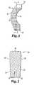
- Superior surface 22 and/or inferior surface 24can also define an angle or taper, as shown in Figure 2 .
- a tapered portion 32can be provided at one end of the spacer body 20, for example to provide a leading end for insertion.
- Loadbearing body 20can also include an instrument hole 34 as best shown in Figure 2 .
- the instrument hole 34can be configured to receive and engage a portion of medical instrument, such as an insertion instrument, to assist a medical practitioner in inserting the loadbearing body 20 between adjacent vertebrae.
- the instrument hole 34can be various shapes such as, circular, rectangular, or triangular, to name a few, and can include attachment adaptations such as threads if desired.
- loadbearing body 20 or a pair of loadbearing bodies 20can be inserted into the interbody space between a pair of vertebrae such that superior surface 22 substantially contacts a surface of the upper vertebrae and inferior surface 24 substantially contacts a surface of the lower vertebrae.
- Surface features 28frictionally engage the surface of the upper vertebrae and surface features 30 frictionally engage the surface of the lower vertebrae.
- one or more loadbearing bodies 20are inserted in the interbody space between a pair of vertebrae in the lumbar region of the recipient's spine. Once implanted, new bone ingrowth can occur into the loadbearing body 20 thereby providing stabilization.
- osteogenic materialssuch as bone (e.g. autologous patient bone), or formulations including osteogenic proteins such as bone morphogenic proteins (BMPs), including for example BMP-2 or BMP-7, can be introduced into the interbody space along with the body or bodies 20, to facilitate fusion of the adjacent vertebra.
- BMPsbone morphogenic proteins
- the biocompatible loadbearing body 40is formed from a collagen-mineral composite as described herein.
- the loadbearing body 40can be sized for placement between a first and a second vertebrae.
- the loadbearing body 40includes a superior surface 42 and an inferior surface 44 separated by planar sidewalls 46 and arcuate sidewall 47.
- Superior surface 42 and inferior surface 44can be planar, arcuate, or combinations of these for contacting the surfaces of the first and second vertebrae, respectively.
- superior surface 42 and inferior surface 44are substantially planar.
- the superior surface 42includes surface features 48.
- the inferior surface 44includes surface features 50.
- the surface features 48 and surface features 50are substantially similar and serrated in shape. As should be appreciated, the serrated shape of surface features 48 and surface features 50 can maintain the loadbearing body 40 between the pair of adjacent vertebrae and resist movement of the loadbearing body 40 from between the recipient's vertebrae.
- surface features 48can be shaped independently of surface features 50. As well, surface features 48 and surface features 50 can extend fully or partially across superior surface 42 and/or inferior surface 44, respectively.
- the loadbearing body 40also includes an opening 52. As illustrated, the opening 52 is substantially rectangular in shape and the opening 52 generally matches the outline of the loadbearing body 40 formed by the planar sidewalls 46 and arcuate sidewall 47. The planar sidewalls 46 and the arcuate sidewall 47 as shown in Figure 3 form a quadrilateral shape. The quadrilateral shape can be useful for implanting the loadbearing body 40 between adjacent cervical vertebrae. As shown in Figure 3 , the opening 52 is generally centrally located in the loadbearing body 40. In other forms, the opening 52 can be located anywhere within the loadbearing body 40. Further, in other forms, multiple openings 52 can be located within loadbearing body 40.
- the loadbearing body 40can be placed between adjacent vertebrae such that superior surface 42 can contact a first vertebrae and surface features 48 can frictionally engage a surface of the first vertebrae. Additionally, the inferior surface 44 can contact a second vertebrae such that surface features 50 can frictionally engage a surface of the second vertebrae. Beneficially, once implanted, new bone ingrowth can occur into the loadbearing body 40 thereby providing stabilization.
- an osteogenic substancesuch as patient bone or an osteogenic protein formulation, as discussed above, can be provided within central opening 52, to facilitate fusion of the adjacent vertebral bodies.
- the biocompatible loadbearing body 60is made from a collagen-mineral composite as described herein.
- the loadbearing body 60includes a superior surface 62 separated from an inferior surface 64 by planar sidewalls 66 and arcuate sidewall 67.
- superior surface 62can be generally planar for contacting a surface of the first vertebrae.
- the inferior surface 64can be generally planar for contacting a surface of the second vertebrae.
- the superior surface 62 and/or inferior surface 64may be arcuate, or a combination of planar and arcuate, for contacting the surface of the first and/or second vertebrae, respectively. Further, the superior surface 62 can be formed independently of the inferior surface 64. Superior surface 62 includes surface features 68 to frictionally engage the first vertebrae. As shown, the surface features 68 are raised portions shaped as serrations. The inferior surface 64 includes surface features 70 to frictionally engage a second vertebrae adjacent to the first vertebrae. The surface features 70 are also shaped as serrations. Again, surface features 68 can be shaped independently of surface features 70 in alternate inventive embodiments, and features 68 and/or 70 can provide frictionally-engaging shapes other than serrated.
- the loadbearing body 40is substantially rectangular in shape, with one curved sidewall.
- sidewalls 66are generally planar, whereas sidewall 67 is convexly arcuate or curved.
- the curved sidewall 66can, for example, be configured to correspond to the anterior curvature of adjacent vertebra between which the loadbearing body 60 will be implanted.
- loadbearing body 60can inserted in the interbody space between adjacent vertebrae such that superior surface 62 contacts a surface of the upper vertebrae and inferior surface 64 contacts a surface of the lower vertebrae. Moreover, surface features 68 can frictionally engage the surface of the upper vertebrae and surface features 70 can frictionally engage a surface of the lower vertebrae. After implanting the loadbearing body 60, new bone ingrowth can occur into and around the loadbearing body 60 thereby providing stabilization. If desired, osteogenic substances may be implanted along with body 60 to facilitate a fusion of the adjacent vertebral bodies.
- the biocompatible loadbearing body 80is made from a composite material as described herein.
- the biocompatible loadbearing body 80includes an outer substantially cylindrical surface 82 and a pair of endwalls 86.
- the outer surface 82is arcuate for contacting a prepared (e.g. drilled) surface of a first vertebrae and a prepared surface of a second vertebrae.
- the surface 82includes surface features 88 for frictionally engaging both the surface of the first vertebrae and the surface of the second vertebrae.
- the surface features 88 as shown in Figure 6are generally threaded or corrugated in shape.
- the threaded shape of surface features 88enables the loadbearing body 80 to be advanced as it is rotated.
- One endwalls 86can include an indentation or slot 90.
- the indentation 90can be sized and shaped for engaging a device for inserting the loadbearing body 80 between adjacent vertebrae.
- Loadbearing body 80further includes a first opening 92 extending between the pair of endwalls 86. As shown, opening 92 is centrally located; however in other embodiments the first opening 92 can be positioned off-center.
- the opening 92can be sized to receive a portion of an inserter instrument.
- the opening 92is shown as circular but it will be understood that it may be shaped differently in other forms of the invention.
- the loadbearing body 80can include a second opening 94 extending through the loadbearing body 80 as shown in Figure 6 .
- Second opening 94can be located within the center of the loadbearing body 80 as shown or second opening 94 can be located off-center of the loadbearing body 80 in another embodiment.
- Second opening 94can be sized to receive autologous patient bone or another osteogenic substance or formulation as discussed above, to facilitate bone growth through opening 94 to participate in the fusion mass.
- loadbearing body 80can be inserted between a pair of vertebrae such that outer surface 82 contacts a surface of the upper vertebrae and a surface of the lower vertebrae.
- Surface features 88can frictionally engage the surface of the upper vertebrae and/or the surface of the lower vertebrae such that once the loadbearing body 80 is implanted, new bone ingrowth can occur into and through the loadbearing body 80.
- the composite materials describedcan be used in a variety of bone implant applications, including the preferred spinal implants and others such as in the repair of cranial defects, iliac crest back-filling, and in the repair of tibial plateau and long bone defects.
- Such implantscan be used to treat major or minor defects in these or other bones caused by trauma, disease, or cogenital defects, for example.
- the implantscan be inserted into a recipient's body during open surgery or during a minimally invasive surgery. Examples of minimally invasive surgery can include laproscopic techniques.
- the present inventionmay form part of a spinal implant kit, wherein the kit includes a spinal implant of the composite material as described herein, along with at least one additional medical device or material, such as an insertion tool, distractor, syringe, vial, needle, or other component.
- the components of the kitsare generally packaged in a sterile condition. Such kits can likewise include instructions for use of the kit components.
Landscapes
- Health & Medical Sciences (AREA)
- Engineering & Computer Science (AREA)
- Chemical & Material Sciences (AREA)
- Biomedical Technology (AREA)
- Orthopedic Medicine & Surgery (AREA)
- General Health & Medical Sciences (AREA)
- Neurology (AREA)
- Veterinary Medicine (AREA)
- Oral & Maxillofacial Surgery (AREA)
- Transplantation (AREA)
- Public Health (AREA)
- Life Sciences & Earth Sciences (AREA)
- Animal Behavior & Ethology (AREA)
- Materials Engineering (AREA)
- Epidemiology (AREA)
- Medicinal Chemistry (AREA)
- Composite Materials (AREA)
- Dermatology (AREA)
- Inorganic Chemistry (AREA)
- Cardiology (AREA)
- Heart & Thoracic Surgery (AREA)
- Vascular Medicine (AREA)
- Prostheses (AREA)
- Materials For Medical Uses (AREA)
Description
- The present invention relates generally to spinal implants for loadbearing applications. The present invention relates to synthetic spinal implants configured for placement between two adjacent vertebrae to facilitate fusion.
- As further background, intervertebral discs, located between the endplates of adjacent vertebrae, stabilize the spine, distribute forces between vertebrae, and cushion vertebral bodies. A normal intervertebral disc includes a semi-gelatinous component, the nucleus pulposus, which is surrounded and confined by an outer, fibrous ring called the annulus fibrosus. In a healthy, undamaged spine, the annulus fibrosus prevents the nucleus pulposus from protruding outside the disc space.
- Spinal discs may be displaced or damaged due to trauma, disease or aging. Disruption of the annulus fibrosus allows the nucleus pulposus to protrude into the vertebral canal, a condition commonly referred to as a herniated or ruptured disc. The extruded nucleus pulposus may press on a spinal nerve, which may result in nerve damage, pain, numbness, muscle weakness and paralysis. Intervertebral discs may also deteriorate due to the normal aging process or disease. As a disc dehydrates and hardens, the disc space height will be reduced leading to instability of the spine, decreased mobility and pain.
- In certain instances, the only relief from the symptoms of these conditions is a discectomy, or surgical removal of a portion or all of an intervertebral disc, followed by fusion (arthrodesis) of the adjacent vertebrae. The removal of the damaged or unhealthy disc will allow the disc space to collapse. Collapse of the disc space can cause instability of the spine, abnormal joint mechanics, premature development of arthritis or nerve damage, in addition to severe pain. Pain relief via discectomy and arthrodesis requires preservation of the disc space and eventual fusion of the affected motion segments.
- Historically, bone grafts have been used to fill the intervertebral space to promote fusion of the adjacent vertebrae across the disc space. In early techniques, bone material was simply disposed between the adjacent vertebrae, typically at the posterior aspect of the vertebra, and the spinal column was stabilized by way of a plate or rod spanning the affected vertebrae. Once fusion occurred, the hardware used to maintain the stability of the segment became superfluous and was a permanent foreign body. Moreover, the surgical procedures necessary to implant a rod or plate to stabilize the level during fusion were frequently lengthy and involved.
- A variety of attempts have been made to develop implants for use in maintaining the disc space until complete arthrodesis is achieved. The implant must provide temporary support and allow bone ingrowth. Success of the discectomy and fusion procedure requires the development of a contiguous growth of bone to create a solid mass because the implant may not withstand the compressive loads on the spine for the life of the patient.
- As examples, several metal spacers have been developed to fill the void between adjacent vertebral bodies and to promote fusion. These include hollow spinal cages that can be filled with osteogenic material, such as autograft, allograft, or osteogenic protein formulations, prior to insertion into the intervertebral space. Apertures defined in the cage communicate with the hollow interior to provide a path for tissue growth between the vertebral endplates.
- Interbody spinal implants fabricated from bone have also been employed. These include for instance threaded bone dowel products and impacted spacers. Bone provides many advantages for use in fusions. It can be incorporated after fusion occurs and therefore will not be a permanent implant. Bone also allows excellent postoperative imaging because it does not cause scattering like metallic implants. Stress shielding is avoided because bone grafts have a similar modulus of elasticity as the surrounding bone.
- Although an all-bone spacer provides these and other benefits, the use of bone presents several challenges. Any spacer which will be placed within the intervertebral disc space must withstand the cyclic loads of the spine. Cortical bone products may have sufficient compressive strength for such use; however, cortical bone will not promote rapid fusion. Cancellous bone is more conducive to fusion but is not biomechanically sound as an intervertebral spacer. As well, suitable allograft bone can be relatively scarce at times, potentially interrupting product supply.
WO 96/40014 WO 96/40014 WO 96/40014 WO 03/071991 WO 03/071991 WO 03/071991 - In view of the background in this area, needs remain for improved and alternative intervertebral spacer implants that are fabricated from readily available materials and which have the mechanical and biological attributes necessary for loadbearing spinal applications. The present invention, in certain embodiments, is addressed to these needs.
- In one embodiment, the present invention provides an intervertebral spinal implant that comprises a biocompatible load bearing composite including reconstituted fibrillar collagen and a particulate mineral, the collagen and the mineral constituting at least 70 w% of said composite in a mineral: collagen weight ratio of at least 15:1. The composite has a wet compressive strength of at least 200 Newtons per square centimeter (N/cm2) and provides a body sized and configured for implant between first and second adjacent vertebrae. The body has superior and inferior surfaces configured to frictionally engage the respective adjacent vertebrae. As examples, the body can be provided in the form of a wedge, dowel or D shape, and can incorporate one or more through holes in which an osteogenic substance can be deposited and retained, either at the point of manufacture or during surgery.
- Advantageous frictional surfaces on the superior and inferior faces of the body can include any of a wide variety of proturbance patterns, including for example teeth, serrations or grooves.
- A method for making such an intervertebral spinal implant may include molding a composition comprising reconstituted fibrillar collagen and mineral particles to provide a loadbearing composite material, desirably having a wet compressive strength of at least about 200 N/cm2. The composite material is shaped to provide a body for introduction between adjacent first and second vertebra; and, surface protuberances are formed on said body configured to frictionally engage the first and second vertebra. In advantageous embodiments, the body is shaped and/or the proturbances are formed during the molding procedure. As well, through holes and/or tool-engaging apertures or other adaptations can be provided in the body during molding or otherwise. The molding can be conducted under compression to provide enhanced strength and density to the inventive composite material and resulting spacers.
- A bone implant material for the implant may comprise a biocompatible composite including reconstituted fibrillar collagen and particulate mineral, wherein the composite has a wet compressive strength of at least about 200 N/cm2, and advantageously also a bulk density of at least about 1 g/cm3. In certain forms, the collagen of the composite can be crosslinked to enhance the strength of the composite material before, during and/or after a molding process used to form the composite. In other forms, the composite can be provided in the form of a molded article configured for receipt at a targeted implant site in contact with patient bone, for example at an interbody or other location within the spine. The composite can be free of bone-derived material, and in certain embodiments is free of collagenous sources other than the reconstituted fibrillar collagen. In still other embodiments, the composite can comprise both fibrillar and soluble collagen, and/or the particulate mineral can comprise a calcium phosphate mineral such as tricalcium phosphate and/or hydroxyapatite.
- Additional embodiments as well as features and advantages of the invention will be apparent from the descriptions herein.
Figure 1 is a top view of a spinal implant of the invention.Figure 2 is a cross-sectional view of the spinal implant shown inFigure 1 taken along line 2-2 and viewed in the direction of the arrows.Figure 3 is a top view of another spinal implant of the invention.Figure 4 is a right side view of the spinal implant shown inFigure 3 .Figure 5 is a perspective view of yet another spinal implant of the invention.Figure 6 is a perspective view of another spinal implant of the invention.- For the purposes of promoting an understanding of the principles of the invention, reference will now be made to certain embodiments thereof and specific language will be used to describe the same.
- As disclosed above, the present invention provides intervertebral spinal implants that include a body formed with a loadbearing, biocompatible high-strength composite material comprising a particulate mineral material and collagen, wherein the loadbearing body is sized and configured for placement between first and second adjacent vertebrae, and in particular in the interbody space between the adjacent vertebrae. The implant body of the invention has an upper surface and a lower surface wherein each of these surfaces are configured to frictionally engage one of the pair of vertebrae.
- Implants of the invention include a synthetic composite material containing a particulate mineral material and collagen. In advantageous inventive embodiments, the particulate mineral material can be a calcium phosphate ceramic. Such materials can, for example, include hydroxyapatite, tricalcium phosphate, or biphasic calcium phosphate. Other calcium-containing mineral materials may also be used, including for example calcium sulfate and bioactive glasses such as Bioglass™. These mineral components may be purchased commercially or obtained or synthesized by methods known in the art. The particulate mineral material may have any suitable particle size, including for example average particle diameters ranging from about 0.05 mm (50 microns) to about 5 millimeters (mm). In certain embodiments, the particulate mineral will have an average particle diameter of about 0.1 mm to about 3 mm.
- As noted above, biphasic calcium phosphate can be used to provide the particulate mineral material in the invention. Desirably, such biphasic calcium phosphate will have a tricalcium phosphate: hydroxyapatite weight ratio of 50:50 to 95:5, more preferably about 70:30 to about 95:5, even more preferably 80:20 to 90:10, and most preferably 85:15. A preferred particulate biphasic calcium phosphate material is known as Mastergraft™, commercially available from Medtronic Sofamor Danek, Inc. The particles in this material include curved surface features beneficial for the conduction of bone growth. Additional information regarding suitable particulate minerals and their preparation is found in
WO 2004/054633 published July 1, 2004 entitled Bone Substitute Material (SDGI Holdings, Inc.). - A wide variety of collagen materials are suitable for combination with the particulate mineral material to form the synthetic composite material in accordance with the present invention. Naturally occurring collagens may be subclassified into several different types depending on their amino acid sequence, carbohydrate content and presence or absence of disulfide cross-links. Types I and III collagen are two of the most common sub-types of collagens. Type I collagen is present in skin, tendon and bone whereas Type III collagen is found primarily in skin. The collagen in the synthetic composite material may be obtained from skin, bone, tendon, or cartilage and purified by methods known in the art. Alternately, the collagen may be purchased commercially.
- The collagen can further be atelopeptide collagen and/or telopeptide collagen. Moreover, non-fibrillar (e.g., soluble) and/or fibrillar collagen may be used. In certain embodiments of the invention, at least some fibrillar collagen is used, and in others embodiments all fibrillar collagen is used. In this regard, fibrillar collagen is collagen that has been reconstituted into its native fibrillar form. In certain preferred aspects, reconstituted fibrillar collagen having fibrils with an average length of 0.1 mm to 20 mm is used, more typically in the range of 0.5 mm to 10 mm.
- The weight ratio of mineral to collagen in composites of the invention will be at least 15:1.
- Other substances can also be incorporated into the composite materials for use in the invention, including for example therapeutic agents such as osteogenic proteins, including BMP-2, BMP-7 and/or other bone morphogenic proteins, demineralized bone, growth factors, antibiotics, etc. In certain embodiments, the bone implant materials are intended to provide a substitute or materials sourced from bone, and can thus be free of any bone-derived materials such as cortical or cancellous bone or demineralized bone. As well, the composites can be predominantly constituted by weight of the collagen and mineral used in their preparation, for example constituted at least 70% of the collagen and mineral, or in other embodiments at least 90% of the collagen and mineral. In specific embodiments, the composite material consists, or consists essentially, of the collagen and mineral materials used in its preparation.
- Composite materials for use in the invention can also incorporate reinforcing elements, including reinforcing filaments such as strands, threads or fibers. Such reinforcing filaments or other elements can in certain enibodiments be made from resorbable materials, including for example resorbable synthetic polymers or collagen. The filaments can be prepared by any suitable means including for instance extrusion, and in variants of the present invention can be relatively longer and/or greater in diameter than the fibrils of the fibrillar collagen employed, typically having a filament length in the range of about 0.5 mm to about 50 mm. These reinforcing materials can be incorporated in a mixture with the reconstituted fibrillar collagen and mineral, which is processed to provide a load bearing body as described herein.
- One form of manufacturing the spinal implant involves casting the synthetic composite material in a mold. The synthetic composite material can take on the shape of the mold such as, crescent, quadrilateral, rectangular, cylindrical, or any other shape. Additionally, the surface of the mold may be smooth or may include raised features or indentations to impart features to the spinal implant. Features from the mold can be imparted to the spinal implant as the synthetic composite material in the mold is dried or otherwise hardened. In particular aspects, a roughened or friction engaging surface can be formed on the superior surface and/or the inferior surface of the loadbearing body. More preferably, protuberances or raised portions can be imparted on the superior surface and/or the inferior surface from the mold. Such examples of protuberances or raised portions are ridges, serrations, pyramids, and teeth, to name a few.
- Further, the mold can impart one or more openings extending through the loadbearing body. This opening in the loadbearing body can be sized to receive portions of a recipient's bone or a medical material such as an osteogenic formulation within the opening. Single or multiple openings can be formed in the loadbearing body. Additionally, the openings can be located anywhere within the spinal implant, for example the opening can be located in the center of the spinal implant or the opening can be a distance from the center of the spinal implant.
- In another manufacturing operation, the synthetic composite material can be partially or completely machined to form a shape for the implant. Examples of such machines are lathes, drills, or other mechanical devices that can be used to shape material. The synthetic composite material can be shaped to form a crescent, a quadrilateral, a rectangle, a cylinder or any other shape that is appropriate to the intended end use. Additionally, the machines can form the roughened surface on the superior surface and/or the inferior surface of the spinal implant, tool engaging features, through-holes for osteogenic or other medical substances, etc.
- In the preparation of implants of the invention, a mixture of the collagen and mineral is typically combined with a liquid to wet the material. Any suitable liquid can be used including, for example, aqueous preparations such as water, aqueous solutions such as saline (e.g. physiological saline), sugar solutions, protic organic solvents, and liquid polyhydroxy compounds such as glycerol and glycerol esters, and mixtures thereof. The liquid may, for example, constitute about 5 to about 70 weight percent of the mixed composition prior to the molding operation. Certain liquids such as water can be removed in part or essentially completely from the formed implant device using conventional drying techniques such as air drying, heated drying, lyophilization, and the like, and will be preferred.
- In one mode of manufacture, a collagen-mineral mixture can be combined with a liquid, desirably with an aqueous preparation, to form a paste. Excess liquid can be removed from the paste by any suitable means, including for example by applying the paste to a liquid-permeable mold or form and draining away excess liquid.
- In certain inventive embodiments, after production of the collagen-mineral composition, the composition is compressed in the production of an enhanced load bearing implant material. For example, a compressive force of at least about 6.89 MPa (1000 psi) can be applied produce composite implant materials of the invention. Typically, compressive forces of from about 6.89 MPa to about 413.69 MPa (1000 to about 60000 psi) will be employed, more typically from about 13.79 to about 137.9 MPa (2000 to about 20000 psi). The duration of compression can be for any suitable period of time to form the loadbearing implant material, typically ranging from several minutes to several days, more typically about 2 to 24 hours.
- Before, during or after molding, including in some instances the application of compressive force to the collagen-mineral containing composition, the composition can be subjected to one or more additional operations such as heating, lyophilizing and/or crosslinking.
- In this regard, crosslinking can be introduced so as to improve the strength of the formed implant. Crosslinking can be achieved by any of a variety of known methods, or combinations thereof. Such methods include for example chemical reaction, the application of energy such as radiant energy (e.g. UV light or microwave energy), drying and/or heating and dye-mediated photo-oxidation; dehydrothermal treatment; enzymatic treatment; and others.
- Chemical crosslinking agents will generally be preferred, including those that contain bifunctional or multifunctional reactive groups, and which react with collagen. Chemical crosslinking can be introduced by exposing the collagen-mineral composition to a chemical crosslinking agent, either by contacting with a solution of the chemical crosslinking agent or by exposure to the vapors of the chemical crosslinking agent. As noted above, this contacting or exposure can occur before, during or after a molding operation. In any event, the resulting material can then be washed to remove substantially all remaining amounts of the chemical crosslinker if needed or desired for the performance or acceptability of the final bone implant.
- Suitable chemical crosslinking agents include mono- and dialdehydes, including glutaraldehyde and formaldehyde; polyepoxy compounds such as glycerol polyglycidyl ethers, polyethylene glycol diglycidyl ethers and other polyepoxy and diepoxy glycidyl ethers; tanning agents including polyvalent metallic oxides such as titanium dioxide, chromium dioxide, aluminum dioxide, zirconium salt, as well as organic tannins and other phenolic oxides derived from plants; chemicals for esterification or carboxyl groups followed by reaction with hydrazide to form activated acyl azide functionalities in the collagen; dicyclohexyl carbodiimide and its derivatives as well as other heterobifunctional crosslinking agents; hexamethylene diisocyante; sugars, including glucose, will also crosslink collagen.
- In certain aspects of the invention, the prepared composite implant materials of the invention will be relatively dense, hard materials, for example possessing a bulk density (the weight of the implant divided by its volume) of at least 1 g/cm3, more typically about 1 g/cm3 to about 2 g/cm3.
- Additionally or alternatively, prepared composite implant materials of the invention can also possess enhanced loadbearing properties, for example exhibiting a wet compressive strength of at least 200 N/cm2, typically in the range of about 200 N/cm2 to about 10000 N/cm2, typically in the range of about 200 N/cm2 to about 5000 N/cm2, and in certain embodiments in the range of 200 N/cm2 to 2000 N/cm2. Such wet compressive strengths can be measured with the implant saturated with physiological saline, for example after being immersed in physiological saline for 12-24 hours.
- The composite materials of the invention can be lyophilized after molding or other formation is completed, for example using conventionnal conditions such as a temperature of from about -20° to about -55° C, a vacuum of from about 20 to about 13.33 Pa (150 to about 100 m Torr), for a suitable period of time, e.g. ranging from about 4 to about 48 hours.
- The resulting implant can assume a determined or regular form or configuration completely or partially as a result of the molding operation..General overall forms include, for example, blocks, disks, pins, wedges, cylinders, threaded cylinders, and the like.
- In certain modes of practicing the invention, the loadbearing composite of the invention can be used in the formation of a spinal implant, and in particular embodiments an interbody spinal fusion implant. For such purposes, the collagen-mineral composite can provide an implant body sized for receipt at a location between first and second adjacent vertebrae of a mammal, including a human, and can be configured to facilitate fusion of the two vertebrae. Spinal implants of advantageous embodiments of the invention include a loadbearing body having a superior or upper surface and an inferior or lower surface separated by at least one sidewall. In particular, the upper and lower surfaces can be generally planar, arcuate or combinations of these, or any other suitable configuration for contacting a surface of a first vertebrae, such as a vertebral endplate. Further, at least one of and desirably both of the upper and lower surfaces are configured to frictionally engage the first and second vertebral surfaces. The frictional engagement between the upper surface and the first vertebrae assists the loadbearing body in resisting movement after it is implanted. In one form, the upper and/or lower surface can have a generally non-smooth surface configuration to engage the surface of an adjacent vertebrae. For example, the upper and/or lower surface can be roughened, e.g., by having protuberances, raised portions, and/or grooves to frictionally engage the first vertebrae.
- The protuberances or raised portions could be such shapes as serrations, teeth (including directional and non-directional teeth), ridges, grooves, or pyramids, to name a few.
- The sidewall of the loadbearing body in implants of the invention can be arcuate, planar or combinations of these. In certain inventive embodiments, at least one curved sidewall portion will be provided in a spinal spacer, wherein the curved sidewall portion is configured to substantially correspond to the curvature of an adjacent vertebral body.
- With reference now to
Figures 1 and 2 , an illustrative spinal implant of the invention will now be described. The biocompatibleloadbearing body 20 is made from a particulate mineral/collagen composite as described herein. Biocompatibleloadbearing body 20 includes asuperior surface 22 and aninferior surface 24 that are separated by sidewalls 26. The loadbearing 20 is shaped substantially like a 'C' shape or a crescent shape in the illustrated device. Theloadbearing body 20 can be sized for placement between two adjacent vertebrae, and in particular for placement within an interbody space between first and second adjacent vertebrae. Thesuperior surface 22 includes surface features 28. Surface features 28 can extend fully acrosssuperior surface 22 or in another form surface features 28 can extend partially acrosssuperior surface 22. In particular, the surface features 28 are a serrated shape, however other embodiments the surface features 28 can provide different frictionally-engaging shapes. Theinferior surface 24 includes surface features 30. As shown, surface features 30 are serrated. As with the superior surface, surface features 30 can extend partially or fully acrossinferior surface 24. In general aspects of the invention, surface features 30 may be substantially similar to surface features 28 or surface features 30 may be a different shape than surface features 28. - As shown in
Figures 1 and 2 , the inferior andsuperior surfaces sidewalls 26 are arcuate, providing an overall "C" shape to thespacer body 20.Superior surface 22 and/orinferior surface 24 can also define an angle or taper, as shown inFigure 2 . As also illustrated, a taperedportion 32 can be provided at one end of thespacer body 20, for example to provide a leading end for insertion.Loadbearing body 20 can also include aninstrument hole 34 as best shown inFigure 2 . Theinstrument hole 34 can be configured to receive and engage a portion of medical instrument, such as an insertion instrument, to assist a medical practitioner in inserting theloadbearing body 20 between adjacent vertebrae. Theinstrument hole 34 can be various shapes such as, circular, rectangular, or triangular, to name a few, and can include attachment adaptations such as threads if desired. - In use,
loadbearing body 20 or a pair ofloadbearing bodies 20 can be inserted into the interbody space between a pair of vertebrae such thatsuperior surface 22 substantially contacts a surface of the upper vertebrae andinferior surface 24 substantially contacts a surface of the lower vertebrae. Surface features 28 frictionally engage the surface of the upper vertebrae and surface features 30 frictionally engage the surface of the lower vertebrae. Preferably, one or moreloadbearing bodies 20 are inserted in the interbody space between a pair of vertebrae in the lumbar region of the recipient's spine. Once implanted, new bone ingrowth can occur into theloadbearing body 20 thereby providing stabilization. As well, osteogenic materials such as bone (e.g. autologous patient bone), or formulations including osteogenic proteins such as bone morphogenic proteins (BMPs), including for example BMP-2 or BMP-7, can be introduced into the interbody space along with the body orbodies 20, to facilitate fusion of the adjacent vertebra. - With reference now to
Figures 3 and 4 , another illustrative biocompatibleloadbearing body 40 of the invention will now be described. The biocompatibleloadbearing body 40 is formed from a collagen-mineral composite as described herein. Theloadbearing body 40 can be sized for placement between a first and a second vertebrae. Theloadbearing body 40 includes asuperior surface 42 and aninferior surface 44 separated byplanar sidewalls 46 andarcuate sidewall 47.Superior surface 42 andinferior surface 44 can be planar, arcuate, or combinations of these for contacting the surfaces of the first and second vertebrae, respectively. As illustrated,superior surface 42 andinferior surface 44 are substantially planar. Thesuperior surface 42 includes surface features 48. Theinferior surface 44 includes surface features 50. As shown inFigure 4 , the surface features 48 and surface features 50 are substantially similar and serrated in shape. As should be appreciated, the serrated shape of surface features 48 and surface features 50 can maintain theloadbearing body 40 between the pair of adjacent vertebrae and resist movement of theloadbearing body 40 from between the recipient's vertebrae. - In other embodiments, surface features 48 can be shaped independently of surface features 50. As well, surface features 48 and surface features 50 can extend fully or partially across
superior surface 42 and/orinferior surface 44, respectively. Theloadbearing body 40 also includes anopening 52. As illustrated, theopening 52 is substantially rectangular in shape and theopening 52 generally matches the outline of theloadbearing body 40 formed by theplanar sidewalls 46 andarcuate sidewall 47. Theplanar sidewalls 46 and thearcuate sidewall 47 as shown inFigure 3 form a quadrilateral shape. The quadrilateral shape can be useful for implanting theloadbearing body 40 between adjacent cervical vertebrae. As shown inFigure 3 , theopening 52 is generally centrally located in theloadbearing body 40. In other forms, theopening 52 can be located anywhere within theloadbearing body 40. Further, in other forms,multiple openings 52 can be located withinloadbearing body 40. - In use, the
loadbearing body 40 can be placed between adjacent vertebrae such thatsuperior surface 42 can contact a first vertebrae and surface features 48 can frictionally engage a surface of the first vertebrae. Additionally, theinferior surface 44 can contact a second vertebrae such that surface features 50 can frictionally engage a surface of the second vertebrae. Beneficially, once implanted, new bone ingrowth can occur into theloadbearing body 40 thereby providing stabilization. As well, an osteogenic substance such as patient bone or an osteogenic protein formulation, as discussed above, can be provided withincentral opening 52, to facilitate fusion of the adjacent vertebral bodies. - With reference to
Figure 5 , another illustrative biocompatibleloadbearing body 60 of the invention will be described. The biocompatibleloadbearing body 60 is made from a collagen-mineral composite as described herein. Theloadbearing body 60 includes asuperior surface 62 separated from aninferior surface 64 byplanar sidewalls 66 andarcuate sidewall 67. As shown,superior surface 62 can be generally planar for contacting a surface of the first vertebrae. Similarly, theinferior surface 64 can be generally planar for contacting a surface of the second vertebrae. As will be appreciated, in other embodiments, thesuperior surface 62 and/orinferior surface 64 may be arcuate, or a combination of planar and arcuate, for contacting the surface of the first and/or second vertebrae, respectively. Further, thesuperior surface 62 can be formed independently of theinferior surface 64.Superior surface 62 includes surface features 68 to frictionally engage the first vertebrae. As shown, the surface features 68 are raised portions shaped as serrations. Theinferior surface 64 includes surface features 70 to frictionally engage a second vertebrae adjacent to the first vertebrae. The surface features 70 are also shaped as serrations. Again, surface features 68 can be shaped independently of surface features 70 in alternate inventive embodiments, and features 68 and/or 70 can provide frictionally-engaging shapes other than serrated. As shown, theloadbearing body 40 is substantially rectangular in shape, with one curved sidewall. In particular, sidewalls 66 are generally planar, whereassidewall 67 is convexly arcuate or curved. Thecurved sidewall 66 can, for example, be configured to correspond to the anterior curvature of adjacent vertebra between which theloadbearing body 60 will be implanted. - In use,
loadbearing body 60 can inserted in the interbody space between adjacent vertebrae such thatsuperior surface 62 contacts a surface of the upper vertebrae andinferior surface 64 contacts a surface of the lower vertebrae. Moreover, surface features 68 can frictionally engage the surface of the upper vertebrae and surface features 70 can frictionally engage a surface of the lower vertebrae. After implanting theloadbearing body 60, new bone ingrowth can occur into and around theloadbearing body 60 thereby providing stabilization. If desired, osteogenic substances may be implanted along withbody 60 to facilitate a fusion of the adjacent vertebral bodies. - Referring to
Figure 6 , shown is another biocompatibleloadbearing body 80 according to the present invention. The biocompatibleloadbearing body 80 is made from a composite material as described herein. The biocompatibleloadbearing body 80 includes an outer substantiallycylindrical surface 82 and a pair ofendwalls 86. Theouter surface 82 is arcuate for contacting a prepared (e.g. drilled) surface of a first vertebrae and a prepared surface of a second vertebrae. Further, thesurface 82 includes surface features 88 for frictionally engaging both the surface of the first vertebrae and the surface of the second vertebrae. The surface features 88 as shown inFigure 6 are generally threaded or corrugated in shape. In certain embodiments, the threaded shape of surface features 88 enables theloadbearing body 80 to be advanced as it is rotated. Oneendwalls 86 can include an indentation or slot 90. The indentation 90 can be sized and shaped for engaging a device for inserting theloadbearing body 80 between adjacent vertebrae.Loadbearing body 80 further includes afirst opening 92 extending between the pair ofendwalls 86. As shown, opening 92 is centrally located; however in other embodiments thefirst opening 92 can be positioned off-center. Theopening 92 can be sized to receive a portion of an inserter instrument. Theopening 92 is shown as circular but it will be understood that it may be shaped differently in other forms of the invention. Theloadbearing body 80 can include asecond opening 94 extending through theloadbearing body 80 as shown inFigure 6 .Second opening 94 can be located within the center of theloadbearing body 80 as shown orsecond opening 94 can be located off-center of theloadbearing body 80 in another embodiment.Second opening 94 can be sized to receive autologous patient bone or another osteogenic substance or formulation as discussed above, to facilitate bone growth through opening 94 to participate in the fusion mass. - In use,
loadbearing body 80 can be inserted between a pair of vertebrae such thatouter surface 82 contacts a surface of the upper vertebrae and a surface of the lower vertebrae. Surface features 88 can frictionally engage the surface of the upper vertebrae and/or the surface of the lower vertebrae such that once theloadbearing body 80 is implanted, new bone ingrowth can occur into and through theloadbearing body 80. - Generally speaking, the composite materials described can be used in a variety of bone implant applications, including the preferred spinal implants and others such as in the repair of cranial defects, iliac crest back-filling, and in the repair of tibial plateau and long bone defects. Such implants can be used to treat major or minor defects in these or other bones caused by trauma, disease, or cogenital defects, for example. The implants can be inserted into a recipient's body during open surgery or during a minimally invasive surgery. Examples of minimally invasive surgery can include laproscopic techniques.
- The present invention may form part of a spinal implant kit, wherein the kit includes a spinal implant of the composite material as described herein, along with at least one additional medical device or material, such as an insertion tool, distractor, syringe, vial, needle, or other component. The components of the kits are generally packaged in a sterile condition. Such kits can likewise include instructions for use of the kit components.
Claims (13)
- An intervertebral spinal implant, consisting of:a biocompatible load bearing composite including reconstituted fibrillar collagen and particulate mineral, the collagen and the mineral constituting at least 70% by weight of said composite, in a mineral : collagen weight ratio of at least 15: 1, said composite having a wet compressive strength of at least 200 N/cm2 and a bulk density of at least 1 g/cm3, the wet compressive strength being measured with the implant saturated with physiological saline, and providing a body sized and configured for implant between adjacent vertebrae, said body having a superior surface configured to frictionally engage one of said vertebrae, and an inferior surface configured to frictionally engage the another of said vertebrae, wherein said superior and inferior surfaces comprise protuberances formed in said composite for frictionally engaging the adjacent vertebrae.
- The spinal implant of claim 1, wherein:said particulate mineral comprises a synthetic ceramic;wherein, optionally, said synthetic ceramic comprises tricalcium phosphate;wherein, further optionally, said synthetic ceramic comprises biphasic calcium phosphate.
- The spinal implant of claim 2, wherein:said biphasic calcium phosphate has a weight ratio of tricalcium phosphate to hydroxyapatite of 50:50 to 95:5;wherein, optionally, said ratio of tricalcium phosphate to hydroxyapatite is 80:20 to 90:10;wherein, further optionally, said ratio of tricalcium phosphate to hydroxyapatite is 85:15.
- The spinal implant of claim 1, wherein:said protuberances selected from the group consisting of serrations, teeth, ridges, grooves and pyramids;wherein said protuberances, optionally, comprise teeth, serrations and/or grooves.
- The spinal implant of claim 1, wherein:said composite exhibits a wet compressive strength of 200 N/cm2 to 2000 N/cm2.
- The spinal implant of claim 1, wherein:said composite also includes reinforcing filaments; wherein, optionally, said reinforcing filaments comprise collagen threads.
- The spinal implant of claim 1, wherein:said body includes at least one opening therethrough configured to receive an osteogenic material.
- The spinal implant of claim 1, wherein:said body includes at least one aperture configured for attachment to a medical delivery instrument.
- The spinal implant of claim 1, wherein:said reconstituted fibrillar collagen has filaments with an average length of 0.1 mm to 20 mm;wherein, optionally, said reconstituted fibrillar collagen has filaments with an average length of 0.5 mm to 10 mm.
- The spinal implant of claim 1, further comprising non-fibrillar collagen.
- The spinal implant of claim 1, wherein:the collagen and mineral constitute at least 90% by weight of said composite;wherein, optionally, said composite consists, or consists essentially, of the collagen and mineral.
- The spinal implant of claim 1, wherein:said implant is free of bone-derived materials.
- The spinal implant of claim 1, wherein:said implant is free of cortical bone, cancellous bone and demineralized bone.
Priority Applications (1)
| Application Number | Priority Date | Filing Date | Title |
|---|---|---|---|
| EP10013694AEP2272470A3 (en) | 2005-04-29 | 2006-04-19 | Synthetic loadbearing collagen-mineral composites for spinal implants |
Applications Claiming Priority (2)
| Application Number | Priority Date | Filing Date | Title |
|---|---|---|---|
| US11/118,082US7857853B2 (en) | 2005-04-29 | 2005-04-29 | Synthetic loadbearing collagen-mineral composites useful for spinal implants, and methods of manufacture |
| PCT/US2006/014812WO2006118803A2 (en) | 2005-04-29 | 2006-04-19 | Synthetic loadbearing collagen-mineral composites for spinal implants |
Related Child Applications (1)
| Application Number | Title | Priority Date | Filing Date |
|---|---|---|---|
| EP10013694ADivision-IntoEP2272470A3 (en) | 2005-04-29 | 2006-04-19 | Synthetic loadbearing collagen-mineral composites for spinal implants |
Publications (2)
| Publication Number | Publication Date |
|---|---|
| EP1883377A2 EP1883377A2 (en) | 2008-02-06 |
| EP1883377B1true EP1883377B1 (en) | 2014-03-12 |
Family
ID=37106248
Family Applications (2)
| Application Number | Title | Priority Date | Filing Date |
|---|---|---|---|
| EP06750769.9ANot-in-forceEP1883377B1 (en) | 2005-04-29 | 2006-04-19 | Synthetic loadbearing collagen-mineral composites for spinal implants |
| EP10013694AWithdrawnEP2272470A3 (en) | 2005-04-29 | 2006-04-19 | Synthetic loadbearing collagen-mineral composites for spinal implants |
Family Applications After (1)
| Application Number | Title | Priority Date | Filing Date |
|---|---|---|---|
| EP10013694AWithdrawnEP2272470A3 (en) | 2005-04-29 | 2006-04-19 | Synthetic loadbearing collagen-mineral composites for spinal implants |
Country Status (7)
| Country | Link |
|---|---|
| US (2) | US7857853B2 (en) |
| EP (2) | EP1883377B1 (en) |
| JP (1) | JP4851513B2 (en) |
| CN (1) | CN101166486B (en) |
| AU (1) | AU2006242649B2 (en) |
| ES (1) | ES2456949T3 (en) |
| WO (1) | WO2006118803A2 (en) |
Families Citing this family (44)
| Publication number | Priority date | Publication date | Assignee | Title |
|---|---|---|---|---|
| WO2006058221A2 (en) | 2004-11-24 | 2006-06-01 | Abdou Samy M | Devices and methods for inter-vertebral orthopedic device placement |
| US20070077267A1 (en)* | 2005-10-03 | 2007-04-05 | Sdgi Holdings, Inc. | Bioactive composite implants |
| US8524265B2 (en)* | 2006-08-17 | 2013-09-03 | Warsaw Orthopedic, Inc. | Medical implant sheets useful for tissue regeneration |
| US20080112874A1 (en)* | 2006-08-31 | 2008-05-15 | Burkes Douglas E | Method for producing calcium phosphate powders using an auto-ignition combustion synthesis reaction |
| USD585553S1 (en) | 2007-02-22 | 2009-01-27 | Zimmer Spine, Inc. | Spinal implant |
| USD580551S1 (en) | 2007-02-01 | 2008-11-11 | Zimmer Spine, Inc. | Spinal implant |
| USD566842S1 (en) | 2007-02-19 | 2008-04-15 | Zimmer Spine, Inc. | Spinal implant |
| USD595853S1 (en)* | 2007-02-27 | 2009-07-07 | Zimmer Spine, Inc. | Spinal implant |
| USD611147S1 (en) | 2007-02-27 | 2010-03-02 | Zimmer Spine, Inc. | Spinal implant |
| US8470040B2 (en)* | 2008-04-02 | 2013-06-25 | Pioneer Surgical Technology, Inc. | Intervertebral implant devices for supporting vertebrae and devices and methods for insertion thereof |
| US9492375B2 (en)* | 2008-07-23 | 2016-11-15 | Warsaw Orthopedic, Inc. | Foam carrier for bone grafting |
| US20100226959A1 (en)* | 2009-03-04 | 2010-09-09 | Warsaw Orthopedic, Inc. | Matrix that prolongs growth factor release |
| US20110054533A1 (en)* | 2009-08-26 | 2011-03-03 | Binder Lawrence J | Spinous fusion device |
| US20120273993A1 (en) | 2009-11-24 | 2012-11-01 | Collplant Ltd. | Method of generating collagen fibers |
| US8764806B2 (en) | 2009-12-07 | 2014-07-01 | Samy Abdou | Devices and methods for minimally invasive spinal stabilization and instrumentation |
| US8475824B2 (en) | 2010-01-26 | 2013-07-02 | Warsaw Orthopedic, Inc. | Resorbable matrix having elongated particles |
| US8758791B2 (en) | 2010-01-26 | 2014-06-24 | Warsaw Orthopedic, Inc. | Highly compression resistant matrix with porous skeleton |
| WO2011092262A1 (en)* | 2010-01-28 | 2011-08-04 | Universität Zürich | Method and device for modelling tendinous tissue into a desired shape |
| AU2011223652B2 (en) | 2010-03-03 | 2015-01-29 | Novabone Products, Llc | Devices and methods for the regeneration of bony defects |
| US9144629B2 (en) | 2010-03-03 | 2015-09-29 | Novabone Products, Llc | Ionically crosslinked materials and methods for production |
| US9199032B2 (en) | 2010-03-03 | 2015-12-01 | Novabone Products, Llc | System and kit for delivering collagen bioglass composite bone grafting materials for regenerating hard tissues |
| WO2012066543A2 (en) | 2010-11-16 | 2012-05-24 | Collplant Ltd. | Collagen structures and method of fabricating the same |
| US9717779B2 (en) | 2011-01-31 | 2017-08-01 | Warsaw Orthopedic, Inc. | Implantable matrix having optimum ligand concentrations |
| US8845728B1 (en) | 2011-09-23 | 2014-09-30 | Samy Abdou | Spinal fixation devices and methods of use |
| US20130226240A1 (en) | 2012-02-22 | 2013-08-29 | Samy Abdou | Spinous process fixation devices and methods of use |
| US9585764B2 (en)* | 2012-07-26 | 2017-03-07 | Warsaw Orthopedic, Inc. | Bone implant device |
| US9198767B2 (en) | 2012-08-28 | 2015-12-01 | Samy Abdou | Devices and methods for spinal stabilization and instrumentation |
| CA2886865A1 (en) | 2012-10-05 | 2014-04-10 | Novabone Products, Llc | Novel ionically crosslinked materials and methods for production |
| US9320617B2 (en) | 2012-10-22 | 2016-04-26 | Cogent Spine, LLC | Devices and methods for spinal stabilization and instrumentation |
| TWI517866B (en)* | 2012-11-05 | 2016-01-21 | Far Eastern New Century Corp | Porous bone filling material |
| US9566169B2 (en) | 2014-03-13 | 2017-02-14 | DePuy Synthes Products, Inc. | ACIS allograft designs |
| CN104368044A (en)* | 2014-11-05 | 2015-02-25 | 天津市镁胜生物技术有限公司 | Collagen-based biodegradable spinal fusion cage and preparation method thereof |
| US10238507B2 (en) | 2015-01-12 | 2019-03-26 | Surgentec, Llc | Bone graft delivery system and method for using same |
| US20160213405A1 (en)* | 2015-01-27 | 2016-07-28 | K2M, Inc. | Vertebral plate systems and methods of use |
| US10028841B2 (en) | 2015-01-27 | 2018-07-24 | K2M, Inc. | Interbody spacer |
| US10857003B1 (en) | 2015-10-14 | 2020-12-08 | Samy Abdou | Devices and methods for vertebral stabilization |
| US10709814B2 (en)* | 2016-04-22 | 2020-07-14 | Warsaw Orthopedic, Inc. | Osteoimplant comprising an insoluble fibrous polymer |
| US10973648B1 (en) | 2016-10-25 | 2021-04-13 | Samy Abdou | Devices and methods for vertebral bone realignment |
| US10744000B1 (en) | 2016-10-25 | 2020-08-18 | Samy Abdou | Devices and methods for vertebral bone realignment |
| WO2019051260A1 (en) | 2017-09-08 | 2019-03-14 | Pioneer Surgical Technology, Inc. | Intervertebral implants, instruments, and methods |
| USD907771S1 (en) | 2017-10-09 | 2021-01-12 | Pioneer Surgical Technology, Inc. | Intervertebral implant |
| US10687828B2 (en) | 2018-04-13 | 2020-06-23 | Surgentec, Llc | Bone graft delivery system and method for using same |
| US11116647B2 (en) | 2018-04-13 | 2021-09-14 | Surgentec, Llc | Bone graft delivery system and method for using same |
| US11179248B2 (en) | 2018-10-02 | 2021-11-23 | Samy Abdou | Devices and methods for spinal implantation |
Family Cites Families (23)
| Publication number | Priority date | Publication date | Assignee | Title |
|---|---|---|---|---|
| US4888366A (en)* | 1984-10-24 | 1989-12-19 | Collagen Corporation | Inductive collagen-based bone repair preparations |
| US4865602A (en)* | 1986-11-06 | 1989-09-12 | Collagen Corporation | Gamma irradiation of collagen/mineral mixtures |
| US5782919A (en)* | 1995-03-27 | 1998-07-21 | Sdgi Holdings, Inc. | Interbody fusion device and method for restoration of normal spinal anatomy |
| US5702449A (en)* | 1995-06-07 | 1997-12-30 | Danek Medical, Inc. | Reinforced porous spinal implants |
| US5776193A (en) | 1995-10-16 | 1998-07-07 | Orquest, Inc. | Bone grafting matrix |
| US6423095B1 (en)* | 1995-10-16 | 2002-07-23 | Sdgi Holdings, Inc. | Intervertebral spacers |
| US5718012A (en)* | 1996-05-28 | 1998-02-17 | Organogenesis, Inc. | Method of strength enhancement of collagen constructs |
| WO1998017209A2 (en)* | 1996-10-23 | 1998-04-30 | Sdgi Holdings, Inc. | Spinal spacer |
| US6037519A (en)* | 1997-10-20 | 2000-03-14 | Sdgi Holdings, Inc. | Ceramic fusion implants and compositions |
| WO1999009914A1 (en) | 1997-08-27 | 1999-03-04 | University Of Florida Tissue Bank, Inc. | Cortical bone cervical smith-robinson fusion implant |
| JP4156197B2 (en)* | 1998-08-06 | 2008-09-24 | ウォーソー・オーソペディック・インコーポレーテッド | Composite intervertebral spacer |
| EP1150726B1 (en)* | 1999-02-04 | 2003-11-05 | SDGI Holdings, Inc. | Highly-mineralized osteogenic sponge compositions, and uses thereof |
| US20070233272A1 (en)* | 1999-02-23 | 2007-10-04 | Boyce Todd M | Shaped load-bearing osteoimplant and methods of making same |
| US6294187B1 (en)* | 1999-02-23 | 2001-09-25 | Osteotech, Inc. | Load-bearing osteoimplant, method for its manufacture and method of repairing bone using same |
| US6468311B2 (en)* | 2001-01-22 | 2002-10-22 | Sdgi Holdings, Inc. | Modular interbody fusion implant |
| EP1383549A1 (en)* | 2001-02-14 | 2004-01-28 | Osteotech, Inc. | Implant derived from bone |
| JP2003210499A (en)* | 2002-01-23 | 2003-07-29 | Takiron Co Ltd | Biomaterial for artificial cartilage and its manufacturing method |
| JP4699759B2 (en)* | 2002-11-06 | 2011-06-15 | 独立行政法人物質・材料研究機構 | Apatite / collagen crosslinked porous body containing self-organized apatite / collagen composite and method for producing the same |
| US6761739B2 (en)* | 2002-11-25 | 2004-07-13 | Musculoskeletal Transplant Foundation | Cortical and cancellous allograft spacer |
| DE10258773A1 (en) | 2002-12-16 | 2004-07-08 | SDGI Holding, Inc., Wilmington | Bone substitute material |
| AU2004212942A1 (en)* | 2003-02-14 | 2004-09-02 | Depuy Spine, Inc. | In-situ formed intervertebral fusion device |
| US6974862B2 (en)* | 2003-06-20 | 2005-12-13 | Kensey Nash Corporation | High density fibrous polymers suitable for implant |
| US7723395B2 (en)* | 2004-04-29 | 2010-05-25 | Kensey Nash Corporation | Compressed porous materials suitable for implant |
- 2005
- 2005-04-29USUS11/118,082patent/US7857853B2/ennot_activeExpired - Fee Related
- 2006
- 2006-04-19EPEP06750769.9Apatent/EP1883377B1/ennot_activeNot-in-force
- 2006-04-19ESES06750769.9Tpatent/ES2456949T3/enactiveActive
- 2006-04-19EPEP10013694Apatent/EP2272470A3/ennot_activeWithdrawn
- 2006-04-19CNCN2006800146492Apatent/CN101166486B/ennot_activeExpired - Fee Related
- 2006-04-19JPJP2008508928Apatent/JP4851513B2/ennot_activeExpired - Fee Related
- 2006-04-19AUAU2006242649Apatent/AU2006242649B2/ennot_activeCeased
- 2006-04-19WOPCT/US2006/014812patent/WO2006118803A2/enactiveApplication Filing
- 2010
- 2010-08-31USUS12/872,083patent/US8252055B2/ennot_activeExpired - Fee Related
Also Published As
| Publication number | Publication date |
|---|---|
| CN101166486B (en) | 2010-10-06 |
| EP1883377A2 (en) | 2008-02-06 |
| EP2272470A3 (en) | 2011-01-26 |
| JP4851513B2 (en) | 2012-01-11 |
| AU2006242649A1 (en) | 2006-11-09 |
| CN101166486A (en) | 2008-04-23 |
| AU2006242649B2 (en) | 2011-08-04 |
| WO2006118803A3 (en) | 2007-07-26 |
| US20060247772A1 (en) | 2006-11-02 |
| US7857853B2 (en) | 2010-12-28 |
| ES2456949T3 (en) | 2014-04-24 |
| US20100320647A1 (en) | 2010-12-23 |
| EP2272470A2 (en) | 2011-01-12 |
| US8252055B2 (en) | 2012-08-28 |
| JP2008539001A (en) | 2008-11-13 |
| WO2006118803A2 (en) | 2006-11-09 |
Similar Documents
| Publication | Publication Date | Title |
|---|---|---|
| EP1883377B1 (en) | Synthetic loadbearing collagen-mineral composites for spinal implants | |
| US7323011B2 (en) | Cortical and cancellous allograft cervical fusion block | |
| US6761739B2 (en) | Cortical and cancellous allograft spacer | |
| AU2010257282B2 (en) | Bone graft substitute | |
| US8445554B2 (en) | Compressed porous materials suitable for implant | |
| US20010018614A1 (en) | Implants for orthopedic applications | |
| US20090187245A1 (en) | Interbody fusion hybrid graft | |
| CA2379663A1 (en) | Cartilage or bone matrix as a nucleic acid delivery vehicle | |
| JP4313005B2 (en) | Implant material | |
| CA2379665A1 (en) | Reduced antigenicity tissue (rat) implants | |
| AU2012244219B2 (en) | Bone graft substitute | |
| US20120259425A1 (en) | Precision Shaped Compressed Demineralized Cancellous Bone Product and Method to Make Same | |
| AU2007203182A1 (en) | Cortical and cancellous allograft cervical fusion block implant |
Legal Events
| Date | Code | Title | Description |
|---|---|---|---|
| PUAI | Public reference made under article 153(3) epc to a published international application that has entered the european phase | Free format text:ORIGINAL CODE: 0009012 | |
| 17P | Request for examination filed | Effective date:20071126 | |
| AK | Designated contracting states | Kind code of ref document:A2 Designated state(s):AT BE BG CH CY CZ DE DK EE ES FI FR GB GR HU IE IS IT LI LT LU LV MC NL PL PT RO SE SI SK TR | |
| AX | Request for extension of the european patent | Extension state:AL BA HR MK YU | |
| DAX | Request for extension of the european patent (deleted) | ||
| 17Q | First examination report despatched | Effective date:20081023 | |
| REG | Reference to a national code | Ref country code:DE Ref legal event code:R079 Ref document number:602006040632 Country of ref document:DE Free format text:PREVIOUS MAIN CLASS: A61F0002440000 Ipc:A61F0002280000 | |
| GRAP | Despatch of communication of intention to grant a patent | Free format text:ORIGINAL CODE: EPIDOSNIGR1 | |
| RIC1 | Information provided on ipc code assigned before grant | Ipc:A61L 27/46 20060101ALI20130905BHEP Ipc:A61F 2/28 20060101AFI20130905BHEP Ipc:A61F 2/44 20060101ALI20130905BHEP Ipc:A61F 2/30 20060101ALI20130905BHEP | |
| INTG | Intention to grant announced | Effective date:20130918 | |
| GRAS | Grant fee paid | Free format text:ORIGINAL CODE: EPIDOSNIGR3 | |
| GRAA | (expected) grant | Free format text:ORIGINAL CODE: 0009210 | |
| AK | Designated contracting states | Kind code of ref document:B1 Designated state(s):AT BE BG CH CY CZ DE DK EE ES FI FR GB GR HU IE IS IT LI LT LU LV MC NL PL PT RO SE SI SK TR | |
| REG | Reference to a national code | Ref country code:GB Ref legal event code:FG4D | |
| REG | Reference to a national code | Ref country code:CH Ref legal event code:EP | |
| REG | Reference to a national code | Ref country code:AT Ref legal event code:REF Ref document number:655720 Country of ref document:AT Kind code of ref document:T Effective date:20140315 | |
| REG | Reference to a national code | Ref country code:IE Ref legal event code:FG4D | |
| REG | Reference to a national code | Ref country code:ES Ref legal event code:FG2A Ref document number:2456949 Country of ref document:ES Kind code of ref document:T3 Effective date:20140424 Ref country code:DE Ref legal event code:R096 Ref document number:602006040632 Country of ref document:DE Effective date:20140424 | |
| REG | Reference to a national code | Ref country code:NL Ref legal event code:VDEP Effective date:20140312 | |
| PG25 | Lapsed in a contracting state [announced via postgrant information from national office to epo] | Ref country code:LT Free format text:LAPSE BECAUSE OF FAILURE TO SUBMIT A TRANSLATION OF THE DESCRIPTION OR TO PAY THE FEE WITHIN THE PRESCRIBED TIME-LIMIT Effective date:20140312 | |
| REG | Reference to a national code | Ref country code:AT Ref legal event code:MK05 Ref document number:655720 Country of ref document:AT Kind code of ref document:T Effective date:20140312 | |
| REG | Reference to a national code | Ref country code:LT Ref legal event code:MG4D | |
| PG25 | Lapsed in a contracting state [announced via postgrant information from national office to epo] | Ref country code:SE Free format text:LAPSE BECAUSE OF FAILURE TO SUBMIT A TRANSLATION OF THE DESCRIPTION OR TO PAY THE FEE WITHIN THE PRESCRIBED TIME-LIMIT Effective date:20140312 Ref country code:FI Free format text:LAPSE BECAUSE OF FAILURE TO SUBMIT A TRANSLATION OF THE DESCRIPTION OR TO PAY THE FEE WITHIN THE PRESCRIBED TIME-LIMIT Effective date:20140312 Ref country code:CY Free format text:LAPSE BECAUSE OF FAILURE TO SUBMIT A TRANSLATION OF THE DESCRIPTION OR TO PAY THE FEE WITHIN THE PRESCRIBED TIME-LIMIT Effective date:20140312 | |
| PG25 | Lapsed in a contracting state [announced via postgrant information from national office to epo] | Ref country code:LV Free format text:LAPSE BECAUSE OF FAILURE TO SUBMIT A TRANSLATION OF THE DESCRIPTION OR TO PAY THE FEE WITHIN THE PRESCRIBED TIME-LIMIT Effective date:20140312 | |
| PG25 | Lapsed in a contracting state [announced via postgrant information from national office to epo] | Ref country code:EE Free format text:LAPSE BECAUSE OF FAILURE TO SUBMIT A TRANSLATION OF THE DESCRIPTION OR TO PAY THE FEE WITHIN THE PRESCRIBED TIME-LIMIT Effective date:20140312 Ref country code:NL Free format text:LAPSE BECAUSE OF FAILURE TO SUBMIT A TRANSLATION OF THE DESCRIPTION OR TO PAY THE FEE WITHIN THE PRESCRIBED TIME-LIMIT Effective date:20140312 Ref country code:BG Free format text:LAPSE BECAUSE OF FAILURE TO SUBMIT A TRANSLATION OF THE DESCRIPTION OR TO PAY THE FEE WITHIN THE PRESCRIBED TIME-LIMIT Effective date:20140612 Ref country code:RO Free format text:LAPSE BECAUSE OF FAILURE TO SUBMIT A TRANSLATION OF THE DESCRIPTION OR TO PAY THE FEE WITHIN THE PRESCRIBED TIME-LIMIT Effective date:20140312 Ref country code:BE Free format text:LAPSE BECAUSE OF FAILURE TO SUBMIT A TRANSLATION OF THE DESCRIPTION OR TO PAY THE FEE WITHIN THE PRESCRIBED TIME-LIMIT Effective date:20140312 Ref country code:IS Free format text:LAPSE BECAUSE OF FAILURE TO SUBMIT A TRANSLATION OF THE DESCRIPTION OR TO PAY THE FEE WITHIN THE PRESCRIBED TIME-LIMIT Effective date:20140712 Ref country code:CZ Free format text:LAPSE BECAUSE OF FAILURE TO SUBMIT A TRANSLATION OF THE DESCRIPTION OR TO PAY THE FEE WITHIN THE PRESCRIBED TIME-LIMIT Effective date:20140312 | |
| PG25 | Lapsed in a contracting state [announced via postgrant information from national office to epo] | Ref country code:SK Free format text:LAPSE BECAUSE OF FAILURE TO SUBMIT A TRANSLATION OF THE DESCRIPTION OR TO PAY THE FEE WITHIN THE PRESCRIBED TIME-LIMIT Effective date:20140312 Ref country code:PL Free format text:LAPSE BECAUSE OF FAILURE TO SUBMIT A TRANSLATION OF THE DESCRIPTION OR TO PAY THE FEE WITHIN THE PRESCRIBED TIME-LIMIT Effective date:20140312 Ref country code:AT Free format text:LAPSE BECAUSE OF FAILURE TO SUBMIT A TRANSLATION OF THE DESCRIPTION OR TO PAY THE FEE WITHIN THE PRESCRIBED TIME-LIMIT Effective date:20140312 Ref country code:MC Free format text:LAPSE BECAUSE OF FAILURE TO SUBMIT A TRANSLATION OF THE DESCRIPTION OR TO PAY THE FEE WITHIN THE PRESCRIBED TIME-LIMIT Effective date:20140312 | |
| REG | Reference to a national code | Ref country code:CH Ref legal event code:PL | |
| REG | Reference to a national code | Ref country code:DE Ref legal event code:R097 Ref document number:602006040632 Country of ref document:DE | |
| PG25 | Lapsed in a contracting state [announced via postgrant information from national office to epo] | Ref country code:PT Free format text:LAPSE BECAUSE OF FAILURE TO SUBMIT A TRANSLATION OF THE DESCRIPTION OR TO PAY THE FEE WITHIN THE PRESCRIBED TIME-LIMIT Effective date:20140714 | |
| PLBE | No opposition filed within time limit | Free format text:ORIGINAL CODE: 0009261 | |
| STAA | Information on the status of an ep patent application or granted ep patent | Free format text:STATUS: NO OPPOSITION FILED WITHIN TIME LIMIT | |
| REG | Reference to a national code | Ref country code:IE Ref legal event code:MM4A | |
| PG25 | Lapsed in a contracting state [announced via postgrant information from national office to epo] | Ref country code:LI Free format text:LAPSE BECAUSE OF NON-PAYMENT OF DUE FEES Effective date:20140430 Ref country code:CH Free format text:LAPSE BECAUSE OF NON-PAYMENT OF DUE FEES Effective date:20140430 Ref country code:DK Free format text:LAPSE BECAUSE OF FAILURE TO SUBMIT A TRANSLATION OF THE DESCRIPTION OR TO PAY THE FEE WITHIN THE PRESCRIBED TIME-LIMIT Effective date:20140312 | |
| 26N | No opposition filed | Effective date:20141215 | |
| REG | Reference to a national code | Ref country code:DE Ref legal event code:R097 Ref document number:602006040632 Country of ref document:DE Effective date:20141215 | |
| PG25 | Lapsed in a contracting state [announced via postgrant information from national office to epo] | Ref country code:IE Free format text:LAPSE BECAUSE OF NON-PAYMENT OF DUE FEES Effective date:20140419 | |
| PG25 | Lapsed in a contracting state [announced via postgrant information from national office to epo] | Ref country code:SI Free format text:LAPSE BECAUSE OF FAILURE TO SUBMIT A TRANSLATION OF THE DESCRIPTION OR TO PAY THE FEE WITHIN THE PRESCRIBED TIME-LIMIT Effective date:20140312 | |
| REG | Reference to a national code | Ref country code:FR Ref legal event code:PLFP Year of fee payment:11 | |
| PG25 | Lapsed in a contracting state [announced via postgrant information from national office to epo] | Ref country code:GR Free format text:LAPSE BECAUSE OF FAILURE TO SUBMIT A TRANSLATION OF THE DESCRIPTION OR TO PAY THE FEE WITHIN THE PRESCRIBED TIME-LIMIT Effective date:20140613 | |
| PG25 | Lapsed in a contracting state [announced via postgrant information from national office to epo] | Ref country code:TR Free format text:LAPSE BECAUSE OF FAILURE TO SUBMIT A TRANSLATION OF THE DESCRIPTION OR TO PAY THE FEE WITHIN THE PRESCRIBED TIME-LIMIT Effective date:20140312 Ref country code:HU Free format text:LAPSE BECAUSE OF FAILURE TO SUBMIT A TRANSLATION OF THE DESCRIPTION OR TO PAY THE FEE WITHIN THE PRESCRIBED TIME-LIMIT; INVALID AB INITIO Effective date:20060419 Ref country code:LU Free format text:LAPSE BECAUSE OF NON-PAYMENT OF DUE FEES Effective date:20140419 | |
| PGFP | Annual fee paid to national office [announced via postgrant information from national office to epo] | Ref country code:ES Payment date:20160426 Year of fee payment:11 Ref country code:GB Payment date:20160427 Year of fee payment:11 | |
| PGFP | Annual fee paid to national office [announced via postgrant information from national office to epo] | Ref country code:IT Payment date:20160421 Year of fee payment:11 | |
| REG | Reference to a national code | Ref country code:FR Ref legal event code:PLFP Year of fee payment:12 | |
| GBPC | Gb: european patent ceased through non-payment of renewal fee | Effective date:20170419 | |
| PG25 | Lapsed in a contracting state [announced via postgrant information from national office to epo] | Ref country code:GB Free format text:LAPSE BECAUSE OF NON-PAYMENT OF DUE FEES Effective date:20170419 | |
| REG | Reference to a national code | Ref country code:FR Ref legal event code:PLFP Year of fee payment:13 | |
| PG25 | Lapsed in a contracting state [announced via postgrant information from national office to epo] | Ref country code:IT Free format text:LAPSE BECAUSE OF NON-PAYMENT OF DUE FEES Effective date:20170419 | |
| REG | Reference to a national code | Ref country code:ES Ref legal event code:FD2A Effective date:20180704 | |
| PG25 | Lapsed in a contracting state [announced via postgrant information from national office to epo] | Ref country code:ES Free format text:LAPSE BECAUSE OF NON-PAYMENT OF DUE FEES Effective date:20170420 | |
| PGFP | Annual fee paid to national office [announced via postgrant information from national office to epo] | Ref country code:FR Payment date:20210323 Year of fee payment:16 | |
| PGFP | Annual fee paid to national office [announced via postgrant information from national office to epo] | Ref country code:DE Payment date:20220322 Year of fee payment:17 | |
| PG25 | Lapsed in a contracting state [announced via postgrant information from national office to epo] | Ref country code:FR Free format text:LAPSE BECAUSE OF NON-PAYMENT OF DUE FEES Effective date:20220430 | |
| REG | Reference to a national code | Ref country code:DE Ref legal event code:R119 Ref document number:602006040632 Country of ref document:DE | |
| PG25 | Lapsed in a contracting state [announced via postgrant information from national office to epo] | Ref country code:DE Free format text:LAPSE BECAUSE OF NON-PAYMENT OF DUE FEES Effective date:20231103 |