EP1880669B1 - Portable medical device for measuring analyte concentration - Google Patents
Portable medical device for measuring analyte concentrationDownload PDFInfo
- Publication number
- EP1880669B1 EP1880669B1EP06015295AEP06015295AEP1880669B1EP 1880669 B1EP1880669 B1EP 1880669B1EP 06015295 AEP06015295 AEP 06015295AEP 06015295 AEP06015295 AEP 06015295AEP 1880669 B1EP1880669 B1EP 1880669B1
- Authority
- EP
- European Patent Office
- Prior art keywords
- liquid
- pump
- line
- probe
- liquid line
- Prior art date
- Legal status (The legal status is an assumption and is not a legal conclusion. Google has not performed a legal analysis and makes no representation as to the accuracy of the status listed.)
- Not-in-force
Links
- 239000012491analyteSubstances0.000titleclaimsdescription23
- 239000007788liquidSubstances0.000claimsabstractdescription98
- 238000007872degassingMethods0.000claimsabstractdescription51
- 239000000523sampleSubstances0.000claimsabstractdescription37
- 230000010412perfusionEffects0.000claimsabstractdescription25
- 238000001690micro-dialysisMethods0.000claimsabstractdescription22
- 230000002572peristaltic effectEffects0.000claimsdescription24
- 210000001124body fluidAnatomy0.000claimsdescription8
- 239000010839body fluidSubstances0.000claimsdescription8
- 239000012510hollow fiberSubstances0.000claimsdescription6
- 238000000502dialysisMethods0.000claimsdescription4
- 239000012528membraneSubstances0.000claimsdescription2
- 239000012530fluidSubstances0.000abstractdescription22
- 238000005259measurementMethods0.000description6
- WQZGKKKJIJFFOK-GASJEMHNSA-NGlucoseNatural productsOC[C@H]1OC(O)[C@H](O)[C@@H](O)[C@@H]1OWQZGKKKJIJFFOK-GASJEMHNSA-N0.000description4
- 239000008103glucoseSubstances0.000description4
- 230000002349favourable effectEffects0.000description2
- 239000000463materialSubstances0.000description2
- 239000002699waste materialSubstances0.000description2
- 241001465754MetazoaSpecies0.000description1
- 241001267704OxyphanesSpecies0.000description1
- 239000004743PolypropyleneSubstances0.000description1
- 238000004026adhesive bondingMethods0.000description1
- 239000008280bloodSubstances0.000description1
- 210000004369bloodAnatomy0.000description1
- 206010012601diabetes mellitusDiseases0.000description1
- 238000005516engineering processMethods0.000description1
- 125000002791glucosyl groupChemical groupC1([C@H](O)[C@@H](O)[C@H](O)[C@H](O1)CO)*0.000description1
- 230000002209hydrophobic effectEffects0.000description1
- 230000001771impaired effectEffects0.000description1
- 230000002452interceptive effectEffects0.000description1
- 239000004033plasticSubstances0.000description1
- 229920000306polymethylpentenePolymers0.000description1
- 239000011116polymethylpenteneSubstances0.000description1
- -1polypropylenePolymers0.000description1
- 229920001155polypropylenePolymers0.000description1
- 238000005086pumpingMethods0.000description1
Images


Classifications
- A—HUMAN NECESSITIES
- A61—MEDICAL OR VETERINARY SCIENCE; HYGIENE
- A61B—DIAGNOSIS; SURGERY; IDENTIFICATION
- A61B5/00—Measuring for diagnostic purposes; Identification of persons
- A61B5/145—Measuring characteristics of blood in vivo, e.g. gas concentration or pH-value ; Measuring characteristics of body fluids or tissues, e.g. interstitial fluid or cerebral tissue
- A61B5/1468—Measuring characteristics of blood in vivo, e.g. gas concentration or pH-value ; Measuring characteristics of body fluids or tissues, e.g. interstitial fluid or cerebral tissue using chemical or electrochemical methods, e.g. by polarographic means
- A61B5/1486—Measuring characteristics of blood in vivo, e.g. gas concentration or pH-value ; Measuring characteristics of body fluids or tissues, e.g. interstitial fluid or cerebral tissue using chemical or electrochemical methods, e.g. by polarographic means using enzyme electrodes, e.g. with immobilised oxidase
- A61B5/14865—Measuring characteristics of blood in vivo, e.g. gas concentration or pH-value ; Measuring characteristics of body fluids or tissues, e.g. interstitial fluid or cerebral tissue using chemical or electrochemical methods, e.g. by polarographic means using enzyme electrodes, e.g. with immobilised oxidase invasive, e.g. introduced into the body by a catheter or needle or using implanted sensors
- A—HUMAN NECESSITIES
- A61—MEDICAL OR VETERINARY SCIENCE; HYGIENE
- A61B—DIAGNOSIS; SURGERY; IDENTIFICATION
- A61B5/00—Measuring for diagnostic purposes; Identification of persons
- A61B5/145—Measuring characteristics of blood in vivo, e.g. gas concentration or pH-value ; Measuring characteristics of body fluids or tissues, e.g. interstitial fluid or cerebral tissue
- A61B5/14525—Measuring characteristics of blood in vivo, e.g. gas concentration or pH-value ; Measuring characteristics of body fluids or tissues, e.g. interstitial fluid or cerebral tissue using microdialysis
- A61B5/14528—Measuring characteristics of blood in vivo, e.g. gas concentration or pH-value ; Measuring characteristics of body fluids or tissues, e.g. interstitial fluid or cerebral tissue using microdialysis invasively
- A—HUMAN NECESSITIES
- A61—MEDICAL OR VETERINARY SCIENCE; HYGIENE
- A61B—DIAGNOSIS; SURGERY; IDENTIFICATION
- A61B5/00—Measuring for diagnostic purposes; Identification of persons
- A61B5/145—Measuring characteristics of blood in vivo, e.g. gas concentration or pH-value ; Measuring characteristics of body fluids or tissues, e.g. interstitial fluid or cerebral tissue
- A61B5/14532—Measuring characteristics of blood in vivo, e.g. gas concentration or pH-value ; Measuring characteristics of body fluids or tissues, e.g. interstitial fluid or cerebral tissue for measuring glucose, e.g. by tissue impedance measurement
- A—HUMAN NECESSITIES
- A61—MEDICAL OR VETERINARY SCIENCE; HYGIENE
- A61B—DIAGNOSIS; SURGERY; IDENTIFICATION
- A61B5/00—Measuring for diagnostic purposes; Identification of persons
- A61B5/15—Devices for taking samples of blood
- A61B5/150007—Details
- A61B5/150015—Source of blood
- A61B5/150022—Source of blood for capillary blood or interstitial fluid
- A—HUMAN NECESSITIES
- A61—MEDICAL OR VETERINARY SCIENCE; HYGIENE
- A61B—DIAGNOSIS; SURGERY; IDENTIFICATION
- A61B5/00—Measuring for diagnostic purposes; Identification of persons
- A61B5/15—Devices for taking samples of blood
- A61B5/150007—Details
- A61B5/150206—Construction or design features not otherwise provided for; manufacturing or production; packages; sterilisation of piercing element, piercing device or sampling device
- A61B5/150213—Venting means
- A—HUMAN NECESSITIES
- A61—MEDICAL OR VETERINARY SCIENCE; HYGIENE
- A61B—DIAGNOSIS; SURGERY; IDENTIFICATION
- A61B5/00—Measuring for diagnostic purposes; Identification of persons
- A61B5/15—Devices for taking samples of blood
- A61B5/150007—Details
- A61B5/150206—Construction or design features not otherwise provided for; manufacturing or production; packages; sterilisation of piercing element, piercing device or sampling device
- A61B5/150229—Pumps for assisting the blood sampling
- A—HUMAN NECESSITIES
- A61—MEDICAL OR VETERINARY SCIENCE; HYGIENE
- A61B—DIAGNOSIS; SURGERY; IDENTIFICATION
- A61B5/00—Measuring for diagnostic purposes; Identification of persons
- A61B5/15—Devices for taking samples of blood
- A61B5/150007—Details
- A61B5/150374—Details of piercing elements or protective means for preventing accidental injuries by such piercing elements
- A61B5/150381—Design of piercing elements
- A61B5/150389—Hollow piercing elements, e.g. canulas, needles, for piercing the skin
- A—HUMAN NECESSITIES
- A61—MEDICAL OR VETERINARY SCIENCE; HYGIENE
- A61B—DIAGNOSIS; SURGERY; IDENTIFICATION
- A61B5/00—Measuring for diagnostic purposes; Identification of persons
- A61B5/15—Devices for taking samples of blood
- A61B5/150007—Details
- A61B5/150374—Details of piercing elements or protective means for preventing accidental injuries by such piercing elements
- A61B5/150381—Design of piercing elements
- A61B5/150503—Single-ended needles
- A—HUMAN NECESSITIES
- A61—MEDICAL OR VETERINARY SCIENCE; HYGIENE
- A61B—DIAGNOSIS; SURGERY; IDENTIFICATION
- A61B5/00—Measuring for diagnostic purposes; Identification of persons
- A61B5/15—Devices for taking samples of blood
- A61B5/151—Devices specially adapted for taking samples of capillary blood, e.g. by lancets, needles or blades
- A61B5/15101—Details
- A61B5/15103—Piercing procedure
- A61B5/15105—Purely manual piercing, i.e. the user pierces the skin without the assistance of any driving means or driving devices
- A—HUMAN NECESSITIES
- A61—MEDICAL OR VETERINARY SCIENCE; HYGIENE
- A61B—DIAGNOSIS; SURGERY; IDENTIFICATION
- A61B5/00—Measuring for diagnostic purposes; Identification of persons
- A61B5/15—Devices for taking samples of blood
- A61B5/151—Devices specially adapted for taking samples of capillary blood, e.g. by lancets, needles or blades
- A61B5/15142—Devices intended for single use, i.e. disposable
- A—HUMAN NECESSITIES
- A61—MEDICAL OR VETERINARY SCIENCE; HYGIENE
- A61B—DIAGNOSIS; SURGERY; IDENTIFICATION
- A61B5/00—Measuring for diagnostic purposes; Identification of persons
- A61B5/15—Devices for taking samples of blood
- A61B5/155—Devices specially adapted for continuous or multiple sampling, e.g. at predetermined intervals
- A—HUMAN NECESSITIES
- A61—MEDICAL OR VETERINARY SCIENCE; HYGIENE
- A61B—DIAGNOSIS; SURGERY; IDENTIFICATION
- A61B5/00—Measuring for diagnostic purposes; Identification of persons
- A61B5/68—Arrangements of detecting, measuring or recording means, e.g. sensors, in relation to patient
- A61B5/6846—Arrangements of detecting, measuring or recording means, e.g. sensors, in relation to patient specially adapted to be brought in contact with an internal body part, i.e. invasive
- A61B5/6847—Arrangements of detecting, measuring or recording means, e.g. sensors, in relation to patient specially adapted to be brought in contact with an internal body part, i.e. invasive mounted on an invasive device
- A61B5/686—Permanently implanted devices, e.g. pacemakers, other stimulators, biochips
- B—PERFORMING OPERATIONS; TRANSPORTING
- B01—PHYSICAL OR CHEMICAL PROCESSES OR APPARATUS IN GENERAL
- B01D—SEPARATION
- B01D19/00—Degasification of liquids
- B01D19/0036—Flash degasification
- F—MECHANICAL ENGINEERING; LIGHTING; HEATING; WEAPONS; BLASTING
- F04—POSITIVE - DISPLACEMENT MACHINES FOR LIQUIDS; PUMPS FOR LIQUIDS OR ELASTIC FLUIDS
- F04B—POSITIVE-DISPLACEMENT MACHINES FOR LIQUIDS; PUMPS
- F04B43/00—Machines, pumps, or pumping installations having flexible working members
- F04B43/12—Machines, pumps, or pumping installations having flexible working members having peristaltic action
- F04B43/1253—Machines, pumps, or pumping installations having flexible working members having peristaltic action by using two or more rollers as squeezing elements, the rollers moving on an arc of a circle during squeezing
- F—MECHANICAL ENGINEERING; LIGHTING; HEATING; WEAPONS; BLASTING
- F04—POSITIVE - DISPLACEMENT MACHINES FOR LIQUIDS; PUMPS FOR LIQUIDS OR ELASTIC FLUIDS
- F04B—POSITIVE-DISPLACEMENT MACHINES FOR LIQUIDS; PUMPS
- F04B53/00—Component parts, details or accessories not provided for in, or of interest apart from, groups F04B1/00 - F04B23/00 or F04B39/00 - F04B47/00
- F04B53/06—Venting
Definitions
- the inventionrelates to a portable measuring device for determining a concentration of an analyte in a living body with the features specified in the preamble of claim 1.
- a measuring device according to the preamble of claim 1is known from WO 00/22977 A is known, is sucked in the liquid to remove interfering gas bubbles in a gas bubble trap.
- Measuring devices for determining a concentration of an analyte in a living bodyare known in the prior art in particular as so-called microdialysis systems and in the US 2002/0082490 A1 described.
- a perfusion fluidis pumped through a microdialysis probe implanted in body tissue so that analyte molecules diffuse out of the probe surrounding body tissue and / or body fluid into the perfusion fluid.
- the analyte concentration in the perfusion fluidis then measured with a sensor of the microdialysis system.
- microdialysis systemsThe most important application of microdialysis systems is the measurement of the glucose concentration for the treatment of diabetes.
- the used for it Measuring equipmentmust be small and light, as they are constantly carried by diabetics. In principle, however, it is not necessary for the continuous measurement of the glucose content with a portable measuring device that a perfusion solution is pumped through a microdialysis probe. It is also possible to continuously remove a small amount of body fluid from body tissue with a probe and to carry out a concentration determination directly on the body fluid with a sensor.
- Portable measuring device of the type mentionedmust firstly be as small and light as possible to be constantly carried by a patient can, on the other hand, determine a medically significant analyte concentration reliably and with high precision.
- the object of the inventionis therefore to show a way, as in a portable measuring device of the type mentioned in the measurement accuracy can be improved without increasing the size and weight of the measuring device significantly.
- the liquid conveyorcomprises a degassing device for degassing the sensor to be supplied by the probe via the liquid line liquid.
- the measurement accuracyis impaired by fluctuations in the gas content of the liquid to be analyzed, in particular by gas bubbles occurring therein.
- the measurement accuracycan be significantly increased.
- a further aspect of the inventiontherefore relates to a portable measuring system for determining a medically significant analyte concentration with a measuring device according to the invention comprising a sensor and a liquid delivery device, and a probe implantable in body tissue which is connected in operation to the liquid delivery device.
- the degassing device of the measuring devicecomprises a suction line, with which during operation a negative pressure is applied to a gas-permeable surface of the liquid line.
- a portion of the liquid conduitmay be formed as a gas-permeable hollow fiber disposed in a degassing chamber to which the suction conduit is connected.
- the liquid linecomprises a section formed as a tube on which the pump acts peristaltically to generate a delivery pressure and the suction line also comprises a section formed as a tube on which the pump acts to generate the negative pressure peristaltic.
- EP0187109discloses a fluid delivery device in a dialysis machine in which a peristaltic pump produces a pressure differential across a diaphragm, but the diaphragm has no gas permeable surface and the device is not designed for degassing.
- Peristaltic pumpsare known from other fields of technology and for example in the WO 2004/109109 A1 described. With a peristaltic pump, both a uniform delivery rate, which is important for a precise analysis, as well as a compact degassing device realize.
- a further aspectwhich also has independent significance, therefore relates to a liquid delivery device according to claim 9 for degassing liquids, comprising a liquid line for conveying the liquid, a pump for generating a delivery pressure in the liquid line, and a suction line, with which a negative pressure during operation is applied to a gas-permeable surface of the liquid line, wherein the pump is a peristaltic pump, the liquid line comprises a hose-formed section on which the pump acts peristaltically to generate the delivery pressure in operation, and the suction line comprises a section formed as a hose on the during operation, the pump acts peristaltically to generate the negative pressure.
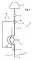
- Fig. 1shows a schematic representation of an embodiment of a measuring device 1 for determining a concentration of an analyte in a living body.
- the analyteis glucose.
- the measuring device 1comprises a sensor 2 for determining the concentration of an analyte in a liquid and a liquid delivery device having a liquid line 3 for connection to a body tissue implantable probe 4 and a pump 5 to pump liquid from the probe 4 through the liquid line 3 to the glucose sensor 2 ,
- the measuring device 1forms together with the probe 4, which in FIG. 1 implanted in a human body 6, a portable measuring system that is independent of the power supply.
- the sensor 2is an electrochemical sensor.
- the sensor 2is designed as a flow sensor.
- the liquid conveying deviceincludes a degassing device 10 for degassing the liquid to be supplied to the sensor 2 from the probe 4 via the liquid line 3.
- the degassing device 10comprises an in Fig. 1 Discharge line 11 shown in dashed lines, with which a negative pressure is applied to a gas-permeable surface of the liquid line 3 during operation.
- the gas-permeable surface of the liquid lineis arranged in a degassing chamber 12, to which the suction line 11 is connected.
- the gas permeable surface of the liquid conduit 3is provided by a hollow fiber which forms a portion of the liquid conduit disposed in the degassing chamber 12.
- Suitable hollow fibers with a gas-permeable, but liquid-tight surfaceare offered under the name Oxyphan or Oxyplus of Membrana.
- Suitable materials for such hollow fibersare, in particular, hydrophobic chain molecules, for example polypropylene and polymethylpentene.
- the fluid conduit 3comprises one Hose formed section 3a, on which the pump acts in operation to generate the delivery pressure peristaltic.
- the suction line 11comprises a section 11a in the form of a tube, onto which the pump 5 acts peristaltically in operation for generating the negative pressure.
- Peristaltic pumpsconsist essentially of a hose bed as a support for the hose and at least one element that squeezes the hose in a partial area. The pumping action is created by moving the squeeze element longitudinally relative to the tube.
- squeezing elementsram, fingers or rollers on a rotor are known. In the illustrated embodiment, three rollers are shown, which are moved along in the direction of arrow on the hose.
- the tube sections 3a, 11a of the liquid line 3 and the suction line 11are arranged side by side on a tube bed, so that the pinch elements of the peristaltic pump act on both tubes simultaneously. It is advantageous for the corresponding sections 3a, 11a of the liquid line 3 and the suction 11 to use the same tubes, in particular made of the same material, such as PVC, and with the same outer diameter.
- the tube-designed first section 3a of the liquid line 3, on which the pump 5 acts peristaltically to generate the delivery pressurehas a greater wall thickness than a second liquid line section 3b arranged in the degassing chamber 12.
- the first section 3a of the liquid line 3, on which the pump 5 for generating the delivery pressure acts peristalticallycan be made more resistant in this way, so that it can withstand the peristaltic action of the pump 5 for a long time without signs of wear.
- the second liquid line section 3b arranged in the degassing chamber 12is not subjected to such a stress, so that it can be made particularly thin-walled to provide the gas-permeable surface.
- the two sections 3a, 3b of the liquid lineare cohesively, for example, by gluing, connected to each other.
- the second section 3b of the liquid line 3is to ensure that the cavity of the degassing chamber 12 on the one hand long enough to allow sufficient to remove any gas bubbles gas passage, and on the other hand as short as possible, so that when commissioning as quickly as possible, the required negative pressure the degassing chamber 12 can generate.
- the optimum length of the degassing chamber 12therefore depends on the flow rate of the liquid in the liquid conduit 3 and on the inner diameter of the hose portion 11.
- the arranged in the degassing chamber 12 second liquid line section 3bpreferably has a wall thickness of less than 0.2 mm, in particular less than 0.1 mm.
- the first section 3a of the liquid line 3 designed as a tube, on which the pump 5 acts peristaltically to generate the delivery pressurepreferably has a wall thickness of at least 0.5 mm, in particular a wall thickness of 0.7 mm to 2 mm.
- the inner diameter of the tube, on which the pump 5 peristaltically acts,is preferably 0.5 mm to 0.3 mm.
- the arranged in the degassing chamber 12 second portion of the liquid linepreferably has an inner diameter of 0.1 mm to 0.4 mm, in particular 0.2 mm to 0.4 mm.
- the degassing chamber 12preferably has a length which is 5 to 50 times the inner diameter of the portion of the liquid line 3 extending in the degassing chamber 12.
- a volume of the cavity of the degassing chamber 12which is 1.2 to 1200 times the volume which is occupied in the cavity by the second section 3b of the liquid line 3 arranged therein.
- the degassing chamber 12is preferably formed as a plastic T-piece, so that the liquid line 3 with little effort through the degassing chamber 12th passed through and the suction line 11 can be connected to the degassing chamber 12.
- the measuring device showncan be constantly carried by a user, it is independent of the mains operable and therefore has a receptacle (not shown) for batteries.
- the mass of the measuring deviceis less than 1 kg, so that a user is burdened by their weight only slightly.
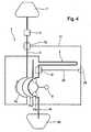
- FIG. 2schematically another embodiment of a measuring system is shown, comprising a measuring device 1 and a probe 4, which in Fig. 2 is shown implanted in a living body 6. While in the basis of Fig. 1 illustrated embodiment with the probe 4 taken a body fluid sample 1 and examined by means of the sensor 2, in the in Fig. 2 illustrated measuring system passed a perfusion through the trained as a microdialysis probe 4.
- the microdialysis probe 4has a dialysis membrane through which analyte molecules can diffuse out of the probe 4 surrounding body fluid into the perfusion fluid, so that the perfusion fluid can then be passed through the fluid line 3 to the sensor 2 for determining the analyte concentration.
- the measuring system shownis therefore a microdialysis system.
- Measuring device 1 shownhas a perfusion fluid line 14, which serves to conduct perfusion fluid from a perfusion fluid reservoir 20 into the microdialysis probe 4.
- a section 14a of the perfusion fluid line 14is formed as a hose on which the peristaltic pump 5 acts peristaltically to generate a delivery pressure.
- This hose section 14ais arranged in the hose bed of the pump 5 next to the hoses 3a, 11a of the suction line 11 and the liquid line 3, so that the squeezing elements of the peristaltic pump 5 act in common on all three hoses 3a, 11a, 14a.
- Suitable dialysis probes 4 and further details of the microdialysis systemare in the US 2002/0082490 A1 which is hereby incorporated by reference in the present application.
- the only essential difference between the in Fig. 2 shown measuring system and the from the US 2002/0082490 A1 known microdialysis systemis that in the illustrated embodiment, a liquid conveyor with a degassing device 11, 12 has been added to increase the reliability and accuracy of the information obtained with the sensor 2 on the analyte concentration.
- FIG. 3schematically another embodiment of a microdialysis system is shown.
- This in Fig. 3 shown microdialysis systemdiffers from that in Fig. 2 shown microdialysis system characterized in that a second degassing device with a second degassing chamber 21 for degassing to be introduced into the probe 4 perfusion liquid.
- the perfusion line 14passes through the second degassing chamber 21, to which a second vacuum line 22 is applied.
- the vacuum line 22also has a section formed as a tube 22a, on which the peristaltic pump 5 acts peristaltically to generate the negative pressure.
- the section 14a of the perfusion fluid line 14 extending in the second degassing chamber 21, like the corresponding second section 3a of the fluid line 3 running in the first degassing chamber 12,has a gas-permeable surface and may be formed, for example, as a hollow fiber.
- FIG. 4schematically another embodiment of a microdialysis system is shown.
- This in Fig. 4 shown microdialysis systemdiffers from that in Fig. 3 shown microdialysis system in that the vacuum line 11 and the vacuum line 22 are connected to each other with a T-piece 24, so that only a trained as a tube section 11a is required, on which the peristaltic pump 5 acts to generate the negative pressure peristaltic.
- Across from Fig. 3This results in the ability to reduce the required moment of the peristaltic pump 5 and thus their power consumption.
Landscapes
- Health & Medical Sciences (AREA)
- Life Sciences & Earth Sciences (AREA)
- Engineering & Computer Science (AREA)
- Physics & Mathematics (AREA)
- Medical Informatics (AREA)
- Animal Behavior & Ethology (AREA)
- Veterinary Medicine (AREA)
- Biophysics (AREA)
- Pathology (AREA)
- Public Health (AREA)
- Biomedical Technology (AREA)
- Heart & Thoracic Surgery (AREA)
- General Health & Medical Sciences (AREA)
- Molecular Biology (AREA)
- Surgery (AREA)
- Hematology (AREA)
- Optics & Photonics (AREA)
- Chemical & Material Sciences (AREA)
- Chemical Kinetics & Catalysis (AREA)
- Mechanical Engineering (AREA)
- General Engineering & Computer Science (AREA)
- Manufacturing & Machinery (AREA)
- General Chemical & Material Sciences (AREA)
- Emergency Medicine (AREA)
- Dermatology (AREA)
- Measurement Of The Respiration, Hearing Ability, Form, And Blood Characteristics Of Living Organisms (AREA)
- Investigating Or Analysing Biological Materials (AREA)
Abstract
Description
Translated fromGermanDie Erfindung betrifft eine tragbare Messeinrichtung zur Bestimmung einer Konzentration eines Analyten in einem lebenden Körper mit den im Oberbegriff des Anspruchs 1 angegebenen Merkmalen. Eine Messeinrichtung entsprechend dem Oberbegriff von Anspruch 1 ist aus der
Messeinrichtungen zur Bestimmung einer Konzentration eines Analyten in einem lebenden Körper sind im Stand der Technik insbesondere als so genannte Mikrodialysesysteme bekannt und in der
Wichtigste Anwendung von Mikrodialysesystemen ist die Messung der Glukosekonzentration zur Diabetesbehandlung. Die dafür verwendeten Messeinrichtungen müssen klein und leicht sein, da sie von Diabetikern ständig mitgeführt werden. Prinzipiell ist es zur kontinuierlichen Messung des Glukosegehalts mit einer tragbaren Messeinrichtung aber nicht erforderlich, dass eine Perfusionslösung durch eine Mikrodialysesonde hindurch gepumpt wird. Möglich ist es auch, mit einer Sonde kontinuierlich eine geringe Menge Körperflüssigkeit aus Körpergewebe zu entnehmen und mit einem Sensor die Konzentrationsbestimmung unmittelbar an der Körperflüssigkeit vorzunehmen.The most important application of microdialysis systems is the measurement of the glucose concentration for the treatment of diabetes. The used for it Measuring equipment must be small and light, as they are constantly carried by diabetics. In principle, however, it is not necessary for the continuous measurement of the glucose content with a portable measuring device that a perfusion solution is pumped through a microdialysis probe. It is also possible to continuously remove a small amount of body fluid from body tissue with a probe and to carry out a concentration determination directly on the body fluid with a sensor.
Tragbare Messeinrichtung der eingangs genannten Art müssen einerseits möglichst klein und leicht sein, um von einem Patienten ständig mitgeführt werden zu können, andererseits eine medizinisch bedeutsame Analytkonzentration zuverlässig und mit hoher Präzision bestimmen.Portable measuring device of the type mentioned must firstly be as small and light as possible to be constantly carried by a patient can, on the other hand, determine a medically significant analyte concentration reliably and with high precision.
Aufgabe der Erfindung ist es deshalb einen Weg aufzuzeigen, wie bei einer tragbaren Messeinrichtung der eingangs genannten Art die Messgenauigkeit verbessert werden kann, ohne Größe und Gewicht der Messeinrichtung wesentlich zu erhöhen.The object of the invention is therefore to show a way, as in a portable measuring device of the type mentioned in the measurement accuracy can be improved without increasing the size and weight of the measuring device significantly.
Diese Aufgabe wird erfindungsgemäß mit einer tragbaren Messeinrichtung der eingangs genannten Art, dadurch gelöst, dass die Flüssigkeits-Fördereinrichtung eine Entgasungseinrichtung zum Entgasen der dem Sensor von der Sonde über die Flüssigkeitsleitung zuzuführenden Flüssigkeit umfasst.This object is achieved with a portable measuring device of the type mentioned, characterized in that the liquid conveyor comprises a degassing device for degassing the sensor to be supplied by the probe via the liquid line liquid.
Im Rahmen der Erfindung wurde festgestellt, dass die Messgenauigkeit durch Schwankungen des Gasgehalts der zu analysierenden Flüssigkeit, insbesondere durch darin auftretende Gasblasen, beeinträchtigt wird. Durch Entgasen der zu analysierenden Flüssigkeit lässt sich deshalb die Messgenauigkeit wesentlich steigern. Um eine bedeutende Verbesserung gegenüber dem Stand der Technik zu erzielen, ist es dabei nicht unbedingt erforderlich, dass die zu untersuchende Flüssigkeit vollständig entgast wird, da bereits durch das Entfernen von Gasblasen die Präzision und Zuverlässigkeit von Messergebnissen der Analytkonzentration erheblich gesteigert werden kann.In the context of the invention, it has been found that the measurement accuracy is impaired by fluctuations in the gas content of the liquid to be analyzed, in particular by gas bubbles occurring therein. By degassing the liquid to be analyzed, therefore, the measurement accuracy can be significantly increased. In order to achieve a significant improvement over the prior art, it is not absolutely necessary that the liquid to be examined is completely degassed, since already by the removal of gas bubbles, the precision and reliability of measurement results of the analyte concentration can be significantly increased.
Um mit tragbaren Messeinrichtungen eine medizinisch bedeutsame Analytkonzentration bestimmen zu können, sind neben der eigentlichen Messeinrichtung verschiedene Verbrauchsmaterialen erforderlich, beispielsweise Sonden, die bestimmungsgemäß in Körpergewebe implantiert werden, und Schläuche zum Anschluss einer Sonde an die Flüssigkeitsleitung der Messeinrichtung. Derartige Verbrauchsmaterialen und eine dazugehörende Messeinrichtung bilden ein tragbares Messsystem zur Bestimmung einer Analytkonzentration. Ein weiterer Aspekt der Erfindung betrifft deshalb ein tragbares Messsystem zur Bestimmung einer medizinisch bedeutsamen Analytkonzentration mit einer erfindungsgemäßen Messeinrichtung, die einen Sensor und eine Flüssigkeitsfördereinrichtung umfasst, und eine in Körpergewebe implantierbare Sonde, die im Betrieb an die Flüssigkeitsfördereinrichtung angeschlossen ist.In order to be able to determine a medically significant analyte concentration using portable measuring devices, various consumables are required in addition to the actual measuring device, for example probes that are intended to be implanted in body tissue, and tubes for connecting a probe to the liquid line of the measuring device. Such consumables and an associated measuring device form a portable measuring system for determining an analyte concentration. A further aspect of the invention therefore relates to a portable measuring system for determining a medically significant analyte concentration with a measuring device according to the invention comprising a sensor and a liquid delivery device, and a probe implantable in body tissue which is connected in operation to the liquid delivery device.
Die Entgasungseinrichtung der erfindungsgemäßen Messeinrichtung umfasst eine Absaugleitung, mit der im Betrieb ein Unterdruck an eine gasdurchlässige Oberfläche der Flüssigkeitsleitung angelegt wird. Beispielsweise kann ein Abschnitt der Flüssigkeitsleitung als gasdurchlässige Hohlfaser ausgebildet werden, die in einer Entgasungskammer angeordnet ist, an welche die Absaugleitung angeschlossen ist. Besonders günstig ist es dabei, dass die Flüssigkeitsleitung einen als Schlauch ausgebildeten Abschnitt umfasst, auf den die Pumpe zum Erzeugen eines Förderdrucks peristaltisch einwirkt und die Absaugleitung ebenfalls einen als Schlauch ausgebildeten Abschnitt umfasst, auf den die Pumpe zum Erzeugen des Unterdrucks peristaltisch einwirkt. Auf diese Weise kann mit einer einzigen Pumpe, die für eine Flüssigkeitsfördereinrichtung ohnehin benötigt wird, sowohl der erforderliche Förderdruck als auch der Unterdruck erzeugt werden und mit einem kompakten Gerät eine Entgasung der zu analysierenden Flüssigkeit bewirkt werden.The degassing device of the measuring device according to the invention comprises a suction line, with which during operation a negative pressure is applied to a gas-permeable surface of the liquid line. For example, a portion of the liquid conduit may be formed as a gas-permeable hollow fiber disposed in a degassing chamber to which the suction conduit is connected. It is particularly advantageous that the liquid line comprises a section formed as a tube on which the pump acts peristaltically to generate a delivery pressure and the suction line also comprises a section formed as a tube on which the pump acts to generate the negative pressure peristaltic. In this way, with a single pump, which is required anyway for a liquid conveyor, both the required delivery pressure and the negative pressure can be generated and a degassing of the liquid to be analyzed can be effected with a compact device.
Dokument
Peristaltikpumpen sind aus anderen Bereichen der Technik bekannt und beispielsweise in der
Weitere Einzelheiten und Vorteile der Erfindung werden im Folgenden im Rahmen von Ausführungsbeispielen unter Bezugnahme auf die beigefügten Zeichnungen erläutert, wobei gleiche und einander entsprechende Teile mit identischem Bezugszeichen gekennzeichnet sind. Die Merkmale der im Folgenden beschriebenen Ausführungsbeispiele können einzeln oder in Kombination zum Gegenstand von Ansprüchen gemacht werden. Es zeigen:
- Fig. 1
- eine schematische Darstellung eines Ausführungsbeispiels einer erfindungsgemäßen Messeinrichtung;
- Fig. 2
- eine schematische Darstellung eines weiteren Ausführungsbeispiels einer erfindungsgemäßen Messeinrichtung;
- Fig. 3
- eine schematische Darstellung eines weiteren Ausführungsbeispiels einer erfindungsgemäßen Messeinrichtung; und
- Fig. 4
- eine schematische Darstellung eines weiteren Ausführungsbeispiels einer erfindungsgemäßen Messeinrichtung.
- Fig. 1
- a schematic representation of an embodiment of a measuring device according to the invention;
- Fig. 2
- a schematic representation of another embodiment of a measuring device according to the invention;
- Fig. 3
- a schematic representation of another embodiment of a measuring device according to the invention; and
- Fig. 4
- a schematic representation of another embodiment of a measuring device according to the invention.
Mit der Pumpe 5 wird bei dem in
Bei der Pumpe 5 handelt es sich um eine Peristaltikpumpe, mit der sowohl der Förderdruck der Flüssigkeitsleitung 3 als auch der Unterdruck der Absaugleitung 11 erzeugt wird. Die Flüssigkeitsleitung 3 umfasst einen als Schlauch ausgebildeten Abschnitt 3a, auf den die Pumpe im Betrieb zum Erzeugen des Förderdrucks peristaltisch einwirkt. Die Absaugleitung 11 umfasst einen als Schlauch ausgebildeten Abschnitt 11a, auf den die Pumpe 5 im Betrieb zum Erzeugen des Unterdrucks peristaltisch einwirkt.In the
Peristaltikpumpen bestehen im Wesentlichen aus einem Schlauchbett als Auflage für den Schlauch und mindestens einem Element, das den Schlauch in einem Teilbereich quetscht. Die Pumpwirkung wird erzeugt, in dem das Quetschelement relativ zum Schlauch in Längsrichtung bewegt wird. Als Quetschelemente sind Stößel, Finger oder Rollen auf einem Rotor bekannt. Bei dem dargestellten Ausführungsbeispiel sind drei Rollen dargestellt, die in Pfeilrichtung an dem Schlauch entlangbewegt werden. Die Schlauchabschnitte 3a, 11a der Flüssigkeitsleitung 3 und der Absaugleitung 11 sind nebeneinander auf einem Schlauchbett angeordnet, so dass die Quetschelemente der Peristaltikpumpe jeweils auf beide Schläuche gleichzeitig einwirken. Dabei ist es günstig, für die entsprechenden Abschnitte 3a, 11a der Flüssigkeitsleitung 3 und der Absaugleitung 11 gleiche Schläuche, insbesondere aus gleichem Material, beispielsweise PVC, und mit gleichem Außendurchmesser, zu verwenden.Peristaltic pumps consist essentially of a hose bed as a support for the hose and at least one element that squeezes the hose in a partial area. The pumping action is created by moving the squeeze element longitudinally relative to the tube. As squeezing elements ram, fingers or rollers on a rotor are known. In the illustrated embodiment, three rollers are shown, which are moved along in the direction of arrow on the hose. The
Günstig ist es, wenn der als Schlauch ausgebildete erste Abschnitt 3a der Flüssigkeitsleitung 3, auf den die Pumpe 5 zum Erzeugen des Förderdrucks peristaltisch einwirkt, eine größere Wandstärke als ein in der Entgasungskammer 12 angeordneter zweiter Flüssigkeitsleitungsabschnitt 3b hat. Der erste Abschnitt 3a der Flüssigkeitsleitung 3, auf den die Pumpe 5 zum Erzeugen des Förderdrucks peristaltisch einwirkt, kann auf diese Weise widerstandsfähiger ausgebildet werden, so dass er der peristaltischen Einwirkung der Pumpe 5 lange Zeit ohne Verschleißerscheinungen standhalten kann. Der in der Entgasungskammer 12 angeordnete zweite Flüssigkeitsleitungsabschnitt 3b ist jedoch keiner derartigen Beanspruchung ausgesetzt, so dass er besonders dünnwandig ausgeführt werden kann, um die gasdurchlässige Oberfläche zur Verfügung zu stellen. Die beiden Abschnitte 3a, 3b der Flüssigkeitsleitung sind stoffschlüssig, beispielsweise durch kleben, miteinander verbunden. Bei der Dimensionierung des Hohlraumes der Entgasungskammer 12 und des darin verlaufenden zweiten Abschnitts 3b der Flüssigkeitsleitung 3 ist darauf zu achten, dass der Hohlraum der Entgasungskammer 12 einerseits lang genug ist, um einen zum Entfernen evtl. Gasblasen ausreichenden Gasdurchtritt zu ermöglichen, und andererseits möglichst kurz ist, damit sich bei Inbetriebnahme möglichst schnell der erforderliche Unterdruck in der Entgasungskammer 12 erzeugen lässt. Die optimale Länge der Entgasungskammer 12 hängt deshalb von der Fließgeschwindigkeit der Flüssigkeit in der Flüssigkeitsleitung 3 und vom Innendurchmesser des Schlauchabschnitts 11 ab. Günstig sind Förderleistungen und Flüssigkeits-Fördereinrichtung von 0,1 µl/min bis 1 µl/min, insbesondere 0,2 µl/min bis 0,4 µl/min. Ferner ist darauf zu achten, dass das Volumen des Hohlraumes der Entgasungskammer 12, das den Abschnitt 3b der Flüssigkeitsleitung 3 umgibt, so groß ausgelegt ist, dass im Betrieb der relative Feuchtegehalt im Hohlraum gering gehalten wird und der erforderliche Unterdruck aufrecht erhalten werden kann.It is advantageous if the tube-designed
Der in der Entgasungskammer 12 angeordnete zweite Flüssigkeitsleitungsabschnitt 3b hat bevorzugt eine Wandstärke von weniger als 0,2 mm, insbesondere weniger als 0,1 mm. Der als Schlauch ausgebildete erste Abschnitt 3a der Flüssigkeitsleitung 3, auf den die Pumpe 5 zum Erzeugen des Förderdrucks peristaltisch einwirkt, hat bevorzugt eine Wandstärke von mindestens 0,5 mm, insbesondere eine Wandstärke von 0,7 mm bis 2 mm. Der Innendurchmesser des Schlauchs, auf den die Pumpe 5 peristaltisch einwirkt, beträgt bevorzugt 0,5 mm bis 0,3 mm. Der in der Entgasungskammer 12 angeordnete zweite Abschnitt der Flüssigkeitsleitung hat bevorzugt einen Innendurchmesser von 0,1 mm bis 0,4 mm, insbesondere 0,2 mm bis 0,4 mm. Die Entgasungskammer 12 hat bevorzugt eine Länge, die das 5- bis 50-fache des Innendurchmessers der in der Entgasungskammer 12 verlaufenden Abschnitts der Flüssigkeitsleitung 3 beträgt. Günstig ist ein Volumen des Hohlraums der Entgasungskammer 12, der das 1,2 bis 1200-fache des Volumens beträgt, welches im Hohlraum durch den darin angeordneten zweiten Abschnitt 3b der Flüssigkeitsleitung 3 eingenommen wird. Die Entgasungskammer 12 ist bevorzugt als T-Stück aus Kunststoff ausgebildet, so dass die Flüssigkeitsleitung 3 mit geringem Aufwand durch die Entgasungskammer 12 hindurchgeführt und die Absaugleitung 11 an die Entgasungskammer 12 angeschlossen werden kann.The arranged in the
Damit die dargestellte Messeinrichtung von einem Benutzer ständig mitgeführt werden kann, ist sie netzunabhängig betreibbar und hat deshalb ein Aufnahmefach (nicht dargestellt) für Batterien. Die Masse der Messeinrichtung beträgt weniger als 1 kg, so dass ein Benutzer durch deren Gewicht nur wenig belastet ist.So that the measuring device shown can be constantly carried by a user, it is independent of the mains operable and therefore has a receptacle (not shown) for batteries. The mass of the measuring device is less than 1 kg, so that a user is burdened by their weight only slightly.
In
Die in
Geeignete Dialysesonden 4 und weitere Einzelheiten des Mikrodialysesystems sind in der
In
In
- 11
- Tragbare MesseinrichtungPortable measuring device
- 22
- Sensorsensor
- 33
- Flüssigkeitsleitungliquid line
- 3a3a
- erster Abschnitt der Flüssigkeitsleitungfirst section of the fluid line
- 3b3b
- zweiter Abschnitt der Flüssigkeitsleitungsecond section of the liquid line
- 44
- Sondeprobe
- 55
- Peristaltikpumpeperistaltic pump
- 66
- Hautoberflächeskin surface
- 77
- Abfallbehälterwaste container
- 1010
- Entgasungseinrichtungdegassing
- 1111
- Absaugleitungsuction
- 11a11a
- Abschnitt der AbsaugleitungSection of the suction line
- 1212
- Entgasungskammerdegassing chamber
- 1414
- PerfusionsflüssigkeitsleitungPerfusionsflüssigkeitsleitung
- 14a14a
- Abschnitt der PerfusionsflüssigkeitsleitungSection of the perfusion fluid line
- 2020
- PerfusionsflüssigkeitsreservoirPerfusionsflüssigkeitsreservoir
- 2121
- Entgasungskammerdegassing chamber
- 2222
- Absaugleitungsuction
- 22a22a
- Abschnitt der Unterdruckleitung 22Section of the
vacuum line 22 - 2424
- T-StückTee
Claims (9)
- Portable measuring facility for determining the concentration of an analyte in a living body, comprisinga sensor (2) for determining the concentration of an analyte that is present in a liquid anda liquid conveying facility havinga liquid line (3) for connection to a probe (4) that can be implanted into body tissue, anda pump (5) in order to pump liquid from the probe (4) through the liquid line (3) to the sensor (2),a degassing facility (10) for degassing the liquid that is to be guided from the probe (4) through the liquid line (3) to the sensor (2), wherein the degassing facility (10) comprises an aspiration line (11) that is used, in operation, to apply a negative pressure to a gas-permeable surface (3b) of the liquid line (3),
characterized in thatthe pump (5) is a peristaltic pump,the liquid line (3) comprises a section (3a) that is provided in the form of a tube on which the pump (5), in operation, acts in a peristaltic fashion in order to generate a conveying pressure, andthe aspiration line (11) comprises a section (11a) that is provided in the form of a tube on which the pump (5), in operation, acts in a peristaltic fashion in order to generate the negative pressure. - Measuring facility according to claim 1,characterized in that the mass of the measuring facility (4) is less than 1 kg.
- Measuring facility according to any one of the preceding claims,characterized in that the gas-permeable surface of the liquid line (3) is arranged within a degassing chamber (12) to which the aspiration line (11) is connected.
- Measuring facility according to any one of the preceding claims,characterized in that the wall thickness of the first section (3a) of the liquid line (3) that is provided in the form of a tube and on which the pump (5) acts in a peristaltic fashion in order to generate the conveying pressure is larger than that of a second liquid line section (3b) having the gas-permeable surface that is arranged within the degassing chamber (12).
- Measuring facility according to claim 4,characterized in that the second section (3b) of the liquid line (3) is provided in the form of a hollow fiber.
- Measuring facility according to claim 4 or 5,characterized in that the length of the degassing chamber (12) is 5- to 20-fold the internal diameter of the section (3b) of the liquid line (3) that extends within the degassing chamber (12).
- Portable measuring system for determining a medically-significant analyte concentration, comprisinga measuring facility (1) according to any one of the preceding claims that comprises a sensor (2) and a liquid conveying facility, anda probe (4) that can be implanted in body tissue and, in operation, is connected to the liquid conveying facility.
- Measuring system according to claim 7,characterized by a perfusion liquid reservoir (20) and in that the measuring facility (1) is a micro-dialysis facility having a perfusion liquid line (14) that serves to guide perfusion liquid from the perfusion liquid reservoir (20) into a probe (4) that is provided in the form of a micro-dialysis probe and comprises a dialysis membrane through which analyte molecules from body fluid surrounding the probe (4) can diffuse into the perfusion liquid such that the perfusion liquid can subsequently be guided through the liquid line (3) to the sensor (2) for determining the analyte concentration.
- Liquid conveying facility for the degassing of liquids, in particular for a measuring facility (1) according to any one of the claims 1 to 7, comprisinga liquid line (3) for conveying the liquid,a pump (5) for generating a conveying pressure in the liquid line (3), andan aspiration line (11) that is used, in operation, to apply a negative pressure to a gas-permeable surface (3b) of the liquid line (3),
whereinthe pump (5) is a peristaltic pump,the liquid line (3) comprises a section (3a) that is provided in the form of a tube on which the pump (5), in operation, acts in a peristaltic fashion in order to generate the conveying pressure, andthe aspiration line (11) comprises a section (11a) that is provided in the form of a tube on which the pump (5), in operation, acts in a peristaltic fashion in order to generate the negative pressure.
Priority Applications (3)
| Application Number | Priority Date | Filing Date | Title |
|---|---|---|---|
| DE502006003267TDE502006003267D1 (en) | 2006-07-22 | 2006-07-22 | Portable measuring device for determining a medically important analyte concentration |
| EP06015295AEP1880669B1 (en) | 2006-07-22 | 2006-07-22 | Portable medical device for measuring analyte concentration |
| AT06015295TATE426358T1 (en) | 2006-07-22 | 2006-07-22 | PORTABLE MEASURING DEVICE FOR DETERMINING A MEDICALLY SIGNIFICANT ANALYTE CONCENTRATION |
Applications Claiming Priority (1)
| Application Number | Priority Date | Filing Date | Title |
|---|---|---|---|
| EP06015295AEP1880669B1 (en) | 2006-07-22 | 2006-07-22 | Portable medical device for measuring analyte concentration |
Publications (2)
| Publication Number | Publication Date |
|---|---|
| EP1880669A1 EP1880669A1 (en) | 2008-01-23 |
| EP1880669B1true EP1880669B1 (en) | 2009-03-25 |
Family
ID=37682693
Family Applications (1)
| Application Number | Title | Priority Date | Filing Date |
|---|---|---|---|
| EP06015295ANot-in-forceEP1880669B1 (en) | 2006-07-22 | 2006-07-22 | Portable medical device for measuring analyte concentration |
Country Status (3)
| Country | Link |
|---|---|
| EP (1) | EP1880669B1 (en) |
| AT (1) | ATE426358T1 (en) |
| DE (1) | DE502006003267D1 (en) |
Families Citing this family (3)
| Publication number | Priority date | Publication date | Assignee | Title |
|---|---|---|---|---|
| EP2180317A1 (en) | 2008-10-24 | 2010-04-28 | Roche Diagnostics GmbH | System for measuring the concentration of an analyte and method of monitoring a flow of liquid. |
| WO2017129192A1 (en) | 2016-01-25 | 2017-08-03 | Fluisense Aps | Micro dosage peristaltic pump for micro dosage of fluid |
| CN108474375B (en) | 2016-01-25 | 2021-07-02 | 弗卢森塞有限公司 | Micro-dose peristaltic pump for micro-dosed fluids |
Family Cites Families (6)
| Publication number | Priority date | Publication date | Assignee | Title |
|---|---|---|---|---|
| FR2574664B1 (en)* | 1984-12-14 | 1987-03-06 | Issautier Gerald | HEMODIALYSIS DEVICE FOR AUTOMATICALLY CONTROLLING WEIGHT LOSS |
| US5002054A (en)* | 1987-02-25 | 1991-03-26 | Ash Medical Systems, Inc. | Interstitial filtration and collection device and method for long-term monitoring of physiological constituents of the body |
| GB9320850D0 (en)* | 1993-10-09 | 1993-12-01 | Terwee Thomas H M | Monitoring the concentration of a substance or a group of substances in a body fluid of a human or an animal |
| EP0649628B1 (en)* | 1993-10-22 | 1999-01-07 | Siemens-Elema AB | Processes and devices for continuously monitoring levels of anolyte |
| DE19848112C2 (en)* | 1998-10-19 | 2001-12-13 | Meinhard Knoll | Minimally invasive sensor system |
| AU2002241567A1 (en)* | 2000-11-30 | 2002-07-24 | Biovalve Technologies, Inc. | Fluid delivery and measurement systems and methods |
- 2006
- 2006-07-22ATAT06015295Tpatent/ATE426358T1/ennot_activeIP Right Cessation
- 2006-07-22EPEP06015295Apatent/EP1880669B1/ennot_activeNot-in-force
- 2006-07-22DEDE502006003267Tpatent/DE502006003267D1/ennot_activeExpired - Fee Related
Also Published As
| Publication number | Publication date |
|---|---|
| ATE426358T1 (en) | 2009-04-15 |
| EP1880669A1 (en) | 2008-01-23 |
| DE502006003267D1 (en) | 2009-05-07 |
Similar Documents
| Publication | Publication Date | Title |
|---|---|---|
| EP1177759B1 (en) | Microdialysis device | |
| DE2734247C2 (en) | Device for continuous chemical analysis in the living body | |
| AT393213B (en) | DEVICE FOR DETERMINING AT LEAST ONE MEDICAL MEASURING SIZE | |
| EP0534074B1 (en) | Method and instrument for testing the concentration of body fluid constituents | |
| DE60116351T2 (en) | DEVICE FOR REMOVING INTERSTITIAL FLUID OF A PATIENT FOR DIAGNOSTIC TESTS | |
| DE69523887T2 (en) | CLOSED BLOOD SAMPLING DEVICE | |
| EP1129778A2 (en) | System for determining the concentration of an analyte in body fluids | |
| AT412060B (en) | METHOD FOR MEASURING CONCENTRATIONS IN LIVING ORGANISMS BY MEANS OF MICRODIALYSIS AND AND DEVICE FOR IMPLEMENTING THIS METHOD | |
| WO2006087236A1 (en) | Catheter with microchannels for monitoring the concentration of an analyte in a bodily fluid | |
| EP0367752B1 (en) | Device for determining the concentration of at least one substance in living tissue | |
| DE10105549A1 (en) | System for monitoring the concentration of analytes in body fluids | |
| DE10003507B4 (en) | Device and method for the removal of liquids from the body's own tissue and determination of substance concentrations in this liquid | |
| DE4401400A1 (en) | Method and arrangement for continuously monitoring the concentration of a metabolite | |
| EP2091412B1 (en) | Sample taking device, and sample taking methods | |
| DE2907787A1 (en) | METHOD FOR QUICKLY TRANSFERRING A LOW PRESSURE GAS, IN PARTICULAR BLOOD GAS COMING FROM A BLOOD VESSEL, TO A GAS ANALYZER, AND DEVICE FOR PERFORMING THE METHOD | |
| EP1123040A1 (en) | Minimally invasive sensor system | |
| WO2010103051A1 (en) | Sampling device and sampling method | |
| EP3159026A1 (en) | Intermediate element for a medical extracorporeal fluid conduit, medical extracorporeal fluid system and method for measuring a gas contained in a fluid guided in a medical extracorporeal fluid system of the human or animal body | |
| EP1880669B1 (en) | Portable medical device for measuring analyte concentration | |
| EP0973573B1 (en) | Catheter for measuring chemical parameters, in particular for introducing into biological tissues, liquids or the like | |
| EP1870033A1 (en) | Devices and method for detecting an analyte | |
| DE10140565A1 (en) | Device for gas or liquid separation from microfluidic flow systems | |
| WO2020053212A1 (en) | System for analysing fluids originating from the body or fluids in contact with fluids originating from the body | |
| DE10340012A1 (en) | Device for gas or liquid separation from microfluidic flow systems | |
| EP2405802A1 (en) | Sampling device and sampling method |
Legal Events
| Date | Code | Title | Description |
|---|---|---|---|
| PUAI | Public reference made under article 153(3) epc to a published international application that has entered the european phase | Free format text:ORIGINAL CODE: 0009012 | |
| AK | Designated contracting states | Kind code of ref document:A1 Designated state(s):AT BE BG CH CY CZ DE DK EE ES FI FR GB GR HU IE IS IT LI LT LU LV MC NL PL PT RO SE SI SK TR | |
| AX | Request for extension of the european patent | Extension state:AL BA HR MK YU | |
| 17P | Request for examination filed | Effective date:20080213 | |
| 17Q | First examination report despatched | Effective date:20080411 | |
| AKX | Designation fees paid | Designated state(s):AT BE BG CH CY CZ DE DK EE ES FI FR GB GR HU IE IS IT LI LT LU LV MC NL PL PT RO SE SI SK TR | |
| GRAP | Despatch of communication of intention to grant a patent | Free format text:ORIGINAL CODE: EPIDOSNIGR1 | |
| GRAP | Despatch of communication of intention to grant a patent | Free format text:ORIGINAL CODE: EPIDOSNIGR1 | |
| GRAS | Grant fee paid | Free format text:ORIGINAL CODE: EPIDOSNIGR3 | |
| GRAA | (expected) grant | Free format text:ORIGINAL CODE: 0009210 | |
| AK | Designated contracting states | Kind code of ref document:B1 Designated state(s):AT BE BG CH CY CZ DE DK EE ES FI FR GB GR HU IE IS IT LI LT LU LV MC NL PL PT RO SE SI SK TR | |
| REG | Reference to a national code | Ref country code:GB Ref legal event code:FG4D Free format text:NOT ENGLISH | |
| REG | Reference to a national code | Ref country code:CH Ref legal event code:EP | |
| REG | Reference to a national code | Ref country code:IE Ref legal event code:FG4D Free format text:LANGUAGE OF EP DOCUMENT: GERMAN | |
| REF | Corresponds to: | Ref document number:502006003267 Country of ref document:DE Date of ref document:20090507 Kind code of ref document:P | |
| PG25 | Lapsed in a contracting state [announced via postgrant information from national office to epo] | Ref country code:SI Free format text:LAPSE BECAUSE OF FAILURE TO SUBMIT A TRANSLATION OF THE DESCRIPTION OR TO PAY THE FEE WITHIN THE PRESCRIBED TIME-LIMIT Effective date:20090325 Ref country code:FI Free format text:LAPSE BECAUSE OF FAILURE TO SUBMIT A TRANSLATION OF THE DESCRIPTION OR TO PAY THE FEE WITHIN THE PRESCRIBED TIME-LIMIT Effective date:20090325 Ref country code:LT Free format text:LAPSE BECAUSE OF FAILURE TO SUBMIT A TRANSLATION OF THE DESCRIPTION OR TO PAY THE FEE WITHIN THE PRESCRIBED TIME-LIMIT Effective date:20090325 | |
| PG25 | Lapsed in a contracting state [announced via postgrant information from national office to epo] | Ref country code:PL Free format text:LAPSE BECAUSE OF FAILURE TO SUBMIT A TRANSLATION OF THE DESCRIPTION OR TO PAY THE FEE WITHIN THE PRESCRIBED TIME-LIMIT Effective date:20090325 Ref country code:LV Free format text:LAPSE BECAUSE OF FAILURE TO SUBMIT A TRANSLATION OF THE DESCRIPTION OR TO PAY THE FEE WITHIN THE PRESCRIBED TIME-LIMIT Effective date:20090325 Ref country code:SE Free format text:LAPSE BECAUSE OF FAILURE TO SUBMIT A TRANSLATION OF THE DESCRIPTION OR TO PAY THE FEE WITHIN THE PRESCRIBED TIME-LIMIT Effective date:20090625 | |
| REG | Reference to a national code | Ref country code:IE Ref legal event code:FD4D | |
| PG25 | Lapsed in a contracting state [announced via postgrant information from national office to epo] | Ref country code:CZ Free format text:LAPSE BECAUSE OF FAILURE TO SUBMIT A TRANSLATION OF THE DESCRIPTION OR TO PAY THE FEE WITHIN THE PRESCRIBED TIME-LIMIT Effective date:20090325 Ref country code:PT Free format text:LAPSE BECAUSE OF FAILURE TO SUBMIT A TRANSLATION OF THE DESCRIPTION OR TO PAY THE FEE WITHIN THE PRESCRIBED TIME-LIMIT Effective date:20090831 Ref country code:EE Free format text:LAPSE BECAUSE OF FAILURE TO SUBMIT A TRANSLATION OF THE DESCRIPTION OR TO PAY THE FEE WITHIN THE PRESCRIBED TIME-LIMIT Effective date:20090325 Ref country code:ES Free format text:LAPSE BECAUSE OF FAILURE TO SUBMIT A TRANSLATION OF THE DESCRIPTION OR TO PAY THE FEE WITHIN THE PRESCRIBED TIME-LIMIT Effective date:20090706 | |
| PGFP | Annual fee paid to national office [announced via postgrant information from national office to epo] | Ref country code:FR Payment date:20090708 Year of fee payment:4 | |
| PG25 | Lapsed in a contracting state [announced via postgrant information from national office to epo] | Ref country code:RO Free format text:LAPSE BECAUSE OF FAILURE TO SUBMIT A TRANSLATION OF THE DESCRIPTION OR TO PAY THE FEE WITHIN THE PRESCRIBED TIME-LIMIT Effective date:20090325 Ref country code:IS Free format text:LAPSE BECAUSE OF FAILURE TO SUBMIT A TRANSLATION OF THE DESCRIPTION OR TO PAY THE FEE WITHIN THE PRESCRIBED TIME-LIMIT Effective date:20090725 Ref country code:SK Free format text:LAPSE BECAUSE OF FAILURE TO SUBMIT A TRANSLATION OF THE DESCRIPTION OR TO PAY THE FEE WITHIN THE PRESCRIBED TIME-LIMIT Effective date:20090325 | |
| PGFP | Annual fee paid to national office [announced via postgrant information from national office to epo] | Ref country code:DE Payment date:20090730 Year of fee payment:4 Ref country code:NL Payment date:20090722 Year of fee payment:4 | |
| PG25 | Lapsed in a contracting state [announced via postgrant information from national office to epo] | Ref country code:BG Free format text:LAPSE BECAUSE OF FAILURE TO SUBMIT A TRANSLATION OF THE DESCRIPTION OR TO PAY THE FEE WITHIN THE PRESCRIBED TIME-LIMIT Effective date:20090625 Ref country code:DK Free format text:LAPSE BECAUSE OF FAILURE TO SUBMIT A TRANSLATION OF THE DESCRIPTION OR TO PAY THE FEE WITHIN THE PRESCRIBED TIME-LIMIT Effective date:20090325 Ref country code:IE Free format text:LAPSE BECAUSE OF FAILURE TO SUBMIT A TRANSLATION OF THE DESCRIPTION OR TO PAY THE FEE WITHIN THE PRESCRIBED TIME-LIMIT Effective date:20090325 | |
| PLBE | No opposition filed within time limit | Free format text:ORIGINAL CODE: 0009261 | |
| STAA | Information on the status of an ep patent application or granted ep patent | Free format text:STATUS: NO OPPOSITION FILED WITHIN TIME LIMIT | |
| BERE | Be: lapsed | Owner name:ROCHE DIAGNOSTICS G.M.B.H. Effective date:20090731 Owner name:F.HOFFMANN-LA ROCHE A.G. Effective date:20090731 | |
| PG25 | Lapsed in a contracting state [announced via postgrant information from national office to epo] | Ref country code:MC Free format text:LAPSE BECAUSE OF NON-PAYMENT OF DUE FEES Effective date:20090731 | |
| 26N | No opposition filed | Effective date:20091229 | |
| PG25 | Lapsed in a contracting state [announced via postgrant information from national office to epo] | Ref country code:BE Free format text:LAPSE BECAUSE OF NON-PAYMENT OF DUE FEES Effective date:20090731 | |
| PG25 | Lapsed in a contracting state [announced via postgrant information from national office to epo] | Ref country code:GR Free format text:LAPSE BECAUSE OF FAILURE TO SUBMIT A TRANSLATION OF THE DESCRIPTION OR TO PAY THE FEE WITHIN THE PRESCRIBED TIME-LIMIT Effective date:20090626 | |
| PG25 | Lapsed in a contracting state [announced via postgrant information from national office to epo] | Ref country code:AT Free format text:LAPSE BECAUSE OF NON-PAYMENT OF DUE FEES Effective date:20090722 | |
| REG | Reference to a national code | Ref country code:NL Ref legal event code:V1 Effective date:20110201 | |
| REG | Reference to a national code | Ref country code:CH Ref legal event code:PL | |
| GBPC | Gb: european patent ceased through non-payment of renewal fee | Effective date:20100722 | |
| PG25 | Lapsed in a contracting state [announced via postgrant information from national office to epo] | Ref country code:IT Free format text:LAPSE BECAUSE OF FAILURE TO SUBMIT A TRANSLATION OF THE DESCRIPTION OR TO PAY THE FEE WITHIN THE PRESCRIBED TIME-LIMIT Effective date:20090325 | |
| REG | Reference to a national code | Ref country code:FR Ref legal event code:ST Effective date:20110331 | |
| PG25 | Lapsed in a contracting state [announced via postgrant information from national office to epo] | Ref country code:LU Free format text:LAPSE BECAUSE OF NON-PAYMENT OF DUE FEES Effective date:20090722 Ref country code:DE Free format text:LAPSE BECAUSE OF NON-PAYMENT OF DUE FEES Effective date:20110201 Ref country code:CH Free format text:LAPSE BECAUSE OF NON-PAYMENT OF DUE FEES Effective date:20100731 Ref country code:LI Free format text:LAPSE BECAUSE OF NON-PAYMENT OF DUE FEES Effective date:20100731 | |
| REG | Reference to a national code | Ref country code:DE Ref legal event code:R119 Ref document number:502006003267 Country of ref document:DE Effective date:20110201 | |
| PG25 | Lapsed in a contracting state [announced via postgrant information from national office to epo] | Ref country code:FR Free format text:LAPSE BECAUSE OF NON-PAYMENT OF DUE FEES Effective date:20100802 Ref country code:NL Free format text:LAPSE BECAUSE OF NON-PAYMENT OF DUE FEES Effective date:20110201 | |
| PG25 | Lapsed in a contracting state [announced via postgrant information from national office to epo] | Ref country code:HU Free format text:LAPSE BECAUSE OF FAILURE TO SUBMIT A TRANSLATION OF THE DESCRIPTION OR TO PAY THE FEE WITHIN THE PRESCRIBED TIME-LIMIT Effective date:20090926 | |
| PG25 | Lapsed in a contracting state [announced via postgrant information from national office to epo] | Ref country code:GB Free format text:LAPSE BECAUSE OF NON-PAYMENT OF DUE FEES Effective date:20100722 | |
| PG25 | Lapsed in a contracting state [announced via postgrant information from national office to epo] | Ref country code:TR Free format text:LAPSE BECAUSE OF FAILURE TO SUBMIT A TRANSLATION OF THE DESCRIPTION OR TO PAY THE FEE WITHIN THE PRESCRIBED TIME-LIMIT Effective date:20090325 | |
| PG25 | Lapsed in a contracting state [announced via postgrant information from national office to epo] | Ref country code:CY Free format text:LAPSE BECAUSE OF FAILURE TO SUBMIT A TRANSLATION OF THE DESCRIPTION OR TO PAY THE FEE WITHIN THE PRESCRIBED TIME-LIMIT Effective date:20090325 |