EP1880330B1 - Systems and methods for managing information relating to medical fluids and containers therefor - Google Patents
Systems and methods for managing information relating to medical fluids and containers thereforDownload PDFInfo
- Publication number
- EP1880330B1 EP1880330B1EP06740533AEP06740533AEP1880330B1EP 1880330 B1EP1880330 B1EP 1880330B1EP 06740533 AEP06740533 AEP 06740533AEP 06740533 AEP06740533 AEP 06740533AEP 1880330 B1EP1880330 B1EP 1880330B1
- Authority
- EP
- European Patent Office
- Prior art keywords
- data
- syringe
- antenna
- container
- radiopharmaceutical
- Prior art date
- Legal status (The legal status is an assumption and is not a legal conclusion. Google has not performed a legal analysis and makes no representation as to the accuracy of the status listed.)
- Not-in-force
Links
Images


Classifications
- G—PHYSICS
- G06—COMPUTING OR CALCULATING; COUNTING
- G06Q—INFORMATION AND COMMUNICATION TECHNOLOGY [ICT] SPECIALLY ADAPTED FOR ADMINISTRATIVE, COMMERCIAL, FINANCIAL, MANAGERIAL OR SUPERVISORY PURPOSES; SYSTEMS OR METHODS SPECIALLY ADAPTED FOR ADMINISTRATIVE, COMMERCIAL, FINANCIAL, MANAGERIAL OR SUPERVISORY PURPOSES, NOT OTHERWISE PROVIDED FOR
- G06Q50/00—Information and communication technology [ICT] specially adapted for implementation of business processes of specific business sectors, e.g. utilities or tourism
- G06Q50/10—Services
- G06Q50/22—Social work or social welfare, e.g. community support activities or counselling services
- G—PHYSICS
- G06—COMPUTING OR CALCULATING; COUNTING
- G06Q—INFORMATION AND COMMUNICATION TECHNOLOGY [ICT] SPECIALLY ADAPTED FOR ADMINISTRATIVE, COMMERCIAL, FINANCIAL, MANAGERIAL OR SUPERVISORY PURPOSES; SYSTEMS OR METHODS SPECIALLY ADAPTED FOR ADMINISTRATIVE, COMMERCIAL, FINANCIAL, MANAGERIAL OR SUPERVISORY PURPOSES, NOT OTHERWISE PROVIDED FOR
- G06Q10/00—Administration; Management
- G06Q10/08—Logistics, e.g. warehousing, loading or distribution; Inventory or stock management
- G06Q10/087—Inventory or stock management, e.g. order filling, procurement or balancing against orders
- G—PHYSICS
- G16—INFORMATION AND COMMUNICATION TECHNOLOGY [ICT] SPECIALLY ADAPTED FOR SPECIFIC APPLICATION FIELDS
- G16H—HEALTHCARE INFORMATICS, i.e. INFORMATION AND COMMUNICATION TECHNOLOGY [ICT] SPECIALLY ADAPTED FOR THE HANDLING OR PROCESSING OF MEDICAL OR HEALTHCARE DATA
- G16H20/00—ICT specially adapted for therapies or health-improving plans, e.g. for handling prescriptions, for steering therapy or for monitoring patient compliance
- G16H20/10—ICT specially adapted for therapies or health-improving plans, e.g. for handling prescriptions, for steering therapy or for monitoring patient compliance relating to drugs or medications, e.g. for ensuring correct administration to patients
- G16H20/17—ICT specially adapted for therapies or health-improving plans, e.g. for handling prescriptions, for steering therapy or for monitoring patient compliance relating to drugs or medications, e.g. for ensuring correct administration to patients delivered via infusion or injection
- G—PHYSICS
- G16—INFORMATION AND COMMUNICATION TECHNOLOGY [ICT] SPECIALLY ADAPTED FOR SPECIFIC APPLICATION FIELDS
- G16H—HEALTHCARE INFORMATICS, i.e. INFORMATION AND COMMUNICATION TECHNOLOGY [ICT] SPECIALLY ADAPTED FOR THE HANDLING OR PROCESSING OF MEDICAL OR HEALTHCARE DATA
- G16H40/00—ICT specially adapted for the management or administration of healthcare resources or facilities; ICT specially adapted for the management or operation of medical equipment or devices
- G16H40/60—ICT specially adapted for the management or administration of healthcare resources or facilities; ICT specially adapted for the management or operation of medical equipment or devices for the operation of medical equipment or devices
- G16H40/63—ICT specially adapted for the management or administration of healthcare resources or facilities; ICT specially adapted for the management or operation of medical equipment or devices for the operation of medical equipment or devices for local operation
- A—HUMAN NECESSITIES
- A61—MEDICAL OR VETERINARY SCIENCE; HYGIENE
- A61B—DIAGNOSIS; SURGERY; IDENTIFICATION
- A61B90/00—Instruments, implements or accessories specially adapted for surgery or diagnosis and not covered by any of the groups A61B1/00 - A61B50/00, e.g. for luxation treatment or for protecting wound edges
- A61B90/90—Identification means for patients or instruments, e.g. tags
- A61B90/98—Identification means for patients or instruments, e.g. tags using electromagnetic means, e.g. transponders
- A—HUMAN NECESSITIES
- A61—MEDICAL OR VETERINARY SCIENCE; HYGIENE
- A61M—DEVICES FOR INTRODUCING MEDIA INTO, OR ONTO, THE BODY; DEVICES FOR TRANSDUCING BODY MEDIA OR FOR TAKING MEDIA FROM THE BODY; DEVICES FOR PRODUCING OR ENDING SLEEP OR STUPOR
- A61M5/00—Devices for bringing media into the body in a subcutaneous, intra-vascular or intramuscular way; Accessories therefor, e.g. filling or cleaning devices, arm-rests
- A61M5/14—Infusion devices, e.g. infusing by gravity; Blood infusion; Accessories therefor
- A61M5/142—Pressure infusion, e.g. using pumps
- A61M5/145—Pressure infusion, e.g. using pumps using pressurised reservoirs, e.g. pressurised by means of pistons
- A61M5/1452—Pressure infusion, e.g. using pumps using pressurised reservoirs, e.g. pressurised by means of pistons pressurised by means of pistons
- A61M5/14546—Front-loading type injectors
- A61M2005/14553—Front-loading type injectors comprising a pressure jacket
- A—HUMAN NECESSITIES
- A61—MEDICAL OR VETERINARY SCIENCE; HYGIENE
- A61M—DEVICES FOR INTRODUCING MEDIA INTO, OR ONTO, THE BODY; DEVICES FOR TRANSDUCING BODY MEDIA OR FOR TAKING MEDIA FROM THE BODY; DEVICES FOR PRODUCING OR ENDING SLEEP OR STUPOR
- A61M2205/00—General characteristics of the apparatus
- A61M2205/17—General characteristics of the apparatus with redundant control systems
- A—HUMAN NECESSITIES
- A61—MEDICAL OR VETERINARY SCIENCE; HYGIENE
- A61M—DEVICES FOR INTRODUCING MEDIA INTO, OR ONTO, THE BODY; DEVICES FOR TRANSDUCING BODY MEDIA OR FOR TAKING MEDIA FROM THE BODY; DEVICES FOR PRODUCING OR ENDING SLEEP OR STUPOR
- A61M2205/00—General characteristics of the apparatus
- A61M2205/35—Communication
- A61M2205/3546—Range
- A61M2205/3569—Range sublocal, e.g. between console and disposable
- A—HUMAN NECESSITIES
- A61—MEDICAL OR VETERINARY SCIENCE; HYGIENE
- A61M—DEVICES FOR INTRODUCING MEDIA INTO, OR ONTO, THE BODY; DEVICES FOR TRANSDUCING BODY MEDIA OR FOR TAKING MEDIA FROM THE BODY; DEVICES FOR PRODUCING OR ENDING SLEEP OR STUPOR
- A61M2205/00—General characteristics of the apparatus
- A61M2205/60—General characteristics of the apparatus with identification means
- A61M2205/6054—Magnetic identification systems
- A—HUMAN NECESSITIES
- A61—MEDICAL OR VETERINARY SCIENCE; HYGIENE
- A61M—DEVICES FOR INTRODUCING MEDIA INTO, OR ONTO, THE BODY; DEVICES FOR TRANSDUCING BODY MEDIA OR FOR TAKING MEDIA FROM THE BODY; DEVICES FOR PRODUCING OR ENDING SLEEP OR STUPOR
- A61M5/00—Devices for bringing media into the body in a subcutaneous, intra-vascular or intramuscular way; Accessories therefor, e.g. filling or cleaning devices, arm-rests
- A61M5/002—Packages specially adapted therefor, e.g. for syringes or needles, kits for diabetics
- A—HUMAN NECESSITIES
- A61—MEDICAL OR VETERINARY SCIENCE; HYGIENE
- A61M—DEVICES FOR INTRODUCING MEDIA INTO, OR ONTO, THE BODY; DEVICES FOR TRANSDUCING BODY MEDIA OR FOR TAKING MEDIA FROM THE BODY; DEVICES FOR PRODUCING OR ENDING SLEEP OR STUPOR
- A61M5/00—Devices for bringing media into the body in a subcutaneous, intra-vascular or intramuscular way; Accessories therefor, e.g. filling or cleaning devices, arm-rests
- A61M5/007—Devices for bringing media into the body in a subcutaneous, intra-vascular or intramuscular way; Accessories therefor, e.g. filling or cleaning devices, arm-rests for contrast media
- A—HUMAN NECESSITIES
- A61—MEDICAL OR VETERINARY SCIENCE; HYGIENE
- A61M—DEVICES FOR INTRODUCING MEDIA INTO, OR ONTO, THE BODY; DEVICES FOR TRANSDUCING BODY MEDIA OR FOR TAKING MEDIA FROM THE BODY; DEVICES FOR PRODUCING OR ENDING SLEEP OR STUPOR
- A61M5/00—Devices for bringing media into the body in a subcutaneous, intra-vascular or intramuscular way; Accessories therefor, e.g. filling or cleaning devices, arm-rests
- A61M5/14—Infusion devices, e.g. infusing by gravity; Blood infusion; Accessories therefor
- A61M5/142—Pressure infusion, e.g. using pumps
- A61M5/145—Pressure infusion, e.g. using pumps using pressurised reservoirs, e.g. pressurised by means of pistons
- A61M5/1452—Pressure infusion, e.g. using pumps using pressurised reservoirs, e.g. pressurised by means of pistons pressurised by means of pistons
- A61M5/14546—Front-loading type injectors
- A—HUMAN NECESSITIES
- A61—MEDICAL OR VETERINARY SCIENCE; HYGIENE
- A61M—DEVICES FOR INTRODUCING MEDIA INTO, OR ONTO, THE BODY; DEVICES FOR TRANSDUCING BODY MEDIA OR FOR TAKING MEDIA FROM THE BODY; DEVICES FOR PRODUCING OR ENDING SLEEP OR STUPOR
- A61M5/00—Devices for bringing media into the body in a subcutaneous, intra-vascular or intramuscular way; Accessories therefor, e.g. filling or cleaning devices, arm-rests
- A61M5/14—Infusion devices, e.g. infusing by gravity; Blood infusion; Accessories therefor
- A61M5/142—Pressure infusion, e.g. using pumps
- A61M5/145—Pressure infusion, e.g. using pumps using pressurised reservoirs, e.g. pressurised by means of pistons
- A61M5/1452—Pressure infusion, e.g. using pumps using pressurised reservoirs, e.g. pressurised by means of pistons pressurised by means of pistons
- A61M5/1456—Pressure infusion, e.g. using pumps using pressurised reservoirs, e.g. pressurised by means of pistons pressurised by means of pistons with a replaceable reservoir comprising a piston rod to be moved into the reservoir, e.g. the piston rod is part of the removable reservoir
- A—HUMAN NECESSITIES
- A61—MEDICAL OR VETERINARY SCIENCE; HYGIENE
- A61M—DEVICES FOR INTRODUCING MEDIA INTO, OR ONTO, THE BODY; DEVICES FOR TRANSDUCING BODY MEDIA OR FOR TAKING MEDIA FROM THE BODY; DEVICES FOR PRODUCING OR ENDING SLEEP OR STUPOR
- A61M5/00—Devices for bringing media into the body in a subcutaneous, intra-vascular or intramuscular way; Accessories therefor, e.g. filling or cleaning devices, arm-rests
- A61M5/14—Infusion devices, e.g. infusing by gravity; Blood infusion; Accessories therefor
- A61M5/142—Pressure infusion, e.g. using pumps
- A61M5/145—Pressure infusion, e.g. using pumps using pressurised reservoirs, e.g. pressurised by means of pistons
- A61M5/1452—Pressure infusion, e.g. using pumps using pressurised reservoirs, e.g. pressurised by means of pistons pressurised by means of pistons
- A61M5/14566—Pressure infusion, e.g. using pumps using pressurised reservoirs, e.g. pressurised by means of pistons pressurised by means of pistons with a replaceable reservoir for receiving a piston rod of the pump
- A—HUMAN NECESSITIES
- A61—MEDICAL OR VETERINARY SCIENCE; HYGIENE
- A61M—DEVICES FOR INTRODUCING MEDIA INTO, OR ONTO, THE BODY; DEVICES FOR TRANSDUCING BODY MEDIA OR FOR TAKING MEDIA FROM THE BODY; DEVICES FOR PRODUCING OR ENDING SLEEP OR STUPOR
- A61M5/00—Devices for bringing media into the body in a subcutaneous, intra-vascular or intramuscular way; Accessories therefor, e.g. filling or cleaning devices, arm-rests
- A61M5/14—Infusion devices, e.g. infusing by gravity; Blood infusion; Accessories therefor
- A61M5/168—Means for controlling media flow to the body or for metering media to the body, e.g. drip meters, counters ; Monitoring media flow to the body
- A61M5/16804—Flow controllers
- A61M5/16827—Flow controllers controlling delivery of multiple fluids, e.g. sequencing, mixing or via separate flow-paths
- A—HUMAN NECESSITIES
- A61—MEDICAL OR VETERINARY SCIENCE; HYGIENE
- A61M—DEVICES FOR INTRODUCING MEDIA INTO, OR ONTO, THE BODY; DEVICES FOR TRANSDUCING BODY MEDIA OR FOR TAKING MEDIA FROM THE BODY; DEVICES FOR PRODUCING OR ENDING SLEEP OR STUPOR
- A61M5/00—Devices for bringing media into the body in a subcutaneous, intra-vascular or intramuscular way; Accessories therefor, e.g. filling or cleaning devices, arm-rests
- A61M5/178—Syringes
- A61M5/1785—Syringes comprising radioactive shield means
- A—HUMAN NECESSITIES
- A61—MEDICAL OR VETERINARY SCIENCE; HYGIENE
- A61M—DEVICES FOR INTRODUCING MEDIA INTO, OR ONTO, THE BODY; DEVICES FOR TRANSDUCING BODY MEDIA OR FOR TAKING MEDIA FROM THE BODY; DEVICES FOR PRODUCING OR ENDING SLEEP OR STUPOR
- A61M5/00—Devices for bringing media into the body in a subcutaneous, intra-vascular or intramuscular way; Accessories therefor, e.g. filling or cleaning devices, arm-rests
- A61M5/178—Syringes
- A61M5/31—Details
- A61M5/3129—Syringe barrels
- A—HUMAN NECESSITIES
- A61—MEDICAL OR VETERINARY SCIENCE; HYGIENE
- A61M—DEVICES FOR INTRODUCING MEDIA INTO, OR ONTO, THE BODY; DEVICES FOR TRANSDUCING BODY MEDIA OR FOR TAKING MEDIA FROM THE BODY; DEVICES FOR PRODUCING OR ENDING SLEEP OR STUPOR
- A61M5/00—Devices for bringing media into the body in a subcutaneous, intra-vascular or intramuscular way; Accessories therefor, e.g. filling or cleaning devices, arm-rests
- A61M5/178—Syringes
- A61M5/31—Details
- A61M5/315—Pistons; Piston-rods; Guiding, blocking or restricting the movement of the rod or piston; Appliances on the rod for facilitating dosing ; Dosing mechanisms
- A61M5/31511—Piston or piston-rod constructions, e.g. connection of piston with piston-rod
- A—HUMAN NECESSITIES
- A61—MEDICAL OR VETERINARY SCIENCE; HYGIENE
- A61M—DEVICES FOR INTRODUCING MEDIA INTO, OR ONTO, THE BODY; DEVICES FOR TRANSDUCING BODY MEDIA OR FOR TAKING MEDIA FROM THE BODY; DEVICES FOR PRODUCING OR ENDING SLEEP OR STUPOR
- A61M5/00—Devices for bringing media into the body in a subcutaneous, intra-vascular or intramuscular way; Accessories therefor, e.g. filling or cleaning devices, arm-rests
- A61M5/44—Devices for bringing media into the body in a subcutaneous, intra-vascular or intramuscular way; Accessories therefor, e.g. filling or cleaning devices, arm-rests having means for cooling or heating the devices or media
- G—PHYSICS
- G06—COMPUTING OR CALCULATING; COUNTING
- G06Q—INFORMATION AND COMMUNICATION TECHNOLOGY [ICT] SPECIALLY ADAPTED FOR ADMINISTRATIVE, COMMERCIAL, FINANCIAL, MANAGERIAL OR SUPERVISORY PURPOSES; SYSTEMS OR METHODS SPECIALLY ADAPTED FOR ADMINISTRATIVE, COMMERCIAL, FINANCIAL, MANAGERIAL OR SUPERVISORY PURPOSES, NOT OTHERWISE PROVIDED FOR
- G06Q10/00—Administration; Management
- G06Q10/08—Logistics, e.g. warehousing, loading or distribution; Inventory or stock management
- G—PHYSICS
- G16—INFORMATION AND COMMUNICATION TECHNOLOGY [ICT] SPECIALLY ADAPTED FOR SPECIFIC APPLICATION FIELDS
- G16H—HEALTHCARE INFORMATICS, i.e. INFORMATION AND COMMUNICATION TECHNOLOGY [ICT] SPECIALLY ADAPTED FOR THE HANDLING OR PROCESSING OF MEDICAL OR HEALTHCARE DATA
- G16H20/00—ICT specially adapted for therapies or health-improving plans, e.g. for handling prescriptions, for steering therapy or for monitoring patient compliance
- G16H20/10—ICT specially adapted for therapies or health-improving plans, e.g. for handling prescriptions, for steering therapy or for monitoring patient compliance relating to drugs or medications, e.g. for ensuring correct administration to patients
- G16H20/13—ICT specially adapted for therapies or health-improving plans, e.g. for handling prescriptions, for steering therapy or for monitoring patient compliance relating to drugs or medications, e.g. for ensuring correct administration to patients delivered from dispensers
- G—PHYSICS
- G16—INFORMATION AND COMMUNICATION TECHNOLOGY [ICT] SPECIALLY ADAPTED FOR SPECIFIC APPLICATION FIELDS
- G16H—HEALTHCARE INFORMATICS, i.e. INFORMATION AND COMMUNICATION TECHNOLOGY [ICT] SPECIALLY ADAPTED FOR THE HANDLING OR PROCESSING OF MEDICAL OR HEALTHCARE DATA
- G16H30/00—ICT specially adapted for the handling or processing of medical images
- G16H30/20—ICT specially adapted for the handling or processing of medical images for handling medical images, e.g. DICOM, HL7 or PACS
- Y—GENERAL TAGGING OF NEW TECHNOLOGICAL DEVELOPMENTS; GENERAL TAGGING OF CROSS-SECTIONAL TECHNOLOGIES SPANNING OVER SEVERAL SECTIONS OF THE IPC; TECHNICAL SUBJECTS COVERED BY FORMER USPC CROSS-REFERENCE ART COLLECTIONS [XRACs] AND DIGESTS
- Y02—TECHNOLOGIES OR APPLICATIONS FOR MITIGATION OR ADAPTATION AGAINST CLIMATE CHANGE
- Y02A—TECHNOLOGIES FOR ADAPTATION TO CLIMATE CHANGE
- Y02A90/00—Technologies having an indirect contribution to adaptation to climate change
- Y02A90/10—Information and communication technologies [ICT] supporting adaptation to climate change, e.g. for weather forecasting or climate simulation
Definitions
- the present inventionrelates generally to medical fluids (e.g., radiopharmaceuticals, contrast media) and, more particularly, to tracking and/or managing information relating to medical fluids, containers therefor, and/or medical fluid administration devices used to administer such medical fluids.
- medical fluidse.g., radiopharmaceuticals, contrast media
- contrast media or a contrast agentis a substance that is introduced into, on, or around a physiological structure (e.g., tissue, vasculature, cell); and because of the differences in absorption by the contrast media and the surrounding tissues, the contrast media allows a radiographic visualization of the structure.
- Contrast mediais used in x-ray computed tomography (CT), magnetic resonance imaging (MR), ultrasound imaging, angiographic imaging, and other procedures.
- a containerfor example, a syringe
- a containerfor example, a syringe
- the filled syringes of contrast mediaare sold or otherwise provided to a hospital, imaging service provider or other health care facility.
- contrast mediaOver the useful life of the contrast media and its associated syringe, there are three principal areas of interest for tracking purposes: 1) the location where the contrast media is packaged in a container (e.g., a syringe); 2) the distribution and storage of the filled syringe; and 3) the use and disposal of the syringe.
- a containere.g., a syringe
- the filling of a syringe with contrast mediacan occur at a supplier's facility separate from a health care facility; or in some circumstances, within a pharmacy of the health care facility.
- Contrast mediacomes in many types and concentrations and can be filled in syringes of different sizes that also vary with the type of injector to be used.
- the contrast mediahas a limited shelf life and a more limited life when open to atmosphere or when heated in preparation for injection.
- knowledge of the contrast media's use, the injector and sometimes an identity of a patientare required.
- proper use of the contrast mediarequires knowledge of its age and other information relating to when the syringe was filled.
- a typical X-ray departmenthas an X-ray contrast warming device or box. This device is used to raise the temperature of the contrast media to body temperature before it is manually injected or installed in an injector. Additionally, it is considered normal for X-ray departments to store more than the day's requirement of contrast media in the warmer box. This creates a complex situation for an X-ray technologist responsible for manually keeping track of sometimes dozens of contrast media syringes. The syringes have to be tracked by quantity, type and time in the warmer box; and the contrast media syringes should be used on a first-in first-out basis. As a result, a situation may result where there is too much of one type or not enough of another type.
- Power injectorsare frequently used to inject X-ray contrast media into patients receiving X-ray imaging procedures.
- X-ray technologistsmay encounter distractions in the course of executing an X-ray procedure thus leading to the possibility of injecting a patient using an empty syringe.
- An empty syringe injectionoften occurs when a technologist retracts a plunger of a syringe with the power injector after an injection but inadvertently does not replace the empty syringe with a new full syringe - when the next patient is prepared for imaging the technologist fails to recognize the empty syringe loaded in the power injector because the fully retracted empty syringe looks like a full syringe with contrast media.
- the installed base of power injectors in the worldis very large due to their reliability and long useful life.
- the diameter and length of syringes used in that injectormay vary due to tooling, material or process changes over time, or even normal variations from batch-to-batch.
- Known power injectorshave fixed programming for syringe sizes and are not setup to automatically make adjustments for minor variations in the diameter and length of a syringe. By assuming a diameter and length for a syringe, the volume delivery accuracy of a power injector is limited.
- a service engineerWhen a power injector fails to operate correctly, a service engineer must be called. In analyzing a power injector experiencing operating problems, the injector is operated in a "service" mode, which is often achieved by installing electrical jumpers in an injector control.
- the service modemakes testing and troubleshooting the power injector easier, but the service mode often disables some safety features of the injector.
- Use of a jumperis simple technology; and it is relatively easy for a customer to invoke service mode without authorization, for example, to avoid the inconvenience of various safety checks when using the injector. Furthermore, service mode may also be accidentally left enabled.
- Radiopharmaceuticalsare often prepared at a radiopharmacy in which a syringe or vial may be filled with a desired quantity of the radiopharmaceutical. The syringe or vial may then be placed into a container called a "pig" that generally includes lead and/or other radiation shielding material to protect handlers from exposure to radiation from the radiopharmaceutical. After delivery, the pig may be opened; the syringe or vial may be removed; and the radiopharmaceutical may be administered to a patient.
- the term "container"means a structure for holding a radiopharmaceutical and from which the radiopharmaceutical may be dispensed, for example, a syringe, vial, etc.
- Some radiopharmacieshave nuclear medicine tracking systems that use bar code readers to read bar codes on prescription labels to facilitate shipment and receipt of the radiopharmaceutical pig and syringe or vial. Therefore, a person in a receiving nuclear medicine department can scan the prescription label on the pig to enter data into a procedural data system. While this known use of bar codes has improved the reliability of passing prescription information through a distribution channel, bar codes have a significant disadvantage. Bar codes store only a limited amount of information, are "read only" devices and therefore, do not permit coded information to be changed or updated or new data to be added to the prescription labels. Further, a bar code must be in a "line of sight" of a reader to be useful.
- the radiopharmaceutical pigis cleaned and reconditioned for reuse. Therefore, instead of using adhesives to attach a pharmaceutical label to a pig, it is known to attach the label to the pig with elastic bands, resilient clear plastic sleeves, etc. While such techniques make a pig easier to clean for reuse, they do have a disadvantage in that reliably maintaining a label and pig together may require substantial human effort in initially applying the label and then checking and double checking the correctness of the label and pig combination over the life of the prescription.
- the present inventionis generally directed to managing information relating to a medical fluid, a container therefor, and/or a medical fluid administration device.
- Containers of the inventiontypically have a data tag associated therewith to enable information to be read from and/or written to the data tag of the container. This allows information regarding the container and/or the medical fluid associated therewith to be ascertained, and optionally updated, for example, during and/or between various stages of manufacture, transport, storage, use, and/or disposal.
- a "medical fluid”generally refers to a fluid that is designed to be administered (e.g., intravenously) to a medical patient as a part of a medical procedure (e.g., diagnostic procedure, therapeutic procedure).
- medical fluidsinclude, but are not limited to, contrast media, radiopharmaceuticals, and saline.
- a “container”generally refers to any container designed to have a medical fluid disposed therein. Examples of containers include, but are not limited to, syringes, IV bags, and bulk contrast media containers.
- An “administration device”refers to any electronic device designed to at least assist in transferring medical fluid from a container to a patient. Examples of medical fluid administration devices of the invention include, but are not limited to, infusion pumps and power injectors.
- the inventionconcerns a method of using a medical fluid injection assembly as defined in claim 1.
- a document of the prior art useful for understanding the inventionis WO 2004/088567 .
- the syringeincludes a data tag for storing data, such as data relating to a software update for a powered fluid injector, a product promotion, and/or an electronic coupon code for sales of further products.
- a "data tag” hereinrefers to any device capable of having data electromagnetically read therefrom and/or written thereto (e.g., RFID tag).
- a medical fluid administration devicecapable of at least assisting in delivering a medical fluid from a container to a patient in a medical procedure.
- the containerincludes a data tag for storing data
- the administration deviceincludes an electromagnetic device.
- an "electromagnetic device”refers to any device capable of electromagnetically reading data from and/or writing data to a data tag.
- the data read from the data tagmay relate to configuration information for the administration device, a software update for the administration device, a product promotion, and/or an electronic coupon code for purchases of further products.
- the configuration informationmay be used by the administration device to execute a self-configuration cycle.
- the systemincludes a service data tag (e.g., as a component of a badge or card) that may be used by service personnel, and an electromagnetic device associated with the administration device.
- This electromagnetic deviceis operable to read data from and/or write data to the service data tag (e.g., to provide data relating to an identity of the service person and/or configuration information for that particular administration device).
- the administration devicemay enable a service mode upon the electromagnetic device detecting data from the service data tag.
- the electromagnetic devicemay write data to the service data tag that relates to service activity information, administration device configuration information and/or administration device use information (e.g., fluid administration protocol statistics, container identifications, medical fluid use information).
- a warmerfor warming a container having a medical fluid disposed therein.
- the containerhas a data tag for storing data associated therewith.
- the warmerincludes both a heating element for elevating the temperature of the medical fluid and an electromagnetic device operable to read data from and/or write data to the data tag associated with the container.
- the data tagmay contain data (which may be read by the electromagnetic device) relating to the amount of medical fluid in the container, the concentration of the medical fluid, manufacturing information regarding the medical fluid and/or the container, the container capacity, the container dimensions, a use code for the medical fluid, and configuration information for a medical fluid administration device to be used in administering the medical fluid to a patient.
- a user interfacefor facilitating user selection of a container in the warmer may be included.
- the electromagnetic devicemay be used to write data relating to use of the medical fluid to the data tag.
- the electromagnetic devicemay be used to write data to (and/or read data from) the data tag that relates to a date the container was placed in the warmer, an expiration data for contrast media in the container, and/or administration information for an administration device to be used in administering the medical fluid in the container.
- the containerhaving a medical fluid disposed therein and a data tag associated therewith.
- the data on the data tagmay relate to an identity of the radiopharmaceutical, a radioactivity level of the radiopharmaceutical, manufacturing information for the radiopharmaceutical, a use code for the radiopharmaceutical (e.g., identifying whether a radiopharmaceutical container has previously been used in a radiopharmaceutical administration procedure), and/or configuration information for an administration device to be utilized in administering the radiopharmaceutical (e.g., a code that is required by the administration device prior to use of the container, a software update for the administration device, a product promotion, references to information).
- a radiopharmaceutical administration devicefor use in administering a radiopharmaceutical to a patient.
- This administration deviceis designed to at least assist in delivering a radiopharmaceutical from a container to a patient.
- the containerhas a data tag associated therewith, and the administration device includes an electromagnetic device for reading data from and/or writing data to the data tag.
- the data included on the data tagidentifies the amount and/or identity of radiopharmaceutical in the container, manufacturing information for the radiopharmaceutical in the container, the radioactivity level of the radiopharmaceutical in the container, a use code for the radiopharmaceutical in the container, configuration information for the administration device to be used in administering the radiopharmaceutical from the container, and/or particular data regarding a radiopharmaceutical container previously used with the administration device.
- the data tagmay store data indicative of configuration information for the administration device that includes a code required by the administration device prior to use of the radiopharmaceutical container (e.g., data used by the administration device in self-configuration upon reading of the data tag), a software update for the administration device, a product promotion, and/or references to information. For instance, the administration device may utilize an electronic coupon code included in the data tag in purchases of further products.
- the systemincludes a hospital information system, a container having a medical fluid disposed therein, and an administration device for administering the medical fluid to a patient.
- a data tagthat is readable by electromagnetic signals and that stores signals representing product promotions, coupons, internet links of the supplier, and/or recommended software updates for administration devices with which the container is intended for use.
- the systemalso includes an electromagnetic device for reading data from and/or writing data to the data tag associated with the container. This electromagnetic device may be mounted on the administration device and is preferably in electrical communication with both the hospital information system and the administration device (e.g., the control thereof).
- the systemincludes an imaging apparatus (e.g., CT scanner) that includes an imaging control, which is preferably in electrical communication with the hospital information system, the control of the administration device, and the electromagnetic device.
- imaging apparatuse.g., CT scanner
- imaging controlwhich is preferably in electrical communication with the hospital information system, the control of the administration device, and the electromagnetic device.
- electrical communicationor the like herein refers to objects that are directly and/or indirectly connected in a manner such that electricity (e.g., data in the form of electronic signals) can be conveyed between them.
- Data associated with administration (e.g., injection, infusion) of the medical fluidmay be transferred between the hospital information system, the data tag, the control of the administration device, and the imaging control.
- Some embodiments of this seventh aspectmay include a printer in electrical communication with the administration device (e.g., the control thereof).
- an administration devicefor use with a container having medical fluid disposed.
- the medical fluidis metallic and/or diamagnetic.
- the containerhas a data tag that is readable by electromagnetic signals associated therewith, and the administration device includes an electromagnetic device adapted to read data from and/or write data to the data tag.
- this electromagnetic deviceincludes first and second antenna loops, each of which forms one side of a V-shape and is tuned to a radio frequency. Each of the first and second antenna loops may include a signal lead and a ground lead.
- the electromagnetic devicemay include first and second tuning circuits that correspond with the first and second antenna loops. These tuning circuits may each include an input and an output.
- the output of the first tuning circuitmay be connected to the signal lead of the first antenna loop and may function to tune the first antenna loop to a radio frequency.
- the output of the second tuning circuitmay be connected to the signal lead of the second antenna loop and may function to tune the second antenna loop to a radio frequency (e.g., the same radio frequency as the first antenna loop).
- the second antenna loop of the electromagnetic devicemay be nonparallel (e.g., form an angle of less than 180 degrees) with the first antenna loop.
- a third antenna loophaving both a signal lead and a ground lead, and a third tuning circuit that includes an input and an output may be present.
- the output of the third tuning circuitmay be connected to the signal lead of the third antenna loop and may function to tune the third antenna loop to a radio frequency (e.g., the same radio frequency as the first and/or second antenna loop).
- the administration devicemay be utilized to support the container.
- the administration deviceis an electronic fluid injector, and the electromagnetic device is mounted in association with the injector.
- the administration devicemay include both a first printed circuit board that supports the first antenna loop and the first tuning circuit, and a second printed circuit board that supports the second antenna loop and the second tuning circuit.
- the first printed circuit boardmay be oriented in any of a number of appropriate orientations relative to the second circuit board. For instance, the first circuit board forms an angle of less than about 180 degrees with the second printed circuit board.
- the first printed circuit boardmay support a driver circuit electrically connectable to the first antenna loop, the second antenna loop, the first tuning circuit, and/or the second tuning circuit. This driver circuit may include a power terminal and a ground terminal.
- the input of the first tuning circuitmay be connected to the power terminal, and the ground lead of the first antenna loop is connected to the ground terminal.
- the input of the second tuning circuitis not connected to the power terminal or the ground terminal, and the ground lead of the second antenna loop is connected to the ground terminal.
- the input of the first tuning circuitmay also not be connected to the power terminal or the ground terminal, and the ground lead of the first antenna loop is connected to the ground terminal.
- the input of the second tuning circuitis connected to the power terminal, and the ground lead of the second antenna loop is connected to the ground terminal.
- the input of the first tuning circuitmay be connected to the power terminal, and the ground lead of the first antenna loop is connected to the ground terminal.
- the input of the second tuning circuitis connected to the ground terminal, and the ground lead of the second antenna loop is connected to the ground terminal.
- the input of the first tuning circuitmay be connected to the ground terminal, and the ground lead of the first antenna loop is connected to the ground terminal.
- the input of the second tuning circuitis connected to the power terminal, and the ground lead of the second antenna loop is connected to the ground terminal.
- the first switchmay include a first contact connected to the input of the first tuning circuit, a second contact connected to the ground terminal, a third contact connected to the power terminal, and a fourth contact not connected to the ground terminal or the power terminal.
- This first switchis preferably operable to electrically connect the first contact with at least one of the second contact, the third contact and the fourth contact.
- the second switchmay include a fifth contact connected to the input of the second tuning circuit, a sixth contact connected to the ground terminal, a seventh contact connected to the power terminal, and an eighth contact not connected to the ground terminal or the power terminal. This second switch is preferably operable to electrically connect the fifth contact with at least one of the sixth contact, the seventh contact and the eighth contact.
- a method of using a medical fluid administration devicethat includes an electromagnetic device operable to read data from and/or write data to a data tag.
- This data tagis associated with a container that has medical fluid disposed therein.
- first and second antenna loops of the electromagnetic deviceare electrically connected in a first circuit configuration and are tuned to a substantially identical radio frequency. These first and second antenna loops may be oriented in a nonparallel relationship relative to one another.
- An electromagnetic (e.g., RF) communicationmay be attempted between the electromagnetic device and the data tag, at least in part, by providing electromagnetic power to the first circuit configuration.
- a determinationmay be made as to whether or not electromagnetic communication is or was established between the electromagnetic device and the data tag.
- the first and second antenna loopsmay be electrically reconnected in a further (e.g., second) circuit configuration different from the first circuit configuration. Then, another electromagnetic communication between the electromagnetic device and the data tag may be attempted, at least in part, by providing electromagnetic power to the further circuit configuration. The process of determining whether or not an electrical communication exists, electrically reconnecting the first and second antenna loops, and attempting another electromagnetic communication may be repeated as desired (e.g., until determining that a successful electromagnetic communication has been established between the electromagnetic device and the data tag).
- a method of using a medical fluid administration devicethat includes an electromagnetic device operable to read data from and/or write data to a data tag.
- a data tagis disposed near an antenna system of the electromagnetic device, and a material that interferes with electromagnetic signals (e.g., metallic material, diamagnetic material) is disposed between the data tag and the antenna system. Even though the material is disposed between the data tag and the antenna system, data may still be electromagnetically read from and/or written to the data tag using the electromagnetic device and the antenna system thereof.
- electromagnetic signalse.g., metallic material, diamagnetic material
- the data tagis a component of a container that has medical fluid (which, in this case, is or includes the material) disposed therein.
- the medical fluidmay be, for example, water, saline, contrast media, or a combination thereof.
- the containermay be placed near (e.g., in contact with) the administration device in a manner such that the data tag of the container is located near the antenna system and such that the material in the container is located between the data tag and the antenna system.
- the electromagnetic device and the antenna system thereofmay be components of the administration device.
- the antenna systemmay include first and second antenna loops.
- the first and second antenna loopsmay be electrically connected in a first antenna configuration, and electromagnetic signals from this first antenna configuration may be emitted to at least attempt to electromagnetically read data from and/or electromagnetically write data to the data tag.
- the first and second antenna loopsmay be electrically reconnected in another (e.g., second) antenna configuration, and electromagnetic signals from the new antenna configuration may be emitted to again at least attempt to electromagnetically read data from and/or electromagnetically write data to the data tag.
- a container assemblythat includes a medical fluid container that is enclosable inside an enclosure.
- a data tagthat includes a data store and an antenna system that is electrically connectable to the data tag.
- the construction of the enclosure of this eleventh aspectis such that a frequency of electromagnetic signal necessary to read data from and/or write data to the data tag is substantially prevented from passing through the material of the enclosure.
- the antenna systemis designed so that an antenna thereof is located outside the enclosure while the container and the data store of the data tag are enclosed in the enclosure. This antenna system permits data to be read from and/or written to the data store while the container and the data store of the data tag are enclosed within the enclosure.
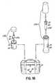
- a radiopharmaceutical assemblythat includes a radiopharmaceutical container (e.g., a syringe having a radiopharmaceutical disposed therein) and a radiopharmaceutical pig that is enclosable about the container to fully surround and support the container.
- this arrangementincludes a data tag that includes a data store and that is attached to the radiopharmaceutical container.
- An antenna systemis electrically connectable to the data tag upon the radiopharmaceutical container (and the data tag attached thereto) being placed in the radiopharmaceutical pig. This antenna system permits data to be read from and/or written to the data store of the data tag while the radiopharmaceutical pig is closed around the radiopharmaceutical container and the data tag.
- the radiopharmaceutical pigmay be characterized as having both a first pig component (e.g., a base) adapted to support the radiopharmaceutical container with the data tag and a second pig component (e.g., a cap) that is attachable to the first pig component and adapted to fully enclose the radiopharmaceutical container with the data tag within the radiopharmaceutical pig.
- the antenna systemmay be adapted to be electrically connectable to the data tag upon the radiopharmaceutical container being placed in the first pig component of the radiopharmaceutical pig.
- the antenna systempermits data to be read from and/or written to the data store of the data tag while the first pig component is attached to the second pig component and while the radiopharmaceutical container and the data tag are enclosed inside the radiopharmaceutical pig.
- the antenna systemmay include an antenna electrically connected to the data tag, an inner antenna adjacent an inner surface of one of the first pig component and the second pig component, an outer antenna adjacent an outer surface of one of the first pig component and the second pig component, and a conductive lead electrically connecting the inner antenna with the outer antenna.
- the antennamay be attached to (e.g., fixed to) the radiopharmaceutical container.
- the antenna systemmay be characterized as having an antenna locatable outside the radiopharmaceutical pig, and a conductive lead that has one end connected to the data tag within the radiopharmaceutical pig and an opposite end connected to the antenna located outside the radiopharmaceutical pig.
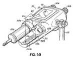
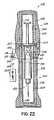
- a power injectorcapable of supporting a syringe that has a medical fluid disposed therein.
- the medical fluidis located between a plunger and a discharge tip of the syringe.
- the syringeincludes a data tag for storing data that is electromagnetically readable from the data tag.
- the injectorincludes a powerhead having a plunger drive adapted to interface with (e.g., be connected to) the plunger of the syringe.
- An injector control of the injectoris operatively connected to the powerhead.
- an electromagnetic device of the injectoris mounted on the powerhead and is in electrical communication with the injector control. This electromagnetic device includes a plurality of antennas operative to transmit electromagnetic signals to and receive electromagnetic signals from the data tag (e.g., to read data stored in the data tag).
- the electromagnetic devicemay include a plurality of tuning circuits electrically connected to respective antennas for tuning the respective antennas to a desired frequency(ies). For instance, in some embodiments, the tuning circuits may be utilized to tune the respective antennas to a frequency of about 13.56 Megahertz.
- a driver circuit of the electromagnetic devicemay be electrically connectable to the tuning circuits and the injector control. This driver circuit may function to provide drive signals to the tuning circuits causing the respective antennas to transmit electromagnetic signals to and receive electromagnetic signals from the data tag (e.g., to read data stored in the data tag).
- Some arrangementsmay include a switching circuit electrically connected between the driver circuit and the tuning circuits. This switching circuit may be utilized to connect the antennas in different circuit configurations. At least one of the switching circuit and the driver circuit are located in the powerhead of the injector.
- the powerheadmay include a forward end adapted to receive and support the syringe.
- This forward endmay include or be characterized as a mount of sorts adapted to accommodate.(e.g., receive and support) the syringe.
- the mountmay include a pressure jacket for supporting the syringe.
- the antennasmay be mounted on the pressure jacket.
- the mountmay not include a pressure jacket.
- the mountmay include what may be referred to as a cradle to support the syringe.
- the antennasmay be supported by and/or located within the cradle.
- Some arrangementsmay have a pressure jacket that includes an inner sleeve and an outer sleeve disposed about the inner sleeve.
- One or more antennasmay be located between the inner sleeve and the outer sleeve of the pressure jacket. For instance, a plurality of antennas may be disposed between the inner and outer sleeves and equally spaced about a circumference of the pressure jacket.
- One or more tuning circuitsmay be located between the inner sleeve and the outer sleeve.
- the injectormay include a heater (e.g., for heating the medical fluid disposed in the syringe).
- the heatermay be attached to or a component of a pressure jacket of the injector.
- the heatermay be attached to or a component of a cradle of the injector. In arrangements equipped with a heater, the heater may be electrically connected to the injector control.
- the syringemay exhibit any of a number of appropriate structural designs/configurations.
- the plunger of the syringeis substantially wholly contained within a barrel of the syringe.
- the syringemay exhibit any of a number of appropriate sizes (e.g., volume capacities).
- the syringeexhibits a volumetric capacity capable of accommodating a volume of fluid in excess of about 90 ml.
- the containerincludes a data tag operable to have data written thereto and read therefrom.
- a filling station of the systemmay be utilized to place the medical fluid in the container.
- This filling stationincludes an electromagnetic device operable to at least write data (e.g., relating to the fluid in the container) to the data tag.
- a disposal station of the systemmay be utilized in disposing of and/or preparing for disposal of the container (which may or may not still have medical fluid therein).
- This disposal stationalso includes an electromagnetic device operable to write data (e.g., relating to disposal of the container) to the data tag.
- the systemmay also include a hospital information system in electrical communications with one or more electromagnetic devices of the system.
- the systemmay include a warmer that may be utilized to heat the fluid in the container.
- This warmeris generally equipped with an electromagnetic device operable to write data (e.g., relating to placing the container in and/or removing the container from the warmer) to the data tag.
- the administration deviceis a power injector for use with a syringe.
- the power injectorgenerally includes both a control and an electromagnetic device that is electrically connected to the control and operable to write data (e.g., relating to administration of the medical fluid into the patient) to the data tag.
- the systemmay include a packaging station that may be used in placement of the container into a package.
- This packaging stationmay include an electromagnetic device operable to write data (e.g., relating to the package, the fluid and/or the container) to the data tag.
- the systemmay include a storage area for storing the container (which may or may not already have the medical fluid disposed therein).
- This storage areagenerally includes an electromagnetic device operable to write data (e.g., relating to placing the syringe in and/or removing the syringe from the storage area) to the data tag.
- the medical fluid that is in or is to be placed in the containeris a radiopharmaceutical.
- a packaging statione.g., radiopharmacy
- the packaging stationmay be utilized when placing the radiopharmaceutical pig in a package (e.g., a transport package).
- This packaging stationmay include an electromagnetic device operable to write data (e.g., relating to the radiopharmaceutical, the container, the pig, and/or the package) to the data tag.
- the systemmay include a calibration station that includes an electromagnetic device operable to write data (e.g., relating to radioactivity level of the radiopharmaceutical in the container) to the data tag.
- the systemmay include a treatment room where the radiopharmaceutical pig may be received and the container having the radiopharmaceutical disposed therein is removed for administration of the radiopharmaceutical to a patient.
- This treatment roommay include an electromagnetic device operable to write data (e.g., relating to administration of the radiopharmaceutical to the patient) to the data tag.
- a storage area of the systemmay include an electromagnetic device operable to write data (e.g., relating to placing the pig into and/or removing the pig from the storage area) to the data tag.
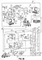
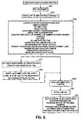
- a container life cycle 18arelates to medical fluid containers, for example, a syringe 20 suitable for storing contrast media.
- the syringes 20may be manufactured at a supplier facility 24 that is remote from a facility 42 in which a syringe 20 is to be used. Within the supplier facility 24, the syringe 20 is first filled with a contrast media at a filling station 28, and thereafter, labels 30 may be applied to respective syringes 20 at a labeling station 32. The syringes 20 may then be packaged either singularly or as a batch in an appropriate shipping carton 34 at a packaging station and the shipping cartons 34 may be temporarily queued or stored in a shipping/receiving department 38.
- Orders for the syringes 20can be received from various sources, for example, a purchasing office 25 within a health care facility 42, or a doctor's office 27 that may be part of, or independent from, the health care facility 42. Further, the orders may or may not be associated with a particular patient.
- the shipping cartons 34may enter a distribution channel 40 by which they may be delivered to various facilities 42, for example, hospitals, image service providers, and/or other health care facilities.
- the facility 42is a hospital that has a shipping/receiving area 44 for receiving the cartons 34 of prefilled syringes 20.
- prefilledherein describes a container that is designed to be sold and/or delivered to a user with at least some medical fluid already disposed in the container.
- the cartons 34are temporarily stored in a room 46 that may or may not be associated with a pharmacy within the hospital 42.
- the cartons 34may be transferred to a preparation room 48 at which the syringes 20 may be unpacked and placed in a warming oven 36 to raise the temperature of the contrast media up to about body temperature (e.g., between about 97°F and about 100°F).
- a warming oven 36to raise the temperature of the contrast media up to about body temperature (e.g., between about 97°F and about 100°F).
- one or more syringes 20may be removed from the warming oven 36, carried to the imaging suite 26a and loaded into a powered fluid injector 50.
- the injector 50operates to inject the contrast fluid into an examination subject or patient 52.
- the spent syringe 20may be processed for an authorized refilling or disposed of (e.g., in a disposal area 112) in a known manner.
- the term "prefilled syringe”means a syringe 20 prefilled with a medical fluid (e.g., contrast media) at a location remote from the preparation room 48 and imaging
- regulated and common practicesmay differ depending on the type of contrast media being used. Consequently, it is generally desirable to generate and provide a substantial amount of data relating to the handling of the syringe 20 throughout its life cycle, for example, at substantially every step from its filling to its disposal. Further, it is generally preferred that the data be transferable from one location, for example, the respective filling and labeling stations 28, 32, to another location, for example, the respective preparation and imaging rooms 48, 26a.
- RFIDradio frequency identification device
- a tag or transpondermay typically include an RF driver circuit and associated antenna.
- the RF driver circuitoften utilizes an integrated circuit chip having a programmable processor and associated memory, which are capable of storing the data and performing necessary demodulation and, if applicable, modulation functions.
- Data within a tagmay provide any manner of information relating to a prefilled syringe that is useful over the life of the syringe.
- an RFID systeminclude a means for reading data from, and in some applications, writing data to, the tags, as well as a means for communicating the data to a computer or information management system.
- an RFID systempreferably has the versatility to permit data to be written into, and read from, a tag at different times and at different locations.
- Wireless communicationis most often used to transfer data between a tag and a reader. Such communication is often based upon propagating electromagnetic waves, for example, radio frequency waves, by antenna structures present in both tags and readers. It is known to use either a common antenna or different antennas with an RFID tag to read data from, and write data to, the tag; closed loop, open loop, stripline, dipole and/or other antennas may be used. Further, RFID tags may be passive, that is, without an independent power supply, or active, that is, with a power supply such as a battery. In applications described herein, the choice of a particular antenna configuration and whether to use an active or passive RFID tag may or may not be application dependent.
- a syringe 20is filled with contrast media 22 at a filling station 28.
- a label 30 containing human readable and/or machine readable indiciais applied to the syringe 20 at the labeling station 32.
- an RFID tag 60is applied to the syringe 20.
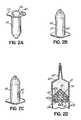
- the RFID tag 60incorporates an RFID chip and associated antenna in a known manner, for example, as shown in Fig. 5A by the RFID chip 212 and antenna 210; and the RFID tag 60 may be a part of or separate from the label 30. As shown in Figs.
- the RFID tagcan be applied at any suitable location on the syringe 20.
- the RFID tag 60can be applied to a rear surface 55 of a syringe flange 56; and as shown in Fig. 2B , the RFID tag 60 can be applied to an outer cylindrical surface 57 of the syringe.
- the RFID tag 60prior to the syringe 20 being loaded into a power head of an injector, the RFID tag 60 can be peeled off of the syringe 20 and applied to the injector. Upon removing the syringe 20 from the injector power head, the RFID tag may be reapplied to the syringe 20.
- the RFID tag 60can be applied to a rear surface 58 of a plunger 59.
- the plunger 59may have a core 61 covered by a molded material 63, and an RFID tag can be applied to or integrated into the plunger structure at various locations 65a, 65b, 65c, etc.
- an RFID tagmay be applied as shown at 60' on the discharge extension (e.g., nozzle) extending from the distal end of the syringe 20, or as shown at 60", an RFID tag can be applied to a front wall (e.g., tapering front wall) of the syringe 20.
- a read/write (“R/W”) device 62is connected to a labelling computer 64 and, at 506 ( Fig. 6 ), is operative to write data in the RFID tag 60 relating to contrast media or other pharmaceutical and its associated prefilled syringe or other container 20.
- Data that can be written to the RFID tag 60includes, but is not limited to, the following:
- the syringe 20is loaded into a shipping carton 34; and, at 510, the cartons 34 are stocked as inventory in a shipping/receiving department 38.
- the cartons 24may be further combined or palletized into a case or batch 67 for shipment to a customer; and a label 66 can be optionally applied to an individual shipping carton 34 or a unified case or batch 67 of cartons.
- the label 66can include human readable, machine readable indicia and/or be an RFID tag. Such indicia or RFID tag data may include but is not limited to an identification of the supplier and the product, the product expiration date and the packaging.
- the packaging codeidentifies whether the package is a single syringe, a carton of syringes or a case of syringes.
- an R/W device 68 connected to a shipping computer 70may be used to read data from, and write data to, the RFID tags 60 on the syringes 20 within the cartons 34.
- the R/W device 68may be used to read data from, and write data to, RFID tags associated with the labels 66.
- the shipping computer 70is able to identify parameters, for example, type of syringe, type of contrast media, contrast media concentration, etc., and confirm that those parameters meet the specifications of a particular order.
- the R/W device 68can be used to write into either the RFID tags 60 on the syringes 20, and/or the RFID tags on labels 66, data including, but not limited to, the following:
- the cartons 34then enter the distribution channel 40 and are received by a receiving department 44 of an imaging facility such as the hospital 42.
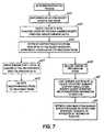
- An example of a syringe stocking and preparation processis illustrated in Fig. 7 .
- a R/W device 72 connected to a shipping/receiving computer 74reads, at 602, the syringe RFID tags 60 and/or the shipping carton RFID tags 66.
- the shipping/receiving computer 74stores the read data in an inventory database 76.
- the shipping/receiving computer 74is connected via a communications link, for example, an Ethernet LAN, etc., to a hospital administration computer 78 and other computers; and one or more versions of the inventory database 76 can be maintained in any of those computers.
- the receiving computer 76, or another computeris able to confirm that the delivered syringes conform to hospital purchase orders and, if applicable, automatically authorize payment of invoices therefor.
- the syringe RFID tags 60 within the cartons 34can, at 604, be updated with other data including, but not limited to:
- cartonsare delivered to a room 46.
- a R/W device 77 connected to a computer 79can be used to read the syringe RFID tags 60 and update a database within the computer 79.
- the computer 79via the communications link 80, can be used to update the inventory database 76 within administration computer 78, thereby confirming delivery of the syringes to the room 46 from the shipping/receiving area 44.
- the communications link 80may be implemented by an Ethernet, USB, RS-232, RS-422, or other interface that uses a standard PC-based communications protocol, for example, BLUETOOTH, parallel, IrDA, ZigBee, 802.11b/g, or other comparable wired or wireless connection.
- a standard PC-based communications protocolfor example, BLUETOOTH, parallel, IrDA, ZigBee, 802.11b/g, or other comparable wired or wireless connection.
- the R/W device 77is used to read the RFID tags, at 606, and find the cartons 34 containing the desired syringes. Further, reading the RFID tags permits an identification of the oldest inventory. (Since contrast media has a shelf life, it may be appropriate to follow a first-in/first-out inventory procedure.) Thereafter, at 608, an identified shipping carton 34 is delivered to the preparation room 48.
- the syringes 20are removed from a carton 34 and placed in the warmer 36 to bring the contrast media up to about body temperature.
- an R/W device 81is connected to a warmer control 82 having a user interface 86.
- the warmer control 82is electrically connected to an imaging information system 87 that, in turn, is connected to the communications link 80, and hence, to the other computers in the hospital 42.
- the R/W device 81Upon placing a syringe in the warmer 36, the R/W device 81 reads, at 610, a respective RFID tag 60 and transmits data with respect to the syringe 20 to a work-in-process database 84 in the imaging information system 87 as illustrated n Fig. 3A . Further, or alternatively, the imaging information system 87, via the communications link 80, can be used to update the inventory database 76, thereby allowing other computers to track information written to and read from the syringe RFID tags 60 in the warmer 36. R/W device 81 may also write to each RFID tag 60 the time and date each respective syringe 20 is placed in the warmer 36.
- the warmer control 82can, via the user interface 86, identify to the technologist a particular syringe inside the warmer 36, such as the syringe that has been in the warmer for the longest period of time. (Not only does contrast media have a limited shelf life, but the time spent in the warmer 36 should also be limited. Thus, inventory in the warmer 36 may also be handled on a first-in/first-out basis.)
- the R/W device 81Upon removing a syringe 20 from the warmer, at 612, the R/W device 81 writes the removal time and date to a respective RFID tag 60 and reads data identifying the syringe being removed.
- the work-in-process database 84 and other databasesare appropriately updated; and the warmer control 82 via the user interface 86 confirms to the technologist that the correct syringe has been removed.
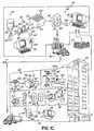
- one or more syringes 20a, 20bare then carried into an imaging suite 26a and loaded into respectively one or both of the mounts or faceplates 88a, 88b that are attachable on a powerhead 90 of a powered fluid injector 50 in a known manner.
- An exemplary injectoris shown and described in U.S. Patent Application No. 10/964,003 .
- the powerhead 90 discussed hereinis a dual head injector, single head injectors may be used as well.
- a suitable single-head injectoris shown in U.S. Patent No. 5,300,031 .
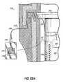
- a user-filled syringe having a volume of about 200 mlis mountable in a pressure jacket 250 of faceplate 88a.
- a prefilled syringe having a volume in excess of about 90 ml or moremay also be mountable in faceplate 88b.
- the injector powerhead 90includes hand-operated knobs 92a and 92b that are operative via an injector control circuit to control motors within respective plunger drives 95a, 95b.
- the plunger drives 95a, 95bare operable to move plungers within the respective syringes 20a, 20b in a known manner.
- Exemplary operations of a powerhead 90 and injector control 93are shown and described in U.S. Patent Application No. 10/964,002 . Additional exemplary operations are described in U.S. Patent Nos. 5,662,612 , 5,681,286 and 6,780,170 .
- the injector control 93is electrically connected to the hospital information system 78 via the communications link 80, and/or may be otherwise electrically connected to the imaging information system 87 by a communications link that uses a technology such as those noted above with reference to the communications link 80.
- the injector powerhead 90has a user interface 94, for example, a touch screen, for displaying current status and operating parameters of the injector 50.
- Powerhead 90is often mounted to a wheeled stand 100, which permits easy positioning of the powerhead 90 in the vicinity of the examination subject 52.
- the injector 50also has a remotely located console 96 with remote user interface 97, for example, a touch screen, a power supply 98 and other switches and components (not shown).
- the console 96may be used by an operator to enter programs and control the operation of the injector 50 from a remote location in a known manner. It will be appreciated that elements of the injector control 93 may be incorporated into the powerhead 90 or may be incorporated in other elements of the injector such as the power supply 98 or console 96, or may be distributed among these elements.
- the faceplate 88bhas an outward extending cradle 99 that supports a heater 106 mounted on a printed circuit ("PC") board 102.
- the heater 106is electrically connected to the injector control via a cable or connector and is operable by the injector control 93 to heat the syringe 20b in a known manner.
- the PC board 102further supports a R/W device 104b and an associated antenna system 229b.
- the R/W device 104bis also electrically connected to the injector control 93 and console 96. Further, the R/W device 104b may be activated by the injector control 93 to read data from an RFID tag 60b on a respective syringe 20b.
- Datamay be written to, and/or read from, the RFID tag 60b at any specified time when a syringe 20b is in proximity of a respective faceplate 88.
- the systemhas the ability to determine when syringes 20a, 20b are mounted in the respective faceplates 88a, 88b.
- the datamay be encrypted, and the data and data transfer may comply with 21 CFR 11, JCAHO, and HIPAA requirements.
- FIG. 8One example of a process for utilizing the syringe 20b within the imaging suite 26a is shown in Fig. 8 .
- This exampleis described principally with respect to the syringe 20b loaded in faceplate 88b; however the description is equally applicable to the syringe 20a loaded in faceplate 88a.
- the descriptionis further applicable to an injection process in which media is dispensed from both syringes 20a, 20b, either sequentially or simultaneously. Simultaneous dispensing from both syringes may be done at controlled and selected flow rates to achieve any desired concentration of the resulting mixture of media and/or media and saline in the two syringes.
- the R/W device 104bis activated to read data stored in the RFID tag 60b relating to contrast media or other pharmaceutical and its associated prefilled syringe or other container 20b.
- that informationincludes, but is not limited to:
- the R/W device 104balso writes the current time and date to the RFID device 60b to permit tracking of open-to-atmosphere time for the syringe 20b, which is also limited.
- the displacement of the syringe plungeris precisely controlled in accordance with data read from the RFID tag 60b relating to available syringe volume and/or dimensions thereof. Further, plunger feed is tracked, so that the contrast media remaining in the syringe can be continuously determined.
- the faceplates 88a, 88bhave a bidirectional communications link with the injector control 93, which may be used to transfer any of the above information between the syringes 20a, 20b and the injector control 93.
- the injector control 93may have syringe and drug information that may facilitate a procedure setup and result in reduced time and error.
- the injector control 93may read or write other information to and from the faceplates 88a, 88b, which is not directly pertinent to syringe information. Examples of this may include, but are not limited to:
- the mediais used in connection with a procedure.
- a technologistoperates a CT scanner control 101 that is effective to cause a CT scanner 103 to scan a patient 105 shown in phantom.
- the injector control 93may have one or more interfaces to a CAN communications bus 111, which is a known interface for the CT scanner control 101.
- the protocolis defined by the scanner manufacturers. Data and data transfer between the injector and scanner comply with 21 CFR 11, JCAHO, and HIPAA requirements.
- data transfer between the injector control 93 and CT scanner control 101may be bi-directional and may relate to the contrast media or other pharmaceutical and its associated prefilled syringe or other container 20b.
- dataincludes, but is not limited to, the following:
- the injector control 93Upon the injector control 93 determining that the desired volume of contrast media has been delivered, the injection process is stopped. At the end of the injection process, as shown in Fig. 8 at 708, the injector control 93 is operative to determine an exact volume of contrast media injected; and the injector control writes to the RFID tag 60b and/or updates the imaging information system 87 with data and information that includes, but is not limited to the following:
- the injector control 93has an interface providing a communications link 107 to a hard-copy printer 109.
- the printer 109may be, but is not limited to, a thermal, ink-jet, or laser based printer.
- the printer 109may be used to print pages and/or labels of various sizes and colors at specified times upon requests of a user, the CT scanner control 101, the hospital information system 78, or the injector control 93.
- the labelsmay be made part of patient records, requisition sheets, or other forms. Data output and data transfer may comply with 21 CFR 11, JCAHO, and HIPAA requirements/
- a label or pagemay be printed to provide information relating to the contrast media or other pharmaceutical, its associated prefilled syringe or other container 20b, and the use thereof.
- informationincludes, but is not limited to, the following:
- any of the above informationcan be exchanged between the injector control 93 and hospital information system 78.
- Potential uses for this capabilityinclude but are not limited to:
- the injector control 93can write to the RFID tag 60b to set a syringe-used flag that will help to prevent a reuse of the syringe 20b.
- the syringe 20bis then removed from the faceplate 88b; and if the procedure was aborted and the syringe was not used, it can be placed back into the warmer 36. In that process, information is read from, and written to, the RFID tag 60b as previously described. Further, the image information system 87 is also able to track the open-to-atmosphere time of the syringe and warn the technologists when an open-to-atmosphere time is exceeded.
- the syringe 20b removed from the faceplate 88bis empty, the syringe is typically transported to a disposal area 112 ( Figs. 1A , 3A and 4 ); and prior to disposal, another R/W device 114 connected to one of the other computers 75 reads the RFID tag 60b.
- the inventory database 76can thus track the identity of the syringe 20 being destroyed.
- the syringe disposal informationcan be communicated to a supplier computer 116 via a communications link 118 as seen in Fig. 3A , for example, via the Internet 83, a telephonic connection, or other comparable wired or wireless connection.
- Empty syringesinstead of being destroyed, may be returned to the supplier 24 for further processing, for example, disposal or refilling.
- the syringes 20pass through the hospital shipping/receiving area 44 and the RFID tags are again read to identify the syringes leaving the hospital; and the inventory database 76 is updated accordingly.
- the RFID tags 60bare again read to update a supplier inventory database 120 tracking syringes within the supplier's facilities.
- the RFID tags 60b on the syringes 20are updated or replaced depending on whether the syringe is destroyed or reconditioned and refilled by the supplier.
- the injector control 93facilitates information collection and transfer throughout a CT procedure.
- the RFID-enabled syringesprovide quicker and more accurate data recording, as well as an automated transfer of drug information.
- the printerallows for a hard copy of selected information to be incorporated into the patient or hospital record.
- the CT interfacevia CAN, facilitates information flow and collection at a single point, either the CT scanner system or the injector.
- the hospital information system interfaceimproves this information flow a step further, potentially creating an all-electronic system with minimal user intervention; this provides the opportunity for reduced error and efficiency in the CT scanning suite.
- the service mode functionis initiated by a field engineer using an intelligent identification (“ID") card 122.
- ID card 122has an RFID tag 124 that incorporates an RFID chip and associated antenna in a known manner.
- FIG. 9An exemplary process for using the ID card 122 for injector maintenance is shown in Fig. 9 .
- the RFID tag 124is loaded at the supplier facility 24 with data including, but not limited to, the following:
- the field engineerplaces the ID card 122 on an empty faceplate 88b, thereby allowing the R/W device 104b to read and write to the RFID tag 124.
- a field engineer identification and service time and dateare stored in the injector control 93.
- the injector user interfaces 94, 97are effective to switch the injector 50 into a service mode, thereby disabling several operational checks and features that are used in a normal injection cycle but which inhibit operating the injector 50 for service purposes.
- the R/W device 104continues to periodically read the identification and security codes from the RFID tag 124.
- the injector control 93Upon failure to successfully read the RFID tag 124, for example, because the ID card 122 has been removed from the faceplate 88b, the injector control 93 automatically switches the injector 50 out of the service mode. Thus, the previously disabled operational checks and features are re-enabled, and the injector is ready to operate in a normal injection cycle. Further, at 804, the injector control 93 is operative to read from the RFID tag 124 information and data relating to factory updates to the injector components and software.
- the field engineerinitiates uploads of software upgrades from the RFID tag 124 to the injector control 93.
- mechanical componentsare serviced, mechanical upgrades are installed and their operation is verified.
- the injector control 93writes to the RFID tag 124 on the ID card 122 data including, but not limited to, the following:
- the RFID tag 124Upon the field engineer returning to the supplier facility 24, the RFID tag 124 is read; and the service information is stored in a history file associated with the particular injector that was serviced.
- RF communications systembetween an RFID tag 60 on a container 20 and a power injector control 93 provides for further exemplary embodiments of the RF communications system.
- Known RFID systemsuse electromagnetic (EM) fields to communicate between an R/W device that includes a tuned antenna and one or more RFID tags or transponders.
- the R/W devicemay send out data using EM fields at a specific frequency; and with passive RFID tags, this EM energy powers the tag, which in turn enables processing of this received data.
- the RFID tagmay transmit data that is received and processed by the R/W device.
- EMelectromagnetic
- An RFIDis difficult to implement around metallic or diamagnetic materials, for example, water, saline or a medical fluid in a container such as a contrast media in a syringe. These materials absorb and/or reflect RF energy, making successful read-write RFID operations difficult, especially with the low power regulations for RF frequencies.
- the angle between a plane of the RFID tag antenna and a plane of the R/W device antennais critical. For optimum performance, the plane of the RFID tag antenna should be substantially parallel to the plane of the R/W device antenna. As shown in Fig.
- orientation of the syringe 20bplaces the RFID tag antenna 210 relatively close to the R/W device 104b; and therefore, coupling RF signals therebetween to facilitate reading data from, and/or writing data to, the RFID tag 60b.
- contrast media in the syringe 20bis between the RFID tag antenna 210 and the R/W device 104b. The contrast media attenuates the RF field strength from the antenna of the R/W device 104b and interferes with its RF coupling with the RFID tag antenna 210.
- a syringe 20b having a label 30b with an antenna 210 and RF driver 212is positioned above faceplate 88b, ready to be loaded therein.
- a first PC board 102 and a second PC board 103are mounted in faceplate 88b, so as to be nonparallel.
- the PC boards 102, 103form sides of a V-shape and thus, form an angle of less than 180 degrees therebetween.
- PC board 102supports a first antenna loop 220 and its associated tuning circuit 226, and PC board 103 supports a second antenna loop 222 and its associated tuning circuit 228.
- the first and second antenna loops 220, 222 and respective tuning circuits 226, 228are connected to an R/W RF driver circuit 224b through a switching circuit 241 b to collectively form the electromagnetic R/W device 104b.
- the R/W RF driver circuit 224b and switching circuit 241bmay be mounted on a separate PC board 102b (shown in phantom), which is located beneath, and electrically connected to, the PC board 102.
- the R/W RF driver circuit 224b and/or the switching circuit 241 bmay be mounted in the power head 90 in association with the injector control 93.
- an antenna system 229bcomprising the antenna loops 220, 222, respective tuning circuits 226, 228 and switching circuit 241 b is connectable in different electrical configurations to achieve an optimum RF coupling between the R/W device 104b and the RFID tag 60b.
- power from the R/W RF driver circuit 224bis applied to the input 230 of a tuning circuit 226 that is connected to a signal lead 231 of the primary antenna loop 220 on PC board 102. Further, input 234 of the tuning circuit 228, which is connected to a signal lead 235 of the secondary antenna loop 222 on PC board 103, is left open or floating.
- a primary antenna loop ground lead 232is connected to ground with the secondary antenna loop ground lead 236.
- the powered primary antenna loop 220 on PC board 102is tuned to a frequency indicated by a protocol of the RFID tag 60b, for example, about 13.56 Megahertz, which permits propagation of the RF signal into the surrounding area.
- An RF signal from the primary antenna loop 220is coupled with the secondary antenna loop 222 on PC board 103, because the secondary antenna loop 222 is also tuned to resonate at about 13.56 Megahertz.
- the angled, V-shape orientation of the PC boards 102, 103 and respective areas of antenna loops 220, 222provide an expanded or increased total antenna area for the R/W device 104b.
- an effective antenna areaextends circumferentially around a substantially greater area of a syringe 20b than is possible with the single PC board 102 shown in Fig. 5A .
- the antenna power provided by the RF driver circuit 224bis also spread over a larger area represented by the combined areas of antenna loops 220, 222.
- the larger antenna area shown in Fig. 13Aimproves the RF coupling with the antenna 210 of the RFID tag 60b.
- antenna loop 222 on PC board 103can be made the primary loop by disconnecting or opening an input 230 of the tuning circuit 226 and connecting the tuning circuit input 234 of the antenna loop 222 to the power output of the R/W RF driver circuit 224b.
- First antenna loop ground lead 232 and second antenna loop ground lead 236continue to be connected to ground.
- both antenna loops 220, 222are tuned to resonate at the RFID tag frequency, that is, about 13.56 Megahertz.
- the antenna configuration of Fig. 13Bmay provide better RF coupling with the antenna 210 of the RFID tag 60b depending on the orientation of the syringe 20b and thus, the circumferential location of the RFID tag 60b.
- FIG. 13CAnother configuration of the antenna loops 220, 222 is shown in Fig. 13C wherein the tuning circuit input 230 of the first antenna loop 220 is connected to the power output of the R/W RF driver circuit 224b; and first antenna loop ground lead 232 is connected to ground.
- the tuning circuit input 234 and ground lead 236 of antenna loop 222are connected to ground, which prevents the second antenna loop 222 from resonating at the RFID tag frequency, which, in this application, is 13.56 MHz.
- the tuning circuit input 234 of the second antenna loop 222 on PC board 103is connected to the power output of the R/W RF driver circuit 224b; and tuning circuit input 230 of the first antenna loop 220 is connected to ground along with antenna loop ground leads 232 and 236.
- the first antenna loop 220does not resonate at the RFID tag frequency of 13.56 MHz; and only the second antenna loop 222 is tuned to resonate at that frequency.
- this antenna configurationprovides the best RF coupling with the antenna 210 of the RFID tag 60b.
- a usermay be instructed to load the syringe 20b in the faceplate 88b so that the label 30b is always in the same orientation.
- the RFID tag 60bmay be removable from the syringe and mountable at a fixed location on the injector 50.
- an R/W antennacan be designed and placed in a fixed location to have optimum RF coupling with an RFID tag.
- a usermay have no limitations on where the RFID tag 60b is located on the syringe 20b or how the RFID tag 60b is oriented when the syringe 20b is mounted on a faceplate 88b.
- the RFID tag 60bmay have any circumferential location around a barrel of the syringe 20b or within the faceplate 88b. Further, in such applications, it is difficult to precisely predict which of the antenna configurations in Figs. 13A-13D will provide the best RF coupling with an RFID tag having an unknown orientation with respect to R/W device 104b. This is due, in part, to the complex and somewhat unpredictable EM fields formed around materials that reflect and/or absorb such fields. Therefore, all of the antenna configurations of Figs. 13A-13B may be utilized.
- switches 238, 240 on PC board 102comprise the switching circuit 241 b, which is used to selectively connect respective tuning circuit inputs 230, 234 to either a power output or terminal 242 from R/W RF driver circuit 224b, a ground terminal 244 or an open state represented by contacts 246.
- the ground leads 232, 236 of respective antenna loops 220, 222are always connected to the ground 244.
- the contacts of switches 238, 240have notations to Figs. 13A-13D indicating the switch states corresponding to the antenna configurations of Figs. 13A-13D .
- a communications cycleis initiated either automatically by the injector control 93 detecting a syringe 20b being loaded into the faceplate 88b (such as by the movement of a mounting arm of the faceplate 88b, causing a magnet in the mounting arm to move into confronting relationship with a magnetic sensor in the injector), or manually by an operator providing an input to the injector control 93.
- the injector controlat 900, operates the switches 238, 240 to connect the antenna loops 220, 222 in a first of the four circuit configurations, for example, the circuit configuration shown in Fig. 13A .
- the injector control 93initiates, at 902, a communications protocol between the R/W RF driver circuit 224b and the RF driver circuit 212 of the RFID tag 60b.
- Initiating a communications protocolis a known process by which the R/W RF driver circuit 224b causes the R/W antenna system 229b to emit an electromagnetic signal in order to establish a reliable RF coupling with the tag antenna 210 and thus, establish an RF communications with the RFID tag 60b.
- the R/W device 104bcan read data from and/or write data to the RFID tag 60b.
- the injector control 93determines that the communications protocol and hence, the RF communications link, has been established, the injector control 93 commands, at 906, the R/W drive 104b to proceed with the reading of data from, and/or the writing of data to, the RFID tag 60b. However, if, at 904, the injector control 93 determines that the communications protocol failed, and a successful RF communications between the R/W device 104b and the RFID tag 60b is not made, the injector control 93 determines, at 908, whether all antenna loop configurations have been tried. If not, the injector control 93 operates, at 910, the switches 238, 240 to connect the antenna loops 220, 222 into another one of the four circuit configurations shown in Figs.
- the injector control 93automatically iterates through the process steps 902-908 to reconnect the antenna loops 220-222 in different circuit configurations in an attempt to establish a successful RF communications protocol or link. If, at 908, the injector control 93 has tried all of the antenna loop configurations without success, it sets, at 912, a protocol failure flag or error message.
- Figs. 11-14illustrate different antenna systems 229b that may be employed with an electromagnetic R/W device 104b to read a data tag 60b applied to a syringe 20b mounted in an open faceplate 88b.
- a syringe 20athat often is a user-filled disposable syringe, is mounted within a translucent or transparent pressure jacket 250 of faceplate 88a.
- the syringe 20ais secured in the pressure jacket 250 by a cap 252 in a known manner.
- a data tag 60ais integrated into a label 30a applied to the syringe 20a, and the structure and operation of data tag 60a is substantially identical to the data tag 60b previously described.
- the pressure jacket 250may be equipped with an antenna system 229a, which includes of an array of antenna loops 254, 256, 258 spaced about a circumference of the syringe 20a. While equal spacing of the antenna loops is shown, other spacing may be used.
- the pressure jacket 250has inner and outer cylindrical sleeves 260, 262, respectively. As illustrated, the antenna loops 254, 256, 258 may be molded between the inner and outer sleeves 260, 262. Referring to Fig.
- the antenna loops 254, 256, 258have respective tuning circuits 264, 266, 268, which may be molded between the inner and outer cylindrical sleeves 260, 262.
- Tuning circuit input leads 270, 272, 274 and a ground lead 276may be bundled into a cable 278 that extends from the face plate 88a to a switching circuit 241 a located in the power head 90.
- the switching circuit 241 amay operate in any appropriate manner, such as in a manner like that previously described with respect to the switching circuit 241 b of Fig. 14 .
- the switching circuit 241 amay be controlled by an R/W driver circuit 224a that may be located in the power head 90.
- the R/W driver circuit 224amay execute a communications cycle utilizing the antenna loops 254, 256, 258 in a manner similar to that described with respect to Fig. 15 .
- the R/W RF driver circuit 224amay connect the antenna loops 254, 256, 258 in different circuit configurations in order to find a circuit configuration providing the most reliable communications with the data tag 60a.
- the antenna system 229ais shown as including three antenna loops, other systems may include other appropriate quantities and/or arrangements of antenna loops.
- the antenna system 229ais shown as a component of the pressure jacket 250, other embodiments may include an antenna system having a plurality of antenna loops that is not associated with a pressure jacket.
- the antenna systems 229a, 229bmay advantageously incorporate one or more antenna loops that can be powered individually, or mutually coupled together, to produce several tuned antenna and EM field configurations.
- the antenna systems 229a, 229bmay be characterized as providing an effective low power system for reading data from and/or writing data to a data tag that may be disposed at any location on a contrast media syringe.
- that contrast media syringemay exhibit virtually any orientation relative to a faceplate of a power injector 50 with which it may be associated.
- the antenna systems 229a, 229bmay positively address various challenges relating to use of an RF communications system around metallic or diamagnetic materials, e.g., water, saline, contrast media, or other fluids, and/or in a regulated environment that may mandate use of a relatively low power RF signal.
- metallic or diamagnetic materialse.g., water, saline, contrast media, or other fluids
- a container life cycle 18bmay relate to other types of containers 20c that are used to store radiopharmaceuticals. While much of the container life cycle 18b of Fig. 1B is generally similar to container life cycle 18a of Fig. 1A , radiopharmaceuticals require different handling and storage.
- the container 20cis schematically shown as a syringe, but the container 20c may be a vial or other container suitable for use with a radiopharmaceutical.
- a quality control check of the radiopharmaceuticalmay be performed at quality control station 31. Thereafter, the container 20c is placed or loaded into a pig 33, which generally includes lead and/or other radiation shielding material to protect handlers from exposure to radiation from the radiopharmaceutical.
- the loaded pig 33may then be packaged either singularly or as a batch in an appropriate shipping carton 34 and shipped to a customer or user.
- the cartons 34are stored in a nuclear medicine department 29 within the hospital 42, which generally includes a radiopharmacy 48 and treatment room 26b.
- a radiopharmaceutical containermay be removed from a pig and placed in a calibration tool 49 to calibrate an activity level of the radiopharmaceutical to a desired level prior to its use.
- the radiopharmaceutical containermay then be placed back into the pig; and at an appropriate time, the pig may be carried to a treatment room 26b.
- the radiopharmaceutical containermay again be removed from the pig, and the radiopharmaceutical may be injected into a patient 52 either manually or using a powered injector such as that shown and described herein.
- the radiopharmaceutical containermay be placed in the pig and returned to the supplier facility 24; and at a post processing station 51, the radiopharmaceutical container may be disposed of and the pig may be cleaned for reuse.
- FIG. 6An exemplary radiopharmaceutical container draw-up and packaging process implemented at a supplier facility 24 is illustrated in Fig. 6 .
- a radiopharmaceutical container 20cis filled, at 502, with a radiopharmaceutical at a draw-up station 28. Thereafter, at 504, a label 30 and/or RFID tag 60 are applied to the radiopharmaceutical container 20c at the labeling station 32.
- the RFID tag 60can be integrated with, or separate from, the label, and the RFID tag 60 incorporates an RFID chip and associated antenna in a known manner.
- the RFID tag 60can be applied at any suitable location on a radiopharmaceutical container.
- the RFID tag 60can be part of a label 30 that is applied to a radiopharmaceutical syringe 20d or a radiopharmaceutical vial 20e.
- an RFID tagcan be applied to, or integrated into, the syringe structure at different locations as previously described with respect to Figs. 2A-2D .
- the syringe label 30may be removable; and immediately prior to the syringe 20d being loaded into a power injector, a portion of the label 30 including the RFID tag can be peeled off and applied to the injector or an associated reader. Upon removing the radiopharmaceutical syringe 20d from the injector, the RFID tag 30 is reapplied to the radiopharmaceutical container 20d.
- An identical or different label 30can also or alternatively be applied to a radiopharmaceutical syringe pig 33a or a radiopharmaceutical vial pig 33b.
- a label 30 with an RFID tag 60can be applied to a carton 34, for example, a satchel, designed to transport a plurality of pigs.
- a read/write (“R/W”) device 62is connected to a label computer 64 and, at 506 ( Fig. 6 ), is operative to read data from and/or write data to the RFID tag 60 for a particular radiopharmaceutical container 20c.
- the draw-up station 28may include a draw-up station computer 41 in electrical communications with an R/W device 43; and depending on the application, either or both of the R/W devices 43, 62 can be used to write data to the RFID tag 60, which data includes but is not limited to the data previously described with respect to step 506.
- the datamay also include all of the dose and prescription information that is currently being printed on a prescription label and/or encoded into a bar code, measured radioactivity levels, for example, Tc-99 and Mo-99, and time when measured, an identity of radioactive elements used, for example, Tc-99 and Mo-99, their respective sources, and other suitable data.
- quality control checksmay be performed (e.g., at a quality control station 31) to determine, for example, a purity of the radiopharmaceutical, the correctness of information on the label, dosage information, etc.
- the quality control station 31may include a quality control computer 45 and an associated R/W device 47 that may be used to read data from and/or write data to the RFID tag 60 depending on the quality control checks performed and/or other system specifications.
- the container 20cmay then, at 509, be inserted into a pig 33 for handling, storage and transportation.
- a label 65can optionally be applied to the pig 33.
- the label 65can include human readable indicia, machine readable indicia and/or an RFID tag as described with respect to the label 30.
- either the R/W device 62 or another R/W devicecan be used to read data from and/or write data to the RFID tag 65.
- Data that can be written to the RFID tag 65may include data written to the RFID tag 60 on the container 20c as well as data that includes, but is not limited to, the following:
- one or more pigs 33may be loaded into a shipping carton 34 (see Fig. 1 B) .
- the cartons 34may be stocked as inventory in a shipping/receiving department 38.
- the cartons 24may be further combined or palletized into a case or batch 67 for shipment to a customer; and a label 66 can be optionally applied to an individual shipping carton 34 or a unified case or batch 67 of cartons.
- the cartons 34may then enter the distribution channel 40 and may be received by a receiving department 44 of a treatment facility such as the hospital 42.
- a stocking and preparation processmay be executed in process steps 602 and 604, which are similar to those previous described.
- cartonsmay be delivered to a hospital radiopharmacy 48 (or nuclear medicine department of a healthcare facility or other appropriate location), and within the radiopharmacy 48, an R/W device 77 connected to a computer 79 can be used to read data from and/or write data to the pig RFID tags 65.
- the computer 79via the communications link 80, can also be used to update the medicine tracking database 76 within the hospital administration computer 78.
- a calibration tool 49is often used, at 607, to check or validate a radioactivity level of the dosage of the radiopharmaceutical within a container.
- This check/validationcan be performed using any appropriate process and/or calibration tool.
- the calibration tool 49may have a calibration computer 85 connected to an R/W device 89 that, during the check/validation process, can be used to read data from and/or write check/validation data to the container RFID tags 30 and/or the pig RFID tags 65.
- This check/validation datamay include but is not limited to
- a pig 33may be delivered to a treatment room for use.
- the radiopharmaceuticalcan be administered manually or using a power injector.
- a syringe 20d or vial 20e containing the radiopharmaceuticalis removed from a respective pig 33 for manual administration; but in other applications, a power injector and process as previously shown and described with respect to Fig. 8 may be used.
- the R/W device 104 associated with the injector control 93see Fig.
- 3Bmay write the current time and date to the RFID tag 60 to permit tracking of out-of-pig time (e.g., the duration of time that a syringe or vial is not housed within the pig), if desired.
- out-of-pig timee.g., the duration of time that a syringe or vial is not housed within the pig
- the displacement of the radiopharmaceutical container plungermay be precisely controlled, and plunger feed may be tracked (e.g., recorded and written to a tag associated with syringe and/or pig).
- the R/W device 104 of Fig. 3Bcan read a radioactivity level and time and date of measurement written into the RFID tag by the quality control station 31 ( Fig. 1 B) .
- Injector control 93can then calculate the time elapsed between the measured radioactivity level and the scheduled treatment time and date.
- the injector control 93can further calculate the decay in radioactivity level over the elapsed time; and then, being programmed with the prescribed radiopharmaceutical dose, the injector control can calculate the correct unit dose volume to be injected.
- a calibration tool 49may not be required. If the radiopharmaceutical is to be injected manually, the computer 79 and associated R/W device 77 can be used by a clinician or other appropriate personnel in a similar fashion to provide a display of the computed current unit dosage without using a calibration tool.
- the radiopharmaceutical container 20cmay be removed from the faceplate 88b and placed back into a respective pig 33 as indicated at 802 in Fig. 19 .
- the pig 33may then be placed in the same or a different carton and, at 804, returned to the shipping department 44 and, at 806, returned to the supplier facility 24.
- the label associated with the radiopharmaceutical containermay be read just prior to disposal to assist in determining how long the container will have to be stored in a radiation-shielding disposal and/or storage container before substantially all of its radioactivity has decayed.
- the initial radioactivity of the radiopharmaceuticalmay be written to the tag at the time of filling the container. Subsequent to that initial fill time, the radioactivity of that radiopharmaceutical decays. Since the rate of decay is generally known, one may utilize the rate of decay and the duration of time that has passed from the initial fill time to determine how much storage time may be needed to sufficiently ensure that the spent container no longer has a significant amount of radioactivity associated therewith. This calculation of storage time may be accomplished manually and/or electronically (e.g., using an appropriate computer interconnected with the reader utilized to read the tag just prior to disposal).
- the used radiopharmaceutical containermay undergo suitable processing for disposal and, at 810, the associated pig may be cleaned for reuse.
- any of the computers previously describedcan be used to read data from and/or write data to the RFID tags on the container 20c, pig 33, carton 34 and/or pallet 67. Such activity may be application dependent to fulfill the needs of a particular supplier, customer, doctor and/or hospital.
- a post processing computer 53may be connected to an R/W device 55 that can be used to read data from and/or write data to the RFID tags 60 on one or both the radiopharmaceutical container or the pig.
- the post processing computer 53may be able (via a communications link 57) to update a supplier inventory database 120 tracking radiopharmaceutical containers and pigs within the supplier's facilities.
- the RFID tags 60 on the radiopharmaceutical pigs 33may be updated or replaced.
- data relating to the radiopharmaceutical containers and pigscan be communicated from a supplier computer 116 to computer 79 within the hospital 42 via a communications link 118, for example, an Internet connection, a telephonic connection or other suitable link.
- RF tags 60may be applied to a radioactive pharmaceutical container 20c that is subsequently placed in a lead lined pig 33.
- the piglimits the usability of the RF tags 60 and may prevent use thereof unless the container 20c is removed from the pig 33. Therefore, it would be highly desirable to be able to read data from, and write data to, the RF tag 60 on the radiopharmaceutical container 20c when it is stored inside the pig 33.
- Suchis achieved by an exemplary embodiment of a pig-mounted antenna system shown in Figs. 20-22 .
- a radiopharmaceutical pig 33bhas an elongated base 322 and an elongated cap 324.
- the base 322 and cap 324can be formed in any of a wide variety of shapes and sizes, however, a substantially cylindrical shape is illustrated.
- the cap 324is joined to the base 322 by a threaded interconnection 325 in a known manner.
- a cap shielding element 326 within the cap 324 and a base shielding element 328 within the base 322are used to block radiation that may be emitted from the radiopharmaceutical within a syringe 20c.
- the shielding elements 326, 328can be formed from any material that is effective to block radiation, for example, lead, tungsten, a filled polymer composite material, etc.
- the cap shielding element 326forms a protrusion 329 that overlaps the base shielding element 328 when the cap 324 is mounted on the base 322. This overlap of the shields 326, 328 facilitates a blockage of radiation through a discontinuity in the shields caused by the cap 324 being separable from the base 322.
- the cap 324further has a cap shell 330 comprised of an outer shell portion 332 and an inner shell portion 334.
- the base 322has a cap shell 336 comprised of an outer shell portion 338 and an inner shell portion 340.
- the base and cap shells 328, 330are made from a plastic material, for example, a polycarbonate resin, etc.
- a label 30is affixed to the radiopharmaceutical syringe 22c by known means, for example, an adhesive, tape, elastic bands, etc. Indeed, the label 30 may be affixed to the radiopharmaceutical syringe 20c in any appropriate manner (e.g., so that it is not easily removable).
- the label 30contains indicia 346 that is in human readable and/or machine readable form.
- the label 30further has an RFID tag 60 that comprises an RFID integrated circuit chip 212 and at least one radio frequency antenna 210.
- the radiopharmaceutical syringe 20cis often manufactured at a facility independent of the healthcare facility where it is to be used.
- data relating to the radiopharmaceutical syringe 20cis often collected at the point of its manufacture. Further, additional data is often collected at different points in a distribution channel at which the radiopharmaceutical pig 33b containing the radiopharmaceutical syringe 20c is handled. Data is also collected upon the radiopharmaceutical syringe 20c being used and thereafter, upon its disposal or cleaning for an authorized reuse. Thus, over the life of the radiopharmaceutical syringe 20c and associated radiopharmaceutical pig 33b, data that can be written into the RF ID tag 60 at different times in the life cycle of the syringe 20c has been previously described.
- Such dataincludes but is not limited to the decay factor for a radiopharmaceutical (e.g., half life of pharmaceutical), its prescribed activity level (curie level of radiation) at injection time, the activity level at another time (such as filling time), and/or the time at which the preparing physician or radiopharmacist assumed the radiopharmaceutical would be injected.
- the activity levelis a function of time due to the short half life of most radiopharmaceuticals, so the activity level is designed for a specific injection time.
- At least one radio frequency inner antenna 358is applied over an inner surface of the inner base shell 340; and at least one radio frequency outer antenna 364 is applied over an outer surface of the outer base shell 338.
- a hole 360extends through the inner base shell 340, the base shield 328, and the outer base shell 338.
- At least one connecting lead 362, for example, a copper wire lead,extends through the hole 360 and has one end connected to the inner antenna 358 and an opposite end connected to the outer antenna 364.
- the inner antenna 358is designed to couple with the RFID antenna 210 connected to the RFID chip 212.
- the outer antenna 364is designed to electromagnetically couple with a read/write ("R/W") device 366 in the same way that the RFID antenna 210 would couple with the R/W device 366.
- the R/W device 366is connected to a computer 368 in a known manner.
- the R/W device 366electromagnetically couples with the RFID antenna 210 via the inner and outer antennas 358, 364 respectively.
- the R/W device 366can be used to read information from, and/or write information to, the RFID chip 212 of the RFID tag 60 on the radiopharmaceutical syringe 20c via an RFID antenna system comprising the antennas 210, 358, 362, 364.
- the antennamay simply comprise leads of a sufficient length to be used as an RFID antenna, in which case there may not be a coiled antenna section 364.
- FIG. 21Another exemplary radiopharmaceutical pig 33b and radiopharmaceutical syringe 20c utilizing the RFID tag 60 is shown in Fig. 21 .
- Inner and outer antennas 358, 364are located on respective inner and outer surfaces 370, 372 of a top of the cap 324.
- the antennas 358, 364are electrically connected by at least one lead 362 extending through a hole 374 in the top of the cap 324.
- the R/W device 366is able to electromagnetically couple with the RFID antenna 210 via the inner and outer antennas 358, 364 respectively.
- the R/W device 366can be used to read information from, and/or write information to, the RFID chip 212 of the RFID tag 60 on the radiopharmaceutical syringe 20c via an RFID antenna system comprising the antennas 210, 358, 364.
- the top of the cap 324often experiences less radiation exposure than the base shell 336. Further, the cap outer surface 372 often experiences less physical contact than the base outer shell 338 during the handling of the radiopharmaceutical pig 33b; and hence, the outer antenna 362 on the cap outer surface 372 is less subject to physical damage.
- FIG. 22 and 22AA further radiopharmaceutical pig 33b and radiopharmaceutical syringe 20c utilizing an RFID tag 60 is shown in Figs. 22 and 22A .
- the RFID tag 60has an RFID chip 212 on a first portion of a label 30c that is attached to the radiopharmaceutical syringe 20c in a manner described earlier with respect to Fig. 20 .
- a second portion of the label 30dis located outside of the radiopharmaceutical pig 33b and has at least one RFID antenna 210 thereon.
- the RFID chip 212 on the first label portion 30cis electrically connected to the antenna 210 by at least one electrically conductive lead 376 integral with a tether 378.
- the conductive lead 376 and tether 378may be formed from any materials that provide the desired electrical and mechanical properties, for example, an insulated or uninsulated copper wire, a copper trace laminated on a substrate, etc.
- the threaded connector 325is designed to provide a clearance for the conductive lead 376 and tether 378, so that the cap 324 can be attached and removed from the base 322 without damaging the conductive lead 376 and tether 378.
- the R/W device 366is able to electromagnetically couple with the RFID antenna 210, and the RFID antenna 210 communicates data to and from the RFID chip 212 via the conductive lead 376.
- the R/W device 366can be used to read information from, and/or write information to, the RFID chip 212 of the RFID tag 60 on the radiopharmaceutical syringe 20c via an RFID antenna system comprising the antenna 210 and conductive lead 376.
- a label 30 having an RFID chip 212 and associated antenna 210is applied to the radiopharmaceutical syringe 20c, and the radiopharmaceutical syringe 20c can be placed in a radiopharmaceutical pig 33b.
- dataincluding but not limited to the identity of the syringe and pig can be written to the RFID tag 60 in a manner previously described with respect to Figs. 1A and 1B .
- the radiopharmaceutical syringe 20c and pig 33bare then transported to a location where the syringe 20c is filled with a desired radiopharmaceutical.
- This locationmay be at a radiopharmaceutical supplier or a location of a user of the radiopharmaceutical syringe 20c.
- datacan be entered into the RFID tag 60 relating to the filling process, the radiopharmaceutical being filled, and the how the radiopharmaceutical is to be used.
- the pig 33b holding the syringe 20c filled with the radiopharmaceuticalmay be transported and stored several times before it is delivered for use in a preparation and/or imaging room. During use, the syringe 20c is removed from the pig 33b, and the radiopharmaceutical is injected into an examination subject or patient.
- the empty syringe 20cis placed back in the pig 33b and returned to the pharmaceutical supplier or other location for proper disposal of the radiopharmaceutical syringe 20c and reconditioning of the radiopharmaceutical pig 33b for reuse.
- an R/W device 366can be used to read data from, and/or write data to, the RFID tag 60, thereby providing complete chronological history of the radiopharmaceutical pig 33b and syringe radiopharmaceutical 20c over the respective life cycles.
- the systems illustrated in Figs. 1A , 3A , 1B , 3Bhave an advantage in that almost any information is able to be transferred between all entities involved in a life cycle of a syringe 20, which is any entity that can communicate with the communication link 80. Therefore, data available from a website on the internet 83 can be utilized during the life cycle of the syringe 20.
- Such internet communications capabilitiespermits remote service of a power injector 50, downloading of an injection protocol, communication with a remotely located physician, media supplier or other entity of interest and other functions.
- an RFID chip 212may be positioned inside the pig.
- the chip 212may also be located outside the pig along with an associated antenna, and the chip may be physically attached to the syringe 20c by a string or other attachment so that the radiopharmaceutical syringe 20c and RFID information therein remain associated.
- the pig 33bmay carry an RFID tag and antenna with no mechanical attachment to the syringe, but it may simply be known that the data therein relates to the syringe that is in the pig.
- the antenna systems 229a, 229buse one, two and three antenna loops; however, any number of antenna loops may be used.
- the antenna loopsmay be configured in any shape and be in the same plane or in different planes. Further, the antenna loops may or may not be overlapping. In may, however, be preferable that the antenna loops be individually tuned to resonate at a specific frequency used by the RFID protocol.
- a switching circuit 241 bis located on the same PC board 102 as an RF driver circuit 224b; however, a switching circuit may be located on the second PC board 103, be split between the two PC boards 102, 103 or located elsewhere, for example, with the power injector as shown in Fig. 17 .
- the R/W antenna systems 229a, 229bare applied to a pharmaceutical injection assembly; however, the R/W antenna systems 229a, 229b utilizing multiple nonparallel antennas may be applied to any devices that support a medical fluid container.
- Such devicesinclude but are not limited to a warmer oven or warming box, a container filling station, a pig or other nuclear medicine container, a dose calibration station, a handheld powered medical fluid dispenser, a syringe disposal station, or other device.
- the containermay be an IV bag 130 filled with a medical fluid.
- Tubing 132 from the IV bag 130may interface with an infusion pump 134 so that a flow of medical fluid from the IV bag 130 may be regulated via use of the pump 134.
- one end of the tubing 132is generally associated with the IV bag 130, the other end of the tubing 132 may be connected to a patient in a known manner.
- the IV bag 130may have a label 30 with a data tag 60 as previously described herein, for example, an RFID tag.
- the infusion pump 134may be in electrical communication with an electromagnetic device capable of reading data from and/or writing data to the data tag 60 of the IV bag 130.
- the electromagnetic devicemay be attached to and/or located within the infusion pump 134.
- the infusion pump 134may have a control 136 connected to the communications link 80 in a manner similar to that described with respect to the injector control 93 shown in Figs. 1A and 1B .
- the systems of Figs. 1C and 3Cmay permit activity relating to the IV bag 130, the medical fluid therein, and/or the infusion pump 134 to be tracked and recorded (e.g., over a life cycle of the IV bag 130).
- a heater 106is mounted on the PC boards 102, 103; however, the heater 106 may not be used and therefore, deleted from PC boards 102, 103.
Landscapes
- Health & Medical Sciences (AREA)
- Engineering & Computer Science (AREA)
- Business, Economics & Management (AREA)
- General Health & Medical Sciences (AREA)
- Biomedical Technology (AREA)
- Public Health (AREA)
- Life Sciences & Earth Sciences (AREA)
- Veterinary Medicine (AREA)
- Heart & Thoracic Surgery (AREA)
- Animal Behavior & Ethology (AREA)
- Economics (AREA)
- Anesthesiology (AREA)
- Hematology (AREA)
- Vascular Medicine (AREA)
- Physics & Mathematics (AREA)
- General Business, Economics & Management (AREA)
- Tourism & Hospitality (AREA)
- Medical Informatics (AREA)
- Human Resources & Organizations (AREA)
- Marketing (AREA)
- Theoretical Computer Science (AREA)
- Strategic Management (AREA)
- General Physics & Mathematics (AREA)
- Primary Health Care (AREA)
- Development Economics (AREA)
- Quality & Reliability (AREA)
- Operations Research (AREA)
- Entrepreneurship & Innovation (AREA)
- Epidemiology (AREA)
- Surgery (AREA)
- Accounting & Taxation (AREA)
- Finance (AREA)
- Nuclear Medicine, Radiotherapy & Molecular Imaging (AREA)
- Bioinformatics & Cheminformatics (AREA)
- Oral & Maxillofacial Surgery (AREA)
- Electromagnetism (AREA)
- Molecular Biology (AREA)
- Medicinal Chemistry (AREA)
- Chemical & Material Sciences (AREA)
- Pathology (AREA)
Abstract
Description
- The present invention relates generally to medical fluids (e.g., radiopharmaceuticals, contrast media) and, more particularly, to tracking and/or managing information relating to medical fluids, containers therefor, and/or medical fluid administration devices used to administer such medical fluids.
- Proper administration of pharmaceuticals (e.g., contrast media, radiopharmaceuticals) is dependent on human reliability to insure the correct drug is administered properly. In the case of injectable pharmaceuticals, the consequences of mistakes can be severe. Statistically the accuracy of the health care system in providing correct injections is excellent. However, with millions of injections per year, there is a continuing effort to further reduce mistakes, a great majority of which are the result of human error.
- Of particular interest is the packaging, distribution and use of contrast media or a contrast agent. As used herein, a contrast media or agent is a substance that is introduced into, on, or around a physiological structure (e.g., tissue, vasculature, cell); and because of the differences in absorption by the contrast media and the surrounding tissues, the contrast media allows a radiographic visualization of the structure. Contrast media is used in x-ray computed tomography (CT), magnetic resonance imaging (MR), ultrasound imaging, angiographic imaging, and other procedures. Often, a container, for example, a syringe, is filled with a desired quantity of the contrast media by an independent supplier; and the filled syringes of contrast media are sold or otherwise provided to a hospital, imaging service provider or other health care facility.
- Over the useful life of the contrast media and its associated syringe, there are three principal areas of interest for tracking purposes: 1) the location where the contrast media is packaged in a container (e.g., a syringe); 2) the distribution and storage of the filled syringe; and 3) the use and disposal of the syringe. The filling of a syringe with contrast media can occur at a supplier's facility separate from a health care facility; or in some circumstances, within a pharmacy of the health care facility. Contrast media comes in many types and concentrations and can be filled in syringes of different sizes that also vary with the type of injector to be used. Further, the contrast media has a limited shelf life and a more limited life when open to atmosphere or when heated in preparation for injection. Thus, in order to properly fill a syringe with contrast media, knowledge of the contrast media's use, the injector and sometimes an identity of a patient are required. In addition, proper use of the contrast media requires knowledge of its age and other information relating to when the syringe was filled.
- Currently, all this information is manually collected by pharmacists and X-ray technologists. The technologist then uses this information to manually set up the injection; and currently, this information must be manually transposed onto various records. Known systems for managing pharmaceuticals provide filled syringes with bar codes having SKUs and other indicia relating to various filled sizes and concentrations of contrast media. But this system is limited in use and does not provide an efficient management of all of the parameters needed in a medical environment and particularly in connection with the use of contrast media. There is a need for a more automated system for entering information relating to contrast media upon filling a syringe. There is a further need to automatically track a particular syringe through a distribution system whether from a supplier external to a health care facility and/or from a pharmacy within the facility.
- A typical X-ray department has an X-ray contrast warming device or box. This device is used to raise the temperature of the contrast media to body temperature before it is manually injected or installed in an injector. Additionally, it is considered normal for X-ray departments to store more than the day's requirement of contrast media in the warmer box. This creates a complex situation for an X-ray technologist responsible for manually keeping track of sometimes dozens of contrast media syringes. The syringes have to be tracked by quantity, type and time in the warmer box; and the contrast media syringes should be used on a first-in first-out basis. As a result, a situation may result where there is too much of one type or not enough of another type. This manual tracking of contrast media syringes may also result in some syringes staying in the warmer box too long, and others being mistakenly removed before they have been properly warmed. Therefore, there is a need for a more automated system for tracking contrast media syringes in a warmer box.
- Power injectors are frequently used to inject X-ray contrast media into patients receiving X-ray imaging procedures. X-ray technologists may encounter distractions in the course of executing an X-ray procedure thus leading to the possibility of injecting a patient using an empty syringe. An empty syringe injection often occurs when a technologist retracts a plunger of a syringe with the power injector after an injection but inadvertently does not replace the empty syringe with a new full syringe - when the next patient is prepared for imaging the technologist fails to recognize the empty syringe loaded in the power injector because the fully retracted empty syringe looks like a full syringe with contrast media. To reduce the risk of using an empty syringe, power injectors often prompt the technologist with a message asking the technologist to confirm that air has been purged out of the syringe and tubing. However, a technologist may answer "yes" to the prompt without carefully checking the syringe and tubing with the result that air is injected into a patient. Therefore, there is a need for a more automated system for preventing use of an empty syringe.
- It is possible to refill almost any empty syringe with contrast media. Some syringes are intended to be refilled, whereas others are not. However, some engage in a practice of refilling syringes that are not intended to be refilled and/or refill a syringe improperly with a risk of trapping air within the syringe. Therefore, there is a need for an automated system for tracking the use of a syringe and preventing its subsequent unauthorized re-use.
- The installed base of power injectors in the world is very large due to their reliability and long useful life. Throughout the life of a power injector, the diameter and length of syringes used in that injector may vary due to tooling, material or process changes over time, or even normal variations from batch-to-batch. Known power injectors have fixed programming for syringe sizes and are not setup to automatically make adjustments for minor variations in the diameter and length of a syringe. By assuming a diameter and length for a syringe, the volume delivery accuracy of a power injector is limited. For example, variations in syringe size result in a typical volume accuracy specification for a power injector of about +/-2 milliliters ("ml") per injection, even though the electronics and mechanical transmission are capable of much better. Therefore, there is a need for an automated system for determining variations in syringe size, so that better volume delivery accuracy can be achieved.
- When a power injector fails to operate correctly, a service engineer must be called. In analyzing a power injector experiencing operating problems, the injector is operated in a "service" mode, which is often achieved by installing electrical jumpers in an injector control. The service mode makes testing and troubleshooting the power injector easier, but the service mode often disables some safety features of the injector. Use of a jumper is simple technology; and it is relatively easy for a customer to invoke service mode without authorization, for example, to avoid the inconvenience of various safety checks when using the injector. Furthermore, service mode may also be accidentally left enabled. Since a jumper is located on rear connection panels, it is not readily visible; and it is possible for the jumper to be mistakenly left in the power injector, in which case the injector is left in service mode. If the service mode is used for a medical procedure, either deliberately or mistakenly, the injector may not perform in a safe manner. Therefore, there is a need for a better system for placing a power injector in a service mode and preventing normal use of the power injector while it is in the service mode.
- Sometimes, when a power injector is not operating properly, the improper operation cannot be repeated, is intermittent or just cannot be solved by the service engineer. In such cases the power injector is temporarily replaced and returned to the factory for a more thorough examination. Upon the power injector being returned, factory personnel sometimes do not receive sufficient information about the power injector's defective operation to effectively resolve the problem. Therefore, there is a need for a better system of communicating defective operating conditions to factory personnel for service purposes.
- Often power injector manufacturers embed all possible features into the injector's software, even though some customers do not want particular features. Manufacturers do this to reduce the development cost and the complexity of installations. However, when the manufacturer has a very high value feature, the manufacturer must find a cost-effective and reliable method of activating that feature for only those customers who have paid for it. Therefore, there is a need for a better system that permits a manufacturer to embed all operating features but automatically activate only those features that a particular customer has purchased.
- There is also a need for an automated system that tracks syringes from the time they are filled with a contrast media, through their distribution to a health care facility and/or an imaging suite, through the injection of the contrast media from the syringe and then the disposal or authorized refilling of the syringe. There is a further need for such an automated system to communicate information regarding the injection of contrast media to patient records.
- Similar problems and needs also exist with respect to the manufacture, storage and use of other pharmaceuticals such as radioactive pharmaceuticals or radiopharmaceuticals. Radiopharmaceuticals, are often prepared at a radiopharmacy in which a syringe or vial may be filled with a desired quantity of the radiopharmaceutical. The syringe or vial may then be placed into a container called a "pig" that generally includes lead and/or other radiation shielding material to protect handlers from exposure to radiation from the radiopharmaceutical. After delivery, the pig may be opened; the syringe or vial may be removed; and the radiopharmaceutical may be administered to a patient. The used syringe or vial may then be put back in the pig, and pig and syringe or vial may be returned to the radiopharmacy for disposal of the syringe and reuse or disposal of the pig. For purposes of this document, the term "container" means a structure for holding a radiopharmaceutical and from which the radiopharmaceutical may be dispensed, for example, a syringe, vial, etc.
- Some radiopharmacies have nuclear medicine tracking systems that use bar code readers to read bar codes on prescription labels to facilitate shipment and receipt of the radiopharmaceutical pig and syringe or vial. Therefore, a person in a receiving nuclear medicine department can scan the prescription label on the pig to enter data into a procedural data system. While this known use of bar codes has improved the reliability of passing prescription information through a distribution channel, bar codes have a significant disadvantage. Bar codes store only a limited amount of information, are "read only" devices and therefore, do not permit coded information to be changed or updated or new data to be added to the prescription labels. Further, a bar code must be in a "line of sight" of a reader to be useful.
- While a syringe or vial may be disposed of after use, the radiopharmaceutical pig is cleaned and reconditioned for reuse. Therefore, instead of using adhesives to attach a pharmaceutical label to a pig, it is known to attach the label to the pig with elastic bands, resilient clear plastic sleeves, etc. While such techniques make a pig easier to clean for reuse, they do have a disadvantage in that reliably maintaining a label and pig together may require substantial human effort in initially applying the label and then checking and double checking the correctness of the label and pig combination over the life of the prescription.
- The proper handling and use of radiopharmaceuticals may be said to require highly disciplined processes - and while the occurrence of mistakes is statistically small, errors still occur in the handling and delivery of radiopharmaceuticals. Thus, there is a need to provide a prescription label for a radiopharmaceutical that addresses the disadvantages described above.
- The present invention is generally directed to managing information relating to a medical fluid, a container therefor, and/or a medical fluid administration device. Containers of the invention typically have a data tag associated therewith to enable information to be read from and/or written to the data tag of the container. This allows information regarding the container and/or the medical fluid associated therewith to be ascertained, and optionally updated, for example, during and/or between various stages of manufacture, transport, storage, use, and/or disposal.
- As used herein, a "medical fluid" generally refers to a fluid that is designed to be administered (e.g., intravenously) to a medical patient as a part of a medical procedure (e.g., diagnostic procedure, therapeutic procedure). Examples of medical fluids include, but are not limited to, contrast media, radiopharmaceuticals, and saline. A "container" generally refers to any container designed to have a medical fluid disposed therein. Examples of containers include, but are not limited to, syringes, IV bags, and bulk contrast media containers. An "administration device" refers to any electronic device designed to at least assist in transferring medical fluid from a container to a patient. Examples of medical fluid administration devices of the invention include, but are not limited to, infusion pumps and power injectors.
- The invention concerns a method of using a medical fluid injection assembly as defined in
claim 1. A document of the prior art useful for understanding the invention isWO 2004/088567 . - There is also disclosed a syringe having a medical fluid disposed therein. The syringe includes a data tag for storing data, such as data relating to a software update for a powered fluid injector, a product promotion, and/or an electronic coupon code for sales of further products. Incidentally, a "data tag" herein refers to any device capable of having data electromagnetically read therefrom and/or written thereto (e.g., RFID tag).
- There is also disclosed a medical fluid administration device capable of at least assisting in delivering a medical fluid from a container to a patient in a medical procedure. The container includes a data tag for storing data, and the administration device includes an electromagnetic device. Herein, an "electromagnetic device" refers to any device capable of electromagnetically reading data from and/or writing data to a data tag. The data read from the data tag may relate to configuration information for the administration device, a software update for the administration device, a product promotion, and/or an electronic coupon code for purchases of further products. In the case of the data tag including data relating to configuration information, and upon the data being read from the data tag by the electromagnetic device, the configuration information may be used by the administration device to execute a self-configuration cycle.
- There is also disclosed a system for use in association with a medical fluid administration device. The system includes a service data tag (e.g., as a component of a badge or card) that may be used by service personnel, and an electromagnetic device associated with the administration device. This electromagnetic device is operable to read data from and/or write data to the service data tag (e.g., to provide data relating to an identity of the service person and/or configuration information for that particular administration device).
- The administration device may enable a service mode upon the electromagnetic device detecting data from the service data tag. The electromagnetic device may write data to the service data tag that relates to service activity information, administration device configuration information and/or administration device use information (e.g., fluid administration protocol statistics, container identifications, medical fluid use information).
- There is also disclosed a warmer for warming a container having a medical fluid disposed therein. The container has a data tag for storing data associated therewith. The warmer includes both a heating element for elevating the temperature of the medical fluid and an electromagnetic device operable to read data from and/or write data to the data tag associated with the container. The data tag may contain data (which may be read by the electromagnetic device) relating to the amount of medical fluid in the container, the concentration of the medical fluid, manufacturing information regarding the medical fluid and/or the container, the container capacity, the container dimensions, a use code for the medical fluid, and configuration information for a medical fluid administration device to be used in administering the medical fluid to a patient.
- A user interface (e.g., touch screen) for facilitating user selection of a container in the warmer may be included. The electromagnetic device may be used to write data relating to use of the medical fluid to the data tag. For example, the electromagnetic device may be used to write data to (and/or read data from) the data tag that relates to a date the container was placed in the warmer, an expiration data for contrast media in the container, and/or administration information for an administration device to be used in administering the medical fluid in the container.
- There is also disclosed a container having a medical fluid disposed therein and a data tag associated therewith. In the case that the medical fluid is a radiopharmaceutical, the data on the data tag of some embodiments may relate to an identity of the radiopharmaceutical, a radioactivity level of the radiopharmaceutical, manufacturing information for the radiopharmaceutical, a use code for the radiopharmaceutical (e.g., identifying whether a radiopharmaceutical container has previously been used in a radiopharmaceutical administration procedure), and/or configuration information for an administration device to be utilized in administering the radiopharmaceutical (e.g., a code that is required by the administration device prior to use of the container, a software update for the administration device, a product promotion, references to information).
- There is also disclosed a radiopharmaceutical administration device for use in administering a radiopharmaceutical to a patient. This administration device is designed to at least assist in delivering a radiopharmaceutical from a container to a patient. The container has a data tag associated therewith, and the administration device includes an electromagnetic device for reading data from and/or writing data to the data tag. The data included on the data tag identifies the amount and/or identity of radiopharmaceutical in the container, manufacturing information for the radiopharmaceutical in the container, the radioactivity level of the radiopharmaceutical in the container, a use code for the radiopharmaceutical in the container, configuration information for the administration device to be used in administering the radiopharmaceutical from the container, and/or particular data regarding a radiopharmaceutical container previously used with the administration device. The data tag may store data indicative of configuration information for the administration device that includes a code required by the administration device prior to use of the radiopharmaceutical container (e.g., data used by the administration device in self-configuration upon reading of the data tag), a software update for the administration device, a product promotion, and/or references to information. For instance, the administration device may utilize an electronic coupon code included in the data tag in purchases of further products.
- There is also disclosed a system for use in a medical procedure with respect to a patient. The system includes a hospital information system, a container having a medical fluid disposed therein, and an administration device for administering the medical fluid to a patient. Associated with the container is a data tag that is readable by electromagnetic signals and that stores signals representing product promotions, coupons, internet links of the supplier, and/or recommended software updates for administration devices with which the container is intended for use. The system also includes an electromagnetic device for reading data from and/or writing data to the data tag associated with the container. This electromagnetic device may be mounted on the administration device and is preferably in electrical communication with both the hospital information system and the administration device (e.g., the control thereof). Still further, the system includes an imaging apparatus (e.g., CT scanner) that includes an imaging control, which is preferably in electrical communication with the hospital information system, the control of the administration device, and the electromagnetic device. Incidentally, "electrical communication" or the like herein refers to objects that are directly and/or indirectly connected in a manner such that electricity (e.g., data in the form of electronic signals) can be conveyed between them. Data associated with administration (e.g., injection, infusion) of the medical fluid may be transferred between the hospital information system, the data tag, the control of the administration device, and the imaging control. Some embodiments of this seventh aspect may include a printer in electrical communication with the administration device (e.g., the control thereof). There is also disclosed an administration device for use with a container having medical fluid disposed. In some embodiments, the medical fluid is metallic and/or diamagnetic. The container has a data tag that is readable by electromagnetic signals associated therewith, and the administration device includes an electromagnetic device adapted to read data from and/or write data to the data tag. In some embodiment, this electromagnetic device includes first and second antenna loops, each of which forms one side of a V-shape and is tuned to a radio frequency. Each of the first and second antenna loops may include a signal lead and a ground lead.
- The electromagnetic device may include first and second tuning circuits that correspond with the first and second antenna loops. These tuning circuits may each include an input and an output. The output of the first tuning circuit may be connected to the signal lead of the first antenna loop and may function to tune the first antenna loop to a radio frequency. Similarly, the output of the second tuning circuit may be connected to the signal lead of the second antenna loop and may function to tune the second antenna loop to a radio frequency (e.g., the same radio frequency as the first antenna loop). The second antenna loop of the electromagnetic device may be nonparallel (e.g., form an angle of less than 180 degrees) with the first antenna loop.
- Additional antenna loops beyond the first and second antenna loops may be included. For instance, a third antenna loop having both a signal lead and a ground lead, and a third tuning circuit that includes an input and an output may be present. As with the outputs of the first and second tuning circuits, the output of the third tuning circuit may be connected to the signal lead of the third antenna loop and may function to tune the third antenna loop to a radio frequency (e.g., the same radio frequency as the first and/or second antenna loop).
- The administration device may be utilized to support the container. For instance, in some embodiments, the administration device is an electronic fluid injector, and the electromagnetic device is mounted in association with the injector. The administration device may include both a first printed circuit board that supports the first antenna loop and the first tuning circuit, and a second printed circuit board that supports the second antenna loop and the second tuning circuit. The first printed circuit board may be oriented in any of a number of appropriate orientations relative to the second circuit board. For instance, the first circuit board forms an angle of less than about 180 degrees with the second printed circuit board. The first printed circuit board may support a driver circuit electrically connectable to the first antenna loop, the second antenna loop, the first tuning circuit, and/or the second tuning circuit. This driver circuit may include a power terminal and a ground terminal.
- The input of the first tuning circuit may be connected to the power terminal, and the ground lead of the first antenna loop is connected to the ground terminal. In addition, the input of the second tuning circuit is not connected to the power terminal or the ground terminal, and the ground lead of the second antenna loop is connected to the ground terminal.
- The input of the first tuning circuit may also not be connected to the power terminal or the ground terminal, and the ground lead of the first antenna loop is connected to the ground terminal. In addition, the input of the second tuning circuit is connected to the power terminal, and the ground lead of the second antenna loop is connected to the ground terminal.
- The input of the first tuning circuit may be connected to the power terminal, and the ground lead of the first antenna loop is connected to the ground terminal. In addition, the input of the second tuning circuit is connected to the ground terminal, and the ground lead of the second antenna loop is connected to the ground terminal.
- The input of the first tuning circuit may be connected to the ground terminal, and the ground lead of the first antenna loop is connected to the ground terminal. In addition, the input of the second tuning circuit is connected to the power terminal, and the ground lead of the second antenna loop is connected to the ground terminal.
- Some arrangements may be equipped with a switching circuit including first and second switches. The first switch may include a first contact connected to the input of the first tuning circuit, a second contact connected to the ground terminal, a third contact connected to the power terminal, and a fourth contact not connected to the ground terminal or the power terminal. This first switch is preferably operable to electrically connect the first contact with at least one of the second contact, the third contact and the fourth contact. Similarly, the second switch may include a fifth contact connected to the input of the second tuning circuit, a sixth contact connected to the ground terminal, a seventh contact connected to the power terminal, and an eighth contact not connected to the ground terminal or the power terminal. This second switch is preferably operable to electrically connect the fifth contact with at least one of the sixth contact, the seventh contact and the eighth contact.
- There is also disclosed a method of using a medical fluid administration device that includes an electromagnetic device operable to read data from and/or write data to a data tag. This data tag is associated with a container that has medical fluid disposed therein. In this method, first and second antenna loops of the electromagnetic device are electrically connected in a first circuit configuration and are tuned to a substantially identical radio frequency. These first and second antenna loops may be oriented in a nonparallel relationship relative to one another. An electromagnetic (e.g., RF) communication may be attempted between the electromagnetic device and the data tag, at least in part, by providing electromagnetic power to the first circuit configuration. A determination may be made as to whether or not electromagnetic communication is or was established between the electromagnetic device and the data tag. If it is determined that electromagnetic communication is/was not made, the first and second antenna loops may be electrically reconnected in a further (e.g., second) circuit configuration different from the first circuit configuration. Then, another electromagnetic communication between the electromagnetic device and the data tag may be attempted, at least in part, by providing electromagnetic power to the further circuit configuration. The process of determining whether or not an electrical communication exists, electrically reconnecting the first and second antenna loops, and attempting another electromagnetic communication may be repeated as desired (e.g., until determining that a successful electromagnetic communication has been established between the electromagnetic device and the data tag).
- There is also disclosed a method of using a medical fluid administration device that includes an electromagnetic device operable to read data from and/or write data to a data tag. In this method, a data tag is disposed near an antenna system of the electromagnetic device, and a material that interferes with electromagnetic signals (e.g., metallic material, diamagnetic material) is disposed between the data tag and the antenna system. Even though the material is disposed between the data tag and the antenna system, data may still be electromagnetically read from and/or written to the data tag using the electromagnetic device and the antenna system thereof.
- In some arrangements, the data tag is a component of a container that has medical fluid (which, in this case, is or includes the material) disposed therein. The medical fluid may be, for example, water, saline, contrast media, or a combination thereof. The container may be placed near (e.g., in contact with) the administration device in a manner such that the data tag of the container is located near the antenna system and such that the material in the container is located between the data tag and the antenna system. While not always the case, the electromagnetic device and the antenna system thereof may be components of the administration device.
- The antenna system may include first and second antenna loops. The first and second antenna loops may be electrically connected in a first antenna configuration, and electromagnetic signals from this first antenna configuration may be emitted to at least attempt to electromagnetically read data from and/or electromagnetically write data to the data tag. In response to a failure to electromagnetically read data from and/or electromagnetically write data to the data tag when the first and second antennas are in the first configuration, the first and second antenna loops may be electrically reconnected in another (e.g., second) antenna configuration, and electromagnetic signals from the new antenna configuration may be emitted to again at least attempt to electromagnetically read data from and/or electromagnetically write data to the data tag.
- There is also disclosed a container assembly that includes a medical fluid container that is enclosable inside an enclosure. Associated with the container are both a data tag that includes a data store and an antenna system that is electrically connectable to the data tag. The construction of the enclosure of this eleventh aspect is such that a frequency of electromagnetic signal necessary to read data from and/or write data to the data tag is substantially prevented from passing through the material of the enclosure. The antenna system is designed so that an antenna thereof is located outside the enclosure while the container and the data store of the data tag are enclosed in the enclosure. This antenna system permits data to be read from and/or written to the data store while the container and the data store of the data tag are enclosed within the enclosure. There is also disclosed a radiopharmaceutical assembly that includes a radiopharmaceutical container (e.g., a syringe having a radiopharmaceutical disposed therein) and a radiopharmaceutical pig that is enclosable about the container to fully surround and support the container. In addition, this arrangement includes a data tag that includes a data store and that is attached to the radiopharmaceutical container. An antenna system is electrically connectable to the data tag upon the radiopharmaceutical container (and the data tag attached thereto) being placed in the radiopharmaceutical pig. This antenna system permits data to be read from and/or written to the data store of the data tag while the radiopharmaceutical pig is closed around the radiopharmaceutical container and the data tag.
- The radiopharmaceutical pig may be characterized as having both a first pig component (e.g., a base) adapted to support the radiopharmaceutical container with the data tag and a second pig component (e.g., a cap) that is attachable to the first pig component and adapted to fully enclose the radiopharmaceutical container with the data tag within the radiopharmaceutical pig. The antenna system may be adapted to be electrically connectable to the data tag upon the radiopharmaceutical container being placed in the first pig component of the radiopharmaceutical pig. The antenna system permits data to be read from and/or written to the data store of the data tag while the first pig component is attached to the second pig component and while the radiopharmaceutical container and the data tag are enclosed inside the radiopharmaceutical pig. The antenna system may include an antenna electrically connected to the data tag, an inner antenna adjacent an inner surface of one of the first pig component and the second pig component, an outer antenna adjacent an outer surface of one of the first pig component and the second pig component, and a conductive lead electrically connecting the inner antenna with the outer antenna. The antenna may be attached to (e.g., fixed to) the radiopharmaceutical container. The antenna system
- The antenna system may be characterized as having an antenna locatable outside the radiopharmaceutical pig, and a conductive lead that has one end connected to the data tag within the radiopharmaceutical pig and an opposite end connected to the antenna located outside the radiopharmaceutical pig.
- There is also disclosed a power injector capable of supporting a syringe that has a medical fluid disposed therein. Particularly, the medical fluid is located between a plunger and a discharge tip of the syringe. The syringe includes a data tag for storing data that is electromagnetically readable from the data tag. The injector includes a powerhead having a plunger drive adapted to interface with (e.g., be connected to) the plunger of the syringe. An injector control of the injector is operatively connected to the powerhead. Further, an electromagnetic device of the injector is mounted on the powerhead and is in electrical communication with the injector control. This electromagnetic device includes a plurality of antennas operative to transmit electromagnetic signals to and receive electromagnetic signals from the data tag (e.g., to read data stored in the data tag).
- The electromagnetic device may include a plurality of tuning circuits electrically connected to respective antennas for tuning the respective antennas to a desired frequency(ies). For instance, in some embodiments, the tuning circuits may be utilized to tune the respective antennas to a frequency of about 13.56 Megahertz. A driver circuit of the electromagnetic device may be electrically connectable to the tuning circuits and the injector control. This driver circuit may function to provide drive signals to the tuning circuits causing the respective antennas to transmit electromagnetic signals to and receive electromagnetic signals from the data tag (e.g., to read data stored in the data tag). Some arrangements may include a switching circuit electrically connected between the driver circuit and the tuning circuits. This switching circuit may be utilized to connect the antennas in different circuit configurations. At least one of the switching circuit and the driver circuit are located in the powerhead of the injector.
- The powerhead may include a forward end adapted to receive and support the syringe. This forward end may include or be characterized as a mount of sorts adapted to accommodate.(e.g., receive and support) the syringe. The mount may include a pressure jacket for supporting the syringe. The antennas may be mounted on the pressure jacket. The mount may not include a pressure jacket. The mount may include what may be referred to as a cradle to support the syringe. The antennas may be supported by and/or located within the cradle.
- Some arrangements may have a pressure jacket that includes an inner sleeve and an outer sleeve disposed about the inner sleeve. One or more antennas may be located between the inner sleeve and the outer sleeve of the pressure jacket. For instance, a plurality of antennas may be disposed between the inner and outer sleeves and equally spaced about a circumference of the pressure jacket. One or more tuning circuits may be located between the inner sleeve and the outer sleeve.
- The injector may include a heater (e.g., for heating the medical fluid disposed in the syringe). For example, the heater may be attached to or a component of a pressure jacket of the injector. As another example, the heater may be attached to or a component of a cradle of the injector. In arrangements equipped with a heater, the heater may be electrically connected to the injector control.
- The syringe may exhibit any of a number of appropriate structural designs/configurations. For instance, the plunger of the syringe is substantially wholly contained within a barrel of the syringe. Further, the syringe may exhibit any of a number of appropriate sizes (e.g., volume capacities). As an example, the syringe exhibits a volumetric capacity capable of accommodating a volume of fluid in excess of about 90 ml.
- There is also disclosed a system for managing data relating to a container and/or a medical fluid disposed therein. The container includes a data tag operable to have data written thereto and read therefrom. A filling station of the system may be utilized to place the medical fluid in the container. This filling station includes an electromagnetic device operable to at least write data (e.g., relating to the fluid in the container) to the data tag. Further, a disposal station of the system may be utilized in disposing of and/or preparing for disposal of the container (which may or may not still have medical fluid therein). This disposal station also includes an electromagnetic device operable to write data (e.g., relating to disposal of the container) to the data tag. The system may also include a hospital information system in electrical communications with one or more electromagnetic devices of the system.
- The system may include a warmer that may be utilized to heat the fluid in the container. This warmer is generally equipped with an electromagnetic device operable to write data (e.g., relating to placing the container in and/or removing the container from the warmer) to the data tag.
- Some arrangements may include a medical fluid administration device. For example, the administration device is a power injector for use with a syringe. The power injector generally includes both a control and an electromagnetic device that is electrically connected to the control and operable to write data (e.g., relating to administration of the medical fluid into the patient) to the data tag.
- The system may include a packaging station that may be used in placement of the container into a package. This packaging station may include an electromagnetic device operable to write data (e.g., relating to the package, the fluid and/or the container) to the data tag.
- The system may include a storage area for storing the container (which may or may not already have the medical fluid disposed therein). This storage area generally includes an electromagnetic device operable to write data (e.g., relating to placing the syringe in and/or removing the syringe from the storage area) to the data tag.
- The medical fluid that is in or is to be placed in the container is a radiopharmaceutical. A packaging station (e.g., radiopharmacy) of the system may be used during placement of the container into a radiopharmaceutical pig. Further, the packaging station may be utilized when placing the radiopharmaceutical pig in a package (e.g., a transport package). This packaging station may include an electromagnetic device operable to write data (e.g., relating to the radiopharmaceutical, the container, the pig, and/or the package) to the data tag.
- The system may include a calibration station that includes an electromagnetic device operable to write data (e.g., relating to radioactivity level of the radiopharmaceutical in the container) to the data tag. The system may include a treatment room where the radiopharmaceutical pig may be received and the container having the radiopharmaceutical disposed therein is removed for administration of the radiopharmaceutical to a patient. This treatment room may include an electromagnetic device operable to write data (e.g., relating to administration of the radiopharmaceutical to the patient) to the data tag. A storage area of the system may include an electromagnetic device operable to write data (e.g., relating to placing the pig into and/or removing the pig from the storage area) to the data tag.
- Various refinements exist of the features noted in relation to the above-mentioned arrangements Further features may also be incorporated in the above-mentioned arrangements as well. These refinements and additional features may exist individually or in any combination.
- The accompanying figures, which are incorporated herein and constitute a part of this specification, illustrate exemplary embodiments of the invention and, together with a general description of aspects of the invention given above, and the detailed description of various exemplary embodiments given below, serve to explain various principles of the invention.
Fig. 1A is a schematic drawing of a system for tracking a syringe filled with contrast media over a syringe life cycle.Fig. 1B is a schematic drawing of a system for tracking a container filled with a radiopharmaceutical over a container life cycle.Fig. 1C is a schematic drawing of a system for tracking an IV bag filled with a medical fluid over an IV bag life cycle.Figs. 2A-2D are perspective views of a syringe that illustrate different manners of applying a tracking device to a syringe filled with contrast media in the system shown inFig. 1A .Fig. 3A is a schematic block diagram of components associated with the system illustrated inFig. 1A .Fig. 3B is a schematic block diagram of components associated with the system illustrated inFig. 1B .Fig. 3C is a schematic block diagram of components associated with the system illustrated inFig. 1C .Fig. 4 is a schematic drawing illustrating activities and operations associated with use and disposal of a container of contrast media in an imaging suite.Fig. 5A is a perspective view of one embodiment of an injector that may be used in the system ofFig. 1A .Fig. 5B is a perspective view of an embodiment of an injector and a field engineer identification card that may be used in the system ofFig. 1A .Fig. 6 is a flowchart of an exemplary method of manufacturing and distributing a syringe or other container as shown inFigs. 1A and1B .Fig. 7 is a flowchart of an exemplary method of stocking and preparing for use of a syringe or other container as shown inFigs. 1A and1B .Fig. 8 is a flowchart of an exemplary method of using a syringe or other container as shown inFigs. 1A and1B .Fig. 9 is a flowchart of an exemplary method of a field maintenance process for a syringe filled with contrast media as shown inFig. 1A .Fig. 10 is a schematic drawing illustrating a variation in RF signal strength in coupling a transmitting antenna with a receiving antenna angled with respect to the transmitting antenna.Fig. 11 is perspective view of a contrast media power injector having an RF data tag on a syringe mounted in a power injector.Fig. 12 is a perspective view illustrating a syringe positioned above a faceplate of a contrast media power injector having multiple, nonparallel antenna loops for a read/write device.Figs. 13A-13D are schematic drawings of four different circuit configurations for the multiple, nonparallel antenna loops ofFig. 12 .Fig. 14 is a schematic drawing of the multiple, nonparallel antenna loops ofFig. 11 with switches for connecting the antenna loops in the four different circuit configurations ofFigs. 13A-13D .Fig. 15 is schematic drawing of a flowchart illustrating a communications cycle utilizing the multiple, nonparallel antenna loops ofFig. 12 .Fig. 16 is a cross-sectional drawing of a pressure jacket for a contrast media power injector as shown inFig. 11 , which is equipped with a multiple loop, nonparallel antenna system for the contrast media power injector similar to that illustrated inFig. 12 .Fig. 17 is a schematic drawing of an electromagnetic radio frequency R/W device utilizing the multiple loop, nonparallel antenna system ofFig. 16 .Fig. 18 illustrates different manners of applying a tracking device to a radiopharmaceutical container and respective pig in the system shown inFig. 1 .Fig. 19 is a flowchart of an exemplary method of post-processing a radiopharmaceutical container and associated pig.Fig. 20 is a perspective view of an RF tag and antenna system that is applicable to a radiopharmaceutical syringe and associated radiopharmaceutical pig.Fig. 21 is a perspective view of an RF tag and antenna system that is applicable to a radiopharmaceutical syringe and associated radiopharmaceutical pig.Fig. 22 is a perspective view of a further RF tag and antenna system that is applicable to a radiopharmaceutical syringe and associated radiopharmaceutical pig.Fig. 22A is an exploded view showing a path of an antenna lead in the radiopharmaceutical syringe and associated radiopharmaceutical pig shown inFig. 22 .- Referring to
Fig. 1A , acontainer life cycle 18a relates to medical fluid containers, for example, asyringe 20 suitable for storing contrast media. Thesyringes 20 may be manufactured at asupplier facility 24 that is remote from afacility 42 in which asyringe 20 is to be used. Within thesupplier facility 24, thesyringe 20 is first filled with a contrast media at a fillingstation 28, and thereafter, labels 30 may be applied torespective syringes 20 at alabeling station 32. Thesyringes 20 may then be packaged either singularly or as a batch in anappropriate shipping carton 34 at a packaging station and theshipping cartons 34 may be temporarily queued or stored in a shipping/receiving department 38. - Orders for the
syringes 20 can be received from various sources, for example, a purchasingoffice 25 within ahealth care facility 42, or a doctor'soffice 27 that may be part of, or independent from, thehealth care facility 42. Further, the orders may or may not be associated with a particular patient. - Based on the orders, the
shipping cartons 34 may enter adistribution channel 40 by which they may be delivered tovarious facilities 42, for example, hospitals, image service providers, and/or other health care facilities. In the example ofFig. 1A , thefacility 42 is a hospital that has a shipping/receivingarea 44 for receiving thecartons 34 ofprefilled syringes 20. Incidentally, "prefilled" herein describes a container that is designed to be sold and/or delivered to a user with at least some medical fluid already disposed in the container. Often, thecartons 34 are temporarily stored in aroom 46 that may or may not be associated with a pharmacy within thehospital 42. As desired, thecartons 34 may be transferred to apreparation room 48 at which thesyringes 20 may be unpacked and placed in a warmingoven 36 to raise the temperature of the contrast media up to about body temperature (e.g., between about 97°F and about 100°F). At appropriate times, one ormore syringes 20 may be removed from the warmingoven 36, carried to the imaging suite 26a and loaded into apowered fluid injector 50. Theinjector 50 operates to inject the contrast fluid into an examination subject orpatient 52. After use, the spentsyringe 20 may be processed for an authorized refilling or disposed of (e.g., in a disposal area 112) in a known manner. For purposes herein, the term "prefilled syringe" means asyringe 20 prefilled with a medical fluid (e.g., contrast media) at a location remote from thepreparation room 48 and imaging suite 26a. - As with any substance to be injected into an animal, there are a great many regulated practices as well as unregulated common practices that are desirable to be followed in the filling, distribution, preparation and use of a prefilled syringe. Further, the regulated and common practices may differ depending on the type of contrast media being used. Consequently, it is generally desirable to generate and provide a substantial amount of data relating to the handling of the
syringe 20 throughout its life cycle, for example, at substantially every step from its filling to its disposal. Further, it is generally preferred that the data be transferable from one location, for example, the respective filling andlabeling stations imaging rooms 48, 26a. Today, such data has been known to be recorded and transferred utilizing typed and/or hand-written information located on thesyringes 20 and/orcartons 34 as well as typed and/or hand-written records associated therewith. However, during the life of asyringe 20, the data is desired to be utilized in computer systems that may, most often, not be integrated and sometimes, in databases that may not be compatible. - In order to provide a common data acquisition and storage system for each
syringe 20, which can be utilized during any portion, and at every stage, of thecontainer life cycle 18a, a system of radio frequency identification device ("RFID") tags and readers is used. - The object of an RFID-based system is to carry data in transponders, generally known as tags, and to retrieve data, by machine-readable means, at a suitable time and place to satisfy a particular application need. Thus, a tag or transponder may typically include an RF driver circuit and associated antenna. The RF driver circuit often utilizes an integrated circuit chip having a programmable processor and associated memory, which are capable of storing the data and performing necessary demodulation and, if applicable, modulation functions. Data within a tag may provide any manner of information relating to a prefilled syringe that is useful over the life of the syringe. It is generally preferred that an RFID system include a means for reading data from, and in some applications, writing data to, the tags, as well as a means for communicating the data to a computer or information management system. Thus, an RFID system preferably has the versatility to permit data to be written into, and read from, a tag at different times and at different locations.
- Wireless communication is most often used to transfer data between a tag and a reader. Such communication is often based upon propagating electromagnetic waves, for example, radio frequency waves, by antenna structures present in both tags and readers. It is known to use either a common antenna or different antennas with an RFID tag to read data from, and write data to, the tag; closed loop, open loop, stripline, dipole and/or other antennas may be used. Further, RFID tags may be passive, that is, without an independent power supply, or active, that is, with a power supply such as a battery. In applications described herein, the choice of a particular antenna configuration and whether to use an active or passive RFID tag may or may not be application dependent.
- An exemplary syringe manufacturing process implemented at a
supplier facility 24 is illustrated inFig. 6 . First, at 502, asyringe 20 is filled withcontrast media 22 at a fillingstation 28. Thereafter, at 504, alabel 30 containing human readable and/or machine readable indicia is applied to thesyringe 20 at thelabeling station 32. As part of the labeling process, anRFID tag 60 is applied to thesyringe 20. TheRFID tag 60 incorporates an RFID chip and associated antenna in a known manner, for example, as shown inFig. 5A by theRFID chip 212 andantenna 210; and theRFID tag 60 may be a part of or separate from thelabel 30. As shown inFigs. 2A-2D , the RFID tag can be applied at any suitable location on thesyringe 20. For example, as shown inFig. 2A , theRFID tag 60 can be applied to arear surface 55 of asyringe flange 56; and as shown inFig. 2B , theRFID tag 60 can be applied to an outercylindrical surface 57 of the syringe. As shown inFig. 2C , prior to thesyringe 20 being loaded into a power head of an injector, theRFID tag 60 can be peeled off of thesyringe 20 and applied to the injector. Upon removing thesyringe 20 from the injector power head, the RFID tag may be reapplied to thesyringe 20. As shown inFig. 2D , theRFID tag 60 can be applied to arear surface 58 of aplunger 59. Theplunger 59 may have a core 61 covered by a molded material 63, and an RFID tag can be applied to or integrated into the plunger structure at various locations 65a, 65b, 65c, etc. As shown inFig. 2D , an RFID tag may be applied as shown at 60' on the discharge extension (e.g., nozzle) extending from the distal end of thesyringe 20, or as shown at 60", an RFID tag can be applied to a front wall (e.g., tapering front wall) of thesyringe 20. - Within the
supplier facility 24 ofFig. 1A , a read/write ("R/W")device 62 is connected to alabelling computer 64 and, at 506 (Fig. 6 ), is operative to write data in theRFID tag 60 relating to contrast media or other pharmaceutical and its associated prefilled syringe orother container 20. Data that can be written to theRFID tag 60 includes, but is not limited to, the following: - A unique container identification number.
- A security code that limits access to the RFID tag to those R/W devices that are able to provide the security code.
- A volume of the pharmaceutical filled in the container.
- A total available volume and/or physical dimensions of the available volume in the container.
- An identity, or type, of the pharmaceutical in the container.
- A concentration of the pharmaceutical.
- A formula of the pharmaceutical.
- A manufacturing date.
- An identity of a factory, production line, filling station machine, and/or batch number associated with the container.
- A date and time at which the container is filled.
- An expiration time and/or date and/or a shelf life of the pharmaceutical.
- NDC codes.
- One or more vendor specific inventory codes, for example, an SKU code.
- An identity of the country in which the container was filled.
- An identity of the container and/or container packaging.
- Product promotions and/or coupons and/or internet links of the supplier.
- Recommended software updates for power injectors in which the container is intended for use.
- Thereafter, at 508, the
syringe 20 is loaded into ashipping carton 34; and, at 510, thecartons 34 are stocked as inventory in a shipping/receiving department 38. Based on orders received, as indicated at 512, thecartons 24 may be further combined or palletized into a case orbatch 67 for shipment to a customer; and alabel 66 can be optionally applied to anindividual shipping carton 34 or a unified case orbatch 67 of cartons. Thelabel 66 can include human readable, machine readable indicia and/or be an RFID tag. Such indicia or RFID tag data may include but is not limited to an identification of the supplier and the product, the product expiration date and the packaging. The packaging code identifies whether the package is a single syringe, a carton of syringes or a case of syringes. In preparing one or a batch ofcartons 34 for shipment, an R/W device 68 connected to ashipping computer 70 may be used to read data from, and write data to, the RFID tags 60 on thesyringes 20 within thecartons 34. In addition, if applicable, the R/W device 68 may be used to read data from, and write data to, RFID tags associated with thelabels 66. Thus, theshipping computer 70 is able to identify parameters, for example, type of syringe, type of contrast media, contrast media concentration, etc., and confirm that those parameters meet the specifications of a particular order. Thus, the R/W device 68 can be used to write into either the RFID tags 60 on thesyringes 20, and/or the RFID tags onlabels 66, data including, but not limited to, the following: - An identity of the customer.
- Purchase invoice and tracking numbers.
- Purchase and/or shipment dates.
- Customer specific marketing data.
- Customer specific software updates for power injectors owned by the customer.
- The
cartons 34 then enter thedistribution channel 40 and are received by a receivingdepartment 44 of an imaging facility such as thehospital 42. An example of a syringe stocking and preparation process is illustrated inFig. 7 . Upon receiving thecartons 34, a R/W device 72 connected to a shipping/receivingcomputer 74 reads, at 602, the syringe RFID tags 60 and/or the shipping carton RFID tags 66. As shown inFig. 3A , the shipping/receivingcomputer 74 stores the read data in aninventory database 76. The shipping/receivingcomputer 74 is connected via a communications link, for example, an Ethernet LAN, etc., to ahospital administration computer 78 and other computers; and one or more versions of theinventory database 76 can be maintained in any of those computers. Thus, the receivingcomputer 76, or another computer, is able to confirm that the delivered syringes conform to hospital purchase orders and, if applicable, automatically authorize payment of invoices therefor. Further, via the shipping/receivingcomputer 74, the syringe RFID tags 60 within thecartons 34 can, at 604, be updated with other data including, but not limited to: - A time and date that the container was received.
- A hospital SKU code.
- Doctor related information.
- Patient related information.
- An identity of a stock room or other storage area.
- An identity of a particular preparation room and/or imaging suite in which the pharmaceutical is to be used.
- An identity of a particular power injector which is to be used.
- Thereafter, at 606, cartons are delivered to a
room 46. As seen inFigs. 3A and1A , within theroom 46, a R/W device 77 connected to acomputer 79 can be used to read the syringe RFID tags 60 and update a database within thecomputer 79. Further, or alternatively, as shown inFig. 3A , thecomputer 79, via the communications link 80, can be used to update theinventory database 76 withinadministration computer 78, thereby confirming delivery of the syringes to theroom 46 from the shipping/receivingarea 44. - The communications link 80 may be implemented by an Ethernet, USB, RS-232, RS-422, or other interface that uses a standard PC-based communications protocol, for example, BLUETOOTH, parallel, IrDA, ZigBee, 802.11b/g, or other comparable wired or wireless connection.
- Subsequently, instructions are provided to move a
shipping carton 34 from theroom 46 to apreparation room 48. The R/W device 77 is used to read the RFID tags, at 606, and find thecartons 34 containing the desired syringes. Further, reading the RFID tags permits an identification of the oldest inventory. (Since contrast media has a shelf life, it may be appropriate to follow a first-in/first-out inventory procedure.) Thereafter, at 608, an identifiedshipping carton 34 is delivered to thepreparation room 48. - In the
preparation room 48, thesyringes 20 are removed from acarton 34 and placed in the warmer 36 to bring the contrast media up to about body temperature. As shown inFigs. 1A ,3A and4 , an R/W device 81 is connected to awarmer control 82 having auser interface 86. Thewarmer control 82 is electrically connected to animaging information system 87 that, in turn, is connected to the communications link 80, and hence, to the other computers in thehospital 42. Upon placing a syringe in the warmer 36, the R/W device 81 reads, at 610, arespective RFID tag 60 and transmits data with respect to thesyringe 20 to a work-in-process database 84 in theimaging information system 87 as illustrated nFig. 3A . Further, or alternatively, theimaging information system 87, via the communications link 80, can be used to update theinventory database 76, thereby allowing other computers to track information written to and read from the syringe RFID tags 60 in the warmer 36. R/W device 81 may also write to eachRFID tag 60 the time and date eachrespective syringe 20 is placed in the warmer 36. Further, upon a technologist requesting, via theuser interface 86, a particular contrast media, thewarmer control 82 can, via theuser interface 86, identify to the technologist a particular syringe inside the warmer 36, such as the syringe that has been in the warmer for the longest period of time. (Not only does contrast media have a limited shelf life, but the time spent in the warmer 36 should also be limited. Thus, inventory in the warmer 36 may also be handled on a first-in/first-out basis.) Upon removing asyringe 20 from the warmer, at 612, the R/W device 81 writes the removal time and date to arespective RFID tag 60 and reads data identifying the syringe being removed. The work-in-process database 84 and other databases are appropriately updated; and thewarmer control 82 via theuser interface 86 confirms to the technologist that the correct syringe has been removed. - Referring to
Figs. 1A ,3A ,4 and5A , one ormore syringes faceplates powerhead 90 of apowered fluid injector 50 in a known manner. An exemplary injector is shown and described inU.S. Patent Application No. 10/964,003 . Although thepowerhead 90 discussed herein is a dual head injector, single head injectors may be used as well. A suitable single-head injector is shown inU.S. Patent No. 5,300,031 . - In the illustrated application, in which the injector receives multiple syringes, a user-filled syringe having a volume of about 200 ml is mountable in a
pressure jacket 250 offaceplate 88a. Further, a prefilled syringe having a volume in excess of about 90 ml or more may also be mountable infaceplate 88b. Theinjector powerhead 90 includes hand-operatedknobs respective syringes powerhead 90 andinjector control 93 are shown and described inU.S. Patent Application No. 10/964,002 . Additional exemplary operations are described inU.S. Patent Nos. 5,662,612 ,5,681,286 and6,780,170 . As seen inFig. 3A , theinjector control 93 is electrically connected to thehospital information system 78 via the communications link 80, and/or may be otherwise electrically connected to theimaging information system 87 by a communications link that uses a technology such as those noted above with reference to the communications link 80. - The
injector powerhead 90 has auser interface 94, for example, a touch screen, for displaying current status and operating parameters of theinjector 50.Powerhead 90 is often mounted to awheeled stand 100, which permits easy positioning of thepowerhead 90 in the vicinity of theexamination subject 52. Theinjector 50 also has a remotely locatedconsole 96 withremote user interface 97, for example, a touch screen, apower supply 98 and other switches and components (not shown). Theconsole 96 may be used by an operator to enter programs and control the operation of theinjector 50 from a remote location in a known manner. It will be appreciated that elements of theinjector control 93 may be incorporated into thepowerhead 90 or may be incorporated in other elements of the injector such as thepower supply 98 orconsole 96, or may be distributed among these elements. - The
faceplate 88b has an outward extendingcradle 99 that supports aheater 106 mounted on a printed circuit ("PC")board 102. Theheater 106 is electrically connected to the injector control via a cable or connector and is operable by theinjector control 93 to heat thesyringe 20b in a known manner. ThePC board 102 further supports a R/W device 104b and an associated antenna system 229b. The R/W device 104b is also electrically connected to theinjector control 93 andconsole 96. Further, the R/W device 104b may be activated by theinjector control 93 to read data from anRFID tag 60b on arespective syringe 20b. Data may be written to, and/or read from, theRFID tag 60b at any specified time when asyringe 20b is in proximity of a respective faceplate 88. Thus, the system has the ability to determine whensyringes respective faceplates - One example of a process for utilizing the
syringe 20b within the imaging suite 26a is shown inFig. 8 . This example is described principally with respect to thesyringe 20b loaded infaceplate 88b; however the description is equally applicable to thesyringe 20a loaded infaceplate 88a. The description is further applicable to an injection process in which media is dispensed from bothsyringes - Referring to the process of
Fig. 8 , first, at 702, the R/W device 104b is activated to read data stored in theRFID tag 60b relating to contrast media or other pharmaceutical and its associated prefilled syringe orother container 20b. As shown at 704, that information includes, but is not limited to: - A container identification and/or serial number that is checked against a database of previously used containers to block, if appropriate, a potential reuse of the container.
- A container security code, which may be matched with the security code of the injector being used.
- Information relating to container volume and volume delivery to assist the technologist in setting up the injector.
- Container volume and/or dimension information in order to provide a more precise real time dispensing control of volume.
- Pharmaceutical type and concentration data to confirm it is correct for a selected protocol.
- ID, batch and lot numbers that can be used to test the container and/or pharmaceutical against recall data.
- Shelf life data and fill date, which is compared to a current date to determine whether a recommended shelf life has been exceeded.
- The R/
W device 104b also writes the current time and date to theRFID device 60b to permit tracking of open-to-atmosphere time for thesyringe 20b, which is also limited. During the contrast media injection process, the displacement of the syringe plunger is precisely controlled in accordance with data read from theRFID tag 60b relating to available syringe volume and/or dimensions thereof. Further, plunger feed is tracked, so that the contrast media remaining in the syringe can be continuously determined. - The
faceplates injector control 93, which may be used to transfer any of the above information between thesyringes injector control 93. Thus, theinjector control 93 may have syringe and drug information that may facilitate a procedure setup and result in reduced time and error. In addition, theinjector control 93 may read or write other information to and from thefaceplates - Enabling or disabling of the faceplate electronics.
- Heating of the faceplate for contrast media warming.
- In
step 706 ofFig. 8 , the media is used in connection with a procedure. As seen inFig. 4 , before, during and after injection of the contrast media, a technologist operates aCT scanner control 101 that is effective to cause aCT scanner 103 to scan apatient 105 shown in phantom. Theinjector control 93 may have one or more interfaces to aCAN communications bus 111, which is a known interface for theCT scanner control 101. The protocol is defined by the scanner manufacturers. Data and data transfer between the injector and scanner comply with 21 CFR 11, JCAHO, and HIPAA requirements. - Returning to
Fig. 8 , as shown at 706, data transfer between theinjector control 93 andCT scanner control 101 may be bi-directional and may relate to the contrast media or other pharmaceutical and its associated prefilled syringe orother container 20b. Such data includes, but is not limited to, the following: - Pharmaceutical brand name, concentration, lot number.
- Pharmaceutical expiration date, volume.
- Injected volume, flow rate (achieved, target).
- Injection time.
- Patient name, weight, age, ID number, for example, SS no., hospital ID, etc.
- Injector serial number, firmware version.
- Procedure number and/or name.
- Technologist name and/or identification number.
- Hospital name and/or identification number.
- Used or unused status of container.
- CT scanner setup and procedure information.
- CT scanner ID and/or serial no.
- CT images.
- Hospital information system data.
- Injector functional control.
- CT scanner functional control.
- Upon the
injector control 93 determining that the desired volume of contrast media has been delivered, the injection process is stopped. At the end of the injection process, as shown inFig. 8 at 708, theinjector control 93 is operative to determine an exact volume of contrast media injected; and the injector control writes to theRFID tag 60b and/or updates theimaging information system 87 with data and information that includes, but is not limited to the following: - Time and date that the injection process was finished.
- Injected volume, flow rate (achieved, target).
- Volume of pharmaceutical remaining in the container.
- Injection time.
- Patient name, weight, age, ID number, for example, SS no., hospital ID, etc.
- Injector serial number, firmware version.
- Procedure number and/or name.
- Technologist name and/or identification number.
- Hospital name and/or identification number.
- Used or unused status of syringe.
- CT Scanner Information.
- As illustrated in
Fig. 4 , theinjector control 93 has an interface providing a communications link 107 to a hard-copy printer 109. Theprinter 109 may be, but is not limited to, a thermal, ink-jet, or laser based printer. Theprinter 109 may be used to print pages and/or labels of various sizes and colors at specified times upon requests of a user, theCT scanner control 101, thehospital information system 78, or theinjector control 93. The labels may be made part of patient records, requisition sheets, or other forms. Data output and data transfer may comply with 21 CFR 11, JCAHO, and HIPAA requirements/ - Returning to
Fig. 8 , as shown at 710, a label or page may be printed to provide information relating to the contrast media or other pharmaceutical, its associated prefilled syringe orother container 20b, and the use thereof. Such information includes, but is not limited to, the following: - Pharmaceutical brand name, concentration, lot number.
- Pharmaceutical expiration date, volume.
- Injected volume, pressure, flow rate (achieved, target).
- Injection time.
- Patient name, weight, age, ID number, for example, SS no., hospital ID, etc.
- Injector serial number, firmware version.
- Procedure number and/or name.
- Technologist name and/or identification number.
- Hospital name and/or identification number.
- Used or unused status of syringe.
- Graphs or charts, for example, pressure, flow rate, etc.
- CT scanner information.
- CT scan information.
- Open (white) space or blanks for tech initials, drawings, etc.
- Thus, any of the above information can be exchanged between the
injector control 93 andhospital information system 78. Potential uses for this capability include but are not limited to: - Electronic inclusion of volume of contrast media injected and other procedure information in patient record.
- Electronic re-ordering of supplies.
- Automated billing.
- Automated scheduling.
- After the injection process, the
injector control 93 can write to theRFID tag 60b to set a syringe-used flag that will help to prevent a reuse of thesyringe 20b. Thesyringe 20b is then removed from thefaceplate 88b; and if the procedure was aborted and the syringe was not used, it can be placed back into the warmer 36. In that process, information is read from, and written to, theRFID tag 60b as previously described. Further, theimage information system 87 is also able to track the open-to-atmosphere time of the syringe and warn the technologists when an open-to-atmosphere time is exceeded. - If the
syringe 20b removed from thefaceplate 88b is empty, the syringe is typically transported to a disposal area 112 (Figs. 1A ,3A and4 ); and prior to disposal, another R/W device 114 connected to one of theother computers 75 reads theRFID tag 60b. Theinventory database 76 can thus track the identity of thesyringe 20 being destroyed. Further, the syringe disposal information can be communicated to asupplier computer 116 via acommunications link 118 as seen inFig. 3A , for example, via the Internet 83, a telephonic connection, or other comparable wired or wireless connection. - Empty syringes, instead of being destroyed, may be returned to the
supplier 24 for further processing, for example, disposal or refilling. In the latter example, thesyringes 20 pass through the hospital shipping/receivingarea 44 and the RFID tags are again read to identify the syringes leaving the hospital; and theinventory database 76 is updated accordingly. Upon entering the supplier shipping/receivingarea 38, the RFID tags 60b are again read to update a supplier inventory database 120 tracking syringes within the supplier's facilities. The RFID tags 60b on thesyringes 20 are updated or replaced depending on whether the syringe is destroyed or reconditioned and refilled by the supplier. - In the system shown and described herein, the
injector control 93 facilitates information collection and transfer throughout a CT procedure. The RFID-enabled syringes provide quicker and more accurate data recording, as well as an automated transfer of drug information. The printer allows for a hard copy of selected information to be incorporated into the patient or hospital record. The CT interface via CAN, facilitates information flow and collection at a single point, either the CT scanner system or the injector. The hospital information system interface improves this information flow a step further, potentially creating an all-electronic system with minimal user intervention; this provides the opportunity for reduced error and efficiency in the CT scanning suite. - On occasion, field engineers make service calls to a power injector, e.g. for routine maintenance or to diagnose failed operation. During such service calls, the field engineer is able to operate the injector in a "service" mode without having to install electrical jumpers in the injector control. Instead, referring to
Fig. 5B , the service mode function is initiated by a field engineer using an intelligent identification ("ID")card 122. Such anID card 122 has anRFID tag 124 that incorporates an RFID chip and associated antenna in a known manner. - An exemplary process for using the
ID card 122 for injector maintenance is shown inFig. 9 . As indicated at 802, theRFID tag 124 is loaded at thesupplier facility 24 with data including, but not limited to, the following: - An identification of the field engineer.
- Latest updates and software information.
- Specific software revisions.
- To initiate service of a power injector, the field engineer places the
ID card 122 on anempty faceplate 88b, thereby allowing the R/W device 104b to read and write to theRFID tag 124. As indicated at 804 ofFig. 9 , upon reading an appropriate identification and security code from theRFID tag 124, a field engineer identification and service time and date are stored in theinjector control 93. Thereafter, theinjector user interfaces 94, 97 (seeFig. 5A ) are effective to switch theinjector 50 into a service mode, thereby disabling several operational checks and features that are used in a normal injection cycle but which inhibit operating theinjector 50 for service purposes. The R/W device 104 continues to periodically read the identification and security codes from theRFID tag 124. Upon failure to successfully read theRFID tag 124, for example, because theID card 122 has been removed from thefaceplate 88b, theinjector control 93 automatically switches theinjector 50 out of the service mode. Thus, the previously disabled operational checks and features are re-enabled, and the injector is ready to operate in a normal injection cycle. Further, at 804, theinjector control 93 is operative to read from theRFID tag 124 information and data relating to factory updates to the injector components and software. - In the process of servicing the
injector 50, as indicated at 806, the field engineer initiates uploads of software upgrades from theRFID tag 124 to theinjector control 93. In addition, mechanical components are serviced, mechanical upgrades are installed and their operation is verified. As a final step of the service operation as indicated at 808, theinjector control 93 writes to theRFID tag 124 on theID card 122 data including, but not limited to, the following: - The latest software revision installed.
- A confirmation that mechanical and software upgrades have been installed.
- The date of service and serial number of the injector.
- Protocol, statistics or details relating to the injector operation since the last service.
- Upon the field engineer returning to the
supplier facility 24, theRFID tag 124 is read; and the service information is stored in a history file associated with the particular injector that was serviced. - The use of an RF communications system between an
RFID tag 60 on acontainer 20 and apower injector control 93 provides for further exemplary embodiments of the RF communications system. Known RFID systems use electromagnetic (EM) fields to communicate between an R/W device that includes a tuned antenna and one or more RFID tags or transponders. The R/W device may send out data using EM fields at a specific frequency; and with passive RFID tags, this EM energy powers the tag, which in turn enables processing of this received data. Following receipt of the data, the RFID tag may transmit data that is received and processed by the R/W device. - An RFID is difficult to implement around metallic or diamagnetic materials, for example, water, saline or a medical fluid in a container such as a contrast media in a syringe. These materials absorb and/or reflect RF energy, making successful read-write RFID operations difficult, especially with the low power regulations for RF frequencies. In addition, the angle between a plane of the RFID tag antenna and a plane of the R/W device antenna is critical. For optimum performance, the plane of the RFID tag antenna should be substantially parallel to the plane of the R/W device antenna. As shown in
Fig. 10 , for single plane antennas, as anacute angle 200 between an RFIDtag antenna plane 202 and an R/Wdevice antenna plane 204 increases, a signal strength coupling the antennas in the twoplanes angle 200 increases, the RF signal strength transferable from the R/W device antenna to the RFID tag antenna decreases. Similarly, the signal strength transferable from the RFID tag antenna back to the R/W device antenna also diminishes. Further, that signal strength is substantially equal to the output signal strength of the R/W device antenna minus any attenuation from metallic and diamagnetic materials divided by the cosine of theangle 200. - Referring back to
Fig. 5A , orientation of thesyringe 20b places theRFID tag antenna 210 relatively close to the R/W device 104b; and therefore, coupling RF signals therebetween to facilitate reading data from, and/or writing data to, theRFID tag 60b. However, with thesyringe 20b oriented as shown inFig. 11 , contrast media in thesyringe 20b is between theRFID tag antenna 210 and the R/W device 104b. The contrast media attenuates the RF field strength from the antenna of the R/W device 104b and interferes with its RF coupling with theRFID tag antenna 210. - Referring to
Fig. 12 , asyringe 20b having alabel 30b with anantenna 210 andRF driver 212 is positioned abovefaceplate 88b, ready to be loaded therein. Afirst PC board 102 and asecond PC board 103 are mounted infaceplate 88b, so as to be nonparallel. ThePC boards PC board 102 supports afirst antenna loop 220 and its associatedtuning circuit 226, andPC board 103 supports asecond antenna loop 222 and its associatedtuning circuit 228. The first andsecond antenna loops respective tuning circuits RF driver circuit 224b through aswitching circuit 241 b to collectively form the electromagnetic R/W device 104b. The R/WRF driver circuit 224b and switchingcircuit 241b may be mounted on aseparate PC board 102b (shown in phantom), which is located beneath, and electrically connected to, thePC board 102. The R/WRF driver circuit 224b and/or theswitching circuit 241 b may be mounted in thepower head 90 in association with theinjector control 93. - Further, as shown in
Figs. 13A-13D , an antenna system 229b comprising theantenna loops respective tuning circuits circuit 241 b is connectable in different electrical configurations to achieve an optimum RF coupling between the R/W device 104b and theRFID tag 60b. - Referring to
Fig. 13A , power from the R/WRF driver circuit 224b is applied to theinput 230 of atuning circuit 226 that is connected to asignal lead 231 of theprimary antenna loop 220 onPC board 102. Further,input 234 of thetuning circuit 228, which is connected to asignal lead 235 of thesecondary antenna loop 222 onPC board 103, is left open or floating. A primary antennaloop ground lead 232 is connected to ground with the secondary antennaloop ground lead 236. In this configuration, the poweredprimary antenna loop 220 onPC board 102 is tuned to a frequency indicated by a protocol of theRFID tag 60b, for example, about 13.56 Megahertz, which permits propagation of the RF signal into the surrounding area. An RF signal from theprimary antenna loop 220 is coupled with thesecondary antenna loop 222 onPC board 103, because thesecondary antenna loop 222 is also tuned to resonate at about 13.56 Megahertz. - The angled, V-shape orientation of the
PC boards antenna loops W device 104b. Thus, with the antenna configuration ofFig. 13A , as shown inFig. 12 , an effective antenna area extends circumferentially around a substantially greater area of asyringe 20b than is possible with thesingle PC board 102 shown inFig. 5A . Further, the antenna power provided by theRF driver circuit 224b is also spread over a larger area represented by the combined areas ofantenna loops syringe 20b being loaded onto thefaceplate 88b, with some orientations of thesyringe 20b, the larger antenna area shown inFig. 13A improves the RF coupling with theantenna 210 of theRFID tag 60b. - As shown in
Fig. 13B ,antenna loop 222 onPC board 103 can be made the primary loop by disconnecting or opening aninput 230 of thetuning circuit 226 and connecting thetuning circuit input 234 of theantenna loop 222 to the power output of the R/WRF driver circuit 224b. First antennaloop ground lead 232 and second antennaloop ground lead 236 continue to be connected to ground. Again, bothantenna loops Fig. 13B may provide better RF coupling with theantenna 210 of theRFID tag 60b depending on the orientation of thesyringe 20b and thus, the circumferential location of theRFID tag 60b. - Another configuration of the
antenna loops Fig. 13C wherein thetuning circuit input 230 of thefirst antenna loop 220 is connected to the power output of the R/WRF driver circuit 224b; and first antennaloop ground lead 232 is connected to ground. Thetuning circuit input 234 and ground lead 236 ofantenna loop 222 are connected to ground, which prevents thesecond antenna loop 222 from resonating at the RFID tag frequency, which, in this application, is 13.56 MHz. This effectively reduces the area of the antenna system 229b to the area of theprimary antenna loop 220, and all of the power from the R/WRF driver circuit 224b is applied across the area of theprimary antenna loop 220, which is tuned to resonate at the RFID tag frequency, that is, about 13.56 Megahertz. Upon thesyringe 20b being loaded onto thefaceplate 88b, depending on the orientation of thesyringe 20b and theRFID tag antenna 210, the smaller antenna area of the circuit inFig. 13C may improve the RF coupling with theantenna 210 of theRFID tag 60b. - Referring to
Fig. 13D , alternatively toFig. 13C , thetuning circuit input 234 of thesecond antenna loop 222 onPC board 103 is connected to the power output of the R/WRF driver circuit 224b; andtuning circuit input 230 of thefirst antenna loop 220 is connected to ground along with antenna loop ground leads 232 and 236. Thus, thefirst antenna loop 220 does not resonate at the RFID tag frequency of 13.56 MHz; and only thesecond antenna loop 222 is tuned to resonate at that frequency. With some orientations of thesyringe 20b, this antenna configuration provides the best RF coupling with theantenna 210 of theRFID tag 60b. - In some applications, a user may be instructed to load the
syringe 20b in thefaceplate 88b so that thelabel 30b is always in the same orientation. Or, in other applications, theRFID tag 60b may be removable from the syringe and mountable at a fixed location on theinjector 50. In those applications, an R/W antenna can be designed and placed in a fixed location to have optimum RF coupling with an RFID tag. However, in still further applications, a user may have no limitations on where theRFID tag 60b is located on thesyringe 20b or how theRFID tag 60b is oriented when thesyringe 20b is mounted on afaceplate 88b. In those applications, theRFID tag 60b may have any circumferential location around a barrel of thesyringe 20b or within thefaceplate 88b. Further, in such applications, it is difficult to precisely predict which of the antenna configurations inFigs. 13A-13D will provide the best RF coupling with an RFID tag having an unknown orientation with respect to R/W device 104b. This is due, in part, to the complex and somewhat unpredictable EM fields formed around materials that reflect and/or absorb such fields. Therefore, all of the antenna configurations ofFigs. 13A-13B may be utilized. - Referring to
Fig. 14 , switches 238, 240 onPC board 102 comprise theswitching circuit 241 b, which is used to selectively connect respectivetuning circuit inputs RF driver circuit 224b, aground terminal 244 or an open state represented bycontacts 246. The ground leads 232, 236 ofrespective antenna loops ground 244. The contacts ofswitches Figs. 13A-13D indicating the switch states corresponding to the antenna configurations ofFigs. 13A-13D . - In use, referring to
Figs. 12 and15 , a communications cycle is initiated either automatically by theinjector control 93 detecting asyringe 20b being loaded into thefaceplate 88b (such as by the movement of a mounting arm of thefaceplate 88b, causing a magnet in the mounting arm to move into confronting relationship with a magnetic sensor in the injector), or manually by an operator providing an input to theinjector control 93. In either event, the injector control, at 900, operates theswitches antenna loops Fig. 13A . Thereafter, theinjector control 93 initiates, at 902, a communications protocol between the R/WRF driver circuit 224b and theRF driver circuit 212 of theRFID tag 60b. Initiating a communications protocol is a known process by which the R/WRF driver circuit 224b causes the R/W antenna system 229b to emit an electromagnetic signal in order to establish a reliable RF coupling with thetag antenna 210 and thus, establish an RF communications with theRFID tag 60b. Upon establishing an RF communications, the R/W device 104b can read data from and/or write data to theRFID tag 60b. - If, at 904, the
injector control 93 determines that the communications protocol and hence, the RF communications link, has been established, theinjector control 93 commands, at 906, the R/W drive 104b to proceed with the reading of data from, and/or the writing of data to, theRFID tag 60b. However, if, at 904, theinjector control 93 determines that the communications protocol failed, and a successful RF communications between the R/W device 104b and theRFID tag 60b is not made, theinjector control 93 determines, at 908, whether all antenna loop configurations have been tried. If not, theinjector control 93 operates, at 910, theswitches antenna loops Figs. 13A-13B . Thereafter, theinjector control 93 automatically iterates through the process steps 902-908 to reconnect the antenna loops 220-222 in different circuit configurations in an attempt to establish a successful RF communications protocol or link. If, at 908, theinjector control 93 has tried all of the antenna loop configurations without success, it sets, at 912, a protocol failure flag or error message. Figs. 11-14 illustrate different antenna systems 229b that may be employed with an electromagnetic R/W device 104b to read adata tag 60b applied to asyringe 20b mounted in anopen faceplate 88b. Referring toFig. 5A , asyringe 20a, that often is a user-filled disposable syringe, is mounted within a translucent ortransparent pressure jacket 250 offaceplate 88a. Thesyringe 20a is secured in thepressure jacket 250 by acap 252 in a known manner. Adata tag 60a is integrated into alabel 30a applied to thesyringe 20a, and the structure and operation ofdata tag 60a is substantially identical to thedata tag 60b previously described. When utilizing thepressure jacket 250 offaceplate 88a, it is desirable that thedata tag 60a be readable regardless of its orientation inside thepressure jacket 250.- Referring to
Figs. 5A and16 , in a further RFID communication system, to enhance readability of adata tag 60a, thepressure jacket 250 may be equipped with anantenna system 229a, which includes of an array ofantenna loops syringe 20a. While equal spacing of the antenna loops is shown, other spacing may be used. Thepressure jacket 250 has inner and outercylindrical sleeves antenna loops outer sleeves Fig. 17 , theantenna loops respective tuning circuits cylindrical sleeves ground lead 276 may be bundled into acable 278 that extends from theface plate 88a to aswitching circuit 241 a located in thepower head 90. Theswitching circuit 241 a may operate in any appropriate manner, such as in a manner like that previously described with respect to theswitching circuit 241 b ofFig. 14 . Theswitching circuit 241 a may be controlled by an R/W driver circuit 224a that may be located in thepower head 90. To exchange data with thedata tag 60a, the R/W driver circuit 224a may execute a communications cycle utilizing theantenna loops Fig. 15 . Thus, in initiating communications with thedata tag 60a, the R/WRF driver circuit 224a may connect theantenna loops data tag 60a. By using more than two antenna loops, less power may be required to initiate a communications cycle with thedata tag 60a. While theantenna system 229a is shown as including three antenna loops, other systems may include other appropriate quantities and/or arrangements of antenna loops. Further, while theantenna system 229a is shown as a component of thepressure jacket 250, other embodiments may include an antenna system having a plurality of antenna loops that is not associated with a pressure jacket. - The
antenna systems 229a, 229b may advantageously incorporate one or more antenna loops that can be powered individually, or mutually coupled together, to produce several tuned antenna and EM field configurations. In some environments, theantenna systems 229a, 229b may be characterized as providing an effective low power system for reading data from and/or writing data to a data tag that may be disposed at any location on a contrast media syringe. Moreover, that contrast media syringe may exhibit virtually any orientation relative to a faceplate of apower injector 50 with which it may be associated. Thus, theantenna systems 229a, 229b may positively address various challenges relating to use of an RF communications system around metallic or diamagnetic materials, e.g., water, saline, contrast media, or other fluids, and/or in a regulated environment that may mandate use of a relatively low power RF signal. - The exemplary arrangements described with respect to
Fig. 1A relate generally to a life cycle of acontainer 20 such as a syringe filled with a pharmaceutical such as a contrast media. However, referring toFig. 1B , acontainer life cycle 18b may relate to other types of containers 20c that are used to store radiopharmaceuticals. While much of thecontainer life cycle 18b ofFig. 1B is generally similar tocontainer life cycle 18a ofFig. 1A , radiopharmaceuticals require different handling and storage. The container 20c is schematically shown as a syringe, but the container 20c may be a vial or other container suitable for use with a radiopharmaceutical. Within thesupplier facility 24, after the container 20c is filled with a radiopharmaceutical at a drawing-up or fillingstation 28, a quality control check of the radiopharmaceutical may be performed atquality control station 31. Thereafter, the container 20c is placed or loaded into apig 33, which generally includes lead and/or other radiation shielding material to protect handlers from exposure to radiation from the radiopharmaceutical. - In a manner similar to that described with respect to
container 20 ofFig. 1A , as shown inFig. 1B , the loadedpig 33 may then be packaged either singularly or as a batch in anappropriate shipping carton 34 and shipped to a customer or user. Often, thecartons 34 are stored in anuclear medicine department 29 within thehospital 42, which generally includes aradiopharmacy 48 and treatment room 26b. As required, a radiopharmaceutical container may be removed from a pig and placed in acalibration tool 49 to calibrate an activity level of the radiopharmaceutical to a desired level prior to its use. The radiopharmaceutical container may then be placed back into the pig; and at an appropriate time, the pig may be carried to a treatment room 26b. The radiopharmaceutical container may again be removed from the pig, and the radiopharmaceutical may be injected into a patient 52 either manually or using a powered injector such as that shown and described herein. - After use, the radiopharmaceutical container may be placed in the pig and returned to the
supplier facility 24; and at apost processing station 51, the radiopharmaceutical container may be disposed of and the pig may be cleaned for reuse. - An exemplary radiopharmaceutical container draw-up and packaging process implemented at a
supplier facility 24 is illustrated inFig. 6 . A radiopharmaceutical container 20c is filled, at 502, with a radiopharmaceutical at a draw-upstation 28. Thereafter, at 504, alabel 30 and/orRFID tag 60 are applied to the radiopharmaceutical container 20c at thelabeling station 32. TheRFID tag 60 can be integrated with, or separate from, the label, and theRFID tag 60 incorporates an RFID chip and associated antenna in a known manner. - As shown in
Fig. 18 , theRFID tag 60 can be applied at any suitable location on a radiopharmaceutical container. For example, theRFID tag 60 can be part of alabel 30 that is applied to a radiopharmaceutical syringe 20d or aradiopharmaceutical vial 20e. In the example of the radiopharmaceutical syringe 20d, an RFID tag can be applied to, or integrated into, the syringe structure at different locations as previously described with respect toFigs. 2A-2D . Thesyringe label 30 may be removable; and immediately prior to the syringe 20d being loaded into a power injector, a portion of thelabel 30 including the RFID tag can be peeled off and applied to the injector or an associated reader. Upon removing the radiopharmaceutical syringe 20d from the injector, theRFID tag 30 is reapplied to the radiopharmaceutical container 20d. An identical ordifferent label 30 can also or alternatively be applied to aradiopharmaceutical syringe pig 33a or aradiopharmaceutical vial pig 33b. Further, alabel 30 with anRFID tag 60 can be applied to acarton 34, for example, a satchel, designed to transport a plurality of pigs. - Within the
supplier facility 24 ofFig. 1B , a read/write ("R/W")device 62 is connected to alabel computer 64 and, at 506 (Fig. 6 ), is operative to read data from and/or write data to theRFID tag 60 for a particular radiopharmaceutical container 20c. As shown inFig. 3B , the draw-upstation 28 may include a draw-upstation computer 41 in electrical communications with an R/W device 43; and depending on the application, either or both of the R/W devices RFID tag 60, which data includes but is not limited to the data previously described with respect to step 506. With a radiopharmaceutical, the data may also include all of the dose and prescription information that is currently being printed on a prescription label and/or encoded into a bar code, measured radioactivity levels, for example, Tc-99 and Mo-99, and time when measured, an identity of radioactive elements used, for example, Tc-99 and Mo-99, their respective sources, and other suitable data. - Returning to
Fig. 6 , processes shown in phantom at 507 and 509 are performed that are unique to the radiopharmaceutical containers 20c. First, at 507, quality control checks may be performed (e.g., at a quality control station 31) to determine, for example, a purity of the radiopharmaceutical, the correctness of information on the label, dosage information, etc. As shown inFig. 3B , thequality control station 31 may include aquality control computer 45 and an associated R/W device 47 that may be used to read data from and/or write data to theRFID tag 60 depending on the quality control checks performed and/or other system specifications. - The container 20c may then, at 509, be inserted into a
pig 33 for handling, storage and transportation. Alabel 65 can optionally be applied to thepig 33. Thelabel 65 can include human readable indicia, machine readable indicia and/or an RFID tag as described with respect to thelabel 30. As part of the process of inserting the container 20c into the pig, either the R/W device 62 or another R/W device can be used to read data from and/or write data to theRFID tag 65. Data that can be written to theRFID tag 65 may include data written to theRFID tag 60 on the container 20c as well as data that includes, but is not limited to, the following: - A unique identification number for the pig.
- An identity of a factory, production line, and/or batch number associated with the pig.
- A date and time at which the container was inserted into the pig.
- Any other data associated with the order, the radiopharmaceutical, its container 20c and associated
pig 33. - At 508 in
Fig. 6 (in a manner similar to that previously described with respect toFig. 1A ), one ormore pigs 33 may be loaded into a shipping carton 34 (seeFig. 1 B) . At 510, thecartons 34 may be stocked as inventory in a shipping/receiving department 38. Based on orders received, as indicated at 512, thecartons 24 may be further combined or palletized into a case orbatch 67 for shipment to a customer; and alabel 66 can be optionally applied to anindividual shipping carton 34 or a unified case orbatch 67 of cartons. - Referring to
Figs. 1B and 7 , thecartons 34 may then enter thedistribution channel 40 and may be received by a receivingdepartment 44 of a treatment facility such as thehospital 42. A stocking and preparation process may be executed in process steps 602 and 604, which are similar to those previous described. Also instep 606, cartons may be delivered to a hospital radiopharmacy 48 (or nuclear medicine department of a healthcare facility or other appropriate location), and within theradiopharmacy 48, an R/W device 77 connected to acomputer 79 can be used to read data from and/or write data to the pig RFID tags 65. As shown inFig. 3B , thecomputer 79, via the communications link 80, can also be used to update themedicine tracking database 76 within thehospital administration computer 78. - Processes unique to radiopharmaceutical containers are shown in phantom at 607 and 609 in
Fig. 7 . Specifically, within theradiopharmacy 48, acalibration tool 49 is often used, at 607, to check or validate a radioactivity level of the dosage of the radiopharmaceutical within a container. This check/validation can be performed using any appropriate process and/or calibration tool. As shown inFig. 3B , thecalibration tool 49 may have acalibration computer 85 connected to an R/W device 89 that, during the check/validation process, can be used to read data from and/or write check/validation data to the container RFID tags 30 and/or the pig RFID tags 65. This check/validation data may include but is not limited to - A check/validation time and date.
- The decay factor or half life of the radiopharmaceutical.
- The prescribed activity level (curie level of radiation) at injection time.
- The activity level at another time, for example, the draw-up time.
- A measured radioactivity level.
- A desired radioactivity level at time of treatment.
- An identity of the radioactive element injected.
- An identity of the calibration tool and operator, etc.
- Continuing in
Fig. 7 , at the appropriate time, at 609, apig 33 may be delivered to a treatment room for use. The radiopharmaceutical can be administered manually or using a power injector. In most, but not all cases, a syringe 20d orvial 20e containing the radiopharmaceutical is removed from arespective pig 33 for manual administration; but in other applications, a power injector and process as previously shown and described with respect toFig. 8 may be used. With a radiopharmaceutical, the R/W device 104 associated with the injector control 93 (seeFig. 3B ) may write the current time and date to theRFID tag 60 to permit tracking of out-of-pig time (e.g., the duration of time that a syringe or vial is not housed within the pig), if desired. During the radiopharmaceutical injection process, the displacement of the radiopharmaceutical container plunger may be precisely controlled, and plunger feed may be tracked (e.g., recorded and written to a tag associated with syringe and/or pig). - It should be noted that labeling systems described herein have potential for eliminating a need for the
calibration tool 49. For example, the R/W device 104 ofFig. 3B can read a radioactivity level and time and date of measurement written into the RFID tag by the quality control station 31 (Fig. 1 B) .Injector control 93 can then calculate the time elapsed between the measured radioactivity level and the scheduled treatment time and date. Theinjector control 93 can further calculate the decay in radioactivity level over the elapsed time; and then, being programmed with the prescribed radiopharmaceutical dose, the injector control can calculate the correct unit dose volume to be injected. Thus, acalibration tool 49 may not be required. If the radiopharmaceutical is to be injected manually, thecomputer 79 and associated R/W device 77 can be used by a clinician or other appropriate personnel in a similar fashion to provide a display of the computed current unit dosage without using a calibration tool. - After the injection process, referring to
Figs. 1B ,5A and 19 , the radiopharmaceutical container 20c may be removed from thefaceplate 88b and placed back into arespective pig 33 as indicated at 802 inFig. 19 . Thepig 33 may then be placed in the same or a different carton and, at 804, returned to theshipping department 44 and, at 806, returned to thesupplier facility 24. As shown in 807, the label associated with the radiopharmaceutical container may be read just prior to disposal to assist in determining how long the container will have to be stored in a radiation-shielding disposal and/or storage container before substantially all of its radioactivity has decayed. For instance, the initial radioactivity of the radiopharmaceutical may be written to the tag at the time of filling the container. Subsequent to that initial fill time, the radioactivity of that radiopharmaceutical decays. Since the rate of decay is generally known, one may utilize the rate of decay and the duration of time that has passed from the initial fill time to determine how much storage time may be needed to sufficiently ensure that the spent container no longer has a significant amount of radioactivity associated therewith. This calculation of storage time may be accomplished manually and/or electronically (e.g., using an appropriate computer interconnected with the reader utilized to read the tag just prior to disposal). - At
post processing station 51 within the supplier facility 24 (Fig. 1 B) , at 808, the used radiopharmaceutical container may undergo suitable processing for disposal and, at 810, the associated pig may be cleaned for reuse. During post processing, any of the computers previously described can be used to read data from and/or write data to the RFID tags on the container 20c,pig 33,carton 34 and/orpallet 67. Such activity may be application dependent to fulfill the needs of a particular supplier, customer, doctor and/or hospital. As shown inFig. 3B , apost processing computer 53 may be connected to an R/W device 55 that can be used to read data from and/or write data to the RFID tags 60 on one or both the radiopharmaceutical container or the pig. Thepost processing computer 53 may be able (via a communications link 57) to update a supplier inventory database 120 tracking radiopharmaceutical containers and pigs within the supplier's facilities. The RFID tags 60 on theradiopharmaceutical pigs 33 may be updated or replaced. Further, if desired, data relating to the radiopharmaceutical containers and pigs can be communicated from asupplier computer 116 tocomputer 79 within thehospital 42 via acommunications link 118, for example, an Internet connection, a telephonic connection or other suitable link. - In methods as described herein, RF tags 60 may be applied to a radioactive pharmaceutical container 20c that is subsequently placed in a lead lined
pig 33. In such a circumstance, the pig limits the usability of the RF tags 60 and may prevent use thereof unless the container 20c is removed from thepig 33. Therefore, it would be highly desirable to be able to read data from, and write data to, theRF tag 60 on the radiopharmaceutical container 20c when it is stored inside thepig 33. Such is achieved by an exemplary embodiment of a pig-mounted antenna system shown inFigs. 20-22 . - Referring to
Fig. 20 , aradiopharmaceutical pig 33b has anelongated base 322 and anelongated cap 324. Thebase 322 andcap 324 can be formed in any of a wide variety of shapes and sizes, however, a substantially cylindrical shape is illustrated. Thecap 324 is joined to thebase 322 by a threadedinterconnection 325 in a known manner. Acap shielding element 326 within thecap 324 and abase shielding element 328 within thebase 322 are used to block radiation that may be emitted from the radiopharmaceutical within a syringe 20c. The shieldingelements cap shielding element 326 forms aprotrusion 329 that overlaps thebase shielding element 328 when thecap 324 is mounted on thebase 322. This overlap of theshields cap 324 being separable from thebase 322. - The
cap 324 further has acap shell 330 comprised of anouter shell portion 332 and aninner shell portion 334. Similarly, thebase 322 has acap shell 336 comprised of anouter shell portion 338 and aninner shell portion 340. The base andcap shells - A
label 30 is affixed to the radiopharmaceutical syringe 22c by known means, for example, an adhesive, tape, elastic bands, etc. Indeed, thelabel 30 may be affixed to the radiopharmaceutical syringe 20c in any appropriate manner (e.g., so that it is not easily removable). Thelabel 30 containsindicia 346 that is in human readable and/or machine readable form. Thelabel 30 further has anRFID tag 60 that comprises an RFID integratedcircuit chip 212 and at least oneradio frequency antenna 210. The radiopharmaceutical syringe 20c is often manufactured at a facility independent of the healthcare facility where it is to be used. Therefore, data relating to the radiopharmaceutical syringe 20c is often collected at the point of its manufacture. Further, additional data is often collected at different points in a distribution channel at which theradiopharmaceutical pig 33b containing the radiopharmaceutical syringe 20c is handled. Data is also collected upon the radiopharmaceutical syringe 20c being used and thereafter, upon its disposal or cleaning for an authorized reuse. Thus, over the life of the radiopharmaceutical syringe 20c and associatedradiopharmaceutical pig 33b, data that can be written into theRF ID tag 60 at different times in the life cycle of the syringe 20c has been previously described. Such data includes but is not limited to the decay factor for a radiopharmaceutical (e.g., half life of pharmaceutical), its prescribed activity level (curie level of radiation) at injection time, the activity level at another time (such as filling time), and/or the time at which the preparing physician or radiopharmacist assumed the radiopharmaceutical would be injected. The activity level is a function of time due to the short half life of most radiopharmaceuticals, so the activity level is designed for a specific injection time. - In order to obtain a maximum benefit from the data stored within the
RFID tag 60, it is necessary to be able to read the tag when the radiopharmaceutical syringe 20c is housed within theradiopharmaceutical pig 33b. In the arrangement ofFig. 20 , at least one radio frequencyinner antenna 358 is applied over an inner surface of theinner base shell 340; and at least one radio frequencyouter antenna 364 is applied over an outer surface of theouter base shell 338. Ahole 360 extends through theinner base shell 340, thebase shield 328, and theouter base shell 338. At least one connectinglead 362, for example, a copper wire lead, extends through thehole 360 and has one end connected to theinner antenna 358 and an opposite end connected to theouter antenna 364. - The
inner antenna 358 is designed to couple with theRFID antenna 210 connected to theRFID chip 212. Theouter antenna 364 is designed to electromagnetically couple with a read/write ("R/W")device 366 in the same way that theRFID antenna 210 would couple with the R/W device 366. The R/W device 366 is connected to acomputer 368 in a known manner. The R/W device 366 electromagnetically couples with theRFID antenna 210 via the inner andouter antennas radiopharmaceutical pig 33b is handled in its life cycle, the R/W device 366 can be used to read information from, and/or write information to, theRFID chip 212 of theRFID tag 60 on the radiopharmaceutical syringe 20c via an RFID antenna system comprising theantennas antenna section 364. - Another
exemplary radiopharmaceutical pig 33b and radiopharmaceutical syringe 20c utilizing theRFID tag 60 is shown inFig. 21 . Inner andouter antennas outer surfaces cap 324. Theantennas lead 362 extending through ahole 374 in the top of thecap 324. The R/W device 366 is able to electromagnetically couple with theRFID antenna 210 via the inner andouter antennas radiopharmaceutical pig 33b is handled in its life cycle, the R/W device 366 can be used to read information from, and/or write information to, theRFID chip 212 of theRFID tag 60 on the radiopharmaceutical syringe 20c via an RFID antenna system comprising theantennas - Placing the
antennas cap 324 has some advantages. First, the top of thecap 324 often experiences less radiation exposure than thebase shell 336. Further, the capouter surface 372 often experiences less physical contact than the baseouter shell 338 during the handling of theradiopharmaceutical pig 33b; and hence, theouter antenna 362 on the capouter surface 372 is less subject to physical damage. - A
further radiopharmaceutical pig 33b and radiopharmaceutical syringe 20c utilizing anRFID tag 60 is shown inFigs. 22 and22A . TheRFID tag 60 has anRFID chip 212 on a first portion of a label 30c that is attached to the radiopharmaceutical syringe 20c in a manner described earlier with respect toFig. 20 . A second portion of thelabel 30d is located outside of theradiopharmaceutical pig 33b and has at least oneRFID antenna 210 thereon. TheRFID chip 212 on the first label portion 30c is electrically connected to theantenna 210 by at least one electricallyconductive lead 376 integral with atether 378. Theconductive lead 376 andtether 378 may be formed from any materials that provide the desired electrical and mechanical properties, for example, an insulated or uninsulated copper wire, a copper trace laminated on a substrate, etc. The threadedconnector 325 is designed to provide a clearance for theconductive lead 376 andtether 378, so that thecap 324 can be attached and removed from thebase 322 without damaging theconductive lead 376 andtether 378. The R/W device 366 is able to electromagnetically couple with theRFID antenna 210, and theRFID antenna 210 communicates data to and from theRFID chip 212 via theconductive lead 376. Therefore, at any time theradiopharmaceutical pig 33b is handled in its life cycle, the R/W device 366 can be used to read information from, and/or write information to, theRFID chip 212 of theRFID tag 60 on the radiopharmaceutical syringe 20c via an RFID antenna system comprising theantenna 210 andconductive lead 376. - In use, upon receiving an order for a radiopharmaceutical, a
label 30 having anRFID chip 212 and associatedantenna 210 is applied to the radiopharmaceutical syringe 20c, and the radiopharmaceutical syringe 20c can be placed in aradiopharmaceutical pig 33b. At that time, data including but not limited to the identity of the syringe and pig can be written to theRFID tag 60 in a manner previously described with respect toFigs. 1A and1B . The radiopharmaceutical syringe 20c andpig 33b are then transported to a location where the syringe 20c is filled with a desired radiopharmaceutical. This location may be at a radiopharmaceutical supplier or a location of a user of the radiopharmaceutical syringe 20c. In either event, regardless of where the radiopharmaceutical syringe 20c is filled, as previously described, data can be entered into theRFID tag 60 relating to the filling process, the radiopharmaceutical being filled, and the how the radiopharmaceutical is to be used. After being filled, thepig 33b holding the syringe 20c filled with the radiopharmaceutical may be transported and stored several times before it is delivered for use in a preparation and/or imaging room. During use, the syringe 20c is removed from thepig 33b, and the radiopharmaceutical is injected into an examination subject or patient. After use, the empty syringe 20c is placed back in thepig 33b and returned to the pharmaceutical supplier or other location for proper disposal of the radiopharmaceutical syringe 20c and reconditioning of theradiopharmaceutical pig 33b for reuse. - Every time the
radiopharmaceutical pig 33b and/or radiopharmaceutical syringe 20c is handled over their respective life cycles, in a manner as previously described, an R/W device 366 can be used to read data from, and/or write data to, theRFID tag 60, thereby providing complete chronological history of theradiopharmaceutical pig 33b and syringe radiopharmaceutical 20c over the respective life cycles. - The systems illustrated in
Figs. 1A ,3A ,1B ,3B have an advantage in that almost any information is able to be transferred between all entities involved in a life cycle of asyringe 20, which is any entity that can communicate with thecommunication link 80. Therefore, data available from a website on the internet 83 can be utilized during the life cycle of thesyringe 20. Such internet communications capabilities permits remote service of apower injector 50, downloading of an injection protocol, communication with a remotely located physician, media supplier or other entity of interest and other functions. - While the various principles of the invention have been illustrated by way of describing various exemplary embodiments, and while such embodiments have been described in considerable detail, there is no intention to restrict, or in any way limit, the scope of the appended claims to such detail. Additional advantages and modifications will readily appear to those skilled in the art. For example, in the arrangements of
Figs. 20-22 , anRFID chip 212 may be positioned inside the pig. Thechip 212 may also be located outside the pig along with an associated antenna, and the chip may be physically attached to the syringe 20c by a string or other attachment so that the radiopharmaceutical syringe 20c and RFID information therein remain associated. Alternatively, thepig 33b may carry an RFID tag and antenna with no mechanical attachment to the syringe, but it may simply be known that the data therein relates to the syringe that is in the pig. - Further, the
antenna systems 229a, 229b use one, two and three antenna loops; however, any number of antenna loops may be used. The antenna loops may be configured in any shape and be in the same plane or in different planes. Further, the antenna loops may or may not be overlapping. In may, however, be preferable that the antenna loops be individually tuned to resonate at a specific frequency used by the RFID protocol. Further, aswitching circuit 241 b is located on thesame PC board 102 as anRF driver circuit 224b; however, a switching circuit may be located on thesecond PC board 103, be split between the twoPC boards Fig. 17 . - In addition, the R/
W antenna systems 229a, 229b are applied to a pharmaceutical injection assembly; however, the R/W antenna systems 229a, 229b utilizing multiple nonparallel antennas may be applied to any devices that support a medical fluid container. Such devices include but are not limited to a warmer oven or warming box, a container filling station, a pig or other nuclear medicine container, a dose calibration station, a handheld powered medical fluid dispenser, a syringe disposal station, or other device. - The systems relate to containers of medical fluids. Two examples described in detail relate to contrast media and respective syringes and radiopharmaceuticals and respective containers. Referring to
Fig. 1C , the container may be anIV bag 130 filled with a medical fluid.Tubing 132 from theIV bag 130 may interface with aninfusion pump 134 so that a flow of medical fluid from theIV bag 130 may be regulated via use of thepump 134. While one end of thetubing 132 is generally associated with theIV bag 130, the other end of thetubing 132 may be connected to a patient in a known manner. TheIV bag 130 may have alabel 30 with adata tag 60 as previously described herein, for example, an RFID tag. Further, theinfusion pump 134 may be in electrical communication with an electromagnetic device capable of reading data from and/or writing data to the data tag 60 of theIV bag 130. For example, the electromagnetic device may be attached to and/or located within theinfusion pump 134. As shown inFig. 3C , theinfusion pump 134 may have acontrol 136 connected to the communications link 80 in a manner similar to that described with respect to theinjector control 93 shown inFigs. 1A and1B . Thus, the systems ofFigs. 1C and3C may permit activity relating to theIV bag 130, the medical fluid therein, and/or theinfusion pump 134 to be tracked and recorded (e.g., over a life cycle of the IV bag 130). - There are many known structures for mounting a syringe to a power injector, and the faceplates shown and described herein are only two such structures. Other mounting structures may not permit removal from the power head. A
heater 106 is mounted on thePC boards heater 106 may not be used and therefore, deleted fromPC boards - When introducing elements of the present invention or various embodiments thereof, the articles "a", "an", "the", and "said" are intended to mean that there are one or more of the elements. The terms "comprising", "including", and "having" are intended to be inclusive and mean that there may be additional elements other than the listed elements. Moreover, the use of "top" and "bottom", "front" and "rear", "above" and "below" and variations of these and other terms of orientation is made for convenience, but does not require any particular orientation of the components.
- Therefore, the invention, in its broadest aspects, is not limited to the specific details shown and described herein. Consequently, departures may be made from the details described herein without departing from the scope of the claims which follow.
Claims (6)
- A method of using a medical fluid injection assembly (50) that includes an electromagnetic device (104b) operable to read data from and/or write data to an. RF data tag (60b) of a medical fluid container (20b), the method comprising:disposing medical fluid in the container, wherein the medical fluid comprises a material that interferes with electromagnetic signals;disposing the container in contact with the medical fluid injection assembly such that the RF data tag of the container is located near an antenna system (229b) of the electromagnetic device and such that the material is disposed between the RF data tag and the antenna system of the electromagnetic device; andat least one of electromagnetically reading data from and electromagnetically writing data to the RF data tag of the container using the electromagnetic device and the antenna system thereof,wherein the at least one of electromagnetically reading data from and electromagnetically writing data to is accomplished while the material is disposed between the RF data tag and the antenna system, andwherein the antenna system comprises first and second antenna loops (220, 222), the method further comprising:electrically connecting the first and second antenna loops in an antenna configuration; andemitting electromagnetic signals from said antenna configuration to attempt the at least one of electromagnetically reading data from and electromagnetically writing data to the RF data tag.
- The method of claim 1, wherein the material is selected from a metallic material and a diamagnetic material.
- The method of claim 1, wherein the material is diamagnetic and metallic.
- The method of claim 1, wherein the medical fluid is selected from water, saline, contrast media, a radiopharmaceutical, other medical fluids, and combinations thereof.
- The method of any preceeding claim, wherein said electromagnetic signals are emitted from both said antenna loops.
- The method of any preceding claim, further comprising:electrically reconnecting the first and second antenna loops in another antenna configuration in response to failing to at least one of electromagnetically read data from and electromagnetically write data to the RF data tag;emitting electromagnetic signals from said another antenna configuration to attempt the at least one of electromagnetically reading data from and electromagnetically writing data to the RF data tag.
Priority Applications (19)
| Application Number | Priority Date | Filing Date | Title |
|---|---|---|---|
| EP20070021641EP1912140A1 (en) | 2005-04-06 | 2006-04-04 | Systems and methods for managing information relating to medical fluids and containers therefor |
| EP20070021644EP1912143B1 (en) | 2005-04-06 | 2006-04-04 | Systems and methods for managing information relating to medical fluids and containers therefor |
| EP20070021634EP1912133A1 (en) | 2005-04-06 | 2006-04-04 | Systems and methods for managing information relating to medical fluids and containers therefor |
| EP20070021639EP1912138A1 (en) | 2005-04-06 | 2006-04-04 | Systems and methods for managing information relating to medical fluids and containers therefor |
| EP20070021640EP1912139B1 (en) | 2005-04-06 | 2006-04-04 | Systems and methods for managing information relating to medical fluids and containers therefor |
| EP20100007737EP2249275B1 (en) | 2005-04-06 | 2006-04-04 | Systems and methods for managing information relating to medical fluids and containers therefor |
| EP20080001503EP1914651B1 (en) | 2005-04-06 | 2006-04-04 | Systems and methods for managing information relating to medical fluids and containers therefor |
| EP20070021633EP1912132B1 (en) | 2005-04-06 | 2006-04-04 | Systems and methods for managing information relating to medical fluids and containers therefor |
| EP20070022373EP1912144A1 (en) | 2005-04-06 | 2006-04-04 | Systems and methods for managing information relating to medical fluids and containers therefor |
| EP20070021636EP1912135B1 (en) | 2005-04-06 | 2006-04-04 | System and methods for managing information relating to medical fluids and containers therefor |
| EP20070021635EP1912134B1 (en) | 2005-04-06 | 2006-04-04 | Systems and methods for managing information relating to medical fluids and containers therefor |
| EP20070021637EP1912136A1 (en) | 2005-04-06 | 2006-04-04 | Systems and methods for managing information relating to medical fluids and containers therefor |
| EP20070021632EP1912131A1 (en) | 2005-04-06 | 2006-04-04 | Systems and methods for managing information relating to medical fluids and containers therefor |
| ES07021638TES2347009T3 (en) | 2005-04-06 | 2006-04-04 | SYSTEM FOR MANAGING INFORMATION RELATED TO A SYRINGE AND A MEDICAL FLUID. |
| EP20070021643EP1912142A1 (en) | 2005-04-06 | 2006-04-04 | Systems and methods for managing information relating to medical fluids and conntainers therefor |
| EP20070021642EP1912141B1 (en) | 2005-04-06 | 2006-04-04 | Systems and methods for managing information relating to medical fluids and containers therefor |
| EP20100007735EP2249273B1 (en) | 2005-04-06 | 2006-04-04 | Systems and methods for managing information relating to medical fluids and containers therefor |
| EP20070021638EP1912137B1 (en) | 2005-04-06 | 2006-04-04 | System for managing information relating to a syringe and a medical fluid |
| EP20100007736EP2249274B1 (en) | 2005-04-06 | 2006-04-04 | Systems and methods for managing information relating to medical fluids and container therefor |
Applications Claiming Priority (6)
| Application Number | Priority Date | Filing Date | Title |
|---|---|---|---|
| US66864705P | 2005-04-06 | 2005-04-06 | |
| US66868105P | 2005-04-06 | 2005-04-06 | |
| US68125205P | 2005-05-16 | 2005-05-16 | |
| US71616605P | 2005-09-12 | 2005-09-12 | |
| US71854505P | 2005-09-19 | 2005-09-19 | |
| PCT/US2006/012620WO2006108026A2 (en) | 2005-04-06 | 2006-04-04 | Systems and methods for managing information relating to medical fluids and containers therefor |
Related Child Applications (33)
| Application Number | Title | Priority Date | Filing Date |
|---|---|---|---|
| EP20070021638DivisionEP1912137B1 (en) | 2005-04-06 | 2006-04-04 | System for managing information relating to a syringe and a medical fluid |
| EP20070022373DivisionEP1912144A1 (en) | 2005-04-06 | 2006-04-04 | Systems and methods for managing information relating to medical fluids and containers therefor |
| EP20080001503DivisionEP1914651B1 (en) | 2005-04-06 | 2006-04-04 | Systems and methods for managing information relating to medical fluids and containers therefor |
| EP20070021634DivisionEP1912133A1 (en) | 2005-04-06 | 2006-04-04 | Systems and methods for managing information relating to medical fluids and containers therefor |
| EP20070021632DivisionEP1912131A1 (en) | 2005-04-06 | 2006-04-04 | Systems and methods for managing information relating to medical fluids and containers therefor |
| EP20070021644DivisionEP1912143B1 (en) | 2005-04-06 | 2006-04-04 | Systems and methods for managing information relating to medical fluids and containers therefor |
| EP20070021643DivisionEP1912142A1 (en) | 2005-04-06 | 2006-04-04 | Systems and methods for managing information relating to medical fluids and conntainers therefor |
| EP20070021640DivisionEP1912139B1 (en) | 2005-04-06 | 2006-04-04 | Systems and methods for managing information relating to medical fluids and containers therefor |
| EP20070021639DivisionEP1912138A1 (en) | 2005-04-06 | 2006-04-04 | Systems and methods for managing information relating to medical fluids and containers therefor |
| EP20070021633DivisionEP1912132B1 (en) | 2005-04-06 | 2006-04-04 | Systems and methods for managing information relating to medical fluids and containers therefor |
| EP20070021635DivisionEP1912134B1 (en) | 2005-04-06 | 2006-04-04 | Systems and methods for managing information relating to medical fluids and containers therefor |
| EP20070021637DivisionEP1912136A1 (en) | 2005-04-06 | 2006-04-04 | Systems and methods for managing information relating to medical fluids and containers therefor |
| EP20070021641DivisionEP1912140A1 (en) | 2005-04-06 | 2006-04-04 | Systems and methods for managing information relating to medical fluids and containers therefor |
| EP20070021636DivisionEP1912135B1 (en) | 2005-04-06 | 2006-04-04 | System and methods for managing information relating to medical fluids and containers therefor |
| EP20070021642DivisionEP1912141B1 (en) | 2005-04-06 | 2006-04-04 | Systems and methods for managing information relating to medical fluids and containers therefor |
| EP07021638.7Division-Into | 2007-11-07 | ||
| EP07021642.9Division-Into | 2007-11-07 | ||
| EP07021632.0Division-Into | 2007-11-07 | ||
| EP07021644.5Division-Into | 2007-11-07 | ||
| EP07021641.1Division-Into | 2007-11-07 | ||
| EP07021635.3Division-Into | 2007-11-07 | ||
| EP07021634.6Division-Into | 2007-11-07 | ||
| EP07021633.8Division-Into | 2007-11-07 | ||
| EP07021637.9Division-Into | 2007-11-07 | ||
| EP07021640.3Division-Into | 2007-11-07 | ||
| EP07021643.7Division-Into | 2007-11-07 | ||
| EP07021636.1Division-Into | 2007-11-07 | ||
| EP07021639.5Division-Into | 2007-11-07 | ||
| EP07022373.0Division-Into | 2007-11-19 | ||
| EP08001503.5Division-Into | 2008-01-28 | ||
| EP10007735.3Division-Into | 2010-07-26 | ||
| EP10007736.1Division-Into | 2010-07-26 | ||
| EP10007737.9Division-Into | 2010-07-26 |
Publications (2)
| Publication Number | Publication Date |
|---|---|
| EP1880330A1 EP1880330A1 (en) | 2008-01-23 |
| EP1880330B1true EP1880330B1 (en) | 2012-07-04 |
Family
ID=36649770
Family Applications (19)
| Application Number | Title | Priority Date | Filing Date |
|---|---|---|---|
| EP20070021636Not-in-forceEP1912135B1 (en) | 2005-04-06 | 2006-04-04 | System and methods for managing information relating to medical fluids and containers therefor |
| EP20070021632WithdrawnEP1912131A1 (en) | 2005-04-06 | 2006-04-04 | Systems and methods for managing information relating to medical fluids and containers therefor |
| EP20070021642Not-in-forceEP1912141B1 (en) | 2005-04-06 | 2006-04-04 | Systems and methods for managing information relating to medical fluids and containers therefor |
| EP06740533ANot-in-forceEP1880330B1 (en) | 2005-04-06 | 2006-04-04 | Systems and methods for managing information relating to medical fluids and containers therefor |
| EP20070021641CeasedEP1912140A1 (en) | 2005-04-06 | 2006-04-04 | Systems and methods for managing information relating to medical fluids and containers therefor |
| EP20080001503Not-in-forceEP1914651B1 (en) | 2005-04-06 | 2006-04-04 | Systems and methods for managing information relating to medical fluids and containers therefor |
| EP20070022373WithdrawnEP1912144A1 (en) | 2005-04-06 | 2006-04-04 | Systems and methods for managing information relating to medical fluids and containers therefor |
| EP20070021634CeasedEP1912133A1 (en) | 2005-04-06 | 2006-04-04 | Systems and methods for managing information relating to medical fluids and containers therefor |
| EP20100007735Not-in-forceEP2249273B1 (en) | 2005-04-06 | 2006-04-04 | Systems and methods for managing information relating to medical fluids and containers therefor |
| EP20070021635Not-in-forceEP1912134B1 (en) | 2005-04-06 | 2006-04-04 | Systems and methods for managing information relating to medical fluids and containers therefor |
| EP20070021644Not-in-forceEP1912143B1 (en) | 2005-04-06 | 2006-04-04 | Systems and methods for managing information relating to medical fluids and containers therefor |
| EP20070021639CeasedEP1912138A1 (en) | 2005-04-06 | 2006-04-04 | Systems and methods for managing information relating to medical fluids and containers therefor |
| EP20100007736Not-in-forceEP2249274B1 (en) | 2005-04-06 | 2006-04-04 | Systems and methods for managing information relating to medical fluids and container therefor |
| EP20070021638Not-in-forceEP1912137B1 (en) | 2005-04-06 | 2006-04-04 | System for managing information relating to a syringe and a medical fluid |
| EP20070021637WithdrawnEP1912136A1 (en) | 2005-04-06 | 2006-04-04 | Systems and methods for managing information relating to medical fluids and containers therefor |
| EP20100007737Not-in-forceEP2249275B1 (en) | 2005-04-06 | 2006-04-04 | Systems and methods for managing information relating to medical fluids and containers therefor |
| EP20070021640Not-in-forceEP1912139B1 (en) | 2005-04-06 | 2006-04-04 | Systems and methods for managing information relating to medical fluids and containers therefor |
| EP20070021643WithdrawnEP1912142A1 (en) | 2005-04-06 | 2006-04-04 | Systems and methods for managing information relating to medical fluids and conntainers therefor |
| EP20070021633Not-in-forceEP1912132B1 (en) | 2005-04-06 | 2006-04-04 | Systems and methods for managing information relating to medical fluids and containers therefor |
Family Applications Before (3)
| Application Number | Title | Priority Date | Filing Date |
|---|---|---|---|
| EP20070021636Not-in-forceEP1912135B1 (en) | 2005-04-06 | 2006-04-04 | System and methods for managing information relating to medical fluids and containers therefor |
| EP20070021632WithdrawnEP1912131A1 (en) | 2005-04-06 | 2006-04-04 | Systems and methods for managing information relating to medical fluids and containers therefor |
| EP20070021642Not-in-forceEP1912141B1 (en) | 2005-04-06 | 2006-04-04 | Systems and methods for managing information relating to medical fluids and containers therefor |
Family Applications After (15)
| Application Number | Title | Priority Date | Filing Date |
|---|---|---|---|
| EP20070021641CeasedEP1912140A1 (en) | 2005-04-06 | 2006-04-04 | Systems and methods for managing information relating to medical fluids and containers therefor |
| EP20080001503Not-in-forceEP1914651B1 (en) | 2005-04-06 | 2006-04-04 | Systems and methods for managing information relating to medical fluids and containers therefor |
| EP20070022373WithdrawnEP1912144A1 (en) | 2005-04-06 | 2006-04-04 | Systems and methods for managing information relating to medical fluids and containers therefor |
| EP20070021634CeasedEP1912133A1 (en) | 2005-04-06 | 2006-04-04 | Systems and methods for managing information relating to medical fluids and containers therefor |
| EP20100007735Not-in-forceEP2249273B1 (en) | 2005-04-06 | 2006-04-04 | Systems and methods for managing information relating to medical fluids and containers therefor |
| EP20070021635Not-in-forceEP1912134B1 (en) | 2005-04-06 | 2006-04-04 | Systems and methods for managing information relating to medical fluids and containers therefor |
| EP20070021644Not-in-forceEP1912143B1 (en) | 2005-04-06 | 2006-04-04 | Systems and methods for managing information relating to medical fluids and containers therefor |
| EP20070021639CeasedEP1912138A1 (en) | 2005-04-06 | 2006-04-04 | Systems and methods for managing information relating to medical fluids and containers therefor |
| EP20100007736Not-in-forceEP2249274B1 (en) | 2005-04-06 | 2006-04-04 | Systems and methods for managing information relating to medical fluids and container therefor |
| EP20070021638Not-in-forceEP1912137B1 (en) | 2005-04-06 | 2006-04-04 | System for managing information relating to a syringe and a medical fluid |
| EP20070021637WithdrawnEP1912136A1 (en) | 2005-04-06 | 2006-04-04 | Systems and methods for managing information relating to medical fluids and containers therefor |
| EP20100007737Not-in-forceEP2249275B1 (en) | 2005-04-06 | 2006-04-04 | Systems and methods for managing information relating to medical fluids and containers therefor |
| EP20070021640Not-in-forceEP1912139B1 (en) | 2005-04-06 | 2006-04-04 | Systems and methods for managing information relating to medical fluids and containers therefor |
| EP20070021643WithdrawnEP1912142A1 (en) | 2005-04-06 | 2006-04-04 | Systems and methods for managing information relating to medical fluids and conntainers therefor |
| EP20070021633Not-in-forceEP1912132B1 (en) | 2005-04-06 | 2006-04-04 | Systems and methods for managing information relating to medical fluids and containers therefor |
Country Status (13)
| Country | Link |
|---|---|
| US (17) | US8035517B2 (en) |
| EP (19) | EP1912135B1 (en) |
| JP (20) | JP5207542B2 (en) |
| CN (16) | CN101187962A (en) |
| AT (9) | ATE481687T1 (en) |
| AU (2) | AU2006231575B2 (en) |
| BR (14) | BRPI0622095A2 (en) |
| CA (14) | CA2622453A1 (en) |
| DE (6) | DE602006016958D1 (en) |
| ES (12) | ES2367197T3 (en) |
| IL (14) | IL185149A0 (en) |
| MX (1) | MX2007009907A (en) |
| WO (1) | WO2006108026A2 (en) |
Families Citing this family (318)
| Publication number | Priority date | Publication date | Assignee | Title |
|---|---|---|---|---|
| US8746547B2 (en)* | 2003-10-09 | 2014-06-10 | Medical Vision Research And Development Ab | Medical indication device and identification method |
| USD1031029S1 (en) | 2003-11-25 | 2024-06-11 | Bayer Healthcare Llc | Syringe plunger |
| US8182501B2 (en) | 2004-02-27 | 2012-05-22 | Ethicon Endo-Surgery, Inc. | Ultrasonic surgical shears and method for sealing a blood vessel using same |
| US20060079879A1 (en) | 2004-10-08 | 2006-04-13 | Faller Craig N | Actuation mechanism for use with an ultrasonic surgical instrument |
| US7551081B2 (en) | 2004-11-10 | 2009-06-23 | Rockwell Automation Technologies, Inc. | Systems and methods that integrate radio frequency identification (RFID) technology with agent-based control systems |
| DE102004063644A1 (en)* | 2004-12-31 | 2006-07-20 | Tecpharma Licensing Ag | Device for the dosed administration of a fluid product with torsion spring drive |
| GB2422692B (en)* | 2005-01-31 | 2009-08-12 | Hewlett Packard Development Co | Software updates for electronic appliances |
| US8956291B2 (en) | 2005-02-22 | 2015-02-17 | Admetsys Corporation | Balanced physiological monitoring and treatment system |
| EP1912135B1 (en) | 2005-04-06 | 2010-09-15 | Mallinckrodt, Inc. | System and methods for managing information relating to medical fluids and containers therefor |
| US7500010B2 (en)* | 2005-04-07 | 2009-03-03 | Jeffrey Paul Harrang | Adaptive file delivery system and method |
| US7905868B2 (en)* | 2006-08-23 | 2011-03-15 | Medtronic Minimed, Inc. | Infusion medium delivery device and method with drive device for driving plunger in reservoir |
| US8016154B2 (en)* | 2005-05-25 | 2011-09-13 | Lifescan, Inc. | Sensor dispenser device and method of use |
| US8260948B2 (en) | 2005-08-10 | 2012-09-04 | Rockwell Automation Technologies, Inc. | Enhanced controller utilizing RFID technology |
| US7510110B2 (en)* | 2005-09-08 | 2009-03-31 | Rockwell Automation Technologies, Inc. | RFID architecture in an industrial controller environment |
| US20070191713A1 (en) | 2005-10-14 | 2007-08-16 | Eichmann Stephen E | Ultrasonic device for cutting and coagulating |
| US20070106574A1 (en)* | 2005-11-08 | 2007-05-10 | Kappel Thomas A | Inventory management system and method for a cellular communications system |
| US7775056B2 (en)* | 2006-01-18 | 2010-08-17 | Merck Sharp & Dohme Corp. | Intelligent refrigerator for storing pharmaceutical product containers |
| US7621930B2 (en) | 2006-01-20 | 2009-11-24 | Ethicon Endo-Surgery, Inc. | Ultrasound medical instrument having a medical ultrasonic blade |
| US20090054766A1 (en)* | 2006-03-14 | 2009-02-26 | Nemoto Kyorindo Co., Ltd. | Medical image system |
| JP5053256B2 (en)* | 2006-03-14 | 2012-10-17 | 株式会社根本杏林堂 | Medical imaging system |
| US20070219503A1 (en)* | 2006-03-17 | 2007-09-20 | Robert Loop | RFID enabled plunger |
| WO2007129254A1 (en)* | 2006-05-04 | 2007-11-15 | Koninklijke Philips Electronics N. V. | Medical injector with automatic dosage determination and electronic means for authentication of user |
| US7887521B2 (en) | 2006-05-17 | 2011-02-15 | Alcon Research, Ltd. | Ophthalmic injection system |
| US7815603B2 (en)* | 2006-05-17 | 2010-10-19 | Alcon Research, Ltd. | Ophthalmic injection method |
| US7811252B2 (en) | 2006-05-17 | 2010-10-12 | Alcon Research, Ltd. | Dosage control device |
| KR101422303B1 (en)* | 2006-07-10 | 2014-08-13 | 어드밴스드 테크놀러지 머티리얼즈, 인코포레이티드 | Systems and methods for managing material storage vessels having information storage elements |
| US8547230B1 (en)* | 2006-07-17 | 2013-10-01 | Lockheed Martin Corporation | Unobtrusive proprioceptive monitor for shipping containers and vehicles |
| FR2907241B1 (en)* | 2006-10-12 | 2020-11-27 | Erick Cloix | PROCEDURE AND SYSTEM FOR MONITORING MEDICAL PRODUCTS |
| US9022970B2 (en) | 2006-10-16 | 2015-05-05 | Alcon Research, Ltd. | Ophthalmic injection device including dosage control device |
| US20080281292A1 (en) | 2006-10-16 | 2008-11-13 | Hickingbotham Dyson W | Retractable Injection Port |
| US8744865B2 (en)* | 2006-12-21 | 2014-06-03 | International Business Machines Corporation | Apparatus and method for transportation and upselling of product |
| EP3376504A1 (en)* | 2006-12-29 | 2018-09-19 | Bayer Healthcare, LLC | Patient-based parameter generation systems for medical injection procedures |
| ES2677024T3 (en) | 2007-01-01 | 2018-07-27 | Bayer Healthcare Llc | Systems for generation, preparation, transport and administration of integrated radiopharmaceutical products |
| US20080166292A1 (en)* | 2007-01-01 | 2008-07-10 | Medrad, Inc. | Pharmaceutical Dosing Method |
| US20100141403A1 (en)* | 2007-01-25 | 2010-06-10 | Petratec International Ltd. | Devices and methods useful for authorizing purchases associated with a vehicle |
| US20080183401A1 (en)* | 2007-01-29 | 2008-07-31 | Teledyne Isco, Inc. | Apparatuses and methods for wireless monitoring and control of enviromental sampling and chromatographic apparatuses |
| US7933782B2 (en)* | 2007-01-29 | 2011-04-26 | Bruce Reiner | Quality assurance scorecard for diagnostic medical agent administration |
| US20080235081A1 (en) | 2007-01-29 | 2008-09-25 | Teledyne Isco, Inc. | Apparatuses and methods for wireless monitoring and control of supplies for environmental sampling and chromatographic apparatuses |
| WO2008093799A1 (en)* | 2007-02-02 | 2008-08-07 | Panasonic Corporation | Ultrasonic actuator |
| DE102007006189B4 (en)* | 2007-02-07 | 2009-07-30 | Isotopen Technologien München AG | Apparatus for filling a medical instrument with a radioactive substance and method |
| US20080191013A1 (en)* | 2007-02-13 | 2008-08-14 | Aldo Liberatore | System and Method for Intelligent Administration and Documentation of Drug Usage |
| EP1965325B1 (en)* | 2007-03-01 | 2018-05-09 | BRACCO IMAGING S.p.A. | Therapeutic-diagnostic device |
| US9536215B2 (en) | 2007-03-13 | 2017-01-03 | Oracle International Corporation | Real-time and offline location tracking using passive RFID technologies |
| US8364094B2 (en)* | 2007-03-13 | 2013-01-29 | Petratec International Ltd. | Antenna assembly for service station |
| US9202357B2 (en)* | 2007-03-13 | 2015-12-01 | Oracle International Corporation | Virtualization and quality of sensor data |
| US8911460B2 (en) | 2007-03-22 | 2014-12-16 | Ethicon Endo-Surgery, Inc. | Ultrasonic surgical instruments |
| US8057498B2 (en) | 2007-11-30 | 2011-11-15 | Ethicon Endo-Surgery, Inc. | Ultrasonic surgical instrument blades |
| US8142461B2 (en) | 2007-03-22 | 2012-03-27 | Ethicon Endo-Surgery, Inc. | Surgical instruments |
| WO2008137375A2 (en)* | 2007-05-04 | 2008-11-13 | Mallinckrodt Inc. | Methods for controlling medical fluid injections |
| US20080289973A1 (en)* | 2007-05-24 | 2008-11-27 | Macleod Ronald R | Apparatus, systems and methods for tracking drug administration |
| US20080306443A1 (en)* | 2007-06-06 | 2008-12-11 | Mallinckrodt Inc. | Medical Fluid Injector Having Wireless Pressure Monitoring Feature |
| US20090008447A1 (en)* | 2007-06-07 | 2009-01-08 | Peter Phillip Godlewski | Method and system for managing inventory in a healthcare facility |
| US20090002146A1 (en)* | 2007-06-28 | 2009-01-01 | Trw Automotive U.S. Llc | Method and apparatus for determining and associating sensor location in a tire pressure monitoring system using dual antennas |
| US8808319B2 (en) | 2007-07-27 | 2014-08-19 | Ethicon Endo-Surgery, Inc. | Surgical instruments |
| US8523889B2 (en) | 2007-07-27 | 2013-09-03 | Ethicon Endo-Surgery, Inc. | Ultrasonic end effectors with increased active length |
| US9044261B2 (en) | 2007-07-31 | 2015-06-02 | Ethicon Endo-Surgery, Inc. | Temperature controlled ultrasonic surgical instruments |
| US8430898B2 (en) | 2007-07-31 | 2013-04-30 | Ethicon Endo-Surgery, Inc. | Ultrasonic surgical instruments |
| US8512365B2 (en) | 2007-07-31 | 2013-08-20 | Ethicon Endo-Surgery, Inc. | Surgical instruments |
| US8141417B2 (en) | 2007-08-23 | 2012-03-27 | Mallinckrodt Llc | Syringe content detection using RF energy |
| EP2217157A2 (en) | 2007-10-05 | 2010-08-18 | Ethicon Endo-Surgery, Inc. | Ergonomic surgical instruments |
| US7978079B2 (en)* | 2007-10-12 | 2011-07-12 | Destron Fearing Corporation | Electronic tag |
| US9715670B2 (en) | 2007-10-12 | 2017-07-25 | Oracle International Corporation | Industrial identify encoding and decoding language |
| ES2390526T3 (en)* | 2007-10-19 | 2012-11-13 | Petratec International Ltd. | Special RFIDA tag for use near conductive objects |
| US8001825B2 (en)* | 2007-11-30 | 2011-08-23 | Lifescan, Inc. | Auto-calibrating metering system and method of use |
| US10010339B2 (en) | 2007-11-30 | 2018-07-03 | Ethicon Llc | Ultrasonic surgical blades |
| WO2009073644A1 (en)* | 2007-12-07 | 2009-06-11 | Mallinckrodt Inc. | Power injector syringe mounting system |
| WO2009073650A1 (en)* | 2007-12-07 | 2009-06-11 | Mallinckrodt Inc. | Push to install syringe mount for powered injector systems |
| WO2009086182A1 (en) | 2007-12-21 | 2009-07-09 | Carticept Medical, Inc. | Articular injection system |
| US9044542B2 (en) | 2007-12-21 | 2015-06-02 | Carticept Medical, Inc. | Imaging-guided anesthesia injection systems and methods |
| US8545440B2 (en) | 2007-12-21 | 2013-10-01 | Carticept Medical, Inc. | Injection system for delivering multiple fluids within the anatomy |
| DK2240222T3 (en) | 2008-01-11 | 2018-06-25 | Ucb Biopharma Sprl | SYSTEMS FOR THE ADMINISTRATION OF PHARMACEUTICALS FOR PATIENTS WITH RHEUMATOID ARTHRITIS |
| FR2930887A1 (en)* | 2008-05-06 | 2009-11-13 | Ats Sferic Stellite S A S Soc | INVASIVE SURGICAL INSTRUMENT WITH TRANSPONDER |
| WO2009138968A2 (en)* | 2008-05-14 | 2009-11-19 | Neurosynaptic Communications Pvt Ltd | Improved devices and method for safe remote healthcare delivery through telemedicine |
| EP2303359B1 (en)* | 2008-05-29 | 2020-02-26 | Roche Diabetes Care GmbH | Modular medical infusion device with means for identification/authentication between its components |
| US9597053B2 (en)* | 2008-06-11 | 2017-03-21 | Bracco Diagnostics Inc. | Infusion systems including computer-facilitated maintenance and/or operation and methods of use |
| SG183085A1 (en)* | 2008-06-11 | 2012-08-30 | Bracco Diagnostics Inc | Shielding assemblies for infusion systems |
| US7862534B2 (en)* | 2008-06-11 | 2011-01-04 | Bracco Diagnostics Inc. | Infusion circuit subassemblies |
| US8317674B2 (en) | 2008-06-11 | 2012-11-27 | Bracco Diagnostics Inc. | Shielding assemblies for infusion systems |
| US8708352B2 (en)* | 2008-06-11 | 2014-04-29 | Bracco Diagnostics Inc. | Cabinet structure configurations for infusion systems |
| RU2509984C2 (en)* | 2008-07-08 | 2014-03-20 | Конинклейке Филипс Электроникс Н.В. | Sensor and unit of control for flow control, and also method of controlled liquid delivery |
| US20110137208A1 (en)* | 2008-07-24 | 2011-06-09 | Admetsys Corporation | Device and method for automatically sampling and measuring blood analytes |
| ITFI20080147A1 (en)* | 2008-08-01 | 2010-02-02 | Software Centric Srl | DRUG ADMINISTRATION SYSTEM |
| US20100036310A1 (en)* | 2008-08-05 | 2010-02-11 | Hillman Robert S | Integrated patient management and control system for medication delivery |
| US20100036678A1 (en)* | 2008-08-11 | 2010-02-11 | Bray Gregory D | Systems and methods for providing a pharmaceutical to a patient |
| EP2326351B1 (en) | 2008-08-19 | 2017-12-27 | Nektar Therapeutics | Conjugates of small-interfering nucleic acids |
| ES2397135T3 (en)* | 2008-08-19 | 2013-03-05 | Mallinckrodt Llc | Automatic injector with tilt sensor and syringe communication logic |
| JP5539357B2 (en)* | 2008-08-19 | 2014-07-02 | マリンクロッド エルエルシー | Electric injector syringe clamp assembly with RFID antenna |
| EP2347421B1 (en)* | 2008-09-30 | 2013-09-04 | Mallinckrodt LLC | Drop-in pig injector |
| US8477029B2 (en)* | 2008-10-23 | 2013-07-02 | Whirlpool Corporation | Modular attribute sensing device |
| US20100106515A1 (en) | 2008-10-23 | 2010-04-29 | Whirlpool Corporation | Introduction and activation of a self-reporting portable container into an inventory system |
| US9691114B2 (en)* | 2008-10-23 | 2017-06-27 | Whirlpool Corporation | Consumables inventory management method |
| US20100102930A1 (en)* | 2008-10-23 | 2010-04-29 | Whirlpool Corporation | Introduction of a self-reporting portable container into an inventory system |
| US20100106624A1 (en)* | 2008-10-23 | 2010-04-29 | Whirlpool Corporation | Method of inventory management |
| US8216181B2 (en) | 2008-11-19 | 2012-07-10 | Bracco Diagnostics, Inc. | Apparatus and methods for support of a membrane filter in a medical infusion system |
| DE102009007047B4 (en)* | 2009-02-02 | 2018-09-20 | Siemens Healthcare Gmbh | Method for controlling an injector for contrast media in a magnetic resonance system and magnetic resonance system |
| JP5570534B2 (en)* | 2009-03-06 | 2014-08-13 | サノフィ−アベンティス・ドイチュラント・ゲゼルシャフト・ミット・ベシュレンクテル・ハフツング | Syringe, self-injection device, and set of self-injection device and syringe |
| US8400277B2 (en)* | 2009-03-30 | 2013-03-19 | Mckesson Automation Inc. | Methods, apparatuses, and computer program products for monitoring a transfer of fluid between a syringe and a fluid reservoir |
| US8372036B2 (en) | 2009-05-06 | 2013-02-12 | Alcon Research, Ltd. | Multi-layer heat assembly for a drug delivery device |
| US9700339B2 (en) | 2009-05-20 | 2017-07-11 | Ethicon Endo-Surgery, Inc. | Coupling arrangements and methods for attaching tools to ultrasonic surgical instruments |
| EP2432527B1 (en) | 2009-05-20 | 2019-10-02 | Sanofi-Aventis Deutschland GmbH | A system comprising a drug delivery device and a cartridge provided with a bung and a method of identifying the cartridge |
| US8777897B2 (en)* | 2009-07-06 | 2014-07-15 | Carefusion 303, Inc. | Fluid delivery systems and methods having wireless communication |
| US20110319742A1 (en)* | 2009-09-08 | 2011-12-29 | SensiVida Medical Technologies, Inc. | Spatial imaging methods for biomedical monitoring and systems thereof |
| JP5359726B2 (en)* | 2009-09-17 | 2013-12-04 | パナソニック株式会社 | Drug management method and drug management apparatus |
| WO2011035065A1 (en) | 2009-09-17 | 2011-03-24 | Nektar Therapeutics | Monoconjugated chitosans as delivery agents for small interfering nucleic acids |
| US10109385B2 (en)* | 2009-09-23 | 2018-10-23 | Abt Molecular Imaging, Inc. | Dose synthesis card for use with automated biomarker production system |
| WO2011035817A1 (en)* | 2009-09-28 | 2011-03-31 | Johnson & Johnson Medical S.P.A. | Method and system for monitoring the flow and usage of medical devices |
| WO2011035816A1 (en)* | 2009-09-28 | 2011-03-31 | Johnson & Johnson Medical S.P.A. | Method and system for monitoring the flow and usage of medical devices |
| PL2482870T3 (en) | 2009-09-29 | 2018-05-30 | Admetsys Corporation | System and method for differentiating containers in medication delivery |
| US8945066B2 (en) | 2009-11-06 | 2015-02-03 | Crisi Medical Systems, Inc. | Medication injection site and data collection system |
| US8394053B2 (en)* | 2009-11-06 | 2013-03-12 | Crisi Medical Systems, Inc. | Medication injection site and data collection system |
| KR101798671B1 (en)* | 2009-11-27 | 2017-11-16 | 바이엘 인텔렉쳐 프로퍼티 게엠베하 | Injector system |
| AU2010323212B2 (en)* | 2009-11-27 | 2015-03-26 | Bayer Intellectual Property Gmbh | Fluid management system |
| US8177747B2 (en) | 2009-12-22 | 2012-05-15 | Alcon Research, Ltd. | Method and apparatus for drug delivery |
| US8951272B2 (en) | 2010-02-11 | 2015-02-10 | Ethicon Endo-Surgery, Inc. | Seal arrangements for ultrasonically powered surgical instruments |
| US8486096B2 (en) | 2010-02-11 | 2013-07-16 | Ethicon Endo-Surgery, Inc. | Dual purpose surgical instrument for cutting and coagulating tissue |
| FR2956507B1 (en) | 2010-02-17 | 2021-11-05 | Implanet | METHOD AND SYSTEM FOR MONITORING THE USE OF SENSITIVE PRODUCTS |
| DE102010011465A1 (en) | 2010-03-15 | 2011-09-15 | Fresenius Medical Care Deutschland Gmbh | System for performing a blood treatment |
| US9101534B2 (en) | 2010-04-27 | 2015-08-11 | Crisi Medical Systems, Inc. | Medication and identification information transfer apparatus |
| US8702674B2 (en)* | 2010-04-27 | 2014-04-22 | Crisi Medical Systems, Inc. | Medication and identification information transfer apparatus |
| DE102010022201A1 (en)* | 2010-05-20 | 2011-11-24 | Fresenius Medical Care Deutschland Gmbh | Medical treatment arrangement |
| US9514131B1 (en) | 2010-05-30 | 2016-12-06 | Crisi Medical Systems, Inc. | Medication container encoding, verification, and identification |
| US10492991B2 (en) | 2010-05-30 | 2019-12-03 | Crisi Medical Systems, Inc. | Medication container encoding, verification, and identification |
| US8328082B1 (en) | 2010-05-30 | 2012-12-11 | Crisi Medical Systems, Inc. | Medication container encoding, verification, and identification |
| CN102939120B (en) | 2010-06-04 | 2016-12-07 | 拜耳医药保健有限责任公司 | Systems and methods for planning and monitoring the use of multiple doses of radiopharmaceuticals on radiopharmaceutical syringes |
| US8606596B1 (en) | 2010-06-27 | 2013-12-10 | Crisi Medical Systems, Inc. | Medication waste and data collection system |
| CN101890194B (en)* | 2010-07-02 | 2013-10-16 | 深圳市深科医疗器械技术开发有限公司 | Injection pump, injection device and injection pump control method |
| US20120076371A1 (en)* | 2010-09-23 | 2012-03-29 | Siemens Aktiengesellschaft | Phantom Identification |
| US8864708B1 (en) | 2010-12-03 | 2014-10-21 | Medical Device Engineering, LLC. | Tamper indicating closure assembly |
| SE535584C2 (en)* | 2010-12-16 | 2012-10-02 | Tridentify AB | System for handling medical packaging |
| US11404151B2 (en) | 2010-12-16 | 2022-08-02 | Tridentify AB | Medical package, system and method for managing medical package |
| JP6087629B2 (en)* | 2011-02-01 | 2017-03-01 | 株式会社根本杏林堂 | Chemical injection device |
| US8844803B2 (en)* | 2011-02-14 | 2014-09-30 | Carefusion 303, Inc. | System and method for monitoring progress of delivery of a patent-specific medication in a healthcare facility |
| WO2012154816A2 (en)* | 2011-05-09 | 2012-11-15 | Mallinckrodt Llc | Contrast media injection data management system |
| WO2012164389A2 (en) | 2011-06-02 | 2012-12-06 | Ucb Pharma S.A. | Auto-injector |
| US9078809B2 (en) | 2011-06-16 | 2015-07-14 | Crisi Medical Systems, Inc. | Medication dose preparation and transfer system |
| US10293107B2 (en) | 2011-06-22 | 2019-05-21 | Crisi Medical Systems, Inc. | Selectively Controlling fluid flow through a fluid pathway |
| US9744298B2 (en) | 2011-06-22 | 2017-08-29 | Crisi Medical Systems, Inc. | Selectively controlling fluid flow through a fluid pathway |
| US8556183B2 (en) | 2011-07-08 | 2013-10-15 | Gregory D. Bray | Systems and methods involving transferable identification tags |
| MX361930B (en)* | 2011-07-18 | 2018-12-19 | Liebel Flarsheim Co Llc | Injection system with capacitive sensing. |
| US8990099B2 (en)* | 2011-08-02 | 2015-03-24 | Kit Check, Inc. | Management of pharmacy kits |
| USD657462S1 (en)* | 2011-09-02 | 2012-04-10 | I & J Fisnar, Inc. | Liquid dispensing syringe barrel |
| JP2014527881A (en) | 2011-09-21 | 2014-10-23 | ベイヤー メディカル ケア インク. | Continuous multi-fluid pump device, drive and actuation system and method |
| US9205024B1 (en) | 2011-09-23 | 2015-12-08 | Joram O. Mogaka | Intravenous medication delivery safety assembly |
| US9307756B2 (en) | 2011-10-26 | 2016-04-12 | Warsaw Orthopedic, Inc. | Portable RFID tagged carrier for sterile implants and biological products |
| JP6351507B2 (en)* | 2011-10-27 | 2018-07-04 | サノフィ−アベンティス・ドイチュラント・ゲゼルシャフト・ミット・ベシュレンクテル・ハフツング | Component and assembly method of drug delivery device |
| CN106943646B (en) | 2011-11-02 | 2020-04-14 | 赛诺菲-安万特德国有限公司 | Pistons for cartridges used in drug delivery devices |
| DE102012005194A1 (en)* | 2012-03-16 | 2013-09-19 | Fresenius Medical Care Deutschland Gmbh | Medical treatment device and device for providing medical treatment fluids and device for filling a device for providing medical fluids |
| US9675753B2 (en)* | 2012-04-16 | 2017-06-13 | Atlanta Biomedical Corp. | Safe drug delivery system |
| US10157263B2 (en) | 2012-05-08 | 2018-12-18 | Liebel-Flarsheim Company Llc | Contrast media injection data management |
| US8692654B2 (en) | 2012-06-26 | 2014-04-08 | Eastman Kodak Company | RFID system with multiple reader transmit frequencies |
| US8933787B2 (en) | 2012-06-26 | 2015-01-13 | Eastman Kodak Company | RFID system with configurable RF port |
| US8937531B2 (en)* | 2012-06-26 | 2015-01-20 | Eastman Kodak Company | RFID system with multiple tag transmit frequencies |
| US8937532B2 (en) | 2012-06-26 | 2015-01-20 | Eastman Kodak Company | Reading RFID tag using antenna within enclosure |
| US9820768B2 (en) | 2012-06-29 | 2017-11-21 | Ethicon Llc | Ultrasonic surgical instruments with control mechanisms |
| US9171246B2 (en) | 2012-06-29 | 2015-10-27 | Aesynt Incorporated | System, methods, apparatuses, and computer program products for detecting that an object has been accessed |
| US9764101B2 (en) | 2012-07-30 | 2017-09-19 | Ucb Biopharma Sprl | Auto-injector |
| EP2879738B1 (en) | 2012-07-30 | 2019-09-11 | UCB Biopharma SPRL | Auto-injector |
| WO2014020001A1 (en) | 2012-07-30 | 2014-02-06 | Ucb Pharma S.A. | Auto-injector |
| US9757521B2 (en) | 2012-07-30 | 2017-09-12 | Ucb Biopharma Sprl | Auto-injector |
| USD726902S1 (en) | 2012-07-30 | 2015-04-14 | Ucb Pharma S.A. | Cassette device for administering medication |
| WO2014028936A1 (en)* | 2012-08-17 | 2014-02-20 | Parker-Hannifin Corporation | Syringe having a piston with embedded rfid chip |
| KR101851440B1 (en) | 2012-08-22 | 2018-04-23 | 에프. 호프만-라 로슈 아게 | Transfer system and method for transferring fluid |
| US9227019B2 (en) | 2012-08-29 | 2016-01-05 | Amgen Inc. | Pre-filled syringe identification tag |
| WO2014037946A1 (en) | 2012-09-05 | 2014-03-13 | Elcam Medical Agricultural Cooperative Association Ltd. | Electronic auto-injection device |
| EP2897673B1 (en)* | 2012-09-24 | 2020-01-22 | Medline Industries, Inc. | Power injector device and method of use |
| US9801756B2 (en) | 2012-09-28 | 2017-10-31 | Zoll Circulation, Inc. | Intravascular heat exchange catheter and system with RFID coupling |
| US11369739B2 (en) | 2013-01-21 | 2022-06-28 | Medline Industries, Lp | Method to provide injection system parameters for injecting fluid into patient |
| US20150374901A1 (en)* | 2013-02-12 | 2015-12-31 | Bayer Medical Care Inc. | Intelligent Contrast Warmer System |
| US9080707B2 (en)* | 2013-02-12 | 2015-07-14 | Bayer Medical Care Inc. | Intelligent contrast warmer and contrast holder |
| US20140258165A1 (en)* | 2013-03-07 | 2014-09-11 | Thermo Fisher Scientific Inc. | Inventory Tracking System |
| US20140257015A1 (en)* | 2013-03-07 | 2014-09-11 | Medrad, Inc. | Modality work list system |
| US10143830B2 (en) | 2013-03-13 | 2018-12-04 | Crisi Medical Systems, Inc. | Injection site information cap |
| US10226273B2 (en) | 2013-03-14 | 2019-03-12 | Ethicon Llc | Mechanical fasteners for use with surgical energy devices |
| WO2014145906A2 (en)* | 2013-03-15 | 2014-09-18 | Phd Preventative Health Care And Diagnostics, Inc. | A prefilled medication device, method of making and using the same |
| CN103198230B (en)* | 2013-04-23 | 2017-03-08 | 湖南工学院 | Man-machine interface detection method and system |
| WO2014197573A1 (en) | 2013-06-05 | 2014-12-11 | Haemonetics Corporation | Frangible rfid tag and method of producing same |
| EP3010816B1 (en) | 2013-06-18 | 2019-05-08 | Haemonetics Corporation | Rfid tag and method of securing same to object |
| EP3010660B1 (en)* | 2013-06-21 | 2019-07-17 | James Joyce | Medical patient regimen adherence device |
| WO2015011766A1 (en)* | 2013-07-22 | 2015-01-29 | 株式会社タカゾノテクノロジー | Method for handling drug containers |
| US9721226B2 (en) | 2013-08-01 | 2017-08-01 | Fisher Clinical Services Inc. | Method and system for specialized handling of packages |
| US9552565B2 (en) | 2013-08-01 | 2017-01-24 | Fisher Clinical Services Inc. | Method and system for specialized handling of packages |
| JP2015047267A (en)* | 2013-08-30 | 2015-03-16 | 大日本印刷株式会社 | Liquid storage and discharge device, and liquid storage management system |
| JP7051293B2 (en) | 2013-10-24 | 2022-04-11 | アムジエン・インコーポレーテツド | Drug delivery system with temperature sensing control |
| GB2521229A (en) | 2013-12-16 | 2015-06-17 | Ethicon Endo Surgery Inc | Medical device |
| US20150182697A1 (en) | 2013-12-31 | 2015-07-02 | Abbvie Inc. | Pump, motor and assembly for beneficial agent delivery |
| WO2015110532A1 (en) | 2014-01-27 | 2015-07-30 | Ucb Biopharma Sprl | Auto-injector |
| EP3099350B1 (en) | 2014-01-27 | 2019-06-12 | UCB Biopharma SPRL | Auto-injector |
| EP3099351B1 (en) | 2014-01-27 | 2019-11-06 | UCB Biopharma SPRL | Auto-injector |
| CN106102593B (en) | 2014-01-29 | 2019-10-15 | 贝克顿·迪金森公司 | System and method for collection confirmation and sample tracking in clinical use point |
| ES2967541T3 (en) | 2014-01-29 | 2024-04-30 | Becton Dickinson Co | System and method to ensure the administration of patient fluid and medication at the point of clinical use |
| US10912898B1 (en) | 2014-02-03 | 2021-02-09 | Medical Device Engineering Llc | Tamper evident cap for medical fitting |
| US10207099B1 (en) | 2014-02-21 | 2019-02-19 | Patrick Vitello | Closure assembly for medical fitting |
| CN106104303B (en) | 2014-03-13 | 2019-06-14 | 布拉科诊断公司 | Real-time core isotope detection |
| CN103942303A (en)* | 2014-04-17 | 2014-07-23 | 南京爱贝生物科技有限公司 | External fertilization and embryo transplantation information checking method |
| AU2015289832A1 (en)* | 2014-07-14 | 2017-01-12 | Bayer Healthcare Llc | Syringe and fluid injection system with an orientation independent identification code |
| CN104150044B (en)* | 2014-08-12 | 2016-02-17 | 长沙开元仪器股份有限公司 | A kind of online weighing with write a yard device |
| CA2959162C (en)* | 2014-08-28 | 2023-02-28 | Unitract Syringe Pty Ltd | Sensor systems for drug delivery devices |
| WO2016033496A1 (en) | 2014-08-28 | 2016-03-03 | Unitract Syringe Pty Ltd | Skin sensors for drug delivery devices |
| US9639530B2 (en)* | 2014-09-12 | 2017-05-02 | The Boeing Company | Component measurement apparatus, system, and method |
| BR112017006984B1 (en) | 2014-10-10 | 2022-10-11 | Becton, Dickinson And Company | VOLTAGE CONTROL DEVICE AND LABELING SYSTEM |
| WO2016057751A1 (en) | 2014-10-10 | 2016-04-14 | Becton, Dickinson And Company | Syringe labeling device |
| US11359620B2 (en) | 2015-04-01 | 2022-06-14 | Zoll Circulation, Inc. | Heat exchange system for patient temperature control with easy loading high performance peristaltic pump |
| US10507319B2 (en) | 2015-01-09 | 2019-12-17 | Bayer Healthcare Llc | Multiple fluid delivery system with multi-use disposable set and features thereof |
| US10300263B1 (en) | 2015-02-27 | 2019-05-28 | Timothy Brandon Hunt | Closure assembly for a medical connector |
| US10166343B1 (en) | 2015-03-13 | 2019-01-01 | Timothy Brandon Hunt | Noise evident tamper cap |
| US10315024B1 (en) | 2015-03-19 | 2019-06-11 | Patick Vitello | Torque limiting closure assembly |
| CN104732259A (en)* | 2015-03-28 | 2015-06-24 | 广州佰迈起生物科技有限公司 | Assisted reproductive information matching processing method, device and system |
| US10022265B2 (en) | 2015-04-01 | 2018-07-17 | Zoll Circulation, Inc. | Working fluid cassette with hinged plenum or enclosure for interfacing heat exchanger with intravascular temperature management catheter |
| US10856372B2 (en) | 2015-04-10 | 2020-12-01 | Danmarks Tekniske Universitet | Medical preparation container comprising microwave powered sensor assembly |
| US11020140B2 (en) | 2015-06-17 | 2021-06-01 | Cilag Gmbh International | Ultrasonic surgical blade for use with ultrasonic surgical instruments |
| US10357303B2 (en) | 2015-06-30 | 2019-07-23 | Ethicon Llc | Translatable outer tube for sealing using shielded lap chole dissector |
| EP3127501A1 (en)* | 2015-08-07 | 2017-02-08 | Advanced Osteotomy Tools - AOT AG | Conditioning a laser-tissue contact surface |
| DK3341048T3 (en) | 2015-08-28 | 2023-08-21 | Bayer Healthcare Llc | SYSTEM AND METHOD FOR VERIFYING INJECTION FLUID FILLING AND IMAGE RECOGNITION OF POWER INJECTOR SYSTEM TRAITS |
| JP6795504B2 (en)* | 2015-09-04 | 2020-12-02 | テルモ株式会社 | Syringe pump |
| CN106557712A (en)* | 2015-09-17 | 2017-04-05 | 深圳市祈飞科技有限公司 | A kind of squeeze the juice machine management system and method based on RFID |
| CA3002107A1 (en)* | 2015-09-21 | 2017-03-30 | Intermetro Industries Corporation | Used narcotic or controlled substance container return and tracking for automated medicated dispensing machines |
| US11022421B2 (en) | 2016-01-20 | 2021-06-01 | Lucent Medical Systems, Inc. | Low-frequency electromagnetic tracking |
| CA3014440A1 (en)* | 2016-02-24 | 2017-08-31 | Celgene Corporation | Nested packaging for pharmaceutical products, and methods of distributing pharmaceutical products using same |
| EP3210587A1 (en)* | 2016-02-25 | 2017-08-30 | Novartis AG | Medical container with nfc antenna |
| WO2017161131A1 (en)* | 2016-03-16 | 2017-09-21 | Codonics, Inc. | Method and apparatus for labeling and managing inventory of medicinal substances |
| AU2017260532B2 (en) | 2016-05-04 | 2024-08-22 | Lantheus Medical Imaging, Inc. | Methods and devices for preparation of ultrasound contrast agents |
| EP3481462B1 (en)* | 2016-07-06 | 2021-03-24 | Bayer Healthcare LLC | Contrast heating system with in-line contrast warmer |
| US10532166B2 (en) | 2016-07-08 | 2020-01-14 | Bayer Heatlhcare Llc | System and method for identifying a fill volume of a fluid chamber |
| US11752275B2 (en) | 2016-07-11 | 2023-09-12 | Shl Medical Ag | RFID tag enabled shield assembly |
| EP3481469B1 (en)* | 2016-07-11 | 2025-04-02 | SHL Medical AG | Rfid tag enabled needle shield |
| US10245064B2 (en) | 2016-07-12 | 2019-04-02 | Ethicon Llc | Ultrasonic surgical instrument with piezoelectric central lumen transducer |
| US10893883B2 (en) | 2016-07-13 | 2021-01-19 | Ethicon Llc | Ultrasonic assembly for use with ultrasonic surgical instruments |
| USD847990S1 (en) | 2016-08-16 | 2019-05-07 | Ethicon Llc | Surgical instrument |
| US10952759B2 (en) | 2016-08-25 | 2021-03-23 | Ethicon Llc | Tissue loading of a surgical instrument |
| US10736649B2 (en) | 2016-08-25 | 2020-08-11 | Ethicon Llc | Electrical and thermal connections for ultrasonic transducer |
| AU2017332260B2 (en) | 2016-09-20 | 2022-10-20 | Bracco Diagnostics Inc. | Radioisotope delivery system with multiple detectors to detect gamma and beta emissions |
| US20180086533A1 (en)* | 2016-09-29 | 2018-03-29 | United States Of America As Represented By The Secretary Of The Army | Cryogenic storage receptacle for rfid data |
| US10603064B2 (en) | 2016-11-28 | 2020-03-31 | Ethicon Llc | Ultrasonic transducer |
| US10395071B2 (en) | 2016-12-01 | 2019-08-27 | Avery Dennison Retail Information Services, Llc | Control of RFID reader emissions which may cause interference with systems using RFID tags |
| US10307548B1 (en)* | 2016-12-14 | 2019-06-04 | Timothy Brandon Hunt | Tracking system and method for medical devices |
| US11097071B1 (en) | 2016-12-14 | 2021-08-24 | International Medical Industries Inc. | Tamper evident assembly |
| US10953162B1 (en) | 2016-12-28 | 2021-03-23 | Timothy Brandon Hunt | Tamper evident closure assembly |
| JP6930836B2 (en)* | 2017-01-17 | 2021-09-01 | トッパン・フォームズ株式会社 | Goods distribution management system and goods distribution management method |
| EP3961641A1 (en) | 2017-01-24 | 2022-03-02 | Bayer Healthcare LLC | Injector systems and syringe adapters for use therewith |
| US11185440B2 (en) | 2017-02-02 | 2021-11-30 | Zoll Circulation, Inc. | Devices, systems and methods for endovascular temperature control |
| US11116657B2 (en) | 2017-02-02 | 2021-09-14 | Zoll Circulation, Inc. | Devices, systems and methods for endovascular temperature control |
| JP6932518B2 (en)* | 2017-02-23 | 2021-09-08 | 東芝テック株式会社 | A storage device for accommodating a sample container and an inspection system using this storage device. |
| US10758684B1 (en) | 2017-03-03 | 2020-09-01 | Jonathan J. Vitello | Tamper evident assembly |
| US11355225B2 (en) | 2017-03-15 | 2022-06-07 | Novartis Ag | System for use of a pharmaceutical product |
| WO2018166712A1 (en) | 2017-03-15 | 2018-09-20 | Novartis Ag | Medical device, programming device, wireless terminal, and medical system |
| WO2018166702A1 (en)* | 2017-03-15 | 2018-09-20 | Novartis Ag | System for administering a pharmaceutical product |
| CN110546713B (en)* | 2017-03-15 | 2023-10-27 | 诺瓦提斯公司 | Medical device, programming device, wireless terminal, and medical system |
| CN110520931B (en)* | 2017-03-15 | 2024-06-04 | 诺瓦提斯公司 | System for administering a pharmaceutical product |
| WO2018166710A1 (en) | 2017-03-15 | 2018-09-20 | Novartis Ag | System for use of a pharmaceutical product |
| JP7130658B2 (en) | 2017-03-16 | 2022-09-05 | ノバルティス アーゲー | syringe device |
| JP6767565B2 (en)* | 2017-03-23 | 2020-10-14 | 富士フイルム富山化学株式会社 | Drug recognition device, drug recognition method, and drug recognition program |
| US11040149B1 (en) | 2017-03-30 | 2021-06-22 | International Medical Industries | Tamper evident closure assembly for a medical device |
| US10888672B1 (en) | 2017-04-06 | 2021-01-12 | International Medical Industries, Inc. | Tamper evident closure assembly for a medical device |
| US10933202B1 (en) | 2017-05-19 | 2021-03-02 | International Medical Industries Inc. | Indicator member of low strength resistance for a tamper evident closure |
| US10898659B1 (en) | 2017-05-19 | 2021-01-26 | International Medical Industries Inc. | System for handling and dispensing a plurality of products |
| US10820920B2 (en) | 2017-07-05 | 2020-11-03 | Ethicon Llc | Reusable ultrasonic medical devices and methods of their use |
| CA3069538A1 (en) | 2017-07-19 | 2019-01-24 | Smiths Medical Asd, Inc. | Housing arrangements for infusion pumps |
| FR3069465B1 (en)* | 2017-07-25 | 2019-08-09 | Aptar France Sas | FLUID PRODUCT DISPENSING ASSEMBLY |
| EP3646906B1 (en) | 2017-09-29 | 2023-10-18 | Terumo Kabushiki Kaisha | Medical device |
| CN107622292A (en)* | 2017-11-13 | 2018-01-23 | 长春工业大学 | An IoT-based anti-reuse tracking device for medical consumables |
| CN111712280B (en)* | 2017-12-21 | 2022-09-13 | 赛诺菲 | Transmission of data relating to use of an injection device using passive RF modulation |
| US11541180B1 (en) | 2017-12-21 | 2023-01-03 | Patrick Vitello | Closure assembly having a snap-fit construction |
| US11461611B2 (en)* | 2017-12-28 | 2022-10-04 | Avery Dennison Retail Information Services Llc | System and method for RFID enabling, tagging, and tracking items needing to be preserved in a cryogenic state |
| US11278681B1 (en) | 2018-02-20 | 2022-03-22 | Robert Banik | Tamper evident adaptor closure |
| US11413406B1 (en) | 2018-03-05 | 2022-08-16 | Jonathan J. Vitello | Tamper evident assembly |
| JP7042133B2 (en)* | 2018-03-28 | 2022-03-25 | テルモ株式会社 | Infusion bag holder and infusion device |
| DK3776598T3 (en) | 2018-03-28 | 2022-08-01 | Bracco Diagnostics Inc | SYSTEMS AND TECHNIQUES FOR CALIBRATION OF RADIOISOTOPE DELIVERY SYSTEMS USING A GAMMA DETECTOR |
| KR102733368B1 (en) | 2018-03-28 | 2024-11-21 | 브라코 다이어그노스틱스 아이엔씨. | Early detection of end-of-life of radioisotope generators |
| JPWO2019189451A1 (en)* | 2018-03-29 | 2021-03-18 | テルモ株式会社 | Prefilled syringe |
| EP3777924B1 (en)* | 2018-03-29 | 2025-09-03 | TERUMO Kabushiki Kaisha | Pre-filled syringe, liquid medicine administration system, and syringe pump |
| US12214158B2 (en) | 2018-05-03 | 2025-02-04 | Smiths Medical Asd, Inc. | Systems and methods for syringe handling |
| CN112272571B (en)* | 2018-06-04 | 2022-11-29 | 拜耳医药保健有限公司 | Rolling diaphragm syringe with piston engagement portion |
| JP7529238B2 (en)* | 2018-06-15 | 2024-08-06 | 株式会社根本杏林堂 | Chemical liquid injection system, control device and control method |
| CN108703767A (en)* | 2018-06-21 | 2018-10-26 | 中山大学附属第六医院 | A kind of constant temperature storage bin for preserving contrast agent |
| US11793987B1 (en) | 2018-07-02 | 2023-10-24 | Patrick Vitello | Flex tec closure assembly for a medical dispenser |
| US11779520B1 (en) | 2018-07-02 | 2023-10-10 | Patrick Vitello | Closure for a medical dispenser including a one-piece tip cap |
| US11857751B1 (en) | 2018-07-02 | 2024-01-02 | International Medical Industries Inc. | Assembly for a medical connector |
| US11160919B2 (en)* | 2018-07-10 | 2021-11-02 | Hyprotek, Inc. | Mixing/administration system for vaccines and medicaments |
| US11690994B1 (en) | 2018-07-13 | 2023-07-04 | Robert Banik | Modular medical connector |
| US11426328B1 (en) | 2018-08-31 | 2022-08-30 | Alexander Ollmann | Closure for a medical container |
| WO2020055788A1 (en)* | 2018-09-12 | 2020-03-19 | Bayer Healthcare Llc | System for conducting a fluid injection procedure |
| CN109242327B (en)* | 2018-09-20 | 2021-06-15 | 姜龙训 | Vaccine management system |
| CN109230158B (en)* | 2018-09-28 | 2023-09-12 | 北京和利康源医疗科技有限公司 | An automatic dosing method for traditional Chinese medicine preparation cabinet |
| US11471610B1 (en) | 2018-10-18 | 2022-10-18 | Robert Banik | Asymmetrical closure for a medical device |
| USD948713S1 (en) | 2019-09-03 | 2022-04-12 | International Medical Industries, Inc. | Asymmetrical self righting tip cap |
| USD903865S1 (en) | 2018-11-19 | 2020-12-01 | International Medical Industries, Inc. | Self-righting tip cap |
| JP6979418B2 (en)* | 2019-04-26 | 2021-12-15 | マルハニチロ株式会社 | Identification information management system and identification information management method |
| US11087104B2 (en)* | 2019-05-09 | 2021-08-10 | Micron Technology, Inc. | Automatically updating database records regarding materials used in manufacturing based on scanning of encoded images |
| EP3748374B8 (en) | 2019-06-06 | 2023-02-15 | Rohde & Schwarz GmbH & Co. KG | System and method for calibrating radio frequency test chambers |
| WO2020252564A1 (en)* | 2019-06-19 | 2020-12-24 | Jubilant Draximage Inc. | Syringe shield and an infusion pump system using the same |
| JP2022538016A (en)* | 2019-07-01 | 2022-08-31 | ベクトン ディキンソン フランス | Systems and methods for tracking data associated with medical container processing |
| JP2021015578A (en)* | 2019-07-16 | 2021-02-12 | 小西医療器株式会社 | Article management system and article management method |
| US11911339B1 (en) | 2019-08-15 | 2024-02-27 | Peter Lehel | Universal additive port cap |
| US11697527B1 (en) | 2019-09-11 | 2023-07-11 | Logan Hendren | Tamper evident closure assembly |
| JP7506682B2 (en)* | 2019-10-29 | 2024-06-26 | テルモ株式会社 | Medical pump, medical pump control method, and medical pump system |
| US11357588B1 (en) | 2019-11-25 | 2022-06-14 | Patrick Vitello | Needle packaging and disposal assembly |
| EP4105873A4 (en)* | 2020-02-13 | 2024-03-20 | Airex Co., Ltd. | TOTAL LOG SYSTEM |
| US11904149B1 (en) | 2020-02-18 | 2024-02-20 | Jonathan Vitello | Oral tamper evident closure with retained indicator |
| WO2021183364A1 (en)* | 2020-03-09 | 2021-09-16 | Becton, Dickinson And Company | System, device, product, apparatus, and method for reading syringe information |
| EP4146117A1 (en) | 2020-05-07 | 2023-03-15 | Becton, Dickinson and Company | Device, system, and method for detection of medical device components and/or mating thereof |
| CN111708926B (en)* | 2020-06-12 | 2023-06-13 | 北京思特奇信息技术股份有限公司 | Method and system for realizing configuration of data query |
| JP2022019603A (en)* | 2020-07-16 | 2022-01-27 | ファイザー・インク | Systems and methods for information management in electronic injectors |
| US11523970B1 (en) | 2020-08-28 | 2022-12-13 | Jonathan Vitello | Tamper evident shield |
| KR102468344B1 (en)* | 2020-09-14 | 2022-11-17 | 조용근 | Management system for collection and disposal syringes to prevent reuse |
| JP7456901B2 (en)* | 2020-09-17 | 2024-03-27 | 大王製紙株式会社 | Goods management system |
| US12318528B2 (en) | 2020-10-30 | 2025-06-03 | Mozarc Medical Us Llc | Variable orifice fistula graft |
| US12070591B1 (en) | 2020-12-14 | 2024-08-27 | Patrick Vitello | Snap action tamper evident closure assembly |
| CN112635090B (en)* | 2020-12-18 | 2023-08-22 | 杭州景业智能科技股份有限公司 | Bag changing device for radioactive materials and automatic packaging system |
| WO2022138369A1 (en)* | 2020-12-22 | 2022-06-30 | 株式会社村田製作所 | Rfic module-equipped cap and rfid tag-equipped syringe |
| US11872187B1 (en) | 2020-12-28 | 2024-01-16 | Jonathan Vitello | Tamper evident seal for a vial cover |
| EP4124354A1 (en)* | 2021-07-26 | 2023-02-01 | Ypsomed AG | Drug administration with sensor system and remote coupling unit |
| CN113520517B (en)* | 2021-07-30 | 2022-10-11 | 重庆西山科技股份有限公司 | Diversion cutter assembly with information identification function and grinding operation system |
| US12172803B1 (en) | 2021-10-04 | 2024-12-24 | Patrick Vitello | Tamper evident integrated closure |
| DE102021127062A1 (en)* | 2021-10-19 | 2023-04-20 | B. Braun Melsungen Aktiengesellschaft | Internal structure of a medical fluid pump |
| CN119212747A (en)* | 2022-03-08 | 2024-12-27 | 杨森制药公司 | Smart Liquid Medication Administration |
| IT202300014019A1 (en)* | 2023-07-05 | 2025-01-05 | Comecer Spa | SINGLE-USE SHIELDED CONTAINER FOR ONE BOTTLE CONTAINING ONE DOSE OF RADIOPHARMACEUTICAL |
| US20250013972A1 (en)* | 2023-07-07 | 2025-01-09 | Cilag Gmbh International | System and method for selectively adjustable data exchange between a smart package and a requesting system |
| EP4616879A1 (en)* | 2024-03-15 | 2025-09-17 | B. Braun Melsungen AG | Medical disposables medical device |
Citations (3)
| Publication number | Priority date | Publication date | Assignee | Title |
|---|---|---|---|---|
| US20040051368A1 (en)* | 2002-09-17 | 2004-03-18 | Jimmy Caputo | Systems and methods for programming pumps |
| WO2004086997A1 (en)* | 2003-03-27 | 2004-10-14 | Blair William A | Apparatus and method for detecting objects using tags and wideband detection device |
| WO2004088567A2 (en)* | 2003-03-28 | 2004-10-14 | Alaris Medical Systems, Inc. | Infusion data communication system |
Family Cites Families (206)
| Publication number | Priority date | Publication date | Assignee | Title |
|---|---|---|---|---|
| US2195976A (en)* | 1937-04-30 | 1940-04-02 | Air Reduction | Separation of the constituents of gaseous mixtures |
| US4296334A (en)* | 1978-09-07 | 1981-10-20 | Gim Wong | Programmable electronic starting device for autos and the like with means selectable to actuate accessories |
| US4401108A (en)* | 1980-02-13 | 1983-08-30 | Thomas Jefferson University | Radioactive material loading, calibration and injection systems |
| US4526404A (en)* | 1983-04-29 | 1985-07-02 | Vazquez Richard M | Container for clinical product |
| US4781696A (en)* | 1983-09-14 | 1988-11-01 | Moulding Jr Thomas S | Method of dispensing medicine |
| US4690676A (en)* | 1983-09-14 | 1987-09-01 | Moulding Jr Thomas S | Method of opening a medicine package |
| US4604847A (en)* | 1983-09-14 | 1986-08-12 | Moulding Jr Thomas S | Medicine package, method of opening the package, and machine for performing the method |
| US4854324A (en)* | 1984-01-31 | 1989-08-08 | Medrad, Inc. | Processor-controlled angiographic injector device |
| US4897789A (en)* | 1986-02-27 | 1990-01-30 | Mcneilab, Inc. | Electronic device for authenticating and verifying disposable elements |
| EP0272886A3 (en)* | 1986-12-19 | 1990-12-19 | Pfu Limited | Image information processing system |
| US4853521A (en)* | 1987-12-28 | 1989-08-01 | Claeys Ronald W | System for verifying and recording drug administration to a patient |
| US5153827A (en)* | 1989-01-30 | 1992-10-06 | Omni-Flow, Inc. | An infusion management and pumping system having an alarm handling system |
| DE3912405C1 (en)* | 1989-04-15 | 1990-10-31 | B. Braun Melsungen Ag, 3508 Melsungen, De | |
| US4978335A (en)* | 1989-09-29 | 1990-12-18 | Medex, Inc. | Infusion pump with bar code input to computer |
| US5108972A (en) | 1989-10-16 | 1992-04-28 | Akzo Nv | Process of making halide/alkoxy-containing magnesium complex |
| US5078683A (en)* | 1990-05-04 | 1992-01-07 | Block Medical, Inc. | Programmable infusion system |
| US5624392A (en)* | 1990-05-11 | 1997-04-29 | Saab; Mark A. | Heat transfer catheters and methods of making and using same |
| US5845639A (en)* | 1990-08-10 | 1998-12-08 | Board Of Regents Of The University Of Washington | Optical imaging methods |
| US5108372A (en)* | 1990-12-12 | 1992-04-28 | Houston Advanced Research Center | Intravenous fluid temperature regulation method and apparatus |
| US5195976A (en)* | 1990-12-12 | 1993-03-23 | Houston Advanced Research Center | Intravenous fluid temperature regulation method and apparatus |
| EP0497041B1 (en)* | 1991-01-31 | 1997-01-08 | Baxter International Inc. | Automated infusion pump with replaceable memory cartridges |
| US5300031A (en) | 1991-06-07 | 1994-04-05 | Liebel-Flarsheim Company | Apparatus for injecting fluid into animals and disposable front loadable syringe therefor |
| US5306252A (en)* | 1991-07-18 | 1994-04-26 | Kabushiki Kaisha Kobe Seiko Sho | Catheter guide wire and catheter |
| WO1993012828A1 (en)* | 1991-12-20 | 1993-07-08 | Abbott Laboratories | Drug channel identification and security system for infusion and pumping systems |
| US5322511A (en)* | 1992-04-21 | 1994-06-21 | Sterling Winthrop Inc. | Portable hand-held power injector |
| US5274239A (en)* | 1992-07-23 | 1993-12-28 | Sunol Technologies, Inc. | Shielded dose calibration apparatus |
| US5383858B1 (en)* | 1992-08-17 | 1996-10-29 | Medrad Inc | Front-loading medical injector and syringe for use therewith |
| US6402718B1 (en) | 1992-08-17 | 2002-06-11 | Medrad, Inc. | Front-loading medical injector and syringe for use therewith |
| JP3660678B2 (en)* | 1992-10-15 | 2005-06-15 | ザ ゼネラル ホスピタル コーポレーション | Infusion pump with electronically loadable drug library |
| US5378231A (en)* | 1992-11-25 | 1995-01-03 | Abbott Laboratories | Automated drug infusion system |
| GB9309151D0 (en)* | 1993-05-04 | 1993-06-16 | Zeneca Ltd | Syringes and syringe pumps |
| US5882338A (en)* | 1993-05-04 | 1999-03-16 | Zeneca Limited | Syringes and syringe pumps |
| US5344030A (en)* | 1993-08-11 | 1994-09-06 | Rubbermaid Office Products Group, Inc. | Expandable modular wall file with hidden attachment and support means |
| DE1258262T1 (en)* | 1993-10-28 | 2003-04-10 | Medrad, Inc. | Contrast delivery system |
| CA2129284C (en)* | 1993-11-24 | 1999-03-09 | Kenneth J. Niehoff | Controlling plunger drives for fluid injection in animals |
| US5519931A (en) | 1994-03-16 | 1996-05-28 | Syncor International Corporation | Container and method for transporting a syringe containing radioactive material |
| EP0692766B1 (en)* | 1994-07-12 | 2002-05-08 | Medrad, Inc. | Closed loop information path for medical fluid delivery systems |
| US5840026A (en)* | 1994-09-21 | 1998-11-24 | Medrad, Inc. | Patient specific dosing contrast delivery systems and methods |
| US6397098B1 (en) | 1994-09-21 | 2002-05-28 | Medrad, Inc. | Data communication and control for medical imaging systems |
| GB9422082D0 (en)* | 1994-11-02 | 1994-12-21 | Zeneca Ltd | Reservoirs and delivery devices |
| US6099502A (en)* | 1995-04-20 | 2000-08-08 | Acist Medical Systems, Inc. | Dual port syringe |
| US5729236A (en)* | 1995-04-28 | 1998-03-17 | Texas Instruments Incorporated | Identification system reader with multiplexed antennas |
| JP3624012B2 (en)* | 1995-05-31 | 2005-02-23 | 株式会社神戸製鋼所 | Serum stirring method and apparatus |
| US5651775A (en)* | 1995-07-12 | 1997-07-29 | Walker; Richard Bradley | Medication delivery and monitoring system and methods |
| JPH0983429A (en)* | 1995-09-18 | 1997-03-28 | Toshiba Corp | Mobile station apparatus of CDMA cellular radio system and spreading code synchronization method |
| US5568810A (en)* | 1995-11-28 | 1996-10-29 | General Electric Company | Ultrasound coupling medium warmer and storage means |
| JP2000513967A (en)* | 1996-07-01 | 2000-10-24 | フアーマシア・アンド・アツプジヨン・アー・ベー | Distributing apparatus and operating method thereof |
| US5699803A (en)* | 1996-08-09 | 1997-12-23 | Emerson Electric Co. | Method of performing ultrasonic examination |
| US5868710A (en)* | 1996-11-22 | 1999-02-09 | Liebel Flarsheim Company | Medical fluid injector |
| US5879329A (en) | 1997-01-22 | 1999-03-09 | Radiant Medical, Inc. | Infusion systems and methods for introducing fluids into the body within a desired temperature range |
| JPH10228759A (en)* | 1997-02-12 | 1998-08-25 | Sony Corp | External i/o device |
| US6536456B2 (en)* | 1997-03-03 | 2003-03-25 | William H. Dickerson, Jr. | Automatically switching valve with remote signaling |
| US20020098222A1 (en) | 1997-03-13 | 2002-07-25 | John F. Wironen | Bone paste |
| JPH10269287A (en)* | 1997-03-26 | 1998-10-09 | Omron Corp | Commodity managing data collecting system |
| US7978564B2 (en)* | 1997-03-28 | 2011-07-12 | Carlos De La Huerga | Interactive medication container |
| JP4038272B2 (en)* | 1997-06-04 | 2008-01-23 | 東芝松下ディスプレイテクノロジー株式会社 | Method and apparatus for assembling liquid crystal display device |
| US5927351A (en)* | 1997-05-30 | 1999-07-27 | Syncor International Corp. | Drawing station system for radioactive material |
| US6879341B1 (en) | 1997-07-15 | 2005-04-12 | Silverbrook Research Pty Ltd | Digital camera system containing a VLIW vector processor |
| US5865805A (en)* | 1997-07-16 | 1999-02-02 | Liebel-Flarsheim Company | Power injector and side loadable syringe support therefor for plunger pushrod type syringes |
| US6846298B1 (en) | 1997-07-25 | 2005-01-25 | Bristol-Myers Squibb Company | Blood product delivery system |
| US6036458A (en)* | 1997-10-03 | 2000-03-14 | Allergan Sales, Inc. | Automated phaco pack bar code reader identification |
| US5954700A (en)* | 1998-01-13 | 1999-09-21 | Minimed Inc. | Medication cartridge for an electronic pen-type injector, or the like, and method of making the same |
| US6110152A (en)* | 1998-01-13 | 2000-08-29 | Minimed Inc. | Medication cartridge for an electronic pen-type injector, infusion pump, electronic delivery device, or the like, and method of making the same |
| US20020076429A1 (en)* | 1998-01-28 | 2002-06-20 | John F. Wironen | Bone paste subjected to irradiative and thermal treatment |
| US8128595B2 (en)* | 1998-04-21 | 2012-03-06 | Zoll Circulation, Inc. | Method for a central venous line catheter having a temperature control system |
| US20030060761A1 (en)* | 1998-04-21 | 2003-03-27 | Evans Scott M. | Kit of parts including a heat exchange catheter for treating heart malady |
| US6167394A (en)* | 1998-05-11 | 2000-12-26 | General Electric Company | Information management system with remote access and display features |
| US7171426B2 (en) | 1998-05-12 | 2007-01-30 | Shell Oil Company | Hazard communication system |
| US6351215B2 (en)* | 1998-06-02 | 2002-02-26 | Rf Code, Inc. | Monitoring antenna system |
| US6743202B2 (en)* | 1998-06-15 | 2004-06-01 | Medrad, Inc. | Encoding of syringe information |
| JP2002518108A (en)* | 1998-06-15 | 2002-06-25 | メドラッド インコーポレイテッド | Encoding syringe information |
| EP1090250A1 (en)* | 1998-06-17 | 2001-04-11 | Medi-Physics, Inc. | Hyperpolarized gas transport device and associated transport method |
| JP2000049654A (en) | 1998-07-30 | 2000-02-18 | Nippon Avionics Co Ltd | RFID system |
| US6069853A (en)* | 1998-08-21 | 2000-05-30 | Terastor Corporation | Head including a heating element for reducing signal distortion in data storage systems |
| JP3598341B2 (en)* | 1998-09-17 | 2004-12-08 | ジーエルサイエンス株式会社 | Storage management device for toxic substances and electronic weighing scale |
| US7088233B2 (en) | 1998-10-23 | 2006-08-08 | Royal Thoughts, Llc | Personal medical device communication system and method |
| US6397334B1 (en)* | 1998-12-17 | 2002-05-28 | International Business Machines Corporation | Method and system for authenticating objects and object data |
| US6196963B1 (en)* | 1999-03-02 | 2001-03-06 | Medtronic Ave, Inc. | Brachytherapy device assembly and method of use |
| US6366206B1 (en)* | 1999-06-02 | 2002-04-02 | Ball Semiconductor, Inc. | Method and apparatus for attaching tags to medical and non-medical devices |
| KR100544174B1 (en)* | 1999-06-24 | 2006-01-23 | 삼성전자주식회사 | Magneto-optical head of magneto-optical recording and reproducing apparatus, and method of manufacturing same |
| US6505557B2 (en)* | 1999-07-22 | 2003-01-14 | Ted Desaulniers | Process temperature control system for rotary process machinery |
| US6339718B1 (en)* | 1999-07-30 | 2002-01-15 | Medrad, Inc. | Programmable injector control |
| US6962601B2 (en) | 1999-08-02 | 2005-11-08 | University Of Chicago Office Of Technology Transfer | Method for inducing hypothermia |
| AU6519100A (en) | 1999-08-05 | 2001-03-05 | Biocardia, Inc. | A system and method for delivering thermally sensitive and reverse-thermal gelation matrials |
| US6714121B1 (en)* | 1999-08-09 | 2004-03-30 | Micron Technology, Inc. | RFID material tracking method and apparatus |
| US6387092B1 (en)* | 1999-09-07 | 2002-05-14 | Scimed Life Systems, Inc. | Systems and methods to identify and disable re-used single use devices based on time elapsed from first therapeutic use |
| CA2388376A1 (en) | 1999-09-08 | 2001-03-15 | Curon Medical, Inc. | Systems and methods for monitoring and controlling use of medical devices |
| US7933780B2 (en) | 1999-10-22 | 2011-04-26 | Telaric, Llc | Method and apparatus for controlling an infusion pump or the like |
| US6958053B1 (en) | 1999-11-24 | 2005-10-25 | Medrad, Inc. | Injector providing drive member advancement and engagement with syringe plunger, and method of connecting a syringe to an injector |
| US7645258B2 (en)* | 1999-12-01 | 2010-01-12 | B. Braun Medical, Inc. | Patient medication IV delivery pump with wireless communication to a hospital information management system |
| GB0004456D0 (en) | 2000-02-26 | 2000-04-19 | Glaxo Group Ltd | Medicament dispenser |
| US7366675B1 (en) | 2000-03-10 | 2008-04-29 | Walker Digital, Llc | Methods and apparatus for increasing, monitoring and/or rewarding a party's compliance with a schedule for taking medicines |
| EP1265659A4 (en)* | 2000-03-22 | 2006-12-13 | Docusys Inc | A drug delivery and monitoring system |
| US6626862B1 (en)* | 2000-04-04 | 2003-09-30 | Acist Medical Systems, Inc. | Fluid management and component detection system |
| US6751615B2 (en) | 2000-05-01 | 2004-06-15 | Aspen Technology, Inc. | Method and system generating query form, assigning and comparing risk designation of chemical product over a computer network for chemical products customers |
| BR0110596A (en)* | 2000-05-05 | 2005-08-02 | Hill Rom Services Inc | Patient monitoring system, computer system, patient information monitoring system, patient care device, walker device, patient care device, and computer display |
| US6704592B1 (en)* | 2000-06-02 | 2004-03-09 | Medrad, Inc. | Communication systems for use with magnetic resonance imaging systems |
| US7502034B2 (en) | 2003-11-20 | 2009-03-10 | Phillips Solid-State Lighting Solutions, Inc. | Light system manager |
| US6961285B2 (en) | 2000-07-07 | 2005-11-01 | Ddms Holdings L.L.C. | Drug delivery management system |
| HK1056125A1 (en) | 2000-07-15 | 2004-02-06 | Glaxo Group Limited | Medicament dispenser |
| AU2054302A (en) | 2000-08-16 | 2002-03-04 | Thomas Hupp | Stent for implantation in the carotid artery |
| US20030174046A1 (en)* | 2000-09-05 | 2003-09-18 | Abrams Robert S. | System and method for maintaining, tracking and identifying the integrity of a disposable specimen container with a re-usable transponder |
| JP4022709B2 (en)* | 2000-09-27 | 2007-12-19 | オムロン株式会社 | Medical information processing system and medical information processing method |
| WO2002035432A1 (en) | 2000-10-20 | 2002-05-02 | Promega Corporation | Radio frequency identification method and system of distributing products |
| CA2411636A1 (en)* | 2000-11-03 | 2002-06-06 | Vistant Corporation | Method and apparatus for associating the movement of goods with the identity of an individual moving the goods |
| US7034683B2 (en) | 2000-11-06 | 2006-04-25 | Loran Technologies, Inc. | Electronic vehicle product and personnel monitoring |
| JP2002157341A (en)* | 2000-11-17 | 2002-05-31 | Akira Yoshida | Method for preventing medical accident |
| JP2002172150A (en)* | 2000-12-06 | 2002-06-18 | Toppan Printing Co Ltd | Tagged pharmaceutical package and method for preventing erroneous administration of pharmaceutical |
| JP2002185246A (en) | 2000-12-13 | 2002-06-28 | Hitachi Kokusai Electric Inc | Loop antenna |
| AU2002239709B2 (en)* | 2000-12-21 | 2007-02-15 | Insulet Corporation | Medical apparatus remote control and method |
| JP5028708B2 (en)* | 2001-01-16 | 2012-09-19 | 大日本印刷株式会社 | Showcase for sale or display with RF-ID tag |
| US6920088B2 (en) | 2001-01-31 | 2005-07-19 | International Business Machines Corporation | Assembly for writing and/or erasing high density data on a media |
| US20020176893A1 (en)* | 2001-02-02 | 2002-11-28 | Wironen John F. | Compositions, implants, methods, and kits for closure of lumen openings, repair of ruptured tissue, and for bulking of tissue |
| US6685626B2 (en)* | 2001-02-02 | 2004-02-03 | Regeneration Technologies, Inc. | Compositions, devices, methods, and kits for induction of adhesions |
| US6861954B2 (en)* | 2001-03-30 | 2005-03-01 | Bruce H. Levin | Tracking medical products with integrated circuits |
| US6575906B1 (en)* | 2001-04-19 | 2003-06-10 | Acuson Corporation | Rapid-heating ultrasound gel warmer |
| US7242306B2 (en) | 2001-05-08 | 2007-07-10 | Hill-Rom Services, Inc. | Article locating and tracking apparatus and method |
| JP4590161B2 (en) | 2001-05-21 | 2010-12-01 | スコット・ラボラトリーズ・インコーポレイテッド | RF-ID label for medical container |
| CA2443678A1 (en)* | 2001-05-25 | 2002-12-05 | Hill-Rom Services, Inc. | A waste segregation compliance system |
| JP3885520B2 (en)* | 2001-06-05 | 2007-02-21 | 株式会社日立製作所 | Electronic dosimeter and radiation work management system using it |
| US6641052B2 (en)* | 2001-06-07 | 2003-11-04 | Procap Technologies | System and method for authentication of the contents of containers |
| US6961000B2 (en)* | 2001-07-05 | 2005-11-01 | Amerasia International Technology, Inc. | Smart tag data encoding method |
| EP1412003B1 (en) | 2001-07-31 | 2007-11-14 | Scott Laboratories, Inc. | Apparatus for providing iv infusion |
| JP4794767B2 (en) | 2001-08-01 | 2011-10-19 | 株式会社根本杏林堂 | Cylinder holder, chemical solution injection system, and syringe outer cylinder used therefor |
| WO2003024385A1 (en) | 2001-09-12 | 2003-03-27 | Terumo Kabushiki Kaisha | Medicine container and medicine injector comprising the same |
| US20030055685A1 (en)* | 2001-09-19 | 2003-03-20 | Safety Syringes, Inc. | Systems and methods for monitoring administration of medical products |
| US7158030B2 (en)* | 2001-09-19 | 2007-01-02 | Avante International Technology | Medical assistance and tracking system and method employing smart tags |
| WO2003026558A2 (en)* | 2001-09-24 | 2003-04-03 | Scott Laboratories, Inc. | Methods and apparatuses for assuring quality and safety of drug administration and medical products and kits |
| JP2003093476A (en)* | 2001-09-25 | 2003-04-02 | Takazono Sangyo Co Ltd | Medicine container and medicine storage |
| JP2005503870A (en)* | 2001-09-27 | 2005-02-10 | ガンブロ、 インコーポレイテッド | High frequency or electromagnetic information apparatus and method for use in extracorporeal blood treatment |
| US6973314B2 (en) | 2001-09-28 | 2005-12-06 | Arraycomm Llc. | System and related methods for clustering multi-point communication targets |
| US7630907B2 (en) | 2001-10-30 | 2009-12-08 | Biodose, Llc | Algorithm and program for the handling and administration of radioactive pharmaceuticals |
| JP2005519657A (en)* | 2001-11-07 | 2005-07-07 | インコール ファーマシューティカル カンパニー | Method of blood vessel imaging using nanoparticulate contrast agent |
| KR20040096522A (en) | 2002-01-09 | 2004-11-16 | 미드웨스트바코 코포레이션 | Intelligent station using multiple rf antennae and inventory control system and method incorporating same |
| US6985870B2 (en) | 2002-01-11 | 2006-01-10 | Baxter International Inc. | Medication delivery system |
| JP2003205034A (en)* | 2002-01-16 | 2003-07-22 | Eisuke Fujimoto | Syringe unit for needle-less syringe |
| US7698156B2 (en) | 2002-01-29 | 2010-04-13 | Baxter International Inc. | System and method for identifying data streams associated with medical equipment |
| JP3831268B2 (en)* | 2002-01-30 | 2006-10-11 | 株式会社根本杏林堂 | Chemical injection device |
| JP2003225305A (en)* | 2002-02-01 | 2003-08-12 | Hitachi Ltd | Infusion system and method of using infusion device |
| US6935560B2 (en)* | 2002-02-26 | 2005-08-30 | Safety Syringes, Inc. | Systems and methods for tracking pharmaceuticals within a facility |
| US20030160698A1 (en) | 2002-02-26 | 2003-08-28 | Safety Syringes, Inc. | Systems and methods for tracking pharmaceuticals within a facility |
| WO2003071943A2 (en) | 2002-02-26 | 2003-09-04 | Safety Syringes, Inc. | Systems and methods for tracking pharmaceuticals |
| US20030183683A1 (en) | 2002-03-28 | 2003-10-02 | Stewart David J. | Method and associated system for specimen and sample chain of custody tracking |
| JP4044779B2 (en)* | 2002-04-02 | 2008-02-06 | 株式会社根本杏林堂 | Chemical injection system |
| JP2004000555A (en)* | 2002-04-25 | 2004-01-08 | Matsushita Electric Ind Co Ltd | Dosage determination support device, syringe and health management support system |
| JP2003321032A (en)* | 2002-04-30 | 2003-11-11 | Kyoraku Co Ltd | Container provided with radio information memory medium |
| WO2003094090A2 (en)* | 2002-04-30 | 2003-11-13 | Baxter International Inc. | System and method for identifying data streams associated with medical equipment |
| US20050055242A1 (en)* | 2002-04-30 | 2005-03-10 | Bryan Bello | System and method for medical data tracking, analysis and reporting for healthcare system |
| US6780170B2 (en) | 2002-05-15 | 2004-08-24 | Liebel-Flarsheim Company | Hydraulic remote for a medical fluid injector |
| CN1669036A (en)* | 2002-05-16 | 2005-09-14 | 斯科特实验室公司 | User authorization system and method for a sedation and analgesia system |
| US20030216688A1 (en) | 2002-05-20 | 2003-11-20 | Huybregts M.A.J.M. | Cooling cannula system and method for use in cardiac surgery |
| US20040049422A1 (en)* | 2002-05-21 | 2004-03-11 | Lawrence Mortimer | Systems and methods for providing pre-point-of-sale incentive marketing |
| US6828577B2 (en) | 2002-06-11 | 2004-12-07 | Albert L. Zens | Unit dose syringe shield and measuring applicator |
| US7018361B2 (en) | 2002-06-14 | 2006-03-28 | Baxter International Inc. | Infusion pump |
| JP4136478B2 (en) | 2002-06-17 | 2008-08-20 | 株式会社日立製作所 | How to provide services for product recycling |
| JP2004046582A (en) | 2002-07-12 | 2004-02-12 | Oji Paper Co Ltd | Medical information management system and management method |
| US20040008123A1 (en) | 2002-07-15 | 2004-01-15 | Battelle Memorial Institute | System and method for tracking medical devices |
| US6929619B2 (en) | 2002-08-02 | 2005-08-16 | Liebel-Flarshiem Company | Injector |
| AU2003275297A1 (en)* | 2002-09-27 | 2004-04-23 | Hill-Rom Services, Inc. | Universal communications, monitoring, tracking, and control system for a healthcare facility |
| CA2501129A1 (en)* | 2002-10-02 | 2004-04-15 | Mallinckrodt Inc. | Pharmaceutical pig and method of use |
| DE60336743D1 (en)* | 2002-10-17 | 2011-05-26 | Mallinckrodt Inc | DEVICE FOR TRANSPORTING LIQUID RADIOPHARMACEUTICS AND THE ASSOCIATED METHOD AND MANUFACTURING METHOD THEREOF |
| NO20025124D0 (en)* | 2002-10-25 | 2002-10-25 | Amersham Health As | Method |
| US6861993B2 (en) | 2002-11-25 | 2005-03-01 | 3M Innovative Properties Company | Multi-loop antenna for radio-frequency identification |
| US20040100376A1 (en) | 2002-11-26 | 2004-05-27 | Kimberly-Clark Worldwide, Inc. | Healthcare monitoring system |
| JP2004209171A (en)* | 2003-01-09 | 2004-07-29 | Hitachi Ltd | Capacity display device and capacity display method in delivery system |
| JP4731795B2 (en)* | 2003-02-18 | 2011-07-27 | 株式会社根本杏林堂 | Chemical injection device |
| US7300418B2 (en)* | 2003-03-10 | 2007-11-27 | Siemens Medical Solutions Health Services Corporation | Healthcare system supporting multiple network connected fluid administration pumps |
| US6980419B2 (en) | 2003-03-12 | 2005-12-27 | Zonare Medical Systems, Inc. | Portable ultrasound unit and docking station |
| JP4490642B2 (en) | 2003-04-01 | 2010-06-30 | 株式会社根本杏林堂 | Chemical injection device |
| JP4481582B2 (en) | 2003-04-01 | 2010-06-16 | 株式会社根本杏林堂 | Chemical injection system |
| EP1616306A1 (en)* | 2003-04-23 | 2006-01-18 | Vasogen Ireland Limited | Dispensing systems |
| KR100527154B1 (en)* | 2003-05-23 | 2005-11-08 | 최수봉 | Control method of insulin pump by bluetooth protocol |
| US6903656B1 (en) | 2003-05-27 | 2005-06-07 | Applied Wireless Identifications Group, Inc. | RFID reader with multiple antenna selection and automated antenna matching |
| CA2529186C (en) | 2003-06-17 | 2010-04-06 | United Security Applications Id, Inc. | Electronic security system for monitoring and recording activity and data relating to cargo |
| JP2005034178A (en)* | 2003-07-15 | 2005-02-10 | Nemoto Kyorindo:Kk | Liquid chemical injection system |
| JP2005037159A (en)* | 2003-07-16 | 2005-02-10 | Hitachi Ltd | Drug management apparatus and drug management system |
| JP2005074065A (en)* | 2003-09-02 | 2005-03-24 | Nemoto Kyorindo:Kk | Medicinal solution injection apparatus |
| US20050104363A1 (en) | 2003-09-25 | 2005-05-19 | University Of Southern Mississippi | Process for forensic tissue rehydryation and finger ridge enhancement |
| US7537560B2 (en) | 2003-09-30 | 2009-05-26 | Don Powers | Containment, shielding, information display, distribution and administration of radioactive pharmaceuticals |
| SG179411A1 (en) | 2003-11-06 | 2012-04-27 | Lifescan Inc | Drug delivery pen with event notification means |
| EP1690193A4 (en) | 2003-11-25 | 2008-05-21 | Cordis Corp | Medical device radiofrequency identification system and method |
| US8571881B2 (en) | 2004-11-09 | 2013-10-29 | Spectrum Dynamics, Llc | Radiopharmaceutical dispensing, administration, and imaging |
| US7771389B2 (en)* | 2004-02-17 | 2010-08-10 | Mallinckrodt Inc. | Injector auto purge |
| CN103143079B (en) | 2004-03-03 | 2016-09-28 | 株式会社根本杏林堂 | Chemical liquid infusion system |
| US20050199698A1 (en) | 2004-03-15 | 2005-09-15 | Ivoice, Inc. | Product identifier reading, product use instructions speaking system |
| US7968575B2 (en) | 2004-05-05 | 2011-06-28 | Renopharm Ltd. | Nitric oxide donors and uses thereof |
| US7189750B2 (en) | 2004-05-05 | 2007-03-13 | Renopharm Ltd. | Thiazole-based nitric oxide donors having at least two thiazole moieties and uses thereof |
| WO2005105765A1 (en) | 2004-05-05 | 2005-11-10 | Renopharm Ltd. | Nitric oxide donors and uses thereof |
| JP4273036B2 (en)* | 2004-05-12 | 2009-06-03 | 中 奥村 | Medication support program, medication support device, recording medium recording medication support program, and medication support system |
| JP2008500119A (en)* | 2004-05-27 | 2008-01-10 | イー‐ゼット‐イーエム,インコーポレイテッド | Systems, methods and computer program products for handling, mixing, dispensing and injecting radiopharmaceuticals |
| US7686789B2 (en) | 2004-07-14 | 2010-03-30 | Nemoto Kyorindo Co., Ltd. | Chemical liquid injection system |
| JP2006084432A (en)* | 2004-09-17 | 2006-03-30 | Toshiba Corp | Nuclear medicine diagnostic imaging system and radiopharmaceutical manufacturing control method used in this system |
| US20060079842A1 (en) | 2004-10-13 | 2006-04-13 | Liebel-Flarsheim Company | Powerhead control in a power injection system |
| US7507221B2 (en) | 2004-10-13 | 2009-03-24 | Mallinckrodt Inc. | Powerhead of a power injection system |
| US20060089858A1 (en) | 2004-10-25 | 2006-04-27 | Tun Ling | Means and method of applying RFID and PKI technologies for patient safety |
| EP1825876A4 (en)* | 2004-11-11 | 2009-09-16 | Nemoto Kyorindo Co Ltd | Chemical liquid infusion system |
| US7227469B2 (en) | 2004-11-22 | 2007-06-05 | Sdgi Holdings, Inc. | Surgical instrument tray shipping tote identification system and methods of using same |
| US20060152367A1 (en) | 2004-12-30 | 2006-07-13 | Mr. Karthikeyan Narayanaswamy | System and method to reduce errors, authenticate, and reduce the filling time of medical prescriptions by utilizing RFID tag |
| US20060187050A1 (en)* | 2005-02-11 | 2006-08-24 | Psc Scanning, Inc. | Loop antenna for RFID |
| US20060211989A1 (en) | 2005-03-04 | 2006-09-21 | Rhinehart Edward J | Fluid delivery systems, devices and methods for delivery of fluids |
| US20060206356A1 (en)* | 2005-03-09 | 2006-09-14 | Vanderveen Timothy W | Line verification for multi-pump arrays |
| US6995673B1 (en) | 2005-04-04 | 2006-02-07 | Peter J. Osredkar | Transporting hazardous material using an optical reader or RFID reader |
| EP1912135B1 (en) | 2005-04-06 | 2010-09-15 | Mallinckrodt, Inc. | System and methods for managing information relating to medical fluids and containers therefor |
| KR100655366B1 (en) | 2005-07-04 | 2006-12-08 | 한국과학기술연구원 | Coating agent with heat resistance, abrasion resistance, low friction and coating method |
| CN101304775A (en) | 2005-09-12 | 2008-11-12 | 株式会社根本杏林堂 | Chemical liquid infusion system |
| JP5107401B2 (en) | 2010-07-23 | 2012-12-26 | シロキ工業株式会社 | Seat track equipment |
- 2006
- 2006-04-04EPEP20070021636patent/EP1912135B1/ennot_activeNot-in-force
- 2006-04-04EPEP20070021632patent/EP1912131A1/ennot_activeWithdrawn
- 2006-04-04CACA 2622453patent/CA2622453A1/ennot_activeAbandoned
- 2006-04-04BRBRPI0622095-9Apatent/BRPI0622095A2/ennot_activeApplication Discontinuation
- 2006-04-04BRBRPI0622094-0Apatent/BRPI0622094A2/ennot_activeIP Right Cessation
- 2006-04-04CACA 2622298patent/CA2622298C/ennot_activeExpired - Fee Related
- 2006-04-04CNCNA2007101991478Apatent/CN101187962A/enactivePending
- 2006-04-04DEDE200660016958patent/DE602006016958D1/enactiveActive
- 2006-04-04CNCNA200710199143XApatent/CN101219057A/enactivePending
- 2006-04-04WOPCT/US2006/012620patent/WO2006108026A2/enactiveApplication Filing
- 2006-04-04ESES07021633Tpatent/ES2367197T3/enactiveActive
- 2006-04-04CNCN2007101991590Apatent/CN101185781B/enactiveActive
- 2006-04-04CACA2622299Apatent/CA2622299C/ennot_activeExpired - Fee Related
- 2006-04-04CNCNA2007101991459Apatent/CN101185607A/enactivePending
- 2006-04-04CNCN2007101991586Apatent/CN101185609B/enactiveActive
- 2006-04-04EPEP20070021642patent/EP1912141B1/ennot_activeNot-in-force
- 2006-04-04MXMX2007009907Apatent/MX2007009907A/enactiveIP Right Grant
- 2006-04-04ESES08001503Tpatent/ES2390983T3/enactiveActive
- 2006-04-04USUS11/571,464patent/US8035517B2/ennot_activeExpired - Fee Related
- 2006-04-04BRBRPI0622087-8Apatent/BRPI0622087A2/ennot_activeIP Right Cessation
- 2006-04-04CNCNA2007101991482Apatent/CN101185785A/enactivePending
- 2006-04-04ESES07021640Tpatent/ES2352979T3/enactiveActive
- 2006-04-04CACA2622437Apatent/CA2622437C/ennot_activeExpired - Fee Related
- 2006-04-04EPEP06740533Apatent/EP1880330B1/ennot_activeNot-in-force
- 2006-04-04CNCNA2007101991444Apatent/CN101219087A/enactivePending
- 2006-04-04ATAT07021644Tpatent/ATE481687T1/ennot_activeIP Right Cessation
- 2006-04-04BRBRPI0622090-8Apatent/BRPI0622090A2/ennot_activeIP Right Cessation
- 2006-04-04DEDE200660016956patent/DE602006016956D1/enactiveActive
- 2006-04-04EPEP20070021641patent/EP1912140A1/ennot_activeCeased
- 2006-04-04ATAT10007737Tpatent/ATE520089T1/ennot_activeIP Right Cessation
- 2006-04-04ESES06740533Tpatent/ES2390972T3/enactiveActive
- 2006-04-04BRBRPI0622096-7Apatent/BRPI0622096A2/ennot_activeApplication Discontinuation
- 2006-04-04CACA 2622347patent/CA2622347C/ennot_activeExpired - Fee Related
- 2006-04-04ATAT07021642Tpatent/ATE484802T1/ennot_activeIP Right Cessation
- 2006-04-04EPEP20080001503patent/EP1914651B1/ennot_activeNot-in-force
- 2006-04-04BRBRPI0607525Apatent/BRPI0607525B8/ennot_activeIP Right Cessation
- 2006-04-04EPEP20070022373patent/EP1912144A1/ennot_activeWithdrawn
- 2006-04-04CNCNA2007101991603Apatent/CN101185610A/enactivePending
- 2006-04-04EPEP20070021634patent/EP1912133A1/ennot_activeCeased
- 2006-04-04ESES07021638Tpatent/ES2347009T3/enactiveActive
- 2006-04-04BRBRPI0622086-0Apatent/BRPI0622086A2/ennot_activeIP Right Cessation
- 2006-04-04EPEP20100007735patent/EP2249273B1/ennot_activeNot-in-force
- 2006-04-04ESES07021636Tpatent/ES2352978T3/enactiveActive
- 2006-04-04ESES10007737Tpatent/ES2369829T3/enactiveActive
- 2006-04-04CNCN2007101991497Apatent/CN101185578B/enactiveActive
- 2006-04-04CNCNA2007101991571Apatent/CN101185593A/enactivePending
- 2006-04-04ATAT07021636Tpatent/ATE481685T1/ennot_activeIP Right Cessation
- 2006-04-04EPEP20070021635patent/EP1912134B1/ennot_activeNot-in-force
- 2006-04-04CACA 2622407patent/CA2622407C/ennot_activeExpired - Fee Related
- 2006-04-04CACA 2622308patent/CA2622308A1/ennot_activeAbandoned
- 2006-04-04JPJP2008505484Apatent/JP5207542B2/ennot_activeExpired - Fee Related
- 2006-04-04ESES10007736Tpatent/ES2378137T3/enactiveActive
- 2006-04-04CACA 2622346patent/CA2622346C/ennot_activeExpired - Fee Related
- 2006-04-04EPEP20070021644patent/EP1912143B1/ennot_activeNot-in-force
- 2006-04-04BRBRPI0622091-6Apatent/BRPI0622091A2/ennot_activeApplication Discontinuation
- 2006-04-04CACA 2622454patent/CA2622454C/ennot_activeExpired - Fee Related
- 2006-04-04ATAT07021640Tpatent/ATE481686T1/ennot_activeIP Right Cessation
- 2006-04-04CACA 2621895patent/CA2621895C/ennot_activeExpired - Fee Related
- 2006-04-04AUAU2006231575Apatent/AU2006231575B2/ennot_activeCeased
- 2006-04-04CNCNB2007101991552Apatent/CN100553582C/enactiveActive
- 2006-04-04BRBRPI0622088-6Apatent/BRPI0622088A2/ennot_activeIP Right Cessation
- 2006-04-04ESES10007735Tpatent/ES2391024T3/enactiveActive
- 2006-04-04CNCN201110346839.7Apatent/CN102521479B/enactiveActive
- 2006-04-04EPEP20070021639patent/EP1912138A1/ennot_activeCeased
- 2006-04-04CNCNA2007101991618Apatent/CN101181180A/enactivePending
- 2006-04-04EPEP20100007736patent/EP2249274B1/ennot_activeNot-in-force
- 2006-04-04ATAT10007736Tpatent/ATE534961T1/enactive
- 2006-04-04BRBRPI0622097-5Apatent/BRPI0622097A2/ennot_activeApplication Discontinuation
- 2006-04-04EPEP20070021638patent/EP1912137B1/ennot_activeNot-in-force
- 2006-04-04BRBRPI0622089-4Apatent/BRPI0622089A2/ennot_activeIP Right Cessation
- 2006-04-04ATAT07021633Tpatent/ATE512414T1/ennot_activeIP Right Cessation
- 2006-04-04BRBRPI0622093-2Apatent/BRPI0622093A2/ennot_activeIP Right Cessation
- 2006-04-04EPEP20070021637patent/EP1912136A1/ennot_activeWithdrawn
- 2006-04-04ATAT07021635Tpatent/ATE481684T1/ennot_activeIP Right Cessation
- 2006-04-04CACA 2622260patent/CA2622260A1/ennot_activeAbandoned
- 2006-04-04EPEP20100007737patent/EP2249275B1/ennot_activeNot-in-force
- 2006-04-04CNCN2010101594954Apatent/CN101961517A/enactivePending
- 2006-04-04EPEP20070021640patent/EP1912139B1/ennot_activeNot-in-force
- 2006-04-04CACA2622293Apatent/CA2622293C/ennot_activeExpired - Fee Related
- 2006-04-04DEDE200660016957patent/DE602006016957D1/enactiveActive
- 2006-04-04ESES07021635Tpatent/ES2352977T3/enactiveActive
- 2006-04-04DEDE200660014838patent/DE602006014838D1/enactiveActive
- 2006-04-04EPEP20070021643patent/EP1912142A1/ennot_activeWithdrawn
- 2006-04-04ESES07021642Tpatent/ES2352980T3/enactiveActive
- 2006-04-04DEDE200660017557patent/DE602006017557D1/enactiveActive
- 2006-04-04BRBRPI0622085Apatent/BRPI0622085B8/ennot_activeIP Right Cessation
- 2006-04-04CNCNA2007101991463Apatent/CN101185608A/enactivePending
- 2006-04-04CACA2622421Apatent/CA2622421C/ennot_activeExpired - Fee Related
- 2006-04-04EPEP20070021633patent/EP1912132B1/ennot_activeNot-in-force
- 2006-04-04CNCNA2006800067467Apatent/CN101151613A/enactivePending
- 2006-04-04ESES07021644Tpatent/ES2352981T3/enactiveActive
- 2006-04-04CACA 2622446patent/CA2622446C/ennot_activeExpired - Fee Related
- 2006-04-04ATAT07021638Tpatent/ATE470908T1/ennot_activeIP Right Cessation
- 2006-04-04DEDE200660016955patent/DE602006016955D1/enactiveActive
- 2006-04-04BRBRPI0622092-4Apatent/BRPI0622092A2/ennot_activeApplication Discontinuation
- 2006-12-29USUS11/618,023patent/US9082157B2/ennot_activeExpired - Fee Related
- 2006-12-29USUS11/617,987patent/US7859473B2/ennot_activeExpired - Fee Related
- 2006-12-29USUS11/618,065patent/US7698180B2/ennot_activeExpired - Fee Related
- 2006-12-29USUS11/618,094patent/US20070225672A1/ennot_activeAbandoned
- 2006-12-29USUS11/618,298patent/US8317099B2/ennot_activeExpired - Fee Related
- 2006-12-29USUS11/618,032patent/US7413123B2/ennot_activeExpired - Fee Related
- 2006-12-29USUS11/618,074patent/US20070191690A1/ennot_activeAbandoned
- 2006-12-29USUS11/618,006patent/US7975922B2/ennot_activeExpired - Fee Related
- 2006-12-29USUS11/618,180patent/US20070208445A1/ennot_activeAbandoned
- 2006-12-29USUS11/618,145patent/US7588189B2/ennot_activeExpired - Fee Related
- 2006-12-29USUS11/618,085patent/US20070208308A1/ennot_activeAbandoned
- 2006-12-29USUS11/617,920patent/US7898416B2/ennot_activeExpired - Fee Related
- 2006-12-29USUS11/617,938patent/US20070238989A1/ennot_activeAbandoned
- 2007
- 2007-08-09ILIL185149Apatent/IL185149A0/enunknown
- 2007-08-09ILIL185152Apatent/IL185152A0/enunknown
- 2007-08-09ILIL185158Apatent/IL185158A0/enunknown
- 2007-08-09ILIL185155Apatent/IL185155A0/enunknown
- 2007-08-09ILIL185159Apatent/IL185159A0/enunknown
- 2007-08-09ILIL185154Apatent/IL185154A0/enunknown
- 2007-08-09ILIL185160Apatent/IL185160A0/enunknown
- 2007-08-09ILIL185151Apatent/IL185151A0/enunknown
- 2007-08-09ILIL185157Apatent/IL185157A0/enunknown
- 2007-08-09ILIL185148Apatent/IL185148A0/enunknown
- 2007-08-09ILIL185153Apatent/IL185153A0/enunknown
- 2007-08-09ILIL185150Apatent/IL185150A0/enunknown
- 2007-08-09ILIL185156Apatent/IL185156A0/enunknown
- 2007-08-09ILIL185161Apatent/IL185161A0/enunknown
- 2007-09-04AUAU2007216608Apatent/AU2007216608B2/ennot_activeCeased
- 2008
- 2008-01-18USUS12/016,583patent/US8446280B2/ennot_activeExpired - Fee Related
- 2008-02-22JPJP2008041507Apatent/JP5219031B2/ennot_activeExpired - Fee Related
- 2008-02-22JPJP2008041508Apatent/JP2008200500A/enactivePending
- 2008-02-22JPJP2008041515Apatent/JP2008212665A/enactivePending
- 2008-02-22JPJP2008041509Apatent/JP5036589B2/ennot_activeExpired - Fee Related
- 2008-02-22JPJP2008041519Apatent/JP5207521B2/ennot_activeExpired - Fee Related
- 2008-02-22JPJP2008041513Apatent/JP5224505B2/ennot_activeExpired - Fee Related
- 2008-02-22JPJP2008041514Apatent/JP2008246195A/enactivePending
- 2008-02-22JPJP2008041518Apatent/JP2008200504A/enactivePending
- 2008-02-22JPJP2008041517Apatent/JP2008237894A/enactivePending
- 2008-02-22JPJP2008041510Apatent/JP4801106B2/ennot_activeExpired - Fee Related
- 2008-02-22JPJP2008041512Apatent/JP4977057B2/enactiveActive
- 2008-02-22JPJP2008041516Apatent/JP2008206982A/enactivePending
- 2008-02-22JPJP2008041511Apatent/JP2008200502A/enactivePending
- 2008-03-17USUS12/049,482patent/US7963936B2/ennot_activeExpired - Fee Related
- 2008-04-04USUS12/062,947patent/US20080211674A1/ennot_activeAbandoned
- 2011
- 2011-01-25JPJP2011013501Apatent/JP2011152421A/ennot_activeWithdrawn
- 2012
- 2012-06-13JPJP2012133736Apatent/JP2012196496A/ennot_activeWithdrawn
- 2012-07-19JPJP2012160919Apatent/JP2012228541A/ennot_activeWithdrawn
- 2014
- 2014-08-05JPJP2014159209Apatent/JP2014221420A/enactivePending
- 2014-08-05JPJP2014159208Apatent/JP2014221419A/enactivePending
- 2016
- 2016-09-16JPJP2016181585Apatent/JP2017012810A/ennot_activeWithdrawn
Patent Citations (3)
| Publication number | Priority date | Publication date | Assignee | Title |
|---|---|---|---|---|
| US20040051368A1 (en)* | 2002-09-17 | 2004-03-18 | Jimmy Caputo | Systems and methods for programming pumps |
| WO2004086997A1 (en)* | 2003-03-27 | 2004-10-14 | Blair William A | Apparatus and method for detecting objects using tags and wideband detection device |
| WO2004088567A2 (en)* | 2003-03-28 | 2004-10-14 | Alaris Medical Systems, Inc. | Infusion data communication system |
Also Published As
Similar Documents
| Publication | Publication Date | Title |
|---|---|---|
| EP1880330B1 (en) | Systems and methods for managing information relating to medical fluids and containers therefor |
Legal Events
| Date | Code | Title | Description |
|---|---|---|---|
| PUAI | Public reference made under article 153(3) epc to a published international application that has entered the european phase | Free format text:ORIGINAL CODE: 0009012 | |
| 17P | Request for examination filed | Effective date:20071105 | |
| AK | Designated contracting states | Kind code of ref document:A1 Designated state(s):AT BE BG CH CY CZ DE DK EE ES FI FR GB GR HU IE IS IT LI LT LU LV MC NL PL PT RO SE SI SK TR | |
| DAX | Request for extension of the european patent (deleted) | ||
| 17Q | First examination report despatched | Effective date:20101007 | |
| RAP1 | Party data changed (applicant data changed or rights of an application transferred) | Owner name:MALLINCKRODT LLC | |
| GRAP | Despatch of communication of intention to grant a patent | Free format text:ORIGINAL CODE: EPIDOSNIGR1 | |
| RIC1 | Information provided on ipc code assigned before grant | Ipc:G06Q 10/00 20120101ALI20120124BHEP Ipc:A61M 5/178 20060101ALI20120124BHEP Ipc:G06Q 50/00 20120101ALI20120124BHEP Ipc:G06K 19/00 20060101ALI20120124BHEP Ipc:A61K 49/00 20060101ALI20120124BHEP Ipc:G06F 19/00 20110101AFI20120124BHEP Ipc:A61M 5/00 20060101ALI20120124BHEP Ipc:A61M 5/145 20060101ALI20120124BHEP | |
| GRAS | Grant fee paid | Free format text:ORIGINAL CODE: EPIDOSNIGR3 | |
| GRAA | (expected) grant | Free format text:ORIGINAL CODE: 0009210 | |
| AK | Designated contracting states | Kind code of ref document:B1 Designated state(s):AT BE BG CH CY CZ DE DK EE ES FI FR GB GR HU IE IS IT LI LT LU LV MC NL PL PT RO SE SI SK TR | |
| REG | Reference to a national code | Ref country code:GB Ref legal event code:FG4D | |
| REG | Reference to a national code | Ref country code:CH Ref legal event code:EP | |
| REG | Reference to a national code | Ref country code:AT Ref legal event code:REF Ref document number:565400 Country of ref document:AT Kind code of ref document:T Effective date:20120715 | |
| REG | Reference to a national code | Ref country code:IE Ref legal event code:FG4D | |
| REG | Reference to a national code | Ref country code:DE Ref legal event code:R096 Ref document number:602006030556 Country of ref document:DE Effective date:20120830 | |
| REG | Reference to a national code | Ref country code:AT Ref legal event code:MK05 Ref document number:565400 Country of ref document:AT Kind code of ref document:T Effective date:20120704 | |
| REG | Reference to a national code | Ref country code:ES Ref legal event code:FG2A Ref document number:2390972 Country of ref document:ES Kind code of ref document:T3 Effective date:20121120 | |
| REG | Reference to a national code | Ref country code:NL Ref legal event code:VDEP Effective date:20120704 | |
| PG25 | Lapsed in a contracting state [announced via postgrant information from national office to epo] | Ref country code:SI Free format text:LAPSE BECAUSE OF FAILURE TO SUBMIT A TRANSLATION OF THE DESCRIPTION OR TO PAY THE FEE WITHIN THE PRESCRIBED TIME-LIMIT Effective date:20120704 | |
| REG | Reference to a national code | Ref country code:LT Ref legal event code:MG4D Effective date:20120704 | |
| PG25 | Lapsed in a contracting state [announced via postgrant information from national office to epo] | Ref country code:FI Free format text:LAPSE BECAUSE OF FAILURE TO SUBMIT A TRANSLATION OF THE DESCRIPTION OR TO PAY THE FEE WITHIN THE PRESCRIBED TIME-LIMIT Effective date:20120704 Ref country code:AT Free format text:LAPSE BECAUSE OF FAILURE TO SUBMIT A TRANSLATION OF THE DESCRIPTION OR TO PAY THE FEE WITHIN THE PRESCRIBED TIME-LIMIT Effective date:20120704 Ref country code:LT Free format text:LAPSE BECAUSE OF FAILURE TO SUBMIT A TRANSLATION OF THE DESCRIPTION OR TO PAY THE FEE WITHIN THE PRESCRIBED TIME-LIMIT Effective date:20120704 Ref country code:BE Free format text:LAPSE BECAUSE OF FAILURE TO SUBMIT A TRANSLATION OF THE DESCRIPTION OR TO PAY THE FEE WITHIN THE PRESCRIBED TIME-LIMIT Effective date:20120704 Ref country code:CY Free format text:LAPSE BECAUSE OF FAILURE TO SUBMIT A TRANSLATION OF THE DESCRIPTION OR TO PAY THE FEE WITHIN THE PRESCRIBED TIME-LIMIT Effective date:20120704 Ref country code:IS Free format text:LAPSE BECAUSE OF FAILURE TO SUBMIT A TRANSLATION OF THE DESCRIPTION OR TO PAY THE FEE WITHIN THE PRESCRIBED TIME-LIMIT Effective date:20121104 | |
| PG25 | Lapsed in a contracting state [announced via postgrant information from national office to epo] | Ref country code:PL Free format text:LAPSE BECAUSE OF FAILURE TO SUBMIT A TRANSLATION OF THE DESCRIPTION OR TO PAY THE FEE WITHIN THE PRESCRIBED TIME-LIMIT Effective date:20120704 Ref country code:LV Free format text:LAPSE BECAUSE OF FAILURE TO SUBMIT A TRANSLATION OF THE DESCRIPTION OR TO PAY THE FEE WITHIN THE PRESCRIBED TIME-LIMIT Effective date:20120704 Ref country code:GR Free format text:LAPSE BECAUSE OF FAILURE TO SUBMIT A TRANSLATION OF THE DESCRIPTION OR TO PAY THE FEE WITHIN THE PRESCRIBED TIME-LIMIT Effective date:20121005 Ref country code:SE Free format text:LAPSE BECAUSE OF FAILURE TO SUBMIT A TRANSLATION OF THE DESCRIPTION OR TO PAY THE FEE WITHIN THE PRESCRIBED TIME-LIMIT Effective date:20120704 Ref country code:PT Free format text:LAPSE BECAUSE OF FAILURE TO SUBMIT A TRANSLATION OF THE DESCRIPTION OR TO PAY THE FEE WITHIN THE PRESCRIBED TIME-LIMIT Effective date:20121105 | |
| PG25 | Lapsed in a contracting state [announced via postgrant information from national office to epo] | Ref country code:NL Free format text:LAPSE BECAUSE OF FAILURE TO SUBMIT A TRANSLATION OF THE DESCRIPTION OR TO PAY THE FEE WITHIN THE PRESCRIBED TIME-LIMIT Effective date:20120704 | |
| PG25 | Lapsed in a contracting state [announced via postgrant information from national office to epo] | Ref country code:EE Free format text:LAPSE BECAUSE OF FAILURE TO SUBMIT A TRANSLATION OF THE DESCRIPTION OR TO PAY THE FEE WITHIN THE PRESCRIBED TIME-LIMIT Effective date:20120704 Ref country code:CZ Free format text:LAPSE BECAUSE OF FAILURE TO SUBMIT A TRANSLATION OF THE DESCRIPTION OR TO PAY THE FEE WITHIN THE PRESCRIBED TIME-LIMIT Effective date:20120704 Ref country code:RO Free format text:LAPSE BECAUSE OF FAILURE TO SUBMIT A TRANSLATION OF THE DESCRIPTION OR TO PAY THE FEE WITHIN THE PRESCRIBED TIME-LIMIT Effective date:20120704 Ref country code:DK Free format text:LAPSE BECAUSE OF FAILURE TO SUBMIT A TRANSLATION OF THE DESCRIPTION OR TO PAY THE FEE WITHIN THE PRESCRIBED TIME-LIMIT Effective date:20120704 | |
| PLBE | No opposition filed within time limit | Free format text:ORIGINAL CODE: 0009261 | |
| STAA | Information on the status of an ep patent application or granted ep patent | Free format text:STATUS: NO OPPOSITION FILED WITHIN TIME LIMIT | |
| PG25 | Lapsed in a contracting state [announced via postgrant information from national office to epo] | Ref country code:SK Free format text:LAPSE BECAUSE OF FAILURE TO SUBMIT A TRANSLATION OF THE DESCRIPTION OR TO PAY THE FEE WITHIN THE PRESCRIBED TIME-LIMIT Effective date:20120704 | |
| 26N | No opposition filed | Effective date:20130405 | |
| PG25 | Lapsed in a contracting state [announced via postgrant information from national office to epo] | Ref country code:BG Free format text:LAPSE BECAUSE OF FAILURE TO SUBMIT A TRANSLATION OF THE DESCRIPTION OR TO PAY THE FEE WITHIN THE PRESCRIBED TIME-LIMIT Effective date:20121004 | |
| REG | Reference to a national code | Ref country code:DE Ref legal event code:R097 Ref document number:602006030556 Country of ref document:DE Effective date:20130405 | |
| PG25 | Lapsed in a contracting state [announced via postgrant information from national office to epo] | Ref country code:MC Free format text:LAPSE BECAUSE OF FAILURE TO SUBMIT A TRANSLATION OF THE DESCRIPTION OR TO PAY THE FEE WITHIN THE PRESCRIBED TIME-LIMIT Effective date:20120704 | |
| REG | Reference to a national code | Ref country code:CH Ref legal event code:PL | |
| REG | Reference to a national code | Ref country code:IE Ref legal event code:MM4A | |
| PG25 | Lapsed in a contracting state [announced via postgrant information from national office to epo] | Ref country code:CH Free format text:LAPSE BECAUSE OF NON-PAYMENT OF DUE FEES Effective date:20130430 Ref country code:LI Free format text:LAPSE BECAUSE OF NON-PAYMENT OF DUE FEES Effective date:20130430 | |
| PG25 | Lapsed in a contracting state [announced via postgrant information from national office to epo] | Ref country code:IE Free format text:LAPSE BECAUSE OF NON-PAYMENT OF DUE FEES Effective date:20130404 | |
| REG | Reference to a national code | Ref country code:ES Ref legal event code:PC2A Owner name:LIEBEL-FLARSHEIM COMAPANY LLC Effective date:20150303 | |
| REG | Reference to a national code | Ref country code:FR Ref legal event code:TP Owner name:LIEBEL-FLARSHEIM COMPANY LLC, US Effective date:20150211 | |
| REG | Reference to a national code | Ref country code:GB Ref legal event code:732E Free format text:REGISTERED BETWEEN 20150226 AND 20150304 | |
| REG | Reference to a national code | Ref country code:FR Ref legal event code:PLFP Year of fee payment:10 | |
| PG25 | Lapsed in a contracting state [announced via postgrant information from national office to epo] | Ref country code:TR Free format text:LAPSE BECAUSE OF FAILURE TO SUBMIT A TRANSLATION OF THE DESCRIPTION OR TO PAY THE FEE WITHIN THE PRESCRIBED TIME-LIMIT Effective date:20120704 | |
| PG25 | Lapsed in a contracting state [announced via postgrant information from national office to epo] | Ref country code:HU Free format text:LAPSE BECAUSE OF FAILURE TO SUBMIT A TRANSLATION OF THE DESCRIPTION OR TO PAY THE FEE WITHIN THE PRESCRIBED TIME-LIMIT; INVALID AB INITIO Effective date:20060404 Ref country code:LU Free format text:LAPSE BECAUSE OF NON-PAYMENT OF DUE FEES Effective date:20130404 | |
| REG | Reference to a national code | Ref country code:DE Ref legal event code:R082 Ref document number:602006030556 Country of ref document:DE Representative=s name:FROHWITTER, BERNHARD, DIPL.-ING., DE Ref country code:DE Ref legal event code:R081 Ref document number:602006030556 Country of ref document:DE Owner name:LIEBEL-FLARSHEIM COMPANY LLC, HAZELWOOD, US Free format text:FORMER OWNER: MALLINCKRODT LLC, HAZELWOOD, MO., US | |
| REG | Reference to a national code | Ref country code:FR Ref legal event code:PLFP Year of fee payment:11 | |
| REG | Reference to a national code | Ref country code:FR Ref legal event code:PLFP Year of fee payment:12 | |
| REG | Reference to a national code | Ref country code:FR Ref legal event code:PLFP Year of fee payment:13 | |
| REG | Reference to a national code | Ref country code:DE Ref legal event code:R079 Ref document number:602006030556 Country of ref document:DE Free format text:PREVIOUS MAIN CLASS: G06F0019000000 Ipc:G16Z0099000000 | |
| PGFP | Annual fee paid to national office [announced via postgrant information from national office to epo] | Ref country code:DE Payment date:20200429 Year of fee payment:15 Ref country code:ES Payment date:20200504 Year of fee payment:15 Ref country code:FR Payment date:20200427 Year of fee payment:15 | |
| PGFP | Annual fee paid to national office [announced via postgrant information from national office to epo] | Ref country code:GB Payment date:20200427 Year of fee payment:15 Ref country code:IT Payment date:20200423 Year of fee payment:15 | |
| REG | Reference to a national code | Ref country code:DE Ref legal event code:R119 Ref document number:602006030556 Country of ref document:DE | |
| GBPC | Gb: european patent ceased through non-payment of renewal fee | Effective date:20210404 | |
| PG25 | Lapsed in a contracting state [announced via postgrant information from national office to epo] | Ref country code:GB Free format text:LAPSE BECAUSE OF NON-PAYMENT OF DUE FEES Effective date:20210404 Ref country code:FR Free format text:LAPSE BECAUSE OF NON-PAYMENT OF DUE FEES Effective date:20210430 Ref country code:DE Free format text:LAPSE BECAUSE OF NON-PAYMENT OF DUE FEES Effective date:20211103 | |
| REG | Reference to a national code | Ref country code:ES Ref legal event code:FD2A Effective date:20220629 | |
| PG25 | Lapsed in a contracting state [announced via postgrant information from national office to epo] | Ref country code:ES Free format text:LAPSE BECAUSE OF NON-PAYMENT OF DUE FEES Effective date:20210405 | |
| PG25 | Lapsed in a contracting state [announced via postgrant information from national office to epo] | Ref country code:IT Free format text:LAPSE BECAUSE OF NON-PAYMENT OF DUE FEES Effective date:20200404 | |
| PG25 | Lapsed in a contracting state [announced via postgrant information from national office to epo] | Ref country code:IT Free format text:LAPSE BECAUSE OF NON-PAYMENT OF DUE FEES Effective date:20210404 |