EP1879363B1 - Mobile terminal - Google Patents
Mobile terminalDownload PDFInfo
- Publication number
- EP1879363B1 EP1879363B1EP07013833AEP07013833AEP1879363B1EP 1879363 B1EP1879363 B1EP 1879363B1EP 07013833 AEP07013833 AEP 07013833AEP 07013833 AEP07013833 AEP 07013833AEP 1879363 B1EP1879363 B1EP 1879363B1
- Authority
- EP
- European Patent Office
- Prior art keywords
- frame
- terminal
- cover
- keypad
- front cover
- Prior art date
- Legal status (The legal status is an assumption and is not a legal conclusion. Google has not performed a legal analysis and makes no representation as to the accuracy of the status listed.)
- Active
Links
Images


Classifications
- H—ELECTRICITY
- H04—ELECTRIC COMMUNICATION TECHNIQUE
- H04M—TELEPHONIC COMMUNICATION
- H04M1/00—Substation equipment, e.g. for use by subscribers
- H04M1/02—Constructional features of telephone sets
- H04M1/0202—Portable telephone sets, e.g. cordless phones, mobile phones or bar type handsets
- H04M1/026—Details of the structure or mounting of specific components
- H04M1/0264—Details of the structure or mounting of specific components for a camera module assembly
- H—ELECTRICITY
- H04—ELECTRIC COMMUNICATION TECHNIQUE
- H04M—TELEPHONIC COMMUNICATION
- H04M1/00—Substation equipment, e.g. for use by subscribers
- H04M1/02—Constructional features of telephone sets
- H04M1/0202—Portable telephone sets, e.g. cordless phones, mobile phones or bar type handsets
- H04M1/026—Details of the structure or mounting of specific components
- H04M1/0266—Details of the structure or mounting of specific components for a display module assembly
- H—ELECTRICITY
- H04—ELECTRIC COMMUNICATION TECHNIQUE
- H04M—TELEPHONIC COMMUNICATION
- H04M1/00—Substation equipment, e.g. for use by subscribers
- H04M1/02—Constructional features of telephone sets
- H04M1/23—Construction or mounting of dials or of equivalent devices; Means for facilitating the use thereof
- H04M1/236—Construction or mounting of dials or of equivalent devices; Means for facilitating the use thereof including keys on side or rear faces
- G—PHYSICS
- G06—COMPUTING OR CALCULATING; COUNTING
- G06F—ELECTRIC DIGITAL DATA PROCESSING
- G06F1/00—Details not covered by groups G06F3/00 - G06F13/00 and G06F21/00
- G06F1/16—Constructional details or arrangements
- G06F1/1613—Constructional details or arrangements for portable computers
- G06F1/1626—Constructional details or arrangements for portable computers with a single-body enclosure integrating a flat display, e.g. Personal Digital Assistants [PDAs]
- G—PHYSICS
- G06—COMPUTING OR CALCULATING; COUNTING
- G06F—ELECTRIC DIGITAL DATA PROCESSING
- G06F1/00—Details not covered by groups G06F3/00 - G06F13/00 and G06F21/00
- G06F1/16—Constructional details or arrangements
- G06F1/1613—Constructional details or arrangements for portable computers
- G06F1/1633—Constructional details or arrangements of portable computers not specific to the type of enclosures covered by groups G06F1/1615 - G06F1/1626
- G06F1/1656—Details related to functional adaptations of the enclosure, e.g. to provide protection against EMI, shock, water, or to host detachable peripherals like a mouse or removable expansions units like PCMCIA cards, or to provide access to internal components for maintenance or to removable storage supports like CDs or DVDs, or to mechanically mount accessories
- G—PHYSICS
- G06—COMPUTING OR CALCULATING; COUNTING
- G06F—ELECTRIC DIGITAL DATA PROCESSING
- G06F1/00—Details not covered by groups G06F3/00 - G06F13/00 and G06F21/00
- G06F1/16—Constructional details or arrangements
- G06F1/1613—Constructional details or arrangements for portable computers
- G06F1/1633—Constructional details or arrangements of portable computers not specific to the type of enclosures covered by groups G06F1/1615 - G06F1/1626
- G06F1/1662—Details related to the integrated keyboard
- G06F1/1671—Special purpose buttons or auxiliary keyboards, e.g. retractable mini keypads, keypads or buttons that remain accessible at closed laptop
- G—PHYSICS
- G06—COMPUTING OR CALCULATING; COUNTING
- G06F—ELECTRIC DIGITAL DATA PROCESSING
- G06F1/00—Details not covered by groups G06F3/00 - G06F13/00 and G06F21/00
- G06F1/16—Constructional details or arrangements
- G06F1/1613—Constructional details or arrangements for portable computers
- G06F1/1633—Constructional details or arrangements of portable computers not specific to the type of enclosures covered by groups G06F1/1615 - G06F1/1626
- G06F1/1684—Constructional details or arrangements related to integrated I/O peripherals not covered by groups G06F1/1635 - G06F1/1675
- G06F1/1686—Constructional details or arrangements related to integrated I/O peripherals not covered by groups G06F1/1635 - G06F1/1675 the I/O peripheral being an integrated camera
- H—ELECTRICITY
- H04—ELECTRIC COMMUNICATION TECHNIQUE
- H04M—TELEPHONIC COMMUNICATION
- H04M2250/00—Details of telephonic subscriber devices
- H04M2250/22—Details of telephonic subscriber devices including a touch pad, a touch sensor or a touch detector
Definitions
- the present inventionrelates to a mobile terminal and, more particularly, to a mobile terminal that is thin.
- a mobile terminalincludes a display unit having a display to display information and a terminal body that is connected to the display unit by a hinge connection unit.
- the terminal bodyhas a keypad that is mounted on its front surface and inputs information and a battery that is mounted on its rear surface.
- a speaker that generates a soundis mounted at one end of the display unit and a microphone that inputs a sound is mounted at one end of the terminal body.
- the display unitwhen the display unit is rotated centering around the hinge connection unit and opened, the display and the keypad are exposed to allow the terminal to be used in a communication mode to transmit and receive data.
- the related art mobile terminalhas the following problem. That is, because the two bodies are connected to allow opening and closing thereof, the overall thickness of the terminal is undesirably large, and thus a larger sized display cannot be implemented due to limitations in size expansion.
- US 6,760,074 B1discloses a computer device with a middle case interposed between a top case and a bottom case.
- the top, middle and bottom casesare combined to form a cabinet, in which a liquid crystal display panel, a main board, a CCD camera and signal processing circuitry for the CCD camera are disposed.
- the display panel of the deviceis arranged on the top case of the device.
- the middle caseholds what is referred to as a function extension unit in this document.
- US 2004/0042160 A1discloses an electronic touch-screen device in which an LCD panel and a digitizer panel are attached to a front cover of the device and control circuitry is attached to a back cover of the device.
- EP 1 471 716 A2discloses a mobile device having a case which forms a platform arranged on the front of the case to receive a keypad and a keyboard PCB.
- the caseprovides side walls which surround the peripheral edges of a display, which can be configured as a touch screen.
- the displayis viewable from the top of the mobile device through an opening in the case.
- a main PCBextends under the platform and the display and is covered at its bottom side by a back cover of the mobile device.
- One aspect of the exemplary embodimentsis to provide a mobile terminal which is thin and has an appealing aesthetical design by forming front and rear covers on both sides of a frame positioned at a middle portion of the mobile terminal.
- a mobile terminal according to claim 1is provided.
- Preferred embodimentsare defined in the dependent claims.
- a speaker holemay be located at an upper portion of the front cover.
- a keypad mounting partmay be located in the front cover.
- the front covermay be fastened by fasteners to the frame in a direction from the frame towards the front cover to prevent the fasteners from being exposed.
- the framemay include a support unit having an outer surface that is exposed, the support unit defining the edge of the frame, wherein the partitioning plate divides the frame into the front side and the rear side.
- the partitioning platemay include a through hole to allow a connector to connect the display to the circuitry supporting substrate through the partitioning plate.
- first and second receiving spacesare disposed horizontal to the rear side of the frame.
- the rear covercovers the first receiving space and a battery cover is detachably mounted to cover the second receiving space.
- a camera windowmay be located in the rear cover.
- the rear covermay include a plurality of hooks at one end and a plurality of fastening holes at the other end, the one end of the rear cover being fastened to the frame in a hooking manner and the other end thereof fastened to the frame via fasteners passing through the fastening holes.
- the battery covermay cover the fastening holes of the rear cover.
- At least one keypad for inputting informationmay be mounted on at least one of the four sides of the frame, and at least one keypad may be mounted on the front side of the frame.
- the at least one keypad for inputting information mounted on at least one of the four sides of the framemay include first and second keypads, each of the first and second keypads being located at opposite sides of the frame, and the at least one keypad mounted on the front side of the frame may be a third keypad located at an edge portion of the front surface of the frame.
- the keypadsmay be push type keypads that input signals according to a pressing operation.
- a microphonemay be mounted at the third keypad and the microphone and the third keypad are electrically connected.
- the first and third keypadsmay be connected by a flexible circuitry supporting substrate, and the first keypad may include a first connector electrically connectable to a circuitry supporting substrate.
- the second keypadmay include a second connector electrically connectable to a circuitry supporting substrate.
- the mobile terminalmay form a body having a front side and a rear side, at least a majority of the front side being a transparent portion, an outer surface of the front side including the transparent portion being substantially flat, the display located in the body and visible through the transparent portion of the front side of the body, the touch screen located between the transparent portion and the display, and the camera located at the rear side of the body.
- At least one keymay be arranged on a side of the body for inputting information.
- a speaker holemay be located at the front side.
- a microphonemay be located in the body.
- the terminalcan transmit and/or receive data.
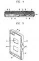
- FIG. 1is a front perspective view of a mobile terminal according to an exemplary embodiment of the present invention
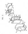
- FIG. 2is a rear perspective view of the mobile terminal according to the exemplary embodiment of the present invention.
- FIG. 3is an exploded perspective view of the mobile terminal according to the exemplary embodiment of the present invention.
- FIG. 4is a sectional view of the mobile terminal according to the exemplary embodiment of the present invention.
- FIGS. 5 and 6are perspective views of a frame of the mobile terminal according to the exemplary embodiment of the present invention.
- FIG. 7is an exploded perspective view showing a mounting structure of a keypad of the frame according to the exemplary embodiment of the present invention.
- FIG. 8is a sectional view taken along line VIII-VIII in FIG. 7 ;
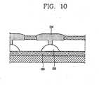
- FIG. 9is a perspective view of a keypad according to the exemplary embodiment of the present invention.
- FIG. 10is a sectional vie taken along line X-X in FIG. 9 ;
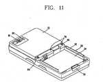
- FIG. 11is a perspective view of the mobile terminal without a battery cover according to the exemplary embodiment of the present invention.
- the mobile terminalincludes a frame 20 with an external circumferential surface being exposed and supporting the entire mobile terminal, a front cover 10 fastened on a front surface of the frame 20, and a rear cover 30 fastened on a rear surface of the frame 20.
- a display 12is mounted in a space between the front cover 10 and the frame 20.
- At least one circuitry supporting substrate 14is mounted in a space between the frame 20 and the rear cover 30 along with a battery 16.
- the front cover 10is at least partially transparent to define a display window 18 allowing information displayed on the display 12 to be seen, and a transparent touch screen 22 is attached on a rear surface of the front cover 10 to allow information to be inputted in a touch manner.
- a substrate 26 having a driving circuit 24 attached at one end thereofis connected with the touch screen 22, and the substrate 26 is connected with the circuitry supporting substrate 14 by a flexible circuitry supporting substrate (not shown).
- a speaker hole 31 for emanating sound generated from the speaker 28is formed at an upper end of the front cover 10, and a keypad mounting hole 33 is formed at a lower end of the front cover 10.
- a keypad 114 that inputs informationis mounted at a lower end of the front cover 10 and is accessible through the keypad mounting hole 33.
- at least one or more keypadsare mounted on the front surface of the front cover 10.
- the frame 20has certain rigidity to maintain overall rigidity of the terminal.
- the frame 20includes a support 32 that has a certain height and is formed in a rectangular shape in a circumferential direction at an edge portion and has an outer surface being exposed, and a partitioning plate 34 formed within the support 32 and partitioning front and rear sides of the frame 32.
- a through hole 36is formed on the partitioning plate 34 to allow a connector, which electrically connects the display 12 mounted on the front surface of the partitioning plate 34 and the circuitry supporting substrate 14 mounted on the rear surface of the partitioning plate 34, to pass therethrough.
- Keypad mounting holes 38are provided in the support 32 to allow access to keypads located therein.
- a camera mounting part 57 on which a camera 61 is mountedis formed at one side of the partitioning plate 34.
- a speaker mounting part 40 on which the speaker 28 is mountedis formed at the side of the camera mounting part 57.
- a first mounting face 42 on which the edge portion of the front cover 10 is mountedis formed at a front edge portion of the frame 20, and a second mounting face 44 on which the edge portion of the rear cover 30 is mounted is formed at a rear edge portion of the frame 20.
- Fastening holes 48are penetratingly formed at four corner portions of the frame 20, through which fasteners pass to be fastened with the front cover 10.
- the fastening structure of the frame 20 and the front cover 10will now be described in detail.
- the front cover 10is mounted on the first mounting face 42 formed on the front surface of the frame 20, and then the fasteners are allowed to pass through the fastening holes in the direction of the front cover 10 from the rear surface of the frame 20 so as to be fastened in the fastening holes formed at the four corner portions of the inner surface of the front cover 10. Because the fasteners pass through a first fastening hole 48 from the rear side to the front side of the frame 20 so as to be fastened with the front cover 20, the front surface of the front cover 10 can have a fine design without a fastener hole for fastening the fasteners.
- Fastening holes 50are formed at both sides of a middle portion of the frame 20 for fastening the frame 20 with the rear cover 30.
- a substrate mounting part 52on which the circuitry supporting substrate 14 is mounted and a battery mounting part 54 on which the battery 16 is mounted.
- a partition 53separates the substrate mounting part 52 and the battery mounting part 54 into first and second receiving spaces.
- the camera mounting partis formed in one of the receiving spaces, preferably the first receiving space.
- First and second keypads 110, 112are mounted on at least one of the four sides of the frame 20, and at least one or more keypads, such as a third keypad 114 is mounted on the front side of the frame 20, and keypad mounting parts 130, 132 and 134 in which the keypads are mounted are formed at the frame 20.
- the first and second keypads 110 and 112are side keypads that are mounted at the side of the frame 20 and input information similar to the third keypad 114.
- the keypadsmay provide many different functions including activating/deactivating the touch screen 22 to prevent inadvertent command entry via the touch screen 22.
- the first and third keypads 110, 114are electrically connected by the flexible circuitry supporting substrate 138.
- a first connector 140is mounted at the first keypad 110 and the first connector 140 is electrically connected with the circuitry supporting substrate 14. Accordingly, the first and third keypads 110 and 114 can be electrically connected with the circuitry supporting substrate 14 by the single connector 140.
- a microphone 120 for generating a soundis mounted at the side of the third keypad 114. Because the microphone 120 is electrically connected with the third keypad 114, the microphone 120 is electrically connected with the circuitry supporting substrate 14 by means of the first connector 140 so that the microphone 120 generates a sound according to an electrical signal applied from the circuitry supporting substrate 14.
- a microphone mounting part 122 in which the microphone 120 is mountedis formed at the frame 20.
- the second keypad 112is a side keypad mounted at the side of the frame 20.
- the second keypad 112has a second connector 142 mounted at one side thereof and is electrically connected with the circuitry supporting substrate 14.
- the first keypad mounting part 130on which the first keypad 110 is mounted, is formed at one side of the frame 20
- the second keypad mounting part 132, on which the second keypad 112 is mountedis formed at the other side of the frame 20
- a third keypad mounting part 134, on which the third keypad 114 is mountedis formed at an edge portion of the front surface of the frame 20.
- the first and second keypad mounting parts 130 and 132are formed in a certain space form by support ribs 146 vertically protruded at left and right edge portions of the frame 20, in which the first and second keypads 110 and 120 are mounted.
- the above-described first, second and third keypads 110, 112, and 114are push type keypads, and, as shown in FIGS. 9 and 10 , they include a keypad circuitry supporting substrate 150 fixed on the keypad mounting part, a dome switch 152 mounted on an upper surface of the keypad circuitry supporting substrate 150 for inputting a signal by a pressing operation, and a key button 154 mounted on an upper surface of the dome switch 152 and exposed so that when a user presses it, it pushes the dome switch 152.
- FIG. 11is a perspective view of the mobile terminal without a battery cover according to the exemplary embodiment of the present invention.
- the rear cover 30is fastened on the substrate mounting part 52 of the frame 20.
- One end of the rear cover 30is hooked at one end of the frame 20 and the other end thereof is fastener-fastened at the frame 20.
- hooking protrusions 56FIG. 6
- the fastener fasting holes 50are formed at both sides of the middle portion of the rear surface of the frame 20.
- Hooks 58FIG. 3
- fastening holes 60are formed at the other end of the rear cover 30 and communicate with the fastening holes 50 so as to be fastened.
- a camera window 62is formed on the rear cover 30 and allows a camera lens of the camera 61 to be exposed.
- a battery cover 66( FIG. 3 ) for protecting the battery is combined on the battery mounting part 54 of the frame 20. Hooks (not shown for clarity) formed at one end of the battery cover 66 are inserted in recesses 70 formed at a middle portion of the frame 20, and the other end of the battery cover 66 is locked by a battery cover locking unit 72 mounted at one end of the frame 20.
- the battery cover 66covers the fastener fasting holes 60 so that the mobile terminal can have an appealing aesthetical design without such holes for fastening.
- the display 12is mounted on the front surface of the frame 20
- the circuitry supporting substrate 14is mounted on the board mounting part 52 of the rear surface of the frame 20
- the battery 16is mounted on the battery mounting part 54 of the rear surface of the frame 20.
- the display 12 and the circuitry supporting substrate 14are connected by the connector.
- the transparent touch screen 22is attached on the inner surface of the front cover 10.
- the first and second keypads 110 and 112are mounted on the first and second keypad mounting parts 130 and 132 formed at the side of the frame 20, and the third keypad 114 is mounted on the third keypad mounting part 134 formed at the front surface of the frame 20.
- the first connector 140 mounted at the first keypad 110 and the second connector 142 mounted at the second keypad 112are connected with the circuitry supporting substrate 14.
- the front cover 10is mounted on the front surface of the frame 20. Namely, after the front cover 10 is mounted on the front surface of the frame 20, the fasteners are inserted into the fastening holes 48 of the frame 20 from the rear side to the front side, so as to be fastened with the front cover 10. Accordingly, because the fastening holes are not exposed from the outer surface of the front cover 10, the terminal can have the appealing aesthetical design.
- the rear cover 30is combined on the rear surface of the frame 20. Specifically, the hooks 58 of the rear cover 30 are hooked to the hooking protrusions 56 formed at one end of the frame 20, and then, the fasteners are allowed to pass through the fastening holes 60 of the rear cover 30 so as to be fastened with the fastening holes 50 of the frame 20.
- the battery cover 66is mounted on the rear surface of the frame 20. Namely, the hooks formed at one end of the battery cover 66 are inserted into the recesses 70 formed at the frame 20, and then, the other end of the battery cover 66 is locked by the battery cover locking unit 72 mounted at one side of the frame 20. Then, because the battery cover 66 covers the fastening holes 60 of the rear cover 30, the fastening holes are not exposed from the rear surface of the terminal, contributing to make the mobile terminal have the fine and neat design.
- the mobile terminal according to the present inventionhas the following advantages.
- the terminalcan become thin and have the appealing aesthetical design.
Landscapes
- Engineering & Computer Science (AREA)
- Computer Hardware Design (AREA)
- Theoretical Computer Science (AREA)
- General Engineering & Computer Science (AREA)
- Human Computer Interaction (AREA)
- Physics & Mathematics (AREA)
- General Physics & Mathematics (AREA)
- Signal Processing (AREA)
- Telephone Set Structure (AREA)
- Telephone Function (AREA)
- Piezo-Electric Or Mechanical Vibrators, Or Delay Or Filter Circuits (AREA)
- Casings For Electric Apparatus (AREA)
Abstract
Description
- The present invention relates to a mobile terminal and, more particularly, to a mobile terminal that is thin.
- In general, a mobile terminal includes a display unit having a display to display information and a terminal body that is connected to the display unit by a hinge connection unit. The terminal body has a keypad that is mounted on its front surface and inputs information and a battery that is mounted on its rear surface. A speaker that generates a sound is mounted at one end of the display unit and a microphone that inputs a sound is mounted at one end of the terminal body.
- In the related art mobile terminal, when the display unit is rotated centering around the hinge connection unit and opened, the display and the keypad are exposed to allow the terminal to be used in a communication mode to transmit and receive data.
- However, the related art mobile terminal has the following problem. That is, because the two bodies are connected to allow opening and closing thereof, the overall thickness of the terminal is undesirably large, and thus a larger sized display cannot be implemented due to limitations in size expansion.
US 6,760,074 B1 discloses a computer device with a middle case interposed between a top case and a bottom case. The top, middle and bottom cases are combined to form a cabinet, in which a liquid crystal display panel, a main board, a CCD camera and signal processing circuitry for the CCD camera are disposed. The display panel of the device is arranged on the top case of the device. The middle case holds what is referred to as a function extension unit in this document.US 2004/0042160 A1 discloses an electronic touch-screen device in which an LCD panel and a digitizer panel are attached to a front cover of the device and control circuitry is attached to a back cover of the device.EP 1 471 716 A2 discloses a mobile device having a case which forms a platform arranged on the front of the case to receive a keypad and a keyboard PCB. The case provides side walls which surround the peripheral edges of a display, which can be configured as a touch screen. The display is viewable from the top of the mobile device through an opening in the case. A main PCB extends under the platform and the display and is covered at its bottom side by a back cover of the mobile device.- One aspect of the exemplary embodiments is to provide a mobile terminal which is thin and has an appealing aesthetical design by forming front and rear covers on both sides of a frame positioned at a middle portion of the mobile terminal.
- According to this invention, a mobile terminal according to claim 1 is provided. Preferred embodiments are defined in the dependent claims.
- A speaker hole may be located at an upper portion of the front cover.
- A keypad mounting part may be located in the front cover.
- The front cover may be fastened by fasteners to the frame in a direction from the frame towards the front cover to prevent the fasteners from being exposed.
- The frame may include a support unit having an outer surface that is exposed, the support unit defining the edge of the frame, wherein the partitioning plate divides the frame into the front side and the rear side. In addition, the partitioning plate may include a through hole to allow a connector to connect the display to the circuitry supporting substrate through the partitioning plate.
- In a further aspect, the first and second receiving spaces are disposed horizontal to the rear side of the frame.
- In still another aspect, the rear cover covers the first receiving space and a battery cover is detachably mounted to cover the second receiving space.
- A camera window may be located in the rear cover.
- The rear cover may include a plurality of hooks at one end and a plurality of fastening holes at the other end, the one end of the rear cover being fastened to the frame in a hooking manner and the other end thereof fastened to the frame via fasteners passing through the fastening holes. In addition, the battery cover may cover the fastening holes of the rear cover.
- At least one keypad for inputting information may be mounted on at least one of the four sides of the frame, and at least one keypad may be mounted on the front side of the frame. In addition, the at least one keypad for inputting information mounted on at least one of the four sides of the frame may include first and second keypads, each of the first and second keypads being located at opposite sides of the frame, and the at least one keypad mounted on the front side of the frame may be a third keypad located at an edge portion of the front surface of the frame. The keypads may be push type keypads that input signals according to a pressing operation.
- A microphone may be mounted at the third keypad and the microphone and the third keypad are electrically connected.
- The first and third keypads may be connected by a flexible circuitry supporting substrate, and the first keypad may include a first connector electrically connectable to a circuitry supporting substrate. In addition, the second keypad may include a second connector electrically connectable to a circuitry supporting substrate.
- The mobile terminal may form a body having a front side and a rear side, at least a majority of the front side being a transparent portion, an outer surface of the front side including the transparent portion being substantially flat, the display located in the body and visible through the transparent portion of the front side of the body, the touch screen located between the transparent portion and the display, and the camera located at the rear side of the body.
- In another aspect, at least one key may be arranged on a side of the body for inputting information.
- In still another aspect, a speaker hole may be located at the front side.
- In another aspect, a microphone may be located in the body.
- In yet another aspect, the terminal can transmit and/or receive data.
- Further scope of applicability of the present application will become more apparent from the detailed description given hereinafter. However, it should be understood that the detailed description and specific examples, while indicating preferred embodiments of the invention, are given by way of illustration only.
- The accompanying drawings, which are included to provide a further understanding of the invention illustrate embodiments of the invention and together with the description serve to explain the principles of the invention.
- In the drawings:
FIG. 1 is a front perspective view of a mobile terminal according to an exemplary embodiment of the present invention;FIG. 2 is a rear perspective view of the mobile terminal according to the exemplary embodiment of the present invention;FIG. 3 is an exploded perspective view of the mobile terminal according to the exemplary embodiment of the present invention;FIG. 4 is a sectional view of the mobile terminal according to the exemplary embodiment of the present invention;FIGS. 5 and6 are perspective views of a frame of the mobile terminal according to the exemplary embodiment of the present invention;FIG. 7 is an exploded perspective view showing a mounting structure of a keypad of the frame according to the exemplary embodiment of the present invention;FIG. 8 is a sectional view taken along line VIII-VIII inFIG. 7 ;FIG. 9 is a perspective view of a keypad according to the exemplary embodiment of the present invention;FIG. 10 is a sectional vie taken along line X-X inFIG. 9 ; andFIG. 11 is a perspective view of the mobile terminal without a battery cover according to the exemplary embodiment of the present invention.- A mobile terminal according to an exemplary embodiment of the present invention will now be described in detail with reference to the accompanying drawings.
- The mobile terminal according to the exemplary embodiment of the present invention includes a
frame 20 with an external circumferential surface being exposed and supporting the entire mobile terminal, afront cover 10 fastened on a front surface of theframe 20, and arear cover 30 fastened on a rear surface of theframe 20. Adisplay 12 is mounted in a space between thefront cover 10 and theframe 20. At least onecircuitry supporting substrate 14 is mounted in a space between theframe 20 and therear cover 30 along with abattery 16. - The
front cover 10 is at least partially transparent to define adisplay window 18 allowing information displayed on thedisplay 12 to be seen, and atransparent touch screen 22 is attached on a rear surface of thefront cover 10 to allow information to be inputted in a touch manner. - A
substrate 26 having adriving circuit 24 attached at one end thereof is connected with thetouch screen 22, and thesubstrate 26 is connected with thecircuitry supporting substrate 14 by a flexible circuitry supporting substrate (not shown). - A
speaker hole 31 for emanating sound generated from thespeaker 28 is formed at an upper end of thefront cover 10, and akeypad mounting hole 33 is formed at a lower end of thefront cover 10. Akeypad 114 that inputs information is mounted at a lower end of thefront cover 10 and is accessible through thekeypad mounting hole 33. Preferably, at least one or more keypads are mounted on the front surface of thefront cover 10. - The
frame 20 has certain rigidity to maintain overall rigidity of the terminal. Theframe 20 includes asupport 32 that has a certain height and is formed in a rectangular shape in a circumferential direction at an edge portion and has an outer surface being exposed, and apartitioning plate 34 formed within thesupport 32 and partitioning front and rear sides of theframe 32. - A through
hole 36 is formed on thepartitioning plate 34 to allow a connector, which electrically connects thedisplay 12 mounted on the front surface of thepartitioning plate 34 and thecircuitry supporting substrate 14 mounted on the rear surface of thepartitioning plate 34, to pass therethrough.Keypad mounting holes 38 are provided in thesupport 32 to allow access to keypads located therein. - A
camera mounting part 57 on which acamera 61 is mounted is formed at one side of thepartitioning plate 34. Aspeaker mounting part 40 on which thespeaker 28 is mounted is formed at the side of thecamera mounting part 57. - A first mounting
face 42 on which the edge portion of thefront cover 10 is mounted is formed at a front edge portion of theframe 20, and a second mountingface 44 on which the edge portion of therear cover 30 is mounted is formed at a rear edge portion of theframe 20. - Fastening holes 48 are penetratingly formed at four corner portions of the
frame 20, through which fasteners pass to be fastened with thefront cover 10. - The fastening structure of the
frame 20 and thefront cover 10 will now be described in detail. Thefront cover 10 is mounted on the first mountingface 42 formed on the front surface of theframe 20, and then the fasteners are allowed to pass through the fastening holes in the direction of thefront cover 10 from the rear surface of theframe 20 so as to be fastened in the fastening holes formed at the four corner portions of the inner surface of thefront cover 10. Because the fasteners pass through afirst fastening hole 48 from the rear side to the front side of theframe 20 so as to be fastened with thefront cover 20, the front surface of thefront cover 10 can have a fine design without a fastener hole for fastening the fasteners. - Fastening holes 50 are formed at both sides of a middle portion of the
frame 20 for fastening theframe 20 with therear cover 30. - On the rear surface of the
frame 20, there are formed asubstrate mounting part 52 on which thecircuitry supporting substrate 14 is mounted and abattery mounting part 54 on which thebattery 16 is mounted. Apartition 53 separates thesubstrate mounting part 52 and thebattery mounting part 54 into first and second receiving spaces. The camera mounting part is formed in one of the receiving spaces, preferably the first receiving space. - First and
second keypads frame 20, and at least one or more keypads, such as athird keypad 114 is mounted on the front side of theframe 20, andkeypad mounting parts frame 20. The first andsecond keypads frame 20 and input information similar to thethird keypad 114. The keypads may provide many different functions including activating/deactivating thetouch screen 22 to prevent inadvertent command entry via thetouch screen 22. - In the exemplary embodiment shown, the first and
third keypads circuitry supporting substrate 138. Afirst connector 140 is mounted at thefirst keypad 110 and thefirst connector 140 is electrically connected with thecircuitry supporting substrate 14. Accordingly, the first andthird keypads circuitry supporting substrate 14 by thesingle connector 140. - A
microphone 120 for generating a sound is mounted at the side of thethird keypad 114. Because themicrophone 120 is electrically connected with thethird keypad 114, themicrophone 120 is electrically connected with thecircuitry supporting substrate 14 by means of thefirst connector 140 so that themicrophone 120 generates a sound according to an electrical signal applied from thecircuitry supporting substrate 14. - A
microphone mounting part 122 in which themicrophone 120 is mounted is formed at theframe 20. - The
second keypad 112 is a side keypad mounted at the side of theframe 20. Thesecond keypad 112 has asecond connector 142 mounted at one side thereof and is electrically connected with thecircuitry supporting substrate 14. - In the exemplary embodiment shown, the first
keypad mounting part 130, on which thefirst keypad 110 is mounted, is formed at one side of theframe 20, the secondkeypad mounting part 132, on which thesecond keypad 112 is mounted, is formed at the other side of theframe 20, and a thirdkeypad mounting part 134, on which thethird keypad 114 is mounted, is formed at an edge portion of the front surface of theframe 20. - Herein, as shown in
FIG. 8 , the first and secondkeypad mounting parts support ribs 146 vertically protruded at left and right edge portions of theframe 20, in which the first andsecond keypads - The above-described first, second and
third keypads FIGS. 9 and10 , they include a keypadcircuitry supporting substrate 150 fixed on the keypad mounting part, adome switch 152 mounted on an upper surface of the keypadcircuitry supporting substrate 150 for inputting a signal by a pressing operation, and akey button 154 mounted on an upper surface of thedome switch 152 and exposed so that when a user presses it, it pushes thedome switch 152. FIG. 11 is a perspective view of the mobile terminal without a battery cover according to the exemplary embodiment of the present invention.- The
rear cover 30 is fastened on thesubstrate mounting part 52 of theframe 20. One end of therear cover 30 is hooked at one end of theframe 20 and the other end thereof is fastener-fastened at theframe 20. Namely, hooking protrusions 56 (FIG. 6 ) are formed to be protruded in an inward direction at an edge portion of the rear surface of theframe 20, and the fastener fasting holes 50 are formed at both sides of the middle portion of the rear surface of theframe 20. Hooks 58 (FIG. 3 ) to engage the hookingprotrusions 56 are formed at one end of therear cover 30, and fastening holes 60 are formed at the other end of therear cover 30 and communicate with the fastening holes 50 so as to be fastened. - A
camera window 62 is formed on therear cover 30 and allows a camera lens of thecamera 61 to be exposed. - An assembling process of the
rear cover 30 will now be described. First, thehooks 58 formed at one end of the rear cove r30 are inserted to engage the hookingprotrusions 56 of theframe 20. Thereafter, the fasteners are fastened in the fastening holes 60 formed at therear cover 30 to make therear cover 30 fastened to theframe 20. - A battery cover 66 (
FIG. 3 ) for protecting the battery is combined on thebattery mounting part 54 of theframe 20. Hooks (not shown for clarity) formed at one end of thebattery cover 66 are inserted inrecesses 70 formed at a middle portion of theframe 20, and the other end of thebattery cover 66 is locked by a batterycover locking unit 72 mounted at one end of theframe 20. - The
battery cover 66 covers the fastener fasting holes 60 so that the mobile terminal can have an appealing aesthetical design without such holes for fastening. - The assembling process of the mobile terminal according to the present invention will now be described.
- The
display 12 is mounted on the front surface of theframe 20, thecircuitry supporting substrate 14 is mounted on theboard mounting part 52 of the rear surface of theframe 20, and thebattery 16 is mounted on thebattery mounting part 54 of the rear surface of theframe 20. Thedisplay 12 and thecircuitry supporting substrate 14 are connected by the connector. - The
transparent touch screen 22 is attached on the inner surface of thefront cover 10. The first andsecond keypads keypad mounting parts frame 20, and thethird keypad 114 is mounted on the thirdkeypad mounting part 134 formed at the front surface of theframe 20. And then, thefirst connector 140 mounted at thefirst keypad 110 and thesecond connector 142 mounted at thesecond keypad 112 are connected with thecircuitry supporting substrate 14. - Thereafter, the
front cover 10 is mounted on the front surface of theframe 20. Namely, after thefront cover 10 is mounted on the front surface of theframe 20, the fasteners are inserted into the fastening holes 48 of theframe 20 from the rear side to the front side, so as to be fastened with thefront cover 10. Accordingly, because the fastening holes are not exposed from the outer surface of thefront cover 10, the terminal can have the appealing aesthetical design. - The
rear cover 30 is combined on the rear surface of theframe 20. Specifically, thehooks 58 of therear cover 30 are hooked to the hookingprotrusions 56 formed at one end of theframe 20, and then, the fasteners are allowed to pass through the fastening holes 60 of therear cover 30 so as to be fastened with the fastening holes 50 of theframe 20. - The
battery cover 66 is mounted on the rear surface of theframe 20. Namely, the hooks formed at one end of thebattery cover 66 are inserted into therecesses 70 formed at theframe 20, and then, the other end of thebattery cover 66 is locked by the batterycover locking unit 72 mounted at one side of theframe 20. Then, because thebattery cover 66 covers the fastening holes 60 of therear cover 30, the fastening holes are not exposed from the rear surface of the terminal, contributing to make the mobile terminal have the fine and neat design. - As so far described, the mobile terminal according to the present invention has the following advantages.
- That is, because the front cover is combined on the front surface of the frame with its outer surface being exposed, the rear cover is combined on the rear surface of the frame, the display is mounted between the frame and the front cover, and the circuitry supporting substrate is mounted between the frame and the rear cover, the terminal can become thin and have the appealing aesthetical design.
Claims (20)
- A mobile terminal comprising:- a frame (20) including a partitioning plate (34) dividing the frame into a front side and a rear side, wherein the rear side of the frame has a first receiving space (52) and a second receiving space (54) located beside one another;- a front cover (10) disposed to at least partially cover the front side of the frame, wherein the front cover has a transparent portion forming a display window (18);- a display (12) mounted in a space between the front cover and the partitioning plate (34), the display being visible through the display window (18);- a touch screen (22) located between the front cover (10) and the display (12), the touch screen permitting transmission of a signal when the transparent portion is contacted;- a pair of circuitry supporting substrates (14) located in the first receiving space (52) one above the other;- a camera (62) located in the first receiving space (52) ;- a battery (16) located in the second receiving space (54); and- a rear cover (30) disposed to cover at least the first receiving space (52).
- The terminal of claim 1, wherein the display (12) is mounted on a front surface of the frame (20).
- The terminal of claim 1 or 2, wherein the touch screen (22) is attached to an inner surface of the front cover (10).
- The terminal of any one preceding claim, wherein a speaker hole (31) is formed at an upper portion of the front cover (10).
- The terminal of any one preceding claim, wherein a keypad mounting part (33) is formed on the front cover (10).
- The terminal of any one preceding claim, wherein the front cover (10) is fastened by fasteners to the frame (20) in a direction from the frame towards the front cover to prevent the fasteners from being exposed.
- The terminal of any one preceding claim, wherein the frame (20) includes a support unit (32) having an outer surface that is exposed, the support unit defining the edge of the frame.
- The terminal of any one preceding claim, wherein the partitioning plate (34) includes a through hole (36) to allow a connector to connect the display (12) to a circuitry supporting substrate (14) through the partitioning plate.
- The terminal of any one preceding claim, wherein the first and second receiving spaces (52, 54) are disposed horizontally to the rear side of the frame (20).
- The terminal of any one preceding claim, wherein the rear cover (30) covers the first receiving space (52) and a battery cover (66) is detachably mounted to cover the second receiving space (54).
- The terminal of claim 10, wherein a camera window (62) is located in the rear cover (30).
- The terminal of claim 10 or 11, wherein the rear cover (30) includes a plurality of hooks (58) at one end and a plurality of fastening holes (60) at the other end, the one end of the rear cover is fastened to the frame (20) in a hooking manner and the other end thereof is fastened to the frame via fasteners passing through the fastening holes.
- The terminal of claim 12, wherein the fastening holes (60) of the rear cover (30) are covered by the battery cover (66).
- The terminal of any one preceding claim, wherein at least one keypad for inputting information is mounted on at least one of the four lateral sides of the frame (20), and at least one keypad is mounted on the front side of the frame (20).
- The terminal of claim 14, wherein the at least one keypad mounted on at least one of the four lateral sides of the frame (20) includes first and second keypads (110, 112) located at opposite sides of the frame, and the at least one keypad mounted on the front side of the frame is a third keypad (114) located at an edge portion of the front surface of the frame.
- The terminal of claim 14 or 15, wherein the keypads are push type keypads that input signals according to a pressing operation.
- The terminal of claim 16, wherein a microphone (120) is mounted at the third keypad (114) and the microphone and the third keypad are electrically connected.
- The terminal of claim 15, wherein the first and third keypads (110, 114) are connected by a flexible circuitry supporting substrate (138), and the first keypad includes a first connector (140) electrically connectable to a circuitry supporting substrate (14).
- The terminal of claim 18, wherein the second keypad (112) includes a second connector (142) electrically connectable to a circuitry supporting substrate (14).
- The terminal of any one preceding claim, wherein the first and second receiving spaces (52, 54) are separated by a partitioning rib (53) formed on the partitioning plate (34).
Priority Applications (1)
| Application Number | Priority Date | Filing Date | Title |
|---|---|---|---|
| DE202007018461UDE202007018461U1 (en) | 2006-07-14 | 2007-07-13 | Mobile terminal |
Applications Claiming Priority (2)
| Application Number | Priority Date | Filing Date | Title |
|---|---|---|---|
| KR1020060066575AKR100757448B1 (en) | 2006-07-14 | 2006-07-14 | Handheld terminal |
| KR1020060071042AKR100813692B1 (en) | 2006-07-27 | 2006-07-27 | Handheld terminal |
Publications (3)
| Publication Number | Publication Date |
|---|---|
| EP1879363A2 EP1879363A2 (en) | 2008-01-16 |
| EP1879363A3 EP1879363A3 (en) | 2008-03-05 |
| EP1879363B1true EP1879363B1 (en) | 2010-09-22 |
Family
ID=38566928
Family Applications (1)
| Application Number | Title | Priority Date | Filing Date |
|---|---|---|---|
| EP07013833AActiveEP1879363B1 (en) | 2006-07-14 | 2007-07-13 | Mobile terminal |
Country Status (9)
| Country | Link |
|---|---|
| US (2) | US7492602B2 (en) |
| EP (1) | EP1879363B1 (en) |
| AT (1) | ATE482563T1 (en) |
| BR (1) | BRPI0702979B1 (en) |
| CA (1) | CA2593691C (en) |
| DE (3) | DE102007032755B4 (en) |
| MX (1) | MX2007008633A (en) |
| RU (1) | RU2385533C2 (en) |
| TW (1) | TWI465173B (en) |
Families Citing this family (65)
| Publication number | Priority date | Publication date | Assignee | Title |
|---|---|---|---|---|
| JP2003229938A (en)* | 2002-02-04 | 2003-08-15 | Matsushita Electric Ind Co Ltd | Foldable mobile phone device |
| JP4531051B2 (en)* | 2004-08-19 | 2010-08-25 | 富士通株式会社 | Case structure and electronic apparatus having the same |
| US7492602B2 (en)* | 2006-07-14 | 2009-02-17 | Lg Electronics Inc. | Mobile terminal |
| KR100810264B1 (en)* | 2006-07-20 | 2008-03-07 | 삼성전자주식회사 | Portable terminal with unlocking device |
| USD566588S1 (en)* | 2007-03-05 | 2008-04-15 | Garmin Ltd. | Navigation device |
| FR2923070B1 (en)* | 2007-10-26 | 2010-07-30 | Archos | BOX-SCREEN ASSEMBLY, METHOD FOR MANUFACTURING SAME, AND PORTABLE ELECTRONIC APPARATUS THUS EQUIPPED |
| KR100904960B1 (en)* | 2007-11-09 | 2009-06-26 | 엘지전자 주식회사 | Handheld terminal |
| US8619039B2 (en)* | 2007-12-21 | 2013-12-31 | Motorola Mobility Llc | Translucent touch screen devices including low resistive mesh |
| CA126550S (en)* | 2008-02-08 | 2009-05-01 | Toshiba Kk | Portabile information terminal |
| CA126548S (en)* | 2008-02-08 | 2009-05-01 | Toshiba Kk | Portable information terminal |
| US20090205983A1 (en)* | 2008-02-19 | 2009-08-20 | Sony Ericsson Mobile Communications Ab | Metal cover for portable electronic device |
| US8417298B2 (en) | 2008-04-01 | 2013-04-09 | Apple Inc. | Mounting structures for portable electronic devices |
| JP5115310B2 (en)* | 2008-04-28 | 2013-01-09 | 富士通株式会社 | Mobile terminal device |
| USD596605S1 (en)* | 2008-05-06 | 2009-07-21 | Samsung Electronics Co., Ltd. | Mobile phone |
| KR101437994B1 (en)* | 2008-06-25 | 2014-09-05 | 엘지전자 주식회사 | Mobile terminal |
| USD600690S1 (en)* | 2008-07-09 | 2009-09-22 | Kabushiki Kaisha Toshiba | Portable information terminal unit |
| CN101640137B (en)* | 2008-07-30 | 2013-04-24 | 深圳富泰宏精密工业有限公司 | Button structure of electronic device |
| CA129633S (en)* | 2008-08-19 | 2009-11-23 | Lg Electronics Inc | Mobile phone |
| KR101592296B1 (en)* | 2008-09-03 | 2016-02-05 | 엘지전자 주식회사 | Mobile terminal and its object selection and execution method |
| RU2610581C2 (en)* | 2008-09-05 | 2017-02-13 | Эппл Инк. | Portable computing device |
| KR101464537B1 (en)* | 2008-10-01 | 2014-11-24 | 삼성전자주식회사 | User interface module of digital camera and digital camera having same |
| USD624517S1 (en)* | 2008-12-16 | 2010-09-28 | Lg Electronics Inc. | Mobile phone |
| CN101753647A (en)* | 2008-12-22 | 2010-06-23 | 鸿富锦精密工业(深圳)有限公司 | Divide-body mobile phone |
| CN201393243Y (en)* | 2009-03-13 | 2010-01-27 | 鸿富锦精密工业(深圳)有限公司 | Button fixed structure of mobile device |
| US9106042B2 (en)* | 2009-06-30 | 2015-08-11 | Motorola Solutions, Inc. | Battery connector system |
| KR101578430B1 (en)* | 2009-07-13 | 2015-12-18 | 엘지전자 주식회사 | Mobile terminal |
| US9100098B2 (en) | 2009-07-14 | 2015-08-04 | Bluebird Soft Co., Ltd. | Mobile terminal |
| TWD139828S1 (en)* | 2009-07-31 | 2011-04-01 | 宏達國際電子股份有限公司 | Mobile phone |
| DE202009016312U1 (en)* | 2009-12-02 | 2010-04-15 | Surftable Ag, Immensee | Housing for display and / or control and / or control unit and device for this purpose |
| US8432678B2 (en) | 2010-01-06 | 2013-04-30 | Apple Inc. | Component assembly |
| US8797721B2 (en) | 2010-02-02 | 2014-08-05 | Apple Inc. | Portable electronic device housing with outer glass surfaces |
| US8913395B2 (en)* | 2010-02-02 | 2014-12-16 | Apple Inc. | High tolerance connection between elements |
| US9535500B2 (en)* | 2010-03-01 | 2017-01-03 | Blackberry Limited | Method of providing tactile feedback and apparatus |
| US8264837B2 (en)* | 2010-04-19 | 2012-09-11 | Apple Inc. | Systems and methods for cover assembly retention of a portable electronic device |
| US9030308B1 (en)* | 2010-07-02 | 2015-05-12 | Amazon Technologies, Inc. | Piezoelectric haptic actuator integration |
| US8477492B2 (en)* | 2010-08-19 | 2013-07-02 | Apple Inc. | Formed PCB |
| KR101107015B1 (en)* | 2010-09-02 | 2012-01-25 | (주)블루버드 소프트 | Mobile terminal and manufacturing method thereof |
| KR101107016B1 (en) | 2010-09-02 | 2012-01-25 | (주)블루버드 소프트 | Mobile terminal |
| WO2012090031A1 (en)* | 2010-12-31 | 2012-07-05 | Nokia Corporation | A display apparatus producing audio and haptic output |
| JP5621690B2 (en)* | 2011-03-31 | 2014-11-12 | 富士通株式会社 | Electronic device and flexible substrate |
| KR200471325Y1 (en) | 2011-07-13 | 2014-02-19 | 모토로라 모빌리티 엘엘씨 | Mobile electronic device with enhanced tolerance accumulator |
| BR202012004685Y1 (en) | 2011-07-13 | 2019-04-02 | Google Technology Holdings LLC | MOBILE ELECTRONIC DEVICE WITH IMPROVED LAMINATED CONSTRUCTION |
| BR202012004687U8 (en)* | 2011-07-13 | 2016-11-22 | Motorola Mobility Inc | MOBILE ELECTRONIC DEVICE WITH IMPROVED CHASSIS |
| BR202012004686Y1 (en) | 2011-07-13 | 2019-05-14 | Google Technology Holdings LLC | MOBILE ELECTRONIC DEVICE WITH ENHANCED IMPACT REDUCTION. |
| US9182935B2 (en) | 2011-09-27 | 2015-11-10 | Z124 | Secondary single screen mode activation through menu option |
| CN102377851A (en)* | 2011-10-31 | 2012-03-14 | 深圳市中创投资股份有限公司 | Flat mobile phone-protecting jacket with touch screen and iPhone4 mobile phone-protecting jacket |
| US20130135795A1 (en)* | 2011-11-30 | 2013-05-30 | Htc Corporation | Electronic device |
| KR20130074432A (en)* | 2011-12-26 | 2013-07-04 | 삼성디스플레이 주식회사 | Glass panel for mobile device, method for manufacturing the same, and mobile device using the same |
| DE102013106305A1 (en)* | 2012-06-20 | 2013-12-24 | Samsung Electro-Mechanics Co., Ltd. | Portable terminal |
| JP6028447B2 (en)* | 2012-08-08 | 2016-11-16 | 富士通株式会社 | Electronic equipment |
| KR20140036624A (en)* | 2012-09-17 | 2014-03-26 | 엘지전자 주식회사 | Mobile terminal |
| FR3003963B1 (en)* | 2013-03-29 | 2016-12-30 | Dav | INTERFACE MODULE |
| KR20250130688A (en)* | 2013-07-16 | 2025-09-02 | 가부시키가이샤 한도오따이 에네루기 켄큐쇼 | Electronic device |
| USD744469S1 (en)* | 2013-08-21 | 2015-12-01 | Lg Electronics Inc. | Display for mobile phone |
| USD740266S1 (en)* | 2013-08-21 | 2015-10-06 | Lg Electronics Inc. | Main body for mobile phone |
| US9520036B1 (en)* | 2013-09-18 | 2016-12-13 | Amazon Technologies, Inc. | Haptic output generation with dynamic feedback control |
| CN103747641A (en)* | 2014-01-26 | 2014-04-23 | 小米科技有限责任公司 | Mobile terminal |
| KR20160129336A (en)* | 2015-04-30 | 2016-11-09 | 엘지전자 주식회사 | Mobile terminal |
| EP3104250A1 (en) | 2015-06-10 | 2016-12-14 | FairPhone B.V. | Modular electronic device |
| KR102396460B1 (en)* | 2015-10-29 | 2022-05-11 | 엘지디스플레이 주식회사 | Curved display device and electronic device comprising the same |
| US9900999B1 (en)* | 2017-02-03 | 2018-02-20 | Google Inc. | Circuit board architecture for an electronic device |
| CN111327732B (en)* | 2018-12-17 | 2025-05-13 | 珠海市魅族科技有限公司 | Camera assembly mounting structure and terminal |
| CN110138935A (en)* | 2019-05-05 | 2019-08-16 | Oppo广东移动通信有限公司 | Display assembly and terminal equipment |
| EP4198682A4 (en)* | 2020-12-31 | 2024-03-06 | Samsung Electronics Co., Ltd. | Electronic device comprising speaker |
| TWI891099B (en)* | 2023-10-27 | 2025-07-21 | 宏碁股份有限公司 | Laptop computer |
Family Cites Families (19)
| Publication number | Priority date | Publication date | Assignee | Title |
|---|---|---|---|---|
| JPH09231245A (en) | 1996-02-22 | 1997-09-05 | Hitachi Ltd | Portable information terminal |
| US5749457A (en)* | 1996-12-23 | 1998-05-12 | Motorola Inc. | Electronic device with switch and pivotable actuator assembly |
| KR100303082B1 (en) | 1997-10-13 | 2001-11-22 | 윤종용 | Multimedia device using portable computer |
| GB2330980A (en) | 1997-10-31 | 1999-05-05 | Ericsson Omc Limited | Mobile telephone with transparent loudspeaker panel |
| US6148183A (en)* | 1997-12-31 | 2000-11-14 | Motorola, Inc. | Switch assembly for an electronic device |
| US6128515A (en)* | 1998-02-27 | 2000-10-03 | Garmin Corporation | Combined global positioning and wireless telephone device |
| JP2002521971A (en)* | 1998-07-28 | 2002-07-16 | コーニンクレッカ フィリップス エレクトロニクス エヌ ヴィ | Digital handheld keyboard-oriented device with camera providing multiple key data and control inputs, display, wireless communication and data processing, and communication |
| JP4272290B2 (en)* | 1999-02-26 | 2009-06-03 | 株式会社日立製作所 | Portable electronic calculator |
| TWI237988B (en)* | 2000-03-09 | 2005-08-11 | Compal Electronics Inc | Cellular telephone |
| US6747224B1 (en)* | 2001-03-27 | 2004-06-08 | Palmone, Inc. | Integrated keypad interface for a personal digital assistant device |
| KR100655549B1 (en)* | 2002-08-29 | 2006-12-07 | 엘지전자 주식회사 | Portable hybrid computer |
| US20040046739A1 (en)* | 2002-09-11 | 2004-03-11 | Palm, Inc. | Pliable device navigation method and apparatus |
| US7203467B2 (en) | 2003-04-14 | 2007-04-10 | Microsoft Corporation | Protective case for electronics in a mobile device |
| RU31183U1 (en)* | 2003-04-23 | 2003-07-20 | Мосиенко Сергей Александрович | Mobile communication terminal |
| JP2005173509A (en) | 2003-12-15 | 2005-06-30 | Fujitsu Ltd | Electronic equipment |
| EP1603308B1 (en) | 2004-06-01 | 2006-11-22 | Research In Motion Limited | Display cover for a communication device |
| KR100676673B1 (en) | 2004-12-13 | 2007-02-01 | 한국전자통신연구원 | Physical Simulation Acceleration System and Method |
| KR20060071042A (en) | 2004-12-21 | 2006-06-26 | 주식회사 대우일렉트로닉스 | How to adjust the angle of the remote sensor |
| US7492602B2 (en)* | 2006-07-14 | 2009-02-17 | Lg Electronics Inc. | Mobile terminal |
- 2007
- 2007-07-12USUS11/777,131patent/US7492602B2/enactiveActive
- 2007-07-13ATAT07013833Tpatent/ATE482563T1/ennot_activeIP Right Cessation
- 2007-07-13CACA2593691Apatent/CA2593691C/enactiveActive
- 2007-07-13EPEP07013833Apatent/EP1879363B1/enactiveActive
- 2007-07-13DEDE102007032755.4Apatent/DE102007032755B4/enactiveActive
- 2007-07-13DEDE202007018461Upatent/DE202007018461U1/ennot_activeExpired - Lifetime
- 2007-07-13RURU2007126822/02Apatent/RU2385533C2/enactive
- 2007-07-13TWTW096125668Apatent/TWI465173B/ennot_activeIP Right Cessation
- 2007-07-13DEDE602007009342Tpatent/DE602007009342D1/enactiveActive
- 2007-07-16BRBRPI0702979-9Apatent/BRPI0702979B1/enactiveIP Right Grant
- 2007-07-16MXMX2007008633Apatent/MX2007008633A/enactiveIP Right Grant
- 2009
- 2009-01-08USUS12/350,891patent/US7656675B2/enactiveActive
Also Published As
| Publication number | Publication date |
|---|---|
| BRPI0702979B1 (en) | 2019-11-19 |
| DE102007032755A1 (en) | 2008-02-07 |
| US7656675B2 (en) | 2010-02-02 |
| TWI465173B (en) | 2014-12-11 |
| US20080014787A1 (en) | 2008-01-17 |
| TW200806151A (en) | 2008-01-16 |
| RU2385533C2 (en) | 2010-03-27 |
| DE602007009342D1 (en) | 2010-11-04 |
| BRPI0702979A (en) | 2008-02-26 |
| DE102007032755B4 (en) | 2021-08-05 |
| US20090116202A1 (en) | 2009-05-07 |
| MX2007008633A (en) | 2009-01-07 |
| EP1879363A3 (en) | 2008-03-05 |
| ATE482563T1 (en) | 2010-10-15 |
| CA2593691A1 (en) | 2008-01-14 |
| CA2593691C (en) | 2015-12-01 |
| US7492602B2 (en) | 2009-02-17 |
| DE202007018461U1 (en) | 2008-08-07 |
| EP1879363A2 (en) | 2008-01-16 |
| RU2007126822A (en) | 2009-01-20 |
Similar Documents
| Publication | Publication Date | Title |
|---|---|---|
| EP1879363B1 (en) | Mobile terminal | |
| US8988865B2 (en) | Electronic apparatus | |
| JP2004514929A (en) | Foldable multi-display device | |
| US6995975B2 (en) | Electronic apparatus comprising keyboard-mounted housing | |
| JP2018120060A (en) | Display and electronic apparatus | |
| CN103189812A (en) | Laptops with exposed areas | |
| US9084344B2 (en) | Display apparatus | |
| TWI232077B (en) | LCD device having a combined bezel and front housing | |
| US7486340B2 (en) | Display apparatus | |
| US7447004B2 (en) | Portable display apparatus | |
| JP2006100671A (en) | Electronics | |
| KR101164822B1 (en) | Information processing apparatus and manufacturing method for the same | |
| US20070202720A1 (en) | Inseparable PCB module | |
| KR101966256B1 (en) | Assembling structure of housing for portable terminal | |
| KR20080010693A (en) | Handheld terminal | |
| JP5296562B2 (en) | Portable electronic devices | |
| JP2005100173A (en) | Information equipment | |
| CA2767373A1 (en) | Retention mechanism for a navigation tool | |
| JP2008009904A (en) | Electronic device | |
| JP4804434B2 (en) | Mobile terminal device | |
| KR101667429B1 (en) | Portable electronic apparatus | |
| KR20110068799A (en) | Portable display | |
| KR200333168Y1 (en) | Monitor | |
| KR200181699Y1 (en) | Liquid crystal display for portable radiotelephone | |
| KR20060040389A (en) | Display device |
Legal Events
| Date | Code | Title | Description |
|---|---|---|---|
| PUAI | Public reference made under article 153(3) epc to a published international application that has entered the european phase | Free format text:ORIGINAL CODE: 0009012 | |
| AK | Designated contracting states | Kind code of ref document:A2 Designated state(s):AT BE BG CH CY CZ DE DK EE ES FI FR GB GR HU IE IS IT LI LT LU LV MC MT NL PL PT RO SE SI SK TR | |
| AX | Request for extension of the european patent | Extension state:AL BA HR MK YU | |
| PUAL | Search report despatched | Free format text:ORIGINAL CODE: 0009013 | |
| AK | Designated contracting states | Kind code of ref document:A3 Designated state(s):AT BE BG CH CY CZ DE DK EE ES FI FR GB GR HU IE IS IT LI LT LU LV MC MT NL PL PT RO SE SI SK TR | |
| AX | Request for extension of the european patent | Extension state:AL BA HR MK YU | |
| 17P | Request for examination filed | Effective date:20080606 | |
| 17Q | First examination report despatched | Effective date:20080716 | |
| AKX | Designation fees paid | Designated state(s):AT BE BG CH CY CZ DE DK EE ES FI FR GB GR HU IE IS IT LI LT LU LV MC MT NL PL PT RO SE SI SK TR | |
| GRAP | Despatch of communication of intention to grant a patent | Free format text:ORIGINAL CODE: EPIDOSNIGR1 | |
| RAP1 | Party data changed (applicant data changed or rights of an application transferred) | Owner name:LG ELECTRONICS INC. | |
| GRAS | Grant fee paid | Free format text:ORIGINAL CODE: EPIDOSNIGR3 | |
| GRAA | (expected) grant | Free format text:ORIGINAL CODE: 0009210 | |
| AK | Designated contracting states | Kind code of ref document:B1 Designated state(s):AT BE BG CH CY CZ DE DK EE ES FI FR GB GR HU IE IS IT LI LT LU LV MC MT NL PL PT RO SE SI SK TR | |
| REG | Reference to a national code | Ref country code:GB Ref legal event code:FG4D | |
| REG | Reference to a national code | Ref country code:CH Ref legal event code:EP | |
| REG | Reference to a national code | Ref country code:IE Ref legal event code:FG4D | |
| REF | Corresponds to: | Ref document number:602007009342 Country of ref document:DE Date of ref document:20101104 Kind code of ref document:P | |
| PG25 | Lapsed in a contracting state [announced via postgrant information from national office to epo] | Ref country code:LT Free format text:LAPSE BECAUSE OF FAILURE TO SUBMIT A TRANSLATION OF THE DESCRIPTION OR TO PAY THE FEE WITHIN THE PRESCRIBED TIME-LIMIT Effective date:20100922 Ref country code:AT Free format text:LAPSE BECAUSE OF FAILURE TO SUBMIT A TRANSLATION OF THE DESCRIPTION OR TO PAY THE FEE WITHIN THE PRESCRIBED TIME-LIMIT Effective date:20100922 | |
| REG | Reference to a national code | Ref country code:NL Ref legal event code:VDEP Effective date:20100922 | |
| LTIE | Lt: invalidation of european patent or patent extension | Effective date:20100922 | |
| PG25 | Lapsed in a contracting state [announced via postgrant information from national office to epo] | Ref country code:PL Free format text:LAPSE BECAUSE OF FAILURE TO SUBMIT A TRANSLATION OF THE DESCRIPTION OR TO PAY THE FEE WITHIN THE PRESCRIBED TIME-LIMIT Effective date:20100922 Ref country code:SI Free format text:LAPSE BECAUSE OF FAILURE TO SUBMIT A TRANSLATION OF THE DESCRIPTION OR TO PAY THE FEE WITHIN THE PRESCRIBED TIME-LIMIT Effective date:20100922 | |
| PG25 | Lapsed in a contracting state [announced via postgrant information from national office to epo] | Ref country code:LV Free format text:LAPSE BECAUSE OF FAILURE TO SUBMIT A TRANSLATION OF THE DESCRIPTION OR TO PAY THE FEE WITHIN THE PRESCRIBED TIME-LIMIT Effective date:20100922 Ref country code:SE Free format text:LAPSE BECAUSE OF FAILURE TO SUBMIT A TRANSLATION OF THE DESCRIPTION OR TO PAY THE FEE WITHIN THE PRESCRIBED TIME-LIMIT Effective date:20100922 Ref country code:GR Free format text:LAPSE BECAUSE OF FAILURE TO SUBMIT A TRANSLATION OF THE DESCRIPTION OR TO PAY THE FEE WITHIN THE PRESCRIBED TIME-LIMIT Effective date:20101223 | |
| PG25 | Lapsed in a contracting state [announced via postgrant information from national office to epo] | Ref country code:EE Free format text:LAPSE BECAUSE OF FAILURE TO SUBMIT A TRANSLATION OF THE DESCRIPTION OR TO PAY THE FEE WITHIN THE PRESCRIBED TIME-LIMIT Effective date:20100922 Ref country code:RO Free format text:LAPSE BECAUSE OF FAILURE TO SUBMIT A TRANSLATION OF THE DESCRIPTION OR TO PAY THE FEE WITHIN THE PRESCRIBED TIME-LIMIT Effective date:20100922 Ref country code:IS Free format text:LAPSE BECAUSE OF FAILURE TO SUBMIT A TRANSLATION OF THE DESCRIPTION OR TO PAY THE FEE WITHIN THE PRESCRIBED TIME-LIMIT Effective date:20110122 Ref country code:PT Free format text:LAPSE BECAUSE OF FAILURE TO SUBMIT A TRANSLATION OF THE DESCRIPTION OR TO PAY THE FEE WITHIN THE PRESCRIBED TIME-LIMIT Effective date:20110124 Ref country code:CZ Free format text:LAPSE BECAUSE OF FAILURE TO SUBMIT A TRANSLATION OF THE DESCRIPTION OR TO PAY THE FEE WITHIN THE PRESCRIBED TIME-LIMIT Effective date:20100922 Ref country code:SK Free format text:LAPSE BECAUSE OF FAILURE TO SUBMIT A TRANSLATION OF THE DESCRIPTION OR TO PAY THE FEE WITHIN THE PRESCRIBED TIME-LIMIT Effective date:20100922 Ref country code:NL Free format text:LAPSE BECAUSE OF FAILURE TO SUBMIT A TRANSLATION OF THE DESCRIPTION OR TO PAY THE FEE WITHIN THE PRESCRIBED TIME-LIMIT Effective date:20100922 | |
| PG25 | Lapsed in a contracting state [announced via postgrant information from national office to epo] | Ref country code:BE Free format text:LAPSE BECAUSE OF FAILURE TO SUBMIT A TRANSLATION OF THE DESCRIPTION OR TO PAY THE FEE WITHIN THE PRESCRIBED TIME-LIMIT Effective date:20100922 | |
| PG25 | Lapsed in a contracting state [announced via postgrant information from national office to epo] | Ref country code:ES Free format text:LAPSE BECAUSE OF FAILURE TO SUBMIT A TRANSLATION OF THE DESCRIPTION OR TO PAY THE FEE WITHIN THE PRESCRIBED TIME-LIMIT Effective date:20110102 | |
| PLBE | No opposition filed within time limit | Free format text:ORIGINAL CODE: 0009261 | |
| STAA | Information on the status of an ep patent application or granted ep patent | Free format text:STATUS: NO OPPOSITION FILED WITHIN TIME LIMIT | |
| 26N | No opposition filed | Effective date:20110623 | |
| PG25 | Lapsed in a contracting state [announced via postgrant information from national office to epo] | Ref country code:DK Free format text:LAPSE BECAUSE OF FAILURE TO SUBMIT A TRANSLATION OF THE DESCRIPTION OR TO PAY THE FEE WITHIN THE PRESCRIBED TIME-LIMIT Effective date:20100922 | |
| REG | Reference to a national code | Ref country code:DE Ref legal event code:R097 Ref document number:602007009342 Country of ref document:DE Effective date:20110623 | |
| PG25 | Lapsed in a contracting state [announced via postgrant information from national office to epo] | Ref country code:MT Free format text:LAPSE BECAUSE OF FAILURE TO SUBMIT A TRANSLATION OF THE DESCRIPTION OR TO PAY THE FEE WITHIN THE PRESCRIBED TIME-LIMIT Effective date:20100922 | |
| PG25 | Lapsed in a contracting state [announced via postgrant information from national office to epo] | Ref country code:MC Free format text:LAPSE BECAUSE OF NON-PAYMENT OF DUE FEES Effective date:20110731 | |
| REG | Reference to a national code | Ref country code:CH Ref legal event code:PL | |
| REG | Reference to a national code | Ref country code:IE Ref legal event code:MM4A | |
| PG25 | Lapsed in a contracting state [announced via postgrant information from national office to epo] | Ref country code:CH Free format text:LAPSE BECAUSE OF NON-PAYMENT OF DUE FEES Effective date:20110731 Ref country code:LI Free format text:LAPSE BECAUSE OF NON-PAYMENT OF DUE FEES Effective date:20110731 | |
| PG25 | Lapsed in a contracting state [announced via postgrant information from national office to epo] | Ref country code:IE Free format text:LAPSE BECAUSE OF NON-PAYMENT OF DUE FEES Effective date:20110713 | |
| PG25 | Lapsed in a contracting state [announced via postgrant information from national office to epo] | Ref country code:LU Free format text:LAPSE BECAUSE OF NON-PAYMENT OF DUE FEES Effective date:20110713 Ref country code:CY Free format text:LAPSE BECAUSE OF EXPIRATION OF PROTECTION Effective date:20100922 | |
| PG25 | Lapsed in a contracting state [announced via postgrant information from national office to epo] | Ref country code:BG Free format text:LAPSE BECAUSE OF FAILURE TO SUBMIT A TRANSLATION OF THE DESCRIPTION OR TO PAY THE FEE WITHIN THE PRESCRIBED TIME-LIMIT Effective date:20101222 Ref country code:TR Free format text:LAPSE BECAUSE OF FAILURE TO SUBMIT A TRANSLATION OF THE DESCRIPTION OR TO PAY THE FEE WITHIN THE PRESCRIBED TIME-LIMIT Effective date:20100922 | |
| PG25 | Lapsed in a contracting state [announced via postgrant information from national office to epo] | Ref country code:HU Free format text:LAPSE BECAUSE OF FAILURE TO SUBMIT A TRANSLATION OF THE DESCRIPTION OR TO PAY THE FEE WITHIN THE PRESCRIBED TIME-LIMIT Effective date:20100922 | |
| REG | Reference to a national code | Ref country code:FR Ref legal event code:PLFP Year of fee payment:10 | |
| REG | Reference to a national code | Ref country code:FR Ref legal event code:PLFP Year of fee payment:11 | |
| REG | Reference to a national code | Ref country code:FR Ref legal event code:PLFP Year of fee payment:12 | |
| P01 | Opt-out of the competence of the unified patent court (upc) registered | Effective date:20230524 | |
| PGFP | Annual fee paid to national office [announced via postgrant information from national office to epo] | Ref country code:IT Payment date:20240605 Year of fee payment:18 | |
| PGFP | Annual fee paid to national office [announced via postgrant information from national office to epo] | Ref country code:DE Payment date:20240604 Year of fee payment:18 | |
| PGFP | Annual fee paid to national office [announced via postgrant information from national office to epo] | Ref country code:FI Payment date:20250623 Year of fee payment:19 | |
| PGFP | Annual fee paid to national office [announced via postgrant information from national office to epo] | Ref country code:GB Payment date:20250610 Year of fee payment:19 | |
| PGFP | Annual fee paid to national office [announced via postgrant information from national office to epo] | Ref country code:FR Payment date:20250611 Year of fee payment:19 |