EP1878386A1 - Process to produce lancet; lancet, lancet band and device for pricking the skin - Google Patents
Process to produce lancet; lancet, lancet band and device for pricking the skinDownload PDFInfo
- Publication number
- EP1878386A1 EP1878386A1EP06014792AEP06014792AEP1878386A1EP 1878386 A1EP1878386 A1EP 1878386A1EP 06014792 AEP06014792 AEP 06014792AEP 06014792 AEP06014792 AEP 06014792AEP 1878386 A1EP1878386 A1EP 1878386A1
- Authority
- EP
- European Patent Office
- Prior art keywords
- lancet
- strip
- cutting
- tip
- laser
- Prior art date
- Legal status (The legal status is an assumption and is not a legal conclusion. Google has not performed a legal analysis and makes no representation as to the accuracy of the status listed.)
- Withdrawn
Links
- 238000000034methodMethods0.000titleclaimsabstractdescription19
- 230000008569processEffects0.000titledescription4
- 239000002184metalSubstances0.000claimsabstractdescription54
- 229910052751metalInorganic materials0.000claimsabstractdescription54
- 239000000126substanceSubstances0.000claimsabstractdescription22
- 238000005520cutting processMethods0.000claimsabstractdescription17
- 238000003698laser cuttingMethods0.000claimsabstractdescription15
- 210000001124body fluidAnatomy0.000claimsabstractdescription12
- 239000010839body fluidSubstances0.000claimsabstractdescription12
- 230000033001locomotionEffects0.000claimsdescription43
- 239000011888foilSubstances0.000claimsdescription24
- 230000008878couplingEffects0.000claimsdescription19
- 238000010168coupling processMethods0.000claimsdescription19
- 238000005859coupling reactionMethods0.000claimsdescription19
- 238000004519manufacturing processMethods0.000claimsdescription18
- 206010052428WoundDiseases0.000claimsdescription14
- 229920000642polymerPolymers0.000claimsdescription4
- 229920005594polymer fiberPolymers0.000abstract1
- 238000004806packaging method and processMethods0.000description17
- 239000007788liquidSubstances0.000description8
- WQZGKKKJIJFFOK-GASJEMHNSA-NGlucoseNatural productsOC[C@H]1OC(O)[C@H](O)[C@@H](O)[C@@H]1OWQZGKKKJIJFFOK-GASJEMHNSA-N0.000description6
- 238000002845discolorationMethods0.000description6
- 238000005516engineering processMethods0.000description6
- 239000008103glucoseSubstances0.000description6
- 238000004080punchingMethods0.000description6
- 238000005259measurementMethods0.000description5
- 230000008901benefitEffects0.000description4
- 238000001035dryingMethods0.000description4
- 238000011156evaluationMethods0.000description4
- 239000007789gasSubstances0.000description4
- 239000011265semifinished productSubstances0.000description4
- QVGXLLKOCUKJST-UHFFFAOYSA-Natomic oxygenChemical compound[O]QVGXLLKOCUKJST-UHFFFAOYSA-N0.000description3
- 230000007613environmental effectEffects0.000description3
- 239000001301oxygenSubstances0.000description3
- 229910052760oxygenInorganic materials0.000description3
- 239000002985plastic filmSubstances0.000description3
- 229920006255plastic filmPolymers0.000description3
- 238000003860storageMethods0.000description3
- 229910000831SteelInorganic materials0.000description2
- 239000012491analyteSubstances0.000description2
- 206010012601diabetes mellitusDiseases0.000description2
- 238000005530etchingMethods0.000description2
- 239000004744fabricSubstances0.000description2
- 230000002349favourable effectEffects0.000description2
- 230000005484gravityEffects0.000description2
- 239000010959steelSubstances0.000description2
- 208000027418Wounds and injuryDiseases0.000description1
- 239000000853adhesiveSubstances0.000description1
- 230000001070adhesive effectEffects0.000description1
- 230000005540biological transmissionEffects0.000description1
- 239000008280bloodSubstances0.000description1
- 210000004369bloodAnatomy0.000description1
- 229910010293ceramic materialInorganic materials0.000description1
- 230000008859changeEffects0.000description1
- 238000011109contaminationMethods0.000description1
- 230000006378damageEffects0.000description1
- 230000006735deficitEffects0.000description1
- 230000000694effectsEffects0.000description1
- 230000003628erosive effectEffects0.000description1
- 230000004927fusionEffects0.000description1
- 238000000227grindingMethods0.000description1
- 208000014674injuryDiseases0.000description1
- 238000003754machiningMethods0.000description1
- 239000007769metal materialSubstances0.000description1
- 229910044991metal oxideInorganic materials0.000description1
- 150000004706metal oxidesChemical class0.000description1
- 150000002739metalsChemical class0.000description1
- 239000000203mixtureSubstances0.000description1
- 230000003647oxidationEffects0.000description1
- 238000007254oxidation reactionMethods0.000description1
- 230000035515penetrationEffects0.000description1
- 239000004033plasticSubstances0.000description1
- 238000002360preparation methodMethods0.000description1
- 230000009467reductionEffects0.000description1
- 229910052710siliconInorganic materials0.000description1
- 239000010703siliconSubstances0.000description1
- 239000007787solidSubstances0.000description1
- 229920001169thermoplasticPolymers0.000description1
- 239000004416thermosoftening plasticSubstances0.000description1
- 238000007514turningMethods0.000description1
- 238000003466weldingMethods0.000description1
Images


Classifications
- A—HUMAN NECESSITIES
- A61—MEDICAL OR VETERINARY SCIENCE; HYGIENE
- A61B—DIAGNOSIS; SURGERY; IDENTIFICATION
- A61B5/00—Measuring for diagnostic purposes; Identification of persons
- A61B5/145—Measuring characteristics of blood in vivo, e.g. gas concentration or pH-value ; Measuring characteristics of body fluids or tissues, e.g. interstitial fluid or cerebral tissue
- A61B5/14532—Measuring characteristics of blood in vivo, e.g. gas concentration or pH-value ; Measuring characteristics of body fluids or tissues, e.g. interstitial fluid or cerebral tissue for measuring glucose, e.g. by tissue impedance measurement
- A—HUMAN NECESSITIES
- A61—MEDICAL OR VETERINARY SCIENCE; HYGIENE
- A61B—DIAGNOSIS; SURGERY; IDENTIFICATION
- A61B5/00—Measuring for diagnostic purposes; Identification of persons
- A61B5/15—Devices for taking samples of blood
- A61B5/150007—Details
- A61B5/150015—Source of blood
- A61B5/150022—Source of blood for capillary blood or interstitial fluid
- A—HUMAN NECESSITIES
- A61—MEDICAL OR VETERINARY SCIENCE; HYGIENE
- A61B—DIAGNOSIS; SURGERY; IDENTIFICATION
- A61B5/00—Measuring for diagnostic purposes; Identification of persons
- A61B5/15—Devices for taking samples of blood
- A61B5/150007—Details
- A61B5/150206—Construction or design features not otherwise provided for; manufacturing or production; packages; sterilisation of piercing element, piercing device or sampling device
- A61B5/150274—Manufacture or production processes or steps for blood sampling devices
- A61B5/150282—Manufacture or production processes or steps for blood sampling devices for piercing elements, e.g. blade, lancet, canula, needle
- A—HUMAN NECESSITIES
- A61—MEDICAL OR VETERINARY SCIENCE; HYGIENE
- A61B—DIAGNOSIS; SURGERY; IDENTIFICATION
- A61B5/00—Measuring for diagnostic purposes; Identification of persons
- A61B5/15—Devices for taking samples of blood
- A61B5/150007—Details
- A61B5/150358—Strips for collecting blood, e.g. absorbent
- A—HUMAN NECESSITIES
- A61—MEDICAL OR VETERINARY SCIENCE; HYGIENE
- A61B—DIAGNOSIS; SURGERY; IDENTIFICATION
- A61B5/00—Measuring for diagnostic purposes; Identification of persons
- A61B5/15—Devices for taking samples of blood
- A61B5/150007—Details
- A61B5/150374—Details of piercing elements or protective means for preventing accidental injuries by such piercing elements
- A61B5/150381—Design of piercing elements
- A61B5/150442—Blade-like piercing elements, e.g. blades, cutters, knives, for cutting the skin
- A—HUMAN NECESSITIES
- A61—MEDICAL OR VETERINARY SCIENCE; HYGIENE
- A61B—DIAGNOSIS; SURGERY; IDENTIFICATION
- A61B5/00—Measuring for diagnostic purposes; Identification of persons
- A61B5/15—Devices for taking samples of blood
- A61B5/150007—Details
- A61B5/150374—Details of piercing elements or protective means for preventing accidental injuries by such piercing elements
- A61B5/150381—Design of piercing elements
- A61B5/150503—Single-ended needles
- A—HUMAN NECESSITIES
- A61—MEDICAL OR VETERINARY SCIENCE; HYGIENE
- A61B—DIAGNOSIS; SURGERY; IDENTIFICATION
- A61B5/00—Measuring for diagnostic purposes; Identification of persons
- A61B5/15—Devices for taking samples of blood
- A61B5/151—Devices specially adapted for taking samples of capillary blood, e.g. by lancets, needles or blades
- A61B5/15101—Details
- A61B5/15115—Driving means for propelling the piercing element to pierce the skin, e.g. comprising mechanisms based on shape memory alloys, magnetism, solenoids, piezoelectric effect, biased elements, resilient elements, vacuum or compressed fluids
- A61B5/15117—Driving means for propelling the piercing element to pierce the skin, e.g. comprising mechanisms based on shape memory alloys, magnetism, solenoids, piezoelectric effect, biased elements, resilient elements, vacuum or compressed fluids comprising biased elements, resilient elements or a spring, e.g. a helical spring, leaf spring, or elastic strap
- A—HUMAN NECESSITIES
- A61—MEDICAL OR VETERINARY SCIENCE; HYGIENE
- A61B—DIAGNOSIS; SURGERY; IDENTIFICATION
- A61B50/00—Containers, covers, furniture or holders specially adapted for surgical or diagnostic appliances or instruments, e.g. sterile covers
- A61B50/30—Containers specially adapted for packaging, protecting, dispensing, collecting or disposing of surgical or diagnostic appliances or instruments
- A61B50/3001—Containers specially adapted for packaging, protecting, dispensing, collecting or disposing of surgical or diagnostic appliances or instruments for sharps
- A—HUMAN NECESSITIES
- A61—MEDICAL OR VETERINARY SCIENCE; HYGIENE
- A61B—DIAGNOSIS; SURGERY; IDENTIFICATION
- A61B5/00—Measuring for diagnostic purposes; Identification of persons
- A61B5/15—Devices for taking samples of blood
- A61B5/151—Devices specially adapted for taking samples of capillary blood, e.g. by lancets, needles or blades
- A61B5/15146—Devices loaded with multiple lancets simultaneously, e.g. for serial firing without reloading, for example by use of stocking means.
Definitions
- the inventionrelates to a method for producing a lancet, which comprises a lancet body with a lancet tip, wherein the lancet body is cut out together with the lancet tip of a metal band, and a lancet with a lancet body made of sheet metal, a lancet supply tape and a puncturing device for producing a puncture wound by means of interchangeable lancets.
- Puncture devices and associated lancetsare required, for example, by diabetics who need to control their blood glucose levels several times a day by creating a small puncture wound in a body part, typically a finger, to obtain a body fluid sample that is examined with a glucose measurement device can be.
- a small puncture wound in a body parttypically a finger
- a body fluid samplethat is examined with a glucose measurement device can be.
- Lancetsare known which are equipped with a test field for the examination of a body fluid sample obtained by a puncture wound.
- Lancetsare needed as consumables in large numbers and cause a significant portion of the costs associated with the treatment of diabetes.
- a widespread opportunity for cost-effective Production of lancetsconsists of punching out of a metal band a lancet body including a lancet tip, as in the WO 2004/086970 A1 is described.
- For the production of lancets made of sheet metalis further in the EP 1346686 A2 called the use of etching techniques.
- sheet metalfor example, in the WO 2005/084530 also proposed non-metallic materials, such as silicon and ceramic materials for the production of lancets.
- the object of the inventionis to show a way, as in diabetes treatment, the costs associated with lancets can be further reduced.
- This objectis achieved by a method for producing a lancet comprising a lancet body with a lancet tip, wherein the lancet body is cut together with the lancet tip by means of a laser from a metal strip.
- a lancetcomprising a lancet body cut out of a metal sheet by means of laser cutting with a lancet tip.
- lancetshave been produced in large quantities for many years, the use of a laser according to the invention can exploit savings potential for cost reduction.
- laser cuttingis used for small batches as an alternative to punching metal parts.
- laser cuttingis usually less expensive than punching, because no custom-made punching tool is required for the professionschnende contour, the cost of an economic production must be transferred to large numbers. It is therefore all the more surprising that despite extremely high numbers of lancets can be produced by laser cutting more cost-effective than by punching.
- a lasercan be used not only for machining metallic lancet components but also for non-metallic lancet components, such as a polymeric thread web with test chemicals for a lancet integrated test device in the form of a test field .
- the lancet bodyincluding the lancet tip, can be cut out of sheet metal, a polymer thread fabric can be cut, and its edges melted, and a lancet can be welded into a foil packaging.
- Test fields containing test chemicals that indicate the concentration of an analyte, such as glucose, through discolorationare very sensitive. Lancets with integrated test fields must therefore be stored dry and protected from environmental influences until use. This can be realized in an advantageous manner in that the lancets are individually welded into a plastic film package. Also for this manufacturing step, a laser is ideal.
- a lancet supply bandcomprising a plurality of lancets, each sealed in chambers of a foil package, the chambers of the foil package forming a band.
- a lancet supply tapecan be produced, for example, by arranging lancets in a row on a plastic film, then covering them with a second film and then welding the superimposed films around the lancets together to form a band of hermetically sealed chambers forms.
- lancetscan be removed from a foil packaging particularly easily by a rotational movement.
- a puncture wound for obtaining a body fluid samplecan also be generated by means of a rotary movement with a lancet.
- An important aspect of the inventionwhich may also have independent significance, therefore relates to a lancet with a lancet body made of sheet metal, which has a coupling element for coupling to a lancet drive of a lancing device, via which the lancet can be set in a rotational movement.
- the inventionfurther relates to a puncturing device for generating a puncture wound by means of an exchangeable lancet comprising a lancet drive for moving a lancet inserted into the device for a puncture, characterized in that the lancet drive for a puncture a torque to an inserted Lancet transmits, so that it performs a puncture movement in the form of a rotary motion. It has been shown that it is favorable if the arcuate rotary movement of the lancet tip, which is embodied as a puncturing movement, does not cover more than 180 °, preferably not more than 90 °, in particular not more than 45 °.
- the coupling elementas a recess in the lancet body, which is positively coupled with a lancet drive of a lancing device, so that a torque can be transmitted from the lancet drive to the lancet.
- a drive element of the lancet drivefor example a shaft with a cross section matching the recess, is inserted into the recess of the lancet, so that a rotational movement of the drive element is transmitted to the lancet.
- any contour of the recess deviating from the circular shapeis suitable for this purpose.
- the recesshas an edged, for example, a star or square contour, since the positive connection between the recess and the drive element of the lancet drive for replacement of a lancet usually easier to solve, the clearer the deviation from the circular shape.
- the word "positive fit” in this contextmeans that a power transmission for generating a rotational movement takes place at right angles to the abutting surfaces of the connection partners.
- the surfaces in questionare the outer surface of a connecting element, for example a shaft, which bears against the inside of the recess of the lancet body, as a rule a through hole. Since the lancet body is naturally flat, the inner surface of the recess is necessarily very small and in extreme cases can also be formed by an edge or line against which the drive element presses to transmit a torque.
- a lancet with a coupling elementvia which the lancet is set into a rotational movement, and an associated lancing device, in which the lancet drive for a puncture a Torque is transmitted to an inserted lancet so that it performs a piercing motion in the form of a rotational movement, can also be used with lancets whose lancet body was punched out of a metal strip including the lancet tip or otherwise produced.
- Lancets with a lancet bodywhich has a coupling element for coupling to a lancet drive of a lancing device, via which the lancet is set into a rotary motion, and the associated lancing device are therefore just like the mentioned lancet supply tape with a band of chambers of a foil packaging, in each case a lancet, aspects of the invention with independent meaning.
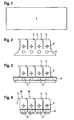
- lancet bodies 2 including lancet tips 3are cut out by means of laser cutting.
- the metal strip 1is a steel sheet whose thickness is 50 microns to 200 microns, preferably 60 microns to 100 microns.
- an Nd: YAG lasercan be used for laser cutting.
- the metal strip 1When cutting the metal strip 1, it is favorable to move the metal strip 1 relative to the laser beam, although it is of course also possible in principle to move the focus of the laser beam over the surface of the metal strip 1.
- the flame cuttingIn addition to the fusion cutting and Sublimierscene is particularly suitable for cutting the metal strip 1, the flame cutting. In flame cutting, oxygen is used as the cutting gas in order to increase by oxidation an eroding effect and thus the effectiveness of a laser beam of given power.
- the oxygenmay be blown through a nozzle to the focal point where the laser beam strikes the metal strip 1.
- process gases or gas mixturescan be used instead of oxygen. It is also possible to dispense with the use of process or cutting gases.
- a first steponly part of the contour of the lancet body 2 is initially cut out of the metal strip 1, so that the semifinished product strip shown in FIG. 2 results.
- the lancet body 2while two recesses 4, 5 are cut.
- the recess 4is a hole with a different contour from the circular shape, which is star-shaped in the illustrated embodiment.
- the recess 4forms a coupling element for coupling to a lancet drive of a puncturing device.
- a lancetcan be set in a rotary motion. Further details will be explained below with reference to FIGS 6 to 9.
- the recess 5 of the lancet body 2 shown in FIG. 2is a circular hole for the test field.
- a strip 6 with test chemicals for the examination of a body fluid sampleis applied in a further method step to the metal strip, preferably laminated, for example glued.
- FIG. 3shows the semifinished product shown in FIG. 2 with glued-on strip 6.
- the test chemicalsUpon contact with a body fluid sample, the test chemicals cause discoloration of the strip 6, the intensity of which depends on the concentration of the analyte to be determined, for example, glucose.
- Suitable test chemicals for photometric concentration determinationsare used in commercially available test elements which are used, for example, for measuring the glucose concentration, and therefore require no further explanation.
- To examine a body fluid samplethis is applied to the test field 5, so that the strip 6 is soaked.
- the strip 6can be cut in a preparatory step by means of the laser, which is also used to cut out the lancet body from the metal strip 1.
- the strip 6 with the test chemicalsfaces the laser beam during cutting, so that first the strip 6 is cut through during cutting and then the sheet metal 1 lying underneath in the direction of the beam.
- the strip 6 containing the test chemicalscontains polymer threads which can form, for example, a fleece, felt or fabric. At the edges of the strip 6, the polymer threads are fused by means of the laser and so prevents linting.
- the lancet tip 3is ground in a further step.
- the lancet tip 3is flattened.
- an edge 7 of the lancet tip 3 shown in FIG. 4can be formed as a blade.
- the lancet tip 3 and / or one of its edgescan be bevelled, with the term "obliquely" referring in this context to the plane of the lancet body 2.
- the finished lancets 10are sealed in chambers of a film package 11 shown in FIG.
- FIG. 5shows a lancet supply tape with a plurality of lancets 10, which are each sealed in chambers 12 of a film package 11, wherein the chambers 12 of the film package form a band.
- the film package 11may be formed, for example, as a blister package or two overlapping films or a longitudinally folded film strip may be welded along the welds 13 shown in FIG. 5 to provide an airtight seal to the chambers formed in this manner 12 to effect.
- Plastic filmsare particularly suitable for the foil packaging 11 of the lancets 10, in particular made of thermoplastics.
- the welds 13can be generated by means of the laser, which is also used for laser cutting of the metal strip 1. It is advantageous to move the laser beam with a suitable optics, such as a scanner optics along the welds 13 to be generated. In principle, however, it is also possible to replace the weld seams 13 shown in FIG. 5 by adhesive bonds.
- FIG. 6shows a schematic representation of an exemplary embodiment of a puncturing device 20 for producing a puncture wound into which a lancet supply strip according to FIG. 5 is inserted.
- the lancing device 20 illustrated in FIG. 6 for producing a puncture wound by means of a replaceable lancet 10comprises a lancet drive 21 for moving a lancet 10 inserted into the device 20 for a puncture, wherein the lancet drive 21 transmits a torque to an inserted lancet 10 for a puncture, so that it performs a puncturing movement in the form of a rotational movement.
- the lancet drive 21has a drive element in the form of a shaft 21, which has a shape matching the recess 4 forming the coupling element, in the illustrated embodiment, a star shape, and is inserted into the recess 4 for coupling.
- the drive element 21is sharpened, so that it can be easily stung through the film package 11 therethrough. In this way, the geometric axis of the rotational movement is perpendicular to the planar lancet body. 2
- a rotational movement of the drive element 21causes a rotational movement of the lancet 10 in the direction of the arrow A shown by a few degrees (preferably at least 15 °), so that the lancet tip 3 generates a puncture wound in a body part 23 attached to a device opening 22.
- the lancet tip 3performs a piercing movement in a rotational movement in a plane.
- the rotational movement of the lancet tip 3is arcuate, in particular circular.
- the coupling element 4 of the lancet 10is arranged such that the center of gravity of Lancet 10 is located in the coupling element 4.
- the coupling 4 forming the recess 4 of the lancet 10is therefore arranged so that it contains the physical center of gravity of the lancet 10, so that unbalance moments are minimized.
- the lancet tip 3cuts with a rotary motion the foil package 11, so that the lancet 10 is protected until it is used against harmful environmental influences. With this rotational movement for cutting the package 11, the lancet tip 3 first enters a preparation position (not shown). Typically, the lancet 10 remains in rest for a few seconds in the preparatory position before being accelerated, ie, further rotated, for the puncture motion. In this way, it is possible to avoid that the movement speed during the actual puncturing process is influenced by the packaging. In principle, however, it is also possible to open the foil packaging 11 only during the puncturing movement, ie to refrain from first turning the lancet into a preparatory position and thereby puncturing the packaging.
- a punctureis performed by means of a quick puncture and return movement.
- the direction of rotation of the lancet 10is thus reversed by means of the lancet drive 21 as soon as the lancet tip 3 has reached the predetermined penetration depth.
- a fast puncture and return motionminimizes the pain associated with creating a puncture.
- the lancet tip 3is rotated away from the device opening 22 and the opposite end of the lancet 10, on which the test field 5 is arranged, rotated out of the device opening 22, so that the lancet reaches a sample receiving position and a recovered from the puncture wound produced
- Body fluid samplecan be applied to the test field 5 for examination.
- the lancet 10is rotated in the illustrated embodiment of the lancet drive 21 by about 180 °, so that the test field 5 comes to a built-in the lancing device 20 measuring device 24, with a discoloration of the test field. 5 be recorded and evaluated photometrically can.
- a test field for electrochemical concentration determinationcan be used.
- an evaluation of the test field 6can also take place in the sample receiving position.
- the evaluation of a measurement in the sample receiving position by environmental influences, in particular scattered lightcan be made more difficult, however, there is no need for a further rotational movement of the lancet in which the test field 6 with an applied sample has to be moved through the foil packaging 11.
- unused lancets 10 of the lancet supply strip shown in FIG. 5are stored in a stack 25 and used lancets in a second stack 26.
- the two stacks 25, 26are arranged on the left and right of the device opening 22 inside the device.
- the film package 11 of the lancet supply strip shown in FIG. 5is folded along the weld seams 13 that run transversely to the direction of the band.
- An advantage of the illustrated lancing device 20 and the associated lancet storage tapeis that a lancet 10 can be rotated back into its original position after use, in which it is surrounded by the foil package 11, so that used lancets 10 are kept hygienically in the lancing device 20 can and when disposing of a spent lancet storage tape, the risk of injury from lancet tips 3 is reduced.
- the lancet 10can be moved by means of a single drive element to cut through the package 11, perform the puncture movement, take the measurement position and after the determination of the concentration again hygienically safe to be applied in the package 11.
- FIG. 7shows a further exemplary embodiment of a lancet 10 in a foil packaging 11.
- the embodiment shown in FIG. 7differs from the exemplary embodiment described above in that a lance 30, or more precisely, a lancet body 2 in addition to the lancet tip 3 for producing a puncture wound two mandrels 30, arranged to rupture the lancet 10 surrounding the foil packaging 11.
- the lancet 10is first rotated in a first direction of rotation, which is shown in Figure 7 by an arrow B.
- the lancet driveis preferably a spring drive whose spring is tensioned in the direction of the arrow B during the first rotational movement.
- the subsequent puncturing movement of the lancet tip 3can be performed unhindered without the lancet tip 3 would have to pierce the foil packaging.
- Thishas the advantage that the puncture movement can be performed faster and thus less pain.
- the lancet 10After puncture movement, the lancet 10 is rotated to the position shown in Figure 8, in which the test field 5 protrudes from the device opening 22, so that a body fluid sample can be applied to the test field 6. With a subsequent rotation, which is 180 ° in the exemplary embodiment of a puncturing device 20 shown in FIG. 6, the test field 5 can be screwed into the interior of the device 20 so that its discoloration can be evaluated by means of the measuring device 24.
- the position of the lancet 10 when measuring a discoloration of the test field 5is shown in FIG.
- the lancet 10After the measurement is the lancet 10 is rotated back into its starting position shown in Figure 7, in which it is stored until disposal.
- FIG. 10schematically shows a section of a metal strip 1, from which, as explained above, a lancet body 2 and a lancet tip 3 are cut out by means of laser cutting.
- first two boundary strips 31, 32are glued onto the metal strip 1.
- the boundary strips 31, 32are usually formed as narrow plastic strips which are arranged in parallel at a distance of for example 1 mm to 3 mm on the metal strip 1.
- FIG. 11shows a section of the metal strip 1 with attached boundary strips 31, 32.
- a paste or liquid with test chemicals for photometric concentration determinationis applied between the two boundary strips 31, 32.
- FIG. 12shows a plan view of a section of the metal strip 1 with adhered boundary strips 31, 32 and a gap filled with the test chemicals containing liquid or paste.
- FIG. 13shows a cross-sectional view of FIG. 12.
- FIG. 15shows, in a cross-sectional view, the conditions after the drying of the paste applied between the delimiting strips 31, 32.
- the representation shown in Figure 15is not to scale.
- the thickness of the boundary stripsis for example 20 microns, the thickness of the formed by drying strip 6 with test chemicals, for example, 10 microns and the thickness of the underlying metal strip 1, for example, 80 microns.
- FIG. 14shows a plan view of FIG. 15.
Landscapes
- Health & Medical Sciences (AREA)
- Life Sciences & Earth Sciences (AREA)
- Engineering & Computer Science (AREA)
- Surgery (AREA)
- Public Health (AREA)
- Physics & Mathematics (AREA)
- Animal Behavior & Ethology (AREA)
- General Health & Medical Sciences (AREA)
- Biomedical Technology (AREA)
- Heart & Thoracic Surgery (AREA)
- Medical Informatics (AREA)
- Molecular Biology (AREA)
- Veterinary Medicine (AREA)
- Biophysics (AREA)
- Pathology (AREA)
- Hematology (AREA)
- Manufacturing & Machinery (AREA)
- Nuclear Medicine, Radiotherapy & Molecular Imaging (AREA)
- Emergency Medicine (AREA)
- Optics & Photonics (AREA)
- Measurement Of The Respiration, Hearing Ability, Form, And Blood Characteristics Of Living Organisms (AREA)
- Adornments (AREA)
- Auxiliary Devices For And Details Of Packaging Control (AREA)
- Surgical Instruments (AREA)
Abstract
Description
Translated fromGermanDie Erfindung betrifft ein Verfahren zum Herstellen einer Lanzette, die einen Lanzettenkörper mit einer Lanzettenspitze umfasst, wobei der Lanzettenkörper mitsamt der Lanzettenspitze aus einem Metallband ausgeschnitten wird, sowie eine Lanzette mit einem Lanzettenkörper aus Metallblech, ein Lanzettenvorratsband und ein Stechgerät zum Erzeugen einer Einstichwunde mittels austauschbarer Lanzetten.The invention relates to a method for producing a lancet, which comprises a lancet body with a lancet tip, wherein the lancet body is cut out together with the lancet tip of a metal band, and a lancet with a lancet body made of sheet metal, a lancet supply tape and a puncturing device for producing a puncture wound by means of interchangeable lancets.
Stechgeräte und dazugehörende Lanzetten werden beispielsweise von Diabetikern benötigt, die mehrmals täglich ihren Blutzuckerspiegel kontrollieren müssen, indem in einem Körperteil, in der Regel einem Finger, eine kleine Einstichwunde erzeugt wird, um eine Körperflüssigkeitsprobe zu gewinnen, die mit einem Messgerät zur Bestimmung des Glukosegehalts untersucht werden kann. Um die Bestimmung des Glukosegehalts für Diabetiker möglichst einfach zu gestalten, sind beispielsweise aus der
Lanzetten werden als Verbrauchsgegenstände in großer Zahl benötigt und verursachen einen erheblichen Teil der mit der Behandlung von Diabetes verbundenen Kosten. Eine weit verbreitete Möglichkeit zur kostengünstigen Herstellung von Lanzetten besteht darin, aus einem Metallband einen Lanzettenkörper einschließlich einer Lanzettenspitze auszustanzen, wie es in der
Aufgabe der Erfindung ist es, einen Weg aufzuzeigen, wie bei der Diabetesbehandlung die mit Lanzetten verbundenen Kosten weiter gesenkt werden können.The object of the invention is to show a way, as in diabetes treatment, the costs associated with lancets can be further reduced.
Diese Aufgabe wird erfindungsgemäß durch ein Verfahren zum Herstellen einer Lanzette gelöst, die einen Lanzettenkörper mit einer Lanzettenspitze umfasst, wobei der Lanzettenkörper mitsamt der Lanzettenspitze mittels eines Lasers aus einem Metallband ausgeschnitten wird. Diese Aufgabe wird ferner gelöst durch eine Lanzette umfassend einen mittels Laserschneiden aus einem Metallblech ausgeschnittenen Lanzettenkörper mit einer Lanzettenspitze.This object is achieved by a method for producing a lancet comprising a lancet body with a lancet tip, wherein the lancet body is cut together with the lancet tip by means of a laser from a metal strip. This object is further achieved by a lancet comprising a lancet body cut out of a metal sheet by means of laser cutting with a lancet tip.
Bei einem mittels Laserschneiden aus einem Metallband ausgeschnittenen Metallkörper finden sich an den Schnitträndern charakteristische Ablagerungen von Metallen und Metalloxiden, die durch den Laserstrahl aufgeschmolzen bzw. erzeugt wurden. Ausgestanzte Metallteile haben besonders scharfkantige Ränder, so dass eine durch Laserschneiden hergestellte Lanzette eindeutig von einer ausgestanzten Lanzette unterschieden werden kann.In a metal body cut out of a metal strip by means of laser cutting, characteristic deposits of metals and metal oxides which have been melted or produced by the laser beam are found at the edges of the cut. Punched metal parts have particularly sharp-edged edges, so that a lancet produced by laser cutting can be clearly distinguished from a punched-out lancet.
Obwohl Lanzetten seit vielen Jahren in großen Stückzahlen hergestellt werden, können durch den erfindungsgemäßen Einsatz eines Lasers Einsparungspotentiale zur Kostensenkung ausgeschöpft werden. In anderen Bereichen der Technik ist das Laserschneiden für Kleinserien als Alternative zum Ausstanzen von Metallteilen gebräuchlich. Bei kleinen Stückzahlen ist das Laserschneiden in der Regel kostengünstiger als das Stanzen, da für die auszuschneidende Kontur kein individuell angefertigtes Stanzwerkzeug benötigt wird, dessen Kosten für eine wirtschaftliche Produktion auf große Stückzahlen umgelegt werden müssen. Es ist deshalb umso überraschender, dass sich trotz extrem hoher Stückzahlen Lanzetten mittels Laserschneiden kostengünstiger als durch Ausstanzen herstellen lassen.Although lancets have been produced in large quantities for many years, the use of a laser according to the invention can exploit savings potential for cost reduction. In other fields of technology, laser cutting is used for small batches as an alternative to punching metal parts. For small quantities, laser cutting is usually less expensive than punching, because no custom-made punching tool is required for the auszuschnende contour, the cost of an economic production must be transferred to large numbers. It is therefore all the more surprising that despite extremely high numbers of lancets can be produced by laser cutting more cost-effective than by punching.
Der Einsatz eines Lasers ermöglicht insbesondere bei der Herstellung von so genannten integrierten Lanzetten, die ein Testfeld zum Untersuchen einer durch eine Einstichwunde gewonnenen Körperflüssigkeitsprobe aufweisen, die Einsparung von Produktionskosten. Derartige Lanzetten mit einem metallischen Lanzettenkörper und einem Testfeld zu photometrischen oder elektrochemischen Konzentrationsbestimmung erfordern nach dem Stand der Technik eine Fülle von unterschiedlichen Fertigungstechnologien, um einerseits metallische Komponenten der Lanzette, das heißt den Lanzettenkörper und die Lanzettenspitze, und andererseits nichtmetallische Komponenten, insbesondere das Testfeld, zu bearbeiten. Diese unterschiedlichen Technologien müssen aufeinander abgestimmt werden so dass die Investitionskosten für eine Massenfertigung mit der Anzahl der eingesetzten Fertigungstechnologien stark anwachsen. Hinzu kommt, dass jeder Fertigungsschritt nur eine begrenzte Anlageneffizienz hat, so dass bei einer Fertigung, die mehrere Fertigungsschritte mit unterschiedlichen Technologien kombiniert, die Gefahr einer geringen Gesamtanlageneffizienz besteht.The use of a laser makes it possible to save on production costs, particularly in the manufacture of so-called integrated lancets, which have a test field for examining a body fluid sample obtained by a puncture wound. Such lancets with a metallic lancet body and a test field for photometric or electrochemical concentration determination require in the state of the art a wealth of different production technologies, on the one hand metallic components of the lancet, that is the lancet body and the lancet tip, and on the other hand non-metallic components, in particular the test field, to edit. These different technologies have to be coordinated so that the investment costs for mass production increase strongly with the number of production technologies used. In addition, each manufacturing step has a limited plant efficiency, so that in a manufacturing, which combines several manufacturing steps with different technologies, the risk of low overall system efficiency exists.
Im Gegensatz zu den im Stand der Technik gebräuchlichen Fertigungstechnologien wie Ätzen oder Stanzen, lässt sich ein Laser nicht nur zur Bearbeitung metallischer Lanzettenkomponenten sondern auch für nichtmetallische Lanzettenkomponenten, wie beispielsweise einem Polymerfadengewebe mit Testchemikalien für eine in die Lanzette integrierte Testeinrichtung in Form eines Testfelds, nutzen. Mittels eines Lasers lassen sich der Lanzettenkörper samt Lanzettenspitze aus Metallblech ausschneiden, ein Polymerfadengewebe zuschneiden und dessen Ränder verschmelzen sowie eine Lanzette in eine Folienverpackung einschweißen.In contrast to conventional fabrication technologies such as etching or punching, a laser can be used not only for machining metallic lancet components but also for non-metallic lancet components, such as a polymeric thread web with test chemicals for a lancet integrated test device in the form of a test field , By means of a laser, the lancet body, including the lancet tip, can be cut out of sheet metal, a polymer thread fabric can be cut, and its edges melted, and a lancet can be welded into a foil packaging.
Testfelder mit Testchemikalien, die durch eine Verfärbung die Konzentration eines Analyten, beispielsweise Glukose, anzeigen, sind sehr empfindlich. Lanzetten mit integrierten Testfeldern müssen deshalb bis zum Gebrauch trocken und vor Umwelteinflüssen geschützt gelagert werden. Dies lässt sich in vorteilhafter Weise dadurch realisieren, dass die Lanzetten einzeln in eine Folienverpackung aus Kunststoff eingeschweißt sind. Auch für diesen Herstellungsschritt ist ein Laser hervorragend geeignet.Test fields containing test chemicals that indicate the concentration of an analyte, such as glucose, through discoloration are very sensitive. Lancets with integrated test fields must therefore be stored dry and protected from environmental influences until use. This can be realized in an advantageous manner in that the lancets are individually welded into a plastic film package. Also for this manufacturing step, a laser is ideal.
Ein weiterer Aspekt der Erfindung, der auch eigenständige Bedeutung für auf andere Weise hergestellte Lanzetten haben kann, betrifft deshalb ein Lanzettenvorratsband, umfassend mehrere Lanzetten, die jeweils in Kammern einer Folienverpackung versiegelt sind, wobei die Kammern der Folienverpackung ein Band bilden. Ein derartiges Lanzettenvorratsband kann beispielsweise dadurch hergestellt werden, dass Lanzetten in einer Reihe auf einer Kunststofffolie angeordnet werden, anschließend mit einer zweiten Folie bedeckt werden und die aufeinander liegenden Folien rund um die Lanzetten jeweils miteinander verschweißt werden, so dass sich ein Band von luftdicht verschlossenen Kammern bildet.Another aspect of the invention, which may also have independent significance for otherwise prepared lancets, therefore relates to a lancet supply band comprising a plurality of lancets, each sealed in chambers of a foil package, the chambers of the foil package forming a band. Such a lancet supply tape can be produced, for example, by arranging lancets in a row on a plastic film, then covering them with a second film and then welding the superimposed films around the lancets together to form a band of hermetically sealed chambers forms.
Im Rahmen der Erfindung wurde festgestellt, dass sich flache, das heißt aus einem Metallband ausgeschnittene, Lanzetten aus einer Folienverpackung besonders leicht durch eine Drehbewegung entnehmen lassen. Anstelle der im Stand der Technik gebräuchlichen linearen Einstichbewegungen kann mit einer Lanzette auch durch eine Drehbewegung eine Einstichwunde zum Gewinnen einer Körperflüssigkeitsprobe erzeugt werden. Ein wichtiger Aspekt der Erfindung, der auch eigenständige Bedeutung haben kann, betrifft deshalb eine Lanzette mit einem Lanzettenkörper aus Metallblech, der zum Ankuppeln an einen Lanzettenantrieb eines Stechgeräts ein Kupplungselement aufweist, über das die Lanzette in eine Drehbewegung versetzbar ist. Die Erfindung betrifft ferner ein Stechgerät zum Erzeugen einer Einstichwunde mittels einer austauschbaren Lanzette umfassend einen Lanzettenantrieb zum Bewegen einer in das Gerät eingesetzten Lanzette für einen Einstich, dadurch gekennzeichnet, dass der Lanzettenantrieb für einen Einstich ein Drehmoment auf eine eingesetzte Lanzette überträgt, so dass diese eine Einstichbewegung in Form einer Drehbewegung ausführt. Es hat sicht gezeigt, dass es günstig ist, wenn die als Einstichbewegung ausgeführte bogenförmige Drehbewegung der Lanzettenspitze nicht mehr als 180°, bevorzugt nicht mehr als 90°, insbesondere nicht mehr als 45°, überstreicht.In the context of the invention it has been found that flat, that is cut out of a metal band, lancets can be removed from a foil packaging particularly easily by a rotational movement. Instead of the linear puncturing movements common in the state of the art, a puncture wound for obtaining a body fluid sample can also be generated by means of a rotary movement with a lancet. An important aspect of the invention, which may also have independent significance, therefore relates to a lancet with a lancet body made of sheet metal, which has a coupling element for coupling to a lancet drive of a lancing device, via which the lancet can be set in a rotational movement. The invention further relates to a puncturing device for generating a puncture wound by means of an exchangeable lancet comprising a lancet drive for moving a lancet inserted into the device for a puncture, characterized in that the lancet drive for a puncture a torque to an inserted Lancet transmits, so that it performs a puncture movement in the form of a rotary motion. It has been shown that it is favorable if the arcuate rotary movement of the lancet tip, which is embodied as a puncturing movement, does not cover more than 180 °, preferably not more than 90 °, in particular not more than 45 °.
Am einfachsten lässt sich das Kupplungselement als Ausnehmung in dem Lanzettenkörper ausbilden, die formschlüssig mit einem Lanzettenantrieb eines Stechgeräts kuppelbar ist, so dass ein Drehmoment von dem Lanzettenantrieb auf die Lanzette übertragen werden kann. Zum Kuppeln wird ein Antriebselement des Lanzettenantriebs, beispielsweise eine Welle mit einem zu der Ausnehmung passenden Querschnitt, in die Ausnehmung der Lanzette gesteckt, so dass sich eine Drehbewegung des Antriebselements auf die Lanzette überträgt. Prinzipiell ist hierfür jede von der Kreisform abweichende Kontur der Ausnehmung geeignet. Bevorzugt hat die Ausnehmung jedoch eine kantige, beispielsweise eine stern- oder vierkantförmige Kontur, da sich der Formschluss zwischen der Ausnehmung und dem Antriebselement des Lanzettenantriebs zum Austausch einer Lanzette in der Regel umso leichter lösen lässt, je deutlicher die Abweichung von der Kreisform ist.The simplest way to form the coupling element as a recess in the lancet body, which is positively coupled with a lancet drive of a lancing device, so that a torque can be transmitted from the lancet drive to the lancet. For coupling, a drive element of the lancet drive, for example a shaft with a cross section matching the recess, is inserted into the recess of the lancet, so that a rotational movement of the drive element is transmitted to the lancet. In principle, any contour of the recess deviating from the circular shape is suitable for this purpose. Preferably, however, the recess has an edged, for example, a star or square contour, since the positive connection between the recess and the drive element of the lancet drive for replacement of a lancet usually easier to solve, the clearer the deviation from the circular shape.
Das Wort "formschlüssig" bedeutet in diesem Zusammenhang, dass eine Kraftübertragung zum Erzeugen einer Drehbewegung rechtwinklig zu den aneinander anliegenden Flächen der Verbindungspartner erfolgt. Die betreffenden Flächen sind einerseits die Außenfläche eines Verbindungselements, beispielsweise einer Welle, die an der Innenseite der Ausnehmung des Lanzettenkörpers, in der Regel einem durchgehenden Loch, anliegt. Da der Lanzettenkörper naturgemäß flach ist, ist die Innenfläche der Ausnehmung notwendigerweise sehr klein und kann im Extremfall auch durch eine Kante oder Linie gebildet werden, gegen die das Antriebselement zur Übertragung eines Drehmoments drückt.The word "positive fit" in this context means that a power transmission for generating a rotational movement takes place at right angles to the abutting surfaces of the connection partners. On the one hand, the surfaces in question are the outer surface of a connecting element, for example a shaft, which bears against the inside of the recess of the lancet body, as a rule a through hole. Since the lancet body is naturally flat, the inner surface of the recess is necessarily very small and in extreme cases can also be formed by an edge or line against which the drive element presses to transmit a torque.
Die Vorteile einer Lanzette mit einem Kupplungselement, über das die Lanzette in eine Drehbewegung versetzbar ist, sowie eines dazugehörenden Stechgeräts, bei dem der Lanzettenantrieb für einen Einstich ein Drehmoment auf eine eingesetzte Lanzette überträgt, so dass diese eine Einstichbewegung in Form einer Drehbewegung ausführt, lassen sich auch mit Lanzetten nutzen, deren Lanzettenkörper einschließlich der Lanzettenspitze aus einem Metallband ausgestanzt oder auf andere Weise hergestellt wurde. Lanzetten mit einem Lanzettenkörper, der zum Ankuppeln an einen Lanzettenantrieb eines Stechgeräts ein Kupplungselement aufweist, über das die Lanzette in eine Drehbewegung versetzbar ist, und das dazugehörende Stechgerät sind deshalb ebenso wie das angesprochene Lanzettenvorratsband mit einem Band von Kammern einer Folienverpackung, in denen sich jeweils eine Lanzette befindet, Aspekte der Erfindung mit eigenständiger Bedeutung.The advantages of a lancet with a coupling element, via which the lancet is set into a rotational movement, and an associated lancing device, in which the lancet drive for a puncture a Torque is transmitted to an inserted lancet so that it performs a piercing motion in the form of a rotational movement, can also be used with lancets whose lancet body was punched out of a metal strip including the lancet tip or otherwise produced. Lancets with a lancet body, which has a coupling element for coupling to a lancet drive of a lancing device, via which the lancet is set into a rotary motion, and the associated lancing device are therefore just like the mentioned lancet supply tape with a band of chambers of a foil packaging, in each case a lancet, aspects of the invention with independent meaning.
Weitere Einzelheiten und Vorteile der Erfindung werden im Folgenden anhand von Ausführungsbeispielen unter Bezugnahme auf die beigefügten Zeichnungen erläutert. Gleiche oder entsprechende Teile sind dabei mit übereinstimmenden Bezugszeichen gekennzeichnet. Im Rahmen der Ausführungsbeispiele offenbarte Merkmale können einzeln oder in Kombination zum Gegenstand von Ansprüchen gemacht werden. Es zeigen:
- Fig. 1
- ein Stahlblech, aus dem mittels eines Lasers ein Lanzettenkörper einschließlich einer Lanzettenspitze ausgeschnitten wird;
- Fig. 2
- ein aus dem Metallband ausgeschnittenes Halbzeug, mit teilweise aus dem Band ausgeschnitten Lanzettenkörper;
- Fig. 3
- das in
Figur 2 dargestellte Halbzeug und einen daran befestigten Streifen mit Testchemikalien; - Fig. 4
- ein Ausführungsbeispiel fertiger Lanzetten;
- Fig. 5
- ein Ausführungsbeispiel eines Lanzettenvorratsbands mit mehreren Lanzetten gemäß dem in
Figur 4 dargestellten Ausführungsbeispiel, die jeweils in Kammern einer Folienverpackung versiegelt sind; - Fig. 6
- ein Ausführungsbeispiel eines Stechgeräts mit einem eingelegten Lanzettenvorratsband gemäß
Figur 5; - Fig. 7
- ein weiteres Ausführungsbeispiel einer erfindungsgemäßen Lanzette in einer Folienverpackung;
- Fig. 8
- das in
Figur 7 dargestellte Ausführungsbeispiel nach Herausdrehen aus der Folienverpackung für eine Probenaufnahme; - Fig. 9
- das in den
Figuren 7 und 8 dargestellte Ausführungsbeispiel nach Gebrauch in einer Messposition; - Fig. 10
- ein Ausschnitt eines
Metallbands 1 mit Begrenzungsstreifen zwischen die zum Ausbilden eines Testfelds eine Flüssigkeit mit Testchemikalien aufgebracht wird; - Fig. 11
- eine Querschnittsansicht zu
Figur 10; - Fig. 12
- das Metallband gemäß
Figur 10 mit aufgebrachter Flüssigkeit; - Fig. 13
- eine
Querschnittsansicht zu Figur 12; - Fig. 14
- das Metallband nach Eintrocknen der Flüssigkeit; und
- Fig. 15
- eine Querschnittsansicht zu Figur 14.
- Fig. 1
- a steel sheet from which a lancet body including a lancet tip is cut by means of a laser;
- Fig. 2
- a semifinished product cut out of the metal band, with lancet body partially cut out of the band;
- Fig. 3
- the semifinished product shown in Figure 2 and an attached strip with test chemicals;
- Fig. 4
- an embodiment of finished lancets;
- Fig. 5
- an embodiment of a lancet storage tape with a plurality of lancets according to the embodiment shown in Figure 4, which are each sealed in chambers of a foil packaging;
- Fig. 6
- an embodiment of a puncturing device with an inserted lancet supply tape according to Figure 5;
- Fig. 7
- a further embodiment of a lancet according to the invention in a foil package;
- Fig. 8
- the embodiment shown in Figure 7 after unscrewing from the foil packaging for a sample holder;
- Fig. 9
- the embodiment shown in Figures 7 and 8 after use in a measuring position;
- Fig. 10
- a section of a
metal strip 1 with boundary strips between which a test chemical is applied with a test chemical to form a test field; - Fig. 11
- a cross-sectional view of Figure 10;
- Fig. 12
- the metal strip according to Figure 10 with applied liquid;
- Fig. 13
- a cross-sectional view of Figure 12;
- Fig. 14
- the metal strip after the liquid has dried; and
- Fig. 15
- a cross-sectional view of Figure 14.
Im Folgenden wird anhand der Figuren 1 bis 4 ein Ausführungsbeispiel eines Verfahrens zur Herstellung eines Ausführungsbeispiels einer Flachlanzette erläutert. Aus dem in Figur 1 dargestellten Metallband 1 werden mittels Laserschneiden Lanzettenkörper 2 einschließlich Lanzettenspitzen 3 ausgeschnitten. Bei den dargestellten Ausführungsbeispielen ist das Metallband 1 ein Stahlblech, dessen Stärke 50 µm bis 200 µm, bevorzugt 60 µm bis 100 µm, beträgt. Für das Laserschneiden kann beispielsweise ein Nd:YAG-Laser verwendet werden.An exemplary embodiment of a method for producing an exemplary embodiment of a flat lancet will be explained below with reference to FIGS. From the
Beim Schneiden des Metallbands 1 ist es günstig, das Metallband 1 relativ zu dem Laserstrahl zu bewegen, obwohl es prinzipiell selbstverständlich auch möglich ist, den Fokus des Laserstrahls über die Oberfläche des Metallbands 1 zu bewegen. Neben den Schmelzschneiden und dem Sublimierschneiden ist zum Schneiden des Metallbandes 1 insbesondere das Brennschneiden geeignet. Beim Brennschneiden wird als Schneidgas Sauerstoff eingesetzt, um durch Oxidation eine erodierende Wirkung und damit die Effektivität eines Laserstrahls gegebener Leistung zu erhöhen.When cutting the
Der Sauerstoff kann durch eine Düse zu dem Brennpunkt, in dem der Laserstrahl auf das Metallband 1 trifft, geblasen werden. Anstelle von Sauerstoff können prinzipiell auch andere Prozessgase oder Gasmischungen verwendet werden. Möglich ist es auch, auf den Einsatz von Prozess- oder Schneidgasen zu verzichten.The oxygen may be blown through a nozzle to the focal point where the laser beam strikes the
In einem ersten Arbeitsschritt wird aus dem Metallband 1 zunächst nur ein Teil der Kontur der Lanzettenkörper 2 ausgeschnitten, so dass sich das in Figur 2 dargestellte Halbzeugband ergibt. In den Lanzettenkörper 2 werden dabei zwei Ausnehmungen 4, 5 geschnitten. Bei der Ausnehmung 4 handelt es sich um ein Loch mit einer von der Kreisform abweichenden Kontur, die bei dem dargestellten Ausführungsbeispiel sternförmig ist. Die Ausnehmung 4 bildet ein Kupplungselement zum Ankuppeln an einen Lanzettenantrieb eines Stechgeräts. Über das Kupplungselement 4 kann eine Lanzette in eine Drehbewegung versetzt werden. Nähere Details hierzu werden im Folgenden anhand der Figuren 6 bis 9 erläutert.In a first step, only part of the contour of the
Bei der Ausnehmung 5 des in Figur 2 gezeigten Lanzettenkörpers 2 handelt es sich um ein kreisförmiges Loch für das Testfeld. Zur Ausbildung des Testfelds wird in einem weiteren Verfahrensschritt auf das Metallband ein Streifen 6 mit Testchemikalien zur Untersuchung einer Körperflüssigkeitsprobe aufgebracht, bevorzugt auflaminiert, beispielsweise aufgeklebt. In Figur 3 ist das in Figur 2 gezeigte Halbzeug mit aufgeklebtem Streifen 6 dargestellt. Bei Kontakt mit einer Körperflüssigkeitsprobe bewirken die Testchemikalien eine Verfärbung des Streifens 6, deren Intensität von der Konzentration des zu bestimmenden Analyten, beispielsweise Glukose, abhängt. Geeignete Testchemikalien zur photometrischen Konzentrationsbestimmungen werden bei handelsüblichen Testelementen, die beispielsweise zur Messung der Glukosekonzentration verwendet werden, eingesetzt und bedürfen daher keiner näheren Erläuterung. Zur Untersuchung einer Körperflüssigkeitsprobe wird diese auf das Testfeld 5 aufgebracht, so dass der Streifen 6 getränkt wird. Der Streifen 6 kann in einem vorbereitenden Verfahrensschritt mittels des Lasers, der auch zum Ausschneiden des Lanzettenkörpers aus dem Metallband 1 verwendet wird, zugeschnitten werden.The
Nach dem Aufkleben des Streifens 6 mit den Testchemikalien wird in einem weiteren Verfahrensschritt die restliche Kontur des Lanzettenkörpers 2 ausgeschnitten, so dass sich die in Figur 4 gezeigten Lanzetten 10 ergeben. Für die Schnittqualität ist es dabei günstig, wenn der Streifen 6 mit den Testchemikalien beim Schneiden dem Laserstrahl zugewandt ist, so dass beim Schneiden zuerst der Streifen 6 und danach das in Strahlrichtung darunter liegende Metallblech 1 durchgeschnitten werden.After sticking the
Der Streifen 6 mit den Testchemikalien enthält Polymerfäden, die beispielsweise ein Vlies, Filz oder Gewebe bilden können. An den Rändern des Streifens 6 werden die Polymerfäden mittels des Lasers verschmolzen und so eine Fusselbildung verhindert.The
Bevorzugt wird die Lanzettenspitze 3 in einem weiteren Arbeitsschritt angeschliffen. Dabei wird die Lanzettenspitze 3 abgeflacht. Auf diese Weise kann eine in Fig. 4 dargestellte Kante 7 der Lanzettenspitze 3 als Klinge ausgebildet werden. Beispielsweise kann die Lanzettenspitze 3 und/oder eine Ihrer Kanten angeschrägt werden, wobei sich die Angabe "schräg" in diesem Zusammenhang auf die Ebene des Lanzettenkörpers 2 bezieht. Durch das Anschleifen der Lanzettenspitze 3 lässt sich erreichen, dass die Lanzettenspitze 3 bei einem Einstich leichter in die Hautoberfläche eines Benutzers eindringt und somit der mit einem Einstich verbundene Schmerz reduziert wird.Preferably, the
In einem weiteren Schritt werden die fertigen Lanzetten 10 in Kammern einer in Figur 5 dargestellten Folienverpackung 11 versiegelt. Figur 5 zeigt einen Lanzettenvorratsband mit mehreren Lanzetten 10, die jeweils in Kammern 12 einer Folienverpackung 11 versiegelt sind, wobei die Kammern 12 der Folienverpackung ein Band bilden. Für das in Figur 5 dargestellte Lanzettenvorratsband kann die Folienverpackung 11 beispielsweise als Blisterverpackung ausgebildet werden oder es können zwei aufeinander liegende Folien oder ein in Längsrichtung gefalteter Folienstreifen entlang der in Figur 5 dargestellten Schweißnähte 13 verschweißt werden, um eine luftdichte Versiegelung der auf diese Weise gebildeten Kammern 12 zu bewirken. Besonders gut für die Folienverpackung 11 der Lanzetten 10 sind Kunststofffolien geeignet, insbesondere aus Thermoplasten. Die Schweißnähte 13 können mittels des Lasers erzeugt werden, der auch zum Laserschneiden des Metallbandes 1 eingesetzt wird. Dabei ist es günstig, den Laserstrahl mit einer geeigneten Optik, beispielsweise einer Scanner-Optik, entlang der zu erzeugenden Schweißnähte 13 zu bewegen. Prinzipiell ist es jedoch auch möglich, die in Figur 5 dargestellten Schweißnähte 13 durch Klebeverbindungen zu ersetzen.In a further step, the
Figur 6 zeigt eine schematische Darstellung eines Ausführungsbeispiels eines Stechgeräts 20 zum Erzeugen einer Einstichwunde, in das ein Lanzettenvorratsband gemäß Figur 5 eingesetzt ist. Das in Figur 6 dargestellte Stechgerät 20 zum Erzeugen einer Einstichwunde mittels einer austauschbaren Lanzette 10 umfasst einen Lanzettenantrieb 21 zum Bewegen einer in das Gerät 20 eingesetzten Lanzette 10 für einen Einstich, wobei der Lanzettenantrieb 21 für einen Einstich ein Drehmoment auf eine eingesetzte Lanzette 10 überträgt, so dass diese eine Einstichbewegung in Form einer Drehbewegung ausführt. Der Lanzettenantrieb 21 hat ein Antriebselement in Form einer Welle 21, die eine zu der das Kupplungselement 4 bildenden Ausnehmung passende Form, bei dem dargestellten Ausführungsbeispiel eine Sternform, aufweist und zum Ankuppeln in die Ausnehmung 4 hineingesteckt wird. Das Antriebselement 21 ist zugespitzt, so dass es leicht durch die Folienverpackung 11 hindurch gestochen werden kann. Auf diese Weise läuft die geometrische Achse der Drehbewegung senkrecht zu dem ebenen Lanzettenkörper 2.FIG. 6 shows a schematic representation of an exemplary embodiment of a
Eine Drehbewegung des Antriebselements 21 bewirkt eine Drehbewegung der Lanzette 10 in Richtung des dargestellten Pfeils A um einige Grad (bevorzugt mindestens 15°), so dass die Lanzettenspitze 3 in einem an eine Geräteöffnung 22 angelegten Körperteil 23 eine Einstichwunde erzeugt. Die Lanzettenspitze 3 führt bei einer Einstichbewegung eine Drehbewegung in einer Ebene durch. Die Drehbewegung der Lanzettenspitze 3 ist bogenförmig, insbesondere kreisförmig. Hierfür ist es günstig, wenn das Kupplungselement 4 der Lanzette 10, wie bei dem dargestellten Ausführungsbeispiel, derart angeordnet ist, dass der Schwerpunkt der Lanzette 10 in dem Kupplungselement 4 liegt. Die das Kupplungselement bildende Ausnehmung 4 der Lanzette 10 ist deshalb derart angeordnet, dass sie den physikalischen Schwerpunkt der Lanzette 10 enthält, so dass Unwuchtmomente minimiert werden. Die Lanzettenspitze 3 zerschneidet mit eine Drehbewegung die Folienverpackung 11, so dass die Lanzette 10 bis zu ihrer Verwendung vor schädlichen Umwelteinflüssen geschützt ist. Mit dieser Drehbewegung zum Zerschneiden der Verpackung 11 gelangt die Lanzettenspitze 3 zunächst in eine Vorbereitungsposition (nicht dargestellt). Typischerweise bleibt die Lanzette 10 einige Sekunden in der Vorbereitungsposition in Ruhe, bevor sie für die Einstichbewegung beschleunigt wird, d.h. weitergedreht wird. Auf diese Weise lässt sich vermeiden, dass die Bewegungsgeschwindigkeit bei dem eigentlichen Einstichvorgang durch die Verpackung beeinflusst wird. Prinzipiell ist es aber auch möglich, die Folienverpackung 11 erst bei der Einstichbewegung zu öffnen, also darauf zu verzichten, die Lanzette zunächst in eine Vorbereitungsposition zu drehen und schon dabei die Verpackung zu durchstoßen.A rotational movement of the
Ein Einstich wird mittels einer schnellen Einstich- und Rückführbewegung ausgeführt. Die Drehrichtung der Lanzette 10 wird mittels des Lanzettenantriebs 21 also umgekehrt, sobald die Lanzettenspitze 3 die vorgegebene Einstichtiefe erreicht hat. Durch eine schnelle Einstich- und Rückführbewegung lässt sich der mit dem Erzeugen eines Einstichs verbundene Schmerz minimieren.A puncture is performed by means of a quick puncture and return movement. The direction of rotation of the
Nach erfolgtem Einstich wird die Lanzettenspitze 3 von der Geräteöffnung 22 weggedreht und das entgegen gesetzte Ende der Lanzette 10, an dem das Testfeld 5 angeordnet ist, aus der Geräteöffnung 22 herausgedreht, so dass die Lanzette in eine Probenaufnahmeposition gelangt und eine aus der erzeugten Einstichwunde gewonnene Körperflüssigkeitsprobe zur Untersuchung auf das Testfeld 5 aufgebracht werden kann. Nach dem Aufbringen einer Körperflüssigkeitsprobe auf das Testfeld 5 wird die Lanzette 10 bei dem dargestellten Ausführungsbeispiel von dem Lanzettenantrieb 21 um etwa 180° gedreht, so dass das Testfeld 5 zu einer in das Stechgerät 20 integrierten Messeinrichtung 24 gelangt, mit der eine Verfärbung des Testfelds 5 photometrisch erfasst und ausgewertet werden kann. Als Alternative zu einem Testfeld mit Testchemikalien, deren Verfärbung photometrisch ausgewertet wird, kann ein Testfeld zur elektrochemischen Konzentrationsbestimmung verwendet werden.After the puncture, the
Bei einer anderen Anordnung der Messeinrichtung 24 kann eine Auswertung des Testfeldes 6 auch in der Probenaufnahmeposition erfolgen. Zwar kann die Auswertung einer Messung in der Probenaufaufnahmeposition durch Umwelteinflüsse, insbesondere Streulicht, erschwert werden, jedoch entfällt die Notwendigkeit einer weiteren Drehbewegung der Lanzette, bei der das Testfeld 6 mit einer aufgebrachten Probe durch die Folienverpackung 11 hindurchbewegt werden muss. Bei einer Messung in der Probenaufnahmeposition ist deshalb die Gefahr einer Verschmutzung des Geräteinneren durch Probenflüssigkeit in vorteilhafter Weise reduziert.In another arrangement of the measuring
Bei dem dargestellten Stechgerät 20 werden unbenutzte Lanzetten 10 des in Figur 5 dargestellten Lanzettenvorratsbands in einem Stapel 25 und benutzte Lanzetten in einem zweiten Stapel 26 gelagert. Die beiden Stapel 25, 26 sind links und rechts von der Geräteöffnung 22 im Geräteinneren angeordnet. Dabei wird die Folienverpackung 11 des in Figur 5 dargestellten Lanzettenvorratsbands jeweils entlang der quer zur Bandrichtung verlaufenen Schweißnähte 13 gefaltet. Ein Vorteil des dargestellten Stechgeräts 20 und des dazugehörenden Lanzettenvorratsbands besteht darin, dass eine Lanzette 10 nach Gebrauch wieder in ihre Ausgangsposition zurück gedreht werden kann, in der sie von der Folienverpackung 11 umgeben ist, so dass gebrauchte Lanzetten 10 hygienisch in dem Stechgerät 20 aufbewahrt werden können und bei einer Entsorgung eines aufgebrauchten Lanzettenvorratsbands die Gefahr von Verletzungen durch Lanzettenspitzen 3 reduziert ist. Bei dem dargestellten Ausführungsbeispiel kann die Lanzette 10 mittels eines einzigen Antriebselements bewegt werden, um die Verpackung 11 zu durchtrennen, die Einstichbewegung auszuführen, die Messposition einzunehmen und nach erfolgter Konzentrationsbestimmung wieder hygienisch sicher in der Verpackung 11 angelegt zu werden.In the illustrated lancing
Figur 7 zeigt ein weiteres Ausführungsbeispiel einer Lanzette 10 in einer Folienverpackung 11. Das in Figur 7 dargestellte Ausführungsbeispiel unterschiedet sich von dem im vorhergehenden beschriebenen Ausführungsbeispiel dadurch, dass an dem Lanzettenkörper 2 zusätzlich zu der Lanzettenspitze 3 zum Erzeugen einer Einstichwunde ein Dorn 30, genauer gesagt zwei Dorne 30, zum Aufreißen der die Lanzette 10 umgebenden Folienverpackung 11 angeordnet ist. Zum Aufreißen der Folienverpackung 11 wird die Lanzette 10 zunächst in einer ersten Drehrichtung gedreht, die in Figur 7 durch einen Pfeil B dargestellt ist. Bei dieser ersten Drehbewegung werden die Seiten der Folienverpackung 11 von den beiden Dornen 30 aufgeschlitzt. Anschließend wird mit der Lanzette 10 eine Einstichwunde mit einer Drehbewegung in entgegengesetzter Drehrichtung erzeugt. Bei dem Lanzettenantrieb handelt es sich bevorzugt um einen Federantrieb, dessen Feder bei der ersten Drehbewegung in Richtung des Pfeils B gespannt wird.FIG. 7 shows a further exemplary embodiment of a
Indem die Folienverpackung 11 mittels der Dorne 30 aufgeschnitten wird, kann die darauf folgende Einstichbewegung der Lanzettenspitze 3 ungehindert durchgeführt werden, ohne dass die Lanzettenspitze 3 die Folienverpackung durchstoßen müsste. Dies hat den Vorteil, dass die Einstichbewegung schneller und damit schmerzärmer durchgeführt werden kann. Ferner ist eine Beeinträchtigung der Schärfe der Lanzettenspitze 3, die beim Aufreißen der Folienverpackung 11 auftreten könnte, ausgeschlossen.By the
Nach erfolgter Einstichbewegung wird die Lanzette 10 in die in Figur 8 dargestellte Position gedreht, in der das Testfeld 5 aus der Geräteöffnung 22 herausragt, so dass eine Körperflüssigkeitsprobe auf das Testfeld 6 aufgebracht werden kann. Mit einer anschließenden Drehung, die bei dem in Figur 6 dargestellten Ausführungsbeispiel eines Stechgeräts 20 180° beträgt, kann das Testfeld 5 in das Innere des Geräts 20 hineingedreht, so dass dessen Verfärbung mittels der Messeinrichtung 24 ausgewertet werden kann. Für das in Figur 6 dargestellte Ausführungsbeispiel eines Stechgeräts 20 ist die Position der Lanzette 10 beim Messen einer Verfärbung des Testfeldes 5 in Figur 9 dargestellt. Nach erfolgter Messung wird die Lanzette 10 wieder in ihre in Figur 7 dargestellte Ausgangsposition zurückgedreht, in der sie bis zur Entsorgung gelagert wird. Wie bereits erwähnt, besteht jedoch auch die Möglichkeit, die Messung in der in Fig. 8 dargestellten Probenaufnahmeposition durchzuführen, so dass die in Fig. 9 dargestellte Position bei einem Ausführungsbeispiel, das in Bezug auf die Anordnung der Messeinrichtung 24 anders als das in Fig. 6 dargestellte Ausführungsbeispiel konstruiert ist, nicht eingenommen werden muss.After puncture movement, the
Anstatt ein Streifen 6 mit Testchemikalien zur Ausbildung des Testfelds 5 auf einen Lanzettenkörper 2 oder ein Metallband 1 aufzukleben, kann man auch eine Paste oder Flüssigkeit mit Testchemikalien auf das Metallband 1 oder den Lanzettenkörper 2, der aus dem Metallband 1 ausgeschnitten wird, aufbringen, so dass diese Paste nach Trocknung das Testfeld 5 bildet. Diese alternative Vorgehensweise wird im Folgenden anhand der Figuren 10 bis 15 erläutert.Instead of sticking a
Figur 10 zeigt schematisch einen Ausschnitt eines Metallbands 1, aus dem wie im Vorhergehenden erläutert, mittels Laserschneiden ein Lanzettenkörper 2 und Lanzettenspitze 3 ausgeschnitten wird. Zur Ausbildung des Testfeldes 5 der auszuschneidenden Lanzetten 10 werden zunächst zwei Begrenzungsstreifen 31, 32 auf das Metallband 1 geklebt. Die Begrenzungsstreifen 31, 32 sind üblicherweise als schmale Kunststoffstreifen ausgebildet, die parallel in einem Abstand von beispielsweise 1 mm bis 3 mm auf den Metallband 1 angeordnet werden. Figur 11 zeigt einen Ausschnitt des Metallbands 1 mit aufgeklebten Begrenzungsstreifen 31, 32. In einem weiteren Verfahrensschritt wird zwischen die beiden Begrenzungsstreifen 31, 32 eine Paste oder Flüssigkeit mit Testchemikalien zur photometrischen Konzentrationsbestimmung aufgebracht. In Figur 12 ist ein Ausschnitt des Metallbands 1 mit aufgeklebten Begrenzungsstreifen 31, 32 und einen mit der Testchemikalien enthaltenden Flüssigkeit oder Paste verfüllten Zwischenraum in einer Draufsicht dargestellt. Figur 13 zeigt eine Querschnittsansicht zu Figur 12.FIG. 10 schematically shows a section of a
Anschließend wird die aufgetragene Flüssigkeit oder Paste eingetrocknet, so dass sich zwischen den Begrenzungsstreifen 31, 32 ein Streifen 6 bildet, der das Testfeld 5 enthält. Die Dicke des nach Trocknung zwischen den Begrenzungsstreifen 31, 32 verbleibenden Streifens 6 hängt von dem Feststoffgehalt der aufgetragenen Paste oder Flüssigkeit ab. Figur 15 zeigt in einer Querschnittsansicht die Verhältnisse nach dem Eintrocknen der zwischen den Begrenzungsstreifen 31, 32 aufgebrachten Paste. Die in Figur 15 gezeigte Darstellung ist nicht maßstäblich. Die Dicke der Begrenzungsstreifen beträgt beispielsweise 20 µm, die Dicke des durch Eintrocknung gebildeten Streifens 6 mit Testchemikalien beispielsweise 10 µm und die Dicke des darunter liegenden Metallbands 1 beispielsweise 80 µm. Figur 14 zeigt eine Draufsicht zu Figur 15.Subsequently, the applied liquid or paste is dried, so that between the boundary strips 31, 32 forms a
Bei Lanzetten mit einem Testfeld 5, das gemäß dem anhand der Figuren 10 bis 15 beschriebenen Verfahren hergestellt wurde, ist eine Ausnehmung 5, wie sie in Figur 2 dargestellt ist, naturgemäß nicht vorhanden. Die Messeinrichtung 24 zur photometrischen Auswertung einer Farbänderung des Testfelds 5 befindet sich deshalb bei der Auswertung auf derselben Seite des Metallbandes 1 wie das Testfeld 5. Wird dagegen ein Streifen 6 gemäß der anhand der Figuren 1 bis 4 beschriebene Verfahren über eine Ausnehmung 5 in einem Lanzettenkörper 2 geklebt, kann die photometrische Messapparatur wegen der Ausnehmung in dem Lanzettenkörper 2 auf der anderen Seite angeordnet werden, so dass sich der Lanzettenkörper 2 zwischen dem Teststreifen 6 und der Messapparatur befindet.In lancets with a
- 11
- Metallbandmetal band
- 22
- LanzettenkörperLancet body
- 33
- LanzettenspitzeLancet tip
- 44
- Kupplungselementcoupling member
- 55
- Testfeldtest field
- 66
- Streifen mit TestchemikalienStrip with test chemicals
- 77
- LanzettenspitzenkanteLancet tip edge
- 1010
- Lanzettelancet
- 1111
- Folienverpackungfilm packaging
- 1212
- Kammer der FolienverpackungChamber of foil packaging
- 1313
- Schweißnähtewelds
- 2020
- Stechgerätlancing device
- 2121
- LanzettenantriebLancet drive
- 2222
- Geräteöffnungopening devices
- 2323
- Körperteilbody part
- 2424
- Messeinrichtungmeasuring device
- 2525
- Stapel unbenutzter LanzettenStack of unused lancets
- 2626
- Stapel benutzter LanzettenStack of used lancets
- 3030
- Aufreißdornripper shank
- 3131
- Begrenzungsstreifenlimiting strip
- 3232
- Begrenzungsstreifenlimiting strip
- AA
- Pfeilrichtung für Drehbewegung bei EinstichArrow direction for rotary movement at puncture
- BB
- Pfeilrichtung für Drehbewegung zum Aufreißen der FolienverpackungArrow direction for rotary movement for tearing the foil packaging
Claims (16)
Translated fromGermaneinen Lanzettenantrieb (21) zum Bewegen einer in das Stechgerät (20) eingesetzten Lanzette (10) für einen Einstich,dadurch gekennzeichnet, dass der Lanzettenantrieb (21) für einen Einstich ein Drehmoment auf eine eingesetzte Lanzette (10) überträgt, so dass die eingesetzte Lanzette (10) eine Einstichbewegung in Form einer Drehbewegung ausführt.Lancing device for generating a puncture wound by means of an exchangeable lancet (10) according to claims 9 to 14, comprising
a lancet drive (21) for moving a lancing device (10) for a puncture inserted into the lancing device (20),characterized in that the lancet drive (21) transmits a torque to an inserted lancet (10) for a puncture, so that the inserted lancet (10) Lancet (10) performs a puncture movement in the form of a rotational movement.
Priority Applications (9)
| Application Number | Priority Date | Filing Date | Title |
|---|---|---|---|
| EP06014792AEP1878386A1 (en) | 2006-07-15 | 2006-07-15 | Process to produce lancet; lancet, lancet band and device for pricking the skin |
| EP07012764AEP1878387B1 (en) | 2006-07-15 | 2007-06-29 | Lancet, lancet feeder belt and pricking device for creating a puncture wound |
| DE502007005730TDE502007005730D1 (en) | 2006-07-15 | 2007-06-29 | Lancet, lancet supply tape and lancing device for creating a puncture wound |
| AT07012764TATE489037T1 (en) | 2006-07-15 | 2007-06-29 | LANCET, LANCET SUPPLY TAPE AND Pricking device for creating a puncture wound |
| JP2007180830AJP2008043741A (en) | 2006-07-15 | 2007-07-10 | Lancet, lancet supply ribbon and lancing device for scratching |
| CA002593349ACA2593349A1 (en) | 2006-07-15 | 2007-07-11 | Lancet, lancet supply ribbon, and puncturing device for generating a puncturing wound |
| CN200710136464ACN100591272C (en) | 2006-07-15 | 2007-07-16 | Lancet, lancet supply belt and lancing device for producing a puncture wound |
| US11/778,362US20100023045A1 (en) | 2006-07-15 | 2007-07-16 | Lancet, Lancet Supply Ribbon, and Puncturing Device for Generating a Puncturing Wound |
| HK08107413.6AHK1117720B (en) | 2006-07-15 | 2008-07-07 | Lancet, lancet supply ribbon, and puncturing device for generating a puncturing wound |
Applications Claiming Priority (1)
| Application Number | Priority Date | Filing Date | Title |
|---|---|---|---|
| EP06014792AEP1878386A1 (en) | 2006-07-15 | 2006-07-15 | Process to produce lancet; lancet, lancet band and device for pricking the skin |
Publications (1)
| Publication Number | Publication Date |
|---|---|
| EP1878386A1true EP1878386A1 (en) | 2008-01-16 |
Family
ID=37560790
Family Applications (1)
| Application Number | Title | Priority Date | Filing Date |
|---|---|---|---|
| EP06014792AWithdrawnEP1878386A1 (en) | 2006-07-15 | 2006-07-15 | Process to produce lancet; lancet, lancet band and device for pricking the skin |
Country Status (7)
| Country | Link |
|---|---|
| US (1) | US20100023045A1 (en) |
| EP (1) | EP1878386A1 (en) |
| JP (1) | JP2008043741A (en) |
| CN (1) | CN100591272C (en) |
| AT (1) | ATE489037T1 (en) |
| CA (1) | CA2593349A1 (en) |
| DE (1) | DE502007005730D1 (en) |
Cited By (1)
| Publication number | Priority date | Publication date | Assignee | Title |
|---|---|---|---|---|
| EP2229886A1 (en)* | 2009-03-17 | 2010-09-22 | Roche Diagnostics GmbH | Lance with plastic attachment element |
Families Citing this family (14)
| Publication number | Priority date | Publication date | Assignee | Title |
|---|---|---|---|---|
| US20060281187A1 (en) | 2005-06-13 | 2006-12-14 | Rosedale Medical, Inc. | Analyte detection devices and methods with hematocrit/volume correction and feedback control |
| US8801631B2 (en) | 2005-09-30 | 2014-08-12 | Intuity Medical, Inc. | Devices and methods for facilitating fluid transport |
| EP3984454A1 (en) | 2008-06-06 | 2022-04-20 | Intuity Medical, Inc. | Medical diagnostic devices and methods |
| WO2009148624A1 (en) | 2008-06-06 | 2009-12-10 | Intuity Medical, Inc. | Detection meter and mode of operation |
| PL2218399T3 (en)* | 2009-02-17 | 2014-03-31 | Hoffmann La Roche | Reuse protection for lancet system |
| EP2506768B1 (en) | 2009-11-30 | 2016-07-06 | Intuity Medical, Inc. | Calibration material delivery devices and methods |
| US8647357B2 (en)* | 2011-02-05 | 2014-02-11 | Birch Narrows Development Llc | Lancet device with flexible cover |
| US9782114B2 (en) | 2011-08-03 | 2017-10-10 | Intuity Medical, Inc. | Devices and methods for body fluid sampling and analysis |
| US20130211289A1 (en) | 2012-01-25 | 2013-08-15 | Tasso, Inc. | Handheld Device for Drawing, Collecting, and Analyzing Bodily Fluid |
| US9237866B2 (en) | 2013-04-29 | 2016-01-19 | Birch Narrows Development, LLC | Blood glucose management |
| CN106999120B (en) | 2014-08-01 | 2021-05-14 | 塔索公司 | Devices, systems, and methods for gravity-enhanced microfluidic collection, handling, and delivery of liquids |
| CA3009328C (en) | 2015-12-21 | 2024-03-05 | Tasso, Inc. | Devices, systems and methods for actuation and retraction in fluid collection |
| JP7460607B2 (en) | 2018-09-14 | 2024-04-02 | タッソ インコーポレイテッド | Body fluid collection devices and related methods |
| AU2022227019A1 (en) | 2021-02-26 | 2023-08-31 | Tasso, Inc. | Bodily fluid collection devices and related methods |
Citations (13)
| Publication number | Priority date | Publication date | Assignee | Title |
|---|---|---|---|---|
| EP0217246A2 (en)* | 1985-09-30 | 1987-04-08 | Miles Inc. | Test device, method of manufacturing same and method of determining a component in a sample |
| US5314441A (en)* | 1992-10-16 | 1994-05-24 | International Technidyne Corporation | Disposable slicing lancet assembly |
| US5571132A (en)* | 1995-06-06 | 1996-11-05 | International Technidyne Corporation | Self activated finger lancet |
| WO1998014125A1 (en)* | 1996-10-02 | 1998-04-09 | Specialized Health Products, Inc. | Lancet apparatus and methods |
| US5951582A (en)* | 1998-05-22 | 1999-09-14 | Specialized Health Products, Inc. | Lancet apparatus and methods |
| WO2002050534A1 (en)* | 2000-12-19 | 2002-06-27 | Inverness Medical Limited | Device for measuring blood coagulation and method thereof |
| EP1284121A2 (en)* | 2001-08-06 | 2003-02-19 | Lifescan, Inc. | Physiological sample collection devices and methods of using the same |
| EP1346686A2 (en) | 2002-03-05 | 2003-09-24 | Bayer Healthcare, LLC | Fluid collection apparatus having an integrated lancet and reaction area |
| WO2004086970A1 (en) | 2003-04-04 | 2004-10-14 | Roche Diagnostics Gmbh | Method for producing a puncturing and measuring device |
| US20050011858A1 (en)* | 2003-07-16 | 2005-01-20 | Industrial Technology Research Institute | Method for fabricating a hollow micro-needle array |
| WO2005084530A2 (en) | 2004-03-06 | 2005-09-15 | F. Hoffmann-La Roche Ag | Body fluid sampling device |
| WO2006082106A1 (en)* | 2005-02-07 | 2006-08-10 | Roche Diagnostics Gmbh | Lancet protective cap |
| EP1714613A1 (en)* | 2005-04-22 | 2006-10-25 | F. Hoffmann-La Roche Ag | Analyzing means |
Family Cites Families (16)
| Publication number | Priority date | Publication date | Assignee | Title |
|---|---|---|---|---|
| US2823677A (en)* | 1955-01-17 | 1958-02-18 | Becton Dickinson Co | Lancet |
| GB1599654A (en)* | 1977-08-05 | 1981-10-07 | Holman R R | Automatic lancet |
| US5476474A (en)* | 1994-07-27 | 1995-12-19 | Ryder International Corporation | Rotary lancet |
| US6221089B1 (en)* | 1997-07-07 | 2001-04-24 | International Technidyne Corporation | Skin incision device with compression spring assembly |
| US6036924A (en)* | 1997-12-04 | 2000-03-14 | Hewlett-Packard Company | Cassette of lancet cartridges for sampling blood |
| US6783502B2 (en)* | 2001-04-26 | 2004-08-31 | Phoenix Bioscience | Integrated lancing and analytic device |
| US6988996B2 (en)* | 2001-06-08 | 2006-01-24 | Roche Diagnostics Operatons, Inc. | Test media cassette for bodily fluid testing device |
| DE10142232B4 (en)* | 2001-08-29 | 2021-04-29 | Roche Diabetes Care Gmbh | Process for the production of an analytical aid with a lancet and test element |
| US7060192B2 (en)* | 2002-05-09 | 2006-06-13 | Lifescan, Inc. | Methods of fabricating physiological sample collection devices |
| US7481777B2 (en)* | 2006-01-05 | 2009-01-27 | Roche Diagnostics Operations, Inc. | Lancet integrated test element tape dispenser |
| DE10302501A1 (en)* | 2003-01-23 | 2004-08-05 | Roche Diagnostics Gmbh | Device and method for absorbing a body fluid for analysis purposes |
| AU2004203280A1 (en)* | 2003-07-28 | 2005-02-17 | Bayer Healthcare Llc | Swing Lance with Integrated Sensor |
| EP1737345A1 (en)* | 2004-04-15 | 2007-01-03 | Roche Diagnostics GmbH | Integrated spot monitoring device with fluid sensor |
| US8591436B2 (en)* | 2004-04-30 | 2013-11-26 | Roche Diagnostics Operations, Inc. | Lancets for bodily fluid sampling supplied on a tape |
| US7695442B2 (en)* | 2005-04-12 | 2010-04-13 | Roche Diagnostics Operations, Inc. | Integrated lancing test strip with retractable lancet |
| EP1698279A1 (en)* | 2005-03-04 | 2006-09-06 | Disetronic Licensing AG | Sequential insertion of main-penetrators |
- 2006
- 2006-07-15EPEP06014792Apatent/EP1878386A1/ennot_activeWithdrawn
- 2007
- 2007-06-29ATAT07012764Tpatent/ATE489037T1/enactive
- 2007-06-29DEDE502007005730Tpatent/DE502007005730D1/enactiveActive
- 2007-07-10JPJP2007180830Apatent/JP2008043741A/enactivePending
- 2007-07-11CACA002593349Apatent/CA2593349A1/ennot_activeAbandoned
- 2007-07-16USUS11/778,362patent/US20100023045A1/ennot_activeAbandoned
- 2007-07-16CNCN200710136464Apatent/CN100591272C/ennot_activeExpired - Fee Related
Patent Citations (13)
| Publication number | Priority date | Publication date | Assignee | Title |
|---|---|---|---|---|
| EP0217246A2 (en)* | 1985-09-30 | 1987-04-08 | Miles Inc. | Test device, method of manufacturing same and method of determining a component in a sample |
| US5314441A (en)* | 1992-10-16 | 1994-05-24 | International Technidyne Corporation | Disposable slicing lancet assembly |
| US5571132A (en)* | 1995-06-06 | 1996-11-05 | International Technidyne Corporation | Self activated finger lancet |
| WO1998014125A1 (en)* | 1996-10-02 | 1998-04-09 | Specialized Health Products, Inc. | Lancet apparatus and methods |
| US5951582A (en)* | 1998-05-22 | 1999-09-14 | Specialized Health Products, Inc. | Lancet apparatus and methods |
| WO2002050534A1 (en)* | 2000-12-19 | 2002-06-27 | Inverness Medical Limited | Device for measuring blood coagulation and method thereof |
| EP1284121A2 (en)* | 2001-08-06 | 2003-02-19 | Lifescan, Inc. | Physiological sample collection devices and methods of using the same |
| EP1346686A2 (en) | 2002-03-05 | 2003-09-24 | Bayer Healthcare, LLC | Fluid collection apparatus having an integrated lancet and reaction area |
| WO2004086970A1 (en) | 2003-04-04 | 2004-10-14 | Roche Diagnostics Gmbh | Method for producing a puncturing and measuring device |
| US20050011858A1 (en)* | 2003-07-16 | 2005-01-20 | Industrial Technology Research Institute | Method for fabricating a hollow micro-needle array |
| WO2005084530A2 (en) | 2004-03-06 | 2005-09-15 | F. Hoffmann-La Roche Ag | Body fluid sampling device |
| WO2006082106A1 (en)* | 2005-02-07 | 2006-08-10 | Roche Diagnostics Gmbh | Lancet protective cap |
| EP1714613A1 (en)* | 2005-04-22 | 2006-10-25 | F. Hoffmann-La Roche Ag | Analyzing means |
Cited By (2)
| Publication number | Priority date | Publication date | Assignee | Title |
|---|---|---|---|---|
| EP2229886A1 (en)* | 2009-03-17 | 2010-09-22 | Roche Diagnostics GmbH | Lance with plastic attachment element |
| WO2010105733A1 (en)* | 2009-03-17 | 2010-09-23 | Roche Diagnostics Gmbh | Lancet having a piercing element made of plastic |
Also Published As
| Publication number | Publication date |
|---|---|
| CA2593349A1 (en) | 2008-01-15 |
| CN100591272C (en) | 2010-02-24 |
| US20100023045A1 (en) | 2010-01-28 |
| ATE489037T1 (en) | 2010-12-15 |
| HK1117720A1 (en) | 2009-01-23 |
| CN101103922A (en) | 2008-01-16 |
| JP2008043741A (en) | 2008-02-28 |
| DE502007005730D1 (en) | 2011-01-05 |
Similar Documents
| Publication | Publication Date | Title |
|---|---|---|
| EP1878386A1 (en) | Process to produce lancet; lancet, lancet band and device for pricking the skin | |
| DE10315544B4 (en) | Method for producing a piercing and measuring device and device | |
| EP2050392B1 (en) | Lancet wheel | |
| EP1834696B1 (en) | Method for producing a multi-layer analysis element | |
| DE4228993C2 (en) | Surgical laser device | |
| EP2205432B1 (en) | Method for producing strip goods having diagnostic aids | |
| WO2006100265A1 (en) | Analytical aid with a lancet and a testing element | |
| EP1818014A1 (en) | Test element with elastically supported lancet | |
| EP2923192B1 (en) | Test piece for determining the cutting performance of a knife | |
| WO2011006913A1 (en) | Optimized lancet strip | |
| WO2008083844A1 (en) | Pricking device | |
| WO2012041346A1 (en) | Method for testing a laser device | |
| EP2113197A1 (en) | Lancet wheel and method for manufacturing a lancet wheel | |
| DE4406818C1 (en) | Method and device for welding at least metal parts | |
| EP2408370B1 (en) | Test device in particular for blood sugar tests | |
| EP1878387B1 (en) | Lancet, lancet feeder belt and pricking device for creating a puncture wound | |
| DE202015009238U1 (en) | Device for laser-assisted cutting of a workpiece | |
| EP1911394B1 (en) | Lancet with capillar channel | |
| EP2011630A1 (en) | Method for manufacturing an analytical element | |
| DE10129618A1 (en) | Air bag cover sheet has line of weakness made up of non-intersecting, curved slots which also have curved cross-section, seen through thickness of sheet | |
| DE102005002014B4 (en) | Method and device for introducing an opening into a workpiece | |
| DE2909349C3 (en) | Test device for carrying out skin tests | |
| EP2658450B1 (en) | Container made from a composite of aluminium foil and polymer and used for analytical aids, and method for producing said container | |
| EP2446268B1 (en) | Spreading layer and method for producing an analysis element spreading layer | |
| EP2378970B1 (en) | Lancet having capillary channel and sterile protection and method for producing such a lancet |
Legal Events
| Date | Code | Title | Description |
|---|---|---|---|
| PUAI | Public reference made under article 153(3) epc to a published international application that has entered the european phase | Free format text:ORIGINAL CODE: 0009012 | |
| AK | Designated contracting states | Kind code of ref document:A1 Designated state(s):AT BE BG CH CY CZ DE DK EE ES FI FR GB GR HU IE IS IT LI LT LU LV MC NL PL PT RO SE SI SK TR | |
| AX | Request for extension of the european patent | Extension state:AL BA HR MK YU | |
| AKX | Designation fees paid | ||
| STAA | Information on the status of an ep patent application or granted ep patent | Free format text:STATUS: THE APPLICATION IS DEEMED TO BE WITHDRAWN | |
| 18D | Application deemed to be withdrawn | Effective date:20080717 | |
| REG | Reference to a national code | Ref country code:DE Ref legal event code:8566 |