EP1876828B1 - Method and apparatus for configuring parameter values for cameras - Google Patents
Method and apparatus for configuring parameter values for camerasDownload PDFInfo
- Publication number
- EP1876828B1 EP1876828B1EP06116500.7AEP06116500AEP1876828B1EP 1876828 B1EP1876828 B1EP 1876828B1EP 06116500 AEP06116500 AEP 06116500AEP 1876828 B1EP1876828 B1EP 1876828B1
- Authority
- EP
- European Patent Office
- Prior art keywords
- cameras
- image data
- parameter values
- subset
- camera
- Prior art date
- Legal status (The legal status is an assumption and is not a legal conclusion. Google has not performed a legal analysis and makes no representation as to the accuracy of the status listed.)
- Active
Links
Images


Classifications
- G—PHYSICS
- G08—SIGNALLING
- G08B—SIGNALLING OR CALLING SYSTEMS; ORDER TELEGRAPHS; ALARM SYSTEMS
- G08B13/00—Burglar, theft or intruder alarms
- G08B13/18—Actuation by interference with heat, light, or radiation of shorter wavelength; Actuation by intruding sources of heat, light, or radiation of shorter wavelength
- G08B13/189—Actuation by interference with heat, light, or radiation of shorter wavelength; Actuation by intruding sources of heat, light, or radiation of shorter wavelength using passive radiation detection systems
- G08B13/194—Actuation by interference with heat, light, or radiation of shorter wavelength; Actuation by intruding sources of heat, light, or radiation of shorter wavelength using passive radiation detection systems using image scanning and comparing systems
- G08B13/196—Actuation by interference with heat, light, or radiation of shorter wavelength; Actuation by intruding sources of heat, light, or radiation of shorter wavelength using passive radiation detection systems using image scanning and comparing systems using television cameras
- G08B13/19665—Details related to the storage of video surveillance data
- G08B13/19671—Addition of non-video data, i.e. metadata, to video stream
- G—PHYSICS
- G08—SIGNALLING
- G08B—SIGNALLING OR CALLING SYSTEMS; ORDER TELEGRAPHS; ALARM SYSTEMS
- G08B13/00—Burglar, theft or intruder alarms
- G08B13/18—Actuation by interference with heat, light, or radiation of shorter wavelength; Actuation by intruding sources of heat, light, or radiation of shorter wavelength
- G08B13/189—Actuation by interference with heat, light, or radiation of shorter wavelength; Actuation by intruding sources of heat, light, or radiation of shorter wavelength using passive radiation detection systems
- G08B13/194—Actuation by interference with heat, light, or radiation of shorter wavelength; Actuation by intruding sources of heat, light, or radiation of shorter wavelength using passive radiation detection systems using image scanning and comparing systems
- G08B13/196—Actuation by interference with heat, light, or radiation of shorter wavelength; Actuation by intruding sources of heat, light, or radiation of shorter wavelength using passive radiation detection systems using image scanning and comparing systems using television cameras
- G08B13/19665—Details related to the storage of video surveillance data
- G08B13/19676—Temporary storage, e.g. cyclic memory, buffer storage on pre-alarm
- G—PHYSICS
- G08—SIGNALLING
- G08B—SIGNALLING OR CALLING SYSTEMS; ORDER TELEGRAPHS; ALARM SYSTEMS
- G08B13/00—Burglar, theft or intruder alarms
- G08B13/18—Actuation by interference with heat, light, or radiation of shorter wavelength; Actuation by intruding sources of heat, light, or radiation of shorter wavelength
- G08B13/189—Actuation by interference with heat, light, or radiation of shorter wavelength; Actuation by intruding sources of heat, light, or radiation of shorter wavelength using passive radiation detection systems
- G08B13/194—Actuation by interference with heat, light, or radiation of shorter wavelength; Actuation by intruding sources of heat, light, or radiation of shorter wavelength using passive radiation detection systems using image scanning and comparing systems
- G08B13/196—Actuation by interference with heat, light, or radiation of shorter wavelength; Actuation by intruding sources of heat, light, or radiation of shorter wavelength using passive radiation detection systems using image scanning and comparing systems using television cameras
- G08B13/19678—User interface
- G08B13/19691—Signalling events for better perception by user, e.g. indicating alarms by making display brighter, adding text, creating a sound
- G08B13/19693—Signalling events for better perception by user, e.g. indicating alarms by making display brighter, adding text, creating a sound using multiple video sources viewed on a single or compound screen
- H—ELECTRICITY
- H04—ELECTRIC COMMUNICATION TECHNIQUE
- H04N—PICTORIAL COMMUNICATION, e.g. TELEVISION
- H04N23/00—Cameras or camera modules comprising electronic image sensors; Control thereof
- H04N23/60—Control of cameras or camera modules
- H04N23/62—Control of parameters via user interfaces
- H—ELECTRICITY
- H04—ELECTRIC COMMUNICATION TECHNIQUE
- H04N—PICTORIAL COMMUNICATION, e.g. TELEVISION
- H04N23/00—Cameras or camera modules comprising electronic image sensors; Control thereof
- H04N23/60—Control of cameras or camera modules
- H04N23/63—Control of cameras or camera modules by using electronic viewfinders
- H04N23/631—Graphical user interfaces [GUI] specially adapted for controlling image capture or setting capture parameters
- H04N23/632—Graphical user interfaces [GUI] specially adapted for controlling image capture or setting capture parameters for displaying or modifying preview images prior to image capturing, e.g. variety of image resolutions or capturing parameters
- H—ELECTRICITY
- H04—ELECTRIC COMMUNICATION TECHNIQUE
- H04N—PICTORIAL COMMUNICATION, e.g. TELEVISION
- H04N23/00—Cameras or camera modules comprising electronic image sensors; Control thereof
- H04N23/60—Control of cameras or camera modules
- H04N23/66—Remote control of cameras or camera parts, e.g. by remote control devices
- H04N23/661—Transmitting camera control signals through networks, e.g. control via the Internet
- H—ELECTRICITY
- H04—ELECTRIC COMMUNICATION TECHNIQUE
- H04N—PICTORIAL COMMUNICATION, e.g. TELEVISION
- H04N23/00—Cameras or camera modules comprising electronic image sensors; Control thereof
- H04N23/70—Circuitry for compensating brightness variation in the scene
- H—ELECTRICITY
- H04—ELECTRIC COMMUNICATION TECHNIQUE
- H04N—PICTORIAL COMMUNICATION, e.g. TELEVISION
- H04N23/00—Cameras or camera modules comprising electronic image sensors; Control thereof
- H04N23/80—Camera processing pipelines; Components thereof
- H04N23/84—Camera processing pipelines; Components thereof for processing colour signals
- H04N23/88—Camera processing pipelines; Components thereof for processing colour signals for colour balance, e.g. white-balance circuits or colour temperature control
- H—ELECTRICITY
- H04—ELECTRIC COMMUNICATION TECHNIQUE
- H04N—PICTORIAL COMMUNICATION, e.g. TELEVISION
- H04N23/00—Cameras or camera modules comprising electronic image sensors; Control thereof
- H04N23/90—Arrangement of cameras or camera modules, e.g. multiple cameras in TV studios or sports stadiums
- H—ELECTRICITY
- H04—ELECTRIC COMMUNICATION TECHNIQUE
- H04N—PICTORIAL COMMUNICATION, e.g. TELEVISION
- H04N7/00—Television systems
- H04N7/18—Closed-circuit television [CCTV] systems, i.e. systems in which the video signal is not broadcast
- H04N7/181—Closed-circuit television [CCTV] systems, i.e. systems in which the video signal is not broadcast for receiving images from a plurality of remote sources
- G—PHYSICS
- G08—SIGNALLING
- G08B—SIGNALLING OR CALLING SYSTEMS; ORDER TELEGRAPHS; ALARM SYSTEMS
- G08B13/00—Burglar, theft or intruder alarms
- G08B13/18—Actuation by interference with heat, light, or radiation of shorter wavelength; Actuation by intruding sources of heat, light, or radiation of shorter wavelength
- G08B13/189—Actuation by interference with heat, light, or radiation of shorter wavelength; Actuation by intruding sources of heat, light, or radiation of shorter wavelength using passive radiation detection systems
- G08B13/194—Actuation by interference with heat, light, or radiation of shorter wavelength; Actuation by intruding sources of heat, light, or radiation of shorter wavelength using passive radiation detection systems using image scanning and comparing systems
- G08B13/196—Actuation by interference with heat, light, or radiation of shorter wavelength; Actuation by intruding sources of heat, light, or radiation of shorter wavelength using passive radiation detection systems using image scanning and comparing systems using television cameras
- G08B13/19634—Electrical details of the system, e.g. component blocks for carrying out specific functions
- G08B13/19636—Electrical details of the system, e.g. component blocks for carrying out specific functions pertaining to the camera
- G—PHYSICS
- G08—SIGNALLING
- G08B—SIGNALLING OR CALLING SYSTEMS; ORDER TELEGRAPHS; ALARM SYSTEMS
- G08B13/00—Burglar, theft or intruder alarms
- G08B13/18—Actuation by interference with heat, light, or radiation of shorter wavelength; Actuation by intruding sources of heat, light, or radiation of shorter wavelength
- G08B13/189—Actuation by interference with heat, light, or radiation of shorter wavelength; Actuation by intruding sources of heat, light, or radiation of shorter wavelength using passive radiation detection systems
- G08B13/194—Actuation by interference with heat, light, or radiation of shorter wavelength; Actuation by intruding sources of heat, light, or radiation of shorter wavelength using passive radiation detection systems using image scanning and comparing systems
- G08B13/196—Actuation by interference with heat, light, or radiation of shorter wavelength; Actuation by intruding sources of heat, light, or radiation of shorter wavelength using passive radiation detection systems using image scanning and comparing systems using television cameras
- G08B13/19665—Details related to the storage of video surveillance data
- G08B13/19667—Details realated to data compression, encryption or encoding, e.g. resolution modes for reducing data volume to lower transmission bandwidth or memory requirements
Definitions
- the present inventiongenerally relates to a method for configuring parameter values for a plurality of cameras, an apparatus comprising a processing device, a display adapted for showing image data, an input device, a memory adapted for holding a number of parameter values and for buffering image data, and a data communication interface adapted for communication through a data communications network with a plurality of cameras, a method for parameter value configuration of a camera, a camera having a processor device, a memory adapted for holding a number of parameter values, and a data communication interface adapted for communication through a data communications network, said camera stores parameter values which control the appearance of image data captured by said camera, a system for configuration of at least one parameter value in a plurality of cameras, comprising a camera and an apparatus, and a computer program.
- a modern security systemoften comprises a number of surveillance cameras.
- the surveillance camerasgive the security personnel a possibility to monitor a large,area, such as several floors in an office building.
- the appearance of the images from the number of camerasshould preferably be substantially similar with respect to brightness, sharpness, etc., since this makes the work of the operator less tiresome. More particularly, for a human eye, it is less tiresome analysing a number of images having similar apperance, than analysing a number of images with dissimilar appearance.
- the camerasWhen having a number of cameras, the cameras are most often placed at different places having different light conditions, which makes predetermined settings a non-optimal alternative. Further, the number of cameras may be different types of cameras with, for example, different types of image sensors, which even further make predetermined settings a non-optimal alternative.
- US 2003/0234866A1describes a practical real-time calibration of digital omnidirectional cameras in the areas of de-vignetting, brightness, contrast and white balance control. Novel solutions for the colour calibration of an omnidirectional camera rig, and an efficient method for devignetting images are also presented. Additionally, a context-specific method of stitching images together into a panorama or a mosaic is provided.
- WO 03/041411describes a multiple camera video system and methods for operating such a system.
- the systemmay include a plurality of cameras located around a stadium, athletic playing field or other location.
- the camerasare remotely controlled in a master-slave configuration.
- a camera operator at a master pan headselects one of the plurality of cameras as the current master camera and utilizes the master pan head to adjust the telemetry and zoom of the master camera to follow the target object.
- the telemetry and zoom parameters of the master cameraare then used to calculate corresponding telemetry, zoom and/or other parameters for each of the plurality of slave cameras.
- the multiple camera video systemalso includes methods for calibrating the system.
- WO 2006/041991discloses a video monitoring system which includes a video monitor configured to receive a video image from a video source such as a video camera, decompress the video image, and display the video image on a display screen according to a display format.
- the video monitormay be used to adjust one or more video parameters of the video image.
- the video monitormay further be configured to transmit the video image to a remote video device such as a remote video monitor or video recorder.
- an objective of the inventionis to solve or at least reduce the problems discussed above.
- an objectiveis to provide a method for configuring parameter values for a plurality of cameras, wherein an image feedback is provided after a reconfiguration of the parameter values.
- the plurality of camerasmay be all the cameras connected to a certain data communications network, but may also be a subset of cameras connected to the data communications network.
- Image data generated by the camerasmay be analog or digital, but preferably digital. Further, the image data may be still pictures, as well as video sequences. In one embodiment, the plurality of cameras generate video sequences normally, but still pictures as image feedback.
- a first aspect of the inventionis a method for configuring parameter values for a plurality of cameras, comprising acquiring image data from said plurality of cameras, said cameras store parameter values which control the appearance of image data captured by said cameras, buffering said image data from said plurality of cameras, displaying said buffered image data from said plurality of cameras, changing at least one parameter value for a first subset of said plurality of cameras, transmitting said at least one changed parameter value to said first subset of cameras to allow update of said at least one parameter value in each camera in said first subset, acquiring changed image data from a second subset of said plurality of cameras comprising at least the cameras of the first subset, replacing said buffered image data for said second subset of cameras with said changed image data for said second subset of cameras, and displaying said buffered image data for said plurality of cameras.
- An advantage with this first aspectis that an image feedback is given after changing the parameter values. In this way the user of an apparatus, configured to perform the steps according to the method of the first aspect, will easily see if the change of parameter values produced the desired result or not.
- the first subset of the methodmay be a part of the second subset.
- the first subsetmay be equal to the second subset.
- the second subsetmay be equal to the plurality of cameras.
- the changingmay involve receiving a user input from a user, and changing said at least one parameter value in accordance with said user input.
- An advantage of thisis that the user of the apparatus, performing the steps of the method according to the first aspect, may determine for himself in which way the parameter values is to be changed.
- the changingmay involve determining reference image data, calculating a correction value based on said reference image data, and changing said at least one parameter value in accordance with said correction value.
- the step of acquiring image data according to the first aspect of the inventionmay involve transmitting an image data request to said plurality of cameras.
- the method according to the first aspectmay further involve retrieving at least one parameter value from a predetermined set of parameter values.
- An advantage of thisis that a number of sets of predetermined parameter values for different environments may be provided to the user of the apparatus, performing the steps according to the method of the first aspect, wherein each such set of predetermined parameter values will function as a selectable template. In this way a first approximation of suitable parameter values may be easily and quickly done by the user of the apparatus by selecting the desired set of predetermined parameter values.
- the set of predetermined parameter valuesmay be selected from a group consisting of, but not limited to: a set of predetermined parameter values adapted for outdoor conditions, a set of predetermined parameter values adapted for indoor conditions, a set of predetermined parameter values adapted for fluorescent lighting conditions, a set of predetermined parameter values adapted for incandescent light conditions and a set of predetermined parameter values adapted for infrared light conditions.
- the step of retreivingmay further involve receiving a user input from a user, and retrieving said set of predetermined parameter values in accordance with said user input.
- the at least one parameter valuemay be selected from a group consisting of, but not limited to: a white balance value, a contrast value, a rotation value, a compression value, a sharpness value and a colour balance value.
- the parameter valuesmay be acquired together with said image data.from said plurality of cameras in said acquiring of image data and are displayed in said displaying of image data together with said image data.
- acquiring of said image data, buffering of said image data, displaying of said image data, changing of at least one parameter value for said first subset, transmitting of said at least one parameter value, acquiring of changed image data from said second subset, replacing of said buffered image data for said second subset, and displaying of said buffered image datamay be repeated iteratively until a user acceptance signal is received from a user.
- a second aspect of the inventionis an apparatus comprising a processing device, a display adapted for showing image data, :an input device, a memory adapted for holding a number of parameter values and for buffering image data, and a data communication interface adapted for communication through a data communications network with a plurality of cameras, wherein the processing device being adapted to acquire image data from said plurality of cameras, buffer said image data from said plurality of cameras in said memory, display said buffered image data from said plurality of cameras on said display, change at least one parameter value for a first subset of said plurality of cameras based upon an actuation of said input device, transmit said at least one parameter value to said first subset of cameras through said data communications network, to allow update of said at least one parameter value in each camera in said first subset, acquire changed image data from a second subset of said plurality of cameras through said data communications network, replace said buffered image data for said second subset of cameras with said changed image data for said second subset of cameras in said memory, and display said buffered image
- the apparatus according to the second aspectmay comprise a personal computer (PC).
- PCpersonal computer
- An advantage of thisis that any PC connected to a LAN (Local Area Network) to which a plurality of cameras is connected may be used as the apparatus according to the second aspect of the invention.
- LANLocal Area Network
- the apparatus according to the second aspectmay alternatively comprise a mobile terminal.
- the apparatus according to the second aspect of the inventionmay be adapted to perform the method according to the first aspect of the invention.
- a third aspect of the inventionis a method for parameter value configuration of a camera coupled to an apparatus through a data communications network, said camera stores parameter values which control the appearance of image data captured by said camera, whereby the steps, in said camera, of receiving an image data request from said apparatus, generating image data, using said parameter values, upon receiving said image data request, transmitting said image data to said apparatus, receiving a parameter value change request from said apparatus, changing at least one parameter value among said parameter values held in said camera based upon said parameter value change request, generating, using said parameter values as changed, changed image data, and transmitting said changed image data to said apparatus through said data communications network.
- a fourth aspect of the inventionis a camera having a processing device, a memory adapted for holding a number a parameter values, and a data communication interface adapted for communication through a data communications network, said camera stores parameter values which control the appearance of image data captured by said camera, whereby the processing device being adapted to receive an image data request from an apparatus through said data communications network, generate image data, using said parameter values, upon receiving said received image data request, transmit said image data to said apparatus through said data communications network, receive a parameter value change request from said apparatus through said data communications network, change at least one parameter value among said parameter values held in said memory in accordance with said parameter value change request, generate, using said parameter values as changed, changed image data, with said parameter values being changed, upon said parameter value change request, and transmit said changed image data to said apparatus through said data communications network.
- a fifth aspect of the inventionis a system for configuration of at least one parameter value in a plurality of cameras, comprising a data communications network, an apparatus according to the fourth aspect, connected to said data communications network, and a plurality of cameras configured for communication with said apparatus through said data communications network.
- a sixth aspect of the inventionis a computer program, comprising computer program code for performing the steps of the method according to the first aspect.
- the third to sixth aspects of the inventionmay have substantially the same or corresponding features, whenever applicable, as the first and second aspects.
- a general surveillance camera systemA general surveillance camera system
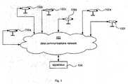
- Fig 1illustrates a general surveillance camera system with a plurality of cameras 100a-100f.
- Each camerais connected to a data communications network 102, such as a TCP/IP-based Local Area Network (LAN) or a TCP/IP-based Wireless Local Area Network (WLAN).
- An apparatus 104 for receiving and presenting image data from the cameras 100a-100fis also connected to the data communications network.
- LANLocal Area Network
- WLANWireless Local Area Network
- the apparatus 104can also be utilised for configuring the parameter values for each camera 100a-100f. This may, for instance, be to set the sharpness value for each of the camera to an appropriate value.
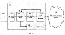
- Fig 2illustrates one of the cameras 100a-100f connected to the data communications network 102, shown in fig 1 in more detail.
- the camera 100comprises a lens 200, an image sensor 202, a processing device 204, a memory 206, a compression engine 208 and a data communication interface 210.
- the lens 200comprises optics adapted to focus incoming light onto the image sensor. Further, a number of associated devices for controlling the incoming light may be associated to the lens 200, such as a shutter for adjusting the amount of light and an exposure time control device for controlling the exposure time of the camera. Hereinafter, when referring to the lens 200 the associated devices should be included as well.
- the processing device 204can be one or several processors adapted to process the image data generated by the image sensor 202. Such processing can be motion detection, adding a time stamp to the present image data, and changing the parameter values of the image sensor 202.
- the processing devicecan, for instance, be an ETRAX 100LX 32-bit ASIC which is made commercially available by AXIS Communications AB.
- the memory 206is utilised by the processing device 204, e.g. for storing parameter values.
- the memorycan be divided into a RAM memory and a Flash memory.
- the image datais transferred to the compression engine 208.
- the compression enginethe image data is compressed in accordance with a compression format, such as MPEG-4 or Motion-JPEG.
- the compressed image datais output to the data communications network 102 via the data communication Interface 210.
- the data communication interfacecan be Ethernet-compliant in the physical form of an RJ-45 connector.
- the camera 100is adapted to receive new parameter values via the data communications network 102 utilising the data network interface 210. After having received new paramter values the present parameter values stored in the memory 206 can, by using the processing device 204, be replaced by the received new parameter values.
- the cameracomprises some sort of power supply (not shown), such as a battery, or is connected to the mains via an electric cable or via an electric cable comprised within an Ethernet cable (known as Power over Ethernet (IEEE 802.3af)).
- some sort of power supplysuch as a battery
- the mainsvia an electric cable or via an electric cable comprised within an Ethernet cable (known as Power over Ethernet (IEEE 802.3af)).
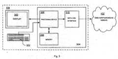
- the apparatus 104 connected to the data communications network 102is further illustrated in fig 3 .
- the apparatus 104is illustrated as a PC generally comprising a display 300, an input device 302, illustrated as a keyboard, and a computing unit 304, wherein the computing unit 304 further comprises a processing device 306, a memory 308 and a data communication interface 310 communicating with the data communications network 102.
- Datais received from and transmitted to the data communications network 102 via the data communications interface 310, which can be similar to the data communication interface 210 of the camera 200.
- the received datais transferred to the processing device 306, in which the data is processed.
- This processingcan comprise, if the received data is image data from the camera 300, transferring the received image data to the display 300.
- Datacan also be received by the processing device 306 from the input device 302.
- Such datacan, for instance, be data describing changes, or new values, of the camera parameter values, input by the user of the input device 302 to be transferred through the data communications network 102 to the camera 100.
- the apparatus 104is illustrated as a PC, the apparatus can, in another emodiment, be a mobile terminal, a PDA or any other device having a display and processing capabilities.
- the input device 302can communicate wirelessly with the computing unit 304.
- the input device 302can be embodied as a remote control communicating with a computing unit 304 via IR light.
- the input device 302can be a mobile terminal communicating with the computing unit 304 via a mobile terminal communications network, such as a GSM network.
- a mobile terminal network communications interfacemay have to be added to the computing unit 304.
- An alternative approachbased on that the changes are made in the cameras 100a-100f, is that the apparatus 104 can be divided into an input sub-apparatus and an output sub-apparatus.
- the input sub-apparatuscan be a mobile terminal, which communicates directly with the cameras 100a-104f via a mobile terminal communications network, such as a GSM network, which implies that a mobile terminal network communications interface have to be added to the cameras 100a-100f.
- a mobile terminal communications networksuch as a GSM network
- the output sub-apparatuscan be a TV set, or other suitable equipment, adapted to show image data from a number of cameras simultaneously, which TV set is adapted to receive image data broadcasted from the cameras 100a-100f, which implies that a broadcasting interface is, in this alternative approach, added to each of the cameras 100a-100f.
- referencesare added in the image data shown by the output sub-apparatus.
- Fig 4illustrates an example of a Graphical User Interface (GUI) 400 of the apparatus according to the present invention.
- GUIGraphical User Interface
- the GUI 400comprises a parameter values part 402.
- the available parameter valuesare indicated, and a control button for each of the parameter values is available for adjustment of the respective parameter values.
- the control buttonis embodied as a slider, where the rightmost position implies a high parameter value and the leftmost position implies a low parameter value.
- an image data part 404the image data from a number of cameras is shown simultaneously.
- image data from four different camerasis shown in four different image data areas 420a, 420b, 420c, 420d.
- the image data areas 420a, 420b, 420c, 420dmay represent image data from the cameras 100a, 100b, 100c and 100d, respectively.
- a frame 406a, 406b, 406c, 406dcan be placed around each of the image data areas 420a, 420b, 420c, 420d.
- the image data areacan be activated 420c, illustrated in the figures with dashed lines, or deactivated 420a, 420b, 420d.
- an image data area 420cis activated, the changes made in the parameter values part 402 will be applied to the camera represented by this activated image data area 420c when the new parameter values are transmitted to the cameras.
- the image datamay comprise a text or symbol 407, such as company name or a logo.
- the text 407can be added to the image data by a user. When the text 407 is added to the image data from a specific camera, it can be shown in the image data part 404.
- the text 407is stored in the memory 206 of the camera 100. In this way, regardless of which apparatus that is used for displaying the image data, the text will be shown. Further, the transparency of the text or logo may be one of the parameter values.
- an update image data checkbox 422a, 422b, 422c, 422dmay be associated to each of the image data areas 420a, 420b, 420c, 420d.
- the checkboxis activated 422b, 422c the image data in the associated image data area 420b, 420c is set to be updated with new image data when new image data is requested, i.e. the cameras corresponding to the image data areas 420b, 420c are set to belong to a second subset of cameras which will be further described in figs 6, 7, 8 and 9 .
- the checkbox 422cmay be automatically activated when the frame 420c around a certain image data area 406c is activated.
- a number of templatesi.e. a set of parameter values for a certain environment, is available.
- the templatesare presented in a template area 408, and a current template 410 can be indicated as darker than the rest of the templates.
- a button area 412comprising a "set text/logo” button 414, an “update images” button 416 and a “done” button 418 is presented.
- the "set text/logo" button 414is utilised for setting the text or the logo 407.
- a new windowcan be shown, where a set of tools is presented for creating a text or logo, or a dialog box can be shown where a file containing a text or logo can be chosen and thereafter be set as the text or logo 407.
- the text or logo 407may be stored temporarily in the apparatus 104 in order to be transmitted to the camera/cameras 100a-100f together with the parameter values.
- the text or logo 407is transmitted instantly to the camera/cameras 100a-100f.
- the "update images" button 416is utilised for updating the parameter values in the camera/cameras 100c corresponding to the activated frame/frames 406c and for downloading new image data from the camera/cameras 100b,100c corresponding to the activated update image data checkboxes 422b, 422c.
- the new parameter valueswhich are set with the sliders in the parameter values part, are transmitted to the camera/cameras being indicated via the frames 406a-406d.
- the new parameter valuesare received by the camera/cameras and the present parameter values stored in the memory of the camera 206 are replaced by the received new parameter values.
- the present parameter values stored in the memory of the camera 206are replaced by the received new parameter values.
- only the parameter values in the camera 100cis indicated to be updated.
- new image datais retrieved from the cameras being indicated via the update image checkboxes 422b, 422c. For instance, this may be made by sending an image request to the indicated camera/cameras, in this case the cameras 100b, 100c.
- An appropriate way to workis to first set a template to each of the cameras, e.g. the two middlemost image data areas 420b, 420c in fig 4 present image data from an outdoor environment and are hence related to a template corresponding to the an outdoor environment. Thereafter, based on the outdoor environment template, a fine adjustment of the parameter values can be made manually by adjusting the parameter value slides in the parameter values part 402.
- the "Done" button 418is pressed, which can be seen as a user acceptance signal.
- Fig 5shows a flow chart illustrating the general steps of a method for configuring parameter values for a number of cameras according to the present invention, reference is also made to details of figs 1 and 3 .
- a connectionis set up between the apparatus 104 and the cameras 100a-100f. This connection can be set up through the data communications network 102.
- test image data and parameter valuesare acquired by the apparatus 104 from the cameras 100a-100f.
- a third step 504the acquired test image data and parameter values are shown on the display 300 of the apparatus 104.
- a fourth step 506it is investigated whether the acquired image data from the cameras 100a-100f have a similar appearance, e.g. that a specific green object is represented with the same green colour in the image data from each of the cameras 100a-100f.
- This fourth step 506can be performed manually by the user of the apparatus 104. For instance, by using a GUI as is described in fig 4 .
- this fourth step 506is made automatically, e.g. the apparatus determines a reference camera, and adjusts the remaining cameras in accordance with the reference camera.
- the methodenters a fifth step 508.
- the parameter valuesare changed. This can be made by choosing a template, or by configuring each of the parameter values separately.
- the updated parameter valuesare transmitted to the cameras 100a-100f.
- a seventh step 512the parameter values of the cameras are updated in accordance with the received changed parameter values.
- the methodis repeated from the second step 502, i.e. test image data are acquired once again, and so on, until the image data from the cameras is considered to have a similar appearance.
- the changed parameter valuesare transmitted from the apparatus 104 to the cameras 100a-100f in the sixth step 510, the changed parameter values does not necessarily have to be acquired from the cameras 100a-100f when the second step 502 is repeated. However, if many users are able to change the parameter values of the cameras 100a-100f, there may be a good reason to acquire the changed parameter values.
- the methodis an iterative method, which means that the steps of the method will be repeated until the user, or the apparatus, considers the image data from the cameras to have.a similar appearance. Essentially, an unlimited number of iterations can be made.
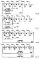
- Fig 6, 7, 8 and 9illustrates a first, a second, a third and a fourth embodiment of the present invention, respectively.
- six different cameras 100a-100fare available and connected to the apparatus 104 in accordance with fig 1 .
- the actual number of camerasmay be less than or more than six in other embodiments.
- image datais initially received from all of the cameras 100a-100f and is shown on the display 300. Then, a first subset comprising some of the cameras is not considered to have image data with the same appearance as the image data of the remaining cameras, whereas the parameter values of the cameras included within the first subset are changed. Thereafter, changed image data is acquired from a second subset comprising at least the cameras of the first subset.
- the first subset 600comprises the cameras 100a-100b and the second subset 602 comprises the cameras 100a-100d.
- image data from cameras with changed parameter values as well as image data from cameras with unchanged parameter valuesare generated at the same point of time. This implies that the conditions are improved for the decision whether the image data is similar or not.
- the configuration of parameter valueswill not be disturbed, since all sets of image data from cameras 100a-100d are generated at the same point of time, either before the light is being lit or after the light is being lit.
- the reason for not including the cameras 100e-100f in the second subsetcan be that the lighting conditions of the environments being monitored by the cameras 100e-100f differ strongly from the environments being monitored by the cameras 100a-100d included in the second subset 602.
- the environments being monitored by the cameras 100a-100d included in the second subset 602may be indoor environments, and the environments being monitored by the cameras 100e-100f may be environments illuminated by an IR light.
- Fig 7illustrates the second embodiment.
- a first subset 700as well as a second subset 702, comprises the cameras 100a-100b.
- This embodimentcan be relevant if the cameras 100a-100b are the only ones monitoring a certain lighting environment and none of the cameras, 100a-100b have proper parameter values.
- Fig 8illustrates a third embodiment.
- a first subset 800comprises the cameras 100a-100b and a second subset 802 comprises all of the cameras 100a-100f.
- This embodimentcan be relevant if all of the cameras are monitoring environments with the same lighting conditions and the cameras 100a-100b are the only ones not having proper parameter values.
- Fig 9illustrates a fourth embodiment.
- a first subset 900as well as a second subset 902, comprises all of the cameras 100a-100f.
- An advantage of having the first subset 600/700/800/900 and the second subset 602/702/802/902, respectively,is that only the required image data is transmitted from the cameras 100a-100f to the apparatus 104 during the configuration of parameter values. This implies less unnecessary usage of the datacommunications network 102.
- the present inventionis realised as a computer program, it can be made in such a way that it is possible for the user to determine the first and second subset easily. For instance, this can be realised by having checkboxes 422a, 422b, 422c, 422d associated to each of the cameras 100a-100d, which checkbox indicates whether each camera is associated to the second subset 602/702/802/902 or not. If the parameter values for a camera is changed, the camera can be automatically associated to the first subset 600/700/800/900, as well as the second subset 602/702/802/902.
- the method for configuring parameter values for a plurality of camerasmay be described with reference to Fig 10 .
- the steps of this methodmay be performed in the apparatus 104.
- image datais acquired from the plurality of cameras 100a-100f.
- a second step 1002the image data is buffered.
- a third step 1004the image data is displayed.
- a fourth step 1006at least one parameter value is changed for a first subset of cameras 600/700/800/900.
- a fifth step 1008the at least one parameter value is transmitted to the first subset of cameras 600/700/800/900.
- changed image datais acquired from a second subset of cameras 602/702/802/902.
- a seventh step 1012the buffered image data for the second subset of cameras 602/702/802/902 is replaced with the changed image data for the second subset of cameras 602/702/802/902.
- a method for parameter value configuration of a camera 100 coupled to an apparatus 104 through a data communications network 102will now be described with reference to Fig 11 . The steps of this method will be performed in the camera.
- a first step 1100an image data request from the apparatus 104 is received by the camera 100.
- image datais generated by the camera 100.
- a third step 1104the image data is transmitted from the camera 100 to the apparatus 104.
- a parameter value change request from the apparatus 104is received by the camera 100.
- a fifth step 1108the parameter values are changed based upon the parameter value change request.
- new image data based on the changed parameter valuesis generated by the camera 100.
- a seventh step 1112the new image data is transmitted to the apparatus 104 through the data communications network 102.
Landscapes
- Engineering & Computer Science (AREA)
- Multimedia (AREA)
- Signal Processing (AREA)
- Human Computer Interaction (AREA)
- Physics & Mathematics (AREA)
- General Physics & Mathematics (AREA)
- Library & Information Science (AREA)
- Studio Devices (AREA)
- Closed-Circuit Television Systems (AREA)
- Selective Calling Equipment (AREA)
- Telephonic Communication Services (AREA)
Description
- The present invention generally relates to a method for configuring parameter values for a plurality of cameras, an apparatus comprising a processing device, a display adapted for showing image data, an input device, a memory adapted for holding a number of parameter values and for buffering image data, and a data communication interface adapted for communication through a data communications network with a plurality of cameras, a method for parameter value configuration of a camera, a camera having a processor device, a memory adapted for holding a number of parameter values, and a data communication interface adapted for communication through a data communications network, said camera stores parameter values which control the appearance of image data captured by said camera, a system for configuration of at least one parameter value in a plurality of cameras, comprising a camera and an apparatus, and a computer program.
- A modern security system often comprises a number of surveillance cameras. The surveillance cameras give the security personnel a possibility to monitor a large,area, such as several floors in an office building.
- When having a number of cameras, the appearance of the images from the number of cameras should preferably be substantially similar with respect to brightness, sharpness, etc., since this makes the work of the operator less tiresome. More particularly, for a human eye, it is less tiresome analysing a number of images having similar apperance, than analysing a number of images with dissimilar appearance.
- When having a number of cameras, the cameras are most often placed at different places having different light conditions, which makes predetermined settings a non-optimal alternative. Further, the number of cameras may be different types of cameras with, for example, different types of image sensors, which even further make predetermined settings a non-optimal alternative.
US 2003/0234866A1 describes a practical real-time calibration of digital omnidirectional cameras in the areas of de-vignetting, brightness, contrast and white balance control. Novel solutions for the colour calibration of an omnidirectional camera rig, and an efficient method for devignetting images are also presented. Additionally, a context-specific method of stitching images together into a panorama or a mosaic is provided.WO 03/041411 WO 2006/041991 discloses a video monitoring system which includes a video monitor configured to receive a video image from a video source such as a video camera, decompress the video image, and display the video image on a display screen according to a display format. The video monitor may be used to adjust one or more video parameters of the video image. The video monitor may further be configured to transmit the video image to a remote video device such as a remote video monitor or video recorder.- In view of the above, an objective of the invention is to solve or at least reduce the problems discussed above. In particular, an objective is to provide a method for configuring parameter values for a plurality of cameras, wherein an image feedback is provided after a reconfiguration of the parameter values.
- The plurality of cameras may be all the cameras connected to a certain data communications network, but may also be a subset of cameras connected to the data communications network.
- Image data generated by the cameras may be analog or digital, but preferably digital. Further, the image data may be still pictures, as well as video sequences. In one embodiment, the plurality of cameras generate video sequences normally, but still pictures as image feedback.
- A first aspect of the invention is a method for configuring parameter values for a plurality of cameras, comprising acquiring image data from said plurality of cameras, said cameras store parameter values which control the appearance of image data captured by said cameras, buffering said image data from said plurality of cameras, displaying said buffered image data from said plurality of cameras, changing at least one parameter value for a first subset of said plurality of cameras, transmitting said at least one changed parameter value to said first subset of cameras to allow update of said at least one parameter value in each camera in said first subset, acquiring changed image data from a second subset of said plurality of cameras comprising at least the cameras of the first subset, replacing said buffered image data for said second subset of cameras with said changed image data for said second subset of cameras, and displaying said buffered image data for said plurality of cameras.
- An advantage with this first aspect is that an image feedback is given after changing the parameter values. In this way the user of an apparatus, configured to perform the steps according to the method of the first aspect, will easily see if the change of parameter values produced the desired result or not.
- The first subset of the method may be a part of the second subset.
- Alternatively, the first subset may be equal to the second subset.
- Alternatively, the second subset may be equal to the plurality of cameras.
- The changing may involve receiving a user input from a user, and changing said at least one parameter value in accordance with said user input.
- An advantage of this is that the user of the apparatus, performing the steps of the method according to the first aspect, may determine for himself in which way the parameter values is to be changed.
- Alternatively, the changing may involve determining reference image data, calculating a correction value based on said reference image data, and changing said at least one parameter value in accordance with said correction value.
- An advantage of this is that no user interaction is required, which implies that the configuration of the parameter values may be made quickly.
- The step of acquiring image data according to the first aspect of the invention may involve transmitting an image data request to said plurality of cameras.
- The method according to the first aspect may further involve retrieving at least one parameter value from a predetermined set of parameter values.
- An advantage of this is that a number of sets of predetermined parameter values for different environments may be provided to the user of the apparatus, performing the steps according to the method of the first aspect, wherein each such set of predetermined parameter values will function as a selectable template. In this way a first approximation of suitable parameter values may be easily and quickly done by the user of the apparatus by selecting the desired set of predetermined parameter values.
- The set of predetermined parameter values may be selected from a group consisting of, but not limited to: a set of predetermined parameter values adapted for outdoor conditions, a set of predetermined parameter values adapted for indoor conditions, a set of predetermined parameter values adapted for fluorescent lighting conditions, a set of predetermined parameter values adapted for incandescent light conditions and a set of predetermined parameter values adapted for infrared light conditions.
- The step of retreiving may further involve receiving a user input from a user, and retrieving said set of predetermined parameter values in accordance with said user input.
- The at least one parameter value may be selected from a group consisting of, but not limited to: a white balance value, a contrast value, a rotation value, a compression value, a sharpness value and a colour balance value.
- Further, the parameter values may be acquired together with said image data.from said plurality of cameras in said acquiring of image data and are displayed in said displaying of image data together with said image data.
- Moreover, acquiring of said image data, buffering of said image data, displaying of said image data, changing of at least one parameter value for said first subset, transmitting of said at least one parameter value, acquiring of changed image data from said second subset, replacing of said buffered image data for said second subset, and displaying of said buffered image data, may be repeated iteratively until a user acceptance signal is received from a user.
- A second aspect of the invention is an apparatus comprising a processing device, a display adapted for showing image data, :an input device, a memory adapted for holding a number of parameter values and for buffering image data, and a data communication interface adapted for communication through a data communications network with a plurality of cameras, wherein the processing device being adapted to acquire image data from said plurality of cameras, buffer said image data from said plurality of cameras in said memory, display said buffered image data from said plurality of cameras on said display, change at least one parameter value for a first subset of said plurality of cameras based upon an actuation of said input device, transmit said at least one parameter value to said first subset of cameras through said data communications network, to allow update of said at least one parameter value in each camera in said first subset, acquire changed image data from a second subset of said plurality of cameras through said data communications network, replace said buffered image data for said second subset of cameras with said changed image data for said second subset of cameras in said memory, and display said buffered image data for said plurality of cameras on said display.
- The apparatus according to the second aspect may comprise a personal computer (PC).
- An advantage of this is that any PC connected to a LAN (Local Area Network) to which a plurality of camerasis connected may be used as the apparatus according to the second aspect of the invention.
- The apparatus according to the second aspect may alternatively comprise a mobile terminal.
- The apparatus according to the second aspect of the invention may be adapted to perform the method according to the first aspect of the invention.
- A third aspect of the invention is a method for parameter value configuration of a camera coupled to an apparatus through a data communications network, said camera stores parameter values which control the appearance of image data captured by said camera, whereby the steps, in said camera, of receiving an image data request from said apparatus, generating image data, using said parameter values, upon receiving said image data request, transmitting said image data to said apparatus, receiving a parameter value change request from said apparatus, changing at least one parameter value among said parameter values held in said camera based upon said parameter value change request, generating, using said parameter values as changed, changed image data, and transmitting said changed image data to said apparatus through said data communications network.
- A fourth aspect of the invention is a camera having a processing device, a memory adapted for holding a number a parameter values, and a data communication interface adapted for communication through a data communications network, said camera stores parameter values which control the appearance of image data captured by said camera, whereby the processing device being adapted to receive an image data request from an apparatus through said data communications network, generate image data, using said parameter values, upon receiving said received image data request, transmit said image data to said apparatus through said data communications network, receive a parameter value change request from said apparatus through said data communications network, change at least one parameter value among said parameter values held in said memory in accordance with said parameter value change request, generate, using said parameter values as changed, changed image data, with said parameter values being changed, upon said parameter value change request, and transmit said changed image data to said apparatus through said data communications network.
- A fifth aspect of the invention is a system for configuration of at least one parameter value in a plurality of cameras, comprising a data communications network, an apparatus according to the fourth aspect, connected to said data communications network, and a plurality of cameras configured for communication with said apparatus through said data communications network.
- A sixth aspect of the invention is a computer program, comprising computer program code for performing the steps of the method according to the first aspect.
- The third to sixth aspects of the invention may have substantially the same or corresponding features, whenever applicable, as the first and second aspects.
- Other objectives, features and advantages of the present invention will appear from the following detailed disclosure, from the attached dependent claims as well as from the drawings.
- Generally, all terms used in the claims are to be interpreted according to their ordinary meaning in the technical field, unless explicitly defined otherwise herein. All references to "a/an/the [element, device, component, means, step, etc]" are to be interpreted openly as referring to at least one in-stance of said element, device, component, means, step, etc., unless explicitly stated otherwise. The steps of any method disclosed herein do not have to be performed in the exact order disclosed, unless explicitly stated.
- The above, as well as additional objects, features and advantages of the present invention, will be better understood through the following illustrative and nonlimiting detailed description of preferred embodiments of the present invention, with reference to the appended drawings, where the same reference numerals will be used for similar elements, wherein:
Fig 1 illustrates a general surveillance camera system comprising a plurality of cameras, a data communications network and an apparatus.Fig 2 illustrates one of the plurality of cameras in the general surveillance camera system in more detail.Fig 3 illustrates the apparatus in the general surveillance camera system in more detail.Fig 4 illustrates a graphical user interface of the apparatus.Fig 5 illustrates a flow chart describing a general method for configuring a number of cameras.Fig 6 illustrates a first embodiment of the present invention.Fig 7 illustrates a second embodiment of the present invention.Fig 8 illustrates a third embodiment of the present invention.Fig 9 illustrates a fourth embodiment of the present invention.Fig 10 illustrates a method for configuring parameter values.Fig 11 illustrates a method for parameter configuration of a camera.Fig 1 illustrates a general surveillance camera system with a plurality ofcameras 100a-100f. Each camera is connected to adata communications network 102, such as a TCP/IP-based Local Area Network (LAN) or a TCP/IP-based Wireless Local Area Network (WLAN). Anapparatus 104 for receiving and presenting image data from thecameras 100a-100f is also connected to the data communications network.- Although it is a great advantage to use an established standard such as the TCP/IP, this is not a must. Actually, any data communications network adapted to pass information, analog as well as digital, from cameras to an apparatus may be utilised for realising the present invention.
- Moreover, the
apparatus 104 can also be utilised for configuring the parameter values for eachcamera 100a-100f. This may, for instance, be to set the sharpness value for each of the camera to an appropriate value. - In
fig 1 , only one apparatus is shown. It is only required one apparatus to realise the invention, however, there may be more than one apparatus present. Fig 2 illustrates one of thecameras 100a-100f connected to thedata communications network 102, shown infig 1 in more detail.- The
camera 100 comprises alens 200, animage sensor 202, aprocessing device 204, amemory 206, acompression engine 208 and adata communication interface 210. - The
lens 200 comprises optics adapted to focus incoming light onto the image sensor. Further, a number of associated devices for controlling the incoming light may be associated to thelens 200, such as a shutter for adjusting the amount of light and an exposure time control device for controlling the exposure time of the camera. Hereinafter, when referring to thelens 200 the associated devices should be included as well. - Generally, light is transferred via the
lens 200 to theimage sensor 202. In theimage sensor 202, an image is captured by generating image data which is thereafter transferred to theprocessing device 204. Theprocessing device 204 can be one or several processors adapted to process the image data generated by theimage sensor 202. Such processing can be motion detection, adding a time stamp to the present image data, and changing the parameter values of theimage sensor 202. The processing device can, for instance, be an ETRAX 100LX 32-bit ASIC which is made commercially available by AXIS Communications AB. - Further, the
memory 206 is utilised by theprocessing device 204, e.g. for storing parameter values. The memory can be divided into a RAM memory and a Flash memory. - Therafter, the image data is transferred to the
compression engine 208. In the compression engine the image data is compressed in accordance with a compression format, such as MPEG-4 or Motion-JPEG. - Finally, the compressed image data is output to the
data communications network 102 via thedata communication Interface 210. The data communication interface can be Ethernet-compliant in the physical form of an RJ-45 connector. - Additionally, the
camera 100 is adapted to receive new parameter values via thedata communications network 102 utilising thedata network interface 210. After having received new paramter values the present parameter values stored in thememory 206 can, by using theprocessing device 204, be replaced by the received new parameter values. - Moreover, the camera comprises some sort of power supply (not shown), such as a battery, or is connected to the mains via an electric cable or via an electric cable comprised within an Ethernet cable (known as Power over Ethernet (IEEE 802.3af)).
- The
apparatus 104 connected to thedata communications network 102 is further illustrated infig 3 . - In
fig 3 , theapparatus 104 is illustrated as a PC generally comprising adisplay 300, aninput device 302, illustrated as a keyboard, and acomputing unit 304, wherein thecomputing unit 304 further comprises aprocessing device 306, amemory 308 and adata communication interface 310 communicating with thedata communications network 102. - Data is received from and transmitted to the
data communications network 102 via thedata communications interface 310, which can be similar to thedata communication interface 210 of thecamera 200. - The received data is transferred to the
processing device 306, in which the data is processed. This processing can comprise, if the received data is image data from thecamera 300, transferring the received image data to thedisplay 300. - Data can also be received by the
processing device 306 from theinput device 302. Such data can, for instance, be data describing changes, or new values, of the camera parameter values, input by the user of theinput device 302 to be transferred through thedata communications network 102 to thecamera 100. - Although the
apparatus 104 is illustrated as a PC, the apparatus can, in another emodiment, be a mobile terminal, a PDA or any other device having a display and processing capabilities. - As an alternative to the wire-based keyboard illustrated in
fig 3 , theinput device 302 can communicate wirelessly with thecomputing unit 304. For instance, theinput device 302 can be embodied as a remote control communicating with acomputing unit 304 via IR light. - In another embodiment, the
input device 302 can be a mobile terminal communicating with thecomputing unit 304 via a mobile terminal communications network, such as a GSM network. In this embodiment, a mobile terminal network communications interface may have to be added to thecomputing unit 304. - An alternative approach, based on that the changes are made in the
cameras 100a-100f, is that theapparatus 104 can be divided into an input sub-apparatus and an output sub-apparatus. - The input sub-apparatus can be a mobile terminal, which communicates directly with the
cameras 100a-104f via a mobile terminal communications network, such as a GSM network, which implies that a mobile terminal network communications interface have to be added to thecameras 100a-100f. - The output sub-apparatus can be a TV set, or other suitable equipment, adapted to show image data from a number of cameras simultaneously, which TV set is adapted to receive image data broadcasted from the
cameras 100a-100f, which implies that a broadcasting interface is, in this alternative approach, added to each of thecameras 100a-100f. - In order to relate the information transmitted from the input sub-apparatus to a specific function, references are added in the image data shown by the output sub-apparatus.
Fig 4 illustrates an example of a Graphical User Interface (GUI) 400 of the apparatus according to the present invention.- The
GUI 400 comprises a parameter valuespart 402. In this part, the available parameter values are indicated, and a control button for each of the parameter values is available for adjustment of the respective parameter values. In this example, the control button is embodied as a slider, where the rightmost position implies a high parameter value and the leftmost position implies a low parameter value. - In an
image data part 404, the image data from a number of cameras is shown simultaneously. In this example, image data from four different cameras is shown in four differentimage data areas - For instance, the
image data areas cameras - A
frame image data areas image data area 420c is activated, the changes made in the parameter valuespart 402 will be applied to the camera represented by this activatedimage data area 420c when the new parameter values are transmitted to the cameras. - The image data may comprise a text or
symbol 407, such as company name or a logo. Thetext 407 can be added to the image data by a user. When thetext 407 is added to the image data from a specific camera, it can be shown in theimage data part 404. - Advantageously, the
text 407 is stored in thememory 206 of thecamera 100. In this way, regardless of which apparatus that is used for displaying the image data, the text will be shown. Further, the transparency of the text or logo may be one of the parameter values. - Further, an update image data checkbox 422a, 422b, 422c, 422d may be associated to each of the
image data areas image data area 420b, 420c is set to be updated with new image data when new image data is requested, i.e. the cameras corresponding to theimage data areas 420b, 420c are set to belong to a second subset of cameras which will be further described infigs 6, 7, 8 and 9 . - Advantageously, since an image feedback most often is preferred after having changed the parameter values, the
checkbox 422c may be automatically activated when theframe 420c around a certain image data area 406c is activated. - In order to facilitate and improve the parameter values, a number of templates, i.e. a set of parameter values for a certain environment, is available. The templates are presented in a
template area 408, and acurrent template 410 can be indicated as darker than the rest of the templates. - A
button area 412 comprising a "set text/logo"button 414, an "update images"button 416 and a "done"button 418 is presented. - The "set text/logo"
button 414 is utilised for setting the text or thelogo 407. When thebutton 414 is pressed a new window can be shown, where a set of tools is presented for creating a text or logo, or a dialog box can be shown where a file containing a text or logo can be chosen and thereafter be set as the text orlogo 407. After the text orlogo 407 has been created or chosen, it may be stored temporarily in theapparatus 104 in order to be transmitted to the camera/cameras 100a-100f together with the parameter values. Alternatively, the text orlogo 407 is transmitted instantly to the camera/cameras 100a-100f. - The "update images"
button 416 is utilised for updating the parameter values in the camera/cameras 100c corresponding to the activated frame/frames 406c and for downloading new image data from the camera/cameras image data checkboxes - More specifically, in a first step, the new parameter values, which are set with the sliders in the parameter values part, are transmitted to the camera/cameras being indicated via the
frames 406a-406d. Next, the new parameter values are received by the camera/cameras and the present parameter values stored in the memory of thecamera 206 are replaced by the received new parameter values. In the case illustrated infig 4 , only the parameter values in thecamera 100c is indicated to be updated. - In a second step, new image data is retrieved from the cameras being indicated via the
update image checkboxes cameras - In this way, when a parameter value change is made, the "update images"
button 416 can be pressed, and a result of the parameter value change is shown. Hence, an image feedback is automatically given for every change, which is an advantage. Moreover, image feedback may be given for every chosen camera connected to the data communications network, which means that if the appearance of the image data for a number of cameras is not similar, this will easily be noticed by the user. - An appropriate way to work is to first set a template to each of the cameras, e.g. the two middlemost
image data areas 420b, 420c infig 4 present image data from an outdoor environment and are hence related to a template corresponding to the an outdoor environment. Thereafter, based on the outdoor environment template, a fine adjustment of the parameter values can be made manually by adjusting the parameter value slides in the parameter valuespart 402. - When the
image data areas button 418 is pressed, which can be seen as a user acceptance signal. Fig 5 shows a flow chart illustrating the general steps of a method for configuring parameter values for a number of cameras according to the present invention, reference is also made to details offigs 1 and3 .- In a
first step 500, a connection is set up between theapparatus 104 and thecameras 100a-100f. This connection can be set up through thedata communications network 102. - In a
second step 502, test image data and parameter values are acquired by theapparatus 104 from thecameras 100a-100f. - In a
third step 504, the acquired test image data and parameter values are shown on thedisplay 300 of theapparatus 104. - In a
fourth step 506, it is investigated whether the acquired image data from thecameras 100a-100f have a similar appearance, e.g. that a specific green object is represented with the same green colour in the image data from each of thecameras 100a-100f. - This
fourth step 506 can be performed manually by the user of theapparatus 104. For instance, by using a GUI as is described infig 4 . - Alternatively, this
fourth step 506 is made automatically, e.g. the apparatus determines a reference camera, and adjusts the remaining cameras in accordance with the reference camera. - This can be done by choosing reference image data originating from the reference camera, calculating a number of characteristic values for the reference image data, such as the mean red value, comparing the characteristic values of the reference image data with the corresponding characteristic values of the image data originating from one or several of the other cameras, calculating a correction value, or values, based on the comparison, and changing the parameter values in the one or several other cameras in accordance with the correction value.
- If the image data from the
cameras 100a-100f is considered to have a similar appearance, the parameter values are configured correctly, and conversely, if the image data from thecameras 100a-100f are not considered to have a similar appearance, the method enters afifth step 508. - In the
fifth step 508, the parameter values are changed. This can be made by choosing a template, or by configuring each of the parameter values separately. - In a
sixth step 510, the updated parameter values are transmitted to thecameras 100a-100f. - Thereafter, in a
seventh step 512, the parameter values of the cameras are updated in accordance with the received changed parameter values. - Next, the method is repeated from the
second step 502, i.e. test image data are acquired once again, and so on, until the image data from the cameras is considered to have a similar appearance. - Since the changed parameter values are transmitted from the
apparatus 104 to thecameras 100a-100f in thesixth step 510, the changed parameter values does not necessarily have to be acquired from thecameras 100a-100f when thesecond step 502 is repeated. However, if many users are able to change the parameter values of thecameras 100a-100f, there may be a good reason to acquire the changed parameter values. - To sum up, the method is an iterative method, which means that the steps of the method will be repeated until the user, or the apparatus, considers the image data from the cameras to have.a similar appearance. Essentially, an unlimited number of iterations can be made.
Fig 6, 7, 8 and 9 illustrates a first, a second, a third and a fourth embodiment of the present invention, respectively. In all the embodiments, sixdifferent cameras 100a-100f are available and connected to theapparatus 104 in accordance withfig 1 . The actual number of cameras may be less than or more than six in other embodiments.- Generally, in all of the embodiments, image data is initially received from all of the
cameras 100a-100f and is shown on thedisplay 300. Then, a first subset comprising some of the cameras is not considered to have image data with the same appearance as the image data of the remaining cameras, whereas the parameter values of the cameras included within the first subset are changed. Thereafter, changed image data is acquired from a second subset comprising at least the cameras of the first subset. - In the first embodiment, illustrated in
fig 6 , thefirst subset 600 comprises thecameras 100a-100b and thesecond subset 602 comprises thecameras 100a-100d. - By including more cameras in the second subset than in the first subset, image data from cameras with changed parameter values as well as image data from cameras with unchanged parameter values are generated at the same point of time. This implies that the conditions are improved for the decision whether the image data is similar or not.
- For instance, if the
cameras 100a-100d, i.e. the second subset, are monitoring a room, and a light is being lit in the room, the configuration of parameter values will not be disturbed, since all sets of image data fromcameras 100a-100d are generated at the same point of time, either before the light is being lit or after the light is being lit. - The reason for not including the
cameras 100e-100f in the second subset can be that the lighting conditions of the environments being monitored by thecameras 100e-100f differ strongly from the environments being monitored by thecameras 100a-100d included in thesecond subset 602. - For instance, the environments being monitored by the
cameras 100a-100d included in thesecond subset 602 may be indoor environments, and the environments being monitored by thecameras 100e-100f may be environments illuminated by an IR light. Fig 7 illustrates the second embodiment. In this embodiment afirst subset 700, as well as asecond subset 702, comprises thecameras 100a-100b.- This embodiment can be relevant if the
cameras 100a-100b are the only ones monitoring a certain lighting environment and none of the cameras, 100a-100b have proper parameter values. Fig 8 illustrates a third embodiment. In this embodiment, afirst subset 800 comprises thecameras 100a-100b and asecond subset 802 comprises all of thecameras 100a-100f.- This embodiment can be relevant if all of the cameras are monitoring environments with the same lighting conditions and the
cameras 100a-100b are the only ones not having proper parameter values. Fig 9 illustrates a fourth embodiment. In this emodiment, afirst subset 900, as well as asecond subset 902, comprises all of thecameras 100a-100f.- If all of the cameras are not having proper parameter values, this embodiment can be relevant.
- An advantage of having the
first subset 600/700/800/900 and thesecond subset 602/702/802/902, respectively, is that only the required image data is transmitted from thecameras 100a-100f to theapparatus 104 during the configuration of parameter values. This implies less unnecessary usage of thedatacommunications network 102. - If the present invention is realised as a computer program, it can be made in such a way that it is possible for the user to determine the first and second subset easily. For instance, this can be realised by having
checkboxes cameras 100a-100d, which checkbox indicates whether each camera is associated to thesecond subset 602/702/802/902 or not. If the parameter values for a camera is changed, the camera can be automatically associated to thefirst subset 600/700/800/900, as well as thesecond subset 602/702/802/902. - According to another aspect, the method for configuring parameter values for a plurality of cameras may be described with reference to
Fig 10 . The steps of this method may be performed in theapparatus 104. - In a
first step 1000, image data is acquired from the plurality ofcameras 100a-100f. - In a
second step 1002, the image data is buffered. - In a
third step 1004, the image data is displayed. - In a
fourth step 1006, at least one parameter value is changed for a first subset ofcameras 600/700/800/900. - In a fifth step 1008, the at least one parameter value is transmitted to the first subset of
cameras 600/700/800/900. - In a
sixth step 1010, changed image data is acquired from a second subset ofcameras 602/702/802/902. - In a
seventh step 1012, the buffered image data for the second subset ofcameras 602/702/802/902 is replaced with the changed image data for the second subset ofcameras 602/702/802/902. - Finally, in an
eighth step 1014, the image data for the plurality ofcameras 100a-100f is displayed. - A method for parameter value configuration of a
camera 100 coupled to anapparatus 104 through adata communications network 102 will now be described with reference toFig 11 . The steps of this method will be performed in the camera. - In a
first step 1100, an image data request from theapparatus 104 is received by thecamera 100. - In a
second step 1102, image data is generated by thecamera 100. - In a
third step 1104, the image data is transmitted from thecamera 100 to theapparatus 104. - In a
fourth step 1106, a parameter value change request from theapparatus 104 is received by thecamera 100. - In a
fifth step 1108, the parameter values are changed based upon the parameter value change request. - In a
sixth step 1110, new image data based on the changed parameter values is generated by thecamera 100. - Finally, in a
seventh step 1112, the new image data is transmitted to theapparatus 104 through thedata communications network 102. - The invention has mainly been described above with reference to a few embodiments. However, as is readily appreciated by a person skilled in the art, other embodiments than the ones disclosed above are equally possible within the scope of the invention, as defined by the appended patent claims.
Claims (15)
- An iterative method for configuring parameter values for a plurality of cameras (100a-100f), comprising the iteration
acquiring (1000) image data corresponding to still pictures from said plurality of cameras (100a-100f), said plurality of cameras stores parameter values which control the appearance of image data captured by said plurality of cameras,
buffering (1002) said image data from said plurality of cameras (100a-100f),
displaying (1004), simultaneously, said buffered image data from said plurality of cameras (100a-100f),
changing (1006) at least one parameter value for a first subset (600/700/800/900) of said plurality of cameras, wherein the step of changing is made by choosing a template, wherein the template comprises a set of predetermined parameter values for a certain environment,
transmitting (1008) said set of predetermined parameter values to said first subset (600/700/800/900) of said plurality of cameras to allow update of each camera in accordance with said set of predetermined parameter values,
acquiring (1010) image data corresponding to still pictures from a second subset of said plurality of cameras (100a-100f) comprising at least the cameras of the first subset,
replacing (1012) buffered image data from said second subset (602/702/802/902) of cameras with said acquired image data from said second subset of cameras, and
displaying (1014), simultaneously, said buffered image data for said plurality of cameras (100a-100f),
wherein the iteration is repeated until a user accptance signal is received. - A method according to claim 1, wherein said first subset (600) is a subset of said second subset (602).
- A method according to claim 1, wherein said first subset (700) is equal to said second subset (702).
- A method according to claim 2 or 3, wherein said second subset (802/902) is equal to said plurality of cameras (100a-100f).
- A method according to any preceding claim, wherein said changing involves
receiving a user input from a user, and
changing said at least one parameter value in accordance with said user input. - A method according to any of claims 1-4, wherein said changing involves
determining a reference camera,
calculating a correction value based on image data from said reference camera, and
changing said at least one parameter value in accordance with said correction value. - A method according to any preceding claims, wherein said acquiring of image data involves
transmitting an image data request to said plurality of cameras (100a-100f). - A method according to any of claims 1-7, wherein said set of predetermined parameter values is selected from a group consisting of: a set of predetermined parameter values adapted for outdoor conditions, a set of predetermined parameter values adapted for indoor conditions, a set of predetermined parameter values adapted for fluorescent lighting conditions, a set of predetermined parameter values adapted for incandescent light conditions and a set of predetermined parameter values adapted for infrared light conditions.
- A method according to any preceding claims, wherein said at least one parameter value is selected from a group consisting of: a white balance value, a contrast value, a rotation value, a compression value, a sharpness value and a colour balance value.
- A method according to any preceding claims, wherein said parameter values are acquired together with said image data from said plurality of cameras (100a-100f) in said acquiring of image data and are displayed in said displaying of image data together with said image data.
- An apparatus (104) comprising a processing device (306), a display (300) adapted for showing image data, an input device (302), a memory (308) adapted for holding a number of parameter values and for buffering image data, and a data communication interface (310) adapted for communication through a data communications network (102) with a plurality of cameras (100a-100f),
wherein the processing device (306) is adapted to iteratively
acquire image data corresponding to still pictures from said plurality of cameras (100a-100f),
buffer said image data from said plurality of cameras in said memory (308),
display, simultaneously, said buffered image data from said plurality of cameras on said display (300),
change at least one parameter value for a first subset (600/700/800/900) of said plurality of cameras based upon an actuation of said input device (302), wherein said actuation comprises a template, wherein the template comprises a set of predetermined parameter values for a certain environment,
transmit said set of parameter values to said first subset (600/700/800/900) of cameras through said data communications network (102), to allow update of each camera in said first subset in accordance with said set or predetermined parameter values,
acquire image data corresponding to still pictures from a second subset (602/702/802/902) of said plurality of cameras through said data communications network (102),
replace buffered image data for said second subset (602/702/802/902) of cameras with said acquired image data for said second subset (602/702/802/902) of cameras in said memory (308), and
display, simultaneously, said buffered image data for said plurality of cameras (100a-100f) on said display (300),
wherein the processing device (306) is adapted to perform the iteration until a user accptance signal is received. - An apparatus (104) according to claim 11, wherein said apparatus (104) comprises a personal computer (PC).
- An apparatus (104) according to claim 11, wherein said apparatus (104) comprises a mobile terminal.
- An apparatus (104) according to claim 11-13, wherein said processing device (306) is adapted to perform a method according to any of claims 1-10.
- A computer program, comprising computer program code for performing the steps of the method according to any of claims 1-10.
Priority Applications (6)
| Application Number | Priority Date | Filing Date | Title |
|---|---|---|---|
| EP06116500.7AEP1876828B1 (en) | 2006-07-03 | 2006-07-03 | Method and apparatus for configuring parameter values for cameras |
| TW096122512ATWI403168B (en) | 2006-07-03 | 2007-06-22 | Method and device for constructing camera parameter values |
| US11/771,687US8184168B2 (en) | 2006-07-03 | 2007-06-29 | Method and apparatus for configuring parameter values for cameras |
| CN2007101273449ACN101119479B (en) | 2006-07-03 | 2007-07-02 | Method and apparatus for configuring parameter values for cameras |
| JP2007174132AJP5156285B2 (en) | 2006-07-03 | 2007-07-02 | Method and apparatus for configuring camera parameter values |
| KR1020070066397AKR101319132B1 (en) | 2006-07-03 | 2007-07-03 | Method and apparatus for configuring parameter values for cameras |
Applications Claiming Priority (1)
| Application Number | Priority Date | Filing Date | Title |
|---|---|---|---|
| EP06116500.7AEP1876828B1 (en) | 2006-07-03 | 2006-07-03 | Method and apparatus for configuring parameter values for cameras |
Publications (2)
| Publication Number | Publication Date |
|---|---|
| EP1876828A1 EP1876828A1 (en) | 2008-01-09 |
| EP1876828B1true EP1876828B1 (en) | 2016-10-26 |
Family
ID=37670974
Family Applications (1)
| Application Number | Title | Priority Date | Filing Date |
|---|---|---|---|
| EP06116500.7AActiveEP1876828B1 (en) | 2006-07-03 | 2006-07-03 | Method and apparatus for configuring parameter values for cameras |
Country Status (6)
| Country | Link |
|---|---|
| US (1) | US8184168B2 (en) |
| EP (1) | EP1876828B1 (en) |
| JP (1) | JP5156285B2 (en) |
| KR (1) | KR101319132B1 (en) |
| CN (1) | CN101119479B (en) |
| TW (1) | TWI403168B (en) |
Families Citing this family (44)
| Publication number | Priority date | Publication date | Assignee | Title |
|---|---|---|---|---|
| JP5076717B2 (en)* | 2007-08-06 | 2012-11-21 | 株式会社ニコン | Electronic camera |
| US8493467B2 (en)* | 2007-12-11 | 2013-07-23 | Canon Kabushiki Kaisha | Camera control apparatus, camera control method, and camera system |
| EP2164232B1 (en) | 2008-09-10 | 2016-01-13 | Axis AB | Network connector device |
| KR100943719B1 (en)* | 2008-11-04 | 2010-02-23 | 광주과학기술원 | System and apparatus of geometrical compensation for multi-view video |
| JP2010258769A (en)* | 2009-04-24 | 2010-11-11 | Sumitomo Electric Ind Ltd | Powered communication system and modem |
| KR20110052345A (en)* | 2009-11-12 | 2011-05-18 | 삼성전자주식회사 | Display device, camera and control method |
| JP5888873B2 (en)* | 2011-05-12 | 2016-03-22 | オリンパス株式会社 | Image transmitting apparatus and imaging display system |
| KR20130042674A (en)* | 2011-10-17 | 2013-04-29 | 엘지전자 주식회사 | Display device and method of controling a camera using the same |
| WO2013186803A1 (en) | 2012-06-11 | 2013-12-19 | 株式会社ソニー・コンピュータエンタテインメント | Image capturing device, and image capturing method |
| JP6041561B2 (en) | 2012-07-19 | 2016-12-07 | キヤノン株式会社 | Image processing apparatus and control method thereof |
| EP2709350B1 (en)* | 2012-09-14 | 2015-06-03 | Axis AB | Configuration of image capturing settings |
| JP6057705B2 (en)* | 2012-12-28 | 2017-01-11 | キヤノン株式会社 | IMAGING DEVICE, IMAGING DEVICE CONTROL METHOD, AND PROGRAM |
| US9060127B2 (en) | 2013-01-23 | 2015-06-16 | Orcam Technologies Ltd. | Apparatus for adjusting image capture settings |
| JP6214178B2 (en) | 2013-01-25 | 2017-10-18 | キヤノン株式会社 | IMAGING DEVICE, CLIENT DEVICE, IMAGING SYSTEM, IMAGING DEVICE CONTROL METHOD, CLIENT DEVICE CONTROL METHOD, AND IMAGING SYSTEM CONTROL METHOD |
| JP6581086B2 (en) | 2013-08-09 | 2019-09-25 | サーマル イメージング レーダ、エルエルシーThermal Imaging Radar, Llc | Method for analyzing thermal image data using multiple virtual devices and method for correlating depth values with image pixels |
| JP6234165B2 (en)* | 2013-10-28 | 2017-11-22 | キヤノン株式会社 | IMAGING DEVICE, EXTERNAL DEVICE, IMAGING SYSTEM, IMAGING DEVICE CONTROL METHOD, EXTERNAL DEVICE CONTROL METHOD, IMAGING SYSTEM CONTROL METHOD, AND PROGRAM |
| EP2950285B1 (en)* | 2014-05-26 | 2016-10-05 | Axis AB | Automatic configuration of a replacement camera |
| EP2963929B1 (en)* | 2014-07-03 | 2016-12-21 | Axis AB | A method for configuration of video stream output from a digital video camera |
| CN104270566B (en)* | 2014-09-01 | 2018-09-07 | 深圳市思谋科技有限公司 | Camera direct-reading meter device, system, the method and apparatus for improving Recognition of Reading rate |
| JP6332017B2 (en)* | 2014-12-24 | 2018-05-30 | ソニー株式会社 | Control method, control device, and program |
| KR102360453B1 (en)* | 2015-04-10 | 2022-02-09 | 삼성전자 주식회사 | Apparatus And Method For Setting A Camera |
| US10699359B2 (en) | 2015-11-30 | 2020-06-30 | Hewlett-Packard Development Company, L.P. | Parameter adjustments based on strength change |
| KR102466890B1 (en)* | 2016-11-01 | 2022-11-14 | 스냅 인코포레이티드 | Fast video capture and sensor adjustment |
| WO2018175621A1 (en)* | 2017-03-23 | 2018-09-27 | Ring Inc. | Audio/video recording and communication devices with multiple cameras having variable capture settings |
| KR102402096B1 (en)* | 2017-03-27 | 2022-05-26 | 삼성전자주식회사 | Device for providing information related to an object in an image |
| CN106998469A (en)* | 2017-04-28 | 2017-08-01 | 深圳东方红鹰科技有限公司 | The method and system of detection camera parameter are set |
| US10542200B2 (en)* | 2017-05-23 | 2020-01-21 | Panasonic Intellectual Property Managemant Co., Ltd. | Surveillance camera system |
| GB201708572D0 (en)* | 2017-05-30 | 2017-07-12 | Expodo Ltd | Image capture |
| US10574886B2 (en)* | 2017-11-02 | 2020-02-25 | Thermal Imaging Radar, LLC | Generating panoramic video for video management systems |
| TWI633384B (en)* | 2017-11-08 | 2018-08-21 | 欣普羅光電股份有限公司 | Dynamic panoramic image parameter adjustment system and method thereof |
| WO2019117549A1 (en)* | 2017-12-15 | 2019-06-20 | Samsung Electronics Co., Ltd. | Imaging apparatus, imaging method, and computer program product |
| TWI662841B (en)* | 2018-03-21 | 2019-06-11 | 鴻海精密工業股份有限公司 | Image display device |
| US11463747B2 (en) | 2018-04-05 | 2022-10-04 | Tvu Networks Corporation | Systems and methods for real time control of a remote video production with multiple streams |
| US10966001B2 (en) | 2018-04-05 | 2021-03-30 | Tvu Networks Corporation | Remote cloud-based video production system in an environment where there is network delay |
| US11212431B2 (en)* | 2018-04-06 | 2021-12-28 | Tvu Networks Corporation | Methods and apparatus for remotely controlling a camera in an environment with communication latency |
| US11134185B2 (en) | 2019-04-01 | 2021-09-28 | Grass Valley Canada | System and method of partial matching of control settings across cameras |
| US11323780B2 (en) | 2019-04-04 | 2022-05-03 | Evertz Microsystems Ltd. | Systems and methods for determining delay of a plurality of media streams |
| US11075971B2 (en)* | 2019-04-04 | 2021-07-27 | Evertz Microsystems Ltd. | Systems and methods for operating a media transmission network |
| EP4027632B1 (en)* | 2019-09-05 | 2025-09-10 | Sony Group Corporation | Photographing program, information processing device, and method |
| US11601605B2 (en) | 2019-11-22 | 2023-03-07 | Thermal Imaging Radar, LLC | Thermal imaging camera device |
| US11375126B2 (en) | 2019-11-29 | 2022-06-28 | Canon Kabushiki Kaisha | Imaging apparatus, information processing apparatus, operation method, information processing method, and storage medium |
| WO2021132960A1 (en)* | 2019-12-24 | 2021-07-01 | Samsung Electronics Co., Ltd. | Method and device for capturing images in an internet of things environment |
| JP7414564B2 (en)* | 2020-02-04 | 2024-01-16 | キヤノン株式会社 | Information processing device and method |
| CN116170571A (en)* | 2022-12-29 | 2023-05-26 | 凌云光技术股份有限公司 | Camera management method, camera management device, camera management system, and storage medium |
Citations (2)
| Publication number | Priority date | Publication date | Assignee | Title |
|---|---|---|---|---|
| WO2006041991A2 (en)* | 2004-10-04 | 2006-04-20 | Cine-Tal Systems, Llc. | Video monitoring system |
| US20060114322A1 (en)* | 2004-11-30 | 2006-06-01 | Romanowich John F | Wide area surveillance system |
Family Cites Families (32)
| Publication number | Priority date | Publication date | Assignee | Title |
|---|---|---|---|---|
| JPS59196679A (en)* | 1983-04-22 | 1984-11-08 | Toshiba Corp | White balance adjusting system in plural color television cameras |
| US5331413A (en)* | 1992-09-28 | 1994-07-19 | The United States Of America As Represented By The United States National Aeronautics And Space Administration | Adjustable control station with movable monitors and cameras for viewing systems in robotics and teleoperations |
| US5517236A (en)* | 1994-06-22 | 1996-05-14 | Philips Electronics North America Corporation | Video surveillance system |
| JPH0898086A (en) | 1994-09-22 | 1996-04-12 | Hitachi Denshi Ltd | TV camera image display device |
| US6208379B1 (en)* | 1996-02-20 | 2001-03-27 | Canon Kabushiki Kaisha | Camera display control and monitoring system |
| EP1471738A3 (en)* | 1996-10-31 | 2004-11-10 | Sensormatic Electronics Corporation | Intelligent video information management system |
| JPH10178631A (en) | 1996-12-18 | 1998-06-30 | Meidensha Corp | Multipoint centralized supervisory system |
| JP3667032B2 (en)* | 1997-06-10 | 2005-07-06 | キヤノン株式会社 | Camera control system, control method thereof, and storage medium storing program for executing control |
| JP4532610B2 (en)* | 1998-01-30 | 2010-08-25 | キヤノン株式会社 | CAMERA CONTROL SYSTEM AND METHOD, AND STORAGE MEDIUM CONTAINING PROGRAM FOR EXECUTING OPERATION PROCESS |
| JP4590039B2 (en)* | 1998-04-17 | 2010-12-01 | キヤノン株式会社 | CAMERA OPERATION DEVICE, CAMERA SERVER, ITS CONTROL METHOD, AND STORAGE MEDIUM CONTAINING PROGRAM FOR EXECUTING THEIR OPERATION PROCESS |
| US20020097322A1 (en)* | 2000-11-29 | 2002-07-25 | Monroe David A. | Multiple video display configurations and remote control of multiple video signals transmitted to a monitoring station over a network |
| JP4702911B2 (en)* | 1998-09-30 | 2011-06-15 | キヤノン株式会社 | Camera control method, camera control server, and recording medium |
| GB9823615D0 (en) | 1998-10-29 | 1998-12-23 | Video Tech Designs Plc | Video signal processing device and method |
| JP4378101B2 (en) | 1999-07-13 | 2009-12-02 | キヤノン株式会社 | Imaging apparatus and control method thereof |
| US6930723B1 (en)* | 1999-07-13 | 2005-08-16 | Canon Kabushiki Kaisha | Quantity-of-light adjusting apparatus |
| GB2359437A (en) | 2000-02-16 | 2001-08-22 | Stephen Albert Wilson | Stand alone secure access web camera |
| JP2002010380A (en) | 2000-06-19 | 2002-01-11 | Canon Inc | Operation device, operation system, operation control method, and storage medium |
| DE60142437D1 (en)* | 2000-07-26 | 2010-08-05 | Smiths Detection Inc | METHOD AND SYSTEMS FOR NETWORKED CAMERA CONTROL |
| GB0028162D0 (en)* | 2000-11-20 | 2001-01-03 | Sentec Ltd | Distributed image processing technology and services |
| JP2002251608A (en)* | 2001-02-23 | 2002-09-06 | Mixed Reality Systems Laboratory Inc | Device and method for controlling imaging device, device and method for image processing, program code, and storage medium |
| JP3783232B2 (en) | 2002-04-25 | 2006-06-07 | 横河電機株式会社 | Camera system |
| WO2003041411A1 (en) | 2001-11-08 | 2003-05-15 | Revolution Company, Llc | Video system and methods for operating a video system |
| JP4208467B2 (en)* | 2002-01-08 | 2009-01-14 | キヤノン株式会社 | Camera system and control method thereof, device manufacturing apparatus, exposure apparatus, and device manufacturing method |
| EP1331808B8 (en)* | 2002-01-16 | 2014-10-15 | Thomson Licensing | Production system, control area for a production system and image capturing system for a production system |
| JP2003319236A (en) | 2002-04-19 | 2003-11-07 | Fujitsu General Ltd | Remote control system for network camera |
| US7259784B2 (en)* | 2002-06-21 | 2007-08-21 | Microsoft Corporation | System and method for camera color calibration and image stitching |
| TWI268397B (en)* | 2002-08-23 | 2006-12-11 | Pentax Corp | Digital camera |
| GB2412519B (en) | 2004-03-23 | 2010-11-03 | British Broadcasting Corp | Monitoring system |
| US20060012682A1 (en)* | 2004-07-15 | 2006-01-19 | Winbond Electronics Corporation | Dynamic monitor system |
| JP2006085258A (en)* | 2004-09-14 | 2006-03-30 | Konica Minolta Photo Imaging Inc | Image comparing method, image comparing program and image comparing device |
| US7738011B2 (en)* | 2004-09-21 | 2010-06-15 | Hitachi Kokusai Electric Inc. | Camera control system |
| JP2006115435A (en) | 2004-10-12 | 2006-04-27 | Neo Planning:Kk | Remote monitoring system |
- 2006
- 2006-07-03EPEP06116500.7Apatent/EP1876828B1/enactiveActive
- 2007
- 2007-06-22TWTW096122512Apatent/TWI403168B/enactive
- 2007-06-29USUS11/771,687patent/US8184168B2/enactiveActive
- 2007-07-02CNCN2007101273449Apatent/CN101119479B/enactiveActive
- 2007-07-02JPJP2007174132Apatent/JP5156285B2/enactiveActive
- 2007-07-03KRKR1020070066397Apatent/KR101319132B1/enactiveActive
Patent Citations (2)
| Publication number | Priority date | Publication date | Assignee | Title |
|---|---|---|---|---|
| WO2006041991A2 (en)* | 2004-10-04 | 2006-04-20 | Cine-Tal Systems, Llc. | Video monitoring system |
| US20060114322A1 (en)* | 2004-11-30 | 2006-06-01 | Romanowich John F | Wide area surveillance system |
Also Published As
| Publication number | Publication date |
|---|---|
| CN101119479B (en) | 2011-08-17 |
| EP1876828A1 (en) | 2008-01-09 |
| US8184168B2 (en) | 2012-05-22 |
| CN101119479A (en) | 2008-02-06 |
| KR101319132B1 (en) | 2013-10-17 |
| US20080122949A1 (en) | 2008-05-29 |
| JP2008017476A (en) | 2008-01-24 |
| JP5156285B2 (en) | 2013-03-06 |
| TWI403168B (en) | 2013-07-21 |
| TW200818917A (en) | 2008-04-16 |
| KR20080004369A (en) | 2008-01-09 |
Similar Documents
| Publication | Publication Date | Title |
|---|---|---|
| EP1876828B1 (en) | Method and apparatus for configuring parameter values for cameras | |
| JP4539048B2 (en) | Moving image display system and program | |
| US8471924B2 (en) | Information processing apparatus for remote operation of an imaging apparatus and control method therefor | |
| US20120026343A1 (en) | Camera device, camera system, control device and program | |
| US20120026344A1 (en) | Camera device, camera system, control device and program | |
| JP2014042160A (en) | Display terminal, setting method of target area of moving body detection and program | |
| WO2015102232A1 (en) | Method and electronic apparatus for sharing photographing setting values, and sharing system | |
| US9485420B2 (en) | Video imaging using plural virtual image capture devices | |
| CN114982218A (en) | Apparatus and method for remote image capture with automatic object selection | |
| CN108141572A (en) | Information processing equipment, information processing method and program | |
| JP2004289779A (en) | Mobile body imaging method and mobile body imaging system | |
| US11706522B2 (en) | Imaging system, server, imaging device, imaging method, program, and recording medium having a function of assisting capturing of an image coincident with preference of a user | |
| US10970828B2 (en) | Image processing apparatus, image processing system, image processing method, and recording medium | |
| JP2016144006A (en) | Image processing apparatus, imaging apparatus, image processing method, program, and recording medium | |
| JP4367177B2 (en) | Monitoring device | |
| JP2005277760A (en) | Monitoring apparatus | |
| JP4333255B2 (en) | Monitoring device | |
| JPH11265390A (en) | Network connection type image acquisition system, network connection type image acquisition communication device, and recording medium storing network connection type image acquisition program | |
| US12425527B2 (en) | Information processing system, information processing apparatus, information processing method, information processing program, imaging apparatus, method of controlling imaging apparatus, and control program for controlling based on color conversion coefficient | |
| JP6463156B2 (en) | Communication device | |
| CN117640980B (en) | Video scheduling system and method based on data processing | |
| JP2020102182A (en) | Image processing apparatus, image processing system, image processing method, and program | |
| CN119276916A (en) | A method for mutual display and control of central control screen in local area network | |
| JP2022167047A (en) | Camera device, control method for camera device, and program | |
| JP2005252818A (en) | Surveillance camera program |
Legal Events
| Date | Code | Title | Description |
|---|---|---|---|
| PUAI | Public reference made under article 153(3) epc to a published international application that has entered the european phase | Free format text:ORIGINAL CODE: 0009012 | |
| AK | Designated contracting states | Kind code of ref document:A1 Designated state(s):AT BE BG CH CY CZ DE DK EE ES FI FR GB GR HU IE IS IT LI LT LU LV MC NL PL PT RO SE SI SK TR | |
| AX | Request for extension of the european patent | Extension state:AL BA HR MK YU | |
| 17P | Request for examination filed | Effective date:20080219 | |
| 17Q | First examination report despatched | Effective date:20080606 | |
| AKX | Designation fees paid | Designated state(s):AT BE BG CH CY CZ DE DK EE ES FI FR GB GR HU IE IS IT LI LT LU LV MC NL PL PT RO SE SI SK TR | |
| REG | Reference to a national code | Ref country code:DE Ref legal event code:R079 Ref document number:602006050682 Country of ref document:DE Free format text:PREVIOUS MAIN CLASS: H04N0007180000 Ipc:G08B0013196000 | |
| GRAP | Despatch of communication of intention to grant a patent | Free format text:ORIGINAL CODE: EPIDOSNIGR1 | |
| RIC1 | Information provided on ipc code assigned before grant | Ipc:G08B 13/196 20060101AFI20160303BHEP Ipc:H04N 5/232 20060101ALI20160303BHEP | |
| INTG | Intention to grant announced | Effective date:20160321 | |
| GRAS | Grant fee paid | Free format text:ORIGINAL CODE: EPIDOSNIGR3 | |
| GRAP | Despatch of communication of intention to grant a patent | Free format text:ORIGINAL CODE: EPIDOSNIGR1 | |
| INTG | Intention to grant announced | Effective date:20160707 | |
| RIN1 | Information on inventor provided before grant (corrected) | Inventor name:KINDBORG, MATTIAS Inventor name:OLSEN, HANS Inventor name:REICHENAUER, MICHAEL | |
| GRAA | (expected) grant | Free format text:ORIGINAL CODE: 0009210 | |
| AK | Designated contracting states | Kind code of ref document:B1 Designated state(s):AT BE BG CH CY CZ DE DK EE ES FI FR GB GR HU IE IS IT LI LT LU LV MC NL PL PT RO SE SI SK TR | |
| REG | Reference to a national code | Ref country code:GB Ref legal event code:FG4D | |
| REG | Reference to a national code | Ref country code:CH Ref legal event code:EP | |
| REG | Reference to a national code | Ref country code:AT Ref legal event code:REF Ref document number:840515 Country of ref document:AT Kind code of ref document:T Effective date:20161115 Ref country code:SE Ref legal event code:TRGR | |
| REG | Reference to a national code | Ref country code:IE Ref legal event code:FG4D | |
| REG | Reference to a national code | Ref country code:DE Ref legal event code:R096 Ref document number:602006050682 Country of ref document:DE | |
| REG | Reference to a national code | Ref country code:LT Ref legal event code:MG4D | |
| PG25 | Lapsed in a contracting state [announced via postgrant information from national office to epo] | Ref country code:LV Free format text:LAPSE BECAUSE OF FAILURE TO SUBMIT A TRANSLATION OF THE DESCRIPTION OR TO PAY THE FEE WITHIN THE PRESCRIBED TIME-LIMIT Effective date:20161026 | |
| REG | Reference to a national code | Ref country code:NL Ref legal event code:MP Effective date:20161026 | |
| REG | Reference to a national code | Ref country code:AT Ref legal event code:MK05 Ref document number:840515 Country of ref document:AT Kind code of ref document:T Effective date:20161026 | |
| PG25 | Lapsed in a contracting state [announced via postgrant information from national office to epo] | Ref country code:LT Free format text:LAPSE BECAUSE OF FAILURE TO SUBMIT A TRANSLATION OF THE DESCRIPTION OR TO PAY THE FEE WITHIN THE PRESCRIBED TIME-LIMIT Effective date:20161026 Ref country code:GR Free format text:LAPSE BECAUSE OF FAILURE TO SUBMIT A TRANSLATION OF THE DESCRIPTION OR TO PAY THE FEE WITHIN THE PRESCRIBED TIME-LIMIT Effective date:20170127 | |
| PG25 | Lapsed in a contracting state [announced via postgrant information from national office to epo] | Ref country code:IS Free format text:LAPSE BECAUSE OF FAILURE TO SUBMIT A TRANSLATION OF THE DESCRIPTION OR TO PAY THE FEE WITHIN THE PRESCRIBED TIME-LIMIT Effective date:20170226 Ref country code:ES Free format text:LAPSE BECAUSE OF FAILURE TO SUBMIT A TRANSLATION OF THE DESCRIPTION OR TO PAY THE FEE WITHIN THE PRESCRIBED TIME-LIMIT Effective date:20161026 Ref country code:BE Free format text:LAPSE BECAUSE OF FAILURE TO SUBMIT A TRANSLATION OF THE DESCRIPTION OR TO PAY THE FEE WITHIN THE PRESCRIBED TIME-LIMIT Effective date:20161026 Ref country code:AT Free format text:LAPSE BECAUSE OF FAILURE TO SUBMIT A TRANSLATION OF THE DESCRIPTION OR TO PAY THE FEE WITHIN THE PRESCRIBED TIME-LIMIT Effective date:20161026 Ref country code:NL Free format text:LAPSE BECAUSE OF FAILURE TO SUBMIT A TRANSLATION OF THE DESCRIPTION OR TO PAY THE FEE WITHIN THE PRESCRIBED TIME-LIMIT Effective date:20161026 Ref country code:PT Free format text:LAPSE BECAUSE OF FAILURE TO SUBMIT A TRANSLATION OF THE DESCRIPTION OR TO PAY THE FEE WITHIN THE PRESCRIBED TIME-LIMIT Effective date:20170227 Ref country code:PL Free format text:LAPSE BECAUSE OF FAILURE TO SUBMIT A TRANSLATION OF THE DESCRIPTION OR TO PAY THE FEE WITHIN THE PRESCRIBED TIME-LIMIT Effective date:20161026 Ref country code:FI Free format text:LAPSE BECAUSE OF FAILURE TO SUBMIT A TRANSLATION OF THE DESCRIPTION OR TO PAY THE FEE WITHIN THE PRESCRIBED TIME-LIMIT Effective date:20161026 | |
| REG | Reference to a national code | Ref country code:FR Ref legal event code:PLFP Year of fee payment:12 | |
| REG | Reference to a national code | Ref country code:DE Ref legal event code:R097 Ref document number:602006050682 Country of ref document:DE | |
| PG25 | Lapsed in a contracting state [announced via postgrant information from national office to epo] | Ref country code:CZ Free format text:LAPSE BECAUSE OF FAILURE TO SUBMIT A TRANSLATION OF THE DESCRIPTION OR TO PAY THE FEE WITHIN THE PRESCRIBED TIME-LIMIT Effective date:20161026 Ref country code:EE Free format text:LAPSE BECAUSE OF FAILURE TO SUBMIT A TRANSLATION OF THE DESCRIPTION OR TO PAY THE FEE WITHIN THE PRESCRIBED TIME-LIMIT Effective date:20161026 Ref country code:RO Free format text:LAPSE BECAUSE OF FAILURE TO SUBMIT A TRANSLATION OF THE DESCRIPTION OR TO PAY THE FEE WITHIN THE PRESCRIBED TIME-LIMIT Effective date:20161026 Ref country code:DK Free format text:LAPSE BECAUSE OF FAILURE TO SUBMIT A TRANSLATION OF THE DESCRIPTION OR TO PAY THE FEE WITHIN THE PRESCRIBED TIME-LIMIT Effective date:20161026 Ref country code:SK Free format text:LAPSE BECAUSE OF FAILURE TO SUBMIT A TRANSLATION OF THE DESCRIPTION OR TO PAY THE FEE WITHIN THE PRESCRIBED TIME-LIMIT Effective date:20161026 | |
| PG25 | Lapsed in a contracting state [announced via postgrant information from national office to epo] | Ref country code:IT Free format text:LAPSE BECAUSE OF FAILURE TO SUBMIT A TRANSLATION OF THE DESCRIPTION OR TO PAY THE FEE WITHIN THE PRESCRIBED TIME-LIMIT Effective date:20161026 Ref country code:BG Free format text:LAPSE BECAUSE OF FAILURE TO SUBMIT A TRANSLATION OF THE DESCRIPTION OR TO PAY THE FEE WITHIN THE PRESCRIBED TIME-LIMIT Effective date:20170126 | |
| PLBE | No opposition filed within time limit | Free format text:ORIGINAL CODE: 0009261 | |
| STAA | Information on the status of an ep patent application or granted ep patent | Free format text:STATUS: NO OPPOSITION FILED WITHIN TIME LIMIT | |
| 26N | No opposition filed | Effective date:20170727 | |
| PG25 | Lapsed in a contracting state [announced via postgrant information from national office to epo] | Ref country code:SI Free format text:LAPSE BECAUSE OF FAILURE TO SUBMIT A TRANSLATION OF THE DESCRIPTION OR TO PAY THE FEE WITHIN THE PRESCRIBED TIME-LIMIT Effective date:20161026 | |
| REG | Reference to a national code | Ref country code:CH Ref legal event code:PL | |
| REG | Reference to a national code | Ref country code:IE Ref legal event code:MM4A | |
| PG25 | Lapsed in a contracting state [announced via postgrant information from national office to epo] | Ref country code:IE Free format text:LAPSE BECAUSE OF NON-PAYMENT OF DUE FEES Effective date:20170703 Ref country code:LI Free format text:LAPSE BECAUSE OF NON-PAYMENT OF DUE FEES Effective date:20170731 Ref country code:CH Free format text:LAPSE BECAUSE OF NON-PAYMENT OF DUE FEES Effective date:20170731 | |
| REG | Reference to a national code | Ref country code:FR Ref legal event code:PLFP Year of fee payment:13 | |
| PG25 | Lapsed in a contracting state [announced via postgrant information from national office to epo] | Ref country code:LU Free format text:LAPSE BECAUSE OF NON-PAYMENT OF DUE FEES Effective date:20170703 | |
| PG25 | Lapsed in a contracting state [announced via postgrant information from national office to epo] | Ref country code:HU Free format text:LAPSE BECAUSE OF FAILURE TO SUBMIT A TRANSLATION OF THE DESCRIPTION OR TO PAY THE FEE WITHIN THE PRESCRIBED TIME-LIMIT; INVALID AB INITIO Effective date:20060703 Ref country code:MC Free format text:LAPSE BECAUSE OF FAILURE TO SUBMIT A TRANSLATION OF THE DESCRIPTION OR TO PAY THE FEE WITHIN THE PRESCRIBED TIME-LIMIT Effective date:20161026 | |
| PG25 | Lapsed in a contracting state [announced via postgrant information from national office to epo] | Ref country code:CY Free format text:LAPSE BECAUSE OF NON-PAYMENT OF DUE FEES Effective date:20161026 | |
| PG25 | Lapsed in a contracting state [announced via postgrant information from national office to epo] | Ref country code:TR Free format text:LAPSE BECAUSE OF FAILURE TO SUBMIT A TRANSLATION OF THE DESCRIPTION OR TO PAY THE FEE WITHIN THE PRESCRIBED TIME-LIMIT Effective date:20161026 | |
| P01 | Opt-out of the competence of the unified patent court (upc) registered | Effective date:20230505 | |
| PGFP | Annual fee paid to national office [announced via postgrant information from national office to epo] | Ref country code:DE Payment date:20240619 Year of fee payment:19 | |
| PGFP | Annual fee paid to national office [announced via postgrant information from national office to epo] | Ref country code:GB Payment date:20250619 Year of fee payment:20 | |
| PGFP | Annual fee paid to national office [announced via postgrant information from national office to epo] | Ref country code:FR Payment date:20250620 Year of fee payment:20 | |
| PGFP | Annual fee paid to national office [announced via postgrant information from national office to epo] | Ref country code:SE Payment date:20250619 Year of fee payment:20 |