EP1876736B1 - Passive optical network system based on wavelength protection and protecting backup method thereof - Google Patents
Passive optical network system based on wavelength protection and protecting backup method thereofDownload PDFInfo
- Publication number
- EP1876736B1 EP1876736B1EP05743329.4AEP05743329AEP1876736B1EP 1876736 B1EP1876736 B1EP 1876736B1EP 05743329 AEP05743329 AEP 05743329AEP 1876736 B1EP1876736 B1EP 1876736B1
- Authority
- EP
- European Patent Office
- Prior art keywords
- optical
- interface circuit
- optical signal
- fiber
- interface
- Prior art date
- Legal status (The legal status is an assumption and is not a legal conclusion. Google has not performed a legal analysis and makes no representation as to the accuracy of the status listed.)
- Expired - Lifetime
Links
Images


Classifications
- H—ELECTRICITY
- H04—ELECTRIC COMMUNICATION TECHNIQUE
- H04Q—SELECTING
- H04Q11/00—Selecting arrangements for multiplex systems
- H04Q11/0001—Selecting arrangements for multiplex systems using optical switching
- H04Q11/0062—Network aspects
- H04Q11/0067—Provisions for optical access or distribution networks, e.g. Gigabit Ethernet Passive Optical Network (GE-PON), ATM-based Passive Optical Network (A-PON), PON-Ring
- H—ELECTRICITY
- H04—ELECTRIC COMMUNICATION TECHNIQUE
- H04B—TRANSMISSION
- H04B10/00—Transmission systems employing electromagnetic waves other than radio-waves, e.g. infrared, visible or ultraviolet light, or employing corpuscular radiation, e.g. quantum communication
- H04B10/03—Arrangements for fault recovery
- H04B10/032—Arrangements for fault recovery using working and protection systems
- H—ELECTRICITY
- H04—ELECTRIC COMMUNICATION TECHNIQUE
- H04B—TRANSMISSION
- H04B10/00—Transmission systems employing electromagnetic waves other than radio-waves, e.g. infrared, visible or ultraviolet light, or employing corpuscular radiation, e.g. quantum communication
- H04B10/27—Arrangements for networking
- H04B10/275—Ring-type networks
- H04B10/2755—Ring-type networks with a headend
- H—ELECTRICITY
- H04—ELECTRIC COMMUNICATION TECHNIQUE
- H04J—MULTIPLEX COMMUNICATION
- H04J14/00—Optical multiplex systems
- H04J14/02—Wavelength-division multiplex systems
- H04J14/0226—Fixed carrier allocation, e.g. according to service
- H—ELECTRICITY
- H04—ELECTRIC COMMUNICATION TECHNIQUE
- H04J—MULTIPLEX COMMUNICATION
- H04J14/00—Optical multiplex systems
- H04J14/02—Wavelength-division multiplex systems
- H04J14/0227—Operation, administration, maintenance or provisioning [OAMP] of WDM networks, e.g. media access, routing or wavelength allocation
- H04J14/0241—Wavelength allocation for communications one-to-one, e.g. unicasting wavelengths
- H04J14/0242—Wavelength allocation for communications one-to-one, e.g. unicasting wavelengths in WDM-PON
- H04J14/0245—Wavelength allocation for communications one-to-one, e.g. unicasting wavelengths in WDM-PON for downstream transmission, e.g. optical line terminal [OLT] to ONU
- H04J14/0246—Wavelength allocation for communications one-to-one, e.g. unicasting wavelengths in WDM-PON for downstream transmission, e.g. optical line terminal [OLT] to ONU using one wavelength per ONU
- H—ELECTRICITY
- H04—ELECTRIC COMMUNICATION TECHNIQUE
- H04J—MULTIPLEX COMMUNICATION
- H04J14/00—Optical multiplex systems
- H04J14/02—Wavelength-division multiplex systems
- H04J14/0227—Operation, administration, maintenance or provisioning [OAMP] of WDM networks, e.g. media access, routing or wavelength allocation
- H04J14/0241—Wavelength allocation for communications one-to-one, e.g. unicasting wavelengths
- H04J14/0242—Wavelength allocation for communications one-to-one, e.g. unicasting wavelengths in WDM-PON
- H04J14/0245—Wavelength allocation for communications one-to-one, e.g. unicasting wavelengths in WDM-PON for downstream transmission, e.g. optical line terminal [OLT] to ONU
- H04J14/0247—Sharing one wavelength for at least a group of ONUs
- H—ELECTRICITY
- H04—ELECTRIC COMMUNICATION TECHNIQUE
- H04J—MULTIPLEX COMMUNICATION
- H04J14/00—Optical multiplex systems
- H04J14/02—Wavelength-division multiplex systems
- H04J14/0227—Operation, administration, maintenance or provisioning [OAMP] of WDM networks, e.g. media access, routing or wavelength allocation
- H04J14/0241—Wavelength allocation for communications one-to-one, e.g. unicasting wavelengths
- H04J14/0242—Wavelength allocation for communications one-to-one, e.g. unicasting wavelengths in WDM-PON
- H04J14/0249—Wavelength allocation for communications one-to-one, e.g. unicasting wavelengths in WDM-PON for upstream transmission, e.g. ONU-to-OLT or ONU-to-ONU
- H04J14/025—Wavelength allocation for communications one-to-one, e.g. unicasting wavelengths in WDM-PON for upstream transmission, e.g. ONU-to-OLT or ONU-to-ONU using one wavelength per ONU, e.g. for transmissions from-ONU-to-OLT or from-ONU-to-ONU
- H—ELECTRICITY
- H04—ELECTRIC COMMUNICATION TECHNIQUE
- H04J—MULTIPLEX COMMUNICATION
- H04J14/00—Optical multiplex systems
- H04J14/02—Wavelength-division multiplex systems
- H04J14/0227—Operation, administration, maintenance or provisioning [OAMP] of WDM networks, e.g. media access, routing or wavelength allocation
- H04J14/0241—Wavelength allocation for communications one-to-one, e.g. unicasting wavelengths
- H04J14/0242—Wavelength allocation for communications one-to-one, e.g. unicasting wavelengths in WDM-PON
- H04J14/0249—Wavelength allocation for communications one-to-one, e.g. unicasting wavelengths in WDM-PON for upstream transmission, e.g. ONU-to-OLT or ONU-to-ONU
- H04J14/0252—Sharing one wavelength for at least a group of ONUs, e.g. for transmissions from-ONU-to-OLT or from-ONU-to-ONU
- H—ELECTRICITY
- H04—ELECTRIC COMMUNICATION TECHNIQUE
- H04J—MULTIPLEX COMMUNICATION
- H04J14/00—Optical multiplex systems
- H04J14/02—Wavelength-division multiplex systems
- H04J14/0278—WDM optical network architectures
- H04J14/028—WDM bus architectures
- H—ELECTRICITY
- H04—ELECTRIC COMMUNICATION TECHNIQUE
- H04J—MULTIPLEX COMMUNICATION
- H04J14/00—Optical multiplex systems
- H04J14/02—Wavelength-division multiplex systems
- H04J14/0278—WDM optical network architectures
- H04J14/0282—WDM tree architectures
- H—ELECTRICITY
- H04—ELECTRIC COMMUNICATION TECHNIQUE
- H04J—MULTIPLEX COMMUNICATION
- H04J14/00—Optical multiplex systems
- H04J14/02—Wavelength-division multiplex systems
- H04J14/0278—WDM optical network architectures
- H04J14/0283—WDM ring architectures
- H—ELECTRICITY
- H04—ELECTRIC COMMUNICATION TECHNIQUE
- H04J—MULTIPLEX COMMUNICATION
- H04J14/00—Optical multiplex systems
- H04J14/02—Wavelength-division multiplex systems
- H04J14/0287—Protection in WDM systems
- H04J14/0289—Optical multiplex section protection
- H04J14/0291—Shared protection at the optical multiplex section (1:1, n:m)
- H—ELECTRICITY
- H04—ELECTRIC COMMUNICATION TECHNIQUE
- H04Q—SELECTING
- H04Q11/00—Selecting arrangements for multiplex systems
- H04Q11/0001—Selecting arrangements for multiplex systems using optical switching
- H04Q11/0005—Switch and router aspects
- H04Q2011/0007—Construction
- H04Q2011/0016—Construction using wavelength multiplexing or demultiplexing
- H—ELECTRICITY
- H04—ELECTRIC COMMUNICATION TECHNIQUE
- H04Q—SELECTING
- H04Q11/00—Selecting arrangements for multiplex systems
- H04Q11/0001—Selecting arrangements for multiplex systems using optical switching
- H04Q11/0062—Network aspects
- H04Q2011/0079—Operation or maintenance aspects
- H04Q2011/0081—Fault tolerance; Redundancy; Recovery; Reconfigurability
Definitions
- the present inventionpertains to a network protection system, especially to a network protection system of a passive optical network (PON) system and a protection backup method thereof.
- PONpassive optical network
- a PON communication systemcomprises the following parts: an optical line terminal (OLT) C01, a trunk optical fiber C02, an optical splitter network C03, an optical network unit (ONU) C04 and a branch optical fiber C05.
- the trunk optical fiber C02, the optical splitter network C03 and the branch optical fiber C05are collectively referred to an optical distribution network (ODN) which is a passive system, therefore, any network with this kind of architecture is named as passive optical network (PON).
- ODNoptical distribution network
- ITU G.984 series and G.983 seriesdefine four protection methods of a PON system.
- the system structure shown in figure 2only targets for optical fiber backup and only supports cold backup; the system structure shown in figure 3 only targets for OLT backup and only supports cold backup; what is shown in figure 5 is the system structure for half-backup, providing end-to-end protection in cold backup, as well as the trunk optical fiber and the OPT interface circuit protection in cold backup.
- the protection types offered in the above three system structuresare all cold backups and need new distance measurement and registration after the active and backup systems perform protection switching, and its protection switching speed can not meet the telecommunication level requirement of 50ms.
- Figure 4shows a system structure of full backup, providing end-to-end protection of the ONU, the interface circuits of OLT and the optical fiber links (including trunk fiber and branch fiber) between them.
- This type of protectionis hot backup and does not need new distance measurement and registration after protection switching, therefore it is able to offer 50ms protection switching at telecommunication level.
- the standard G.983specifically describes and regulates the protection mechanism in figure 4 .
- the damage of one branch fiberonly impacts the single user that is connected with that branch fiber while no one else will be affected, however, when the trunk fiber or OLT is damaged, the entire PON will be paralyzed. Therefore, considering feasibility, reliability and performance, when PON is used for broad public users, it needs to provide the protection time of 50ms, but branch optical fiber belongs to single users and no protection is needed. Because the optical splitter in the public parts is passive and is placed in the boxes and small rooms with guard, the reliability is high and no backup is needed, in other words, the protection part is only designed for trunk fiber and OLT in public parts. There are only two protection types offered in figure 4 , either full-link end-to-end protection, or no protection at all, which can not meet the protection demand of public users.
- the technical problem that needs to be solved in present inventionis to provide a passive optical network system based on wavelength protection.
- the costis relative low and moreover, it can provide hot backup protection for the trunk fiber and OLT.
- the present inventionprovides a passive optical network system based on wavelength protection, which comprises an OLT that includes a first interface circuit A and a second interface circuit B, a first trunk fiber and a second trunk fiber, an optical splitter network that is connected with the first and the second trunk fibers, branch fibers that are connected with the optical splitter network, and multiple ONUs P that include the first interface circuits A' and the second interface circuits B', wherein it further comprises:
- the PON systemalso possesses the following characteristics: it further comprises several ONUs P' that include the first interface circuits A' and the second interface circuits B', the first interface circuit A' and the second interface circuit B' of this ONU are successively connected to said optical splitter network through a unit interface optical fiber, a WDM device at unit side and a branch fiber respectively, wherein the WDM device at unit side that is connected with the first interface circuit A' can pass the downlink optical signal D A and the uplink optical signal U A , but refuses the downlink optical signal D B ; the WDM device at unit side that is connected with the second interface circuit B' can pass the downlink optical signal D B and the uplink optical signal U B , but refuses the downlink optical signal D A .
- said PON systemalso possesses the following characteristics: it comprises several ONUs P" that include the first interface circuits A', the first interface circuit A' of this ONU P" is successively connected to said optical splitter network through a unit interface optical fiber, a WDM device at unit side and a branch fiber.
- the WDM device at unit sidecan pass the downlink optical signal D A and the uplink optical signal U A , but refuses the downlink optical signal D B .
- said PON systemalso possesses the following characteristic: said optical splitter network is composed of an optical splitter of N:2.
- said PON systemalso possesses the following characteristics: said optical splitter network is composed of two optical splitters of 2:1 and two splitters of N:2, wherein the two outputs of each optical splitter of 2:1 are connected to the input ends of said two optical splitters of N:2.
- said PON systemalso possesses the following characteristic: the topology of the PON system is tree topology, bus topology, ring topology or a combination thereof.
- said PON systemalso possesses the following characteristics: the system is a PON system of WDM, in which the wavelengths of the uplink signals U A transmitted by the first interface circuit A' in each ONU are different from each other, so are the wavelengths of the uplink signals U B transmitted by the second interface circuit B'.
- the band in which uplink optical signal U A residesdoes not overlap the band in which uplink optical signal U B resides.
- the first WDM devicecan only pass the signals of the band in which uplink optical signal U A resides in uplink direction; the second WDM device can only pass through the signals of the band in which uplink optical signal U B resides in uplink direction.
- Another technical problem that needs to be solved in present inventionis to provide a protection backup method of PON system based on wavelength protection.
- the cost needed for realizing the protection in this methodis relative low, and the method can provide a hot backup protection for the trunk fiber and the OLT.
- the present inventionprovides a protection backup method of PON system based on wavelength protection, which comprises the following steps:
- the interface circuits A and B of the OLTwill respectively transmit uplink optical signals U A and U B with different wavelengths; these two optical signals will first be transmitted to optical splitter network through the branch lines and then be transmitted to the two trunk lines. Then by utilizing the WDM device in the trunk line, the optical signal U A is only passed to the interface circuit A of the OLT and the optical signal U B is only passed to the interface circuit B of the OLT;
- active/backup bidirectional optical pathsare formed between the interface circuits A of said OLT and ONU and between the interface circuits B of said OLT and the ONU.
- the active/backup bidirectional optical pathsindependently perform registration, distance measurement and dynamic adjustments of the bandwidth, therefore when the active bidirectional optical path is out of work, the service will directly be switched to the backup bidirectional optical path.
- said protection backup methodalso possesses the following characteristic: said active/backup bidirectional optical paths are configured with load sharing mode and the service is transmitted at the same time in the both active/backup optical paths.
- said protection backup methodalso possesses the following characteristic: when the system is a PON system of WDM, the WDM device of the trunk line is set in such a way that it can pass the signals of one band in the uplink direction.
- the PON system based on wavelength protectionhas the following characteristics and advantages:
- WDMrepresents wavelength division multiplexing device
- PONLT (1)represents interface circuit 1
- PONLT (0)represents interface circuit 0.
- FIG 6shows the system structure in one embodiment of the present invention.
- the OLT C1In order to support wavelength-based protection, the OLT C1 must comprises two of active/backup interface circuits, which in figure 6 are interface circuit 1 and interface circuit 0.
- the two interface circuits of OLT C1are respectively connected to the WDM devices C9 and C8 at the terminal side through terminal interface optical fibers C12 and C13.
- WDM devices C9 and C8are respectively connected to the optical splitter network C3 through trunk fibers C2 and C14.
- the optical splitter network C3can connect with multiple branch fibers at the same time; wherein the branch fibers C10, C16, and C 15 are respectively connected with WDM devices at unit side C4, C11 and C7.
- the connection between the WDM device at unit side and the interface circuit of ONUis realized through the unit interface optical fiber; wherein, the two ends of unit interface optical fiber C17 are respectively connected to WDM device C4 and the interface circuit 1 of ONU C5, the two ends of unit interface optical fiber C19 are respectively connected to WDM device C11 and the interface circuit 0 of ONU C5; while the two ends of unit interface optical fiber C20 are respectively connected to WDM device C7 and the interface circuit 1 of ONU C6, the two ends of unit interface optical fiber C18 are respectively connected to WDM device C7 and the interface circuit 0 of ONU C6.
- the part including WDM device between optical splitter network and ONUis named as branch line
- the part including WDM device between optical splitter network and OLTis named as trunk line.
- the interface circuit 1 and interface circuit 0 of OLT C 1respectively send downlink optical signals with wavelengths of ⁇ 1 and ⁇ 3, while the interface circuit 1 and interface circuit 0 of each ONU respectively send uplink optical signals with wavelengths of ⁇ 2 and ⁇ 4, wherein ⁇ 1 ⁇ 3, ⁇ 2 ⁇ 4.
- the WDM devices C9 and C4support the optical signals with wavelengths of ⁇ 1 and ⁇ 2 to pass through, but refuse the signals with wavelengths of ⁇ 3 and ⁇ 4; the WDM devices C8 and C11 support the optical signals with wavelengths of ⁇ 3 and ⁇ 4 to pass through, but refuse the signals with wavelengths of ⁇ 1 and ⁇ 2.
- the WDM device C7While in the downlink direction (from line end to network unit), the WDM device C7 passes the optical signal with wavelength of ⁇ 1 to the port that is connected with the unit interface optical fiber C20 and passes the optical signal with wavelength of ⁇ 3 to the port that is connected with the unit interface optical fiber C18; in the uplink direction, the device can pass the optical signals with wavelengths of ⁇ 2 and ⁇ 4 that are transmitted to said two ports to the branch fiber C15, and can realize the isolation between the two ports.
- the optical splitter network C3is a multiple-port optical power distribution network that is constructed by one or more optical splitters. In the present embodiment, it comprises two trunk fiber ports and multiple branch fiber ports, for the optical signals that are sent in from the trunk fiber port, the optical power is distributed to each branch fiber port with a certain ratio (the ratio of the optical signal power that is sent out by each branch fiber can be arbitrary). The optical signals that are sent in from each branch fiber port in reverse direction are super-positioned and then are sent out from the trunk fiber port at a certain ratio (usually equally distributing the optical power at a ration of 1:1).
- the optical splitter networkhas nothing to do with the wavelength and in the present embodiment, said optical splitter network is implemented by employing an optical splitter of N:2, as shown in figure 7 . However the invention is not limited to that.
- the first bidirectional optical pathis the first bidirectional optical path
- the interface circuit 1 of OLT C1sends the optical signal with wavelength of ⁇ 1 to the terminal interface optical fiber C12.
- the optical signal with this wavelengthis then sent to the WDM device C9 through interface optical fiber C12. Since C9 supports the optical signal with wavelength of ⁇ 1 to pass through, the optical signal with wavelength of ⁇ 1 can then be transmitted to trunk fiber C2 through device C9, and C2 transmits the ⁇ 1 optical signal to the optical splitter network C3, C3 distributes the ⁇ 1 optical signal at a certain power ratio to all the branch fibers, including C10, C16 and C 15.
- These branch fibers C10, C16 and C15respectively transmit the ⁇ 1 optical signal to the WDM devices C4, C11 and C7 connected with each branch fiber.
- the WDM device C4passes the ⁇ 1 optical signal to the interface optical fiber C17 and furthermore sends the signal to the interface circuit 1 of ONU C5. While the WDM device C11 filters out the ⁇ 1 optical signal without passing the signal to the interface circuit 0 of ONU C5 through the interface optical fiber C19, the WDM device C7 passes the ⁇ 1 optical signal to the interface optical fiber C20 and furthermore sends the signal to the interface circuit 1 of ONU C6, while the WDM device C7 does not pass the ⁇ 1 optical signal to the interface optical fiber C18, therefore the ⁇ 1 optical signal can not be transmitted to the interface circuit 0 of ONU C6. As a result, a communication path with wavelength of ⁇ 1 is set up between the interface circuit 1 of OLT C1 and the interface circuits 1 of ONU C5 and ONU C6, which is called downlink ⁇ 1 optical path.
- the operation transmission wavelengths of interface circuits 1 in ONU C5 and C6are both of ⁇ 2; these two interface circuits can not send optical signals at the same time, but transmit in turn by employing TDMA mechanism.
- the ⁇ 2 optical signals sent by interface circuits 1 in both C5 and C6are transmitted to WDM devices C4 and C7 through unit interface optical fibers C20 and C17. Because there is a great isolation between interfaces of C20 and C18 of WDM device C7, the ⁇ 2 optical signal will not be sent to the interface optical fiber C18, while the WDM device C7 can pass the ⁇ 2 optical signal to the branch fiber C15, and further to the optical splitter network C3.
- the WDM device C4can pass the ⁇ 2 optical signal to the branch fiber C10, and further to the optical splitter network.
- the optical splitter networkwill not transmit the ⁇ 2 optical signal to the branch fiber C16, but can pass it to the trunk fiber C2 and C14 at the same time, and further respectively to the WDM devices C9 and C8. Due to the filtering function of C8 for ⁇ 2 optical signal, the ⁇ 2 optical signal can not be transmitted to the interface circuit 0 of the OLT C1, while C9 has a passing function for ⁇ 2 optical signal, therefore, the ⁇ 2 signal is transmitted to the terminal interface optical fiber C12 and further to the interface circuit 1 of OLT C1. As a result, an optical communication path with wavelength of ⁇ 2 is set up between the interface circuit 1 of OLT C1 and the interface circuits 1 of ONUs C5 and C6, which is called uplink ⁇ 2 optical path.
- a bidirectional communication optical pathis formed between the interface circuits 1 of OLT and ONU, wherein, the uplink wavelength of the optical path is of ⁇ 2, and the downlink wavelength is of ⁇ 1.
- the second bidirectional optical pathis the second bidirectional optical path
- the interface circuit 0 of OLT C1sends the optical signal with wavelength of ⁇ 3 to the terminal interface optical fiber C13.
- the optical signal with this wavelengthwas then sent to the WDM device C8 through interface optical fiber C13. Since C8 supports the optical signal with wavelength of ⁇ 3 to pass through, the optical signal with wavelength of ⁇ 3 can then be transmitted to trunk fiber C14 by device C8.
- C14transmits the ⁇ 3 optical signal to the optical splitter network C3, C3 distributes the signal at a certain power ratio to all the branch fibers, including C10, C16 and C15.
- These branch fibers C10, C16 and C 15respectively transmit the ⁇ 3 optical signal to the WDM devices C4, C11 and C7 connected with them individually.
- the WDM device C4filters out the ⁇ 3 optical signal, and the signal is not sent to the interface optical fiber C17, therefore, the ⁇ 3 optical signal will not be transmitted to the interface circuit 1 of the ONU C5.
- the WDM device C11passes the ⁇ 3 optical signal to the interface optical fiber C 19 and further to the interface circuit 0 of ONU C5.
- the WDM device C7does not pass the ⁇ 3 optical signal to the interface optical fiber C20, therefore the ⁇ 1 optical signal can not be transmitted to the interface circuit 1 of ONU C6.
- the WDM device C7can pass the ⁇ 3 optical signal to the interface optical fiber C18, and further to the interface circuit 0 of ONU C6.
- a communication path with wavelength of ⁇ 3is set up between the interface circuit 0 of OLT C1 and the interface circuits 0 of ONU C5 and ONU C6, which is called downlink ⁇ 3 optical path.
- the operation transmission wavelengths of interface circuits 0 in ONU C5 and C6are both of ⁇ 4; these two interface circuits can not send optical signals at the same time, but transmit in turn by employing TDMA mechanism.
- the ⁇ 4 optical signals sent out by interface circuits 0 in both C5 and C6are transmitted to WDM devices C11 and C7 through unit interface optical fibers C18 and C19. Because there is a great isolation between interfaces of C20 and C18 of WDM device C7, the ⁇ 4 optical signal will not be sent to the interface optical fiber C20, while the WDM device C7 can pass the ⁇ 4 optical signal to the branch fiber C15, and further to the optical splitter network C3.
- the WDM device C11can pass the ⁇ 4 optical signal to the branch fiber C16, and further to the optical splitter network C3.
- the optical splitter networkwill not transmit the ⁇ 4 optical signal to the branch fiber C10, but can pass it to the trunk fibers C2 and C14 at the same time, and further to the WDM devices C9 and C8 respectively. Due to the filtering function of C9 for ⁇ 4 optical signal, the ⁇ 4 optical signal can not be transmitted to the interface circuit 1 of the OLT C1; one the other hand, C8 has a passing function for ⁇ 4 optical signal, therefore, the ⁇ 4 optical signal is transmitted to the terminal interface optical fiber C 13 and further to the interface circuit 0 of OLT C1. As a result, an optical communication path with wavelength of ⁇ 4 is set up between the interface circuit 0 of OLT C1 and the interface circuits 0 of ONUs C5 and C6, which is called uplink ⁇ 4 optical path.
- a bidirectional communication optical pathis formed between the interface circuits 0 of OLT and ONU, wherein, the uplink wavelength of the optical path is of ⁇ 4, and the downlink wavelength is of ⁇ 3.
- two independent bidirectional communication optical pathscan be formed between the OLT and ONU, wherein the interface 1 uses the first bidirectional optical path with wavelengths of ⁇ 1 and ⁇ 2, while the interface 0 uses the second bidirectional optical path with wavelengths of ⁇ 3 and ⁇ 4.
- the two bidirectional optical pathscan work at the same time and form the active/backup communication paths of hot backup for each other. If the configuration service is transmitted through the first bidirectional optical path, the first path is the active communication path and the second bidirectional optical path can be set as the backup communication path for the first path.
- the servicecan be switched to the second bidirectional optical communication path, which will continue transmission, and thus the service can be protected, and will not be disconnected and fail in transmission due to the malfunction of the first bidirectional optical path.
- the two active/backup bidirectional optical pathscan independently perform registration, distance measurement and bandwidth dynamic adjustment, therefore when the active bidirectional optical path malfunctions, the service will be switched to the backup bidirectional optical path, and after the protection switching, the ONU of the PON doesn't need to register over again and the OLT doesn't need to perform distance measurement for ONU, thus ensuring the time for protection switching, which can be limited to within 50ms required by telecommunication level.
- the systemcan also be configured in load sharing mode, in which the service is transmitted through active and backup paths at the same time, resulting in the increase of system bandwidth.
- the ONU C6can provide fault protection of interface circuits of OLT and trunk fiber for the services it carries, and also supports hot backup.
- the intermediate reliability provided by this protectioncan satisfy the requirement of public users. Since it saves the cost of one branch fiber and its cabling project, the total cost is significantly reduced, it perfectly fits the occasion for public user telecommunications network.
- the part between ONU and optical splitter network in PON systemonly employs the branch structure that is used between the ONU C6 and optical splitter network C3 in figure 6 , thereby, providing intermediate reliable protection for each ONU.
- the optical splitter network in figure 6employs the net-like optical splitter network that is constructed by two optical splitters of 2: 1 and two optical splitters of N:2 shown in figure 8 .
- the two outputs of each optical splitter of 2:1are both connected with the inputs of the two optical splitters of 2:1 and all the optical splitters are in working state.
- the ONU C6when the interface circuit 1 and interface fiber C20 of ONU C6 are not configured, the ONU C6 then becomes an ONU without protection, which can be referenced to the ONU #1 in figure 9 .
- the branch structure with no protection, the branch structure providing intermediate reliability and the branch structure providing high reliability in the inventioncan be combined arbitrarily.
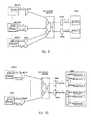
- the PON system based on wavelength protection in Figure 9supports power distribution PON, which is substantially the same as the system in figure 6 , wherein ⁇ 1 and ⁇ 3 are downlink active and backup wavelengths, and ⁇ 2 and ⁇ 4 are uplink active and backup wavelengths.
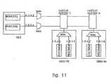
- FIG. 11Another embodiment in the present invention is a PON that supports WDM.
- a WDM PON system based on wavelength protectionis shown, wherein, in the downlink direction, there is an active wavelength and a backup wavelength in which ⁇ dw is the downlink active wavelength and ⁇ dp is the downlink backup wavelength; however, in the uplink direction, each ONU employs an active wavelength and a backup wavelength, wherein ⁇ w1: n (expressing ⁇ w1, ⁇ w2... ⁇ wn) is the uplink active wavelength and ⁇ p1: n (expressing ⁇ p1, ⁇ p2... ⁇ pn) is the uplink backup wavelength.
- the wavelengths of uplink optical signals sent by each ONUare different, and after the interface circuits of OLTs receive these signals with different wavelengths, they will distinguish them with WDM device and then process them individually.
- the present inventiononly needs to add several WDM devices to realize wavelength-based protection, and the location of the WDM devices is the same as in the figure 6 and will not be described further.
- the two WDM devices that are connected with the trunk fibers in the uplink directionmust pass one waveband, in other words, one must pass wavelength of ⁇ w1: n, and the other must pass wavelength of ⁇ p1: n.
- the PON system based on wavelength protectionhas nothing to do with topology structure and it can support various topology structures.
- the figure 9 and 10both belong to tree-structure PON system based on wavelength protection.
- a PON system with bus topology structure based on wavelength protectionis used, as shown in figure 11 , and the multiple optical splitters on the trunk fiber are inter-connected through buses.
- the basic principlesare the same, as long as the optical splitter network constructed by these optical splitters can distribute the optical signals sent in from trunk fiber port to each branch fiber port at a certain optical power ratio, and the optical signals sent in reversely from each branch fiber port are super-positioned first and are then output from the trunk fiber port at a certain ratio.
- the PON system based on wavelength protectioncan also employ ring topology.
- the present inventioncan be applied in various PON protection systems and provide hot backup protection for trunk fiber and OLT, therefore it can meet the demand of 50ms at telecommunication level and significantly reduce the quantity of branch fibers and its cabling cost, and is particularly suitable for the protection of common family users.
Landscapes
- Engineering & Computer Science (AREA)
- Computer Networks & Wireless Communication (AREA)
- Signal Processing (AREA)
- Physics & Mathematics (AREA)
- Electromagnetism (AREA)
- Computing Systems (AREA)
- Optical Communication System (AREA)
Description
- The present invention pertains to a network protection system, especially to a network protection system of a passive optical network (PON) system and a protection backup method thereof.
- As shown in
figure 1 , a PON communication system comprises the following parts: an optical line terminal (OLT) C01, a trunk optical fiber C02, an optical splitter network C03, an optical network unit (ONU) C04 and a branch optical fiber C05. The trunk optical fiber C02, the optical splitter network C03 and the branch optical fiber C05 are collectively referred to an optical distribution network (ODN) which is a passive system, therefore, any network with this kind of architecture is named as passive optical network (PON). - PON communication system supports multi-service transmission and needs to provide reliability at a telecommunication level, and protection switching is its important content. ITU G.984 series and G.983 series define four protection methods of a PON system. The system structure shown in
figure 2 only targets for optical fiber backup and only supports cold backup; the system structure shown infigure 3 only targets for OLT backup and only supports cold backup; what is shown infigure 5 is the system structure for half-backup, providing end-to-end protection in cold backup, as well as the trunk optical fiber and the OPT interface circuit protection in cold backup. The protection types offered in the above three system structures are all cold backups and need new distance measurement and registration after the active and backup systems perform protection switching, and its protection switching speed can not meet the telecommunication level requirement of 50ms. Figure 4 shows a system structure of full backup, providing end-to-end protection of the ONU, the interface circuits of OLT and the optical fiber links (including trunk fiber and branch fiber) between them. This type of protection is hot backup and does not need new distance measurement and registration after protection switching, therefore it is able to offer 50ms protection switching at telecommunication level. The standard G.983 specifically describes and regulates the protection mechanism infigure 4 .- Everything in the full backup system in
figure 4 is doubled: two OLT interface circuits, two trunk fibers, two optical splitters, two branch fibers, and the ONU with two interface circuits, therefore the cost is high and it is only suitable for the optical fiber-to-resident corporation users or enterprise users with high demand for reliability, and it is not suitable for public users who are more sensitive with price. In this system, if only one branch optical fiber is set between the optical splitter and the ONU, such as the connection to ONU 1 in the figure, then there will be no protection for the users of this unit. - When the PON is applied in the optical fiber-to-the-home (FTTH) project for public user, the damage of one branch fiber only impacts the single user that is connected with that branch fiber while no one else will be affected, however, when the trunk fiber or OLT is damaged, the entire PON will be paralyzed. Therefore, considering feasibility, reliability and performance, when PON is used for broad public users, it needs to provide the protection time of 50ms, but branch optical fiber belongs to single users and no protection is needed. Because the optical splitter in the public parts is passive and is placed in the boxes and small rooms with guard, the reliability is high and no backup is needed, in other words, the protection part is only designed for trunk fiber and OLT in public parts. There are only two protection types offered in
figure 4 , either full-link end-to-end protection, or no protection at all, which can not meet the protection demand of public users. - The technical problem that needs to be solved in present invention is to provide a passive optical network system based on wavelength protection. The cost is relative low and moreover, it can provide hot backup protection for the trunk fiber and OLT.
- In order to solve the above technology problem, the present invention provides a passive optical network system based on wavelength protection, which comprises an OLT that includes a first interface circuit A and a second interface circuit B, a first trunk fiber and a second trunk fiber, an optical splitter network that is connected with the first and the second trunk fibers, branch fibers that are connected with the optical splitter network, and multiple ONUs P that include the first interface circuits A' and the second interface circuits B', wherein it further comprises:
- a first WDM (wave division multiplexing) device, in which one end is connected with the first trunk fiber while the other end is connected with the first interface circuit A through a first interface optical fiber;
- a second WDM device, in which one end is connected with the second trunk fiber while the other end is connected with the second interface circuit B through a second interface optical fiber; and
- multiple WDM devices at unit side, in which one end in each device is connected with one branch fiber and the other one is connected with the first interface circuit A' and the second interface circuit B' of one ONU P respectively through two unit interface optical fibers;
- Said first interface circuit A is used to transmit downlink optical signal DA, the second interface circuit B is used to transmit downlink optical signal DB, the wavelengths of DA and DB being different; said first interface circuit A' is used to transmit uplink optical signal UA, the second interface circuit B' is used to transmit uplink optical signal UB, the wavelengths of UA and UB being different;
- Said first WDM device can pass through the downlink optical signal DA and the uplink optical signal UA, but refuses the uplink optical signal UB; said second WDM device can pass the downlink optical signal DB and the uplink optical signal UB, but refuses the uplink optical signal UA;
- Said optical splitter network is used to distribute the optical power of the downlink optical signals sent in by the two trunk fiber ports to each branch fiber port; the optical signals sent in by each branch fiber port are superimposed first and then output through trunk fiber ports;
- Said WDM device at unit side can respectively pass the downlink optical signals DA and DB that are transmitted by the branch fibers connected with it to the first interface circuit A' and the second interface circuit B' of the corresponding ONU P, and will pass the uplink optical signals that are transmitted by these two interface circuits to said branch fiber.
- Additionally, the PON system also possesses the following characteristics: it further comprises several ONUs P' that include the first interface circuits A' and the second interface circuits B', the first interface circuit A' and the second interface circuit B' of this ONU are successively connected to said optical splitter network through a unit interface optical fiber, a WDM device at unit side and a branch fiber respectively, wherein the WDM device at unit side that is connected with the first interface circuit A' can pass the downlink optical signal DA and the uplink optical signal UA, but refuses the downlink optical signal DB; the WDM device at unit side that is connected with the second interface circuit B' can pass the downlink optical signal DB and the uplink optical signal UB, but refuses the downlink optical signal DA.
- Additionally, said PON system also possesses the following characteristics: it comprises several ONUs P" that include the first interface circuits A', the first interface circuit A' of this ONU P" is successively connected to said optical splitter network through a unit interface optical fiber, a WDM device at unit side and a branch fiber. The WDM device at unit side can pass the downlink optical signal DA and the uplink optical signal UA, but refuses the downlink optical signal DB.
- Additionally, said PON system also possesses the following characteristic: said optical splitter network is composed of an optical splitter of N:2.
- Additionally, said PON system also possesses the following characteristics: said optical splitter network is composed of two optical splitters of 2:1 and two splitters of N:2, wherein the two outputs of each optical splitter of 2:1 are connected to the input ends of said two optical splitters of N:2.
- Additionally, said PON system also possesses the following characteristic: the topology of the PON system is tree topology, bus topology, ring topology or a combination thereof.
- Additionally, said PON system also possesses the following characteristics: the system is a PON system of WDM, in which the wavelengths of the uplink signals UA transmitted by the first interface circuit A' in each ONU are different from each other, so are the wavelengths of the uplink signals UB transmitted by the second interface circuit B'. However the band in which uplink optical signal UA resides does not overlap the band in which uplink optical signal UB resides. The first WDM device can only pass the signals of the band in which uplink optical signal UA resides in uplink direction; the second WDM device can only pass through the signals of the band in which uplink optical signal UB resides in uplink direction.
- Another technical problem that needs to be solved in present invention is to provide a protection backup method of PON system based on wavelength protection. The cost needed for realizing the protection in this method is relative low, and the method can provide a hot backup protection for the trunk fiber and the OLT.
- In order to solve the above technical problem, the present invention provides a protection backup method of PON system based on wavelength protection, which comprises the following steps:
- When operating properly, in the downlink direction, the interface circuits A and B of the OLT respectively transmit downlink optical signals DA and DB with different wavelengths. These two optical signals will proceed for optical power distribution after being transmitted to the optical splitter network through individual trunk line, so that there are downlink optical signals DA and DB within each branch fiber. Then by utilizing the WDM device on the branch line, the optical signal UA in the branch fiber is only passed to the interface circuit A of the ONU and the optical signal UB is only passed to the interface circuit B of the ONU;
- In the uplink direction, the interface circuits A and B of the OLT will respectively transmit uplink optical signals UA and UB with different wavelengths; these two optical signals will first be transmitted to optical splitter network through the branch lines and then be transmitted to the two trunk lines. Then by utilizing the WDM device in the trunk line, the optical signal UA is only passed to the interface circuit A of the OLT and the optical signal UB is only passed to the interface circuit B of the OLT;
- As a result, active/backup bidirectional optical paths are formed between the interface circuits A of said OLT and ONU and between the interface circuits B of said OLT and the ONU. The active/backup bidirectional optical paths independently perform registration, distance measurement and dynamic adjustments of the bandwidth, therefore when the active bidirectional optical path is out of work, the service will directly be switched to the backup bidirectional optical path.
- Additionally, said protection backup method also possesses the following characteristic: said active/backup bidirectional optical paths are configured with load sharing mode and the service is transmitted at the same time in the both active/backup optical paths.
- Additionally, said protection backup method also possesses the following characteristic: when the system is a PON system of WDM, the WDM device of the trunk line is set in such a way that it can pass the signals of one band in the uplink direction.
- In conclusion, compared with other PON protection systems, the PON system based on wavelength protection has the following characteristics and advantages:
- (1) The intermediate reliability protection only protects the trunk fiber and the OLT and can meet the demand of telecommunication level of 50ms. Furthermore, each ONU only needs to be distributed with one branch optical fiber, which significantly reduces the quantity and cabling cost of branch fibers, therefore resulting in a lower cost. As for the common family users, the reliability is good enough, and therefore it is an economical protection type.
- (2) it is capable of realizing multiple protection types, including high reliability protection and intermediate reliability protection, both of which can both meet the telecommunication level demand of 50ms, and meanwhile protection switching will not lead to the interruption of user service. Wherein, the high reliability protection can provide end-to-end full link protection, and it is for sure that the PON system based on wavelength protection also supports non-protection type.
- (3) The PON system based on wavelength protection also supports various types of optical splitter networks.
- (4) The PON system based on wavelength protection also supports topologies such as tree, bus, ring and the like, and meanwhile it also supports various PON technologies such as APON, EPON, GPON and WDM PON, etc..
- (5) The system can be set in load sharing mode. The active/backup optical paths will transmit service at the same time, resulting in an increase in the system bandwidth.
Figure 1 is a schematic diagram of PON system.Figure 2 is a structural diagram of the optical fiber backup system, which only supports cold backup.Figure 3 is a structural diagram of OLT backup system only, which only supports cold backup.Figure 4 is a structural diagram of the full backup system, which provides end-to-end protection and supports hot backup.Figure 5 is a structural diagram of the half backup system, which provides end-to-end protection of cold backup and the trunk fiber as well as OLT interface circuit protection of cold backup.Figure 6 is a structural diagram of PON protection switching based on wavelength in one embodiment of the present invention.Figure 7 is a schematic diagram of the optical splitter network constructed by a single optical splitter ofN:2.Figure 8 is a schematic diagram of net optical splitter network that is constructed by double optical splitters of 2: 1 and double optical splitters of N:2.Figure 9 is a power distribution PON system based on wavelength protection in one embodiment of the present invention.Figure 10 is a WDM PON system based on wavelength protection in another embodiment of the present invention.Figure 11 is a PON system based on wavelength protection in another embodiment of the present invention, which employs bus topology network.- In the diagrams, WDM represents wavelength division multiplexing device, PONLT (1) represents
interface circuit 1, PONLT (0) representsinterface circuit 0. Figure 6 shows the system structure in one embodiment of the present invention. In order to support wavelength-based protection, the OLT C1 must comprises two of active/backup interface circuits, which infigure 6 areinterface circuit 1 andinterface circuit 0. The two interface circuits of OLT C1 are respectively connected to the WDM devices C9 and C8 at the terminal side through terminal interface optical fibers C12 and C13. On the other hand, WDM devices C9 and C8 are respectively connected to the optical splitter network C3 through trunk fibers C2 and C14. The optical splitter network C3 can connect with multiple branch fibers at the same time; wherein the branch fibers C10, C16, and C 15 are respectively connected with WDM devices at unit side C4, C11 and C7. The connection between the WDM device at unit side and the interface circuit of ONU is realized through the unit interface optical fiber; wherein, the two ends of unit interface optical fiber C17 are respectively connected to WDM device C4 and theinterface circuit 1 of ONU C5, the two ends of unit interface optical fiber C19 are respectively connected to WDM device C11 and theinterface circuit 0 of ONU C5; while the two ends of unit interface optical fiber C20 are respectively connected to WDM device C7 and theinterface circuit 1 of ONU C6, the two ends of unit interface optical fiber C18 are respectively connected to WDM device C7 and theinterface circuit 0 of ONU C6. In the text, the part including WDM device between optical splitter network and ONU is named as branch line, and the part including WDM device between optical splitter network and OLT is named as trunk line.- In the system, the
interface circuit 1 andinterface circuit 0 ofOLT C 1 respectively send downlink optical signals with wavelengths of λ1 and λ3, while theinterface circuit 1 andinterface circuit 0 of each ONU respectively send uplink optical signals with wavelengths of λ2 and λ4, wherein λ1 ≠λ3, λ2≠λ4. - The WDM devices C9 and C4 support the optical signals with wavelengths of λ1 and λ2 to pass through, but refuse the signals with wavelengths of λ3 and λ4; the WDM devices C8 and C11 support the optical signals with wavelengths of λ3 and λ4 to pass through, but refuse the signals with wavelengths of λ1 and λ2. While in the downlink direction (from line end to network unit), the WDM device C7 passes the optical signal with wavelength of λ1 to the port that is connected with the unit interface optical fiber C20 and passes the optical signal with wavelength of λ3 to the port that is connected with the unit interface optical fiber C18; in the uplink direction, the device can pass the optical signals with wavelengths of λ2 and λ4 that are transmitted to said two ports to the branch fiber C15, and can realize the isolation between the two ports.
- The optical splitter network C3 is a multiple-port optical power distribution network that is constructed by one or more optical splitters. In the present embodiment, it comprises two trunk fiber ports and multiple branch fiber ports, for the optical signals that are sent in from the trunk fiber port, the optical power is distributed to each branch fiber port with a certain ratio (the ratio of the optical signal power that is sent out by each branch fiber can be arbitrary). The optical signals that are sent in from each branch fiber port in reverse direction are super-positioned and then are sent out from the trunk fiber port at a certain ratio (usually equally distributing the optical power at a ration of 1:1). The optical splitter network has nothing to do with the wavelength and in the present embodiment, said optical splitter network is implemented by employing an optical splitter of N:2, as shown in
figure 7 . However the invention is not limited to that. - The
interface circuit 1 of OLT C1 sends the optical signal with wavelength of λ1 to the terminal interface optical fiber C12. The optical signal with this wavelength is then sent to the WDM device C9 through interface optical fiber C12. Since C9 supports the optical signal with wavelength of λ1 to pass through, the optical signal with wavelength of λ1 can then be transmitted to trunk fiber C2 through device C9, and C2 transmits the λ1 optical signal to the optical splitter network C3, C3 distributes the λ1 optical signal at a certain power ratio to all the branch fibers, including C10, C16 and C 15. These branch fibers C10, C16 and C15 respectively transmit the λ1 optical signal to the WDM devices C4, C11 and C7 connected with each branch fiber. The WDM device C4 passes the λ1 optical signal to the interface optical fiber C17 and furthermore sends the signal to theinterface circuit 1 of ONU C5. While the WDM device C11 filters out the λ1 optical signal without passing the signal to theinterface circuit 0 of ONU C5 through the interface optical fiber C19, the WDM device C7 passes the λ1 optical signal to the interface optical fiber C20 and furthermore sends the signal to theinterface circuit 1 of ONU C6, while the WDM device C7 does not pass the λ1 optical signal to the interface optical fiber C18, therefore the λ1 optical signal can not be transmitted to theinterface circuit 0 of ONU C6. As a result, a communication path with wavelength of λ1 is set up between theinterface circuit 1 of OLT C1 and theinterface circuits 1 of ONU C5 and ONU C6, which is called downlink λ1 optical path. - The operation transmission wavelengths of
interface circuits 1 in ONU C5 and C6 are both of λ2; these two interface circuits can not send optical signals at the same time, but transmit in turn by employing TDMA mechanism. The λ2 optical signals sent byinterface circuits 1 in both C5 and C6 are transmitted to WDM devices C4 and C7 through unit interface optical fibers C20 and C17. Because there is a great isolation between interfaces of C20 and C18 of WDM device C7, the λ2 optical signal will not be sent to the interface optical fiber C18, while the WDM device C7 can pass the λ2 optical signal to the branch fiber C15, and further to the optical splitter network C3. The WDM device C4 can pass the λ2 optical signal to the branch fiber C10, and further to the optical splitter network. The optical splitter network will not transmit the λ2 optical signal to the branch fiber C16, but can pass it to the trunk fiber C2 and C14 at the same time, and further respectively to the WDM devices C9 and C8. Due to the filtering function of C8 for λ2 optical signal, the λ2 optical signal can not be transmitted to theinterface circuit 0 of the OLT C1, while C9 has a passing function for λ2 optical signal, therefore, the λ2 signal is transmitted to the terminal interface optical fiber C12 and further to theinterface circuit 1 of OLT C1. As a result, an optical communication path with wavelength of λ2 is set up between theinterface circuit 1 of OLT C1 and theinterface circuits 1 of ONUs C5 and C6, which is called uplink λ2 optical path. - In this way, a bidirectional communication optical path is formed between the
interface circuits 1 of OLT and ONU, wherein, the uplink wavelength of the optical path is of λ2, and the downlink wavelength is of λ1. - The
interface circuit 0 of OLT C1 sends the optical signal with wavelength of λ3 to the terminal interface optical fiber C13. The optical signal with this wavelength was then sent to the WDM device C8 through interface optical fiber C13. Since C8 supports the optical signal with wavelength of λ3 to pass through, the optical signal with wavelength of λ3 can then be transmitted to trunk fiber C14 by device C8. C14 transmits the λ3 optical signal to the optical splitter network C3, C3 distributes the signal at a certain power ratio to all the branch fibers, including C10, C16 and C15. These branch fibers C10, C16 and C 15 respectively transmit the λ3 optical signal to the WDM devices C4, C11 and C7 connected with them individually. The WDM device C4 filters out the λ3 optical signal, and the signal is not sent to the interface optical fiber C17, therefore, the λ3 optical signal will not be transmitted to theinterface circuit 1 of the ONU C5. The WDM device C11 passes the λ3 optical signal to the interface optical fiber C 19 and further to theinterface circuit 0 of ONU C5. While, the WDM device C7 does not pass the λ3 optical signal to the interface optical fiber C20, therefore the λ1 optical signal can not be transmitted to theinterface circuit 1 of ONU C6. On the other hand, the WDM device C7 can pass the λ3 optical signal to the interface optical fiber C18, and further to theinterface circuit 0 of ONU C6. As a result, a communication path with wavelength of λ3 is set up between theinterface circuit 0 of OLT C1 and theinterface circuits 0 of ONU C5 and ONU C6, which is called downlink λ3 optical path. - The operation transmission wavelengths of
interface circuits 0 in ONU C5 and C6 are both of λ4; these two interface circuits can not send optical signals at the same time, but transmit in turn by employing TDMA mechanism. The λ4 optical signals sent out byinterface circuits 0 in both C5 and C6 are transmitted to WDM devices C11 and C7 through unit interface optical fibers C18 and C19. Because there is a great isolation between interfaces of C20 and C18 of WDM device C7, the λ4 optical signal will not be sent to the interface optical fiber C20, while the WDM device C7 can pass the λ4 optical signal to the branch fiber C15, and further to the optical splitter network C3. The WDM device C11 can pass the λ4 optical signal to the branch fiber C16, and further to the optical splitter network C3. The optical splitter network will not transmit the λ4 optical signal to the branch fiber C10, but can pass it to the trunk fibers C2 and C14 at the same time, and further to the WDM devices C9 and C8 respectively. Due to the filtering function of C9 for λ4 optical signal, the λ4 optical signal can not be transmitted to theinterface circuit 1 of the OLT C1; one the other hand, C8 has a passing function for λ4 optical signal, therefore, the λ4 optical signal is transmitted to the terminal interface optical fiber C 13 and further to theinterface circuit 0 of OLT C1. As a result, an optical communication path with wavelength of λ4 is set up between theinterface circuit 0 of OLT C1 and theinterface circuits 0 of ONUs C5 and C6, which is called uplink λ4 optical path. - Thus, a bidirectional communication optical path is formed between the
interface circuits 0 of OLT and ONU, wherein, the uplink wavelength of the optical path is of λ4, and the downlink wavelength is of λ3. - From above analysis, it can be seen that by using WDM technology, two independent bidirectional communication optical paths can be formed between the OLT and ONU, wherein the
interface 1 uses the first bidirectional optical path with wavelengths of λ1 and λ2, while theinterface 0 uses the second bidirectional optical path with wavelengths of λ3 and λ4. The two bidirectional optical paths can work at the same time and form the active/backup communication paths of hot backup for each other. If the configuration service is transmitted through the first bidirectional optical path, the first path is the active communication path and the second bidirectional optical path can be set as the backup communication path for the first path. When there is a malfunction with the first bidirectional optical communication path, the service can be switched to the second bidirectional optical communication path, which will continue transmission, and thus the service can be protected, and will not be disconnected and fail in transmission due to the malfunction of the first bidirectional optical path. Since the hot backup method is employed, the two active/backup bidirectional optical paths can independently perform registration, distance measurement and bandwidth dynamic adjustment, therefore when the active bidirectional optical path malfunctions, the service will be switched to the backup bidirectional optical path, and after the protection switching, the ONU of the PON doesn't need to register over again and the OLT doesn't need to perform distance measurement for ONU, thus ensuring the time for protection switching, which can be limited to within 50ms required by telecommunication level. - Besides, the system can also be configured in load sharing mode, in which the service is transmitted through active and backup paths at the same time, resulting in the increase of system bandwidth.
- In the embodiment of
figure 6 , there actually exist two kinds of branch structures (referring to the connection structure from the optical splitter network to each ONU) between ONU and optical splitter network. It is a hybrid structure and provides many optional protection mechanisms, wherein: - There are two branch fibers C10 and C16 between ONU C5 and optical splitter network C3, therefore the ONU C5 can provide end-to-end hot backup protection of service, and no matter whether there is something wrong with the trunk fiber, branch fiber or the interface circuit of OLT and ONU, the service can always be protected with high reliability. However, since the interface circuit of the OLT and ONU, the trunk fiber, the branch fiber and the interface fiber all need to be doubled, the cost is high.
- There is only one branch fiber C15 between ONU C6 and the optical splitter network C3, and in the meantime, C6 is configured with unit interface optical fiber C20, C18 and
interface circuit - In another embodiment of the present invention, the part between ONU and optical splitter network in PON system only employs the branch structure that is used between the ONU C6 and optical splitter network C3 in
figure 6 , thereby, providing intermediate reliable protection for each ONU. - In another embodiment of the present invention, the optical splitter network in
figure 6 employs the net-like optical splitter network that is constructed by two optical splitters of 2: 1 and two optical splitters of N:2 shown infigure 8 . The two outputs of each optical splitter of 2:1 are both connected with the inputs of the two optical splitters of 2:1 and all the optical splitters are in working state. By utilizing said splitter network, it can provide hot backup protection when a certain splitter is out of work, thereby increasing the reliability of the protection. - In another embodiment of present invention, if the situation is sensible to cost but has no demand on reliability, when the
interface circuit 1 and interface fiber C20 of ONU C6 are not configured, the ONU C6 then becomes an ONU without protection, which can be referenced to theONU # 1 infigure 9 . The branch structure with no protection, the branch structure providing intermediate reliability and the branch structure providing high reliability in the invention can be combined arbitrarily. - The PON system based on wavelength protection in
Figure 9 supports power distribution PON, which is substantially the same as the system infigure 6 , wherein λ1 and λ3 are downlink active and backup wavelengths, and λ2 and λ4 are uplink active and backup wavelengths. - Another embodiment in the present invention is a PON that supports WDM. In
figure 11 , a WDM PON system based on wavelength protection is shown, wherein, in the downlink direction, there is an active wavelength and a backup wavelength in which λdw is the downlink active wavelength and λdp is the downlink backup wavelength; however, in the uplink direction, each ONU employs an active wavelength and a backup wavelength, wherein λw1: n (expressing λw1, λw2...λwn) is the uplink active wavelength and λp1: n (expressing λp1, λp2...λpn) is the uplink backup wavelength. - In the WDM PON system, the wavelengths of uplink optical signals sent by each ONU are different, and after the interface circuits of OLTs receive these signals with different wavelengths, they will distinguish them with WDM device and then process them individually. Based on the current WDM PON system, the present invention only needs to add several WDM devices to realize wavelength-based protection, and the location of the WDM devices is the same as in the
figure 6 and will not be described further. However, what is different fromfigure 6 embodiment is that the two WDM devices that are connected with the trunk fibers in the uplink direction must pass one waveband, in other words, one must pass wavelength of λw1: n, and the other must pass wavelength of λp1: n. - Besides, the PON system based on wavelength protection has nothing to do with topology structure and it can support various topology structures. The
figure 9 and 10 both belong to tree-structure PON system based on wavelength protection. In another embodiment in the present invention, a PON system with bus topology structure based on wavelength protection is used, as shown infigure 11 , and the multiple optical splitters on the trunk fiber are inter-connected through buses. However, the basic principles are the same, as long as the optical splitter network constructed by these optical splitters can distribute the optical signals sent in from trunk fiber port to each branch fiber port at a certain optical power ratio, and the optical signals sent in reversely from each branch fiber port are super-positioned first and are then output from the trunk fiber port at a certain ratio. In another embodiment of the present invention, the PON system based on wavelength protection can also employ ring topology. - The present invention can be applied in various PON protection systems and provide hot backup protection for trunk fiber and OLT, therefore it can meet the demand of 50ms at telecommunication level and significantly reduce the quantity of branch fibers and its cabling cost, and is particularly suitable for the protection of common family users.
Claims (11)
- A passive optical network PON system based on wavelength protection, comprising an Optical line terminal (OLT) that includes a first interface circuit A (C1:int.1) and a second interface circuit B (C1: int.0), a first trunk fiber (C2) and a second trunk fiber (C14), an optical splitter network (C3) that is connected with the first trunk fiber and the second trunk fiber, branch fibers that are connected with the optical splitter network, and multiple Optical network units (ONUs) P that include first interface circuits A' (C5 or C6: int.1) and second interface circuits B'(C5 or C6: int.0),characterized in that the passive optical network further comprises:a first WDM device (C9), one end of which being connected with the first trunk fiber (C2), and other end being connected with the first interface circuit A (C1:int.1) through a first interface optical fiber (C12);a second WDM device (C8), one end of which being connected with the second trunk optical fiber (C 14), and the other end being connected with the second interface circuit B (C1: int.0) through a second interface optical fiber (C13); andmultiple WDM devices (C4, C11) at Optical network unit side, one end of each being connected with one branch fiber (C10, C16), and the other end being respectively connected with the first interface circuit A' (C5: int.1) and the second interface circuit B' (C5: int.0) of one ONU P through two unit interface optical fibers (C17, C19);said first interface circuit A (C1:int.1) is adapted to transmit a downlink optical signal DA(λ1); the second interface circuit B (C1:int.0) is adapted to transmit a downlink optical signal DB(λ 3), wherein wavelengths of DA and DB are different (λ 1 # λ 3); said first interface circuit A' is adapted to transmit an uplink optical signal UA(λ2); the second interface circuit B' is adapted to transmit an uplink optical signal UB(λ4), wherein wavelengths of UA and UB are different (λ2 ≠ λ4);said first WDM device (C9) is adapted to pass the downlink optical signal DA(λ 1) and the uplink optical signal UA(λ 2), and refuse the uplink optical signal UB(λ 4), while said second WDM device (C8)is adapted to pass the downlink optical signal DB (λ3) and the uplink optical signal UB(λ4), and refuse the uplink optical signal UA (λ2);said optical splitter network (C3) is adapted to distribute optical power of downlink optical signals sent in through ports of the two trunk fibers to each port of the branch fiber, and optical signals sent in through each port of the branch fiber are super-positioned first and then output from ports of the trunk fibers;said WDM device (C4, C11) at Optical network unit side is adapted to respectively pass the downlink optical signals DA(λ1) and DB(λ3) that are transmitted by the branch fiber connected with it to the first interface circuit A' (C5: int.1) and second interface circuit B' (C5: int.0) of corresponding ONU P, and pass the uplink optical signals (λ 2 or λ 4) that are transmitted by the two interface circuits to said branch fiber.
- The PON system in claim 1,characterized in that it further comprises several ONUs P' that include the first interface circuits A' and the second interface circuits B', the first interface circuit A' (C6: int.1) and the second interface circuit B' (C6: int.0) in the ONU are successively connected to said optical splitter network through a unit interface optical fiber (C18, C20), a WDM device (C7) at Optical network unit side and a branch fiber, wherein the WDM device at Optical network unit side that is connected with the first interface circuit A' (C6: int.1) is adapted to pass the downlink optical signal DA(λ1) and the uplink optical signal UA(λ 2), and refuse the downlink optical signal DB(λ 3), while the WDM device at Optical network unit side that is connected with the second interface circuit B' is adapted to pass the downlink optical signal DB(λ 3) and the uplink optical signal UB(λ 4), and refuse the downlink optical signal DA(λ1).
- The PON system in claim 1,characterized in that it also comprises several ONUs P" that include the first interface circuits A', the first interface circuit A' of the ONU P" is successively connected to said optical splitter network through a unit interface optical fiber, a WDM device at unit side and a branch fiber, wherein the WDM device at unit side can pass the downlink optical signal DA and the uplink optical signal UA, but refuses the downlink optical signal DB.
- The PON system in claim 1, 2 or 3, wherein said optical splitter network is composed of an optical splitter of N:2.
- The PON system in claim 1, 2 or 3, wherein said optical splitter network is composed of two optical splitters of 2:1 and two optical splitters of N:2, and two outputs of each optical splitter of 2:1 are connected to inputs of the two optical splitters ofN:2.
- The PON system in claim 1, 2 or 3, wherein topology of the PON system is tree topology, bus topology, ring topology or a combination thereof.
- The PON system in claim 1, 2 or 3, wherein the system is the PON system of WDM, in which wavelengths of the uplink signals UA that are transmitted by the first interface circuit A' in each ONU are different from each other, and wavelengths of the uplink signals UB that are transmitted by the second interface circuit B' are also different from each other, but a band in which uplink optical signal UA resides does not overlap a band in which uplink optical signal UB resides, the first WDM device can only pass signals of the band in which uplink optical signal UA resides in uplink direction, and the second WDM device can only pass signals of the band in which uplink optical signal UB resides in uplink direction.
- A protection backup method of a PON system based on wavelength protection, comprising the following steps:when in normal operation, in downlink direction, the interface circuits A and B of the OLT will respectively transmit downlink optical signals DA and DB with different wavelengths, these two optical signals will proceed for optical power distribution after being transmitted to the optical splitter network through individual trunk line, so that within each branch fiber there exists the downlink optical signals DA and DB, then by utilizing the WDM device on branch line, only the optical signal UA in the branch fiber is passed to the interface circuit A of the ONU and only the optical signal UB is passed to the interface circuit B of the ONU;in uplink direction, the interface circuits A and B of the OLT will respectively transmit uplink optical signals UA and UB with different wavelengths, these two optical signals will first be transmitted to the optical splitter network through the branch lines and then be transmitted to the two trunk lines, then by utilizing the WDM device on the trunk line, only the optical signal UA is passed to the interface circuit A of the OLT and only the optical signal UB is passed to the interface circuit B of the OLT;as a result, two bidirectional optical paths are formed with one being active and the other being backup between the interface circuits A and between the interface circuits B of said OLT and said ONU, the two active/backup bidirectional optical paths independently perform registration, distance measurement and dynamic adjustment of bandwidth, and when the active bidirectional optical path is out of work, it will directly switch the service to the backup bidirectional optical path.
- The protection backup method in claim 8, wherein said active/backup bidirectional optical paths are set in load sharing mode and transmit services at the same time in the active/backup optical paths.
- The protection backup method in claim 8, wherein when the system is the PON system of WDM, the WDM device of the trunk line is set to pass signals of one band in uplink direction.
- The protection backup method in claim 8, wherein said protection backup method has nothing to do with link layer technology of PON and it can be used in power PON such as APON, EPON and GPON, and the like.
Applications Claiming Priority (1)
| Application Number | Priority Date | Filing Date | Title |
|---|---|---|---|
| PCT/CN2005/000601WO2006116895A1 (en) | 2005-04-29 | 2005-04-29 | Passive optical network system based on wavelength protection and protecting backup method thereof |
Publications (3)
| Publication Number | Publication Date |
|---|---|
| EP1876736A1 EP1876736A1 (en) | 2008-01-09 |
| EP1876736A4 EP1876736A4 (en) | 2013-10-09 |
| EP1876736B1true EP1876736B1 (en) | 2015-06-10 |
Family
ID=37307579
Family Applications (1)
| Application Number | Title | Priority Date | Filing Date |
|---|---|---|---|
| EP05743329.4AExpired - LifetimeEP1876736B1 (en) | 2005-04-29 | 2005-04-29 | Passive optical network system based on wavelength protection and protecting backup method thereof |
Country Status (4)
| Country | Link |
|---|---|
| US (1) | US7634160B2 (en) |
| EP (1) | EP1876736B1 (en) |
| CN (1) | CN101167274B (en) |
| WO (1) | WO2006116895A1 (en) |
Families Citing this family (38)
| Publication number | Priority date | Publication date | Assignee | Title |
|---|---|---|---|---|
| KR100833504B1 (en)* | 2006-12-05 | 2008-05-29 | 한국전자통신연구원 | PON partial double protection switching device and method using single splitter |
| JP4340692B2 (en)* | 2007-02-02 | 2009-10-07 | 株式会社日立コミュニケーションテクノロジー | Passive optical network system and operation method thereof |
| CN101399614B (en)* | 2007-09-26 | 2012-10-03 | 华为技术有限公司 | Protection method, system and device for long distance passive optical network |
| EP2056619A1 (en)* | 2007-11-05 | 2009-05-06 | British Telecmmunications public limited campany | Passive optical network |
| EP2086136A1 (en)* | 2008-01-29 | 2009-08-05 | British Telecommunications Public Limited Company | Optical communication |
| WO2009116904A1 (en)* | 2008-03-17 | 2009-09-24 | Telefonaktiebolaget L M Ericsson (Publ) | Immediate protection scheme for passive optical network |
| AU2008353014B2 (en)* | 2008-03-17 | 2013-09-12 | Telefonaktiebolaget L M Ericsson (Publ) | Fast protection scheme for passive optical network |
| EP2320607A4 (en)* | 2008-08-26 | 2016-05-11 | Mitsubishi Electric Corp | PON SYSTEM AND REDUNDANCY METHOD |
| US8626954B2 (en)* | 2008-08-28 | 2014-01-07 | Alcatel Lucent | Application-aware M:N hot redundancy for DPI-based application engines |
| US9319758B2 (en)* | 2008-10-21 | 2016-04-19 | Broadcom Corporation | Method and system for protection switching in ethernet passive optical networks |
| WO2010069390A1 (en)* | 2008-12-19 | 2010-06-24 | Nokia Siemens Networks Oy | Method and device for data processing in an udwdm network and communication system comprising such device |
| CN101888268B (en)* | 2009-05-14 | 2013-09-11 | 中兴通讯股份有限公司 | Method and device for realizing backbone optical fiber protection in Ethernet passive optical network |
| CN101902665B (en)* | 2009-05-26 | 2014-05-07 | 华为技术有限公司 | Optical line terminal, optical add-drop multiplexer and optical access system |
| CN101651495A (en)* | 2009-09-25 | 2010-02-17 | 中兴通讯股份有限公司 | Method and device for protecting trunk fibers of wavelength division multiplex (WDM) passive optical network (PON) |
| US8989590B2 (en)* | 2010-01-22 | 2015-03-24 | Broadcom Corporation | Pluggable OLT in Ethernet passive optical networks |
| CN102202244B (en)* | 2010-03-23 | 2014-08-13 | 中兴通讯股份有限公司 | Method and device for improving protective performance of passive optical network |
| CN101841746B (en)* | 2010-04-14 | 2013-07-10 | 东南大学 | Wavelength division multiplexing passive optical network optical line terminal having shared protection function |
| CN101826919B (en)* | 2010-05-11 | 2013-07-31 | 东南大学 | Mixed type passive optical network structure and method for positioning and restoring faults thereof |
| TWI450506B (en)* | 2010-09-20 | 2014-08-21 | Ind Tech Res Inst | Architecture and protection method for passive optical network and structure for optical switch |
| CN101977144B (en)* | 2010-10-20 | 2015-04-01 | 中兴通讯股份有限公司 | Data link protection method and system based on load sharing mode |
| US20130216187A1 (en) | 2011-08-17 | 2013-08-22 | Douglas Ferris Dowling | Distributed passive optical networks |
| CN103220044B (en)* | 2012-01-19 | 2015-12-16 | 中兴通讯股份有限公司 | A kind of optical access network system, Apparatus and method for |
| WO2015041651A1 (en)* | 2013-09-19 | 2015-03-26 | Hewlett-Packard Development Company, L.P. | Software defined optical network |
| CN103475405B (en)* | 2013-09-22 | 2015-11-25 | 四川九州光电子技术有限公司 | A kind of guard method solving long range propagation equipment failure or power-off |
| US9736558B2 (en) | 2014-01-17 | 2017-08-15 | Cisco Technology, Inc. | Optical path fault recovery |
| US10009137B2 (en) | 2014-07-24 | 2018-06-26 | Nippon Telegraph And Telephone Corporation | Optical communication system, station-side device, subscriber device, and optical communication method |
| CN105991182B (en)* | 2015-02-13 | 2020-06-02 | 中兴通讯股份有限公司 | Path protection method and system |
| CN106253971B (en)* | 2015-06-15 | 2020-11-03 | 南京中兴新软件有限责任公司 | Optical network system, optical line terminal, optical network unit and control method thereof |
| US10608735B2 (en)* | 2016-05-04 | 2020-03-31 | Adtran, Inc. | Systems and methods for performing optical line terminal (OLT) failover switches in optical networks |
| WO2017222058A1 (en) | 2016-06-24 | 2017-12-28 | 矢崎総業株式会社 | Vehicle circuit structure |
| US10687678B2 (en) | 2017-06-12 | 2020-06-23 | Emerson Electric Co. | Power systems and methods including a battery charger and safety switch |
| JP7439912B2 (en)* | 2020-04-14 | 2024-02-28 | 日本電信電話株式会社 | Optical communication system and master station equipment |
| CN113644971B (en)* | 2020-05-11 | 2023-04-28 | 华为技术有限公司 | Port detection method and device |
| US11356756B1 (en) | 2021-04-05 | 2022-06-07 | Commonwealth Edison Company | Passive optical network for utility infrastructure resiliency |
| CN115514442A (en)* | 2021-06-22 | 2022-12-23 | 中国电信股份有限公司 | Wavelength division link protection system and method |
| CN113541850B (en)* | 2021-07-20 | 2022-04-26 | 烽火通信科技股份有限公司 | Light splitting device, light splitting device manufacturing method and optical access system |
| US12184401B1 (en)* | 2021-10-15 | 2024-12-31 | Cable Television Laboratories, Inc. | Passive optical tap and associated methods |
| CN119603586B (en)* | 2025-02-06 | 2025-07-22 | 新华三信息技术有限公司 | Data transmission method, device, electronic equipment and FTTR network system |
Family Cites Families (12)
| Publication number | Priority date | Publication date | Assignee | Title |
|---|---|---|---|---|
| US5680235A (en)* | 1995-04-13 | 1997-10-21 | Telefonaktiebolaget Lm Ericsson | Optical multichannel system |
| US5781320A (en)* | 1996-08-23 | 1998-07-14 | Lucent Technologies Inc. | Fiber access architecture for use in telecommunications networks |
| US5986783A (en)* | 1997-02-10 | 1999-11-16 | Optical Networks, Inc. | Method and apparatus for operation, protection, and restoration of heterogeneous optical communication networks |
| US6362908B1 (en)* | 1998-12-02 | 2002-03-26 | Marconi Communications, Inc. | Multi-service adaptable optical network unit |
| JP2001285323A (en)* | 2000-04-03 | 2001-10-12 | Hitachi Ltd | Optical network |
| US6868232B2 (en)* | 2001-02-12 | 2005-03-15 | Lucent Technologies Inc. | Fast protection switching by snooping on upstream signals in an optical network |
| CN100346588C (en)* | 2001-10-29 | 2007-10-31 | 上海贝尔有限公司 | System of dual fibers two-way channel/multiplexing segment rotating loop for wavelength division multiplexing optical network |
| US7085496B2 (en)* | 2002-05-30 | 2006-08-01 | Fujitsu Limited | Passive add/drop amplifier for optical networks and method |
| EP1376918B1 (en)* | 2002-06-24 | 2004-09-29 | Alcatel | Apparatus for a passive optical network |
| CN1221090C (en)* | 2002-07-27 | 2005-09-28 | 华为技术有限公司 | Two-way optical communication apapratus capable of automatically realizing main-backup change |
| US7321729B2 (en)* | 2003-05-29 | 2008-01-22 | Fujitsu Limited | Optical ring network with selective signal regeneration and wavelength conversion |
| KR100547709B1 (en)* | 2003-07-07 | 2006-01-31 | 삼성전자주식회사 | Self-Healing Wavelength Division Multiplexing Passive Optical Subscriber Network |
- 2005
- 2005-04-29EPEP05743329.4Apatent/EP1876736B1/ennot_activeExpired - Lifetime
- 2005-04-29WOPCT/CN2005/000601patent/WO2006116895A1/ennot_activeApplication Discontinuation
- 2005-04-29USUS11/912,973patent/US7634160B2/enactiveActive
- 2005-04-29CNCN2005800495272Apatent/CN101167274B/ennot_activeExpired - Lifetime
Also Published As
| Publication number | Publication date |
|---|---|
| US20080267628A1 (en) | 2008-10-30 |
| EP1876736A4 (en) | 2013-10-09 |
| US7634160B2 (en) | 2009-12-15 |
| EP1876736A1 (en) | 2008-01-09 |
| CN101167274A (en) | 2008-04-23 |
| CN101167274B (en) | 2011-02-16 |
| WO2006116895A1 (en) | 2006-11-09 |
Similar Documents
| Publication | Publication Date | Title |
|---|---|---|
| EP1876736B1 (en) | Passive optical network system based on wavelength protection and protecting backup method thereof | |
| US7340170B2 (en) | Wavelength-division multiplexed self-healing passive optical network | |
| KR100610245B1 (en) | Communication recovery system of wavelength division multiplexing passive optical subscriber network | |
| JP3822897B2 (en) | Optical wavelength multiple access system | |
| US6915075B1 (en) | Protection of WDM-channels | |
| US20060250681A1 (en) | Inter-network optical fiber sharing system | |
| CN101895463B (en) | System and method for achieving network reconfigurability of mixed WDM (Wavelength Division Multiplexing)/TDM (Time Division Multiplexing) PON (Passive Optical Network) | |
| WO2010023721A1 (en) | Pon system and redundancy method | |
| CN102811094B (en) | Protective changeover device of wave division-time division multiplexing passive optical network system and method | |
| US20140050471A1 (en) | Apparatus And Method For Providing Protection In A Passive Optical Network | |
| CN102684810A (en) | Optical network protection method, optical link switching control device and optical link switching control system | |
| CN101841746B (en) | Wavelength division multiplexing passive optical network optical line terminal having shared protection function | |
| US20050276603A1 (en) | Self-monitoring passive optical network | |
| JP2008517529A (en) | Systems and apparatus for telecommunications carrier class WDMPON providing trunk protection with improved fiber usage, distance, and bandwidth | |
| EP1064739B1 (en) | Protection of wdm-channels | |
| JP5727619B2 (en) | System for interconnecting nodes attached to a passive optical network | |
| CN105960769A (en) | Operationally resilient optical network | |
| US20120251097A1 (en) | Passive architectural optical distribution network | |
| CN109818670B (en) | A TWDM-PON system with multi-point fault protection capability | |
| KR100356019B1 (en) | Optical Distribution Network in ATM-PON System | |
| CN101841367A (en) | Optical path switching device having wavelength selection function | |
| CN201608719U (en) | A wavelength division multiplexing passive optical network protection switching device | |
| KR100594902B1 (en) | Ring type optical transmission system | |
| CN202551035U (en) | Optical link switching control apparatus and optical network protection system | |
| US6922530B1 (en) | Method and apparatus for optical channel switching in an optical add/drop multiplexer |
Legal Events
| Date | Code | Title | Description |
|---|---|---|---|
| PUAI | Public reference made under article 153(3) epc to a published international application that has entered the european phase | Free format text:ORIGINAL CODE: 0009012 | |
| 17P | Request for examination filed | Effective date:20071030 | |
| AK | Designated contracting states | Kind code of ref document:A1 Designated state(s):AT BE BG CH CY CZ DE DK EE ES FI FR GB GR HU IE IS IT LI LT LU MC NL PL PT RO SE SI SK TR | |
| DAX | Request for extension of the european patent (deleted) | ||
| REG | Reference to a national code | Ref country code:DE Ref legal event code:R079 Ref document number:602005046741 Country of ref document:DE Free format text:PREVIOUS MAIN CLASS: H04B0010120000 Ipc:H04J0014020000 | |
| A4 | Supplementary search report drawn up and despatched | Effective date:20130909 | |
| RIC1 | Information provided on ipc code assigned before grant | Ipc:H04B 10/032 20130101ALI20130903BHEP Ipc:H04Q 11/00 20060101ALI20130903BHEP Ipc:H04J 14/02 20060101AFI20130903BHEP Ipc:H04B 10/275 20130101ALI20130903BHEP | |
| 17Q | First examination report despatched | Effective date:20140221 | |
| GRAP | Despatch of communication of intention to grant a patent | Free format text:ORIGINAL CODE: EPIDOSNIGR1 | |
| INTG | Intention to grant announced | Effective date:20141219 | |
| GRAS | Grant fee paid | Free format text:ORIGINAL CODE: EPIDOSNIGR3 | |
| GRAA | (expected) grant | Free format text:ORIGINAL CODE: 0009210 | |
| AK | Designated contracting states | Kind code of ref document:B1 Designated state(s):AT BE BG CH CY CZ DE DK EE ES FI FR GB GR HU IE IS IT LI LT LU MC NL PL PT RO SE SI SK TR | |
| REG | Reference to a national code | Ref country code:GB Ref legal event code:FG4D | |
| REG | Reference to a national code | Ref country code:CH Ref legal event code:EP | |
| REG | Reference to a national code | Ref country code:AT Ref legal event code:REF Ref document number:731284 Country of ref document:AT Kind code of ref document:T Effective date:20150715 | |
| REG | Reference to a national code | Ref country code:DE Ref legal event code:R096 Ref document number:602005046741 Country of ref document:DE | |
| REG | Reference to a national code | Ref country code:IE Ref legal event code:FG4D | |
| PG25 | Lapsed in a contracting state [announced via postgrant information from national office to epo] | Ref country code:ES Free format text:LAPSE BECAUSE OF FAILURE TO SUBMIT A TRANSLATION OF THE DESCRIPTION OR TO PAY THE FEE WITHIN THE PRESCRIBED TIME-LIMIT Effective date:20150610 Ref country code:FI Free format text:LAPSE BECAUSE OF FAILURE TO SUBMIT A TRANSLATION OF THE DESCRIPTION OR TO PAY THE FEE WITHIN THE PRESCRIBED TIME-LIMIT Effective date:20150610 Ref country code:LT Free format text:LAPSE BECAUSE OF FAILURE TO SUBMIT A TRANSLATION OF THE DESCRIPTION OR TO PAY THE FEE WITHIN THE PRESCRIBED TIME-LIMIT Effective date:20150610 | |
| REG | Reference to a national code | Ref country code:AT Ref legal event code:MK05 Ref document number:731284 Country of ref document:AT Kind code of ref document:T Effective date:20150610 | |
| REG | Reference to a national code | Ref country code:NL Ref legal event code:MP Effective date:20150610 | |
| PG25 | Lapsed in a contracting state [announced via postgrant information from national office to epo] | Ref country code:BG Free format text:LAPSE BECAUSE OF FAILURE TO SUBMIT A TRANSLATION OF THE DESCRIPTION OR TO PAY THE FEE WITHIN THE PRESCRIBED TIME-LIMIT Effective date:20150910 Ref country code:GR Free format text:LAPSE BECAUSE OF FAILURE TO SUBMIT A TRANSLATION OF THE DESCRIPTION OR TO PAY THE FEE WITHIN THE PRESCRIBED TIME-LIMIT Effective date:20150911 | |
| PG25 | Lapsed in a contracting state [announced via postgrant information from national office to epo] | Ref country code:EE Free format text:LAPSE BECAUSE OF FAILURE TO SUBMIT A TRANSLATION OF THE DESCRIPTION OR TO PAY THE FEE WITHIN THE PRESCRIBED TIME-LIMIT Effective date:20150610 | |
| REG | Reference to a national code | Ref country code:FR Ref legal event code:PLFP Year of fee payment:12 | |
| PG25 | Lapsed in a contracting state [announced via postgrant information from national office to epo] | Ref country code:PT Free format text:LAPSE BECAUSE OF FAILURE TO SUBMIT A TRANSLATION OF THE DESCRIPTION OR TO PAY THE FEE WITHIN THE PRESCRIBED TIME-LIMIT Effective date:20151012 Ref country code:CZ Free format text:LAPSE BECAUSE OF FAILURE TO SUBMIT A TRANSLATION OF THE DESCRIPTION OR TO PAY THE FEE WITHIN THE PRESCRIBED TIME-LIMIT Effective date:20150610 Ref country code:PL Free format text:LAPSE BECAUSE OF FAILURE TO SUBMIT A TRANSLATION OF THE DESCRIPTION OR TO PAY THE FEE WITHIN THE PRESCRIBED TIME-LIMIT Effective date:20150610 Ref country code:AT Free format text:LAPSE BECAUSE OF FAILURE TO SUBMIT A TRANSLATION OF THE DESCRIPTION OR TO PAY THE FEE WITHIN THE PRESCRIBED TIME-LIMIT Effective date:20150610 Ref country code:SK Free format text:LAPSE BECAUSE OF FAILURE TO SUBMIT A TRANSLATION OF THE DESCRIPTION OR TO PAY THE FEE WITHIN THE PRESCRIBED TIME-LIMIT Effective date:20150610 Ref country code:RO Free format text:LAPSE BECAUSE OF NON-PAYMENT OF DUE FEES Effective date:20150610 Ref country code:IS Free format text:LAPSE BECAUSE OF FAILURE TO SUBMIT A TRANSLATION OF THE DESCRIPTION OR TO PAY THE FEE WITHIN THE PRESCRIBED TIME-LIMIT Effective date:20151010 | |
| REG | Reference to a national code | Ref country code:DE Ref legal event code:R097 Ref document number:602005046741 Country of ref document:DE | |
| PLBE | No opposition filed within time limit | Free format text:ORIGINAL CODE: 0009261 | |
| STAA | Information on the status of an ep patent application or granted ep patent | Free format text:STATUS: NO OPPOSITION FILED WITHIN TIME LIMIT | |
| PG25 | Lapsed in a contracting state [announced via postgrant information from national office to epo] | Ref country code:IT Free format text:LAPSE BECAUSE OF FAILURE TO SUBMIT A TRANSLATION OF THE DESCRIPTION OR TO PAY THE FEE WITHIN THE PRESCRIBED TIME-LIMIT Effective date:20150610 Ref country code:DK Free format text:LAPSE BECAUSE OF FAILURE TO SUBMIT A TRANSLATION OF THE DESCRIPTION OR TO PAY THE FEE WITHIN THE PRESCRIBED TIME-LIMIT Effective date:20150610 | |
| 26N | No opposition filed | Effective date:20160311 | |
| PG25 | Lapsed in a contracting state [announced via postgrant information from national office to epo] | Ref country code:SI Free format text:LAPSE BECAUSE OF FAILURE TO SUBMIT A TRANSLATION OF THE DESCRIPTION OR TO PAY THE FEE WITHIN THE PRESCRIBED TIME-LIMIT Effective date:20150610 | |
| PG25 | Lapsed in a contracting state [announced via postgrant information from national office to epo] | Ref country code:BE Free format text:LAPSE BECAUSE OF NON-PAYMENT OF DUE FEES Effective date:20160430 | |
| REG | Reference to a national code | Ref country code:CH Ref legal event code:PL | |
| PG25 | Lapsed in a contracting state [announced via postgrant information from national office to epo] | Ref country code:LU Free format text:LAPSE BECAUSE OF FAILURE TO SUBMIT A TRANSLATION OF THE DESCRIPTION OR TO PAY THE FEE WITHIN THE PRESCRIBED TIME-LIMIT Effective date:20160429 Ref country code:BE Free format text:LAPSE BECAUSE OF FAILURE TO SUBMIT A TRANSLATION OF THE DESCRIPTION OR TO PAY THE FEE WITHIN THE PRESCRIBED TIME-LIMIT Effective date:20150610 | |
| REG | Reference to a national code | Ref country code:IE Ref legal event code:MM4A | |
| PG25 | Lapsed in a contracting state [announced via postgrant information from national office to epo] | Ref country code:CH Free format text:LAPSE BECAUSE OF NON-PAYMENT OF DUE FEES Effective date:20160430 Ref country code:LI Free format text:LAPSE BECAUSE OF NON-PAYMENT OF DUE FEES Effective date:20160430 | |
| REG | Reference to a national code | Ref country code:FR Ref legal event code:PLFP Year of fee payment:13 | |
| PG25 | Lapsed in a contracting state [announced via postgrant information from national office to epo] | Ref country code:IE Free format text:LAPSE BECAUSE OF NON-PAYMENT OF DUE FEES Effective date:20160429 | |
| PG25 | Lapsed in a contracting state [announced via postgrant information from national office to epo] | Ref country code:SE Free format text:LAPSE BECAUSE OF FAILURE TO SUBMIT A TRANSLATION OF THE DESCRIPTION OR TO PAY THE FEE WITHIN THE PRESCRIBED TIME-LIMIT Effective date:20150610 Ref country code:NL Free format text:LAPSE BECAUSE OF FAILURE TO SUBMIT A TRANSLATION OF THE DESCRIPTION OR TO PAY THE FEE WITHIN THE PRESCRIBED TIME-LIMIT Effective date:20150610 | |
| REG | Reference to a national code | Ref country code:FR Ref legal event code:PLFP Year of fee payment:14 | |
| PG25 | Lapsed in a contracting state [announced via postgrant information from national office to epo] | Ref country code:CY Free format text:LAPSE BECAUSE OF FAILURE TO SUBMIT A TRANSLATION OF THE DESCRIPTION OR TO PAY THE FEE WITHIN THE PRESCRIBED TIME-LIMIT Effective date:20150610 Ref country code:HU Free format text:LAPSE BECAUSE OF FAILURE TO SUBMIT A TRANSLATION OF THE DESCRIPTION OR TO PAY THE FEE WITHIN THE PRESCRIBED TIME-LIMIT; INVALID AB INITIO Effective date:20050429 | |
| PG25 | Lapsed in a contracting state [announced via postgrant information from national office to epo] | Ref country code:MC Free format text:LAPSE BECAUSE OF FAILURE TO SUBMIT A TRANSLATION OF THE DESCRIPTION OR TO PAY THE FEE WITHIN THE PRESCRIBED TIME-LIMIT Effective date:20150610 Ref country code:TR Free format text:LAPSE BECAUSE OF FAILURE TO SUBMIT A TRANSLATION OF THE DESCRIPTION OR TO PAY THE FEE WITHIN THE PRESCRIBED TIME-LIMIT Effective date:20150610 | |
| P01 | Opt-out of the competence of the unified patent court (upc) registered | Effective date:20230530 | |
| PGFP | Annual fee paid to national office [announced via postgrant information from national office to epo] | Ref country code:GB Payment date:20240307 Year of fee payment:20 | |
| PGFP | Annual fee paid to national office [announced via postgrant information from national office to epo] | Ref country code:FR Payment date:20240308 Year of fee payment:20 | |
| PGFP | Annual fee paid to national office [announced via postgrant information from national office to epo] | Ref country code:DE Payment date:20240306 Year of fee payment:20 | |
| REG | Reference to a national code | Ref country code:DE Ref legal event code:R071 Ref document number:602005046741 Country of ref document:DE | |
| REG | Reference to a national code | Ref country code:GB Ref legal event code:PE20 Expiry date:20250428 | |
| PG25 | Lapsed in a contracting state [announced via postgrant information from national office to epo] | Ref country code:GB Free format text:LAPSE BECAUSE OF EXPIRATION OF PROTECTION Effective date:20250428 |