EP1876385A2 - Lamp and bulb for illumination and ambiance lighting - Google Patents
Lamp and bulb for illumination and ambiance lightingDownload PDFInfo
- Publication number
- EP1876385A2 EP1876385A2EP07020338AEP07020338AEP1876385A2EP 1876385 A2EP1876385 A2EP 1876385A2EP 07020338 AEP07020338 AEP 07020338AEP 07020338 AEP07020338 AEP 07020338AEP 1876385 A2EP1876385 A2EP 1876385A2
- Authority
- EP
- European Patent Office
- Prior art keywords
- light
- light emitting
- led
- base
- bulb
- Prior art date
- Legal status (The legal status is an assumption and is not a legal conclusion. Google has not performed a legal analysis and makes no representation as to the accuracy of the status listed.)
- Granted
Links
Images


Classifications
- F—MECHANICAL ENGINEERING; LIGHTING; HEATING; WEAPONS; BLASTING
- F21—LIGHTING
- F21S—NON-PORTABLE LIGHTING DEVICES; SYSTEMS THEREOF; VEHICLE LIGHTING DEVICES SPECIALLY ADAPTED FOR VEHICLE EXTERIORS
- F21S6/00—Lighting devices intended to be free-standing
- F—MECHANICAL ENGINEERING; LIGHTING; HEATING; WEAPONS; BLASTING
- F21—LIGHTING
- F21K—NON-ELECTRIC LIGHT SOURCES USING LUMINESCENCE; LIGHT SOURCES USING ELECTROCHEMILUMINESCENCE; LIGHT SOURCES USING CHARGES OF COMBUSTIBLE MATERIAL; LIGHT SOURCES USING SEMICONDUCTOR DEVICES AS LIGHT-GENERATING ELEMENTS; LIGHT SOURCES NOT OTHERWISE PROVIDED FOR
- F21K9/00—Light sources using semiconductor devices as light-generating elements, e.g. using light-emitting diodes [LED] or lasers
- F21K9/20—Light sources comprising attachment means
- F21K9/23—Retrofit light sources for lighting devices with a single fitting for each light source, e.g. for substitution of incandescent lamps with bayonet or threaded fittings
- F21K9/232—Retrofit light sources for lighting devices with a single fitting for each light source, e.g. for substitution of incandescent lamps with bayonet or threaded fittings specially adapted for generating an essentially omnidirectional light distribution, e.g. with a glass bulb
- F—MECHANICAL ENGINEERING; LIGHTING; HEATING; WEAPONS; BLASTING
- F21—LIGHTING
- F21S—NON-PORTABLE LIGHTING DEVICES; SYSTEMS THEREOF; VEHICLE LIGHTING DEVICES SPECIALLY ADAPTED FOR VEHICLE EXTERIORS
- F21S6/00—Lighting devices intended to be free-standing
- F21S6/001—Lighting devices intended to be free-standing candle-shaped
- H—ELECTRICITY
- H05—ELECTRIC TECHNIQUES NOT OTHERWISE PROVIDED FOR
- H05B—ELECTRIC HEATING; ELECTRIC LIGHT SOURCES NOT OTHERWISE PROVIDED FOR; CIRCUIT ARRANGEMENTS FOR ELECTRIC LIGHT SOURCES, IN GENERAL
- H05B35/00—Electric light sources using a combination of different types of light generation
- F—MECHANICAL ENGINEERING; LIGHTING; HEATING; WEAPONS; BLASTING
- F21—LIGHTING
- F21V—FUNCTIONAL FEATURES OR DETAILS OF LIGHTING DEVICES OR SYSTEMS THEREOF; STRUCTURAL COMBINATIONS OF LIGHTING DEVICES WITH OTHER ARTICLES, NOT OTHERWISE PROVIDED FOR
- F21V23/00—Arrangement of electric circuit elements in or on lighting devices
- F21V23/04—Arrangement of electric circuit elements in or on lighting devices the elements being switches
- F21V23/0442—Arrangement of electric circuit elements in or on lighting devices the elements being switches activated by means of a sensor, e.g. motion or photodetectors
- F21V23/045—Arrangement of electric circuit elements in or on lighting devices the elements being switches activated by means of a sensor, e.g. motion or photodetectors the sensor receiving a signal from a remote controller
- F—MECHANICAL ENGINEERING; LIGHTING; HEATING; WEAPONS; BLASTING
- F21—LIGHTING
- F21V—FUNCTIONAL FEATURES OR DETAILS OF LIGHTING DEVICES OR SYSTEMS THEREOF; STRUCTURAL COMBINATIONS OF LIGHTING DEVICES WITH OTHER ARTICLES, NOT OTHERWISE PROVIDED FOR
- F21V3/00—Globes; Bowls; Cover glasses
- F—MECHANICAL ENGINEERING; LIGHTING; HEATING; WEAPONS; BLASTING
- F21—LIGHTING
- F21Y—INDEXING SCHEME ASSOCIATED WITH SUBCLASSES F21K, F21L, F21S and F21V, RELATING TO THE FORM OR THE KIND OF THE LIGHT SOURCES OR OF THE COLOUR OF THE LIGHT EMITTED
- F21Y2113/00—Combination of light sources
- F21Y2113/10—Combination of light sources of different colours
- F21Y2113/13—Combination of light sources of different colours comprising an assembly of point-like light sources
- F—MECHANICAL ENGINEERING; LIGHTING; HEATING; WEAPONS; BLASTING
- F21—LIGHTING
- F21Y—INDEXING SCHEME ASSOCIATED WITH SUBCLASSES F21K, F21L, F21S and F21V, RELATING TO THE FORM OR THE KIND OF THE LIGHT SOURCES OR OF THE COLOUR OF THE LIGHT EMITTED
- F21Y2113/00—Combination of light sources
- F21Y2113/20—Combination of light sources of different form
- F—MECHANICAL ENGINEERING; LIGHTING; HEATING; WEAPONS; BLASTING
- F21—LIGHTING
- F21Y—INDEXING SCHEME ASSOCIATED WITH SUBCLASSES F21K, F21L, F21S and F21V, RELATING TO THE FORM OR THE KIND OF THE LIGHT SOURCES OR OF THE COLOUR OF THE LIGHT EMITTED
- F21Y2115/00—Light-generating elements of semiconductor light sources
- F21Y2115/10—Light-emitting diodes [LED]
- Y—GENERAL TAGGING OF NEW TECHNOLOGICAL DEVELOPMENTS; GENERAL TAGGING OF CROSS-SECTIONAL TECHNOLOGIES SPANNING OVER SEVERAL SECTIONS OF THE IPC; TECHNICAL SUBJECTS COVERED BY FORMER USPC CROSS-REFERENCE ART COLLECTIONS [XRACs] AND DIGESTS
- Y02—TECHNOLOGIES OR APPLICATIONS FOR MITIGATION OR ADAPTATION AGAINST CLIMATE CHANGE
- Y02B—CLIMATE CHANGE MITIGATION TECHNOLOGIES RELATED TO BUILDINGS, e.g. HOUSING, HOUSE APPLIANCES OR RELATED END-USER APPLICATIONS
- Y02B20/00—Energy efficient lighting technologies, e.g. halogen lamps or gas discharge lamps
Definitions
- Our inventionrelates to novel lighting devices which provide light for illumination as well as ambient light.
- LEDsLight emitting diodes
- An LEDis a semiconductor device that emits visible light when an electrical current passes through it.
- the light from an LEDis basically monochromatic and the color of the light is determined by the particular material used in the semiconductor (although current applied to the LED can be used to vary the perceived color).
- LEDshave the advantage of low power requirements, high efficiency and long life.
- the outputs of several different color LEDscan be mixed so as to produce additional colors, including white light, and different brightness. LEDs can also be used to provide background lighting to achieve desired ambient effects. However, they have limited brightness and therefore they are generally not suitable for illumination purposes. Instead, LEDs have been generally used for such applications as indicator lights, panel backlighting and fiber optic data transmission.
- U.S. Patent No. 6,149,283discloses an LED lamp/bulb having a multicolor adjustor.
- This devicecomprises a base in which several LEDs capable of producing different colored light are mounted. Adjustable switches are provided for the different color LEDs so that the colors can be mixed in any desired ratio to produce desired lighting effects such as varying colors, including white light, and varying brightness.
- This patentacknowledges that the lumen output of LEDs is not as high as an incandescent source of the identical wattage.
- U.S. Patent No. 5,924,784discloses providing ambient light (simulating a candle flame) from both a free-standing lamp and an Edison-style light bulb (i.e., a screw-in bulb that mates with a conventional light bulb socket) using LEDs.
- the flame simulationis provided through both color combinations emitted and flicker effects.
- the patentstates that it is directed to bulbs and lamps used for achieving soothing effects in memorials and the like.
- U.S. Patents No. 6,016,038 , No. 6,150,774 , No. 6,166,496 , No. 6,211,626 , No. 6,292,901 and No. 6,340,868disclose various techniques and electrical circuits for controlling the light output of several LEDs according to predetermined programs.
- This inventionmakes possible the provision of desired ambient or background light together with illumination light in a single lamp fixture or light bulb.
- a novel electrical lampwhich includes an illumination socket for mounting an illumination bulb which emits illumination light, a plurality of light emitting diodes which emit light of different colors, a base in which the illumination socket and the light emitting diodes are positioned in proximity to each other, a first electrical circuit connected to supply electrical power to the illumination socket, a second electrical circuit connected to supply electrical power to the light emitting diodes, and switching means connected to selectively switch the application of electrical power between the first electrical circuit and the second electrical circuit.
- the illumination socketis a socket for mounting an illumination bulb selected from the group consisting essentially of incandescent bulbs, fluorescent bulbs and halogen bulbs.
- our inventionis directed to a light bulb.
- the bulbincludes an illumination source which emits illumination light, a plurality of light emitting diodes which emit light of different colors, a base on which the illumination source and plurality of light emitting diodes are mounted in proximity to each other, a first electrical circuit connected to supply electrical power to the socket, a second electrical circuit connected to supply electrical power to the light emitting diodes, and a switch connected to selectively switch the application of electrical power between the first electrical circuit and second electrical circuit.
- the illumination sourceis selected from the group consisting essentially of incandescent bulbs, fluorescent bulbs and halogen bulbs. (When we talk about such conventional "bulbs” used in connection with the lamps and bulbs according to our invention, the conventional "bulbs” may include replaceable screw-in bulbs and the like, as well as more permanent light emitting devices mounted in bulbs or lamps of our invention.)
- our inventionis directed to a light bulb having a base configured to mate with a light bulb socket. At least one compact fluorescent bulb is mounted on the base. Also, a plurality of light emitting diodes are mounted on the base, which LEDs emit light of different colors. A control circuit supplies power from the light socket, when the base is mounted therein, to the at least one fluorescent bulb and the plurality of light emitting diodes. A translucent housing is mounted on the base and contains the at least one fluorescent bulb and the plurality of light emitting diodes.
- our inventionis directed to a light bulb having a base configured to mate with a light bulb socket.
- a light emitting deviceis mounted on and receives power from the base.
- the light emitting deviceis selected from the group consisting essentially of halogen, incandescent, fluorescent, and low vapor mercury light emitting devices.
- a plurality of light emitting diodesare also mounted on and receive power from the base. The plurality of light emitting diodes emit light of different colors.
- a programmable processorcontrols the activation, color and intensity of the light emitted from the plurality of the light emitting diodes.
- a translucent housingis mounted on the base and contains the light emitting device and the plurality of light emitting diodes.
- our inventionis directed to a light bulb having a base configured to mate with a light bulb socket.
- a light emitting deviceis mounted on and receives power from the base.
- the light emitting deviceis selected from the group consisting essentially of halogen, incandescent, fluorescent, and low vapor mercury light emitting devices.
- a plurality of light emitting diodesare mounted on and receive power from the base. The plurality of light emitting diodes emit light of different colors.
- a user interfacecontrols the activation, color and intensity of the light emitted from the plurality of the light emitting diodes.
- a translucent housingis mounted on the base and contains the light emitting device and the plurality of light emitting diodes.
- Fig. 1is a diagrammatic elevational sectional view of a lamp according to one embodiment of our invention.
- Fig. 2is a sectional view along line 2-2 of Fig. 1;
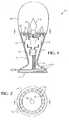
- Fig. 3is a diagrammatic elevational sectional view of an Edison-style light bulb according to another embodiment of our invention.
- Fig. 4is a sectional view along line 4-4 of Fig. 3;
- Fig. 5is a diagrammatic elevational sectional view of an Edison-style light bulb according to another embodiment of our invention.
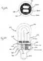
- Figs. 6A and 6Bare a cross-sectional and top view, respectively, of another bulb according to an embodiment of our invention.
- Fig. 7is a perspective view of another bulb according to another embodiment of our invention.
- Fig. 8is a side view of the bulb shown in Fig. 7.
- Fig. 9is a partially exploded view of the bulb shown in Figs. 8 and 9.
- a lamp 10includes a base 12 having a flat bottom 14, which may rest on a horizontal surface, such as a table top or a desk, and a translucent shade 16, which extends up from the base and which permits light generated therein to be emitted out from the lamp.
- the base 12includes a bulb support 18 near its upper end.
- the bulb support 18serves as a mounting for a plurality of light emitting diodes (LEDs) 20 as well as a socket 22 for an illumination bulb 24, which may be, for example, a conventional, screw-in incandescent bulb.
- LEDs 20 and the illumination bulb 24are positioned so that light generated from these devices can be emitted through the shade 16.
- the bulb support 18as shown in Fig. 2, has an outer portion 18a in the form of a ring; and the LEDs 20 are distributed around this outer portion.
- the bulb support 18also includes a center portion 18b which supports the illumination bulb socket 22.
- a first electrical circuit 26is provided in the base 12 and is connected to supply electrical power to each of the LEDs 20.
- a second electrical circuit 28, also provided in the base 12,is connected to supply electrical power to the illumination bulb socket 22.
- a switch circuit 30is also provided in the base 12 and is connected to supply electrical power to the first and second electrical circuits 26 and 28.
- the switch circuit 30is connected to a power line 32, which may receive electrical power from a battery (not shown) contained within the lamp base 12, or from an outside source such as a household electrical output.
- the switch circuit 30includes a program control unit 34, which is configured to switch electrical power to the first and second electrical circuits 26 and 28 as desired, i.e., either to both simultaneously or to each alternately, depending on the type of light to be produced by the lamp 10.
- the program control unitincludes control switch actuators 34, which are located on the base 12 for manual adjustment of the output intensity or brightness of the LEDs 20 and of the illumination bulb 24.
- the program control unit 34may also incorporate an internal program and associated circuits which provide adjustment of the LEDs 20 and the illumination bulb 24 in a predetermined manner. This can provide selectable light shows among which a user may choose.
- sensorsmay be provided to sense other conditions in the area of the lamp 10, e.g., temperature, scent, sound, motion, etc., and to adjust the program in the program control unit 34 so as to coordinate the light outputs from the lamp 10 with such sensed conditions.
- an Edison-style light bulb 40includes a threaded, Edison-style base 42 for use with conventional light bulb sockets. (Of course, the bulb may be configured to mount in other conventional sockets for mounting light bulbs, such as fluorescent and halogen.)
- a translucent housing 46extends up from base 42. The translucent housing 46 allows light generated therein to be emitted from the bulb.
- a lighting support 48is positioned within housing 46, and serves as a mounting for a plurality of LEDs 50 and an illumination source mounting socket 52. Socket 52 mounts, and provides power to, an incandescent illumination source 54. Light generated by the LEDs 50 and illumination source 54 is emitted through housing 46. Housing 46 may be releasably secured to base 42, to allow for replacement of illumination source 54.
- the light source support 48has an outer portion 48a in the form of a ring.
- the LEDs 50are distributed around this outer portion.
- the light source support 48also includes a center portion 48b which supports socket 52, or the illumination source 54, when the illumination source 54 is fixedly mounted on support 48 without a socket.
- a socketis preferably used in order to allow for replacement of burned out illumination sources, since the LEDs 56 are expected to outlast any conventional illumination source.
- a first electrical circuit 56is connected to supply electrical power to each of the LEDs 50.
- a second electrical circuit 58is connected to supply electrical power to illumination source 54.
- a switch circuit 60which is connected to supply electrical power to the first and second electrical circuits 56 and 58.
- the switch circuit 60is connected to power supply line 62, which receives electrical power from an Edison-style light bulb socket when mounted thereon.
- the switch circuit 60includes a program control unit 64, which is configured to switch electrical power to the first and second electrical circuits 56 and 58 as desired, depending on the type of light to be produced.
- the program control unit 64includes control switch actuators 64a, which are located on the outside of housing 46.
- the control switch actuators 64aprovide for switching between different modes of light presentation, i.e., activating either one of first and second electrical circuits 56 and 58, or activating both simultaneously.
- the program control unit 64also includes switch actuators 64b, also located on the outside housing 46, for manual adjustment of, for example, the output intensity or brightness of the LEDs 50 and illumination source 54, pre-programmed light shows using the LEDs 50, the color of the light provided by the LEDs 50, etc.
- the control switch actuators 64bmay operate by controlling internal programs and associated circuits of program control unit 64.
- any one of a number of control mechanismsmay be used in keeping with the present invention including microprocessors, mechanical activity devices, software driven control, and the like.
- the depicted LEDs 50may also be individual groups of light emitting diodes.
- a single LED group 50may include three individual light emitting diodes specific to colors red, green, and blue, respectively.
- the program control unit 64may individually set the relative intensity of each of the light emitting diodes of each group so as to control the color emitted from those groups, i.e., the color emitted from a depicted LED group 50 may be varied based on the combination of colors from the individual light emitting diodes of the group.
- a usermay perceive the combined color by way of positioning the individual diodes of an LED group 50 so closely together as to produce an overall color effect, or alternatively, a translucent shade (e.g., a diffuser) 52 may be provided to cover each LED 50, thus providing for a single perceived color to be emitted from each shade 52 as if it were a single pixel.
- a translucent shadee.g., a diffuser
- the program control unit 64further includes a sensor input 66 for receiving signals from a sensor 66a.
- Sensor 66amay be provided on the light bulb 40 or at a remote location. When positioned at a remote location, signals from sensor 66a may be transmitted to the sensor input 66 by way of a direct connection or a wireless connection (i.e., radio signal, infrared signal, etc.).
- Sensor 66amay sense such stimuli as temperature, sound, motion, etc.
- the program control unit 64may adjust a program for operation of LEDs 50 and illumination source 54 based on the sensed conditions.
- control signalsmay also be provided by direct connection or a wireless connection by a user, rather than a sensor.
- direct connectiona user may simply vary the application of the power source by toggling a power switch which controls the power supply to the device with which bulb 40 is mated.
- the sensor input 66may sense the power supply and change the control of the device based on the timing of the activation and deactivation of the power supply.
- a remote controlmay be provided so that a user may send control signals (e.g., radio signals, infrared signals, etc.) to the sensor input 66.
- control signalse.g., radio signals, infrared signals, etc.
- Fig. 5shows an Edison-style light bulb 70 according to yet another embodiment of our invention.
- a fluorescent illumination source 55is mounted on a socket 53.
- the illuminationmay be provided in a conventional light bulb socket, which allows for replacement of the bulb, or alternatively may be a lighting device permanently affixed to a device according to our invention.
- the remainder of the features of light bulb 70are similar to the like-numbered features discussed above with respect to light bulb 40, shown in Fig. 3.
- Figs. 6A and 6Bshow another embodiment of our invention embodied in bulb 100.
- Bulb 100is similar to previous embodiments in that it includes a base 140 having a screw-in connector 150 adapted to mate with a conventional incandescent light bulb socket in a lamp or the like.
- connector 150may be of any one of a number of configurations that mate with other conventional light sockets (e.g., fluorescent, halogen, etc.).
- Bulb 100also includes a translucent housing 130.
- Housing 130encloses bulbs 110. While other light emitting devices may be provided to provide the bright, white light associated with conventional light bulbs, it is preferred that compact fluorescent bulbs be used. (Of course, bulbs 110 may be replaceable light bulbs, or more permanently affixed light emitting devices.) In this embodiment, we will discuss a plurality of compact fluorescent bulbs which are provided to increase the power of the bulb 100 and the overall surface area within housing 130 emitting white light (or the like).
- compact fluorescent bulbs 110are each formed in an upside down, substantially U-shaped configuration.
- a compact fluorescent bulb 110may have a first electrode at one end from which it extends up in a direction away from base 140, until it bends back on itself near the top of housing 130, so as to extend back toward base 140 to a second electrode at the other end.
- Figs. 6A and 6Bshow two such bulbs 110.
- compact fluorescent bulbs 110can be formed of a single bulb that has a plurality of separate lengths, each of which extends up from the base 140 and then bends back on itself to extend back to base 140, with the lengths being interconnected so as to have only two electrodes, each at opposite ends of the total length. More specifically, while Figs. 6A and 6B appear to show two separate U-shaped bulbs, the term plurality of compact fluorescent bulbs used within this specification can refer to a single compact fluorescent bulb that is bent multiple times to have distinct lengths, as shown in Figs. 6A and 6B.
- the total length of the multiple compact fluorescent bulbs 110is in the range of about 2 to about 21 inches, whether the compact fluorescent bulbs are actually distinct bulbs, or a single bulb having a plurality of distinct lengths. Preferably, this could include about 1 inch lengths, with one bend, to about 3.5 inch lengths, with 1 to 3 bends. This provides a high surface area of light emission to provide ample light to illuminate a room or the like. Also, it should be noted that any number of shapes and configurations may be used to form compact fluorescent bulbs 110 (or other bulbs), other than the U-shaped configuration shown in the figures. For instance, spiral or helical shapes may be used.
- Bulb 100also includes a plurality of LEDs 120. Similar to embodiments discussed above, LEDs 120 are arranged on an LED board 122 so as to encircle the compact fluorescent bulbs 110. In addition, LEDs 120 include a number of different color LEDs. More specifically, as shown in this embodiment, the LEDs of different colors are arranged such that adjacent individual LEDs 120a and LEDs 120b are LEDs of different colors. With such a configuration, the different colored LEDs may be evenly spaced around the inside of housing 130 to provide a suitable light display when perceived from any side of bulb 100.
- the LEDsmay also be configured differently such that a grouping of different colored LEDs may be positioned close to each other (and optionally, covered by a light diffuser so that the group acts as a single pixel) to give increased control over the perception by a user of the colors to be emitted from housing 130.
- LEDs. 120may be controlled to provide a more fluid, continuous change between different emitted colors (e.g., color wash). In the embodiment shown in Figs.
- the separation of differently colored LEDs 120a and 120bprovides a more distinct and delineated change of colors, as perceived by user, in comparison with an embodiment in which a group of differently colored LEDs 120 are positioned close to each other so as to be perceived by user as a single pixel.
- the arrangementmay include close groupings of LEDs, with individual LEDs or the grouping still being separately discernable.
- LEDs 120, compact fluorescent bulbs 110 and LED board 122are mounted on base 140, directly or indirectly.
- Base 140includes a control circuit board 160 which includes LED power supply 164 and compact fluorescent bulb power supply 162. By providing power (and control) for these features on one board, a more compact bulb 100 is achieved.
- Board 160may include conventional switches and potentiometers for controlling the functions of the LEDs 120 and fluorescent bulbs 110, as would be understood by one of ordinary skill in the art. Alternatively, separate boards may be provided for LEDs 120 and compact fluorescent bulbs 110. Electrical power is supplied to board 160 through its electrical connection (not shown) to connector 150, which receives power when mated with a conventional light socket.
- Control board 160may also include a processor 166 that may use various combinations of software and hardware to control the various lighting functions.
- the controlmay involve control of the color to be emitted by LEDs 120, individually or as a group, when perceived by a user from outside of housing 130 (this may involve the use of a diffuser or the like).
- the control mechanismsmay control the brightness of the LEDs 120.
- the controlmay involve the running of predetermined lighting presentations (e.g., light shows) that vary the light color, brightness, activation, etc., over the course of the presentation to provide an entertaining lighting show.
- the control mechanismsmay also control the compact fluorescent bulbs 110, including their brightness or activation.
- the compact fluorescent bulbs 110are activated on their own, without LEDs 120, to provide normal white light for illuminating a room or other area.
- the LEDsmay be used separately as night lights or to provide ambience using color features or color shows that are pleasing to a user.
- the light showsmay be stored in a memory 168, which may also be included on the control board 160 (or integrated with processor 166).
- the memory 168may include software programs for controlling the circuit board 160 and/or processor 166 to operate the predetermined presentations.
- a user interface 170is provided on base 140 so as to provide a user with control of the control board 160 and/or processor 166.
- the user interfacemay allow the user to select the colors, brightness, activation, etc. of the LEDs 120 and compact fluorescent bulbs 110.
- the user interface 170is a button which a user can toggle to switch between different settings.
- user interface 170may be more elaborate (and be provided at base 140, or remote locations) so as to allow a user more sophisticated control of the operation of the bulb 100. This could include the ability to design programs including color changes, changes in brightness of various components, timed activations and/or deactivations, etc., and combinations thereof.
- FIGs 7-9show a modification of the bulb shown in Figs. 6A and 6B.
- three compact fluorescent bulbs 110which may include three distinct fluorescent bulbs or three distinct lengths of light emission of a single fluorescent bulb.
- the separate compact fluorescent bulbs 110are provided so as to extend from the base 140 vertically up through the housing 130 to a position near the top thereof.
- LEDs 120are not arranged circularly around the compact fluorescent bulbs 110 near the base 140, but are arranged in vertical groupings, each grouping extending between separate compact fluorescent bulbs 110.
- each grouping of LEDs 120 extending between adjacent compact fluorescent bulbs 110may be secured to a separate LED board 122. This provides a slightly different lighting effect that may distribute colored light more effectively.
- our inventionprovides a bulb similar in size, shape and compatibility to conventional light bulbs, but with enhanced features and control, including colors, color changing and light shows.
- our inventionstill mates with conventional light sockets, and is generally shaped similarly to that of a conventional incandescent bulb (at least in one embodiment), it may be used in existing light fixtures and accommodate conventional light shades.
- housing 130is preferably shaped/sized so as to be able to receive the connection means provided on conventional light shades to secure the same to typical light bulbs.
- the diameter of housing 130 at position 132is preferably in the range of about 1.75 to about 3.25 inches, and the diameter of housing 130 at position 134 is preferably about 1 to about 3 inches.
- the of the bulbsubstantially complies with conventional bulb sizes A-19 (with position 132 measuring about 2.375 inches) and A-21 (with position 132 measuring about 2.625 inches).
- bulb 100preferably emits white light from compact fluorescent bulbs, or other light emission devices in a range of about 160 to about 4200 lumens; and more preferably in the range of about 240 to about 2625 lumens; and most preferably in the range of about 320 to about 2100 lumens.
- a bulb according to our inventionpreferably draws power in the range of about 5 to about 200 watts; and more preferably in a range of about 15 to about 125 watts; and most preferably in a range of about 25 to about 100 watts. Consequently, our invention is designed for use in many settings where conventional bulbs would typically be used.
- illumination sourcessuch as a halogen bulb or high intensity discharge bulb, may be used to provide illumination light, as would be readily understood by one of ordinary skill in the art.
- the first such embodimentis an electrical lamp comprising an illumination socket mounting an illumination bulb, chosen from the group consisting essentially of incandescent bulbs, fluorescent bulbs and halogen bulbs, which bulb emits illumination light when supplied with electrical power; a plurality of light emitting diodes which emit light of different colours when supplied with electrical power; a base in which the illumination socket and the light emitting diodes are positioned in proximity to each other; a first electrical circuit connected to supply electrical power to an illumination bulb mounted in the illumination socket for causing the illumination bulb to emit illuminating light; a second electrical circuit connected to supply electrical power to the light emitting diodes for causing the light emitting diodes to emit light of different colours; and switching means for selectively switching the application of electrical power between the first electrical circuit and the second electrical circuit.
- an illumination bulbchosen from the group consisting essentially of incandescent bulbs, fluorescent bulbs and halogen bulbs, which bulb emits illumination light when supplied with electrical power
- a plurality of light emitting diodeswhich emit light of different colours when supplied with electrical
- the first electrical circuitmay include a dimmer to adjust the intensity of the illumination light.
- the second electrical circuitmay include a dimmer configured for selective adjustment of the intensities of the light of different colours.
- Theremay be included a programmable circuit connected to the second electrical circuit and configured to adjust the intensities of the light of different colours according to a predetermined program.
- the second such embodimentis a light bulb comprising an illumination source, chosen from the group consisting essentially of incandescent, fluorescent and halogen light emitting devices, which source emits illumination light; a plurality of light emitting diodes which emit light of different colours; a base on which the illumination source and the plurality of light emitting diodes are mounted in proximity to each other, the base being configured to mount in a light bulb socket; a first electrical circuit connected to supply electrical power to the illumination source; a second electrical circuit connected to supply electrical power to the light emitting diodes; and a switch for selectively switching the application of electrical power between the first electrical circuit and the second electrical circuit.
- the first electrical circuitmay include a dimmer to adjust the intensity of the illumination light.
- the second electrical circuitmay include a dimmer configured for selective adjustment of the intensities of the light of different colours.
- the light bulbmay further include a programmable circuit connected to the second electrical circuit and configured to adjust the intensities of the light of different colours according to a predetermined program.
- the light bulbmay further include a sensor for sensing at least one of temperature, scent, motion, and sound, and a programmable circuit connected to the second electrical circuit, wherein the programmable circuit would adjust at least one of the intensities and colours of the light of different colours in response to a signal from the sensor.
- the illumination sourcemay be releasably mounted in the light bulb.
- the third such embodimentis a light bulb comprising a base configured to mate with a light bulb socket; at least one compact fluorescent bulb mounted on the base; a plurality of light emitting diodes mounted on the base, which emit light of different colours; a control circuit which supplies power from the light socket, when the base is mounted therein, to the at least one fluorescent bulb and the plurality of light emitting diodes; and a translucent housing mounted on the base and containing the at least one fluorescent bulb and the plurality of light emitting diodes.
- the bulbmay comprise a plurality of compact fluorescent bulbs.
- the at least one fluorescent bulbmay be about 2 to about 21 inches in length, the fluorescent bulb being folded back on itself a plurality of times so as to form a plurality of lengths extending up from the base within the housing.
- the bulbcomprises a plurality of compact fluorescent bulbs there may be provided a plurality of light emitting diodes positioned around the fluorescent bulbs, in a circumferential direction. In this case adjacent light emitting diodes, in a circumferential direction, may be different colour light emitting diodes. Alternatively there may be a plurality of light emitting diodes positioned around the at least one of fluorescent bulb. In this case adjacent light emitting diodes, in a circumferential direction, may also be different colour light emitting diodes.
- the plurality of light emitting diodesmay be positioned on the base so as to surround the at least one fluorescent bulb. In this case too adjacent light emitting diodes, in a circumferential direction, may be different colour light emitting diodes.
- the at least one fluorescent bulb and the plurality of light emitting diodesmay be powered from a common circuit board.
- the at least one fluorescent bulbmay emit light within the range of about 160 to about 4200 lumens.
- at least one fluorescent bulbmay emit light within the range of about 240 to about 2625 lumens, preferably within the range of about 320 to about 2100 lumens.
- the bulb of this embodimentmay further comprise a processor for controlling the control circuit to control the plurality of light emitting diodes to produce a at least one predetermined presentation of light emission which varies, during the presentation, at least one of the colour and intensity of light emitted from the housing by the plurality of light emitting diodes.
- the bulbmay further comprise a memory storing one or more programs defining the at least one predetermined presentation.
- the bulbmay further comprise a user interface that allows a user to select from the at least one predetermined presentation.
- the bulbmay further comprise a user interface that allows a user to perform at least one of i) activating one or more of a plurality of predetermined presentations; and ii) selecting one or more colours of light to be emitted from the housing by the plurality of light emitting diodes.
- the processormay be controlled remotely by a user so as to perform at least one of i) activating one or more of a plurality of predetermined presentations; and ii) selecting one or more colours of light to be emitted from the housing by the plurality of light emitting diodes.
- the bulbfurther comprises a sensor for sensing power activation so as to enable the user to remotely control the processor by toggling a power switch that controls the power through the light socket on which the bulb is mounted.
- the bulbmay further comprise a sensor that enables the processor to be remotely controlled by one of an infrared signal and a radio signal.
- a fourth such embodimentis a light bulb comprising a base configured to mate with a light bulb socket; a light emitting device mounted on and receiving power from the base, the light emitting device being selected from the group consisting essentially of halogen, incandescent, fluorescent, and low vapour mercury light emitting devices; a plurality of light emitting diodes mounted on and receiving power from the base, the plurality of light emitting diodes emitting light of different colours; a programmable processor that controls the activation, colour and intensity of the light emitted from the plurality of the light emitting diodes; and a translucent housing mounted on the base and containing the light emitting device and the plurality of light emitting diodes.
- the light-emitting devicemay emit light in the range of about320 to about 2100, lumens.
- Adjacent light emitting diodes mounted on the base, in a circumferential direction,may be different colour light emitting diodes.
- the bulbmay, further comprise a memory storing programs for instructing the processor to perform a plurality of predetermined presentations of light emission each of which varies at least one of the colour and intensity of light emitted from the housing by the plurality of light emitting diodes.
- the programsmay be activated remotely by a user.
- a fifth such embodimentis a light bulb comprising a base configured to mate with a light bulb socket; a light emitting device mounted on and receiving power from the base, the light emitting device being selected from the group consisting essentially of halogen, incandescent, fluorescent, and low vapour mercury light emitting devices; a plurality of light emitting diodes mounted on and receiving power from the base, the plurality of light emitting diodes emitting light of different colours; a user interface that controls the activation, colour and intensity of the light emitted from the plurality of the light emitting diodes; and a translucent housing mounted on the base and containing the light emitting device and the plurality of light emitting diodes.
- the user interfacemay control a plurality of predetermined presentations of light emission stored in the bulb, each of which varies at least one of the colour and intensity of light emitted from the housing by the plurality of light emitting diodes.
- This inventionprovides lighting for both illumination purposes and for the creation of desired ambient conditions in a single device, which may be adjusted manually to change the lighting and which may be programmed to automatically change such lighting.
Landscapes
- Engineering & Computer Science (AREA)
- General Engineering & Computer Science (AREA)
- Physics & Mathematics (AREA)
- Microelectronics & Electronic Packaging (AREA)
- Optics & Photonics (AREA)
- Non-Portable Lighting Devices Or Systems Thereof (AREA)
- Circuit Arrangement For Electric Light Sources In General (AREA)
- Arrangement Of Elements, Cooling, Sealing, Or The Like Of Lighting Devices (AREA)
- Polymerisation Methods In General (AREA)
- Endoscopes (AREA)
Abstract
Description
- Our invention relates to novel lighting devices which provide light for illumination as well as ambient light.
- Electric lamps, and the light bulbs used therein, which provide illumination are well known and are widely used. These lamps and bulbs fall into two general categories, namely, incandescent and fluorescent. More recent developments in lighting have led to advancement in light emitting diodes (LEDs). An LED is a semiconductor device that emits visible light when an electrical current passes through it. The light from an LED is basically monochromatic and the color of the light is determined by the particular material used in the semiconductor (although current applied to the LED can be used to vary the perceived color). LEDs have the advantage of low power requirements, high efficiency and long life. The outputs of several different color LEDs can be mixed so as to produce additional colors, including white light, and different brightness. LEDs can also be used to provide background lighting to achieve desired ambient effects. However, they have limited brightness and therefore they are generally not suitable for illumination purposes. Instead, LEDs have been generally used for such applications as indicator lights, panel backlighting and fiber optic data transmission.
U.S. Patent No. 6,149,283 discloses an LED lamp/bulb having a multicolor adjustor. This device comprises a base in which several LEDs capable of producing different colored light are mounted. Adjustable switches are provided for the different color LEDs so that the colors can be mixed in any desired ratio to produce desired lighting effects such as varying colors, including white light, and varying brightness. This patent acknowledges that the lumen output of LEDs is not as high as an incandescent source of the identical wattage.U.S. Patent No. 5,924,784 discloses providing ambient light (simulating a candle flame) from both a free-standing lamp and an Edison-style light bulb (i.e., a screw-in bulb that mates with a conventional light bulb socket) using LEDs. The flame simulation is provided through both color combinations emitted and flicker effects. The patent states that it is directed to bulbs and lamps used for achieving soothing effects in memorials and the like.U.S. Patents No. 6,016,038 ,No. 6,150,774 ,No. 6,166,496 ,No. 6,211,626 ,No. 6,292,901 andNo. 6,340,868 disclose various techniques and electrical circuits for controlling the light output of several LEDs according to predetermined programs.- This invention makes possible the provision of desired ambient or background light together with illumination light in a single lamp fixture or light bulb.
- According to one embodiment of our invention, there is provided a novel electrical lamp which includes an illumination socket for mounting an illumination bulb which emits illumination light, a plurality of light emitting diodes which emit light of different colors, a base in which the illumination socket and the light emitting diodes are positioned in proximity to each other, a first electrical circuit connected to supply electrical power to the illumination socket, a second electrical circuit connected to supply electrical power to the light emitting diodes, and switching means connected to selectively switch the application of electrical power between the first electrical circuit and the second electrical circuit. The illumination socket is a socket for mounting an illumination bulb selected from the group consisting essentially of incandescent bulbs, fluorescent bulbs and halogen bulbs.
- In another embodiment, our invention is directed to a light bulb. The bulb includes an illumination source which emits illumination light, a plurality of light emitting diodes which emit light of different colors, a base on which the illumination source and plurality of light emitting diodes are mounted in proximity to each other, a first electrical circuit connected to supply electrical power to the socket, a second electrical circuit connected to supply electrical power to the light emitting diodes, and a switch connected to selectively switch the application of electrical power between the first electrical circuit and second electrical circuit. Also, the illumination source is selected from the group consisting essentially of incandescent bulbs, fluorescent bulbs and halogen bulbs. (When we talk about such conventional "bulbs" used in connection with the lamps and bulbs according to our invention, the conventional "bulbs" may include replaceable screw-in bulbs and the like, as well as more permanent light emitting devices mounted in bulbs or lamps of our invention.)
- In another embodiment, our invention is directed to a light bulb having a base configured to mate with a light bulb socket. At least one compact fluorescent bulb is mounted on the base. Also, a plurality of light emitting diodes are mounted on the base, which LEDs emit light of different colors. A control circuit supplies power from the light socket, when the base is mounted therein, to the at least one fluorescent bulb and the plurality of light emitting diodes. A translucent housing is mounted on the base and contains the at least one fluorescent bulb and the plurality of light emitting diodes.
- In yet another embodiment, our invention is directed to a light bulb having a base configured to mate with a light bulb socket. A light emitting device is mounted on and receives power from the base. The light emitting device is selected from the group consisting essentially of halogen, incandescent, fluorescent, and low vapor mercury light emitting devices. A plurality of light emitting diodes are also mounted on and receive power from the base. The plurality of light emitting diodes emit light of different colors. A programmable processor controls the activation, color and intensity of the light emitted from the plurality of the light emitting diodes. Again, a translucent housing is mounted on the base and contains the light emitting device and the plurality of light emitting diodes.
- In another embodiment, our invention is directed to a light bulb having a base configured to mate with a light bulb socket. A light emitting device is mounted on and receives power from the base. The light emitting device is selected from the group consisting essentially of halogen, incandescent, fluorescent, and low vapor mercury light emitting devices. A plurality of light emitting diodes are mounted on and receive power from the base. The plurality of light emitting diodes emit light of different colors. A user interface controls the activation, color and intensity of the light emitted from the plurality of the light emitting diodes. Further, a translucent housing is mounted on the base and contains the light emitting device and the plurality of light emitting diodes.
- Fig. 1 is a diagrammatic elevational sectional view of a lamp according to one embodiment of our invention;
- Fig. 2 is a sectional view along line 2-2 of Fig. 1;
- Fig. 3 is a diagrammatic elevational sectional view of an Edison-style light bulb according to another embodiment of our invention;
- Fig. 4 is a sectional view along line 4-4 of Fig. 3; and
- Fig. 5 is a diagrammatic elevational sectional view of an Edison-style light bulb according to another embodiment of our invention.
- Figs. 6A and 6B are a cross-sectional and top view, respectively, of another bulb according to an embodiment of our invention.
- Fig. 7 is a perspective view of another bulb according to another embodiment of our invention.
- Fig. 8 is a side view of the bulb shown in Fig. 7.
- Fig. 9 is a partially exploded view of the bulb shown in Figs. 8 and 9.
- As shown in Fig. 1, a
lamp 10 according to one embodiment of our invention includes abase 12 having aflat bottom 14, which may rest on a horizontal surface, such as a table top or a desk, and atranslucent shade 16, which extends up from the base and which permits light generated therein to be emitted out from the lamp. Thebase 12 includes abulb support 18 near its upper end. Thebulb support 18 serves as a mounting for a plurality of light emitting diodes (LEDs) 20 as well as asocket 22 for anillumination bulb 24, which may be, for example, a conventional, screw-in incandescent bulb. As can be seen, theLEDs 20 and theillumination bulb 24 are positioned so that light generated from these devices can be emitted through theshade 16. - The
bulb support 18, as shown in Fig. 2, has an outer portion 18a in the form of a ring; and theLEDs 20 are distributed around this outer portion. Thebulb support 18 also includes a center portion 18b which supports theillumination bulb socket 22. - A first
electrical circuit 26 is provided in thebase 12 and is connected to supply electrical power to each of theLEDs 20. A secondelectrical circuit 28, also provided in thebase 12, is connected to supply electrical power to theillumination bulb socket 22. Aswitch circuit 30 is also provided in thebase 12 and is connected to supply electrical power to the first and secondelectrical circuits switch circuit 30 is connected to apower line 32, which may receive electrical power from a battery (not shown) contained within thelamp base 12, or from an outside source such as a household electrical output. - The
switch circuit 30 includes aprogram control unit 34, which is configured to switch electrical power to the first and secondelectrical circuits lamp 10. The program control unit includescontrol switch actuators 34, which are located on thebase 12 for manual adjustment of the output intensity or brightness of theLEDs 20 and of theillumination bulb 24. Theprogram control unit 34 may also incorporate an internal program and associated circuits which provide adjustment of theLEDs 20 and theillumination bulb 24 in a predetermined manner. This can provide selectable light shows among which a user may choose. In addition, sensors (not shown) may be provided to sense other conditions in the area of thelamp 10, e.g., temperature, scent, sound, motion, etc., and to adjust the program in theprogram control unit 34 so as to coordinate the light outputs from thelamp 10 with such sensed conditions. - As shown in Fig. 3, an Edison-
style light bulb 40 according to another embodiment of the invention includes a threaded, Edison-style base 42 for use with conventional light bulb sockets. (Of course, the bulb may be configured to mount in other conventional sockets for mounting light bulbs, such as fluorescent and halogen.) Atranslucent housing 46 extends up frombase 42. Thetranslucent housing 46 allows light generated therein to be emitted from the bulb. - A
lighting support 48 is positioned withinhousing 46, and serves as a mounting for a plurality ofLEDs 50 and an illuminationsource mounting socket 52.Socket 52 mounts, and provides power to, anincandescent illumination source 54. Light generated by theLEDs 50 andillumination source 54 is emitted throughhousing 46.Housing 46 may be releasably secured tobase 42, to allow for replacement ofillumination source 54. - The
light source support 48, as shown in Figure 4, has an outer portion 48a in the form of a ring. TheLEDs 50 are distributed around this outer portion. Thelight source support 48 also includes a center portion 48b which supportssocket 52, or theillumination source 54, when theillumination source 54 is fixedly mounted onsupport 48 without a socket. A socket is preferably used in order to allow for replacement of burned out illumination sources, since theLEDs 56 are expected to outlast any conventional illumination source. - A first
electrical circuit 56 is connected to supply electrical power to each of theLEDs 50. A second electrical circuit 58 is connected to supply electrical power toillumination source 54. Also provided is aswitch circuit 60, which is connected to supply electrical power to the first and secondelectrical circuits 56 and 58. Theswitch circuit 60 is connected topower supply line 62, which receives electrical power from an Edison-style light bulb socket when mounted thereon. Theswitch circuit 60 includes aprogram control unit 64, which is configured to switch electrical power to the first and secondelectrical circuits 56 and 58 as desired, depending on the type of light to be produced. Theprogram control unit 64 includes control switch actuators 64a, which are located on the outside ofhousing 46. The control switch actuators 64a provide for switching between different modes of light presentation, i.e., activating either one of first and secondelectrical circuits 56 and 58, or activating both simultaneously. Theprogram control unit 64 also includes switch actuators 64b, also located on theoutside housing 46, for manual adjustment of, for example, the output intensity or brightness of theLEDs 50 andillumination source 54, pre-programmed light shows using theLEDs 50, the color of the light provided by theLEDs 50, etc. The control switch actuators 64b may operate by controlling internal programs and associated circuits ofprogram control unit 64. In addition, any one of a number of control mechanisms may be used in keeping with the present invention including microprocessors, mechanical activity devices, software driven control, and the like. - Also, we have referred to the depicted
LEDs 50 as separate light emitting diodes; however, the depictedLEDs 50 may also be individual groups of light emitting diodes. For instance, asingle LED group 50 may include three individual light emitting diodes specific to colors red, green, and blue, respectively. With such a configuration, theprogram control unit 64 may individually set the relative intensity of each of the light emitting diodes of each group so as to control the color emitted from those groups, i.e., the color emitted from a depictedLED group 50 may be varied based on the combination of colors from the individual light emitting diodes of the group. A user may perceive the combined color by way of positioning the individual diodes of anLED group 50 so closely together as to produce an overall color effect, or alternatively, a translucent shade (e.g., a diffuser) 52 may be provided to cover eachLED 50, thus providing for a single perceived color to be emitted from eachshade 52 as if it were a single pixel. - The
program control unit 64 further includes asensor input 66 for receiving signals from a sensor 66a. Sensor 66a may be provided on thelight bulb 40 or at a remote location. When positioned at a remote location, signals from sensor 66a may be transmitted to thesensor input 66 by way of a direct connection or a wireless connection (i.e., radio signal, infrared signal, etc.). - Sensor 66a may sense such stimuli as temperature, sound, motion, etc. The
program control unit 64 may adjust a program for operation ofLEDs 50 andillumination source 54 based on the sensed conditions. - In addition, control signals may also be provided by direct connection or a wireless connection by a user, rather than a sensor. For instance, as regards direct connection, a user may simply vary the application of the power source by toggling a power switch which controls the power supply to the device with which
bulb 40 is mated. In this case, thesensor input 66 may sense the power supply and change the control of the device based on the timing of the activation and deactivation of the power supply. Alternatively, a remote control may be provided so that a user may send control signals (e.g., radio signals, infrared signals, etc.) to thesensor input 66. These control options may be provided in addition to or in lieu of switches 64a and 64b. - Fig. 5 shows an Edison-
style light bulb 70 according to yet another embodiment of our invention. In this embodiment, afluorescent illumination source 55 is mounted on asocket 53. Of course, the illumination may be provided in a conventional light bulb socket, which allows for replacement of the bulb, or alternatively may be a lighting device permanently affixed to a device according to our invention. The remainder of the features oflight bulb 70 are similar to the like-numbered features discussed above with respect tolight bulb 40, shown in Fig. 3. - Figs. 6A and 6B show another embodiment of our invention embodied in bulb 100. Bulb 100 is similar to previous embodiments in that it includes a base 140 having a screw-in connector 150 adapted to mate with a conventional incandescent light bulb socket in a lamp or the like. Of course, connector 150 may be of any one of a number of configurations that mate with other conventional light sockets (e.g., fluorescent, halogen, etc.).
- Bulb 100 also includes a
translucent housing 130.Housing 130 enclosesbulbs 110. While other light emitting devices may be provided to provide the bright, white light associated with conventional light bulbs, it is preferred that compact fluorescent bulbs be used. (Of course,bulbs 110 may be replaceable light bulbs, or more permanently affixed light emitting devices.) In this embodiment, we will discuss a plurality of compact fluorescent bulbs which are provided to increase the power of the bulb 100 and the overall surface area withinhousing 130 emitting white light (or the like). - As is shown in Fig. 6A,
compact fluorescent bulbs 110 are each formed in an upside down, substantially U-shaped configuration. (Of course, other arrangements are possible while keeping with the scope of our invention). In particular, acompact fluorescent bulb 110 may have a first electrode at one end from which it extends up in a direction away frombase 140, until it bends back on itself near the top ofhousing 130, so as to extend back towardbase 140 to a second electrode at the other end. Figs. 6A and 6B show twosuch bulbs 110. - Alternatively,
compact fluorescent bulbs 110 can be formed of a single bulb that has a plurality of separate lengths, each of which extends up from thebase 140 and then bends back on itself to extend back tobase 140, with the lengths being interconnected so as to have only two electrodes, each at opposite ends of the total length. More specifically, while Figs. 6A and 6B appear to show two separate U-shaped bulbs, the term plurality of compact fluorescent bulbs used within this specification can refer to a single compact fluorescent bulb that is bent multiple times to have distinct lengths, as shown in Figs. 6A and 6B. - In a most preferred embodiment, the total length of the multiple
compact fluorescent bulbs 110 is in the range of about 2 to about 21 inches, whether the compact fluorescent bulbs are actually distinct bulbs, or a single bulb having a plurality of distinct lengths. Preferably, this could include about 1 inch lengths, with one bend, to about 3.5 inch lengths, with 1 to 3 bends. This provides a high surface area of light emission to provide ample light to illuminate a room or the like. Also, it should be noted that any number of shapes and configurations may be used to form compact fluorescent bulbs 110 (or other bulbs), other than the U-shaped configuration shown in the figures. For instance, spiral or helical shapes may be used. - Bulb 100 also includes a plurality of
LEDs 120. Similar to embodiments discussed above,LEDs 120 are arranged on anLED board 122 so as to encircle thecompact fluorescent bulbs 110. In addition,LEDs 120 include a number of different color LEDs. More specifically, as shown in this embodiment, the LEDs of different colors are arranged such that adjacent individual LEDs 120a and LEDs 120b are LEDs of different colors. With such a configuration, the different colored LEDs may be evenly spaced around the inside ofhousing 130 to provide a suitable light display when perceived from any side of bulb 100. As discussed above with respect to other embodiments, the LEDs may also be configured differently such that a grouping of different colored LEDs may be positioned close to each other (and optionally, covered by a light diffuser so that the group acts as a single pixel) to give increased control over the perception by a user of the colors to be emitted fromhousing 130. In such embodiments, LEDs. 120 may be controlled to provide a more fluid, continuous change between different emitted colors (e.g., color wash). In the embodiment shown in Figs. 6A and 6B, the separation of differently colored LEDs 120a and 120b provides a more distinct and delineated change of colors, as perceived by user, in comparison with an embodiment in which a group of differently coloredLEDs 120 are positioned close to each other so as to be perceived by user as a single pixel. Alternatively, the arrangement may include close groupings of LEDs, with individual LEDs or the grouping still being separately discernable. LEDs 120,compact fluorescent bulbs 110 andLED board 122 are mounted onbase 140, directly or indirectly.Base 140 includes acontrol circuit board 160 which includesLED power supply 164 and compact fluorescentbulb power supply 162. By providing power (and control) for these features on one board, a more compact bulb 100 is achieved.Board 160 may include conventional switches and potentiometers for controlling the functions of theLEDs 120 andfluorescent bulbs 110, as would be understood by one of ordinary skill in the art. Alternatively, separate boards may be provided forLEDs 120 andcompact fluorescent bulbs 110. Electrical power is supplied to board 160 through its electrical connection (not shown) to connector 150, which receives power when mated with a conventional light socket.Control board 160 may also include a processor 166 that may use various combinations of software and hardware to control the various lighting functions. With respect toLEDs 120, the control may involve control of the color to be emitted byLEDs 120, individually or as a group, when perceived by a user from outside of housing 130 (this may involve the use of a diffuser or the like). In addition, the control mechanisms may control the brightness of theLEDs 120. Further, the control may involve the running of predetermined lighting presentations (e.g., light shows) that vary the light color, brightness, activation, etc., over the course of the presentation to provide an entertaining lighting show. The control mechanisms may also control thecompact fluorescent bulbs 110, including their brightness or activation. In preferred embodiments, thecompact fluorescent bulbs 110 are activated on their own, withoutLEDs 120, to provide normal white light for illuminating a room or other area. The LEDs may be used separately as night lights or to provide ambience using color features or color shows that are pleasing to a user.- The light shows may be stored in a
memory 168, which may also be included on the control board 160 (or integrated with processor 166). Thememory 168 may include software programs for controlling thecircuit board 160 and/or processor 166 to operate the predetermined presentations. - A
user interface 170 is provided onbase 140 so as to provide a user with control of thecontrol board 160 and/or processor 166. The user interface may allow the user to select the colors, brightness, activation, etc. of theLEDs 120 andcompact fluorescent bulbs 110. In the depicted embodiment, theuser interface 170 is a button which a user can toggle to switch between different settings. In other embodiments,user interface 170 may be more elaborate (and be provided atbase 140, or remote locations) so as to allow a user more sophisticated control of the operation of the bulb 100. This could include the ability to design programs including color changes, changes in brightness of various components, timed activations and/or deactivations, etc., and combinations thereof. - Figures 7-9 show a modification of the bulb shown in Figs. 6A and 6B. In particular, there are provided three compact fluorescent bulbs 110 (which may include three distinct fluorescent bulbs or three distinct lengths of light emission of a single fluorescent bulb). Again, the separate compact
fluorescent bulbs 110 are provided so as to extend from the base 140 vertically up through thehousing 130 to a position near the top thereof. In this embodiment, however,LEDs 120 are not arranged circularly around thecompact fluorescent bulbs 110 near thebase 140, but are arranged in vertical groupings, each grouping extending between separatecompact fluorescent bulbs 110. As shown in Fig. 9, each grouping ofLEDs 120 extending between adjacentcompact fluorescent bulbs 110 may be secured to aseparate LED board 122. This provides a slightly different lighting effect that may distribute colored light more effectively. - With the above-described various embodiments, our invention provides a bulb similar in size, shape and compatibility to conventional light bulbs, but with enhanced features and control, including colors, color changing and light shows. However, because our invention still mates with conventional light sockets, and is generally shaped similarly to that of a conventional incandescent bulb (at least in one embodiment), it may be used in existing light fixtures and accommodate conventional light shades. Specifically,
housing 130 is preferably shaped/sized so as to be able to receive the connection means provided on conventional light shades to secure the same to typical light bulbs. In particular, with respect to Fig. 6A, the diameter ofhousing 130 at position 132 (a wider top portion of housing 130) is preferably in the range of about 1.75 to about 3.25 inches, and the diameter ofhousing 130 atposition 134 is preferably about 1 to about 3 inches. Most preferably the of the bulb substantially complies with conventional bulb sizes A-19 (withposition 132 measuring about 2.375 inches) and A-21 (withposition 132 measuring about 2.625 inches). - In addition, bulb 100 preferably emits white light from compact fluorescent bulbs, or other light emission devices in a range of about 160 to about 4200 lumens; and more preferably in the range of about 240 to about 2625 lumens; and most preferably in the range of about 320 to about 2100 lumens. Also, a bulb according to our invention preferably draws power in the range of about 5 to about 200 watts; and more preferably in a range of about 15 to about 125 watts; and most preferably in a range of about 25 to about 100 watts. Consequently, our invention is designed for use in many settings where conventional bulbs would typically be used.
- It should also be recognized, however, that other suitable illumination sources, such as a halogen bulb or high intensity discharge bulb, may be used to provide illumination light, as would be readily understood by one of ordinary skill in the art.
- The following broadly defined embodiments are contemplated as falling within the ambit of the present invention. The first such embodiment is an electrical lamp comprising an illumination socket mounting an illumination bulb, chosen from the group consisting essentially of incandescent bulbs, fluorescent bulbs and halogen bulbs, which bulb emits illumination light when supplied with electrical power; a plurality of light emitting diodes which emit light of different colours when supplied with electrical power; a base in which the illumination socket and the light emitting diodes are positioned in proximity to each other; a first electrical circuit connected to supply electrical power to an illumination bulb mounted in the illumination socket for causing the illumination bulb to emit illuminating light; a second electrical circuit connected to supply electrical power to the light emitting diodes for causing the light emitting diodes to emit light of different colours; and switching means for selectively switching the application of electrical power between the first electrical circuit and the second electrical circuit. The first electrical circuit may include a dimmer to adjust the intensity of the illumination light. The second electrical circuit may include a dimmer configured for selective adjustment of the intensities of the light of different colours. There may be included a programmable circuit connected to the second electrical circuit and configured to adjust the intensities of the light of different colours according to a predetermined program.
- The second such embodiment is a light bulb comprising an illumination source, chosen from the group consisting essentially of incandescent, fluorescent and halogen light emitting devices, which source emits illumination light; a plurality of light emitting diodes which emit light of different colours; a base on which the illumination source and the plurality of light emitting diodes are mounted in proximity to each other, the base being configured to mount in a light bulb socket; a first electrical circuit connected to supply electrical power to the illumination source; a second electrical circuit connected to supply electrical power to the light emitting diodes; and a switch for selectively switching the application of electrical power between the first electrical circuit and the second electrical circuit. The first electrical circuit may include a dimmer to adjust the intensity of the illumination light. The second electrical circuit may include a dimmer configured for selective adjustment of the intensities of the light of different colours. The light bulb may further include a programmable circuit connected to the second electrical circuit and configured to adjust the intensities of the light of different colours according to a predetermined program. The light bulb may further include a sensor for sensing at least one of temperature, scent, motion, and sound, and a programmable circuit connected to the second electrical circuit, wherein the programmable circuit would adjust at least one of the intensities and colours of the light of different colours in response to a signal from the sensor. The illumination source may be releasably mounted in the light bulb.
- The third such embodiment is a light bulb comprising a base configured to mate with a light bulb socket; at least one compact fluorescent bulb mounted on the base; a plurality of light emitting diodes mounted on the base, which emit light of different colours; a control circuit which supplies power from the light socket, when the base is mounted therein, to the at least one fluorescent bulb and the plurality of light emitting diodes; and a translucent housing mounted on the base and containing the at least one fluorescent bulb and the plurality of light emitting diodes. The bulb may comprise a plurality of compact fluorescent bulbs. The at least one fluorescent bulb may be about 2 to about 21 inches in length, the fluorescent bulb being folded back on itself a plurality of times so as to form a plurality of lengths extending up from the base within the housing. If the bulb comprises a plurality of compact fluorescent bulbs there may be provided a plurality of light emitting diodes positioned around the fluorescent bulbs, in a circumferential direction. In this case adjacent light emitting diodes, in a circumferential direction, may be different colour light emitting diodes. Alternatively there may be a plurality of light emitting diodes positioned around the at least one of fluorescent bulb. In this case adjacent light emitting diodes, in a circumferential direction, may also be different colour light emitting diodes. As another option the plurality of light emitting diodes may be positioned on the base so as to surround the at least one fluorescent bulb. In this case too adjacent light emitting diodes, in a circumferential direction, may be different colour light emitting diodes. In this third broadly defined embodiment the at least one fluorescent bulb and the plurality of light emitting diodes may be powered from a common circuit board. The at least one fluorescent bulb may emit light within the range of about 160 to about 4200 lumens. In this case at least one fluorescent bulb may emit light within the range of about 240 to about 2625 lumens, preferably within the range of about 320 to about 2100 lumens. There may further be provided a user interface connected to the control circuit, wherein the user interface allows for programming of the colour of the light to be emitted from the housing by the plurality of light emitting diodes.
- The bulb of this embodiment may further comprise a processor for controlling the control circuit to control the plurality of light emitting diodes to produce a at least one predetermined presentation of light emission which varies, during the presentation, at least one of the colour and intensity of light emitted from the housing by the plurality of light emitting diodes. In this case the bulb may further comprise a memory storing one or more programs defining the at least one predetermined presentation. In addition the bulb may further comprise a user interface that allows a user to select from the at least one predetermined presentation. If the bulb has a processor and produces a predetermined light presentation as mentioned above, it may further comprise a user interface that allows a user to perform at least one of i) activating one or more of a plurality of predetermined presentations; and ii) selecting one or more colours of light to be emitted from the housing by the plurality of light emitting diodes. Alternatively the processor may be controlled remotely by a user so as to perform at least one of i) activating one or more of a plurality of predetermined presentations; and ii) selecting one or more colours of light to be emitted from the housing by the plurality of light emitting diodes. A further option is where the bulb further comprises a sensor for sensing power activation so as to enable the user to remotely control the processor by toggling a power switch that controls the power through the light socket on which the bulb is mounted. The bulb may further comprise a sensor that enables the processor to be remotely controlled by one of an infrared signal and a radio signal.
- A fourth such embodiment is a light bulb comprising a base configured to mate with a light bulb socket; a light emitting device mounted on and receiving power from the base, the light emitting device being selected from the group consisting essentially of halogen, incandescent, fluorescent, and low vapour mercury light emitting devices; a plurality of light emitting diodes mounted on and receiving power from the base, the plurality of light emitting diodes emitting light of different colours; a programmable processor that controls the activation, colour and intensity of the light emitted from the plurality of the light emitting diodes; and a translucent housing mounted on the base and containing the light emitting device and the plurality of light emitting diodes. The light-emitting device may emit light in the range of about320 to about 2100, lumens. Adjacent light emitting diodes mounted on the base, in a circumferential direction, may be different colour light emitting diodes. The bulb may, further comprise a memory storing programs for instructing the processor to perform a plurality of predetermined presentations of light emission each of which varies at least one of the colour and intensity of light emitted from the housing by the plurality of light emitting diodes. The programs may be activated remotely by a user.
- A fifth such embodiment is a light bulb comprising a base configured to mate with a light bulb socket; a light emitting device mounted on and receiving power from the base, the light emitting device being selected from the group consisting essentially of halogen, incandescent, fluorescent, and low vapour mercury light emitting devices; a plurality of light emitting diodes mounted on and receiving power from the base, the plurality of light emitting diodes emitting light of different colours; a user interface that controls the activation, colour and intensity of the light emitted from the plurality of the light emitting diodes; and a translucent housing mounted on the base and containing the light emitting device and the plurality of light emitting diodes.
- The user interface may control a plurality of predetermined presentations of light emission stored in the bulb, each of which varies at least one of the colour and intensity of light emitted from the housing by the plurality of light emitting diodes.
- This invention provides lighting for both illumination purposes and for the creation of desired ambient conditions in a single device, which may be adjusted manually to change the lighting and which may be programmed to automatically change such lighting.
Claims (26)
- A light device comprising:an illumination source emitting illumination light when supplied with electrical power;a plurality of light emitting diodes (LED's) emitting light when supplied with electrical power;a base supporting the light emitting diodes;circuitry connecting a supply of electrical power to the illumination source and the LED's the circuitry causing the illumination source to emit illuminating light and causing the LED's to emit light of colored or white light.
- The light device according to claim 1, wherein the illumination source is selected from the group consisting of halogen, incandescent, and compact fluorescent light sources and combinations thereof.
- The light device according to claim 1, wherein the circuitry further comprises a circuit that performs two or more of the following functions:activating the illumination source without activating the LED's;adjusting an intensity of the illumination source;adjusting intensities of any one or more of the LED's;activating the illumination source with the LED's to emit illumination and colored light;activating the LED's without the illumination source to emit colored light; andactivating the LED's to emit white light.
- The electrical lamp according to claim 1, wherein the illumination source emits white light.
- The light device according to claim 1, wherein the circuitry comprises a dimmer to adjust the intensity of the illumination light.
- The light device according to claim 1, wherein the device further comprises a translucent housing connected to the base and covering the illumination source and the LED's.
- The light device according to claim 6, wherein the housing is bulbous shaped to give the light device a profile similar to a traditional incandescent light bulb.
- The light device according to claim 1, wherein the circuitry further comprises a circuit that can operate the LED's to produce colored light and or white light.
- The light device according to claim 1, further comprising a sensor for sensing at least one of temperature, scent, motion, and sound, and the circuitry adjusting the intensity of at least one of the LED's in response to a signal from the sensor.
- A light device comprising:an illumination source, chosen from the group consisting essentially of incandescent, fluorescent and halogen light emitting devices for emitting illumination light;a plurality of light emitting diodes (LED's)a base on which the illumination source and the plurality of light emitting diodes are mounted in proximity to each other, the base being configured to be coupled to an electrical supply;circuitry connected to supply electrical power to the illumination source and the LED's the circuitry further comprising a circuit connected to the circuitry and configured to adjust the intensities of the light emitted by the LED's according to at least one predetermined program, and the circuitry comprising a memory for storing and recalling the at least one predetermined program.
- The light device according to claim 10, wherein the circuitry comprises a dimmer to adjust the intensity of the illumination light.
- The light device according to claim 10, further comprising a sensor for sensing at least one of temperature, scent, motion, and sound, the circuit adjusting at lease one of the intensities of the light emitted by the LED's or illumination source in response to a signal from the sensor.
- A light device comprising:a base coupled to an electrical supply;a compact fluorescent light (CFL) supported by the base;a plurality of light emitting diodes (LED's) mounted on the base;control circuitry which supplies power from the electrical supply to the CFL and the plurality LED's, the control circuitry comprising a processor for controlling the plurality of LED's to produce at least one predetermined presentation of light emission which varies, during the presentation, at least one of the color and intensity of light emitted by the plurality of LED's.
- The light device according to claim 13, wherein the plurality of LED's are positioned circumferentially around the base.
- The light device according to claim 14, wherein adjacent LED's in a circumferential direction, are different color LED's.
- The light device according to claim 13, wherein the CFL, the LED's the control circuitry and processor are powered from a common circuit board.
- The light device according to claim 13, further comprising a user interface connected to the control circuitry, wherein the user interface allows for changing of the color of the light to be emitted from the LED's.
- The light device according to claim 13, further comprising a memory for storing a plurality of predetermined presentations.
- The light device according to claim 18, further comprising a user interface for selecting from the plurality of predetermined presentations.
- The light device according to claim 13, wherein the processor performs two or more of the following functions:activating the CFL without activating the LED's;adjusting the intensity of the CFL;adjusting the intensity of the LED'sactivating the CFL with the LED's t o emit illumination and colored light;activating the LED's without the CFL to emit colored light: andactivating the LED's to emit white light.
- The light device according to claim 20, wherein the processor is controlled remotely with a remote control.
- An electrical lamp comprising:an illumination socket mounting an illumination bulb, chosen from the group consisting essentially of incandescent bulbs, fluorescent bulbs and halogen bulbs, which bulb emits illumination light when supplied with electrical power;a plurality of light emitting diodes which emit light of different colors when supplied with electrical power;a base in which the illumination socket and the light emitting diodes are positioned in proximity to each other;a first electrical circuit connected to supply electrical power to an illumination bulb mounted in the illumination socket for causing the illumination bulb to emit illumination light;a second electrical circuit connected to supply electrical power to the light emitting diodes for causing the light emitting diodes to emit light of different colors; andswitching means for selectively switching the application of electrical power between the first electrical circuit and the second electrical circuit.
- A light bulb comprising:an illumination source, chosen from the group consisting essentially of incandescent, fluorescent and halogen light emitting devices, which source emits illumination light;a plurality of light emitting diodes which emit light of different colors;a base on which the illumination source and the plurality of light emitting diodes are mounted in proximity to each other, the base being configured to mount in a light bulb socket;a first electrical circuit connected to supply electrical power to the illumination source,a second electrical circuit connected to supply electrical power to the light emitting diodes; anda switch for selectively switching the application of electrical power between the first electrical circuit and the second electrical circuit.
- A light bulb comprising:a base configured to mate with a light bulb socket;at least one compact fluorescent bulb mounted on the base;a plurality of light emitting diodes mounted on the base, which emit light of different colors;a control circuit which supplies power from the light socket, when the base is mounted therein, to the at least one fluorescent bulb and the plurality of light emitting diodes; anda translucent housing mounted on the base and containing the at lease one fluorescent bulb and the plurality of light emitting diodes.
- A light bulb comprising:a base configured to mate with a light bulb socket;a light emitting device mounted on and receiving power from the base, the light emitting device being selected from the group consisting essentially of halogen, incandescent, fluorescent, and low vapor mercury light emitting devices; -a plurality of light emitting diodes mounted on and receiving power from the base, the plurality of light emitting diodes emitting light of different colors;a programmable processor that controls the activation, color and intensity of the light emitted from the plurality of the light emitting diodes; anda translucent housing mounted on the base and containing the light emitting device and the plurality of light emitting diodes.
- A light bulb comprising:a base configured to mate with a light bulb socket;a light emitting device mounted on and receiving power from the base, the light emitting device being selected from the group consisting essentially of halogen, incandescent, fluorescent, and low vapor mercury light emitting devices;a plurality of light emitting diodes mounted on ad receiving power from the base, the plurality of light emitting diodes emitting light of different colors;a user interface that controls the activation, color and intensity of the plurality of the light emitting diodes; anda translucent housing mounted on the base and containing the light emitting device and the plurality of light emitting diodes.
Applications Claiming Priority (2)
| Application Number | Priority Date | Filing Date | Title |
|---|---|---|---|
| US48391303P | 2003-07-02 | 2003-07-02 | |
| EP04756665AEP1639292B1 (en) | 2003-07-02 | 2004-07-02 | Lamp and bulb for illumination and ambiance lighting |
Related Parent Applications (1)
| Application Number | Title | Priority Date | Filing Date |
|---|---|---|---|
| EP04756665ADivisionEP1639292B1 (en) | 2003-07-02 | 2004-07-02 | Lamp and bulb for illumination and ambiance lighting |
Publications (3)
| Publication Number | Publication Date |
|---|---|
| EP1876385A2true EP1876385A2 (en) | 2008-01-09 |
| EP1876385A3 EP1876385A3 (en) | 2008-01-23 |
| EP1876385B1 EP1876385B1 (en) | 2010-01-06 |
Family
ID=33563953
Family Applications (2)
| Application Number | Title | Priority Date | Filing Date |
|---|---|---|---|
| EP04756665AExpired - LifetimeEP1639292B1 (en) | 2003-07-02 | 2004-07-02 | Lamp and bulb for illumination and ambiance lighting |
| EP07020338AExpired - LifetimeEP1876385B1 (en) | 2003-07-02 | 2004-07-02 | Lamp and bulb for illumination and ambiance lighting |
Family Applications Before (1)
| Application Number | Title | Priority Date | Filing Date |
|---|---|---|---|
| EP04756665AExpired - LifetimeEP1639292B1 (en) | 2003-07-02 | 2004-07-02 | Lamp and bulb for illumination and ambiance lighting |
Country Status (12)
| Country | Link |
|---|---|
| US (1) | US20060238136A1 (en) |
| EP (2) | EP1639292B1 (en) |
| JP (1) | JP4340288B2 (en) |
| KR (2) | KR101067738B1 (en) |
| CN (2) | CN101858535A (en) |
| AT (2) | ATE376645T1 (en) |
| AU (1) | AU2004254642B8 (en) |
| CA (1) | CA2531323C (en) |
| DE (2) | DE602004009684T2 (en) |
| ES (2) | ES2291909T3 (en) |
| MX (1) | MXPA06000121A (en) |
| WO (1) | WO2005003625A1 (en) |
Cited By (16)
| Publication number | Priority date | Publication date | Assignee | Title |
|---|---|---|---|---|
| WO2009158514A1 (en) | 2008-06-26 | 2009-12-30 | Telelumen, LLC | Authoring, recording, and replication of lighting |
| US7826698B1 (en) | 2007-12-19 | 2010-11-02 | Oree, Inc. | Elimination of stitch artifacts in a planar illumination area |
| US7929816B2 (en) | 2007-12-19 | 2011-04-19 | Oree, Inc. | Waveguide sheet containing in-coupling, propagation, and out-coupling regions |
| US8128272B2 (en) | 2005-06-07 | 2012-03-06 | Oree, Inc. | Illumination apparatus |
| US8231237B2 (en) | 2008-03-05 | 2012-07-31 | Oree, Inc. | Sub-assembly and methods for forming the same |
| US8301002B2 (en) | 2008-07-10 | 2012-10-30 | Oree, Inc. | Slim waveguide coupling apparatus and method |
| US8328406B2 (en) | 2009-05-13 | 2012-12-11 | Oree, Inc. | Low-profile illumination device |
| US8624527B1 (en) | 2009-03-27 | 2014-01-07 | Oree, Inc. | Independently controllable illumination device |
| CN104165326A (en)* | 2014-08-26 | 2014-11-26 | 广东金达照明科技股份有限公司 | LED candle lamp |
| US8922570B2 (en) | 2011-03-11 | 2014-12-30 | Telelumen, LLC | Luminaire system |
| US9066404B2 (en) | 2008-06-26 | 2015-06-23 | Telelumen Llc | Systems and methods for developing and distributing illumination data files |
| US9164218B2 (en) | 2008-07-10 | 2015-10-20 | Oree, Inc. | Slim waveguide coupling apparatus and method |
| US9857519B2 (en) | 2012-07-03 | 2018-01-02 | Oree Advanced Illumination Solutions Ltd. | Planar remote phosphor illumination apparatus |
| US9974141B2 (en) | 2008-06-26 | 2018-05-15 | Telelumen, LLC | Lighting system with sensor feedback |
| US11796163B2 (en) | 2020-05-12 | 2023-10-24 | Feit Electric Company, Inc. | Light emitting device having improved illumination and manufacturing flexibility |
| US11876042B2 (en) | 2020-08-03 | 2024-01-16 | Feit Electric Company, Inc. | Omnidirectional flexible light emitting device |
Families Citing this family (188)
| Publication number | Priority date | Publication date | Assignee | Title |
|---|---|---|---|---|
| US7604378B2 (en) | 2003-07-02 | 2009-10-20 | S.C. Johnson & Son, Inc. | Color changing outdoor lights with active ingredient and sound emission |
| US7318659B2 (en)* | 2004-03-03 | 2008-01-15 | S. C. Johnson & Son, Inc. | Combination white light and colored LED light device with active ingredient emission |
| US7476002B2 (en) | 2003-07-02 | 2009-01-13 | S.C. Johnson & Son, Inc. | Color changing light devices with active ingredient and sound emission for mood enhancement |
| US7484860B2 (en) | 2003-07-02 | 2009-02-03 | S.C. Johnson & Son, Inc. | Combination white light and colored LED light device with active ingredient emission |
| US7520635B2 (en) | 2003-07-02 | 2009-04-21 | S.C. Johnson & Son, Inc. | Structures for color changing light devices |
| KR200334515Y1 (en)* | 2003-08-18 | 2003-11-28 | 황윤규 | Automatic control energy savimg lamp builted in combination sensor |
| WO2010138211A1 (en) | 2009-05-28 | 2010-12-02 | Lynk Labs, Inc. | Multi-voltage and multi-brightness led lighting devices and methods of using same |
| US10575376B2 (en) | 2004-02-25 | 2020-02-25 | Lynk Labs, Inc. | AC light emitting diode and AC LED drive methods and apparatus |
| US7503675B2 (en) | 2004-03-03 | 2009-03-17 | S.C. Johnson & Son, Inc. | Combination light device with insect control ingredient emission |
| AU2005219978B2 (en) | 2004-03-03 | 2010-08-26 | S.C. Johnson & Son, Inc. | LED light bulb with active ingredient emission |
| JP2006048302A (en)* | 2004-08-03 | 2006-02-16 | Sony Corp | Piezoelectric composite device, manufacturing method thereof, handling method thereof, control method thereof, input / output device and electronic apparatus |
| US8013537B2 (en)* | 2004-08-20 | 2011-09-06 | Hold IP Limited | Lighting system power adaptor |
| US11320129B1 (en) | 2004-10-05 | 2022-05-03 | Steven Michael Colby | LED bulb including pulse generator and/or AC/DC converter |
| US7824051B2 (en)* | 2005-01-06 | 2010-11-02 | S.C. Johnson & Son, Inc. | Color changing light object and user interface for same |
| TWI256456B (en)* | 2005-01-06 | 2006-06-11 | Anteya Technology Corp | High intensity light-emitting diode based color light bulb with infrared remote control function |
| US7375476B2 (en) | 2005-04-08 | 2008-05-20 | S.C. Johnson & Son, Inc. | Lighting device having a circuit including a plurality of light emitting diodes, and methods of controlling and calibrating lighting devices |
| US8272758B2 (en) | 2005-06-07 | 2012-09-25 | Oree, Inc. | Illumination apparatus and methods of forming the same |
| US8215815B2 (en) | 2005-06-07 | 2012-07-10 | Oree, Inc. | Illumination apparatus and methods of forming the same |
| DE102005032315A1 (en)* | 2005-07-11 | 2007-01-18 | Patent-Treuhand-Gesellschaft für elektrische Glühlampen mbH | lamp |
| DE102005032314A1 (en) | 2005-07-11 | 2007-01-18 | Patent-Treuhand-Gesellschaft für elektrische Glühlampen mbH | lamp arrangement |
| DE102005038645A1 (en)* | 2005-08-16 | 2007-02-22 | Rapp, Peter | Support plate for LEDs comprises a central horizontal circular surface for positioning LEDs |
| JP2007227342A (en)* | 2005-08-31 | 2007-09-06 | Toshiba Lighting & Technology Corp | Light bulb type fluorescent lamp device |
| US20070076426A1 (en)* | 2005-10-03 | 2007-04-05 | Kling Michael R | Lamp with two light sources |
| JP2007165811A (en) | 2005-12-16 | 2007-06-28 | Nichia Chem Ind Ltd | Light emitting device |
| US8203445B2 (en) | 2006-03-28 | 2012-06-19 | Wireless Environment, Llc | Wireless lighting |
| CN201215253Y (en)* | 2006-06-16 | 2009-04-01 | 阿吉特·库巴尼 | Portable and mountable light bulb and fixture |
| GB2442245B (en)* | 2006-09-29 | 2008-09-03 | Permalight | A control module |
| US20080094857A1 (en)* | 2006-10-20 | 2008-04-24 | Smith Robert B | LED light bulb |
| US7387411B1 (en)* | 2007-03-09 | 2008-06-17 | Hsinn Inn Enterprise Co., Ltd. | Electronic candle |
| US7667408B2 (en) | 2007-03-12 | 2010-02-23 | Cirrus Logic, Inc. | Lighting system with lighting dimmer output mapping |
| US8723438B2 (en)* | 2007-03-12 | 2014-05-13 | Cirrus Logic, Inc. | Switch power converter control with spread spectrum based electromagnetic interference reduction |
| US8174204B2 (en) | 2007-03-12 | 2012-05-08 | Cirrus Logic, Inc. | Lighting system with power factor correction control data determined from a phase modulated signal |
| DE102007013742A1 (en)* | 2007-03-22 | 2008-10-02 | Osram Gesellschaft mit beschränkter Haftung | Operating device and method for the combined operation of gas discharge lamps and semiconductor light sources |
| KR20100016013A (en)* | 2007-03-30 | 2010-02-12 | 홀딥 리미티드 | Improvements relating to lighting systems |
| US7429118B1 (en)* | 2007-04-06 | 2008-09-30 | Nathan Borowiak | Light way |
| US7554473B2 (en) | 2007-05-02 | 2009-06-30 | Cirrus Logic, Inc. | Control system using a nonlinear delta-sigma modulator with nonlinear process modeling |
| WO2008154562A1 (en)* | 2007-06-11 | 2008-12-18 | Mickael Joasil | Light bulb system |
| US8102127B2 (en)* | 2007-06-24 | 2012-01-24 | Cirrus Logic, Inc. | Hybrid gas discharge lamp-LED lighting system |
| US20090039793A1 (en)* | 2007-08-01 | 2009-02-12 | Charles Bolta | Compact fluorescent lamp |
| DE202007012137U1 (en)* | 2007-08-24 | 2007-12-06 | Briese, Hans-Werner Friedrich | Lighting unit with a light-emitting element formed from a plurality of bulbs |
| US10986714B2 (en) | 2007-10-06 | 2021-04-20 | Lynk Labs, Inc. | Lighting system having two or more LED packages having a specified separation distance |
| US11297705B2 (en) | 2007-10-06 | 2022-04-05 | Lynk Labs, Inc. | Multi-voltage and multi-brightness LED lighting devices and methods of using same |
| US11317495B2 (en) | 2007-10-06 | 2022-04-26 | Lynk Labs, Inc. | LED circuits and assemblies |
| WO2009049670A1 (en)* | 2007-10-16 | 2009-04-23 | Osram Gesellschaft mit beschränkter Haftung | Lamp with an integrated electronic ballast and control arrangement with a transmitter for generating a radio signal for a lamp of this type |
| US8333481B2 (en)* | 2007-12-04 | 2012-12-18 | Deng Jia H | LED emergency light |
| US20090146582A1 (en)* | 2007-12-07 | 2009-06-11 | The University Of British Columbia | Colour rendering in compact fluorescent lamps |
| EP2076096A1 (en)* | 2007-12-24 | 2009-07-01 | Tecnolux Italia S.A.S. di Benito Tacconi e C. | Illumination device and process for adjusting the brightness of the light emitted by said illumination device |
| KR100858641B1 (en) | 2008-01-08 | 2008-09-16 | 유항재 | Adapter for compact fluorescent lamps with eye protection |
| US7543957B1 (en)* | 2008-01-29 | 2009-06-09 | General Electric Company | Thermal management of LEDS integrated to compact fluorescent lamps |
| US8576589B2 (en) | 2008-01-30 | 2013-11-05 | Cirrus Logic, Inc. | Switch state controller with a sense current generated operating voltage |
| US8008898B2 (en) | 2008-01-30 | 2011-08-30 | Cirrus Logic, Inc. | Switching regulator with boosted auxiliary winding supply |
| US8022683B2 (en) | 2008-01-30 | 2011-09-20 | Cirrus Logic, Inc. | Powering a power supply integrated circuit with sense current |
| CN101939920B (en)* | 2008-02-05 | 2016-01-06 | 皇家飞利浦电子股份有限公司 | Control the Apparatus and method for of the power consumption of receiving element |
| WO2009111201A2 (en)* | 2008-02-29 | 2009-09-11 | Osram Sylvania, Inc. | Lamp assembly with led and fluorescent lamp |
| KR100976423B1 (en)* | 2008-04-02 | 2010-08-17 | 주식회사 애버드 | Bulb-like fluorescent lamps with dimming switch |
| US8008902B2 (en) | 2008-06-25 | 2011-08-30 | Cirrus Logic, Inc. | Hysteretic buck converter having dynamic thresholds |
| US20100014283A1 (en)* | 2008-07-21 | 2010-01-21 | Camisha Gates | Portable lamp |
| US8212491B2 (en) | 2008-07-25 | 2012-07-03 | Cirrus Logic, Inc. | Switching power converter control with triac-based leading edge dimmer compatibility |
| US8847719B2 (en) | 2008-07-25 | 2014-09-30 | Cirrus Logic, Inc. | Transformer with split primary winding |
| US8344707B2 (en) | 2008-07-25 | 2013-01-01 | Cirrus Logic, Inc. | Current sensing in a switching power converter |
| US8072131B2 (en)* | 2008-07-29 | 2011-12-06 | General Electric Company | Holder for integral compact fluorescent lamp with outer bulb |
| US8487546B2 (en) | 2008-08-29 | 2013-07-16 | Cirrus Logic, Inc. | LED lighting system with accurate current control |
| US8228002B2 (en)* | 2008-09-05 | 2012-07-24 | Lutron Electronics Co., Inc. | Hybrid light source |
| US8222872B1 (en) | 2008-09-30 | 2012-07-17 | Cirrus Logic, Inc. | Switching power converter with selectable mode auxiliary power supply |
| US8179110B2 (en) | 2008-09-30 | 2012-05-15 | Cirrus Logic Inc. | Adjustable constant current source with continuous conduction mode (“CCM”) and discontinuous conduction mode (“DCM”) operation |
| TWI505623B (en) | 2008-10-08 | 2015-10-21 | Holdip Ltd | Improvements relating to power adaptors |
| BRPI0804923A2 (en)* | 2008-11-10 | 2010-07-27 | Whirlpool Sa | ambient lighting system and lighting method using the same |
| KR101781399B1 (en) | 2008-11-17 | 2017-09-25 | 익스프레스 이미징 시스템즈, 엘엘씨 | Electronic control to regulate power for solid-state lighting and methods thereof |
| US8288954B2 (en) | 2008-12-07 | 2012-10-16 | Cirrus Logic, Inc. | Primary-side based control of secondary-side current for a transformer |
| US8362707B2 (en) | 2008-12-12 | 2013-01-29 | Cirrus Logic, Inc. | Light emitting diode based lighting system with time division ambient light feedback response |
| US8299722B2 (en) | 2008-12-12 | 2012-10-30 | Cirrus Logic, Inc. | Time division light output sensing and brightness adjustment for different spectra of light emitting diodes |
| US7994863B2 (en) | 2008-12-31 | 2011-08-09 | Cirrus Logic, Inc. | Electronic system having common mode voltage range enhancement |
| ITPI20090030A1 (en)* | 2009-03-12 | 2010-09-13 | Pro One Srl | MULTIFUNCTION BRIGHT SOURCE |
| KR200453761Y1 (en)* | 2009-03-31 | 2011-05-27 | 임광택 | Screw-in LED Lamp |
| US8482223B2 (en) | 2009-04-30 | 2013-07-09 | Cirrus Logic, Inc. | Calibration of lamps |
| KR101023802B1 (en)* | 2009-05-08 | 2011-03-23 | 오명호 | 2-color LED lamp |
| WO2010135575A2 (en) | 2009-05-20 | 2010-11-25 | Express Imaging Systems, Llc | Long-range motion detection for illumination control |
| US8186852B2 (en)* | 2009-06-24 | 2012-05-29 | Elumigen Llc | Opto-thermal solution for multi-utility solid state lighting device using conic section geometries |
| WO2010150202A2 (en) | 2009-06-24 | 2010-12-29 | Oree, Advanced Illumination Solutions Inc. | Illumination apparatus with high conversion efficiency and methods of forming the same |
| US8198874B2 (en) | 2009-06-30 | 2012-06-12 | Cirrus Logic, Inc. | Switching power converter with current sensing transformer auxiliary power supply |
| US8963535B1 (en) | 2009-06-30 | 2015-02-24 | Cirrus Logic, Inc. | Switch controlled current sensing using a hall effect sensor |
| US8212493B2 (en) | 2009-06-30 | 2012-07-03 | Cirrus Logic, Inc. | Low energy transfer mode for auxiliary power supply operation in a cascaded switching power converter |
| US8248145B2 (en) | 2009-06-30 | 2012-08-21 | Cirrus Logic, Inc. | Cascode configured switching using at least one low breakdown voltage internal, integrated circuit switch to control at least one high breakdown voltage external switch |
| WO2011005991A2 (en)* | 2009-07-08 | 2011-01-13 | AEQUITAS Innovation | Systems and methods for prevention of theft of led light bulbs |
| US9155174B2 (en) | 2009-09-30 | 2015-10-06 | Cirrus Logic, Inc. | Phase control dimming compatible lighting systems |
| US9178415B1 (en) | 2009-10-15 | 2015-11-03 | Cirrus Logic, Inc. | Inductor over-current protection using a volt-second value representing an input voltage to a switching power converter |
| US8654483B2 (en) | 2009-11-09 | 2014-02-18 | Cirrus Logic, Inc. | Power system having voltage-based monitoring for over current protection |
| CN102062308A (en)* | 2009-11-16 | 2011-05-18 | 厦门兴恒隆照明科技有限公司 | Energy-saving composite type illuminating lamp |
| US8773007B2 (en) | 2010-02-12 | 2014-07-08 | Cree, Inc. | Lighting devices that comprise one or more solid state light emitters |
| KR20120128139A (en)* | 2010-02-12 | 2012-11-26 | 크리, 인코포레이티드 | Lighting devices that comprise one or more solid state light emitters |
| US9518715B2 (en)* | 2010-02-12 | 2016-12-13 | Cree, Inc. | Lighting devices that comprise one or more solid state light emitters |
| KR20130009978A (en)* | 2010-02-26 | 2013-01-24 | 가부시키가이샤 한도오따이 에네루기 켄큐쇼 | Method for manufacturing semiconductor element and deposition apparatus |
| DE102010002996A1 (en) | 2010-03-18 | 2011-09-22 | Osram Gesellschaft mit beschränkter Haftung | lamp arrangement |
| CN101922671B (en)* | 2010-04-30 | 2012-09-05 | 苏州京东方茶谷电子有限公司 | Adjustable-light allochroic bulb |
| US8569972B2 (en) | 2010-08-17 | 2013-10-29 | Cirrus Logic, Inc. | Dimmer output emulation |
| US8536799B1 (en) | 2010-07-30 | 2013-09-17 | Cirrus Logic, Inc. | Dimmer detection |
| TWM396557U (en) | 2010-08-11 | 2011-01-11 | Cnl Lighting Corp | Photo-driving light with a timer |
| US20120049766A1 (en)* | 2010-08-24 | 2012-03-01 | Yu-Chen Lin | Lighting Device Using Heterogeneous Light Sources |
| US8310161B2 (en) | 2010-08-27 | 2012-11-13 | Osram Sylvania Inc. | End of life indicator for lamps |
| US20140021864A1 (en)* | 2010-09-01 | 2014-01-23 | Wen-Yung Liao | Functional control adapter for light generating device |
| JP5952828B2 (en) | 2010-12-22 | 2016-07-13 | コーニンクレッカ フィリップス エヌ ヴェKoninklijke Philips N.V. | LIGHTING DEVICE AND METHOD FOR MANUFACTURING LIGHTING DEVICE |
| CN103415739B (en) | 2010-12-30 | 2015-03-04 | 伊路米根有限责任公司 | Light assembly having light sources and adjacent light tubes |
| AU2011100078B4 (en)* | 2011-01-18 | 2014-04-03 | Enlighten Australia Pty Ltd | Lighting system |
| US8350452B1 (en)* | 2011-02-22 | 2013-01-08 | Sundhar Shaam P | HID light bulb and base system |
| DE102011006749A1 (en)* | 2011-04-05 | 2012-10-11 | Osram Ag | Lamp device has halogen incandescent lamp which is arranged within outer bulb, and LEDs that are arranged on support which is arranged outside of outer bulb |
| US8901825B2 (en) | 2011-04-12 | 2014-12-02 | Express Imaging Systems, Llc | Apparatus and method of energy efficient illumination using received signals |
| BR112013031560A2 (en) | 2011-06-09 | 2016-12-13 | Elumigen Llc | solid state lighting device using channels in a housing |
| CN102927495A (en)* | 2011-08-12 | 2013-02-13 | 东莞健达照明有限公司 | Decorative lamp |
| US20140239809A1 (en) | 2011-08-18 | 2014-08-28 | Lynk Labs, Inc. | Devices and systems having ac led circuits and methods of driving the same |
| DE102011115335A1 (en)* | 2011-10-07 | 2013-04-11 | Gert Kölchens | Multifunctional red-green-blue (RGB) ceiling light installed in e.g. apartment, has LED's that are arranged spaced apart from each other so that reflected angle of beam is set to be in preset range to produce flower-like beam pattern |
| US8591072B2 (en) | 2011-11-16 | 2013-11-26 | Oree, Inc. | Illumination apparatus confining light by total internal reflection and methods of forming the same |
| EP2781138A4 (en)* | 2011-11-18 | 2015-10-28 | Express Imaging Systems Llc | Adjustable output solid-state lamp with security features |
| US9360198B2 (en) | 2011-12-06 | 2016-06-07 | Express Imaging Systems, Llc | Adjustable output solid-state lighting device |
| TWM439153U (en)* | 2011-12-29 | 2012-10-11 | Xu Xiu Yu | Lamp structure with switchable illumination modes |
| EP2621247B1 (en)* | 2012-01-25 | 2015-09-30 | Dialog Semiconductor GmbH | Dimming method and system for LED lamp assemblies |
| CN102563558A (en)* | 2012-02-15 | 2012-07-11 | 刘华荣 | Composite energy-saving lamp |
| US9497393B2 (en) | 2012-03-02 | 2016-11-15 | Express Imaging Systems, Llc | Systems and methods that employ object recognition |
| JP5906916B2 (en)* | 2012-04-20 | 2016-04-20 | ソニー株式会社 | Light bulb type light source device |
| US8723434B2 (en)* | 2012-04-20 | 2014-05-13 | Calvin Hugh Watson | LED bulb for general and low intensity light |
| US9261263B2 (en) | 2012-04-23 | 2016-02-16 | Tempo Industries, Llc | Commercial lighting integrated platform |
| US9131552B2 (en) | 2012-07-25 | 2015-09-08 | Express Imaging Systems, Llc | Apparatus and method of operating a luminaire |
| US8896215B2 (en) | 2012-09-05 | 2014-11-25 | Express Imaging Systems, Llc | Apparatus and method for schedule based operation of a luminaire |
| US9927079B2 (en) | 2012-09-11 | 2018-03-27 | Abl Ip Holding Llc | Recessed luminaire |
| US9210759B2 (en) | 2012-11-19 | 2015-12-08 | Express Imaging Systems, Llc | Luminaire with ambient sensing and autonomous control capabilities |
| CN103868035A (en)* | 2012-12-11 | 2014-06-18 | 博莱特光电科技(东莞)有限公司 | Light bulbs, sockets for such bulbs and combinations thereof |
| US9288873B2 (en) | 2013-02-13 | 2016-03-15 | Express Imaging Systems, Llc | Systems, methods, and apparatuses for using a high current switching device as a logic level sensor |
| GB201309340D0 (en) | 2013-05-23 | 2013-07-10 | Led Lighting Consultants Ltd | Improvements relating to power adaptors |
| US9466443B2 (en) | 2013-07-24 | 2016-10-11 | Express Imaging Systems, Llc | Photocontrol for luminaire consumes very low power |
| US9414449B2 (en) | 2013-11-18 | 2016-08-09 | Express Imaging Systems, Llc | High efficiency power controller for luminaire |
| GB201322022D0 (en) | 2013-12-12 | 2014-01-29 | Led Lighting Consultants Ltd | Improvements relating to power adaptors |
| CN104089200A (en)* | 2014-06-30 | 2014-10-08 | 南京信息工程大学 | Remote control lamp |
| US9596740B2 (en)* | 2014-07-14 | 2017-03-14 | Tempo Industries, Llc | LED auditorium house light system |
| US9651219B2 (en) | 2014-08-20 | 2017-05-16 | Elumigen Llc | Light bulb assembly having internal redirection element for improved directional light distribution |
| WO2016054085A1 (en) | 2014-09-30 | 2016-04-07 | Express Imaging Systems, Llc | Centralized control of area lighting hours of illumination |
| US9445485B2 (en) | 2014-10-24 | 2016-09-13 | Express Imaging Systems, Llc | Detection and correction of faulty photo controls in outdoor luminaires |
| US9759389B2 (en)* | 2014-12-09 | 2017-09-12 | Cree, Inc. | LED based candelabra lamp |
| US9909723B2 (en) | 2015-07-30 | 2018-03-06 | Cree, Inc. | Small form-factor LED lamp with color-controlled dimming |
| US9462662B1 (en) | 2015-03-24 | 2016-10-04 | Express Imaging Systems, Llc | Low power photocontrol for luminaire |
| US9458995B1 (en) | 2015-04-10 | 2016-10-04 | Tempo Industries, Llc | Wiring rail platform based LED light fixtures |
| US9538612B1 (en) | 2015-09-03 | 2017-01-03 | Express Imaging Systems, Llc | Low power photocontrol for luminaire |
| US9784441B2 (en) | 2015-11-13 | 2017-10-10 | Tempo Industries, Llc | Compact A.C. powered LED light fixture |
| US9964289B2 (en) | 2016-03-25 | 2018-05-08 | Tempo Industries, Llc | LED light fixtures having plug-together light fixture modules |
| US9841153B2 (en) | 2016-04-09 | 2017-12-12 | Tempo Industries, Llc | Adaptive LED cove lighting system |
| US10151435B2 (en) | 2016-04-09 | 2018-12-11 | Tempo Industries, Llc | Adaptive LED cove lighting system |
| US10352509B2 (en) | 2016-04-09 | 2019-07-16 | Tempo Industries, Llc | Adaptive LED cove lighting system with micro baffle |
| US9924582B2 (en) | 2016-04-26 | 2018-03-20 | Express Imaging Systems, Llc | Luminaire dimming module uses 3 contact NEMA photocontrol socket |
| US10222012B2 (en) | 2016-08-08 | 2019-03-05 | Tempo Industries, Llc | Ceiling-based LED auditorium pathway lighting apparatus |
| US9985429B2 (en) | 2016-09-21 | 2018-05-29 | Express Imaging Systems, Llc | Inrush current limiter circuit |
| US10230296B2 (en) | 2016-09-21 | 2019-03-12 | Express Imaging Systems, Llc | Output ripple reduction for power converters |
| US10893587B2 (en)* | 2016-09-23 | 2021-01-12 | Feit Electric Company, Inc. | Light emitting diode (LED) lighting device or lamp with configurable light qualities |
| US9801250B1 (en) | 2016-09-23 | 2017-10-24 | Feit Electric Company, Inc. | Light emitting diode (LED) lighting device or lamp with configurable light qualities |
| CN106545826A (en)* | 2016-10-27 | 2017-03-29 | 先恩光电(苏州)有限公司 | A kind of multiple light courcess light fixture management system |
| US10098212B2 (en) | 2017-02-14 | 2018-10-09 | Express Imaging Systems, Llc | Systems and methods for controlling outdoor luminaire wireless network using smart appliance |
| US10904992B2 (en) | 2017-04-03 | 2021-01-26 | Express Imaging Systems, Llc | Systems and methods for outdoor luminaire wireless control |
| US11375599B2 (en) | 2017-04-03 | 2022-06-28 | Express Imaging Systems, Llc | Systems and methods for outdoor luminaire wireless control |
| US10219360B2 (en) | 2017-04-03 | 2019-02-26 | Express Imaging Systems, Llc | Systems and methods for outdoor luminaire wireless control |
| US10568191B2 (en) | 2017-04-03 | 2020-02-18 | Express Imaging Systems, Llc | Systems and methods for outdoor luminaire wireless control |
| US11079077B2 (en) | 2017-08-31 | 2021-08-03 | Lynk Labs, Inc. | LED lighting system and installation methods |
| US10674579B2 (en) | 2018-01-26 | 2020-06-02 | Abl Ip Holding Llc | Lighting fixture with selectable color temperature |
| ES2927415T3 (en)* | 2018-03-01 | 2022-11-07 | Broseley Ltd | dimmable light source |
| US10451264B2 (en) | 2018-03-20 | 2019-10-22 | Tempo Industries, Llc | Water resistant LED light fixtures |
| US10856384B2 (en) | 2018-05-29 | 2020-12-01 | Abl Ip Holding Llc | Lighting system with configurable color temperatures |
| US10448471B1 (en) | 2018-06-29 | 2019-10-15 | Abl Ip Holding Llc | Lighting system with configurable dimming |
| US10952292B2 (en) | 2018-08-09 | 2021-03-16 | Abl Ip Holding Llc | Programmable driver for variable light intensity |
| DE102018221236A1 (en)* | 2018-09-06 | 2020-03-12 | Osram Gmbh | LIGHTING DEVICE WITH AT LEAST ONE SEMICONDUCTOR LIGHT SOURCE |
| US10948134B2 (en)* | 2018-09-10 | 2021-03-16 | G.T. Solutions, Llc | LED light assembly with integrated heat sink and radially disposed light emitters emitting light below a horizon |
| US10874006B1 (en) | 2019-03-08 | 2020-12-22 | Abl Ip Holding Llc | Lighting fixture controller for controlling color temperature and intensity |
| US10721806B1 (en) | 2019-03-29 | 2020-07-21 | Tempo Industries, Llc | Auditorium house light positioning system |
| US11259377B2 (en) | 2019-05-17 | 2022-02-22 | Abl Ip Holding Llc | Color temperature and intensity configurable lighting fixture using de-saturated color LEDs |
| US11234304B2 (en) | 2019-05-24 | 2022-01-25 | Express Imaging Systems, Llc | Photocontroller to control operation of a luminaire having a dimming line |
| US11317497B2 (en) | 2019-06-20 | 2022-04-26 | Express Imaging Systems, Llc | Photocontroller and/or lamp with photocontrols to control operation of lamp |
| MX2020010945A (en) | 2019-10-17 | 2021-04-19 | Abl Ip Holding Llc | Selectable lighting intensity and color temperature using luminaire lens. |
| US12082317B2 (en) | 2019-10-30 | 2024-09-03 | Abl Ip Holding Llc | Light fixture controller having selectable light intensity and color temperature |
| US11212887B2 (en) | 2019-11-04 | 2021-12-28 | Express Imaging Systems, Llc | Light having selectively adjustable sets of solid state light sources, circuit and method of operation thereof, to provide variable output characteristics |
| CA3098292C (en) | 2019-11-08 | 2023-03-28 | Abl Ip Holding Llc | Light fixture with externally selectable intensity or color temperature |
| EP3822123B1 (en)* | 2019-11-13 | 2023-01-25 | Ningbo Geely Automobile Research & Development Co. Ltd. | Method and arrangement for light adaptation of a vehicle driver when exiting a tunnel |
| CN113357550B (en)* | 2020-03-05 | 2023-08-04 | 漳州立达信光电子科技有限公司 | A light source module and lighting system capable of switching light quality modes |
| CN212929586U (en)* | 2020-08-04 | 2021-04-09 | 漳州立达信光电子科技有限公司 | a lighting device |
| US11641708B2 (en) | 2020-08-28 | 2023-05-02 | Abl Ip Holding Llc | Light fixture controllable via dual networks |
| US11083061B1 (en) | 2020-10-16 | 2021-08-03 | Abl Ip Holding Llc | Systems to control light output characteristics of a lighting device |
| US11564302B2 (en) | 2020-11-20 | 2023-01-24 | Feit Electric Company, Inc. | Controllable multiple lighting element fixture |
| US11147136B1 (en) | 2020-12-09 | 2021-10-12 | Feit Electric Company, Inc. | Systems and apparatuses for configurable and controllable under cabinet lighting fixtures |
| KR102384156B1 (en)* | 2021-01-25 | 2022-04-08 | 장순조 | Fluorescent lamp connectable led lamp |
| AU2021464163B2 (en)* | 2021-09-08 | 2024-12-19 | Razer (Asia-Pacific) Pte. Ltd. | Lamp for displaying multi-color lighting effects |
| CN115405902A (en)* | 2022-08-31 | 2022-11-29 | 广州奕至家居科技有限公司 | Compact multifunctional lamp |
| CN115468149B (en)* | 2022-08-31 | 2025-08-22 | 广州奕至家居科技有限公司 | A multifunctional lifting lamp |
| US12439488B2 (en) | 2022-12-09 | 2025-10-07 | Express Imaging Systems, Llc | Field adjustable output for dimmable luminaires |
| US12152757B1 (en) | 2024-01-04 | 2024-11-26 | Karen Hanson | Solar powered illumination assembly |
Citations (7)
| Publication number | Priority date | Publication date | Assignee | Title |
|---|---|---|---|---|
| US4677533A (en) | 1984-09-05 | 1987-06-30 | Mcdermott Julian A | Lighting fixture |
| US5924784A (en) | 1995-08-21 | 1999-07-20 | Chliwnyj; Alex | Microprocessor based simulated electronic flame |
| US6016038A (en) | 1997-08-26 | 2000-01-18 | Color Kinetics, Inc. | Multicolored LED lighting method and apparatus |
| US6211626B1 (en) | 1997-08-26 | 2001-04-03 | Color Kinetics, Incorporated | Illumination components |
| DE10011077A1 (en) | 2000-03-03 | 2001-09-06 | Gromm Hans Joachim | Lamp with electrically powered incandescent bulb radiates pale and colored light for normal mains connection, receives energy required for radiation of colored light from light emitting diodes |
| US6292901B1 (en) | 1997-08-26 | 2001-09-18 | Color Kinetics Incorporated | Power/data protocol |
| WO2002062106A1 (en) | 2001-02-02 | 2002-08-08 | Koninklijke Philips Electronics N.V. | Integrated light source |
Family Cites Families (15)
| Publication number | Priority date | Publication date | Assignee | Title |
|---|---|---|---|---|
| GB2239306B (en)* | 1989-12-01 | 1993-04-28 | George Alan Limpkin | Solid state display light |
| CN2109038U (en)* | 1991-05-20 | 1992-07-01 | 刘为 | Music-colour light converter |
| US5984494A (en)* | 1995-09-08 | 1999-11-16 | Jimmy G. Cook | Light shield for an illumination system |
| CN2271656Y (en)* | 1996-05-22 | 1997-12-31 | 戴培钧 | Electronic energy saving lamp |
| US5961204A (en)* | 1997-01-21 | 1999-10-05 | Pacific Scientific Company | Fluorescent lamp with globe activated dimmer switch |
| KR100222920B1 (en) | 1997-06-30 | 1999-10-01 | 전주범 | Stealing-proof stand |
| US6965205B2 (en)* | 1997-08-26 | 2005-11-15 | Color Kinetics Incorporated | Light emitting diode based products |
| US7064498B2 (en)* | 1997-08-26 | 2006-06-20 | Color Kinetics Incorporated | Light-emitting diode based products |
| US6777891B2 (en)* | 1997-08-26 | 2004-08-17 | Color Kinetics, Incorporated | Methods and apparatus for controlling devices in a networked lighting system |
| US6149283A (en)* | 1998-12-09 | 2000-11-21 | Rensselaer Polytechnic Institute (Rpi) | LED lamp with reflector and multicolor adjuster |
| JP4422832B2 (en)* | 1999-11-05 | 2010-02-24 | アビックス株式会社 | LED light |
| US6759966B1 (en)* | 2000-09-01 | 2004-07-06 | Linsong Weng | Wireless remote control bulb device |
| US20030223230A1 (en)* | 2002-05-31 | 2003-12-04 | Qingsong Li | Compact fluorescent lamp |
| US20040264187A1 (en)* | 2003-06-25 | 2004-12-30 | Vanderschuit Carl R. | Lighting device |
| AU2005219978B2 (en)* | 2004-03-03 | 2010-08-26 | S.C. Johnson & Son, Inc. | LED light bulb with active ingredient emission |
- 2004
- 2004-07-02KRKR1020107001592Apatent/KR101067738B1/ennot_activeExpired - Fee Related
- 2004-07-02USUS10/561,822patent/US20060238136A1/ennot_activeAbandoned
- 2004-07-02CNCN201010159480Apatent/CN101858535A/enactivePending
- 2004-07-02KRKR1020067000083Apatent/KR20060120566A/ennot_activeCeased
- 2004-07-02CACA002531323Apatent/CA2531323C/ennot_activeExpired - Fee Related
- 2004-07-02ESES04756665Tpatent/ES2291909T3/ennot_activeExpired - Lifetime
- 2004-07-02DEDE602004009684Tpatent/DE602004009684T2/ennot_activeExpired - Lifetime
- 2004-07-02MXMXPA06000121Apatent/MXPA06000121A/enactiveIP Right Grant
- 2004-07-02EPEP04756665Apatent/EP1639292B1/ennot_activeExpired - Lifetime
- 2004-07-02EPEP07020338Apatent/EP1876385B1/ennot_activeExpired - Lifetime
- 2004-07-02DEDE602004025057Tpatent/DE602004025057D1/ennot_activeExpired - Lifetime
- 2004-07-02WOPCT/US2004/021532patent/WO2005003625A1/enactiveIP Right Grant
- 2004-07-02ESES07020338Tpatent/ES2338925T3/ennot_activeExpired - Lifetime
- 2004-07-02AUAU2004254642Apatent/AU2004254642B8/ennot_activeCeased
- 2004-07-02CNCN2004800229871Apatent/CN1836132B/ennot_activeExpired - Fee Related
- 2004-07-02JPJP2006518830Apatent/JP4340288B2/ennot_activeExpired - Fee Related
- 2004-07-02ATAT04756665Tpatent/ATE376645T1/ennot_activeIP Right Cessation
- 2004-07-02ATAT07020338Tpatent/ATE454587T1/ennot_activeIP Right Cessation
Patent Citations (10)
| Publication number | Priority date | Publication date | Assignee | Title |
|---|---|---|---|---|
| US4677533A (en) | 1984-09-05 | 1987-06-30 | Mcdermott Julian A | Lighting fixture |
| US5924784A (en) | 1995-08-21 | 1999-07-20 | Chliwnyj; Alex | Microprocessor based simulated electronic flame |
| US6016038A (en) | 1997-08-26 | 2000-01-18 | Color Kinetics, Inc. | Multicolored LED lighting method and apparatus |
| US6150774A (en) | 1997-08-26 | 2000-11-21 | Color Kinetics, Incorporated | Multicolored LED lighting method and apparatus |
| US6166496A (en) | 1997-08-26 | 2000-12-26 | Color Kinetics Incorporated | Lighting entertainment system |
| US6211626B1 (en) | 1997-08-26 | 2001-04-03 | Color Kinetics, Incorporated | Illumination components |
| US6292901B1 (en) | 1997-08-26 | 2001-09-18 | Color Kinetics Incorporated | Power/data protocol |
| US6340868B1 (en) | 1997-08-26 | 2002-01-22 | Color Kinetics Incorporated | Illumination components |
| DE10011077A1 (en) | 2000-03-03 | 2001-09-06 | Gromm Hans Joachim | Lamp with electrically powered incandescent bulb radiates pale and colored light for normal mains connection, receives energy required for radiation of colored light from light emitting diodes |
| WO2002062106A1 (en) | 2001-02-02 | 2002-08-08 | Koninklijke Philips Electronics N.V. | Integrated light source |
Cited By (31)
| Publication number | Priority date | Publication date | Assignee | Title |
|---|---|---|---|---|
| US8128272B2 (en) | 2005-06-07 | 2012-03-06 | Oree, Inc. | Illumination apparatus |
| US8550684B2 (en) | 2007-12-19 | 2013-10-08 | Oree, Inc. | Waveguide-based packaging structures and methods for discrete lighting elements |
| US8182128B2 (en) | 2007-12-19 | 2012-05-22 | Oree, Inc. | Planar white illumination apparatus |
| US8064743B2 (en) | 2007-12-19 | 2011-11-22 | Oree, Inc. | Discrete light guide-based planar illumination area |
| US7826698B1 (en) | 2007-12-19 | 2010-11-02 | Oree, Inc. | Elimination of stitch artifacts in a planar illumination area |
| US8172447B2 (en) | 2007-12-19 | 2012-05-08 | Oree, Inc. | Discrete lighting elements and planar assembly thereof |
| US7929816B2 (en) | 2007-12-19 | 2011-04-19 | Oree, Inc. | Waveguide sheet containing in-coupling, propagation, and out-coupling regions |
| US8231237B2 (en) | 2008-03-05 | 2012-07-31 | Oree, Inc. | Sub-assembly and methods for forming the same |
| US10339591B2 (en) | 2008-06-26 | 2019-07-02 | Telelumen Llc | Distributing illumination files |
| WO2009158514A1 (en) | 2008-06-26 | 2009-12-30 | Telelumen, LLC | Authoring, recording, and replication of lighting |
| US10172204B2 (en) | 2008-06-26 | 2019-01-01 | Telelumen, LLC | Multi-emitter lighting system with calculated drive |
| US8469547B2 (en) | 2008-06-26 | 2013-06-25 | Telelumen, LLC | Lighting system with programmable temporal and spatial spectral distributions |
| US8021021B2 (en) | 2008-06-26 | 2011-09-20 | Telelumen, LLC | Authoring, recording, and replication of lighting |
| US9066404B2 (en) | 2008-06-26 | 2015-06-23 | Telelumen Llc | Systems and methods for developing and distributing illumination data files |
| US10433392B2 (en) | 2008-06-26 | 2019-10-01 | Telelumen, LLC | Lighting having spectral content synchronized with video |
| US9974141B2 (en) | 2008-06-26 | 2018-05-15 | Telelumen, LLC | Lighting system with sensor feedback |
| US9028094B2 (en) | 2008-06-26 | 2015-05-12 | Telelumen, LLC | Creating and licensing illumination |
| US9534956B2 (en) | 2008-06-26 | 2017-01-03 | Telelumen, LLC | Recording illumination |
| US9164218B2 (en) | 2008-07-10 | 2015-10-20 | Oree, Inc. | Slim waveguide coupling apparatus and method |
| US8301002B2 (en) | 2008-07-10 | 2012-10-30 | Oree, Inc. | Slim waveguide coupling apparatus and method |
| US8624527B1 (en) | 2009-03-27 | 2014-01-07 | Oree, Inc. | Independently controllable illumination device |
| US8328406B2 (en) | 2009-05-13 | 2012-12-11 | Oree, Inc. | Low-profile illumination device |
| US9345117B2 (en) | 2011-03-11 | 2016-05-17 | Telelumen, LLC | Luminaire executing scripts for dynamic illumination |
| US9888539B2 (en) | 2011-03-11 | 2018-02-06 | Telelumen, LLC | Lighting system using sensors |
| US8922570B2 (en) | 2011-03-11 | 2014-12-30 | Telelumen, LLC | Luminaire system |
| US9857519B2 (en) | 2012-07-03 | 2018-01-02 | Oree Advanced Illumination Solutions Ltd. | Planar remote phosphor illumination apparatus |
| CN104165326A (en)* | 2014-08-26 | 2014-11-26 | 广东金达照明科技股份有限公司 | LED candle lamp |
| US11796163B2 (en) | 2020-05-12 | 2023-10-24 | Feit Electric Company, Inc. | Light emitting device having improved illumination and manufacturing flexibility |
| US12066173B2 (en) | 2020-05-12 | 2024-08-20 | Feit Electric Company, Inc. | Light emitting device having improved illumination and manufacturing flexibility |
| US11876042B2 (en) | 2020-08-03 | 2024-01-16 | Feit Electric Company, Inc. | Omnidirectional flexible light emitting device |
| US12293965B2 (en) | 2020-08-03 | 2025-05-06 | Feit Electric Company, Inc. | Omnidirectional flexible light emitting device |
Also Published As
| Publication number | Publication date |
|---|---|
| CA2531323A1 (en) | 2005-01-13 |
| DE602004009684T2 (en) | 2008-02-07 |
| US20060238136A1 (en) | 2006-10-26 |
| KR20100012107A (en) | 2010-02-05 |
| DE602004009684D1 (en) | 2007-12-06 |
| CA2531323C (en) | 2009-10-13 |
| AU2004254642B2 (en) | 2009-02-12 |
| AU2004254642A1 (en) | 2005-01-13 |
| DE602004025057D1 (en) | 2010-02-25 |
| ATE376645T1 (en) | 2007-11-15 |
| AU2004254642B8 (en) | 2009-02-26 |
| EP1876385B1 (en) | 2010-01-06 |
| MXPA06000121A (en) | 2006-04-27 |
| EP1639292A1 (en) | 2006-03-29 |
| JP4340288B2 (en) | 2009-10-07 |
| ATE454587T1 (en) | 2010-01-15 |
| CN1836132A (en) | 2006-09-20 |
| KR101067738B1 (en) | 2011-09-28 |
| CN101858535A (en) | 2010-10-13 |
| JP2007527599A (en) | 2007-09-27 |
| KR20060120566A (en) | 2006-11-27 |
| CN1836132B (en) | 2012-10-10 |
| ES2291909T3 (en) | 2008-03-01 |
| ES2338925T3 (en) | 2010-05-13 |
| WO2005003625A1 (en) | 2005-01-13 |
| EP1876385A3 (en) | 2008-01-23 |
| EP1639292B1 (en) | 2007-10-24 |
Similar Documents
| Publication | Publication Date | Title |
|---|---|---|
| CA2531323C (en) | Lamp and bulb for illumination and ambiance lighting | |
| US7988323B2 (en) | Lighting devices for illumination and ambiance lighting | |
| US7422355B2 (en) | Illumination device | |
| EP3653924B1 (en) | Lighting device | |
| EP1419345B1 (en) | Imitation candle | |
| EP3293444B1 (en) | 360-degree led light-emitting flame lamp assembly | |
| US9033569B2 (en) | Lamp holder has built-in night light | |
| NL1040461C2 (en) | Movable daylight simulating lighting apparatus. | |
| JP2003132708A (en) | Led illumination device | |
| CN110006008B (en) | Lighting device, control unit for a lighting device and method for operating a lighting device | |
| KR100775908B1 (en) | Mixed light color stand | |
| CN214790753U (en) | Mother and daughter ceiling lamp | |
| JP2006127885A (en) | Luminaire | |
| KR100685367B1 (en) | Health illumation apparatus of children's room | |
| CN220169207U (en) | Lamp set | |
| KR200425468Y1 (en) | Color LED Lamp | |
| KR100685368B1 (en) | Health lighting device of old lady | |
| KR20070081212A (en) | Pendant light unit | |
| KR200356424Y1 (en) | Illuminator |
Legal Events
| Date | Code | Title | Description |
|---|---|---|---|
| PUAI | Public reference made under article 153(3) epc to a published international application that has entered the european phase | Free format text:ORIGINAL CODE: 0009012 | |
| PUAL | Search report despatched | Free format text:ORIGINAL CODE: 0009013 | |
| 17P | Request for examination filed | Effective date:20071017 | |
| AC | Divisional application: reference to earlier application | Ref document number:1639292 Country of ref document:EP Kind code of ref document:P | |
| AK | Designated contracting states | Kind code of ref document:A2 Designated state(s):AT BE BG CH CY CZ DE DK EE ES FI FR GB GR HU IE IT LI LU MC NL PL PT RO SE SI SK TR | |
| AK | Designated contracting states | Kind code of ref document:A3 Designated state(s):AT BE BG CH CY CZ DE DK EE ES FI FR GB GR HU IE IT LI LU MC NL PL PT RO SE SI SK TR | |
| RIN1 | Information on inventor provided before grant (corrected) | Inventor name:CALPINO, BARRY T. Inventor name:WOLF, JEFFREY J. Inventor name:PORCHIA, JOSE Inventor name:JOHNSON, H. FISK III | |
| RIN1 | Information on inventor provided before grant (corrected) | Inventor name:CALPINO, BARRY T. Inventor name:JOHNSON, H. FISK III Inventor name:WOLF, JEFFREY J. Inventor name:PORCHIA, JOSE | |
| 17Q | First examination report despatched | Effective date:20080814 | |
| AKX | Designation fees paid | Designated state(s):AT BE BG CH CY CZ DE DK EE ES FI FR GB GR HU IE IT LI LU MC NL PL PT RO SE SI SK TR | |
| GRAP | Despatch of communication of intention to grant a patent | Free format text:ORIGINAL CODE: EPIDOSNIGR1 | |
| GRAS | Grant fee paid | Free format text:ORIGINAL CODE: EPIDOSNIGR3 | |
| GRAA | (expected) grant | Free format text:ORIGINAL CODE: 0009210 | |
| AC | Divisional application: reference to earlier application | Ref document number:1639292 Country of ref document:EP Kind code of ref document:P | |
| AK | Designated contracting states | Kind code of ref document:B1 Designated state(s):AT BE BG CH CY CZ DE DK EE ES FI FR GB GR HU IE IT LI LU MC NL PL PT RO SE SI SK TR | |
| REG | Reference to a national code | Ref country code:GB Ref legal event code:FG4D | |
| REG | Reference to a national code | Ref country code:CH Ref legal event code:EP | |
| REG | Reference to a national code | Ref country code:IE Ref legal event code:FG4D | |
| REF | Corresponds to: | Ref document number:602004025057 Country of ref document:DE Date of ref document:20100225 Kind code of ref document:P | |
| REG | Reference to a national code | Ref country code:NL Ref legal event code:T3 | |
| REG | Reference to a national code | Ref country code:ES Ref legal event code:FG2A Ref document number:2338925 Country of ref document:ES Kind code of ref document:T3 | |
| PG25 | Lapsed in a contracting state [announced via postgrant information from national office to epo] | Ref country code:SI Free format text:LAPSE BECAUSE OF FAILURE TO SUBMIT A TRANSLATION OF THE DESCRIPTION OR TO PAY THE FEE WITHIN THE PRESCRIBED TIME-LIMIT Effective date:20100106 | |
| PG25 | Lapsed in a contracting state [announced via postgrant information from national office to epo] | Ref country code:AT Free format text:LAPSE BECAUSE OF FAILURE TO SUBMIT A TRANSLATION OF THE DESCRIPTION OR TO PAY THE FEE WITHIN THE PRESCRIBED TIME-LIMIT Effective date:20100106 | |
| PG25 | Lapsed in a contracting state [announced via postgrant information from national office to epo] | Ref country code:PT Free format text:LAPSE BECAUSE OF FAILURE TO SUBMIT A TRANSLATION OF THE DESCRIPTION OR TO PAY THE FEE WITHIN THE PRESCRIBED TIME-LIMIT Effective date:20100506 | |
| PG25 | Lapsed in a contracting state [announced via postgrant information from national office to epo] | Ref country code:FI Free format text:LAPSE BECAUSE OF FAILURE TO SUBMIT A TRANSLATION OF THE DESCRIPTION OR TO PAY THE FEE WITHIN THE PRESCRIBED TIME-LIMIT Effective date:20100106 Ref country code:PL Free format text:LAPSE BECAUSE OF FAILURE TO SUBMIT A TRANSLATION OF THE DESCRIPTION OR TO PAY THE FEE WITHIN THE PRESCRIBED TIME-LIMIT Effective date:20100106 | |
| PG25 | Lapsed in a contracting state [announced via postgrant information from national office to epo] | Ref country code:BE Free format text:LAPSE BECAUSE OF FAILURE TO SUBMIT A TRANSLATION OF THE DESCRIPTION OR TO PAY THE FEE WITHIN THE PRESCRIBED TIME-LIMIT Effective date:20100106 Ref country code:EE Free format text:LAPSE BECAUSE OF FAILURE TO SUBMIT A TRANSLATION OF THE DESCRIPTION OR TO PAY THE FEE WITHIN THE PRESCRIBED TIME-LIMIT Effective date:20100106 Ref country code:GR Free format text:LAPSE BECAUSE OF FAILURE TO SUBMIT A TRANSLATION OF THE DESCRIPTION OR TO PAY THE FEE WITHIN THE PRESCRIBED TIME-LIMIT Effective date:20100407 Ref country code:RO Free format text:LAPSE BECAUSE OF FAILURE TO SUBMIT A TRANSLATION OF THE DESCRIPTION OR TO PAY THE FEE WITHIN THE PRESCRIBED TIME-LIMIT Effective date:20100106 Ref country code:SE Free format text:LAPSE BECAUSE OF FAILURE TO SUBMIT A TRANSLATION OF THE DESCRIPTION OR TO PAY THE FEE WITHIN THE PRESCRIBED TIME-LIMIT Effective date:20100106 Ref country code:CY Free format text:LAPSE BECAUSE OF FAILURE TO SUBMIT A TRANSLATION OF THE DESCRIPTION OR TO PAY THE FEE WITHIN THE PRESCRIBED TIME-LIMIT Effective date:20100106 | |
| PLBE | No opposition filed within time limit | Free format text:ORIGINAL CODE: 0009261 | |
| STAA | Information on the status of an ep patent application or granted ep patent | Free format text:STATUS: NO OPPOSITION FILED WITHIN TIME LIMIT | |
| PG25 | Lapsed in a contracting state [announced via postgrant information from national office to epo] | Ref country code:BG Free format text:LAPSE BECAUSE OF FAILURE TO SUBMIT A TRANSLATION OF THE DESCRIPTION OR TO PAY THE FEE WITHIN THE PRESCRIBED TIME-LIMIT Effective date:20100406 Ref country code:CZ Free format text:LAPSE BECAUSE OF FAILURE TO SUBMIT A TRANSLATION OF THE DESCRIPTION OR TO PAY THE FEE WITHIN THE PRESCRIBED TIME-LIMIT Effective date:20100106 Ref country code:SK Free format text:LAPSE BECAUSE OF FAILURE TO SUBMIT A TRANSLATION OF THE DESCRIPTION OR TO PAY THE FEE WITHIN THE PRESCRIBED TIME-LIMIT Effective date:20100106 | |
| 26N | No opposition filed | Effective date:20101007 | |
| PG25 | Lapsed in a contracting state [announced via postgrant information from national office to epo] | Ref country code:DK Free format text:LAPSE BECAUSE OF FAILURE TO SUBMIT A TRANSLATION OF THE DESCRIPTION OR TO PAY THE FEE WITHIN THE PRESCRIBED TIME-LIMIT Effective date:20100106 | |
| PG25 | Lapsed in a contracting state [announced via postgrant information from national office to epo] | Ref country code:MC Free format text:LAPSE BECAUSE OF NON-PAYMENT OF DUE FEES Effective date:20100731 | |
| REG | Reference to a national code | Ref country code:CH Ref legal event code:PL | |
| PG25 | Lapsed in a contracting state [announced via postgrant information from national office to epo] | Ref country code:LI Free format text:LAPSE BECAUSE OF NON-PAYMENT OF DUE FEES Effective date:20100731 Ref country code:CH Free format text:LAPSE BECAUSE OF NON-PAYMENT OF DUE FEES Effective date:20100731 | |
| PG25 | Lapsed in a contracting state [announced via postgrant information from national office to epo] | Ref country code:IE Free format text:LAPSE BECAUSE OF NON-PAYMENT OF DUE FEES Effective date:20100702 | |
| PG25 | Lapsed in a contracting state [announced via postgrant information from national office to epo] | Ref country code:HU Free format text:LAPSE BECAUSE OF FAILURE TO SUBMIT A TRANSLATION OF THE DESCRIPTION OR TO PAY THE FEE WITHIN THE PRESCRIBED TIME-LIMIT Effective date:20100707 Ref country code:LU Free format text:LAPSE BECAUSE OF NON-PAYMENT OF DUE FEES Effective date:20100702 | |
| PG25 | Lapsed in a contracting state [announced via postgrant information from national office to epo] | Ref country code:TR Free format text:LAPSE BECAUSE OF FAILURE TO SUBMIT A TRANSLATION OF THE DESCRIPTION OR TO PAY THE FEE WITHIN THE PRESCRIBED TIME-LIMIT Effective date:20100106 | |
| PGFP | Annual fee paid to national office [announced via postgrant information from national office to epo] | Ref country code:NL Payment date:20130726 Year of fee payment:10 Ref country code:DE Payment date:20130729 Year of fee payment:10 Ref country code:ES Payment date:20130726 Year of fee payment:10 | |
| PGFP | Annual fee paid to national office [announced via postgrant information from national office to epo] | Ref country code:FR Payment date:20130717 Year of fee payment:10 Ref country code:GB Payment date:20130729 Year of fee payment:10 | |
| PGFP | Annual fee paid to national office [announced via postgrant information from national office to epo] | Ref country code:IT Payment date:20130723 Year of fee payment:10 | |
| REG | Reference to a national code | Ref country code:DE Ref legal event code:R119 Ref document number:602004025057 Country of ref document:DE | |
| REG | Reference to a national code | Ref country code:NL Ref legal event code:V1 Effective date:20150201 | |
| GBPC | Gb: european patent ceased through non-payment of renewal fee | Effective date:20140702 | |
| PG25 | Lapsed in a contracting state [announced via postgrant information from national office to epo] | Ref country code:NL Free format text:LAPSE BECAUSE OF NON-PAYMENT OF DUE FEES Effective date:20150201 | |
| REG | Reference to a national code | Ref country code:FR Ref legal event code:ST Effective date:20150331 | |
| PG25 | Lapsed in a contracting state [announced via postgrant information from national office to epo] | Ref country code:IT Free format text:LAPSE BECAUSE OF NON-PAYMENT OF DUE FEES Effective date:20140702 Ref country code:DE Free format text:LAPSE BECAUSE OF NON-PAYMENT OF DUE FEES Effective date:20150203 | |
| REG | Reference to a national code | Ref country code:DE Ref legal event code:R119 Ref document number:602004025057 Country of ref document:DE Effective date:20150203 | |
| PG25 | Lapsed in a contracting state [announced via postgrant information from national office to epo] | Ref country code:FR Free format text:LAPSE BECAUSE OF NON-PAYMENT OF DUE FEES Effective date:20140731 Ref country code:GB Free format text:LAPSE BECAUSE OF NON-PAYMENT OF DUE FEES Effective date:20140702 | |
| REG | Reference to a national code | Ref country code:ES Ref legal event code:FD2A Effective date:20160129 | |
| PG25 | Lapsed in a contracting state [announced via postgrant information from national office to epo] | Ref country code:ES Free format text:LAPSE BECAUSE OF NON-PAYMENT OF DUE FEES Effective date:20140703 |