EP1876074B1 - Windshield wiper device - Google Patents
Windshield wiper deviceDownload PDFInfo
- Publication number
- EP1876074B1 EP1876074B1EP06116695AEP06116695AEP1876074B1EP 1876074 B1EP1876074 B1EP 1876074B1EP 06116695 AEP06116695 AEP 06116695AEP 06116695 AEP06116695 AEP 06116695AEP 1876074 B1EP1876074 B1EP 1876074B1
- Authority
- EP
- European Patent Office
- Prior art keywords
- protrusion
- oscillating arm
- windscreen wiper
- wiper device
- engages
- Prior art date
- Legal status (The legal status is an assumption and is not a legal conclusion. Google has not performed a legal analysis and makes no representation as to the accuracy of the status listed.)
- Active
Links
Images


Classifications
- B—PERFORMING OPERATIONS; TRANSPORTING
- B60—VEHICLES IN GENERAL
- B60S—SERVICING, CLEANING, REPAIRING, SUPPORTING, LIFTING, OR MANOEUVRING OF VEHICLES, NOT OTHERWISE PROVIDED FOR
- B60S1/00—Cleaning of vehicles
- B60S1/02—Cleaning windscreens, windows or optical devices
- B60S1/04—Wipers or the like, e.g. scrapers
- B60S1/32—Wipers or the like, e.g. scrapers characterised by constructional features of wiper blade arms or blades
- B60S1/40—Connections between blades and arms
- B60S1/4083—Connections between blades and arms for arms provided with a flat end
- B60S1/4087—Connections between blades and arms for arms provided with a flat end the end being provided with protrusions or holes
- B—PERFORMING OPERATIONS; TRANSPORTING
- B60—VEHICLES IN GENERAL
- B60S—SERVICING, CLEANING, REPAIRING, SUPPORTING, LIFTING, OR MANOEUVRING OF VEHICLES, NOT OTHERWISE PROVIDED FOR
- B60S1/00—Cleaning of vehicles
- B60S1/02—Cleaning windscreens, windows or optical devices
- B60S1/04—Wipers or the like, e.g. scrapers
- B60S1/32—Wipers or the like, e.g. scrapers characterised by constructional features of wiper blade arms or blades
- B60S1/38—Wiper blades
- B60S1/3848—Flat-type wiper blade, i.e. without harness
- B60S1/3849—Connectors therefor; Connection to wiper arm; Attached to blade
- B60S1/3865—Connectors having an integral pivot pin for connection with the wiper arm
- B60S1/3868—Connectors having an integral pivot pin for connection with the wiper arm pin formed on the exterior of side walls
- B—PERFORMING OPERATIONS; TRANSPORTING
- B60—VEHICLES IN GENERAL
- B60S—SERVICING, CLEANING, REPAIRING, SUPPORTING, LIFTING, OR MANOEUVRING OF VEHICLES, NOT OTHERWISE PROVIDED FOR
- B60S1/00—Cleaning of vehicles
- B60S1/02—Cleaning windscreens, windows or optical devices
- B60S1/04—Wipers or the like, e.g. scrapers
- B60S1/32—Wipers or the like, e.g. scrapers characterised by constructional features of wiper blade arms or blades
- B60S1/40—Connections between blades and arms
- B60S1/4038—Connections between blades and arms for arms provided with a channel-shaped end
- B60S1/4064—Connections between blades and arms for arms provided with a channel-shaped end the channel-shaped end being provided with protrusions on, or holes in, the side walls to create a pivot
- B—PERFORMING OPERATIONS; TRANSPORTING
- B60—VEHICLES IN GENERAL
- B60S—SERVICING, CLEANING, REPAIRING, SUPPORTING, LIFTING, OR MANOEUVRING OF VEHICLES, NOT OTHERWISE PROVIDED FOR
- B60S1/00—Cleaning of vehicles
- B60S1/02—Cleaning windscreens, windows or optical devices
- B60S1/04—Wipers or the like, e.g. scrapers
- B60S1/32—Wipers or the like, e.g. scrapers characterised by constructional features of wiper blade arms or blades
- B60S1/40—Connections between blades and arms
- B60S1/4038—Connections between blades and arms for arms provided with a channel-shaped end
- B60S1/4045—Connections between blades and arms for arms provided with a channel-shaped end comprising a detachable intermediate element mounted on the channel-shaped end
- B60S1/4048—Connections between blades and arms for arms provided with a channel-shaped end comprising a detachable intermediate element mounted on the channel-shaped end the element being provided with retention means co-operating with the channel-shaped end of the arm
- B60S2001/4054—Connections between blades and arms for arms provided with a channel-shaped end comprising a detachable intermediate element mounted on the channel-shaped end the element being provided with retention means co-operating with the channel-shaped end of the arm the intermediate element engaging the back part of the arm
Definitions
- the present inventionrelates to a windscreen wiper device comprising an elastic, elongated carrier element, as well as an elongated wiper blade of a flexible material, which can be placed in abutment with a windscreen to be wiped, which wiper blade includes opposing longitudinal grooves on its longitudinal sides, in which grooves spaced-apart longitudinal strips of the carrier element are disposed, wherein neighbouring ends of said longitudinal strips are interconnected by a respective connecting piece, which windscreen wiper device comprises a connecting device for an oscillating arm, wherein said oscillating arm is pivotally connected to said connecting device about a pivot axis near one end.
- Such a windscreen wiper deviceis generally known.
- This prior art windscreen wiper deviceis designed as a "yokeless" wiper device, wherein no use is made of several yokes pivotally connected to each other, but wherein the wiper blade is biassed by the carrier element, as a result of which it exhibits a specific curvature.
- the object of the inventionis to provide a windscreen wiper device, wherein the connecting device and the oscillating arm are connected in an improved manner, using a minimum of parts.
- a windscreen wiper device of the type referred to in the introductionis characterized according to the invention in that said connecting device comprises at least two parts provided with protrusion/hole means for detachably connecting said parts together, wherein the first part is retained onto the wiper blade and wherein the second part has an at least substantially U-shaped cross-section at the location of its connection to said first part, wherein said windscreen wiper device is provided with first and second retaining means for retaining said connecting device onto said ocillating arm, wherein said first retaining means comprises at least one first protrusion on the second part engaging in a correspondingly shaped hole provided in said oscillating arm, and wherein said second retaining means comprise at least one second protrusion provided on the first part engaging the oscillating arm, said first part being positioned within said U-shaped second part.
- said first protrusionengages into a correspondingly shaped hole with a closed circumference provided on the oscillating arm. More in particular, said first protrusion engages into a correspondingly shaped hole with an open circumference provided on a longitudinal side of the oscillating arm. Even more in particular, said first protrusion engages into a correspondingly shaped recess provided on the oscillating arm.
- German patent publication no. 103 40 139(Bosch ) describes a windscreen wiper device of the "flat blade” type according to the preamble of claim 1.
- the connecting device of this known windscreen wiper devicecomprises two parts (20,38), wherein the first part (20) is retained onto a wiper blade (14) and wherein the second part (38) is detachably connected to the first part (20).
- Said first part (20)has a guiding rib (30) extending in longitudinal direction which, in use, engages inside a hollow of a chamber (50) (German: “Kulisse") on said second part (38). In use, said chamber (50) engages inside a longitudinal hole (68) of an oscillating arm (66).
- the first protrusionis designed as a resilient tongue snappingly engaging into said correspondingly shaped hole of the oscillating arm.
- the first protrusionis movable along a hinge axis between a first position retaining the oscillating arm onto the connecting device and a second position releasing the oscillating arm from the connecting device. Said hinge axis is facing towards the free end of the oscillating arm or is facing away from the free end of the oscillating arm, all relative to the resilient tongue.
- said second protrusionengages into a correspondingly shaped hole with a closed circumference provided on the oscillating arm.
- said second protrusionengages into a correspondingly shaped hole with an open circumference provided on a longitudinal side of the oscillating arm.
- said second protrusionengages into a correspondingly shaped recess provided on the oscillating arm.
- said first protrusionextends downwardly from a base of the U-shaped cross-section of said second part.
- said second protrusionextends upwardly from said first part.
- said first partcomprises engaging members made integral therewith for engaging around the longitudinal sides of the longitudinal strips that face away from each other.
- the engaging memberseach form a groove for introducing the longitudinal strips therein, so that the first part of the connecting device is firmly retained onto the wiper blade.
- the engaging membersmay be welded, soldered, brazed or glued to the longitudinal strips.
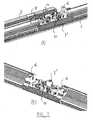
- FIG. 1shows a windscreen wiper device 1 of the "yokeless” type according to the invention.
- Said windscreen wiper deviceis built up of an elastomeric wiper blade 2, in the longitudinal sides of which opposing longitudinal grooves 3 are formed, and of longitudinal strips 4 made of spring band steel, which are fitted in said longitudinal grooves 3.
- Said strips 4form a flexible carrier element for the rubber wiper blade 2, as it were, which is thus biassed in a curved position (the curvature in operative position being that of a windscreen to be wiped).
- Neighbouring ends of strips 4are interconnected on either side of the windscreen wiper device 1 by means of connecting pieces 6 functioning as clamping members.
- the connecting pieces 6are separate constructional elements, which may be form-locked ("positive locking” or “having positive fit") as well as force-locked to the ends of strips 4.
- said connecting pieces 6are in one piece with the strips 4 made of spring band steel. In the latter case said connecting pieces form transverse bridges for the strips 4, as it were.
- a spoiler 5is furthermore provided.
- the windscreen wiper device 1is furthermore built up of a connecting device 7 of plastic material for an oscillating wiper arm 8.
- Said wiper arm 8is finalized by an extension (without an adapter).
- Connecting device 7consists of a first part 7' and a second part 7" detachably connected together.
- Said first part 7'is retained onto the wiperblade 2 and is positioned within said second part 7".
- said first part 7'comprises clamping members 9 that are integral therewith, which engage round longitudinal sides of the strips 4 that face away from each other, as a result of which the connecting device 7 is firmly attached to the unit consisting of wiper blade 2 and strips 4.
- Said second part 7"has a U-shaped cross-section at the location of its connection to said first part 7'.
- the oscillating wiper arm 8is pivotally connected to the connecting device 7 about a pivot axis near one end, and that in the following manner.
- said first part 7'comprises two cylindrical protrusions 10 extending outwards on either side of said second part 7'. These protrusions 10 pivotally engage in identically shaped cylindrical holes 11 of said second part 7". Said protrusions 10 act as bearing surfaces at the location of a pivot axis in order to pivot the second part 7" (and the oscillating wiper arm 8 attached thereto) about said pivot axis near one end of said arm 8.
- the protrusions 10are preferably in one piece with said first part 7'; in the alternative, the protrusions 10 are part of a single pivot pin perpendicular to the connecting device 7.
- the second part 7"comprises a protrusion 12 extending downwardly from a base of the U-shaped cross-secion of said second part 7", while the oscillating arm 8 has an identically shaped hole 13 with a closed circumference at the location of its connection to said second part 7", so that said protrusion 12 engages in said hole 13 ( figure 4 ).
- the interconnection between said second part 7" and said oscillating arm 8is done through a snapping operation, that is clipping the protrusion 12 into the hole 13.
- the protrusion 12 on said second part 7" and the hole 13 in the oscillating arm 8are meant for retaining the connecting device 7 onto the oscillating arm 8 and are therefore called “first retaining means".
- first retaining meanswould disfunction, for example when the protrusion 12 would not properly fit into the hole 13, the second part 7" and the first part 7' connected thereto would be able to move relative to the oscillating arm 8 in longitudinal direction of the wiper blade 2.
- second retaining meansare provided for.
- Said second retaining meansconsist of an upwardly extending protrusion 14 on said first part 7' cooperating with a second hole 15 having a open circumference in the oscillating arm 8.
- said protrusion 14engages into said correspondingly shaped hole 15 with an open circumference provided on a longitudinal side 16 of the oscillating arm 8.
- Said protrusion 14may also be called a cam.
- Figures 5 through 7refer to another preferred embodiment, wherein alternative second retaining means are shown in the sense that the first part 7' comprises an upwardly extending protrusion or cam 16 cooperating with a second hole 17 having a closed circumference in the oscillating arm 8.
- said protrusion 16engages into said correspondingly shaped hole 17 with a closed circumference.
- the second part 7" and thus the free end of the oscillating arm 8 connected theretois pivoted relative to the first part 7' ( figures 2A through 2C ). While carrying out the pivot movement the protrusion or cam 14,16 is no longer in line with the hole 13,17 and cannot mutually cooperate any longer, so that the second part 7" and the first part 7' attached thereto can be released from the oscillating arm 8. This can, of course, only be done when also the protrusion 12 in all embodiments is released from the hole 13.
- said first part 7' according to the first embodiment of figures 1 through 4 and said first part 7' according to the second embodiment of figures 5 through 7are mirror symmerical along a mid cross-sectional plane through said first parts 7'. Therefore, said second part 7" can be clipped onto said first part 7' irrespective of the orientation in longitudinal direction of said second part 7" relative to said first part 7'. Further, it is noted that both embodiments differ as far as said first part 7' is concerned, whereas said second part 7" with the downwardly extending protrusion 12 engaging into said correspondingly shaped hole 13 in the oscillating arm 8 is the same in both embodiments.
Landscapes
- Engineering & Computer Science (AREA)
- Mechanical Engineering (AREA)
- Pivots And Pivotal Connections (AREA)
- Cleaning In General (AREA)
Description
- The present invention relates to a windscreen wiper device comprising an elastic, elongated carrier element, as well as an elongated wiper blade of a flexible material, which can be placed in abutment with a windscreen to be wiped, which wiper blade includes opposing longitudinal grooves on its longitudinal sides, in which grooves spaced-apart longitudinal strips of the carrier element are disposed, wherein neighbouring ends of said longitudinal strips are interconnected by a respective connecting piece, which windscreen wiper device comprises a connecting device for an oscillating arm, wherein said oscillating arm is pivotally connected to said connecting device about a pivot axis near one end.
- Such a windscreen wiper device is generally known. This prior art windscreen wiper device is designed as a "yokeless" wiper device, wherein no use is made of several yokes pivotally connected to each other, but wherein the wiper blade is biassed by the carrier element, as a result of which it exhibits a specific curvature.
- In practice it has become apparent that, during use of the known windscreen wiper device, high forces ara exerted on the connection between the connecting device and the oscillating arm. As a consequence thereof the wiper blade may get loose from the oscillating arm.
- The object of the invention is to provide a windscreen wiper device, wherein the connecting device and the oscillating arm are connected in an improved manner, using a minimum of parts.
- Thereto, a windscreen wiper device of the type referred to in the introduction is characterized according to the invention in that said connecting device comprises at least two parts provided with protrusion/hole means for detachably connecting said parts together, wherein the first part is retained onto the wiper blade and wherein the second part has an at least substantially U-shaped cross-section at the location of its connection to said first part, wherein said windscreen wiper device is provided with first and second retaining means for retaining said connecting device onto said ocillating arm, wherein said first retaining means comprises at least one first protrusion on the second part engaging in a correspondingly shaped hole provided in said oscillating arm, and wherein said second retaining means comprise at least one second protrusion provided on the first part engaging the oscillating arm, said first part being positioned within said U-shaped second part. Particularly, said first protrusion engages into a correspondingly shaped hole with a closed circumference provided on the oscillating arm. More in particular, said first protrusion engages into a correspondingly shaped hole with an open circumference provided on a longitudinal side of the oscillating arm. Even more in particular, said first protrusion engages into a correspondingly shaped recess provided on the oscillating arm.
German patent publication no. 103 40 139 (Bosch ) describes a windscreen wiper device of the "flat blade" type according to the preamble of claim 1. The connecting device of this known windscreen wiper device comprises two parts (20,38), wherein the first part (20) is retained onto a wiper blade (14) and wherein the second part (38) is detachably connected to the first part (20). Said first part (20) has a guiding rib (30) extending in longitudinal direction which, in use, engages inside a hollow of a chamber (50) (German: "Kulisse") on said second part (38). In use, said chamber (50) engages inside a longitudinal hole (68) of an oscillating arm (66).- Preferably, the first protrusion is designed as a resilient tongue snappingly engaging into said correspondingly shaped hole of the oscillating arm. In that case, the first protrusion is movable along a hinge axis between a first position retaining the oscillating arm onto the connecting device and a second position releasing the oscillating arm from the connecting device. Said hinge axis is facing towards the free end of the oscillating arm or is facing away from the free end of the oscillating arm, all relative to the resilient tongue.
- In one preferred embodiment of a windscreen wiper device in accordance with the invention said second protrusion engages into a correspondingly shaped hole with a closed circumference provided on the oscillating arm. In the alternative, said second protrusion engages into a correspondingly shaped hole with an open circumference provided on a longitudinal side of the oscillating arm.
- In another preferred ebodiment of a windscreen wiper device according to the invention said second protrusion engages into a correspondingly shaped recess provided on the oscillating arm.
- In another preferred ebodiment of a windscreen wiper device in accordance with the invention said first protrusion extends downwardly from a base of the U-shaped cross-section of said second part.
- In another preferred embodiment of a windscreen wiper device in accordance with the invention said second protrusion extends upwardly from said first part.
- In another preferred ebodiment of a windscreen wiper device according to the invention said first part comprises engaging members made integral therewith for engaging around the longitudinal sides of the longitudinal strips that face away from each other. In other words, the engaging members each form a groove for introducing the longitudinal strips therein, so that the first part of the connecting device is firmly retained onto the wiper blade. In order to enhance the retention thereof the the engaging members may be welded, soldered, brazed or glued to the longitudinal strips.
- The invention will now be explained in more detail with reference to figures illustrated in a drawing, wherein
Figures 1 and2 show various successive steps for fitting together a connecting device and an oscillating arm of a windscreen wiper device according to the invention, whereinfigure 1 is a schematic, perspective view and whereinfigure 2 is a side view;Figure 3 is a perspective, schematic view of the oscillating arm offigure 1 connected to a first part of the connecting device offigure 1 ;Figure 4 refers to a perspective, schematic view of a second part of the connecting device offigure 1 ;Figures 5 through 7 correspond tofigures 1 through 4 , but now relating to a second embodiment of a windscreen wiper device in accordance with the invention.Figure 1 shows a windscreen wiper device 1 of the "yokeless" type according to the invention. Said windscreen wiper device is built up of anelastomeric wiper blade 2, in the longitudinal sides of which opposinglongitudinal grooves 3 are formed, and oflongitudinal strips 4 made of spring band steel, which are fitted in saidlongitudinal grooves 3. Saidstrips 4 form a flexible carrier element for therubber wiper blade 2, as it were, which is thus biassed in a curved position (the curvature in operative position being that of a windscreen to be wiped). Neighbouring ends ofstrips 4 are interconnected on either side of the windscreen wiper device 1 by means of connecting pieces 6 functioning as clamping members. In this embodiment, the connecting pieces 6 are separate constructional elements, which may be form-locked ("positive locking" or "having positive fit") as well as force-locked to the ends ofstrips 4. In another preferred variant, said connecting pieces 6 are in one piece with thestrips 4 made of spring band steel. In the latter case said connecting pieces form transverse bridges for thestrips 4, as it were. Possibly, aspoiler 5 is furthermore provided.- The windscreen wiper device 1 is furthermore built up of a connecting
device 7 of plastic material for an oscillatingwiper arm 8. Saidwiper arm 8 is finalized by an extension (without an adapter). Connectingdevice 7 consists of a first part 7' and asecond part 7" detachably connected together. Said first part 7' is retained onto thewiperblade 2 and is positioned within saidsecond part 7". Further, said first part 7' comprises clampingmembers 9 that are integral therewith, which engage round longitudinal sides of thestrips 4 that face away from each other, as a result of which the connectingdevice 7 is firmly attached to the unit consisting ofwiper blade 2 andstrips 4. Saidsecond part 7" has a U-shaped cross-section at the location of its connection to said first part 7'. The oscillatingwiper arm 8 is pivotally connected to the connectingdevice 7 about a pivot axis near one end, and that in the following manner. - With reference to
figures 1 and2 said first part 7' comprises twocylindrical protrusions 10 extending outwards on either side of said second part 7'. Theseprotrusions 10 pivotally engage in identically shapedcylindrical holes 11 of saidsecond part 7". Saidprotrusions 10 act as bearing surfaces at the location of a pivot axis in order to pivot thesecond part 7" (and the oscillatingwiper arm 8 attached thereto) about said pivot axis near one end of saidarm 8. Theprotrusions 10 are preferably in one piece with said first part 7'; in the alternative, theprotrusions 10 are part of a single pivot pin perpendicular to the connectingdevice 7. - Referring to
figures 3 and4 , thesecond part 7" comprises aprotrusion 12 extending downwardly from a base of the U-shaped cross-secion of saidsecond part 7", while theoscillating arm 8 has an identicallyshaped hole 13 with a closed circumference at the location of its connection to saidsecond part 7", so that saidprotrusion 12 engages in said hole 13 (figure 4 ). The interconnection between saidsecond part 7" and said oscillatingarm 8 is done through a snapping operation, that is clipping theprotrusion 12 into thehole 13. - The
protrusion 12 on saidsecond part 7" and thehole 13 in the oscillatingarm 8 are meant for retaining the connectingdevice 7 onto the oscillatingarm 8 and are therefore called "first retaining means". However, in case the first retaining means would disfunction, for example when theprotrusion 12 would not properly fit into thehole 13, thesecond part 7" and the first part 7' connected thereto would be able to move relative to the oscillatingarm 8 in longitudinal direction of thewiper blade 2. In order to avoid thewiper blade 2 from coming loose, with all negative consequences involved, second retaining means are provided for. Said second retaining means consist of an upwardly extendingprotrusion 14 on said first part 7' cooperating with asecond hole 15 having a open circumference in the oscillatingarm 8. In other words, saidprotrusion 14 engages into said correspondingly shapedhole 15 with an open circumference provided on alongitudinal side 16 of the oscillatingarm 8. Saidprotrusion 14 may also be called a cam. Figures 5 through 7 refer to another preferred embodiment, wherein alternative second retaining means are shown in the sense that the first part 7' comprises an upwardly extending protrusion orcam 16 cooperating with asecond hole 17 having a closed circumference in the oscillatingarm 8. In other words, saidprotrusion 16 engages into said correspondingly shapedhole 17 with a closed circumference.- For mounting or dismounting the connecting
device 7 onto or from theoscillating arm 8, thesecond part 7" and thus the free end of the oscillatingarm 8 connected thereto is pivoted relative to the first part 7' (figures 2A through 2C ). While carrying out the pivot movement the protrusion orcam hole second part 7" and the first part 7' attached thereto can be released from the oscillatingarm 8. This can, of course, only be done when also theprotrusion 12 in all embodiments is released from thehole 13. - It is noted that said first part 7' according to the first embodiment of
figures 1 through 4 and said first part 7' according to the second embodiment offigures 5 through 7 are mirror symmerical along a mid cross-sectional plane through said first parts 7'. Therefore, saidsecond part 7" can be clipped onto said first part 7' irrespective of the orientation in longitudinal direction of saidsecond part 7" relative to said first part 7'. Further, it is noted that both embodiments differ as far as said first part 7' is concerned, whereas saidsecond part 7" with the downwardly extendingprotrusion 12 engaging into said correspondingly shapedhole 13 in theoscillating arm 8 is the same in both embodiments. - The invention is not restricted to the variants shown in the drawing, but it also extends to other embodiments that fall within the scope of the claims. For example, a skilled person would easily recognize that instead of said
hole oscillating arm 8 could be used.
Claims (10)
- A windscreen wiper device (1) comprising an elastic, elongated carrier element, as well as an elongated wiper blade (2) of a flexible material, which can be placed in abutment with a windscreen to be wiped, which wiper blade (2) includes opposing longitudinal grooves (3) on its longitudinal sides, in which grooves (3) spaced-apart longitudinal strips (4) of the carrier element are disposed, wherein neighbouring ends of said longitudinal strips (4) are interconnected by a respective connecting piece (6), which windscreen wiper device(1) comprises a connecting device (7) for an oscillating arm (8), wherein said oscillating arm (8) is pivotally connected to said connecting device (7) about a pivot axis near one end and has a flat end, said connecting device (7) comprising at least two parts (7', 7") provided with protrusion/hole means for detachably connecting said parts (7', 7") together, wherein the first part (7') is retained onto the wiper blade (2) and wherein the second part (7") has an at least substantially U-shaped cross-section at the location of its connection to said first part (7'), wherein said windscreen wiper device (1) is provided with first and second retaining means for retaining said connecting device (7) onto said ocillating arm (8), wherein said first retaining means comprises at least one first protrusion (12) on the second part (7") engaging in a correspondingly shaped hole (13) provided in said oscillating arm (8), and wherein said second retaining means comprise at least one second protrusion (14, 16) provided on the first part (7') engaging the oscillating arm,characterized in that said first part (7') is positioned within said U-shaped second part (7").
- A windscreen wiper device (1) according claim 1, wherein said first protrusion (12) engages into a correspondingly shaped hole (13) with a closed circumference provided on the oscillating arm (8).
- A windscreen wiper device (1) according claim 1, wherein said first protrusion (12) engages into a correspondingly shaped hole (13) with an open circumference provided on a longitudinal side of the oscillating arm (8).
- A windscreen wiper device (1) according claim 1, wherein said first protrusion (12) engages into a correspondingly shaped recess provided on the oscillating arm (8).
- A windscreen wiper device (1) according to any of the preceding claims 1 through 4, wherein said second protrusion (16) engages into a correspondingly shaped hole (17) with a closed circumference provided on the oscillating arm (8).
- A windscreen wiper device (1) according to any of the preceding claims 1 through 4, wherein said second protrusion (14) engages into a correspondingly shaped hole (15) with an open circumference provided on a longitudinal side of the oscillating arm (8).
- A windscreen wiper device (1) according to any of the preceding claims 1 through 4, wherein said second protrusion (14, 16) engages into a correspondingly shaped recess provided on the oscillating arm (8).
- A windscreen wiper device (1) according to any of the preceding claims 1 through 7, wherein said first protrusion (12) extends downwardly from a base of the U-shaped cross-section of said second part (7").
- A windscreen wiper device (1) according to any of the preceding claims 1 through 8, wherein said second protrusion (14, 16) extends upwardly from said first part (7').
- A windscreen wiper device (1) according to any of the preceding claims 1 through 10, wherein said first part (7') comprises engaging members (9) made integral therewith for engaging around the longitudinal sides of the longitudinal strips (4) that face away from each other.
Priority Applications (7)
| Application Number | Priority Date | Filing Date | Title |
|---|---|---|---|
| ES06116695TES2332528T3 (en) | 2006-07-06 | 2006-07-06 | WINDSHIELD CLEANING DEVICE. |
| DE602006008768TDE602006008768D1 (en) | 2006-07-06 | 2006-07-06 | wiper device |
| EP06116695AEP1876074B1 (en) | 2006-07-06 | 2006-07-06 | Windshield wiper device |
| US12/307,651US20100017994A1 (en) | 2006-07-06 | 2007-07-02 | Windshield wiper device |
| JP2009517243AJP4972162B2 (en) | 2006-07-06 | 2007-07-02 | Windshield wiper device |
| PCT/EP2007/056646WO2008003678A1 (en) | 2006-07-06 | 2007-07-02 | Windshield wiper device |
| US13/759,883US8499408B2 (en) | 2006-07-06 | 2013-02-05 | Windshield wiper device |
Applications Claiming Priority (1)
| Application Number | Priority Date | Filing Date | Title |
|---|---|---|---|
| EP06116695AEP1876074B1 (en) | 2006-07-06 | 2006-07-06 | Windshield wiper device |
Publications (2)
| Publication Number | Publication Date |
|---|---|
| EP1876074A1 EP1876074A1 (en) | 2008-01-09 |
| EP1876074B1true EP1876074B1 (en) | 2009-08-26 |
Family
ID=37461761
Family Applications (1)
| Application Number | Title | Priority Date | Filing Date |
|---|---|---|---|
| EP06116695AActiveEP1876074B1 (en) | 2006-07-06 | 2006-07-06 | Windshield wiper device |
Country Status (6)
| Country | Link |
|---|---|
| US (2) | US20100017994A1 (en) |
| EP (1) | EP1876074B1 (en) |
| JP (1) | JP4972162B2 (en) |
| DE (1) | DE602006008768D1 (en) |
| ES (1) | ES2332528T3 (en) |
| WO (1) | WO2008003678A1 (en) |
Families Citing this family (23)
| Publication number | Priority date | Publication date | Assignee | Title |
|---|---|---|---|---|
| EP2236366B1 (en)* | 2009-04-02 | 2011-06-29 | Federal-Mogul S.A. | Windscreen wiper device |
| US20130227809A1 (en) | 2012-02-24 | 2013-09-05 | Pylon Manufacturing Corp. | Wiper blade |
| PL2670637T3 (en)* | 2011-02-02 | 2018-10-31 | Federal-Mogul S.A. | Windscreen wiper device |
| WO2012103947A1 (en) | 2011-02-03 | 2012-08-09 | Federal-Mogul S.A. | Windscreen wiper device |
| US9457768B2 (en) | 2011-04-21 | 2016-10-04 | Pylon Manufacturing Corp. | Vortex damping wiper blade |
| MX345011B (en) | 2011-07-28 | 2017-01-11 | Pylon Mfg Corp | Windshield wiper adapter, connector and assembly. |
| US9108595B2 (en) | 2011-07-29 | 2015-08-18 | Pylon Manufacturing Corporation | Windshield wiper connector |
| US20130219649A1 (en) | 2012-02-24 | 2013-08-29 | Pylon Manufacturing Corp. | Wiper blade |
| US10723322B2 (en) | 2012-02-24 | 2020-07-28 | Pylon Manufacturing Corp. | Wiper blade with cover |
| JP6037360B2 (en)* | 2012-05-14 | 2016-12-07 | フェデラル−モグル エス.エー.Federal−Mogul.S.A. | Windscreen wiper device |
| PL2882620T3 (en)* | 2012-08-13 | 2020-03-31 | Mitsuba Teklas Turkey Otomotiv Anonim Sirketi | A windscreen wiper |
| US10829092B2 (en) | 2012-09-24 | 2020-11-10 | Pylon Manufacturing Corp. | Wiper blade with modular mounting base |
| US10166951B2 (en) | 2013-03-15 | 2019-01-01 | Pylon Manufacturing Corp. | Windshield wiper connector |
| US9505380B2 (en) | 2014-03-07 | 2016-11-29 | Pylon Manufacturing Corp. | Windshield wiper connector and assembly |
| WO2017075066A1 (en) | 2015-10-26 | 2017-05-04 | Pylon Manufacturing Corp. | Wiper blade |
| EP3458315B1 (en) | 2016-05-19 | 2021-09-08 | Pylon Manufacturing Corp. | Windshield wiper blade |
| WO2017201485A1 (en) | 2016-05-19 | 2017-11-23 | Pylon Manufacturing Corp. | Windshield wiper connector |
| WO2017201470A1 (en) | 2016-05-19 | 2017-11-23 | Pylon Manufacturing Corp. | Windshield wiper connector |
| US11040705B2 (en) | 2016-05-19 | 2021-06-22 | Pylon Manufacturing Corp. | Windshield wiper connector |
| WO2017201458A1 (en) | 2016-05-19 | 2017-11-23 | Pylon Manufacturing Corp. | Windshield wiper connector |
| CN112912287B (en)* | 2018-08-27 | 2024-05-03 | 特瑞科比利时股份公司 | Flat-piece type windscreen wiper device |
| FR3113014B1 (en)* | 2020-07-30 | 2022-10-28 | Valeo Systemes Dessuyage | Connection device for a wiper system for a vehicle |
| FR3154683A1 (en)* | 2024-03-29 | 2025-05-02 | Valeo Systemes D'essuyage | Connector for wiper blade and wiping system |
Family Cites Families (7)
| Publication number | Priority date | Publication date | Assignee | Title |
|---|---|---|---|---|
| CN100548760C (en)* | 2002-04-04 | 2009-10-14 | 罗伯特-博希股份公司 | Having one scrapes water arm and one and is articulated in the Wiper crank that this scrapes the swept area of wiper blade on the water arm |
| DE10228494A1 (en)* | 2002-06-26 | 2004-01-15 | Robert Bosch Gmbh | Windscreen wiper blade has mounting with two walls attached to its top, bolt fitting through bore in this into adapter fitted with swiveling catch and wiper arm fitting into channel in its top |
| DE10340139B4 (en) | 2003-09-01 | 2017-03-23 | Robert Bosch Gmbh | articulation |
| DE20314551U1 (en)* | 2003-09-19 | 2005-01-27 | Robert Bosch Gmbh | Wiper lever for windscreen wiper system of motor vehicle has free end of wiper arm provided with rod-like end section for which is provided fitting channel in adaptor acting as connection between sections of wiper lever |
| EP1568559B2 (en)* | 2004-02-26 | 2013-08-21 | Federal-Mogul S.A. | A windscreen wiper device |
| ES2298684T3 (en)* | 2004-08-03 | 2008-05-16 | Federal-Mogul S.A. | A WINDSHIELD CLEANING DEVICE. |
| EP1681216B1 (en)* | 2005-01-14 | 2008-02-27 | Federal-Mogul S.A. | Windshield wiper device |
- 2006
- 2006-07-06DEDE602006008768Tpatent/DE602006008768D1/enactiveActive
- 2006-07-06ESES06116695Tpatent/ES2332528T3/enactiveActive
- 2006-07-06EPEP06116695Apatent/EP1876074B1/enactiveActive
- 2007
- 2007-07-02WOPCT/EP2007/056646patent/WO2008003678A1/enactiveApplication Filing
- 2007-07-02JPJP2009517243Apatent/JP4972162B2/ennot_activeExpired - Fee Related
- 2007-07-02USUS12/307,651patent/US20100017994A1/ennot_activeAbandoned
- 2013
- 2013-02-05USUS13/759,883patent/US8499408B2/enactiveActive
Also Published As
| Publication number | Publication date |
|---|---|
| JP4972162B2 (en) | 2012-07-11 |
| US20130145569A1 (en) | 2013-06-13 |
| JP2009542491A (en) | 2009-12-03 |
| EP1876074A1 (en) | 2008-01-09 |
| US20100017994A1 (en) | 2010-01-28 |
| WO2008003678A1 (en) | 2008-01-10 |
| DE602006008768D1 (en) | 2009-10-08 |
| ES2332528T3 (en) | 2010-02-08 |
| US8499408B2 (en) | 2013-08-06 |
Similar Documents
| Publication | Publication Date | Title |
|---|---|---|
| EP1876074B1 (en) | Windshield wiper device | |
| EP1681216B1 (en) | Windshield wiper device | |
| EP1849666B1 (en) | A windscreen wiper device | |
| EP1359073B1 (en) | Windscreen wiper device | |
| EP1847425B1 (en) | A windscreen wiper device | |
| EP1854685B1 (en) | A windscreen wiper device | |
| US20100275403A1 (en) | Windscreen wiper device | |
| EP3164304B1 (en) | A windscreen wiper device | |
| EP2670637B1 (en) | Windscreen wiper device | |
| EP1745998B1 (en) | Windscreen wiper device | |
| EP1564094B1 (en) | Windscreen wiper device | |
| EP3353018B1 (en) | Windscreen wiper device | |
| EP3416859B1 (en) | Windscreen wiper device | |
| EP1568558A1 (en) | Windscreen wiper device | |
| EP3749553B1 (en) | Windscreen wiper device |
Legal Events
| Date | Code | Title | Description |
|---|---|---|---|
| PUAI | Public reference made under article 153(3) epc to a published international application that has entered the european phase | Free format text:ORIGINAL CODE: 0009012 | |
| AK | Designated contracting states | Kind code of ref document:A1 Designated state(s):AT BE BG CH CY CZ DE DK EE ES FI FR GB GR HU IE IS IT LI LT LU LV MC NL PL PT RO SE SI SK TR | |
| AX | Request for extension of the european patent | Extension state:AL BA HR MK YU | |
| 17P | Request for examination filed | Effective date:20080702 | |
| AKX | Designation fees paid | Designated state(s):BE DE ES FR GB IT | |
| 17Q | First examination report despatched | Effective date:20080822 | |
| GRAP | Despatch of communication of intention to grant a patent | Free format text:ORIGINAL CODE: EPIDOSNIGR1 | |
| GRAS | Grant fee paid | Free format text:ORIGINAL CODE: EPIDOSNIGR3 | |
| GRAA | (expected) grant | Free format text:ORIGINAL CODE: 0009210 | |
| AK | Designated contracting states | Kind code of ref document:B1 Designated state(s):BE DE ES FR GB IT | |
| REG | Reference to a national code | Ref country code:GB Ref legal event code:FG4D | |
| REF | Corresponds to: | Ref document number:602006008768 Country of ref document:DE Date of ref document:20091008 Kind code of ref document:P | |
| REG | Reference to a national code | Ref country code:ES Ref legal event code:FG2A Ref document number:2332528 Country of ref document:ES Kind code of ref document:T3 | |
| PLBE | No opposition filed within time limit | Free format text:ORIGINAL CODE: 0009261 | |
| STAA | Information on the status of an ep patent application or granted ep patent | Free format text:STATUS: NO OPPOSITION FILED WITHIN TIME LIMIT | |
| 26N | No opposition filed | Effective date:20100527 | |
| GBPC | Gb: european patent ceased through non-payment of renewal fee | Effective date:20100706 | |
| PG25 | Lapsed in a contracting state [announced via postgrant information from national office to epo] | Ref country code:GB Free format text:LAPSE BECAUSE OF NON-PAYMENT OF DUE FEES Effective date:20100706 | |
| REG | Reference to a national code | Ref country code:ES Ref legal event code:FD2A Effective date:20110818 | |
| PG25 | Lapsed in a contracting state [announced via postgrant information from national office to epo] | Ref country code:ES Free format text:LAPSE BECAUSE OF NON-PAYMENT OF DUE FEES Effective date:20100707 | |
| REG | Reference to a national code | Ref country code:FR Ref legal event code:PLFP Year of fee payment:11 | |
| REG | Reference to a national code | Ref country code:FR Ref legal event code:PLFP Year of fee payment:12 | |
| REG | Reference to a national code | Ref country code:FR Ref legal event code:PLFP Year of fee payment:13 | |
| PGFP | Annual fee paid to national office [announced via postgrant information from national office to epo] | Ref country code:BE Payment date:20180719 Year of fee payment:13 | |
| REG | Reference to a national code | Ref country code:BE Ref legal event code:MM Effective date:20190731 | |
| PG25 | Lapsed in a contracting state [announced via postgrant information from national office to epo] | Ref country code:BE Free format text:LAPSE BECAUSE OF NON-PAYMENT OF DUE FEES Effective date:20190731 | |
| PGFP | Annual fee paid to national office [announced via postgrant information from national office to epo] | Ref country code:DE Payment date:20240729 Year of fee payment:19 | |
| PGFP | Annual fee paid to national office [announced via postgrant information from national office to epo] | Ref country code:FR Payment date:20240725 Year of fee payment:19 | |
| PGFP | Annual fee paid to national office [announced via postgrant information from national office to epo] | Ref country code:IT Payment date:20240719 Year of fee payment:19 |