EP1875333B1 - System and method for training a trainable transmitter and a remote control system receiver - Google Patents
System and method for training a trainable transmitter and a remote control system receiverDownload PDFInfo
- Publication number
- EP1875333B1 EP1875333B1EP06750418AEP06750418AEP1875333B1EP 1875333 B1EP1875333 B1EP 1875333B1EP 06750418 AEP06750418 AEP 06750418AEP 06750418 AEP06750418 AEP 06750418AEP 1875333 B1EP1875333 B1EP 1875333B1
- Authority
- EP
- European Patent Office
- Prior art keywords
- control signal
- transmitter
- trainable transmitter
- control system
- remote control
- Prior art date
- Legal status (The legal status is an assumption and is not a legal conclusion. Google has not performed a legal analysis and makes no representation as to the accuracy of the status listed.)
- Active
Links
Images


Classifications
- G—PHYSICS
- G08—SIGNALLING
- G08C—TRANSMISSION SYSTEMS FOR MEASURED VALUES, CONTROL OR SIMILAR SIGNALS
- G08C19/00—Electric signal transmission systems
- G08C19/16—Electric signal transmission systems in which transmission is by pulses
- G08C19/28—Electric signal transmission systems in which transmission is by pulses using pulse code
- G—PHYSICS
- G08—SIGNALLING
- G08C—TRANSMISSION SYSTEMS FOR MEASURED VALUES, CONTROL OR SIMILAR SIGNALS
- G08C2201/00—Transmission systems of control signals via wireless link
- G08C2201/20—Binding and programming of remote control devices
- G—PHYSICS
- G08—SIGNALLING
- G08C—TRANSMISSION SYSTEMS FOR MEASURED VALUES, CONTROL OR SIMILAR SIGNALS
- G08C2201/00—Transmission systems of control signals via wireless link
- G08C2201/30—User interface
- G08C2201/31—Voice input
- G—PHYSICS
- G08—SIGNALLING
- G08C—TRANSMISSION SYSTEMS FOR MEASURED VALUES, CONTROL OR SIMILAR SIGNALS
- G08C2201/00—Transmission systems of control signals via wireless link
- G08C2201/60—Security, fault tolerance
- G08C2201/62—Rolling code
- G—PHYSICS
- G08—SIGNALLING
- G08C—TRANSMISSION SYSTEMS FOR MEASURED VALUES, CONTROL OR SIMILAR SIGNALS
- G08C2201/00—Transmission systems of control signals via wireless link
- G08C2201/90—Additional features
- G08C2201/92—Universal remote control
Definitions
- the present inventionrelates generally to the field of trainable transmitters or transceivers for use with vehicles. More specifically, the present invention relates to trainable transmitters that are configured for use with remote control systems.
- Electronically operated remote control systemsas for example disclosed in US 5661804 A or US 2005/026604A1 , such as garage door opener systems, home security systems, home lighting systems, gate controllers, etc., typically employ a portable, haad-held transmitters (i.e., an original transmitter) to transmit a control signal to a receiver located at the remote control system.
- a garage door opener systemtypically includes a receiver located within a home owner's garage and coupled to the garage door opener. A user presses a button on the original transmitter to transmit a radio frequency signal to the receiver to activate the garage door opener to open and close a garage door.
- the receiveris tuned to the frequency of its associated original transmitter and demodulates a predetermined code programmed into both the original transmitter and the receiver for operating the garage door.
- manufacturerscommonly use encryption technology to encrypt the radio frequency signal sent from a transmitter to a receiver.
- One such encryption methodis a rolling code system, wherein each digital message sent from the transmitter to the receiver has a different code from the previous digital message. .
- a trainable transmitter or transceivermay be provided in a vehicle for use with remote control systems.
- a trainable transmitteris configurable by a user to activate one or more of a plurality of different remote control system receivers using different radio frequency messages.
- training a trainable transmitter to an existing original transmitteris a two-step process. First, a user holds the two transmitters in close range and presses buttons on the original transmitter and the trainable transmitter. The trainable transmitter identifies the type of remote control system associated with the original transmitter based on a radio frequency signal received from the original transmitter.
- the trainable transmittermay identify and store the control code and RF carrier frequency of the original transmitter radio frequency control signal
- the receivermay learn a transmitter identifier of the trainable transmitter.
- the trainable transceiver and receivermust also be "synchronized" so that the counters of the trainable transmitter and the receiver begin at the same value. Accordingly, the user presses a button on the receiver to put the receiver in a training mode. A button on the trainable transceiver may then be pressed, for example, two to three times, within a set period of time to transmit messages so the receiver may learn the transmitter identifier, complete synchronization of the receiver and the trainable transmitter and confirm that training was successful. Once trained, the trainable transmitter may be used to transmit RF signals to control the remote control system.
- the second step of the training processrequires a user to put the receiver of the remote control system in a training mode. Accordingly, the user may need to climb a ladder to press a button on the remote control system receiver and then return to a vehicle to press a button of the trainable transmitter within a set period of time.
- a usermay also not know that their remote control system (e.g., a garage door opener system) is a rolling code system and therefore requires the second step of the training process. Accordingly, the user may not perform the second step and the trainable transmitter will not operate the remote control system.
- a method for training a trainable transmitterincludes receiving a request to enter a training mode from a user, beginning a training mode in response to the request to enter a training mode, receiving a control signal from an original transmitter associated with a remote control system, detecting a frequency and control data of the control signal, the control data including a fixed portion and an encrypted portion, identifying rolling code data associated with the remote control system, generating a learn message based on the fixed portion and encrypted portion of the control signal, the learn message configured to cause a receiver of the remote control system to enter a training mode, receiving a request to transmit the learn message from a user, transmitting the learn message to the remote control system for a predetermined period of time, generating a rolling code control signal using the identified rolling code data upon expiration of the predetermined period of time, and transmitting the rolling code control signal to the remote control system.
- a trainable transmitterfor mounting in a vehicle and for communicating with a remote control system associated with an original transmitter
- the trainable transmitterincludes a control circuit, a receiver circuit communicably coupled to the control circuit and configured to receive a control signal from the original transmitter, wherein the control circuit is configured to identify an encrypted portion of the control signal, and wherein the control circuit is further configured to generate a learn message based on at least the encrypted portion of the control signal and an identifier of the trainable transmitter; and a transmitter circuit communicably coupled to the control circuit and configured to transmit the learn message to the remote control system, wherein the control circuit is configured to generate a rolling code control signal, and wherein the transmitter circuit is configured to transmit the rolling code control signal to the remote control system, wherein the rolling code control signal is configured to cause actuation of the remote control system; wherein the learn message is configured to cause the remote control system to calculate information that the remote control system will expect to receive with the rolling code control signal, wherein the rolling code control signal includes the identifier associated with the trainable
- FIG. 1is a perspective view of a vehicle having a trainable transmitter in accordance with an embodiment.
- FIG. 2is a schematic block diagram of a trainable transmitter in accordance with an embodiment.
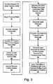
- FIG. 3illustrates a method of training a trainable transmitter in accordance with an embodiment.
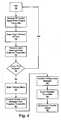
- FIG. 4illustrates a method of training a receiver of a remote control system in accordance with an embodiment.
- FIG. 1is a perspective view of a vehicle including a trainable transmitter in accordance with an embodiment.
- a vehicle 10which may be an automobile, truck, sport utility vehicle (SUV), mini-van, or other vehicle, includes a trainable transmitter 16.
- a trainable transmittermay be embodied in other systems such as a portable housing, key fob, key chain or other hand-held device.
- trainable transmitter 16is illustrated mounted to an overhead console of vehicle 10.
- one or more of the elements of trainable transmitter 16may be mounted to other vehicle interior elements such as a visor 17, an instrument panel 18, a rearview mirror (not shown), a dashboard, seat, center console, door panel, or other appropriate location in the vehicle.
- Trainable transmitter 16may be configured to control a remote control system 14, such as a garage door opener, home security system, home lighting system, gate controller, etc. Trainable transmitter 16 is trained using an original transmitter 12 used to control remote control system 14.
- Original transmitter 12is a transmitter, typically a hand-held transmitter, which is sold with remote control system 14 or as an after-market item, and which is configured to transmit an activation signal at a predetermined carrier frequency and having control data configured to actuate remote control system 14.
- original transmitter 12can be a hand-held garage door opener transmitter configured to transmit a garage door opener signal at a frequency, such as 355 Megahertz (MHz), wherein the activation signal has control data, which can be fixed code or cryptographically-encoded code (e.g., a rolling code).
- remote control system 14may be a garage door opener system configured to open a garage door in response to receiving the activation signal from original transmitter 12. Accordingly, remote control system 14 includes an antenna (not shown) for receiving wireless signals including control data which would control remote control system 14.
- an activation or control signal Ais transmitted from original transmitter 12 to trainable transmitter 16 in the vehicle 10.
- Trainable transmitter 16receives the control signal, identifies the control data (e.g., fixed or rolling code data) and carrier frequency of the control signal and stores this information.
- Trainable transmitter 16may then be used to selectively generate a control signal T based on the learned frequency and control data and to transmit the control signal T to the remote control system 14, such as a garage door opener, that is responsive to the control signal.
- the remote control system 14such as a garage door opener
- FIG. 2is a schematic block diagram of a trainable transmitter in accordance with an embodiment.
- Transmitter 16includes a transmitter circuit 20 and a receiver 21 that are coupled to an antenna 38.
- a single dual function transceiver having transmit and receive circuitrymay be provided in place of a separate receiver and transmitter.
- Transmitter circuit 20 and receiver 21are also coupled to a control circuit 22.
- Control circuit 22may include various types of control circuitry, digital and/or analog, and may include a microprocessor, microcontroller, application specific integrated circuit (ASIC), or other digital and/or analog circuitry configured to perform various input/output, control, analysis, and other functions to be described herein.
- a switch interface 24is coupled to a plurality of buttons or switches.
- switch interface 24is coupled to one terminal of each of three push button switches 26, 28 and 30, which have their remaining terminal connected to ground.
- Switches 26, 28 and 30may each be associated with a separate remote control system to be controlled, each of which may have its own unique operating RF frequency, modulation scheme, and/or control data.
- switches 26, 28 and 30each correspond to a different radio frequency channel for transmitter circuit 20. It should be understood, however, that each channel may be trained to the same original transmitter, if desired, or to different original transmitters.
- Interlace circuit 24couples signal information from switches 26, 28 and 30 to the input terminals of control circuit 22.
- Control circuit 22includes data input terminals for receiving signals from the switch interface 24 indicative of the closure states of switches 26, 28 and 30.
- a power supply 32is conventionally coupled to the various components for supplying the necessary operating power in a conventional manner.
- Control circuit 22is also coupled to a display 36 which includes a display element such as a light emitting diode (LED).
- Display 36may alternatively include, for example, a liquid crystal display (LCD), a vacuum fluorescent display (VFD), or other display elements.
- Control circuit 22includes a memory 34 including volatile and/or non-volatile memory to, for example, store a computer program or other software to perform the functions described herein.
- Memory 34is configured to store learned information such as control data and carrier frequency information that may be associated with switches 26, 28 and 30.
- each switch or button 26, 28 and 30may be associated with a separate remote control system, such as different garage door openers, electronically operated access gates, house lighting controls and other remote control systems, each which may have its own unique operating RF frequency, modulation scheme, encryption(or cryptographic) algorithm and control data.
- Transmitter circuit 20 and receiver 21communicate with the remote control system 14 and the original transmitter 12 via antenna 38.
- Receiver 21may be used to receive signals via antenna 38 and transmitter circuit 20 may be used to transmit signals via antenna 38.
- a separate antennamay be used with transmitter 20 and with receiver 21 (e.g., separate transmit and receive antennas may be provided in the trainable transmitter).
- Remote control system 14includes a receiver 15 to receive signals such as an RF control signal from, for example, original transmitter 12 or trainable transmitter 16. Once a channel of trainable transmitter 16 has been trained, trainable transmitter 16 is configured to transmit a wireless control signal having control data that will control remote control system 14.
- transmitter circuit 20in response to actuation of a switch such as switch 26, is configured, under control from control circuit 22, to generate a control signal having a carrier frequency and control data associated with the particular trained channel.
- the control datamay be modulated onto the control signal using, for example, frequency shift key (FSK) modulation, amplitude shift key (ASK) modulation or other modulation technique.
- the control data on the control signalmay be a rolling code or other cryptographically encoded control code suitable for use with remote control system 14.
- the rolling code or cryptographic algorithm for remote control system 14may be identified by trainable transmitter 16 using the control signal (e.g., the carrier frequency and control data) of original transmitter 12.
- Figure 3illustrates a method for training a trainable transmitter in accordance with an embodiment.
- Both the trainable transmitter and the original transmitterare brought within range of the remote control system (e.g., a garage door opener system).
- a request to enter a training modeis received from a user at the trainable transmitter.
- a usermay provide a request by actuating a pushbutton (e.g., pushbutton 26 in Figure 2 ) of the trainable transmitter.
- the userholds the pushbutton until feedback is provided that the training of the channel is complete.
- the usermay hold the pushbutton for a predetermined amount of time (e.g., 3 seconds, 10 seconds, etc.).
- a displaymay be used to indicate to the user that a training mode was initiated, for example, a display element such as an LED indicator may flash to provide feedback to a user.
- the display elementmay be used to indicate that the channel is trained (e.g., a LED may flash rapidly).
- a request to enter a training modemay be provided by a combination of key presses using input devices of the trainable transmitter, by receiving a message on a vehicle bus, upon receipt of a control signal from the original transmitter or by selecting a menu item on a display.
- the trainable transmitterenters a training mode and begins looking for a control signal to train the channel.
- an original transmitter for a remote control systeme.g., original transmitter 12 in Figure 2
- an RF control signalfor example, a control signal with a rolling code.
- the trainable transmitterreceives the RF control signal from the original transmitter.
- the remote control systemwhich is also within range of the original transmitter, receives the RF control signal from the original transmitter at block 71 shown in Figure 4.
- Figure 4illustrates a method for training a receiver of a remote control system in accordance with an embodiment.
- the remote control system receiver(e.g., receiver 15 shown in Figure 2 ) starts a window of time in which it will receive and accept a learn message from the trainable transmitter.
- the window of timemay be, for example, 30 to 45 seconds.
- a remote control systemsuch as a garage door opener, may be configured to close the learn window before expiration of the time period if, for example, a photo beam at the bottom of the garage is broken. This may be an indication that a vehicle is entering or exiting the garage and that it is likely a user is not attempting to train a trainable transmitter.
- the, trainable transmitterdetects and identifies a carrier frequency and control data of the received RF control signal at block 48.
- the trainable transmittermay receive the rolling code signal from the original transmitter, demodulate the control signal and identify the control data and carrier frequency of the control signal.
- the carrier frequency and control datamay be stored in memory.
- the control data of the encrypted rolling code signalmay include a transmitter identifier (e.g., a serial number) and an encrypted counter value (or a hop code).
- a counter value in the original transmitterincrements each time the button is pressed and is encrypted using an encryption algorithm to generate the encrypted counter value of the control signal.
- the carrier frequency and control datamay be used to identify the type of remote control system (e.g., the manufacturer) associated with the original transmitter.
- Rolling code datae.g., an encryption algorithm and carrier frequency or frequencies
- this informationmay be used to generate appropriate control signals (e.g., an appropriate rolling code signal) in response to subsequent actuation of an input device of the trainable transmitter associated with the trained channel.
- the trainable transmittere.g., a control circuit 22 of the trainable transmitter shown in Figure 2
- the learn messageis generated based on at least the encrypted portion (e.g., the encrypted counter value) of the original transmitter control signal.
- the unencrypted portione.g., the transmitter identifier for the original transmitter
- the control signalmay also be used to generate the learn message.
- a transmitter identifier for the trainable transmittere.g., a serial number for the trainable transmitter
- the learn messageis generated by applying a predetermined algorithm to the encrypted portion of the control signal in its encrypted form (e:g., an encrypted counter value that has not been decrypted) and the transmitter identifier (e.g., the fixed portion of the control signal) of the original transmitter.
- the learn messagemay, for example, represent an initial rolling count for the trainable transmitter.
- the learn messagemay also include the transmitter identifier (e.g., a serial number) of the trainable transmitter.
- the learn messagemay include a value generated by performing an exclusive-OR (XOR) or addition between the encrypted portion of the original transmitter control signal and the transmitter identifier of the trainable transmitter.
- XORexclusive-OR
- predetermined algorithmsmay be used to generate the learn message based on the original transmitter control signal (e.g., the fixed and encrypted portions of the original transmitter control signal) and are within the scope of the appended claims.
- a predetermined algorithmmay be applied to the transmitter identifier and the encrypted counter value (in its encrypted form) of the original transmitter control signal.
- the learn message generatedis a fixed message, for example, a 32-bit fixed word.
- the learn messagemay include a fixed portion and an encrypted portion (e.g., a portion of the learn message may be encrypted using an encryption algorithm).
- a userprovides input (e.g., by actuating the pushbutton associated with the trained channel) to initiate transmission of the learn message to the remote control system receiver at block 58.
- the learn messageis transmitted for a predetermined period of time.
- the learn messagemay be transmitted for one second or several seconds.
- the trainable transmittermay be configured to transmit the learn message for the duration of time the user is holding the button down.
- the trainable transmitterUpon expiration of the predetermined period of time (or upon the next button push), the trainable transmitter generates a rolling code control signal using the rolling code data (e.g., an encryption algorithm and carrier frequency) associated with the trained channel and transmits the rolling code control signal to the remote control system at block 60.
- the rolling code datae.g., an encryption algorithm and carrier frequency
- the remote control system receiverreceives the learn message from the trainable transmitter.
- a receivere.g., receiver 15 show in Figure 2
- the remote control system receiveris configured to identify a learn message generated with the predetermined algorithm. If the window of time has expired at block 76, the remote control system receiver returns to an idle state 70 and waits for another transmission from an original transmitter. If the window of time triggered by receipt of the original transmitter control signal (described above) has not expired at block 76, the remote control system receiver enters a training (or enrollment) mode in response to the learn message at block 80.
- the remote control system receiverreceives the rolling code control signal transmitted from the trainable transmitter. In response to the rolling code control signal, the receiver enrolls the trainable transmitter as a valid transmitter at block 84.
- the steps described above with reference to blocks 80 and 82may be implemented to provide additional security.
- the learn message transmitted at block 80may be configured to incorporate some portion of the rolling code control signal transmitted at block 82, such as the serial number.
- the remote control system receivermay open the learn window and receive a rolling code control signal transmitted at step 82 having the specific serial number transmitted in step 80.
- the messagemay be validated as shown at block 83.
- the receivermay store the serial number of the trainable transmitter and identify the trainable transmitter as a valid transmitter.
- the counter values of the trainable transmitter and the remote control systemare synchronized at block 86.
Landscapes
- Physics & Mathematics (AREA)
- General Physics & Mathematics (AREA)
- Selective Calling Equipment (AREA)
Description
- The present invention relates generally to the field of trainable transmitters or transceivers for use with vehicles. More specifically, the present invention relates to trainable transmitters that are configured for use with remote control systems.
- Electronically operated remote control systems as for example disclosed in
US 5661804 A orUS 2005/026604A1 , such as garage door opener systems, home security systems, home lighting systems, gate controllers, etc., typically employ a portable, haad-held transmitters (i.e., an original transmitter) to transmit a control signal to a receiver located at the remote control system. For example, a garage door opener system typically includes a receiver located within a home owner's garage and coupled to the garage door opener. A user presses a button on the original transmitter to transmit a radio frequency signal to the receiver to activate the garage door opener to open and close a garage door. Accordingly, the receiver is tuned to the frequency of its associated original transmitter and demodulates a predetermined code programmed into both the original transmitter and the receiver for operating the garage door. To enhance security of wireless control systems, such as a garage door opener system, manufacturers commonly use encryption technology to encrypt the radio frequency signal sent from a transmitter to a receiver. One such encryption method is a rolling code system, wherein each digital message sent from the transmitter to the receiver has a different code from the previous digital message. . - As an alternative to a portable, hand-held original transmitter, a trainable transmitter or transceiver may be provided in a vehicle for use with remote control systems. A trainable transmitter is configurable by a user to activate one or more of a plurality of different remote control system receivers using different radio frequency messages. Typically, training a trainable transmitter to an existing original transmitter is a two-step process. First, a user holds the two transmitters in close range and presses buttons on the original transmitter and the trainable transmitter. The trainable transmitter identifies the type of remote control system associated with the original transmitter based on a radio frequency signal received from the original transmitter. For example, the trainable transmitter may identify and store the control code and RF carrier frequency of the original transmitter radio frequency control signal, Second, the receiver may learn a transmitter identifier of the trainable transmitter. For systems employing a rolling code (or other encryption method), the trainable transceiver and receiver must also be "synchronized" so that the counters of the trainable transmitter and the receiver begin at the same value. Accordingly, the user presses a button on the receiver to put the receiver in a training mode. A button on the trainable transceiver may then be pressed, for example, two to three times, within a set period of time to transmit messages so the receiver may learn the transmitter identifier, complete synchronization of the receiver and the trainable transmitter and confirm that training was successful. Once trained, the trainable transmitter may be used to transmit RF signals to control the remote control system.
- As mentioned, the second step of the training process requires a user to put the receiver of the remote control system in a training mode. Accordingly, the user may need to climb a ladder to press a button on the remote control system receiver and then return to a vehicle to press a button of the trainable transmitter within a set period of time. A user may also not know that their remote control system (e.g., a garage door opener system) is a rolling code system and therefore requires the second step of the training process. Accordingly, the user may not perform the second step and the trainable transmitter will not operate the remote control system.
- In accordance with an embodiment, a method for training a trainable transmitter includes receiving a request to enter a training mode from a user, beginning a training mode in response to the request to enter a training mode, receiving a control signal from an original transmitter associated with a remote control system, detecting a frequency and control data of the control signal, the control data including a fixed portion and an encrypted portion, identifying rolling code data associated with the remote control system, generating a learn message based on the fixed portion and encrypted portion of the control signal, the learn message configured to cause a receiver of the remote control system to enter a training mode, receiving a request to transmit the learn message from a user, transmitting the learn message to the remote control system for a predetermined period of time, generating a rolling code control signal using the identified rolling code data upon expiration of the predetermined period of time, and transmitting the rolling code control signal to the remote control system.
- In accordance with another embodiment, a trainable transmitter for mounting in a vehicle and for communicating with a remote control system associated with an original transmitter, the trainable transmitter includes a control circuit, a receiver circuit communicably coupled to the control circuit and configured to receive a control signal from the original transmitter, wherein the control circuit is configured to identify an encrypted portion of the control signal, and wherein the control circuit is further configured to generate a learn message based on at least the encrypted portion of the control signal and an identifier of the trainable transmitter; and a transmitter circuit communicably coupled to the control circuit and configured to transmit the learn message to the remote control system, wherein the control circuit is configured to generate a rolling code control signal, and wherein the transmitter circuit is configured to transmit the rolling code control signal to the remote control system, wherein the rolling code control signal is configured to cause actuation of the remote control system; wherein the learn message is configured to cause the remote control system to calculate information that the remote control system will expect to receive with the rolling code control signal, wherein the rolling code control signal includes the identifier associated with the trainable transmitter and a new encrypted portion.
FIG. 1 is a perspective view of a vehicle having a trainable transmitter in accordance with an embodiment.FIG. 2 is a schematic block diagram of a trainable transmitter in accordance with an embodiment.FIG. 3 illustrates a method of training a trainable transmitter in accordance with an embodiment.FIG, 4 illustrates a method of training a receiver of a remote control system in accordance with an embodiment.Figure 1 is a perspective view of a vehicle including a trainable transmitter in accordance with an embodiment. Avehicle 10, which may be an automobile, truck, sport utility vehicle (SUV), mini-van, or other vehicle, includes atrainable transmitter 16. In alternative embodiments, a trainable transmitter may be embodied in other systems such as a portable housing, key fob, key chain or other hand-held device. InFigure 1 ,trainable transmitter 16 is illustrated mounted to an overhead console ofvehicle 10. Alternatively, one or more of the elements oftrainable transmitter 16 may be mounted to other vehicle interior elements such as avisor 17, aninstrument panel 18, a rearview mirror (not shown), a dashboard, seat, center console, door panel, or other appropriate location in the vehicle.Trainable transmitter 16 may be configured to control aremote control system 14, such as a garage door opener, home security system, home lighting system, gate controller, etc.Trainable transmitter 16 is trained using anoriginal transmitter 12 used to controlremote control system 14.Original transmitter 12 is a transmitter, typically a hand-held transmitter, which is sold withremote control system 14 or as an after-market item, and which is configured to transmit an activation signal at a predetermined carrier frequency and having control data configured to actuateremote control system 14. For example,original transmitter 12 can be a hand-held garage door opener transmitter configured to transmit a garage door opener signal at a frequency, such as 355 Megahertz (MHz), wherein the activation signal has control data, which can be fixed code or cryptographically-encoded code (e.g., a rolling code). In this example,remote control system 14 may be a garage door opener system configured to open a garage door in response to receiving the activation signal fromoriginal transmitter 12. Accordingly,remote control system 14 includes an antenna (not shown) for receiving wireless signals including control data which would controlremote control system 14.- To train
trainable transmitter 16, an activation or control signal A is transmitted fromoriginal transmitter 12 totrainable transmitter 16 in thevehicle 10.Trainable transmitter 16 receives the control signal, identifies the control data (e.g., fixed or rolling code data) and carrier frequency of the control signal and stores this information.Trainable transmitter 16 may then be used to selectively generate a control signal T based on the learned frequency and control data and to transmit the control signal T to theremote control system 14, such as a garage door opener, that is responsive to the control signal. The training and operation oftrainable transmitter 16 is discussed in further detail below. Figure 2 is a schematic block diagram of a trainable transmitter in accordance with an embodiment.Transmitter 16 includes atransmitter circuit 20 and areceiver 21 that are coupled to anantenna 38. In another embodiment, a single dual function transceiver having transmit and receive circuitry may be provided in place of a separate receiver and transmitter.Transmitter circuit 20 andreceiver 21 are also coupled to acontrol circuit 22.Control circuit 22 may include various types of control circuitry, digital and/or analog, and may include a microprocessor, microcontroller, application specific integrated circuit (ASIC), or other digital and/or analog circuitry configured to perform various input/output, control, analysis, and other functions to be described herein. Aswitch interface 24 is coupled to a plurality of buttons or switches. Alternatively, other user input devices such as knobs, dials, etc., or a voice actuated input control circuit configured to receive voice signals from a vehicle occupant may be provided to receive user input. In an exemplary embodiment,switch interface 24 is coupled to one terminal of each of threepush button switches Switches switches transmitter circuit 20. It should be understood, however, that each channel may be trained to the same original transmitter, if desired, or to different original transmitters.Interlace circuit 24 couples signal information fromswitches control circuit 22.Control circuit 22 includes data input terminals for receiving signals from theswitch interface 24 indicative of the closure states ofswitches power supply 32 is conventionally coupled to the various components for supplying the necessary operating power in a conventional manner.Control circuit 22 is also coupled to adisplay 36 which includes a display element such as a light emitting diode (LED).Display 36 may alternatively include, for example, a liquid crystal display (LCD), a vacuum fluorescent display (VFD), or other display elements.Control circuit 22 includes amemory 34 including volatile and/or non-volatile memory to, for example, store a computer program or other software to perform the functions described herein.Memory 34 is configured to store learned information such as control data and carrier frequency information that may be associated withswitches button Transmitter circuit 20 andreceiver 21 communicate with theremote control system 14 and theoriginal transmitter 12 viaantenna 38.Receiver 21 may be used to receive signals viaantenna 38 andtransmitter circuit 20 may be used to transmit signals viaantenna 38. In an alternative embodiment, a separate antenna may be used withtransmitter 20 and with receiver 21 (e.g., separate transmit and receive antennas may be provided in the trainable transmitter).Remote control system 14 includes a receiver 15 to receive signals such as an RF control signal from, for example,original transmitter 12 ortrainable transmitter 16. Once a channel oftrainable transmitter 16 has been trained,trainable transmitter 16 is configured to transmit a wireless control signal having control data that will controlremote control system 14. For example, in response to actuation of a switch such asswitch 26,transmitter circuit 20 is configured, under control fromcontrol circuit 22, to generate a control signal having a carrier frequency and control data associated with the particular trained channel. The control data may be modulated onto the control signal using, for example, frequency shift key (FSK) modulation, amplitude shift key (ASK) modulation or other modulation technique. The control data on the control signal may be a rolling code or other cryptographically encoded control code suitable for use withremote control system 14. As mentioned previously, the rolling code or cryptographic algorithm forremote control system 14 may be identified bytrainable transmitter 16 using the control signal (e.g., the carrier frequency and control data) oforiginal transmitter 12.Figure 3 illustrates a method for training a trainable transmitter in accordance with an embodiment. Both the trainable transmitter and the original transmitter are brought within range of the remote control system (e.g., a garage door opener system). Atblock 40, a request to enter a training mode is received from a user at the trainable transmitter. For example, a user may provide a request by actuating a pushbutton (e.g.,pushbutton 26 inFigure 2 ) of the trainable transmitter. In one embodiment, the user holds the pushbutton until feedback is provided that the training of the channel is complete. Alternatively, the user may hold the pushbutton for a predetermined amount of time (e.g., 3 seconds, 10 seconds, etc.). A display may be used to indicate to the user that a training mode was initiated, for example, a display element such as an LED indicator may flash to provide feedback to a user. In addition, the display element may be used to indicate that the channel is trained (e.g., a LED may flash rapidly). In alternative embodiments, a request to enter a training mode may be provided by a combination of key presses using input devices of the trainable transmitter, by receiving a message on a vehicle bus, upon receipt of a control signal from the original transmitter or by selecting a menu item on a display.- At
block 42, the trainable transmitter enters a training mode and begins looking for a control signal to train the channel. Atblock 44, an original transmitter for a remote control system (e.g.,original transmitter 12 inFigure 2 ) is brought within the vicinity of the trainable transmitter and activated (e.g., a user input device of the original transmitter is actuated) to send an RF control signal, for example, a control signal with a rolling code. Atblock 46, the trainable transmitter receives the RF control signal from the original transmitter. In addition, the remote control system which is also within range of the original transmitter, receives the RF control signal from the original transmitter atblock 71 shown inFigure 4. Figure 4 illustrates a method for training a receiver of a remote control system in accordance with an embodiment. Atblock 72, the remote control system receiver (e.g., receiver 15 shown inFigure 2 ) starts a window of time in which it will receive and accept a learn message from the trainable transmitter. In an exemplary embodiment, the window of time may be, for example, 30 to 45 seconds. In another embodiment, a remote control system, such as a garage door opener, may be configured to close the learn window before expiration of the time period if, for example, a photo beam at the bottom of the garage is broken. This may be an indication that a vehicle is entering or exiting the garage and that it is likely a user is not attempting to train a trainable transmitter. - Returning to
Figure 3 , the, trainable transmitter detects and identifies a carrier frequency and control data of the received RF control signal atblock 48. For example, the trainable transmitter may receive the rolling code signal from the original transmitter, demodulate the control signal and identify the control data and carrier frequency of the control signal. The carrier frequency and control data may be stored in memory. The control data of the encrypted rolling code signal may include a transmitter identifier (e.g., a serial number) and an encrypted counter value (or a hop code). A counter value in the original transmitter increments each time the button is pressed and is encrypted using an encryption algorithm to generate the encrypted counter value of the control signal. Atblock 50, the carrier frequency and control data may be used to identify the type of remote control system (e.g., the manufacturer) associated with the original transmitter. Rolling code data (e.g., an encryption algorithm and carrier frequency or frequencies) may be retrieved from memory based on the type of remote control system and associated with the channel being trained atblock 52. Once the training process is complete, this information may be used to generate appropriate control signals (e.g., an appropriate rolling code signal) in response to subsequent actuation of an input device of the trainable transmitter associated with the trained channel. Atblock 54, the trainable transmitter (e.g., acontrol circuit 22 of the trainable transmitter shown inFigure 2 ) generates a learn message that is used to cause the remote control system receiver to enter a training mode. The learn message is generated based on at least the encrypted portion (e.g., the encrypted counter value) of the original transmitter control signal. The unencrypted portion (e.g., the transmitter identifier for the original transmitter) of the control signal may also be used to generate the learn message. In one embodiment, a transmitter identifier for the trainable transmitter (e.g., a serial number for the trainable transmitter) may be included in the learn message. - In an exemplary embodiment, the learn message is generated by applying a predetermined algorithm to the encrypted portion of the control signal in its encrypted form (e:g., an encrypted counter value that has not been decrypted) and the transmitter identifier (e.g., the fixed portion of the control signal) of the original transmitter. The learn message may, for example, represent an initial rolling count for the trainable transmitter. The learn message may also include the transmitter identifier (e.g., a serial number) of the trainable transmitter. In an alternative embodiment, the learn message may include a value generated by performing an exclusive-OR (XOR) or addition between the encrypted portion of the original transmitter control signal and the transmitter identifier of the trainable transmitter. It should be understood that other predetermined algorithms may be used to generate the learn message based on the original transmitter control signal (e.g., the fixed and encrypted portions of the original transmitter control signal) and are within the scope of the appended claims. For example, as discussed above, a predetermined algorithm may be applied to the transmitter identifier and the encrypted counter value (in its encrypted form) of the original transmitter control signal. In an exemplary embodiment, the learn message generated is a fixed message, for example, a 32-bit fixed word. In an alternative embodiment, the learn message may include a fixed portion and an encrypted portion (e.g., a portion of the learn message may be encrypted using an encryption algorithm).
- At block 56, a user provides input (e.g., by actuating the pushbutton associated with the trained channel) to initiate transmission of the learn message to the remote control system receiver at
block 58. Preferably, the learn message is transmitted for a predetermined period of time. In an exemplary embodiment, the learn message may be transmitted for one second or several seconds. In another embodiment, the trainable transmitter may be configured to transmit the learn message for the duration of time the user is holding the button down. Upon expiration of the predetermined period of time (or upon the next button push), the trainable transmitter generates a rolling code control signal using the rolling code data (e.g., an encryption algorithm and carrier frequency) associated with the trained channel and transmits the rolling code control signal to the remote control system atblock 60. - Referring again to
Figure 4 , atblock 74, the remote control system receiver receives the learn message from the trainable transmitter. A receiver (e.g., receiver 15 show inFigure 2 ) of the remote control system is configured to identify a learn message generated with the predetermined algorithm. If the window of time has expired atblock 76, the remote control system receiver returns to anidle state 70 and waits for another transmission from an original transmitter. If the window of time triggered by receipt of the original transmitter control signal (described above) has not expired atblock 76, the remote control system receiver enters a training (or enrollment) mode in response to the learn message atblock 80. Atblock 82, the remote control system receiver receives the rolling code control signal transmitted from the trainable transmitter. In response to the rolling code control signal, the receiver enrolls the trainable transmitter as a valid transmitter atblock 84. - According to an alternative embodiment, the steps described above with reference to
blocks block 80 may be configured to incorporate some portion of the rolling code control signal transmitted atblock 82, such as the serial number. Accordingly, the remote control system receiver may open the learn window and receive a rolling code control signal transmitted atstep 82 having the specific serial number transmitted instep 80. Following receipt of the receive a rolling code control signal, the message may be validated as shown atblock 83. For example, the receiver may store the serial number of the trainable transmitter and identify the trainable transmitter as a valid transmitter. In addition, the counter values of the trainable transmitter and the remote control system are synchronized atblock 86. - While the exemplary embodiments illustrated in the FIGS. and described above are presently preferred, it should be understood that these embodiments are offered by way of example only. For example, alternative embodiments may be suitable for use in the commercial market, wherein office lights or security systems or parking garage doors are controlled. Accordingly, the present invention is not limited to a particular embodiment, but extends to various modifications that nevertheless fall within the scope of the appended claims. The order or sequence of any process or method steps may be varied or re-sequenced according to alternative embodiments.
Claims (20)
- A method for training a trainable transmitter (16) to send control signals to a remote control system (14), the method comprising:initiating a training mode at the trainable transmitter;receiving a control signal from an original transmitter (12) associated with the remote control system (14);identifying an encrypted portion of the control signal;generating a learn message based on at least the encrypted portion of the control signal and including an identifier of the trainable transmitter (16);transmitting the learn message to the remote control system (14);upon expiration of a predetermined period of time generating a rolling code control signal, wherein the rolling code control signal is configured to cause actuation of the remote control system (14); and
transmitting the rolling code control signal to the remote control system (14);wherein the learn message is configured to cause the remote control system (14) to enter a training mode and store information that the remote control system (14) will expect to receive with the rolling code control signal, wherein the rolling code control signal includes the identifier of the trainable transmitter (16) and a new encrypted portion. - The method of Claim 1, wherein the information comprises an identifier the remote control system (14) will use to identify the trainable transmitter (16).
- The method of Claim 1, wherein the rolling code control signal is generated based on at least one of a remote control system (14) type, an encryption algorithm, and a carrier frequency.
- The method of Claim 1, wherein the control signal comprises a fixed portion including an identifier of the original transmitter (12) and the control signal further comprises the encrypted portion that includes an encrypted counter value, and wherein the learn message is also constructed using the fixed portion.
- The method of Claim 1, wherein the trainable transmitter (16) is integrated in at least one of a vehicle (10), a vehicle interior element, and a mirror.
- The method of Claim 1, wherein the rolling code control signal is configured to cause the remote control system (14) to enroll the trainable transmitter (16) as a valid transmitter.
- The method of Claim 1, wherein the learn message includes an identifier associated with the original transmitter (12) and is configured to cause the receiver to enter a learn mode.
- The method of claim 1, wherein generating the learn message including the encrypted portion of the control signal and the identifier associated with the trainable transmitter (16) comprises applying a predetermined algorithm to the encrypted portion of the control signal in its encrypted form.
- The method of Claim 8, wherein applying the predetermined algorithm includes performing an exclusive-OR (XOR) Operation between the encrypted portion of the control signal and identifier associated with the trainable transmitter (16).
- The method of Claim 8, wherein applying the predetermined algorithm includes performing an addition operation between the encrypted portion of the control signal and identifier associated with the trainable transmitter (16).
- The method of claim 1, wherein constructing the learn message including the encrypted portion of the control signal and the identifier associated with the trainable transmitter (16) comprises applying a predetermined algorithm to the identifier associated with the trainable transmitter (16) and the encrypted counter value of the control signal in its encrypted form.
- A trainable transmitter (16) for mounting in a vehicle and for communicating with a remote control system (14) associated with an original transmitter (12), the trainable transmitter (16) comprising:a control circuit (22);a receiver circuit (21) communicably coupled to the control circuit (22) and configured to receive control signal from the original transmitter (12), wherein the control circuit (22) is configured to identify an encrypted portion of the control signal, and wherein the control circuit (22) is further configured to generate a learn message based on at least the encrypted portion of the control signal and including an identifier associated with the trainable transmitter (16); anda transmitter circuit (20) communicably coupled to the control circuit (22) and configured to transmit the learn message to the remote control system (14), wherein the control circuit (22) is configured to generate a rolling code control signal, and wherein the transmitter circuit (20) is configured to transmit the rolling code control signal to the remote control system (14), wherein the rolling code control signal is configured to cause actuation of the remote control system (14);wherein the learn message is configured to cause the remote control system (14) to enter a training mode and store information that the remote control system (14) will expect to receive with the rolling code control signal, wherein the rolling code control signal includes the identifier of the trainable transmitter (16) and a new encrypted portion.
- The trainable transmitter (16) of Claim 12, wherein at least part of the trainable transmitter (16) is mounted to a mirror of the vehicle (10).
- The trainable transmitter (16) of Claim 12, wherein the encrypted portion includes an encrypted counter value.
- The trainable transmitter (16) of Claim 12, wherein the encrypted portion is not decrypted by the trainable transmitter (16).
- The trainable transmitter (16) of Claim 12, wherein the control signal further includes an identifier of the original transmitter (12), and wherein the control circuit (22) is further configured to generate the learn message using the identifier.
- The trainable transmitter (16) of Claim 12, wherein the control circuit (22) is configured to generate the rolling code control signal using data retrieved from memory, wherein the data retrieved from memory is determined by using at least one of the carrier frequency of the control signal and an identifier associated with the original transmitter (12).
- The trainable transmitter (16) of Claim 12, wherein the control circuit (22) is configured to generate the rolling code control signal so that it comprises the information that the remote control system (14) should expect to receive with the rolling code control signal, the information comprising a rolling code message and an encryption algorithm.
- The trainable transmitter (16) of Claim 12, wherein the control circuit (22) configured to generate the learn message including the encrypted portion of the control signal and the identifier associated with the trainable transmitter (16) is further configured to apply a predetermined algorithm to the encrypted portion of the control signal in its encrypted form.
- The trainable transmitter (16) of Claim 19, wherein applying the predetermined algorithm includes performing at least one of an exclusive-OR (XOR) operation and an addition Operation between the encrypted portion of the control signal and identifier associated with the trainable transmitter (16).
Priority Applications (1)
| Application Number | Priority Date | Filing Date | Title |
|---|---|---|---|
| PL06750418TPL1875333T3 (en) | 2005-04-19 | 2006-04-18 | System and method for training a trainable transmitter and a remote control system receiver |
Applications Claiming Priority (2)
| Application Number | Priority Date | Filing Date | Title |
|---|---|---|---|
| US11/109,475US7786843B2 (en) | 2005-04-19 | 2005-04-19 | System and method for training a trainable transmitter and a remote control system receiver |
| PCT/US2006/014369WO2006113603A2 (en) | 2005-04-19 | 2006-04-18 | System and method for training a trainable transmitter and a remote control system receiver |
Publications (2)
| Publication Number | Publication Date |
|---|---|
| EP1875333A2 EP1875333A2 (en) | 2008-01-09 |
| EP1875333B1true EP1875333B1 (en) | 2013-01-16 |
Family
ID=37107953
Family Applications (1)
| Application Number | Title | Priority Date | Filing Date |
|---|---|---|---|
| EP06750418AActiveEP1875333B1 (en) | 2005-04-19 | 2006-04-18 | System and method for training a trainable transmitter and a remote control system receiver |
Country Status (6)
| Country | Link |
|---|---|
| US (1) | US7786843B2 (en) |
| EP (1) | EP1875333B1 (en) |
| JP (1) | JP2008537447A (en) |
| CN (1) | CN101160557A (en) |
| PL (1) | PL1875333T3 (en) |
| WO (1) | WO2006113603A2 (en) |
Cited By (8)
| Publication number | Priority date | Publication date | Assignee | Title |
|---|---|---|---|---|
| US10652743B2 (en) | 2017-12-21 | 2020-05-12 | The Chamberlain Group, Inc. | Security system for a moveable barrier operator |
| US10862924B2 (en) | 2005-06-30 | 2020-12-08 | The Chamberlain Group, Inc. | Method and apparatus to facilitate message transmission and reception using different transmission characteristics |
| USRE48433E1 (en) | 2005-01-27 | 2021-02-09 | The Chamberlain Group, Inc. | Method and apparatus to facilitate transmission of an encrypted rolling code |
| US10944559B2 (en) | 2005-01-27 | 2021-03-09 | The Chamberlain Group, Inc. | Transmission of data including conversion of ternary data to binary data |
| US10997810B2 (en) | 2019-05-16 | 2021-05-04 | The Chamberlain Group, Inc. | In-vehicle transmitter training |
| US11074773B1 (en) | 2018-06-27 | 2021-07-27 | The Chamberlain Group, Inc. | Network-based control of movable barrier operators for autonomous vehicles |
| US11423717B2 (en) | 2018-08-01 | 2022-08-23 | The Chamberlain Group Llc | Movable barrier operator and transmitter pairing over a network |
| US12149618B2 (en) | 2005-01-27 | 2024-11-19 | The Chamberlain Group Llc | Method and apparatus to facilitate transmission of an encrypted rolling code |
Families Citing this family (54)
| Publication number | Priority date | Publication date | Assignee | Title |
|---|---|---|---|---|
| US8330569B2 (en)* | 2003-05-28 | 2012-12-11 | Johnson Controls Technology Company | System and method for receiving data for training a trainable transmitter |
| US7922086B2 (en) | 2004-09-30 | 2011-04-12 | The Invention Science Fund I, Llc | Obtaining user assistance |
| US10514816B2 (en) | 2004-12-01 | 2019-12-24 | Uber Technologies, Inc. | Enhanced user assistance |
| US10687166B2 (en) | 2004-09-30 | 2020-06-16 | Uber Technologies, Inc. | Obtaining user assistance |
| US10445799B2 (en) | 2004-09-30 | 2019-10-15 | Uber Technologies, Inc. | Supply-chain side assistance |
| US7786843B2 (en) | 2005-04-19 | 2010-08-31 | Johnson Controls Technology Company | System and method for training a trainable transmitter and a remote control system receiver |
| TWI292665B (en)* | 2005-09-29 | 2008-01-11 | Syncomm Technology Corp | Method and apparatus for performing automatic identity code learning and identity code verification in a wireless communication system |
| US8384513B2 (en)* | 2006-01-03 | 2013-02-26 | Johnson Controls Technology Company | Transmitter and method for transmitting an RF control signal |
| US8538331B2 (en)* | 2006-03-24 | 2013-09-17 | The Invention Science Fund I, LC | Vehicle control and communication via device in proximity |
| US8126400B2 (en)* | 2006-03-24 | 2012-02-28 | The Invention Science Fund I, Llc | Method for an aggregate user interface for controlling other devices |
| US8180293B2 (en)* | 2006-03-24 | 2012-05-15 | The Invention Science Fund I, Llc | Vehicle control and communication via device in proximity |
| US8358976B2 (en) | 2006-03-24 | 2013-01-22 | The Invention Science Fund I, Llc | Wireless device with an aggregate user interface for controlling other devices |
| US8195106B2 (en)* | 2006-05-31 | 2012-06-05 | The Invention Science Fund I, Llc | Vehicle control and communication via device in proximity |
| US7889050B2 (en) | 2006-08-31 | 2011-02-15 | Johnson Controls Technology Company | System and method for training a trainable transmitter |
| US8872616B2 (en)* | 2006-09-28 | 2014-10-28 | Lear Corporation | System and method for remote activation with interleaved modulation protocol |
| US9047716B1 (en) | 2006-09-28 | 2015-06-02 | Lear Corporation | System and method for two-way remote activation with adaptive protocol |
| US7944340B1 (en) | 2006-09-28 | 2011-05-17 | Lear Corporation | System and method for two-way remote activation with adaptive protocol |
| US7915997B2 (en)* | 2006-09-28 | 2011-03-29 | Lear Corporation | System and method for remote activation with interleaved modulation protocol |
| US9262878B1 (en) | 2006-09-28 | 2016-02-16 | Lear Corporation | System and method for one-way remote activation with adaptive protocol |
| EP2091784B1 (en) | 2006-12-20 | 2012-02-01 | Johnson Controls Technology Company | Remote display reproduction system and method |
| PL2092275T3 (en)* | 2006-12-20 | 2013-03-29 | Johnson Controls Tech Co | System and method for providing route calculation and information to a vehicle |
| WO2008082482A2 (en)* | 2006-12-21 | 2008-07-10 | Johnson Controls Technology Company | System and method for extending transmitter training window |
| WO2008091727A1 (en)* | 2007-01-23 | 2008-07-31 | Johnson Controls Technology Company | Mobile device gateway systems and methods |
| WO2009073806A2 (en) | 2007-12-05 | 2009-06-11 | Johnson Controls Technology Company | Vehicle user interface systems and methods |
| US9324230B2 (en) | 2008-12-04 | 2016-04-26 | Gentex Corporation | System and method for configuring a wireless control system of a vehicle using induction field communication |
| US20090315672A1 (en)* | 2008-06-18 | 2009-12-24 | Lear Corporation | Method of programming a wireless transmitter to a wireless receiver |
| US9202372B2 (en) | 2008-06-27 | 2015-12-01 | Echostar Technologies L.L.C. | Systems and methods for remote control setup |
| US8400344B2 (en)* | 2009-02-20 | 2013-03-19 | Echostar Technologies L.L.C. | Methods and apparatus for learning remote control commands |
| US9819498B2 (en)* | 2010-02-04 | 2017-11-14 | Gentex Corporation | System and method for wireless re-programming of memory in a communication system |
| US9615428B2 (en) | 2011-02-01 | 2017-04-04 | John Joseph King | Arrangement for an outdoor light enabling motion detection |
| US20130027181A1 (en)* | 2011-07-29 | 2013-01-31 | John Joseph King | Wireless garage door opener keypad unit and a method of implementing a garage door opener keypad uint |
| US20130027212A1 (en)* | 2011-07-29 | 2013-01-31 | John Joseph King | Visual indicator for a wireless garage door opener keypad unit and a method of implementing a visual indicator |
| US8627433B2 (en) | 2011-09-30 | 2014-01-07 | GM Global Technology Operations LLC | System and method for authenticating a request for access to a secured device |
| GB2516837B (en) | 2013-07-31 | 2015-12-09 | Ip Access Ltd | Network elements, wireless communication system and methods therefor |
| CA2921781A1 (en)* | 2013-08-19 | 2015-02-26 | Automatic Technology (Australia) Pty Ltd | Remote control device and controller |
| US9226373B2 (en) | 2013-10-30 | 2015-12-29 | John Joseph King | Programmable light timer and a method of implementing a programmable light timer |
| US9715772B2 (en) | 2013-11-15 | 2017-07-25 | Gentex Corporation | Internet-connected garage door control system |
| WO2015161130A2 (en)* | 2014-04-18 | 2015-10-22 | Gentex Corporation | Trainable transceiver and mobile communications device diagnostic systems and methods |
| US10127804B2 (en) | 2014-04-18 | 2018-11-13 | Gentex Corporation | Trainable transceiver and cloud computing system architecture systems and methods |
| US9483744B2 (en) | 2014-05-06 | 2016-11-01 | Elwha Llc | Real-time carpooling coordinating systems and methods |
| US11100434B2 (en) | 2014-05-06 | 2021-08-24 | Uber Technologies, Inc. | Real-time carpooling coordinating system and methods |
| US9552559B2 (en) | 2014-05-06 | 2017-01-24 | Elwha Llc | System and methods for verifying that one or more directives that direct transport of a second end user does not conflict with one or more obligations to transport a first end user |
| US10458801B2 (en) | 2014-05-06 | 2019-10-29 | Uber Technologies, Inc. | Systems and methods for travel planning that calls for at least one transportation vehicle unit |
| WO2016018902A1 (en) | 2014-07-30 | 2016-02-04 | Gentex Corporation | Battery powered trainable remote garage door opener module |
| WO2016022690A1 (en)* | 2014-08-06 | 2016-02-11 | Gentex Corporation | Power supply for vehicle based trainable transceiver |
| US10027471B2 (en)* | 2015-06-11 | 2018-07-17 | Avago Technologies General Ip (Singapore) Pte. Ltd. | Synchronization and training stage operation |
| US9607457B2 (en)* | 2015-06-25 | 2017-03-28 | Ford Global Technologies, Llc | Reuseable keyfob for use prior to sale of keyless vehicle |
| EP3446299A4 (en)* | 2016-06-07 | 2019-03-13 | Gentex Corporation | Vehicle trainable transceiver for allowing cloud-based transfer of data between vehicles |
| WO2018148577A2 (en)* | 2017-02-10 | 2018-08-16 | Gentex Corporation | Training and controlling multiple functions of a remote device with a single channel of a trainable transceiver |
| KR101978812B1 (en)* | 2017-08-09 | 2019-05-15 | 주식회사 센스톤 | System, method and program for providing financial transaction by vritual card number, vritual card number generator and vritual card number verification device |
| WO2020035832A1 (en) | 2018-08-17 | 2020-02-20 | Gentex Corporation | Vehicle configurable transmitter for allowing cloud-based transfer of data between vehicles |
| US11220856B2 (en) | 2019-04-03 | 2022-01-11 | The Chamberlain Group Llc | Movable barrier operator enhancement device and method |
| US11411594B2 (en) | 2019-04-30 | 2022-08-09 | Gentex Corporation | Vehicle trainable transceiver having a programmable oscillator |
| WO2021236566A1 (en) | 2020-05-18 | 2021-11-25 | Gentex Corporation | System for authorizing communication system to control remote device |
Family Cites Families (21)
| Publication number | Priority date | Publication date | Assignee | Title |
|---|---|---|---|---|
| US4247850A (en)* | 1977-08-05 | 1981-01-27 | Prince Corporation | Visor and garage door operator assembly |
| US4241870A (en)* | 1978-10-23 | 1980-12-30 | Prince Corporation | Remote transmitter and housing |
| JPS5815341A (en)* | 1981-07-22 | 1983-01-28 | Nec Corp | Transmission diversity system |
| US5475366A (en)* | 1988-12-05 | 1995-12-12 | Prince Corporation | Electrical control system for vehicle options |
| US5479155A (en)* | 1988-12-05 | 1995-12-26 | Prince Corporation | Vehicle accessory trainable transmitter |
| JP3053527B2 (en)* | 1993-07-30 | 2000-06-19 | インターナショナル・ビジネス・マシーンズ・コーポレイション | Method and apparatus for validating a password, method and apparatus for generating and preliminary validating a password, method and apparatus for controlling access to resources using an authentication code |
| US6140938A (en)* | 1995-04-14 | 2000-10-31 | Flick; Kenneth E. | Remote control system suitable for a vehicle and having remote transmitter verification |
| US6480117B1 (en)* | 1995-04-14 | 2002-11-12 | Omega Patents, L.L.C. | Vehicle control system including token verification and code reset features for electrically connected token |
| BR9606663A (en)* | 1995-05-17 | 1997-09-16 | Chamberlain Group Inc | Transmitter to send an encrypted signal to control a receiver actuator to receive an encrypted signal from a transmitter and to generate an actuation signal and receiver to receive an encrypted radio frequency signal from a transmitter and to generate an actuation signal |
| US5751224A (en)* | 1995-05-17 | 1998-05-12 | The Chamberlain Group, Inc. | Code learning system for a movable barrier operator |
| US6980655B2 (en)* | 2000-01-21 | 2005-12-27 | The Chamberlain Group, Inc. | Rolling code security system |
| US5661804A (en)* | 1995-06-27 | 1997-08-26 | Prince Corporation | Trainable transceiver capable of learning variable codes |
| US6025785A (en)* | 1996-04-24 | 2000-02-15 | The Chamberlain Group, Inc. | Multiple code formats in a single garage door opener including at least one fixed code format and at least one rolling code format |
| US5872513A (en)* | 1996-04-24 | 1999-02-16 | The Chamberlain Group, Inc. | Garage door opener and wireless keypad transmitter with temporary password feature |
| US5969637A (en)* | 1996-04-24 | 1999-10-19 | The Chamberlain Group, Inc. | Garage door opener with light control |
| US5949349A (en)* | 1997-02-19 | 1999-09-07 | The Chamberlain Group, Inc. | Code responsive radio receiver capable of operation with plural types of code transmitters |
| US6091343A (en)* | 1997-12-18 | 2000-07-18 | Prince Corporation | Trainable RF transmitter having expanded learning capabilities |
| US6703941B1 (en)* | 1999-08-06 | 2004-03-09 | Johnson Controls Technology Company | Trainable transmitter having improved frequency synthesis |
| US7057494B2 (en)* | 2001-08-09 | 2006-06-06 | Fitzgibbon James J | Method and apparatus for a rolling code learning transmitter |
| US7120430B2 (en)* | 2003-07-30 | 2006-10-10 | Lear Corporation | Programmable interoperable appliance remote control |
| US7786843B2 (en) | 2005-04-19 | 2010-08-31 | Johnson Controls Technology Company | System and method for training a trainable transmitter and a remote control system receiver |
- 2005
- 2005-04-19USUS11/109,475patent/US7786843B2/enactiveActive
- 2006
- 2006-04-18EPEP06750418Apatent/EP1875333B1/enactiveActive
- 2006-04-18PLPL06750418Tpatent/PL1875333T3/enunknown
- 2006-04-18CNCNA2006800129302Apatent/CN101160557A/enactivePending
- 2006-04-18WOPCT/US2006/014369patent/WO2006113603A2/enactiveApplication Filing
- 2006-04-18JPJP2008507773Apatent/JP2008537447A/enactivePending
Cited By (17)
| Publication number | Priority date | Publication date | Assignee | Title |
|---|---|---|---|---|
| US12149618B2 (en) | 2005-01-27 | 2024-11-19 | The Chamberlain Group Llc | Method and apparatus to facilitate transmission of an encrypted rolling code |
| USRE48433E1 (en) | 2005-01-27 | 2021-02-09 | The Chamberlain Group, Inc. | Method and apparatus to facilitate transmission of an encrypted rolling code |
| US10944559B2 (en) | 2005-01-27 | 2021-03-09 | The Chamberlain Group, Inc. | Transmission of data including conversion of ternary data to binary data |
| US11799648B2 (en) | 2005-01-27 | 2023-10-24 | The Chamberlain Group Llc | Method and apparatus to facilitate transmission of an encrypted rolling code |
| US10862924B2 (en) | 2005-06-30 | 2020-12-08 | The Chamberlain Group, Inc. | Method and apparatus to facilitate message transmission and reception using different transmission characteristics |
| US11122430B2 (en) | 2017-12-21 | 2021-09-14 | The Chamberlain Group, Inc. | Security system for a moveable barrier operator |
| US11778464B2 (en) | 2017-12-21 | 2023-10-03 | The Chamberlain Group Llc | Security system for a moveable barrier operator |
| US10652743B2 (en) | 2017-12-21 | 2020-05-12 | The Chamberlain Group, Inc. | Security system for a moveable barrier operator |
| US12108248B2 (en) | 2017-12-21 | 2024-10-01 | The Chamberlain Group Llc | Security system for a moveable barrier operator |
| US11074773B1 (en) | 2018-06-27 | 2021-07-27 | The Chamberlain Group, Inc. | Network-based control of movable barrier operators for autonomous vehicles |
| US11763616B1 (en) | 2018-06-27 | 2023-09-19 | The Chamberlain Group Llc | Network-based control of movable barrier operators for autonomous vehicles |
| US12056971B1 (en) | 2018-06-27 | 2024-08-06 | The Chamberlain Group Llc. | Network-based control of movable barrier operators for autonomous vehicles |
| US11423717B2 (en) | 2018-08-01 | 2022-08-23 | The Chamberlain Group Llc | Movable barrier operator and transmitter pairing over a network |
| US12354422B2 (en) | 2018-08-01 | 2025-07-08 | The Chamberlain Group Llc | Movable barrier operator and transmitter pairing over a network |
| US11869289B2 (en) | 2018-08-01 | 2024-01-09 | The Chamberlain Group Llc | Movable barrier operator and transmitter pairing over a network |
| US10997810B2 (en) | 2019-05-16 | 2021-05-04 | The Chamberlain Group, Inc. | In-vehicle transmitter training |
| US11462067B2 (en) | 2019-05-16 | 2022-10-04 | The Chamberlain Group Llc | In-vehicle transmitter training |
Also Published As
| Publication number | Publication date |
|---|---|
| CN101160557A (en) | 2008-04-09 |
| US7786843B2 (en) | 2010-08-31 |
| WO2006113603A2 (en) | 2006-10-26 |
| PL1875333T3 (en) | 2013-08-30 |
| JP2008537447A (en) | 2008-09-11 |
| US20060232377A1 (en) | 2006-10-19 |
| EP1875333A2 (en) | 2008-01-09 |
| WO2006113603A3 (en) | 2007-02-15 |
Similar Documents
| Publication | Publication Date | Title |
|---|---|---|
| EP1875333B1 (en) | System and method for training a trainable transmitter and a remote control system receiver | |
| EP1864269B1 (en) | System and method for training a trainable transmitter | |
| EP2078291B1 (en) | System and method for training a trainable transmitter | |
| EP1872350B1 (en) | System and method for determining a receiver threshold for a trainable transmitter system | |
| US8000667B2 (en) | System and method for compensating for modulation induced frequency shift during transmission of a radio frequency signal | |
| EP1971972B1 (en) | System and method for transmitting an rf control signal | |
| US8253528B2 (en) | Trainable transceiver system | |
| US8174357B2 (en) | System and method for training a transmitter to control a remote control system | |
| US20050026605A1 (en) | Universal vehicle based garage door opener control system and method | |
| US20070008065A1 (en) | System and method for providing an in-vehicle transmitter having multi-colored LED | |
| EP1629450B1 (en) | System and method for training a transmitter to control a remote control system |
Legal Events
| Date | Code | Title | Description |
|---|---|---|---|
| PUAI | Public reference made under article 153(3) epc to a published international application that has entered the european phase | Free format text:ORIGINAL CODE: 0009012 | |
| 17P | Request for examination filed | Effective date:20071119 | |
| AK | Designated contracting states | Kind code of ref document:A2 Designated state(s):AT BE BG CH CY CZ DE DK EE ES FI FR GB GR HU IE IS IT LI LT LU LV MC NL PL PT RO SE SI SK TR | |
| DAX | Request for extension of the european patent (deleted) | ||
| 17Q | First examination report despatched | Effective date:20090617 | |
| GRAP | Despatch of communication of intention to grant a patent | Free format text:ORIGINAL CODE: EPIDOSNIGR1 | |
| RIC1 | Information provided on ipc code assigned before grant | Ipc:G06F 3/033 20060101AFI20120823BHEP Ipc:G08C 19/28 20060101ALI20120823BHEP | |
| GRAS | Grant fee paid | Free format text:ORIGINAL CODE: EPIDOSNIGR3 | |
| GRAA | (expected) grant | Free format text:ORIGINAL CODE: 0009210 | |
| AK | Designated contracting states | Kind code of ref document:B1 Designated state(s):AT BE BG CH CY CZ DE DK EE ES FI FR GB GR HU IE IS IT LI LT LU LV MC NL PL PT RO SE SI SK TR | |
| REG | Reference to a national code | Ref country code:GB Ref legal event code:FG4D | |
| REG | Reference to a national code | Ref country code:CH Ref legal event code:EP | |
| REG | Reference to a national code | Ref country code:IE Ref legal event code:FG4D | |
| REG | Reference to a national code | Ref country code:CH Ref legal event code:EP Ref country code:AT Ref legal event code:REF Ref document number:594199 Country of ref document:AT Kind code of ref document:T Effective date:20130215 | |
| REG | Reference to a national code | Ref country code:DE Ref legal event code:R096 Ref document number:602006034246 Country of ref document:DE Effective date:20130314 | |
| REG | Reference to a national code | Ref country code:AT Ref legal event code:MK05 Ref document number:594199 Country of ref document:AT Kind code of ref document:T Effective date:20130116 | |
| REG | Reference to a national code | Ref country code:NL Ref legal event code:VDEP Effective date:20130116 | |
| REG | Reference to a national code | Ref country code:LT Ref legal event code:MG4D | |
| REG | Reference to a national code | Ref country code:SK Ref legal event code:T3 Ref document number:E 13819 Country of ref document:SK | |
| PG25 | Lapsed in a contracting state [announced via postgrant information from national office to epo] | Ref country code:LT Free format text:LAPSE BECAUSE OF FAILURE TO SUBMIT A TRANSLATION OF THE DESCRIPTION OR TO PAY THE FEE WITHIN THE PRESCRIBED TIME-LIMIT Effective date:20130116 Ref country code:ES Free format text:LAPSE BECAUSE OF FAILURE TO SUBMIT A TRANSLATION OF THE DESCRIPTION OR TO PAY THE FEE WITHIN THE PRESCRIBED TIME-LIMIT Effective date:20130427 Ref country code:BG Free format text:LAPSE BECAUSE OF FAILURE TO SUBMIT A TRANSLATION OF THE DESCRIPTION OR TO PAY THE FEE WITHIN THE PRESCRIBED TIME-LIMIT Effective date:20130416 Ref country code:AT Free format text:LAPSE BECAUSE OF FAILURE TO SUBMIT A TRANSLATION OF THE DESCRIPTION OR TO PAY THE FEE WITHIN THE PRESCRIBED TIME-LIMIT Effective date:20130116 Ref country code:BE Free format text:LAPSE BECAUSE OF FAILURE TO SUBMIT A TRANSLATION OF THE DESCRIPTION OR TO PAY THE FEE WITHIN THE PRESCRIBED TIME-LIMIT Effective date:20130116 Ref country code:SE Free format text:LAPSE BECAUSE OF FAILURE TO SUBMIT A TRANSLATION OF THE DESCRIPTION OR TO PAY THE FEE WITHIN THE PRESCRIBED TIME-LIMIT Effective date:20130116 Ref country code:IS Free format text:LAPSE BECAUSE OF FAILURE TO SUBMIT A TRANSLATION OF THE DESCRIPTION OR TO PAY THE FEE WITHIN THE PRESCRIBED TIME-LIMIT Effective date:20130516 | |
| PG25 | Lapsed in a contracting state [announced via postgrant information from national office to epo] | Ref country code:GR Free format text:LAPSE BECAUSE OF FAILURE TO SUBMIT A TRANSLATION OF THE DESCRIPTION OR TO PAY THE FEE WITHIN THE PRESCRIBED TIME-LIMIT Effective date:20130417 Ref country code:PT Free format text:LAPSE BECAUSE OF FAILURE TO SUBMIT A TRANSLATION OF THE DESCRIPTION OR TO PAY THE FEE WITHIN THE PRESCRIBED TIME-LIMIT Effective date:20130516 Ref country code:LV Free format text:LAPSE BECAUSE OF FAILURE TO SUBMIT A TRANSLATION OF THE DESCRIPTION OR TO PAY THE FEE WITHIN THE PRESCRIBED TIME-LIMIT Effective date:20130116 Ref country code:FI Free format text:LAPSE BECAUSE OF FAILURE TO SUBMIT A TRANSLATION OF THE DESCRIPTION OR TO PAY THE FEE WITHIN THE PRESCRIBED TIME-LIMIT Effective date:20130116 Ref country code:NL Free format text:LAPSE BECAUSE OF FAILURE TO SUBMIT A TRANSLATION OF THE DESCRIPTION OR TO PAY THE FEE WITHIN THE PRESCRIBED TIME-LIMIT Effective date:20130116 Ref country code:SI Free format text:LAPSE BECAUSE OF FAILURE TO SUBMIT A TRANSLATION OF THE DESCRIPTION OR TO PAY THE FEE WITHIN THE PRESCRIBED TIME-LIMIT Effective date:20130116 | |
| REG | Reference to a national code | Ref country code:PL Ref legal event code:T3 | |
| PG25 | Lapsed in a contracting state [announced via postgrant information from national office to epo] | Ref country code:DK Free format text:LAPSE BECAUSE OF FAILURE TO SUBMIT A TRANSLATION OF THE DESCRIPTION OR TO PAY THE FEE WITHIN THE PRESCRIBED TIME-LIMIT Effective date:20130116 Ref country code:EE Free format text:LAPSE BECAUSE OF FAILURE TO SUBMIT A TRANSLATION OF THE DESCRIPTION OR TO PAY THE FEE WITHIN THE PRESCRIBED TIME-LIMIT Effective date:20130116 Ref country code:RO Free format text:LAPSE BECAUSE OF FAILURE TO SUBMIT A TRANSLATION OF THE DESCRIPTION OR TO PAY THE FEE WITHIN THE PRESCRIBED TIME-LIMIT Effective date:20130116 | |
| PLBE | No opposition filed within time limit | Free format text:ORIGINAL CODE: 0009261 | |
| STAA | Information on the status of an ep patent application or granted ep patent | Free format text:STATUS: NO OPPOSITION FILED WITHIN TIME LIMIT | |
| PG25 | Lapsed in a contracting state [announced via postgrant information from national office to epo] | Ref country code:CY Free format text:LAPSE BECAUSE OF FAILURE TO SUBMIT A TRANSLATION OF THE DESCRIPTION OR TO PAY THE FEE WITHIN THE PRESCRIBED TIME-LIMIT Effective date:20130116 Ref country code:MC Free format text:LAPSE BECAUSE OF FAILURE TO SUBMIT A TRANSLATION OF THE DESCRIPTION OR TO PAY THE FEE WITHIN THE PRESCRIBED TIME-LIMIT Effective date:20130116 | |
| REG | Reference to a national code | Ref country code:CH Ref legal event code:PL | |
| 26N | No opposition filed | Effective date:20131017 | |
| REG | Reference to a national code | Ref country code:IE Ref legal event code:MM4A | |
| PG25 | Lapsed in a contracting state [announced via postgrant information from national office to epo] | Ref country code:LI Free format text:LAPSE BECAUSE OF NON-PAYMENT OF DUE FEES Effective date:20130430 Ref country code:CH Free format text:LAPSE BECAUSE OF NON-PAYMENT OF DUE FEES Effective date:20130430 | |
| REG | Reference to a national code | Ref country code:DE Ref legal event code:R097 Ref document number:602006034246 Country of ref document:DE Effective date:20131017 | |
| PG25 | Lapsed in a contracting state [announced via postgrant information from national office to epo] | Ref country code:IE Free format text:LAPSE BECAUSE OF NON-PAYMENT OF DUE FEES Effective date:20130418 | |
| REG | Reference to a national code | Ref country code:DE Ref legal event code:R082 Ref document number:602006034246 Country of ref document:DE Representative=s name:KUTZENBERGER WOLFF & PARTNER PATENTANWALTSPART, DE | |
| REG | Reference to a national code | Ref country code:DE Ref legal event code:R082 Ref document number:602006034246 Country of ref document:DE Representative=s name:KUTZENBERGER WOLFF & PARTNER PATENTANWALTSPART, DE Effective date:20140825 Ref country code:DE Ref legal event code:R081 Ref document number:602006034246 Country of ref document:DE Owner name:GENTEX CORPORATION, ZEELAND, US Free format text:FORMER OWNER: JOHNSON CONTROLS TECHONOLOGY COMPANY, HOLLAND, MICH., US Effective date:20140825 | |
| REG | Reference to a national code | Ref country code:FR Ref legal event code:TP Owner name:GENTEX CORPORATION, US Effective date:20150519 | |
| PG25 | Lapsed in a contracting state [announced via postgrant information from national office to epo] | Ref country code:TR Free format text:LAPSE BECAUSE OF FAILURE TO SUBMIT A TRANSLATION OF THE DESCRIPTION OR TO PAY THE FEE WITHIN THE PRESCRIBED TIME-LIMIT Effective date:20130116 | |
| REG | Reference to a national code | Ref country code:SK Ref legal event code:PC4A Ref document number:E 13819 Country of ref document:SK Owner name:GENTEX CORPORATION, ZEELAND, MICHIGAN, US Free format text:FORMER OWNER: JOHNSON CONTROLS TECHNOLOGY COMPANY, HOLLAND MI, US Effective date:20130927 | |
| PG25 | Lapsed in a contracting state [announced via postgrant information from national office to epo] | Ref country code:LU Free format text:LAPSE BECAUSE OF NON-PAYMENT OF DUE FEES Effective date:20130418 Ref country code:HU Free format text:LAPSE BECAUSE OF FAILURE TO SUBMIT A TRANSLATION OF THE DESCRIPTION OR TO PAY THE FEE WITHIN THE PRESCRIBED TIME-LIMIT; INVALID AB INITIO Effective date:20060418 | |
| REG | Reference to a national code | Ref country code:FR Ref legal event code:PLFP Year of fee payment:11 | |
| REG | Reference to a national code | Ref country code:FR Ref legal event code:PLFP Year of fee payment:12 | |
| PGFP | Annual fee paid to national office [announced via postgrant information from national office to epo] | Ref country code:CZ Payment date:20170731 Year of fee payment:12 | |
| PGFP | Annual fee paid to national office [announced via postgrant information from national office to epo] | Ref country code:PL Payment date:20170712 Year of fee payment:12 | |
| PGFP | Annual fee paid to national office [announced via postgrant information from national office to epo] | Ref country code:SK Payment date:20171002 Year of fee payment:12 | |
| REG | Reference to a national code | Ref country code:FR Ref legal event code:PLFP Year of fee payment:13 | |
| REG | Reference to a national code | Ref country code:SK Ref legal event code:MM4A Ref document number:E 13819 Country of ref document:SK Effective date:20180418 | |
| PG25 | Lapsed in a contracting state [announced via postgrant information from national office to epo] | Ref country code:SK Free format text:LAPSE BECAUSE OF NON-PAYMENT OF DUE FEES Effective date:20180418 Ref country code:CZ Free format text:LAPSE BECAUSE OF NON-PAYMENT OF DUE FEES Effective date:20180418 | |
| PG25 | Lapsed in a contracting state [announced via postgrant information from national office to epo] | Ref country code:PL Free format text:LAPSE BECAUSE OF NON-PAYMENT OF DUE FEES Effective date:20180418 | |
| P01 | Opt-out of the competence of the unified patent court (upc) registered | Effective date:20230503 | |
| PGFP | Annual fee paid to national office [announced via postgrant information from national office to epo] | Ref country code:IT Payment date:20240320 Year of fee payment:19 | |
| PGFP | Annual fee paid to national office [announced via postgrant information from national office to epo] | Ref country code:FR Payment date:20250319 Year of fee payment:20 | |
| PGFP | Annual fee paid to national office [announced via postgrant information from national office to epo] | Ref country code:GB Payment date:20250319 Year of fee payment:20 | |
| PGFP | Annual fee paid to national office [announced via postgrant information from national office to epo] | Ref country code:DE Payment date:20250319 Year of fee payment:20 |