EP1874954B1 - Expandable support device - Google Patents
Expandable support deviceDownload PDFInfo
- Publication number
- EP1874954B1 EP1874954B1EP06751967.8AEP06751967AEP1874954B1EP 1874954 B1EP1874954 B1EP 1874954B1EP 06751967 AEP06751967 AEP 06751967AEP 1874954 B1EP1874954 B1EP 1874954B1
- Authority
- EP
- European Patent Office
- Prior art keywords
- support device
- expandable support
- link
- cell
- configuration
- Prior art date
- Legal status (The legal status is an assumption and is not a legal conclusion. Google has not performed a legal analysis and makes no representation as to the accuracy of the status listed.)
- Not-in-force
Links
- 230000006835compressionEffects0.000claimsdescription20
- 238000007906compressionMethods0.000claimsdescription20
- 229920000642polymerPolymers0.000claimsdescription8
- 229910052751metalInorganic materials0.000claimsdescription6
- 239000002184metalSubstances0.000claimsdescription6
- 230000000399orthopedic effectEffects0.000claimsdescription3
- 238000007142ring opening reactionMethods0.000claims2
- 229910003460diamondInorganic materials0.000claims1
- 239000010432diamondSubstances0.000claims1
- 210000004027cellAnatomy0.000description206
- 238000000034methodMethods0.000description24
- 206010002329AneurysmDiseases0.000description17
- 210000000988bone and boneAnatomy0.000description16
- 239000000463materialSubstances0.000description13
- 239000004568cementSubstances0.000description11
- 239000003795chemical substances by applicationSubstances0.000description9
- -1PETSubstances0.000description8
- 206010010214Compression fractureDiseases0.000description7
- 239000012530fluidSubstances0.000description7
- 239000007943implantSubstances0.000description6
- 239000000203mixtureSubstances0.000description6
- 125000006850spacer groupChemical group0.000description6
- 238000002399angioplastyMethods0.000description5
- 239000011159matrix materialSubstances0.000description5
- 229920001343polytetrafluoroethylenePolymers0.000description5
- 239000004810polytetrafluoroethyleneSubstances0.000description5
- 230000002441reversible effectEffects0.000description5
- 208000031481Pathologic ConstrictionDiseases0.000description4
- 229910045601alloyInorganic materials0.000description4
- 239000000956alloySubstances0.000description4
- 208000037265diseases, disorders, signs and symptomsDiseases0.000description4
- 239000007788liquidSubstances0.000description4
- 210000003739neckAnatomy0.000description4
- 229910001000nickel titaniumInorganic materials0.000description4
- 239000007787solidSubstances0.000description4
- 230000036262stenosisEffects0.000description4
- 208000037804stenosisDiseases0.000description4
- 238000001356surgical procedureMethods0.000description4
- 208000010392Bone FracturesDiseases0.000description3
- 102000008186CollagenHuman genes0.000description3
- 108010035532CollagenProteins0.000description3
- 208000001132OsteoporosisDiseases0.000description3
- 239000004698PolyethyleneSubstances0.000description3
- 239000004098TetracyclineSubstances0.000description3
- 201000011510cancerDiseases0.000description3
- 229920001436collagenPolymers0.000description3
- 208000035475disorderDiseases0.000description3
- 239000003814drugSubstances0.000description3
- 239000004744fabricSubstances0.000description3
- 239000000835fiberSubstances0.000description3
- 239000000945fillerSubstances0.000description3
- 210000002287horizontal cellAnatomy0.000description3
- 229920001432poly(L-lactide)Polymers0.000description3
- 229920000728polyesterPolymers0.000description3
- 239000004814polyurethaneSubstances0.000description3
- 229920002635polyurethanePolymers0.000description3
- 108090000623proteins and genesProteins0.000description3
- 230000000452restraining effectEffects0.000description3
- 229930101283tetracyclineNatural products0.000description3
- 229960002180tetracyclineDrugs0.000description3
- 235000019364tetracyclineNutrition0.000description3
- 150000003522tetracyclinesChemical class0.000description3
- 210000001519tissueAnatomy0.000description3
- 238000013519translationMethods0.000description3
- 210000005166vasculatureAnatomy0.000description3
- 201000001320AtherosclerosisDiseases0.000description2
- 108010037464Cyclooxygenase 1Proteins0.000description2
- 229920004934Dacron®Polymers0.000description2
- 239000004812Fluorinated ethylene propyleneSubstances0.000description2
- HEFNNWSXXWATRW-UHFFFAOYSA-NIbuprofenChemical compoundCC(C)CC1=CC=C(C(C)C(O)=O)C=C1HEFNNWSXXWATRW-UHFFFAOYSA-N0.000description2
- JVTAAEKCZFNVCJ-REOHCLBHSA-NL-lactic acidChemical compoundC[C@H](O)C(O)=OJVTAAEKCZFNVCJ-REOHCLBHSA-N0.000description2
- 102000002274Matrix MetalloproteinasesHuman genes0.000description2
- 108010000684Matrix MetalloproteinasesProteins0.000description2
- 102000001776Matrix metalloproteinase-9Human genes0.000description2
- 108010015302Matrix metalloproteinase-9Proteins0.000description2
- 206010028980NeoplasmDiseases0.000description2
- 239000004677NylonSubstances0.000description2
- 239000004696Poly ether ether ketoneSubstances0.000description2
- 229920000954PolyglycolidePolymers0.000description2
- 239000004743PolypropyleneSubstances0.000description2
- 102100038277Prostaglandin G/H synthase 1Human genes0.000description2
- 206010041541Spinal compression fractureDiseases0.000description2
- RTAQQCXQSZGOHL-UHFFFAOYSA-NTitaniumChemical compound[Ti]RTAQQCXQSZGOHL-UHFFFAOYSA-N0.000description2
- XLOMVQKBTHCTTD-UHFFFAOYSA-NZinc monoxideChemical compound[Zn]=OXLOMVQKBTHCTTD-UHFFFAOYSA-N0.000description2
- HZEWFHLRYVTOIW-UHFFFAOYSA-N[Ti].[Ni]Chemical compound[Ti].[Ni]HZEWFHLRYVTOIW-UHFFFAOYSA-N0.000description2
- 208000002223abdominal aortic aneurysmDiseases0.000description2
- TZCXTZWJZNENPQ-UHFFFAOYSA-Lbarium sulfateChemical compound[Ba+2].[O-]S([O-])(=O)=OTZCXTZWJZNENPQ-UHFFFAOYSA-L0.000description2
- 230000017531blood circulationEffects0.000description2
- 210000004204blood vesselAnatomy0.000description2
- 239000001506calcium phosphateSubstances0.000description2
- OSGAYBCDTDRGGQ-UHFFFAOYSA-Lcalcium sulfateChemical compound[Ca+2].[O-]S([O-])(=O)=OOSGAYBCDTDRGGQ-UHFFFAOYSA-L0.000description2
- 239000000919ceramicSubstances0.000description2
- 229940079593drugDrugs0.000description2
- 229910000701elgiloys (Co-Cr-Ni Alloy)Inorganic materials0.000description2
- 239000000499gelSubstances0.000description2
- 239000003292glueSubstances0.000description2
- CGIGDMFJXJATDK-UHFFFAOYSA-NindomethacinChemical compoundCC1=C(CC(O)=O)C2=CC(OC)=CC=C2N1C(=O)C1=CC=C(Cl)C=C1CGIGDMFJXJATDK-UHFFFAOYSA-N0.000description2
- 239000003112inhibitorSubstances0.000description2
- 238000003780insertionMethods0.000description2
- 230000037431insertionEffects0.000description2
- 230000007246mechanismEffects0.000description2
- 150000002739metalsChemical class0.000description2
- 230000000921morphogenic effectEffects0.000description2
- HLXZNVUGXRDIFK-UHFFFAOYSA-Nnickel titaniumChemical compound[Ti].[Ti].[Ti].[Ti].[Ti].[Ti].[Ti].[Ti].[Ti].[Ti].[Ti].[Ni].[Ni].[Ni].[Ni].[Ni].[Ni].[Ni].[Ni].[Ni].[Ni].[Ni].[Ni].[Ni].[Ni]HLXZNVUGXRDIFK-UHFFFAOYSA-N0.000description2
- 239000000041non-steroidal anti-inflammatory agentSubstances0.000description2
- 229920001778nylonPolymers0.000description2
- 230000002188osteogenic effectEffects0.000description2
- 229920009441perflouroethylene propylenePolymers0.000description2
- 229920001652poly(etherketoneketone)Polymers0.000description2
- 229920003229poly(methyl methacrylate)Polymers0.000description2
- 229920001610polycaprolactonePolymers0.000description2
- 239000004632polycaprolactoneSubstances0.000description2
- 229920002530polyetherether ketonePolymers0.000description2
- 229920000120polyethyl acrylatePolymers0.000description2
- 229920000573polyethylenePolymers0.000description2
- 239000004633polyglycolic acidSubstances0.000description2
- 239000004926polymethyl methacrylateSubstances0.000description2
- 229920001155polypropylenePolymers0.000description2
- 229920001296polysiloxanePolymers0.000description2
- 239000000843powderSubstances0.000description2
- 235000018102proteinsNutrition0.000description2
- 102000004169proteins and genesHuman genes0.000description2
- 230000008439repair processEffects0.000description2
- QFJCIRLUMZQUOT-HPLJOQBZSA-NsirolimusChemical compoundC1C[C@@H](O)[C@H](OC)C[C@@H]1C[C@@H](C)[C@H]1OC(=O)[C@@H]2CCCCN2C(=O)C(=O)[C@](O)(O2)[C@H](C)CC[C@H]2C[C@H](OC)/C(C)=C/C=C/C=C/[C@@H](C)C[C@@H](C)C(=O)[C@H](OC)[C@H](O)/C(C)=C/[C@@H](C)C(=O)C1QFJCIRLUMZQUOT-HPLJOQBZSA-N0.000description2
- 238000001228spectrumMethods0.000description2
- 229910001220stainless steelInorganic materials0.000description2
- 239000010935stainless steelSubstances0.000description2
- 229910052719titaniumInorganic materials0.000description2
- 239000010936titaniumSubstances0.000description2
- QORWJWZARLRLPR-UHFFFAOYSA-Htricalcium bis(phosphate)Chemical compound[Ca+2].[Ca+2].[Ca+2].[O-]P([O-])([O-])=O.[O-]P([O-])([O-])=OQORWJWZARLRLPR-UHFFFAOYSA-H0.000description2
- 229920000785ultra high molecular weight polyethylenePolymers0.000description2
- 230000002792vascularEffects0.000description2
- KIUKXJAPPMFGSW-DNGZLQJQSA-N(2S,3S,4S,5R,6R)-6-[(2S,3R,4R,5S,6R)-3-Acetamido-2-[(2S,3S,4R,5R,6R)-6-[(2R,3R,4R,5S,6R)-3-acetamido-2,5-dihydroxy-6-(hydroxymethyl)oxan-4-yl]oxy-2-carboxy-4,5-dihydroxyoxan-3-yl]oxy-5-hydroxy-6-(hydroxymethyl)oxan-4-yl]oxy-3,4,5-trihydroxyoxane-2-carboxylic acidChemical compoundCC(=O)N[C@H]1[C@H](O)O[C@H](CO)[C@@H](O)[C@@H]1O[C@H]1[C@H](O)[C@@H](O)[C@H](O[C@H]2[C@@H]([C@@H](O[C@H]3[C@@H]([C@@H](O)[C@H](O)[C@H](O3)C(O)=O)O)[C@H](O)[C@@H](CO)O2)NC(C)=O)[C@@H](C(O)=O)O1KIUKXJAPPMFGSW-DNGZLQJQSA-N0.000description1
- UKVFUEBRZQZUSZ-BRPMRXRMSA-N(8r,9s,10s,13r,14s,17r)-10,13-dimethyl-17-[(2r)-pent-4-en-2-yl]-2,3,4,5,6,7,8,9,11,12,14,15,16,17-tetradecahydro-1h-cyclopenta[a]phenanthreneChemical compoundC1CC2CCCC[C@]2(C)[C@@H]2[C@@H]1[C@@H]1CC[C@H]([C@@H](CC=C)C)[C@@]1(C)CC2UKVFUEBRZQZUSZ-BRPMRXRMSA-N0.000description1
- DSUFPYCILZXJFF-UHFFFAOYSA-N4-[[4-[[4-(pentoxycarbonylamino)cyclohexyl]methyl]cyclohexyl]carbamoyloxy]butyl n-[4-[[4-(butoxycarbonylamino)cyclohexyl]methyl]cyclohexyl]carbamateChemical compoundC1CC(NC(=O)OCCCCC)CCC1CC1CCC(NC(=O)OCCCCOC(=O)NC2CCC(CC3CCC(CC3)NC(=O)OCCCC)CC2)CC1DSUFPYCILZXJFF-UHFFFAOYSA-N0.000description1
- BSYNRYMUTXBXSQ-FOQJRBATSA-N59096-14-9Chemical compoundCC(=O)OC1=CC=CC=C1[14C](O)=OBSYNRYMUTXBXSQ-FOQJRBATSA-N0.000description1
- BSYNRYMUTXBXSQ-UHFFFAOYSA-NAspirinChemical compoundCC(=O)OC1=CC=CC=C1C(O)=OBSYNRYMUTXBXSQ-UHFFFAOYSA-N0.000description1
- 208000023514Barrett esophagusDiseases0.000description1
- 102000007350Bone Morphogenetic ProteinsHuman genes0.000description1
- 108010007726Bone Morphogenetic ProteinsProteins0.000description1
- 241001647372Chlamydia pneumoniaeSpecies0.000description1
- 229910000531Co alloyInorganic materials0.000description1
- 229910000684Cobalt-chromeInorganic materials0.000description1
- 108010037462Cyclooxygenase 2Proteins0.000description1
- 208000005189EmbolismDiseases0.000description1
- 229920000219Ethylene vinyl alcoholPolymers0.000description1
- 208000009087False AneurysmDiseases0.000description1
- 206010017076FractureDiseases0.000description1
- 206010021143HypoxiaDiseases0.000description1
- OUYCCCASQSFEME-QMMMGPOBSA-NL-tyrosineChemical compoundOC(=O)[C@@H](N)CC1=CC=C(O)C=C1OUYCCCASQSFEME-QMMMGPOBSA-N0.000description1
- 102000010445LactoferrinHuman genes0.000description1
- 108010063045LactoferrinProteins0.000description1
- 229920000106Liquid crystal polymerPolymers0.000description1
- 239000004977Liquid-crystal polymers (LCPs)Substances0.000description1
- 229910001182Mo alloyInorganic materials0.000description1
- ZOKXTWBITQBERF-UHFFFAOYSA-NMolybdenumChemical compound[Mo]ZOKXTWBITQBERF-UHFFFAOYSA-N0.000description1
- OAICVXFJPJFONN-UHFFFAOYSA-NPhosphorusChemical compound[P]OAICVXFJPJFONN-UHFFFAOYSA-N0.000description1
- 229920008285Poly(ether ketone) PEKPolymers0.000description1
- 229920002614Polyether block amidePolymers0.000description1
- 239000004721Polyphenylene oxideSubstances0.000description1
- 102100038280Prostaglandin G/H synthase 2Human genes0.000description1
- 229910000691Re alloyInorganic materials0.000description1
- 229910001069Ti alloyInorganic materials0.000description1
- 239000004699Ultra-high molecular weight polyethyleneSubstances0.000description1
- 206010048975Vascular pseudoaneurysmDiseases0.000description1
- 229920000508VectranPolymers0.000description1
- 239000004979VectranSubstances0.000description1
- 208000027418Wounds and injuryDiseases0.000description1
- HCHKCACWOHOZIP-UHFFFAOYSA-NZincChemical compound[Zn]HCHKCACWOHOZIP-UHFFFAOYSA-N0.000description1
- QXZUUHYBWMWJHK-UHFFFAOYSA-N[Co].[Ni]Chemical compound[Co].[Ni]QXZUUHYBWMWJHK-UHFFFAOYSA-N0.000description1
- 230000003187abdominal effectEffects0.000description1
- 229960001138acetylsalicylic acidDrugs0.000description1
- 239000002253acidSubstances0.000description1
- 150000007513acidsChemical class0.000description1
- 229940013181advilDrugs0.000description1
- 125000001931aliphatic groupChemical group0.000description1
- WYTGDNHDOZPMIW-RCBQFDQVSA-NalstonineNatural productsC1=CC2=C3C=CC=CC3=NC2=C2N1C[C@H]1[C@H](C)OC=C(C(=O)OC)[C@H]1C2WYTGDNHDOZPMIW-RCBQFDQVSA-N0.000description1
- 239000002260anti-inflammatory agentSubstances0.000description1
- 229940121363anti-inflammatory agentDrugs0.000description1
- 208000007474aortic aneurysmDiseases0.000description1
- 210000001765aortic valveAnatomy0.000description1
- 125000003118aryl groupChemical group0.000description1
- 239000011324beadSubstances0.000description1
- 230000009286beneficial effectEffects0.000description1
- 230000008901benefitEffects0.000description1
- 239000005313bioactive glassSubstances0.000description1
- 239000012620biological materialSubstances0.000description1
- 230000015572biosynthetic processEffects0.000description1
- WMWLMWRWZQELOS-UHFFFAOYSA-Nbismuth(III) oxideInorganic materialsO=[Bi]O[Bi]=OWMWLMWRWZQELOS-UHFFFAOYSA-N0.000description1
- 239000002639bone cementSubstances0.000description1
- 210000002805bone matrixAnatomy0.000description1
- 229940112869bone morphogenetic proteinDrugs0.000description1
- 229910000389calcium phosphateInorganic materials0.000description1
- 235000011010calcium phosphatesNutrition0.000description1
- 229940047495celebrexDrugs0.000description1
- RZEKVGVHFLEQIL-UHFFFAOYSA-NcelecoxibChemical compoundC1=CC(C)=CC=C1C1=CC(C(F)(F)F)=NN1C1=CC=C(S(N)(=O)=O)C=C1RZEKVGVHFLEQIL-UHFFFAOYSA-N0.000description1
- 229920002301cellulose acetatePolymers0.000description1
- 230000002490cerebral effectEffects0.000description1
- 230000004087circulationEffects0.000description1
- 229920006018co-polyamidePolymers0.000description1
- 239000011248coating agentSubstances0.000description1
- 238000000576coating methodMethods0.000description1
- 239000010952cobalt-chromeSubstances0.000description1
- 238000004891communicationMethods0.000description1
- 238000005056compactionMethods0.000description1
- 150000001875compoundsChemical class0.000description1
- 230000008602contractionEffects0.000description1
- 229940111134coxibsDrugs0.000description1
- 239000003260cyclooxygenase 1 inhibitorSubstances0.000description1
- 239000003255cyclooxygenase 2 inhibitorSubstances0.000description1
- 230000002559cytogenic effectEffects0.000description1
- 239000000824cytostatic agentSubstances0.000description1
- 239000002254cytotoxic agentSubstances0.000description1
- 229940127089cytotoxic agentDrugs0.000description1
- 231100000599cytotoxic agentToxicity0.000description1
- 230000006378damageEffects0.000description1
- 230000001419dependent effectEffects0.000description1
- 238000011161developmentMethods0.000description1
- 229940039227diagnostic agentDrugs0.000description1
- 239000000032diagnostic agentSubstances0.000description1
- 230000010339dilationEffects0.000description1
- XEYBRNLFEZDVAW-ARSRFYASSA-NdinoprostoneChemical compoundCCCCC[C@H](O)\C=C\[C@H]1[C@H](O)CC(=O)[C@@H]1C\C=C/CCCC(O)=OXEYBRNLFEZDVAW-ARSRFYASSA-N0.000description1
- 229960002986dinoprostoneDrugs0.000description1
- 201000010099diseaseDiseases0.000description1
- 230000002884effect on inflammationEffects0.000description1
- 230000000694effectsEffects0.000description1
- 230000010102embolizationEffects0.000description1
- 210000003989endothelium vascularAnatomy0.000description1
- HQQADJVZYDDRJT-UHFFFAOYSA-Nethene;prop-1-eneChemical groupC=C.CC=CHQQADJVZYDDRJT-UHFFFAOYSA-N0.000description1
- 239000004715ethylene vinyl alcoholSubstances0.000description1
- 239000000834fixativeSubstances0.000description1
- 230000004927fusionEffects0.000description1
- PCHJSUWPFVWCPO-UHFFFAOYSA-NgoldChemical compound[Au]PCHJSUWPFVWCPO-UHFFFAOYSA-N0.000description1
- 229910052737goldInorganic materials0.000description1
- 239000010931goldSubstances0.000description1
- 239000003102growth factorSubstances0.000description1
- 230000035876healingEffects0.000description1
- 210000003709heart valveAnatomy0.000description1
- RZXDTJIXPSCHCI-UHFFFAOYSA-Nhexa-1,5-diene-2,5-diolChemical compoundOC(=C)CCC(O)=CRZXDTJIXPSCHCI-UHFFFAOYSA-N0.000description1
- 229920002674hyaluronanPolymers0.000description1
- 229960003160hyaluronic acidDrugs0.000description1
- 229910052588hydroxylapatiteInorganic materials0.000description1
- 230000001146hypoxic effectEffects0.000description1
- 229960001680ibuprofenDrugs0.000description1
- 229940125721immunosuppressive agentDrugs0.000description1
- 239000003018immunosuppressive agentSubstances0.000description1
- 238000002513implantationMethods0.000description1
- 229960000905indomethacinDrugs0.000description1
- 239000005550inflammation mediatorSubstances0.000description1
- 230000028709inflammatory responseEffects0.000description1
- 230000005764inhibitory processEffects0.000description1
- 238000002347injectionMethods0.000description1
- 239000007924injectionSubstances0.000description1
- 208000014674injuryDiseases0.000description1
- 238000011835investigationMethods0.000description1
- 150000002576ketonesChemical class0.000description1
- CSSYQJWUGATIHM-IKGCZBKSSA-Nl-phenylalanyl-l-lysyl-l-cysteinyl-l-arginyl-l-arginyl-l-tryptophyl-l-glutaminyl-l-tryptophyl-l-arginyl-l-methionyl-l-lysyl-l-lysyl-l-leucylglycyl-l-alanyl-l-prolyl-l-seryl-l-isoleucyl-l-threonyl-l-cysteinyl-l-valyl-l-arginyl-l-arginyl-l-alanyl-l-phenylalChemical compoundC([C@H](N)C(=O)N[C@@H](CCCCN)C(=O)N[C@@H](CS)C(=O)N[C@@H](CCCNC(N)=N)C(=O)N[C@@H](CCCNC(N)=N)C(=O)N[C@@H](CC=1C2=CC=CC=C2NC=1)C(=O)N[C@@H](CCC(N)=O)C(=O)N[C@@H](CC=1C2=CC=CC=C2NC=1)C(=O)N[C@@H](CCCNC(N)=N)C(=O)N[C@@H](CCSC)C(=O)N[C@@H](CCCCN)C(=O)N[C@@H](CCCCN)C(=O)N[C@@H](CC(C)C)C(=O)NCC(=O)N[C@@H](C)C(=O)N1CCC[C@H]1C(=O)N[C@@H](CO)C(=O)N[C@@H]([C@@H](C)CC)C(=O)N[C@@H]([C@@H](C)O)C(=O)N[C@@H](CS)C(=O)N[C@@H](C(C)C)C(=O)N[C@@H](CCCNC(N)=N)C(=O)N[C@@H](CCCNC(N)=N)C(=O)N[C@@H](C)C(=O)N[C@@H](CC=1C=CC=CC=1)C(O)=O)C1=CC=CC=C1CSSYQJWUGATIHM-IKGCZBKSSA-N0.000description1
- 229940078795lactoferrinDrugs0.000description1
- 235000021242lactoferrinNutrition0.000description1
- 230000007774longtermEffects0.000description1
- 238000004519manufacturing processMethods0.000description1
- HYYBABOKPJLUIN-UHFFFAOYSA-Nmefenamic acidChemical compoundCC1=CC=CC(NC=2C(=CC=CC=2)C(O)=O)=C1CHYYBABOKPJLUIN-UHFFFAOYSA-N0.000description1
- 229960003464mefenamic acidDrugs0.000description1
- 208000030159metabolic diseaseDiseases0.000description1
- 210000004115mitral valveAnatomy0.000description1
- 238000012986modificationMethods0.000description1
- 230000004048modificationEffects0.000description1
- 229910052750molybdenumInorganic materials0.000description1
- 239000011733molybdenumSubstances0.000description1
- 229940021182non-steroidal anti-inflammatory drugDrugs0.000description1
- 210000000056organAnatomy0.000description1
- 230000002138osteoinductive effectEffects0.000description1
- 230000007170pathologyEffects0.000description1
- 230000037361pathwayEffects0.000description1
- XYJRXVWERLGGKC-UHFFFAOYSA-Dpentacalcium;hydroxide;triphosphateChemical compound[OH-].[Ca+2].[Ca+2].[Ca+2].[Ca+2].[Ca+2].[O-]P([O-])([O-])=O.[O-]P([O-])([O-])=O.[O-]P([O-])([O-])=OXYJRXVWERLGGKC-UHFFFAOYSA-D0.000description1
- 230000002093peripheral effectEffects0.000description1
- 229920003023plasticPolymers0.000description1
- 239000004033plasticSubstances0.000description1
- 229920002463poly(p-dioxanone) polymerPolymers0.000description1
- 229920006260polyaryletherketonePolymers0.000description1
- 239000000622polydioxanoneSubstances0.000description1
- 229920000570polyetherPolymers0.000description1
- 239000004626polylactic acidSubstances0.000description1
- 239000004800polyvinyl chlorideSubstances0.000description1
- 230000008569processEffects0.000description1
- XEYBRNLFEZDVAW-UHFFFAOYSA-Nprostaglandin E2Natural productsCCCCCC(O)C=CC1C(O)CC(=O)C1CC=CCCCC(O)=OXEYBRNLFEZDVAW-UHFFFAOYSA-N0.000description1
- 230000017854proteolysisEffects0.000description1
- 230000002285radioactive effectEffects0.000description1
- 239000012857radioactive materialSubstances0.000description1
- 229940099538rapamuneDrugs0.000description1
- ZAHRKKWIAAJSAO-UHFFFAOYSA-NrapamycinNatural productsCOCC(O)C(=C/C(C)C(=O)CC(OC(=O)C1CCCCN1C(=O)C(=O)C2(O)OC(CC(OC)C(=CC=CC=CC(C)CC(C)C(=O)C)C)CCC2C)C(C)CC3CCC(O)C(C3)OC)CZAHRKKWIAAJSAO-UHFFFAOYSA-N0.000description1
- DECCZIUVGMLHKQ-UHFFFAOYSA-Nrhenium tungstenChemical compound[W].[Re]DECCZIUVGMLHKQ-UHFFFAOYSA-N0.000description1
- RZJQGNCSTQAWON-UHFFFAOYSA-NrofecoxibChemical compoundC1=CC(S(=O)(=O)C)=CC=C1C1=C(C=2C=CC=CC=2)C(=O)OC1RZJQGNCSTQAWON-UHFFFAOYSA-N0.000description1
- 229910001285shape-memory alloyInorganic materials0.000description1
- 229960002930sirolimusDrugs0.000description1
- 210000000278spinal cordAnatomy0.000description1
- 229910001256stainless steel alloyInorganic materials0.000description1
- 230000002966stenotic effectEffects0.000description1
- 210000001562sternumAnatomy0.000description1
- 150000003431steroidsChemical class0.000description1
- 239000000126substanceSubstances0.000description1
- 208000024891symptomDiseases0.000description1
- 238000003786synthesis reactionMethods0.000description1
- 229910052715tantalumInorganic materials0.000description1
- GUVRBAGPIYLISA-UHFFFAOYSA-Ntantalum atomChemical compound[Ta]GUVRBAGPIYLISA-UHFFFAOYSA-N0.000description1
- 229940124597therapeutic agentDrugs0.000description1
- 230000001225therapeutic effectEffects0.000description1
- 238000002560therapeutic procedureMethods0.000description1
- 229920001169thermoplasticPolymers0.000description1
- 239000004416thermosoftening plasticSubstances0.000description1
- 210000000115thoracic cavityAnatomy0.000description1
- 230000002885thrombogenetic effectEffects0.000description1
- 238000012546transferMethods0.000description1
- 230000009466transformationEffects0.000description1
- 230000008733traumaEffects0.000description1
- 229910000391tricalcium phosphateInorganic materials0.000description1
- 235000019731tricalcium phosphateNutrition0.000description1
- 229940078499tricalcium phosphateDrugs0.000description1
- OUYCCCASQSFEME-UHFFFAOYSA-NtyrosineNatural productsOC(=O)C(N)CC1=CC=C(O)C=C1OUYCCCASQSFEME-UHFFFAOYSA-N0.000description1
- 238000002604ultrasonographyMethods0.000description1
- 229940087652vioxxDrugs0.000description1
- 229910052725zincInorganic materials0.000description1
- 239000011701zincSubstances0.000description1
- 239000011787zinc oxideSubstances0.000description1
Images


Classifications
- A—HUMAN NECESSITIES
- A61—MEDICAL OR VETERINARY SCIENCE; HYGIENE
- A61B—DIAGNOSIS; SURGERY; IDENTIFICATION
- A61B17/00—Surgical instruments, devices or methods
- A61B17/56—Surgical instruments or methods for treatment of bones or joints; Devices specially adapted therefor
- A61B17/58—Surgical instruments or methods for treatment of bones or joints; Devices specially adapted therefor for osteosynthesis, e.g. bone plates, screws or setting implements
- A61B17/88—Osteosynthesis instruments; Methods or means for implanting or extracting internal or external fixation devices
- A61B17/885—Tools for expanding or compacting bones or discs or cavities therein
- A61B17/8852—Tools for expanding or compacting bones or discs or cavities therein capable of being assembled or enlarged, or changing shape, inside the bone or disc
- A61B17/8858—Tools for expanding or compacting bones or discs or cavities therein capable of being assembled or enlarged, or changing shape, inside the bone or disc laterally or radially expansible
- A—HUMAN NECESSITIES
- A61—MEDICAL OR VETERINARY SCIENCE; HYGIENE
- A61F—FILTERS IMPLANTABLE INTO BLOOD VESSELS; PROSTHESES; DEVICES PROVIDING PATENCY TO, OR PREVENTING COLLAPSING OF, TUBULAR STRUCTURES OF THE BODY, e.g. STENTS; ORTHOPAEDIC, NURSING OR CONTRACEPTIVE DEVICES; FOMENTATION; TREATMENT OR PROTECTION OF EYES OR EARS; BANDAGES, DRESSINGS OR ABSORBENT PADS; FIRST-AID KITS
- A61F2/00—Filters implantable into blood vessels; Prostheses, i.e. artificial substitutes or replacements for parts of the body; Appliances for connecting them with the body; Devices providing patency to, or preventing collapsing of, tubular structures of the body, e.g. stents
- A61F2/02—Prostheses implantable into the body
- A61F2/30—Joints
- A61F2/44—Joints for the spine, e.g. vertebrae, spinal discs
- A61F2/442—Intervertebral or spinal discs, e.g. resilient
- A—HUMAN NECESSITIES
- A61—MEDICAL OR VETERINARY SCIENCE; HYGIENE
- A61F—FILTERS IMPLANTABLE INTO BLOOD VESSELS; PROSTHESES; DEVICES PROVIDING PATENCY TO, OR PREVENTING COLLAPSING OF, TUBULAR STRUCTURES OF THE BODY, e.g. STENTS; ORTHOPAEDIC, NURSING OR CONTRACEPTIVE DEVICES; FOMENTATION; TREATMENT OR PROTECTION OF EYES OR EARS; BANDAGES, DRESSINGS OR ABSORBENT PADS; FIRST-AID KITS
- A61F2/00—Filters implantable into blood vessels; Prostheses, i.e. artificial substitutes or replacements for parts of the body; Appliances for connecting them with the body; Devices providing patency to, or preventing collapsing of, tubular structures of the body, e.g. stents
- A61F2/02—Prostheses implantable into the body
- A61F2/30—Joints
- A61F2/46—Special tools for implanting artificial joints
- A61F2/4603—Special tools for implanting artificial joints for insertion or extraction of endoprosthetic joints or of accessories thereof
- A61F2/4611—Special tools for implanting artificial joints for insertion or extraction of endoprosthetic joints or of accessories thereof of spinal prostheses
- A—HUMAN NECESSITIES
- A61—MEDICAL OR VETERINARY SCIENCE; HYGIENE
- A61F—FILTERS IMPLANTABLE INTO BLOOD VESSELS; PROSTHESES; DEVICES PROVIDING PATENCY TO, OR PREVENTING COLLAPSING OF, TUBULAR STRUCTURES OF THE BODY, e.g. STENTS; ORTHOPAEDIC, NURSING OR CONTRACEPTIVE DEVICES; FOMENTATION; TREATMENT OR PROTECTION OF EYES OR EARS; BANDAGES, DRESSINGS OR ABSORBENT PADS; FIRST-AID KITS
- A61F2/00—Filters implantable into blood vessels; Prostheses, i.e. artificial substitutes or replacements for parts of the body; Appliances for connecting them with the body; Devices providing patency to, or preventing collapsing of, tubular structures of the body, e.g. stents
- A61F2/82—Devices providing patency to, or preventing collapsing of, tubular structures of the body, e.g. stents
- A61F2/86—Stents in a form characterised by the wire-like elements; Stents in the form characterised by a net-like or mesh-like structure
- A61F2/90—Stents in a form characterised by the wire-like elements; Stents in the form characterised by a net-like or mesh-like structure characterised by a net-like or mesh-like structure
- A61F2/91—Stents in a form characterised by the wire-like elements; Stents in the form characterised by a net-like or mesh-like structure characterised by a net-like or mesh-like structure made from perforated sheets or tubes, e.g. perforated by laser cuts or etched holes
- A61F2/915—Stents in a form characterised by the wire-like elements; Stents in the form characterised by a net-like or mesh-like structure characterised by a net-like or mesh-like structure made from perforated sheets or tubes, e.g. perforated by laser cuts or etched holes with bands having a meander structure, adjacent bands being connected to each other
- A—HUMAN NECESSITIES
- A61—MEDICAL OR VETERINARY SCIENCE; HYGIENE
- A61F—FILTERS IMPLANTABLE INTO BLOOD VESSELS; PROSTHESES; DEVICES PROVIDING PATENCY TO, OR PREVENTING COLLAPSING OF, TUBULAR STRUCTURES OF THE BODY, e.g. STENTS; ORTHOPAEDIC, NURSING OR CONTRACEPTIVE DEVICES; FOMENTATION; TREATMENT OR PROTECTION OF EYES OR EARS; BANDAGES, DRESSINGS OR ABSORBENT PADS; FIRST-AID KITS
- A61F2/00—Filters implantable into blood vessels; Prostheses, i.e. artificial substitutes or replacements for parts of the body; Appliances for connecting them with the body; Devices providing patency to, or preventing collapsing of, tubular structures of the body, e.g. stents
- A61F2/02—Prostheses implantable into the body
- A61F2/30—Joints
- A61F2002/30001—Additional features of subject-matter classified in A61F2/28, A61F2/30 and subgroups thereof
- A61F2002/30003—Material related properties of the prosthesis or of a coating on the prosthesis
- A61F2002/3006—Properties of materials and coating materials
- A61F2002/30092—Properties of materials and coating materials using shape memory or superelastic materials, e.g. nitinol
- A—HUMAN NECESSITIES
- A61—MEDICAL OR VETERINARY SCIENCE; HYGIENE
- A61F—FILTERS IMPLANTABLE INTO BLOOD VESSELS; PROSTHESES; DEVICES PROVIDING PATENCY TO, OR PREVENTING COLLAPSING OF, TUBULAR STRUCTURES OF THE BODY, e.g. STENTS; ORTHOPAEDIC, NURSING OR CONTRACEPTIVE DEVICES; FOMENTATION; TREATMENT OR PROTECTION OF EYES OR EARS; BANDAGES, DRESSINGS OR ABSORBENT PADS; FIRST-AID KITS
- A61F2/00—Filters implantable into blood vessels; Prostheses, i.e. artificial substitutes or replacements for parts of the body; Appliances for connecting them with the body; Devices providing patency to, or preventing collapsing of, tubular structures of the body, e.g. stents
- A61F2/02—Prostheses implantable into the body
- A61F2/30—Joints
- A61F2002/30001—Additional features of subject-matter classified in A61F2/28, A61F2/30 and subgroups thereof
- A61F2002/30108—Shapes
- A61F2002/30199—Three-dimensional shapes
- A61F2002/302—Three-dimensional shapes toroidal, e.g. rings
- A—HUMAN NECESSITIES
- A61—MEDICAL OR VETERINARY SCIENCE; HYGIENE
- A61F—FILTERS IMPLANTABLE INTO BLOOD VESSELS; PROSTHESES; DEVICES PROVIDING PATENCY TO, OR PREVENTING COLLAPSING OF, TUBULAR STRUCTURES OF THE BODY, e.g. STENTS; ORTHOPAEDIC, NURSING OR CONTRACEPTIVE DEVICES; FOMENTATION; TREATMENT OR PROTECTION OF EYES OR EARS; BANDAGES, DRESSINGS OR ABSORBENT PADS; FIRST-AID KITS
- A61F2/00—Filters implantable into blood vessels; Prostheses, i.e. artificial substitutes or replacements for parts of the body; Appliances for connecting them with the body; Devices providing patency to, or preventing collapsing of, tubular structures of the body, e.g. stents
- A61F2/02—Prostheses implantable into the body
- A61F2/30—Joints
- A61F2002/30001—Additional features of subject-matter classified in A61F2/28, A61F2/30 and subgroups thereof
- A61F2002/30316—The prosthesis having different structural features at different locations within the same prosthesis; Connections between prosthetic parts; Special structural features of bone or joint prostheses not otherwise provided for
- A61F2002/30535—Special structural features of bone or joint prostheses not otherwise provided for
- A61F2002/30579—Special structural features of bone or joint prostheses not otherwise provided for with mechanically expandable devices, e.g. fixation devices
- A—HUMAN NECESSITIES
- A61—MEDICAL OR VETERINARY SCIENCE; HYGIENE
- A61F—FILTERS IMPLANTABLE INTO BLOOD VESSELS; PROSTHESES; DEVICES PROVIDING PATENCY TO, OR PREVENTING COLLAPSING OF, TUBULAR STRUCTURES OF THE BODY, e.g. STENTS; ORTHOPAEDIC, NURSING OR CONTRACEPTIVE DEVICES; FOMENTATION; TREATMENT OR PROTECTION OF EYES OR EARS; BANDAGES, DRESSINGS OR ABSORBENT PADS; FIRST-AID KITS
- A61F2/00—Filters implantable into blood vessels; Prostheses, i.e. artificial substitutes or replacements for parts of the body; Appliances for connecting them with the body; Devices providing patency to, or preventing collapsing of, tubular structures of the body, e.g. stents
- A61F2/02—Prostheses implantable into the body
- A61F2/30—Joints
- A61F2002/30001—Additional features of subject-matter classified in A61F2/28, A61F2/30 and subgroups thereof
- A61F2002/30316—The prosthesis having different structural features at different locations within the same prosthesis; Connections between prosthetic parts; Special structural features of bone or joint prostheses not otherwise provided for
- A61F2002/30535—Special structural features of bone or joint prostheses not otherwise provided for
- A61F2002/30594—Special structural features of bone or joint prostheses not otherwise provided for slotted, e.g. radial or meridian slot ending in a polar aperture, non-polar slots, horizontal or arcuate slots
- A—HUMAN NECESSITIES
- A61—MEDICAL OR VETERINARY SCIENCE; HYGIENE
- A61F—FILTERS IMPLANTABLE INTO BLOOD VESSELS; PROSTHESES; DEVICES PROVIDING PATENCY TO, OR PREVENTING COLLAPSING OF, TUBULAR STRUCTURES OF THE BODY, e.g. STENTS; ORTHOPAEDIC, NURSING OR CONTRACEPTIVE DEVICES; FOMENTATION; TREATMENT OR PROTECTION OF EYES OR EARS; BANDAGES, DRESSINGS OR ABSORBENT PADS; FIRST-AID KITS
- A61F2/00—Filters implantable into blood vessels; Prostheses, i.e. artificial substitutes or replacements for parts of the body; Appliances for connecting them with the body; Devices providing patency to, or preventing collapsing of, tubular structures of the body, e.g. stents
- A61F2/02—Prostheses implantable into the body
- A61F2/30—Joints
- A61F2002/30001—Additional features of subject-matter classified in A61F2/28, A61F2/30 and subgroups thereof
- A61F2002/30621—Features concerning the anatomical functioning or articulation of the prosthetic joint
- A61F2002/30624—Hinged joint, e.g. with transverse axle restricting the movement
- A—HUMAN NECESSITIES
- A61—MEDICAL OR VETERINARY SCIENCE; HYGIENE
- A61F—FILTERS IMPLANTABLE INTO BLOOD VESSELS; PROSTHESES; DEVICES PROVIDING PATENCY TO, OR PREVENTING COLLAPSING OF, TUBULAR STRUCTURES OF THE BODY, e.g. STENTS; ORTHOPAEDIC, NURSING OR CONTRACEPTIVE DEVICES; FOMENTATION; TREATMENT OR PROTECTION OF EYES OR EARS; BANDAGES, DRESSINGS OR ABSORBENT PADS; FIRST-AID KITS
- A61F2/00—Filters implantable into blood vessels; Prostheses, i.e. artificial substitutes or replacements for parts of the body; Appliances for connecting them with the body; Devices providing patency to, or preventing collapsing of, tubular structures of the body, e.g. stents
- A61F2/02—Prostheses implantable into the body
- A61F2/30—Joints
- A61F2002/30001—Additional features of subject-matter classified in A61F2/28, A61F2/30 and subgroups thereof
- A61F2002/30667—Features concerning an interaction with the environment or a particular use of the prosthesis
- A61F2002/30677—Means for introducing or releasing pharmaceutical products, e.g. antibiotics, into the body
- A—HUMAN NECESSITIES
- A61—MEDICAL OR VETERINARY SCIENCE; HYGIENE
- A61F—FILTERS IMPLANTABLE INTO BLOOD VESSELS; PROSTHESES; DEVICES PROVIDING PATENCY TO, OR PREVENTING COLLAPSING OF, TUBULAR STRUCTURES OF THE BODY, e.g. STENTS; ORTHOPAEDIC, NURSING OR CONTRACEPTIVE DEVICES; FOMENTATION; TREATMENT OR PROTECTION OF EYES OR EARS; BANDAGES, DRESSINGS OR ABSORBENT PADS; FIRST-AID KITS
- A61F2/00—Filters implantable into blood vessels; Prostheses, i.e. artificial substitutes or replacements for parts of the body; Appliances for connecting them with the body; Devices providing patency to, or preventing collapsing of, tubular structures of the body, e.g. stents
- A61F2/02—Prostheses implantable into the body
- A61F2/30—Joints
- A61F2/44—Joints for the spine, e.g. vertebrae, spinal discs
- A61F2002/448—Joints for the spine, e.g. vertebrae, spinal discs comprising multiple adjacent spinal implants within the same intervertebral space or within the same vertebra, e.g. comprising two adjacent spinal implants
- A—HUMAN NECESSITIES
- A61—MEDICAL OR VETERINARY SCIENCE; HYGIENE
- A61F—FILTERS IMPLANTABLE INTO BLOOD VESSELS; PROSTHESES; DEVICES PROVIDING PATENCY TO, OR PREVENTING COLLAPSING OF, TUBULAR STRUCTURES OF THE BODY, e.g. STENTS; ORTHOPAEDIC, NURSING OR CONTRACEPTIVE DEVICES; FOMENTATION; TREATMENT OR PROTECTION OF EYES OR EARS; BANDAGES, DRESSINGS OR ABSORBENT PADS; FIRST-AID KITS
- A61F2/00—Filters implantable into blood vessels; Prostheses, i.e. artificial substitutes or replacements for parts of the body; Appliances for connecting them with the body; Devices providing patency to, or preventing collapsing of, tubular structures of the body, e.g. stents
- A61F2/02—Prostheses implantable into the body
- A61F2/30—Joints
- A61F2/44—Joints for the spine, e.g. vertebrae, spinal discs
- A61F2002/4495—Joints for the spine, e.g. vertebrae, spinal discs having a fabric structure, e.g. made from wires or fibres
- A—HUMAN NECESSITIES
- A61—MEDICAL OR VETERINARY SCIENCE; HYGIENE
- A61F—FILTERS IMPLANTABLE INTO BLOOD VESSELS; PROSTHESES; DEVICES PROVIDING PATENCY TO, OR PREVENTING COLLAPSING OF, TUBULAR STRUCTURES OF THE BODY, e.g. STENTS; ORTHOPAEDIC, NURSING OR CONTRACEPTIVE DEVICES; FOMENTATION; TREATMENT OR PROTECTION OF EYES OR EARS; BANDAGES, DRESSINGS OR ABSORBENT PADS; FIRST-AID KITS
- A61F2/00—Filters implantable into blood vessels; Prostheses, i.e. artificial substitutes or replacements for parts of the body; Appliances for connecting them with the body; Devices providing patency to, or preventing collapsing of, tubular structures of the body, e.g. stents
- A61F2/82—Devices providing patency to, or preventing collapsing of, tubular structures of the body, e.g. stents
- A61F2/86—Stents in a form characterised by the wire-like elements; Stents in the form characterised by a net-like or mesh-like structure
- A61F2/90—Stents in a form characterised by the wire-like elements; Stents in the form characterised by a net-like or mesh-like structure characterised by a net-like or mesh-like structure
- A61F2/91—Stents in a form characterised by the wire-like elements; Stents in the form characterised by a net-like or mesh-like structure characterised by a net-like or mesh-like structure made from perforated sheets or tubes, e.g. perforated by laser cuts or etched holes
- A61F2/915—Stents in a form characterised by the wire-like elements; Stents in the form characterised by a net-like or mesh-like structure characterised by a net-like or mesh-like structure made from perforated sheets or tubes, e.g. perforated by laser cuts or etched holes with bands having a meander structure, adjacent bands being connected to each other
- A61F2002/9155—Adjacent bands being connected to each other
- A61F2002/91558—Adjacent bands being connected to each other connected peak to peak
- A—HUMAN NECESSITIES
- A61—MEDICAL OR VETERINARY SCIENCE; HYGIENE
- A61F—FILTERS IMPLANTABLE INTO BLOOD VESSELS; PROSTHESES; DEVICES PROVIDING PATENCY TO, OR PREVENTING COLLAPSING OF, TUBULAR STRUCTURES OF THE BODY, e.g. STENTS; ORTHOPAEDIC, NURSING OR CONTRACEPTIVE DEVICES; FOMENTATION; TREATMENT OR PROTECTION OF EYES OR EARS; BANDAGES, DRESSINGS OR ABSORBENT PADS; FIRST-AID KITS
- A61F2210/00—Particular material properties of prostheses classified in groups A61F2/00 - A61F2/26 or A61F2/82 or A61F9/00 or A61F11/00 or subgroups thereof
- A61F2210/0014—Particular material properties of prostheses classified in groups A61F2/00 - A61F2/26 or A61F2/82 or A61F9/00 or A61F11/00 or subgroups thereof using shape memory or superelastic materials, e.g. nitinol
- A—HUMAN NECESSITIES
- A61—MEDICAL OR VETERINARY SCIENCE; HYGIENE
- A61F—FILTERS IMPLANTABLE INTO BLOOD VESSELS; PROSTHESES; DEVICES PROVIDING PATENCY TO, OR PREVENTING COLLAPSING OF, TUBULAR STRUCTURES OF THE BODY, e.g. STENTS; ORTHOPAEDIC, NURSING OR CONTRACEPTIVE DEVICES; FOMENTATION; TREATMENT OR PROTECTION OF EYES OR EARS; BANDAGES, DRESSINGS OR ABSORBENT PADS; FIRST-AID KITS
- A61F2220/00—Fixations or connections for prostheses classified in groups A61F2/00 - A61F2/26 or A61F2/82 or A61F9/00 or A61F11/00 or subgroups thereof
- A61F2220/0008—Fixation appliances for connecting prostheses to the body
- A61F2220/0016—Fixation appliances for connecting prostheses to the body with sharp anchoring protrusions, e.g. barbs, pins, spikes
- A—HUMAN NECESSITIES
- A61—MEDICAL OR VETERINARY SCIENCE; HYGIENE
- A61F—FILTERS IMPLANTABLE INTO BLOOD VESSELS; PROSTHESES; DEVICES PROVIDING PATENCY TO, OR PREVENTING COLLAPSING OF, TUBULAR STRUCTURES OF THE BODY, e.g. STENTS; ORTHOPAEDIC, NURSING OR CONTRACEPTIVE DEVICES; FOMENTATION; TREATMENT OR PROTECTION OF EYES OR EARS; BANDAGES, DRESSINGS OR ABSORBENT PADS; FIRST-AID KITS
- A61F2230/00—Geometry of prostheses classified in groups A61F2/00 - A61F2/26 or A61F2/82 or A61F9/00 or A61F11/00 or subgroups thereof
- A61F2230/0063—Three-dimensional shapes
- A61F2230/0065—Three-dimensional shapes toroidal, e.g. ring-shaped, doughnut-shaped
- A—HUMAN NECESSITIES
- A61—MEDICAL OR VETERINARY SCIENCE; HYGIENE
- A61F—FILTERS IMPLANTABLE INTO BLOOD VESSELS; PROSTHESES; DEVICES PROVIDING PATENCY TO, OR PREVENTING COLLAPSING OF, TUBULAR STRUCTURES OF THE BODY, e.g. STENTS; ORTHOPAEDIC, NURSING OR CONTRACEPTIVE DEVICES; FOMENTATION; TREATMENT OR PROTECTION OF EYES OR EARS; BANDAGES, DRESSINGS OR ABSORBENT PADS; FIRST-AID KITS
- A61F2310/00—Prostheses classified in A61F2/28 or A61F2/30 - A61F2/44 being constructed from or coated with a particular material
- A61F2310/00005—The prosthesis being constructed from a particular material
- A61F2310/00011—Metals or alloys
- A61F2310/00017—Iron- or Fe-based alloys, e.g. stainless steel
- A—HUMAN NECESSITIES
- A61—MEDICAL OR VETERINARY SCIENCE; HYGIENE
- A61F—FILTERS IMPLANTABLE INTO BLOOD VESSELS; PROSTHESES; DEVICES PROVIDING PATENCY TO, OR PREVENTING COLLAPSING OF, TUBULAR STRUCTURES OF THE BODY, e.g. STENTS; ORTHOPAEDIC, NURSING OR CONTRACEPTIVE DEVICES; FOMENTATION; TREATMENT OR PROTECTION OF EYES OR EARS; BANDAGES, DRESSINGS OR ABSORBENT PADS; FIRST-AID KITS
- A61F2310/00—Prostheses classified in A61F2/28 or A61F2/30 - A61F2/44 being constructed from or coated with a particular material
- A61F2310/00005—The prosthesis being constructed from a particular material
- A61F2310/00011—Metals or alloys
- A61F2310/00023—Titanium or titanium-based alloys, e.g. Ti-Ni alloys
Definitions
- This inventionrelates to expandable support devices for biological implantation and methods of using the same. More specifically, the expandable support devices can be used to treat vertebral, vascular, and valvular disorders.
- This inventionrelates to devices for providing support for biological tissue, for example to repair spinal compression fractures, and methods of using the same.
- Vertebroplastyis an image-guided, minimally invasive, nonsurgical therapy used to strengthen a broken vertebra that has been weakened by disease, such as osteoporosis or cancer. Vertebroplasty is often used to treat compression fractures, such as those caused by osteoporosis, cancer, or stress.
- Vertebroplastyis often performed on patients too elderly or frail to tolerate open spinal surgery, or with bones too weak for surgical spinal repair. Patients with vertebral damage due to a malignant tumor may sometimes benefit from vertebroplasty. The procedure can also be used in younger patients whose osteoporosis is caused by long-term steroid treatment or a metabolic disorder.
- Vertebroplastycan increase the patient's functional abilities, allow a return to the previous level of activity, and prevent further vertebral collapse. Vertebroplasty attempts to also alleviate the pain caused by a compression fracture.
- Vertebroplastyis often accomplished by injecting an orthopedic cement mixture through a needle into the fractured bone.
- the cement mixturecan leak from the bone, potentially entering a dangerous location such as the spinal canal.
- the cement mixturewhich is naturally viscous, is difficult to inject through small diameter needles, and thus many practitioners choose to "thin out” the cement mixture to improve cement injection, which ultimately exacerbates the leakage problems.
- the flow of the cement liquidalso naturally follows the path of least resistance once it enters the bone - naturally along the cracks formed during the compression fracture. This further exacerbates the leakage.
- the mixturealso fills or substantially fills the cavity of the compression fracture and is limited to certain chemical composition, thereby limiting the amount of otherwise beneficial compounds that can be added to the fracture zone to improve healing. Further, a balloon must first be inserted in the compression fracture and the vertebra must be expanded before the cement is injected into the newly formed space.
- a vertebroplasty device and method that eliminates or reduces the risks and complexity of the existing artis desired.
- a vertebroplasty device and method that is not based on injecting a liquid directly into the compression fracture zoneis desired.
- Angioplastyentails the reconstruction or recanalization of the vessel.
- a common method of angioplastyincludes deploying a balloon to the blockage and inflating the balloon to push the blockage out of the lumen of the vessel. Often a stent is deployed when the balloon is inflated. The stent provides structural support and can deploy drugs locally to the blockage site. During inflation of the balloon, blood flow through the vessel is partially or completely interrupted.
- Aneurysmsare often treated by deploying solid, liquid or gel agents to act as an embolism in the aneurysm.
- the liquids and gelscan leak from the aneurysm during regular blood flow.
- the solids, often coils,are usually soft and undersized, so several coils must be deployed in a single aneurysm to fill the aneurysm. Further more, deploying solids into the weak-walled aneurysm increases the risk of rupturing the aneurysm.
- certain configurations of aneurysms, such as those with large necks, or not discernable necks at allare not good candidates for coil or other solid embolization since there is no natural neck to retain the implanted emboli.
- Valvular disorderssuch as valvular stenosis, or other valvular insufficiencies can be treated by removing the existing leaflets in the valve and implanting an artificial valve. This procedure is usually performed as an "open" procedure, during which the patient undergoes severe trauma, such as a broken sternum and a large wound, that is extemporaneous to the replacement of the valve.
- WO 00/44319 A1discloses an expanding spacer.
- the spacerinitially comprises a structure having a narrow diameter. When the spacer is expanded, the diameter increases. The diameter of the spacer increases at the expense of the length of the spacer, which is shortened.
- the spaceris formed of a hollow tube having a plurality of axial slits formed on its surface. The slits are arranged in pairs of parallel slits, each pair defining a spike, which spike is formed when the material between the slits is folded perpendicular to the slits. When the tube is compressed, the spikes fold out in the shape of an inverted "V".
- WO 00/44321 A2discloses an apparatus for controlling the deformation of an implant during deployment thereof.
- a force application mechanismapplies deforming force to the implant, by motion of a force applicator against the implant.
- a restraint element positioning mechanismpositions a restraining element such that the deformation of the implant is controlled by restraint of the restraining element on allowable deformation.
- a synchronizersynchronizes the motion of the restraining element and the force applicator so as to achieve a desired deformation of the implant.
- US 2004/111108 A1discloses an angioplasty balloon including a non-deployable stent to prevent or reduce the potential for slippage of the inflated balloon with respect to the vessel wall being treated.
- the balloonincludes a non-deployable stent that is adapted to be secured to the balloon or angioplasty balloon catheter.
- the stenthas a proximal end, a distal end, and at least one extension section, at least one set of serpentine rings and at least one set of elongation links that allow expansion of the strut to accommodate the inflation of the balloon.
- the stentis made of a material so that the stent collapses upon deflation of the balloon.
- US 5 556 413 Adiscloses a stent, adapted to be inserted within a body lumen, and designed to expand and lock in an enlarged diameter form.
- the stentis designed so that the central portion of the stent body can be reversibly expanded at a selected site within a vessel lumen.
- Stent deploymentcan be accomplished by means of a two-stage process which allows the physician to abort the procedure if desired or if a complication develops.
- the body of the stentis expanded and then evaluated for such criteria as location relative to the stenosis and size relative to the vessel in which it resides.
- expansionis reversible and the decision to implant the stent can be aborted.
- the second stageexpands and locks the ends of the stent in place so that the stent remains permanently implanted.
- SU 662 082 A1discloses a fixative for treating tubular bone fractures.
- WO 00/30523 A2discloses a system for opening and temporarily supporting a section of a generally tubular organ.
- the systemincludes a dilation catheter, which has an integrally connected shape memory catheter tip.
- the shape memory catheter tipis made of a shape memory alloy.
- the shape memory catheter tipassumes a first shape at a first temperature and a second shape at a second temperature.
- the shape memory catheter tipis inserted into the body of the patient, while being in a narrow shape and expands within the body of the patient.
- US 6 551 342 B1discloses an intravascular filter device for use in capturing debris which may occur as a result of an intravascular procedure.
- the filter devicecomprises: an elongate member having a first end and a second end, the second end extending exterior of the vasculature; and a body including a first section defining a first end portion, a second section defining a mid-portion, a third section defining a second end portion, the first section, the second section and the third section form a conically tapering filter, the body includes an open first end and a substantially closed second end.
- the bodyhas a longitudinal axis defined by a sidewall, the body being attached to the second end of the elongate member, and the elongate member extending from the open first end in a parallel relationship with the longitudinal axis.
- the mid-portionfurther comprises three ring members adjacently configured end to end, each ring member having a plurality of first members in an alternating V-pattern to form sixteen apices defining each a ring proximal end and a ring distal end.
- the expandable support devicecan be used to treat orthopedic (e.g., vertebral), vascular and/or valvular disorders. Examples include treating compression fractures in the spine, long bone fractures, spinal fusion, atherosclerosis, valvular stenosis, and aneurysms.
- orthopedice.g., vertebral
- vascular and/or valvular disordersexamples include treating compression fractures in the spine, long bone fractures, spinal fusion, atherosclerosis, valvular stenosis, and aneurysms.
- the expandable support devicecan be configured to expand as a "reverse" stent: expanding radially when compressed longitudinally.
- the expandable support devicecan be deployed as a reverse stent between bones, in a bone, in a vessel, in an aneurysm across a valve, or combinations thereof
- the expandable support devicecan be a stent.
- the stentcan be, for example, a reverse stent.
- the reverse stentcan be configured to radially expand (e.g., open) as the stent is longitudinally compressed.
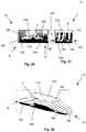
- the devicecan be uni-axially compressed or squeezed from a first configuration, such as a radially compacted configuration (e.g., as shown in Figure 1 ), into a second configuration, such as a radially expanded configuration (e.g., as shown in Figure 3 ).
- the uni-axial compressioncan be parallel to the longitudinal axis (in this application, longitudinal axis by itself refers to the longitudinal axis of the expandable support device as a whole).
- the expandable support devicecan get longitudinally shorter as the device radially expands.
- expandable support deviceand stent are used interchangeably and non-limitingly throughout the remainder of the specification.
- a stentis type of the expandable support device.
- the stentcan transform the compressive force (i.e., from longitudinally applied work: longitudinally applied compressive force multiplied by a longitudinal distance that the stent is compressed) into a radial force (i.e., from the radially delivered work: radial expansion force multiplied by a radial distance that the stent is expanded).
- This force transformationcan "gear up" the radial force from the longitudinal force.
- the stentcan produce radial forces during expansion that can be from about 1 to about 50 times, yet more narrowly from about 10 times to about 30 times, the applied longitudinal compressive force.
- the expandable support devicecan be configured to radially expand nonuniformly, uniformly in all angles from the longitudinal axis, along the length of the longitudinal axis, or combinations thereof.
- the expandable support devicecan be configured to expand in multiple planes (i.e., multipanar expansion), in a single plane (i.e., uniplanar expansion), or combinations thereof. For example, during uniplanar expansion, the expandable support device can expand only taller (i.e., in a vertical plane), only wider (i.e., in a horizontal plane), or only in a plane not horizontal or vertical.
- the expandable support devicecan have non-uniform radial expansion, for example the device can expand from a pre-deployed circular diameter of about 3 mm (0.1 in.) to a deployed rectangular configuration that can measure about 4 mm (0.1 in.) by about 6 mm (0.2 in.).
- the expandable support devicecan have radially contracted configurations with non-round cross sections, for example, square, triangular, rectangular, or combinations thereof.
- the expandable support devicecan have a tapered radially contracted and/or radially expanded configuration.
- the expandable support devicecan have open or closed ends that can allow or prevent fluid flow.
- the porosity around the expandable support devicecan vary radially, angularly, and/or longitudinally (e.g., low to high, or even low in one section and high in other sections).
- the expandable support devicecan be deployed to a treatment site fully or partly radially contracted or fully or partially radially expanded configuration.
- the expandable support devicecan have a very high shear strength.
- the expandable support devicecan be locked open by controlling the expandable support device length once the expandable support device is radially expanded. Locking or controlling the longitudinal length of the expandable support device length once the device is expanded can, for example, increase the maximum radial and shear forces sustainable by the expandable support device.
- the expandable support devicecan be balloon expandable (e.g., deformable) or not balloon expandable or self-expandable (e.g., resilient).
- the stentcan be delivered using a uni-axial delivery/expansion system, such as those disclosed herein and in the references mentioned herein.
- the delivery systemi.e., deployment tool
- the deployment toolcan expand or contract.
- the deployment toolcan have a sliding sheath shaft.
- the deployment toolcan deploy the expandable support device uniformly from both longitudinal ends. Longitudinal compaction of the expandable support device can radially expand the expandable support device.
- the expandable support devicecan be partially or completely radially expanded by rotating one end of the expandable support device relative to the other end of the expandable support device.
- the expandable support devicecan have a small cross-sectional profile [0028]
- the expandable support devicecan have variable inner and/or outer diameters.
- the expandable support devicecan have a variable wall thickness (e.g., thick and thin spots radially, and/or angularly, and/or axially).
- the expandable support devicecan have variable cell dimensions, such as cell geometry (e.g., length, width, departure angle 72), gaps and offsets between cells, strut and/or link widths, uniformity of struts and cells, cells phase to one another.
- the first end of the expandable support devicecan have a different configuration that the second end of the expandable support device.
- the expandable support devicecan have a locking trellis.
- the expandable support devicecan be made from a ductile metal.
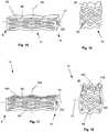
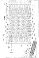
- Figure 1illustrates the expandable support device 14 in a contracted configuration.
- the expandable support device 14can have a device first end 8 and a device second end 10.
- the device first end 8 and the device second end 10can be at opposite longitudinal ends of the expandable support device 14.
- the expandable support device 14can have an expandable support device wall 16.
- the expandable support device 14can be configured as a cylinder.
- the expandable support device 14can have one or more cells.
- the cellscan be holes or voids in the expandable support device wall 16.
- the cellscan be aligned in cell rows 4, cell columns 184, staggered, or randomly configured on the expandable support device 14.
- a uni-axial compressive forceshown by arrows, can be applied on the device first end 8 and the device second end 10.
- the compressive forcecan produce a radial expansion 18, shown by arrows.
- Figure 2illustrates a single exemplary cell from the expandable support device 14.
- the cellcan be formed by links 20 connected at joints 22 (e.g., hinges 24).
- the links 20can be constrained, for example, to have no degrees of freedom within each link 20.
- the links 20can be rigid and/or flexible.
- the joints 22can be separate and discrete elements from the links 20, and/or sections of the expandable support device wall 16 that are designed to flex or bend when the compression force is applied.
- the cellcan be a four-bar linkage. The cell can be in the closed configuration, as shown, before the compression force is applied.
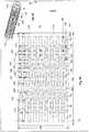
- Figure 3illustrates the expandable support device 14 of Figure 1 in an expanded configuration.
- Figure 4illustrates the cell of Figure 3 after radial expansion 18, as shown by arrows.
- the cellcan be in an open configuration after radial expansion 18.
- the expandable support device 14 and/or cellscan expand radially and contract longitudinally.
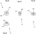
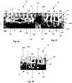
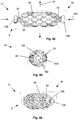
- FIGs 5a and 5billustrate that the cells 2, such as a first cell 34, a second cell 36 (shown in Figure 5a ), and other cells (not shown), can have two, three, four, or more hinges 24.
- the hinges 24can have one or more degrees of rotational and/or translational freedom.
- the hinges 24can have one or more hinge points 44.
- the device wall 26can plastically deform and/or resiliently deform at the hinge points 44. The compression force applied along the longitudinal axis can cause the rotation at the hinge points 44.
- the hinge points 44can have one, two, three, four, five, six or more degrees of rotational freedom.
- the hinge points 44can have translational and/or rotational degrees of freedom.
- the device wall 26can be made from any of the materials listed herein, for example a ductile metal or plastic, such as a polymer.
- the cellscan rotate (i.e., flex and bend) similarly to a trellis or four-bar linkage, as shown supra.
- the cellcan have a cell length 28.
- the cell length 28can be measured along the longitudinal axis of the expandable support device 14 and/or the cell longitudinal axis 30.
- the cell length 28can be from about 0.1 mm (0.005 in.) to about 10 mm (0.5 in.), more narrowly from about 1.9 mm (0.075 in.) to about 8 mm (0.3 in.), for example about 5 mm (0.2 in.).
- the cellcan have a branch length 32, for example from about 0.1 times the cell length 28 to about 0.9 times the cell length 28, more narrowly from about 0.25 times the cell length 28 to about 0.75 times the cell length 28, for example about 0.5 times the cell length 28 (i.e., the cell length 28 can be any cell length as disclosed herein).
- the transverse distance 40 along the expandable support device 14 between the first cell 34 and the second cellcan be a cello height gap.
- the cell height gap 38can be from about 0.1 mm (0.005 in.) to about 0.1 mm (0.1 in.), more narrowly from about 0.46 mm (0.018 in.) to about 1.5 mm (0.060 in.), for example about 0.76 mm (0.030 in.).
- the cellcan have a cell longitudinal axis 30. As shown, the first cell 34 can have a first cell longitudinal axis 66. The second cell can have a second cell longitudinal axis 68. The cell can have a first branch 48 and a second branch 50. Each branch can have a branch length 32. The branch length 32 can vary as the expandable support device 14 is deployed.
- Figure 5billustrates that the cell can have a first branch 48.
- the cellcan have a second branch 50.
- One or more branchescan terminate in a hinge 24, for example a five-point hinge 42.
- the five-point hinge 42can have five hinge points 44.
- the first branch 48can attach to the second branch 50 at two hinges 24, for example three-point hinges 46.
- the hinges 24can have hinge diameters 52. Examples for hinge diameters 52 within possible ranges of hinge diameters 52 are disclosed at least in Figure 49 .
- the angle between adjacent links 20can be a link angle 54.
- Examples for link angles 54 within possible ranges of link angles 54are disclosed at least in Figures 53 and 55 .
- the hinges 24can be configured to expand and/or contract the angle between the links 20 attached to the specific hinge 24.
- each hinge 24can have hinge point radius 56.
- the hinge point radius 56can be from about 0.1 mm (0.004 in.) to about 20 mm (0.8 in.), more narrowly from about 0.2 mm (0.008 in.) to about 4 mm (0.2 in.), for example about 1 mm (0.04 in.).
- Figure 6illustrates that the first cell 34 can have a first cell transverse axis 66.
- the second cellcan have a second cell transverse axis 60.
- the transverse axiscan intersect the center of area of the cell.
- the transverse axiscan intersect the hinge points 44 between the links 20 on the first and second branches 50.
- the distance between the first cell transverse axis 66 and the second cell transverse axis 60can be a cell row offset 64.
- the cell row offset 64can be zero, as shown in Figure 5 , or non-zero, as shown in Figure 6 .
- the cellcan have a hinge gap 62.
- the hinge gap 62can be the distance from one hinge 24 to the closest hinge 24 on the adjacent cell.
- Figure 7illustrates that one or more cells can have a departure angle 72.
- the departure angle 72can be the angle between the cell longitudinal axis and the longitudinal axis, or a longitudinal axis parallel 70.
- the departure angle 72can be positive and/or negative from about 0 degrees to about 90 degrees, more narrowly from about 5 degrees to about 45 degrees, yet more narrowly from about 7.5 degrees to about 30 degrees, for example about 15 degrees.
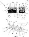
- Figure 8illustrates that the expandable support device 14, for example in a radially contracted configuration, can be loaded on a uni-axial deployment tool.
- the deployment toolcan have a slide 78.
- the deployment toolcan have a sheath or handle 74.
- the slide 78can be slidably attached to the handle 74.
- the slide 78 and the handle 74can have concurrent longitudinal axes (not explicitly shown).
- the slide 78can be rotationally attached to the handle 74 with respect to the concurrent longitudinal axes.
- the slide 78can be on the radial interior of the expandable support device 14.
- the slide 78can be fixedly or rotationally attached to a tool butt or head.
- the tool headcan releasably engage the device second end 10.
- the handle 74can releasably engage the device first end 8.
- Figure 9illustrates that a translational force, as shown by arrow 84, can be applied to the slide 78 in a direction away from the expandable support device 14 while an opposite force is applied to the handle 74 resulting in a translation, as shown by arrow 82, of the slide 78 with respect the handle 74.
- the translation showncan occur during deployment of the expandable support device 14.
- the tool head and the handle 74can longitudinally compress the expandable support device 14.
- the expandable support device 14can radially expand, as shown by arrows.
- the expandable support device 14can longitudinally shorten.
- Figure 10illustrates that when the expandable support device 14 is in the expanded configuration, the device first end 8 and/or the device second end 10 can have a radius equivalent to the radius of the device first end 8 and/or the device second end 10 in the contracted configuration.
- the remainder (i.e., other than the device first end 8 and/or the device second end 10) of the expandable support device 14can expand radially outward.
- the first and/or second device ends of the configuration of the expandable support device 14 shown in Figure 10can be constrained (i.e., attached) to the deployment tool, such as the deployment tool shown in Figures 8 and 9 , during deployment.
- Figure 11illustrates that the expandable support device 14 can have a locking bar 86.
- the locking bar 86can be fixedly or releasably attached to the first device end and/or the second device end before and/or during and/or after deployment of the expandable support device 14.
- the locking bar 86can be the length of the expandable support device 14 in the radially expanded configuration, as shown.
- the locking tension barcan increase radial and shear forces.
- the first device end and/or the second device endscan be completely and/or substantially closed.
- the closed device endscan create a hollow cavity in the device.
- the hollow cavity, with or without closed ends,can be filled with any material disclosed herein, for example, bone, bone chips, cement, bone morphogenic protein/powder (BMP), drugs, ceramics, small balls of any of the above, or combinations of the above.
- BMPbone morphogenic protein/powder
- Figures 12 through 14illustrate a method of deploying the expandable support device 14.
- the deployment toolcan transmit a rotation force to the expandable support device 14.
- the slide 78can be rotationally fixed to a fixator 90.
- the fixator 90can be a relatively rotationally stationary element of the deployment tool, or a relatively rotationally stationary separate element (e.g., a surgeon's hand or a wall).
- the deployment toolcan have a cam system to twist and/or allow twisting of the slide 78 with respect to the handle 74, for example from about 5 degrees to about 20 degrees.
- the deployment toolcan be hollow, for example allowing fluid to flow through the deployment tool.
- the slide 78 and/or handle 74can be hollow.
- the slide 78 and/or handle 74can have tool ports 88.
- the tool ports 88can allow flow into and through the deployment tool 76 (e.g., the handle 74 and/or slide 78).
- the device second end 10 and/or the slide cap 80can have a port in fluid communication with the hollow of deployment tool.
- the handle 74can be rotated, as shown by the arrow, with respect to the slide 78.
- the handle 74can be removably attached (e.g., rotationally or rotationally and translationaly fixed) to the expandable device at the device first end 8.
- the slide 78can be removably attached (e.g., rotationally or rotationally and translationaly fixed) to the expandable device at the device second end 10, for example at a slide cap 80.
- the handle 74can be translated, as shown by arrows 94, with respect to the slide 78 after and/or during rotation 92 of the handle 74 with respect to the slide 78 (e.g., rotation to unlock - for example with audible and/or tactile feedback such as a click - the handle 74 from the slide 78 and translation to compress the expandable support device 14, and/or partial rotation to enable easier translational longitudinal compression 162 and radial expansion 18 of the expandable support device 14 followed by the translational longitudinal compression 162 and radial expansion 18).
- Figure 14illustrates that the handle 74 can be further rotated and/or translated with respect to the slide 78 to fully expand the expandable support device 14.
- the expandable support device 14can expand similar to the untwisting of a coil spring. This "deployment twist" can be used to open the cells partially and/or completely. If the device is twisted slightly, the uni-axial compression method disclosed herein can then be used to complete deployment/expansion of the device.
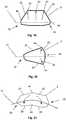
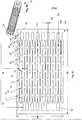
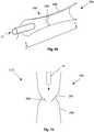
- Figure 15illustrates that the expandable support device 14 can have an expandable device transverse axis 100 at a right angle to the expandable device longitudinal axis 12.
- the expandable support device 14can have horizontal cells 96 on one side or two opposing sides of the expandable support device 14.
- the compression folds 98can be designed to encourage compression at the fold.
- the horizontal cells 96can be partially and/or fully diamond-shaped.
- Figure 15shows the expandable support device 14 in a radially compressed and longitudinally expanded configuration.
- the expandable support device 14can have an end cell 102 at the device first end 8 and/or the device second end 10.
- the end cells 102can be configured to engage the deployment tool (not shown).
- the end cells 102can be configured to engage the locking bar 86.
- the end cell 102 at the device first end 8can be a different geometry and size than the end cell 102 at the device second end 10.
- the expandable support device 14can have one or more compression folds 98.
- the expandable support device 14can have a round (e.g., circular, oval), tapered, triangular or square longitudinal cross-section.
- the expandable support device 14 with the square longitudinal cross-sectioncan be used the same as the expandable support device 14 with the round cross section.
- the expandable support device 14 with the square longitudinal cross-section when in a radially compressed configurationcan have a substantially square and/or round longitudinal cross-section when in a radially expanded configuration.
- the expandable support device 14 with the round longitudinal cross-section when in a radially compressed configurationcan have a substantially square and/or round longitudinal cross-section when in a radially expanded configuration.
- the expandable support device 14 with the square longitudinal cross-section when in a radially compressed configurationcan have a substantially different longitudinal cross-section when in a radially expanded configuration than the longitudinal cross-section in a radially expanded configuration of the expandable support device 14 with the round longitudinal cross-section when in a radially compressed configuration.
- Figure 16illustrates that expandable support device 14 of Figure 15 in a radially expanded and longitudinally compressed configuration.
- the expandable support device 14can be configured to have no cells on the top and/or bottom surface.
- Figure 17illustrates an expandable support device 14 similar to the expandable support device 14 of Figure 15 , but with vertical cells 104 in the top and/or bottom of the expandable support device 14.
- Figure 18illustrates the expandable support device 14 of Figure 17 in a radially expanded and longitudinally compressed configuration.
- the vertical cells 104 and/or the horizontal cells 96can be closed and/or open in the radially expanded configuration.
- Shape and density changes of the expandable support device 14 during radial expansion 18can be altered by different designs of the cell geometry.
- Figure 19illustrates the cell in a radially expanded configuration.
- the cellcan be configured to expand in a single plane, as shown by arrows.
- the cellcan be configured to expand in a single or substantially singular direction (e.g., translating and not rotating one or more links 20), as shown by arrows.
- the hinge points 44 and links 20can be configured as shown to allow for uniplanar expansion.
- the expandable device longitudinal axes shown in Figures 19 through 21can be of configurations after the expandable support devices 14 are radially expanded.
- Figure 20illustrates the cell in a radially expanded configuration.
- the cellcan be configured to allow expansion in a tapered configuration, as shown by arrows.
- Expansion in a tapered expansioncan include translational expansion of two opposite hinge points 44 near the same longitudinal or transverse end of the cell.
- Figure 21illustrates the cell in a radially expanded configuration.
- the cellcan be configured to allow expansion in a curved configuration, as shown by arrows.
- Expansion in a curved expansioncan include rotation in the same direction by two or more substantially or completely opposite hinge points 44 on opposite sides of the cell.
- Figures 22 through 25illustrates that the expandable support device 14 can have a radially contracted configuration with a substantially circular cross-section A-A.
- the expandable support device 14can be configured, for example due to cell configuration, to radially expand to a cross-section B-B that can be circular, as shown in Figure 22 .
- the expandable support device 14can be configured, for example due to cell configuration, to radially expand to a cross-section B-B that can be oval having a major axis in a first direction, as shown in Figure 23 .
- the expandable support device 14can be configured, for example due to cell configuration, to radially expand to a cross-section B-B that can be oval having a major axis in a second direction (e.g., at a right angle to the first direction), as shown in Figure 24 .
- the expandable support device 14can be configured, for example due to cell configuration, to radially expand to a cross-section B-B that can be substantially or completely triangular (e.g., with and/or without rounded corners), as shown in Figure 25 .
- the expandable support device 14 with a circular cross-section A-A in a radially non-expanded configurationcan radially expand to a non-circular cross-section B-B, for example, due to varying cell geometries (e.g., radial and/or angular/transverse and/or longitudinal variations of each cell and/or from cell to cell).
- the radially-expanded cross-section B-Bcan be centered or not centered on the radially non-expanded cross-section A-A, for example, due to varying cell geometries (e.g., radial and/or angular/transverse and/or longitudinal variations of each cell and/or from cell to cell).
- Figures 26 and 27illustrate the expandable support device 14 in a radially contracted configuration and a radially expanded configuration, respectively.
- the expandable support device 14can be compressed along the expandable device longitudinal axis 12 to radially expand.
- the links 20can rotate at the hinge points 44 during radial expansion 18 and contraction.
- the expandable support device 14has a first end ring 106 at the device first end 8.
- the expandable support device 14can have a second end ring 108 at a device second end 10.
- One or both end rings 174can engage the deployment tool (not shown) during deployment including longitudinal compression 162.
- the expandable support device 14can have side links 20 extending from the end rings 174, for example each at a fixed (as shown) or hinge point 44.
- Cross links 110can extend from the side links 114, for example each at a fixed or hinge (as shown) point 44.
- Top 112 and bottom links 116can extend from the cross links 110, for example each at a hinge (as shown) point 44.
- the top, bottom and side links 114can be substantially parallel to the expandable device longitudinal axis 12.
- the cross links 110can be substantially not parallel to the expandable device longitudinal axis 12.
- One having ordinary skill in the artunderstands that the orientation of the expandable support device 14 can turn side links 114 into top 112 or bottom links 116 and vice versa, as well as top links 112 into bottom links 116 and vice versa.
- the bottom 116 and top 112 linkscan terminate in first end proximal tips 120 and second end proximal tips 122.
- Each side of the expendable support devicecan have one, two or more side links 114, for example in (as shown) and/or out of line with each other and overlapping and/or not overlapping (as shown).
- Figure 27illustrates the longitudinal compressive force 6, shown by arrows, that can be applied to the end rings 174, for example to radially expand the expandable support device 14.
- a longitudinal tensile forcecan be applied at the end rings 174, for example, to radially contract the expandable support device 14.
- the longitudinal forcescan be applied aligned with the longitudinal axis (i.e., the center as seen in cross-section A-A or B-B) of the expandable support device 14.
- Figure 28illustrates that the expandable support device 14 can have one, two or more second end distal tips 126 and/or second end proximal tips 122 at the second end. Either device end can have no end ring 174. The distal and/or proximal tips 118 can engage the deployment tool (not shown) during deployment including longitudinal compression 162.
- the expandable support device 14can have a seam 128.
- the seam 128can partially or completely internally separate individual links 20 and/or the end rings 174.
- the seam 128can completely internally separate the first end ring 106 and the top link 112, as shown.
- the top link 112 and/or the first end ring 106can slide 78 against itself at the seam 128, for example, encouraging radially expansion in the direction of the seam 128 during longitudinal compression 162.
- Figures 29 and 30illustrate that the expandable support device 14 can have a top link, cross links 110, and one, two (as shown), or more bottom links 116.
- a first bottom link 132 and a second bottom link 134can be in (as shown) and/or out of line with each other and overlapping and/or not overlapping (as shown).
- the expandable support device 14can have no end rings 174.
- the first bottom link 132can have a first end distal tip 130.
- the top link 112can have a first end proximal tip 120.
- the second bottom link 134can have a second end distal tip 126.
- the top link 112can have a second end proximal tip 122.
- Figure 31illustrates that the longitudinally compressive force 6, as shown by arrows, can be applied at the first end distal tip 130 and second end distal tip 126, for example to cause radial expansion 18 of the expandable support device 14.
- the longitudinal tensile forcecan be applied at the first end distal tip 130 and the second end distal tip 126, for example, to radially contract the expandable support device 14.
- the longitudinal forcescan be applied unaligned with the longitudinal axis of the expandable support device 14.
- Figures 32 and 33illustrates that the top link 112 and/or the bottom link 116 can be flat.
- the cross links 110can extend from the top link 112 and/or bottom link 116 at an about 90° angle from the outer surface of the top link 112 and/or bottom link 116.
- Figures 34 and 35illustrate that the longitudinally compressive force 6, as shown by arrows, can be applied at the first end distal tip 130 and second end distal tip 126, for example to cause radial expansion 18 of the expandable support device 14.
- a longitudinal tensile forcecan be applied at the first end distal tip 130 and the second end distal tip 126, for example, to radially contract the expandable support device 14.
- the longitudinal forcescan be applied on substantially diametrically opposite corners of the expandable support device 14.
- the expandable support device 14can have a in a radially contracted and/or radially expanded configuration can have a square or rectangular cross-section A-A and/or B-B.
- the expandable support device 14can have a radially contracted height 136 and a radially expanded height 138.
- the radially contracted height 136can be from about 2 mm (0.08 in.) to about 50 mm (2.0 in.), more narrowly from about 5 mm (0.2 in.) to about 20 mm (0.79 in.), yet more narrowly from about 6 mm (0.2 in.) to about 12 mm (0.47 in.), for example about 8.6 mm (0.33 in.), also for example about 8.0 mm (0.3 in.).
- the radially expanded height 138can be from about 3 mm (0.1 in.) to about 100 mm (3.94 in.), more narrowly from about 10 mm (0.39 in.) to about 40 mm (1.6 in.), yet more narrowly from about 12 mm (0.47 in.) to about 24 mm (0.94 in.), for example about 15.6 mm (0.614 in.), also for example about 16.0 mm (0.630 in.), also for example about 18.1 mm (0.712 in.).
- the expandable support device 14 in a radially expanded configurationcan withstand post-deployment vertical compressive forces 6 (i.e., coming from the top and bottom of the figures) of, for example about 2.02 kN (455 lbs.), also for example about 3.11 kN (700 lbs.), also for example about 4.00 kN (900 lbs.), also for example more than about 4.38 kN (985 lbs.) without collapse or other failure.
- the radially expanded height 138can reduce from the original radially expanded height 138 about 0.1% to about 20%, more narrowly from about 0.3% to about 15%, for example about 11%, also for example about 4.4%, also for example about 0.6%.
- Figure 36illustrates an expandable support device 14 similar to the embodiment shown in Figure 26 .
- Figure 37illustrates that the first end ring 106 can have a first engagement notch 142.
- the second end ring 108can have a second engagement notch 144.
- the engagement notches 158can be pre-formed and/or formed during use by the deployment tool 76.
- the engagement notches 158can be lined and/or coated with a hardened material.
- any combination or all of the tipse.g., first end proximal tips 120 and second end proximal tips 122 and/or the top and/or bottom and/or side links 114 can bend toward the expandable device longitudinal axis 12, for example so lines extending (as shown) from the tips would substantially intersect the expandable device longitudinal axis 12 at a taper angle 140.
- the taper angle 140can be from about 20° to about 70°, for example at about 45° (as shown).
- the expandable device longitudinal axis 12can bend during radial expansion 18.
- Figure 38illustrates that the longitudinal compression 162 force can be large enough to compress the end rings 174 toward the center of the expandable support device 14 past one or more tips.
- the first end ring 106can be compressed toward the center of the expandable support device 14 past one of the first end proximal tips 120, as shown.
- the tipscan have barbs, hooks, pins, anchors, or combinations thereof.
- Figures 39 and 40illustrate that one or more wires 148, filaments, fibers or combinations thereof can be threaded through adjacent or nearby cells.
- the expandable support device 14can have a first side link 146 and a first cross link 154 partially defining the first cell 34.
- the expandable support device 14can have a second side link 156 and/or a second cross link 150 partially defining a third cell 152.
- the first cell 34can be diametrically opposed to the third cell 152, for example, when the expandable support device 14 is in a radially expanded configuration.
- the wires 148can be wrapped between the first cell 34 and the third cell 152, as shown.
- the wires 148can be wrapped from about one to about 10 turns, for example two turns, as shown in Figures 39 and 40 .
- the wires 148can have a diameter, for example from about (0.003 in.) to about (0.100 in.), for example about (0.020 in.).
- the wire 148can be any material listed herein, for example a metal (e.g., stainless steel, Nitinol, Elgiloy), and/or a polymer (e.g., PTFE, PET, PE, PLLA).
- Figure 40illustrates that the expandable support device 14 can be radially compressed, for example the expanded height 138 can reduce from about 1% to about 10%, more narrowly from about 3% to about 8%, for example about 5%.
- the rulers 124 shown in Figures 26, 27 , 29, 31are numbered every 10 mm, and marked to the 1 mm on one side and 0.5 mm on the opposite side.
- the rulers 124 shown in Figures 32-40are numbered every 10 mm and every 1 in., and marked to the 1 mm and the 1/16 in.
- Figures 41 through 43illustrate the expandable support device 14 that can be in a radially contracted configuration.
- the expandable support device 14can have longitudinally elongated first cells 34, for example, at the device first end 8 and/or the device second end 10.
- the first cells 34can partially or completely have a smaller outer diameter 196 than the remainder of the expandable support device 14.
- the expandable support device 14can have one or more cell rows 4 of diamond-shaped second cells, for example, between one or two cell rows 4 of the first cells 34.
- the expandable support device 14can have one or more engagement notches 158 on the first 106 and/or second end rings 108.
- Figures 44 through 46illustrate that as the expandable support device 14 is longitudinally compressed, the expandable support device 14 can radially expand, as shown by arrows.
- the expandable support device 14 at the cell rows 4 of the first cells 34can radially contract, stay radially constant, or radially expand to a lesser degree than the second cell rows 4, during longitudinal compression 162 of the expandable support device 14.
- the first cells 34can be five-link or three-link cells.
- One or more links 20 in a cellcan be formed by the end ring 174.
- the second cellscan be four-link cells.
- the expandable support device 14can have a patent internal channel 160.
- the internal channel 160can extend from the device first end 8 to the device second end 10.
- the internal channel 160can allow fluid flow 296 through the expandable support device 14 when in a radially contracted and/or radially expanded configuration. When in a radially expanded and/or radially contracted configuration, fluid can flow through the cells.
- Figure 47illustrates that the expandable support device 14 can have first cells 34, second cells and third cells.
- the third cellscan radially protrude in part or whole from the remainder of the expandable support device 14.
- the configuration of the cellscan vary with respect to the expandable device longitudinal axis 12.
- Figure 48illustrates that the expandable support device 14 can have first 34, second 36, third 152, fourth 192 and fifth 194 cells.
- the first 34, second 36, third 152, fourth 192 and fifth 194 cellscan be in one or more first 164, second 166, third 168, fourth 170 and fifth 172 cell rows, respectively.
- the cell rows 4can overlap each other.
- the cells in a single cell row 4can progressively increase and/or decrease in one or more dimensions.
- the cells from one cell row 4 to the nextcan progressively increase and/or decrease in one or more dimensions.
- the cellscan be arranged in one or more, for example eight, cell columns 184.
- the cells in a single cell column 184can progressively increase and/or decrease in one or more dimensions.
- the cells from one cell column 184 to the next cell column 184can progressively increase and/or decrease in one or more dimensions.
- the number of cellscan vary from one cell column 184 to the next.
- Figure 49illustrates a flattened or unrolled wall of an expandable support device 14, or a cylindrical projection of the expandable support device 14.
- the expandable support device 14can have an outer circumference 196 and a device length 198.
- the outer circumference 196can be from about 24.9 mm (0.981 in.) to about 25.2 mm (0.992 in.), more narrowly from about 24.9 mm (0.981 in.) to about 25.1 mm (0.987 in.) or from about 25.0 mm (0.986 in.) to about 25.2 mm (0.992 in.), for example about 25.0 (0.984 in.) or for example about 25.1 mm (0.989 in.).
- the device length 198can be from about 27.1 mm (1.067 in.) to about 45.8 mm (1.803 in.), more narrowly from about 27.1 mm (1.067 in.) to about 27.3 mm (1.073 in.) or from about 30.4 mm (1.197 in.) to about 45.8 mm (1.803 in.), yet more narrowly from about 30.4 mm (1.197 in.) to about 30.6 mm (1.203 in.) or from about 45.6 mm (1.797 in.) to about 45.8 mm (1.803 in.), for example about 27.4 mm (1.080 in.) or about 30.5 mm (1.200 in.), or about 45.7 mm (1.800 in.).
- the expandable support device 14can have one or more of the cells.
- the cellscan be arranged orthogonally in cell columns 184 and cell rows 4.
- the first 164, second 166, third 168, fourth 170 and fifth 172 cell rowscan have the first 34, second 36, third 152, fourth 192 and fifth 194 cells, respectively.
- the cells in a first cell column 184can be aligned or unaligned (e.g., staggered) with the cells in an adjacent cell column 184.
- the cellscan be symmetric about a longitudinal center of the expandable support device 14.
- the cells in a single cell column 184can be separated by cell row gaps 176.
- the cell row gap 176can be about 1.01 mm (0.040 in.).
- the nearest distance between links 20 of cells in adjacent cell columns 184is a cell height gap 38.
- the cell height gap 38can be from about 0.559 mm (0.022 in.) to about 1.70 mm (0.067 in.), for example about 0.559 mm (0.022 in.) or about 1.1 mm (0.045 in.) or about 1.70 mm (0.067 in.).
- the first cell 34can have a first cell width 186.
- the second cellcan have a second cell width 188.
- the first cell width 186can be from about 3.81 mm (0.150 in.) to about 8.71 mm (0.343 in.), for example about 3.81 mm (0.150 in.) or about 7.62 mm (0.300 in.) or about 8.71 mm (0.343 in.).
- the second cell width 188can be from about 5.08 mm (0.200 in.) to about 8.71 mm (0.343 in.), for example about 5.08 mm (0.200 in.) or about 7.62 mm (0.300 in.) or about 8.71 mm (0.343 in.).
- the third 152, fourth 192 and fifth 194 cellscan have cell widths 226 equivalent to the first 186 and/or second cell widths 188.
- Each cellcan have two, three or more hinges 24.
- the hinges 24 on a single cellcan be connected to the other hinges 24 by links 20, as shown.
- the hinges 24can be radially enlarged portions of the cell.
- the hinges 24can be configured so that during longitudinal compression 162 of the expandable support device 14, the hinges 24 rotate to transfer the compressive energy to a radial energy, thereby radially expanding the expandable support device 14.
- the hinges 24can have hinge diameters 52 from about 0.51 mm (0.020 in.) to about 1.5 mm (0.059 in.), for example about 0.51 mm (0.020 in.) or about 1.0 mm (0.040 in.) or about 0.89 mm (0.035 in.) or about 0.76 mm (0.030 in.) or about 0.64 mm (0.025 in.) or about 0.51 mm (0.020 in.).
- the hinges 24can be a hinge gap 62 distance to the nearest hinge 24 on the adjacent cell column 184 cell.
- the hinge gaps 62can be from about 0.71 mm (0.028 in.) to about 1.1 mm (0.042 in.).
- the links 20can have link heights 182 (i.e., slot gaps).
- the link heights 182can be from about 0.25 mm (0.010 in.) to about 1.7 mm (0.067 in.), for example about 0.25 mm (0.010 in.) or about 1.7 mm (0.067 in.).
- the expandable support device 14can have a device length 198, a wall thickness 180 and an outer diameter 196.
- the device length 198can be from about 27.18 mm (1.070 in.) to about 45.72 mm (1.800 in.), for example about 27.18 mm (1.070 in.) or 30.48 mm (1.200 in) or about 45.72 mm (1.800 in.).
- the wall thickness 180can be from about 1.2 mm (0.049 in.) to about 1.7 mm (0.065 in.), for example about 1.2 mm (0.049 in.) or about 1.7 mm (0.065 in.).
- the outer diameter 196can be from about 6.35 mm (0.250 in.) to about 10.2 mm (0.400 in.), for example about 7.95 mm (0.313 in.) or about 7.98 mm (0.314 in.).
- the expandable support device 14can have end rings 174 at one or both longitudinal ends of the expandable support device 14.
- the end rings 174can have an end ring width 190.
- the end ring width 190can be about 1.8 mm (0.070 in.).
- the cells in the interior of the expandable support device 14can have larger and/or smaller cell widths 226, hinge gaps 62, hinge diameters 52, link heights 182, cell row gaps 176, than cells near the ends of the expandable support device 14. Any or all of the dimensions of the elements, configurations, features, and characteristics of the expandable support device 14 can be symmetric about the longitudinal center (i.e., center radial plane) of the expandable support device 14, as shown.
- Figure 50 and 51illustrate an embodiment of the expandable support device 14 similar to the expandable support device 14 shown in Figures 48 and 49 , but with different exemplary dimensions.
- Figures 52 and 53illustrate an expandable support device 14 that can have diamond-shaped (e.g., four-strut or four-link 20) cells.
- the expandable support device 14can have three-link (e.g., three-strut) or five-link (e.g., five-strut) cells, for example at the cell row 4 at each end of the expandable support device 14.
- the expandable support device 14can have, respectively from the longitudinal end to the longitudinal middle of the expandable support device 14, first struts 212, second struts 214, third struts 216 and fourth struts 218.
- the struts nearer the longitudinal middle of the expandable support devicecan have a greater or lesser strut thickness 210.
- Each strutcan have a variable or constant strut thickness over the length of the strut.
- the end of each strut near the longitudinal end of the expandable support device 14can be thicker or thinner than the end of the same strut nearer the longitudinal middle of the expandable support device 14.
- the first, second, third, fourth and fifth cells 34, 36, 152, 192 and 194can have first, second, third, fourth, and fifth cell angles 200, 202, 204, 206 and 208, respectively.
- the cell angle 234can be the longitudinal-facing angle on the cell.
- the cell angles 234can be from about 7.9° to about 21.27°, for example about 7.9° or about 8.0° or about 8.1 ° or about 9.9° or about 11.9° or about 15.9° or about 18.2° or about 21.27°.
- the struts 220can have strut thicknesses 210.
- the strut thicknesses 210can be from about 0.53 mm (0.021 in.) to about 0.91 mm (0.036 in.), for example 0.53 mm (0.021 in.) or about 0.76 mm (0.030 in.) or about 0.91 mm (0.036 in.).
- Figures 54 and 55illustrate an embodiment of the expandable support device 14 similar to the expandable support device 14 shown in Figures 52 and 53 , but with different exemplary dimensions.
- Figures 56 and 57illustrate that the expandable support device 14 can have end tabs 222.
- the end tabs 222can be blunt and/or sharpened.
- the expandable support device 14can have no end rings 174.
- the struts 220can have a constant strut thickness 210 along the expandable support device 14.
- the cellscan have uniform dimensions along the expandable support device 14, when the expandable support device 14 is in a radially contracted configuration.
- the cellscan have a cell corner radius 232 (e.g., about 0.08 mm (0.003 in.)).
- the struts 220can have strut lengths 236.
- the strut lengths 236can be equal to the cell width 226.
- the strut length 236can be about 3.78 mm (0.149 in.).
- the end tabs 222can have end tab widths 228 and end tab heights 230.
- the end tab width 228can be about 1.6 mm (0.064 in.).
- the end tab height 230can be about 1.4 mm (0.057 in.).
- the cellcan have a cell height 224.
- the cell height 224can be the link height 182.
- the cell height 224can be about 1.7 mm (0.067 in.).
- any or all elements of the expandable support device 14, deployment tool 76 and/or other devices or apparatuses described hereincan be made from, for example, a single or multiple stainless steel alloys (e.g., 304 SS, annealed), titanium alloys (e.g., titanium G2), nickel titanium alloys (e.g., Nitinol), cobalt-chrome alloys (e.g., ELGILOY® from Elgin Specialty Metals, Elgin, IL; CONICHROME® from Carpenter Metals Corp., Wyomissing, PA), nickel-cobalt alloys (e.g., MP35N® from Magellan Industrial Trading Company, Inc., Westport, CT), molybdenum alloys (e.g., molybdenum TZM alloy, for example as disclosed in International Pub.
- a single or multiple stainless steel alloyse.g., 304 SS, annealed
- titanium alloyse.g., titanium G2
- WO 03/082363 A2published 9 October 2003
- tungsten-rhenium alloysfor example, as disclosed in International Pub. No. WO 03/082363
- polymerssuch as polyethylene teraphathalate (PET), polyester (e.g., DACRON® from E. I.
- polypropylenepolypropylene
- aromatic polyesterssuch as liquid crystal polymers (e.g., Vectran, from Kuraray Co., Ltd., Tokyo, Japan), ultra high molecular weight polyethylene (i.e., extended chain, high-modulus or high-performance polyethylene) fiber and/or yarn (e.g., SPECTRA® Fiber and SPECTRA® Guard, from Honeywell International, Inc., Morris Township, NJ, or DYNEEMA® from Royal DSM N.V., Heerlen, the Netherlands), polytetrafluoroethylene (PTFE), expanded PTFE (ePTFE), polyether ketone (PEK), polyether ether ketone (PEEK), poly ether ketone ketone (PEKK) (also poly aryl ether ketone ketone), nylon, polyether-block co-polyamide polymers (e.g., PEBAX® from ATOFINA, Paris, France), aliphatic polyether polyurethanes (
- any or all elements of the expandable support device 14, deployment tool 76 and/or other devices or apparatuses described herein,can be, have, and/or be completely or partially coated with agents and/or a matrix a matrix for cell ingrowth or used with a fabric, for example a covering (not shown) that acts as a matrix for cell ingrowth.
- the matrix and/or fabriccan be, for example, polyester (e.g., DACRON® from E. I. Du Pont de Nemours and Company, Wilmington, DE), polypropylene, PTFE, ePTFE, nylon, extruded collagen, silicone or combinations thereof.
- the expandable support device 14, deployment tool 76 and/or elements of the expandable support device 14, deployment tool 76 and/or other devices or apparatuses described herein and/or the fabriccan be filled, coated, layered and/or otherwise made with and/or from cements, fillers, glues, and/or an agent delivery matrix known to one having ordinary skill in the art and/or a therapeutic and/or diagnostic agent. Any of these cements and/or fillers and/or glues can be osteogenic and osteoinductive growth factors.
- cements and/or fillersexamples include bone chips, demineralized bone matrix (DBM), calcium sulfate, coralline hydroxyapatite, biocoral, tricalcium phosphate, calcium phosphate, polymethyl methacrylate (PMMA), biodegradable ceramics, bioactive glasses, hyaluronic acid, lactoferrin, bone morphogenic proteins (BMPs) such as recombinant human bone morphogenetic proteins (rhBMPs), other materials described herein, or combinations thereof.
- DBMdemineralized bone matrix
- PMMApolymethyl methacrylate
- BMPsbone morphogenic proteins
- rhBMPsrecombinant human bone morphogenetic proteins
- the agents within these matricescan include any agent disclosed herein or combinations thereof, including radioactive materials; radiopaque materials; cytogenic agents; cytotoxic agents; cytostatic agents; thrombogenic agents, for example polyurethane, cellulose acetate polymer mixed with bismuth trioxide, and ethylene vinyl alcohol; lubricious, hydrophilic materials; phosphor cholene; anti-inflammatory agents, for example non-steroidal anti-inflammatories (NSAIDs) such as cyclooxygenase-1 (COX-1) inhibitors (e.g., acetylsalicylic acid, for example ASPIRIN® from Bayer AG, Leverkusen, Germany; ibuprofen, for example ADVIL® from Wyeth, Collegeville, PA; indomethacin; mefenamic acid), COX-2 inhibitors (e.g., VIOXX® from Merck & Co., Inc., Whitehouse Station, NJ; CELEBREX® from Pharmacia Corp
- the expandable support device 14can be any expandable support device 14 or combinations thereof or include elements thereof as described in PCT Application Numbers US2005/034,115, filed 21 September 2005 ; US2005/034,742, filed 26 September 2005 ; US2005/034,728 filed 26 September 2005 , US2005/037,126, filed 12 October 2005 ; and U.S.
- the expandable support devices 14can be hollow tubes before the cells are formed.
- the cellscan be cut or slotted (e.g., laser-slotted or laser-cut) from the hollow tubes.
- the tubescan be hollowed before and/or after the cells are formed.
- the expandable support devices 14can be made from individual filaments in a braided configuration.
- the devicecan be locked open by controlling the expanded braid's length.
- the devicecan be made from coiled springs.
- the coiled springscan be twisted into a small diameter, then untwisted or plastically twisted open to create radial force.
- the devicescan be made from any combination of the above methods.
- Figure 58illustrates that an expandable support device 14 can be deployed into a bone, such as a first vertebra 240.
- a deployment channel 238can be drilled or otherwise formed in the first vertebra 240.
- the deployment channel 238can provide access to a treatment site in the first vertebra 240.
- the deployment channel 238can be formed by the expandable support device 14 during deployment (e.g., ramming and crushing, screwing and displacing, ultrasound shaking and disintegrating, or otherwise transmitting energy through the expandable support device 14 to form the deployment channel 238).
- the expandable support device 14can be inserted along the insertion path 246 into the first vertebra 240, for example from the caudal and/or dorsal 252 side of the vertebra. (Ventral 250 and dorsal 252 directions and the spinal cord 248 are shown for orientation.)
- the expandable support device 14When the expandable support device 14 is in the first vertebra 240, the expandable support device 14 can be longitudinally compressed, as shown by arrows 162. The longitudinal compression can cause the cells to flex such that the expandable support device 14 can radially expand, as shown by arrows 18.
- Figure 59illustrates that the expandable support device 14 can be deployed into a treatment site in an intervertebral disc 244.
- the intervertebral disc 244can be partially or completely removed (e.g., by surgery or by a pathology) before the expandable support device 14 is inserted into the treatment site.
- the expandable support device 14can be inserted along the insertion path 246, for example from a directly dorsal 252 location.
- the expandable support device 14When the expandable support device 14 is in the first vertebra 240, the expandable support device 14 can be longitudinally compressed, as shown by arrows 162. The longitudinal compression can cause the cells to flex such that the expandable support device 14 can radially expand, as shown by arrows 18. In a radially expanded configuration, the expandable support device 14 can be in contact with the first vertebra 240 and a second vertebra 242.
- Figure 60illustrates that a single expandable support device 14 can be deployed at an angle with respect to the center sagittal plane.
- Figure 61illustrates that a first expandable support device 256 can be deployed in a symmetrically offset (i.e., at the negative distance and angles) configuration with respect to the center sagittal plane compared to a second expandable support device 258.
- Figure 62illustrates that the first and second expandable support devices 258 can be deployed on one side of the center sagittal plane symmetrically offset with respect to the center sagittal plane compared to the third and fourth expandable support devices 262.
- the first expandable support device 256can be deployed parallel and adjacent (e.g., in contact and/or attached) to the second expandable support device 258.
- the third expandable support device 260can be deployed parallel and adjacent (e.g., in contact and/or attached) to the fourth expandable support device 262.
- Figure 63illustrates that the first expandable support device 256 can be deployed on one side of the center sagittal plane symmetrically offset with respect to the center sagittal plane compared to the fourth expandable support device 262.
- the second expandable support device 258can be deployed on one side of the center sagittal plane symmetrically offset with respect to the center sagittal plane compared to the third expandable support device 260.
- the first 256 and fourth 262 expandable support devicescan be offset from the center dorsal 252 plane at the negative distance that the second 258 and third 260 expandable support devices are offset from the center dorsal 252 plane.
- Figure 64illustrates that the expandable support device 14 can be deployed in a curved or otherwise angled configuration.
- FIG. 60 through 64The configurations illustrated in Figures 60 through 64 can be used for intervertebral and/or intravertebral deployment of the expandable support device 14.
- the deployed position of the expandable support device 14is shown over the transverse (i.e., horizontal) cross-section of the vertebra 254.
- the expandable support device 14can be partially or completely filled with any of the materials disclosed herein, including BMPs, morselized bone, DBM, and combinations thereof.
- Figure 65illustrates that the expandable support device 14 can be loaded onto a deployment tool 76 and positioned, as shown by arrow, into a lumen 276 at or adjacent to a treatment site.
- the lumen 276can be a venous or arterial blood vessel (e.g., coronary or peripheral).
- the lumen 276can have a damaged lumen wall 274 at the treatment site, for example as a symptom of atherosclerosis (e.g., stenosis).
- the first deployment arm 264can have a first catch 270.
- the second deployment arm 266can have a second catch 272.
- the first catch 270can be removably attached to the first end of the expandable support device 14.
- the second catch 272can be removably attached to the second end of the expandable support device 14.
- Figure 66illustrates that a first translating force 278, as shown by arrow, can be applied to the first deployment arm 264 and that a substantially equal and opposite second translating force 280, as shown by arrow, can be applied to the second deployment arm 266.
- the translating forcescan be transmitted to longitudinally compress the expandable support device 14.
- the expandable support device 14can radially expand, as shown by arrows.
- the expanded expandable support device 14can treat damaged the treatment site, for example by reconfiguring the lumen wall 268.
- the first 270 and second catches 272can be removed from the expandable support device 14.
- the deployment tool 76can be removed from the treatment site.
- Figure 67illustrates that the treatment site can be an aneurysm 282.
- the aneurysm 282can be thoracic, abdominal, cerebral, coronary, or other vascular aneurysms.
- the aneurysm 282can be fusiform, saccular, a pseudoaneurysm, or combinations thereof.
- Figure 68illustrates that the expandable support device 14 can be radially expanded as shown in Figure 66 .
- the expandable support device 14can cover the aneurysm neck, for example minimizing and/or preventing fluid flow 296 into and/or out of the aneurysm 282.
- the expandable support device 14can have a coating and/or a graft minimizing and/or preventing fluid flow 296 through the wall of the expandable support device 14.
- One or more expandable support devices 14 with or without graftscan be deployed into the aneurysm 282, for example before the expandable support device 14 is deployed as shown in Figure 68 .
- the expandable support devices 14can be radially expanded or not radially expanded.
- Figures 69 and 70illustrate that the expandable support device 14 can positioned, as shown by arrow, at or adjacent to a valve 290.
- the valve 290can have a valvular lumen wall 288.
- the valve 290can have an annulus 284 and/or leaflets 286.
- the valve 290can be a heart valve, for example a stenotic mitral or aortic valve.
- the expandable support device 14can be positioned to longitudinally overlap the annulus 284 and/or leaflets 286.
- the expandable support device 14can then be longitudinally compressed, for example causing radial expansion 18.
- the expandable support device 14can have attachment devices, such as attachment tabs 292 and/or an expandable rim 294, for attaching new leaflets 286.
- the expandable rim 294can circumferentially lock during deployment.
- the expandable support device 14can be longitudinally compressed, for example causing radial expansion 18 of the expandable support device 14.
- the cells of the expandable support device 14can be configured to taper the middle of the expandable support device 14 during radial expansion 18, such as shown in Figures 71, 72 and 73 .
- the cells at or near the ends of the expandable support device 14can be configured to radially expand more than the cells at or near the middle of the expandable support device 14.
- the expandable support device 14can be deformable and a balloon as shown in Figures 9 or 10 of PCT Application Number US2005/033,965, filed 21 September 2005 ; and U.S.
- Provisional Patent Application Numbers 60/611,972, filed 21 September 2004 published as WO 2006/034396can be used to radially expand the expandable support device 14.
- the first end and/or second end of the expandable support device 14can be completely or substantially open, as shown in Figures 71 and 72 , for example, allowing flow through the valve 290 during deployment of the expandable support device 14.
- the first end and/or second end of the expandable support device 14can have cells, as shown in Figure 73 , for example, allowing flow through the valve 290, as shown by arrows, during deployment of the expandable support device 14.
- Figure 74illustrates that the expandable support device 14 can be radially contracted (e.g., by applying a longitudinal tensile force, and/or a radial tensile force, and/or removing the compressive forces 6 on a radially self-contracting expandable support device 14).
- the expandable support device 14can be withdrawn from the valve 290, as shown by arrow.
- the expandable support device 14can be left in the valve 290 permanently or semi-permanently. New leaflets 286 can be attached to the expandable support device 14, for example at the attachment tabs 292 and/or expandable rim 294.
- Figures 69, 70 , 71, 72 and 74do not show the deployment tool 76 for clarity of illustration.
- the expandable support device 14can be used for tissue distraction.
- One or more expandable support devices 14can be used on one application (i.e., patient).
- the deployment tools 76 used hereincan, for example, be the deployment tools 76 disclosed herein, the deployment tool 76 (i.e., including balloons) disclosed in U.S. Provisional Patent Application Nos. 60/611,972 filed 21 September 2004 published as WO 2006/034396 , 60/612,724 filed 24 September 2004 published as US 2007/219634 , and 60/617,810 filed 12 October 2004 published as US 2007/219634 .
Landscapes
- Health & Medical Sciences (AREA)
- Engineering & Computer Science (AREA)
- Biomedical Technology (AREA)
- Orthopedic Medicine & Surgery (AREA)
- Life Sciences & Earth Sciences (AREA)
- Public Health (AREA)
- Transplantation (AREA)
- Heart & Thoracic Surgery (AREA)
- Veterinary Medicine (AREA)
- General Health & Medical Sciences (AREA)
- Animal Behavior & Ethology (AREA)
- Cardiology (AREA)
- Vascular Medicine (AREA)
- Oral & Maxillofacial Surgery (AREA)
- Neurology (AREA)
- Optics & Photonics (AREA)
- Physics & Mathematics (AREA)
- Surgery (AREA)
- Medical Informatics (AREA)
- Nuclear Medicine, Radiotherapy & Molecular Imaging (AREA)
- Molecular Biology (AREA)
- Physical Education & Sports Medicine (AREA)
- Prostheses (AREA)
- Materials For Medical Uses (AREA)
Description
- This invention relates to expandable support devices for biological implantation and methods of using the same. More specifically, the expandable support devices can be used to treat vertebral, vascular, and valvular disorders.
- This invention relates to devices for providing support for biological tissue, for example to repair spinal compression fractures, and methods of using the same.
- Vertebroplasty is an image-guided, minimally invasive, nonsurgical therapy used to strengthen a broken vertebra that has been weakened by disease, such as osteoporosis or cancer. Vertebroplasty is often used to treat compression fractures, such as those caused by osteoporosis, cancer, or stress.
- Vertebroplasty is often performed on patients too elderly or frail to tolerate open spinal surgery, or with bones too weak for surgical spinal repair. Patients with vertebral damage due to a malignant tumor may sometimes benefit from vertebroplasty. The procedure can also be used in younger patients whose osteoporosis is caused by long-term steroid treatment or a metabolic disorder.
- Vertebroplasty can increase the patient's functional abilities, allow a return to the previous level of activity, and prevent further vertebral collapse. Vertebroplasty attempts to also alleviate the pain caused by a compression fracture.
- Vertebroplasty is often accomplished by injecting an orthopedic cement mixture through a needle into the fractured bone. The cement mixture can leak from the bone, potentially entering a dangerous location such as the spinal canal. The cement mixture, which is naturally viscous, is difficult to inject through small diameter needles, and thus many practitioners choose to "thin out" the cement mixture to improve cement injection, which ultimately exacerbates the leakage problems. The flow of the cement liquid also naturally follows the path of least resistance once it enters the bone - naturally along the cracks formed during the compression fracture. This further exacerbates the leakage.
- The mixture also fills or substantially fills the cavity of the compression fracture and is limited to certain chemical composition, thereby limiting the amount of otherwise beneficial compounds that can be added to the fracture zone to improve healing. Further, a balloon must first be inserted in the compression fracture and the vertebra must be expanded before the cement is injected into the newly formed space.
- A vertebroplasty device and method that eliminates or reduces the risks and complexity of the existing art is desired. A vertebroplasty device and method that is not based on injecting a liquid directly into the compression fracture zone is desired.
- Furthermore, completely or partially blocked blood vessels can be repaired by angioplasty and stenting. Angioplasty entails the reconstruction or recanalization of the vessel. A common method of angioplasty includes deploying a balloon to the blockage and inflating the balloon to push the blockage out of the lumen of the vessel. Often a stent is deployed when the balloon is inflated. The stent provides structural support and can deploy drugs locally to the blockage site. During inflation of the balloon, blood flow through the vessel is partially or completely interrupted.
- Aneurysms are often treated by deploying solid, liquid or gel agents to act as an embolism in the aneurysm. The liquids and gels can leak from the aneurysm during regular blood flow. The solids, often coils, are usually soft and undersized, so several coils must be deployed in a single aneurysm to fill the aneurysm. Further more, deploying solids into the weak-walled aneurysm increases the risk of rupturing the aneurysm. Also, certain configurations of aneurysms, such as those with large necks, or not discernable necks at all, are not good candidates for coil or other solid embolization since there is no natural neck to retain the implanted emboli.
- Valvular disorders, such as valvular stenosis, or other valvular insufficiencies can be treated by removing the existing leaflets in the valve and implanting an artificial valve. This procedure is usually performed as an "open" procedure, during which the patient undergoes severe trauma, such as a broken sternum and a large wound, that is extemporaneous to the replacement of the valve.
WO 00/44319 A1 WO 00/44321 A2 US 2004/111108 A1 discloses an angioplasty balloon including a non-deployable stent to prevent or reduce the potential for slippage of the inflated balloon with respect to the vessel wall being treated. The balloon includes a non-deployable stent that is adapted to be secured to the balloon or angioplasty balloon catheter. The stent has a proximal end, a distal end, and at least one extension section, at least one set of serpentine rings and at least one set of elongation links that allow expansion of the strut to accommodate the inflation of the balloon. The stent is made of a material so that the stent collapses upon deflation of the balloon.US 5 556 413 A discloses a stent, adapted to be inserted within a body lumen, and designed to expand and lock in an enlarged diameter form. The stent is designed so that the central portion of the stent body can be reversibly expanded at a selected site within a vessel lumen. Stent deployment can be accomplished by means of a two-stage process which allows the physician to abort the procedure if desired or if a complication develops. In the first stage, the body of the stent is expanded and then evaluated for such criteria as location relative to the stenosis and size relative to the vessel in which it resides. At this stage expansion is reversible and the decision to implant the stent can be aborted. The second stage expands and locks the ends of the stent in place so that the stent remains permanently implanted.SU 662 082 A1 WO 00/30523 A2 US 6 551 342 B1 discloses an intravascular filter device for use in capturing debris which may occur as a result of an intravascular procedure. The filter device comprises: an elongate member having a first end and a second end, the second end extending exterior of the vasculature; and a body including a first section defining a first end portion, a second section defining a mid-portion, a third section defining a second end portion, the first section, the second section and the third section form a conically tapering filter, the body includes an open first end and a substantially closed second end. The body has a longitudinal axis defined by a sidewall, the body being attached to the second end of the elongate member, and the elongate member extending from the open first end in a parallel relationship with the longitudinal axis. The mid-portion further comprises three ring members adjacently configured end to end, each ring member having a plurality of first members in an alternating V-pattern to form sixteen apices defining each a ring proximal end and a ring distal end.- According to the present invention there is provided the expandable support device of
claim 1. - Additional aspects of the invention are set out in the dependent claims.
- An expandable support device is disclosed herein. The expandable support device can be used to treat orthopedic (e.g., vertebral), vascular and/or valvular disorders. Examples include treating compression fractures in the spine, long bone fractures, spinal fusion, atherosclerosis, valvular stenosis, and aneurysms.
- The expandable support device can be configured to expand as a "reverse" stent: expanding radially when compressed longitudinally. The expandable support device can be deployed as a reverse stent between bones, in a bone, in a vessel, in an aneurysm across a valve, or combinations thereof
- The expandable support device can be a stent. The stent can be, for example, a reverse stent. The reverse stent can be configured to radially expand (e.g., open) as the stent is longitudinally compressed. The device can be uni-axially compressed or squeezed from a first configuration, such as a radially compacted configuration (e.g., as shown in
Figure 1 ), into a second configuration, such as a radially expanded configuration (e.g., as shown inFigure 3 ). The uni-axial compression can be parallel to the longitudinal axis (in this application, longitudinal axis by itself refers to the longitudinal axis of the expandable support device as a whole). The expandable support device can get longitudinally shorter as the device radially expands. - (The terms expandable support device and stent are used interchangeably and non-limitingly throughout the remainder of the specification. In the claims, a stent is type of the expandable support device.)
- The stent can transform the compressive force (i.e., from longitudinally applied work: longitudinally applied compressive force multiplied by a longitudinal distance that the stent is compressed) into a radial force (i.e., from the radially delivered work: radial expansion force multiplied by a radial distance that the stent is expanded). This force transformation can "gear up" the radial force from the longitudinal force. The stent can produce radial forces during expansion that can be from about 1 to about 50 times, yet more narrowly from about 10 times to about 30 times, the applied longitudinal compressive force.
- The expandable support device can be configured to radially expand nonuniformly, uniformly in all angles from the longitudinal axis, along the length of the longitudinal axis, or combinations thereof.
- The expandable support device can be configured to expand in multiple planes (i.e., multipanar expansion), in a single plane (i.e., uniplanar expansion), or combinations thereof. For example, during uniplanar expansion, the expandable support device can expand only taller (i.e., in a vertical plane), only wider (i.e., in a horizontal plane), or only in a plane not horizontal or vertical.
- The expandable support device can have non-uniform radial expansion, for example the device can expand from a pre-deployed circular diameter of about 3 mm (0.1 in.) to a deployed rectangular configuration that can measure about 4 mm (0.1 in.) by about 6 mm (0.2 in.). The expandable support device can have radially contracted configurations with non-round cross sections, for example, square, triangular, rectangular, or combinations thereof. The expandable support device can have a tapered radially contracted and/or radially expanded configuration. The expandable support device can have open or closed ends that can allow or prevent fluid flow.
- The porosity around the expandable support device can vary radially, angularly, and/or longitudinally (e.g., low to high, or even low in one section and high in other sections).
- The expandable support device can be deployed to a treatment site fully or partly radially contracted or fully or partially radially expanded configuration.
- The expandable support device can have a very high shear strength.
- The expandable support device can be locked open by controlling the expandable support device length once the expandable support device is radially expanded. Locking or controlling the longitudinal length of the expandable support device length once the device is expanded can, for example, increase the maximum radial and shear forces sustainable by the expandable support device.
- The expandable support device can be balloon expandable (e.g., deformable) or not balloon expandable or self-expandable (e.g., resilient).
- The stent can be delivered using a uni-axial delivery/expansion system, such as those disclosed herein and in the references mentioned herein. The delivery system (i.e., deployment tool) can expand or contract. The deployment tool can have a sliding sheath shaft. The deployment tool can deploy the expandable support device uniformly from both longitudinal ends. Longitudinal compaction of the expandable support device can radially expand the expandable support device.
- The expandable support device can be partially or completely radially expanded by rotating one end of the expandable support device relative to the other end of the expandable support device.
- The expandable support device can have a small cross-sectional profile [0028] The expandable support device can have variable inner and/or outer diameters. The expandable support device can have a variable wall thickness (e.g., thick and thin spots radially, and/or angularly, and/or axially). The expandable support device can have variable cell dimensions, such as cell geometry (e.g., length, width, departure angle 72), gaps and offsets between cells, strut and/or link widths, uniformity of struts and cells, cells phase to one another. The first end of the expandable support device can have a different configuration that the second end of the expandable support device.
- The expandable support device can have a locking trellis. The expandable support device can be made from a ductile metal.
- Embodiments of apparatus in accordance with the present invention will now be described, by way of example only, with reference to the accompanying drawings. Not all of the subject-matter illustrated in the drawings is covered by the independent claim. In particular,
Figs. 1-4 ,10 ,11 ,26-28 and36-55 show subject-matter that is covered by the independent claim. Figure 1 illustrates an embodiment of the expandable support device in a first configuration.Figure 2 illustrates a close up of a cell of the expandable support device ofFigure 1 .Figure 3 illustrates an embodiment of the expandable support device in a second configuration.Figure 4 illustrates a close up of a cell of the expandable support device ofFigure 3 .Figure 5a is a close up view of an example of a portion of the expandable support device including two cells.Figure 5b is a close up view of an example of a cell fromFigure 5 a.Figure 5c is a close up view of an example of a cell.Figures 6 and 7 are close up views of various examples of a portion of the expandable support device including two cells.Figures 8 and 9 illustrate an example of expanding the expandable support device with a deployment tool.Figures 10 and 11 illustrate various embodiments of the expandable support device in an expanded configuration.Figures 12 through 14 illustrate an example of expanding the expandable support device with a deployment tool.Figure 15 illustrates an example of the expandable support device in a contracted configuration.Figure 16 illustrates the expandable support device ofFigure 15 in an expanded configuration.Figure 17 illustrates an example of the expandable support device in a contracted configuration.Figure 18 illustrates the expandable support device ofFigure 17 in an expanded configuration.Figures 19 through 21 illustrate various examples of the cell.Figures 22 through 25 illustrate various examples of transverse cross- sections of the expandable support device in contracted (solid lines) and expanded (phantom lines) configurationsFigure 26 is a side view of an embodiment of the expandable support device in a contracted configuration.Figure 27 is a side view of the expandable support device ofFigure 26 in an expanded configuration.Figure 28 is a perspective view of an embodiment of the expandable support device.Figure 29 is a side view of an example of the expandable support device in a contracted configuration.Figure 30 is a perspective view of the expandable support device ofFigure 29. Figure 31 is a side view of the expandable support device ofFigure 29 in an expanded configuration.Figure 32 is a side view of an example of the expandable support device in a contracted configuration.Figure 33 is a front view of the expandable support device ofFigure 32 .Figure 34 is a side view of the expandable support device ofFigure 29 in an expanded configuration.Figure 35 is a front view of the expandable support device ofFigure 29 in an expanded configuration.Figure 36 is a side view of an embodiment of the expandable support device in a contracted configuration.Figures 37 and 38 are side views of various embodiments of the expandable support device in an expanded configuration.Figure 39 and 40 illustrate various embodiments of the expandable support device in an expanded configuration.Figure 41 is a side view of an embodiment of the expandable support device in a contracted configuration.Figure 42 is a front view of the expandable support device ofFigure 41 .Figure 43 is a perspective view of the expandable support device ofFigure 41 .Figure 44 is a side view of the expandable support device ofFigure 41 in an expanded configuration.Figure 45 is a front view of the expandable support device ofFigure 44 .Figure 46 is a perspective view of the expandable support device ofFigure 44 .Figure 47 illustrates an embodiment of the expandable support device.Figure 48 is a perspective view of an embodiment of the expandable support device.Figure 49 illustrates an embodiment of a flattened wall of the expandable support device ofFigure 48 .Figure 50 is a perspective view of an embodiment of the expandable support device.Figure 51 illustrates an embodiment of a flattened wall of the expandable support device ofFigure 50 .Figure 52 is a perspective view of an embodiment of the expandable support device.Figure 53 illustrates an embodiment of a flattened wall of the expandable support device ofFigure 52 .Figure 54 is a perspective view of an embodiment of the expandable support device.Figure 55 illustrates an embodiment of a flattened wall of the expandable support device ofFigure 54 .Figure 56 is a perspective view of an example of the expandable support device.Figure 57 illustrates an example of a flattened wall of the expandable support device ofFigure 56 .Figure 58 is a sagittal cross-sectional view of an example of a method for deploying the expandable support device in a vertebra.Figure 59 is a sagittal cross-sectional view of an example of a method for deploying the expandable support device in an intervertebral disc.Figures 60 through 64 are transverse (i.e., horizontal) cross-sectional views of examples of various methods for deploying various examples of the deployed expandable support device.Figures 65 and 66 illustrate an example of a method of using the expandable support device in the vasculature.Figures 67 and 68 illustrate an example of a method of using the expandable support device in the vasculature.Figure 69 is a perspective view of an example of a method of using the expandable support device across a valve, with the valve shown in cross-section.Figure 70 illustrates an example of cross-section C-C ofFigure 69 .Figure 71 is a perspective cross-section view of an example of a method of using the expandable support device across a valve.Figure 72 illustrates an example of cross-section D-D ofFigure 71 .Figure 73 illustrates an example of cross-section D-D ofFigure 71 .Figure 74 is a perspective view of an example of a method of using the expandable support device across a valve, with the valve shown in cross-section.Figure 1 illustrates theexpandable support device 14 in a contracted configuration. Theexpandable support device 14 can have a devicefirst end 8 and a devicesecond end 10. The devicefirst end 8 and the devicesecond end 10 can be at opposite longitudinal ends of theexpandable support device 14. Theexpandable support device 14 can have an expandablesupport device wall 16. Theexpandable support device 14 can be configured as a cylinder. Theexpandable support device 14 can have one or more cells. The cells can be holes or voids in the expandablesupport device wall 16. The cells can be aligned incell rows 4,cell columns 184, staggered, or randomly configured on theexpandable support device 14.- A uni-axial compressive force, shown by arrows, can be applied on the device
first end 8 and the devicesecond end 10. The compressive force can produce aradial expansion 18, shown by arrows. Figure 2 illustrates a single exemplary cell from theexpandable support device 14. The cell can be formed bylinks 20 connected at joints 22 (e.g., hinges 24). Thelinks 20 can be constrained, for example, to have no degrees of freedom within eachlink 20. Thelinks 20 can be rigid and/or flexible. Thejoints 22 can be separate and discrete elements from thelinks 20, and/or sections of the expandablesupport device wall 16 that are designed to flex or bend when the compression force is applied. The cell can be a four-bar linkage. The cell can be in the closed configuration, as shown, before the compression force is applied.Figure 3 illustrates theexpandable support device 14 ofFigure 1 in an expanded configuration.Figure 4 illustrates the cell ofFigure 3 afterradial expansion 18, as shown by arrows. The cell can be in an open configuration afterradial expansion 18. Theexpandable support device 14 and/or cells can expand radially and contract longitudinally.Figures 5a and5b illustrate that thecells 2, such as afirst cell 34, a second cell 36 (shown inFigure 5a ), and other cells (not shown), can have two, three, four, or more hinges 24. The hinges 24 can have one or more degrees of rotational and/or translational freedom. The hinges 24 can have one or more hinge points 44. Thedevice wall 26 can plastically deform and/or resiliently deform at the hinge points 44. The compression force applied along the longitudinal axis can cause the rotation at the hinge points 44. The hinge points 44 can have one, two, three, four, five, six or more degrees of rotational freedom. The hinge points 44 can have translational and/or rotational degrees of freedom. Thedevice wall 26 can be made from any of the materials listed herein, for example a ductile metal or plastic, such as a polymer. The cells can rotate (i.e., flex and bend) similarly to a trellis or four-bar linkage, as shown supra.- The cell can have a
cell length 28. Thecell length 28 can be measured along the longitudinal axis of theexpandable support device 14 and/or the celllongitudinal axis 30. Thecell length 28 can be from about 0.1 mm (0.005 in.) to about 10 mm (0.5 in.), more narrowly from about 1.9 mm (0.075 in.) to about 8 mm (0.3 in.), for example about 5 mm (0.2 in.). The cell can have abranch length 32, for example from about 0.1 times thecell length 28 to about 0.9 times thecell length 28, more narrowly from about 0.25 times thecell length 28 to about 0.75 times thecell length 28, for example about 0.5 times the cell length 28 (i.e., thecell length 28 can be any cell length as disclosed herein). Thetransverse distance 40 along theexpandable support device 14 between thefirst cell 34 and the second cell can be a cello height gap. Thecell height gap 38 can be from about 0.1 mm (0.005 in.) to about 0.1 mm (0.1 in.), more narrowly from about 0.46 mm (0.018 in.) to about 1.5 mm (0.060 in.), for example about 0.76 mm (0.030 in.). - The cell can have a cell
longitudinal axis 30. As shown, thefirst cell 34 can have a first celllongitudinal axis 66. The second cell can have a second celllongitudinal axis 68. The cell can have afirst branch 48 and asecond branch 50. Each branch can have abranch length 32. Thebranch length 32 can vary as theexpandable support device 14 is deployed. Figure 5b illustrates that the cell can have afirst branch 48. The cell can have asecond branch 50. One or more branches\can have two ormore links 20. One or more branches can terminate in ahinge 24, for example a five-point hinge 42. The five-point hinge 42 can have five hinge points 44. Thefirst branch 48 can attach to thesecond branch 50 at twohinges 24, for example three-point hinges 46. The hinges 24 can havehinge diameters 52. Examples forhinge diameters 52 within possible ranges ofhinge diameters 52 are disclosed at least inFigure 49 .- The angle between
adjacent links 20 can be alink angle 54. Examples for link angles 54 within possible ranges of link angles 54 are disclosed at least inFigures 53 and55 . The hinges 24 can be configured to expand and/or contract the angle between thelinks 20 attached to thespecific hinge 24. Figure 5c illustrates that each hinge 24 can havehinge point radius 56. Thehinge point radius 56 can be from about 0.1 mm (0.004 in.) to about 20 mm (0.8 in.), more narrowly from about 0.2 mm (0.008 in.) to about 4 mm (0.2 in.), for example about 1 mm (0.04 in.).Figure 6 illustrates that thefirst cell 34 can have a first celltransverse axis 66. The second cell can have a second celltransverse axis 60. The transverse axis can intersect the center of area of the cell. The transverse axis can intersect the hinge points 44 between thelinks 20 on the first andsecond branches 50. The distance between the first celltransverse axis 66 and the second celltransverse axis 60 can be a cell row offset 64. The cell row offset 64 can be zero, as shown inFigure 5 , or non-zero, as shown inFigure 6 . The cell can have ahinge gap 62. Thehinge gap 62 can be the distance from onehinge 24 to theclosest hinge 24 on the adjacent cell.Figure 7 illustrates that one or more cells can have adeparture angle 72. Thedeparture angle 72 can be the angle between the cell longitudinal axis and the longitudinal axis, or alongitudinal axis parallel 70. Thedeparture angle 72 can be positive and/or negative from about 0 degrees to about 90 degrees, more narrowly from about 5 degrees to about 45 degrees, yet more narrowly from about 7.5 degrees to about 30 degrees, for example about 15 degrees.Figure 8 illustrates that theexpandable support device 14, for example in a radially contracted configuration, can be loaded on a uni-axial deployment tool. The deployment tool can have aslide 78. The deployment tool can have a sheath or handle 74. Theslide 78 can be slidably attached to thehandle 74. Theslide 78 and thehandle 74 can have concurrent longitudinal axes (not explicitly shown). Theslide 78 can be rotationally attached to thehandle 74 with respect to the concurrent longitudinal axes. Theslide 78 can be on the radial interior of theexpandable support device 14. Theslide 78 can be fixedly or rotationally attached to a tool butt or head. The tool head can releasably engage the devicesecond end 10. Thehandle 74 can releasably engage the devicefirst end 8.Figure 9 illustrates that a translational force, as shown byarrow 84, can be applied to theslide 78 in a direction away from theexpandable support device 14 while an opposite force is applied to thehandle 74 resulting in a translation, as shown byarrow 82, of theslide 78 with respect thehandle 74. The translation shown can occur during deployment of theexpandable support device 14. The tool head and thehandle 74 can longitudinally compress theexpandable support device 14. Theexpandable support device 14 can radially expand, as shown by arrows. Theexpandable support device 14 can longitudinally shorten.Figure 10 illustrates that when theexpandable support device 14 is in the expanded configuration, the devicefirst end 8 and/or the devicesecond end 10 can have a radius equivalent to the radius of the devicefirst end 8 and/or the devicesecond end 10 in the contracted configuration. The remainder (i.e., other than the devicefirst end 8 and/or the device second end 10) of theexpandable support device 14 can expand radially outward. The first and/or second device ends of the configuration of theexpandable support device 14 shown inFigure 10 can be constrained (i.e., attached) to the deployment tool, such as the deployment tool shown inFigures 8 and 9 , during deployment.Figure 11 illustrates that theexpandable support device 14 can have a lockingbar 86. The lockingbar 86 can be fixedly or releasably attached to the first device end and/or the second device end before and/or during and/or after deployment of theexpandable support device 14. The lockingbar 86 can be the length of theexpandable support device 14 in the radially expanded configuration, as shown. The locking tension bar can increase radial and shear forces.- The first device end and/or the second device ends can be completely and/or substantially closed. The closed device ends can create a hollow cavity in the device. The hollow cavity, with or without closed ends, can be filled with any material disclosed herein, for example, bone, bone chips, cement, bone morphogenic protein/powder (BMP), drugs, ceramics, small balls of any of the above, or combinations of the above.
Figures 12 through 14 illustrate a method of deploying theexpandable support device 14. The deployment tool can transmit a rotation force to theexpandable support device 14. Theslide 78 can be rotationally fixed to afixator 90. Thefixator 90 can be a relatively rotationally stationary element of the deployment tool, or a relatively rotationally stationary separate element (e.g., a surgeon's hand or a wall). The deployment tool can have a cam system to twist and/or allow twisting of theslide 78 with respect to thehandle 74, for example from about 5 degrees to about 20 degrees.- The deployment tool can be hollow, for example allowing fluid to flow through the deployment tool. The
slide 78 and/or handle 74 can be hollow. Theslide 78 and/or handle 74 can havetool ports 88. Thetool ports 88 can allow flow into and through the deployment tool 76 (e.g., thehandle 74 and/or slide 78). The devicesecond end 10 and/or theslide cap 80 can have a port in fluid communication with the hollow of deployment tool. - As shown in
Figure 12 , thehandle 74 can be rotated, as shown by the arrow, with respect to theslide 78. Thehandle 74 can be removably attached (e.g., rotationally or rotationally and translationaly fixed) to the expandable device at the devicefirst end 8. Theslide 78 can be removably attached (e.g., rotationally or rotationally and translationaly fixed) to the expandable device at the devicesecond end 10, for example at aslide cap 80. - As shown in
Figure 13 , thehandle 74 can be translated, as shown byarrows 94, with respect to theslide 78 after and/or duringrotation 92 of thehandle 74 with respect to the slide 78 (e.g., rotation to unlock - for example with audible and/or tactile feedback such as a click - thehandle 74 from theslide 78 and translation to compress theexpandable support device 14, and/or partial rotation to enable easier translationallongitudinal compression 162 andradial expansion 18 of theexpandable support device 14 followed by the translationallongitudinal compression 162 and radial expansion 18). Figure 14 illustrates that thehandle 74 can be further rotated and/or translated with respect to theslide 78 to fully expand theexpandable support device 14. Theexpandable support device 14 can expand similar to the untwisting of a coil spring. This "deployment twist" can be used to open the cells partially and/or completely. If the device is twisted slightly, the uni-axial compression method disclosed herein can then be used to complete deployment/expansion of the device.Figure 15 illustrates that theexpandable support device 14 can have an expandable devicetransverse axis 100 at a right angle to the expandable devicelongitudinal axis 12. Theexpandable support device 14 can havehorizontal cells 96 on one side or two opposing sides of theexpandable support device 14. The compression folds 98 can be designed to encourage compression at the fold. Thehorizontal cells 96 can be partially and/or fully diamond-shaped.Figure 15 shows theexpandable support device 14 in a radially compressed and longitudinally expanded configuration.- The
expandable support device 14 can have anend cell 102 at the devicefirst end 8 and/or the devicesecond end 10. Theend cells 102 can be configured to engage the deployment tool (not shown). Theend cells 102 can be configured to engage the lockingbar 86. Theend cell 102 at the devicefirst end 8 can be a different geometry and size than theend cell 102 at the devicesecond end 10. Theexpandable support device 14 can have one or more compression folds 98. - The
expandable support device 14 can have a round (e.g., circular, oval), tapered, triangular or square longitudinal cross-section. Theexpandable support device 14 with the square longitudinal cross-section can be used the same as theexpandable support device 14 with the round cross section. Theexpandable support device 14 with the square longitudinal cross-section when in a radially compressed configuration can have a substantially square and/or round longitudinal cross-section when in a radially expanded configuration. Theexpandable support device 14 with the round longitudinal cross-section when in a radially compressed configuration can have a substantially square and/or round longitudinal cross-section when in a radially expanded configuration. Theexpandable support device 14 with the square longitudinal cross-section when in a radially compressed configuration can have a substantially different longitudinal cross-section when in a radially expanded configuration than the longitudinal cross-section in a radially expanded configuration of theexpandable support device 14 with the round longitudinal cross-section when in a radially compressed configuration. Figure 16 illustrates thatexpandable support device 14 ofFigure 15 in a radially expanded and longitudinally compressed configuration. Theexpandable support device 14 can be configured to have no cells on the top and/or bottom surface.Figure 17 illustrates anexpandable support device 14 similar to theexpandable support device 14 ofFigure 15 , but withvertical cells 104 in the top and/or bottom of theexpandable support device 14.Figure 18 illustrates theexpandable support device 14 ofFigure 17 in a radially expanded and longitudinally compressed configuration. Thevertical cells 104 and/or thehorizontal cells 96 can be closed and/or open in the radially expanded configuration.- Shape and density changes of the
expandable support device 14 duringradial expansion 18 can be altered by different designs of the cell geometry.Figure 19 illustrates the cell in a radially expanded configuration. The cell can be configured to expand in a single plane, as shown by arrows. The cell can be configured to expand in a single or substantially singular direction (e.g., translating and not rotating one or more links 20), as shown by arrows. The hinge points 44 andlinks 20 can be configured as shown to allow for uniplanar expansion. - The expandable device longitudinal axes shown in
Figures 19 through 21 can be of configurations after theexpandable support devices 14 are radially expanded. Figure 20 illustrates the cell in a radially expanded configuration. The cell can be configured to allow expansion in a tapered configuration, as shown by arrows. Expansion in a tapered expansion can include translational expansion of two opposite hinge points 44 near the same longitudinal or transverse end of the cell.Figure 21 illustrates the cell in a radially expanded configuration. The cell can be configured to allow expansion in a curved configuration, as shown by arrows. Expansion in a curved expansion can include rotation in the same direction by two or more substantially or completely opposite hinge points 44 on opposite sides of the cell.Figures 22 through 25 illustrates that theexpandable support device 14 can have a radially contracted configuration with a substantially circular cross-section A-A. Theexpandable support device 14 can be configured, for example due to cell configuration, to radially expand to a cross-section B-B that can be circular, as shown inFigure 22 . Theexpandable support device 14 can be configured, for example due to cell configuration, to radially expand to a cross-section B-B that can be oval having a major axis in a first direction, as shown inFigure 23 . Theexpandable support device 14 can be configured, for example due to cell configuration, to radially expand to a cross-section B-B that can be oval having a major axis in a second direction (e.g., at a right angle to the first direction), as shown inFigure 24 . Theexpandable support device 14 can be configured, for example due to cell configuration, to radially expand to a cross-section B-B that can be substantially or completely triangular (e.g., with and/or without rounded corners), as shown inFigure 25 .- The
expandable support device 14 with a circular cross-section A-A in a radially non-expanded configuration can radially expand to a non-circular cross-section B-B, for example, due to varying cell geometries (e.g., radial and/or angular/transverse and/or longitudinal variations of each cell and/or from cell to cell). The radially-expanded cross-section B-B can be centered or not centered on the radially non-expanded cross-section A-A, for example, due to varying cell geometries (e.g., radial and/or angular/transverse and/or longitudinal variations of each cell and/or from cell to cell). Figures 26 and 27 illustrate theexpandable support device 14 in a radially contracted configuration and a radially expanded configuration, respectively. Theexpandable support device 14 can be compressed along the expandable devicelongitudinal axis 12 to radially expand. Thelinks 20 can rotate at the hinge points 44 duringradial expansion 18 and contraction.- The
expandable support device 14 has afirst end ring 106 at the devicefirst end 8. Theexpandable support device 14 can have asecond end ring 108 at a devicesecond end 10. One or both end rings 174 can engage the deployment tool (not shown) during deployment includinglongitudinal compression 162. - The
expandable support device 14 can haveside links 20 extending from the end rings 174, for example each at a fixed (as shown) or hingepoint 44.Cross links 110 can extend from the side links 114, for example each at a fixed or hinge (as shown)point 44. Top 112 andbottom links 116 can extend from thecross links 110, for example each at a hinge (as shown)point 44. The top, bottom andside links 114 can be substantially parallel to the expandable devicelongitudinal axis 12. Thecross links 110 can be substantially not parallel to the expandable devicelongitudinal axis 12. One having ordinary skill in the art understands that the orientation of theexpandable support device 14 can turnside links 114 into top 112 orbottom links 116 and vice versa, as well astop links 112 intobottom links 116 and vice versa. - The bottom 116 and top 112 links can terminate in first end
proximal tips 120 and second endproximal tips 122. Each side of the expendable support device can have one, two ormore side links 114, for example in (as shown) and/or out of line with each other and overlapping and/or not overlapping (as shown). Figure 27 illustrates the longitudinalcompressive force 6, shown by arrows, that can be applied to the end rings 174, for example to radially expand theexpandable support device 14. A longitudinal tensile force can be applied at the end rings 174, for example, to radially contract theexpandable support device 14. The longitudinal forces can be applied aligned with the longitudinal axis (i.e., the center as seen in cross-section A-A or B-B) of theexpandable support device 14.Figure 28 illustrates that theexpandable support device 14 can have one, two or more second enddistal tips 126 and/or second endproximal tips 122 at the second end. Either device end can have noend ring 174. The distal and/orproximal tips 118 can engage the deployment tool (not shown) during deployment includinglongitudinal compression 162.- The
expandable support device 14 can have aseam 128. Theseam 128 can partially or completely internally separateindividual links 20 and/or the end rings 174. For example, theseam 128 can completely internally separate thefirst end ring 106 and thetop link 112, as shown. Thetop link 112 and/or thefirst end ring 106 can slide 78 against itself at theseam 128, for example, encouraging radially expansion in the direction of theseam 128 duringlongitudinal compression 162. Figures 29 and 30 illustrate that theexpandable support device 14 can have a top link,cross links 110, and one, two (as shown), or morebottom links 116. Afirst bottom link 132 and asecond bottom link 134 can be in (as shown) and/or out of line with each other and overlapping and/or not overlapping (as shown).- The
expandable support device 14 can have no end rings 174. Thefirst bottom link 132 can have a first enddistal tip 130. Thetop link 112 can have a first endproximal tip 120. Thesecond bottom link 134 can have a second enddistal tip 126. Thetop link 112 can have a second endproximal tip 122. Figure 31 illustrates that the longitudinallycompressive force 6, as shown by arrows, can be applied at the first enddistal tip 130 and second enddistal tip 126, for example to causeradial expansion 18 of theexpandable support device 14. The longitudinal tensile force can be applied at the first enddistal tip 130 and the second enddistal tip 126, for example, to radially contract theexpandable support device 14. The longitudinal forces can be applied unaligned with the longitudinal axis of theexpandable support device 14.Figures 32 and 33 illustrates that thetop link 112 and/or thebottom link 116 can be flat. Thecross links 110 can extend from thetop link 112 and/orbottom link 116 at an about 90° angle from the outer surface of thetop link 112 and/orbottom link 116.Figures 34 and 35 illustrate that the longitudinallycompressive force 6, as shown by arrows, can be applied at the first enddistal tip 130 and second enddistal tip 126, for example to causeradial expansion 18 of theexpandable support device 14. A longitudinal tensile force can be applied at the first enddistal tip 130 and the second enddistal tip 126, for example, to radially contract theexpandable support device 14. The longitudinal forces can be applied on substantially diametrically opposite corners of theexpandable support device 14.- The
expandable support device 14 can have a in a radially contracted and/or radially expanded configuration can have a square or rectangular cross-section A-A and/or B-B. Theexpandable support device 14 can have a radially contractedheight 136 and a radially expandedheight 138. The radially contractedheight 136 can be from about 2 mm (0.08 in.) to about 50 mm (2.0 in.), more narrowly from about 5 mm (0.2 in.) to about 20 mm (0.79 in.), yet more narrowly from about 6 mm (0.2 in.) to about 12 mm (0.47 in.), for example about 8.6 mm (0.33 in.), also for example about 8.0 mm (0.3 in.). The radially expandedheight 138 can be from about 3 mm (0.1 in.) to about 100 mm (3.94 in.), more narrowly from about 10 mm (0.39 in.) to about 40 mm (1.6 in.), yet more narrowly from about 12 mm (0.47 in.) to about 24 mm (0.94 in.), for example about 15.6 mm (0.614 in.), also for example about 16.0 mm (0.630 in.), also for example about 18.1 mm (0.712 in.). - As shown in
Figure 34 , theexpandable support device 14 in a radially expanded configuration can withstand post-deployment vertical compressive forces 6 (i.e., coming from the top and bottom of the figures) of, for example about 2.02 kN (455 lbs.), also for example about 3.11 kN (700 lbs.), also for example about 4.00 kN (900 lbs.), also for example more than about 4.38 kN (985 lbs.) without collapse or other failure. After radial compression loading, the radially expandedheight 138 can reduce from the original radially expandedheight 138 about 0.1% to about 20%, more narrowly from about 0.3% to about 15%, for example about 11%, also for example about 4.4%, also for example about 0.6%. Figure 36 illustrates anexpandable support device 14 similar to the embodiment shown inFigure 26 .Figure 37 illustrates that thefirst end ring 106 can have afirst engagement notch 142. Thesecond end ring 108 can have asecond engagement notch 144. Theengagement notches 158 can be pre-formed and/or formed during use by thedeployment tool 76. Theengagement notches 158 can be lined and/or coated with a hardened material.- Any combination or all of the tips (e.g., first end
proximal tips 120 and second end proximal tips 122) and/or the top and/or bottom and/orside links 114 can bend toward the expandable devicelongitudinal axis 12, for example so lines extending (as shown) from the tips would substantially intersect the expandable devicelongitudinal axis 12 at ataper angle 140. Thetaper angle 140 can be from about 20° to about 70°, for example at about 45° (as shown). The expandable devicelongitudinal axis 12 can bend duringradial expansion 18. Figure 38 illustrates that thelongitudinal compression 162 force can be large enough to compress the end rings 174 toward the center of theexpandable support device 14 past one or more tips. For example, thefirst end ring 106 can be compressed toward the center of theexpandable support device 14 past one of the first endproximal tips 120, as shown. The tips can have barbs, hooks, pins, anchors, or combinations thereof.Figures 39 and 40 illustrate that one ormore wires 148, filaments, fibers or combinations thereof can be threaded through adjacent or nearby cells. Theexpandable support device 14 can have afirst side link 146 and afirst cross link 154 partially defining thefirst cell 34. Theexpandable support device 14 can have asecond side link 156 and/or asecond cross link 150 partially defining athird cell 152. Thefirst cell 34 can be diametrically opposed to thethird cell 152, for example, when theexpandable support device 14 is in a radially expanded configuration. Thewires 148 can be wrapped between thefirst cell 34 and thethird cell 152, as shown. Thewires 148 can be wrapped from about one to about 10 turns, for example two turns, as shown inFigures 39 and 40 . Thewires 148 can have a diameter, for example from about (0.003 in.) to about (0.100 in.), for example about (0.020 in.). Thewire 148 can be any material listed herein, for example a metal (e.g., stainless steel, Nitinol, Elgiloy), and/or a polymer (e.g., PTFE, PET, PE, PLLA).Figure 40 illustrates that theexpandable support device 14 can be radially compressed, for example the expandedheight 138 can reduce from about 1% to about 10%, more narrowly from about 3% to about 8%, for example about 5%.- The
rulers 124 shown inFigures 26, 27 ,29, 31 , are numbered every 10 mm, and marked to the 1 mm on one side and 0.5 mm on the opposite side. Therulers 124 shown inFigures 32-40 are numbered every 10 mm and every 1 in., and marked to the 1 mm and the 1/16 in. Figures 41 through 43 illustrate theexpandable support device 14 that can be in a radially contracted configuration. In the radially contracted configuration, theexpandable support device 14 can have longitudinally elongatedfirst cells 34, for example, at the devicefirst end 8 and/or the devicesecond end 10. In the radially contracted configuration thefirst cells 34 can partially or completely have a smallerouter diameter 196 than the remainder of theexpandable support device 14. In the radially contracted configuration, theexpandable support device 14 can have one ormore cell rows 4 of diamond-shaped second cells, for example, between one or twocell rows 4 of thefirst cells 34. Theexpandable support device 14 can have one ormore engagement notches 158 on the first 106 and/or second end rings 108.Figures 44 through 46 illustrate that as theexpandable support device 14 is longitudinally compressed, theexpandable support device 14 can radially expand, as shown by arrows. Theexpandable support device 14 at thecell rows 4 of thefirst cells 34 can radially contract, stay radially constant, or radially expand to a lesser degree than thesecond cell rows 4, duringlongitudinal compression 162 of theexpandable support device 14. Thefirst cells 34 can be five-link or three-link cells. One ormore links 20 in a cell can be formed by theend ring 174. The second cells can be four-link cells.- The
expandable support device 14 can have a patentinternal channel 160. Theinternal channel 160 can extend from the devicefirst end 8 to the devicesecond end 10. Theinternal channel 160 can allowfluid flow 296 through theexpandable support device 14 when in a radially contracted and/or radially expanded configuration. When in a radially expanded and/or radially contracted configuration, fluid can flow through the cells. Figure 47 illustrates that theexpandable support device 14 can havefirst cells 34, second cells and third cells. The third cells can radially protrude in part or whole from the remainder of theexpandable support device 14. The configuration of the cells can vary with respect to the expandable devicelongitudinal axis 12.- All dimensions shown in
Figures 49 ,51 ,53 , and55 can be exact or substantially approximate. All dimensions shown inFigures 49 ,51 ,53 , and55 can be examples within possible ranges. Figure 48 illustrates that theexpandable support device 14 can have first 34, second 36, third 152, fourth 192 and fifth 194 cells. The first 34, second 36, third 152, fourth 192 and fifth 194 cells can be in one or more first 164, second 166, third 168, fourth 170 and fifth 172 cell rows, respectively. Thecell rows 4 can overlap each other. The cells in asingle cell row 4 can progressively increase and/or decrease in one or more dimensions. The cells from onecell row 4 to the next can progressively increase and/or decrease in one or more dimensions. The cells can be arranged in one or more, for example eight,cell columns 184. The cells in asingle cell column 184 can progressively increase and/or decrease in one or more dimensions. The cells from onecell column 184 to thenext cell column 184 can progressively increase and/or decrease in one or more dimensions. The number of cells can vary from onecell column 184 to the next.Figure 49 illustrates a flattened or unrolled wall of anexpandable support device 14, or a cylindrical projection of theexpandable support device 14. Theexpandable support device 14 can have anouter circumference 196 and adevice length 198.- The
outer circumference 196 can be from about 24.9 mm (0.981 in.) to about 25.2 mm (0.992 in.), more narrowly from about 24.9 mm (0.981 in.) to about 25.1 mm (0.987 in.) or from about 25.0 mm (0.986 in.) to about 25.2 mm (0.992 in.), for example about 25.0 (0.984 in.) or for example about 25.1 mm (0.989 in.). - The
device length 198 can be from about 27.1 mm (1.067 in.) to about 45.8 mm (1.803 in.), more narrowly from about 27.1 mm (1.067 in.) to about 27.3 mm (1.073 in.) or from about 30.4 mm (1.197 in.) to about 45.8 mm (1.803 in.), yet more narrowly from about 30.4 mm (1.197 in.) to about 30.6 mm (1.203 in.) or from about 45.6 mm (1.797 in.) to about 45.8 mm (1.803 in.), for example about 27.4 mm (1.080 in.) or about 30.5 mm (1.200 in.), or about 45.7 mm (1.800 in.). - (The dimensions listed below for
Figures 49 through 57 are representative for theexpandable support device 14 in a radially contracted configuration and have tolerances of ±0.08 mm (±0.003 in.). Further none of the dimensions listed herein are limiting, and additional exemplary dimensions are shown in those figures having length scales.) - The
expandable support device 14 can have one or more of the cells. The cells can be arranged orthogonally incell columns 184 andcell rows 4. The first 164, second 166, third 168, fourth 170 and fifth 172 cell rows can have the first 34, second 36, third 152, fourth 192 and fifth 194 cells, respectively. The cells in afirst cell column 184 can be aligned or unaligned (e.g., staggered) with the cells in anadjacent cell column 184. The cells can be symmetric about a longitudinal center of theexpandable support device 14. - The cells in a
single cell column 184 can be separated bycell row gaps 176. Thecell row gap 176 can be about 1.01 mm (0.040 in.). The nearest distance betweenlinks 20 of cells inadjacent cell columns 184 is acell height gap 38. Thecell height gap 38 can be from about 0.559 mm (0.022 in.) to about 1.70 mm (0.067 in.), for example about 0.559 mm (0.022 in.) or about 1.1 mm (0.045 in.) or about 1.70 mm (0.067 in.). - The
first cell 34 can have afirst cell width 186. The second cell can have asecond cell width 188. Thefirst cell width 186 can be from about 3.81 mm (0.150 in.) to about 8.71 mm (0.343 in.), for example about 3.81 mm (0.150 in.) or about 7.62 mm (0.300 in.) or about 8.71 mm (0.343 in.). Thesecond cell width 188 can be from about 5.08 mm (0.200 in.) to about 8.71 mm (0.343 in.), for example about 5.08 mm (0.200 in.) or about 7.62 mm (0.300 in.) or about 8.71 mm (0.343 in.). The third 152, fourth 192 and fifth 194 cells can havecell widths 226 equivalent to the first 186 and/orsecond cell widths 188. - Each cell can have two, three or more hinges 24. The hinges 24 on a single cell can be connected to the other hinges 24 by
links 20, as shown. When theexpandable support device 14 is in a radially contracted configuration, as shown inFigures 59 through 57 , The hinges 24 can be radially enlarged portions of the cell. The hinges 24 can be configured so that duringlongitudinal compression 162 of theexpandable support device 14, thehinges 24 rotate to transfer the compressive energy to a radial energy, thereby radially expanding theexpandable support device 14. - The hinges 24 can have
hinge diameters 52 from about 0.51 mm (0.020 in.) to about 1.5 mm (0.059 in.), for example about 0.51 mm (0.020 in.) or about 1.0 mm (0.040 in.) or about 0.89 mm (0.035 in.) or about 0.76 mm (0.030 in.) or about 0.64 mm (0.025 in.) or about 0.51 mm (0.020 in.). - The hinges 24 can be a
hinge gap 62 distance to thenearest hinge 24 on theadjacent cell column 184 cell. Thehinge gaps 62 can be from about 0.71 mm (0.028 in.) to about 1.1 mm (0.042 in.). - The
links 20 can have link heights 182 (i.e., slot gaps). Thelink heights 182 can be from about 0.25 mm (0.010 in.) to about 1.7 mm (0.067 in.), for example about 0.25 mm (0.010 in.) or about 1.7 mm (0.067 in.). - The
expandable support device 14 can have adevice length 198, awall thickness 180 and anouter diameter 196. Thedevice length 198 can be from about 27.18 mm (1.070 in.) to about 45.72 mm (1.800 in.), for example about 27.18 mm (1.070 in.) or 30.48 mm (1.200 in) or about 45.72 mm (1.800 in.). Thewall thickness 180 can be from about 1.2 mm (0.049 in.) to about 1.7 mm (0.065 in.), for example about 1.2 mm (0.049 in.) or about 1.7 mm (0.065 in.). Theouter diameter 196 can be from about 6.35 mm (0.250 in.) to about 10.2 mm (0.400 in.), for example about 7.95 mm (0.313 in.) or about 7.98 mm (0.314 in.). - The
expandable support device 14 can have end rings 174 at one or both longitudinal ends of theexpandable support device 14. The end rings 174 can have anend ring width 190. Theend ring width 190 can be about 1.8 mm (0.070 in.). - The cells in the interior of the
expandable support device 14 can have larger and/orsmaller cell widths 226, hingegaps 62,hinge diameters 52, linkheights 182,cell row gaps 176, than cells near the ends of theexpandable support device 14. Any or all of the dimensions of the elements, configurations, features, and characteristics of theexpandable support device 14 can be symmetric about the longitudinal center (i.e., center radial plane) of theexpandable support device 14, as shown. Figure 50 and 51 illustrate an embodiment of theexpandable support device 14 similar to theexpandable support device 14 shown inFigures 48 and 49 , but with different exemplary dimensions.Figures 52 and 53 illustrate anexpandable support device 14 that can have diamond-shaped (e.g., four-strut or four-link 20) cells. Theexpandable support device 14 can have three-link (e.g., three-strut) or five-link (e.g., five-strut) cells, for example at thecell row 4 at each end of theexpandable support device 14. Theexpandable support device 14 can have, respectively from the longitudinal end to the longitudinal middle of theexpandable support device 14, first struts 212,second struts 214,third struts 216 andfourth struts 218. The struts nearer the longitudinal middle of the expandable support device can have a greater orlesser strut thickness 210. Each strut can have a variable or constant strut thickness over the length of the strut. The end of each strut near the longitudinal end of theexpandable support device 14 can be thicker or thinner than the end of the same strut nearer the longitudinal middle of theexpandable support device 14.- The first, second, third, fourth and
fifth cells cell angle 234 can be the longitudinal-facing angle on the cell. The cell angles 234 can be from about 7.9° to about 21.27°, for example about 7.9° or about 8.0° or about 8.1 ° or about 9.9° or about 11.9° or about 15.9° or about 18.2° or about 21.27°. - The
struts 220 can have strut thicknesses 210. The strut thicknesses 210 can be from about 0.53 mm (0.021 in.) to about 0.91 mm (0.036 in.), for example 0.53 mm (0.021 in.) or about 0.76 mm (0.030 in.) or about 0.91 mm (0.036 in.). Figures 54 and 55 illustrate an embodiment of theexpandable support device 14 similar to theexpandable support device 14 shown inFigures 52 and 53 , but with different exemplary dimensions.Figures 56 and 57 illustrate that theexpandable support device 14 can haveend tabs 222. Theend tabs 222 can be blunt and/or sharpened. Theexpandable support device 14 can have no end rings 174. Thestruts 220 can have aconstant strut thickness 210 along theexpandable support device 14. The cells can have uniform dimensions along theexpandable support device 14, when theexpandable support device 14 is in a radially contracted configuration.- The cells can have a cell corner radius 232 (e.g., about 0.08 mm (0.003 in.)). The
struts 220 can havestrut lengths 236. Thestrut lengths 236 can be equal to thecell width 226. Thestrut length 236 can be about 3.78 mm (0.149 in.). - The
end tabs 222 can haveend tab widths 228 andend tab heights 230. Theend tab width 228 can be about 1.6 mm (0.064 in.). Theend tab height 230 can be about 1.4 mm (0.057 in.). - The cell can have a
cell height 224. Thecell height 224 can be thelink height 182. Thecell height 224 can be about 1.7 mm (0.067 in.). - Any or all elements of the
expandable support device 14,deployment tool 76 and/or other devices or apparatuses described herein can be made from, for example, a single or multiple stainless steel alloys (e.g., 304 SS, annealed), titanium alloys (e.g., titanium G2), nickel titanium alloys (e.g., Nitinol), cobalt-chrome alloys (e.g., ELGILOY® from Elgin Specialty Metals, Elgin, IL; CONICHROME® from Carpenter Metals Corp., Wyomissing, PA), nickel-cobalt alloys (e.g., MP35N® from Magellan Industrial Trading Company, Inc., Westport, CT), molybdenum alloys (e.g., molybdenum TZM alloy, for example as disclosed in International Pub. No.WO 03/082363 A2, published 9 October 2003 WO 03/082363 - Any or all elements of the
expandable support device 14,deployment tool 76 and/or other devices or apparatuses described herein, can be, have, and/or be completely or partially coated with agents and/or a matrix a matrix for cell ingrowth or used with a fabric, for example a covering (not shown) that acts as a matrix for cell ingrowth. The matrix and/or fabric can be, for example, polyester (e.g., DACRON® from E. I. Du Pont de Nemours and Company, Wilmington, DE), polypropylene, PTFE, ePTFE, nylon, extruded collagen, silicone or combinations thereof. - The
expandable support device 14,deployment tool 76 and/or elements of theexpandable support device 14,deployment tool 76 and/or other devices or apparatuses described herein and/or the fabric can be filled, coated, layered and/or otherwise made with and/or from cements, fillers, glues, and/or an agent delivery matrix known to one having ordinary skill in the art and/or a therapeutic and/or diagnostic agent. Any of these cements and/or fillers and/or glues can be osteogenic and osteoinductive growth factors. - Examples of such cements and/or fillers includes bone chips, demineralized bone matrix (DBM), calcium sulfate, coralline hydroxyapatite, biocoral, tricalcium phosphate, calcium phosphate, polymethyl methacrylate (PMMA), biodegradable ceramics, bioactive glasses, hyaluronic acid, lactoferrin, bone morphogenic proteins (BMPs) such as recombinant human bone morphogenetic proteins (rhBMPs), other materials described herein, or combinations thereof.
- The agents within these matrices can include any agent disclosed herein or combinations thereof, including radioactive materials; radiopaque materials; cytogenic agents; cytotoxic agents; cytostatic agents; thrombogenic agents, for example polyurethane, cellulose acetate polymer mixed with bismuth trioxide, and ethylene vinyl alcohol; lubricious, hydrophilic materials; phosphor cholene; anti-inflammatory agents, for example non-steroidal anti-inflammatories (NSAIDs) such as cyclooxygenase-1 (COX-1) inhibitors (e.g., acetylsalicylic acid, for example ASPIRIN® from Bayer AG, Leverkusen, Germany; ibuprofen, for example ADVIL® from Wyeth, Collegeville, PA; indomethacin; mefenamic acid), COX-2 inhibitors (e.g., VIOXX® from Merck & Co., Inc., Whitehouse Station, NJ; CELEBREX® from Pharmacia Corp., Peapack, NJ; COX-1 inhibitors); immunosuppressive agents, for example Sirolimus (RAPAMUNE®, from Wyeth, Collegeville, PA), or matrix metalloproteinase (MMP) inhibitors (e.g., tetracycline and tetracycline derivatives) that act early within the pathways of an inflammatory response. Examples of other agents are provided inWalton et al, Inhibition of Prostaglandin E2 Synthesis in Abdominal Aortic Aneurysms, Circulation, July 6, 1999, 48-54; Tambiah et al, Provocation of Experimental Aortic Inflammation Mediators and Chlamydia Pneumoniae, Brit. J. Surgery 88 (7), 935-940;Franklin et al, Uptake of Tetracycline by Aortic Aneurysm Wall and Its Effect on Inflammation and Proteolysis, Brit. J. Surgery 86 (6), 771-775;Xu et al, Sp1 Increases Expression of Cyclooxygenase-2 in Hypoxic Vascular Endothelium, J. Biological Chemistry 275 (32) 24583-24589; andPyo et al, Targeted Gene Disruption of Matrix Metalloproteinase-9 (Gelatinase B) Suppresses Development of Experimental Abdominal Aortic Aneurysms, J. Clinical Investigation 105 (11), 1641-1649.
- The expandable support device 14 can be any expandable support device 14 or combinations thereof or include elements thereof as described in
PCT Application Numbers US2005/034,115, filed 21 September 2005 ;US2005/034,742, filed 26 September 2005 ;US2005/034,728 filed 26 September 2005 ,US2005/037,126, filed 12 October 2005 ; andU.S. Provisional Patent Application Numbers 60/612,001, filed 21 September 2004 60/675,543, filed 27 April 2005 60/612,723, filed 24 September 2004 60/612,728, filed 24 September 2004 60/617,810, filed 12 October 2004 60/723,309, filed 4 October 2005 60/741,201, filed 1 December 2005 60/754,239, filed 27 December 2005 60/741,197, filed 1 December 2005 60/751,882, filed 19 December 2005 60/675,512, filed 27 April 2005 60/752,180, filed 19 December 2005 60/699,577, filed 14 July 2005 60/699,576 filed 14 July 2005 60/754,492, filed 28 December 2005 60/751,390 filed 15 December 2005 60/752,186 19 filed December 2005 ;60/754,377 filed 27 December 2005 60/754,485, filed 28 December 2005 60/754,227 filed 28 December 2005 60/752,185 filed 19 December 2005 60/735,718, filed 11 November 2005 60/752,183, filed 19 December 2005 60/752,182, filed 19 December 2005 - The
expandable support devices 14 can be hollow tubes before the cells are formed. The cells can be cut or slotted (e.g., laser-slotted or laser-cut) from the hollow tubes. The tubes can be hollowed before and/or after the cells are formed. - The
expandable support devices 14 can be made from individual filaments in a braided configuration. The device can be locked open by controlling the expanded braid's length. The device can be made from coiled springs. The coiled springs can be twisted into a small diameter, then untwisted or plastically twisted open to create radial force. The devices can be made from any combination of the above methods. Figure 58 illustrates that anexpandable support device 14 can be deployed into a bone, such as afirst vertebra 240. Adeployment channel 238 can be drilled or otherwise formed in thefirst vertebra 240. Thedeployment channel 238 can provide access to a treatment site in thefirst vertebra 240. Thedeployment channel 238 can be formed by theexpandable support device 14 during deployment (e.g., ramming and crushing, screwing and displacing, ultrasound shaking and disintegrating, or otherwise transmitting energy through theexpandable support device 14 to form the deployment channel 238).- The
expandable support device 14 can be inserted along theinsertion path 246 into thefirst vertebra 240, for example from the caudal and/or dorsal 252 side of the vertebra. (Ventral 250 and dorsal 252 directions and thespinal cord 248 are shown for orientation.) When theexpandable support device 14 is in thefirst vertebra 240, theexpandable support device 14 can be longitudinally compressed, as shown byarrows 162. The longitudinal compression can cause the cells to flex such that theexpandable support device 14 can radially expand, as shown byarrows 18. Figure 59 illustrates that theexpandable support device 14 can be deployed into a treatment site in anintervertebral disc 244. Theintervertebral disc 244 can be partially or completely removed (e.g., by surgery or by a pathology) before theexpandable support device 14 is inserted into the treatment site. Theexpandable support device 14 can be inserted along theinsertion path 246, for example from a directly dorsal 252 location. When theexpandable support device 14 is in thefirst vertebra 240, theexpandable support device 14 can be longitudinally compressed, as shown byarrows 162. The longitudinal compression can cause the cells to flex such that theexpandable support device 14 can radially expand, as shown byarrows 18. In a radially expanded configuration, theexpandable support device 14 can be in contact with thefirst vertebra 240 and asecond vertebra 242.Figure 60 illustrates that a singleexpandable support device 14 can be deployed at an angle with respect to the center sagittal plane.Figure 61 illustrates that a firstexpandable support device 256 can be deployed in a symmetrically offset (i.e., at the negative distance and angles) configuration with respect to the center sagittal plane compared to a secondexpandable support device 258.Figure 62 illustrates that the first and secondexpandable support devices 258 can be deployed on one side of the center sagittal plane symmetrically offset with respect to the center sagittal plane compared to the third and fourthexpandable support devices 262. The firstexpandable support device 256 can be deployed parallel and adjacent (e.g., in contact and/or attached) to the secondexpandable support device 258. The thirdexpandable support device 260 can be deployed parallel and adjacent (e.g., in contact and/or attached) to the fourthexpandable support device 262.Figure 63 illustrates that the firstexpandable support device 256 can be deployed on one side of the center sagittal plane symmetrically offset with respect to the center sagittal plane compared to the fourthexpandable support device 262. The secondexpandable support device 258 can be deployed on one side of the center sagittal plane symmetrically offset with respect to the center sagittal plane compared to the thirdexpandable support device 260. The first 256 and fourth 262 expandable support devices can be offset from the center dorsal 252 plane at the negative distance that the second 258 and third 260 expandable support devices are offset from the center dorsal 252 plane.Figure 64 illustrates that theexpandable support device 14 can be deployed in a curved or otherwise angled configuration.- The configurations illustrated in
Figures 60 through 64 can be used for intervertebral and/or intravertebral deployment of theexpandable support device 14. The deployed position of theexpandable support device 14 is shown over the transverse (i.e., horizontal) cross-section of thevertebra 254. After deployment in a bone, theexpandable support device 14 can be partially or completely filled with any of the materials disclosed herein, including BMPs, morselized bone, DBM, and combinations thereof. Figure 65 illustrates that theexpandable support device 14 can be loaded onto adeployment tool 76 and positioned, as shown by arrow, into alumen 276 at or adjacent to a treatment site. Thelumen 276 can be a venous or arterial blood vessel (e.g., coronary or peripheral). Thelumen 276 can have a damagedlumen wall 274 at the treatment site, for example as a symptom of atherosclerosis (e.g., stenosis).- The
first deployment arm 264 can have afirst catch 270. Thesecond deployment arm 266 can have asecond catch 272. Thefirst catch 270 can be removably attached to the first end of theexpandable support device 14. Thesecond catch 272 can be removably attached to the second end of theexpandable support device 14. Figure 66 illustrates that a first translatingforce 278, as shown by arrow, can be applied to thefirst deployment arm 264 and that a substantially equal and opposite second translatingforce 280, as shown by arrow, can be applied to thesecond deployment arm 266. The translating forces can be transmitted to longitudinally compress theexpandable support device 14. Theexpandable support device 14 can radially expand, as shown by arrows. The expandedexpandable support device 14 can treat damaged the treatment site, for example by reconfiguring thelumen wall 268. The first 270 andsecond catches 272 can be removed from theexpandable support device 14. Thedeployment tool 76 can be removed from the treatment site.Figure 67 illustrates that the treatment site can be ananeurysm 282. Theaneurysm 282 can be thoracic, abdominal, cerebral, coronary, or other vascular aneurysms. Theaneurysm 282 can be fusiform, saccular, a pseudoaneurysm, or combinations thereof.Figure 68 illustrates that theexpandable support device 14 can be radially expanded as shown inFigure 66 . Theexpandable support device 14 can cover the aneurysm neck, for example minimizing and/or preventingfluid flow 296 into and/or out of theaneurysm 282. Theexpandable support device 14 can have a coating and/or a graft minimizing and/or preventingfluid flow 296 through the wall of theexpandable support device 14.- One or more
expandable support devices 14 with or without grafts can be deployed into theaneurysm 282, for example before theexpandable support device 14 is deployed as shown inFigure 68 . Theexpandable support devices 14 can be radially expanded or not radially expanded. Figures 69 and 70 illustrate that theexpandable support device 14 can positioned, as shown by arrow, at or adjacent to avalve 290. Thevalve 290 can have avalvular lumen wall 288. Thevalve 290 can have anannulus 284 and/orleaflets 286. Thevalve 290 can be a heart valve, for example a stenotic mitral or aortic valve.- As shown in
Figure 71 , theexpandable support device 14 can be positioned to longitudinally overlap theannulus 284 and/orleaflets 286. Theexpandable support device 14 can then be longitudinally compressed, for example causingradial expansion 18. Theexpandable support device 14 can have attachment devices, such asattachment tabs 292 and/or anexpandable rim 294, for attachingnew leaflets 286. Theexpandable rim 294 can circumferentially lock during deployment. - As shown in
Figures 72 and 73 , theexpandable support device 14 can be longitudinally compressed, for example causingradial expansion 18 of theexpandable support device 14. The cells of theexpandable support device 14 can be configured to taper the middle of theexpandable support device 14 duringradial expansion 18, such as shown inFigures 71, 72 and 73 . For example, the cells at or near the ends of theexpandable support device 14 can be configured to radially expand more than the cells at or near the middle of theexpandable support device 14. Also for example, theexpandable support device 14 can be deformable and a balloon as shown inFigures 9 or 10 ofPCT Application Number US2005/033,965, filed 21 September 2005 ; andU.S. Provisional Patent Application Numbers 60/611,972, filed 21 September 2004WO 2006/034396 , can be used to radially expand theexpandable support device 14.U.S. Provisional Patent Application Number 60/740,792 filed 30 November 2005WO 2007/065137 . - The first end and/or second end of the
expandable support device 14 can be completely or substantially open, as shown inFigures 71 and 72 , for example, allowing flow through thevalve 290 during deployment of theexpandable support device 14. The first end and/or second end of theexpandable support device 14 can have cells, as shown inFigure 73 , for example, allowing flow through thevalve 290, as shown by arrows, during deployment of theexpandable support device 14. Figure 74 illustrates that theexpandable support device 14 can be radially contracted (e.g., by applying a longitudinal tensile force, and/or a radial tensile force, and/or removing thecompressive forces 6 on a radially self-contracting expandable support device 14). Theexpandable support device 14 can be withdrawn from thevalve 290, as shown by arrow.- The
expandable support device 14 can be left in thevalve 290 permanently or semi-permanently.New leaflets 286 can be attached to theexpandable support device 14, for example at theattachment tabs 292 and/orexpandable rim 294. Figures 69, 70 ,71, 72 and74 do not show thedeployment tool 76 for clarity of illustration.- The
expandable support device 14 can be used for tissue distraction. - One or more
expandable support devices 14 can be used on one application (i.e., patient). - The
deployment tools 76 used herein can, for example, be thedeployment tools 76 disclosed herein, the deployment tool 76 (i.e., including balloons) disclosed inU.S. Provisional Patent Application Nos. 60/611,972 filed 21 September 2004 WO 2006/034396 ,60/612,724 filed 24 September 2004 US 2007/219634 , and60/617,810 filed 12 October 2004 US 2007/219634 . - It is apparent to one skilled in the art that various changes and modifications can be made to this disclosure, and equivalents employed, without departing from the scope of the claims. Elements shown with any embodiment are exemplary for the specific embodiment and can be used on or in combination with other embodiments within this disclosure. The devices, apparatuses and systems disclosed herein can be used for medical or non-medical, industrial applications.
Claims (15)
- An expandable support device (14) for orthopedic treatment comprising:a first end ring (106, 108, 174) having a first end ring opening, wherein the first end ring is at a first terminal end of the device;a plurality of links (20), wherein at least some of the links (20) are attached to at least one other link at a joint (22, 24), and wherein at least some of the links (20) and joints (22, 24) form cells (2, 34, 36, 152, 192,194); andwherein the device (14) has a longitudinal axis (12), and wherein the device (14) has a first configuration and a second configuration, and wherein when the device (14) is in the first configuration the device (14) is radially contracted about the longitudinal axis (12) and has a first length, and when the device (14) is in the second configuration a first longitudinal end (8) of the device and a second longitudinal end (10) of the device (14) are radially contracted about the longitudinal axis (12), and wherein the device (14) has a second length when the device (14) is in the second configuration; andwherein the plurality of links (20) comprise a first link (20) and a second link (20) attached to the first link (20), and wherein the first link (20) has a first link angle (54) with respect to the longitudinal axis (12) of the device (14), and wherein the first link angle (54) is greater than zero and less than perpendicular when the device (14) is in the first configuration; andwherein the first link (20) joins the second link (20) at a first joint (22, 24), and wherein a third link (20) joins a fourth link (20) at a second joint (22, 24), and wherein the third link (20) attaches to the first link (20) at a third joint (22, 24), and wherein the fourth link (20) attaches to the second link (20) at a fourth joint (22, 24), wherein a joint line between the first joint (22, 24) and the second joint (22, 24) in the first configuration is parallel with the longitudinal axis (12); andwherein a middle length of the device (14) between the first longitudinal end of the device (14) and the second longitudinal end of the device (14) is more radially expanded (18) about the longitudinal axis (12) than the first longitudinal end (8) and the second longitudinal end (10) of the device (14), and wherein the first longitudinal end (8) comprises a cell (2, 34, 36, 152, 192,194).
- The device (14) of Claim 1, wherein the links (20) comprise a metal.
- The device (14) of Claim 1, wherein the links (20) comprise a polymer.
- The device (14) of Claim 1, wherein at least one cell (2, 34, 36, 152, 192,194) is diamond shaped.
- The device (14) of Claim 1, wherein at least one cell (2, 34, 36, 152, 192,194) is elongated compared to at least one other cell (2, 34, 36).
- The device (14) of Claim 1, wherein when the device (14) is in the first configuration, the first link angle (54) is greater than about 7.9°.
- The device (14) of Claim 1, wherein the device (14) in the second configuration has a curved outer surface.
- The device (14) of Claim 1, wherein the second link (20) is configured to remain at a constant radius from the longitudinal axis (12) along the second link (20) when the device (14) transforms from the first configuration to the second configuration.
- The device (14) of Claim 1, wherein the second length is shorter than the first length.
- The device (14) of Claim 1, further comprising a longitudinal compression element (76) configured to longitudinally compress the plurality of links (20).
- The device (14) of Claim 1, wherein the first link (20) has a constant radius from the longitudinal axis (12) along the length of the first link (20) when the device (14) is in the second configuration.
- The device (14) of Claim 1, wherein the second link (20) is configured to rotate with respect to the first link (20) and when the device (14) transforms from the first configuration to the second configuration
- The device (14) of Claim 1, wherein a first cell angle (200) is from about 7.9° to about 21.27° when the device (14) is in the first configuration.
- The device (14) of Claim 1, wherein the first link (20) is not parallel with the second link (20) when the device (14) is in the first configuration.
- The device (14) of Claim 1, further comprising a second end ring (106, 108, 174) having a second end ring opening, wherein the second end ring is at a second terminal end of the device, wherein at least some of the links (20) terminate at the first end ring, and wherein at least some of the links (20) terminate at the second end ring.
Applications Claiming Priority (3)
| Application Number | Priority Date | Filing Date | Title |
|---|---|---|---|
| US67551205P | 2005-04-27 | 2005-04-27 | |
| US73571805P | 2005-11-11 | 2005-11-11 | |
| PCT/US2006/016554WO2006116761A2 (en) | 2005-04-27 | 2006-04-27 | Expandable support device and methods of use |
Publications (3)
| Publication Number | Publication Date |
|---|---|
| EP1874954A2 EP1874954A2 (en) | 2008-01-09 |
| EP1874954A4 EP1874954A4 (en) | 2013-02-27 |
| EP1874954B1true EP1874954B1 (en) | 2017-12-27 |
Family
ID=37215593
Family Applications (1)
| Application Number | Title | Priority Date | Filing Date |
|---|---|---|---|
| EP06751967.8ANot-in-forceEP1874954B1 (en) | 2005-04-27 | 2006-04-27 | Expandable support device |
Country Status (4)
| Country | Link |
|---|---|
| US (1) | US20080071356A1 (en) |
| EP (1) | EP1874954B1 (en) |
| JP (1) | JP5112295B2 (en) |
| WO (1) | WO2006116761A2 (en) |
Cited By (15)
| Publication number | Priority date | Publication date | Assignee | Title |
|---|---|---|---|---|
| US10856984B2 (en) | 2017-08-25 | 2020-12-08 | Neovasc Tiara Inc. | Sequentially deployed transcatheter mitral valve prosthesis |
| US10940001B2 (en) | 2012-05-30 | 2021-03-09 | Neovasc Tiara Inc. | Methods and apparatus for loading a prosthesis onto a delivery system |
| US11311376B2 (en) | 2019-06-20 | 2022-04-26 | Neovase Tiara Inc. | Low profile prosthetic mitral valve |
| US11357622B2 (en) | 2016-01-29 | 2022-06-14 | Neovase Tiara Inc. | Prosthetic valve for avoiding obstruction of outflow |
| US11389291B2 (en) | 2013-04-04 | 2022-07-19 | Neovase Tiara Inc. | Methods and apparatus for delivering a prosthetic valve to a beating heart |
| US11413139B2 (en) | 2011-11-23 | 2022-08-16 | Neovasc Tiara Inc. | Sequentially deployed transcatheter mitral valve prosthesis |
| US11419720B2 (en) | 2010-05-05 | 2022-08-23 | Neovasc Tiara Inc. | Transcatheter mitral valve prosthesis |
| US11464631B2 (en) | 2016-11-21 | 2022-10-11 | Neovasc Tiara Inc. | Methods and systems for rapid retraction of a transcatheter heart valve delivery system |
| US11491006B2 (en) | 2019-04-10 | 2022-11-08 | Neovasc Tiara Inc. | Prosthetic valve with natural blood flow |
| US11497602B2 (en) | 2012-02-14 | 2022-11-15 | Neovasc Tiara Inc. | Methods and apparatus for engaging a valve prosthesis with tissue |
| US11602429B2 (en) | 2019-04-01 | 2023-03-14 | Neovasc Tiara Inc. | Controllably deployable prosthetic valve |
| US11737872B2 (en) | 2018-11-08 | 2023-08-29 | Neovasc Tiara Inc. | Ventricular deployment of a transcatheter mitral valve prosthesis |
| US11779742B2 (en) | 2019-05-20 | 2023-10-10 | Neovasc Tiara Inc. | Introducer with hemostasis mechanism |
| US11998447B2 (en) | 2019-03-08 | 2024-06-04 | Neovasc Tiara Inc. | Retrievable prosthesis delivery system |
| US12109111B2 (en) | 2015-12-15 | 2024-10-08 | Neovasc Tiara Inc. | Transseptal delivery system |
Families Citing this family (138)
| Publication number | Priority date | Publication date | Assignee | Title |
|---|---|---|---|---|
| DE10154163A1 (en)* | 2001-11-03 | 2003-05-22 | Advanced Med Tech | Device for straightening and stabilizing the spine |
| AU2004212942A1 (en) | 2003-02-14 | 2004-09-02 | Depuy Spine, Inc. | In-situ formed intervertebral fusion device |
| US20180228621A1 (en) | 2004-08-09 | 2018-08-16 | Mark A. Reiley | Apparatus, systems, and methods for the fixation or fusion of bone |
| WO2006034436A2 (en) | 2004-09-21 | 2006-03-30 | Stout Medical Group, L.P. | Expandable support device and method of use |
| EP1903949A2 (en) | 2005-07-14 | 2008-04-02 | Stout Medical Group, L.P. | Expandable support device and method of use |
| US8366773B2 (en) | 2005-08-16 | 2013-02-05 | Benvenue Medical, Inc. | Apparatus and method for treating bone |
| AU2006279558B2 (en) | 2005-08-16 | 2012-05-17 | Izi Medical Products, Llc | Spinal tissue distraction devices |
| WO2008103781A2 (en)* | 2007-02-21 | 2008-08-28 | Benvenue Medical, Inc. | Devices for treating the spine |
| US8998923B2 (en) | 2005-08-31 | 2015-04-07 | Spinealign Medical, Inc. | Threaded bone filling material plunger |
| US20070088436A1 (en)* | 2005-09-29 | 2007-04-19 | Matthew Parsons | Methods and devices for stenting or tamping a fractured vertebral body |
| EP2023864B1 (en)* | 2006-05-01 | 2019-07-10 | Stout Medical Group, L.P. | Expandable support device |
| WO2008070863A2 (en) | 2006-12-07 | 2008-06-12 | Interventional Spine, Inc. | Intervertebral implant |
| WO2008076330A1 (en) | 2006-12-15 | 2008-06-26 | Soteira, Inc. | Drills and methods for vertebrostenting |
| EP2124778B1 (en) | 2007-02-21 | 2019-09-25 | Benvenue Medical, Inc. | Devices for treating the spine |
| US20080215151A1 (en)* | 2007-03-02 | 2008-09-04 | Andrew Kohm | Bone barrier device, system, and method |
| JP5631597B2 (en)* | 2007-03-12 | 2014-11-26 | スタウト メディカル グループ,エル.ピー. | Expandable mounting device and method |
| US8900307B2 (en) | 2007-06-26 | 2014-12-02 | DePuy Synthes Products, LLC | Highly lordosed fusion cage |
| EP2205162B1 (en) | 2007-11-02 | 2015-09-09 | Stout Medical Group LP | Expandable attachment device |
| CA2781407A1 (en) | 2008-01-14 | 2009-07-23 | Michael P. Brenzel | Apparatus and methods for fracture repair |
| EP2237748B1 (en) | 2008-01-17 | 2012-09-05 | Synthes GmbH | An expandable intervertebral implant |
| US8267939B2 (en) | 2008-02-28 | 2012-09-18 | Stryker Spine | Tool for implanting expandable intervertebral implant |
| US8936641B2 (en) | 2008-04-05 | 2015-01-20 | DePuy Synthes Products, LLC | Expandable intervertebral implant |
| US20090287295A1 (en)* | 2008-05-13 | 2009-11-19 | Contiliano Joseph H | Method of Manufacturing a Polymeric Stent with a Hybrid Support Structure |
| WO2009155319A1 (en) | 2008-06-17 | 2009-12-23 | Soteira, Inc. | Devices and methods for fracture reduction |
| CN102245129B (en) | 2008-07-21 | 2015-03-18 | 詹妮弗·K·怀特 | Repositionable intraluminal support structures and their applications |
| US9039756B2 (en) | 2008-07-21 | 2015-05-26 | Jenesis Surgical, Llc | Repositionable endoluminal support structure and its applications |
| US9232992B2 (en)* | 2008-07-24 | 2016-01-12 | Aga Medical Corporation | Multi-layered medical device for treating a target site and associated method |
| WO2010056895A1 (en) | 2008-11-12 | 2010-05-20 | Stout Medical Group, L.P. | Fixation device and method |
| US20100211176A1 (en) | 2008-11-12 | 2010-08-19 | Stout Medical Group, L.P. | Fixation device and method |
| WO2010080511A1 (en) | 2008-12-18 | 2010-07-15 | 4-Web Spine, Inc. | Truss implant |
| US12279964B2 (en) | 2008-12-18 | 2025-04-22 | 4Web, Llc | Implants having bone growth promoting agents and methods of using such implants to repair bone structures |
| US8112869B2 (en)* | 2008-12-18 | 2012-02-14 | Depuy Products, Inc. | Avascular necrosis cage manufacturing process |
| WO2010111246A1 (en) | 2009-03-23 | 2010-09-30 | Soteira, Inc. | Devices and methods for vertebrostenting |
| US9526620B2 (en) | 2009-03-30 | 2016-12-27 | DePuy Synthes Products, Inc. | Zero profile spinal fusion cage |
| EP2427132B1 (en) | 2009-05-08 | 2015-04-08 | Synthes GmbH | Expandable bone implant |
| KR20120047231A (en)* | 2009-06-17 | 2012-05-11 | 트리니티 올쏘피딕스, 엘엘씨 | Expanding intervertebral device and methods of use |
| EP2467099B1 (en) | 2009-08-19 | 2019-05-15 | Synthes GmbH | Apparatus for augmenting bone |
| US9393129B2 (en) | 2009-12-10 | 2016-07-19 | DePuy Synthes Products, Inc. | Bellows-like expandable interbody fusion cage |
| US20110178520A1 (en) | 2010-01-15 | 2011-07-21 | Kyle Taylor | Rotary-rigid orthopaedic rod |
| WO2011091052A1 (en) | 2010-01-20 | 2011-07-28 | Kyle Taylor | Apparatus and methods for bone access and cavity preparation |
| WO2011112615A1 (en) | 2010-03-08 | 2011-09-15 | Krinke Todd A | Apparatus and methods for securing a bone implant |
| WO2011120050A1 (en)* | 2010-03-26 | 2011-09-29 | Thubrikar Aortic Valve, Inc. | Valve component, frame component and prosthetic valve device including the same for implantation in a body lumen |
| US8535380B2 (en) | 2010-05-13 | 2013-09-17 | Stout Medical Group, L.P. | Fixation device and method |
| US20110313532A1 (en)* | 2010-06-18 | 2011-12-22 | Jessee Hunt | Bone implant interface system and method |
| US9907560B2 (en) | 2010-06-24 | 2018-03-06 | DePuy Synthes Products, Inc. | Flexible vertebral body shavers |
| US8979860B2 (en) | 2010-06-24 | 2015-03-17 | DePuy Synthes Products. LLC | Enhanced cage insertion device |
| US8623091B2 (en) | 2010-06-29 | 2014-01-07 | DePuy Synthes Products, LLC | Distractible intervertebral implant |
| EP3017793A3 (en) | 2010-07-15 | 2016-08-17 | Spine Wave, Inc. | A plastically deformable inter-osseous device |
| EP2608747A4 (en) | 2010-08-24 | 2015-02-11 | Flexmedex Llc | Support device and method for use |
| US9402732B2 (en) | 2010-10-11 | 2016-08-02 | DePuy Synthes Products, Inc. | Expandable interspinous process spacer implant |
| US9149286B1 (en) | 2010-11-12 | 2015-10-06 | Flexmedex, LLC | Guidance tool and method for use |
| US10617514B2 (en) | 2010-12-22 | 2020-04-14 | W. L. Gore & Associates, Inc. | Biased endoluminal device |
| US8814873B2 (en) | 2011-06-24 | 2014-08-26 | Benvenue Medical, Inc. | Devices and methods for treating bone tissue |
| EP2729092B1 (en) | 2011-08-16 | 2016-09-21 | Stryker European Holdings I, LLC | Expandable implant |
| EP2747682A4 (en) | 2011-08-23 | 2015-01-21 | Flexmedex Llc | Tissue removal device and method |
| EP2606860B1 (en)* | 2011-12-22 | 2016-07-20 | Biedermann Technologies GmbH & Co. KG | Expandable intervertebral implant |
| WO2013119332A2 (en) | 2012-02-09 | 2013-08-15 | Stout Medical Group, L.P. | Embolic device and methods of use |
| US10363140B2 (en) | 2012-03-09 | 2019-07-30 | Si-Bone Inc. | Systems, device, and methods for joint fusion |
| US9044321B2 (en) | 2012-03-09 | 2015-06-02 | Si-Bone Inc. | Integrated implant |
| US9393126B2 (en)* | 2012-04-20 | 2016-07-19 | Peter L. Mayer | Bilaterally placed disc prosthesis for spinal implant and method of bilateral placement |
| US9622876B1 (en) | 2012-04-25 | 2017-04-18 | Theken Spine, Llc | Expandable support device and method of use |
| US9364339B2 (en)* | 2012-04-30 | 2016-06-14 | Peter L. Mayer | Unilaterally placed expansile spinal prosthesis |
| EP3818947B1 (en) | 2012-05-04 | 2023-08-30 | SI-Bone, Inc. | Fenestrated implant |
| WO2013182893A2 (en)* | 2012-06-07 | 2013-12-12 | Fueglister Fabian Hermann Urban | Tongue deformation implant |
| US20130338762A1 (en)* | 2012-06-15 | 2013-12-19 | Abbott Cardiovascular Systems Inc. | Bioresorbable polymer peripheral scaffolds made from block copolymers of poly(l-lactide) and hydrophilic polymers |
| US10565827B2 (en)* | 2012-07-12 | 2020-02-18 | Cfph, Llc | Card game with rake |
| US12115071B2 (en) | 2012-09-25 | 2024-10-15 | 4Web, Llc | Programmable intramedullary implants and methods of using programmable intramedullary implants to repair bone structures |
| JP6310922B2 (en) | 2012-09-25 | 2018-04-11 | フォー−ウェブ・インコーポレイテッド | Programmable graft and method of using a programmable graft to repair bone structure |
| US9717601B2 (en) | 2013-02-28 | 2017-08-01 | DePuy Synthes Products, Inc. | Expandable intervertebral implant, system, kit and method |
| US9522070B2 (en) | 2013-03-07 | 2016-12-20 | Interventional Spine, Inc. | Intervertebral implant |
| US10342675B2 (en) | 2013-03-11 | 2019-07-09 | Stryker European Holdings I, Llc | Expandable implant |
| CN107184292B (en) | 2013-03-13 | 2020-07-10 | 爱德华兹生命科学卡迪尔克有限责任公司 | Articulating commissure valve stents and methods |
| US9480574B2 (en) | 2013-03-14 | 2016-11-01 | Benvenue Medical, Inc. | Spinal fusion implants and devices and methods for deploying such implants |
| US10085783B2 (en) | 2013-03-14 | 2018-10-02 | Izi Medical Products, Llc | Devices and methods for treating bone tissue |
| WO2014145902A1 (en) | 2013-03-15 | 2014-09-18 | Si-Bone Inc. | Implants for spinal fixation or fusion |
| KR20150130528A (en) | 2013-03-15 | 2015-11-23 | 4웹, 인코포레이티드 | Traumatic bone fracture repair systems and methods |
| US11147688B2 (en) | 2013-10-15 | 2021-10-19 | Si-Bone Inc. | Implant placement |
| CR20160240A (en) | 2013-11-11 | 2016-08-04 | Edwards Lifesciences Cardiaq Llc | SYSTEMS AND METHODS FOR THE MANUFACTURE OF THE FRAME OF A CANNULA |
| CN105939677A (en) | 2013-12-12 | 2016-09-14 | 康文图斯整形外科公司 | Tissue displacement tools and methods |
| US9980715B2 (en) | 2014-02-05 | 2018-05-29 | Trinity Orthopedics, Llc | Anchor devices and methods of use |
| US9498266B2 (en)* | 2014-02-12 | 2016-11-22 | Wright Medical Technology, Inc. | Intramedullary implant, system, and method for inserting an implant into a bone |
| US9060777B1 (en) | 2014-05-28 | 2015-06-23 | Tw Medical Technologies, Llc | Vaso-occlusive devices and methods of use |
| JP6241969B2 (en) | 2014-05-28 | 2017-12-06 | ストライカー ヨーロピアン ホールディングス I,エルエルシーStryker European Holdings I,Llc | Vascular occlusion device and method of use thereof |
| US10314605B2 (en) | 2014-07-08 | 2019-06-11 | Benvenue Medical, Inc. | Apparatus and methods for disrupting intervertebral disc tissue |
| US20160045306A1 (en)* | 2014-08-18 | 2016-02-18 | Boston Scientific Scimed, Inc. | Cut pattern transcatheter valve frame |
| JP6542362B2 (en) | 2014-09-18 | 2019-07-10 | エスアイ−ボーン・インコーポレイテッドSi−Bone, Inc. | Matrix implant |
| US10166033B2 (en) | 2014-09-18 | 2019-01-01 | Si-Bone Inc. | Implants for bone fixation or fusion |
| DE102014114888A1 (en)* | 2014-10-14 | 2016-04-14 | Variomed Ag | Stent for percutaneous vertebroplasty |
| US10022243B2 (en) | 2015-02-06 | 2018-07-17 | Benvenue Medical, Inc. | Graft material injector system and method |
| US11426290B2 (en) | 2015-03-06 | 2022-08-30 | DePuy Synthes Products, Inc. | Expandable intervertebral implant, system, kit and method |
| JP6768001B2 (en) | 2015-04-29 | 2020-10-14 | インスティテュート フォー マスキュロスケレタル サイエンス アンド エジュケイション,リミテッド | Coiled implants and systems and how to make them |
| US10709570B2 (en) | 2015-04-29 | 2020-07-14 | Institute for Musculoskeletal Science and Education, Ltd. | Implant with a diagonal insertion axis |
| US10449051B2 (en) | 2015-04-29 | 2019-10-22 | Institute for Musculoskeletal Science and Education, Ltd. | Implant with curved bone contacting elements |
| US10492921B2 (en)* | 2015-04-29 | 2019-12-03 | Institute for Musculoskeletal Science and Education, Ltd. | Implant with arched bone contacting elements |
| US10159490B2 (en) | 2015-05-08 | 2018-12-25 | Stryker European Holdings I, Llc | Vaso-occlusive devices |
| KR101750374B1 (en) | 2016-01-18 | 2017-07-03 | 가톨릭관동대학교산학협력단 | Cast for fracture treatment and the assist treatment device thereof |
| WO2017126620A1 (en)* | 2016-01-19 | 2017-07-27 | 株式会社ジェイ・エム・エス | Synthetic resin stent |
| WO2017147140A1 (en)* | 2016-02-22 | 2017-08-31 | Conventus Orthopaedics, Inc. | Apparatus and methods for spine and sacroiliac joint repair |
| EP3474784A2 (en) | 2016-06-28 | 2019-05-01 | Eit Emerging Implant Technologies GmbH | Expandable and angularly adjustable intervertebral cages with articulating joint |
| US11510788B2 (en) | 2016-06-28 | 2022-11-29 | Eit Emerging Implant Technologies Gmbh | Expandable, angularly adjustable intervertebral cages |
| US10478312B2 (en) | 2016-10-25 | 2019-11-19 | Institute for Musculoskeletal Science and Education, Ltd. | Implant with protected fusion zones |
| US11033394B2 (en) | 2016-10-25 | 2021-06-15 | Institute for Musculoskeletal Science and Education, Ltd. | Implant with multi-layer bone interfacing lattice |
| US10888433B2 (en) | 2016-12-14 | 2021-01-12 | DePuy Synthes Products, Inc. | Intervertebral implant inserter and related methods |
| CA3046693C (en) | 2017-01-31 | 2021-08-03 | W. L. Gore & Associates, Inc. | Pre-strained stent elements |
| US10512549B2 (en) | 2017-03-13 | 2019-12-24 | Institute for Musculoskeletal Science and Education, Ltd. | Implant with structural members arranged around a ring |
| US10758286B2 (en) | 2017-03-22 | 2020-09-01 | Benvenue Medical, Inc. | Minimal impact access system to disc space |
| US10064726B1 (en)* | 2017-04-18 | 2018-09-04 | Warsaw Orthopedic, Inc. | 3D printing of mesh implants for bone delivery |
| US10398563B2 (en) | 2017-05-08 | 2019-09-03 | Medos International Sarl | Expandable cage |
| US11344424B2 (en) | 2017-06-14 | 2022-05-31 | Medos International Sarl | Expandable intervertebral implant and related methods |
| WO2019010252A2 (en) | 2017-07-04 | 2019-01-10 | Conventus Orthopaedics, Inc. | APPARATUS AND METHODS FOR TREATING BONES |
| US10940016B2 (en) | 2017-07-05 | 2021-03-09 | Medos International Sarl | Expandable intervertebral fusion cage |
| US11116519B2 (en) | 2017-09-26 | 2021-09-14 | Si-Bone Inc. | Systems and methods for decorticating the sacroiliac joint |
| US10940015B2 (en) | 2017-11-21 | 2021-03-09 | Institute for Musculoskeletal Science and Education, Ltd. | Implant with improved flow characteristics |
| US10744001B2 (en) | 2017-11-21 | 2020-08-18 | Institute for Musculoskeletal Science and Education, Ltd. | Implant with improved bone contact |
| US10888363B2 (en) | 2017-12-06 | 2021-01-12 | Stout Medical Group, L.P. | Attachment device and method for use |
| WO2019139618A1 (en)* | 2018-01-12 | 2019-07-18 | Symbiomedik, Llc | Spinal disc implant and device and method for percutaneous delivery of the spinal disc implant |
| WO2019148083A1 (en) | 2018-01-29 | 2019-08-01 | Benvenue Medical, Inc. | Minimally invasive interbody fusion |
| WO2019175862A1 (en)* | 2018-03-15 | 2019-09-19 | Spinol, Ltd. | Implant |
| WO2019178575A1 (en) | 2018-03-16 | 2019-09-19 | Benvenue Medical, Inc. | Articulated instrumentation and methods of using the same |
| ES3011907T3 (en) | 2018-03-28 | 2025-04-08 | Si Bone Inc | Threaded implants for use across bone segments |
| CN108670394B (en)* | 2018-06-14 | 2024-04-19 | 谢少鹏 | A bone expansion structure |
| TWM573218U (en)* | 2018-10-15 | 2019-01-21 | 謝瑞洋 | Support for implanting in or between bones of an individual and implant assembly and implant system therewith |
| US11446156B2 (en) | 2018-10-25 | 2022-09-20 | Medos International Sarl | Expandable intervertebral implant, inserter instrument, and related methods |
| US11369419B2 (en) | 2019-02-14 | 2022-06-28 | Si-Bone Inc. | Implants for spinal fixation and or fusion |
| EP4613244A2 (en) | 2019-02-14 | 2025-09-10 | SI-Bone Inc. | Implants for spinal fixation and or fusion |
| US11344425B2 (en) | 2019-03-22 | 2022-05-31 | Nimesis Technology | Vertebral spacer |
| FR3096883B1 (en)* | 2019-06-05 | 2023-11-24 | One Ortho | Fixation system between a medical device and at least part of a bone |
| WO2021097438A1 (en) | 2019-11-15 | 2021-05-20 | 4Web, Inc. | Piezoelectric coated implants and methods of using piezoelectric coated implants to repair bone structures |
| JP7646654B2 (en) | 2019-11-21 | 2025-03-17 | エスアイ-ボーン・インコーポレイテッド | Rod coupling assembly for bone stabilization construct - Patent application |
| AU2020392121B2 (en) | 2019-11-27 | 2025-05-22 | Si-Bone, Inc. | Bone stabilizing implants and methods of placement across SI joints |
| EP4072452A4 (en) | 2019-12-09 | 2023-12-20 | SI-Bone, Inc. | Sacro-iliac joint stabilizing implants and methods of implantation |
| US11426286B2 (en) | 2020-03-06 | 2022-08-30 | Eit Emerging Implant Technologies Gmbh | Expandable intervertebral implant |
| EP4178496A4 (en) | 2020-07-08 | 2024-08-14 | 4Web, Inc. | Implants having bone growth promoting agents contained within biodegradable materials |
| EP4259015A4 (en) | 2020-12-09 | 2024-09-11 | SI-Bone, Inc. | SACROILIAC JOINT STABILIZATION IMPLANTS AND METHODS OF IMPLANTATION |
| US11850160B2 (en) | 2021-03-26 | 2023-12-26 | Medos International Sarl | Expandable lordotic intervertebral fusion cage |
| US11752009B2 (en) | 2021-04-06 | 2023-09-12 | Medos International Sarl | Expandable intervertebral fusion cage |
| US12090064B2 (en) | 2022-03-01 | 2024-09-17 | Medos International Sarl | Stabilization members for expandable intervertebral implants, and related systems and methods |
| WO2025038769A1 (en) | 2023-08-15 | 2025-02-20 | Si-Bone Inc. | Pelvic stabilization implants, methods of use and manufacture |
Citations (1)
| Publication number | Priority date | Publication date | Assignee | Title |
|---|---|---|---|---|
| US6551342B1 (en)* | 2001-08-24 | 2003-04-22 | Endovascular Technologies, Inc. | Embolic filter |
Family Cites Families (114)
| Publication number | Priority date | Publication date | Assignee | Title |
|---|---|---|---|---|
| US646119A (en)* | 1899-11-17 | 1900-03-27 | Guilliam H Clamer | Bearing. |
| SU662082A1 (en)* | 1977-12-09 | 1979-05-15 | Тартуский Ордена Трудового Красного Знамени Государственный Университет | Fixative for treating tubular bone fractures |
| US4569338A (en)* | 1984-02-09 | 1986-02-11 | Edwards Charles C | Sacral fixation device |
| CA1227902A (en)* | 1984-04-02 | 1987-10-13 | Raymond G. Tronzo | Fenestrated hip screw and method of augmented internal fixation |
| CN1006954B (en)* | 1985-03-11 | 1990-02-28 | 阿图尔·费希尔 | Fastening elements for osteosynthesis |
| US4725264A (en)* | 1985-04-02 | 1988-02-16 | Glassman Jacob A | Double barreled biliary balloon catheter |
| US4636217A (en)* | 1985-04-23 | 1987-01-13 | Regents Of The University Of Minnesota | Anterior spinal implant |
| IT8521923U1 (en)* | 1985-05-23 | 1986-11-23 | Fata European Group Spa | IMPROVED TROLLEY FOR AIR TRANSPORT OF LOADS ON MONORAILS |
| US4733665C2 (en)* | 1985-11-07 | 2002-01-29 | Expandable Grafts Partnership | Expandable intraluminal graft and method and apparatus for implanting an expandable intraluminal graft |
| US4911718A (en)* | 1988-06-10 | 1990-03-27 | University Of Medicine & Dentistry Of N.J. | Functional and biocompatible intervertebral disc spacer |
| US6120502A (en)* | 1988-06-13 | 2000-09-19 | Michelson; Gary Karlin | Apparatus and method for the delivery of electrical current for interbody spinal arthrodesis |
| US5609635A (en)* | 1988-06-28 | 1997-03-11 | Michelson; Gary K. | Lordotic interbody spinal fusion implants |
| US5484384A (en)* | 1991-01-29 | 1996-01-16 | Med Institute, Inc. | Minimally invasive medical device for providing a radiation treatment |
| US5390683A (en)* | 1991-02-22 | 1995-02-21 | Pisharodi; Madhavan | Spinal implantation methods utilizing a middle expandable implant |
| US5171278A (en)* | 1991-02-22 | 1992-12-15 | Madhavan Pisharodi | Middle expandable intervertebral disk implants |
| DE69209494T2 (en)* | 1991-02-22 | 1996-10-31 | Pisharodi Madhavan | IMPLANT FROM AN EXPANDABLE INTERMEDIATE DISC |
| US5540712A (en)* | 1992-05-01 | 1996-07-30 | Nitinol Medical Technologies, Inc. | Stent and method and apparatus for forming and delivering the same |
| US6025104A (en)* | 1992-07-29 | 2000-02-15 | Xerox Corporation | Toner and developer compositions with polyoxazoline resin particles |
| DE4417629B4 (en)* | 1993-06-24 | 2006-03-16 | SDGI Holdings, Inc., Wilmington | Implant for the replacement of vertebral bodies |
| FR2710834B1 (en)* | 1993-10-05 | 1995-12-22 | Guerbet Sa | Expandable tubular organ for intraluminal endoprosthesis, intraluminal endoprosthesis, manufacturing process. |
| US5397364A (en)* | 1993-10-12 | 1995-03-14 | Danek Medical, Inc. | Anterior interbody fusion device |
| ATE361028T1 (en)* | 1994-01-26 | 2007-05-15 | Kyphon Inc | IMPROVED INFLATABLE DEVICE FOR USE IN SURGICAL METHODS OF FIXATION OF BONE |
| US20030032963A1 (en)* | 2001-10-24 | 2003-02-13 | Kyphon Inc. | Devices and methods using an expandable body with internal restraint for compressing cancellous bone |
| US5556413A (en) | 1994-03-11 | 1996-09-17 | Advanced Cardiovascular Systems, Inc. | Coiled stent with locking ends |
| US5390898A (en)* | 1994-04-06 | 1995-02-21 | Habley Medical Technology Corporation | Needleless dual direction check valve |
| CN1134810A (en)* | 1995-02-17 | 1996-11-06 | 索发默达纳集团股份有限公司 | Improved interbody spinal fusion implants |
| US5591197A (en)* | 1995-03-14 | 1997-01-07 | Advanced Cardiovascular Systems, Inc. | Expandable stent forming projecting barbs and method for deploying |
| US6033434A (en)* | 1995-06-08 | 2000-03-07 | Ave Galway Limited | Bifurcated endovascular stent and methods for forming and placing |
| IL123039A (en)* | 1995-07-25 | 2002-02-10 | Medstent Inc | Expandible stent |
| US6176872B1 (en)* | 1995-08-15 | 2001-01-23 | Ethicon, Inc. | Radial strength stent |
| US6331299B1 (en)* | 1995-08-18 | 2001-12-18 | Sloan-Kettering Institute For Cancer Research | Method for treatment of cancer and infectious disease and compositions useful in same |
| US5840008A (en)* | 1995-11-13 | 1998-11-24 | Localmed, Inc. | Radiation emitting sleeve catheter and methods |
| ATE372745T1 (en)* | 1995-12-14 | 2007-09-15 | Gore Enterprise Holdings Inc | Kink-resistant Stent Graft |
| CA2192520A1 (en)* | 1996-03-05 | 1997-09-05 | Ian M. Penn | Expandable stent and method for delivery of same |
| EP0925033B1 (en)* | 1996-07-18 | 2004-02-25 | Implant Innovations, Inc. | Power-driven osteotome tools for compaction of bone tissue |
| US6027527A (en)* | 1996-12-06 | 2000-02-22 | Piolax Inc. | Stent |
| US5827321A (en)* | 1997-02-07 | 1998-10-27 | Cornerstone Devices, Inc. | Non-Foreshortening intraluminal prosthesis |
| EP1905392B1 (en)* | 1997-03-07 | 2011-05-18 | Kyphon SÀRL | System for percutaneous bone and spinal stabilization, fixation and repair |
| IL128261A0 (en) | 1999-01-27 | 1999-11-30 | Disc O Tech Medical Tech Ltd | Expandable element |
| US6168616B1 (en)* | 1997-06-02 | 2001-01-02 | Global Vascular Concepts | Manually expandable stent |
| US6022376A (en)* | 1997-06-06 | 2000-02-08 | Raymedica, Inc. | Percutaneous prosthetic spinal disc nucleus and method of manufacture |
| US5984957A (en)* | 1997-08-12 | 1999-11-16 | Schneider (Usa) Inc | Radially expanded prostheses with axial diameter control |
| US5865848A (en)* | 1997-09-12 | 1999-02-02 | Artifex, Ltd. | Dynamic intervertebral spacer and method of use |
| DE19807236C2 (en)* | 1998-02-20 | 2000-06-21 | Biedermann Motech Gmbh | Intervertebral implant |
| US6019792A (en)* | 1998-04-23 | 2000-02-01 | Cauthen Research Group, Inc. | Articulating spinal implant |
| US6679915B1 (en)* | 1998-04-23 | 2004-01-20 | Sdgi Holdings, Inc. | Articulating spinal implant |
| WO1999053871A1 (en)* | 1998-04-23 | 1999-10-28 | Cauthen Research Group, Inc. | Articulating spinal implant |
| US6019765A (en)* | 1998-05-06 | 2000-02-01 | Johnson & Johnson Professional, Inc. | Morsellized bone allograft applicator device |
| US6193757B1 (en)* | 1998-10-29 | 2001-02-27 | Sdgi Holdings, Inc. | Expandable intervertebral spacers |
| US8092514B1 (en)* | 1998-11-16 | 2012-01-10 | Boston Scientific Scimed, Inc. | Stretchable anti-buckling coiled-sheet stent |
| US6413273B1 (en)* | 1998-11-25 | 2002-07-02 | Israel Aircraft Industries Ltd. | Method and system for temporarily supporting a tubular organ |
| US6183517B1 (en)* | 1998-12-16 | 2001-02-06 | Loubert Suddaby | Expandable intervertebral fusion implant and applicator |
| US6206923B1 (en)* | 1999-01-08 | 2001-03-27 | Sdgi Holdings, Inc. | Flexible implant using partially demineralized bone |
| US6520991B2 (en)* | 1999-05-11 | 2003-02-18 | Donald R. Huene | Expandable implant for inter-vertebral stabilization, and a method of stabilizing vertebrae |
| EP1057459A1 (en)* | 1999-06-01 | 2000-12-06 | Numed, Inc. | Radially expandable stent |
| CA2380111A1 (en)* | 1999-08-03 | 2001-02-08 | Smith & Nephew, Inc. | Controlled release implantable devices |
| US6685695B2 (en)* | 1999-08-13 | 2004-02-03 | Bret A. Ferree | Method and apparatus for providing nutrition to intervertebral disc tissue |
| US6508839B1 (en)* | 1999-08-18 | 2003-01-21 | Intrinsic Orthopedics, Inc. | Devices and methods of vertebral disc augmentation |
| US6425919B1 (en)* | 1999-08-18 | 2002-07-30 | Intrinsic Orthopedics, Inc. | Devices and methods of vertebral disc augmentation |
| US7094258B2 (en)* | 1999-08-18 | 2006-08-22 | Intrinsic Therapeutics, Inc. | Methods of reinforcing an annulus fibrosis |
| US20030004574A1 (en)* | 1999-10-08 | 2003-01-02 | Ferree Bret A. | Disc and annulus augmentation using biologic tissue |
| US20030040796A1 (en)* | 1999-10-08 | 2003-02-27 | Ferree Bret A. | Devices used to treat disc herniation and attachment mechanisms therefore |
| US6878167B2 (en)* | 2002-04-24 | 2005-04-12 | Bret A. Ferree | Methods and apparatus for placing intradiscal devices |
| US6875235B2 (en)* | 1999-10-08 | 2005-04-05 | Bret A. Ferree | Prosthetic joints with contained compressible resilient members |
| US20030026788A1 (en)* | 1999-10-08 | 2003-02-06 | Ferree Bret A. | Use of extracellular matrix tissue to preserve cultured cell phenotype |
| US6592625B2 (en)* | 1999-10-20 | 2003-07-15 | Anulex Technologies, Inc. | Spinal disc annulus reconstruction method and spinal disc annulus stent |
| US6428569B1 (en)* | 1999-11-09 | 2002-08-06 | Scimed Life Systems Inc. | Micro structure stent configurations |
| US7195641B2 (en)* | 1999-11-19 | 2007-03-27 | Advanced Bio Prosthetic Surfaces, Ltd. | Valvular prostheses having metal or pseudometallic construction and methods of manufacture |
| US7296577B2 (en)* | 2000-01-31 | 2007-11-20 | Edwards Lifescience Ag | Transluminal mitral annuloplasty with active anchoring |
| WO2001058336A2 (en)* | 2000-02-03 | 2001-08-16 | Alphatec Manufacturing, Inc. | Intramedullary interlock screw |
| US6514255B1 (en)* | 2000-02-25 | 2003-02-04 | Bret Ferree | Sublaminar spinal fixation apparatus |
| US6875212B2 (en)* | 2000-06-23 | 2005-04-05 | Vertelink Corporation | Curable media for implantable medical device |
| US6808537B2 (en)* | 2000-07-07 | 2004-10-26 | Gary Karlin Michelson | Expandable implant with interlocking walls |
| EP1498084B1 (en)* | 2000-10-16 | 2014-06-18 | Innovational Holdings, LLC | Expandable medical device for delivery of beneficial agent |
| US6613052B1 (en)* | 2000-12-21 | 2003-09-02 | J. Gregory Kinnett | Multi-functional orthopedic surgical instrument and method of using same |
| US20030004511A1 (en)* | 2001-06-27 | 2003-01-02 | Ferree Bret A. | Polyaxial pedicle screw system |
| US6648917B2 (en)* | 2001-10-17 | 2003-11-18 | Medicinelodge, Inc. | Adjustable bone fusion implant and method |
| US20040111108A1 (en) | 2001-11-09 | 2004-06-10 | Farnan Robert C. | Balloon catheter with non-deployable stent |
| EP1482877B1 (en)* | 2002-03-11 | 2007-05-30 | Spinal Concepts Inc. | Instrumentation for implanting spinal implant devices |
| US20040010315A1 (en)* | 2002-03-29 | 2004-01-15 | Song John K. | Self-expanding intervertebral device |
| US20080027548A9 (en)* | 2002-04-12 | 2008-01-31 | Ferree Bret A | Spacerless artificial disc replacements |
| US20040030391A1 (en)* | 2002-04-24 | 2004-02-12 | Bret Ferree | Artificial intervertebral disc spacers |
| US7066958B2 (en)* | 2002-05-10 | 2006-06-27 | Ferree Bret A | Prosthetic components with partially contained compressible resilient members |
| US20040024461A1 (en)* | 2002-05-10 | 2004-02-05 | Ferree Bret A. | Spring and spherical joint artificial disc replacements |
| JP2003325672A (en)* | 2002-05-13 | 2003-11-18 | Atsusato Kitamura | Device for expansion |
| US20040010318A1 (en)* | 2002-05-15 | 2004-01-15 | Ferree Bret A. | Conformable endplates for artificial disc replacement (ADR) devices and other applications |
| US20040024471A1 (en)* | 2002-06-27 | 2004-02-05 | Ferree Bret A. | Bone cell covered arthroplasty devices |
| US20040002759A1 (en)* | 2002-06-28 | 2004-01-01 | Ferree Bret A. | Fusion and arthroplasty devices configured to receive bone growth promoting substances |
| US7329268B2 (en)* | 2002-07-02 | 2008-02-12 | Warsaw Orthopedic, Inc. | Expandable percutaneous sheath |
| AR036713A1 (en)* | 2002-10-02 | 2004-09-29 | Carrasco Mauricio Rodolfo | IMPLANT TO CORRECT A DEFORMITY OF THE VERTEBRAL COLUMN. |
| FR2845590B1 (en)* | 2002-10-10 | 2005-10-21 | Jean Francois Garbe | DEVICE FOR CONNECTION BETWEEN A PROSTHESIS AND A BODY CONDUIT AND DEVICE FOR CONNECTING TWO BODY CONDUITS DISPOSED AT END-TO-END |
| US6695760B1 (en)* | 2002-10-11 | 2004-02-24 | Proxima Therapeutics | Treatment of spinal metastases |
| WO2004043271A1 (en)* | 2002-11-08 | 2004-05-27 | Sdgi Holdings, Inc. | Transpedicular intervertebral disk access methods and devices |
| WO2004047689A1 (en)* | 2002-11-21 | 2004-06-10 | Sdgi Holdings, Inc. | Systems and techniques for intravertebral spinal stablization with expandable devices |
| US7771463B2 (en)* | 2003-03-26 | 2010-08-10 | Ton Dai T | Twist-down implant delivery technologies |
| JP2004321348A (en)* | 2003-04-23 | 2004-11-18 | Piolax Medical Device:Kk | Stent |
| US20050043796A1 (en)* | 2003-07-01 | 2005-02-24 | Grant Richard L. | Spinal disc nucleus implant |
| US7695515B2 (en)* | 2003-07-15 | 2010-04-13 | Spinal Generations, Llc | Spinal disc prosthesis system |
| US7316714B2 (en)* | 2003-08-05 | 2008-01-08 | Flexuspine, Inc. | Artificial functional spinal unit assemblies |
| WO2005027734A2 (en)* | 2003-09-19 | 2005-03-31 | Synecor, Llc | Method and apparatus for treating diseased or fractured bone |
| EP1701657A4 (en)* | 2004-01-09 | 2011-08-24 | Kent D Yundt | Method, system and apparatus for interbody fusion |
| CA2555026A1 (en)* | 2004-01-30 | 2005-08-18 | Osteotech, Inc. | Stacking implants for spinal fusion |
| FR2871366A1 (en)* | 2004-06-09 | 2005-12-16 | Ceravic Soc Par Actions Simpli | PROSTHETIC EXPANSIBLE BONE IMPLANT |
| US20060036241A1 (en)* | 2004-08-11 | 2006-02-16 | Tzony Siegal | Spinal surgery system and method |
| US8021426B2 (en)* | 2005-06-15 | 2011-09-20 | Ouroboros Medical, Inc. | Mechanical apparatus and method for artificial disc replacement |
| US20070032791A1 (en)* | 2005-07-14 | 2007-02-08 | Greenhalgh E S | Expandable support device and method of use |
| WO2007016368A2 (en)* | 2005-07-28 | 2007-02-08 | Blackstone Medical, Inc. | Nerve protection system |
| EP1948072A2 (en)* | 2005-10-04 | 2008-07-30 | Stout Medical Group, L.P. | Expandable support device and method of use |
| WO2007076376A2 (en)* | 2005-12-19 | 2007-07-05 | Stout Medical Group, L.P. | Expandable delivery device |
| WO2007130699A2 (en)* | 2006-01-13 | 2007-11-15 | Clifford Tribus | Spine reduction and stabilization device |
| US7771473B2 (en)* | 2006-07-06 | 2010-08-10 | Lanx, Inc. | Expandable spinal fusion cage |
| US20080021559A1 (en)* | 2006-07-06 | 2008-01-24 | Lanx, Llc | Expandable spinal fusion cage |
| JP5631597B2 (en)* | 2007-03-12 | 2014-11-26 | スタウト メディカル グループ,エル.ピー. | Expandable mounting device and method |
| US8133232B2 (en)* | 2007-07-17 | 2012-03-13 | Expanding Orthopedics Inc. | Expandable bone device |
- 2006
- 2006-04-27WOPCT/US2006/016554patent/WO2006116761A2/enactiveApplication Filing
- 2006-04-27EPEP06751967.8Apatent/EP1874954B1/ennot_activeNot-in-force
- 2006-04-27JPJP2008509225Apatent/JP5112295B2/ennot_activeExpired - Fee Related
- 2007
- 2007-10-23USUS11/877,610patent/US20080071356A1/ennot_activeAbandoned
Patent Citations (1)
| Publication number | Priority date | Publication date | Assignee | Title |
|---|---|---|---|---|
| US6551342B1 (en)* | 2001-08-24 | 2003-04-22 | Endovascular Technologies, Inc. | Embolic filter |
Cited By (24)
| Publication number | Priority date | Publication date | Assignee | Title |
|---|---|---|---|---|
| US11419720B2 (en) | 2010-05-05 | 2022-08-23 | Neovasc Tiara Inc. | Transcatheter mitral valve prosthesis |
| US11413139B2 (en) | 2011-11-23 | 2022-08-16 | Neovasc Tiara Inc. | Sequentially deployed transcatheter mitral valve prosthesis |
| US12053369B2 (en) | 2011-11-23 | 2024-08-06 | Neovasc Tiara Inc. | Sequentially deployed transcatheter mitral valve prosthesis |
| US12138159B2 (en) | 2012-02-14 | 2024-11-12 | Neovasc Tiara Inc. | Methods and apparatus for engaging a valve prosthesis with tissue |
| US11497602B2 (en) | 2012-02-14 | 2022-11-15 | Neovasc Tiara Inc. | Methods and apparatus for engaging a valve prosthesis with tissue |
| US11617650B2 (en) | 2012-05-30 | 2023-04-04 | Neovasc Tiara Inc. | Methods and apparatus for loading a prosthesis onto a delivery system |
| US11389294B2 (en) | 2012-05-30 | 2022-07-19 | Neovasc Tiara Inc. | Methods and apparatus for loading a prosthesis onto a delivery system |
| US10940001B2 (en) | 2012-05-30 | 2021-03-09 | Neovasc Tiara Inc. | Methods and apparatus for loading a prosthesis onto a delivery system |
| US11389291B2 (en) | 2013-04-04 | 2022-07-19 | Neovase Tiara Inc. | Methods and apparatus for delivering a prosthetic valve to a beating heart |
| US12109111B2 (en) | 2015-12-15 | 2024-10-08 | Neovasc Tiara Inc. | Transseptal delivery system |
| US12193932B2 (en) | 2016-01-29 | 2025-01-14 | Neovasc Tiara Inc. | Prosthetic valve for avoiding obstruction of outflow |
| US11357622B2 (en) | 2016-01-29 | 2022-06-14 | Neovase Tiara Inc. | Prosthetic valve for avoiding obstruction of outflow |
| US11464631B2 (en) | 2016-11-21 | 2022-10-11 | Neovasc Tiara Inc. | Methods and systems for rapid retraction of a transcatheter heart valve delivery system |
| US12201524B2 (en) | 2016-11-21 | 2025-01-21 | Neovasc Tiara Inc. | Methods and systems for rapid retraction of a transcatheter heart valve delivery system |
| US10856984B2 (en) | 2017-08-25 | 2020-12-08 | Neovasc Tiara Inc. | Sequentially deployed transcatheter mitral valve prosthesis |
| US11793640B2 (en) | 2017-08-25 | 2023-10-24 | Neovasc Tiara Inc. | Sequentially deployed transcatheter mitral valve prosthesis |
| US11737872B2 (en) | 2018-11-08 | 2023-08-29 | Neovasc Tiara Inc. | Ventricular deployment of a transcatheter mitral valve prosthesis |
| US11998447B2 (en) | 2019-03-08 | 2024-06-04 | Neovasc Tiara Inc. | Retrievable prosthesis delivery system |
| US11602429B2 (en) | 2019-04-01 | 2023-03-14 | Neovasc Tiara Inc. | Controllably deployable prosthetic valve |
| US12036117B2 (en) | 2019-04-10 | 2024-07-16 | Neovasc Tiara Inc. | Prosthetic valve with natural blood flow |
| US11491006B2 (en) | 2019-04-10 | 2022-11-08 | Neovasc Tiara Inc. | Prosthetic valve with natural blood flow |
| US11779742B2 (en) | 2019-05-20 | 2023-10-10 | Neovasc Tiara Inc. | Introducer with hemostasis mechanism |
| US11311376B2 (en) | 2019-06-20 | 2022-04-26 | Neovase Tiara Inc. | Low profile prosthetic mitral valve |
| US11931254B2 (en) | 2019-06-20 | 2024-03-19 | Neovasc Tiara Inc. | Low profile prosthetic mitral valve |
Also Published As
| Publication number | Publication date |
|---|---|
| US20080071356A1 (en) | 2008-03-20 |
| EP1874954A4 (en) | 2013-02-27 |
| EP1874954A2 (en) | 2008-01-09 |
| WO2006116761A3 (en) | 2009-04-30 |
| WO2006116761A2 (en) | 2006-11-02 |
| JP5112295B2 (en) | 2013-01-09 |
| JP2008539817A (en) | 2008-11-20 |
Similar Documents
| Publication | Publication Date | Title |
|---|---|---|
| EP1874954B1 (en) | Expandable support device | |
| US11051954B2 (en) | Expandable support device and method of use | |
| US9770339B2 (en) | Expandable support device and method of use | |
| US20090018524A1 (en) | Expandable delivery device | |
| EP2416716B1 (en) | Expandable spinal support device with attachable members | |
| WO2007076374A2 (en) | Expandable support device and method of using the same | |
| US8382842B2 (en) | Expandable support device and method of use | |
| WO2007011994A2 (en) | Device and method for fibrous tissue repair | |
| ES2751997T3 (en) | Fracture repair apparatus | |
| WO2007084239A2 (en) | Expandable support devices and methods | |
| US20090024204A1 (en) | Expandable support device and method of use | |
| US20070032791A1 (en) | Expandable support device and method of use | |
| US20080319549A1 (en) | Expandable support device and method of use | |
| WO2007073488A2 (en) | Expendable support device and method of use | |
| WO2006042334A2 (en) | Expandable support device and method of use | |
| WO2007065137A2 (en) | Balloon and methods of making and using | |
| EP2023864A2 (en) | Expandable support device and method of use | |
| WO2006037013A1 (en) | Expandable support devices and methods of use |
Legal Events
| Date | Code | Title | Description |
|---|---|---|---|
| PUAI | Public reference made under article 153(3) epc to a published international application that has entered the european phase | Free format text:ORIGINAL CODE: 0009012 | |
| 17P | Request for examination filed | Effective date:20071012 | |
| AK | Designated contracting states | Kind code of ref document:A2 Designated state(s):AT BE BG CH CY CZ DE DK EE ES FI FR GB GR HU IE IS IT LI LT LU LV MC NL PL PT RO SE SI SK TR | |
| AX | Request for extension of the european patent | Extension state:AL BA HR MK YU | |
| RIN1 | Information on inventor provided before grant (corrected) | Inventor name:IGOE, MICHAEL, P. Inventor name:ROMANO, JOHN, PAUL Inventor name:GREENHALGH, SKOTT, E. | |
| DAX | Request for extension of the european patent (deleted) | ||
| R17D | Deferred search report published (corrected) | Effective date:20090430 | |
| RIC1 | Information provided on ipc code assigned before grant | Ipc:A61F 2/24 20060101ALI20090518BHEP Ipc:A61F 2/06 20060101AFI20090518BHEP | |
| RIC1 | Information provided on ipc code assigned before grant | Ipc:A61F 2/44 20060101ALI20130114BHEP Ipc:A61F 2/24 20060101ALI20130114BHEP Ipc:A61F 2/06 20130101AFI20130114BHEP Ipc:A61F 2/46 20060101ALI20130114BHEP Ipc:A61F 2/91 20130101ALI20130114BHEP | |
| A4 | Supplementary search report drawn up and despatched | Effective date:20130125 | |
| RIC1 | Information provided on ipc code assigned before grant | Ipc:A61F 2/44 20060101ALI20130118BHEP Ipc:A61F 2/91 20130101ALI20130118BHEP Ipc:A61F 2/46 20060101ALI20130118BHEP Ipc:A61F 2/24 20060101ALI20130118BHEP Ipc:A61F 2/06 20130101AFI20130118BHEP | |
| STAA | Information on the status of an ep patent application or granted ep patent | Free format text:STATUS: EXAMINATION IS IN PROGRESS | |
| 17Q | First examination report despatched | Effective date:20161222 | |
| REG | Reference to a national code | Ref country code:DE Ref legal event code:R079 Ref document number:602006054423 Country of ref document:DE Free format text:PREVIOUS MAIN CLASS: C12Q0001560000 Ipc:A61F0002915000 | |
| GRAP | Despatch of communication of intention to grant a patent | Free format text:ORIGINAL CODE: EPIDOSNIGR1 | |
| STAA | Information on the status of an ep patent application or granted ep patent | Free format text:STATUS: GRANT OF PATENT IS INTENDED | |
| RIC1 | Information provided on ipc code assigned before grant | Ipc:A61F 2/30 20060101ALI20170616BHEP Ipc:A61F 2/915 20130101AFI20170616BHEP Ipc:A61B 17/88 20060101ALI20170616BHEP Ipc:A61F 2/91 20130101ALI20170616BHEP Ipc:A61F 2/46 20060101ALI20170616BHEP Ipc:A61F 2/44 20060101ALI20170616BHEP | |
| INTG | Intention to grant announced | Effective date:20170713 | |
| GRAA | (expected) grant | Free format text:ORIGINAL CODE: 0009210 | |
| GRAS | Grant fee paid | Free format text:ORIGINAL CODE: EPIDOSNIGR3 | |
| STAA | Information on the status of an ep patent application or granted ep patent | Free format text:STATUS: THE PATENT HAS BEEN GRANTED | |
| RAP1 | Party data changed (applicant data changed or rights of an application transferred) | Owner name:STOUT MEDICAL GROUP, L.P. | |
| RIN1 | Information on inventor provided before grant (corrected) | Inventor name:GREENHALGH, SKOTT, E. Inventor name:IGOE, MICHAEL, P. Inventor name:ROMANO, JOHN, PAUL | |
| AK | Designated contracting states | Kind code of ref document:B1 Designated state(s):AT BE BG CH CY CZ DE DK EE ES FI FR GB GR HU IE IS IT LI LT LU LV MC NL PL PT RO SE SI SK TR | |
| REG | Reference to a national code | Ref country code:GB Ref legal event code:FG4D | |
| REG | Reference to a national code | Ref country code:CH Ref legal event code:EP | |
| REG | Reference to a national code | Ref country code:AT Ref legal event code:REF Ref document number:957663 Country of ref document:AT Kind code of ref document:T Effective date:20180115 | |
| REG | Reference to a national code | Ref country code:IE Ref legal event code:FG4D | |
| REG | Reference to a national code | Ref country code:DE Ref legal event code:R096 Ref document number:602006054423 Country of ref document:DE | |
| PG25 | Lapsed in a contracting state [announced via postgrant information from national office to epo] | Ref country code:LT Free format text:LAPSE BECAUSE OF FAILURE TO SUBMIT A TRANSLATION OF THE DESCRIPTION OR TO PAY THE FEE WITHIN THE PRESCRIBED TIME-LIMIT Effective date:20171227 Ref country code:FI Free format text:LAPSE BECAUSE OF FAILURE TO SUBMIT A TRANSLATION OF THE DESCRIPTION OR TO PAY THE FEE WITHIN THE PRESCRIBED TIME-LIMIT Effective date:20171227 Ref country code:SE Free format text:LAPSE BECAUSE OF FAILURE TO SUBMIT A TRANSLATION OF THE DESCRIPTION OR TO PAY THE FEE WITHIN THE PRESCRIBED TIME-LIMIT Effective date:20171227 | |
| REG | Reference to a national code | Ref country code:NL Ref legal event code:MP Effective date:20171227 | |
| REG | Reference to a national code | Ref country code:LT Ref legal event code:MG4D | |
| REG | Reference to a national code | Ref country code:AT Ref legal event code:MK05 Ref document number:957663 Country of ref document:AT Kind code of ref document:T Effective date:20171227 | |
| PG25 | Lapsed in a contracting state [announced via postgrant information from national office to epo] | Ref country code:BG Free format text:LAPSE BECAUSE OF FAILURE TO SUBMIT A TRANSLATION OF THE DESCRIPTION OR TO PAY THE FEE WITHIN THE PRESCRIBED TIME-LIMIT Effective date:20180327 Ref country code:LV Free format text:LAPSE BECAUSE OF FAILURE TO SUBMIT A TRANSLATION OF THE DESCRIPTION OR TO PAY THE FEE WITHIN THE PRESCRIBED TIME-LIMIT Effective date:20171227 Ref country code:GR Free format text:LAPSE BECAUSE OF FAILURE TO SUBMIT A TRANSLATION OF THE DESCRIPTION OR TO PAY THE FEE WITHIN THE PRESCRIBED TIME-LIMIT Effective date:20180328 | |
| PG25 | Lapsed in a contracting state [announced via postgrant information from national office to epo] | Ref country code:NL Free format text:LAPSE BECAUSE OF FAILURE TO SUBMIT A TRANSLATION OF THE DESCRIPTION OR TO PAY THE FEE WITHIN THE PRESCRIBED TIME-LIMIT Effective date:20171227 | |
| PG25 | Lapsed in a contracting state [announced via postgrant information from national office to epo] | Ref country code:ES Free format text:LAPSE BECAUSE OF FAILURE TO SUBMIT A TRANSLATION OF THE DESCRIPTION OR TO PAY THE FEE WITHIN THE PRESCRIBED TIME-LIMIT Effective date:20171227 Ref country code:CY Free format text:LAPSE BECAUSE OF FAILURE TO SUBMIT A TRANSLATION OF THE DESCRIPTION OR TO PAY THE FEE WITHIN THE PRESCRIBED TIME-LIMIT Effective date:20171227 Ref country code:EE Free format text:LAPSE BECAUSE OF FAILURE TO SUBMIT A TRANSLATION OF THE DESCRIPTION OR TO PAY THE FEE WITHIN THE PRESCRIBED TIME-LIMIT Effective date:20171227 Ref country code:CZ Free format text:LAPSE BECAUSE OF FAILURE TO SUBMIT A TRANSLATION OF THE DESCRIPTION OR TO PAY THE FEE WITHIN THE PRESCRIBED TIME-LIMIT Effective date:20171227 Ref country code:SK Free format text:LAPSE BECAUSE OF FAILURE TO SUBMIT A TRANSLATION OF THE DESCRIPTION OR TO PAY THE FEE WITHIN THE PRESCRIBED TIME-LIMIT Effective date:20171227 | |
| REG | Reference to a national code | Ref country code:FR Ref legal event code:PLFP Year of fee payment:13 | |
| PG25 | Lapsed in a contracting state [announced via postgrant information from national office to epo] | Ref country code:IS Free format text:LAPSE BECAUSE OF FAILURE TO SUBMIT A TRANSLATION OF THE DESCRIPTION OR TO PAY THE FEE WITHIN THE PRESCRIBED TIME-LIMIT Effective date:20180427 Ref country code:AT Free format text:LAPSE BECAUSE OF FAILURE TO SUBMIT A TRANSLATION OF THE DESCRIPTION OR TO PAY THE FEE WITHIN THE PRESCRIBED TIME-LIMIT Effective date:20171227 Ref country code:RO Free format text:LAPSE BECAUSE OF FAILURE TO SUBMIT A TRANSLATION OF THE DESCRIPTION OR TO PAY THE FEE WITHIN THE PRESCRIBED TIME-LIMIT Effective date:20171227 Ref country code:IT Free format text:LAPSE BECAUSE OF FAILURE TO SUBMIT A TRANSLATION OF THE DESCRIPTION OR TO PAY THE FEE WITHIN THE PRESCRIBED TIME-LIMIT Effective date:20171227 Ref country code:PL Free format text:LAPSE BECAUSE OF FAILURE TO SUBMIT A TRANSLATION OF THE DESCRIPTION OR TO PAY THE FEE WITHIN THE PRESCRIBED TIME-LIMIT Effective date:20171227 | |
| REG | Reference to a national code | Ref country code:DE Ref legal event code:R097 Ref document number:602006054423 Country of ref document:DE | |
| PLBE | No opposition filed within time limit | Free format text:ORIGINAL CODE: 0009261 | |
| STAA | Information on the status of an ep patent application or granted ep patent | Free format text:STATUS: NO OPPOSITION FILED WITHIN TIME LIMIT | |
| PG25 | Lapsed in a contracting state [announced via postgrant information from national office to epo] | Ref country code:DK Free format text:LAPSE BECAUSE OF FAILURE TO SUBMIT A TRANSLATION OF THE DESCRIPTION OR TO PAY THE FEE WITHIN THE PRESCRIBED TIME-LIMIT Effective date:20171227 Ref country code:MC Free format text:LAPSE BECAUSE OF FAILURE TO SUBMIT A TRANSLATION OF THE DESCRIPTION OR TO PAY THE FEE WITHIN THE PRESCRIBED TIME-LIMIT Effective date:20171227 | |
| REG | Reference to a national code | Ref country code:CH Ref legal event code:PL | |
| 26N | No opposition filed | Effective date:20180928 | |
| REG | Reference to a national code | Ref country code:BE Ref legal event code:MM Effective date:20180430 | |
| REG | Reference to a national code | Ref country code:IE Ref legal event code:MM4A | |
| PG25 | Lapsed in a contracting state [announced via postgrant information from national office to epo] | Ref country code:LU Free format text:LAPSE BECAUSE OF NON-PAYMENT OF DUE FEES Effective date:20180427 | |
| PG25 | Lapsed in a contracting state [announced via postgrant information from national office to epo] | Ref country code:SI Free format text:LAPSE BECAUSE OF FAILURE TO SUBMIT A TRANSLATION OF THE DESCRIPTION OR TO PAY THE FEE WITHIN THE PRESCRIBED TIME-LIMIT Effective date:20171227 Ref country code:LI Free format text:LAPSE BECAUSE OF NON-PAYMENT OF DUE FEES Effective date:20180430 Ref country code:BE Free format text:LAPSE BECAUSE OF NON-PAYMENT OF DUE FEES Effective date:20180430 Ref country code:CH Free format text:LAPSE BECAUSE OF NON-PAYMENT OF DUE FEES Effective date:20180430 | |
| PG25 | Lapsed in a contracting state [announced via postgrant information from national office to epo] | Ref country code:IE Free format text:LAPSE BECAUSE OF NON-PAYMENT OF DUE FEES Effective date:20180427 | |
| PG25 | Lapsed in a contracting state [announced via postgrant information from national office to epo] | Ref country code:TR Free format text:LAPSE BECAUSE OF FAILURE TO SUBMIT A TRANSLATION OF THE DESCRIPTION OR TO PAY THE FEE WITHIN THE PRESCRIBED TIME-LIMIT Effective date:20171227 | |
| PG25 | Lapsed in a contracting state [announced via postgrant information from national office to epo] | Ref country code:HU Free format text:LAPSE BECAUSE OF FAILURE TO SUBMIT A TRANSLATION OF THE DESCRIPTION OR TO PAY THE FEE WITHIN THE PRESCRIBED TIME-LIMIT; INVALID AB INITIO Effective date:20060427 Ref country code:PT Free format text:LAPSE BECAUSE OF FAILURE TO SUBMIT A TRANSLATION OF THE DESCRIPTION OR TO PAY THE FEE WITHIN THE PRESCRIBED TIME-LIMIT Effective date:20171227 | |
| PGFP | Annual fee paid to national office [announced via postgrant information from national office to epo] | Ref country code:FR Payment date:20230321 Year of fee payment:18 | |
| PGFP | Annual fee paid to national office [announced via postgrant information from national office to epo] | Ref country code:GB Payment date:20230321 Year of fee payment:18 | |
| PGFP | Annual fee paid to national office [announced via postgrant information from national office to epo] | Ref country code:DE Payment date:20230321 Year of fee payment:18 | |
| REG | Reference to a national code | Ref country code:DE Ref legal event code:R119 Ref document number:602006054423 Country of ref document:DE | |
| GBPC | Gb: european patent ceased through non-payment of renewal fee | Effective date:20240427 | |
| PG25 | Lapsed in a contracting state [announced via postgrant information from national office to epo] | Ref country code:DE Free format text:LAPSE BECAUSE OF NON-PAYMENT OF DUE FEES Effective date:20241105 | |
| PG25 | Lapsed in a contracting state [announced via postgrant information from national office to epo] | Ref country code:GB Free format text:LAPSE BECAUSE OF NON-PAYMENT OF DUE FEES Effective date:20240427 | |
| PG25 | Lapsed in a contracting state [announced via postgrant information from national office to epo] | Ref country code:FR Free format text:LAPSE BECAUSE OF NON-PAYMENT OF DUE FEES Effective date:20240430 | |
| PG25 | Lapsed in a contracting state [announced via postgrant information from national office to epo] | Ref country code:GB Free format text:LAPSE BECAUSE OF NON-PAYMENT OF DUE FEES Effective date:20240427 Ref country code:FR Free format text:LAPSE BECAUSE OF NON-PAYMENT OF DUE FEES Effective date:20240430 Ref country code:DE Free format text:LAPSE BECAUSE OF NON-PAYMENT OF DUE FEES Effective date:20241105 |