EP1874393B1 - Infusion apparatuses - Google Patents
Infusion apparatusesDownload PDFInfo
- Publication number
- EP1874393B1 EP1874393B1EP06751664.1AEP06751664AEP1874393B1EP 1874393 B1EP1874393 B1EP 1874393B1EP 06751664 AEP06751664 AEP 06751664AEP 1874393 B1EP1874393 B1EP 1874393B1
- Authority
- EP
- European Patent Office
- Prior art keywords
- hub
- flexible catheter
- infusion apparatus
- needle
- slender pointed
- Prior art date
- Legal status (The legal status is an assumption and is not a legal conclusion. Google has not performed a legal analysis and makes no representation as to the accuracy of the status listed.)
- Active
Links
- 0CCCCCNC*Chemical compoundCCCCCNC*0.000description1
Images


Classifications
- A—HUMAN NECESSITIES
- A61—MEDICAL OR VETERINARY SCIENCE; HYGIENE
- A61M—DEVICES FOR INTRODUCING MEDIA INTO, OR ONTO, THE BODY; DEVICES FOR TRANSDUCING BODY MEDIA OR FOR TAKING MEDIA FROM THE BODY; DEVICES FOR PRODUCING OR ENDING SLEEP OR STUPOR
- A61M39/00—Tubes, tube connectors, tube couplings, valves, access sites or the like, specially adapted for medical use
- A61M39/02—Access sites
- A61M39/0247—Semi-permanent or permanent transcutaneous or percutaneous access sites to the inside of the body
- A—HUMAN NECESSITIES
- A61—MEDICAL OR VETERINARY SCIENCE; HYGIENE
- A61M—DEVICES FOR INTRODUCING MEDIA INTO, OR ONTO, THE BODY; DEVICES FOR TRANSDUCING BODY MEDIA OR FOR TAKING MEDIA FROM THE BODY; DEVICES FOR PRODUCING OR ENDING SLEEP OR STUPOR
- A61M25/00—Catheters; Hollow probes
- A61M25/01—Introducing, guiding, advancing, emplacing or holding catheters
- A61M25/06—Body-piercing guide needles or the like
- A61M25/0606—"Over-the-needle" catheter assemblies, e.g. I.V. catheters
- A—HUMAN NECESSITIES
- A61—MEDICAL OR VETERINARY SCIENCE; HYGIENE
- A61M—DEVICES FOR INTRODUCING MEDIA INTO, OR ONTO, THE BODY; DEVICES FOR TRANSDUCING BODY MEDIA OR FOR TAKING MEDIA FROM THE BODY; DEVICES FOR PRODUCING OR ENDING SLEEP OR STUPOR
- A61M25/00—Catheters; Hollow probes
- A61M25/01—Introducing, guiding, advancing, emplacing or holding catheters
- A61M25/06—Body-piercing guide needles or the like
- A61M25/0612—Devices for protecting the needle; Devices to help insertion of the needle, e.g. wings or holders
- A61M25/0618—Devices for protecting the needle; Devices to help insertion of the needle, e.g. wings or holders having means for protecting only the distal tip of the needle, e.g. a needle guard
- A—HUMAN NECESSITIES
- A61—MEDICAL OR VETERINARY SCIENCE; HYGIENE
- A61M—DEVICES FOR INTRODUCING MEDIA INTO, OR ONTO, THE BODY; DEVICES FOR TRANSDUCING BODY MEDIA OR FOR TAKING MEDIA FROM THE BODY; DEVICES FOR PRODUCING OR ENDING SLEEP OR STUPOR
- A61M5/00—Devices for bringing media into the body in a subcutaneous, intra-vascular or intramuscular way; Accessories therefor, e.g. filling or cleaning devices, arm-rests
- A61M5/14—Infusion devices, e.g. infusing by gravity; Blood infusion; Accessories therefor
- A61M5/158—Needles for infusions; Accessories therefor, e.g. for inserting infusion needles, or for holding them on the body
- A61M2005/1581—Right-angle needle-type devices
- A—HUMAN NECESSITIES
- A61—MEDICAL OR VETERINARY SCIENCE; HYGIENE
- A61M—DEVICES FOR INTRODUCING MEDIA INTO, OR ONTO, THE BODY; DEVICES FOR TRANSDUCING BODY MEDIA OR FOR TAKING MEDIA FROM THE BODY; DEVICES FOR PRODUCING OR ENDING SLEEP OR STUPOR
- A61M5/00—Devices for bringing media into the body in a subcutaneous, intra-vascular or intramuscular way; Accessories therefor, e.g. filling or cleaning devices, arm-rests
- A61M5/14—Infusion devices, e.g. infusing by gravity; Blood infusion; Accessories therefor
- A61M5/158—Needles for infusions; Accessories therefor, e.g. for inserting infusion needles, or for holding them on the body
- A61M2005/1585—Needle inserters
- A—HUMAN NECESSITIES
- A61—MEDICAL OR VETERINARY SCIENCE; HYGIENE
- A61M—DEVICES FOR INTRODUCING MEDIA INTO, OR ONTO, THE BODY; DEVICES FOR TRANSDUCING BODY MEDIA OR FOR TAKING MEDIA FROM THE BODY; DEVICES FOR PRODUCING OR ENDING SLEEP OR STUPOR
- A61M5/00—Devices for bringing media into the body in a subcutaneous, intra-vascular or intramuscular way; Accessories therefor, e.g. filling or cleaning devices, arm-rests
- A61M5/14—Infusion devices, e.g. infusing by gravity; Blood infusion; Accessories therefor
- A61M5/158—Needles for infusions; Accessories therefor, e.g. for inserting infusion needles, or for holding them on the body
- A61M2005/1587—Needles for infusions; Accessories therefor, e.g. for inserting infusion needles, or for holding them on the body suitable for being connected to an infusion line after insertion into a patient
- A—HUMAN NECESSITIES
- A61—MEDICAL OR VETERINARY SCIENCE; HYGIENE
- A61M—DEVICES FOR INTRODUCING MEDIA INTO, OR ONTO, THE BODY; DEVICES FOR TRANSDUCING BODY MEDIA OR FOR TAKING MEDIA FROM THE BODY; DEVICES FOR PRODUCING OR ENDING SLEEP OR STUPOR
- A61M39/00—Tubes, tube connectors, tube couplings, valves, access sites or the like, specially adapted for medical use
- A61M39/02—Access sites
- A61M39/0247—Semi-permanent or permanent transcutaneous or percutaneous access sites to the inside of the body
- A61M2039/0273—Semi-permanent or permanent transcutaneous or percutaneous access sites to the inside of the body for introducing catheters into the body
- A—HUMAN NECESSITIES
- A61—MEDICAL OR VETERINARY SCIENCE; HYGIENE
- A61M—DEVICES FOR INTRODUCING MEDIA INTO, OR ONTO, THE BODY; DEVICES FOR TRANSDUCING BODY MEDIA OR FOR TAKING MEDIA FROM THE BODY; DEVICES FOR PRODUCING OR ENDING SLEEP OR STUPOR
- A61M39/00—Tubes, tube connectors, tube couplings, valves, access sites or the like, specially adapted for medical use
- A61M39/02—Access sites
- A61M39/0247—Semi-permanent or permanent transcutaneous or percutaneous access sites to the inside of the body
- A61M2039/0276—Semi-permanent or permanent transcutaneous or percutaneous access sites to the inside of the body for introducing or removing fluids into or out of the body
- A—HUMAN NECESSITIES
- A61—MEDICAL OR VETERINARY SCIENCE; HYGIENE
- A61M—DEVICES FOR INTRODUCING MEDIA INTO, OR ONTO, THE BODY; DEVICES FOR TRANSDUCING BODY MEDIA OR FOR TAKING MEDIA FROM THE BODY; DEVICES FOR PRODUCING OR ENDING SLEEP OR STUPOR
- A61M39/00—Tubes, tube connectors, tube couplings, valves, access sites or the like, specially adapted for medical use
- A61M39/02—Access sites
- A61M39/0208—Subcutaneous access sites for injecting or removing fluids
- A—HUMAN NECESSITIES
- A61—MEDICAL OR VETERINARY SCIENCE; HYGIENE
- A61M—DEVICES FOR INTRODUCING MEDIA INTO, OR ONTO, THE BODY; DEVICES FOR TRANSDUCING BODY MEDIA OR FOR TAKING MEDIA FROM THE BODY; DEVICES FOR PRODUCING OR ENDING SLEEP OR STUPOR
- A61M39/00—Tubes, tube connectors, tube couplings, valves, access sites or the like, specially adapted for medical use
- A61M39/02—Access sites
- A61M39/04—Access sites having pierceable self-sealing members
- A—HUMAN NECESSITIES
- A61—MEDICAL OR VETERINARY SCIENCE; HYGIENE
- A61M—DEVICES FOR INTRODUCING MEDIA INTO, OR ONTO, THE BODY; DEVICES FOR TRANSDUCING BODY MEDIA OR FOR TAKING MEDIA FROM THE BODY; DEVICES FOR PRODUCING OR ENDING SLEEP OR STUPOR
- A61M5/00—Devices for bringing media into the body in a subcutaneous, intra-vascular or intramuscular way; Accessories therefor, e.g. filling or cleaning devices, arm-rests
- A61M5/14—Infusion devices, e.g. infusing by gravity; Blood infusion; Accessories therefor
- A61M5/158—Needles for infusions; Accessories therefor, e.g. for inserting infusion needles, or for holding them on the body
- A—HUMAN NECESSITIES
- A61—MEDICAL OR VETERINARY SCIENCE; HYGIENE
- A61M—DEVICES FOR INTRODUCING MEDIA INTO, OR ONTO, THE BODY; DEVICES FOR TRANSDUCING BODY MEDIA OR FOR TAKING MEDIA FROM THE BODY; DEVICES FOR PRODUCING OR ENDING SLEEP OR STUPOR
- A61M5/00—Devices for bringing media into the body in a subcutaneous, intra-vascular or intramuscular way; Accessories therefor, e.g. filling or cleaning devices, arm-rests
- A61M5/14—Infusion devices, e.g. infusing by gravity; Blood infusion; Accessories therefor
- A61M5/162—Needle sets, i.e. connections by puncture between reservoir and tube ; Connections between reservoir and tube
- A—HUMAN NECESSITIES
- A61—MEDICAL OR VETERINARY SCIENCE; HYGIENE
- A61M—DEVICES FOR INTRODUCING MEDIA INTO, OR ONTO, THE BODY; DEVICES FOR TRANSDUCING BODY MEDIA OR FOR TAKING MEDIA FROM THE BODY; DEVICES FOR PRODUCING OR ENDING SLEEP OR STUPOR
- A61M5/00—Devices for bringing media into the body in a subcutaneous, intra-vascular or intramuscular way; Accessories therefor, e.g. filling or cleaning devices, arm-rests
- A61M5/178—Syringes
- A61M5/31—Details
- A61M5/32—Needles; Details of needles pertaining to their connection with syringe or hub; Accessories for bringing the needle into, or holding the needle on, the body; Devices for protection of needles
- A61M5/3205—Apparatus for removing or disposing of used needles or syringes, e.g. containers; Means for protection against accidental injuries from used needles
- A61M5/321—Means for protection against accidental injuries by used needles
- A61M5/3243—Means for protection against accidental injuries by used needles being axially-extensible, e.g. protective sleeves coaxially slidable on the syringe barrel
- A61M5/3273—Means for protection against accidental injuries by used needles being axially-extensible, e.g. protective sleeves coaxially slidable on the syringe barrel freely sliding on needle shaft without connection to syringe or needle
Definitions
- Access to a patient's vascular systemmay be established by a variety of temporary or permanently implanted devices.
- temporary access to a patient's vascular systemmay be accomplished by the direct percutaneous introduction of a needle into the patient's blood vessel. While such a temporary and direct approach may be relatively simple and suitable for applications that are limited in frequency or duration, such as intravenous feeding and/or intravenous drug delivery, this temporary approach may not be suitable for procedures that are frequently repeated or that require vascular access for relatively long time periods of time, such as hemodialysis or other similar extracorporeal procedures.
- implantable deviceshave been proposed to provide a convenient method for repeatedly introducing fluids, such as medicaments, into the vasculature of a patient.
- implantable devicecomprise a housing that encloses an internal fluid chamber or cavity.
- An access aperture defined through the housing and sealed by a penetrable septumprovides access to the internal fluid chamber, which is typically in fluid communication with an implanted catheter attached to a patient's vasculature.
- Quantities of fluidsuch as medication, blood, or the like, may be introduced into, or withdrawn from, a patient's vasculature using conventional implantable device by: 1) penetrating the septum of the implanted device using a percutaneously inserted needle; 2) positioning at least the tip of the needle within the internal fluid reservoir or cavity enclosed in the device housing; and 3) discharging fluids through the needle into the internal fluid cavity.
- the discharged fluidsmay then be directed through the distal end of the implanted catheter connected to the implanted device to an entry point into the venous system of the body of the patient. Blood may also be aspirated through the implanted device in a similar manner.
- US 5 176 662 Adiscloses an infusion apparatus according to the preamble of claim 1.
- an infusion apparatusfor providing access to an implanted device, such as an access port or a pump (e.g., a so-called pain pump) is provided as mentioned in claim 1.
- the apparatusmay comprise an insertion assembly, a hub comprising a sealable path configured to receive at least a portion of the insertion assembly, a flexible catheter attached to the hub and configured to receive at least a portion of the insertion assembly, and an extension tube attached to the hub.
- the hubmay comprise a plurality of wing structures and may be configured to provide fluid communication between the flexible catheter and the extension tube.
- the hubmay also comprise a manifold element structured to provide fluid communication between the flexible catheter and the extension tube.
- the sealable pathmay comprise a septum configured to seal the sealable path upon removal of the insertion assembly from the flexible catheter.
- the extension tubemay either be permanently or removably attached to the hub.
- the insertion assemblymay comprise a slender pointed element and both the sealable path and the flexible catheter may be configured to receive at least a portion of the slender pointed element.
- the extension tubemay be configured to receive at least a portion of the slender pointed element.
- the flexible cathetermay also comprise at least one aperture defined proximate a distal end of the flexible catheter and the slender pointed element may comprise at least one longitudinally extending indentation defined along the slender pointed element.
- a cross-sectional area defined between an exterior surface of the slender pointed element and an interior surface of the flexible cathetermay approximate the cross-sectional area of a hollow needle gauge.
- the flexible cathetermay comprise at least one aperture defined proximate a distal end of the flexible catheter and the slender pointed element may be at least partially hollow and comprise at least one aperture defined within the slender pointed element for communicating fluid with the at least one aperture defined in the flexible catheter.
- the slender pointed elementmay be retractable into a recess defined in the insertion assembly.
- the flexible cathetermay have a length that exceeds an anticipated insertion length such that, when the flexible catheter is fully inserted into a device implanted within a patient, a bendable portion of the flexible catheter may extend from a skin surface of the patient.
- the infusion apparatusmay also comprise a receiving enclosure positioned substantially parallel to a skin surface of a patient and configured to receive at least a portion of the hub.
- the infusion apparatusmay comprise a safety clip configured to: 1) retain a pointed end of the slender pointed element within the safety clip when the slender pointed element is removed from the hub; and 2) allow the pointed end of the slender pointed element to pass through the safety clip when the slender pointed element is inserted into the hub.
- the infusion apparatusmay also comprise a reinforcing member, which may be coiled, at least partially imbedded within the flexible catheter.
- an infusion device for use with an implanted devicemay comprise a slender pointed element comprising a pointed end, a flexible catheter comprising a sealable path configured to receive at least a portion of the slender pointed element, and an extension tube in fluid communication with the flexible catheter.
- the sealable pathmay be structured to seal upon removal of the slender pointed element from the flexible catheter.
- an infusion apparatus for accessing an implanted devicemay comprise an insertion assembly comprising a slender pointed element, a hub comprising a sealable path configured to receive at least a portion of the slender pointed element, a flexible catheter attached to the hub and configured to receive at least a portion of the slender pointed element, and an extension tube attached to the hub.
- the hubmay comprise a manifold element structured to provide fluid communication between the flexible catheter and the extension tube, and a septum configured to seal the sealable path upon removal of the slender pointed element from the flexible catheter.
- a method of providing a fluid communication path to an implanted devicemay comprise positioning at least a portion of a slender pointed element within a flexible catheter, penetrating a septum of an implanted device with the slender pointed element positioned within the flexible catheter, positioning at least a portion of the flexible catheter within the implanted device, removing the slender pointed element from the flexible catheter, and retaining at least a portion of the flexible catheter within the implanted device.
- the methodmay also comprise providing a hub in fluid communication with the flexible catheter, and removably attaching an extension tube to the hub to provide fluid communication between the flexible catheter and the extension tube.
- the methodmay comprise sealing a sealable path defined in the hub upon removal of the slender pointed element from the flexible catheter.
- this exemplary methodmay further comprise positioning at least a portion of the slender pointed element within the extension tube. In addition, this method may further comprise retracting at least a portion of the slender pointed element into the flexible catheter. The method may also further comprise providing a safety clip proximate a pointed end of the slender pointed element, and retaining the pointed end of the slender pointed element within the safety clip upon removal of the slender pointed element from the flexible catheter.
- Access port 320generally represents any device capable of being implanted within a patient, such as an access port, pump, or other device known to those of skill in the art.
- exemplary access port 320may comprise a housing 322 and a septum 326 defining a chamber 324.
- a catheter 332 in fluid communication with the vasculature 316 of a patientmay be attached to housing 322 to provide a fluid communication path between exemplary access port 320 and vasculature 316.
- access port 320is implanted within the interior of a patient; namely, below skin surface 310 and within subcutaneous zone 312.
- access port 320may be implanted beneath skin surface 310 by a distance in the range from about 3 mm to about 20 mm, and/or from about 5 mm to about 15 mm.
- Housing 322 of access port 320may then be secured to deep fascia tissue 314 by a plurality of sutures 328.
- Catheter 332may be surgically implanted, indwelling, or secured within the patient in any other manner known to those of skill in the art.
- FIG. 2is an exploded perspective view of an exemplary infusion system 10 for accessing an implanted device, such as exemplary access port 320 illustrated in FIG. 1 .
- exemplary infusion system 10may comprise an insertion assembly 20, a safety clip 30, a hub 40, a flexible catheter 90, an extension tube 70, a clamp device 60, and a tube connector 80.
- the various components of infusion system 10may comprise any number or combination of suitable materials known to those of skill in the art, such as metals, plastics, or polymers.
- the various components of infusion system 10may comprise polytetrafluoroethylene (PTFE), polypropylene, silicone, stainless steel (e.g., AISI 304 stainless steel), fluorinatedethylenepropylene (FEP), perfluoroalkoxy (PFA), ethylenetetrafluoroethylene (ETFE), polyetheretherketone (PEEK ® ), polyurethane (including thermoplastic polyurethanes, such as ISOPLAST ® , TECOFLEX ® , TECOTHANE ® , CARBOTHANE ® , TECOPLAST ® , or TECOPHILIC ® -type polyurethanes), or any number of combinations thereof.
- PTFEpolytetrafluoroethylene
- polypropylenesilicone
- stainless steele.g., AISI 304 stainless steel
- FEPfluorinatedethylenepropylene
- PFAperfluoroalkoxy
- ETFEethylenetetrafluoroethylene
- FIGS. 3A and 3Bare perspective and cross-sectional side views, respectively, of an exemplary insertion assembly 20.
- exemplary insertion assembly 20may comprise a slender pointed element 22 attached to a base member 28.
- Slender pointed element 22generally represents any structure capable of penetrating the septum of an implanted device, such as septum 326 of access port 320.
- slender pointed element 22may represent a trocar, a coring or non-coring needle, a cannula, or any other suitable hollow or solid structure.
- Slender pointed element 22may be entirely solid, entirely hollow, or may include a solid pointed end 25 and an at least partially hollow body, as discussed in greater detail below.
- slender pointed element 22may comprise any conventional needle, trocar, or cannula material, such as stainless steel ( e.g. , AISI 304 stainless steel), plastic, or the like.
- a recess 24may be defined within base member 28.
- recess 24is configured to receive one or more structural elements, such as, for example, safety clip 30.
- Base member 28may also comprise a coupling structure 26, which generally represents any structure ( e.g ., a protrusion) or recess capable of coupling base member 28 to an additional element, such as hub 40.
- coupling structure 26couples to a complimentary coupling recess 44 defined in hub 40 (illustrated in FIGS. 4A-4C ).
- base member 28may be injection molded or otherwise formed about slender pointed element 22 so as to capture a portion of slender pointed element 22 within the base member 28, as best seen in FIG. 3B .
- FIGS. 4A and 4Bare perspective and cross-sectional views, respectively, of an exemplary hub 40 according to at least one embodiment.
- exemplary hub 40may comprise a plurality of wing structures 41A and 41B attached to a hub body 50.
- wing structures 41A and 41Bare configured to affix exemplary hub 40 to the skin of a patient.
- wing structures 41A and 41Bmay be taped, adhesively affixed, or otherwise attached to the surface of a patient's skin, such as skin surface 310 in FIG. 1 .
- wing structures 41A and 41Bmay be formed in any number of shapes and sizes, including those illustrated in FIGS.
- exemplary hub 40 and wing structures 41A and 41Bmay comprise any number or combination of suitable materials known to those of skill in the art, including, for example, TECOFLEX ® 85A-B20.
- a coupling recess 44may be defined within hub body 50 and structured to receive the complimentary coupling structure 26 provided on base member 28.
- a recess 42may be defined in hub body 50 and configured to receive both a slender pointed element (such as slender pointed element 22) and a safety clip (such as safety clip 30), as discussed in greater detail below.
- a retaining lip 43may also be provided within recess 42 for retaining a safety clip, such as safety clip 30, within recess 42.
- a penetrable septum 48may be provided in recess 42 and positioned above a manifold element 61 defined in exemplary hub body 50.
- a cap element 46may also be positioned above septum 48 and configured to retain septum 48 within recess 42.
- manifold element 61may define a plenum 49 in communication with a plurality of openings (e.g ., openings 51, 53, and 59) sealed by at least one septum ( e.g ., septum 48).
- An aperture 47may also be defined within cap element 46 generally opposite opening 51 of plenum 49.
- septum 48may comprise any suitable material capable of suitably sealing opening 51 of plenum 49; including, for example, medical-grade polymers (such as silicone) and monomers (such as Ethylene Propylene Diene Monomer (“EPDM”), or other suitable materials.
- medical-grade polymerssuch as silicone
- monomerssuch as Ethylene Propylene Diene Monomer (“EPDM”), or other suitable materials.
- EPDMEthylene Propylene Diene Monomer
- exemplary hub 40may be structured to receive at least a portion of insertion assembly 20.
- hub 40may be configured to receive at least a portion of a slender pointed element, such as slender pointed element 22, within a sealable path defined within hub 40.
- a sealable pathmay be defined by, for example, recess 42, aperture 47, septum 48, opening 51, and opening 53.
- slender pointed element 22may be inserted into aperture 47 in cap element 46 and passed through septum 48 and openings 51 and 53.
- penetrable septum 48may be configured to seal opening 51 of plenum 49 upon removal of slender pointed element 22 from hub 40.
- slender pointed element 22 of insertion assembly 20may be inserted through and removed from septum 48 without compromising the seal provided across opening 51. Further, the presence of cap element 46 may allow for so-called power or high-pressure injection to occur via manifold element 61, wherein pressures within manifold element 61 may reach about 27,579 Bar (400 psi) or higher.
- manifold element 61may be configured to provide fluid communication between opening 53 and opening 59. More particularly, as illustrated in FIG. 4C , manifold element 61 may comprise a port extension 55 configured to receive at least a portion of an extension tube, such as extension tube 70, and a port extension 65 configured to receive at least a portion of a flexible catheter, such as flexible catheter 90.
- an inner surface area 52 within port extension 55 of manifold element 61may support the portion of extension tube 70 positioned within manifold element 61, such that relatively high pressures may be experienced without failure of extension tube 70.
- an inner surface area 62 within port extension 65 of manifold element 61may support the portion of flexible catheter 90 positioned within manifold element 61, such that relatively high pressures may be experienced without failure of flexible catheter 90.
- hub 40may also comprise a channel defined by a surface 57 and extending from opening 54 to opening 59 of manifold element 61.
- a channelmay be sized and configured to receive at least a portion of an extension tube, such as extension tube 70, and may be formed prior to positioning of an extension tube within manifold element 61 or, in another embodiment, fabricated by forming ( e . g ., injection molding, curing, etc.) hub body 50 around extension tube 70.
- hub body 50 of hub 40may simply terminate substantially at opening 59 of manifold element 61.
- flexible catheter 90may be affixed to inner surface 62 of port extension 65.
- extension tube 70may be affixed to surface 52 of port extension 55.
- extension tube 70 and flexible catheter 90may be chemically bonded to inner surfaces 52 and 62 of manifold element 61, respectively.
- an adhesivemay be used to affix extension tube 70 and flexible catheter 90 to inner surfaces 52 and 62 of manifold element 61, respectively.
- hub body 50may be injection molded, cured, or otherwise formed around manifold element 61 (and, optionally septum 48, cap element 46, or both) and at least a portion of extension tube 70, as shown in FIG. 4C .
- Hub body 50may also be formed around at least a portion of flexible catheter 90 in a similar manner.
- extension tube 70 and/or flexible catheter 90may be configured to be removably attached to manifold element 61 and/or hub 40.
- FIG. 5is a perspective view of an extension tube 70, a clamp device 60, and a tube connector 80 according to at least one embodiment.
- Extension tube 70generally represents any form of medical tubing known to those of skill in the art.
- clamp device 60generally represents any form of tubing clamp known to those of skill in the art; including, for example, a slide clamp, a so-called pinch clamp, or the like.
- tube connector 80generally represents any form of tubing connection or mechanism known to those of skill in the art; including, for example, a so-called Luer-type fitting or connector.
- FIG. 6is a perspective view of a safety clip 30 according to at least one embodiment.
- Safety clip 30generally represents any self-actuating device for capturing a pointed end of a slender pointed element, such as pointed end 25 of slender pointed element 22.
- safety clip 30may comprise a plurality of legs 32A and 32B having curved end regions 36A and 36B, respectively, and a hole 34 sized for receiving a slender pointed element, such as slender pointed element 22.
- Safety clip 30may also be sized to fit within the retaining lips 43 provided in recess 42 of hub 40.
- safety clip 30is attached to slender pointed element 22 by passing the pointed end 25 of slender pointed element 22 through hole 34 of safety clip 30, past legs 32A and 32B, and past curved end regions 36A and 36B. Once pointed end 25 of slender pointed element 22 has passed curved end regions 36A and 36B, legs 32A and 32B may clamp around slender pointed element 22 to removably affix the safety clip to slender pointed element 22. As slender pointed element 22, together with safety clip 30, is inserted into recess 42 defined in hub body 50, slender pointed element 22 may continue through safety clip 30 and into the sealable path defined in hub body 50.
- legs 32A and 32B of safety clip 30may be biased such that, upon removal of slender pointed element 22 from the sealable path defined in hub body 50, curved end regions 36A and 36B may close around the pointed end 25 of slender pointed element 22 to retain this pointed end 25 within the body of safety clip 30.
- a safety clip 30may prevent inadvertent insertion of slender pointed element 22 into another person, such as a medical practitioner utilizing infusion system 10.
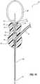
- FIG. 7is a partial perspective view and partial cross-sectional side view of a flexible catheter 90 according to at least one embodiment.
- flexible catheter 90may comprise an elongated lumen 94 extending between a first opening 91 and a second opening 93.
- Flexible catheter 90may also comprise, proximate to second opening 93, a tapered transition region 95.
- tapered transition region 95may comprise a first tapered sub-region 96 and a second tapered sub-region 98.
- second tapered sub-region 98is tapered more sharply than first tapered sub-region 96.
- tapered transition region 95may comprise a single taper and at least one arcuate surface.
- Exemplary flexible catheter 90may also comprise at least one aperture 92 defined within flexible catheter 90 proximate second opening 93.
- aperture 92is defined through the tubular body of flexible catheter 90 to provide a fluid communication path between first opening 91 and aperture 92 through lumen 94.
- flexible catheter 90may comprise any number or combination of suitable materials known to those of skill in the art, including, for example, TECOTHANE ( e . g ., TECOTHANE ® TT1055 D).
- FIGS. 8A and 8Bare assembled perspective and cross-sectional views, respectively, of the exemplary infusion system 10 illustrated in FIG. 1 .
- slender pointed element 22may extend through safety clip 30, through aperture 47 of cap element 46, and into flexible catheter 90.
- the length of slender pointed element 22is chosen such that, when insertion assembly 20 is coupled to the hub body 50 of exemplary hub 40, the pointed end 25 of slender pointed element 22 extends beyond the second opening 93 of flexible catheter 90.
- slender pointed element 22 and flexible catheter 90provide, in combination, a rigid, pointed structure capable of penetrating the septum of an implanted device, such as septum 326 of the exemplary access port 320 illustrated in FIG. 1 .
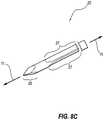
- FIGS. 8C and 8Dare perspective and end views, respectively, of a slender pointed element 22 according to at least one embodiment.
- slender pointed element 22may be structured to enable fluid communication within flexible catheter 90. More particularly, slender pointed element 22 may be sized to allow for clearance between an exterior surface of slender pointed element 22 and an interior surface ( i.e., lumen 94) of flexible catheter 90.
- slender pointed element 22may comprise at least one longitudinally extending indentation 27 defined along at least a portion of the length of slender pointed element 22.
- slender pointed element 22may comprise a plurality of longitudinally extending indentations 27 defined along a longitudinal axis 11 of slender pointed element 22.
- longitudinally extending indentations 27may be defined along the generally circular slender pointed element 22 so as to form a substantially triangular cross section.
- FIG. 8Eis a cross-sectional side view of a slender pointed element 22 positioned within an exemplary flexible catheter 90.
- slender pointed element 22may be configured such that its pointed end 25 extends from second opening 93 of flexible catheter 90.
- slender pointed element 22 and flexible catheter 90may be sized such that, when slender pointed element 22 is fully inserted within flexible catheter 90, the exterior surface of slender pointed element 22 snugly fits within and contacts the interior surface of flexible catheter within region 101.
- longitudinally extending indentations 27may be sized and positioned to provide a fluid communication path between apertures 92 and first opening 91 of flexible catheter 90. In other words, longitudinally extending indentations 27 may provide a fluid communication path within an annulus 103 defined by the exterior surface of slender pointed element 22 and the interior surface ( i.e ., lumen 94) of flexible catheter 90.
- FIG. 9Aillustrates various exemplary geometrical attributes of a longitudinally extending indentation defined along a slender pointed element according to at least one embodiment.
- the cross-sectional area defined between an exterior surface of slender pointed element 22 and an interior surface of flexible catheter 90(hereafter, "the total effective cross-sectional area of annulus 103") may be sized so as to approximate the cross-sectional area of a selected hollow needle gauge.
- Ris the radius of the circle (i.e., an interior surface of cylindrical flexible catheter 90) and r is a perpendicular distance from the center of the circle to the outer circumference of the circle.
- longitudinally extending indentations 27may be sized such that the total effective cross-sectional area of annulus 103 (represented by reference numeral Ac in FIGS. 9B and 9C ) may approximate the cross-sectional area of a selected hollow needle gauge.
- the approximate cross-sectional area of a 22 gauge needlemay be approximated by forming three chord-shaped longitudinally extending depressions 27 to a depth of 0.0047 inches within a cylindrical slender pointed element 22 having a diameter of 0.028 inches.
- FIG. 9Bthe approximate cross-sectional area of a 22 gauge needle may be approximated by forming three chord-shaped longitudinally extending depressions 27 to a depth of 0.0047 inches within a cylindrical slender pointed element 22 having a diameter of 0.028 inches.
- the approximate cross-sectional area of a 25 gauge needlemay be approximated by forming three chord-shaped longitudinally extending depressions 27 to a depth of 0.0024 inches within a cylindrical slender pointed element 22 having a diameter of 0.028 inches.
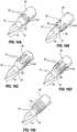
- FIGS. 10A-10Eare perspective views of various exemplary embodiments of a flexible catheter 90.
- one or more apertures 92may be defined within flexible catheter 90 proximate a second opening 93. More particularly, as illustrated in FIGS. 10A-10D , one or more of apertures 92 may be generally circular, oval, or elongated in shape and may be formed within or proximate to tapered transition region 95.
- flexible catheter 90may comprise a permeable region 97 defined proximate second opening 93. In at least one embodiment, permeable region 97 is configured to allow fluids, such as blood, to pass therethrough.
- slender pointed element 22may be formed in a variety of shapes and configurations.
- slender pointed element 22may be formed to have a substantially triangular cross-section (as illustrated in FIG. 11B ), a substantially cross-shaped cross-section (as illustrated in FIG. 11D ), a substantially star-shaped cross-section (as illustrated in FIG. 11F ), and/or a substantially circular cross-section (as illustrated in FIG. 11H ).
- the total effective cross-sectional area of an annulus 103 defined by the interior surface of a flexible catheter 90 and the exterior surface of slender pointed element 22 positioned within the flexible cathetermay be varied by varying the cross-sectional shape and size of slender pointed element 22.
- flexible catheter 90may be configured to allow fluid communication between an exterior surface of slender pointed element 22 and an interior surface of flexible catheter 90. In a particular embodiment, there is no need to remove material from slender pointed element 22 to provide fluid communication between the interior surface of flexible catheter 90 and the exterior surface of slender pointed element 22.
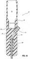
- FIGS. 12A and 12Bare cross-sectional and perspective views, respectively, of an additional embodiment of a slender pointed element 22 positioned within an exemplary flexible catheter 90.
- slender pointed element 22may comprise a solid pointed end 25 and a lumen 105 defined within at least a portion of the body of slender pointed element 22.
- a plurality of apertures 108 defined within slender pointed element 22may provide fluid communication between one or more apertures 92 defined through flexible catheter 90 and lumen 105 of slender pointed element 22.
- fluidmay flow through at least one aperture 92 defined through flexible catheter 90 and through a corresponding aperture 108 defined in slender pointed element 22.
- annulus 103may be omitted, if desired.
- apertures 108may be defined such that, when insertion assembly 20 is coupled to hub 40, apertures 108 are positioned proximate manifold element 61 of hub 40.
- fluidmay flow through apertures 92 and 108, into lumen 105, through an aperture 33 defined in slender pointed element 22 and a corresponding aperture 37 defined in flexible catheter 90, through opening 53 of manifold element 61, out of opening 49 of manifold element 49, and into an extension tube, such as extension tube 70.
- Such a configurationmay be desirable for providing a simple and robust fluid communication path between extension tubing 70 and an internal fluid chamber of an implanted device, such as chamber 324 of exemplary access port 320.
- FIG. 13is a partial cross-sectional side view of an additional embodiment of a flexible catheter 90.
- flexible catheter 90may further comprise a reinforcing member 102.
- reinforcing member 102may be at least partially imbedded within flexible catheter 90.
- Reinforcing member 102may also comprise a coiled, stainless steel wire (formed of, for example, AISI 304 stainless steel) and may have a generally circular, generally oval, rectangular, triangular, or otherwise shaped cross-section.
- reinforcing member 102may be coiled within flexible catheter 90 to extend in a substantially spiral or helical fashion.
- Reinforcing member 102may also be structured for, among other reinforcing functions, resisting external radial forces applied to flexible catheter 90, thereby helping to prevent the inward collapse of flexible catheter 90. In addition, reinforcing member 102 may ameliorate kinking of flexible catheter 90. Reinforcing member 102 may also be sized and positioned within flexible catheter 90 so as to avoid intersecting with apertures 92 defined in flexible catheter. In this exemplary embodiment, apertures 92 may be formed through flexible catheter 90 by drilling or punching out portions of flexible catheter 90, or as otherwise known in the art. Optionally, apertures 92 may be defined through coiled reinforcing member 102 if necessary or desirable.
- hub 40may be configured to have a substantially pear-shaped cross-section.
- hub 40may generally comprise a hub body 50, a recess 42 configured to receive a safety clip, and a sleeve 120 positioned about a septum 48.
- a retaining lip 43may be provided within recess 42 for retaining a safety clip, such as safety clip 30, therein.
- An anchor element 126may also be positioned within and securely affixed to hub body 50.
- flexible catheter 90may be affixed to anchor element 126 to effectively secure flexible catheter 90 within hub body 50.
- extension tube 70may be affixed to and positioned at least partially within hub body 50.
- a channel 122may be defined within hub body 50 and structured to extend between the lumen of extension tube 70 and the lumen of flexible catheter 90 to provide a fluid communication path between extension tube 70 and flexible catheter 90.
- Exemplary sleeve 120may also be positioned about septum 48 and securely affixed to hub body 50. In at least one embodiment, sleeve 120 compresses septum 48 to help seal the various perforations formed in septum 48 by slender pointed element 22.
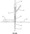
- FIG. 14Bis a simplified cross-sectional side view of an exemplary insertion assembly 20 positioned within the exemplary hub 40 illustrated in FIG. 14A .
- insertion assembly 20generally comprises a slender pointed element 22 and a base member 28 configured in accordance with one or more of the exemplary embodiments described and/or illustrated herein.
- insertion assembly 20may be coupled to hub 40 via a coupling structure 26, a coupling recess 44, and a retaining lip 43.
- FIG. 15is a simplified cross-sectional side view of an additional embodiment of an infusion system 10 comprising an insertion assembly 20, a hub 40, a flexible catheter 90, and an extension tube 70.
- hub 40may comprise a recess 42, a sleeve 120, and a septum 48.
- at least a portion of both extension tube 70 and flexible catheter 90may extend within hub body 50.
- at least a portion of flexible catheter 90may extend within extension tube 70.
- extension tube 70may be configured to receive and surround at least a portion of flexible catheter 90.
- slender pointed element 22may penetrate and pass through flexible catheter 90, extension tube 70, or both, as illustrated in FIG. 15 .
- sleeve 120may compress septum 48 to aid in sealing septum 48 upon removal of slender pointed element 22 from flexible catheter 90 and/or extension tube 70.
- a single tubular elementmay extend through hub 40 and function as both flexible catheter 90 and extension tube 70.
- hub 40may be formed in any number of shapes and sizes.
- hub 40may be substantially cylindrical in shape (as illustrated in FIG 16 ), substantially dome-shaped (as illustrated in FIGS. 19A-19C ), substantially wing-shaped (as illustrated in FIGS. 20A-20B and 21A-21E ), substantially rectangular or square-shaped (as illustrated in FIGS. 22A-22B and 25A-25B), substantially oblong or oval-shaped (as illustrated in FIGS. 26A-26C , 27A-27B , and 33A-33C ), or formed in any other number of suitable shapes and sizes.
- the various possible shapes and configurations of hub 40 and insertion assembly 20may provide various advantages, such as ease of handling by a user and/or compatibility with additional structures.
- FIGS. 17A and 17Bare perspective views of an additional embodiment of an infusion system.
- this exemplary infusion systemmay comprise an insertion assembly 20, a hub 40, a flexible catheter 90, an extension tube 70, a clamp 60, and a tube connector 80.
- the exemplary infusion system illustrated in these figuresfurther comprises a pad member 150 comprising a receiving enclosure 152 configured to receive and at least partially enclose hub 40.
- receiving enclosure 152may comprise a pair of opposing retaining walls 155 sized and configured to receive and at least partially enclose a hub, such as hub 40 in FIG. 17B .
- Receiving enclosure 152may also comprise a rounded channel 156 structured and sized to receive at least a portion of flexible catheter 90. In certain embodiments, rounded channel 156 may aid in ameliorating kinking of extension tube 70 or flexible catheter 90 by preventing sharp bends of flexible catheter 90.
- Pad member 150may also comprise an access notch 158 for positioning pad member 150 about flexible catheter 90.
- flexible catheter 90may have a length that exceeds an anticipated insertion length such that, when flexible catheter 90 is fully inserted into a device (such as exemplary access port 320) implanted within a patient, a bendable portion 147 of flexible catheter 90 extends from a skin surface of the patient. More specifically, the length of flexible catheter 90 may be selected such that a portion 147 of the flexible catheter 90 extending outwardly from the skin surface of a patient (such as skin surface 310 illustrated in FIG. 1 ) may be bent or curved.
- This exemplary configurationmay provide an infusion system that facilitates favorable placement of a hub.
- flexible catheter 90may be bent so that hub 40 may lie against the surface of the skin or may be otherwise positioned as desired.
- flexible catheter 90may be bent to allow hub 40 to be positioned within receiving enclosure 152.
- Pad 150may then placed on and/or affixed or taped to the skin surface of a patient.
- the exemplary infusion system illustrated in FIG. 17Bthus represents a relatively low profile apparatus for accessing an implanted device.
- pad member 150may comprise a receiving enclosure that is configured to accept and retain a hub (of any geometry), an extension tube, a flexible catheter, or combinations thereof, without limitation.
- a sleeve member 160may surround at least a portion of flexible catheter 90.
- sleeve member 160may be configured to surround the portion of flexible catheter 90 that extends between hub 40 and pad member 150.
- sleeve member 160may be folded or creased ( e.g ., with accordion-type folds) to permit the vertical movement of hub 40 relative to pad member 150.
- sleeve member 160may protect flexible catheter 90, conceal blood traveling through flexible catheter 90 (if flexible catheter 90 is at least partially transparent), or ameliorate kinking of flexible catheter 90.
- FIGS. 19A and 19Bare perspective and cross-sectional side views, respectively, of an additional embodiment of an infusion system 10 comprising an insertion assembly 20, a hub 40, a flexible catheter 90, an extension tube 70, a clamp 60, and a tube connector 80.
- hub 40may comprise a recess 42 defined within a hub body 50 and a sleeve 120 surrounding a septum 48 positioned within recess 42.
- fluid communication between extension tube 70 and flexible catheter 90is provided through a channel 166 formed within hub body 50.
- channel 166may be formed after flexible catheter 90 and extension tube 70 have been affixed or molded within hub body 50.
- a machine toolsuch as a drill bit or milling bit, may pass within extension tube 70, through a portion of hub body 50, and into flexible catheter 90 to form channel 166 and an aperture in flexible catheter 90.
- a displacementmay be positioned within extension tube 70 and into a preformed aperture in flexible catheter 90, and then hub body 50 may be formed or molded around the assembly.
- FIG. 19Cis a cross-sectional side view of an additional embodiment of an infusion system.
- the vertical (i.e ., along the axis of slender pointed element 22) height of hub 40may be reduced by reducing the vertical height of recess 42 and safety clip 30.
- the size and configuration of each component of each exemplary embodiment described and/or illustrated hereinmay be varied, modified, or otherwise selected, without limitation.
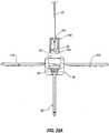
- FIGS. 20A-20Bare perspective and cross-sectional side views, respectively, of an additional embodiment of an infusion system 10 comprising an insertion assembly 20, a hub 40, a flexible catheter 90, an extension tube 70, a clamp 60, and a tube connector 80.
- hub 40may generally comprise a hub body 50, a manifold element 61, and a septum 48 compressed by hub body 50 (thus eliminating the need for a sleeve, such as sleeve 120).
- Hub 40may also comprise a plurality of wing structures 41A and 41B configured to affix hub 40 to the skin of a patient.
- hub 40may comprise a coupling recess 44 configured to receive a complimentary coupling structure 26 provided on base member 28 of insertion assembly 20.
- Hub 40may also comprise a recess 42 having a retaining lip 43 for retaining at least a portion of a safety clip, such as safety clip 30, within recess 42.
- a channel 166 extending from extension tube 70 to an upper end of flexible catheter 90may also be defined within hub body 50 for providing fluid communication between extension tube 70 and flexible catheter 90.
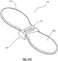
- FIGS. 21A-21Eare perspective and cross-sectional views of various exemplary components of an additional embodiment of an infusion system 10.
- exemplary infusion system 10may comprise an insertion assembly 20, a hub 40, a flexible catheter 90, an extension tube 70, a clamp 60, and a tube connector 80.
- infusion system 10may also comprise a winged component 170 positioned between insertion assembly 20 and hub 40.
- winged component 170may comprise a coupling recess 172 defined within a body 174.
- a plurality of wing structures 41A and 41Bmay extend from body 174, as shown in FIG. 21C .
- coupling recess 172may be configured to receive a complimentary coupling structure 26 provided on a base member 28 of insertion assembly 20.
- hub 40may comprise an opening 178 for accepting the body 174 of winged component 170.
- Hub 40may also comprise a recess 42 and wing-shaped depressions 177 for accepting wing structures 41A and 41B of winged component 170.
- winged component 170may be affixed to hub 40 by any means known to those of skill in the art, including, for example, by adhering body 174 within opening 178 of hub 40 using an adhesive.
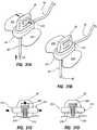
- FIGS. 22A-22Bare cross-sectional side views of an exemplary safety clip housing 240.
- Safety clip housing 240generally represents any structure configured to at least partially enclose a safety clip of any shape or size; including, for example, the various safety clip embodiments described and/or illustrated herein.
- safety clip housing 240may be configured to house a substantially rectangular safety clip 30.
- safety clip housing 240may comprise a hole 242 sized for receiving a slender pointed element, such as slender pointed element 22.
- Safety clip housing 240may also comprise a base member 244 sized to fit within a recess 42 defined in hub 40, as illustrated in FIG. 22B .
- FIGS. 23A and 23Bare perspective views of an additional embodiment of a safety clip 30.
- Safety clip 30generally represents any self-actuating device for capturing a pointed end of a slender pointed element, such as pointed end 25 of slender pointed element 22 illustrated in FIG. 3A .
- safety clip 30may comprise a plurality of legs 32A and 32B having curved end regions 35A and 35B, respectively, and a hole 34 sized for receiving a slender pointed element, such as slender pointed element 22.
- safety clip 30may be sized to fit within a recess defined in an insertion assembly, such as recess 24 defined in insertion assembly 20 illustrated in FIG. 3B .
- Safety clip 30may also be sized to fit within a recess defined in a hub of an infusion system, such as recess 42 of hub 40, or sized to fit within a safety clip housing, such as safety clip housing 240.
- safety clip 30is attached to slender pointed element 22 by passing the pointed end 25 of slender pointed element 22 through hole 34 of safety clip 30, past legs 32A and 32B, and past curved end regions 35A and 35B. Once pointed end 25 of slender pointed element 22 has passed curved end regions 35A and 35B, legs 32A and 32B may clamp around slender pointed element 22 to removably affix the safety clip to slender pointed element 22. As slender pointed element 22, together with safety clip 30, is inserted into recess 42 defined in hub body 50, slender pointed element 22 may continue through safety clip 30 and into a sealable path defined in a hub body, such as hub body 50.
- legs 32A and 32B of safety clip 30may be biased such that, upon removal of slender pointed element 22 from the sealable path defined in hub body 50, curved end regions 35A and 35B may close around the pointed end 25 of slender pointed element 22 to retain the pointed end 25 within the body of safety clip 30.
- a safety clip 30may prevent inadvertent insertion of slender pointed element 22 into another person, such as a medical practitioner utilizing infusion system 10.
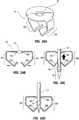
- FIGS. 24A-24Dare perspective and cross-sectional side views of an additional embodiment of a safety clip 30.
- safety clip 30may comprise a hole 34 sized for receiving a slender pointed element (such as slender pointed element 22), a first leg 32A comprising an upper arm portion 35A and a lower arm portion 39A, and a second leg 32B comprising an upper arm portion 35B and a lower arm portion 39B.
- safety clip 30may be sized to fit within a recess defined in an insertion assembly, such as recess 24 defined in insertion assembly 20 illustrated in FIG. 3B .
- Safety clip 30may also be sized to fit within a recess defined in a hub of an infusion system, such as recess 42 of hub 40, or sized to fit within a safety clip housing, such as safety clip housing 240.
- upper arm portions 35A and 35B and lower arm portions 39A and 39B of safety clip 30may be configured to retain the pointed end 25 of slender pointed element 22 within the body of safety clip 30.
- legs 32A and 32B of safety clip 30may be biased such that, upon removal of slender pointed element 22 from hub body 50, lower arm portions 39A and 39B may close around the pointed end 25 of slender pointed element 22 to retain the pointed end 25 within the body of safety clip 30.
- upper arm portions 35A and 35Bmay be configured to prevent a protrusion 45 provided on slender pointed element 22 from passing upwards through hole 34.
- lower arm portions 39A and 39Bmay be configured to allow the protrusion 45 provided on slender element 22 to enter the body of safety clip 30, but to prevent the protrusion 45 from passing downwards past lower arm portions 39A and 39B.
- a safety clip 30may prevent inadvertent insertion of slender pointed element 22 into another person, such as a medical practitioner utilizing infusion system 10.
- a safety clip housingsuch as safety clip housing 240 illustrated in FIGS. 22A-22B .
- a safety clip housingmay be attached or affixed to a slender pointed element, to a hub, or both, in any number of ways.
- a safety clip housing 240may be configured to be removably attachable to a portion of a hub 40.
- safety clip housing 240may comprise a base member 244 configured to snap-fit over a plurality of complimentary protrusions 250 provided on hub 40.
- base member 244 of safety clip housing 240may be positioned and permanently adhered within a recess 42 provided in hub 40.
- FIGS. 26A-26Care perspective views of an additional embodiment of an infusion system comprising an insertion assembly 20, a hub 40, a flexible catheter 90, an extension tube 70, and a tube connector 80.
- a removable member 180 in fluid communication with extension tube 70may be configured to be removably attachable to a hub body 50 of hub 40.
- hub body 50may comprise one or more coupling recesses 192 configured to receive complimentary coupling structures 182 provided on removable member 180.
- removable member 180may be coupled to hub body 50 by positioning coupling structures 182 within complimentary coupling recesses 192.
- removable member 180may also comprise a pointed tubular element 184 in fluid communication with extension tube 70.
- pointed tubular element 184may be configured to penetrate a penetrable septum 194 provided within hub body 50.
- penetrable septum 194seals a tubing portion 196 in fluid connection with flexible catheter 90.
- a fluid communication path between flexible catheter 90 and extension tube 70may be established by inserting tubular element 184 through septum 194 and into tubing portion 196 housed in hub body 50.
- extension tube 70may be removably attached to hub 40 and/or flexible catheter 90 in any number of ways.
- extension tube 70may be removably attached to the hub body 50 of hub 40 by positioning a male tube connector 202 provided on hub body 50 within a complimentary female tube connector 204 attached to extension tube 70.
- complimentary tube connectors 202 and 204represent any form of tubing connection or mechanism known to those of skill in the art; including, for example, a so-called Luer-type fitting or connector.
- male tube connector 202may be positioned within a recess 206 defined within hub body 50 of hub 40, as illustrated in FIG. 27B .
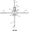
- FIGS. 28A and 28Bare perspective and cross-sectional views, respectively, of an infusion system according to an additional embodiment.
- this exemplary infusion systemmay comprise an insertion assembly 20, a base member 40, a flexible catheter 90, and an extension tube 70.
- a cap element 46may be inserted within a recess 42 defined in hub body 50.
- Cap element 46generally represents any structure or device capable of sealing any aperture or recess defined within any of the components of the exemplary embodiments described and/or illustrated herein.
- cap element 46may be positioned above septum 48 and configured to seal recess 42 from the environment, thereby preventing bacteria from entering and forming within recess 42.
- a cap element 46is disposed within each exposed recess and/or aperture defined in each component of exemplary infusion apparatus 10.
- Cap element 46may be formed of any suitable material capable of sealing an aperture or recess; including, for example, medical-grade polymers (such as silicone) and monomers (such as Ethylene Propylene Diene Monomer (“EPDM”), or other suitable materials.
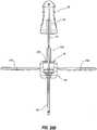
- FIG. 29illustrates an exemplary slender pointed element 22 comprising a pointed end 25.
- the pointed end 25 of slender pointed element 22may be scored or otherwise weakened along line 23. Accordingly, upon completion of an infusion operation, the pointed end 25 of slender pointed element 22 may break off along line 23 upon removal of slender pointed element 22 from hub body 50, leaving the broken pointed end 25 of slender pointed element 22 within septum 48.
- At least a portion of slender pointed element 22may be retractable into a recess defined in insertion assembly 20.
- a lever 200 coupled to slender pointed element 22may be provided in a recess 29 defined in base member 28 of insertion assembly 20.
- lever 200may be manipulated from a first position illustrated in FIG. 30A to a second position illustrated in FIG. 30B to retract at least a portion of slender pointed element 22 within base member 28.
- a blood drawmay be attempted to ensure the proper placement of flexible catheter 90 within the implanted device.
- buttons 210 and 214may comprise cantilevered end portions 212 and 216, respectively, that are configured to manipulate a complimentary cantilevered end portion 220 of slender pointed element 22 generally upwards within a recess defined in base member 28.
- slender pointed element 22may be retracted into base member 28 by manipulating wing structures 41A and 41B from a first position, illustrated in FIGS.
- wing structures 41A and 41Bmay comprise cantilevered end portions 230A and 230B, respectively, that are configured to manipulate slender pointed element 22 generally upwards within a recess defined in base member 28.
- FIGS. 33A-33Care perspective views of an additional embodiment of an infusion apparatus 10.
- infusion apparatus 10may comprise an insertion assembly 20, a hub 40, a flexible catheter 90, an extension tube 70, a clamp 60, and a tube connector 80.
- Insertion assembly 20may comprise a biasing member 232 positioned around a slender pointed element 22 and positioned proximate a safety clip 30.
- biasing member 232may bias safety clip 30 away from insertion assembly 20 such that, upon removal of insertion assembly 20 from hub 40, safety clip 30 may positioned around a pointed end 25 of slender pointed element 22 by biasing member 232.
- insertion assembly 20may also comprise a plurality of coupling arms 234 that define a recess 236 that is configured to receive at least a portion of hub 40.
- hub 40may be sized and shaped so as to fit within the recess 236 defined within insertion assembly 20 by coupling arms 234.
- the exemplary configuration of infusion system 10 in FIGS. 33A-33Cmay provide various advantages, such as ease of handling by a user and/or compatibility with additional structures.
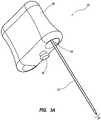
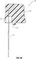
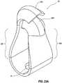
- FIGS. 34A-34Care perspective views of an exemplary hub 40 for an infusion system according to an additional embodiment.
- exemplary hub 40may comprise a plurality of wing structures 41A and 41B.
- wing structures 41A and 41Bare configured to affix exemplary hub 40 to the skin of a patient.
- wing structures 41A and 41Bmay be taped, adhesively affixed, or otherwise attached to the surface of a patient's skin, such as skin surface 310 in FIG. 1 .
- a sheet of materialsuch as TEGADERM ® , may be used to affix hub 40 to the surface of a patient's skin.
- hub 40may comprise a recess 260 and a receiving enclosure 264.
- recess 260is sized and configured to receive at least a portion of a flexible catheter, such as flexible catheter 90 in FIGS. 34B-34C .
- receiving enclosure 264may be sized and configured to retain at least a portion of a flexible catheter, such as flexible catheter 90 in FIGS. 34B-34C .
- wing structures 41A and 41B of hub 40may be configured to fold inwardly along a folding line 266. As best seen in FIGS.
- wing structures 41A and 41Bmay be folded inwardly upward.
- wing structures 41A and 41Bmay be affixed to a patient's skin when in a downward, extended position, illustrated in FIG. 34B .
- flexible catheter 90 and/or a slender pointed element, such as slender pointed element 22 in FIG. 3Amay be removed from hub 40 when wing structures 41A and 41B are in an upward, folded position, illustrated in FIG. 34C .
- a method of accessing an implanted device using a infusion systemmay comprise: 1) positioning at least a portion of slender pointed element 22 within flexible catheter 90; 2) penetrating a septum of an implanted device, such as septum 326 of access port 320, using the slender pointed element 22 positioned within the flexible catheter 90; and 3) positioning at least a portion of flexible catheter 90 within the implanted device.
- a clinicianmay grasp base member 28 of insertion assembly 20 and may guide the pointed end 25 of slender pointed element 22 into recess 42 of hub 40, through septum 48, and into flexible catheter 90. The clinician may then guide the pointed end 25 of slender pointed element 22 (positioned within flexible catheter 90) through the skin surface 310 and subcutaneous zone 312 of a patient and into a port septum 326. The clinician may then confirm that flexible catheter 90 is positioned within chamber 324 of access port 320 by drawing blood through extension tube 70 using a syringe attached to tube connector 80. Thus, blood may be drawn through apertures 92 of flexible catheter 90 and through at least one cavity formed between an inner surface of flexible catheter 90 and an outer surface of slender pointed element 22. Blood may then travel through hub 40 ( i.e., manifold element 61) and through extension tube 70 to confirm that slender pointed element 22 and flexible catheter 90 of infusion system 10 are properly placed within port chamber 324.
- hub 40i.e., manifold element 61
- base member 28 of insertion assembly 20may be grasped and slender pointed element 22 may be removed from hub 40, while flexible catheter 90 may remain positioned within chamber 324 of access port 320.
- Septum 48may seal any hole or aperture created by the removal of slender pointed element 22.
- flexible catheter 90may be positioned or oriented in any number of ways; including for example, by positioning flexible catheter 90 substantially perpendicularly to skin surface 310.
- Safety clip 30may remain attached to hub 40 ( i.e., within recess 42) until the pointed tip 25 of slender pointed element 22 becomes encased by safety clip 30 (via movement of legs 32A and 32B), after which time safety clip 30 may be removed from recess 42 of hub 40.
- Hub 40, extension tube 70, tube connector 80, or combinations thereofmay then be taped to skin surface 310 of the patient.
- wing structures 41A and 41Bmay be adhesively affixed to skin surface 310.
- each of the exemplary infusion system embodiments described and/or illustrated hereinmay provide vascular access (via an implanted device) for any number of procedures; including, for example, infusion, blood aspiration, hemodialysis, hemofiltration, peritoneal dialysis, or other procedures as known in the art.
- the use of sharp implementsmay be reduced or eliminated, thereby reducing the danger of inadvertent sticks or punctures.
- each component in each exemplary embodiment described and/or illustrated hereinmay be formed in any number of suitable shapes, sizes, and configurations.
- the various infusion system embodiments described hereinmay be adapted for use in connection with high pressure operations, commonly referred to as "power injection" processes.
- the various components of the exemplary embodiments provided hereinmay be adapted to handle pressure of about 27,579 Bar (400 psi) or higher.
Landscapes
- Health & Medical Sciences (AREA)
- Life Sciences & Earth Sciences (AREA)
- Heart & Thoracic Surgery (AREA)
- Hematology (AREA)
- Engineering & Computer Science (AREA)
- Anesthesiology (AREA)
- Biomedical Technology (AREA)
- Animal Behavior & Ethology (AREA)
- General Health & Medical Sciences (AREA)
- Public Health (AREA)
- Veterinary Medicine (AREA)
- Pulmonology (AREA)
- Biophysics (AREA)
- Gastroenterology & Hepatology (AREA)
- Vascular Medicine (AREA)
- Infusion, Injection, And Reservoir Apparatuses (AREA)
Description
- Access to a patient's vascular system may be established by a variety of temporary or permanently implanted devices. For example, temporary access to a patient's vascular system may be accomplished by the direct percutaneous introduction of a needle into the patient's blood vessel. While such a temporary and direct approach may be relatively simple and suitable for applications that are limited in frequency or duration, such as intravenous feeding and/or intravenous drug delivery, this temporary approach may not be suitable for procedures that are frequently repeated or that require vascular access for relatively long time periods of time, such as hemodialysis or other similar extracorporeal procedures.
- Accordingly, a variety of implantable devices have been proposed to provide a convenient method for repeatedly introducing fluids, such as medicaments, into the vasculature of a patient. Typically, such implantable device comprise a housing that encloses an internal fluid chamber or cavity. An access aperture defined through the housing and sealed by a penetrable septum provides access to the internal fluid chamber, which is typically in fluid communication with an implanted catheter attached to a patient's vasculature.
- Quantities of fluid, such as medication, blood, or the like, may be introduced into, or withdrawn from, a patient's vasculature using conventional implantable device by: 1) penetrating the septum of the implanted device using a percutaneously inserted needle; 2) positioning at least the tip of the needle within the internal fluid reservoir or cavity enclosed in the device housing; and 3) discharging fluids through the needle into the internal fluid cavity. The discharged fluids may then be directed through the distal end of the implanted catheter connected to the implanted device to an entry point into the venous system of the body of the patient. Blood may also be aspirated through the implanted device in a similar manner.
US 5 176 662 A discloses an infusion apparatus according to the preamble of claim 1.- In at least one embodiment, an infusion apparatus for providing access to an implanted device, such as an access port or a pump (e.g., a so-called pain pump) is provided as mentioned in claim 1. The apparatus may comprise an insertion assembly, a hub comprising a sealable path configured to receive at least a portion of the insertion assembly, a flexible catheter attached to the hub and configured to receive at least a portion of the insertion assembly, and an extension tube attached to the hub. In certain embodiments, the hub may comprise a plurality of wing structures and may be configured to provide fluid communication between the flexible catheter and the extension tube. The hub may also comprise a manifold element structured to provide fluid communication between the flexible catheter and the extension tube. In addition, the sealable path may comprise a septum configured to seal the sealable path upon removal of the insertion assembly from the flexible catheter. The extension tube may either be permanently or removably attached to the hub.
- According to at least one embodiment, the insertion assembly may comprise a slender pointed element and both the sealable path and the flexible catheter may be configured to receive at least a portion of the slender pointed element. Similarly, the extension tube may be configured to receive at least a portion of the slender pointed element. The flexible catheter may also comprise at least one aperture defined proximate a distal end of the flexible catheter and the slender pointed element may comprise at least one longitudinally extending indentation defined along the slender pointed element. In at least one embodiment, a cross-sectional area defined between an exterior surface of the slender pointed element and an interior surface of the flexible catheter may approximate the cross-sectional area of a hollow needle gauge. In addition, the flexible catheter may comprise at least one aperture defined proximate a distal end of the flexible catheter and the slender pointed element may be at least partially hollow and comprise at least one aperture defined within the slender pointed element for communicating fluid with the at least one aperture defined in the flexible catheter.
- In certain embodiments, at least a portion of the slender pointed element may be retractable into a recess defined in the insertion assembly. In addition, the flexible catheter may have a length that exceeds an anticipated insertion length such that, when the flexible catheter is fully inserted into a device implanted within a patient, a bendable portion of the flexible catheter may extend from a skin surface of the patient. The infusion apparatus may also comprise a receiving enclosure positioned substantially parallel to a skin surface of a patient and configured to receive at least a portion of the
hub. Further, the infusion apparatus may comprise a safety clip configured to: 1) retain a pointed end of the slender pointed element within the safety clip when the slender pointed element is removed from the hub; and 2) allow the pointed end of the slender pointed element to pass through the safety clip when the slender pointed element is inserted into the hub. The infusion apparatus may also comprise a reinforcing member, which may be coiled, at least partially imbedded within the flexible catheter. - In at least one embodiment, an infusion device for use with an implanted device may comprise a slender pointed element comprising a pointed end, a flexible catheter comprising a sealable path configured to receive at least a portion of the slender pointed element, and an extension tube in fluid communication with the flexible catheter. In certain embodiments, the sealable path may be structured to seal upon removal of the slender pointed element from the flexible catheter.
- In addition, an infusion apparatus for accessing an implanted device may comprise an insertion assembly comprising a slender pointed element, a hub comprising a sealable path configured to receive at least a portion of the slender pointed element, a flexible catheter attached to the hub and configured to receive at least a portion of the slender pointed element, and an extension tube attached to the hub. In certain embodiments, the hub may comprise a manifold element structured to provide fluid communication between the flexible catheter and the extension tube, and a septum configured to seal the sealable path upon removal of the slender pointed element from the flexible catheter.
- In at least one embodiment, a method of providing a fluid communication path to an implanted device may comprise positioning at least a portion of a slender pointed element within a flexible catheter, penetrating a septum of an implanted device with the slender pointed element positioned within the flexible catheter, positioning at least a portion of the flexible catheter within the implanted device, removing the slender pointed element from the flexible catheter, and retaining at least a portion of the flexible catheter within the implanted device. The method may also comprise providing a hub in fluid communication with the flexible catheter, and removably attaching an extension tube to the hub to provide fluid communication between the flexible catheter and the extension tube. In addition, the method may comprise sealing a sealable path defined in the hub upon removal of the slender pointed element from the flexible catheter.
- In certain embodiments, this exemplary method may further comprise positioning at least a portion of the slender pointed element within the extension tube. In addition, this method may further comprise retracting at least a portion of the slender pointed element into the flexible catheter. The method may also further comprise providing a safety clip proximate a pointed end of the slender pointed element, and retaining the pointed end of the slender pointed element within the safety clip upon removal of the slender pointed element from the flexible catheter.
- Features from any of the above-mentioned embodiments may be used in combination with one another in accordance with the general principles described herein. These and other embodiments, features and advantages will be more fully understood upon reading the following detailed description in conjunction with the accompanying drawings and claims.
- The accompanying drawings illustrate a number of exemplary embodiments and are a part of the specification. Together with the following description, these drawings demonstrate and explain various principles of the instant disclosure.
FIG. 1 is a schematic cross-sectional side view of an exemplary device implanted within a patient;FIG. 2 is an exploded perspective view of an exemplary infusion system according to at least one embodiment;FIG. 3A is a perspective view of an exemplary insertion assembly according to at least one embodiment;FIG. 3B is a cross-sectional side view of the exemplary insertion assembly illustrated inFIG. 3A ;FIG. 4A is a perspective view of an exemplary hub according to at least one embodiment;FIG. 4B is a cross-sectional side view of the exemplary hub illustrated inFIG. 4A ;FIG. 4C is a cross-sectional side view of an exemplary flexible catheter and extension tube attached to the exemplary hub illustrated inFIG. 4A ;FIG. 5 is a perspective view of an extension tube, clamp device, and tube connector according to at least one embodiment;FIG. 6 is a perspective view of a safety clip according to at least one embodiment;FIG. 7 is a partial perspective view and partial cross-sectional side view of a flexible catheter according to at least one embodiment;FIG. 8A is an assembled perspective view of the exemplary infusion system illustrated inFIG. 1 ;FIG. 8B is a partial cross-sectional side view of the exemplary infusion system illustrated inFIG. 8A ;FIG. 8C is a partial perspective view of a slender pointed element according to at least one embodiment;FIG. 8D is an end view of the exemplary slender pointed element illustrated inFIG. 8C ;FIG. 8E is a cross-sectional side view of the exemplary slender pointed element illustrated inFIG. 8C positioned within an exemplary flexible catheter;FIG. 9A illustrates various exemplary geometrical attributes of a longitudinally extending indentation defined along a slender pointed element according to at least one embodiment;FIG. 9B is a schematic end view of a slender pointed element according to at least one embodiment;FIG. 9C is a schematic end view of a slender pointed element according to an additional embodiment;FIGS. 10A-10E are perspective views of various exemplary embodiments of a flexible catheter;FIG. 11A is a perspective view of an exemplary embodiment of a slender pointed element;FIG. 11B is a cross-sectional end view of the exemplary slender pointed element illustrated inFIG. 11A , taken along theline 11B-11B;FIG. 11C is a perspective view of an additional embodiment of a slender pointed element;FIG. 11D is a cross-sectional end view of the exemplary slender pointed element illustrated inFIG. 11C , taken along theline 11D-11D;FIG. 11E is a perspective view of an additional embodiment of a slender pointed element;FIG. 11F is a cross-sectional end view of the exemplary slender pointed element illustrated inFIG. 11E , taken along theline 11F-11F;FIG. 11G is a perspective view of an additional embodiment of a slender pointed element;FIG. 11H is a cross-sectional end view of the exemplary slender pointed element illustrated inFIG. 11G , taken along theline 11H-11H;FIG. 12A is a cross-sectional side view of a portion of a slender pointed element and a flexible catheter according to at least one embodiment;FIG. 12B is a schematic perspective view of the exemplary slender pointed element and flexible catheter illustrated inFIG. 12A ;FIG. 13 is a partial cross-sectional side view of an additional embodiment of a flexible catheter;FIG. 14A is a simplified cross-sectional side view of an additional embodiment of a hub;FIG. 14B is a simplified cross-sectional side view of an exemplary insertion assembly positioned within the exemplary hub illustrated inFIG. 14A ;FIG. 15 is a simplified cross-sectional side view of an additional embodiment of an infusion system;FIG. 16 is a simplified cross-sectional side view of an additional embodiment of a hub;FIG. 17A is a perspective view of an exemplary embodiment of a receiving enclosure for use with an infusion system;FIG. 17B is a perspective view of an exemplary infusion system positioned within the exemplary receiving enclosure illustrated inFIG. 17A ;FIG. 18A is a perspective view of an additional embodiment of an infusion system;FIG. 18B is a cross-sectional side view of the exemplary infusion system illustrated inFIG. 18A ;FIG. 19A is a perspective view of an additional embodiment of an infusion system;FIG. 19B is a cross-sectional side view of the exemplary infusion system illustrated inFIG. 19A ;FIG. 19C is a cross-sectional side view of an additional embodiment of an infusion system;FIG. 20A is a perspective view of an additional embodiment of an infusion system;FIG. 20B is a cross-sectional side view of the exemplary infusion system illustrated inFIG. 20A ;FIG. 21A is a perspective view of an additional embodiment of an infusion system;FIG. 21B is a perspective view of a portion of the exemplary infusion system illustrated inFIG. 21A ;FIG. 21C is a perspective view of a portion of the exemplary infusion system illustrated inFIG. 21A ;FIG. 21D is a perspective view of a portion of the exemplary infusion system illustrated inFIG. 21A ;FIG. 21E is a cross-sectional side view of the exemplary infusion system illustrated inFIG. 21A ;FIG. 22A is a cross-sectional side view of an exemplary safety clip housing in a first position;FIG. 22B is a cross-sectional side view of an exemplary safety clip housing in a second position;FIG. 23A is a perspective view of an additional embodiment of a safety clip in a first position;FIG. 23B is a perspective view of an additional embodiment of a safety clip in a second position;FIGS. 24A-24D are perspective and cross-sectional side views of an additional embodiment of a safety clip;FIG. 25A is a cross-sectional side view of an exemplary safety clip housing removably attached to a hub;FIG. 25B is a cross-sectional side view of an exemplary safety clip housing adhered to a hub;FIGS. 26A-26C are perspective views of an infusion system according to an additional embodiment;FIGS. 27A and 27B are perspective views of additional embodiments of an infusion system;FIG. 28A is a perspective view of an infusion system according to an additional embodiment;FIG. 28B is a cross-sectional side view of the exemplary infusion system illustrated inFIG. 28A ;FIG. 29 is a cross-sectional side view of an exemplary slender pointed element comprising a scored pointed end;FIGS. 30A-30B are perspective views of an infusion system according to an additional embodiment;FIGS. 31A-31B are perspective views of an infusion system according to an additional embodiment;FIGS. 31C-31D are cross-sectional side views of the exemplary infusion system illustrated inFIGS. 31A-31B ;FIGS. 32A-32B are perspective views of an infusion system according to an additional embodiment;FIGS. 32C-32D are cross-sectional side views of the exemplary infusion system illustrated inFIGS. 32A-32B ;FIGS. 33A-33C are perspective views of an insertion assembly according to an additional embodiment; andFIGS. 34A-34C are perspective views of an exemplary hub for an infusion system according to an additional embodiment;- Throughout the drawings, identical reference characters and descriptions indicate similar, but not necessarily identical, elements. While the exemplary embodiments described herein are susceptible to various modifications and alternative forms, specific embodiments have been shown by way of example in the drawings and will be described in detail herein. However, one of skill in the art will understand that the exemplary embodiments described herein are not intended to be limited to the particular forms disclosed. Rather, the instant disclosure covers all modifications, equivalents, and alternatives falling within the scope defined by the appended claims.
- Generally speaking, one or more of the exemplary apparatuses, devices, and/or methods described and illustrated herein may be employed for percutaneously accessing a device, such as an access port or pump (e.g., a so-called pain pump), implanted within a patient, such as
exemplary access port 320 illustrated inFIG. 1 .Access port 320 generally represents any device capable of being implanted within a patient, such as an access port, pump, or other device known to those of skill in the art. As illustrated inFIG. 1 ,exemplary access port 320 may comprise ahousing 322 and aseptum 326 defining achamber 324. Acatheter 332 in fluid communication with thevasculature 316 of a patient may be attached tohousing 322 to provide a fluid communication path betweenexemplary access port 320 andvasculature 316. In at least one embodiment,access port 320 is implanted within the interior of a patient; namely, belowskin surface 310 and withinsubcutaneous zone 312. In certain embodiments,access port 320 may be implanted beneathskin surface 310 by a distance in the range from about 3 mm to about 20 mm, and/or from about 5 mm to about 15 mm.Housing 322 ofaccess port 320 may then be secured todeep fascia tissue 314 by a plurality ofsutures 328.Catheter 332 may be surgically implanted, indwelling, or secured within the patient in any other manner known to those of skill in the art. FIG. 2 is an exploded perspective view of anexemplary infusion system 10 for accessing an implanted device, such asexemplary access port 320 illustrated inFIG. 1 . As seen inFIG. 2 ,exemplary infusion system 10 may comprise aninsertion assembly 20, asafety clip 30, ahub 40, aflexible catheter 90, anextension tube 70, aclamp device 60, and atube connector 80. Generally, the various components ofinfusion system 10 may comprise any number or combination of suitable materials known to those of skill in the art, such as metals, plastics, or polymers. For example, the various components ofinfusion system 10 may comprise polytetrafluoroethylene (PTFE), polypropylene, silicone, stainless steel (e.g., AISI 304 stainless steel), fluorinatedethylenepropylene (FEP), perfluoroalkoxy (PFA), ethylenetetrafluoroethylene (ETFE), polyetheretherketone (PEEK®), polyurethane (including thermoplastic polyurethanes, such as ISOPLAST®, TECOFLEX®, TECOTHANE®, CARBOTHANE®, TECOPLAST®, or TECOPHILIC®-type polyurethanes), or any number of combinations thereof.FIGS. 3A and3B are perspective and cross-sectional side views, respectively, of anexemplary insertion assembly 20. As seen in these figures,exemplary insertion assembly 20 may comprise a slenderpointed element 22 attached to abase member 28. Slender pointedelement 22 generally represents any structure capable of penetrating the septum of an implanted device, such asseptum 326 ofaccess port 320. For example, slenderpointed element 22 may represent a trocar, a coring or non-coring needle, a cannula, or any other suitable hollow or solid structure. Slender pointedelement 22 may be entirely solid, entirely hollow, or may include a solidpointed end 25 and an at least partially hollow body, as discussed in greater detail below. In addition, slenderpointed element 22 may comprise any conventional needle, trocar, or cannula material, such as stainless steel (e.g., AISI 304 stainless steel), plastic, or the like.- As seen in
FIGS. 3A and3B , arecess 24 may be defined withinbase member 28. In at least one embodiment,recess 24 is configured to receive one or more structural elements, such as, for example,safety clip 30.Base member 28 may also comprise acoupling structure 26, which generally represents any structure (e.g., a protrusion) or recess capable of couplingbase member 28 to an additional element, such ashub 40. In at least one embodiment,coupling structure 26 couples to acomplimentary coupling recess 44 defined in hub 40 (illustrated inFIGS. 4A-4C ). In certain embodiments,base member 28 may be injection molded or otherwise formed about slenderpointed element 22 so as to capture a portion of slenderpointed element 22 within thebase member 28, as best seen inFIG. 3B . FIGS. 4A and4B are perspective and cross-sectional views, respectively, of anexemplary hub 40 according to at least one embodiment. As seen in these figures,exemplary hub 40 may comprise a plurality ofwing structures hub body 50. In at least one embodiment,wing structures exemplary hub 40 to the skin of a patient. For example,wing structures skin surface 310 inFIG. 1 . Generally speaking,wing structures FIGS. 20A-20B ,22A-22B ,25A-25B ,26A-26C ,27A-27B ,30A-30B ,31A-31B , and33A-33D . As detailed above,exemplary hub 40 andwing structures - As illustrated in
FIG. 4B , in certain embodiments acoupling recess 44 may be defined withinhub body 50 and structured to receive thecomplimentary coupling structure 26 provided onbase member 28. Similarly, arecess 42 may be defined inhub body 50 and configured to receive both a slender pointed element (such as slender pointed element 22) and a safety clip (such as safety clip 30), as discussed in greater detail below. A retaininglip 43 may also be provided withinrecess 42 for retaining a safety clip, such assafety clip 30, withinrecess 42. - In at least one embodiment, a
penetrable septum 48 may be provided inrecess 42 and positioned above amanifold element 61 defined inexemplary hub body 50. Acap element 46 may also be positioned aboveseptum 48 and configured to retainseptum 48 withinrecess 42. As illustrated inFIG. 4B ,manifold element 61 may define aplenum 49 in communication with a plurality of openings (e.g.,openings aperture 47 may also be defined withincap element 46 generally opposite opening 51 ofplenum 49. In certain embodiments,septum 48 may comprise any suitable material capable of suitably sealingopening 51 ofplenum 49; including, for example, medical-grade polymers (such as silicone) and monomers (such as Ethylene Propylene Diene Monomer ("EPDM"), or other suitable materials. - In at least one embodiment,
exemplary hub 40 may be structured to receive at least a portion ofinsertion assembly 20. For example,hub 40 may be configured to receive at least a portion of a slender pointed element, such as slenderpointed element 22, within a sealable path defined withinhub 40. In at least one embodiment, such a sealable path may be defined by, for example,recess 42,aperture 47,septum 48, opening 51, andopening 53. In this example, slenderpointed element 22 may be inserted intoaperture 47 incap element 46 and passed throughseptum 48 andopenings penetrable septum 48 may be configured to sealopening 51 ofplenum 49 upon removal of slenderpointed element 22 fromhub 40. Accordingly, slenderpointed element 22 ofinsertion assembly 20 may be inserted through and removed fromseptum 48 without compromising the seal provided acrossopening 51. Further, the presence ofcap element 46 may allow for so-called power or high-pressure injection to occur viamanifold element 61, wherein pressures withinmanifold element 61 may reach about 27,579 Bar (400 psi) or higher. - In certain embodiments,
manifold element 61 may be configured to provide fluid communication betweenopening 53 andopening 59. More particularly, as illustrated inFIG. 4C ,manifold element 61 may comprise aport extension 55 configured to receive at least a portion of an extension tube, such asextension tube 70, and aport extension 65 configured to receive at least a portion of a flexible catheter, such asflexible catheter 90. In at least one embodiment, aninner surface area 52 withinport extension 55 ofmanifold element 61 may support the portion ofextension tube 70 positioned withinmanifold element 61, such that relatively high pressures may be experienced without failure ofextension tube 70. Similarly, aninner surface area 62 withinport extension 65 ofmanifold element 61 may support the portion offlexible catheter 90 positioned withinmanifold element 61, such that relatively high pressures may be experienced without failure offlexible catheter 90. - As illustrated in
FIG. 4B ,hub 40 may also comprise a channel defined by asurface 57 and extending from opening 54 to opening 59 ofmanifold element 61. Such a channel may be sized and configured to receive at least a portion of an extension tube, such asextension tube 70, and may be formed prior to positioning of an extension tube withinmanifold element 61 or, in another embodiment, fabricated by forming (e.g., injection molding, curing, etc.)hub body 50 aroundextension tube 70. In an additional embodiment,hub body 50 ofhub 40 may simply terminate substantially at opening 59 ofmanifold element 61. - In certain embodiments,
flexible catheter 90 may be affixed toinner surface 62 ofport extension 65. Similarly,extension tube 70 may be affixed to surface 52 ofport extension 55. In one example,extension tube 70 andflexible catheter 90 may be chemically bonded toinner surfaces manifold element 61, respectively. In another example, an adhesive may be used to affixextension tube 70 andflexible catheter 90 toinner surfaces manifold element 61, respectively. Optionally,hub body 50 may be injection molded, cured, or otherwise formed around manifold element 61 (and, optionally septum 48,cap element 46, or both) and at least a portion ofextension tube 70, as shown inFIG. 4C .Hub body 50 may also be formed around at least a portion offlexible catheter 90 in a similar manner. In addition, as discussed in greater detail below in connection withFIGS. 26A-26C and27A-27B ,extension tube 70 and/orflexible catheter 90 may be configured to be removably attached tomanifold element 61 and/orhub 40. FIG. 5 is a perspective view of anextension tube 70, aclamp device 60, and atube connector 80 according to at least one embodiment.Extension tube 70 generally represents any form of medical tubing known to those of skill in the art. Similarly,clamp device 60 generally represents any form of tubing clamp known to those of skill in the art; including, for example, a slide clamp, a so-called pinch clamp, or the like. In addition,tube connector 80 generally represents any form of tubing connection or mechanism known to those of skill in the art; including, for example, a so-called Luer-type fitting or connector.FIG. 6 is a perspective view of asafety clip 30 according to at least one embodiment.Safety clip 30 generally represents any self-actuating device for capturing a pointed end of a slender pointed element, such aspointed end 25 of slenderpointed element 22. In the exemplary embodiment illustrated inFIG. 6 ,safety clip 30 may comprise a plurality oflegs curved end regions hole 34 sized for receiving a slender pointed element, such as slenderpointed element 22.Safety clip 30 may also be sized to fit within the retaininglips 43 provided inrecess 42 ofhub 40.- In at least one embodiment,
safety clip 30 is attached to slenderpointed element 22 by passing thepointed end 25 of slenderpointed element 22 throughhole 34 ofsafety clip 30,past legs curved end regions end 25 of slenderpointed element 22 has passedcurved end regions legs pointed element 22 to removably affix the safety clip to slenderpointed element 22. As slenderpointed element 22, together withsafety clip 30, is inserted intorecess 42 defined inhub body 50, slenderpointed element 22 may continue throughsafety clip 30 and into the sealable path defined inhub body 50. In addition,legs safety clip 30 may be biased such that, upon removal of slenderpointed element 22 from the sealable path defined inhub body 50,curved end regions pointed end 25 of slenderpointed element 22 to retain thispointed end 25 within the body ofsafety clip 30. Such asafety clip 30 may prevent inadvertent insertion of slenderpointed element 22 into another person, such as a medical practitioner utilizinginfusion system 10. FIG. 7 is a partial perspective view and partial cross-sectional side view of aflexible catheter 90 according to at least one embodiment. As seen in this figure,flexible catheter 90 may comprise anelongated lumen 94 extending between afirst opening 91 and asecond opening 93.Flexible catheter 90 may also comprise, proximate tosecond opening 93, a taperedtransition region 95. As shown inFIG. 7 , taperedtransition region 95 may comprise a firsttapered sub-region 96 and a secondtapered sub-region 98. In certain embodiments, secondtapered sub-region 98 is tapered more sharply than first taperedsub-region 96. Optionally, taperedtransition region 95 may comprise a single taper and at least one arcuate surface. Exemplaryflexible catheter 90 may also comprise at least oneaperture 92 defined withinflexible catheter 90 proximatesecond opening 93. In at least one embodiment,aperture 92 is defined through the tubular body offlexible catheter 90 to provide a fluid communication path betweenfirst opening 91 andaperture 92 throughlumen 94. As detailed above,flexible catheter 90 may comprise any number or combination of suitable materials known to those of skill in the art, including, for example, TECOTHANE (e.g., TECOTHANE® TT1055 D).FIGS. 8A and8B are assembled perspective and cross-sectional views, respectively, of theexemplary infusion system 10 illustrated inFIG. 1 . As seen in these figures, wheninsertion assembly 20 is coupled toexemplary hub 40 viacoupling structure 26 andcoupling recess 44, at least a portion of slenderpointed element 22 may extend throughsafety clip 30, throughaperture 47 ofcap element 46, and intoflexible catheter 90. In at least one embodiment, the length of slenderpointed element 22 is chosen such that, wheninsertion assembly 20 is coupled to thehub body 50 ofexemplary hub 40, thepointed end 25 of slenderpointed element 22 extends beyond thesecond opening 93 offlexible catheter 90. Accordingly, when so assembled, slenderpointed element 22 andflexible catheter 90 provide, in combination, a rigid, pointed structure capable of penetrating the septum of an implanted device, such asseptum 326 of theexemplary access port 320 illustrated inFIG. 1 .FIGS. 8C and8D are perspective and end views, respectively, of a slenderpointed element 22 according to at least one embodiment. As seen in these figures, slenderpointed element 22 may be structured to enable fluid communication withinflexible catheter 90. More particularly, slenderpointed element 22 may be sized to allow for clearance between an exterior surface of slenderpointed element 22 and an interior surface (i.e., lumen 94) offlexible catheter 90. For example, in certain embodiments slenderpointed element 22 may comprise at least one longitudinally extendingindentation 27 defined along at least a portion of the length of slenderpointed element 22. In particular, as shown inFIGS. 8C and8D , slenderpointed element 22 may comprise a plurality of longitudinally extendingindentations 27 defined along alongitudinal axis 11 of slenderpointed element 22. In addition, as seen in the end view ofFIG. 8D , longitudinally extendingindentations 27 may be defined along the generally circular slenderpointed element 22 so as to form a substantially triangular cross section.FIG. 8E is a cross-sectional side view of a slenderpointed element 22 positioned within an exemplaryflexible catheter 90. As shown in this figure, slenderpointed element 22 may be configured such that itspointed end 25 extends fromsecond opening 93 offlexible catheter 90. In addition, as illustrated inFIG. 8E , slenderpointed element 22 andflexible catheter 90 may be sized such that, when slenderpointed element 22 is fully inserted withinflexible catheter 90, the exterior surface of slenderpointed element 22 snugly fits within and contacts the interior surface of flexible catheter withinregion 101. In certain embodiments, longitudinally extendingindentations 27 may be sized and positioned to provide a fluid communication path betweenapertures 92 andfirst opening 91 offlexible catheter 90. In other words, longitudinally extendingindentations 27 may provide a fluid communication path within anannulus 103 defined by the exterior surface of slenderpointed element 22 and the interior surface (i.e., lumen 94) offlexible catheter 90.FIG. 9A illustrates various exemplary geometrical attributes of a longitudinally extending indentation defined along a slender pointed element according to at least one embodiment. As seen in this figure, the cross-sectional area defined between an exterior surface of slenderpointed element 22 and an interior surface of flexible catheter 90 (hereafter, "the total effective cross-sectional area ofannulus 103") may be sized so as to approximate the cross-sectional area of a selected hollow needle gauge. For example, the total effective cross-sectional area ofannulus 103 may be defined by:
FIG. 9A , R is the radius of the circle (i.e., an interior surface of cylindrical flexible catheter 90) andr is a perpendicular distance from the center of the circle to the outer circumference of the circle. In contrast, the area of a hollow, cylindrical needle may be defined by:
- Accordingly, in light of equations (1) and (2), longitudinally extending
indentations 27 may be sized such that the total effective cross-sectional area of annulus 103 (represented by reference numeralAc inFIGS. 9B and 9C ) may approximate the cross-sectional area of a selected hollow needle gauge. For example, as illustrated inFIG. 9B , the approximate cross-sectional area of a 22 gauge needle may be approximated by forming three chord-shaped longitudinally extendingdepressions 27 to a depth of 0.0047 inches within a cylindrical slender pointedelement 22 having a diameter of 0.028 inches. Similarly, as illustrated inFIG. 9C , the approximate cross-sectional area of a 25 gauge needle may be approximated by forming three chord-shaped longitudinally extendingdepressions 27 to a depth of 0.0024 inches within a cylindrical slender pointedelement 22 having a diameter of 0.028 inches. FIGS. 10A-10E are perspective views of various exemplary embodiments of aflexible catheter 90. As illustrated in these figures and as detailed above, one ormore apertures 92 may be defined withinflexible catheter 90 proximate asecond opening 93. More particularly, as illustrated inFIGS. 10A-10D , one or more ofapertures 92 may be generally circular, oval, or elongated in shape and may be formed within or proximate to taperedtransition region 95. In addition, as illustrated inFIG. 10E ,flexible catheter 90 may comprise apermeable region 97 defined proximatesecond opening 93. In at least one embodiment,permeable region 97 is configured to allow fluids, such as blood, to pass therethrough.- As illustrated in
FIGS. 11A-11H , slenderpointed element 22 may be formed in a variety of shapes and configurations. For example, slenderpointed element 22 may be formed to have a substantially triangular cross-section (as illustrated inFIG. 11B ), a substantially cross-shaped cross-section (as illustrated inFIG. 11D ), a substantially star-shaped cross-section (as illustrated inFIG. 11F ), and/or a substantially circular cross-section (as illustrated inFIG. 11H ). The total effective cross-sectional area of anannulus 103 defined by the interior surface of aflexible catheter 90 and the exterior surface of slenderpointed element 22 positioned within the flexible catheter may be varied by varying the cross-sectional shape and size of slenderpointed element 22. In other embodiments,flexible catheter 90 may be configured to allow fluid communication between an exterior surface of slenderpointed element 22 and an interior surface offlexible catheter 90. In a particular embodiment, there is no need to remove material from slenderpointed element 22 to provide fluid communication between the interior surface offlexible catheter 90 and the exterior surface of slenderpointed element 22. FIGS. 12A and12B are cross-sectional and perspective views, respectively, of an additional embodiment of a slenderpointed element 22 positioned within an exemplaryflexible catheter 90. As illustrated in these figures, slenderpointed element 22 may comprise a solidpointed end 25 and alumen 105 defined within at least a portion of the body of slenderpointed element 22. In addition, a plurality ofapertures 108 defined within slenderpointed element 22 may provide fluid communication between one ormore apertures 92 defined throughflexible catheter 90 andlumen 105 of slenderpointed element 22. In at least one embodiment, fluid may flow through at least oneaperture 92 defined throughflexible catheter 90 and through acorresponding aperture 108 defined in slenderpointed element 22. In such a configuration,annulus 103 may be omitted, if desired.- In certain embodiments,
apertures 108 may be defined such that, wheninsertion assembly 20 is coupled tohub 40,apertures 108 are positionedproximate manifold element 61 ofhub 40. In this exemplary configuration, fluid may flow throughapertures lumen 105, through anaperture 33 defined in slenderpointed element 22 and a correspondingaperture 37 defined inflexible catheter 90, through opening 53 ofmanifold element 61, out of opening 49 ofmanifold element 49, and into an extension tube, such asextension tube 70. Such a configuration may be desirable for providing a simple and robust fluid communication path betweenextension tubing 70 and an internal fluid chamber of an implanted device, such aschamber 324 ofexemplary access port 320. FIG. 13 is a partial cross-sectional side view of an additional embodiment of aflexible catheter 90. As seen in this figure,flexible catheter 90 may further comprise a reinforcingmember 102. In at least one embodiment, reinforcingmember 102 may be at least partially imbedded withinflexible catheter 90. Reinforcingmember 102 may also comprise a coiled, stainless steel wire (formed of, for example, AISI 304 stainless steel) and may have a generally circular, generally oval, rectangular, triangular, or otherwise shaped cross-section. In certain embodiments, reinforcingmember 102 may be coiled withinflexible catheter 90 to extend in a substantially spiral or helical fashion. Reinforcingmember 102 may also be structured for, among other reinforcing functions, resisting external radial forces applied toflexible catheter 90, thereby helping to prevent the inward collapse offlexible catheter 90. In addition, reinforcingmember 102 may ameliorate kinking offlexible catheter 90. Reinforcingmember 102 may also be sized and positioned withinflexible catheter 90 so as to avoid intersecting withapertures 92 defined in flexible catheter. In this exemplary embodiment,apertures 92 may be formed throughflexible catheter 90 by drilling or punching out portions offlexible catheter 90, or as otherwise known in the art. Optionally,apertures 92 may be defined through coiled reinforcingmember 102 if necessary or desirable.- For example, as illustrated in the cross-sectional side view of
FIG. 14A ,hub 40 may be configured to have a substantially pear-shaped cross-section. In this exemplary embodiment,hub 40 may generally comprise ahub body 50, arecess 42 configured to receive a safety clip, and asleeve 120 positioned about aseptum 48. As shown inFIG. 14A , a retaininglip 43 may be provided withinrecess 42 for retaining a safety clip, such assafety clip 30, therein. Ananchor element 126 may also be positioned within and securely affixed tohub body 50. In certain embodiments,flexible catheter 90 may be affixed to anchorelement 126 to effectively secureflexible catheter 90 withinhub body 50. - In the exemplary embodiment illustrated in
FIG. 14A ,extension tube 70 may be affixed to and positioned at least partially withinhub body 50. Achannel 122 may be defined withinhub body 50 and structured to extend between the lumen ofextension tube 70 and the lumen offlexible catheter 90 to provide a fluid communication path betweenextension tube 70 andflexible catheter 90.Exemplary sleeve 120 may also be positioned aboutseptum 48 and securely affixed tohub body 50. In at least one embodiment,sleeve 120 compressesseptum 48 to help seal the various perforations formed inseptum 48 by slenderpointed element 22. FIG. 14B is a simplified cross-sectional side view of anexemplary insertion assembly 20 positioned within theexemplary hub 40 illustrated inFIG. 14A . As seen in this figure,insertion assembly 20 generally comprises a slenderpointed element 22 and abase member 28 configured in accordance with one or more of the exemplary embodiments described and/or illustrated herein. In certain embodiments,insertion assembly 20 may be coupled tohub 40 via acoupling structure 26, acoupling recess 44, and a retaininglip 43.FIG. 15 is a simplified cross-sectional side view of an additional embodiment of aninfusion system 10 comprising aninsertion assembly 20, ahub 40, aflexible catheter 90, and anextension tube 70. As with previous embodiments,hub 40 may comprise arecess 42, asleeve 120, and aseptum 48. In certain embodiments, at least a portion of bothextension tube 70 andflexible catheter 90 may extend withinhub body 50. In addition, as illustrated inFIG. 15 , at least a portion offlexible catheter 90 may extend withinextension tube 70. In other words,extension tube 70 may be configured to receive and surround at least a portion offlexible catheter 90. Accordingly, wheninsertion assembly 20 is fully inserted within and coupled tohub 40, slenderpointed element 22 may penetrate and pass throughflexible catheter 90,extension tube 70, or both, as illustrated inFIG. 15 . As with previous embodiments,sleeve 120 may compressseptum 48 to aid in sealingseptum 48 upon removal of slenderpointed element 22 fromflexible catheter 90 and/orextension tube 70. In an optional embodiment, a single tubular element may extend throughhub 40 and function as bothflexible catheter 90 andextension tube 70.- As will be appreciated by those of ordinary skill in the art,
hub 40 may be formed in any number of shapes and sizes. For example,hub 40 may be substantially cylindrical in shape (as illustrated inFIG 16 ), substantially dome-shaped (as illustrated inFIGS. 19A-19C ), substantially wing-shaped (as illustrated inFIGS. 20A-20B and21A-21E ), substantially rectangular or square-shaped (as illustrated inFIGS. 22A-22B and 25A-25B), substantially oblong or oval-shaped (as illustrated inFIGS. 26A-26C ,27A-27B , and33A-33C ), or formed in any other number of suitable shapes and sizes. As will be appreciated by those of skill in the art, the various possible shapes and configurations ofhub 40 andinsertion assembly 20 may provide various advantages, such as ease of handling by a user and/or compatibility with additional structures. FIGS. 17A and17B are perspective views of an additional embodiment of an infusion system. As illustrated in these figures, this exemplary infusion system may comprise aninsertion assembly 20, ahub 40, aflexible catheter 90, anextension tube 70, aclamp 60, and atube connector 80. In at least one embodiment, the exemplary infusion system illustrated in these figures further comprises apad member 150 comprising a receivingenclosure 152 configured to receive and at least partially enclosehub 40. More particularly, receivingenclosure 152 may comprise a pair of opposing retainingwalls 155 sized and configured to receive and at least partially enclose a hub, such ashub 40 inFIG. 17B . Receivingenclosure 152 may also comprise arounded channel 156 structured and sized to receive at least a portion offlexible catheter 90. In certain embodiments,rounded channel 156 may aid in ameliorating kinking ofextension tube 70 orflexible catheter 90 by preventing sharp bends offlexible catheter 90.Pad member 150 may also comprise anaccess notch 158 forpositioning pad member 150 aboutflexible catheter 90.- In at least one embodiment,
flexible catheter 90 may have a length that exceeds an anticipated insertion length such that, whenflexible catheter 90 is fully inserted into a device (such as exemplary access port 320) implanted within a patient, abendable portion 147 offlexible catheter 90 extends from a skin surface of the patient. More specifically, the length offlexible catheter 90 may be selected such that aportion 147 of theflexible catheter 90 extending outwardly from the skin surface of a patient (such asskin surface 310 illustrated inFIG. 1 ) may be bent or curved. This exemplary configuration may provide an infusion system that facilitates favorable placement of a hub. For example, after insertion into a device implanted within a patient and upon removal ofinsertion assembly 20,flexible catheter 90 may be bent so thathub 40 may lie against the surface of the skin or may be otherwise positioned as desired. In the exemplary embodiment illustrated inFIGS 17A-17B ,flexible catheter 90 may be bent to allowhub 40 to be positioned within receivingenclosure 152.Pad 150 may then placed on and/or affixed or taped to the skin surface of a patient. The exemplary infusion system illustrated inFIG. 17B thus represents a relatively low profile apparatus for accessing an implanted device. - As will be appreciated by those of skill in the art,
pad member 150 may comprise a receiving enclosure that is configured to accept and retain a hub (of any geometry), an extension tube, a flexible catheter, or combinations thereof, without limitation. In addition, as illustrated inFIGS. 18A and18B , asleeve member 160 may surround at least a portion offlexible catheter 90. In particular, as illustrated inFIGS. 18A and18B ,sleeve member 160 may be configured to surround the portion offlexible catheter 90 that extends betweenhub 40 andpad member 150. In certain embodiments,sleeve member 160 may be folded or creased (e.g., with accordion-type folds) to permit the vertical movement ofhub 40 relative to padmember 150. As will be appreciated by those of skill in the art,sleeve member 160 may protectflexible catheter 90, conceal blood traveling through flexible catheter 90 (ifflexible catheter 90 is at least partially transparent), or ameliorate kinking offlexible catheter 90. FIGS. 19A and19B are perspective and cross-sectional side views, respectively, of an additional embodiment of aninfusion system 10 comprising aninsertion assembly 20, ahub 40, aflexible catheter 90, anextension tube 70, aclamp 60, and atube connector 80. As illustrated in these figures,hub 40 may comprise arecess 42 defined within ahub body 50 and asleeve 120 surrounding aseptum 48 positioned withinrecess 42. In at least one embodiment, fluid communication betweenextension tube 70 andflexible catheter 90 is provided through achannel 166 formed withinhub body 50. In certain embodiments,channel 166 may be formed afterflexible catheter 90 andextension tube 70 have been affixed or molded withinhub body 50. For example, a machine tool, such as a drill bit or milling bit, may pass withinextension tube 70, through a portion ofhub body 50, and intoflexible catheter 90 to formchannel 166 and an aperture inflexible catheter 90. In an additional embodiment, a displacement may be positioned withinextension tube 70 and into a preformed aperture inflexible catheter 90, and thenhub body 50 may be formed or molded around the assembly.FIG. 19C is a cross-sectional side view of an additional embodiment of an infusion system. As illustrated in this figure, the vertical (i.e., along the axis of slender pointed element 22) height ofhub 40 may be reduced by reducing the vertical height ofrecess 42 andsafety clip 30. As will be appreciated by those of skill in the art, the size and configuration of each component of each exemplary embodiment described and/or illustrated herein may be varied, modified, or otherwise selected, without limitation.FIGS. 20A-20B are perspective and cross-sectional side views, respectively, of an additional embodiment of aninfusion system 10 comprising aninsertion assembly 20, ahub 40, aflexible catheter 90, anextension tube 70, aclamp 60, and atube connector 80. As with previous embodiments,hub 40 may generally comprise ahub body 50, amanifold element 61, and aseptum 48 compressed by hub body 50 (thus eliminating the need for a sleeve, such as sleeve 120).Hub 40 may also comprise a plurality ofwing structures hub 40 to the skin of a patient. In addition,hub 40 may comprise acoupling recess 44 configured to receive acomplimentary coupling structure 26 provided onbase member 28 ofinsertion assembly 20.Hub 40 may also comprise arecess 42 having a retaininglip 43 for retaining at least a portion of a safety clip, such assafety clip 30, withinrecess 42. Achannel 166 extending fromextension tube 70 to an upper end offlexible catheter 90 may also be defined withinhub body 50 for providing fluid communication betweenextension tube 70 andflexible catheter 90.FIGS. 21A-21E are perspective and cross-sectional views of various exemplary components of an additional embodiment of aninfusion system 10. As seen inFIG. 21A ,exemplary infusion system 10 may comprise aninsertion assembly 20, ahub 40, aflexible catheter 90, anextension tube 70, aclamp 60, and atube connector 80. In at least one embodiment,infusion system 10 may also comprise awinged component 170 positioned betweeninsertion assembly 20 andhub 40. As shown inFIG. 21C ,winged component 170 may comprise acoupling recess 172 defined within abody 174. A plurality ofwing structures body 174, as shown inFIG. 21C . In certain embodiments,coupling recess 172 may be configured to receive acomplimentary coupling structure 26 provided on abase member 28 ofinsertion assembly 20. Similarly, as illustrated inFIG. 21D ,hub 40 may comprise anopening 178 for accepting thebody 174 ofwinged component 170.Hub 40 may also comprise arecess 42 and wing-shapeddepressions 177 for acceptingwing structures winged component 170. In general,winged component 170 may be affixed tohub 40 by any means known to those of skill in the art, including, for example, by adheringbody 174 within opening 178 ofhub 40 using an adhesive.FIGS. 22A-22B are cross-sectional side views of an exemplarysafety clip housing 240.Safety clip housing 240 generally represents any structure configured to at least partially enclose a safety clip of any shape or size; including, for example, the various safety clip embodiments described and/or illustrated herein. In the exemplary embodiment illustrated inFIGS. 22A-22B ,safety clip housing 240 may be configured to house a substantiallyrectangular safety clip 30. As illustrated in these figures,safety clip housing 240 may comprise ahole 242 sized for receiving a slender pointed element, such as slenderpointed element 22.Safety clip housing 240 may also comprise abase member 244 sized to fit within arecess 42 defined inhub 40, as illustrated inFIG. 22B .FIGS. 23A and23B are perspective views of an additional embodiment of asafety clip 30.Safety clip 30 generally represents any self-actuating device for capturing a pointed end of a slender pointed element, such aspointed end 25 of slenderpointed element 22 illustrated inFIG. 3A . In the exemplary embodiment illustrated inFIG. 23A ,safety clip 30 may comprise a plurality oflegs curved end regions hole 34 sized for receiving a slender pointed element, such as slenderpointed element 22. In at least one embodiment,safety clip 30 may be sized to fit within a recess defined in an insertion assembly, such asrecess 24 defined ininsertion assembly 20 illustrated inFIG. 3B .Safety clip 30 may also be sized to fit within a recess defined in a hub of an infusion system, such asrecess 42 ofhub 40, or sized to fit within a safety clip housing, such assafety clip housing 240.- In at least one embodiment,
safety clip 30 is attached to slenderpointed element 22 by passing thepointed end 25 of slenderpointed element 22 throughhole 34 ofsafety clip 30,past legs curved end regions end 25 of slenderpointed element 22 has passedcurved end regions legs pointed element 22 to removably affix the safety clip to slenderpointed element 22. As slenderpointed element 22, together withsafety clip 30, is inserted intorecess 42 defined inhub body 50, slenderpointed element 22 may continue throughsafety clip 30 and into a sealable path defined in a hub body, such ashub body 50. In addition,legs safety clip 30 may be biased such that, upon removal of slenderpointed element 22 from the sealable path defined inhub body 50,curved end regions pointed end 25 of slenderpointed element 22 to retain thepointed end 25 within the body ofsafety clip 30. Such asafety clip 30 may prevent inadvertent insertion of slenderpointed element 22 into another person, such as a medical practitioner utilizinginfusion system 10. FIGS. 24A-24D are perspective and cross-sectional side views of an additional embodiment of asafety clip 30. As seen in these figures,safety clip 30 may comprise ahole 34 sized for receiving a slender pointed element (such as slender pointed element 22), afirst leg 32A comprising anupper arm portion 35A and alower arm portion 39A, and asecond leg 32B comprising anupper arm portion 35B and alower arm portion 39B. In at least one embodiment,safety clip 30 may be sized to fit within a recess defined in an insertion assembly, such asrecess 24 defined ininsertion assembly 20 illustrated inFIG. 3B .Safety clip 30 may also be sized to fit within a recess defined in a hub of an infusion system, such asrecess 42 ofhub 40, or sized to fit within a safety clip housing, such assafety clip housing 240.- In at least one embodiment,
upper arm portions lower arm portions safety clip 30 may be configured to retain thepointed end 25 of slenderpointed element 22 within the body ofsafety clip 30. For example,legs safety clip 30 may be biased such that, upon removal of slenderpointed element 22 fromhub body 50,lower arm portions pointed end 25 of slenderpointed element 22 to retain thepointed end 25 within the body ofsafety clip 30. In addition,upper arm portions protrusion 45 provided on slenderpointed element 22 from passing upwards throughhole 34. Similarly,lower arm portions protrusion 45 provided onslender element 22 to enter the body ofsafety clip 30, but to prevent theprotrusion 45 from passing downwards pastlower arm portions safety clip 30 may prevent inadvertent insertion of slenderpointed element 22 into another person, such as a medical practitioner utilizinginfusion system 10. - As detailed above, one or more of the exemplary safety clip embodiments described and/or illustrated herein may be sized so as to fit within a safety clip housing, such as
safety clip housing 240 illustrated inFIGS. 22A-22B . As will be appreciated by those of skill in the art, such a safety clip housing may be attached or affixed to a slender pointed element, to a hub, or both, in any number of ways. For example, as illustrated in the schematic cross-sectional side view ofFIG. 25A , asafety clip housing 240 may be configured to be removably attachable to a portion of ahub 40. More specifically,safety clip housing 240 may comprise abase member 244 configured to snap-fit over a plurality ofcomplimentary protrusions 250 provided onhub 40. Optionally, as illustrated inFIG. 25B ,base member 244 ofsafety clip housing 240 may be positioned and permanently adhered within arecess 42 provided inhub 40. FIGS. 26A-26C are perspective views of an additional embodiment of an infusion system comprising aninsertion assembly 20, ahub 40, aflexible catheter 90, anextension tube 70, and atube connector 80. In at least one embodiment, aremovable member 180 in fluid communication withextension tube 70 may be configured to be removably attachable to ahub body 50 ofhub 40. For example,hub body 50 may comprise one or more coupling recesses 192 configured to receivecomplimentary coupling structures 182 provided onremovable member 180. Accordingly,removable member 180 may be coupled tohub body 50 by positioningcoupling structures 182 within complimentary coupling recesses 192. In certain embodiments,removable member 180 may also comprise a pointedtubular element 184 in fluid communication withextension tube 70. Generally speaking, pointedtubular element 184 may be configured to penetrate apenetrable septum 194 provided withinhub body 50. In at least one embodiment,penetrable septum 194 seals atubing portion 196 in fluid connection withflexible catheter 90. Thus, a fluid communication path betweenflexible catheter 90 andextension tube 70 may be established by insertingtubular element 184 throughseptum 194 and intotubing portion 196 housed inhub body 50.- Persons of ordinary skill in the art will appreciate that
extension tube 70 may be removably attached tohub 40 and/orflexible catheter 90 in any number of ways. For example, as illustrated inFIG. 27A ,extension tube 70 may be removably attached to thehub body 50 ofhub 40 by positioning amale tube connector 202 provided onhub body 50 within a complimentaryfemale tube connector 204 attached toextension tube 70. Generally speaking,complimentary tube connectors male tube connector 202 may be positioned within arecess 206 defined withinhub body 50 ofhub 40, as illustrated inFIG. 27B . FIGS. 28A and 28B are perspective and cross-sectional views, respectively, of an infusion system according to an additional embodiment. As seen in these figures, this exemplary infusion system may comprise aninsertion assembly 20, abase member 40, aflexible catheter 90, and anextension tube 70. In at least one embodiment, acap element 46 may be inserted within arecess 42 defined inhub body 50.Cap element 46 generally represents any structure or device capable of sealing any aperture or recess defined within any of the components of the exemplary embodiments described and/or illustrated herein. In certain embodiments,cap element 46 may be positioned aboveseptum 48 and configured to sealrecess 42 from the environment, thereby preventing bacteria from entering and forming withinrecess 42. In an additional embodiment, acap element 46 is disposed within each exposed recess and/or aperture defined in each component ofexemplary infusion apparatus 10.Cap element 46 may be formed of any suitable material capable of sealing an aperture or recess; including, for example, medical-grade polymers (such as silicone) and monomers (such as Ethylene Propylene Diene Monomer ("EPDM"), or other suitable materials.FIG. 29 illustrates an exemplary slender pointedelement 22 comprising apointed end 25. As illustrated in this figure, thepointed end 25 of slenderpointed element 22 may be scored or otherwise weakened alongline 23. Accordingly, upon completion of an infusion operation, thepointed end 25 of slenderpointed element 22 may break off alongline 23 upon removal of slenderpointed element 22 fromhub body 50, leaving the brokenpointed end 25 of slenderpointed element 22 withinseptum 48.- In at least one embodiment of
infusion system 10, at least a portion of slenderpointed element 22 may be retractable into a recess defined ininsertion assembly 20. For example, as illustrated inFIGS. 30A-30B , alever 200 coupled to slenderpointed element 22 may be provided in arecess 29 defined inbase member 28 ofinsertion assembly 20. In certain embodiments,lever 200 may be manipulated from a first position illustrated inFIG. 30A to a second position illustrated inFIG. 30B to retract at least a portion of slenderpointed element 22 withinbase member 28. Afterpointed end 25 of slenderpointed element 22 has been retracted past asecond opening 93 offlexible catheter 90, a blood draw may be attempted to ensure the proper placement offlexible catheter 90 within the implanted device. - Similarly, as illustrated in
FIGS. 31A-31D , a slender pointed element (such as slenderpointed element 22 inFIG. 3A ) may be retracted intobase member 28 by depressing opposingbuttons base member 28. In this exemplary embodiment,buttons end portions cantilevered end portion 220 of slenderpointed element 22 generally upwards within a recess defined inbase member 28. In an additional embodiment, as illustrated inFIGS. 32A-32D , slenderpointed element 22 may be retracted intobase member 28 by manipulatingwing structures FIGS. 32A and 32C , into a second position, illustrated inFIGS. 32B and 32D . More particularly,wing structures end portions pointed element 22 generally upwards within a recess defined inbase member 28. FIGS. 33A-33C are perspective views of an additional embodiment of aninfusion apparatus 10. As seen in these figures,infusion apparatus 10 may comprise aninsertion assembly 20, ahub 40, aflexible catheter 90, anextension tube 70, aclamp 60, and atube connector 80.Insertion assembly 20 may comprise a biasingmember 232 positioned around a slenderpointed element 22 and positioned proximate asafety clip 30. In at least one embodiment, biasingmember 232 may biassafety clip 30 away frominsertion assembly 20 such that, upon removal ofinsertion assembly 20 fromhub 40,safety clip 30 may positioned around apointed end 25 of slenderpointed element 22 by biasingmember 232.- As best seen in
FIG. 33C ,insertion assembly 20 may also comprise a plurality of couplingarms 234 that define arecess 236 that is configured to receive at least a portion ofhub 40. For example,hub 40 may be sized and shaped so as to fit within therecess 236 defined withininsertion assembly 20 by couplingarms 234. In at least one embodiment, the exemplary configuration ofinfusion system 10 inFIGS. 33A-33C may provide various advantages, such as ease of handling by a user and/or compatibility with additional structures. FIGS. 34A-34C are perspective views of anexemplary hub 40 for an infusion system according to an additional embodiment. As seen in these figures,exemplary hub 40 may comprise a plurality ofwing structures wing structures exemplary hub 40 to the skin of a patient. For example,wing structures skin surface 310 inFIG. 1 . In additional embodiment, a sheet of material, such as TEGADERM®, may be used to affixhub 40 to the surface of a patient's skin.- As seen in
FIG. 34A ,hub 40 may comprise arecess 260 and a receiving enclosure 264. In at least one embodiment,recess 260 is sized and configured to receive at least a portion of a flexible catheter, such asflexible catheter 90 inFIGS. 34B-34C . Similarly, receiving enclosure 264 may be sized and configured to retain at least a portion of a flexible catheter, such asflexible catheter 90 inFIGS. 34B-34C . In certain embodiments,wing structures hub 40 may be configured to fold inwardly along afolding line 266. As best seen inFIGS. 34B and 34C , after positioning at least a portionflexible catheter 90 withinrecess 260 and receiving enclosure 264,wing structures wing structures FIG. 34B . In addition,flexible catheter 90 and/or a slender pointed element, such as slenderpointed element 22 inFIG. 3A , may be removed fromhub 40 whenwing structures FIG. 34C . - As detailed above, one or more of the exemplary embodiments described and/or illustrated herein may be employed in accessing a device, such as
exemplary access port 320, implanted within a patient. In at least one embodiment, a method of accessing an implanted device using a infusion system may comprise: 1) positioning at least a portion of slenderpointed element 22 withinflexible catheter 90; 2) penetrating a septum of an implanted device, such asseptum 326 ofaccess port 320, using the slender pointedelement 22 positioned within theflexible catheter 90; and 3) positioning at least a portion offlexible catheter 90 within the implanted device. For example, a clinician may graspbase member 28 ofinsertion assembly 20 and may guide thepointed end 25 of slenderpointed element 22 intorecess 42 ofhub 40, throughseptum 48, and intoflexible catheter 90. The clinician may then guide thepointed end 25 of slender pointed element 22 (positioned within flexible catheter 90) through theskin surface 310 andsubcutaneous zone 312 of a patient and into aport septum 326. The clinician may then confirm thatflexible catheter 90 is positioned withinchamber 324 ofaccess port 320 by drawing blood throughextension tube 70 using a syringe attached totube connector 80. Thus, blood may be drawn throughapertures 92 offlexible catheter 90 and through at least one cavity formed between an inner surface offlexible catheter 90 and an outer surface of slenderpointed element 22. Blood may then travel through hub 40 (i.e., manifold element 61) and throughextension tube 70 to confirm that slender pointedelement 22 andflexible catheter 90 ofinfusion system 10 are properly placed withinport chamber 324. - Subsequent to confirmation of proper placement of slender
pointed element 22 andflexible catheter 90,base member 28 ofinsertion assembly 20 may be grasped and slenderpointed element 22 may be removed fromhub 40, whileflexible catheter 90 may remain positioned withinchamber 324 ofaccess port 320.Septum 48 may seal any hole or aperture created by the removal of slenderpointed element 22. Upon removal of slenderpointed element 22,flexible catheter 90 may be positioned or oriented in any number of ways; including for example, by positioningflexible catheter 90 substantially perpendicularly toskin surface 310.Safety clip 30 may remain attached to hub 40 (i.e., within recess 42) until the pointedtip 25 of slenderpointed element 22 becomes encased by safety clip 30 (via movement oflegs time safety clip 30 may be removed fromrecess 42 ofhub 40.Hub 40,extension tube 70,tube connector 80, or combinations thereof may then be taped toskin surface 310 of the patient. Optionally,wing structures skin surface 310. - Accordingly, each of the exemplary infusion system embodiments described and/or illustrated herein may provide vascular access (via an implanted device) for any number of procedures; including, for example, infusion, blood aspiration, hemodialysis, hemofiltration, peritoneal dialysis, or other procedures as known in the art. Advantageously, the use of sharp implements may be reduced or eliminated, thereby reducing the danger of inadvertent sticks or punctures.
- The preceding description has been provided to enable others skilled in the art to best utilize various aspects of the exemplary embodiments described herein. This exemplary description is not intended to be exhaustive or to be limited to any precise form disclosed. For example, each component in each exemplary embodiment described and/or illustrated herein may be formed in any number of suitable shapes, sizes, and configurations. In addition, the various infusion system embodiments described herein may be adapted for use in connection with high pressure operations, commonly referred to as "power injection" processes. Accordingly, the various components of the exemplary embodiments provided herein may be adapted to handle pressure of about 27,579 Bar (400 psi) or higher.
- The embodiments described and/or illustrated herein are in all respects illustrative and not restrictive. Accordingly, reference should be made to the appended claims and their equivalents for determining the scope of the instant disclosure. For ease of use, the words "including" and "having," as used in the specification and claims, are interchangeable with and have the same meaning as the word "comprising."


Claims (20)
- An infusion apparatus for providing access to an implanted device, comprising:an insertion assembly, including a non-coring needle (22) attached to a base member (28);a hub (40) comprising a sealable path configured to receive at least a portion of the insertion assembly;a flexible catheter (90) attached to the hub (40) and configured to receive at least a portion of the insertion assembly; andan extension tube (70) attached to the hub (40);wherein the hub (40) is configured to provide fluid communication between the flexible catheter (90) and the extension tube (70),characterized by a safety clip (30) for capturing a tip of the needle (22), the safety clip (30) including a self-actuating member positioned in a safety housing, the safety clip positioned in a recess (24) defined in the base member (28) in an infusion apparatus insertion configuration.
- The infusion apparatus of claim 1, wherein the sealable path comprises a septum (326) configured to seal the sealable path upon removal of the insertion assembly from the flexible catheter (90).
- The infusion apparatus of claim 1, wherein the hub (40) further comprises a plurality of wing structures (41A, 41B).
- The infusion apparatus of claim 1, wherein the hub (40) further comprises a manifold element (61) structured to provide fluid communication between the flexible catheter (90) and the extension tube (70).
- The infusion apparatus of claim 1, wherein both the sealable path and the flexible catheter (90) are configured to receive at least a portion of the needle (22).
- The infusion apparatus of claim 5, wherein the flexible catheter (90) comprises at least one aperture defined proximate a distal end of the flexible catheter and the needle comprises at least one longitudinally extending indentation defined along the needle.
- The infusion apparatus of claim 6, wherein a cross-sectional area defined between an exterior surface of the needle (22) and an interior surface of the flexible catheter (90) approximates the cross-sectional area of a hollow needle gauge.
- The infusion apparatus of claim 5, wherein:the flexible catheter (90) comprises at least one aperture defined proximate a distal end of the flexible catheter; andthe needle (22) is at least partially hollow and comprises at least one aperture defined within the needle (22) for communicating fluid with the at least one aperture defined in the flexible catheter (90).
- The infusion apparatus of claim 5, wherein at least a portion of the needle (22) is retractable into a recess defined in the insertion assembly.
- The infusion apparatus of claim 1, wherein the flexible catheter (90) has a length that exceeds an anticipated insertion length such that, when the flexible catheter is fully inserted into a device implanted within a patient, a bendable portion of the flexible catheter extends from a skin surface of the patient.
- The infusion apparatus of claim 10, further comprising a receiving enclosure (152) configured to retain at least a portion of the hub.
- The infusion apparatus of claim 5, wherein the self-actuating member is configured to retain a pointed end of the needle (22) within the self-actuating member when the needle (22) is removed from the hub (40) and to allow the pointed end of the needle to pass through the self-actuating member when the needle (22) is inserted into the hub (40).
- The infusion apparatus of claim 1, further comprising a reinforcing member (102) at least partially imbedded within the flexible catheter (90).
- The infusion apparatus of claim 1, wherein the extension tube is removably attached to the hub (40).
- The infusion apparatus of claim 1, wherein the safety device is releasably coupled to the hub (40) in the infusion apparatus insertion configuration.
- The infusion apparatus of claim 2, wherein the septum (326) is positioned in the hub (40) in a compressed state.
- The infusion apparatus of claim 16, further comprising a cap (46) attached to the hub (40), the cap (46) maintaining a position of the septum (326) in the hub during use and enabling power injection through the hub.
- The infusion apparatus of claim 1, wherein the flexible catheter comprises a tapered transition region (95) at the distal end.
- The infusion apparatus of claim 18, wherein the tapered transition region (95) includes a first tapered sub-region and a second tapered sub-region.
- The infusion apparatus of claim 19, wherein the second tapered sub-region is distal of the first tapered sub-region, the first tapered sub-region defining a first angle relative to the first axis and the second tapered sub-region defining a second angle relative to the first axis greater than the first angle.
Applications Claiming Priority (2)
| Application Number | Priority Date | Filing Date | Title |
|---|---|---|---|
| US67530905P | 2005-04-27 | 2005-04-27 | |
| PCT/US2006/016056WO2006116613A1 (en) | 2005-04-27 | 2006-04-27 | Infusion apparatuses |
Publications (2)
| Publication Number | Publication Date |
|---|---|
| EP1874393A1 EP1874393A1 (en) | 2008-01-09 |
| EP1874393B1true EP1874393B1 (en) | 2017-09-06 |
Family
ID=36795676
Family Applications (1)
| Application Number | Title | Priority Date | Filing Date |
|---|---|---|---|
| EP06751664.1AActiveEP1874393B1 (en) | 2005-04-27 | 2006-04-27 | Infusion apparatuses |
Country Status (3)
| Country | Link |
|---|---|
| US (3) | US8147455B2 (en) |
| EP (1) | EP1874393B1 (en) |
| WO (1) | WO2006116613A1 (en) |
Cited By (3)
| Publication number | Priority date | Publication date | Assignee | Title |
|---|---|---|---|---|
| US11096582B2 (en) | 2018-11-20 | 2021-08-24 | Veris Health Inc. | Vascular access devices, systems, and methods for monitoring patient health |
| US11766550B2 (en) | 2017-05-21 | 2023-09-26 | Veris Health, Inc. | Implantable medication infusion port with physiologic monitoring |
| US12239811B2 (en) | 2018-11-20 | 2025-03-04 | Veris Health Inc. | Wireless charging, localization, and data communication for implantable vascular access devices |
Families Citing this family (84)
| Publication number | Priority date | Publication date | Assignee | Title |
|---|---|---|---|---|
| US8177762B2 (en) | 1998-12-07 | 2012-05-15 | C. R. Bard, Inc. | Septum including at least one identifiable feature, access ports including same, and related methods |
| US8066678B2 (en) | 2001-12-17 | 2011-11-29 | Bard Access Systems, Inc. | Safety needle with collapsible sheath |
| US7776016B1 (en)* | 2004-02-26 | 2010-08-17 | C. R. Bard, Inc. | Huber needle safety enclosure |
| US9474888B2 (en) | 2005-03-04 | 2016-10-25 | C. R. Bard, Inc. | Implantable access port including a sandwiched radiopaque insert |
| US8029482B2 (en) | 2005-03-04 | 2011-10-04 | C. R. Bard, Inc. | Systems and methods for radiographically identifying an access port |
| US7947022B2 (en) | 2005-03-04 | 2011-05-24 | C. R. Bard, Inc. | Access port identification systems and methods |
| JP5484674B2 (en) | 2005-03-04 | 2014-05-07 | シー・アール・バード・インコーポレーテッド | Access port and identification method |
| EP1874393B1 (en) | 2005-04-27 | 2017-09-06 | C.R.Bard, Inc. | Infusion apparatuses |
| EP3884989B1 (en) | 2005-04-27 | 2022-07-13 | C. R. Bard, Inc. | Vascular access port |
| US10307581B2 (en) | 2005-04-27 | 2019-06-04 | C. R. Bard, Inc. | Reinforced septum for an implantable medical device |
| JP5033635B2 (en)* | 2005-10-25 | 2012-09-26 | テルモ株式会社 | Indwelling needle assembly |
| US7510543B2 (en)* | 2005-12-28 | 2009-03-31 | Smiths Medical Md, Inc. | Removable sharps device for accessing a portal reservoir |
| US9186455B2 (en)* | 2006-02-14 | 2015-11-17 | B. Braun Medical Inc. | Port access device |
| JP4994775B2 (en) | 2006-10-12 | 2012-08-08 | 日本コヴィディエン株式会社 | Needle point protector |
| US9265912B2 (en) | 2006-11-08 | 2016-02-23 | C. R. Bard, Inc. | Indicia informative of characteristics of insertable medical devices |
| US9642986B2 (en) | 2006-11-08 | 2017-05-09 | C. R. Bard, Inc. | Resource information key for an insertable medical device |
| US8597253B2 (en) | 2007-04-20 | 2013-12-03 | Bard Access Systems | Huber needle with safety sheath |
| ES2651269T3 (en) | 2007-06-20 | 2018-01-25 | Medical Components, Inc. | Venous reservoir with molded indications and / or radiopacas |
| WO2009012385A1 (en) | 2007-07-19 | 2009-01-22 | Medical Components, Inc. | Venous access port assembly with x-ray discernable indicia |
| US9610432B2 (en) | 2007-07-19 | 2017-04-04 | Innovative Medical Devices, Llc | Venous access port assembly with X-ray discernable indicia |
| US9579496B2 (en) | 2007-11-07 | 2017-02-28 | C. R. Bard, Inc. | Radiopaque and septum-based indicators for a multi-lumen implantable port |
| AR070764A1 (en)* | 2007-12-07 | 2010-05-05 | Pyng Medical Corp | APPLIANCES AND METHODS TO ENTER OSEOS PORTALS |
| US9603558B2 (en) | 2008-08-15 | 2017-03-28 | Theranova, Llc | Methods and devices for the diagnosis and treatment of diabetes |
| ES2906416T3 (en)* | 2008-10-31 | 2022-04-18 | Bard Inc C R | Systems and methods to identify an access road |
| US8932271B2 (en) | 2008-11-13 | 2015-01-13 | C. R. Bard, Inc. | Implantable medical devices including septum-based indicators |
| US11890443B2 (en) | 2008-11-13 | 2024-02-06 | C. R. Bard, Inc. | Implantable medical devices including septum-based indicators |
| EP2366104B1 (en)* | 2008-11-18 | 2017-12-27 | CC Biotech LLC | Countercurrent chromatography rotor |
| EP3384942B1 (en)* | 2009-01-12 | 2025-09-17 | Becton, Dickinson and Company | Infusion set and/or patch pump having at least one of an in-dwelling rigid catheter with flexible features and/or a flexible catheter attachment |
| EP2451512A1 (en) | 2009-07-07 | 2012-05-16 | C.R. Bard Inc. | Extensible internal bolster for a medical device |
| US8323249B2 (en) | 2009-08-14 | 2012-12-04 | The Regents Of The University Of Michigan | Integrated vascular delivery system |
| US8092435B2 (en) | 2009-10-16 | 2012-01-10 | Smiths Medical Asd, Inc. | Portal with septum embedded indicia |
| US8449504B2 (en)* | 2009-11-11 | 2013-05-28 | Calibra Medical, Inc. | Wearable infusion device and system |
| ES2695907T3 (en) | 2009-11-17 | 2019-01-11 | Bard Inc C R | Overmolded access port that includes anchoring and identification features |
| US8377034B2 (en) | 2009-12-04 | 2013-02-19 | Std Med, Inc. | Vascular access port |
| US8738151B2 (en)* | 2010-04-28 | 2014-05-27 | Medtronic, Inc. | Body portal anchors and systems |
| EP2566536A4 (en) | 2010-05-03 | 2015-01-14 | Circuport Inc | Needle assembly |
| WO2011146769A2 (en) | 2010-05-19 | 2011-11-24 | Tangent Medical Technologies Llc | Integrated vascular delivery system |
| US8814833B2 (en) | 2010-05-19 | 2014-08-26 | Tangent Medical Technologies Llc | Safety needle system operable with a medical device |
| US20140066894A1 (en)* | 2010-09-10 | 2014-03-06 | C. R. Bard, Inc. | Self-Sealing Pad for a Needle-Based Infusion Set |
| EP2613824A1 (en) | 2010-09-10 | 2013-07-17 | C.R. Bard Inc. | Systems for isolation of a needle-based infusion set |
| US10525234B2 (en) | 2010-09-10 | 2020-01-07 | C. R. Bard, Inc. | Antimicrobial/haemostatic interface pad for placement between percutaneously placed medical device and patient skin |
| USD682416S1 (en) | 2010-12-30 | 2013-05-14 | C. R. Bard, Inc. | Implantable access port |
| USD676955S1 (en) | 2010-12-30 | 2013-02-26 | C. R. Bard, Inc. | Implantable access port |
| DK2694135T3 (en)* | 2011-04-05 | 2021-08-30 | Pharmasens Ag | DERMAL FIXED FURNITURE FOR INTRAVENOUS ACCESS |
| ES2662356T3 (en) | 2011-04-27 | 2018-04-06 | Kpr U.S., Llc | Safety IV catheter assemblies |
| WO2013048975A1 (en) | 2011-09-26 | 2013-04-04 | Covidien Lp | Safety catheter |
| EP2760521B1 (en) | 2011-09-26 | 2016-01-06 | Covidien LP | Safety iv catheter and needle assembly |
| US8834422B2 (en) | 2011-10-14 | 2014-09-16 | Covidien Lp | Vascular access assembly and safety device |
| ES2666386T3 (en) | 2011-12-07 | 2018-05-04 | Becton, Dickinson And Company | Needle protection sets and infusion devices for use with them |
| CA2858199C (en) | 2011-12-07 | 2020-05-12 | Becton, Dickinson And Company | Infusion device with releasable fluid connector |
| US9707339B2 (en) | 2012-03-28 | 2017-07-18 | Angiodynamics, Inc. | High flow rate dual reservoir port system |
| US9713704B2 (en) | 2012-03-29 | 2017-07-25 | Bradley D. Chartrand | Port reservoir cleaning system and method |
| US9205242B2 (en) | 2012-11-19 | 2015-12-08 | Angiodynamics, Inc. | Port septum with integral valve |
| USD756504S1 (en) | 2012-12-07 | 2016-05-17 | Becton, Dickinson And Company | Infusion set base |
| USD747459S1 (en) | 2012-12-07 | 2016-01-12 | Becton, Dickinson And Company | Infusion set assembly |
| USD747458S1 (en) | 2012-12-07 | 2016-01-12 | Becton, Dickinson And Company | Infusion set insertion needle assembly |
| US10463845B2 (en) | 2013-01-23 | 2019-11-05 | C.R. Bard, Inc. | Low-profile access port |
| US11464960B2 (en) | 2013-01-23 | 2022-10-11 | C. R. Bard, Inc. | Low-profile single and dual vascular access device |
| US11420033B2 (en) | 2013-01-23 | 2022-08-23 | C. R. Bard, Inc. | Low-profile single and dual vascular access device |
| US9370327B2 (en) | 2014-01-28 | 2016-06-21 | B. Braun Melsungen Ag | Medical devices with retractable needle and related methods |
| CA2937744C (en) | 2014-02-04 | 2022-08-09 | Icu Medical, Inc. | Self-priming systems and methods |
| US10369345B2 (en) | 2014-03-31 | 2019-08-06 | Versago Vascular Access, Inc. | Medical access port, systems and methods of use thereof |
| WO2015153976A1 (en) | 2014-04-03 | 2015-10-08 | Versago Vascular Access, Inc. | Devices and methods for installation and removal of a needle tip of a needle |
| SG11201608547XA (en)* | 2014-04-18 | 2016-11-29 | Becton Dickinson Co | Needle capture safety interlock for catheter |
| US10252026B2 (en)* | 2014-06-17 | 2019-04-09 | Avent, Inc. | Over-the-needle catheter insert |
| US11154687B2 (en) | 2014-12-18 | 2021-10-26 | Versago Vascular Access, Inc. | Catheter patency systems and methods |
| CA2971434A1 (en)* | 2014-12-18 | 2016-06-23 | Versago Vascular Access, Inc. | Devices, systems and methods for removal and replacement of a catheter for an implanted access port |
| WO2016109163A1 (en) | 2014-12-31 | 2016-07-07 | Theranova, Llc | Methods and devices for analyte sensing in potential spaces |
| JP6751718B2 (en)* | 2015-01-09 | 2020-09-09 | アクソニクス モジュレーション テクノロジーズ インコーポレイテッド | Mounting devices and related methods for use with neurostimulation charging devices |
| US10716891B2 (en) | 2015-04-07 | 2020-07-21 | Isaab Innovations Llc | Implantable fluid delivery system |
| CN106267449B (en)* | 2015-05-14 | 2020-03-17 | 广东龙心医疗器械有限公司 | Disposable anti-thrombus indwelling needle |
| EP3322460B1 (en) | 2015-07-14 | 2022-09-07 | Versago Vascular Access, Inc. | Medical access ports and transfer devices |
| EP3552652B2 (en) | 2015-08-18 | 2024-07-03 | B. Braun Melsungen AG | Catheter devices with valves |
| EP4309725A3 (en) | 2016-02-18 | 2024-04-17 | Smiths Medical ASD, Inc. | Closed system catheter |
| USD808013S1 (en) | 2016-10-27 | 2018-01-16 | Smiths Medical Asd, Inc. | Catheter |
| USD870264S1 (en)* | 2017-09-06 | 2019-12-17 | C. R. Bard, Inc. | Implantable apheresis port |
| WO2019060306A1 (en)* | 2017-09-19 | 2019-03-28 | Theranova, Llc | Methods and devices for fluid delivery and analyte sensing via an implantable port |
| EP3727558A4 (en) | 2017-12-21 | 2022-01-19 | Versago Vascular Access, Inc. | MEDICAL ACCESS PORTS, TRANSFER DEVICES AND METHODS OF USE THEREOF |
| US11857320B2 (en) | 2018-06-08 | 2024-01-02 | Smiths Medical Asd, Inc. | Blood sequestration device and method |
| WO2020127328A1 (en) | 2018-12-17 | 2020-06-25 | B. Braun Melsungen Ag | Over-the-needle catheter assemblies and related manufacturing method |
| WO2020232061A1 (en)* | 2019-05-14 | 2020-11-19 | H. Lee Moffitt Cancer Center & Research Institute, Inc. | Modular infusion device and method of use |
| US20220401126A1 (en)* | 2021-06-22 | 2022-12-22 | Lsi Solutions, Inc. | Surgical instrument guide assembly |
| DE102022121022A1 (en)* | 2022-08-19 | 2024-02-22 | Ebnet Medical Gmbh | Medical access system |
| EP4434561A1 (en)* | 2023-03-20 | 2024-09-25 | Fresenius Kabi Deutschland GmbH | Port cannula system with a flexible tube |
Family Cites Families (733)
| Publication number | Priority date | Publication date | Assignee | Title |
|---|---|---|---|---|
| US445896A (en) | 1891-02-03 | Ice-harvesting machine | ||
| US574387A (en) | 1897-01-05 | Woven multiple-ply fabric | ||
| US546440A (en) | 1895-09-17 | Weeder attachment for horse-rakes | ||
| US611357A (en) | 1898-09-27 | Dredging-bucket | ||
| US966696A (en) | 1909-06-21 | 1910-08-09 | Walter H Merrill | Method and apparatus for marking x-ray negatives. |
| GB178998A (en) | 1921-02-19 | 1922-05-04 | Fisher & Ludlow 1920 Ltd | Improvements in flanges for warp beams or rollers used in looms and other textile machines |
| US1713267A (en) | 1928-02-15 | 1929-05-14 | Columbus Dental Mfg Co | Artificial tooth |
| US2029553A (en) | 1935-02-25 | 1936-02-04 | Edwards & Co J | Shoe fitting index |
| US2433480A (en) | 1946-05-09 | 1947-12-30 | Richard A Rendich | X-ray marker |
| GB749942A (en) | 1954-04-14 | 1956-06-06 | Frederick William Maurice Powe | Device for providing identification or other marking on gramophone records |
| US2891689A (en) | 1955-07-06 | 1959-06-23 | Gutmann & Co Ferd | Closures for packages of biological products |
| GB966137A (en) | 1959-10-27 | 1964-08-06 | Girling Ltd | Fluid flow control means |
| US3211431A (en) | 1961-09-27 | 1965-10-12 | David M Meysembourg | Method and apparatus for compounding desired concentrations |
| US3159175A (en) | 1961-12-12 | 1964-12-01 | Delman Co | Fluid check valve unit |
| US3293663A (en) | 1963-08-12 | 1966-12-27 | Dow Corning | Surgically implantable human breast prosthesis |
| US3341417A (en) | 1965-07-14 | 1967-09-12 | Edwin S Sinaiko | Method of and means for diagnosis of ingested drugs with radio-opaque and other indicators |
| FR1509165A (en) | 1966-12-01 | 1968-01-12 | Plastic control or identification collar for containers | |
| US3541438A (en) | 1967-02-16 | 1970-11-17 | Racal S M D Electronics Propri | Device including a rotating magnet positioned relative to another magnet for indicating the presence of magnetizable elements |
| US3477438A (en) | 1967-04-17 | 1969-11-11 | Dwight L Allen | Catheter having one-way inflations valve |
| US3529633A (en) | 1967-10-23 | 1970-09-22 | Bard Inc C R | X-ray opaque tubing having a transparent stripe |
| US3518428A (en) | 1968-05-15 | 1970-06-30 | Jack Ring | Magnetically attractive identifying plates for attachment to x-ray cassettes |
| US3540670A (en) | 1968-06-19 | 1970-11-17 | Eastman Kodak Co | Dynamically balanced spool |
| US3643358A (en) | 1968-07-25 | 1972-02-22 | Lawrence D Morderosian | Identification structure |
| US3525357A (en) | 1968-11-18 | 1970-08-25 | Waters Co The | Pump valve apparatus |
| US3669323A (en) | 1969-12-12 | 1972-06-13 | American Can Co | One-way valve insert for collapsible dispensing containers |
| US3674183A (en) | 1971-02-01 | 1972-07-04 | Herny B Venable | Dispensing device |
| US3831583A (en) | 1971-03-05 | 1974-08-27 | Univ California | Implantable bulb for inflation of surgical implements |
| US3831549A (en) | 1971-07-19 | 1974-08-27 | Gen Electric | Channel indicator means having replaceable indicia |
| GB1409051A (en) | 1971-09-24 | 1975-10-08 | Nat Research Department Corp | Hip joint prostheses |
| US3840009A (en) | 1971-12-27 | 1974-10-08 | Alza Corp | Self-powered vapor pressure delivery device |
| US3811466A (en) | 1972-04-06 | 1974-05-21 | J Ohringer | Slit diaphragm valve |
| US3971376A (en) | 1973-02-26 | 1976-07-27 | Ceskoslovenska Akademie Ved | Method and apparatus for introducing fluids into the body |
| US3853127A (en) | 1973-04-03 | 1974-12-10 | R Spademan | Elastic sealing member |
| IT992109B (en) | 1973-08-27 | 1975-09-10 | Ente Ospedal Spec | HIP ENDOPROTESIS |
| US4035653A (en) | 1974-01-08 | 1977-07-12 | Robert Karasko | X-ray identification tag |
| US3915162A (en) | 1974-02-13 | 1975-10-28 | Peter S Miller | Orthopedic pin identification means |
| FR2260980B1 (en) | 1974-02-20 | 1976-12-03 | Herbert Jules | |
| US3955594A (en) | 1974-02-25 | 1976-05-11 | Raymond International Inc. | Pressure operated valve systems |
| GB1507662A (en) | 1974-03-26 | 1978-04-19 | Samis P | System of positive identification |
| US3919724A (en) | 1974-06-07 | 1975-11-18 | Medical Eng Corp | Implantable prosthesis having a self-sealing valve |
| US4168586A (en) | 1975-03-21 | 1979-09-25 | Samis Philip L | Identification method and structure |
| US3951147A (en) | 1975-04-07 | 1976-04-20 | Metal Bellows Company | Implantable infusate pump |
| NO770819L (en) | 1976-03-29 | 1977-09-30 | Keith B Jefferts | IDENTIFICATION DEVICE. |
| US4653508A (en) | 1976-06-21 | 1987-03-31 | Cosman Eric R | Pressure-balanced telemetric pressure sensing system and method therefore |
| US4121108A (en) | 1976-09-07 | 1978-10-17 | Manor George H | X-ray film marking device and methods of making and using the same |
| US4123806A (en) | 1977-01-31 | 1978-11-07 | Regents Of The University Of California | Total hip joint replacement |
| US4479798A (en) | 1977-05-31 | 1984-10-30 | Research Against Cancer, Inc. | Subcutaneous implant useful in effecting hyperthermic treatment |
| US4181132A (en) | 1977-05-31 | 1980-01-01 | Parks Leon C | Method and apparatus for effecting hyperthermic treatment |
| US4143853A (en) | 1977-07-14 | 1979-03-13 | Metatech Corporation | Valve for use with a catheter or the like |
| US4190057A (en) | 1977-12-27 | 1980-02-26 | Thoratec Laboratories Corporation | Device for determining the patentcy of a blood vessel |
| US4196731A (en) | 1978-03-17 | 1980-04-08 | Baxter Travenol Laboratories, Inc. | Silicone-containing thermoplastic polymers for medical uses |
| US4202349A (en) | 1978-04-24 | 1980-05-13 | Jones James W | Radiopaque vessel markers |
| US4233964A (en) | 1978-05-12 | 1980-11-18 | Jefferts Keith B | Internally readable identifying tag |
| US4194122A (en) | 1978-06-07 | 1980-03-18 | Eugene Mitchell | Apparatus for the marking of X-ray film |
| US4222374A (en) | 1978-06-16 | 1980-09-16 | Metal Bellows Corporation | Septum locating apparatus |
| US4190040A (en) | 1978-07-03 | 1980-02-26 | American Hospital Supply Corporation | Resealable puncture housing for surgical implantation |
| JPS5527863A (en) | 1978-08-18 | 1980-02-28 | Tdk Corp | Amorphous phosphorus boron compound |
| US4559046A (en) | 1979-08-20 | 1985-12-17 | Catheter Technology Corporation | Apparatus for intravenous therapy and hyperalimentation |
| USD263335S (en) | 1979-12-26 | 1982-03-09 | Abbott Laboratories | Flow control device, or the like |
| US4274006A (en) | 1980-01-17 | 1981-06-16 | Caine Richard D | Universal X-ray film marker |
| US4657024A (en) | 1980-02-04 | 1987-04-14 | Teleflex Incorporated | Medical-surgical catheter |
| US4361153A (en) | 1980-05-27 | 1982-11-30 | Cordis Corporation | Implant telemetry system |
| US4494545A (en) | 1980-05-27 | 1985-01-22 | Cordis Corporation | Implant telemetry system |
| US4406567A (en) | 1980-09-22 | 1983-09-27 | Samis Philip L | Apparatus for engraving indicia on small objects |
| US4405305A (en) | 1980-10-27 | 1983-09-20 | University Of Utah Research Foundation | Subcutaneous peritoneal injection catheter |
| DK148782C (en) | 1980-10-31 | 1986-04-21 | Radiometer As | PROCEDURE AND CLOSURE CAP FOR ANAEROBIC SEALING OF A BLOOD TEST CAPILLAR |
| US4456011A (en) | 1980-12-22 | 1984-06-26 | Irene Warnecke | Balloon-catheter |
| US4349498A (en) | 1981-01-16 | 1982-09-14 | Carbomedics, Inc. | Radio-opaque markers for pyrolytic carbon prosthetic members |
| CH648747A5 (en) | 1981-02-20 | 1985-04-15 | Sulzer Ag | JOINT PAN, ANCHORABLE IN THE POOL. |
| IL65953A0 (en) | 1981-06-17 | 1982-09-30 | Otk Keskusosuusliike | Dispenser for fluids |
| US4425119A (en) | 1982-01-25 | 1984-01-10 | Berglund Rickey T | Implantable device for intravascular access |
| GB2120910A (en) | 1982-02-17 | 1983-12-07 | Andrew David Sheldon | Radiograph identifying means |
| US4445896A (en) | 1982-03-18 | 1984-05-01 | Cook, Inc. | Catheter plug |
| US4447237A (en) | 1982-05-07 | 1984-05-08 | Dow Corning Corporation | Valving slit construction and cooperating assembly for penetrating the same |
| US4469483A (en) | 1982-08-25 | 1984-09-04 | Baxter Travenol Laboratories, Inc. | Radiopaque catheter |
| US4506676A (en) | 1982-09-10 | 1985-03-26 | Duska Alois A | Radiographic localization technique |
| US4571749A (en) | 1982-09-21 | 1986-02-25 | The Johns Hopkins University | Manually actuated hydraulic sphincter |
| US4450985A (en) | 1982-11-18 | 1984-05-29 | Beard Walter C | Reclosable valve with separate internal seal means and seal removing means therefor |
| US4610665A (en) | 1983-01-18 | 1986-09-09 | Terumo Kabushiki Kaisha | Medical instrument |
| US4671796A (en) | 1983-05-03 | 1987-06-09 | Catheter Technology Corp. | Valved two-way catheter |
| US4549879A (en) | 1983-05-03 | 1985-10-29 | Catheter Technology Corporation | Valved two-way catheter |
| US4701166A (en) | 1983-05-03 | 1987-10-20 | Catheter Technology Corp. | Valved two-way catheter |
| DE3402478A1 (en) | 1983-06-07 | 1984-12-13 | Lingner + Fischer GmbH, 7580 Bühl | Leakage shutoff device for containers, in particular for tubes, and applications |
| US4560375A (en) | 1983-06-30 | 1985-12-24 | Pudenz-Schulte Medical Research Corp. | Flow control valve |
| US4636194A (en) | 1983-06-30 | 1987-01-13 | Pudenz-Schulte Medical Research Corp. | Burr-hole flow control valve |
| FR2551348B1 (en) | 1983-09-02 | 1986-08-29 | Meriaux Henri | INFUSION DEVICE |
| US4569675A (en) | 1983-09-12 | 1986-02-11 | Infusaid Corporation | Transcutaneous infusion system |
| US4707389A (en) | 1983-09-30 | 1987-11-17 | Baxter Travenol Laboratories, Inc. | Multilayer tube, assembly and method |
| US4543088A (en) | 1983-11-07 | 1985-09-24 | American Hospital Supply Corporation | Self-sealing subcutaneous injection site |
| US4681560A (en) | 1984-03-16 | 1987-07-21 | Pudenz-Schulte Medical Research Corp. | Subcutaneous infusion reservoir and pump system |
| JPH0634029B2 (en) | 1984-04-23 | 1994-05-02 | 三菱電機株式会社 | High frequency coil |
| US4897081A (en) | 1984-05-25 | 1990-01-30 | Thermedics Inc. | Percutaneous access device |
| US4655765A (en) | 1984-06-01 | 1987-04-07 | Parker Hannifin Corporation | Fitting with prestressed septum |
| AU4607485A (en) | 1984-06-18 | 1986-01-24 | Mc-Mid, Inc. | Identification device and method |
| US4697595A (en) | 1984-07-24 | 1987-10-06 | Telectronics N.V. | Ultrasonically marked cardiac catheters |
| JPS6136844U (en) | 1984-08-07 | 1986-03-07 | 株式会社 ニツクス | X-ray film code sheet |
| US4634427A (en) | 1984-09-04 | 1987-01-06 | American Hospital Supply Company | Implantable demand medication delivery assembly |
| US4559043A (en) | 1984-10-29 | 1985-12-17 | Drs Infusion Systems, Inc. | Assembly with septum fitting for connecting adaptor and fluid tube |
| US4612877A (en) | 1984-11-28 | 1986-09-23 | Hayes Norman J | Multiple purpose animal ear tag system |
| US4684365A (en) | 1985-01-24 | 1987-08-04 | Eaton Corporation | Disposable refill unit for implanted medication infusion device |
| US4636213A (en) | 1985-01-24 | 1987-01-13 | Pakiam Anthony I | Implantable prosthesis |
| US4626244A (en) | 1985-02-01 | 1986-12-02 | Consolidated Controls Corporation | Implantable medication infusion device |
| US4863470A (en) | 1985-03-19 | 1989-09-05 | Medical Engineering Corporation | Identification marker for a breast prosthesis |
| US4685447A (en) | 1985-03-25 | 1987-08-11 | Pmt Corporation | Tissue expander system |
| US4668221A (en) | 1985-03-28 | 1987-05-26 | Luther Medical Products, Inc. | Assembly of stylet and catheter |
| FR2582222A1 (en) | 1985-05-21 | 1986-11-28 | Applied Precision Ltd | IMPLANTABLE MANUAL ACTION DEVICE FOR THE SEQUENTIAL DELIVERY OF DOSES OF A SUBSTANCE, ESPECIALLY THERAPEUTIC |
| FR2582221B1 (en) | 1985-05-21 | 1987-09-25 | Applied Precision Ltd | IMPLANTABLE CHRONIC INJECTION DEVICE FOR A SUBSTANCE, ESPECIALLY THERAPEUTIC |
| US4645495A (en) | 1985-06-26 | 1987-02-24 | Vaillancourt Vincent L | Vascular access implant needle patch |
| US4662652A (en) | 1985-07-19 | 1987-05-05 | Hargis L Calvin | Four sided flash card |
| US4840615A (en) | 1985-09-30 | 1989-06-20 | Mcghan Medical Corporation | Self-sealing injection reservoir |
| US4692146A (en) | 1985-10-24 | 1987-09-08 | Cormed, Inc. | Multiple vascular access port |
| US4627844A (en) | 1985-10-30 | 1986-12-09 | High Voltage Engineering Corporation | Tri-layer tubing |
| DE3641107A1 (en) | 1985-12-03 | 1987-06-11 | Vladimir Feingold | SUBCUTANEOUS INPUT DEVICE |
| US4778452A (en) | 1985-12-16 | 1988-10-18 | Surgical Engineering Associates, Inc. | Implantable infusion port |
| US4767410A (en) | 1985-12-16 | 1988-08-30 | Surgical Engineering Associates, Inc. | Implantable infusion port |
| US4710174A (en) | 1985-12-16 | 1987-12-01 | Surgical Engineering Associates, Inc. | Implantable infusion port |
| US4673394A (en) | 1986-01-17 | 1987-06-16 | Strato Medical Corporation | Implantable treatment reservoir |
| US4685905A (en) | 1986-02-20 | 1987-08-11 | Clinical Plastic Products | Implantable arterial catheter, especially multidose injection catheter |
| US4755173A (en)* | 1986-02-25 | 1988-07-05 | Pacesetter Infusion, Ltd. | Soft cannula subcutaneous injection set |
| CA1272423A (en) | 1986-02-25 | 1990-08-07 | Peter C. Lord | Soft cannula subcutaneous injection set and method of making same |
| US4695273A (en) | 1986-04-08 | 1987-09-22 | I-Flow Corporation | Multiple needle holder and subcutaneous multiple channel infusion port |
| US4723947A (en) | 1986-04-09 | 1988-02-09 | Pacesetter Infusion, Ltd. | Insulin compatible infusion set |
| FR2597351B1 (en) | 1986-04-16 | 1994-03-25 | Celsa Composants Electriques | IMPLANTABLE DRUG DELIVERY CAPSULE AND METHOD AND DEVICE TO FACILITATE ITS USE. |
| DE3618390C1 (en) | 1986-05-31 | 1987-11-26 | Fresenius Ag | Injection site for medical fluids |
| US4802885A (en) | 1986-06-17 | 1989-02-07 | Medical Engineering Corporation | Self sealing subcutaneous infusion and withdrawal device |
| US4781695A (en) | 1986-07-11 | 1988-11-01 | Dalton Michael J | Implantable fluid dispenser |
| US4704103A (en) | 1986-08-21 | 1987-11-03 | Burron Medical Inc. | Implantable catheter means |
| US4762517A (en) | 1986-09-18 | 1988-08-09 | Healthcare Technologies, Inc. | Subcutaneously-implanted drug delivery system for intravenous injections, and the like |
| US4753640A (en) | 1986-10-06 | 1988-06-28 | Catheter Technology Corporation | Catheters and methods |
| US4904241A (en) | 1986-10-16 | 1990-02-27 | Medical Engineering Corp. | Septum with a needle stop at the fluid transfer port |
| DE8629214U1 (en) | 1986-11-03 | 1987-01-15 | Bodenseewerk Perkin-Elmer & Co GmbH, 7770 Überlingen | Closure for sample bottles |
| US4886502A (en) | 1986-12-09 | 1989-12-12 | Thermedics, Inc. | Peritoneal access catheter |
| US4760837A (en) | 1987-02-19 | 1988-08-02 | Inamed Development Company | Apparatus for verifying the position of needle tip within the injection reservoir of an implantable medical device |
| US4781680A (en) | 1987-03-02 | 1988-11-01 | Vir Engineering | Resealable injection site |
| US5295658A (en) | 1987-04-27 | 1994-03-22 | Vernay Laboratories, Inc. | Medical coupling site including slit reinforcing members |
| DE3717459A1 (en) | 1987-05-23 | 1988-12-01 | Zeiss Carl Fa | HAND-HELD COORDINATE MEASURING DEVICE |
| US4804054A (en) | 1987-06-01 | 1989-02-14 | Intelligent Medicine, Inc. | Device and method for precise subcutaneous placement of a medical instrument |
| US4772270A (en) | 1987-06-18 | 1988-09-20 | Catheter Technology Corp. | Inseparable port/catheter tube assembly and methods |
| US4772276A (en) | 1987-06-18 | 1988-09-20 | Catheter Technology Corp. | Catheter tube coupling assembly and methods |
| US4743231A (en) | 1987-07-06 | 1988-05-10 | Pharmacia Nutech | Drug administration needle unit |
| US5092849A (en) | 1987-08-25 | 1992-03-03 | Shiley Infusaid, Inc. | Implantable device |
| US4886501A (en) | 1987-08-25 | 1989-12-12 | Shiley Infusaid Inc. | Implantable device |
| US4991579A (en) | 1987-11-10 | 1991-02-12 | Allen George S | Method and apparatus for providing related images over time of a portion of the anatomy using fiducial implants |
| US4822341A (en) | 1987-11-20 | 1989-04-18 | Impra, Inc. | Vascular access fistula |
| FR2623405A1 (en) | 1987-11-23 | 1989-05-26 | Lg Medical | IMPLANTABLE DEVICE FOR ACCESSING THE BLOOD CIRCULATORY SYSTEM AND ITS DIFFERENT ELEMENTS FOR ITS USE |
| US4848346A (en) | 1987-12-02 | 1989-07-18 | Siemens-Pacesetter, Inc. | Pacemaker connector system |
| US4892518A (en) | 1987-12-04 | 1990-01-09 | Biocontrol Technology, Inc. | Hemodialysis |
| US4963133A (en) | 1987-12-31 | 1990-10-16 | Pharmacia Deltec, Inc. | Catheter attachment system |
| US5108377A (en) | 1988-02-02 | 1992-04-28 | C.R. Bard, Inc. | Micro-injection port |
| US4915690A (en) | 1988-02-02 | 1990-04-10 | C. R. Bard, Inc. | Micro-injection port |
| US4820273A (en) | 1988-03-01 | 1989-04-11 | Eaton Corporation | Implantable medication infusion device and bolus generator therefor |
| US5059186A (en) | 1988-03-07 | 1991-10-22 | Vitaphore Corporation | Percutaneous access device |
| US4955861A (en) | 1988-04-21 | 1990-09-11 | Therex Corp. | Dual access infusion and monitoring system |
| US5009391A (en) | 1988-05-02 | 1991-04-23 | The Kendall Company | Valve assembly |
| DE68911651T2 (en) | 1988-05-16 | 1994-05-19 | Terumo Corp | SUBCUTANEOUSLY IMPLANTED CATHETER ASSEMBLY. |
| US4929236A (en) | 1988-05-26 | 1990-05-29 | Shiley Infusaid, Inc. | Snap-lock fitting catheter for an implantable device |
| US5002735A (en) | 1988-07-12 | 1991-03-26 | Mark T. Alberhasky | Tissue analysis device |
| US4861341A (en) | 1988-07-18 | 1989-08-29 | Woodburn Robert T | Subcutaneous venous access device and needle system |
| US4857053A (en) | 1988-08-29 | 1989-08-15 | Dalton Michael J | Matrix septum |
| US5899856A (en) | 1988-09-08 | 1999-05-04 | Sudormed, Inc. | Dermal patch detecting long-term alcohol consumption and method of use |
| US4909250A (en) | 1988-11-14 | 1990-03-20 | Smith Joseph R | Implant system for animal identification |
| US5195123A (en) | 1988-11-23 | 1993-03-16 | Clement Richard J | Radiograph identification method and device |
| US4905709A (en) | 1989-01-17 | 1990-03-06 | Advanced Medical Systems, Inc. | Disposable tubular pneumotachometer |
| US5290263A (en) | 1989-02-02 | 1994-03-01 | Regents Of The University Of Minnesota | Bidirectional check valve catheter |
| US4966583A (en) | 1989-02-03 | 1990-10-30 | Elie Debbas | Apparatus for locating a breast mass |
| US5013298A (en) | 1989-02-13 | 1991-05-07 | Surgical Engineering Associates, Inc. | Laterally compressed septum assembly and implantable infusion port with laterally compressed septum |
| US5185003A (en) | 1989-04-11 | 1993-02-09 | B. Braun Melsungen Ag | Port for injecting medicaments |
| US4908029A (en) | 1989-04-25 | 1990-03-13 | Medical Engineering Corporation | Flexible needle stop |
| US5045060A (en) | 1989-04-26 | 1991-09-03 | Therex Corp. | Implantable infusion device |
| US5147483A (en) | 1989-04-26 | 1992-09-15 | Therex Corporation | Implantable infusion device and method of manufacture thereof |
| US5044955A (en) | 1989-05-09 | 1991-09-03 | Jagmin Gary E | Radiographically readable information carrier and method of using same |
| US4973319A (en) | 1989-05-10 | 1990-11-27 | Therex Corp. | Slit valve medical catheter |
| US5041098A (en) | 1989-05-19 | 1991-08-20 | Strato Medical Corporation | Vascular access system for extracorporeal treatment of blood |
| US5129891A (en) | 1989-05-19 | 1992-07-14 | Strato Medical Corporation | Catheter attachment device |
| US5656032A (en) | 1989-06-16 | 1997-08-12 | Science Incorporated | Fluid delivery apparatus and method of making same |
| US5135492A (en) | 1989-06-26 | 1992-08-04 | University Of Florida | Arterial/venous fluid transfer system |
| US5458638A (en) | 1989-07-06 | 1995-10-17 | Spine-Tech, Inc. | Non-threaded spinal implant |
| US5171228A (en) | 1989-07-25 | 1992-12-15 | Medtronic, Inc. | Apparatus for medical instrument placement verification |
| US5009644A (en) | 1989-07-25 | 1991-04-23 | Medtronic, Inc. | Needle placement verifier |
| US5006115A (en) | 1989-07-25 | 1991-04-09 | Medtronic, Inc. | Needle placement sensor |
| US5085216A (en) | 1989-07-25 | 1992-02-04 | Henley Jr Robert L | Nasogastric/nasointestinal enteral feeding tube and method for avoiding tracheobronchial misplacement |
| US5167638A (en) | 1989-10-27 | 1992-12-01 | C. R. Bard, Inc. | Subcutaneous multiple-access port |
| US5222499A (en) | 1989-11-15 | 1993-06-29 | Allen George S | Method and apparatus for imaging the anatomy |
| FR2658082B1 (en)* | 1990-02-15 | 1995-06-09 | Metais Joel | IMPROVEMENTS IN IMPLANTABLE VASCULAR ACCESS DEVICES. |
| US5137529A (en) | 1990-02-20 | 1992-08-11 | Pudenz-Schulte Medical Research Corporation | Injection port |
| US5356381A (en) | 1990-03-01 | 1994-10-18 | Ensminger William D | Implantable access devices |
| US5350360A (en) | 1990-03-01 | 1994-09-27 | Michigan Transtech Corporation | Implantable access devices |
| US5281199A (en) | 1990-03-01 | 1994-01-25 | Michigan Transtech Corporation | Implantable access devices |
| US5263930A (en) | 1990-03-01 | 1993-11-23 | William D. Ensminger | Implantable access devices |
| US5180365A (en) | 1990-03-01 | 1993-01-19 | Ensminger William D | Implantable infusion device |
| US5352204A (en) | 1990-03-01 | 1994-10-04 | Ensminger William D | Implantable access devices |
| US5053013A (en) | 1990-03-01 | 1991-10-01 | The Regents Of The University Of Michigan | Implantable infusion device |
| US5554117A (en) | 1990-03-01 | 1996-09-10 | Michigan Transtech Corporation | Implantable access devices |
| US5152753A (en) | 1990-04-02 | 1992-10-06 | Pudenz-Schulte Medical Research Corporation | Medication infusion device with dose recharge restriction |
| US5045064A (en) | 1990-06-01 | 1991-09-03 | Infusaid, Inc. | Constant pressure implantable pump reservoir |
| US5069206A (en) | 1990-06-11 | 1991-12-03 | Crosbie David B | Endotracheal tube clutch |
| US5090066A (en) | 1990-08-10 | 1992-02-25 | Fluidmaster, Inc. | Adapter for toilet fitting |
| US5176662A (en)* | 1990-08-23 | 1993-01-05 | Minimed Technologies, Ltd. | Subcutaneous injection set with improved cannula mounting arrangement |
| US5193106A (en) | 1990-08-28 | 1993-03-09 | Desena Danforth | X-ray identification marker |
| US5201722A (en) | 1990-09-04 | 1993-04-13 | Moorehead Robert H | Two-way outdwelling slit valving of medical liquid flow through a cannula and methods |
| US5169393A (en) | 1990-09-04 | 1992-12-08 | Robert Moorehead | Two-way outdwelling slit valving of medical liquid flow through a cannula and methods |
| US5205834A (en) | 1990-09-04 | 1993-04-27 | Moorehead H Robert | Two-way outdwelling slit valving of medical liquid flow through a cannula and methods |
| US5215537A (en) | 1990-09-13 | 1993-06-01 | Lynn Lawrence A | Septum for a blunt cannula |
| US5156600A (en) | 1990-10-10 | 1992-10-20 | Strato Medical Corporation | Bidirectional check valve catheter |
| US5178612A (en) | 1990-10-10 | 1993-01-12 | Strato Medical Corporation | Compressible split cylinder bayonet locking device for attachment of a catheter to a fluid transfer device |
| US5733336A (en) | 1990-10-31 | 1998-03-31 | Baxter International, Inc. | Ported tissue implant systems and methods of using same |
| US5167633A (en) | 1990-11-29 | 1992-12-01 | Pacesetter Infusion, Ltd. | Liquid-vapor pressure reservoir for medication infusion pump |
| US5167629A (en) | 1990-12-06 | 1992-12-01 | Vertenstein Mathieu J | Vein locator |
| US5709668A (en) | 1991-01-16 | 1998-01-20 | Senetek Plc | Automatic medicament injector employing non-coring needle |
| US5195122A (en) | 1991-02-13 | 1993-03-16 | Fabian Carl E | Marker for exposure side of medical radiograph included with patient identification data |
| USD337637S (en) | 1991-02-20 | 1993-07-20 | Device Labs, Inc. | Implantable drug delivery port |
| US5207644A (en) | 1991-03-04 | 1993-05-04 | Strecker Ernst P | Device with implantable infusion chamber and a catheter extending therefrom |
| US5108317A (en) | 1991-03-21 | 1992-04-28 | Amp Incorporated | Sealed metal shell connector and method of molding a plastic insert within a metal shell |
| US5338398A (en) | 1991-03-28 | 1994-08-16 | Applied Materials, Inc. | Tungsten silicide etch process selective to photoresist and oxide |
| US5158547A (en) | 1991-04-08 | 1992-10-27 | Medtronic, Inc. | Drug administration device over full protection valve |
| US5830172A (en) | 1991-04-11 | 1998-11-03 | Leveen; Harry H. | Ascites valve |
| US5520632A (en) | 1991-04-11 | 1996-05-28 | Robert Leveen | Ascites valve |
| US5112303A (en) | 1991-05-02 | 1992-05-12 | Pudenz-Schulte Medical Research Corporation | Tumor access device and method for delivering medication into a body cavity |
| DE9107030U1 (en) | 1991-06-07 | 1991-08-14 | Anschütz & Co GmbH, 2300 Kiel | Device for safely filling the containers of an infusion pump |
| US5112301A (en) | 1991-06-19 | 1992-05-12 | Strato Medical Corporation | Bidirectional check valve catheter |
| US5137727A (en) | 1991-06-12 | 1992-08-11 | Alza Corporation | Delivery device providing beneficial agent stability |
| US5766151A (en) | 1991-07-16 | 1998-06-16 | Heartport, Inc. | Endovascular system for arresting the heart |
| US5584803A (en) | 1991-07-16 | 1996-12-17 | Heartport, Inc. | System for cardiac procedures |
| JP2521038Y2 (en) | 1991-08-13 | 1996-12-25 | 日本特殊陶業株式会社 | Ceramic artificial head |
| US5360407A (en) | 1991-08-29 | 1994-11-01 | C. R. Bard, Inc. | Implantable dual access port with tactile ridge for position sensing |
| US5399168A (en) | 1991-08-29 | 1995-03-21 | C. R. Bard, Inc. | Implantable plural fluid cavity port |
| US5213574A (en) | 1991-09-06 | 1993-05-25 | Device Labs, Inc. | Composite implantable biocompatible vascular access port device |
| US5318545A (en) | 1991-09-06 | 1994-06-07 | Device Labs, Inc. | Composite implantable biocompatible vascular access port device |
| US5189690A (en) | 1991-09-09 | 1993-02-23 | Ronald Samuel | Fluoroscopy orientation device |
| US5320100A (en) | 1991-09-16 | 1994-06-14 | Atrium Medical Corporation | Implantable prosthetic device having integral patency diagnostic indicia |
| WO1993005730A1 (en) | 1991-09-16 | 1993-04-01 | Atrium Medical Corporation | Controlled porosity implantable primary lumen device |
| US5108375A (en) | 1991-09-19 | 1992-04-28 | Harrison Samuel W | Closed system canulating device |
| EP0534782A1 (en) | 1991-09-26 | 1993-03-31 | Medtronic, Inc. | Implantable medical device enclosure |
| USD342134S (en) | 1991-10-28 | 1993-12-07 | Coast Medical, Inc. | End cap for medical tubing |
| US5201715A (en) | 1991-11-19 | 1993-04-13 | Mcghan Medical Corporation | Implantable devices having ultrasonic echographic signature |
| PT617634E (en) | 1991-12-10 | 2000-10-31 | Abbott Lab | LIGHTING DEVICE WITH A PRE-FENDED SEAL |
| EP0552579B1 (en) | 1992-01-22 | 1996-01-03 | Guy-Henri Muller | Prosthetic implants for plastic surgery |
| CA2087132A1 (en) | 1992-01-31 | 1993-08-01 | Michael S. Williams | Stent capable of attachment within a body lumen |
| US5332398A (en) | 1992-02-01 | 1994-07-26 | Board Of Regents, The University Of Texas System | Intramedullary catheter |
| US5336699A (en) | 1992-02-20 | 1994-08-09 | Orthopaedic Research Institute | Bone cement having chemically joined reinforcing fillers |
| US5944712A (en) | 1992-03-02 | 1999-08-31 | Medtronic Ave, Inc. | Catheter size designation system |
| US5281205A (en) | 1992-03-11 | 1994-01-25 | Mcpherson William E | Vascular access system and clearing method |
| US5224938A (en) | 1992-03-18 | 1993-07-06 | Strato Medical Corporation | Valved catheter |
| US5203777A (en) | 1992-03-19 | 1993-04-20 | Lee Peter Y | Radiopaque marker system for a tubular device |
| US5299253A (en) | 1992-04-10 | 1994-03-29 | Akzo N.V. | Alignment system to overlay abdominal computer aided tomography and magnetic resonance anatomy with single photon emission tomography |
| US5647855A (en) | 1992-05-06 | 1997-07-15 | Trooskin; Stanley Z. | Self-healing diaphragm in a subcutaneous infusion port |
| DE69323794T2 (en) | 1992-06-05 | 1999-09-09 | Japan Radio Co. Ltd. | Device for controlling the transmission power with bias stabilization |
| DE4225524C2 (en) | 1992-08-01 | 1994-08-04 | Fresenius Ag | Implantable infusion device |
| US5249598A (en) | 1992-08-03 | 1993-10-05 | Vernay Laboratories, Inc. | Bi-directional vent and overpressure relief valve |
| US5242415A (en) | 1992-08-14 | 1993-09-07 | L-Vad Technology, Inc. | Percutaneous access device |
| US5383858B1 (en) | 1992-08-17 | 1996-10-29 | Medrad Inc | Front-loading medical injector and syringe for use therewith |
| US5375596A (en) | 1992-09-29 | 1994-12-27 | Hdc Corporation | Method and apparatus for determining the position of catheters, tubes, placement guidewires and implantable ports within biological tissue |
| DE4233978C1 (en) | 1992-10-08 | 1994-04-21 | Leibinger Gmbh | Body marking device for medical examinations |
| US5328480A (en) | 1992-10-09 | 1994-07-12 | Cook Incorporated | Vascular wire guiode introducer and method of use |
| US5545143A (en) | 1993-01-21 | 1996-08-13 | T. S. I. Medical | Device for subcutaneous medication delivery |
| US5423334A (en) | 1993-02-01 | 1995-06-13 | C. R. Bard, Inc. | Implantable medical device characterization system |
| US5309863A (en) | 1993-02-01 | 1994-05-10 | Leeb Jr Robert H | Fire safety window and interior door marker |
| USD355240S (en) | 1993-03-10 | 1995-02-07 | Ecolab | Chemical detergent block |
| US5405402A (en) | 1993-04-14 | 1995-04-11 | Intermedics Orthopedics, Inc. | Implantable prosthesis with radiographic marker |
| DE9422172U1 (en) | 1993-04-26 | 1998-08-06 | St. Louis University, St. Louis, Mo. | Specify the location of a surgical probe |
| US5383233A (en) | 1993-05-07 | 1995-01-17 | Beekly Corporation | Method for identifying artifactual radiographic images caused by epithelial protuberances |
| US5300048A (en) | 1993-05-12 | 1994-04-05 | Sabin Corporation | Flexible, highly radiopaque plastic material catheter |
| US5421814A (en) | 1993-06-03 | 1995-06-06 | Innovations For Access, Inc. | Hemodialysis infusion port and access needle |
| US6419680B1 (en) | 1993-06-10 | 2002-07-16 | Sherwood Services Ag | CT and MRI visible index markers for stereotactic localization |
| US5639477A (en) | 1993-06-23 | 1997-06-17 | Alza Corporation | Ruminal drug delivery device |
| US5593028A (en) | 1993-07-02 | 1997-01-14 | Habley Medical Technology Corporation | Multi-pharmaceutical storage, mixing and dispensing vial |
| US5383585A (en) | 1993-09-17 | 1995-01-24 | Weiss; Edward J. | Child carrier and stroller attachable to a bicycle |
| US5509805A (en) | 1993-11-16 | 1996-04-23 | Jagmin; Gary E. | Radiographically readable information carrier and method of using the same |
| CA2129284C (en) | 1993-11-24 | 1999-03-09 | Kenneth J. Niehoff | Controlling plunger drives for fluid injection in animals |
| US5507813A (en) | 1993-12-09 | 1996-04-16 | Osteotech, Inc. | Shaped materials derived from elongate bone particles |
| AU1513395A (en) | 1993-12-13 | 1995-07-03 | Migada, Inc. | Medical infusion apparatus including safety valve |
| US5396925A (en) | 1993-12-16 | 1995-03-14 | Abbott Laboratories | Anti-free flow valve, enabling fluid flow as a function of pressure and selectively opened to enable free flow |
| US5484402A (en) | 1993-12-30 | 1996-01-16 | Stryker Corporation | Surgical suction irrigator |
| US6053901A (en) | 1994-01-18 | 2000-04-25 | Vasca, Inc. | Subcutaneously implanted cannula and method for arterial access |
| US6929631B1 (en) | 1994-01-18 | 2005-08-16 | Vasca, Inc. | Method and apparatus for percutaneously accessing a pressure activated implanted port |
| US5562617A (en) | 1994-01-18 | 1996-10-08 | Finch, Jr.; Charles D. | Implantable vascular device |
| US5562618A (en) | 1994-01-21 | 1996-10-08 | Sims Deltec, Inc. | Portal assembly and catheter connector |
| US5387192A (en) | 1994-01-24 | 1995-02-07 | Sims Deltec, Inc. | Hybrid portal and method |
| US5609627A (en) | 1994-02-09 | 1997-03-11 | Boston Scientific Technology, Inc. | Method for delivering a bifurcated endoluminal prosthesis |
| US5797886A (en) | 1994-02-18 | 1998-08-25 | Merit Medical Systems, Inc. | Catheter apparatus with means for subcutaneous delivery of anesthetic agent or other fluid medicament |
| US6060639A (en) | 1994-03-04 | 2000-05-09 | Mentor Corporation | Testicular prosthesis and method of manufacturing and filling |
| AU1938395A (en) | 1994-03-04 | 1995-09-18 | Mentor Corporation | Self-sealing injection sites and method of manufacture |
| US5527307A (en) | 1994-04-01 | 1996-06-18 | Minimed Inc. | Implantable medication infusion pump with discharge side port |
| US5882353A (en) | 1994-04-11 | 1999-03-16 | Pmt Corporation | Mechanical tissue expander |
| US7033339B1 (en) | 1998-05-29 | 2006-04-25 | Becton Dickinson And Company (Part Interest) | Self sealing luer receiving stopcock |
| US5476460A (en) | 1994-04-29 | 1995-12-19 | Minimed Inc. | Implantable infusion port with reduced internal volume |
| US5607407A (en) | 1994-05-09 | 1997-03-04 | Tolkoff; Marc J. | Catheter assembly |
| JP3658036B2 (en) | 1994-06-03 | 2005-06-08 | キヤノン株式会社 | Image input system and method for controlling image input system |
| US5514103A (en) | 1994-06-14 | 1996-05-07 | Minimed Inc. | Medication infusion pump with improved pressure reservoir |
| US5453097A (en) | 1994-08-15 | 1995-09-26 | Paradis; Joseph R. | Control of fluid flow |
| IE70735B1 (en) | 1994-08-15 | 1996-12-11 | Elan Med Tech | Orally administrable delivery device |
| JPH10508504A (en) | 1994-09-16 | 1998-08-25 | バイオプシス メディカル インコーポレイテッド | Method and apparatus for identifying and marking tissue |
| US5620419A (en) | 1994-10-14 | 1997-04-15 | Cook Pacemaker Corporation | Port stabilizer ring |
| US5417565A (en) | 1994-10-17 | 1995-05-23 | The Coleman Company, Inc. | Automatic instant lighting system for liquid fuel burner |
| US5718382A (en) | 1994-10-24 | 1998-02-17 | Jaeger; Ben E. | Apparatus for cleaning vessels |
| ATE232089T1 (en) | 1994-11-10 | 2003-02-15 | Univ Kentucky Res Found | CONTROLLED RELEASE IMPLANTABLE REFILLABLE DEVICE FOR ADMINISTERING DRUGS IMMEDIATELY TO AN INTERNAL PART OF THE BODY |
| SE9500274D0 (en) | 1995-01-26 | 1995-01-26 | Siemens Elema Ab | Device for locating port on medical implant |
| US5704915A (en) | 1995-02-14 | 1998-01-06 | Therex Limited Partnership | Hemodialysis access device |
| US5741228A (en) | 1995-02-17 | 1998-04-21 | Strato/Infusaid | Implantable access device |
| US5624395A (en) | 1995-02-23 | 1997-04-29 | Cv Dynamics, Inc. | Urinary catheter having palpitatable valve and balloon and method for making same |
| US5769823A (en) | 1995-03-23 | 1998-06-23 | Tricumed Gmbh | Implantable infusion pump |
| US5879322A (en) | 1995-03-24 | 1999-03-09 | Alza Corporation | Self-contained transdermal drug delivery device |
| US5662622A (en)* | 1995-04-04 | 1997-09-02 | Cordis Corporation | Intravascular catheter |
| US5575770A (en) | 1995-04-05 | 1996-11-19 | Therex Corporation | Implantable drug infusion system with safe bolus capability |
| US5713858A (en) | 1995-04-28 | 1998-02-03 | Medtronic, Inc. | Permanently implantable guiding catheter |
| US5954687A (en) | 1995-04-28 | 1999-09-21 | Medtronic, Inc. | Burr hole ring with catheter for use as an injection port |
| US5908414A (en) | 1995-05-03 | 1999-06-01 | Tricumed Gmbh | Implantable infusion pump |
| US5792116A (en) | 1995-05-17 | 1998-08-11 | Scimed Life Systems, Inc. | Catheter having geometrically shaped surface and method of manufacture |
| US5637102A (en) | 1995-05-24 | 1997-06-10 | C. R. Bard, Inc. | Dual-type catheter connection system |
| US6113572A (en) | 1995-05-24 | 2000-09-05 | C. R. Bard, Inc. | Multiple-type catheter connection systems |
| CA2223001A1 (en) | 1995-06-07 | 1996-12-19 | St. Jude Medical, Inc. | Direct suture orifice for mechanical heart valve |
| US5695490A (en) | 1995-06-07 | 1997-12-09 | Strato/Infusaid, Inc. | Implantable treatment material device |
| US5638832A (en) | 1995-06-07 | 1997-06-17 | Interval Research Corporation | Programmable subcutaneous visible implant |
| EP0773753B1 (en) | 1995-06-07 | 2003-10-08 | Gore Hybrid Technologies, Inc. | An implantable containment apparatus for a therapeutical device |
| US5954691A (en) | 1995-06-07 | 1999-09-21 | Biolink Corporation | Hemodialysis access apparatus |
| US5702363A (en) | 1995-06-07 | 1997-12-30 | Flaherty; J. Christopher | Septumless implantable treatment material device |
| US5989216A (en) | 1995-06-29 | 1999-11-23 | Sims Deltec, Inc. | Access portal and method |
| US5662616A (en) | 1995-07-07 | 1997-09-02 | Bousquet; Gerald G. | Transcutaneous access device |
| US5882341A (en) | 1995-07-07 | 1999-03-16 | Bousquet; Gerald G. | Method of providing a long-lived window through the skin to subcutaneous tissue |
| US5674970A (en) | 1995-07-12 | 1997-10-07 | Georgia-Pacific Resins, Inc. | Phenolic polymers made by aralkylation reactions |
| DE29512576U1 (en) | 1995-08-04 | 1995-10-05 | Tricumed GmbH, 24106 Kiel | Filling septum |
| DE19534455C1 (en) | 1995-09-16 | 1996-12-12 | Fresenius Ag | Multilayer plastics tube free from PVC, for medical purposes |
| US5662600A (en) | 1995-09-29 | 1997-09-02 | Pudenz-Schulte Medical Research Corporation | Burr-hole flow control device |
| US5578021A (en) | 1995-10-05 | 1996-11-26 | Cornish; Brian K. | Eye medicament dispensing device |
| US5776103A (en) | 1995-10-11 | 1998-07-07 | Science Incorporated | Fluid delivery device with bolus injection site |
| US6302875B1 (en) | 1996-10-11 | 2001-10-16 | Transvascular, Inc. | Catheters and related devices for forming passageways between blood vessels or other anatomical structures |
| US5843050A (en) | 1995-11-13 | 1998-12-01 | Micro Therapeutics, Inc. | Microcatheter |
| US5944023A (en) | 1995-12-07 | 1999-08-31 | Sims Deltec, Inc. | Systems and methods for determining the location of an implanted device including a magnet |
| US5746460A (en) | 1995-12-08 | 1998-05-05 | Applied Materials, Inc. | End effector for semiconductor wafer transfer device and method of moving a wafer with an end effector |
| US5951929A (en) | 1995-12-12 | 1999-09-14 | Medi-Dyne Inc. | Method for forming a catheter having overlapping welds |
| US5835563A (en) | 1995-12-21 | 1998-11-10 | Siemens Corporate Research, Inc. | Calibration apparatus for X-ray geometry |
| FR2742665B1 (en) | 1995-12-21 | 1998-02-27 | Braun Celsa Sa | BI-DIRECTIONAL AXIAL SLOT VALVE CATHETER |
| US5634913A (en) | 1996-01-23 | 1997-06-03 | Stinger; Florence | Softening conduit for carrying fluids into and out of the human body |
| US6290677B1 (en) | 1996-01-24 | 2001-09-18 | Sumitomo Bakelite Company Limited | Medicinal liquid injection port |
| US5810789A (en) | 1996-04-05 | 1998-09-22 | C. R. Bard, Inc. | Catheters with novel lumen shapes |
| US6132765A (en) | 1996-04-12 | 2000-10-17 | Uroteq Inc. | Drug delivery via therapeutic hydrogels |
| US5927345A (en) | 1996-04-30 | 1999-07-27 | Target Therapeutics, Inc. | Super-elastic alloy braid structure |
| US6171298B1 (en) | 1996-05-03 | 2001-01-09 | Situs Corporation | Intravesical infuser |
| US6152909A (en) | 1996-05-20 | 2000-11-28 | Percusurge, Inc. | Aspiration system and method |
| US5951512A (en) | 1996-05-28 | 1999-09-14 | Horizon Medical Products, Inc. | Infusion port with modified drug reservoir |
| US7131962B1 (en) | 1996-06-12 | 2006-11-07 | Nd Partners Llc | Port device for subcutaneous access to the vascular system of a patient |
| US6013058A (en) | 1996-06-12 | 2000-01-11 | Biolink Corporation | Device for subcutaneous accessibility |
| FR2749852B1 (en) | 1996-06-13 | 2004-01-23 | Valeo Systemes Dessuyage | SOLUTION FOR REALIZING A COATING ON A PROFILE, WIPING BLADE COATED WITH SUCH A SOLUTION, METHOD FOR COATING A PROFILE WITH SUCH A COATING AND WIPING BLADE COATED WITH A COATING, OBTAINED BY SUCH A PROCESS |
| US5718682A (en) | 1996-06-28 | 1998-02-17 | United States Surgical Corporation | Access port device and method of manufacture |
| US5702128A (en) | 1996-07-18 | 1997-12-30 | Beekley Corporation | Radiographic marker system and method of making same |
| US5676146B1 (en) | 1996-09-13 | 2000-04-18 | Osteotech Inc | Surgical implant containing a resorbable radiopaque marker and method of locating such within a body |
| US5655548A (en) | 1996-09-16 | 1997-08-12 | Circulation, Inc. | Method for treatment of ischemic heart disease by providing transvenous myocardial perfusion |
| US5919160A (en) | 1996-10-10 | 1999-07-06 | Sanfilippo, Ii; Dominic Joseph | Vascular access device and method of installing same |
| US5743891A (en) | 1996-10-25 | 1998-04-28 | Act Medical, Inc. | Subcutaneous safety catheter assembly |
| US5895424A (en) | 1996-11-12 | 1999-04-20 | Mentor Corporation | Prosthesis having an alignment indicator and method of using same |
| US6315762B1 (en) | 1996-11-14 | 2001-11-13 | Angiodynamics, Inc. | Contrast medium delivery system and associated method |
| US5906596A (en) | 1996-11-26 | 1999-05-25 | Std Manufacturing | Percutaneous access device |
| US5851221A (en) | 1996-12-05 | 1998-12-22 | Medtronic Inc. | Attachment apparatus and method for an implantable medical device |
| US5792104A (en) | 1996-12-10 | 1998-08-11 | Medtronic, Inc. | Dual-reservoir vascular access port |
| US5713844A (en) | 1997-01-10 | 1998-02-03 | Peyman; Gholam A. | Device and method for regulating intraocular pressure |
| US5833654A (en) | 1997-01-17 | 1998-11-10 | C. R. Bard, Inc. | Longitudinally aligned dual reservoir access port |
| US6086555A (en) | 1997-01-17 | 2000-07-11 | C. R. Bard, Inc. | Dual reservoir vascular access port with two-piece housing and compound septum |
| US6193684B1 (en) | 1997-01-21 | 2001-02-27 | Vasca, Inc. | Device for percutaneous peritoneal dialysis |
| US5989239A (en) | 1997-01-21 | 1999-11-23 | Vasca, Inc. | Method and apparatus for percutaneously accessing an implanted port |
| US6007516A (en) | 1997-01-21 | 1999-12-28 | Vasca, Inc. | Valve port and method for vascular access |
| US7056316B1 (en) | 1997-01-21 | 2006-06-06 | Vasca, Inc. | Valve port and method for vascular access |
| US5931829A (en) | 1997-01-21 | 1999-08-03 | Vasca, Inc. | Methods and systems for establishing vascular access |
| US6607509B2 (en) | 1997-12-31 | 2003-08-19 | Medtronic Minimed, Inc. | Insertion device for an insertion set and method of using the same |
| US6102884A (en) | 1997-02-07 | 2000-08-15 | Squitieri; Rafael | Squitieri hemodialysis and vascular access systems |
| US6379334B1 (en) | 1997-02-10 | 2002-04-30 | Essex Technology, Inc. | Rotate advance catheterization system |
| US5929521A (en) | 1997-03-26 | 1999-07-27 | Micron Technology, Inc. | Projected contact structure for bumped semiconductor device and resulting articles and assemblies |
| USD413672S (en) | 1997-03-27 | 1999-09-07 | Hudson Design Group | Implantable injection port |
| US6440063B1 (en) | 1997-04-30 | 2002-08-27 | University Of Massachusetts | Surgical access port and laparoscopic surgical method |
| US6186982B1 (en) | 1998-05-05 | 2001-02-13 | Elan Corporation, Plc | Subcutaneous drug delivery device with improved filling system |
| US6272370B1 (en) | 1998-08-07 | 2001-08-07 | The Regents Of University Of Minnesota | MR-visible medical device for neurological interventions using nonlinear magnetic stereotaxis and a method imaging |
| US5848989A (en) | 1997-06-05 | 1998-12-15 | Davinci Biomedical Research Products, Inc. | Implantable port with low profile housing for delivery/collection of fluids and implantation method |
| US5957890A (en) | 1997-06-09 | 1999-09-28 | Minimed Inc. | Constant flow medication infusion pump |
| US5968011A (en)* | 1997-06-20 | 1999-10-19 | Maersk Medical A/S | Subcutaneous injection set |
| JP2001524330A (en) | 1997-07-18 | 2001-12-04 | バスカ, インコーポレイテッド | Method and apparatus for percutaneous access to an implant port |
| US5997524A (en) | 1997-07-18 | 1999-12-07 | Vasca, Inc. | Catheter assembly for percutaneous access to subcutaneous port |
| US6174330B1 (en) | 1997-08-01 | 2001-01-16 | Schneider (Usa) Inc | Bioabsorbable marker having radiopaque constituents |
| US5947953A (en) | 1997-08-06 | 1999-09-07 | Hemocleanse, Inc. | Splittable multiple catheter assembly and methods of inserting the same |
| US5997504A (en)* | 1997-08-08 | 1999-12-07 | Medcare Medical Group, Inc. | Needle removal and containment device and method of using same |
| GB9717821D0 (en) | 1997-08-21 | 1997-10-29 | Spinoza Marc H | Fasteners |
| AU738093B2 (en) | 1997-09-11 | 2001-09-06 | Marc G. Apple | Medical radiation treatment delivery apparatus |
| US5941856A (en) | 1997-09-25 | 1999-08-24 | Dale Medical Products, Inc. | Medical conduit holder with stabilizing member |
| US6190352B1 (en) | 1997-10-01 | 2001-02-20 | Boston Scientific Corporation | Guidewire compatible port and method for inserting same |
| US5908413A (en) | 1997-10-03 | 1999-06-01 | Scimed Life Systems, Inc. | Radiopaque catheter and method of manufacture thereof |
| US5944698A (en) | 1997-10-14 | 1999-08-31 | Ultradent Products, Inc. | Adjustable flow syringe |
| US6039712A (en) | 1997-11-04 | 2000-03-21 | Terence M. Fogarty | Implantable injection port |
| US7008412B2 (en) | 1998-01-06 | 2006-03-07 | Cathlogic, Inc. | Subcutaneous port catheter system and associated method |
| US6213973B1 (en) | 1998-01-12 | 2001-04-10 | C. R. Bard, Inc. | Vascular access port with elongated septum |
| US6048328A (en) | 1998-02-02 | 2000-04-11 | Medtronic, Inc. | Implantable drug infusion device having an improved valve |
| US6629950B1 (en) | 1998-02-04 | 2003-10-07 | John M. Levin | Fluid delivery system |
| AU3300699A (en) | 1998-02-18 | 1999-09-06 | Eilleen Aviles | Merry-go-round for wheel chairs |
| US6017331A (en)* | 1998-02-20 | 2000-01-25 | Becton Dickinson And Company | Threaded medication cartridge |
| US6482217B1 (en) | 1998-04-10 | 2002-11-19 | Endicor Medical, Inc. | Neuro thrombectomy catheter |
| DE19817039A1 (en) | 1998-04-17 | 1999-10-21 | Philips Patentverwaltung | Arrangement for image guided surgery |
| US6077756A (en) | 1998-04-24 | 2000-06-20 | Vanguard International Semiconductor | Overlay target pattern and algorithm for layer-to-layer overlay metrology for semiconductor processing |
| US5897528A (en) | 1998-04-30 | 1999-04-27 | Medtronic, Inc. | Filtered intracerebroventricular or intraspinal access port with direct cerebrospinal fluid access |
| US6949084B2 (en)* | 1998-05-14 | 2005-09-27 | Disetronic Licensing Ag | Catheter head for subcutaneous administration of an active substance |
| US6022335A (en) | 1998-07-01 | 2000-02-08 | Ramadan; Hossein | Implantable hemodialysis triple port assembly |
| US6355021B1 (en)* | 1998-07-14 | 2002-03-12 | Maersk Medical A/S | Medical puncturing device |
| US5944688A (en) | 1998-07-20 | 1999-08-31 | Lois; William A | Implantable hemodialysis access port assembly |
| US6090066A (en) | 1998-07-30 | 2000-07-18 | Dsu Medical Corporation | Injection site with outer flange |
| US6332874B1 (en) | 1998-08-28 | 2001-12-25 | C.R. Bard, Inc. | Coupling and stabilization system for proximal end of catheter |
| US6228060B1 (en) | 1998-09-02 | 2001-05-08 | Becton, Dickinson And Company | Blood seal having a spring-biased septum |
| JP3682900B2 (en) | 1998-09-07 | 2005-08-17 | 住友ベークライト株式会社 | Chemical injection port |
| WO2000016844A1 (en) | 1998-09-24 | 2000-03-30 | Biolink Corporation | Vascular access device |
| US6245039B1 (en) | 1998-10-05 | 2001-06-12 | Vasca, Inc. | Methods and apparatus for performing flow-through peritoneal dialysis |
| US6013051A (en) | 1998-10-22 | 2000-01-11 | Medtronic, Inc. | Filtered access port with filter bypass for accessing body fluid samples |
| US5951522A (en) | 1998-11-05 | 1999-09-14 | Millennium Medical Distribution | Hypodermic needle safety enclosure |
| US6269148B1 (en) | 1998-11-09 | 2001-07-31 | The Suremark Company | Radiographic image marking system |
| EP1137451A4 (en) | 1998-12-07 | 2003-05-21 | Std Mfg Inc | Implantable vascular access device |
| US8177762B2 (en) | 1998-12-07 | 2012-05-15 | C. R. Bard, Inc. | Septum including at least one identifiable feature, access ports including same, and related methods |
| US6356782B1 (en) | 1998-12-24 | 2002-03-12 | Vivant Medical, Inc. | Subcutaneous cavity marking device and method |
| US6200338B1 (en) | 1998-12-31 | 2001-03-13 | Ethicon, Inc. | Enhanced radiopacity of peripheral and central catheter tubing |
| US6361557B1 (en) | 1999-02-05 | 2002-03-26 | Medtronic Ave, Inc. | Staplebutton radiopaque marker |
| US6285902B1 (en) | 1999-02-10 | 2001-09-04 | Surgical Insights, Inc. | Computer assisted targeting device for use in orthopaedic surgery |
| US6234196B1 (en) | 1999-02-19 | 2001-05-22 | Ultradent Products, Inc. | Mixing adaptor and system |
| US8636648B2 (en) | 1999-03-01 | 2014-01-28 | West View Research, Llc | Endoscopic smart probe |
| US6562023B1 (en) | 1999-04-23 | 2003-05-13 | Deltec Inc. | Catheter connector including seal ring and method |
| US6494867B1 (en) | 1999-04-28 | 2002-12-17 | Sten-Olof Elver | Medical device |
| US6738531B1 (en) | 1999-05-10 | 2004-05-18 | Fuji Photo Film Co., Ltd. | Image processing method and apparatus |
| GB9911815D0 (en) | 1999-05-21 | 1999-07-21 | Anson Packaging Ltd | Packaging |
| EP1185200B1 (en) | 1999-06-05 | 2008-01-09 | Wilson-Cook Medical Inc. | Indicia for an endoscopic medical device |
| US6198807B1 (en) | 1999-06-11 | 2001-03-06 | Desena Danforth | X-ray labeling tape |
| US6350253B1 (en) | 1999-07-19 | 2002-02-26 | I-Flow Corporation | Catheter for uniform delivery of medication |
| US6319226B1 (en) | 1999-09-20 | 2001-11-20 | Scimed Life Systems, Inc. | Implantable vascular access device |
| US6287293B1 (en) | 1999-09-28 | 2001-09-11 | C. R. Bard, Inc. | Method and apparatus for locating the injection point of an implanted medical device |
| USD445175S1 (en) | 1999-09-30 | 2001-07-17 | Districlass Medical S.A. | Implantable sub-cutaneous chamber |
| US6203570B1 (en) | 1999-11-24 | 2001-03-20 | John L. Baeke | Breast implant with position lock |
| US7473240B2 (en) | 1999-12-03 | 2009-01-06 | Navilyst Medical, Inc. | Valve port assembly with coincident engagement member for fluid transfer procedures |
| US6450937B1 (en) | 1999-12-17 | 2002-09-17 | C. R. Bard, Inc. | Needle for implanting brachytherapy seeds |
| US6473638B2 (en) | 1999-12-24 | 2002-10-29 | Medtronic, Inc. | Medical device GUI for cardiac electrophysiology display and data communication |
| US6764472B1 (en) | 2000-01-11 | 2004-07-20 | Bard Access Systems, Inc. | Implantable refillable infusion device |
| FR2805168B1 (en) | 2000-02-18 | 2003-01-10 | Cie Euro Etude Rech Paroscopie | IMPLANTABLE DEVICE FOR INJECTING MEDICAL SUBSTANCES |
| USD450115S1 (en) | 2000-03-10 | 2001-11-06 | Districlass Medical S.A. | Implantable sub-cutaneous double chamber |
| WO2001070305A1 (en) | 2000-03-22 | 2001-09-27 | Kawasumi Laboratories, Inc. | Medical tube and production method and production device therefor and medical appliance |
| US6503228B1 (en) | 2000-03-31 | 2003-01-07 | L-Vad Technology, Inc. | Protective assembly for a percutaneous access device |
| AU5738801A (en) | 2000-04-26 | 2001-11-07 | Std Mfg Inc | Implantable hemodialysis access device |
| US6572583B1 (en) | 2000-04-28 | 2003-06-03 | Medtronic, Inc. | Bulkhead for implantable infusion device |
| US6592571B1 (en) | 2000-05-24 | 2003-07-15 | Medtronic, Inc. | Drug pump with suture loops flush to outer surface |
| US6478783B1 (en) | 2000-05-26 | 2002-11-12 | H. Robert Moorehead | Anti-sludge medication ports and related methods |
| US6582418B1 (en) | 2000-06-01 | 2003-06-24 | Medtronic, Inc. | Drug pump with reinforcing grooves |
| CA2414258C (en) | 2000-07-13 | 2006-10-17 | Wilson Cook Medical, Inc. | System of indicia for a medical device |
| DE10037024A1 (en) | 2000-07-29 | 2002-02-07 | Bosch Gmbh Robert | Method and device for avoiding knocking in the event of a knocking control failure |
| US20040087877A1 (en) | 2000-08-23 | 2004-05-06 | Besz William John | Catheter locator apparatus and method of use |
| US6811546B1 (en) | 2000-08-25 | 2004-11-02 | Origin Medsystems, Inc. | Endoscopic surgical access port and method |
| US6719739B2 (en) | 2000-08-30 | 2004-04-13 | Medtronic, Inc. | System and method for attaching upper and lower outer cases in an implantable drug pump |
| US6533762B2 (en) | 2000-09-01 | 2003-03-18 | Angiolink Corporation | Advanced wound site management systems and methods |
| US6767356B2 (en) | 2000-09-01 | 2004-07-27 | Angiolink Corporation | Advanced wound site management systems and methods |
| US6755842B2 (en) | 2000-09-01 | 2004-06-29 | Angiolink Corporation | Advanced wound site management systems and methods |
| US7074232B2 (en) | 2000-09-01 | 2006-07-11 | Medtronic Angiolink, Inc. | Advanced wound site management systems and methods |
| US6497062B1 (en) | 2000-09-22 | 2002-12-24 | Gene T. Koopman | Identification tag |
| JP3525431B2 (en) | 2000-09-26 | 2004-05-10 | 株式会社ジェイ・エム・エス | Medical injection port |
| US6537255B1 (en) | 2000-10-09 | 2003-03-25 | B Braun Medical, Inc. | Huber needle with folding safety wings |
| US6719721B1 (en) | 2000-10-23 | 2004-04-13 | Elizabeth Okazaki | Safety port needle assembly |
| US6663646B1 (en) | 2000-10-24 | 2003-12-16 | Tilak M. Shah | Isotropically expansible balloon articles useful in in vivo lumenal procedures, and method of making such balloon articles |
| US6784783B2 (en) | 2000-10-24 | 2004-08-31 | Cooper Technologies Company | Compact fused disconnect switch |
| US6656161B2 (en) | 2000-11-08 | 2003-12-02 | Ispg, Inc. | Magnifying hub |
| CN1245226C (en) | 2000-12-14 | 2006-03-15 | 控制释放系统公司 | Implantable refillable and rate controlled drug delivery device |
| US7083597B2 (en) | 2001-01-05 | 2006-08-01 | Applied Diabetes Research, Inc. | Pivoting joint infusion system with seal |
| US7077829B2 (en)* | 2001-01-09 | 2006-07-18 | Rex Medical, L.P. | Dialysis catheter |
| US20020095205A1 (en) | 2001-01-12 | 2002-07-18 | Edwin Tarun J. | Encapsulated radiopaque markers |
| JP2002209910A (en) | 2001-01-12 | 2002-07-30 | Yasukiyo Yamasumi | Surgical supplies with barcode and bleeding measurement system |
| US7181287B2 (en) | 2001-02-13 | 2007-02-20 | Second Sight Medical Products, Inc. | Implantable drug delivery device |
| US6500155B2 (en) | 2001-02-13 | 2002-12-31 | Churchill Medical Systems, Inc. | Safety angled indwelling needle and a protective shield for a safety angled indwelling needle |
| WO2002070022A2 (en) | 2001-02-28 | 2002-09-12 | Uroteq Inc. | Method of making anti-microbial polymeric surfaces |
| US6530504B2 (en) | 2001-03-02 | 2003-03-11 | Seaquist Closures Foreign, Inc. | Multiple orifice valve |
| DE20103979U1 (en) | 2001-03-08 | 2001-06-21 | CareMed Medical Produkte AG, 01109 Dresden | Port for an implantable port system |
| US6997914B2 (en) | 2001-04-02 | 2006-02-14 | Horizon Medical Products, Inc. | Implantable access port |
| EP1383560B2 (en)* | 2001-04-06 | 2023-04-26 | F. Hoffmann-La Roche AG | Infusion set |
| US7201746B2 (en) | 2001-04-10 | 2007-04-10 | Medtronic, Inc. | Implantable therapeutic substance delivery device having a piston pump with an anti-cavitation valve |
| US6610031B1 (en) | 2001-04-18 | 2003-08-26 | Origin Medsystems, Inc. | Valve assembly |
| DE20106697U1 (en)* | 2001-04-18 | 2001-10-31 | B. Braun Melsungen Ag, 34212 Melsungen | Catheter introducer |
| US7083593B2 (en) | 2001-04-18 | 2006-08-01 | Advanced Bionics Corporation | Programmable implantable pump with accessory reservoirs and multiple independent lumen catheter |
| US6632217B2 (en) | 2001-04-19 | 2003-10-14 | Microsolutions, Inc. | Implantable osmotic pump |
| US6535764B2 (en) | 2001-05-01 | 2003-03-18 | Intrapace, Inc. | Gastric treatment and diagnosis device and method |
| EP1815879A3 (en)* | 2001-05-18 | 2007-11-14 | Deka Products Limited Partnership | Infusion set for a fluid pump |
| ITVI20010126A1 (en) | 2001-05-30 | 2002-11-30 | Tecres Spa | RADIOPACO BONE CEMENT FOR ORTHOPEDIC USE AND METHOD OF REALIZATION |
| US6607504B2 (en) | 2001-06-29 | 2003-08-19 | Scimed Life Systems, Inc. | Percutaneous access |
| US6635047B2 (en) | 2001-08-06 | 2003-10-21 | Scimed Life Systems, Inc. | Integrated polymer and braid for intravascular catheters |
| US7749528B2 (en) | 2001-08-29 | 2010-07-06 | Ricardo Azevedo Pontes De Carvalho | Implantable and sealable medical device for unidirectional delivery of therapeutic agents to tissues |
| US7186236B2 (en) | 2001-09-07 | 2007-03-06 | Medtronic Minimed, Inc. | Infusion device and inlet structure for same |
| US6652486B2 (en)* | 2001-09-27 | 2003-11-25 | Medex, Inc. | Safety catheter |
| WO2003030962A2 (en) | 2001-10-05 | 2003-04-17 | Medical Components, Inc. | Catheter information ring |
| US6652503B1 (en) | 2001-10-22 | 2003-11-25 | Ora Bradley | Absorbent sanitary article with posterior guide ridge member |
| US6676633B2 (en) | 2001-10-24 | 2004-01-13 | Horizon Medical Products, Inc. | Intravascular administration set needle safety device |
| JP4398728B2 (en) | 2001-10-24 | 2010-01-13 | メド−エル・エレクトロメディツィニシェ・ゲラーテ・ゲーエムベーハー | Implantable fluid delivery device and implantable electrode |
| US8025684B2 (en) | 2001-11-09 | 2011-09-27 | Zimmer Spine, Inc. | Instruments and methods for inserting a spinal implant |
| US6975701B2 (en) | 2001-11-23 | 2005-12-13 | Galkin Benjamin M | Devices for patient comfort in mammography and methods of use |
| USD480942S1 (en) | 2001-11-26 | 2003-10-21 | Ykk Corporation | Adjustable fixing apparatus for a cable |
| WO2003057082A1 (en) | 2001-12-28 | 2003-07-17 | Helix Medical, Inc. | Prosthesis with foldable flange |
| US6985870B2 (en) | 2002-01-11 | 2006-01-10 | Baxter International Inc. | Medication delivery system |
| AU2003207615A1 (en) | 2002-01-18 | 2003-12-02 | Std Manufacturing, Inc. | Ablation technology for catheter based delivery systems |
| US6651956B2 (en) | 2002-01-31 | 2003-11-25 | Halkey-Roberts Corporation | Slit-type swabable valve |
| US6878136B2 (en) | 2002-02-28 | 2005-04-12 | Medical Product Specialists | Huber needle with anti-rebound safety mechanism |
| AU2003213816B2 (en) | 2002-03-08 | 2008-06-05 | Vicentra B.V. | Low profile, pivotal connection infusion assembly |
| US6705316B2 (en) | 2002-03-11 | 2004-03-16 | Battelle Pulmonary Therapeutics, Inc. | Pulmonary dosing system and method |
| US8926573B2 (en) | 2002-04-02 | 2015-01-06 | Angiodynamics, Inc. | Implantable access port |
| US6726063B2 (en) | 2002-04-04 | 2004-04-27 | Stull Technologies | Self-cleaning shape memory retaining valve |
| US7048729B2 (en) | 2002-04-04 | 2006-05-23 | Meglin Allen J | Catheter and method of fluid removal from a body cavity |
| US7232429B2 (en) | 2002-04-08 | 2007-06-19 | Boston Scientific Corporation | Medical devices |
| US7563025B2 (en) | 2002-04-12 | 2009-07-21 | Kay George W | Methods and apparatus for preserving orientation information in radiography images |
| US7140769B2 (en) | 2002-04-12 | 2006-11-28 | Kay George W | Radiation sensitive recording plate with orientation identifying marker, method of making, and of using same |
| US6960192B1 (en) | 2002-04-23 | 2005-11-01 | Insulet Corporation | Transcutaneous fluid delivery system |
| US20040020492A1 (en) | 2002-05-02 | 2004-02-05 | Dubrul William R. | Upper airway device and method |
| US6827706B2 (en) | 2002-05-14 | 2004-12-07 | Dennis R. Tollini | Winged catheter securing tape |
| JP4216001B2 (en) | 2002-05-21 | 2009-01-28 | 大日本スクリーン製造株式会社 | Ink supply method for printing press and ink supply device for printing press |
| US7018361B2 (en) | 2002-06-14 | 2006-03-28 | Baxter International Inc. | Infusion pump |
| US7452354B2 (en) | 2002-06-26 | 2008-11-18 | Inset Technologies Incorporated | Implantable pump connector for catheter attachment |
| US7338465B2 (en) | 2002-07-02 | 2008-03-04 | Patton Medical Devices, Lp | Infusion device and method thereof |
| US6856055B2 (en) | 2002-07-11 | 2005-02-15 | Emerson Electric Co. | Interconnecting ring and wire guide |
| JP4113471B2 (en) | 2002-07-22 | 2008-07-09 | 松下電器産業株式会社 | Low pressure mercury lamp and assembly method |
| US6929619B2 (en) | 2002-08-02 | 2005-08-16 | Liebel-Flarshiem Company | Injector |
| JP3633931B2 (en) | 2002-08-12 | 2005-03-30 | 株式会社ジェイ・エム・エス | Needleless port and manufacturing method thereof |
| WO2004020024A1 (en) | 2002-08-30 | 2004-03-11 | Inrad, Inc. | Localizing needle with fluid delivery |
| JP5033292B2 (en) | 2002-09-03 | 2012-09-26 | 株式会社武蔵野免疫研究所 | Composition that promotes repair of damaged tissue |
| US6826257B2 (en) | 2002-09-13 | 2004-11-30 | Beekley Corporation | Device and method for margin marking of radiography specimens |
| US6962580B2 (en) | 2002-09-17 | 2005-11-08 | Transoma Medical, Inc. | Vascular access port with needle detector |
| US7070591B2 (en) | 2002-09-17 | 2006-07-04 | Transoma Medical, Inc. | Vascular access port with physiological sensor |
| KR100490539B1 (en) | 2002-09-19 | 2005-05-17 | 삼성에스디아이 주식회사 | Organic electroluminescence device and manufacturing method thereof |
| US7323233B2 (en) | 2002-09-26 | 2008-01-29 | Scimed Life Systems, Inc. | Sheath materials and processes |
| US20040064110A1 (en) | 2002-10-01 | 2004-04-01 | Peter Forsell | Injection port |
| WO2004032991A2 (en) | 2002-10-09 | 2004-04-22 | Edrich Vascular Devices, Inc. | Implantable dialysis access port |
| US7044932B2 (en) | 2002-10-18 | 2006-05-16 | Medtronic, Inc. | Implantable drug pump access template |
| FR2846245B1 (en) | 2002-10-25 | 2005-03-25 | Braun Medical | SUB-CUTANEOUS IMPLANTABLE MEDICAL DEVICE |
| AU2003295868A1 (en) | 2002-11-20 | 2004-06-15 | University Of South Florida | Putamen grid |
| US7601141B2 (en) | 2002-11-26 | 2009-10-13 | Nexus Medical, Llc | Pressure actuated flow control valve |
| US7390317B2 (en) | 2002-12-02 | 2008-06-24 | Applied Medical Resources Corporation | Universal access seal |
| US7153277B2 (en) | 2002-12-03 | 2006-12-26 | Scimed Life Systems, Inc. | Composite medical device with markers |
| WO2004050144A2 (en) | 2002-12-04 | 2004-06-17 | Angiodynamics, Inc. | Variable characteristic venous access catheter |
| US7242982B2 (en) | 2002-12-09 | 2007-07-10 | Medtronic, Inc. | Overmold for a modular implantable medical device |
| US7124570B2 (en) | 2003-01-23 | 2006-10-24 | Integrated Vascular Interventional Technologies, L.C. | Apparatus and methods for fluid occlusion of an access tube anastomosed to an anatomical vessel |
| WO2004071555A2 (en) | 2003-02-13 | 2004-08-26 | Medical Components, Inc. | Catheter port assembly for extracorporeal treatment |
| US7896889B2 (en) | 2003-02-20 | 2011-03-01 | Medtronic, Inc. | Trajectory guide with angled or patterned lumens or height adjustment |
| US7235067B2 (en) | 2003-03-06 | 2007-06-26 | Medtronic, Inc. | Sleeve valve catheters |
| US7413564B2 (en) | 2003-03-06 | 2008-08-19 | Medtronic, Inc. | Slit valve catheters |
| USD518573S1 (en) | 2003-03-17 | 2006-04-04 | Mentor Medical Limited | Low profile tap with grip tabs |
| US7988679B2 (en) | 2003-03-18 | 2011-08-02 | Navilyst Medical, Inc. | Pressure responsive slit valve assembly for a plurality of fluids and uses thereof |
| US7191011B2 (en) | 2003-04-07 | 2007-03-13 | Advanced Neuromodulation Systems, Inc. | Access port indicator for implantable medical device |
| US20040199129A1 (en) | 2003-04-07 | 2004-10-07 | Scimed Life Systems, Inc. | Vascular access port |
| JP3864925B2 (en) | 2003-04-08 | 2007-01-10 | ニプロ株式会社 | Indwelling catheter set |
| US20040204692A1 (en) | 2003-04-11 | 2004-10-14 | Kenneth Eliasen | Implantable vascular access device |
| US20050241203A1 (en) | 2003-05-01 | 2005-11-03 | Lizotte Todd E | Method and apparatus for cartridge identification imprinting in difficult contexts by recess protected indicia |
| US7811274B2 (en) | 2003-05-07 | 2010-10-12 | Portaero, Inc. | Method for treating chronic obstructive pulmonary disease |
| JP2004350937A (en) | 2003-05-29 | 2004-12-16 | Clinical Supply:Kk | Liquid chemical injection device |
| US7252469B2 (en) | 2003-06-09 | 2007-08-07 | Ford Global Technologies, Llc | Rivet nut with machinable head and method of making a vehicle body |
| US7850660B2 (en) | 2003-12-19 | 2010-12-14 | Ethicon Endo-Surgery, Inc. | Implantable medical device with simultaneous attachment mechanism and method |
| US7862546B2 (en) | 2003-06-16 | 2011-01-04 | Ethicon Endo-Surgery, Inc. | Subcutaneous self attaching injection port with integral moveable retention members |
| US20050131352A1 (en) | 2003-06-16 | 2005-06-16 | Conlon Sean P. | Subcutaneous injection port for applied fasteners |
| US7374557B2 (en) | 2003-06-16 | 2008-05-20 | Ethicon Endo-Surgery, Inc. | Subcutaneous self attaching injection port with integral fasteners |
| US20050027234A1 (en) | 2003-06-18 | 2005-02-03 | Waggoner Donna Jean | Surgical implant and method of accessing cerebrospinal fluid |
| US20050010286A1 (en) | 2003-07-11 | 2005-01-13 | Vedic Biotechnology, Inc. | Heart failure mitral annuloplasty ring with removable central posterior portion |
| US7951121B2 (en) | 2003-07-30 | 2011-05-31 | Navilyst Medical, Inc. | Pressure actuated valve with improved slit configuration |
| US7322953B2 (en) | 2003-08-04 | 2008-01-29 | Covidien Ag | Catheter device |
| US7097637B2 (en)* | 2003-08-27 | 2006-08-29 | C. R. Bard, Inc. | Safety needle with positive flush |
| US7465847B2 (en) | 2003-08-29 | 2008-12-16 | Fabian Carl E | Radiopaque marker for a surgical sponge |
| EP1670812A2 (en) | 2003-09-05 | 2006-06-21 | The Scripps Research Institute | Ozonation products of cholesterol for the treatment and prevention of atherosclerosis and/or cardiovascular diseases |
| JP4722850B2 (en) | 2003-09-15 | 2011-07-13 | アラーガン、インコーポレイテッド | Implantable device clamping system and method of use |
| US7901381B2 (en) | 2003-09-15 | 2011-03-08 | Allergan, Inc. | Implantable device fastening system and methods of use |
| US7896865B2 (en) | 2003-09-30 | 2011-03-01 | Codman & Shurtleff, Inc. | Two-compartment reduced volume infusion pump |
| DE10346470A1 (en) | 2003-10-02 | 2005-05-12 | Fresenius Kabi De Gmbh | port system |
| US9123077B2 (en) | 2003-10-07 | 2015-09-01 | Hospira, Inc. | Medication management system |
| US7351233B2 (en) | 2003-10-14 | 2008-04-01 | Parks Robert A | Subcutaneous vascular access port, needle and kit, and methods of using same |
| USD554253S1 (en) | 2003-10-15 | 2007-10-30 | Unomedical A/S | Medical infusion device |
| US20050086071A1 (en) | 2003-10-15 | 2005-04-21 | Fox Charles S.Jr. | System and method for managing patient care |
| JP2005131007A (en) | 2003-10-29 | 2005-05-26 | Nemoto Kyorindo:Kk | Medical fluid injection system |
| US7016456B2 (en) | 2003-10-31 | 2006-03-21 | General Electric Company | Method and apparatus for calibrating volumetric computed tomography systems |
| USD498894S1 (en) | 2003-11-13 | 2004-11-23 | Ryan Gould | Cross |
| US20050124980A1 (en) | 2003-12-03 | 2005-06-09 | Sanders Scott W. | Port stem marking for catheter placement |
| US8162897B2 (en) | 2003-12-19 | 2012-04-24 | Ethicon Endo-Surgery, Inc. | Audible and tactile feedback |
| US7641647B2 (en) | 2003-12-29 | 2010-01-05 | Boston Scientific Scimed, Inc. | Medical device with modified marker band |
| US7248668B2 (en) | 2006-04-11 | 2007-07-24 | Galkin Benjamin M | Mammography compression devices and methods |
| US8366687B2 (en) | 2004-01-06 | 2013-02-05 | Angio Dynamics | Injection access port with chamfered top hat septum design |
| US6994315B2 (en) | 2004-01-13 | 2006-02-07 | Rymed Technologies, Inc. | Swabbable needle-free injection port valve system with neutral fluid displacement |
| US8267915B2 (en) | 2004-01-29 | 2012-09-18 | Navilyst Medical, Inc. | Dual well port device |
| EP1762262A3 (en)* | 2004-02-13 | 2007-03-21 | Smiths Medical ASD, Inc. | Needle tip protector |
| US7613842B2 (en) | 2004-02-17 | 2009-11-03 | Microsoft Corporation | Modular, attachable objects with tags as intuitive physical interface facilitating user interaction with a computer |
| EP1566193A1 (en)* | 2004-02-18 | 2005-08-24 | Unomedical a/s | Infusion device provided with septum housing |
| US7497850B2 (en) | 2004-03-02 | 2009-03-03 | Infusion Systems, Llc | Medical device needle receiving port |
| GB0408793D0 (en) | 2004-04-20 | 2004-05-26 | Finsbury Dev Ltd | Tool |
| US7761138B2 (en) | 2004-03-12 | 2010-07-20 | Boston Scientific Scimed, Inc. | MRI and X-ray visualization |
| GB0406085D0 (en) | 2004-03-18 | 2004-04-21 | Smiths Group Plc | Infusion apparatus and methods |
| US7377915B2 (en) | 2004-04-01 | 2008-05-27 | C. R. Bard, Inc. | Catheter connector system |
| US7333013B2 (en) | 2004-05-07 | 2008-02-19 | Berger J Lee | Medical implant device with RFID tag and method of identification of device |
| US20050277899A1 (en) | 2004-06-01 | 2005-12-15 | Conlon Sean P | Method of implanting a fluid injection port |
| US20050148956A1 (en) | 2004-06-01 | 2005-07-07 | Conlon Sean P. | Surgically implantable injection port having an improved fastener |
| US7331948B2 (en) | 2004-06-18 | 2008-02-19 | Medtronic, Inc. | Catheter and catheter fabrication method |
| US7811266B2 (en) | 2004-07-13 | 2010-10-12 | Std Med, Inc. | Volume reducing reservoir insert for an infusion port |
| US20060084929A1 (en) | 2004-07-13 | 2006-04-20 | Kenneth Eliasen | Infusion port |
| JP2006025948A (en) | 2004-07-14 | 2006-02-02 | Mizuno Technics Kk | Golf club head and golf club |
| DK1616594T3 (en) | 2004-07-15 | 2007-05-29 | Clinico Betr Sverpachtungs Gmb | Puncture device with a flexible, permanent tube for connection to a medical supply line |
| US7850675B2 (en) | 2004-07-20 | 2010-12-14 | Boston Scientific Scimed, Inc. | Reinforced venous access catheter |
| EP1619772A3 (en) | 2004-07-21 | 2008-12-31 | ebm-papst St. Georgen GmbH & Co. KG | Apparatus with a motor |
| WO2006014947A2 (en) | 2004-07-26 | 2006-02-09 | C.R. Bard, Inc. | Port design and method of assembly |
| AU2005280443B2 (en) | 2004-07-30 | 2011-02-03 | Avent, Inc. | Antimicrobial silver compositions |
| US8361553B2 (en) | 2004-07-30 | 2013-01-29 | Kimberly-Clark Worldwide, Inc. | Methods and compositions for metal nanoparticle treated surfaces |
| US7223257B2 (en) | 2004-08-31 | 2007-05-29 | Igor Shubayev | Percutaneous vascular access device |
| US7123690B1 (en) | 2004-09-10 | 2006-10-17 | Linda S. Brown | Radiological marker device |
| US7731678B2 (en) | 2004-10-13 | 2010-06-08 | Hyprotek, Inc. | Syringe devices and methods for mixing and administering medication |
| US7637897B2 (en) | 2004-10-25 | 2009-12-29 | Codman Neuro Sciences Sarl | Implantable pump with integrated refill detection |
| US10207095B2 (en) | 2004-12-14 | 2019-02-19 | C. R. Bard, Inc. | Fast clear port |
| US7931619B2 (en) | 2005-01-04 | 2011-04-26 | C. R. Bard, Inc. | Power injection catheters |
| US7930014B2 (en) | 2005-01-11 | 2011-04-19 | Volcano Corporation | Vascular image co-registration |
| US7850666B2 (en) | 2005-01-21 | 2010-12-14 | Medical Components, Inc. | Catheter infusion port |
| CA2594963A1 (en) | 2005-01-24 | 2006-07-27 | Neurosystec Corporation | Apparatus and method for delivering therapeutic and/or other agents to the inner ear and to other tissues |
| US20060173424A1 (en) | 2005-02-01 | 2006-08-03 | Conlon Sean P | Surgically implantable injection port having an absorbable fastener |
| CA2596259C (en) | 2005-02-01 | 2013-08-20 | Baxter International Inc. | Infusion delivery system |
| US20060171980A1 (en) | 2005-02-01 | 2006-08-03 | Helmus Michael N | Implantable or insertable medical devices having optimal surface energy |
| US7704229B2 (en)* | 2005-02-03 | 2010-04-27 | Medtronic Minimed, Inc. | Insertion device |
| US7909804B2 (en) | 2005-02-07 | 2011-03-22 | C. R. Bard, Inc. | Vascular access port with integral attachment mechanism |
| US7658196B2 (en) | 2005-02-24 | 2010-02-09 | Ethicon Endo-Surgery, Inc. | System and method for determining implanted device orientation |
| JP2008531204A (en) | 2005-02-28 | 2008-08-14 | ウィルソン−クック・メディカル・インコーポレーテッド | Removable wound stent |
| US9474888B2 (en) | 2005-03-04 | 2016-10-25 | C. R. Bard, Inc. | Implantable access port including a sandwiched radiopaque insert |
| US7947022B2 (en) | 2005-03-04 | 2011-05-24 | C. R. Bard, Inc. | Access port identification systems and methods |
| US8029482B2 (en) | 2005-03-04 | 2011-10-04 | C. R. Bard, Inc. | Systems and methods for radiographically identifying an access port |
| JP5484674B2 (en) | 2005-03-04 | 2014-05-07 | シー・アール・バード・インコーポレーテッド | Access port and identification method |
| USD550355S1 (en) | 2005-03-07 | 2007-09-04 | Custom Medical Applications, Inc. | Catheter connector |
| US8105694B2 (en) | 2005-03-10 | 2012-01-31 | Daikin Industries, Ltd. | Polytetrafluoroethylene aqueous dispersion composition, polytetrafluoroethylene resin film and polytetrafluoroethylene resin impregnated article |
| US20060217668A1 (en) | 2005-03-22 | 2006-09-28 | Schulze Dale R | Method of implanting a subcutaneous injection port having stabilizing elements |
| US20070055290A1 (en) | 2005-03-22 | 2007-03-08 | Lober Stephen B | Surgical site marking assembly and method of using same |
| US7275682B2 (en) | 2005-03-24 | 2007-10-02 | Varian, Inc. | Sample identification utilizing RFID tags |
| EP1874393B1 (en) | 2005-04-27 | 2017-09-06 | C.R.Bard, Inc. | Infusion apparatuses |
| US10307581B2 (en) | 2005-04-27 | 2019-06-04 | C. R. Bard, Inc. | Reinforced septum for an implantable medical device |
| EP3884989B1 (en) | 2005-04-27 | 2022-07-13 | C. R. Bard, Inc. | Vascular access port |
| US7794422B2 (en) | 2005-05-27 | 2010-09-14 | Medical Components, Inc. | Catheter port assembly for extracorporeal treatment |
| JP4979691B2 (en) | 2005-05-27 | 2012-07-18 | メデイカル コンポーネンツ,インコーポレーテツド | Extracorporeal treatment catheter port assembly |
| PT1733707E (en) | 2005-06-13 | 2008-11-27 | Alcon Inc | Infusion cannula system |
| US20070073250A1 (en) | 2005-07-08 | 2007-03-29 | Schneiter James A | Implantable port |
| TWM289551U (en) | 2005-07-11 | 2006-04-11 | Ming-Huang Lin | Generator structure without brush and core |
| US20070010881A1 (en) | 2005-07-11 | 2007-01-11 | Alcon, Inc. | Intraocular lens system |
| US20070078432A1 (en)* | 2005-09-06 | 2007-04-05 | Halseth Thor R | Adjustable medication infusion injection apparatus |
| USD546440S1 (en) | 2005-09-27 | 2007-07-10 | C.R. Bard, Inc. | Injectable power port |
| WO2007041471A2 (en) | 2005-09-30 | 2007-04-12 | Angiodynamics, Inc. | Implantable medical device |
| US20070078416A1 (en) | 2005-10-04 | 2007-04-05 | Kenneth Eliasen | Two-piece inline vascular access portal |
| US20070083156A1 (en) | 2005-10-06 | 2007-04-12 | Atrium Medical Corporation | Subcutaneous needle connection system |
| US7988633B2 (en) | 2005-10-12 | 2011-08-02 | Volcano Corporation | Apparatus and method for use of RFID catheter intelligence |
| US7722580B2 (en) | 2005-11-02 | 2010-05-25 | Navilyst Medical, Inc. | Percutaneous access port |
| US20070112332A1 (en) | 2005-11-17 | 2007-05-17 | Becton, Dickinson And Company | Medical access device |
| US20070120683A1 (en) | 2005-11-25 | 2007-05-31 | Alexis Flippen | Implantable electronically-encoded critical health care instruction aka "the Terry" |
| US7510543B2 (en) | 2005-12-28 | 2009-03-31 | Smiths Medical Md, Inc. | Removable sharps device for accessing a portal reservoir |
| US7708722B2 (en) | 2006-01-10 | 2010-05-04 | Stealth Therapeutics, Inc. | Stabilized implantable vascular access port |
| US8585660B2 (en) | 2006-01-25 | 2013-11-19 | Navilyst Medical, Inc. | Valved catheter with power injection bypass |
| WO2007087460A2 (en) | 2006-01-30 | 2007-08-02 | Glenn Bradley J | Bone supported vascular access port |
| US7762999B2 (en) | 2006-02-01 | 2010-07-27 | Ethicon Endo-Surgery, Inc. | Injection port |
| US7892216B2 (en) | 2006-02-07 | 2011-02-22 | Icu Medical, Inc. | Infusion set |
| US9186455B2 (en) | 2006-02-14 | 2015-11-17 | B. Braun Medical Inc. | Port access device |
| US20070191773A1 (en) | 2006-02-16 | 2007-08-16 | Animas Corporation | Low profile infusion set |
| WO2007098771A2 (en) | 2006-02-28 | 2007-09-07 | Unomedical A/S | Inserter for infusion part and infusion part provided with needle protector |
| US8114064B2 (en) | 2006-03-16 | 2012-02-14 | Calibra Medical, Inc. | Infusion device with piston pump |
| EP2004272A4 (en) | 2006-03-20 | 2009-07-08 | Medical Components Inc | Venous access port assembly and methods of assembly and use |
| US7972314B2 (en) | 2006-03-29 | 2011-07-05 | Medical Components, Inc. | Venous access port base |
| JP5061180B2 (en) | 2006-03-29 | 2012-10-31 | メデイカル コンポーネンツ,インコーポレーテツド | Venous access port base |
| DE602007004718D1 (en) | 2006-03-31 | 2010-03-25 | Bard Inc C R | Catheter with arched transition area |
| US8348909B2 (en) | 2006-04-28 | 2013-01-08 | Medtronic, Inc. | Implantable therapeutic substance delivery device with septum guide and method of use |
| EP2015722B1 (en) | 2006-04-28 | 2016-11-16 | Avent, Inc. | Antimicrobial site dressings |
| USD562443S1 (en) | 2006-05-12 | 2008-02-19 | Medical Components, Inc. | Venous access port |
| US20070270770A1 (en) | 2006-05-18 | 2007-11-22 | Medical Components, Inc. | Venous access port assembly and method of making same |
| US20070270691A1 (en) | 2006-05-19 | 2007-11-22 | Bailey Michael L | Radiopaque compositions, articles and methods of making and using same |
| US8608712B2 (en) | 2006-05-22 | 2013-12-17 | Medical Components, Inc. | Septum for venous access port assembly |
| US20070282308A1 (en) | 2006-05-30 | 2007-12-06 | Benjamin Bell | Septum compression rings |
| US7780590B2 (en) | 2006-05-31 | 2010-08-24 | Allergan, Inc. | Method for locating an implanted fluid access port |
| US20080008654A1 (en) | 2006-07-07 | 2008-01-10 | Boston Scientific Scimed, Inc. | Medical devices having a temporary radiopaque coating |
| US8044778B2 (en) | 2007-07-12 | 2011-10-25 | Henry Schein, Inc. | Injection device and case with reporting ability |
| US20080021392A1 (en) | 2006-07-20 | 2008-01-24 | Lurvey Kent L | Medical fluid access site with antiseptic indicator |
| US20080125752A1 (en) | 2006-08-09 | 2008-05-29 | Boston Scientific Scimed, Inc. | Catheter assembly having a modified reinforcement layer |
| US20080039820A1 (en) | 2006-08-10 | 2008-02-14 | Jeff Sommers | Medical Device With Septum |
| US7856745B2 (en) | 2006-08-24 | 2010-12-28 | Medical Components Inc. | Information clip for flexible tubing |
| USD582032S1 (en) | 2006-09-28 | 2008-12-02 | Medical Components, Inc. | Venous access port septum with tactile locating feature |
| DE102006047519A1 (en) | 2006-10-07 | 2008-05-21 | Fresenius Kabi Deutschland Gmbh | Port for a catheter |
| MX344665B (en) | 2006-10-18 | 2017-01-04 | Medical Components Inc | Venous access port assembly with radiopaque indicia. |
| USD562442S1 (en) | 2006-11-07 | 2008-02-19 | Frank Blateri | Fan |
| EP2097012A4 (en) | 2006-11-07 | 2012-08-15 | David Stephen Celermajer | Devices and methods for the treatment of heart failure |
| US9265912B2 (en) | 2006-11-08 | 2016-02-23 | C. R. Bard, Inc. | Indicia informative of characteristics of insertable medical devices |
| US9642986B2 (en) | 2006-11-08 | 2017-05-09 | C. R. Bard, Inc. | Resource information key for an insertable medical device |
| US20080114308A1 (en) | 2006-11-13 | 2008-05-15 | Di Palma Giorgio | Vascular Access Port with Catheter Connector |
| GB0623395D0 (en) | 2006-11-23 | 2007-01-03 | Renishaw Plc | Port |
| US8165360B2 (en) | 2006-12-06 | 2012-04-24 | Siemens Medical Solutions Usa, Inc. | X-ray identification of interventional tools |
| US20080138387A1 (en) | 2006-12-07 | 2008-06-12 | Machiraju Venkat R | Hemostatic sponge and article |
| US20080173691A1 (en) | 2007-01-24 | 2008-07-24 | Medtronic Vascular, Inc. | Low-Profile Vascular Closure Systems and Methods of Using Same |
| US7704275B2 (en) | 2007-01-26 | 2010-04-27 | Reva Medical, Inc. | Circumferentially nested expandable device |
| USD563869S1 (en) | 2007-02-16 | 2008-03-11 | George Dewberry | Electric line conditioner |
| US20080208236A1 (en) | 2007-02-28 | 2008-08-28 | Angiodynamics, Inc. | Dermal marking for use with a medical device |
| US20070208313A1 (en) | 2007-05-07 | 2007-09-06 | Ethicon Endo-Surgery, Inc. | Method of implanting a fluid injection port |
| US7806122B2 (en) | 2007-05-11 | 2010-10-05 | Medtronic, Inc. | Septum port locator system and method for an implantable therapeutic substance delivery device |
| US20080294188A1 (en) | 2007-05-23 | 2008-11-27 | Angiodynamics, Inc. | Implant Holder and Method of Deploying the Implant |
| USD578203S1 (en) | 2007-06-19 | 2008-10-07 | Medical Components, Inc. | Dual chamber venous access port |
| US20080319398A1 (en) | 2007-06-19 | 2008-12-25 | Medical Components, Inc. | Catheter-to-Device Locking System |
| ES2651269T3 (en) | 2007-06-20 | 2018-01-25 | Medical Components, Inc. | Venous reservoir with molded indications and / or radiopacas |
| MX2009013811A (en) | 2007-06-22 | 2010-01-27 | Medical Components Inc | Low profile venous access port assembly. |
| WO2009012385A1 (en) | 2007-07-19 | 2009-01-22 | Medical Components, Inc. | Venous access port assembly with x-ray discernable indicia |
| US9610432B2 (en) | 2007-07-19 | 2017-04-04 | Innovative Medical Devices, Llc | Venous access port assembly with X-ray discernable indicia |
| USD590499S1 (en) | 2007-08-31 | 2009-04-14 | Medical Components, Inc. | Hub for small dual lumen catheter |
| USD612479S1 (en) | 2007-09-07 | 2010-03-23 | C. R. Bard, Inc. | Implantable port device |
| USD574950S1 (en) | 2007-09-07 | 2008-08-12 | C.R. Bard, Inc. | Implantable port device |
| USD595892S1 (en) | 2007-09-19 | 2009-07-07 | Angiodynamics, Inc. | Scalloped implantable injectable port |
| AU2008306712A1 (en) | 2007-10-03 | 2009-04-09 | Neorad As | Monitoring the injection of fluid |
| WO2009045454A1 (en) | 2007-10-03 | 2009-04-09 | Arrow International, Inc. | Combination of alcohol lock and gentian violet catheter |
| CA2701644A1 (en) | 2007-10-05 | 2009-04-09 | Angiodynamics, Inc. | Dual reservoir implantable access port |
| WO2009046725A1 (en) | 2007-10-12 | 2009-04-16 | Nanon A/S | A method of producing an item and an overmolded item |
| US9579496B2 (en) | 2007-11-07 | 2017-02-28 | C. R. Bard, Inc. | Radiopaque and septum-based indicators for a multi-lumen implantable port |
| US20090227964A1 (en) | 2008-02-08 | 2009-09-10 | Dicarlo Paul | Implantable Fluid Transfer Access Port |
| CA127455S (en) | 2008-02-29 | 2009-04-30 | Medical Components Inc | Venous access port assembly |
| PT2259837E (en) | 2008-02-29 | 2012-10-11 | Medical Components Inc | Venous access port assembly with push surfaces |
| US20100010339A1 (en) | 2008-03-13 | 2010-01-14 | Smith Christopher K | Method and device for easy access to subintimally implanted vascular access ports |
| BRPI0910460A2 (en) | 2008-04-17 | 2018-02-14 | Allergan Inc | implantable access door device and fastening system |
| JP3142990U (en) | 2008-04-22 | 2008-07-03 | 川澄化学工業株式会社 | Access port |
| US8162922B2 (en) | 2008-05-07 | 2012-04-24 | Sacco John S | CUI-tagged catheter devices and system |
| USD619242S1 (en) | 2008-05-27 | 2010-07-06 | Medical Components, Inc. | Venous access port assembly |
| USD634840S1 (en) | 2008-07-03 | 2011-03-22 | Value Plastics, Inc. | Female body of connector for fluid tubing |
| US8075536B2 (en) | 2008-09-09 | 2011-12-13 | Navilyst Medical, Inc. | Power injectable port identification |
| ES2375763T3 (en) | 2008-10-08 | 2012-03-06 | Paul Hartmann Aktiengesellschaft | MEDICAL PRODUCT |
| TWI520755B (en) | 2008-10-28 | 2016-02-11 | 醫藥成分公司 | Venous access port assembly and method of assembly |
| ES2906416T3 (en) | 2008-10-31 | 2022-04-18 | Bard Inc C R | Systems and methods to identify an access road |
| US8932271B2 (en) | 2008-11-13 | 2015-01-13 | C. R. Bard, Inc. | Implantable medical devices including septum-based indicators |
| US8197454B2 (en) | 2009-02-21 | 2012-06-12 | Incumed, Llc | Fluid cartridges and partially implantable medical devices for use with same |
| DE102009018837B4 (en) | 2009-04-28 | 2011-07-21 | Charité - Universitätsmedizin Berlin, 10117 | Transfusion indwelling catheter and method for testing a transfusion system |
| USD629503S1 (en) | 2009-05-08 | 2010-12-21 | Sean Caffey | Implantable drug-delivery pump |
| US8092435B2 (en) | 2009-10-16 | 2012-01-10 | Smiths Medical Asd, Inc. | Portal with septum embedded indicia |
| EP2493548B1 (en) | 2009-10-27 | 2018-05-30 | Medical Components, Inc. | Implantable port with a pivotably coupled stem |
| MX2012005113A (en) | 2009-10-27 | 2012-08-03 | Medical Components Inc | Multi-port assembly. |
| ES2695907T3 (en) | 2009-11-17 | 2019-01-11 | Bard Inc C R | Overmolded access port that includes anchoring and identification features |
| US8377034B2 (en) | 2009-12-04 | 2013-02-19 | Std Med, Inc. | Vascular access port |
| US9922332B2 (en) | 2009-12-09 | 2018-03-20 | Robert Sant'Anselmo | Digital signatory and time stamping notary service for documents and objects |
| ES2847863T3 (en) | 2010-04-23 | 2021-08-04 | Medical Components Inc | Implantable dual reservoir access port |
| WO2011140394A1 (en) | 2010-05-05 | 2011-11-10 | Medical Components, Inc. | Method and apparatus for printing radiopaque indicia |
| JP2013531999A (en) | 2010-05-05 | 2013-08-15 | シー・アール・バード・インコーポレーテッド | System and method for identifying and locating an implanted device |
| JP6141764B2 (en) | 2010-05-18 | 2017-06-07 | シー・アール・バード・インコーポレーテッドC R Bard Incorporated | Reinforced septum for implantable medical devices |
| US20110288503A1 (en) | 2010-05-20 | 2011-11-24 | Magalich Christopher N | Medical imaging septum and access port device and method |
| US8480597B2 (en) | 2010-09-13 | 2013-07-09 | Abbott Laboratories | Color coded guide wire and methods of making same |
| JP5606855B2 (en) | 2010-09-29 | 2014-10-15 | 日本コヴィディエン株式会社 | Subcutaneous implantation port and manufacturing method thereof |
| USD676955S1 (en) | 2010-12-30 | 2013-02-26 | C. R. Bard, Inc. | Implantable access port |
| WO2013165935A1 (en) | 2012-05-03 | 2013-11-07 | Sound Interventions, Inc. | Apparatus and method for uniform renal denervation |
| JP6470177B2 (en) | 2012-08-21 | 2019-02-13 | シー・アール・バード・インコーポレーテッドC R Bard Incorporated | Implantable access port with sandwiched radiopaque insert |
| EP2887863B1 (en) | 2012-08-27 | 2019-11-27 | Boston Scientific Scimed, Inc. | Pressure-sensing medical device system |
| CN103391003B (en) | 2013-07-05 | 2016-05-25 | 华为技术有限公司 | Power supply change-over device |
- 2006
- 2006-04-27EPEP06751664.1Apatent/EP1874393B1/enactiveActive
- 2006-04-27WOPCT/US2006/016056patent/WO2006116613A1/enactiveApplication Filing
- 2006-04-27USUS11/380,621patent/US8147455B2/enactiveActive
- 2012
- 2012-04-03USUS13/438,586patent/US8641676B2/ennot_activeExpired - Fee Related
- 2013
- 2013-12-26USUS14/141,263patent/US9421352B2/enactiveActive
Cited By (5)
| Publication number | Priority date | Publication date | Assignee | Title |
|---|---|---|---|---|
| US11766550B2 (en) | 2017-05-21 | 2023-09-26 | Veris Health, Inc. | Implantable medication infusion port with physiologic monitoring |
| US12343492B2 (en) | 2017-05-21 | 2025-07-01 | Veris Health, Inc. | Implantable medication infusion port with physiologic monitoring |
| US11096582B2 (en) | 2018-11-20 | 2021-08-24 | Veris Health Inc. | Vascular access devices, systems, and methods for monitoring patient health |
| US12232852B2 (en) | 2018-11-20 | 2025-02-25 | Verid Health Inc. | Vascular access devices, systems, and methods for monitoring patient health |
| US12239811B2 (en) | 2018-11-20 | 2025-03-04 | Veris Health Inc. | Wireless charging, localization, and data communication for implantable vascular access devices |
Also Published As
| Publication number | Publication date |
|---|---|
| WO2006116613A1 (en) | 2006-11-02 |
| US8147455B2 (en) | 2012-04-03 |
| US20140107619A1 (en) | 2014-04-17 |
| US8641676B2 (en) | 2014-02-04 |
| EP1874393A1 (en) | 2008-01-09 |
| US20120191071A1 (en) | 2012-07-26 |
| US9421352B2 (en) | 2016-08-23 |
| US20060253076A1 (en) | 2006-11-09 |
Similar Documents
| Publication | Publication Date | Title |
|---|---|---|
| EP1874393B1 (en) | Infusion apparatuses | |
| AU2020252546B2 (en) | Vascular access instrument having a fluid permeable structure and related devices | |
| US8038666B2 (en) | Safety needle with positive flush | |
| CA2229370C (en) | Catheter | |
| US6749589B1 (en) | Subcutaneous injection set for use with a reservoir that has a septum | |
| EP2244780B1 (en) | Occlusion resistant catheters | |
| US5776096A (en) | Dual lumen vascular catheter with expanding side portal | |
| EP1581296B1 (en) | Safety catheter system | |
| CN115845222A (en) | Syringe-based delivery device for vascular access devices | |
| CN111132719A (en) | Extension piece for accommodating probe or intravenous catheter | |
| EP1776980A1 (en) | Safety infusion set | |
| CA2716525A1 (en) | Venous access port assembly with push surfaces | |
| JP2025500597A (en) | Vascular Access System with Secondary Catheter | |
| WO1999001172A1 (en) | Intraurethral urinary control catheter | |
| WO2000048663A1 (en) | Needleless injection site and guidewire assembly | |
| CA2004255A1 (en) | Transcutaneous infusion apparatus and methods of manufacture and use | |
| HK1100649A (en) | Safety infusion set |
Legal Events
| Date | Code | Title | Description |
|---|---|---|---|
| PUAI | Public reference made under article 153(3) epc to a published international application that has entered the european phase | Free format text:ORIGINAL CODE: 0009012 | |
| 17P | Request for examination filed | Effective date:20070817 | |
| AK | Designated contracting states | Kind code of ref document:A1 Designated state(s):FR | |
| RBV | Designated contracting states (corrected) | Designated state(s):FR | |
| DAX | Request for extension of the european patent (deleted) | ||
| 17Q | First examination report despatched | Effective date:20130711 | |
| GRAP | Despatch of communication of intention to grant a patent | Free format text:ORIGINAL CODE: EPIDOSNIGR1 | |
| RIC1 | Information provided on ipc code assigned before grant | Ipc:A61M 25/06 20060101AFI20161118BHEP Ipc:A61M 5/32 20060101ALI20161118BHEP Ipc:A61M 39/04 20060101ALI20161118BHEP Ipc:A61M 39/02 20060101ALI20161118BHEP Ipc:A61M 5/158 20060101ALI20161118BHEP Ipc:A61M 5/162 20060101ALI20161118BHEP | |
| INTG | Intention to grant announced | Effective date:20161208 | |
| GRAS | Grant fee paid | Free format text:ORIGINAL CODE: EPIDOSNIGR3 | |
| GRAA | (expected) grant | Free format text:ORIGINAL CODE: 0009210 | |
| AK | Designated contracting states | Kind code of ref document:B1 Designated state(s):FR | |
| REG | Reference to a national code | Ref country code:FR Ref legal event code:PLFP Year of fee payment:13 | |
| PLBE | No opposition filed within time limit | Free format text:ORIGINAL CODE: 0009261 | |
| STAA | Information on the status of an ep patent application or granted ep patent | Free format text:STATUS: NO OPPOSITION FILED WITHIN TIME LIMIT | |
| 26N | No opposition filed | Effective date:20180607 | |
| PGFP | Annual fee paid to national office [announced via postgrant information from national office to epo] | Ref country code:FR Payment date:20250319 Year of fee payment:20 |