EP1872748B1 - Implant for inserting between two vertebrae of the spine - Google Patents
Implant for inserting between two vertebrae of the spineDownload PDFInfo
- Publication number
- EP1872748B1 EP1872748B1EP07005220AEP07005220AEP1872748B1EP 1872748 B1EP1872748 B1EP 1872748B1EP 07005220 AEP07005220 AEP 07005220AEP 07005220 AEP07005220 AEP 07005220AEP 1872748 B1EP1872748 B1EP 1872748B1
- Authority
- EP
- European Patent Office
- Prior art keywords
- implant
- implant according
- mounting
- portions
- vertebrae
- Prior art date
- Legal status (The legal status is an assumption and is not a legal conclusion. Google has not performed a legal analysis and makes no representation as to the accuracy of the status listed.)
- Not-in-force
Links
- 239000007943implantSubstances0.000titleclaimsabstractdescription90
- 210000000988bone and boneAnatomy0.000claimsdescription4
- 239000004696Poly ether ether ketoneSubstances0.000claimsdescription3
- RTAQQCXQSZGOHL-UHFFFAOYSA-NTitaniumChemical compound[Ti]RTAQQCXQSZGOHL-UHFFFAOYSA-N0.000claimsdescription3
- JUPQTSLXMOCDHR-UHFFFAOYSA-Nbenzene-1,4-diol;bis(4-fluorophenyl)methanoneChemical compoundOC1=CC=C(O)C=C1.C1=CC(F)=CC=C1C(=O)C1=CC=C(F)C=C1JUPQTSLXMOCDHR-UHFFFAOYSA-N0.000claimsdescription3
- 238000003780insertionMethods0.000claimsdescription3
- 230000037431insertionEffects0.000claimsdescription3
- 229920002530polyetherether ketonePolymers0.000claimsdescription3
- 229910052719titaniumInorganic materials0.000claimsdescription3
- 239000010936titaniumSubstances0.000claimsdescription3
- 229910000831SteelInorganic materials0.000claimsdescription2
- 239000010959steelSubstances0.000claimsdescription2
- 230000004927fusionEffects0.000description2
- 206010013486DistractibilityDiseases0.000description1
- 238000004873anchoringMethods0.000description1
- 238000005452bendingMethods0.000description1
- 230000005540biological transmissionEffects0.000description1
- 239000002639bone cementSubstances0.000description1
- 238000006073displacement reactionMethods0.000description1
- 230000000694effectsEffects0.000description1
- 230000002349favourable effectEffects0.000description1
- 238000003384imaging methodMethods0.000description1
- 230000001404mediated effectEffects0.000description1
- 238000000034methodMethods0.000description1
- 208000015122neurodegenerative diseaseDiseases0.000description1
- 230000007935neutral effectEffects0.000description1
- 238000004321preservationMethods0.000description1
- 238000005096rolling processMethods0.000description1
- 238000001356surgical procedureMethods0.000description1
- 210000001519tissueAnatomy0.000description1
- 238000003325tomographyMethods0.000description1
- 230000000472traumatic effectEffects0.000description1
- 239000011800void materialSubstances0.000description1
Images


Classifications
- A—HUMAN NECESSITIES
- A61—MEDICAL OR VETERINARY SCIENCE; HYGIENE
- A61F—FILTERS IMPLANTABLE INTO BLOOD VESSELS; PROSTHESES; DEVICES PROVIDING PATENCY TO, OR PREVENTING COLLAPSING OF, TUBULAR STRUCTURES OF THE BODY, e.g. STENTS; ORTHOPAEDIC, NURSING OR CONTRACEPTIVE DEVICES; FOMENTATION; TREATMENT OR PROTECTION OF EYES OR EARS; BANDAGES, DRESSINGS OR ABSORBENT PADS; FIRST-AID KITS
- A61F2/00—Filters implantable into blood vessels; Prostheses, i.e. artificial substitutes or replacements for parts of the body; Appliances for connecting them with the body; Devices providing patency to, or preventing collapsing of, tubular structures of the body, e.g. stents
- A61F2/02—Prostheses implantable into the body
- A61F2/30—Joints
- A61F2/44—Joints for the spine, e.g. vertebrae, spinal discs
- A61F2/442—Intervertebral or spinal discs, e.g. resilient
- A61F2/4425—Intervertebral or spinal discs, e.g. resilient made of articulated components
- A—HUMAN NECESSITIES
- A61—MEDICAL OR VETERINARY SCIENCE; HYGIENE
- A61F—FILTERS IMPLANTABLE INTO BLOOD VESSELS; PROSTHESES; DEVICES PROVIDING PATENCY TO, OR PREVENTING COLLAPSING OF, TUBULAR STRUCTURES OF THE BODY, e.g. STENTS; ORTHOPAEDIC, NURSING OR CONTRACEPTIVE DEVICES; FOMENTATION; TREATMENT OR PROTECTION OF EYES OR EARS; BANDAGES, DRESSINGS OR ABSORBENT PADS; FIRST-AID KITS
- A61F2/00—Filters implantable into blood vessels; Prostheses, i.e. artificial substitutes or replacements for parts of the body; Appliances for connecting them with the body; Devices providing patency to, or preventing collapsing of, tubular structures of the body, e.g. stents
- A61F2/02—Prostheses implantable into the body
- A61F2/30—Joints
- A61F2002/30001—Additional features of subject-matter classified in A61F2/28, A61F2/30 and subgroups thereof
- A61F2002/30316—The prosthesis having different structural features at different locations within the same prosthesis; Connections between prosthetic parts; Special structural features of bone or joint prostheses not otherwise provided for
- A61F2002/30329—Connections or couplings between prosthetic parts, e.g. between modular parts; Connecting elements
- A61F2002/30405—Connections or couplings between prosthetic parts, e.g. between modular parts; Connecting elements made by screwing complementary threads machined on the parts themselves
- A—HUMAN NECESSITIES
- A61—MEDICAL OR VETERINARY SCIENCE; HYGIENE
- A61F—FILTERS IMPLANTABLE INTO BLOOD VESSELS; PROSTHESES; DEVICES PROVIDING PATENCY TO, OR PREVENTING COLLAPSING OF, TUBULAR STRUCTURES OF THE BODY, e.g. STENTS; ORTHOPAEDIC, NURSING OR CONTRACEPTIVE DEVICES; FOMENTATION; TREATMENT OR PROTECTION OF EYES OR EARS; BANDAGES, DRESSINGS OR ABSORBENT PADS; FIRST-AID KITS
- A61F2/00—Filters implantable into blood vessels; Prostheses, i.e. artificial substitutes or replacements for parts of the body; Appliances for connecting them with the body; Devices providing patency to, or preventing collapsing of, tubular structures of the body, e.g. stents
- A61F2/02—Prostheses implantable into the body
- A61F2/30—Joints
- A61F2002/30001—Additional features of subject-matter classified in A61F2/28, A61F2/30 and subgroups thereof
- A61F2002/30316—The prosthesis having different structural features at different locations within the same prosthesis; Connections between prosthetic parts; Special structural features of bone or joint prostheses not otherwise provided for
- A61F2002/30329—Connections or couplings between prosthetic parts, e.g. between modular parts; Connecting elements
- A61F2002/30476—Connections or couplings between prosthetic parts, e.g. between modular parts; Connecting elements locked by an additional locking mechanism
- A61F2002/30495—Connections or couplings between prosthetic parts, e.g. between modular parts; Connecting elements locked by an additional locking mechanism using a locking ring
- A—HUMAN NECESSITIES
- A61—MEDICAL OR VETERINARY SCIENCE; HYGIENE
- A61F—FILTERS IMPLANTABLE INTO BLOOD VESSELS; PROSTHESES; DEVICES PROVIDING PATENCY TO, OR PREVENTING COLLAPSING OF, TUBULAR STRUCTURES OF THE BODY, e.g. STENTS; ORTHOPAEDIC, NURSING OR CONTRACEPTIVE DEVICES; FOMENTATION; TREATMENT OR PROTECTION OF EYES OR EARS; BANDAGES, DRESSINGS OR ABSORBENT PADS; FIRST-AID KITS
- A61F2/00—Filters implantable into blood vessels; Prostheses, i.e. artificial substitutes or replacements for parts of the body; Appliances for connecting them with the body; Devices providing patency to, or preventing collapsing of, tubular structures of the body, e.g. stents
- A61F2/02—Prostheses implantable into the body
- A61F2/30—Joints
- A61F2002/30001—Additional features of subject-matter classified in A61F2/28, A61F2/30 and subgroups thereof
- A61F2002/30316—The prosthesis having different structural features at different locations within the same prosthesis; Connections between prosthetic parts; Special structural features of bone or joint prostheses not otherwise provided for
- A61F2002/30329—Connections or couplings between prosthetic parts, e.g. between modular parts; Connecting elements
- A61F2002/30476—Connections or couplings between prosthetic parts, e.g. between modular parts; Connecting elements locked by an additional locking mechanism
- A61F2002/30507—Connections or couplings between prosthetic parts, e.g. between modular parts; Connecting elements locked by an additional locking mechanism using a threaded locking member, e.g. a locking screw or a set screw
- A—HUMAN NECESSITIES
- A61—MEDICAL OR VETERINARY SCIENCE; HYGIENE
- A61F—FILTERS IMPLANTABLE INTO BLOOD VESSELS; PROSTHESES; DEVICES PROVIDING PATENCY TO, OR PREVENTING COLLAPSING OF, TUBULAR STRUCTURES OF THE BODY, e.g. STENTS; ORTHOPAEDIC, NURSING OR CONTRACEPTIVE DEVICES; FOMENTATION; TREATMENT OR PROTECTION OF EYES OR EARS; BANDAGES, DRESSINGS OR ABSORBENT PADS; FIRST-AID KITS
- A61F2/00—Filters implantable into blood vessels; Prostheses, i.e. artificial substitutes or replacements for parts of the body; Appliances for connecting them with the body; Devices providing patency to, or preventing collapsing of, tubular structures of the body, e.g. stents
- A61F2/02—Prostheses implantable into the body
- A61F2/30—Joints
- A61F2002/30001—Additional features of subject-matter classified in A61F2/28, A61F2/30 and subgroups thereof
- A61F2002/30316—The prosthesis having different structural features at different locations within the same prosthesis; Connections between prosthetic parts; Special structural features of bone or joint prostheses not otherwise provided for
- A61F2002/30535—Special structural features of bone or joint prostheses not otherwise provided for
- A61F2002/30537—Special structural features of bone or joint prostheses not otherwise provided for adjustable
- A61F2002/3055—Special structural features of bone or joint prostheses not otherwise provided for adjustable for adjusting length
- A—HUMAN NECESSITIES
- A61—MEDICAL OR VETERINARY SCIENCE; HYGIENE
- A61F—FILTERS IMPLANTABLE INTO BLOOD VESSELS; PROSTHESES; DEVICES PROVIDING PATENCY TO, OR PREVENTING COLLAPSING OF, TUBULAR STRUCTURES OF THE BODY, e.g. STENTS; ORTHOPAEDIC, NURSING OR CONTRACEPTIVE DEVICES; FOMENTATION; TREATMENT OR PROTECTION OF EYES OR EARS; BANDAGES, DRESSINGS OR ABSORBENT PADS; FIRST-AID KITS
- A61F2/00—Filters implantable into blood vessels; Prostheses, i.e. artificial substitutes or replacements for parts of the body; Appliances for connecting them with the body; Devices providing patency to, or preventing collapsing of, tubular structures of the body, e.g. stents
- A61F2/02—Prostheses implantable into the body
- A61F2/30—Joints
- A61F2002/30001—Additional features of subject-matter classified in A61F2/28, A61F2/30 and subgroups thereof
- A61F2002/30316—The prosthesis having different structural features at different locations within the same prosthesis; Connections between prosthetic parts; Special structural features of bone or joint prostheses not otherwise provided for
- A61F2002/30535—Special structural features of bone or joint prostheses not otherwise provided for
- A61F2002/30576—Special structural features of bone or joint prostheses not otherwise provided for with extending fixation tabs
- A61F2002/30578—Special structural features of bone or joint prostheses not otherwise provided for with extending fixation tabs having apertures, e.g. for receiving fixation screws
- A—HUMAN NECESSITIES
- A61—MEDICAL OR VETERINARY SCIENCE; HYGIENE
- A61F—FILTERS IMPLANTABLE INTO BLOOD VESSELS; PROSTHESES; DEVICES PROVIDING PATENCY TO, OR PREVENTING COLLAPSING OF, TUBULAR STRUCTURES OF THE BODY, e.g. STENTS; ORTHOPAEDIC, NURSING OR CONTRACEPTIVE DEVICES; FOMENTATION; TREATMENT OR PROTECTION OF EYES OR EARS; BANDAGES, DRESSINGS OR ABSORBENT PADS; FIRST-AID KITS
- A61F2/00—Filters implantable into blood vessels; Prostheses, i.e. artificial substitutes or replacements for parts of the body; Appliances for connecting them with the body; Devices providing patency to, or preventing collapsing of, tubular structures of the body, e.g. stents
- A61F2/02—Prostheses implantable into the body
- A61F2/30—Joints
- A61F2002/30001—Additional features of subject-matter classified in A61F2/28, A61F2/30 and subgroups thereof
- A61F2002/30316—The prosthesis having different structural features at different locations within the same prosthesis; Connections between prosthetic parts; Special structural features of bone or joint prostheses not otherwise provided for
- A61F2002/30535—Special structural features of bone or joint prostheses not otherwise provided for
- A61F2002/30579—Special structural features of bone or joint prostheses not otherwise provided for with mechanically expandable devices, e.g. fixation devices
- A—HUMAN NECESSITIES
- A61—MEDICAL OR VETERINARY SCIENCE; HYGIENE
- A61F—FILTERS IMPLANTABLE INTO BLOOD VESSELS; PROSTHESES; DEVICES PROVIDING PATENCY TO, OR PREVENTING COLLAPSING OF, TUBULAR STRUCTURES OF THE BODY, e.g. STENTS; ORTHOPAEDIC, NURSING OR CONTRACEPTIVE DEVICES; FOMENTATION; TREATMENT OR PROTECTION OF EYES OR EARS; BANDAGES, DRESSINGS OR ABSORBENT PADS; FIRST-AID KITS
- A61F2/00—Filters implantable into blood vessels; Prostheses, i.e. artificial substitutes or replacements for parts of the body; Appliances for connecting them with the body; Devices providing patency to, or preventing collapsing of, tubular structures of the body, e.g. stents
- A61F2/02—Prostheses implantable into the body
- A61F2/30—Joints
- A61F2002/30001—Additional features of subject-matter classified in A61F2/28, A61F2/30 and subgroups thereof
- A61F2002/30316—The prosthesis having different structural features at different locations within the same prosthesis; Connections between prosthetic parts; Special structural features of bone or joint prostheses not otherwise provided for
- A61F2002/30535—Special structural features of bone or joint prostheses not otherwise provided for
- A61F2002/30601—Special structural features of bone or joint prostheses not otherwise provided for telescopic
- A—HUMAN NECESSITIES
- A61—MEDICAL OR VETERINARY SCIENCE; HYGIENE
- A61F—FILTERS IMPLANTABLE INTO BLOOD VESSELS; PROSTHESES; DEVICES PROVIDING PATENCY TO, OR PREVENTING COLLAPSING OF, TUBULAR STRUCTURES OF THE BODY, e.g. STENTS; ORTHOPAEDIC, NURSING OR CONTRACEPTIVE DEVICES; FOMENTATION; TREATMENT OR PROTECTION OF EYES OR EARS; BANDAGES, DRESSINGS OR ABSORBENT PADS; FIRST-AID KITS
- A61F2/00—Filters implantable into blood vessels; Prostheses, i.e. artificial substitutes or replacements for parts of the body; Appliances for connecting them with the body; Devices providing patency to, or preventing collapsing of, tubular structures of the body, e.g. stents
- A61F2/02—Prostheses implantable into the body
- A61F2/30—Joints
- A61F2002/30001—Additional features of subject-matter classified in A61F2/28, A61F2/30 and subgroups thereof
- A61F2002/30621—Features concerning the anatomical functioning or articulation of the prosthetic joint
- A61F2002/30649—Ball-and-socket joints
- A61F2002/30663—Ball-and-socket joints multiaxial, e.g. biaxial; multipolar, e.g. bipolar or having an intermediate shell articulating between the ball and the socket
- A—HUMAN NECESSITIES
- A61—MEDICAL OR VETERINARY SCIENCE; HYGIENE
- A61F—FILTERS IMPLANTABLE INTO BLOOD VESSELS; PROSTHESES; DEVICES PROVIDING PATENCY TO, OR PREVENTING COLLAPSING OF, TUBULAR STRUCTURES OF THE BODY, e.g. STENTS; ORTHOPAEDIC, NURSING OR CONTRACEPTIVE DEVICES; FOMENTATION; TREATMENT OR PROTECTION OF EYES OR EARS; BANDAGES, DRESSINGS OR ABSORBENT PADS; FIRST-AID KITS
- A61F2/00—Filters implantable into blood vessels; Prostheses, i.e. artificial substitutes or replacements for parts of the body; Appliances for connecting them with the body; Devices providing patency to, or preventing collapsing of, tubular structures of the body, e.g. stents
- A61F2/02—Prostheses implantable into the body
- A61F2/30—Joints
- A61F2/30767—Special external or bone-contacting surface, e.g. coating for improving bone ingrowth
- A61F2/30771—Special external or bone-contacting surface, e.g. coating for improving bone ingrowth applied in original prostheses, e.g. holes or grooves
- A61F2002/30772—Apertures or holes, e.g. of circular cross section
- A61F2002/30784—Plurality of holes
- A—HUMAN NECESSITIES
- A61—MEDICAL OR VETERINARY SCIENCE; HYGIENE
- A61F—FILTERS IMPLANTABLE INTO BLOOD VESSELS; PROSTHESES; DEVICES PROVIDING PATENCY TO, OR PREVENTING COLLAPSING OF, TUBULAR STRUCTURES OF THE BODY, e.g. STENTS; ORTHOPAEDIC, NURSING OR CONTRACEPTIVE DEVICES; FOMENTATION; TREATMENT OR PROTECTION OF EYES OR EARS; BANDAGES, DRESSINGS OR ABSORBENT PADS; FIRST-AID KITS
- A61F2/00—Filters implantable into blood vessels; Prostheses, i.e. artificial substitutes or replacements for parts of the body; Appliances for connecting them with the body; Devices providing patency to, or preventing collapsing of, tubular structures of the body, e.g. stents
- A61F2/02—Prostheses implantable into the body
- A61F2/30—Joints
- A61F2/30767—Special external or bone-contacting surface, e.g. coating for improving bone ingrowth
- A61F2/30771—Special external or bone-contacting surface, e.g. coating for improving bone ingrowth applied in original prostheses, e.g. holes or grooves
- A61F2002/30841—Sharp anchoring protrusions for impaction into the bone, e.g. sharp pins, spikes
- A—HUMAN NECESSITIES
- A61—MEDICAL OR VETERINARY SCIENCE; HYGIENE
- A61F—FILTERS IMPLANTABLE INTO BLOOD VESSELS; PROSTHESES; DEVICES PROVIDING PATENCY TO, OR PREVENTING COLLAPSING OF, TUBULAR STRUCTURES OF THE BODY, e.g. STENTS; ORTHOPAEDIC, NURSING OR CONTRACEPTIVE DEVICES; FOMENTATION; TREATMENT OR PROTECTION OF EYES OR EARS; BANDAGES, DRESSINGS OR ABSORBENT PADS; FIRST-AID KITS
- A61F2/00—Filters implantable into blood vessels; Prostheses, i.e. artificial substitutes or replacements for parts of the body; Appliances for connecting them with the body; Devices providing patency to, or preventing collapsing of, tubular structures of the body, e.g. stents
- A61F2/02—Prostheses implantable into the body
- A61F2/30—Joints
- A61F2/44—Joints for the spine, e.g. vertebrae, spinal discs
- A61F2/442—Intervertebral or spinal discs, e.g. resilient
- A61F2/4425—Intervertebral or spinal discs, e.g. resilient made of articulated components
- A61F2002/443—Intervertebral or spinal discs, e.g. resilient made of articulated components having two transversal endplates and at least one intermediate component
- A—HUMAN NECESSITIES
- A61—MEDICAL OR VETERINARY SCIENCE; HYGIENE
- A61F—FILTERS IMPLANTABLE INTO BLOOD VESSELS; PROSTHESES; DEVICES PROVIDING PATENCY TO, OR PREVENTING COLLAPSING OF, TUBULAR STRUCTURES OF THE BODY, e.g. STENTS; ORTHOPAEDIC, NURSING OR CONTRACEPTIVE DEVICES; FOMENTATION; TREATMENT OR PROTECTION OF EYES OR EARS; BANDAGES, DRESSINGS OR ABSORBENT PADS; FIRST-AID KITS
- A61F2220/00—Fixations or connections for prostheses classified in groups A61F2/00 - A61F2/26 or A61F2/82 or A61F9/00 or A61F11/00 or subgroups thereof
- A61F2220/0025—Connections or couplings between prosthetic parts, e.g. between modular parts; Connecting elements
Definitions
- the inventionrelates to an implant for insertion between two vertebral bodies of the spine as a placeholder for removed from the spine intervertebral discs and vertebrae or vertebrae, with two implant parts, which are adjustable in the direction of their coaxial longitudinal axes to change the length of the implant against each other.
- Such known from practice implantsare used when the vertebral column must be stabilized again in degenerative diseases of the spine or after their traumatic damage so that they can perform their supporting function.
- the known implantsare inserted into the gap between two vertebral bodies, which is created by a Vertebrae or vertebrae have been removed with the adjacent intervertebral discs.
- a fusion of the adjacent vertebral bodiesis achieved, through which the power transmission chain is closed again.
- this fusionalso involves a stiffening.
- An implant according to the preamble of claim 1is known from the document US-A-2004/016762 known.
- the inventionis therefore based on the object, an implant of the type mentioned in such a way that with complete preservation of the distractibility of the two implant parts suitability of the implant is achieved as an intervertebral disc prosthesis in order to obtain a mobility in the affected segments of the spine.
- a bearing plateis arranged, which allows relative movement of the implant part relative to the bearing plate to achieve the desired mobility, so the implant part itself does not have to be adjusted in direct contact with the vertebral body.
- the bearing platecan therefore be permanently and stably fixed to the vertebral body and thereby allow the implant part a large force application with low surface pressure in order to avoid damage to the vertebral body itself.
- the mobility between the void limiting vertebral bodiescan be achieved in principle by a bearing seat cooperating with a bearing surface;
- the bearing plateis provided twice for fixing one of the bearing plates on each of the vertebral bodies, and if each of the implant parts has a bearing surface curved corresponding to the associated bearing seat.
- the designis chosen such that the bearing seat is concave and the bearing surface is convexly curved, so as to realize by the two implant parts with the two bearing seats a kind of ball joint that allows mobility not only about a predetermined axis of rotation, but in addition to tilting movements also allows rotational movements of the spine.
- the bearing shellhas at least one locking tooth on the side coming to rest on the vertebral body, wherein it is preferred if the locking tooth has a cutting edge and is provided several times. It is advisable that the ratchet teeth are arranged on a circle so as to achieve a uniform force on the circumference of the circle in the vertebral body.
- the bearing platehas a plate web on the side facing away from the bearing seat side for lateral spreading of the vertebral body. This plate web not only defines the lateral orientation of the bearing plate relative to the vertebral body, but also offers the possibility that at least one bone screw is provided for attaching the plate web having at least one opening to the vertebral body.
- the designare chosen so that the two implant parts are designed as a sleeve which axially into one another, axially displaceable against each other and secured against mutual rotation about the sleeve axis, wherein a female thread having a central implant is provided, and wherein one of the Sleeve is threadedly connected to the central implant part and is overlapped by both the middle implant part and the other sleeve.
- the rotational movement required for the distraction of the implantis exerted by the central implant part, while the two implant parts are secured against rotation and are adjusted relative to the central implant part in the manner of a spindle.
- the sleeveshave recesses so as to allow the sprouting of tissue into the sleeve interior or to be able to actively introduce bone chips or bone cement.
- the central implant parthas evenly distributed over the circumference arranged key openings, which can be used to introduce a tool by the surgeon and to effect the rotation of the central implant part.
- one of the sleeves in the overlapping area with the other sleevehas a threaded bore for receiving a locking screw.
- the implant parts and / or the bearing platesare formed from titanium or steel or PEEK, the choice of titanium or PEEK in particular opening up the possibility of carrying out imaging processes by means of nuclear spin resonance tomography without disturbing artifacts.
- the bearing plateis variable in their length and fixed, especially if the bearing plate is designed outside the bearing seat divided with mutually adjustable components.
- the simple change of the longitudinal extentis achievable by a telescopic structure or a threaded rod threaded in a thread whose position is fixed by a clamping screw.
- an implant 1which serves for insertion between two vertebral bodies 2 of the spinal column as a placeholder for removed from the spine intervertebral discs and vertebrae or vertebrae
- this implant 1 according to the inventioncan also be used when a vertebral body 2 is not complete the spine has been removed, but for example, the small vertebral joints 3 could be saved to remain in the spine.
- This implant 1comprises two implant parts 4, which are mutually adjustable in the direction of their longitudinal coaxial axis 5 to change the length of the implant 1, that is created by the change in length distraction during surgery to adjust the length of the implant 1 to the individual requirements.
- the drawingshows that the implant 1 has a bearing plate 5 which can be fastened to the upper vertebral body 2 and has a curved bearing seat 6 against which the implant part 4 in the drawing rests with a correspondingly curved bearing surface 7.
- the support of the implant 1is realized with respect to the lower vertebral body 2 in the drawing, so that the bearing plate 5 is provided twice in total for mounting one of the bearing plates 5 in each of the vertebral bodies 2.
- the bearing seats 6are concave and the bearing surfaces 7 convexly curved with a matching radius of curvature of the bearing surfaces 7 of the two implant parts 4.
- the bearing plate 5has on the side coming to rest on the vertebral body 2 a plurality of a cutting edge 8 having locking teeth 9, which are arranged on the circumference of a circle. These locking teeth 9 are used for secure anchoring of the bearing plate 5 on the vertebral body 2 and in particular avoid a sliding displacement of the bearing plate 5 relative to the vertebral body surface.
- a plate web 10is further formed on the side facing away from the bearing seat 6 for lateral spreading of the vertebral body 2, which has an opening 11 which is penetrated by a bone screw 12 which engages in the vertebral body 2.
- the drawingalso shows that the two implant parts 4 are sleeve-shaped and are connected to each other via an internal thread and an external thread, wherein a middle implant part 13 is used as a carrier of the internal thread that is threadedly connected to one of the sleeves.
- the two attack Implant parts 4axially into one another and are axially displaceable against each other and secured against mutual rotation about the sleeve axis, said fuse is achieved in a simple manner by a pin 15 engages in a longitudinal slot 14.
- the central implant part 13is rotated by means distributed over the circumference arranged key openings 16, so that the thread-connected with the central implant part 13 sleeve in the middle implant part 13 spindle and adjusted relative to the other implant part 4.
- the relative axial position of one implant part 4 relative to the other implant part 4is determined by a locking screw by the locking screw is passed through a placed in the overlap region of a sleeve with the other sleeve threaded hole.
Landscapes
- Health & Medical Sciences (AREA)
- Engineering & Computer Science (AREA)
- Biomedical Technology (AREA)
- Orthopedic Medicine & Surgery (AREA)
- Neurology (AREA)
- Heart & Thoracic Surgery (AREA)
- Oral & Maxillofacial Surgery (AREA)
- Transplantation (AREA)
- Cardiology (AREA)
- Vascular Medicine (AREA)
- Life Sciences & Earth Sciences (AREA)
- Animal Behavior & Ethology (AREA)
- General Health & Medical Sciences (AREA)
- Public Health (AREA)
- Veterinary Medicine (AREA)
- Prostheses (AREA)
- Surgical Instruments (AREA)
Abstract
Description
Translated fromGermanDie Erfindung betrifft ein Implantat zum Einsetzen zwischen zwei Wirbelkörper der Wirbelsäule als Platzhalter für aus der Wirbelsäule entfernte Bandscheiben und Wirbel oder Wirbelteile, mit zwei Implantatteilen, die in Richtung ihrer koaxialen Längsachsen zur Längenänderung des Implantats gegeneinander verstellbar sind.The invention relates to an implant for insertion between two vertebral bodies of the spine as a placeholder for removed from the spine intervertebral discs and vertebrae or vertebrae, with two implant parts, which are adjustable in the direction of their coaxial longitudinal axes to change the length of the implant against each other.
Derartige aus der Praxis bekannte Implantate finden Verwendung, wenn bei degenerativen Erkrankungen der Wirbelsäule oder nach deren traumatischer Beschädigung die Wirbelsäule wieder stabilisiert werden muss, damit diese ihre tragende Funktion ausführen kann. Dazu werden die bekannten Implantate in die Lücke zwischen zwei Wirbelkörper eingesetzt, die entstanden ist, indem ein Wirbel oder Wirbelteile mit den benachbarten Bandscheiben entfernt worden ist. Durch die bekannten Implantate wird eine Fusion der benachbarten Wirbelkörper erzielt, durch die die Kraftübertragungskette wieder geschlossen ist. Allerdings ist mit dieser Fusion auch eine Versteifung verbunden.Such known from practice implants are used when the vertebral column must be stabilized again in degenerative diseases of the spine or after their traumatic damage so that they can perform their supporting function. For this purpose, the known implants are inserted into the gap between two vertebral bodies, which is created by a Vertebrae or vertebrae have been removed with the adjacent intervertebral discs. By the known implants, a fusion of the adjacent vertebral bodies is achieved, through which the power transmission chain is closed again. However, this fusion also involves a stiffening.
Ein Implantat gemäß dem Oberbegriff des Anspruchs 1 ist aus dem Dokument
Der Erfindung liegt daher die Aufgabe zugrunde, ein Implantat der eingangs genannten Art so auszubilden, dass bei völligem Erhalt der Distrahierbarkeit der beiden Implantatteile eine Eignung des Implantats als Bandscheibenprothese erreicht wird, um eine Beweglichkeit in den betroffenen Segmenten der Wirbelsäule zu erhalten.The invention is therefore based on the object, an implant of the type mentioned in such a way that with complete preservation of the distractibility of the two implant parts suitability of the implant is achieved as an intervertebral disc prosthesis in order to obtain a mobility in the affected segments of the spine.
Diese Aufgabe wird nach der Erfindung bei einem Implantat der eingangs genannten Art dadurch gelöst, dass eine an einem der Wirbelkörper befestigbare Lagerplatte mit einem gekrümmten Lagersitz vorgesehen ist, an dem eines der Implantatteile mit einer korrespondierend gekrümmten Lagerfläche anliegt.This object is achieved according to the invention in an implant of the type mentioned above in that a fastened to one of the vertebral body bearing plate is provided with a curved bearing seat on which rests one of the implant parts with a correspondingly curved bearing surface.
Durch diese Gestaltung wird zunächst erreicht, dass zwischen dem einen Implantatteil und dem Wirbelkörper eine Lagerplatte angeordnet ist, die zur Erzielung der gewünschten Beweglichkeit eine Relativbewegung des Implantatteils gegenüber der Lagerplatte ermöglicht, also das Implantatteil nicht selber gegenüber dem Wirbelkörper in direktem Kontakt verstellt werden muss. Die Lagerplatte kann daher dauerhaft und stabil an dem Wirbelkörper befestigt werden und dabei durch das Implantatteil eine großflächige Krafteinleitung mit geringer Flächenpressung ermöglichen, um eine Beschädigung des Wirbelkörpers selber zu vermeiden. Diese in der Wirbelsäule bereitgestellte Beweglichkeit wird durch eine Verstellung des Implantatteils gegenüber dem Lagersitz erzielt, wobei die gewünschten Kippbewegungen durch das Abrollen der einander anliegenden Flächen von Lagersitz und Implantatteil durch die Krümmung dieser korrespondierend gestalteten Flächen ermöglicht wird. Die Beweglichkeit zwischen den die Lücke begrenzenden Wirbelkörpern lässt sich im Prinzip dabei durch einen Lagersitz zusammenwirkend mit einer Lagerfläche erzielen; im Rahmen der Erfindung ganz besonders bevorzugt ist es aber, wenn die Lagerplatte zweifach vorgesehen ist zur Befestigung einer der Lagerplatten an jedem der Wirbelkörper, und wenn jedes der Implantatteile eine korrespondierend zu dem zugeordneten Lagersitz gekrümmte Lagerfläche aufweist. Durch diese Gestaltung wird eine Beweglichkeit jeweils an den Rändern der Lücke erzielt und vermieden, dass in dem einen Wirbelkörper bzw. dem angrenzenden Implantatteil große Biegebelastungen auftreten.By this design, it is first achieved that between the one implant part and the vertebral body, a bearing plate is arranged, which allows relative movement of the implant part relative to the bearing plate to achieve the desired mobility, so the implant part itself does not have to be adjusted in direct contact with the vertebral body. The bearing plate can therefore be permanently and stably fixed to the vertebral body and thereby allow the implant part a large force application with low surface pressure in order to avoid damage to the vertebral body itself. These provided in the spine Mobility is achieved by an adjustment of the implant part relative to the bearing seat, wherein the desired tilting movements is made possible by the rolling of the abutting surfaces of the bearing seat and implant part by the curvature of these correspondingly shaped surfaces. The mobility between the void limiting vertebral bodies can be achieved in principle by a bearing seat cooperating with a bearing surface; However, in the context of the invention, it is particularly preferred if the bearing plate is provided twice for fixing one of the bearing plates on each of the vertebral bodies, and if each of the implant parts has a bearing surface curved corresponding to the associated bearing seat. By this design, a mobility is achieved in each case at the edges of the gap and avoided that large bending loads occur in the one vertebral body or the adjacent implant part.
Weiterhin ist im Rahmen der Erfindung die Gestaltung so gewählt, dass der Lagersitz konkav und die Lagerfläche konvex gekrümmt ist, um so durch die beiden Implantatteile mit den beiden Lagersitzen eine Art Kugelgelenk zu realisieren, das eine Beweglichkeit nicht nur um eine vorgegebene Drehachse ermöglicht, sondern neben Kippbewegungen auch Drehbewegungen der Wirbelsäule zulässt.Furthermore, in the context of the invention, the design is chosen such that the bearing seat is concave and the bearing surface is convexly curved, so as to realize by the two implant parts with the two bearing seats a kind of ball joint that allows mobility not only about a predetermined axis of rotation, but in addition to tilting movements also allows rotational movements of the spine.
Wenn der Krümmungsradius der Lagerfläche der beiden Implantatteile gleich ist, dann wird durch diese Gestaltung eine Übersetzung zwischen den beiden Lagersitzen und damit eine erhöhte Krafteinleitung in einen der Lagersitze vermieden.If the radius of curvature of the bearing surface of the two implant parts is the same, then a translation between the two bearing seats and thus an increased introduction of force into one of the bearing seats is avoided by this design.
Um einen sicheren Sitz der Lagerschale an den Wirbelkörper zu erzielen, weist die Lagerschale auf der am Wirbelkörper zur Anlage kommenden Seite mindestens einen Rastzahn auf, wobei es bevorzugt ist, wenn der Rastzahn eine Schneide besitzt und mehrfach vorgesehen ist. Dabei bietet es sich an, dass die Rastzähne auf einem Kreis angeordnet sind, um so auf den Umfang des Kreises eine gleichmäßige Krafteinleitung in den Wirbelkörper zu erzielen. Weiterhin für eine sichere Befestigung der Lagerschale an dem Wirbelkörper dient, dass die Lagerplatte auf der vom Lagersitz weg weisenden Seite zum lateralen Übergreifen des Wirbelkörpers einen Plattensteg aufweist. Dieser Plattensteg definiert nicht nur die seitliche Ausrichtung der Lagerplatte gegenüber dem Wirbelkörper, sondern bietet darüber hinaus auch die Möglichkeit, dass mindestens eine Knochenschraube vorgesehen ist zur Befestigung des mindestens eine Öffnung aufweisenden Plattenstegs an den Wirbelkörper.In order to achieve a secure fit of the bearing shell to the vertebral body, the bearing shell has at least one locking tooth on the side coming to rest on the vertebral body, wherein it is preferred if the locking tooth has a cutting edge and is provided several times. It is advisable that the ratchet teeth are arranged on a circle so as to achieve a uniform force on the circumference of the circle in the vertebral body. Furthermore, for a secure attachment of the bearing shell to the vertebral body is used, that the bearing plate has a plate web on the side facing away from the bearing seat side for lateral spreading of the vertebral body. This plate web not only defines the lateral orientation of the bearing plate relative to the vertebral body, but also offers the possibility that at least one bone screw is provided for attaching the plate web having at least one opening to the vertebral body.
Durch die erfindungsgemäße Gestaltung, bei der die Relativbewegung der Implantatteile gegenüber dem Wirbelkörper über die Lagerplatten vermittelt wird, ergibt sich die Möglichkeit, dass die beiden Implantatteile hülsenartig gestaltet und über ein Innengewinde und ein Außengewinde miteinander verbunden sind, da so zwar bei der Distraktion der beiden Implantatteile eine Relativdrehung dieser Implantatteile gegenüber der Lagerplatte erfolgt, diese Relativdrehung aber unkritisch ist, weil nicht unmittelbar ein Drehmoment auf die Wirbelkörper ausgeübt wird, sondern lediglich die konvex gekrümmte Lagerfläche über den konkav geformten Lagersitz gleitet. Um allerdings bei der Distraktion der beiden Implantatteile diese Gleitbewegung zu vermeiden, kann in bewährter Weise die Gestaltung so gewählt werden, dass die beiden Implantatteile als Hülse gestaltet sind, die axial ineinander greifen, axial gegeneinander verschieblich geführt und gegen gegenseitiges Verdrehen um die Hülsenachse gesichert sind, wobei ein ein Innengewinde aufweisendes mittleres Implantat vorgesehen ist, und wobei eine der Hülse mit dem mittleren Implantatteil gewindemäßig verbunden ist und sowohl vom mittleren Implantatteils auch von der anderen Hülse übergriffen wird. Bei dieser Ausführungsform wird die zur Distraktion des Implantats erforderliche Drehbewegung von dem mittleren Implantatteil ausgeübt, während die beiden Implantatteile gegen Verdrehen gesichert sind und gegenüber dem mittleren Implantatteil nach Art einer Spindel verstellt werden.Due to the design according to the invention, in which the relative movement of the implant parts relative to the vertebral body on the bearing plates is mediated, there is the possibility that the two implant parts designed sleeve-like and connected to each other via an internal thread and an external thread, as indeed in the distraction of the two Implant parts a relative rotation of these implant parts relative to the bearing plate, but this relative rotation is not critical, because not directly a torque is applied to the vertebral body, but only the convex curved bearing surface slides over the concave shaped bearing seat. However, in order to avoid this sliding movement during the distraction of the two implant parts, in Proven way the design are chosen so that the two implant parts are designed as a sleeve which axially into one another, axially displaceable against each other and secured against mutual rotation about the sleeve axis, wherein a female thread having a central implant is provided, and wherein one of the Sleeve is threadedly connected to the central implant part and is overlapped by both the middle implant part and the other sleeve. In this embodiment, the rotational movement required for the distraction of the implant is exerted by the central implant part, while the two implant parts are secured against rotation and are adjusted relative to the central implant part in the manner of a spindle.
Vorteilhaft ist es weiterhin, wenn die Hülsen Aussparungen aufweisen, um so das Einsprossen von Gewebe in das Hülseninnere zu ermöglichen bzw. aktiv Knochenspänne oder Knochenzement einführen zu können.It is also advantageous if the sleeves have recesses so as to allow the sprouting of tissue into the sleeve interior or to be able to actively introduce bone chips or bone cement.
Vorgesehen ist weiterhin, dass das mittlere Implantatteil gleichmäßig über den Umfang verteilt angeordnete Schlüsselöffnungen aufweist, die genutzt werden können, um durch den Operateur ein Werkzeug einzuführen und die Verdrehung des mittleren Implantatteils zu bewirken. Um nach der erzielten Distraktion des Implantats auf die erforderliche Länge diese Länge auch dauerhaft bereitstellen und sichern zu können, weist eine der Hülsen im Überlappungsbereich mit der anderen Hülse eine Gewindebohrung zur Aufnahme einer Sicherungsschraube auf.It is further provided that the central implant part has evenly distributed over the circumference arranged key openings, which can be used to introduce a tool by the surgeon and to effect the rotation of the central implant part. In order to be able to permanently provide and secure this length after the achieved distraction of the implant to the required length, one of the sleeves in the overlapping area with the other sleeve has a threaded bore for receiving a locking screw.
Als günstig hat es sich erwiesen, wenn die Implantatteile und/oder die Lagerplatten aus Titan oder Stahl oder PEEK gebildet sind, wobei die Wahl von Titan oder PEEK insbesondere die Möglichkeit eröffnet, bildgebende Verfahren mittels der Kernspindelresonanztomographie ohne störende Artefakte auszuführen.It has proved to be favorable if the implant parts and / or the bearing plates are formed from titanium or steel or PEEK, the choice of titanium or PEEK in particular opening up the possibility of carrying out imaging processes by means of nuclear spin resonance tomography without disturbing artifacts.
Vorteile bei der Anpassung an die Größe der Wirbel bietet es, wenn die Lagerplatte in ihrer Längenausdehnung veränderbar und fixierbar ist, insbesondere wenn die Lagerplatte ausserhalb des Lagersitzes geteilt gestaltet ist mit gegeneinander verstellbaren Bauteilen. Die einfache Veränderung der Längenausdehnung ist dabei durch einen teleskopartigen Aufbau oder eine in einem Gewinde spindelnde Geweindestange erzielbar, deren Lage durch eine Klemmschraube fixiert ist.Advantages in adapting to the size of the vertebra provides it, if the bearing plate is variable in their length and fixed, especially if the bearing plate is designed outside the bearing seat divided with mutually adjustable components. The simple change of the longitudinal extent is achievable by a telescopic structure or a threaded rod threaded in a thread whose position is fixed by a clamping screw.
Im folgenden wird die Erfindung an einem in der Zeichnung dargestellten Ausführungsbeispiel näher erläutert; es zeigen:
- Fig. 1
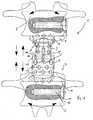
- eine Seitenansicht eines in die durch das Entfernen eines Wirbelkörpers entstandene Lücke zwischen zwei verbliebenen Wirbelkörpern eingesetzten Implantats,
- Fig. 2
- eine der
Figur 1Figur 1 - Fig. 3
- eine der
Figur 2 - Fig. 4
- eine der
Figur 2Figur 3
- Fig. 1
- a side view of an implant inserted into the gap created by the removal of a vertebral body between two remaining vertebral bodies,
- Fig. 2
- one of the
FIG. 1 corresponding representation without the for a better overview inFIG. 1 illustrated vertebral bodies, - Fig. 3
- one of the
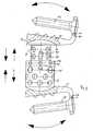
FIG. 2 corresponding representation with a made from the neutral position deflection, and - Fig. 4
- one of the
FIG. 2 corresponding representation with one oppositeFIG. 3 in the other direction made deflection.
In der Zeichnung ist ein Implantat 1 dargestellt, das zum Einsetzen zwischen zwei Wirbelkörper 2 der Wirbelsäule dient als Platzhalter für aus der Wirbelsäule entfernte Bandscheiben und Wirbel oder Wirbelteile, wobei dieses erfindungsgemäße Implantat 1 auch dann Verwendung finden kann, wenn ein Wirbelkörper 2 nicht vollständig aus der Wirbelsäule entfernt worden ist, sondern beispielsweise die Kleinwirbel-Gelenke 3 zum Verbleiben in der Wirbelsäule gerettet werden konnten. Dieses Implantat 1 umfasst zwei Implantatteile 4, die in Richtung ihrer koaxialen Längsachse 5 zur Längenänderung des Implantats 1 gegeneinander verstellbar sind, also durch die Längenänderung eine Distraktionsmöglichkeit während der Operation geschaffen ist, um die Länge des Implantats 1 auf die individuellen Erfordernisse einstellen zu können.In the drawing, an
Die Zeichnung lässt erkennen, dass das Implantat 1 eine an dem oberen Wirbelkörper 2 befestigbare Lagerplatte 5 mit einem gekrümmten Lagersitz 6 aufweist, an dem das in der Zeichnung obere Implantatteil 4 mit einer korrespondierend gekrümmten Lagerfläche 7 anliegt. Vergleichbar ist die Abstützung des Implantats 1 gegenüber dem in der Zeichnung unteren Wirbelkörper 2 realisiert, so dass die Lagerplatte 5 insgesamt zweifach vorgesehen ist zur Befestigung einer der Lagerplatten 5 in jedem der Wirbelkörper 2. Dabei sind die Lagersitze 6 konkav und die Lagerflächen 7 konvex gekrümmt mit einem übereinstimmenden Krümmungsradius der Lagerflächen 7 der beiden Implantatteile 4. Diese beiden Aussparungen 17 aufweisenden Implantatteile 4 realisieren damit ein Drehgelenk mit einem zwischen den beiden Lagerflächen 7 liegenden Drehpunkt, wobei aufgrund der geeigneten Gestaltung die Drehachse selber nicht fest vorgegeben ist, so dass das erfindungsgemäße Implantat Drehungen in verschiedenen Richtungen zulässt. Bemerkenswert ist dabei, wie in den
Der Zeichnung ist weiterhin zu entnehmen, dass die Lagerplatte 5 auf der am Wirbelkörper 2 zur Anlage kommenden Seite eine Mehrzahl eine Schneide 8 aufweisende Rastzähne 9 besitzt, die auf dem Umfang eines Kreises angeordnet sind. Diese Rastzähne 9 dienen der sicheren Verankerung der Lagerplatte 5 an dem Wirbelkörper 2 und vermeiden insbesondere eine gleitende Verschiebung der Lagerplatte 5 gegenüber der Wirbelkörperoberfläche. Zur Sicherung der Lagerplatte 5 gegenüber dem Wirbelkörper 2 ist weiterhin auf der vom Lagersitz 6 wegweisenden Seite zum lateralen Übergreifen des Wirbelkörpers 2 ein Plattensteg 10 ausgebildet, der eine Öffnung 11 aufweist, die von einer Knochenschraube 12 durchsetzt wird, die in den Wirbelkörper 2 eingreift.The drawing can also be seen that the
Die Zeichnung läßt weiterhin erkennen, dass die beiden Implantatteile 4 hülsenartig gestaltet und über ein Innengewinde und ein Außengewinde miteinander verbunden sind, wobei als Träger des Innengewindes ein mittleres Implantatteil 13 genutzt ist, dass mit einer der Hülsen gewindemäßig verbunden ist. Dabei greifen die beiden Implantatteile 4 axial ineinander und sind axial gegeneinander verschieblich geführt und gegen gegenseitiges Verdrehen um die Hülsenachse gesichert, wobei diese Sicherung in einfacher Weise erzielt wird, indem in einem Längsschlitz 14 einen Stift 15 eingreift. Zur Längenverstellung des Implantats 1 wird also das mittlere Implantatteil 13 mittels über den Umfang verteilt angeordneter Schlüsselöffnungen 16 verdreht, so dass die gewindemäßig mit dem mittleren Implantatteil 13 verbundene Hülse in dem mittleren Implantatteil 13 spindel und sich gegenüber dem anderen Implantatteil 4 verstellt. Nach Erreichen der gewünschten Distraktion wird durch eine Sicherungsschraube die relative axiale Lage des einen Implantatteils 4 gegenüber dem anderen Implantatteil 4 festgelegt, indem die Sicherungsschraube durch eine im Überlappungsbereich der einen Hülse mit der anderen Hülse platzierte Gewindebohrung geführt wird.The drawing also shows that the two
Claims (12)
- An implant for insertion between two vertebrae (2) of the spinal column as a place holder for vertebrae or vertebra portions and discs removed from the spinal column, comprising two implant portions (4) which are displaceable relative to each other in the direction of their coaxial longitudinal axes (5) for altering the length of the implant (1), wherein there is provided a mounting plate (5) which can be secured to one of the vertebrae (2) and has a curved mounting seat (6) against which one of the implant portions (4) bears with a correspondingly curved mounting surface (7), wherein the mounting plate (5) has at least one latching tooth (9) at the side coming to bear against the vertebra (2), wherein the latching tooth (9) has a cutting edge (8) and is provided in a multiple array,characterised in that the latching teeth (9) are arranged on a circle, the mounting plate (5) has a plate leg (10) on the side facing away from the mounting seat (6) for laterally engaging over the vertebra (2) and there is provided at least one bone screw (12) for securing the plate leg (10) which has at least one opening (11) to the vertebra (2).
- An implant according to claim 1characterised in that there are provided two mounting plates (15) for fixing one of the mounting plates (5) to each of the vertebrae (2) and each of the implant portions (4) has a mounting surface (7) curved corresponding to the associated mounting seat (6).
- An implant according to claim 1 or claim 2characterised in that the mounting seat (6) is concavely curved and the mounting surface (7) is convexly curved.
- An implant according to claim 2 or claim 3characterised in that the radius of curvature of the bearing surface (7) of the two implant portions (4) is the same.
- An implant according to one of claims 1 to 4characterised in that the two implant portions are of a sleeve-like configuration and are connected together by way of a female screwthread and a male screwthread.
- An implant according to one of claims 1 to 4characterised in that the two implant portions (4) are in the form of sleeves which engage axially into each other, which are guided displaceably axially relative to each other and are secured against rotation relative to each other about the sleeve axis, there is provided a central implant portion (13) having a female screwthread, and one of the sleeves is threadedly connected to the central implant portion (13) and has both the central implant portion (13) and also the other sleeve engaging thereover.
- An implant according to claim 5 or claim 6characterised in that the sleeves have apertures (17).
- An implant according to claim 6 or claim 7characterised in that the central implant portion (13) has wrench openings (16) arranged distributed uniformly over the periphery.
- An implant according to one of claims 6 to 8characterised in that one of the sleeves in the overlap region with the other sleeve has a screwthreaded bore for receiving a securing screw.
- An implant according to one of claims 1 to 9characterised in that the implant portions (4) and/or the mounting plates (5) are formed from titanium or steel or PEEK.
- An implant according to one of claims 1 to 11characterised in that the mounting plate (5) is variable and fixable in its longitudinal extent.
- An implant according to claim 11characterised in that the mounting plate (5) is divided outside the mounting seat (6) with mutually displaceable components.
Applications Claiming Priority (1)
| Application Number | Priority Date | Filing Date | Title |
|---|---|---|---|
| DE102006030124ADE102006030124A1 (en) | 2006-06-28 | 2006-06-28 | Implant for insertion between two vertebral bodies of the spine |
Publications (2)
| Publication Number | Publication Date |
|---|---|
| EP1872748A1 EP1872748A1 (en) | 2008-01-02 |
| EP1872748B1true EP1872748B1 (en) | 2009-12-23 |
Family
ID=38462531
Family Applications (1)
| Application Number | Title | Priority Date | Filing Date |
|---|---|---|---|
| EP07005220ANot-in-forceEP1872748B1 (en) | 2006-06-28 | 2007-03-14 | Implant for inserting between two vertebrae of the spine |
Country Status (4)
| Country | Link |
|---|---|
| US (1) | US8070817B2 (en) |
| EP (1) | EP1872748B1 (en) |
| AT (1) | ATE452604T1 (en) |
| DE (2) | DE102006030124A1 (en) |
Families Citing this family (53)
| Publication number | Priority date | Publication date | Assignee | Title |
|---|---|---|---|---|
| US7914562B2 (en)* | 2006-02-27 | 2011-03-29 | Zielinski Steven C | Method and apparatus for lateral reduction and fusion of the spine |
| US9237954B2 (en) | 2007-03-29 | 2016-01-19 | Life Spine, Inc. | Height adjustable spinal prostheses |
| US8940019B2 (en) | 2007-12-28 | 2015-01-27 | Osteomed Spine, Inc. | Bone tissue fixation device and method |
| US7909874B2 (en)* | 2008-01-30 | 2011-03-22 | Zielinski Steven C | Artificial spinal disk |
| US20110202135A1 (en)* | 2008-03-24 | 2011-08-18 | Lanx, Inc. | Expandable spinal interbody cage and methods |
| DE102008028589A1 (en) | 2008-06-18 | 2009-12-24 | Rüger, Florian | Implant for insertion between vertebral bodies of the spine |
| DE102008042401A1 (en) | 2008-09-26 | 2010-04-08 | Forschungszentrum Karlsruhe Gmbh | Intervertebral disk implant for use between vertebras of spinal column of humans and vertebrate animals, has support component comprising flexible core and biocompatible matrix layer, which is formed with tissue cells |
| US8636772B2 (en) | 2009-06-23 | 2014-01-28 | Osteomed Llc | Bone plates, screws, and instruments |
| EP2445428A2 (en) | 2009-06-23 | 2012-05-02 | Osteomed Spine, Inc. | Bone tissue clamp |
| CN101627931B (en)* | 2009-08-06 | 2010-12-01 | 雷伟 | A kind of artificial cervical compound joint |
| BR112012003050A2 (en) | 2009-08-10 | 2019-09-24 | Osteomed Llc | bone plate assembly, bone surface attachment plate, cushion and bone plate |
| DE102010004275A1 (en)* | 2010-01-11 | 2011-07-21 | Metz-Stavenhagen, Peter, Dr. med., 34537 | Vertebral body spacer |
| US10596004B2 (en)* | 2010-01-13 | 2020-03-24 | Jcbd, Llc | Spinopelvic fixation technology |
| US8870880B2 (en) | 2010-04-12 | 2014-10-28 | Globus Medical, Inc. | Angling inserter tool for expandable vertebral implant |
| US9579211B2 (en) | 2010-04-12 | 2017-02-28 | Globus Medical, Inc. | Expandable vertebral implant |
| US11426287B2 (en) | 2010-04-12 | 2022-08-30 | Globus Medical Inc. | Expandable vertebral implant |
| US9301850B2 (en) | 2010-04-12 | 2016-04-05 | Globus Medical, Inc. | Expandable vertebral implant |
| US8591585B2 (en) | 2010-04-12 | 2013-11-26 | Globus Medical, Inc. | Expandable vertebral implant |
| US9066814B2 (en) | 2010-08-02 | 2015-06-30 | Ulrich Medical Usa, Inc. | Implant assembly having an angled head |
| US9474625B2 (en)* | 2010-09-03 | 2016-10-25 | Globus Medical, Inc | Expandable fusion device and method of installation thereof |
| US8377140B2 (en) | 2011-01-12 | 2013-02-19 | Ebi, Llc | Expandable spinal implant device |
| US9700425B1 (en) | 2011-03-20 | 2017-07-11 | Nuvasive, Inc. | Vertebral body replacement and insertion methods |
| US9452062B2 (en)* | 2011-06-29 | 2016-09-27 | Xijing He | Adjustable complex of artificial cervical vertebra and intervertebral connector |
| US8945228B2 (en) | 2012-11-15 | 2015-02-03 | DePuy Synthes Products, LLC | Endplate for a vertebral implant |
| US9138324B2 (en)* | 2013-01-24 | 2015-09-22 | Warsaw Orthopedic, Inc. | Expandable spinal implant system and method |
| US10426632B2 (en) | 2013-03-13 | 2019-10-01 | Life Spine, Inc. | Expandable spinal interbody assembly |
| US12193948B2 (en) | 2013-03-13 | 2025-01-14 | Life Spine, Inc. | Expandable implant assembly |
| WO2014145766A1 (en)* | 2013-03-15 | 2014-09-18 | Paradigm Spine, Llc | Modular, customizable spine stabilization system |
| US9968460B2 (en) | 2013-03-15 | 2018-05-15 | Medsmart Innovation Inc. | Dynamic spinal segment replacement |
| US9566167B2 (en) | 2013-08-22 | 2017-02-14 | K2M, Inc. | Expandable spinal implant |
| US9211193B2 (en) | 2013-08-30 | 2015-12-15 | Aesculap Implant Systems, Llc | Prosthesis, system and method |
| AU2015269383B2 (en) | 2014-06-04 | 2017-12-07 | Wenzel Spine, Inc. | Bilaterally expanding intervertebral body fusion device |
| US10363142B2 (en) | 2014-12-11 | 2019-07-30 | K2M, Inc. | Expandable spinal implants |
| US20160354161A1 (en) | 2015-06-05 | 2016-12-08 | Ortho Kinematics, Inc. | Methods for data processing for intra-operative navigation systems |
| CN105055008A (en)* | 2015-09-07 | 2015-11-18 | 徐嘉炜 | Anterior screw plate device capable of being lengthened |
| US20180353302A1 (en)* | 2015-09-18 | 2018-12-13 | The Board Of Trustees Of The University Of Illinoi | Adjustable, Implantable Spinal Disc Device for Deformity Correction in Intervertebral Fusion Procedures |
| CN105853031B (en)* | 2016-04-29 | 2017-10-03 | 西安交通大学第二附属医院 | A kind of bionical anti-artificial lumbar vertebrae of dislocation and interverbebral disc junctional complex |
| US10537434B2 (en)* | 2016-08-08 | 2020-01-21 | Wu Jau Ching | Intervertebral implant |
| US11707203B2 (en) | 2016-10-11 | 2023-07-25 | Wenzel Spine, Inc. | Systems for generating image-based measurements during diagnosis |
| US11896494B2 (en) | 2017-07-10 | 2024-02-13 | Life Spine, Inc. | Expandable implant assembly |
| US10441430B2 (en) | 2017-07-24 | 2019-10-15 | K2M, Inc. | Expandable spinal implants |
| US10603055B2 (en) | 2017-09-15 | 2020-03-31 | Jcbd, Llc | Systems for and methods of preparing and fusing a sacroiliac joint |
| US11219532B2 (en)* | 2017-09-18 | 2022-01-11 | Loubert S. Suddaby | Stand-alone expandable interbody spinal fusion device with locking mechanism |
| US10744003B2 (en)* | 2018-05-08 | 2020-08-18 | Globus Medical, Inc. | Intervertebral spinal implant |
| CN109758273A (en)* | 2019-02-28 | 2019-05-17 | 河南省人民医院 | An adjustable self-stabilizing lumbosacral artificial vertebral body |
| US11382764B2 (en) | 2019-06-10 | 2022-07-12 | Life Spine, Inc. | Expandable implant assembly with compression features |
| US12042395B2 (en) | 2019-06-11 | 2024-07-23 | Life Spine, Inc. | Expandable implant assembly |
| US11857432B2 (en) | 2020-04-13 | 2024-01-02 | Life Spine, Inc. | Expandable implant assembly |
| US11602439B2 (en) | 2020-04-16 | 2023-03-14 | Life Spine, Inc. | Expandable implant assembly |
| US12336917B2 (en) | 2020-05-15 | 2025-06-24 | Life Spine, Inc. | Steerable implant assembly |
| US11602440B2 (en) | 2020-06-25 | 2023-03-14 | Life Spine, Inc. | Expandable implant assembly |
| US11554020B2 (en) | 2020-09-08 | 2023-01-17 | Life Spine, Inc. | Expandable implant with pivoting control assembly |
| CN113208785B (en)* | 2021-06-10 | 2022-04-19 | 北京爱康宜诚医疗器材有限公司 | Vertebral prosthesis |
Family Cites Families (24)
| Publication number | Priority date | Publication date | Assignee | Title |
|---|---|---|---|---|
| US5236460A (en)* | 1990-02-12 | 1993-08-17 | Midas Rex Pneumatic Tools, Inc. | Vertebral body prosthesis |
| US5425773A (en) | 1992-01-06 | 1995-06-20 | Danek Medical, Inc. | Intervertebral disk arthroplasty device |
| US5258031A (en)* | 1992-01-06 | 1993-11-02 | Danek Medical | Intervertebral disk arthroplasty |
| JPH06178787A (en)* | 1992-12-14 | 1994-06-28 | Shima Yumiko | Centrum spacer with joint, intervertebral cavity measuring device and centrum spacer pattern |
| US5360430A (en)* | 1993-07-29 | 1994-11-01 | Lin Chih I | Intervertebral locking device |
| DE19622827B4 (en)* | 1996-06-07 | 2009-04-23 | Ulrich, Heinrich | Implant for insertion between vertebrae as a placeholder |
| US5702455A (en)* | 1996-07-03 | 1997-12-30 | Saggar; Rahul | Expandable prosthesis for spinal fusion |
| DE29616778U1 (en)* | 1996-09-26 | 1998-01-29 | Howmedica GmbH, 24232 Schönkirchen | Vertebral body placeholder |
| US5916267A (en)* | 1997-04-07 | 1999-06-29 | Arthit Sitiso | Anterior spinal implant system for vertebral body prosthesis |
| AU723279B2 (en)* | 1997-04-15 | 2000-08-24 | Synthes Gmbh | Telescopic vertebral prosthesis |
| FR2774280B1 (en)* | 1998-01-30 | 2000-07-28 | Dimso Sa | IMPLANT TO REPLACE A VERTEBRA |
| DE19804765C2 (en) | 1998-02-06 | 2000-09-28 | Biedermann Motech Gmbh | Placeholder with adjustable axial length |
| DE19816782A1 (en)* | 1998-04-16 | 1999-10-28 | Ulrich Gmbh & Co Kg | Implant for insertion between the vertebral body of the spine |
| DE19856013A1 (en) | 1998-12-04 | 2000-06-08 | Wittenstein Gmbh & Co Kg | Distraction device |
| US6866682B1 (en) | 1999-09-02 | 2005-03-15 | Stryker Spine | Distractable corpectomy device |
| DE10138079B4 (en)* | 2001-08-03 | 2004-02-12 | Biedermann Motech Gmbh | Placeholder with variable axial length |
| TW545211U (en)* | 2001-08-29 | 2003-08-01 | Jung-Chiuan Ye | Device for fastening spine |
| DE10242331B4 (en) | 2002-09-12 | 2005-10-20 | Biedermann Motech Gmbh | Placeholder for vertebral bodies or intervertebral discs |
| US20040167626A1 (en)* | 2003-01-23 | 2004-08-26 | Geremakis Perry A. | Expandable artificial disc prosthesis |
| DE10311477A1 (en)* | 2003-03-15 | 2004-09-23 | Ulrich Gmbh & Co. Kg | Implant to be inserted between the vertebral body of the spine |
| DE10324108B3 (en)* | 2003-05-21 | 2005-01-27 | Aesculap Ag & Co. Kg | Backbone implant is inserted with contracted contact disc which is expanded to optimum area following insertion |
| US7255714B2 (en)* | 2003-09-30 | 2007-08-14 | Michel H. Malek | Vertically adjustable intervertebral disc prosthesis |
| US20050256576A1 (en) | 2004-05-13 | 2005-11-17 | Moskowitz Nathan C | Artificial expansile total lumbar and thoracic discs for posterior placement without supplemental instrumentation and its adaptation for anterior placement of artificial cervical, thoracic and lumbar discs |
| MXPA06014714A (en)* | 2004-06-30 | 2007-06-22 | Synergy Disc Replacement Inc | Artificial spinal disc. |
- 2006
- 2006-06-28DEDE102006030124Apatent/DE102006030124A1/ennot_activeWithdrawn
- 2007
- 2007-03-14DEDE502007002378Tpatent/DE502007002378D1/enactiveActive
- 2007-03-14ATAT07005220Tpatent/ATE452604T1/enactive
- 2007-03-14EPEP07005220Apatent/EP1872748B1/ennot_activeNot-in-force
- 2007-06-27USUS11/823,467patent/US8070817B2/ennot_activeExpired - Fee Related
Also Published As
| Publication number | Publication date |
|---|---|
| EP1872748A1 (en) | 2008-01-02 |
| ATE452604T1 (en) | 2010-01-15 |
| US20080015704A1 (en) | 2008-01-17 |
| US8070817B2 (en) | 2011-12-06 |
| DE102006030124A1 (en) | 2008-01-03 |
| DE502007002378D1 (en) | 2010-02-04 |
Similar Documents
| Publication | Publication Date | Title |
|---|---|---|
| EP1872748B1 (en) | Implant for inserting between two vertebrae of the spine | |
| EP2826446B1 (en) | Operating tool for an implant | |
| EP1274354B1 (en) | Device for the articulated connection of two bodies | |
| EP1481654B1 (en) | Intervertebral fusion implant and instrument for placement and distraction of said implant | |
| EP1030605B1 (en) | Operative system to correct vertebral body splitting | |
| EP1180979B1 (en) | Bone fixation device with a rotation joint | |
| EP1575457B1 (en) | Intervertebral implant | |
| EP2777629B1 (en) | Spreadable implant for the spinal column. | |
| EP1572037B1 (en) | Intervertebral implant with tiltable joint parts | |
| EP1615598B1 (en) | Spondylodesis device | |
| EP0452451B1 (en) | Pedicle screw, and correction and retaining device with said pedicle screw | |
| EP1792588B1 (en) | Insert instrument for an implant between vertebrae | |
| DE19580181B4 (en) | Positioning and support device for spinal column - has shear lift bar with operating screw between support plates for support and has tool extension on side support member | |
| EP1121075B1 (en) | Telescopic vertebral prosthesis | |
| EP1572038B1 (en) | Intervertebral implant comprising joint parts that are mounted to form a universal joint | |
| EP1620023B1 (en) | Dynamic anchoring device and dynamic stabilizing device, which serves to stabilize bones, particularly vertebrae, and which has an anchoring device of this type | |
| EP0671151A1 (en) | Osteosynthetic device | |
| DE10323363A1 (en) | Implant for insertion between elements of the vertebral column comprises a hinge which consist of a socket plate and a head element, and is located between the hinge cover plates | |
| WO1998007392A1 (en) | Endoprosthesis | |
| EP2645950B1 (en) | Fusion implant for facet joints | |
| EP2861187B1 (en) | Intervertebral fusion implant | |
| EP2499999B1 (en) | Spinal implant with rings | |
| EP2992859A1 (en) | Continuously adjustable intervertebral implant | |
| EP1491165A1 (en) | Vertebral prosthesis | |
| WO2006086895A1 (en) | Intervertebral implant |
Legal Events
| Date | Code | Title | Description |
|---|---|---|---|
| PUAI | Public reference made under article 153(3) epc to a published international application that has entered the european phase | Free format text:ORIGINAL CODE: 0009012 | |
| AK | Designated contracting states | Kind code of ref document:A1 Designated state(s):AT BE BG CH CY CZ DE DK EE ES FI FR GB GR HU IE IS IT LI LT LU LV MC MT NL PL PT RO SE SI SK TR | |
| AX | Request for extension of the european patent | Extension state:AL BA HR MK YU | |
| RAP1 | Party data changed (applicant data changed or rights of an application transferred) | Owner name:M.O.R.E. MEDICAL SOLUTIONS GMBH | |
| 17P | Request for examination filed | Effective date:20080603 | |
| 17Q | First examination report despatched | Effective date:20080707 | |
| AKX | Designation fees paid | Designated state(s):AT BE BG CH CY CZ DE DK EE ES FI FR GB GR HU IE IS IT LI LT LU LV MC MT NL PL PT RO SE SI SK TR | |
| GRAP | Despatch of communication of intention to grant a patent | Free format text:ORIGINAL CODE: EPIDOSNIGR1 | |
| GRAS | Grant fee paid | Free format text:ORIGINAL CODE: EPIDOSNIGR3 | |
| GRAA | (expected) grant | Free format text:ORIGINAL CODE: 0009210 | |
| AK | Designated contracting states | Kind code of ref document:B1 Designated state(s):AT BE BG CH CY CZ DE DK EE ES FI FR GB GR HU IE IS IT LI LT LU LV MC MT NL PL PT RO SE SI SK TR | |
| REG | Reference to a national code | Ref country code:GB Ref legal event code:FG4D Free format text:NOT ENGLISH | |
| REG | Reference to a national code | Ref country code:CH Ref legal event code:EP | |
| REG | Reference to a national code | Ref country code:IE Ref legal event code:FG4D | |
| REF | Corresponds to: | Ref document number:502007002378 Country of ref document:DE Date of ref document:20100204 Kind code of ref document:P | |
| REG | Reference to a national code | Ref country code:NL Ref legal event code:VDEP Effective date:20091223 | |
| PG25 | Lapsed in a contracting state [announced via postgrant information from national office to epo] | Ref country code:FI Free format text:LAPSE BECAUSE OF FAILURE TO SUBMIT A TRANSLATION OF THE DESCRIPTION OR TO PAY THE FEE WITHIN THE PRESCRIBED TIME-LIMIT Effective date:20091223 Ref country code:SE Free format text:LAPSE BECAUSE OF FAILURE TO SUBMIT A TRANSLATION OF THE DESCRIPTION OR TO PAY THE FEE WITHIN THE PRESCRIBED TIME-LIMIT Effective date:20091223 Ref country code:LT Free format text:LAPSE BECAUSE OF FAILURE TO SUBMIT A TRANSLATION OF THE DESCRIPTION OR TO PAY THE FEE WITHIN THE PRESCRIBED TIME-LIMIT Effective date:20091223 | |
| LTIE | Lt: invalidation of european patent or patent extension | Effective date:20091223 | |
| PG25 | Lapsed in a contracting state [announced via postgrant information from national office to epo] | Ref country code:SI Free format text:LAPSE BECAUSE OF FAILURE TO SUBMIT A TRANSLATION OF THE DESCRIPTION OR TO PAY THE FEE WITHIN THE PRESCRIBED TIME-LIMIT Effective date:20091223 Ref country code:PL Free format text:LAPSE BECAUSE OF FAILURE TO SUBMIT A TRANSLATION OF THE DESCRIPTION OR TO PAY THE FEE WITHIN THE PRESCRIBED TIME-LIMIT Effective date:20091223 Ref country code:LV Free format text:LAPSE BECAUSE OF FAILURE TO SUBMIT A TRANSLATION OF THE DESCRIPTION OR TO PAY THE FEE WITHIN THE PRESCRIBED TIME-LIMIT Effective date:20091223 | |
| REG | Reference to a national code | Ref country code:IE Ref legal event code:FD4D | |
| PG25 | Lapsed in a contracting state [announced via postgrant information from national office to epo] | Ref country code:EE Free format text:LAPSE BECAUSE OF FAILURE TO SUBMIT A TRANSLATION OF THE DESCRIPTION OR TO PAY THE FEE WITHIN THE PRESCRIBED TIME-LIMIT Effective date:20091223 Ref country code:BG Free format text:LAPSE BECAUSE OF FAILURE TO SUBMIT A TRANSLATION OF THE DESCRIPTION OR TO PAY THE FEE WITHIN THE PRESCRIBED TIME-LIMIT Effective date:20100323 Ref country code:PT Free format text:LAPSE BECAUSE OF FAILURE TO SUBMIT A TRANSLATION OF THE DESCRIPTION OR TO PAY THE FEE WITHIN THE PRESCRIBED TIME-LIMIT Effective date:20100423 Ref country code:ES Free format text:LAPSE BECAUSE OF FAILURE TO SUBMIT A TRANSLATION OF THE DESCRIPTION OR TO PAY THE FEE WITHIN THE PRESCRIBED TIME-LIMIT Effective date:20100403 Ref country code:RO Free format text:LAPSE BECAUSE OF FAILURE TO SUBMIT A TRANSLATION OF THE DESCRIPTION OR TO PAY THE FEE WITHIN THE PRESCRIBED TIME-LIMIT Effective date:20091223 Ref country code:NL Free format text:LAPSE BECAUSE OF FAILURE TO SUBMIT A TRANSLATION OF THE DESCRIPTION OR TO PAY THE FEE WITHIN THE PRESCRIBED TIME-LIMIT Effective date:20091223 Ref country code:IS Free format text:LAPSE BECAUSE OF FAILURE TO SUBMIT A TRANSLATION OF THE DESCRIPTION OR TO PAY THE FEE WITHIN THE PRESCRIBED TIME-LIMIT Effective date:20100423 | |
| PG25 | Lapsed in a contracting state [announced via postgrant information from national office to epo] | Ref country code:CZ Free format text:LAPSE BECAUSE OF FAILURE TO SUBMIT A TRANSLATION OF THE DESCRIPTION OR TO PAY THE FEE WITHIN THE PRESCRIBED TIME-LIMIT Effective date:20091223 Ref country code:SK Free format text:LAPSE BECAUSE OF FAILURE TO SUBMIT A TRANSLATION OF THE DESCRIPTION OR TO PAY THE FEE WITHIN THE PRESCRIBED TIME-LIMIT Effective date:20091223 | |
| BERE | Be: lapsed | Owner name:M.O.R.E. MEDICAL SOLUTIONS G.M.B.H. Effective date:20100331 | |
| PG25 | Lapsed in a contracting state [announced via postgrant information from national office to epo] | Ref country code:GR Free format text:LAPSE BECAUSE OF FAILURE TO SUBMIT A TRANSLATION OF THE DESCRIPTION OR TO PAY THE FEE WITHIN THE PRESCRIBED TIME-LIMIT Effective date:20100324 Ref country code:IE Free format text:LAPSE BECAUSE OF FAILURE TO SUBMIT A TRANSLATION OF THE DESCRIPTION OR TO PAY THE FEE WITHIN THE PRESCRIBED TIME-LIMIT Effective date:20091223 Ref country code:MC Free format text:LAPSE BECAUSE OF NON-PAYMENT OF DUE FEES Effective date:20100331 Ref country code:CY Free format text:LAPSE BECAUSE OF FAILURE TO SUBMIT A TRANSLATION OF THE DESCRIPTION OR TO PAY THE FEE WITHIN THE PRESCRIBED TIME-LIMIT Effective date:20091223 | |
| PLBE | No opposition filed within time limit | Free format text:ORIGINAL CODE: 0009261 | |
| STAA | Information on the status of an ep patent application or granted ep patent | Free format text:STATUS: NO OPPOSITION FILED WITHIN TIME LIMIT | |
| 26N | No opposition filed | Effective date:20100924 | |
| PG25 | Lapsed in a contracting state [announced via postgrant information from national office to epo] | Ref country code:DK Free format text:LAPSE BECAUSE OF FAILURE TO SUBMIT A TRANSLATION OF THE DESCRIPTION OR TO PAY THE FEE WITHIN THE PRESCRIBED TIME-LIMIT Effective date:20091223 | |
| PG25 | Lapsed in a contracting state [announced via postgrant information from national office to epo] | Ref country code:BE Free format text:LAPSE BECAUSE OF NON-PAYMENT OF DUE FEES Effective date:20100331 | |
| PG25 | Lapsed in a contracting state [announced via postgrant information from national office to epo] | Ref country code:IT Free format text:LAPSE BECAUSE OF FAILURE TO SUBMIT A TRANSLATION OF THE DESCRIPTION OR TO PAY THE FEE WITHIN THE PRESCRIBED TIME-LIMIT Effective date:20091223 | |
| PG25 | Lapsed in a contracting state [announced via postgrant information from national office to epo] | Ref country code:MT Free format text:LAPSE BECAUSE OF FAILURE TO SUBMIT A TRANSLATION OF THE DESCRIPTION OR TO PAY THE FEE WITHIN THE PRESCRIBED TIME-LIMIT Effective date:20091223 | |
| REG | Reference to a national code | Ref country code:CH Ref legal event code:PL | |
| PG25 | Lapsed in a contracting state [announced via postgrant information from national office to epo] | Ref country code:CH Free format text:LAPSE BECAUSE OF NON-PAYMENT OF DUE FEES Effective date:20110331 Ref country code:LI Free format text:LAPSE BECAUSE OF NON-PAYMENT OF DUE FEES Effective date:20110331 | |
| PG25 | Lapsed in a contracting state [announced via postgrant information from national office to epo] | Ref country code:LU Free format text:LAPSE BECAUSE OF NON-PAYMENT OF DUE FEES Effective date:20100314 Ref country code:HU Free format text:LAPSE BECAUSE OF FAILURE TO SUBMIT A TRANSLATION OF THE DESCRIPTION OR TO PAY THE FEE WITHIN THE PRESCRIBED TIME-LIMIT Effective date:20100624 | |
| PG25 | Lapsed in a contracting state [announced via postgrant information from national office to epo] | Ref country code:TR Free format text:LAPSE BECAUSE OF FAILURE TO SUBMIT A TRANSLATION OF THE DESCRIPTION OR TO PAY THE FEE WITHIN THE PRESCRIBED TIME-LIMIT Effective date:20091223 | |
| REG | Reference to a national code | Ref country code:AT Ref legal event code:MM01 Ref document number:452604 Country of ref document:AT Kind code of ref document:T Effective date:20120314 | |
| PG25 | Lapsed in a contracting state [announced via postgrant information from national office to epo] | Ref country code:AT Free format text:LAPSE BECAUSE OF NON-PAYMENT OF DUE FEES Effective date:20120314 | |
| REG | Reference to a national code | Ref country code:DE Ref legal event code:R082 Ref document number:502007002378 Country of ref document:DE Representative=s name:HENTRICH, SWEN, DIPL.-PHYS. DR.RER.NAT., DE | |
| PGFP | Annual fee paid to national office [announced via postgrant information from national office to epo] | Ref country code:DE Payment date:20140311 Year of fee payment:8 | |
| PGFP | Annual fee paid to national office [announced via postgrant information from national office to epo] | Ref country code:FR Payment date:20140319 Year of fee payment:8 | |
| PGFP | Annual fee paid to national office [announced via postgrant information from national office to epo] | Ref country code:GB Payment date:20140307 Year of fee payment:8 | |
| REG | Reference to a national code | Ref country code:DE Ref legal event code:R119 Ref document number:502007002378 Country of ref document:DE | |
| GBPC | Gb: european patent ceased through non-payment of renewal fee | Effective date:20150314 | |
| REG | Reference to a national code | Ref country code:FR Ref legal event code:ST Effective date:20151130 | |
| PG25 | Lapsed in a contracting state [announced via postgrant information from national office to epo] | Ref country code:GB Free format text:LAPSE BECAUSE OF NON-PAYMENT OF DUE FEES Effective date:20150314 Ref country code:DE Free format text:LAPSE BECAUSE OF NON-PAYMENT OF DUE FEES Effective date:20151001 | |
| PG25 | Lapsed in a contracting state [announced via postgrant information from national office to epo] | Ref country code:FR Free format text:LAPSE BECAUSE OF NON-PAYMENT OF DUE FEES Effective date:20150331 |