EP1872743A1 - Cardiovascular valve assembly with resizable docking station - Google Patents
Cardiovascular valve assembly with resizable docking stationDownload PDFInfo
- Publication number
- EP1872743A1 EP1872743A1EP07111254AEP07111254AEP1872743A1EP 1872743 A1EP1872743 A1EP 1872743A1EP 07111254 AEP07111254 AEP 07111254AEP 07111254 AEP07111254 AEP 07111254AEP 1872743 A1EP1872743 A1EP 1872743A1
- Authority
- EP
- European Patent Office
- Prior art keywords
- valve
- tubular body
- valve assembly
- base member
- assembly according
- Prior art date
- Legal status (The legal status is an assumption and is not a legal conclusion. Google has not performed a legal analysis and makes no representation as to the accuracy of the status listed.)
- Granted
Links
- 230000002526effect on cardiovascular systemEffects0.000titleabstractdescription13
- 238000003032molecular dockingMethods0.000titledescription2
- 230000008878couplingEffects0.000claimsdescription19
- 238000010168coupling processMethods0.000claimsdescription19
- 238000005859coupling reactionMethods0.000claimsdescription19
- 239000000463materialSubstances0.000description6
- 230000008901benefitEffects0.000description4
- 238000009434installationMethods0.000description3
- RTAQQCXQSZGOHL-UHFFFAOYSA-NTitaniumChemical compound[Ti]RTAQQCXQSZGOHL-UHFFFAOYSA-N0.000description2
- 230000004075alterationEffects0.000description2
- 230000000916dilatatory effectEffects0.000description2
- PCHJSUWPFVWCPO-UHFFFAOYSA-NgoldChemical compound[Au]PCHJSUWPFVWCPO-UHFFFAOYSA-N0.000description2
- 229910052737goldInorganic materials0.000description2
- 239000010931goldSubstances0.000description2
- 229910052751metalInorganic materials0.000description2
- 239000002184metalSubstances0.000description2
- 238000000034methodMethods0.000description2
- 238000012986modificationMethods0.000description2
- 230000004048modificationEffects0.000description2
- BASFCYQUMIYNBI-UHFFFAOYSA-NplatinumChemical compound[Pt]BASFCYQUMIYNBI-UHFFFAOYSA-N0.000description2
- 229910001220stainless steelInorganic materials0.000description2
- 239000010935stainless steelSubstances0.000description2
- 238000001356surgical procedureMethods0.000description2
- 229910052719titaniumInorganic materials0.000description2
- 239000010936titaniumSubstances0.000description2
- 0*[C@](C1)(C1IC1)C11C=CC1Chemical compound*[C@](C1)(C1IC1)C11C=CC10.000description1
- 238000004026adhesive bondingMethods0.000description1
- 230000003466anti-cipated effectEffects0.000description1
- 230000000712assemblyEffects0.000description1
- 238000000429assemblyMethods0.000description1
- 239000000109continuous materialSubstances0.000description1
- 230000001419dependent effectEffects0.000description1
- 230000010339dilationEffects0.000description1
- 238000002594fluoroscopyMethods0.000description1
- 238000002513implantationMethods0.000description1
- 238000003780insertionMethods0.000description1
- 230000037431insertionEffects0.000description1
- 238000004519manufacturing processMethods0.000description1
- 150000002739metalsChemical class0.000description1
- 238000002324minimally invasive surgeryMethods0.000description1
- 229910001000nickel titaniumInorganic materials0.000description1
- HLXZNVUGXRDIFK-UHFFFAOYSA-Nnickel titaniumChemical compound[Ti].[Ti].[Ti].[Ti].[Ti].[Ti].[Ti].[Ti].[Ti].[Ti].[Ti].[Ni].[Ni].[Ni].[Ni].[Ni].[Ni].[Ni].[Ni].[Ni].[Ni].[Ni].[Ni].[Ni].[Ni]HLXZNVUGXRDIFK-UHFFFAOYSA-N0.000description1
- 230000000737periodic effectEffects0.000description1
- 229910052697platinumInorganic materials0.000description1
- 210000001147pulmonary arteryAnatomy0.000description1
- 208000009138pulmonary valve stenosisDiseases0.000description1
- 208000030390pulmonic stenosisDiseases0.000description1
- 229910052709silverInorganic materials0.000description1
- 239000004332silverSubstances0.000description1
- 238000004513sizingMethods0.000description1
- 238000005476solderingMethods0.000description1
- 229910052715tantalumInorganic materials0.000description1
- GUVRBAGPIYLISA-UHFFFAOYSA-Ntantalum atomChemical compound[Ta]GUVRBAGPIYLISA-UHFFFAOYSA-N0.000description1
- 238000003466weldingMethods0.000description1
Images


Classifications
- A—HUMAN NECESSITIES
- A61—MEDICAL OR VETERINARY SCIENCE; HYGIENE
- A61F—FILTERS IMPLANTABLE INTO BLOOD VESSELS; PROSTHESES; DEVICES PROVIDING PATENCY TO, OR PREVENTING COLLAPSING OF, TUBULAR STRUCTURES OF THE BODY, e.g. STENTS; ORTHOPAEDIC, NURSING OR CONTRACEPTIVE DEVICES; FOMENTATION; TREATMENT OR PROTECTION OF EYES OR EARS; BANDAGES, DRESSINGS OR ABSORBENT PADS; FIRST-AID KITS
- A61F2/00—Filters implantable into blood vessels; Prostheses, i.e. artificial substitutes or replacements for parts of the body; Appliances for connecting them with the body; Devices providing patency to, or preventing collapsing of, tubular structures of the body, e.g. stents
- A61F2/02—Prostheses implantable into the body
- A61F2/24—Heart valves ; Vascular valves, e.g. venous valves; Heart implants, e.g. passive devices for improving the function of the native valve or the heart muscle; Transmyocardial revascularisation [TMR] devices; Valves implantable in the body
- A61F2/2412—Heart valves ; Vascular valves, e.g. venous valves; Heart implants, e.g. passive devices for improving the function of the native valve or the heart muscle; Transmyocardial revascularisation [TMR] devices; Valves implantable in the body with soft flexible valve members, e.g. tissue valves shaped like natural valves
- A61F2/2418—Scaffolds therefor, e.g. support stents
- A—HUMAN NECESSITIES
- A61—MEDICAL OR VETERINARY SCIENCE; HYGIENE
- A61F—FILTERS IMPLANTABLE INTO BLOOD VESSELS; PROSTHESES; DEVICES PROVIDING PATENCY TO, OR PREVENTING COLLAPSING OF, TUBULAR STRUCTURES OF THE BODY, e.g. STENTS; ORTHOPAEDIC, NURSING OR CONTRACEPTIVE DEVICES; FOMENTATION; TREATMENT OR PROTECTION OF EYES OR EARS; BANDAGES, DRESSINGS OR ABSORBENT PADS; FIRST-AID KITS
- A61F2230/00—Geometry of prostheses classified in groups A61F2/00 - A61F2/26 or A61F2/82 or A61F9/00 or A61F11/00 or subgroups thereof
- A61F2230/0002—Two-dimensional shapes, e.g. cross-sections
- A61F2230/0028—Shapes in the form of latin or greek characters
- A61F2230/0054—V-shaped
- A—HUMAN NECESSITIES
- A61—MEDICAL OR VETERINARY SCIENCE; HYGIENE
- A61F—FILTERS IMPLANTABLE INTO BLOOD VESSELS; PROSTHESES; DEVICES PROVIDING PATENCY TO, OR PREVENTING COLLAPSING OF, TUBULAR STRUCTURES OF THE BODY, e.g. STENTS; ORTHOPAEDIC, NURSING OR CONTRACEPTIVE DEVICES; FOMENTATION; TREATMENT OR PROTECTION OF EYES OR EARS; BANDAGES, DRESSINGS OR ABSORBENT PADS; FIRST-AID KITS
- A61F2250/00—Special features of prostheses classified in groups A61F2/00 - A61F2/26 or A61F2/82 or A61F9/00 or A61F11/00 or subgroups thereof
- A61F2250/0004—Special features of prostheses classified in groups A61F2/00 - A61F2/26 or A61F2/82 or A61F9/00 or A61F11/00 or subgroups thereof adjustable
- A61F2250/001—Special features of prostheses classified in groups A61F2/00 - A61F2/26 or A61F2/82 or A61F9/00 or A61F11/00 or subgroups thereof adjustable for adjusting a diameter
- A—HUMAN NECESSITIES
- A61—MEDICAL OR VETERINARY SCIENCE; HYGIENE
- A61F—FILTERS IMPLANTABLE INTO BLOOD VESSELS; PROSTHESES; DEVICES PROVIDING PATENCY TO, OR PREVENTING COLLAPSING OF, TUBULAR STRUCTURES OF THE BODY, e.g. STENTS; ORTHOPAEDIC, NURSING OR CONTRACEPTIVE DEVICES; FOMENTATION; TREATMENT OR PROTECTION OF EYES OR EARS; BANDAGES, DRESSINGS OR ABSORBENT PADS; FIRST-AID KITS
- A61F2250/00—Special features of prostheses classified in groups A61F2/00 - A61F2/26 or A61F2/82 or A61F9/00 or A61F11/00 or subgroups thereof
- A61F2250/0058—Additional features; Implant or prostheses properties not otherwise provided for
- A61F2250/006—Additional features; Implant or prostheses properties not otherwise provided for modular
- A—HUMAN NECESSITIES
- A61—MEDICAL OR VETERINARY SCIENCE; HYGIENE
- A61F—FILTERS IMPLANTABLE INTO BLOOD VESSELS; PROSTHESES; DEVICES PROVIDING PATENCY TO, OR PREVENTING COLLAPSING OF, TUBULAR STRUCTURES OF THE BODY, e.g. STENTS; ORTHOPAEDIC, NURSING OR CONTRACEPTIVE DEVICES; FOMENTATION; TREATMENT OR PROTECTION OF EYES OR EARS; BANDAGES, DRESSINGS OR ABSORBENT PADS; FIRST-AID KITS
- A61F2250/00—Special features of prostheses classified in groups A61F2/00 - A61F2/26 or A61F2/82 or A61F9/00 or A61F11/00 or subgroups thereof
- A61F2250/0058—Additional features; Implant or prostheses properties not otherwise provided for
- A61F2250/0082—Additional features; Implant or prostheses properties not otherwise provided for specially designed for children, e.g. having means for adjusting to their growth
Definitions
- the present inventionrelates generally to a cardiovascular valve assembly, and more specifically relates to a cardiovascular valve assembly comprised of a resizable base member that remains in a patient, and a valve member that is detachably mountable to the resizable base member.
- a valve membermay require periodic replacement due to wear. Accordingly, the current valve member is detached from the permanent base member and a new valve member is mounted thereto. It may also be necessary to replace the current valve member because the patient has grown and requires a valve member having larger dimensions. In this regard, children need frequent valve member replacements as they grow to full adult size. However, existing base members have a fixed diameter, thus preventing a simple exchange of valve members with different dimensions.
- One purpose of the present inventionis to address the needs of a child patient who may have valve problems (e.g., pulmonary stenosis).
- valve problemse.g., pulmonary stenosis
- catheter deployable valvesare permanent devices. There is no provision for replacing such valves percutaneously when the valve fails or needs to be replaced due to sizing issues. It is generally thought that a single percutaneous deployment of a valve will avoid the first surgery and allow the patient to mature and recover for a few years until it is time for the first revision surgery.
- the present inventionaddress the drawbacks of existing cardiovascular valve assemblies by providing a valve assembly including a resizable base member that is adaptable to receive valve members of various sizes.
- a valve assemblycomprising: a base member deformable to increase the dimensions thereof; and a valve member including a valve frame and a plurality of leaflets supported by the valve frame, said valve member detachably mountable to said base member.
- a valve assemblycomprising: (a) a base member deformable to increase the dimensions thereof, said base member including: a tubular body having an adjustable diameter, a plurality of mounting elements attached to the tubular body, a plurality of securing elements attached to the tubular body; and (b) a valve member detachably mountable to said base member, said valve member including: a valve frame and a plurality of leaflets supported by the valve frame, a plurality of coupling elements attached to the valve frame, each said coupling element engageable with a respective mounting element to detachably mount said valve member to said base member, and a plurality of fingers attached to the valve frame, each finger capturable by a respective securing element of the base member.
- An advantage of the present inventionis the provision of a cardiovascular valve assembly including a base member that is expandable to receive valve members of varying dimensions.
- Still another advantage of the present inventionis the provision of a cardiovascular valve assembly including an exchangeable valve member that is mountable to an expandable base member.
- FIG. 1illustrates a fully assembled valve assembly according to an embodiment of the present invention
- FIG. 2is an exploded side elevational view of a valve assembly according to the present invention, including an unexpanded base member and a valve member of a first dimension detached therefrom.
- FIG. 3is an exploded said elevational view of a valve assembly according to the present invention, including an expanded base member and a valve member of a second dimension detached therefrom;
- FIG. 4is a perspective view of a valve member according to the present invention, with leaflet components removed therefrom;
- FIG. 5is an enlarged perspective view of engagement means for attaching a valve member to a base member
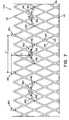
- FIG. 6shows the inner surface of an unexpanded base member in a planar profile
- FIG. 7shows the inner surface of an expanded base member in a planar profile
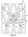
- FIG. 8is an enlarged side view of a securing element of the base member, according to a first embodiment of the securing element
- FIG. 9is a perspective view of the securing element of FIG. 8;
- FIG. 10is an enlarged side view of a securing element of the base member, according to a second embodiment of the securing element
- FIG. 11is a perspective view of the securing element of FIG. 10;
- FIG. 12is an enlarged side view of a securing element of the base member, according to a third embodiment of the securing element
- FIG. 13is a perspective view of the securing element of FIG. 12.
- FIG. 14is an enlarged perspective view of engagement means for attaching a valve member to a base member, according to an alternative embodiment of the engagement means.
- the present inventionprovides improvements to valve devices such as those disclosed in U.S. Patent Application Serial No. 11/296,899, filed December 8, 2005 , which is fully incorporated herein by reference.
- FIG. 1illustrates a fully assembled cardiovascular valve assembly 10 according to a first embodiment of the present invention.
- Valve assembly 10is basically comprised of a replaceable valve member 20 and an expandable base member 100.
- Valve member 20is generally comprised of a valve frame 30 and a plurality of pericardial leaflets 22 supported by valve frame 30.
- Base member 100is permanently installed in a patient by conventionally known means.
- Valve member 20is detachably mountable to base member 100, as will be described in detail below. It should be understood that valve member 20 and base member 100 may take forms other than as illustrated herein.
- Valve frame 30includes a wireform 40, comprised of a plurality of wireform sections 42, and coupling elements 80.
- Each wireform section 42has a generally arcuate shape, and extends between coupling elements 80.
- coupling elements 80are comprised of an upper section 84, a downward extending section 86 and an inward extending tab 88.
- An inward facing recess 82is defined by upper section 84, downward extending section 86 and tab 88.
- Fingers 50extend downward from each wireform section 42. In the illustrated embodiment, each finger 50 is located approximately in the center of wireform section 42 between adjacent coupling elements 80.
- Wireform 40may be formed of a single continuous material that comprises wireform sections 42, or may be formed of individual discrete wireform sections 42 that are joined together at coupling elements 80.
- Wireform 40is preferably made of a medical grade metal wire with suitable elasticity, such as Algiloy, nitinol, stainless steel, platinum, gold, titanium, other biocompatible metals, and combinations thereof. It should be understood that a preferred material for wireform 40 has an elasticity such that the material returns to its original shape after being deformed. However, it is contemplated that a material that does not return to its original shape after deformation could also be suitably used.
- Base member 100is generally comprised of a tubular body 110 and a mounting element 180.
- Tubular body 110has a first end 112 and a second end (not shown), and a wall 116 disposed between first end 112 and the second end.
- First end 112is the outflow end, while the second end is the inflow end, or vice versa.
- Wall 116is formed by a plurality of intersecting elongate members 122 and 124. At least some of the elongate members 122, 124 intersect with one another at intersection points 126.
- Body 110has a first diameter and is deformable to expand to a second diameter larger than the first diameter.
- Body 110is expanded by application of a radially, outwardly extending force from the interior of body 110.
- body 110may be expanded to the second diameter by inflating a balloon (e.g., a balloon catheter) located within the interior of body 110.
- the second diameter of body 110is variable and dependent upon the amount of force applied to the body 110.
- the plurality of elongate members 122, 124may be a plurality of wires.
- the wiresmay be fixedly secured to one another where the wires intersect with one another to form a wire mesh. It is contemplated that the plurality of elongate members 122, 124 may take forms other than as illustrated.
- Elongate members 122, 124are made of a material having the required strength and elastic characteristics to allow expansion of body 110 (e.g., allow plastic deformation) and to allow body 110 to retain an expanded configuration.
- suitable materials for the fabrication of body 110include silver, tantalum, stainless steel, gold, and titanium.
- tubular bodymay include mechanical tabs, teeth and/or hooks to prevent body 110 from returning to a smaller diameter after expansion, such as that used in a ratchet or in some intravascular stents.
- the plurality of elongate members 122, 124are fixedly secured to one another at intersection points 126, thereby forming a mesh tube.
- a wire mesh tubeis formed where elongate members 122, 124 are wires. It will be appreciated that elongate members 122, 124 may be fixedly secured to one another in any conventional manner (e.g., by welding, soldering, or gluing).
- mounting element 180includes an upper section 182 and a lower section 184. Sections 182 and 184 define an outward facing notch 188. Notch 188 is dimensioned to receive tab 88 of coupling element 80. Similarly, inward facing recess 82 of coupling element 80 is dimensioned to receive upper section 182 of mounting element 180.
- mounting elements 180are attached to tubular body 110 at first end 112. For example, mounting elements 180 may be welded to the inner or outer surfaces of tubular body 110, or welded to the edge of first end 112.
- FIG. 14illustrates an engagement means 260 according to an alternative embodiment.
- Engagement means 260includes a coupling member 280 having a projecting element 282 (e.g., a locking pin with a spike) and a bulb portion 283, and a mounting element 290 having a recess 292.
- Recess 292is dimensioned to mate with projecting element 282 by receiving at least a portion of projecting element 282.
- Surface 294 of recess 292conforms to the outward facing surface of projecting element 282. It should be appreciated that engagement means 60 may take forms other than those illustrated herein.
- Base member 100also includes securing elements 140 for capturing fingers 50 of valve frame 30.
- each securing element 140is comprised of a pair of arms 142, having first and second ends 144, 146, and a flexible strap 152.
- Arms 142are pivotally connected to each other at first ends 144 by fastening means (e.g., a rivet or pin).
- Second ends 146 of arms 142are pivotally connected by fastening means to the inner side of tubular body 110 at respective intersection points 126, as shown in FIGS. 8 and 9.
- Strap 152is attached at opposite ends to arms 142 by fastening means. Strap 152 extends between the pair of arms 142, thereby forming an opening 154. Opening 154 is dimensioned to receive a finger 50 of valve frame 30.
- FIGS. 10 and 11illustrate a securing element 160 according to an alternative embodiment.
- Securing element 160is comprised of a pair of arms 142, as discussed above, and an annular band 162.
- Band 162is attached to arms 142 by the same fastening means that connects arms 142 together at first ends 144.
- Band 162defines an opening 164 dimensioned to receive a finger 50 of valve frame 30.
- FIGS. 12 and 13illustrate a securing element 170 according to yet another alternative embodiment.
- Securing element 170is comprised of an annular band 172 fastened directly to the inner side of tubular body 110. As illustrated, band 172 is welded directly to an elongate member 122 or 124, preferably at an intersection point 126. Band 172 defines an opening 174 dimensioned to receive a finger 50 of valve frame 30.
- Engagement means 60together with the securing elements, maintain valve member 20 in engagement with base member 100.
- FIG. 2there is shown an unexpanded base member 100 having a first diameter and a detached valve member 20 having the first diameter.
- the diameter of valve member 20is defined by the spacing between adjacent coupling elements 80.
- base member 100is expandable to increase the diameter of tubular body 110, thereby dimensioning base member 100 to receive a valve member 20 having a larger diameter.
- FIG. 3shows an expanded base member 100 having a second diameter and a detached valve member 20 having the second diameter, wherein the second diameter is larger than the first diameter.
- the diameter of tubular body 110may be progressively increased in stages.
- body 110has detectable limits for each stage of diameter expansion. These limits may be comprised of interlocking tabs that generate variable resistance to expansion that can be felt or measured, or markers that are visible on fluoroscopy. Alternatively, limits may be set by the maximum expanded diameter of the balloon that is used to dilate tubular body 110 to the next dilated diameter.
- tubular body 110in a planar provide (i.e., unrolled as a planar mesh sheet).
- base member 100is unexpanded (i.e., first diameter)
- base member 100is expanded (i.e., second diameter).
- D and D'represent the distance between adjacent mounting elements 180.
- H and H'represents the distance between mounting element 180 of base member 100 and strap 152 of securing element 140.
- the aspect ratio D'/H'is maintained to be substantially equal to the aspect ratio D/H, as base member 100 is expanded to increase the diameter of tubular body 110.
- arms 142 of securing element 140articulate or pivot relative to each other in a downward direction away from first end 112 of body 110, as shown in FIG. 7.
- strap 152is formed of a flexible material that allows movement of arms 142. The movement of arms 142 substantially maintains the aspect ratio regardless of the amount by which the diameter of tubular body 110 is increased.
- Base member 100may be expanded, for example, by use of a balloon catheter, in a procedure similar to the placement of intracoronary stents in the field of interventional cardiology.
- the distance between mounting elements 180increases from distance D (FIG. 6) to a new distance D' (FIG. 7).
- the increased distance between mounting elements 180allows a valve member 20 of larger dimensions to be coupled to base member 100.
- the diameter of tubular body 110is increased to accept a valve frame 30 having a larger diameter.
- Securing element 160(FIGS. 10 and 11) operates in substantially the same manner as securing element 140 described above in order to substantially maintain the aspect ratio.
- securing element 170(FIGS. 12 and 13) does not substantially maintain the aspect ratio as the diameter of tubular body 110 is increased, since band 172 is directly attached to body 110 as described above. Accordingly, for the embodiment of base member 100 having securing elements 170, fingers 50 of valve frame 30 may require an increased length in order to be captured by band 172 when base member 100 is unexpanded (i.e., tubular body 110 has a small diameter).
- a base member 100is installed into the body of a patient (e.g., a pulmonary artery) by conventionally known means. It is contemplated that base member 100 is delivered percutaneously and deployed in place by way of catheter-based tools. Base member 100 may also be delivered by way of minimally invasive surgery. After installation of base member 100, tubular body 110 may dilated to a small diameter during a first procedure. A valve member 20 having a small diameter valve frame 30 can be docked with base member 100 by insertion of fingers 50 into opening 154 defined by strap 152 and the engagement of coupling element 80 with mounting element 180, as described in detail above.
- valve member 20 with the small diameter valve frame 30will be useable by a child through the first few years of life. After the child outgrows the small diameter valve frame 30, valve member 20 is detached from base member 100 by disengaging coupling element 80 from mounting element 180 and removing fingers 50 from the opening 154 defined by strap 152.
- FIG. 2illustrates the removal of a valve member 20 having a small diameter valve frame 30.
- tubular body 110 of base member 100may be further dilated (e.g., with use of a balloon) to increase the diameter thereof.
- the diameter of body 110can be determined with good precision by use of the dilating balloon.
- a valve member 20 having a larger diameter valve frame 30may then be installed in a manner similar to the installation of the original valve member 20 having the small diameter valve frame 40.
- FIG. 3illustrates the installation of a valve member 20 having a large diameter valve frame 30 after dilation of tubular body 110 to increase the diameter thereof. It should be appreciated that the diameter of tubular body 110 can be sequentially increased to receive a series of valve members 20 having incrementally larger diameter valve frames 30.
- Valve frame 30can be made to incremental diameter sizes, thereby allowing valve member 20 to be readily fit to a base member 100 having a tubular body 110 of an increased diameter.
- Valve member 20can be repeatedly "upsized” as a child grows by repeatedly enlarging or dilating tubular body 110, and replacing the current valve member 20 with a new valve member 20 having a larger diameter valve frame 30.
- cardiovascular valve assembly 10 of the present inventioncan take a child through the early stages of life onto adolescence and adulthood.
Landscapes
- Health & Medical Sciences (AREA)
- Engineering & Computer Science (AREA)
- Biomedical Technology (AREA)
- Cardiology (AREA)
- Oral & Maxillofacial Surgery (AREA)
- Transplantation (AREA)
- Heart & Thoracic Surgery (AREA)
- Vascular Medicine (AREA)
- Life Sciences & Earth Sciences (AREA)
- Animal Behavior & Ethology (AREA)
- General Health & Medical Sciences (AREA)
- Public Health (AREA)
- Veterinary Medicine (AREA)
- Prostheses (AREA)
- External Artificial Organs (AREA)
Abstract
Description
- This application claims the benefit of
U.S. Provisional Application No. 60/806,106, filed June 29, 2006 - The present invention relates generally to a cardiovascular valve assembly, and more specifically relates to a cardiovascular valve assembly comprised of a resizable base member that remains in a patient, and a valve member that is detachably mountable to the resizable base member.
U.S. Patent Application Serial No. 11/296,899 ("Cardiovascular Valve Assembly"), filed December 8, 2005 (published as U.S. Patent Application PublicationUS 2006/0136052 on June 22, 2006 ), discloses an exchangeable cardiovascular valve assembly comprised of an exchangeable valve member, which includes leaflet components, and a base member (also referred to as a "docking station"). The exchangeable valve member is detachably mounted to the base member. The base member is intended for permanent implantation within a patient. Accordingly, the base member remains inside the patient during subsequent exchanges of valve members.- A valve member may require periodic replacement due to wear. Accordingly, the current valve member is detached from the permanent base member and a new valve member is mounted thereto. It may also be necessary to replace the current valve member because the patient has grown and requires a valve member having larger dimensions. In this regard, children need frequent valve member replacements as they grow to full adult size. However, existing base members have a fixed diameter, thus preventing a simple exchange of valve members with different dimensions.
- One purpose of the present invention is to address the needs of a child patient who may have valve problems (e.g., pulmonary stenosis). Currently, these child patients are treated surgically or with a new generation of catheter deployable valves. However, catheter deployable valves are permanent devices. There is no provision for replacing such valves percutaneously when the valve fails or needs to be replaced due to sizing issues. It is generally thought that a single percutaneous deployment of a valve will avoid the first surgery and allow the patient to mature and recover for a few years until it is time for the first revision surgery.
- The present invention address the drawbacks of existing cardiovascular valve assemblies by providing a valve assembly including a resizable base member that is adaptable to receive valve members of various sizes.
- In accordance with one aspect of the present invention, there is provided a valve assembly comprising: a base member deformable to increase the dimensions thereof; and a valve member including a valve frame and a plurality of leaflets supported by the valve frame, said valve member detachably mountable to said base member.
- In accordance with another aspect of the present invention, there is provided a valve assembly comprising: (a) a base member deformable to increase the dimensions thereof, said base member including: a tubular body having an adjustable diameter, a plurality of mounting elements attached to the tubular body, a plurality of securing elements attached to the tubular body; and (b) a valve member detachably mountable to said base member, said valve member including: a valve frame and a plurality of leaflets supported by the valve frame, a plurality of coupling elements attached to the valve frame, each said coupling element engageable with a respective mounting element to detachably mount said valve member to said base member, and a plurality of fingers attached to the valve frame, each finger capturable by a respective securing element of the base member.
- An advantage of the present invention is the provision of a cardiovascular valve assembly including a base member that is expandable to receive valve members of varying dimensions.
- Still another advantage of the present invention is the provision of a cardiovascular valve assembly including an exchangeable valve member that is mountable to an expandable base member.
- These and other advantages will become apparent from the following description of embodiments of the present invention taken together with the accompanying drawings and the appended claims.
- The invention may take physical form in certain parts and arrangement of parts, embodiments of which will be described in detail in the specification and illustrated in the accompanying drawing which form a part hereof, and wherein:
- FIG. 1 illustrates a fully assembled valve assembly according to an embodiment of the present invention;
- FIG. 2 is an exploded side elevational view of a valve assembly according to the present invention, including an unexpanded base member and a valve member of a first dimension detached therefrom.
- FIG. 3 is an exploded said elevational view of a valve assembly according to the present invention, including an expanded base member and a valve member of a second dimension detached therefrom;
- FIG. 4 is a perspective view of a valve member according to the present invention, with leaflet components removed therefrom;
- FIG. 5 is an enlarged perspective view of engagement means for attaching a valve member to a base member;
- FIG. 6 shows the inner surface of an unexpanded base member in a planar profile;
- FIG. 7 shows the inner surface of an expanded base member in a planar profile;
- FIG. 8 is an enlarged side view of a securing element of the base member, according to a first embodiment of the securing element;
- FIG. 9 is a perspective view of the securing element of FIG. 8;
- FIG. 10 is an enlarged side view of a securing element of the base member, according to a second embodiment of the securing element;
- FIG. 11 is a perspective view of the securing element of FIG. 10;
- FIG. 12 is an enlarged side view of a securing element of the base member, according to a third embodiment of the securing element;
- FIG. 13 is a perspective view of the securing element of FIG. 12; and
- FIG. 14 is an enlarged perspective view of engagement means for attaching a valve member to a base member, according to an alternative embodiment of the engagement means.
- The present invention provides improvements to valve devices such as those disclosed in
U.S. Patent Application Serial No. 11/296,899, filed December 8, 2005 - Referring now to the drawings wherein the showings are for the purpose of illustrating embodiments of the present invention only and not for the purposes of limiting same, FIG. 1 illustrates a fully assembled
cardiovascular valve assembly 10 according to a first embodiment of the present invention. Valveassembly 10 is basically comprised of areplaceable valve member 20 and anexpandable base member 100. - Valve
member 20 is generally comprised of avalve frame 30 and a plurality ofpericardial leaflets 22 supported byvalve frame 30.Base member 100 is permanently installed in a patient by conventionally known means. Valvemember 20 is detachably mountable tobase member 100, as will be described in detail below. It should be understood thatvalve member 20 andbase member 100 may take forms other than as illustrated herein. - Referring now to FIG. 4, there is shown
valve frame 30 withleaflets 22 removed therefrom for improved clarity.Valve frame 30 includes awireform 40, comprised of a plurality ofwireform sections 42, andcoupling elements 80. Eachwireform section 42 has a generally arcuate shape, and extends betweencoupling elements 80. As best seen in FIG. 5,coupling elements 80 are comprised of anupper section 84, a downward extendingsection 86 and an inward extendingtab 88. An inward facingrecess 82 is defined byupper section 84, downward extendingsection 86 andtab 88.Fingers 50 extend downward from eachwireform section 42. In the illustrated embodiment, eachfinger 50 is located approximately in the center ofwireform section 42 betweenadjacent coupling elements 80. Wireform 40 may be formed of a single continuous material that compriseswireform sections 42, or may be formed of individualdiscrete wireform sections 42 that are joined together atcoupling elements 80. Wireform 40 is preferably made of a medical grade metal wire with suitable elasticity, such as Algiloy, nitinol, stainless steel, platinum, gold, titanium, other biocompatible metals, and combinations thereof. It should be understood that a preferred material forwireform 40 has an elasticity such that the material returns to its original shape after being deformed. However, it is contemplated that a material that does not return to its original shape after deformation could also be suitably used.Base member 100 is generally comprised of atubular body 110 and amounting element 180.Tubular body 110 has afirst end 112 and a second end (not shown), and awall 116 disposed betweenfirst end 112 and the second end.First end 112 is the outflow end, while the second end is the inflow end, or vice versa.Wall 116 is formed by a plurality of intersectingelongate members elongate members Body 110 has a first diameter and is deformable to expand to a second diameter larger than the first diameter.Body 110 is expanded by application of a radially, outwardly extending force from the interior ofbody 110. For example,body 110 may be expanded to the second diameter by inflating a balloon (e.g., a balloon catheter) located within the interior ofbody 110. The second diameter ofbody 110 is variable and dependent upon the amount of force applied to thebody 110.- The plurality of
elongate members elongate members Elongate members body 110 to retain an expanded configuration. By way of example, and not limitation, suitable materials for the fabrication ofbody 110 include silver, tantalum, stainless steel, gold, and titanium.- It is contemplated that in one embodiment of the present invention, tubular body may include mechanical tabs, teeth and/or hooks to prevent
body 110 from returning to a smaller diameter after expansion, such as that used in a ratchet or in some intravascular stents. - The plurality of
elongate members elongate members elongate members - As best seen in FIG. 5, mounting
element 180 includes anupper section 182 and alower section 184.Sections notch 188.Notch 188 is dimensioned to receivetab 88 ofcoupling element 80. Similarly, inward facingrecess 82 ofcoupling element 80 is dimensioned to receiveupper section 182 of mountingelement 180. In the illustrated embodiment, mountingelements 180 are attached totubular body 110 atfirst end 112. For example, mountingelements 180 may be welded to the inner or outer surfaces oftubular body 110, or welded to the edge offirst end 112. - Coupling
element 80 and mountingelement 180 are engageable with each other, and collectively form engagement means 60 for detachably mountingvalve member 20 tobase member 100. FIG. 14 illustrates an engagement means 260 according to an alternative embodiment. Engagement means 260 includes acoupling member 280 having a projecting element 282 (e.g., a locking pin with a spike) and abulb portion 283, and a mountingelement 290 having arecess 292.Recess 292 is dimensioned to mate with projectingelement 282 by receiving at least a portion of projectingelement 282.Surface 294 ofrecess 292 conforms to the outward facing surface of projectingelement 282. It should be appreciated that engagement means 60 may take forms other than those illustrated herein. A detailed description of engagement means 260 of FIG. 14, as well as a description of additional embodiments of suitable engagement means, is provided inU.S. Patent Application Serial No. 11/296,899, filed December 8, 2005 Base member 100 also includes securingelements 140 for capturingfingers 50 ofvalve frame 30. According to the embodiment shown in FIGS. 8 and 9, each securingelement 140 is comprised of a pair ofarms 142, having first and second ends 144, 146, and aflexible strap 152.Arms 142 are pivotally connected to each other at first ends 144 by fastening means (e.g., a rivet or pin). Second ends 146 ofarms 142 are pivotally connected by fastening means to the inner side oftubular body 110 at respective intersection points 126, as shown in FIGS. 8 and 9.Strap 152 is attached at opposite ends toarms 142 by fastening means.Strap 152 extends between the pair ofarms 142, thereby forming anopening 154.Opening 154 is dimensioned to receive afinger 50 ofvalve frame 30.- FIGS. 10 and 11 illustrate a securing
element 160 according to an alternative embodiment. Securingelement 160 is comprised of a pair ofarms 142, as discussed above, and anannular band 162.Band 162 is attached toarms 142 by the same fastening means that connectsarms 142 together at first ends 144.Band 162 defines an opening 164 dimensioned to receive afinger 50 ofvalve frame 30. - FIGS. 12 and 13 illustrate a securing
element 170 according to yet another alternative embodiment. Securingelement 170 is comprised of anannular band 172 fastened directly to the inner side oftubular body 110. As illustrated,band 172 is welded directly to anelongate member intersection point 126.Band 172 defines anopening 174 dimensioned to receive afinger 50 ofvalve frame 30. - Engagement means 60, together with the securing elements, maintain
valve member 20 in engagement withbase member 100. - Referring now to FIG. 2, there is shown an
unexpanded base member 100 having a first diameter and adetached valve member 20 having the first diameter. The diameter ofvalve member 20 is defined by the spacing betweenadjacent coupling elements 80. As indicated above,base member 100 is expandable to increase the diameter oftubular body 110, thereby dimensioningbase member 100 to receive avalve member 20 having a larger diameter. FIG. 3 shows an expandedbase member 100 having a second diameter and adetached valve member 20 having the second diameter, wherein the second diameter is larger than the first diameter. - The diameter of
tubular body 110 may be progressively increased in stages.
In accordance with one embodiment of the present invention,body 110 has detectable limits for each stage of diameter expansion. These limits may be comprised of interlocking tabs that generate variable resistance to expansion that can be felt or measured, or markers that are visible on fluoroscopy. Alternatively, limits may be set by the maximum expanded diameter of the balloon that is used to dilatetubular body 110 to the next dilated diameter. - Referring to FIGS. 6 and 7, there is shown
tubular body 110 in a planar provide (i.e., unrolled as a planar mesh sheet). In FIG. 6,base member 100 is unexpanded (i.e., first diameter), while in FIG. 7base member 100 is expanded (i.e., second diameter). D and D' represent the distance between adjacent mountingelements 180. H and H' represents the distance between mountingelement 180 ofbase member 100 andstrap 152 of securingelement 140. - It should be understood that upon expansion of
tubular body 110 to increase the diameter thereof, the distance between thefirst end 112 and the second end ofbody 110 will decrease. In accordance with the embodiments shown in FIGS. 8, 9 and FIGS. 10, 11, the aspect ratio D'/H' is maintained to be substantially equal to the aspect ratio D/H, asbase member 100 is expanded to increase the diameter oftubular body 110. Asbase member 100 is expanded,arms 142 of securingelement 140 articulate or pivot relative to each other in a downward direction away fromfirst end 112 ofbody 110, as shown in FIG. 7. As indicated above,strap 152 is formed of a flexible material that allows movement ofarms 142. The movement ofarms 142 substantially maintains the aspect ratio regardless of the amount by which the diameter oftubular body 110 is increased. Base member 100 may be expanded, for example, by use of a balloon catheter, in a procedure similar to the placement of intracoronary stents in the field of interventional cardiology. Astubular body 110 is dilated with a balloon (or other device), the distance between mountingelements 180 increases from distance D (FIG. 6) to a new distance D' (FIG. 7). The increased distance between mountingelements 180 allows avalve member 20 of larger dimensions to be coupled tobase member 100. In this regard, the diameter oftubular body 110 is increased to accept avalve frame 30 having a larger diameter.- Securing element 160 (FIGS. 10 and 11) operates in substantially the same manner as securing
element 140 described above in order to substantially maintain the aspect ratio. However, securing element 170 (FIGS. 12 and 13) does not substantially maintain the aspect ratio as the diameter oftubular body 110 is increased, sinceband 172 is directly attached tobody 110 as described above. Accordingly, for the embodiment ofbase member 100 having securingelements 170,fingers 50 ofvalve frame 30 may require an increased length in order to be captured byband 172 whenbase member 100 is unexpanded (i.e.,tubular body 110 has a small diameter). - Operation of
cardiovascular assembly 10 will now be described in detail with reference to the embodiment shown in FIGS. 2 and 3. Abase member 100 is installed into the body of a patient (e.g., a pulmonary artery) by conventionally known means. It is contemplated thatbase member 100 is delivered percutaneously and deployed in place by way of catheter-based tools.Base member 100 may also be delivered by way of minimally invasive surgery. After installation ofbase member 100,tubular body 110 may dilated to a small diameter during a first procedure. Avalve member 20 having a smalldiameter valve frame 30 can be docked withbase member 100 by insertion offingers 50 intoopening 154 defined bystrap 152 and the engagement ofcoupling element 80 with mountingelement 180, as described in detail above. - It is anticipated that
valve member 20 with the smalldiameter valve frame 30 will be useable by a child through the first few years of life. After the child outgrows the smalldiameter valve frame 30,valve member 20 is detached frombase member 100 by disengagingcoupling element 80 from mountingelement 180 and removingfingers 50 from theopening 154 defined bystrap 152. FIG. 2 illustrates the removal of avalve member 20 having a smalldiameter valve frame 30. Following removal ofvalve member 20 frombase member 100,tubular body 110 ofbase member 100 may be further dilated (e.g., with use of a balloon) to increase the diameter thereof. The diameter ofbody 110 can be determined with good precision by use of the dilating balloon. Avalve member 20 having a largerdiameter valve frame 30 may then be installed in a manner similar to the installation of theoriginal valve member 20 having the smalldiameter valve frame 40. FIG. 3 illustrates the installation of avalve member 20 having a largediameter valve frame 30 after dilation oftubular body 110 to increase the diameter thereof. It should be appreciated that the diameter oftubular body 110 can be sequentially increased to receive a series ofvalve members 20 having incrementally larger diameter valve frames 30. Valve frame 30 can be made to incremental diameter sizes, thereby allowingvalve member 20 to be readily fit to abase member 100 having atubular body 110 of an increased diameter.Valve member 20 can be repeatedly "upsized" as a child grows by repeatedly enlarging or dilatingtubular body 110, and replacing thecurrent valve member 20 with anew valve member 20 having a largerdiameter valve frame 30. Thus,cardiovascular valve assembly 10 of the present invention can take a child through the early stages of life onto adolescence and adulthood.
The foregoing description is a specific embodiment of the present invention. It should be appreciated that this embodiment is described for purposes of illustration only, and that numerous alterations and modifications may be practiced by those skilled in the art without departing from the spirit and scope of the invention. It is intended that all such modifications and alterations be included insofar as they come within the scope of the invention as claimed or the equivalents thereof.
Claims (18)
wherein said base member includes:
wherein said wherein said valve member further comprises:
Applications Claiming Priority (2)
| Application Number | Priority Date | Filing Date | Title |
|---|---|---|---|
| US80610606P | 2006-06-29 | 2006-06-29 | |
| US11/760,840US20080004696A1 (en) | 2006-06-29 | 2007-06-11 | Cardiovascular valve assembly with resizable docking station |
Publications (2)
| Publication Number | Publication Date |
|---|---|
| EP1872743A1true EP1872743A1 (en) | 2008-01-02 |
| EP1872743B1 EP1872743B1 (en) | 2009-08-05 |
Family
ID=38323891
Family Applications (1)
| Application Number | Title | Priority Date | Filing Date |
|---|---|---|---|
| EP07111254ANot-in-forceEP1872743B1 (en) | 2006-06-29 | 2007-06-28 | Cardiovascular valve assembly with resizable docking station |
Country Status (5)
| Country | Link |
|---|---|
| US (1) | US20080004696A1 (en) |
| EP (1) | EP1872743B1 (en) |
| AT (1) | ATE438358T1 (en) |
| CA (1) | CA2592128C (en) |
| DE (1) | DE602007001836D1 (en) |
Cited By (14)
| Publication number | Priority date | Publication date | Assignee | Title |
|---|---|---|---|---|
| WO2009108355A1 (en)* | 2008-02-28 | 2009-09-03 | Medtronic, Inc. | Prosthetic heart valve systems |
| EP2193762A1 (en)* | 2008-12-08 | 2010-06-09 | Hector Daniel Barone | Prosthetic valve for intraluminal implantation |
| WO2011109801A2 (en) | 2010-03-05 | 2011-09-09 | Edwards Lifesciences Corporation | Low-profile heart valve and delivery system |
| WO2013184895A1 (en)* | 2012-06-07 | 2013-12-12 | Boston Scientific Scimed, Inc. | Apparatus for replacing a native heart valve |
| EP2954875A1 (en)* | 2014-06-10 | 2015-12-16 | St. Jude Medical, Cardiology Division, Inc. | Stent cell bridge for cuff attachment |
| EP3167848A1 (en)* | 2009-01-12 | 2017-05-17 | Valve Medical Ltd. | Modular percutaneous valve structure and delivery device |
| EP3205309A1 (en)* | 2011-07-15 | 2017-08-16 | Edwards Lifesciences Corporation | Prosthetic heart valve |
| US9827091B2 (en) | 2010-09-20 | 2017-11-28 | St. Jude Medical, Cardiology Division, Inc. | Valve leaflet attachment in collapsible prosthetic valves |
| EP3256077A4 (en)* | 2015-02-13 | 2019-02-27 | Millipede, Inc. | VALVE REPLACEMENT USING ROTARY ANCHORS |
| US10512538B2 (en) | 2011-02-01 | 2019-12-24 | St. Jude Medical, Cardiology Division, Inc. | Leaflet suturing to commissure points for prosthetic heart valve |
| US10548731B2 (en) | 2017-02-10 | 2020-02-04 | Boston Scientific Scimed, Inc. | Implantable device and delivery system for reshaping a heart valve annulus |
| WO2020176122A1 (en) | 2019-02-28 | 2020-09-03 | Renata Medical, Inc. | Growth stent for congenital narrowings |
| US10849755B2 (en) | 2012-09-14 | 2020-12-01 | Boston Scientific Scimed, Inc. | Mitral valve inversion prostheses |
| WO2023218012A1 (en)* | 2022-05-13 | 2023-11-16 | Cormos Medical Gmbh | Artificial heart valve, device for performing a catheter-based implantation of an artificial heart valve, device for an in-situ replacement of an inner artificial heart valve, method for explanting an artificial heart valve, and method for reimplanting an artificial heart valve |
Families Citing this family (142)
| Publication number | Priority date | Publication date | Assignee | Title |
|---|---|---|---|---|
| US6006134A (en)* | 1998-04-30 | 1999-12-21 | Medtronic, Inc. | Method and device for electronically controlling the beating of a heart using venous electrical stimulation of nerve fibers |
| US6530952B2 (en) | 1997-12-29 | 2003-03-11 | The Cleveland Clinic Foundation | Bioprosthetic cardiovascular valve system |
| US8016877B2 (en)* | 1999-11-17 | 2011-09-13 | Medtronic Corevalve Llc | Prosthetic valve for transluminal delivery |
| US20070043435A1 (en)* | 1999-11-17 | 2007-02-22 | Jacques Seguin | Non-cylindrical prosthetic valve system for transluminal delivery |
| US8579966B2 (en) | 1999-11-17 | 2013-11-12 | Medtronic Corevalve Llc | Prosthetic valve for transluminal delivery |
| US7018406B2 (en)* | 1999-11-17 | 2006-03-28 | Corevalve Sa | Prosthetic valve for transluminal delivery |
| US8241274B2 (en) | 2000-01-19 | 2012-08-14 | Medtronic, Inc. | Method for guiding a medical device |
| US7749245B2 (en) | 2000-01-27 | 2010-07-06 | Medtronic, Inc. | Cardiac valve procedure methods and devices |
| AU2001273088A1 (en)* | 2000-06-30 | 2002-01-30 | Viacor Incorporated | Intravascular filter with debris entrapment mechanism |
| EP1401358B1 (en)* | 2000-06-30 | 2016-08-17 | Medtronic, Inc. | Apparatus for performing a procedure on a cardiac valve |
| US7544206B2 (en) | 2001-06-29 | 2009-06-09 | Medtronic, Inc. | Method and apparatus for resecting and replacing an aortic valve |
| US8771302B2 (en)* | 2001-06-29 | 2014-07-08 | Medtronic, Inc. | Method and apparatus for resecting and replacing an aortic valve |
| US8623077B2 (en) | 2001-06-29 | 2014-01-07 | Medtronic, Inc. | Apparatus for replacing a cardiac valve |
| FR2826863B1 (en) | 2001-07-04 | 2003-09-26 | Jacques Seguin | ASSEMBLY FOR PLACING A PROSTHETIC VALVE IN A BODY CONDUIT |
| FR2828091B1 (en) | 2001-07-31 | 2003-11-21 | Seguin Jacques | ASSEMBLY ALLOWING THE PLACEMENT OF A PROTHETIC VALVE IN A BODY DUCT |
| US7097659B2 (en) | 2001-09-07 | 2006-08-29 | Medtronic, Inc. | Fixation band for affixing a prosthetic heart valve to tissue |
| US7201771B2 (en) | 2001-12-27 | 2007-04-10 | Arbor Surgical Technologies, Inc. | Bioprosthetic heart valve |
| US7959674B2 (en)* | 2002-07-16 | 2011-06-14 | Medtronic, Inc. | Suture locking assembly and method of use |
| CO5500017A1 (en)* | 2002-09-23 | 2005-03-31 | 3F Therapeutics Inc | MITRAL PROTESTIC VALVE |
| US8551162B2 (en) | 2002-12-20 | 2013-10-08 | Medtronic, Inc. | Biologically implantable prosthesis |
| US7393339B2 (en)* | 2003-02-21 | 2008-07-01 | C. R. Bard, Inc. | Multi-lumen catheter with separate distal tips |
| US8021421B2 (en)* | 2003-08-22 | 2011-09-20 | Medtronic, Inc. | Prosthesis heart valve fixturing device |
| US9579194B2 (en)* | 2003-10-06 | 2017-02-28 | Medtronic ATS Medical, Inc. | Anchoring structure with concave landing zone |
| US7556647B2 (en)* | 2003-10-08 | 2009-07-07 | Arbor Surgical Technologies, Inc. | Attachment device and methods of using the same |
| US7959666B2 (en) | 2003-12-23 | 2011-06-14 | Sadra Medical, Inc. | Methods and apparatus for endovascularly replacing a heart valve |
| US20050137687A1 (en) | 2003-12-23 | 2005-06-23 | Sadra Medical | Heart valve anchor and method |
| ITTO20040135A1 (en) | 2004-03-03 | 2004-06-03 | Sorin Biomedica Cardio Spa | CARDIAC VALVE PROSTHESIS |
| BRPI0510107A (en) | 2004-04-23 | 2007-09-25 | 3F Therapeutics Inc | implantable protein valve |
| US20080015671A1 (en)* | 2004-11-19 | 2008-01-17 | Philipp Bonhoeffer | Method And Apparatus For Treatment Of Cardiac Valves |
| US7758640B2 (en)* | 2004-12-16 | 2010-07-20 | Valvexchange Inc. | Cardiovascular valve assembly |
| DE102005003632A1 (en) | 2005-01-20 | 2006-08-17 | Fraunhofer-Gesellschaft zur Förderung der angewandten Forschung e.V. | Catheter for the transvascular implantation of heart valve prostheses |
| ITTO20050074A1 (en) | 2005-02-10 | 2006-08-11 | Sorin Biomedica Cardio Srl | CARDIAC VALVE PROSTHESIS |
| US7513909B2 (en)* | 2005-04-08 | 2009-04-07 | Arbor Surgical Technologies, Inc. | Two-piece prosthetic valves with snap-in connection and methods for use |
| US7914569B2 (en) | 2005-05-13 | 2011-03-29 | Medtronics Corevalve Llc | Heart valve prosthesis and methods of manufacture and use |
| US8211169B2 (en) | 2005-05-27 | 2012-07-03 | Medtronic, Inc. | Gasket with collar for prosthetic heart valves and methods for using them |
| EP1945142B1 (en) | 2005-09-26 | 2013-12-25 | Medtronic, Inc. | Prosthetic cardiac and venous valves |
| US7967857B2 (en) | 2006-01-27 | 2011-06-28 | Medtronic, Inc. | Gasket with spring collar for prosthetic heart valves and methods for making and using them |
| JP5102279B2 (en)* | 2006-03-10 | 2012-12-19 | メドトロニック,インコーポレイテッド | Artificial valve introducer, method for producing the same and method for using the same |
| US8075615B2 (en)* | 2006-03-28 | 2011-12-13 | Medtronic, Inc. | Prosthetic cardiac valve formed from pericardium material and methods of making same |
| JP2009535128A (en)* | 2006-04-29 | 2009-10-01 | アーバー・サージカル・テクノロジーズ・インコーポレイテッド | Multi-part prosthetic heart valve assembly and apparatus and method for delivering the same |
| US9408607B2 (en) | 2009-07-02 | 2016-08-09 | Edwards Lifesciences Cardiaq Llc | Surgical implant devices and methods for their manufacture and use |
| US9585743B2 (en) | 2006-07-31 | 2017-03-07 | Edwards Lifesciences Cardiaq Llc | Surgical implant devices and methods for their manufacture and use |
| EP3360509B1 (en) | 2006-07-31 | 2022-06-22 | Syntheon TAVR, LLC | Sealable endovascular implants |
| US8876894B2 (en) | 2006-09-19 | 2014-11-04 | Medtronic Ventor Technologies Ltd. | Leaflet-sensitive valve fixation member |
| US8834564B2 (en)* | 2006-09-19 | 2014-09-16 | Medtronic, Inc. | Sinus-engaging valve fixation member |
| US11304800B2 (en) | 2006-09-19 | 2022-04-19 | Medtronic Ventor Technologies Ltd. | Sinus-engaging valve fixation member |
| DK2083901T3 (en) | 2006-10-16 | 2018-02-26 | Medtronic Ventor Tech Ltd | TRANSAPICAL DELIVERY SYSTEM WITH VENTRICULO-ARTERIAL OVERFLOW BYPASS |
| JP5593545B2 (en)* | 2006-12-06 | 2014-09-24 | メドトロニック シーブイ ルクセンブルク エス.アー.エール.エル. | System and method for transapical delivery of a self-expanding valve secured to an annulus |
| US8460369B2 (en)* | 2007-01-18 | 2013-06-11 | Valvexchange Inc. | Tools for removal and installation of exchangeable cardiovascular valves |
| AU2008216670B2 (en)* | 2007-02-15 | 2013-10-17 | Medtronic, Inc. | Multi-layered stents and methods of implanting |
| US8639800B2 (en)* | 2007-02-16 | 2014-01-28 | Forescout Technologies, Inc. | Method and device for determining network device status |
| EP2129332B1 (en)* | 2007-02-16 | 2019-01-23 | Medtronic, Inc. | Replacement prosthetic heart valves |
| US8092523B2 (en)* | 2007-03-12 | 2012-01-10 | St. Jude Medical, Inc. | Prosthetic heart valves with flexible leaflets |
| US7896915B2 (en) | 2007-04-13 | 2011-03-01 | Jenavalve Technology, Inc. | Medical device for treating a heart valve insufficiency |
| FR2915087B1 (en) | 2007-04-20 | 2021-11-26 | Corevalve Inc | IMPLANT FOR TREATMENT OF A HEART VALVE, IN PARTICULAR OF A MITRAL VALVE, EQUIPMENT INCLUDING THIS IMPLANT AND MATERIAL FOR PLACING THIS IMPLANT. |
| US9566178B2 (en)* | 2010-06-24 | 2017-02-14 | Edwards Lifesciences Cardiaq Llc | Actively controllable stent, stent graft, heart valve and method of controlling same |
| US9814611B2 (en) | 2007-07-31 | 2017-11-14 | Edwards Lifesciences Cardiaq Llc | Actively controllable stent, stent graft, heart valve and method of controlling same |
| US8747458B2 (en) | 2007-08-20 | 2014-06-10 | Medtronic Ventor Technologies Ltd. | Stent loading tool and method for use thereof |
| CA2696055C (en) | 2007-08-21 | 2013-12-10 | Valvexchange Inc. | Method and apparatus for prosthetic valve removal |
| US10856970B2 (en) | 2007-10-10 | 2020-12-08 | Medtronic Ventor Technologies Ltd. | Prosthetic heart valve for transfemoral delivery |
| US9848981B2 (en) | 2007-10-12 | 2017-12-26 | Mayo Foundation For Medical Education And Research | Expandable valve prosthesis with sealing mechanism |
| CA2714062A1 (en) | 2008-01-24 | 2009-07-30 | Medtronic, Inc. | Stents for prosthetic heart valves |
| US9089422B2 (en) | 2008-01-24 | 2015-07-28 | Medtronic, Inc. | Markers for prosthetic heart valves |
| US9149358B2 (en)* | 2008-01-24 | 2015-10-06 | Medtronic, Inc. | Delivery systems for prosthetic heart valves |
| US8157853B2 (en) | 2008-01-24 | 2012-04-17 | Medtronic, Inc. | Delivery systems and methods of implantation for prosthetic heart valves |
| US8628566B2 (en)* | 2008-01-24 | 2014-01-14 | Medtronic, Inc. | Stents for prosthetic heart valves |
| US20090287290A1 (en)* | 2008-01-24 | 2009-11-19 | Medtronic, Inc. | Delivery Systems and Methods of Implantation for Prosthetic Heart Valves |
| US9393115B2 (en)* | 2008-01-24 | 2016-07-19 | Medtronic, Inc. | Delivery systems and methods of implantation for prosthetic heart valves |
| US9044318B2 (en) | 2008-02-26 | 2015-06-02 | Jenavalve Technology Gmbh | Stent for the positioning and anchoring of a valvular prosthesis |
| BR112012021347A2 (en) | 2008-02-26 | 2019-09-24 | Jenavalve Tecnology Inc | stent for positioning and anchoring a valve prosthesis at an implantation site in a patient's heart |
| US8313525B2 (en) | 2008-03-18 | 2012-11-20 | Medtronic Ventor Technologies, Ltd. | Valve suturing and implantation procedures |
| US8430927B2 (en) | 2008-04-08 | 2013-04-30 | Medtronic, Inc. | Multiple orifice implantable heart valve and methods of implantation |
| US8696743B2 (en)* | 2008-04-23 | 2014-04-15 | Medtronic, Inc. | Tissue attachment devices and methods for prosthetic heart valves |
| US8312825B2 (en) | 2008-04-23 | 2012-11-20 | Medtronic, Inc. | Methods and apparatuses for assembly of a pericardial prosthetic heart valve |
| EP2119417B2 (en) | 2008-05-16 | 2020-04-29 | Sorin Group Italia S.r.l. | Atraumatic prosthetic heart valve prosthesis |
| US9039756B2 (en) | 2008-07-21 | 2015-05-26 | Jenesis Surgical, Llc | Repositionable endoluminal support structure and its applications |
| CN102245129B (en) | 2008-07-21 | 2015-03-18 | 詹妮弗·K·怀特 | Repositionable intraluminal support structures and their applications |
| WO2010030859A1 (en)* | 2008-09-12 | 2010-03-18 | Valvexchange Inc. | Valve assembly with exchangeable valve member and a tool set for exchanging the valve member |
| WO2010031060A1 (en) | 2008-09-15 | 2010-03-18 | Medtronic Ventor Technologies Ltd. | Prosthetic heart valve having identifiers for aiding in radiographic positioning |
| US8721714B2 (en) | 2008-09-17 | 2014-05-13 | Medtronic Corevalve Llc | Delivery system for deployment of medical devices |
| US8137398B2 (en) | 2008-10-13 | 2012-03-20 | Medtronic Ventor Technologies Ltd | Prosthetic valve having tapered tip when compressed for delivery |
| US8986361B2 (en) | 2008-10-17 | 2015-03-24 | Medtronic Corevalve, Inc. | Delivery system for deployment of medical devices |
| EP2682072A1 (en) | 2008-12-23 | 2014-01-08 | Sorin Group Italia S.r.l. | Expandable prosthetic valve having anchoring appendages |
| EP2246011B1 (en) | 2009-04-27 | 2014-09-03 | Sorin Group Italia S.r.l. | Prosthetic vascular conduit |
| US8808369B2 (en)* | 2009-10-05 | 2014-08-19 | Mayo Foundation For Medical Education And Research | Minimally invasive aortic valve replacement |
| US9226826B2 (en)* | 2010-02-24 | 2016-01-05 | Medtronic, Inc. | Transcatheter valve structure and methods for valve delivery |
| WO2011120050A1 (en)* | 2010-03-26 | 2011-09-29 | Thubrikar Aortic Valve, Inc. | Valve component, frame component and prosthetic valve device including the same for implantation in a body lumen |
| US8652204B2 (en) | 2010-04-01 | 2014-02-18 | Medtronic, Inc. | Transcatheter valve with torsion spring fixation and related systems and methods |
| US8579964B2 (en) | 2010-05-05 | 2013-11-12 | Neovasc Inc. | Transcatheter mitral valve prosthesis |
| US10856978B2 (en) | 2010-05-20 | 2020-12-08 | Jenavalve Technology, Inc. | Catheter system |
| IT1400327B1 (en) | 2010-05-21 | 2013-05-24 | Sorin Biomedica Cardio Srl | SUPPORT DEVICE FOR VALVULAR PROSTHESIS AND CORRESPONDING CORRESPONDENT. |
| WO2011147849A1 (en) | 2010-05-25 | 2011-12-01 | Jenavalve Technology Inc. | Prosthetic heart valve and transcatheter delivered endoprosthesis comprising a prosthetic heart valve and a stent |
| US9039759B2 (en) | 2010-08-24 | 2015-05-26 | St. Jude Medical, Cardiology Division, Inc. | Repositioning of prosthetic heart valve and deployment |
| WO2012030598A2 (en)* | 2010-09-01 | 2012-03-08 | Medtronic Vascular Galway Limited | Prosthetic valve support structure |
| EP2486894B1 (en) | 2011-02-14 | 2021-06-09 | Sorin Group Italia S.r.l. | Sutureless anchoring device for cardiac valve prostheses |
| ES2641902T3 (en) | 2011-02-14 | 2017-11-14 | Sorin Group Italia S.R.L. | Sutureless anchoring device for cardiac valve prostheses |
| US9554897B2 (en) | 2011-04-28 | 2017-01-31 | Neovasc Tiara Inc. | Methods and apparatus for engaging a valve prosthesis with tissue |
| US9308087B2 (en) | 2011-04-28 | 2016-04-12 | Neovasc Tiara Inc. | Sequentially deployed transcatheter mitral valve prosthesis |
| US9827093B2 (en) | 2011-10-21 | 2017-11-28 | Edwards Lifesciences Cardiaq Llc | Actively controllable stent, stent graft, heart valve and method of controlling same |
| EP2842517A1 (en) | 2011-12-29 | 2015-03-04 | Sorin Group Italia S.r.l. | A kit for implanting prosthetic vascular conduits |
| EP2802290B1 (en)* | 2012-01-10 | 2018-07-11 | Jenesis Surgical, LLC | Articulated support structure with secondary strut features |
| US9345573B2 (en) | 2012-05-30 | 2016-05-24 | Neovasc Tiara Inc. | Methods and apparatus for loading a prosthesis onto a delivery system |
| CN107184292B (en) | 2013-03-13 | 2020-07-10 | 爱德华兹生命科学卡迪尔克有限责任公司 | Articulating commissure valve stents and methods |
| US9572665B2 (en) | 2013-04-04 | 2017-02-21 | Neovasc Tiara Inc. | Methods and apparatus for delivering a prosthetic valve to a beating heart |
| WO2014179763A1 (en) | 2013-05-03 | 2014-11-06 | Medtronic Inc. | Valve delivery tool |
| CN105491978A (en) | 2013-08-30 | 2016-04-13 | 耶拿阀门科技股份有限公司 | Radially collapsible frame for a prosthetic valve and method for manufacturing such a frame |
| US9867611B2 (en)* | 2013-09-05 | 2018-01-16 | St. Jude Medical, Cardiology Division, Inc. | Anchoring studs for transcatheter valve implantation |
| CR20160240A (en) | 2013-11-11 | 2016-08-04 | Edwards Lifesciences Cardiaq Llc | SYSTEMS AND METHODS FOR THE MANUFACTURE OF THE FRAME OF A CANNULA |
| US9763778B2 (en) | 2014-03-18 | 2017-09-19 | St. Jude Medical, Cardiology Division, Inc. | Aortic insufficiency valve percutaneous valve anchoring |
| EP3270825B1 (en) | 2015-03-20 | 2020-04-22 | JenaValve Technology, Inc. | Heart valve prosthesis delivery system |
| US10709555B2 (en) | 2015-05-01 | 2020-07-14 | Jenavalve Technology, Inc. | Device and method with reduced pacemaker rate in heart valve replacement |
| CA3007660A1 (en) | 2015-12-15 | 2017-06-22 | Neovasc Tiara Inc. | Transseptal delivery system |
| US11833034B2 (en) | 2016-01-13 | 2023-12-05 | Shifamed Holdings, Llc | Prosthetic cardiac valve devices, systems, and methods |
| US10433952B2 (en) | 2016-01-29 | 2019-10-08 | Neovasc Tiara Inc. | Prosthetic valve for avoiding obstruction of outflow |
| US10363130B2 (en) | 2016-02-05 | 2019-07-30 | Edwards Lifesciences Corporation | Devices and systems for docking a heart valve |
| WO2017195125A1 (en) | 2016-05-13 | 2017-11-16 | Jenavalve Technology, Inc. | Heart valve prosthesis delivery system and method for delivery of heart valve prosthesis with introducer sheath and loading system |
| CA3042588A1 (en) | 2016-11-21 | 2018-05-24 | Neovasc Tiara Inc. | Methods and systems for rapid retraction of a transcatheter heart valve delivery system |
| WO2018138658A1 (en) | 2017-01-27 | 2018-08-02 | Jenavalve Technology, Inc. | Heart valve mimicry |
| USD867595S1 (en) | 2017-02-01 | 2019-11-19 | Edwards Lifesciences Corporation | Stent |
| EP4397285A3 (en) | 2017-06-30 | 2024-09-25 | Edwards Lifesciences Corporation | Lock and release mechanisms for trans-catheter implantable devices |
| CN116196149A (en)* | 2017-06-30 | 2023-06-02 | 爱德华兹生命科学公司 | Transcatheter valve docking station |
| CA3073834A1 (en) | 2017-08-25 | 2019-02-28 | Neovasc Tiara Inc. | Sequentially deployed transcatheter mitral valve prosthesis |
| JP7074930B2 (en) | 2018-05-23 | 2022-05-24 | コーシム・ソチエタ・ア・レスポンサビリタ・リミタータ | Device for in-situ delivery of heart valve prosthesis |
| AU2018424859B2 (en) | 2018-05-23 | 2024-04-04 | Corcym S.R.L. | A cardiac valve prosthesis |
| AU2019325548B2 (en) | 2018-08-21 | 2025-06-26 | Shifamed Holdings, Llc | Prosthetic cardiac valve devices, systems, and methods |
| CN113260337A (en) | 2018-10-05 | 2021-08-13 | 施菲姆德控股有限责任公司 | Prosthetic heart valve devices, systems, and methods |
| CN113056302B (en) | 2018-10-19 | 2023-03-28 | 施菲姆德控股有限责任公司 | Adjustable medical device |
| CN113271890B (en) | 2018-11-08 | 2024-08-30 | 内奥瓦斯克迪亚拉公司 | Ventricular deployment of transcatheter mitral valve prosthesis |
| CA3132873A1 (en) | 2019-03-08 | 2020-09-17 | Neovasc Tiara Inc. | Retrievable prosthesis delivery system |
| EP3941391B1 (en) | 2019-03-19 | 2024-12-04 | Shifamed Holdings, LLC | Prosthetic cardiac valve devices, systems |
| US11559415B2 (en) | 2019-03-26 | 2023-01-24 | Edwards Lifesciences Corporation | Radially self-expanding stents |
| WO2020197869A1 (en)* | 2019-03-26 | 2020-10-01 | Edwards Lifesciences Corporation | Self growing heart valves |
| CA3135753C (en) | 2019-04-01 | 2023-10-24 | Neovasc Tiara Inc. | Controllably deployable prosthetic valve |
| US11491006B2 (en) | 2019-04-10 | 2022-11-08 | Neovasc Tiara Inc. | Prosthetic valve with natural blood flow |
| US11779742B2 (en) | 2019-05-20 | 2023-10-10 | Neovasc Tiara Inc. | Introducer with hemostasis mechanism |
| JP7520897B2 (en) | 2019-06-20 | 2024-07-23 | ニオバスク ティアラ インコーポレイテッド | Thin prosthetic mitral valve |
| ES3031166T3 (en)* | 2020-06-23 | 2025-07-04 | Edwards Lifesciences Corp | Prosthetic implant systems for diameter adaptation |
| CN116456937A (en) | 2020-08-31 | 2023-07-18 | 施菲姆德控股有限责任公司 | Prosthetic Valve Delivery System |
| US12329635B2 (en) | 2020-12-04 | 2025-06-17 | Shifamed Holdings, Llc | Flared prosthetic cardiac valve delivery devices and systems |
| US12201521B2 (en) | 2021-03-22 | 2025-01-21 | Shifamed Holdings, Llc | Anchor position verification for prosthetic cardiac valve devices |
| WO2024102411A1 (en) | 2022-11-09 | 2024-05-16 | Jenavalve Technology, Inc. | Catheter system for sequential deployment of an expandable implant |
| EP4629933A1 (en) | 2022-12-09 | 2025-10-15 | Renata Medical, Inc. | Transcatheter growth devices and methods for norwood, glenn and fontan therapy |
Citations (4)
| Publication number | Priority date | Publication date | Assignee | Title |
|---|---|---|---|---|
| US6454799B1 (en) | 2000-04-06 | 2002-09-24 | Edwards Lifesciences Corporation | Minimally-invasive heart valves and methods of use |
| US20040030381A1 (en) | 2002-07-16 | 2004-02-12 | Shu Mark C.S. | Heart valve prosthesis |
| US20060136052A1 (en) | 2004-12-16 | 2006-06-22 | Valvexchange Inc. | Cardiovascular valve assembly |
| WO2006127756A2 (en) | 2005-05-24 | 2006-11-30 | Edwards Lifesciences Corporation | Rapid deployment prosthetic heart valve |
Family Cites Families (90)
| Publication number | Priority date | Publication date | Assignee | Title |
|---|---|---|---|---|
| US3839741A (en)* | 1972-11-17 | 1974-10-08 | J Haller | Heart valve and retaining means therefor |
| US3898701A (en)* | 1974-01-17 | 1975-08-12 | Russa Joseph | Implantable heart valve |
| US4056854A (en)* | 1976-09-28 | 1977-11-08 | The United States Of America As Represented By The Department Of Health, Education And Welfare | Aortic heart valve catheter |
| US4501030A (en)* | 1981-08-17 | 1985-02-26 | American Hospital Supply Corporation | Method of leaflet attachment for prosthetic heart valves |
| US4680031A (en)* | 1982-11-29 | 1987-07-14 | Tascon Medical Technology Corporation | Heart valve prosthesis |
| US4506394A (en)* | 1983-01-13 | 1985-03-26 | Molrose Management, Ltd. | Cardiac valve prosthesis holder |
| US4535483A (en)* | 1983-01-17 | 1985-08-20 | Hemex, Inc. | Suture rings for heart valves |
| AR229309A1 (en)* | 1983-04-20 | 1983-07-15 | Barone Hector Daniel | MOUNT FOR CARDIAC VALVES |
| GB8424582D0 (en)* | 1984-09-28 | 1984-11-07 | Univ Glasgow | Heart valve prosthesis |
| US4733665C2 (en)* | 1985-11-07 | 2002-01-29 | Expandable Grafts Partnership | Expandable intraluminal graft and method and apparatus for implanting an expandable intraluminal graft |
| US4909789A (en)* | 1986-03-28 | 1990-03-20 | Olympus Optical Co., Ltd. | Observation assisting forceps |
| SE453258B (en)* | 1986-04-21 | 1988-01-25 | Medinvent Sa | ELASTIC, SELF-EXPANDING PROTEST AND PROCEDURE FOR ITS MANUFACTURING |
| US4790843A (en)* | 1986-06-16 | 1988-12-13 | Baxter Travenol Laboratories, Inc. | Prosthetic heart valve assembly |
| JPS63238872A (en)* | 1987-03-25 | 1988-10-04 | テルモ株式会社 | Instrument for securing inner diameter of cavity of tubular organ and catheter equipped therewith |
| DE3715867A1 (en)* | 1987-05-07 | 1988-11-24 | Schering Ag | METHOD FOR WASTEWATER CLEANING |
| DK124690D0 (en)* | 1990-05-18 | 1990-05-18 | Henning Rud Andersen | FAT PROTECTION FOR IMPLEMENTATION IN THE BODY FOR REPLACEMENT OF NATURAL FLEET AND CATS FOR USE IN IMPLEMENTING A SUCH FAT PROTECTION |
| US5411552A (en)* | 1990-05-18 | 1995-05-02 | Andersen; Henning R. | Valve prothesis for implantation in the body and a catheter for implanting such valve prothesis |
| DE4021153A1 (en)* | 1990-07-03 | 1992-01-16 | Wolf Gmbh Richard | ORGAN MANIPULATOR |
| DE69123982T2 (en)* | 1990-11-20 | 1997-12-04 | Innerdyne Medical Inc | STRETCH MAINTENANCE GUIDE ELEMENT AND DILATATOR |
| US5163955A (en)* | 1991-01-24 | 1992-11-17 | Autogenics | Rapid assembly, concentric mating stent, tissue heart valve with enhanced clamping and tissue alignment |
| US5197978B1 (en)* | 1991-04-26 | 1996-05-28 | Advanced Coronary Tech | Removable heat-recoverable tissue supporting device |
| US5370685A (en)* | 1991-07-16 | 1994-12-06 | Stanford Surgical Technologies, Inc. | Endovascular aortic valve replacement |
| US5163953A (en)* | 1992-02-10 | 1992-11-17 | Vince Dennis J | Toroidal artificial heart valve stent |
| US5509900A (en)* | 1992-03-02 | 1996-04-23 | Kirkman; Thomas R. | Apparatus and method for retaining a catheter in a blood vessel in a fixed position |
| NL9201118A (en)* | 1992-06-24 | 1994-01-17 | Leuven K U Res & Dev | TOOL KIT FOR LAPAROSCOPIC VAGINAL HYSTERECTOMY. |
| US5718725A (en)* | 1992-12-03 | 1998-02-17 | Heartport, Inc. | Devices and methods for intracardiac procedures |
| GB9312666D0 (en)* | 1993-06-18 | 1993-08-04 | Vesely Ivan | Bioprostetic heart valve |
| US5554185A (en)* | 1994-07-18 | 1996-09-10 | Block; Peter C. | Inflatable prosthetic cardiovascular valve for percutaneous transluminal implantation of same |
| US5593424A (en)* | 1994-08-10 | 1997-01-14 | Segmed, Inc. | Apparatus and method for reducing and stabilizing the circumference of a vascular structure |
| US5607446A (en)* | 1995-01-31 | 1997-03-04 | Beehler; Cecil C. | Pupil dilator |
| AU719980B2 (en)* | 1995-02-22 | 2000-05-18 | Menlo Care, Inc. | Covered expanding mesh stent |
| US5807405A (en)* | 1995-09-11 | 1998-09-15 | St. Jude Medical, Inc. | Apparatus for attachment of heart valve holder to heart valve prosthesis |
| US6579305B1 (en)* | 1995-12-07 | 2003-06-17 | Medtronic Ave, Inc. | Method and apparatus for delivery deployment and retrieval of a stent comprising shape-memory material |
| US6402780B2 (en)* | 1996-02-23 | 2002-06-11 | Cardiovascular Technologies, L.L.C. | Means and method of replacing a heart valve in a minimally invasive manner |
| US5855601A (en)* | 1996-06-21 | 1999-01-05 | The Trustees Of Columbia University In The City Of New York | Artificial heart valve and method and device for implanting the same |
| US5755783A (en)* | 1996-07-29 | 1998-05-26 | Stobie; Robert | Suture rings for rotatable artificial heart valves |
| US6217585B1 (en)* | 1996-08-16 | 2001-04-17 | Converge Medical, Inc. | Mechanical stent and graft delivery system |
| US5961545A (en)* | 1997-01-17 | 1999-10-05 | Meadox Medicals, Inc. | EPTFE graft-stent composite device |
| US5928281A (en)* | 1997-03-27 | 1999-07-27 | Baxter International Inc. | Tissue heart valves |
| US5957949A (en)* | 1997-05-01 | 1999-09-28 | World Medical Manufacturing Corp. | Percutaneous placement valve stent |
| US6168616B1 (en)* | 1997-06-02 | 2001-01-02 | Global Vascular Concepts | Manually expandable stent |
| US5899935A (en)* | 1997-08-04 | 1999-05-04 | Schneider (Usa) Inc. | Balloon expandable braided stent with restraint |
| US5910170A (en)* | 1997-12-17 | 1999-06-08 | St. Jude Medical, Inc. | Prosthetic heart valve stent utilizing mounting clips |
| EP1049425B1 (en)* | 1997-12-29 | 2009-11-25 | Cleveland Clinic Foundation The | System for minimally invasive insertion of a bioprosthetic heart valve |
| US6530952B2 (en)* | 1997-12-29 | 2003-03-11 | The Cleveland Clinic Foundation | Bioprosthetic cardiovascular valve system |
| US6241762B1 (en)* | 1998-03-30 | 2001-06-05 | Conor Medsystems, Inc. | Expandable medical device with ductile hinges |
| US6074418A (en)* | 1998-04-20 | 2000-06-13 | St. Jude Medical, Inc. | Driver tool for heart valve prosthesis fasteners |
| US6106550A (en)* | 1998-07-10 | 2000-08-22 | Sulzer Carbomedics Inc. | Implantable attaching ring |
| US6197054B1 (en)* | 1998-09-01 | 2001-03-06 | Sulzer Carbomedics Inc. | Sutureless cuff for heart valves |
| US6558418B2 (en)* | 1999-01-26 | 2003-05-06 | Edwards Lifesciences Corporation | Flexible heart valve |
| US6299638B1 (en)* | 1999-06-10 | 2001-10-09 | Sulzer Carbomedics Inc. | Method of attachment of large-bore aortic graft to an aortic valve |
| US6312465B1 (en)* | 1999-07-23 | 2001-11-06 | Sulzer Carbomedics Inc. | Heart valve prosthesis with a resiliently deformable retaining member |
| US6371983B1 (en)* | 1999-10-04 | 2002-04-16 | Ernest Lane | Bioprosthetic heart valve |
| US6893459B1 (en)* | 2000-09-20 | 2005-05-17 | Ample Medical, Inc. | Heart valve annulus device and method of using same |
| US6461382B1 (en)* | 2000-09-22 | 2002-10-08 | Edwards Lifesciences Corporation | Flexible heart valve having moveable commissures |
| US6733525B2 (en)* | 2001-03-23 | 2004-05-11 | Edwards Lifesciences Corporation | Rolled minimally-invasive heart valves and methods of use |
| US7374571B2 (en)* | 2001-03-23 | 2008-05-20 | Edwards Lifesciences Corporation | Rolled minimally-invasive heart valves and methods of manufacture |
| US7201771B2 (en)* | 2001-12-27 | 2007-04-10 | Arbor Surgical Technologies, Inc. | Bioprosthetic heart valve |
| US7172625B2 (en)* | 2002-07-16 | 2007-02-06 | Medtronic, Inc. | Suturing rings for implantable heart valve prostheses |
| US7041132B2 (en)* | 2002-08-16 | 2006-05-09 | 3F Therapeutics, Inc, | Percutaneously delivered heart valve and delivery means thereof |
| US7399315B2 (en)* | 2003-03-18 | 2008-07-15 | Edwards Lifescience Corporation | Minimally-invasive heart valve with cusp positioners |
| US20040225356A1 (en)* | 2003-05-09 | 2004-11-11 | Frater Robert W. | Flexible heart valve |
| US7235093B2 (en)* | 2003-05-20 | 2007-06-26 | Boston Scientific Scimed, Inc. | Mechanism to improve stent securement |
| BRPI0412362A (en)* | 2003-07-08 | 2006-09-05 | Ventor Technologies Ltd | prosthetic implant devices particularly for transarterial transport in the treatment of aortic stenoses and implantation methods for such devices |
| US20050075719A1 (en)* | 2003-10-06 | 2005-04-07 | Bjarne Bergheim | Minimally invasive valve replacement system |
| US7186265B2 (en)* | 2003-12-10 | 2007-03-06 | Medtronic, Inc. | Prosthetic cardiac valves and systems and methods for implanting thereof |
| US7780725B2 (en)* | 2004-06-16 | 2010-08-24 | Sadra Medical, Inc. | Everting heart valve |
| US7445631B2 (en)* | 2003-12-23 | 2008-11-04 | Sadra Medical, Inc. | Methods and apparatus for endovascularly replacing a patient's heart valve |
| US7824442B2 (en)* | 2003-12-23 | 2010-11-02 | Sadra Medical, Inc. | Methods and apparatus for endovascularly replacing a heart valve |
| US7824443B2 (en)* | 2003-12-23 | 2010-11-02 | Sadra Medical, Inc. | Medical implant delivery and deployment tool |
| US7381219B2 (en)* | 2003-12-23 | 2008-06-03 | Sadra Medical, Inc. | Low profile heart valve and delivery system |
| US9526609B2 (en)* | 2003-12-23 | 2016-12-27 | Boston Scientific Scimed, Inc. | Methods and apparatus for endovascularly replacing a patient's heart valve |
| US8182528B2 (en)* | 2003-12-23 | 2012-05-22 | Sadra Medical, Inc. | Locking heart valve anchor |
| US7329279B2 (en)* | 2003-12-23 | 2008-02-12 | Sadra Medical, Inc. | Methods and apparatus for endovascularly replacing a patient's heart valve |
| US7959666B2 (en)* | 2003-12-23 | 2011-06-14 | Sadra Medical, Inc. | Methods and apparatus for endovascularly replacing a heart valve |
| US8343213B2 (en)* | 2003-12-23 | 2013-01-01 | Sadra Medical, Inc. | Leaflet engagement elements and methods for use thereof |
| WO2005069850A2 (en)* | 2004-01-15 | 2005-08-04 | Macoviak John A | Trestle heart valve replacement |
| US7597711B2 (en)* | 2004-01-26 | 2009-10-06 | Arbor Surgical Technologies, Inc. | Heart valve assembly with slidable coupling connections |
| CA2813136A1 (en)* | 2004-02-27 | 2005-09-15 | Aortx, Inc. | Prosthetic heart valve delivery systems and methods |
| US20050228494A1 (en)* | 2004-03-29 | 2005-10-13 | Salvador Marquez | Controlled separation heart valve frame |
| US7331991B2 (en)* | 2005-02-25 | 2008-02-19 | California Institute Of Technology | Implantable small percutaneous valve and methods of delivery |
| US20060195186A1 (en)* | 2005-02-28 | 2006-08-31 | Drews Michael J | Connectors for two piece heart valves and methods for implanting such heart valves |
| US20070016288A1 (en)* | 2005-07-13 | 2007-01-18 | Gurskis Donnell W | Two-piece percutaneous prosthetic heart valves and methods for making and using them |
| EP1988851A2 (en)* | 2006-02-14 | 2008-11-12 | Sadra Medical, Inc. | Systems and methods for delivering a medical implant |
| US7534261B2 (en)* | 2006-10-02 | 2009-05-19 | Edwards Lifesciences Corporation | Sutureless heart valve attachment |
| WO2008091493A1 (en)* | 2007-01-08 | 2008-07-31 | California Institute Of Technology | In-situ formation of a valve |
| US8460369B2 (en)* | 2007-01-18 | 2013-06-11 | Valvexchange Inc. | Tools for removal and installation of exchangeable cardiovascular valves |
| EP2129332B1 (en)* | 2007-02-16 | 2019-01-23 | Medtronic, Inc. | Replacement prosthetic heart valves |
| PL4223257T3 (en)* | 2008-06-06 | 2024-09-23 | Edwards Lifesciences Corporation | LOW-PROFILE TRANSCATHETIC HEART VALVE |
| EP3238661B1 (en)* | 2008-10-10 | 2019-05-22 | Boston Scientific Scimed, Inc. | Medical devices and delivery systems for delivering medical devices |
- 2007
- 2007-06-11USUS11/760,840patent/US20080004696A1/ennot_activeAbandoned
- 2007-06-19CACA2592128Apatent/CA2592128C/ennot_activeExpired - Fee Related
- 2007-06-28EPEP07111254Apatent/EP1872743B1/ennot_activeNot-in-force
- 2007-06-28ATAT07111254Tpatent/ATE438358T1/ennot_activeIP Right Cessation
- 2007-06-28DEDE602007001836Tpatent/DE602007001836D1/enactiveActive
Patent Citations (4)
| Publication number | Priority date | Publication date | Assignee | Title |
|---|---|---|---|---|
| US6454799B1 (en) | 2000-04-06 | 2002-09-24 | Edwards Lifesciences Corporation | Minimally-invasive heart valves and methods of use |
| US20040030381A1 (en) | 2002-07-16 | 2004-02-12 | Shu Mark C.S. | Heart valve prosthesis |
| US20060136052A1 (en) | 2004-12-16 | 2006-06-22 | Valvexchange Inc. | Cardiovascular valve assembly |
| WO2006127756A2 (en) | 2005-05-24 | 2006-11-30 | Edwards Lifesciences Corporation | Rapid deployment prosthetic heart valve |
Cited By (36)
| Publication number | Priority date | Publication date | Assignee | Title |
|---|---|---|---|---|
| EP3005984A1 (en)* | 2008-02-28 | 2016-04-13 | Medtronic Inc. | Prosthetic heart valve systems |
| EP3915525A1 (en)* | 2008-02-28 | 2021-12-01 | Medtronic, Inc. | Prosthetic heart valve systems |
| WO2009108355A1 (en)* | 2008-02-28 | 2009-09-03 | Medtronic, Inc. | Prosthetic heart valve systems |
| EP2193762A1 (en)* | 2008-12-08 | 2010-06-09 | Hector Daniel Barone | Prosthetic valve for intraluminal implantation |
| US8591573B2 (en) | 2008-12-08 | 2013-11-26 | Hector Daniel Barone | Prosthetic valve for intraluminal implantation |
| AU2009222448B2 (en)* | 2008-12-08 | 2015-04-02 | Hector Daniel Barone | Prosthetic valve for intraluminal implantation |
| US10517718B2 (en) | 2009-01-12 | 2019-12-31 | Valve Medical Ltd. | Modular percutaneous valve structure and delivery method |
| EP3167848A1 (en)* | 2009-01-12 | 2017-05-17 | Valve Medical Ltd. | Modular percutaneous valve structure and delivery device |
| EP3669827A1 (en) | 2010-03-05 | 2020-06-24 | Edwards Lifesciences Corporation | Low-profile heart valve and delivery system |
| EP4505978A2 (en) | 2010-03-05 | 2025-02-12 | Edwards Lifesciences Corporation | Low-profile heart valve and delivery system |
| EP3311776A1 (en) | 2010-03-05 | 2018-04-25 | Edwards Lifesciences Corporation | Low-profile heart valve and delivery system |
| WO2011109801A2 (en) | 2010-03-05 | 2011-09-09 | Edwards Lifesciences Corporation | Low-profile heart valve and delivery system |
| US11833036B2 (en) | 2010-09-20 | 2023-12-05 | St. Jude Medical, Cardiology Division, Inc. | Valve leaflet attachment in collapsible prosthetic valves |
| US9827091B2 (en) | 2010-09-20 | 2017-11-28 | St. Jude Medical, Cardiology Division, Inc. | Valve leaflet attachment in collapsible prosthetic valves |
| US11452596B2 (en) | 2010-09-20 | 2022-09-27 | St. Jude Medical, Cardiology Division, Inc. | Valve leaflet attachment in collapsible prosthetic valves |
| US12167962B2 (en) | 2010-09-20 | 2024-12-17 | St. Jude Medical, Cardiology Division, Inc. | Valve leaflet attachment in collapsible prosthetic valves |
| US10751171B2 (en) | 2010-09-20 | 2020-08-25 | St. Jude Medical, Cardiology Division, Inc. | Valve leaflet attachment in collapsible prosthetic valves |
| US11278401B2 (en) | 2011-02-01 | 2022-03-22 | St. Jude Medical, Cardiology Division, Inc. | Leaflet suturing to commissure points for prosthetic heart valve |
| US12285332B2 (en) | 2011-02-01 | 2025-04-29 | St. Jude Medical, Cardiology Division, Inc. | Leaflet suturing to commissure points for prosthetic heart valve |
| US11833039B2 (en) | 2011-02-01 | 2023-12-05 | St. Jude Medical, Cardiology Division, Inc. | Leaflet suturing to commissure points for prosthetic heart valve |
| US10512538B2 (en) | 2011-02-01 | 2019-12-24 | St. Jude Medical, Cardiology Division, Inc. | Leaflet suturing to commissure points for prosthetic heart valve |
| EP3205309A1 (en)* | 2011-07-15 | 2017-08-16 | Edwards Lifesciences Corporation | Prosthetic heart valve |
| US10426607B2 (en) | 2012-06-07 | 2019-10-01 | Boston Scientific Scimed, Inc. | Apparatus for replacing a native heart valve and method of making the same |
| WO2013184895A1 (en)* | 2012-06-07 | 2013-12-12 | Boston Scientific Scimed, Inc. | Apparatus for replacing a native heart valve |
| JP2015518775A (en)* | 2012-06-07 | 2015-07-06 | ボストン サイエンティフィック サイムド,インコーポレイテッドBoston Scientific Scimed,Inc. | Device for replacing the native heart valve |
| US10849755B2 (en) | 2012-09-14 | 2020-12-01 | Boston Scientific Scimed, Inc. | Mitral valve inversion prostheses |
| US12318295B2 (en) | 2012-09-14 | 2025-06-03 | Boston Scientific Scimed, Inc. | Cardiac prosthesis |
| US12419750B2 (en) | 2012-09-14 | 2025-09-23 | Boston Scientific Scimed, Inc. | Cardiac prosthesis |
| EP2954875A1 (en)* | 2014-06-10 | 2015-12-16 | St. Jude Medical, Cardiology Division, Inc. | Stent cell bridge for cuff attachment |
| US9855140B2 (en) | 2014-06-10 | 2018-01-02 | St. Jude Medical, Cardiology Division, Inc. | Stent cell bridge for cuff attachment |
| US10433957B2 (en) | 2014-06-10 | 2019-10-08 | St. Jude Medical, Cardiology Division, Inc. | Stent cell bridge for cuff attachment |
| EP3256077A4 (en)* | 2015-02-13 | 2019-02-27 | Millipede, Inc. | VALVE REPLACEMENT USING ROTARY ANCHORS |
| US10548731B2 (en) | 2017-02-10 | 2020-02-04 | Boston Scientific Scimed, Inc. | Implantable device and delivery system for reshaping a heart valve annulus |
| EP3930636A4 (en)* | 2019-02-28 | 2022-11-30 | Renata Medical, Inc. | GROWTH STENT FOR CONGENITAL STRENGTHS |
| WO2020176122A1 (en) | 2019-02-28 | 2020-09-03 | Renata Medical, Inc. | Growth stent for congenital narrowings |
| WO2023218012A1 (en)* | 2022-05-13 | 2023-11-16 | Cormos Medical Gmbh | Artificial heart valve, device for performing a catheter-based implantation of an artificial heart valve, device for an in-situ replacement of an inner artificial heart valve, method for explanting an artificial heart valve, and method for reimplanting an artificial heart valve |
Also Published As
| Publication number | Publication date |
|---|---|
| CA2592128C (en) | 2010-03-16 |
| CA2592128A1 (en) | 2007-12-29 |
| ATE438358T1 (en) | 2009-08-15 |
| US20080004696A1 (en) | 2008-01-03 |
| EP1872743B1 (en) | 2009-08-05 |
| DE602007001836D1 (en) | 2009-09-17 |
Similar Documents
| Publication | Publication Date | Title |
|---|---|---|
| CA2592128C (en) | Cardiovascular valve assembly with resizable docking station | |
| AU2017232188B2 (en) | Endoluminal prosthesis | |
| KR100855889B1 (en) | Apparatus and method for stenting a vessel using balloon-actuated stent with interlocking elements | |
| EP1124505B2 (en) | Endoluminal grafts having continuously curvilinear wireforms | |
| JP4837678B2 (en) | System including catheter with cutting edge | |
| EP2262447B1 (en) | Prosthetic heart valve systems | |
| US6245101B1 (en) | Intravascular hinge stent | |
| AU2002304381B2 (en) | Longitudinally flexible stent | |
| US8585751B2 (en) | Intravascular hinge stent | |
| CA2585422C (en) | Stent having phased hoop sections | |
| EP2809266B1 (en) | Implantable medical device | |
| US20090105807A1 (en) | Stent having a multiplicity of undulating longitudinals | |
| EP1849435A2 (en) | Stent with attached sleeve marker | |
| US20040088039A1 (en) | Method of securing radiopaque markers to an implant | |
| EP3061422A1 (en) | Replacement heart valve | |
| US20130274872A1 (en) | Resizable valve base for cardiovascular valve assembly | |
| JP2002509760A (en) | Expandable unit cells and intraluminal stents | |
| JP2008541863A5 (en) | ||
| US20090149945A1 (en) | Prosthetic support for flaccid arterial segments | |
| WO2011047009A1 (en) | Collapsible docking station |
Legal Events
| Date | Code | Title | Description |
|---|---|---|---|
| PUAI | Public reference made under article 153(3) epc to a published international application that has entered the european phase | Free format text:ORIGINAL CODE: 0009012 | |
| AK | Designated contracting states | Kind code of ref document:A1 Designated state(s):AT BE BG CH CY CZ DE DK EE ES FI FR GB GR HU IE IS IT LI LT LU LV MC MT NL PL PT RO SE SI SK TR | |
| AX | Request for extension of the european patent | Extension state:AL BA HR MK YU | |
| 17P | Request for examination filed | Effective date:20080630 | |
| 17Q | First examination report despatched | Effective date:20080731 | |
| AKX | Designation fees paid | Designated state(s):AT BE BG CH CY CZ DE DK EE ES FI FR GB GR HU IE IS IT LI LT LU LV MC MT NL PL PT RO SE SI SK TR | |
| GRAP | Despatch of communication of intention to grant a patent | Free format text:ORIGINAL CODE: EPIDOSNIGR1 | |
| GRAS | Grant fee paid | Free format text:ORIGINAL CODE: EPIDOSNIGR3 | |
| GRAA | (expected) grant | Free format text:ORIGINAL CODE: 0009210 | |
| AK | Designated contracting states | Kind code of ref document:B1 Designated state(s):AT BE BG CH CY CZ DE DK EE ES FI FR GB GR HU IE IS IT LI LT LU LV MC MT NL PL PT RO SE SI SK TR | |
| REG | Reference to a national code | Ref country code:GB Ref legal event code:FG4D | |
| REG | Reference to a national code | Ref country code:CH Ref legal event code:EP | |
| REG | Reference to a national code | Ref country code:IE Ref legal event code:FG4D | |
| REF | Corresponds to: | Ref document number:602007001836 Country of ref document:DE Date of ref document:20090917 Kind code of ref document:P | |
| REG | Reference to a national code | Ref country code:SE Ref legal event code:TRGR | |
| LTIE | Lt: invalidation of european patent or patent extension | Effective date:20090805 | |
| PG25 | Lapsed in a contracting state [announced via postgrant information from national office to epo] | Ref country code:IS Free format text:LAPSE BECAUSE OF FAILURE TO SUBMIT A TRANSLATION OF THE DESCRIPTION OR TO PAY THE FEE WITHIN THE PRESCRIBED TIME-LIMIT Effective date:20091205 Ref country code:ES Free format text:LAPSE BECAUSE OF FAILURE TO SUBMIT A TRANSLATION OF THE DESCRIPTION OR TO PAY THE FEE WITHIN THE PRESCRIBED TIME-LIMIT Effective date:20091116 Ref country code:LT Free format text:LAPSE BECAUSE OF FAILURE TO SUBMIT A TRANSLATION OF THE DESCRIPTION OR TO PAY THE FEE WITHIN THE PRESCRIBED TIME-LIMIT Effective date:20090805 Ref country code:AT Free format text:LAPSE BECAUSE OF FAILURE TO SUBMIT A TRANSLATION OF THE DESCRIPTION OR TO PAY THE FEE WITHIN THE PRESCRIBED TIME-LIMIT Effective date:20090805 Ref country code:FI Free format text:LAPSE BECAUSE OF FAILURE TO SUBMIT A TRANSLATION OF THE DESCRIPTION OR TO PAY THE FEE WITHIN THE PRESCRIBED TIME-LIMIT Effective date:20090805 | |
| PG25 | Lapsed in a contracting state [announced via postgrant information from national office to epo] | Ref country code:LV Free format text:LAPSE BECAUSE OF FAILURE TO SUBMIT A TRANSLATION OF THE DESCRIPTION OR TO PAY THE FEE WITHIN THE PRESCRIBED TIME-LIMIT Effective date:20090805 Ref country code:PL Free format text:LAPSE BECAUSE OF FAILURE TO SUBMIT A TRANSLATION OF THE DESCRIPTION OR TO PAY THE FEE WITHIN THE PRESCRIBED TIME-LIMIT Effective date:20090805 Ref country code:SI Free format text:LAPSE BECAUSE OF FAILURE TO SUBMIT A TRANSLATION OF THE DESCRIPTION OR TO PAY THE FEE WITHIN THE PRESCRIBED TIME-LIMIT Effective date:20090805 | |
| PG25 | Lapsed in a contracting state [announced via postgrant information from national office to epo] | Ref country code:PT Free format text:LAPSE BECAUSE OF FAILURE TO SUBMIT A TRANSLATION OF THE DESCRIPTION OR TO PAY THE FEE WITHIN THE PRESCRIBED TIME-LIMIT Effective date:20091205 Ref country code:BG Free format text:LAPSE BECAUSE OF FAILURE TO SUBMIT A TRANSLATION OF THE DESCRIPTION OR TO PAY THE FEE WITHIN THE PRESCRIBED TIME-LIMIT Effective date:20091105 | |
| PG25 | Lapsed in a contracting state [announced via postgrant information from national office to epo] | Ref country code:DK Free format text:LAPSE BECAUSE OF FAILURE TO SUBMIT A TRANSLATION OF THE DESCRIPTION OR TO PAY THE FEE WITHIN THE PRESCRIBED TIME-LIMIT Effective date:20090805 Ref country code:CZ Free format text:LAPSE BECAUSE OF FAILURE TO SUBMIT A TRANSLATION OF THE DESCRIPTION OR TO PAY THE FEE WITHIN THE PRESCRIBED TIME-LIMIT Effective date:20090805 Ref country code:EE Free format text:LAPSE BECAUSE OF FAILURE TO SUBMIT A TRANSLATION OF THE DESCRIPTION OR TO PAY THE FEE WITHIN THE PRESCRIBED TIME-LIMIT Effective date:20090805 Ref country code:RO Free format text:LAPSE BECAUSE OF FAILURE TO SUBMIT A TRANSLATION OF THE DESCRIPTION OR TO PAY THE FEE WITHIN THE PRESCRIBED TIME-LIMIT Effective date:20090805 | |
| PG25 | Lapsed in a contracting state [announced via postgrant information from national office to epo] | Ref country code:SK Free format text:LAPSE BECAUSE OF FAILURE TO SUBMIT A TRANSLATION OF THE DESCRIPTION OR TO PAY THE FEE WITHIN THE PRESCRIBED TIME-LIMIT Effective date:20090805 | |
| PLBE | No opposition filed within time limit | Free format text:ORIGINAL CODE: 0009261 | |
| STAA | Information on the status of an ep patent application or granted ep patent | Free format text:STATUS: NO OPPOSITION FILED WITHIN TIME LIMIT | |
| PG25 | Lapsed in a contracting state [announced via postgrant information from national office to epo] | Ref country code:BE Free format text:LAPSE BECAUSE OF FAILURE TO SUBMIT A TRANSLATION OF THE DESCRIPTION OR TO PAY THE FEE WITHIN THE PRESCRIBED TIME-LIMIT Effective date:20090805 | |
| 26N | No opposition filed | Effective date:20100507 | |
| PG25 | Lapsed in a contracting state [announced via postgrant information from national office to epo] | Ref country code:GR Free format text:LAPSE BECAUSE OF FAILURE TO SUBMIT A TRANSLATION OF THE DESCRIPTION OR TO PAY THE FEE WITHIN THE PRESCRIBED TIME-LIMIT Effective date:20091106 | |
| PG25 | Lapsed in a contracting state [announced via postgrant information from national office to epo] | Ref country code:MC Free format text:LAPSE BECAUSE OF NON-PAYMENT OF DUE FEES Effective date:20100630 | |
| PG25 | Lapsed in a contracting state [announced via postgrant information from national office to epo] | Ref country code:IT Free format text:LAPSE BECAUSE OF NON-PAYMENT OF DUE FEES Effective date:20100628 | |
| PG25 | Lapsed in a contracting state [announced via postgrant information from national office to epo] | Ref country code:IE Free format text:LAPSE BECAUSE OF NON-PAYMENT OF DUE FEES Effective date:20100628 Ref country code:MT Free format text:LAPSE BECAUSE OF FAILURE TO SUBMIT A TRANSLATION OF THE DESCRIPTION OR TO PAY THE FEE WITHIN THE PRESCRIBED TIME-LIMIT Effective date:20090805 | |
| REG | Reference to a national code | Ref country code:CH Ref legal event code:PL | |
| PG25 | Lapsed in a contracting state [announced via postgrant information from national office to epo] | Ref country code:CH Free format text:LAPSE BECAUSE OF NON-PAYMENT OF DUE FEES Effective date:20110630 Ref country code:LI Free format text:LAPSE BECAUSE OF NON-PAYMENT OF DUE FEES Effective date:20110630 | |
| PG25 | Lapsed in a contracting state [announced via postgrant information from national office to epo] | Ref country code:CY Free format text:LAPSE BECAUSE OF FAILURE TO SUBMIT A TRANSLATION OF THE DESCRIPTION OR TO PAY THE FEE WITHIN THE PRESCRIBED TIME-LIMIT Effective date:20090805 | |
| PG25 | Lapsed in a contracting state [announced via postgrant information from national office to epo] | Ref country code:LU Free format text:LAPSE BECAUSE OF NON-PAYMENT OF DUE FEES Effective date:20100628 Ref country code:HU Free format text:LAPSE BECAUSE OF FAILURE TO SUBMIT A TRANSLATION OF THE DESCRIPTION OR TO PAY THE FEE WITHIN THE PRESCRIBED TIME-LIMIT Effective date:20100206 | |
| PG25 | Lapsed in a contracting state [announced via postgrant information from national office to epo] | Ref country code:TR Free format text:LAPSE BECAUSE OF FAILURE TO SUBMIT A TRANSLATION OF THE DESCRIPTION OR TO PAY THE FEE WITHIN THE PRESCRIBED TIME-LIMIT Effective date:20090805 | |
| PGFP | Annual fee paid to national office [announced via postgrant information from national office to epo] | Ref country code:GB Payment date:20140627 Year of fee payment:8 | |
| PGFP | Annual fee paid to national office [announced via postgrant information from national office to epo] | Ref country code:IT Payment date:20140621 Year of fee payment:8 | |
| PGFP | Annual fee paid to national office [announced via postgrant information from national office to epo] | Ref country code:DE Payment date:20140627 Year of fee payment:8 Ref country code:NL Payment date:20140626 Year of fee payment:8 | |
| PGFP | Annual fee paid to national office [announced via postgrant information from national office to epo] | Ref country code:FR Payment date:20140617 Year of fee payment:8 Ref country code:SE Payment date:20140627 Year of fee payment:8 | |
| REG | Reference to a national code | Ref country code:DE Ref legal event code:R119 Ref document number:602007001836 Country of ref document:DE | |
| PG25 | Lapsed in a contracting state [announced via postgrant information from national office to epo] | Ref country code:IT Free format text:LAPSE BECAUSE OF NON-PAYMENT OF DUE FEES Effective date:20150628 | |
| REG | Reference to a national code | Ref country code:SE Ref legal event code:EUG | |
| GBPC | Gb: european patent ceased through non-payment of renewal fee | Effective date:20150628 | |
| PG25 | Lapsed in a contracting state [announced via postgrant information from national office to epo] | Ref country code:SE Free format text:LAPSE BECAUSE OF NON-PAYMENT OF DUE FEES Effective date:20150629 | |
| REG | Reference to a national code | Ref country code:NL Ref legal event code:MM Effective date:20150701 | |
| REG | Reference to a national code | Ref country code:FR Ref legal event code:ST Effective date:20160229 | |
| PG25 | Lapsed in a contracting state [announced via postgrant information from national office to epo] | Ref country code:GB Free format text:LAPSE BECAUSE OF NON-PAYMENT OF DUE FEES Effective date:20150628 Ref country code:DE Free format text:LAPSE BECAUSE OF NON-PAYMENT OF DUE FEES Effective date:20160101 Ref country code:NL Free format text:LAPSE BECAUSE OF NON-PAYMENT OF DUE FEES Effective date:20150701 | |
| PG25 | Lapsed in a contracting state [announced via postgrant information from national office to epo] | Ref country code:FR Free format text:LAPSE BECAUSE OF NON-PAYMENT OF DUE FEES Effective date:20150630 |