EP1871459B1 - System for tool feedback sensing - Google Patents
System for tool feedback sensingDownload PDFInfo
- Publication number
- EP1871459B1 EP1871459B1EP06749852.7AEP06749852AEP1871459B1EP 1871459 B1EP1871459 B1EP 1871459B1EP 06749852 AEP06749852 AEP 06749852AEP 1871459 B1EP1871459 B1EP 1871459B1
- Authority
- EP
- European Patent Office
- Prior art keywords
- microneedle
- force
- application
- collar
- force sensing
- Prior art date
- Legal status (The legal status is an assumption and is not a legal conclusion. Google has not performed a legal analysis and makes no representation as to the accuracy of the status listed.)
- Active
Links
- 210000003491skinAnatomy0.000description72
- 230000000007visual effectEffects0.000description17
- 238000000034methodMethods0.000description11
- 238000011160researchMethods0.000description8
- 210000000434stratum corneumAnatomy0.000description8
- 238000003491arrayMethods0.000description7
- 238000012360testing methodMethods0.000description7
- 230000000875corresponding effectEffects0.000description5
- 239000003814drugSubstances0.000description5
- 230000037317transdermal deliveryEffects0.000description5
- 238000010586diagramMethods0.000description4
- 239000002831pharmacologic agentSubstances0.000description4
- 230000004044responseEffects0.000description4
- 229940124597therapeutic agentDrugs0.000description4
- 238000012549trainingMethods0.000description4
- 238000004458analytical methodMethods0.000description3
- 239000012530fluidSubstances0.000description3
- 239000000126substanceSubstances0.000description3
- 239000000853adhesiveSubstances0.000description2
- 230000001070adhesive effectEffects0.000description2
- 238000012512characterization methodMethods0.000description2
- 230000001419dependent effectEffects0.000description2
- 238000005516engineering processMethods0.000description2
- 238000005259measurementMethods0.000description2
- 230000035515penetrationEffects0.000description2
- 238000005070samplingMethods0.000description2
- 241000894007speciesSpecies0.000description2
- 230000001960triggered effectEffects0.000description2
- 241000284156Clerodendrum quadriloculareSpecies0.000description1
- 239000004820Pressure-sensitive adhesiveSubstances0.000description1
- 230000003213activating effectEffects0.000description1
- 238000013459approachMethods0.000description1
- 230000004888barrier functionEffects0.000description1
- 230000005540biological transmissionEffects0.000description1
- 210000001217buttockAnatomy0.000description1
- 230000000052comparative effectEffects0.000description1
- 238000010276constructionMethods0.000description1
- 230000002596correlated effectEffects0.000description1
- 230000007423decreaseEffects0.000description1
- 238000001514detection methodMethods0.000description1
- 229940079593drugDrugs0.000description1
- 238000012377drug deliveryMethods0.000description1
- 230000000694effectsEffects0.000description1
- 239000003623enhancerSubstances0.000description1
- 210000000245forearmAnatomy0.000description1
- 150000002605large moleculesChemical class0.000description1
- 239000007788liquidSubstances0.000description1
- 239000004973liquid crystal related substanceSubstances0.000description1
- 229920002521macromoleculePolymers0.000description1
- 230000007246mechanismEffects0.000description1
- 238000002493microarrayMethods0.000description1
- 230000003278mimic effectEffects0.000description1
- 238000012986modificationMethods0.000description1
- 230000004048modificationEffects0.000description1
- 210000003205muscleAnatomy0.000description1
- 230000003387muscularEffects0.000description1
- 229920000642polymerPolymers0.000description1
- 239000002861polymer materialSubstances0.000description1
- 230000008569processEffects0.000description1
- 230000000717retained effectEffects0.000description1
- 230000037394skin elasticityEffects0.000description1
- 230000001225therapeutic effectEffects0.000description1
- 230000004797therapeutic responseEffects0.000description1
- 210000001519tissueAnatomy0.000description1
- 230000000699topical effectEffects0.000description1
- 238000002255vaccinationMethods0.000description1
Images


Classifications
- A—HUMAN NECESSITIES
- A61—MEDICAL OR VETERINARY SCIENCE; HYGIENE
- A61M—DEVICES FOR INTRODUCING MEDIA INTO, OR ONTO, THE BODY; DEVICES FOR TRANSDUCING BODY MEDIA OR FOR TAKING MEDIA FROM THE BODY; DEVICES FOR PRODUCING OR ENDING SLEEP OR STUPOR
- A61M37/00—Other apparatus for introducing media into the body; Percutany, i.e. introducing medicines into the body by diffusion through the skin
- A61M37/0015—Other apparatus for introducing media into the body; Percutany, i.e. introducing medicines into the body by diffusion through the skin by using microneedles
- A—HUMAN NECESSITIES
- A61—MEDICAL OR VETERINARY SCIENCE; HYGIENE
- A61B—DIAGNOSIS; SURGERY; IDENTIFICATION
- A61B5/00—Measuring for diagnostic purposes; Identification of persons
- A61B5/145—Measuring characteristics of blood in vivo, e.g. gas concentration or pH-value ; Measuring characteristics of body fluids or tissues, e.g. interstitial fluid or cerebral tissue
- A61B5/14507—Measuring characteristics of blood in vivo, e.g. gas concentration or pH-value ; Measuring characteristics of body fluids or tissues, e.g. interstitial fluid or cerebral tissue specially adapted for measuring characteristics of body fluids other than blood
- A61B5/1451—Measuring characteristics of blood in vivo, e.g. gas concentration or pH-value ; Measuring characteristics of body fluids or tissues, e.g. interstitial fluid or cerebral tissue specially adapted for measuring characteristics of body fluids other than blood for interstitial fluid
- A61B5/14514—Measuring characteristics of blood in vivo, e.g. gas concentration or pH-value ; Measuring characteristics of body fluids or tissues, e.g. interstitial fluid or cerebral tissue specially adapted for measuring characteristics of body fluids other than blood for interstitial fluid using means for aiding extraction of interstitial fluid, e.g. microneedles or suction
- A—HUMAN NECESSITIES
- A61—MEDICAL OR VETERINARY SCIENCE; HYGIENE
- A61M—DEVICES FOR INTRODUCING MEDIA INTO, OR ONTO, THE BODY; DEVICES FOR TRANSDUCING BODY MEDIA OR FOR TAKING MEDIA FROM THE BODY; DEVICES FOR PRODUCING OR ENDING SLEEP OR STUPOR
- A61M37/00—Other apparatus for introducing media into the body; Percutany, i.e. introducing medicines into the body by diffusion through the skin
- A61M37/0015—Other apparatus for introducing media into the body; Percutany, i.e. introducing medicines into the body by diffusion through the skin by using microneedles
- A61M2037/0023—Drug applicators using microneedles
Definitions
- the present inventionrelates to a system for feedback sensing. Such a device is disclosed in the US6656147 . More particularly, the present invention relates to feedback sensing provided with tools for assisting with microneedle application procedures.
- stratum corneumthe outermost layer of the skin.
- Devices including arrays of relatively small structureshave been disclosed for use in connection with the delivery of therapeutic agents and other substances through the skin and other surfaces.
- the devicesare typically pressed against the skin in an effort to pierce the stratum corneum such that the therapeutic agents and other substances can pass through that layer and into the tissues below.
- Microneedle arrayscan be used in conjunction with an applicator device capable of being used a number of different times.
- the applicator devicecan include a removable collar for holding the microneedle array prior to deployment.
- the collarcan be reusable or disposable.
- the microneedle arraysare generally used once and then discarded.
- the arraysare typically manufactured in a flat sheet-like configuration and temporarily attached to the applicator device using, for example, an adhesive.
- Cutometersskin elasticity
- Reviscometersskin construction
- Tonometerstime to rebound from a given deflection
- microneedle applicationmay be conducted at application sites on different skin surfaces. For instance, tests may be performed involving microneedle arrays applied to particular skin target areas (e.g., forearms, buttocks, biceps, etc.) of a selected sample of like persons or to persons differing in some way (e.g., by age, race, gender, etc.) or to the skin of different species of test subjects.
- skin target arease.g., forearms, buttocks, biceps, etc.
- microneedle applicator devicesby operators, such as healthcare providers, can be problematic. Operator error, for example, can result in improper microneedle array deployment, which can undermine desired molecule transport. It is believed that proper applicator device positioning can affect microneedle array deployment. However, it is difficult to help ensure proper applicator device positioning. Additional problems are faced in research contexts. Variations across different application sites present difficulties in gathering reliable data from research tests, and in reliably applying collected research data to other contexts.
- the present inventionrelates to a microneedle application device as further disclosed in claim 1, for moving a microneedle array toward a target skin location includes a feedback sensor.
- the feedback sensoris operably connected to the microneedle application device, and is capable of generating an output corresponding to forces between the target skin location and the microneedle application device.
- the present disclosurealso relates to a method of microneedle application.
- the methodcomprises providing a microneedle applicator device, providing a microneedle array that is initially mounted to the microneedle applicator device, positioning a locating portion of the microneedle applicator device in contact with skin to substantially define a target application site on the skin for application of the microneedle array, sensing a force between the target application site and a first portion of the microneedle applicator device, positioning the microneedle applicator device such that the microneedle array can be moved into contact with the skin along a path that is substantially orthogonal relative to the target application site, and moving the microneedle array toward the target application site.
- the present disclosurealso relates to a method of positioning a tool for assisting with microneedle application procedures.
- the methodcomprises placing the tool in contact with a target site, and sensing a pushback force of the target site against the tool.
- the present inventionrelates to an applicator system as further disclosed in claim 2 including a microneedle application device and a force sensing element.
- the microneedle application devicehas a portion adapted for skin contact at least prior to microneedle application.
- the force sensing elementis capable of sensing force between the portion of the microneedle applicator adapted for skin contact and a target application site.
- the present disclosurealso relates to a tool for sensing forces between the tool and a skin surface.
- the toolincludes a housing having a force application portion, a contact portion, a support, and a sensor.
- the contact portionis supported by the housing, and is capable of contacting the skin surface to substantially define a target location.
- the supportis supported by the housing, and is capable of reaching the target location.
- the sensoris disposed between the target location and a first portion of the tool, and is capable of sensing force.
- the present inventionrelates to providing feedback for tools such as microneedle array application devices, as well as diagnostic instruments used in microneedle array application research and training (which may be configured to mimic or simulate typical microneedle application devices).
- One or more sensorsare provided on the tool for sensing forces between the tool and a surface (such as a target skin surface) against which the tool is positioned. An output of the sensed forces can be provided.
- feedback provided according to the present inventionpermits an indication of how desirably orientated the tool is relative to the surface against which it is positioned.
- the present inventioncan be used for determining ideal locations on the body for application of microneedles.
- Patchescan be used for transdermal delivery of molecules, and can carry microneedle arrays, which have utility for the delivery of large molecules that are ordinarily difficult to deliver by passive transdermal delivery.
- arrayrefers to the medical devices described herein that include one or more structures capable of piercing the stratum corneum to facilitate the transdermal delivery of therapeutic agents or the sampling of fluids through or to the skin.
- Microstructurerefers to the specific microscopic structures associated with the array that are capable of piercing the stratum corneum to facilitate the transdermal delivery of therapeutic agents or the sampling of fluids through the skin.
- microstructurescan include needle or needle-like structures as well as other structures capable of piercing the stratum corneum.
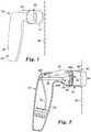
- FIG. 1is a perspective view of a microneedle application device 30 and a skin surface 32.
- the microneedle application device 30can be used to deploy patches that include a microneedle array to a surface, such as to the skin surface 32.
- the device 30has a housing 34 with a gripping portion 36, a trigger 38, and a collar 40.
- One embodiment of a microneedle application device 30is disclosed in U.S. Provisional Patent Application Ser. No. 60/578651 (Attorney Docket No. 59403US002).
- the collar 40defines an outward-facing contact portion 42.
- the collar 40is detachable from the housing 34, and can be disposable or reusable.
- the collar 40is a unitary member of generally cylindrical shape, and contact portion 42 is generally annular in shape.
- the collar 40can have nearly any shape and configuration.
- the collar 40can have a rectangular, triangular, oval, or other shape or combination of shapes.
- the contact portion 42will typically have a shape corresponding to the shape of the collar 40.
- the collar 40need not be unitary, and can be configured to form a number of discrete feet or supports that collectively define the contact portion 42.
- FIG. 2is a cross sectional view of the microneedle application device 30 and a microneedle array patch 52, where the device 30 is positioned against the skin surface 32.
- the device 30includes a support member or actuator.
- the support member or actuatoris a piston 44 having a pad 46 and a shaft 48.
- any type of mechanical, electromechanical, pneumatic, or other type of support member or actuatorcan be used.
- a driver 50 capable of storing energyengages the shaft 48 of the piston 44, and can accelerate the piston 44 to a desired velocity.
- the driver 50may be in the form of a mechanical spring (e.g., a coil spring, leaf spring, etc.), compressed resilient member (e.g., rubber, etc.), compressed fluids (e.g., air, liquids, etc.), piezoelectric structure, electromagnetic structure, etc.
- the collar 40can hold a patch 52, carrying a microneedle array, prior to patch application.
- the microneedle application device 30is positioned with the collar 40 near a desired application site.
- the contact portion 42 of the collar 40is placed in contact with the skin surface 32, and the contact portion 42 defines a target patch application site 54 on the skin surface 32.
- a userwill typically apply some force to the microneedle application device 30 at the gripping portion 36 of the housing 34. At least a portion of that force is generally transmitted through the collar 40 to the skin 32, and that force is referred to as a "pushdown force".
- a “dome” 56is generally created at the target site 54, as the skin 32 responds to the pushdown force.
- This "dome”has parameters of height and firmness. Both of these parameters of the dome are dependent upon the force applied to the applicator during microneedle application device 30 positioning. It is believed that the depth of penetration of a microneedle array is related to the application site, i.e., soft and fatty areas of a body vs. firm muscular areas of a body. Skin characteristics vary across species, and it is believed that particular characteristics of skin will vary across individual test subjects and across selected application sites on individual test subjects. Such variations can affect characteristics of the dome 56.
- a "pushback force”is exerted by the skin 32 in response to the pushdown force. The pushback force is generally directed in a direction directly opposed to the direction of the pushdown force, although specific relationships can be complex and will vary depending on the particular application site.
- a force sensoris coupled to the piston 44 at either end or anywhere along the length of piston 44, for example, at location 58A, 58B and/or 58C (jointly referred to as sensor 58).
- the sensor 58is capable of sensing applied mechanical forces, such as pushback force at the piston 44.
- the sensor 58can be a strain gauge, variable capacitance sensor, or variable resistance sensor.
- the sensor 58comprises a variable resistance member having a semiconducting polymer disposed between conductive layers or grids, where the resistance of the variable resistance member varies according to applied force.
- variable resistance memberis further configured in a voltage divider, which converts the resistance of the member into a voltage signal output that can be measured to detect force applied to the sensor 58.
- a voltage dividerwhich converts the resistance of the member into a voltage signal output that can be measured to detect force applied to the sensor 58.
- An example of such a variable resistance memberis disclosed in U.S. Pat. No. 5.
- Other examples of aspects of such a variable resistance memberare disclosed in U.S. Pat. Nos. 5,904,978 and 5,573,626 .
- Another variable resistance memberis commercially available as an Interlink FSRTM force sensing device available from Interlink Electronics, Inc., Camarillo, CA.
- the piston 44is moveable between a stored position and an extended position. In the stored position, energy is stored in the driver 50, and an actuator 38 secures the piston 44 in its stored position.
- the actuator 38allows an operator to trigger the release of energy stored in the driver 50 to accelerate the piston 44 through the collar 40 and toward the patch 52
- the microneedle application device 30can be used to deliver the microneedle array patch 52 to the skin surface 32, in order to pierce the stratum corneum at the target application site 54 on a patient's skin.
- the patch application devicemay be used to deliver drugs (including any pharmacological agent or agents) through the skin in a variation on transdermal delivery, or to the skin for intradermal or topical treatment, such as vaccination.
- the microneedle array patch 52may be used to pierce the stratum corneum before or after a pharmacological agent is applied to the skin surface in a separate step, thus being used as a pre- or post-treatment step.
- FIG. 3is an enlarged cross sectional view of the collar 40 of the microneedle application device 30 positioned against the skin surface 32.
- the collar 40includes obstructions 70 on an interior portion thereof.
- the obstructions 70are configured to retain patches, such as the patch 52.
- Patch 52includes a backing 72, an adhesive 74 (e.g., a pressure sensitive adhesive), and a microneedle array 76.
- a desired patch application path 78is defined through the collar 40.
- the path 78is substantially perpendicular to a plane in which the microneedle array 76 is retained by the obstructions 70 within the collar 40, and is generally perpendicular to the target application site 54. It is desired that the patch 52 contact the target application site 54 with the patch 52 as close to parallel with the skin surface 32 as possible in order to promote proper microneedle array deployment and proper microneedle penetration of the stratum corneum.
- the patch 52is moved along the patch application path 78.
- This patch movementcan be accomplished by mechanically pushing the patch 52 with the piston 44.
- the microneedle application device 30can use other means for moving the patch 52.
- the patch 52can be moved pneumatically, without contacting a piston.
- FIG. 4Ais a cross sectional side view of the collar 40 of the microneedle application device 30.
- at least one sensoris coupled to a portion of the collar 40 at either end or anywhere along the length of the collar, for example, at location 80A, 80B and/or 80C (jointly referred to as sensor 80).
- An axis 82is defined through the interior of the collar 40.
- the axis 82is generally aligned with a central axis of the piston 44.
- a sensor arranged relative to any of locations 80A-80Cwill sense forces applied to the collar 40, such as pushback force.
- the sensorcan be positioned adjacent one or more actuator structures, such as set screws, feet, struts, etc., that are used to contact and compress the variable resistance member of the sensor 80.
- FIG. 4Bis a schematic side view of portions of a housing 34 and a collar 40 of an alternative embodiment of the microneedle application device.
- the housing 34has an annular protrusion 300 and the collar 40 has an annular protrusion 302.
- the annular protrusions 300 and 302are generally positioned adjacent each other in a spaced relationship.
- a sensor 80 for sensing force at the collar 40is positioned on annular protrusion 300.
- the sensor 80includes a variable resistance layer 304 disposed between a pair of conductive layers 306 and 308.
- a set screw 310is disposed in annular protrusion 302 and has a generally hemispherical contact surface 312 located at one end of the set screw 310.
- the contact surface 312which can be formed of a polymer material, is arranged to face the sensor 80. Adjustment of the set screw 310 allows the contact surface 312 to be positioned in contact with or spaced as much as desired to the sensor 80. Relative movement between the annular protrusions 300 and 302 allows force to be transmitted from the contact portion 312 to the sensor 80 located at a perimeter of the collar 40, which senses associated forces. It will be recognized that additional sensors can be incorporated along the annular protrusions 300 and 302.
- FIGS. 5A-5Care schematic representations of force sensitive regions for alternative sensor arrangements at the contact portion 42 of the collar 40. While FIGS. 5A-5C depict arrangements of sensors along the contact portion 42, corresponding to sensor location 80A in FIG. 4A , similar sensor arrangements are possible regardless of what axial location on the collar 40 the sensors are located. Moreover, further sensor arrangements are contemplated within the scope of the present invention, and can include any number of individual sensors and/or sensor regions.
- FIG. 5Ais a representation of a single sensor region 84A extending in a generally circular shape around the axis 82.
- FIG. 5Bis a four-sensor configuration, with sensor regions 84B-84E arranged in a generally circular shape around the axis 82. The sensor regions 84B-84E are arranged in four generally equal segments that are substantially equally spaced apart, with each sensor region arranged at approximately 90 degree increments around the axis 82.
- FIG. 5Cis a three-sensor configuration, with sensor regions 84F-84H arranged in three generally equal segments that are substantially equally spaced apart, with each sensor region arranged at approximately 120 degree increments around the axis 82.
- the sensor regions 84B-84Hcan correspond to discrete sensor elements or to discretely sensitive regions of one or more sensors. That is, a single sensor may have one or more force sensing elements or discretely sensitive regions.
- the force sensitive regions 84F-84Hmay be small circular sensors that are partially recessed in and evenly spaced around the contact portion 42 of the collar 40.
- Embodiments of a microneedle application device 30 with one or more sensors positioned on the collar 40permit detection of an orientation of the device 30 relative to the skin surface 32. This, in turn, permits feedback generation as to the orientation of the patch 52 relative to the target application site 54, which can be used to predict and characterize the patch application path 78.
- FIG. 6is a cross sectional view of a diagnostic tool 100.
- the housing 34 and many other components of the diagnostic tool 100are shaped to simulate a microneedle application device, such as the microneedle application device 30 of FIGS. 1 and 2 . Similarities permit the diagnostic tool 100 to be used in training and research procedures applicable to use of microneedle application devices.
- the diagnostic tool 100includes a support structure 102 having a shaft 104 fixed within the housing 34 and a pad 106 that extends up to or beyond the contact portion 42 of the collar 40.
- the support structure 102is generally shaped to simulate a microneedle application piston in an extended position.
- the diagnostic tool 100includes a movable piston.
- the diagnostic tool 100further includes a sensor 58 positioned at an interior portion along the support structure 102 and at least one sensor 80 positioned at the contact portion 42 of the collar 40.
- Sensor locations shown in FIG. 6are exemplary, and other sensor arrangements are possible. Moreover, either sensor 58 or 80 could be omitted, and additional sensors at other locations (e.g., on portions of the housing 34) could be included.
- FIGS. 7A-7Care schematic representations of force sensitive regions at a target site for alternative sensor arrangements.
- FIG. 7Ashows a pad sensor region 108, corresponding to sensor 58 on support structure 102 in FIG. 6 , and a single collar sensor region 110A generally surrounding the pad sensor region 108.
- FIG. 7Bshows the pad sensor region 108 and four collar sensor regions 110B-110E generally surrounding the pad sensor region 108.
- the collar sensor regions 110B-110Eare arranged in four generally equal segments that are substantially equally spaced apart, with each sensor region arranged at approximately 90 degree increments around the pad sensor region 108.
- FIG. 7Cshows the pad sensor region 108 and three collar sensor regions 110F-110H generally surrounding the pad sensor region 108.
- the collar sensor regions 110F-110Hare arranged in three generally equal segments that are substantially equally spaced apart, with each sensor region arranged at approximately 120 degree increments around the pad sensor region 108. While the sensor arrangements in FIGS. 7A-7C have been described with respect to the diagnostic tool 100 of FIG. 6 , the sensor arrangements can be equally applied with a microneedle application device, such as that shown and described with respect to FIGS. 1 and 2 .
- any suitable microneedle application devicemay be configured with force sensors as described above.
- suitable microneedle application devicesinclude those described in U. S. Patent Application Publications Nos. US 2002/0091357 A1 , US 2002/0123675 A1 , and US 2002/0087182 ; International Patent Application Nos. PCT/US2005/041870 (Attorney docket no. 60347WO003) and PCT/US2005/041854 (Attorney docket no. 60348WO003), both filed on November 18, 2005, and U. S. Patent Application Serial No. 60/694447 (Attorney docket no. 60874US002) filed on June 27, 2005.
- FIG. 8Ais a block diagram of a digital feedback system 118.
- FIG. 8Ais simplified for clarity. It will be recognized that other components and circuitry can be included, as needed and desired.
- Digital feedback system 118senses forces using piston sensor 58 and one or more collar sensors 80. Signals from the sensors 58 and 80 are supplied through appropriate circuitry to an analog/digital (A/D) converter 120.
- the A/D converter 120is operably connected to a processor 122.
- the processor 122can communicate with memory 124, which can include a database for storing sensed data, and an indicator 126.
- the processorcan be located in a computer that is operably connected to sensors 58 and 80.
- the processor 122can adjust and manipulate raw data sensed by the sensors 58 and 80 as desired for output display or storage in a database.
- the indicator 126can, for instance, inform an operator regarding the relative orientation of the device or tool, and the indication provided can incorporate data from multiple sensors.
- the indicator 126can provide an indication in numerous forms, be they visual, audible, tactile, etc.
- the system 118can include a lockout mechanism, such as lockout 128.
- the lockout 128can prevent an operator from applying a patch unless magnitude of a sensed applied force is within a preferred range. Such a preferred range can consist of a single force value for sensor configurations such as that shown and described with respect to FIG. 5A or with respect to multiple force values obtained from multiple sensor arrangements such as those shown and described with respect to FIGS. 5B, 5C, 7A, 7B and 7C .
- the lockout 128can permit patch application only when the device or tool is in a particular desired position.
- the lockout 128can prevent patch application by preventing the trigger 38 (shown in FIGS. 1 and 2 ) from being actuated.
- the sensor(s)can provide direct feedback to the trigger 38, thereby activating the trigger only when the tool has been placed into a particular desired position.
- components of the system 118can be wholly contained on or within a tool, or one or more components can be located externally.
- Components of the system 118can be connected by a physical or wireless (e.g., radio wave) connection, and can include transmission of data and signals over a network or the Internet.
- FIG. 8Bis a block diagram of an analog feedback system 130, which includes a piston sensor 58 electrically connected to a limiter/filter 132, and an indicator 126.
- the limiter/filter 132can provide bandwidth limiting (e.g., with low and/or high pass filters), linearization of sensed force responses, and gain adjustment.
- the analog feedback system 130can include other components and circuitry, not shown in FIG. 8B for clarity, as needed and desired.
- one or more additional sensorse.g., collar sensors 80 as shown in FIG. 8A
- components of the system 130can be wholly contained on or within a tool, or one or more components can be located externally.
- any combination of analog and digital circuitrycan be implemented as desired.
- FIGS. 9A-9Cillustrate exemplary indicators for displaying sensed force and/or tool orientation data according to the present invention.
- FIG. 9Ashows an indicator 126A having a readout display 150 for showing quantitative force output sensed, and a pair of visual meters 152 and 154.
- the indicator 126Acould indicate an output derived from any sensor on a tool, such as sensors 58 and 80 shown and described above.
- the readout display 150is a digital display, such as a 3 1/2 digit liquid crystal display (LCD).
- the readout display 150can be any type of digital or analog display, such as a dial.
- FIG. 9Ashows an indicator 126A having a readout display 150 for showing quantitative force output sensed, and a pair of visual meters 152 and 154.
- the indicator 126Acould indicate an output derived from any sensor on a tool, such as sensors 58 and 80 shown and described above.
- the readout display 150is a digital display, such as a 3 1/2 digit liquid crystal display (LCD).
- the pair of visual meters 152 and 154are two rows of light emitting diodes (LEDs), with each row having three color regions 156, 158 and 160.
- the color regions 156, 158 and 160can correspond to green, yellow and red LEDs, respectively.
- One meter, for example meter 152can provide a dynamic indication of force sensed at a collar of a tool (see, e.g., FIG. 5A ), with more LEDs lighting from left to right to indicate greater force sensed.
- Meter 152can also hold a maximum value for a desire period and then decay.
- the other meteri.e., meter 154) can indicate average force applied.
- the readout display 150 and the visual meters 152 and 154can be used on a real-time basis to assess the positioning of a tool relative to a target surface (e.g., the pushdown force applied by an operator), as well as to assess the suitability of a selected target site for microneedle application.
- a target surfacee.g., the pushdown force applied by an operator
- the indicator 126Acan provide an indication of force sensed at multiple locations.
- meter 152can indicate force sensed at a collar of a tool (see, e.g., sensor region 108 of FIG. 7A ) and meter 154 can indicate force sensed at a support member or actuator of a tool (see, e.g., sensor region 110A of FIG. 7A ).
- the visual meterscan have other shapes and arrangements (e.g., starburst shape, etc.) as desired for the particular context.
- additional readout displayscan be included with the indicator 126A. Each readout display can correspond to data for a particular sensor, or can correspond to processed data (e.g., averages, multiple sensor data trend data, etc.).
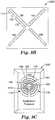
- FIG. 9Bshows an indicator 126B having four visual meters 162, 164, 166, and 168 generally arranged in an "X" shape.
- Each visual meter 162-68can be color coded into multiple regions, with each region having nearly any color.
- Visual meter 162is shown with a green region 170, a yellow region 172 and a red region 174, and the other visual meters 164, 166 and 168 can be color coded in the same manner.
- the visual meters 164, 166 and 168can operate much in the same manner as described with respect to indicator 126A above.
- the X-shaped arrangement of the visual meters 162, 164, 166 and 168can indicate force sensed from multiple sensors, for instance, each visual meter 162, 164, 166 and 168 can correspond to a sensing region 84B-84E as shown in FIG. 5B .
- Other arrangements of the visual meters 162, 164, 166 and 168are contemplated, and will vary according to preference and factors such as the number and arrangement of sensors on the corresponding tool.
- Indicator 126Bcan be used to indicate the orientation of a tool relative to a surface, by indicating whether forces are evenly distributed about a portion of the tool (e.g., about the collar of a microneedle application device or, more specifically, about an annular collar of such a device). When provided on a real-time basis, such an indication can be used, by an operator, to adjust the orientation of the tool.
- the indicator 126Bcan be used to adjust the magnitude of force applied to the tool by the operator.
- FIG. 9Cshows an indicator 126C having a binary display 172 and three visual meters 174, 176 and 178 located around the binary display 172.
- the arrangement of the visual meters 174, 176 and 178can indicate force sensed from multiple sensors, for instance, each visual meter 174, 176 and 178 can correspond to sensor arrangements shown in FIGS. 5C and 7C .
- Each visual meter 174, 176 and 178can have color coded regions 180, 182, 184, 186 and 188 that are, from the innermost region to the outermost region, red (180), yellow (182), green (184), yellow (186), and red (188).
- the green region 184can indicate that force sensed is in a desirable range for microneedle application.
- the inner regions 180 (red) and 182 (yellow)can indicate insufficient force, and the outer regions 186 (yellow) and 188 (red) can indicate excessive force.
- the binary display 172can indicate whether the force and/or orientation of a tool is proper or improper for microneedle application, and the ultimate binary output can accompany an analysis of a number of different force and orientation factors.
- indicatorscan provide auditory output, such as from a sound generator (buzz, squeal, click, etc.) or enunciator (e.g., a voice output).
- the indicatorcan also provide an indication of force by varying the intensity of an output (e.g., light or sound intensity).
- the indicatorcan be directly connected to the tool, or can be remotely located.
- the indicatorcan be a display on a computer.
- outputscan be processed for display by software, such as commercially available software packages like EXCEL spreadsheet software from Microsoft Corp., Redmond, WA, MATLAB software from The MathWorks, Inc., Natick, MA, and data acquisition and analysis software (e.g., LabVIEW) from National Instruments Corporation, Austin, TX.
- the ranges and limits of indicatorscan be set according to a value meaningful for the particular application, for instance, at a value that ensures a high degree of confidence for drug delivery by microneedle arrays. Specific values will vary depending on factors such as application device configuration, microneedle array configuration, molecules to be delivered, etc.
- FIG. 10Ais a graph 200 with a curve 202 of force sensed at a single sensor located at a collar of a tool (see, e.g., FIG. 5A ) versus time as the collar is positioned against a skin surface (see, e.g., FIG. 2 ), and a range 204 of forces acceptable for microneedle application.
- sensed forceincreases initially, then produces a dynamic response as an operator adjusts applied force while observing feedback indication(s), and then drop as the collar is moved away from the skin surface.
- Regions 206, 208 and 210represent time periods when the curve 202 falls within the range 204, and correspond to one or more proper conditions for microneedle application.
- FIG. 10Bis a graph 220 with four curves 222, 224, 226 and 228 representing force sensed at four sensors located at a collar of a tool (see, e.g., FIG. 5B ) versus time as the collar is positioned and adjusted against a skin surface (see, e.g., FIG. 2 ), and a range 230 of forces acceptable for microneedle application. As shown in FIG.
- a region 232represents a time period when all of the curves 222, 224, 226 and 228 fall within the range 230, and corresponds to one or more proper conditions for microneedle application.
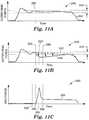
- FIG. 11Ais a graph 240 with a curve 242 representing force sensed at a single sensor located at a collar of a tool (see, e.g., sensor region 110A in FIG. 7A ) versus time as the collar is positioned and adjusted against a skin surface (see, e.g., FIG. 2 ), and where no piston is actuated.
- a range 204 of forces acceptable for microneedle applicationis shown.
- FIG. 11Bis a graph 246 with a curve 248 representing force sensed at a collar (see, e.g., sensor region 110A in FIG. 7A ) versus time as the collar is positioned and adjusted against a skin surface.
- Patch applicationis triggered at time 250, while the curve 248 falls in the range 244, and then a pad of a piston of the applicator reaches the skin surface at time 252.
- the collar and the pistonare sharing forces between the applicator device and the skin surface.
- time 256the forces between the applicator device and the skin surface are approaching equilibrium. As shown in FIG.
- FIG. 11Cis a graph 260 with a curve 262 representing force sensed at the pad of the piston (see, e.g., sensor region 108 in FIG. 7A ) versus time during the operation shown in FIG. 11B .
- the curve 262increases from time 252 to time 254 after the pad initially reaches the skin surface, and then decreases from time 254 to time 256 as forces are shared between the piston and the collar.
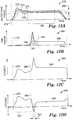
- FIG. 12Ais a graph 270 with four curves 272, 274, 276 and 278 representing force sensed by four sensors located at a collar (see, e.g., sensor regions 110B, 110C, 110D and 110E in FIG. 7B ) versus time as the collar is positioned and adjusted against a skin surface beginning at time 279, and where no piston is actuated.
- a range 280 of forces acceptable for microneedle applicationis shown.
- a region 282represents a time period when all of the curves 272, 274, 276 and 278 fall within the range 280, and corresponds to one or more proper conditions for microneedle application.
- FIG. 12Bis a graph 284 with a curve 286 representing force sensed at a pad of a piston (see, e.g., sensor region 108 in FIG. 7B ) versus time when the collar is positioned and adjusted against the skin surface. Patch application is triggered and the pad of the piston reaches the skin surface at time 288. Force sensed at the pad approaches equilibrium at time 290. An area 291 is created under curve 286 between times 288 and 290.
- FIG. 12Cis a graph 292 with a curve 294 representing a sum ( ⁇ ) of an average force at the collar (e.g., the sum of curves 272, 274, 276 and 278 divided by four) and the force at the pad of the piston (curve 286), as depicted in FIGS. 12A and 12B , versus time.
- ⁇an average force at the collar
- curve 286the force at the pad of the piston
- FIG. 12Dis a graph 296 with a curve 298 representing a force difference ( ⁇ ) between the average force at the collar (e.g., the sum of curves 272, 274, 276 and 278 divided by four), minus the force at the pad of the piston, as depicted by curve 286 in FIG. 12B , versus time.
- the values of curve 298are negative, and reach a peak negative value 302. It is possible to correlate a time interval (e.g., the time interval 300) where the force difference ⁇ of graph 296 is negative with a particular assessment of patch application.
- a particular time interval where the force differential is negativemay be correlated with a "good", desirable or proper patch application procedure and an appropriate output produced for recordation or indication to an operator. Further analysis of sensed data can be based upon magnitude, time (duration), area above or below curves, and other criteria.
- the particular ranges 204, 230, 244, 280 of acceptable forces for microneedle applicationmay vary and might depend on a number of factors including, but not limited to, the size, number, and shape of the microneedles, the type and amount, if any, of pharmacological agent being applied, the type and location of the skin surface, and the desired therapeutic response.
- the present inventionpermits more consistent microneedle array application by providing feedback as to application parameters. For instance, where sensors are provided on both a collar and a piston of a microneedle application device, pushback force can be sensed and measured in relation to skin doming at a specific target site. In addition, for example, the recoil effect, if any, during patch application can be sensed and assessed.
- Sensed datacan assist in real-time site selection and patch application procedures. Real-time feedback allows an operator to obtain reliable characterizations of application procedure parameters without relying on muscle memory or other training-dependent factors for consistent and reliable patch application. Sensed data can also be used, in some situation, to adjust forces applied to move a patch toward a target application site, such as by selecting an appropriate applicator or in conjunction with adjusting a variable force driver.
- the present inventionprovides the ability to measure and diagnose parameters associated with a particular target site for microneedle application as they directly apply to the chosen application device (or tool). This is advantageous over other devices as it allows for characterization of an application site by determining the specific site variable of skin pushback force relative to applied force.
- the present inventioncan also be used to assess the angle of application, i.e., the orientation of the tool, to assist the user in positioning the tool perpendicular to the target site by assuring that generally even pressure is applied over three or more force sensor regions at a contact portion of the tool.
- the present inventionhas advantages for use in pre-clinical testing on non-human animals in order to better correlate research data to human testing and other subsequent application contexts.
- the present inventionhas advantages over current technology in its ability to assess a site specifically for microneedle application.
- the specified advantagesshould not be considered limiting in any way to the overall scope or utility of the invention.
Landscapes
- Health & Medical Sciences (AREA)
- Life Sciences & Earth Sciences (AREA)
- Engineering & Computer Science (AREA)
- General Health & Medical Sciences (AREA)
- Veterinary Medicine (AREA)
- Biomedical Technology (AREA)
- Heart & Thoracic Surgery (AREA)
- Physics & Mathematics (AREA)
- Medical Informatics (AREA)
- Animal Behavior & Ethology (AREA)
- Public Health (AREA)
- Dermatology (AREA)
- Anesthesiology (AREA)
- Hematology (AREA)
- Optics & Photonics (AREA)
- Biophysics (AREA)
- Pathology (AREA)
- Molecular Biology (AREA)
- Surgery (AREA)
- Media Introduction/Drainage Providing Device (AREA)
Description
- The present application claims priority to
U.S. Provisional Application Serial No. 60/669,133 , filed on April 7. - The present invention relates to a system for feedback sensing. Such a device is disclosed in the
US6656147 . More particularly, the present invention relates to feedback sensing provided with tools for assisting with microneedle application procedures. - Only a limited number of molecules with demonstrated therapeutic value can be transported through the skin, even with the use of approved chemical enhancers. The main barrier to transport of molecules through the skin is the stratum corneum (the outermost layer of the skin).
- Devices including arrays of relatively small structures, sometimes referred to as microneedles or micro-pins, have been disclosed for use in connection with the delivery of therapeutic agents and other substances through the skin and other surfaces. The devices are typically pressed against the skin in an effort to pierce the stratum corneum such that the therapeutic agents and other substances can pass through that layer and into the tissues below.
- Microneedle arrays can be used in conjunction with an applicator device capable of being used a number of different times. The applicator device can include a removable collar for holding the microneedle array prior to deployment. The collar can be reusable or disposable. The microneedle arrays are generally used once and then discarded. The arrays are typically manufactured in a flat sheet-like configuration and temporarily attached to the applicator device using, for example, an adhesive.
- Devices exist in the market for making measurement of skin properties, such as Cutometers (skin elasticity), Reviscometers (skin construction), and contact Tonometers (time to rebound from a given deflection), but the suitability of these measurements for use in effectively characterizing microneedle application sites is not known.
- Research involving microneedle application may be conducted at application sites on different skin surfaces. For instance, tests may be performed involving microneedle arrays applied to particular skin target areas (e.g., forearms, buttocks, biceps, etc.) of a selected sample of like persons or to persons differing in some way (e.g., by age, race, gender, etc.) or to the skin of different species of test subjects.
- The process of consistent use of microneedle application technology presents numerous challenges. Operation of microneedle applicator devices by operators, such as healthcare providers, can be problematic. Operator error, for example, can result in improper microneedle array deployment, which can undermine desired molecule transport. It is believed that proper applicator device positioning can affect microneedle array deployment. However, it is difficult to help ensure proper applicator device positioning. Additional problems are faced in research contexts. Variations across different application sites present difficulties in gathering reliable data from research tests, and in reliably applying collected research data to other contexts.
- In one aspect, the present invention relates to a microneedle application device as further disclosed in
claim 1, for moving a microneedle array toward a target skin location includes a feedback sensor. The feedback sensor is operably connected to the microneedle application device, and is capable of generating an output corresponding to forces between the target skin location and the microneedle application device. - The present disclosure also relates to a method of microneedle application. The method comprises providing a microneedle applicator device, providing a microneedle array that is initially mounted to the microneedle applicator device, positioning a locating portion of the microneedle applicator device in contact with skin to substantially define a target application site on the skin for application of the microneedle array, sensing a force between the target application site and a first portion of the microneedle applicator device, positioning the microneedle applicator device such that the microneedle array can be moved into contact with the skin along a path that is substantially orthogonal relative to the target application site, and moving the microneedle array toward the target application site.
- The present disclosure also relates to a method of positioning a tool for assisting with microneedle application procedures. The method comprises placing the tool in contact with a target site, and sensing a pushback force of the target site against the tool.
- In another aspect, the present invention relates to an applicator system as further disclosed in claim 2 including a microneedle application device and a force sensing element. The microneedle application device has a portion adapted for skin contact at least prior to microneedle application. The force sensing element is capable of sensing force between the portion of the microneedle applicator adapted for skin contact and a target application site.
- The present disclosure also relates to a tool for sensing forces between the tool and a skin surface. The tool includes a housing having a force application portion, a contact portion, a support, and a sensor. The contact portion is supported by the housing, and is capable of contacting the skin surface to substantially define a target location. The support is supported by the housing, and is capable of reaching the target location. The sensor is disposed between the target location and a first portion of the tool, and is capable of sensing force.
FIG. 1 is a perspective view of a microneedle application device and a target skin surface.FIG. 2 is a cross sectional side view of the microneedle application device and a microneedle array patch, where the microneedle application device is positioned against the target skin surface.FIG. 3 is an enlarged cross sectional side view of a portion of the microneedle application device positioned against the target skin surface.FIG. 4A is a cross sectional side view of a portion of the microneedle application device.FIG. 4B is a schematic side view of a portion of an alternative embodiment of the microneedle application device.FIGS. 5A-5C are schematic representations of force sensitive regions at a target application site for alternative collar sensor arrangements.FIG. 6 is a cross sectional side view of a diagnostic tool.FIGS. 7A-7C are schematic representations of force sensitive regions at a target site for alternative sensor arrangements.FIG. 8A is a block diagram of a digital feedback system.FIG. 8B is a block diagram of an analog feedback system.FIGS. 9A-9C illustrate alternative indicators for displaying sensed force and/or tool orientation data according to the present invention.FIG. 10A is a graph of force sensed at a single sensor coupled to a collar of a tool versus time as the collar is positioned and adjusted against a skin surface, and a range of forces acceptable for microneedle application.FIG. 10B is a graph of force sensed at four sensors coupled to a collar of a tool versus time as the collar is positioned and adjusted against a skin surface, and a range of forces acceptable for microneedle application.FIG. 11A is a graph of force sensed at a single sensor at a collar versus time as the collar is positioned and adjusted against a skin surface, and where no piston is actuated.FIG. 11B is a graph of force sensed at a collar versus time as the collar is positioned and adjusted against a skin surface, and where a piston is actuated to eventually reach the skin surface.FIG. 11C is a graph of force sensed at a pad of the piston versus time as the collar is positioned against the skin surface, and where the piston is actuated to eventually reach the skin surface as inFIG. 11B .FIG. 12A is a graph of force sensed by four sensors coupled to a collar versus time, when the collar is positioned and adjusted against a skin surface, and where no piston is actuated.FIG. 12B is a graph of force sensed at a pad of a piston versus time when the collar is positioned against the skin surface, and where the piston is actuated to eventually reach the skin surface.FIG. 12C is a graph of a sum of forces at the collar and the pad of the piston, as depicted inFIGS. 12A and 12B , versus time.FIG. 12D is a graph of the force at the collar, as depicted inFIG. 12A , minus the force at the pad of the piston, as depicted inFIG. 12B , versus time.- While the above-identified drawing figures set forth several embodiments of the invention, other embodiments are also contemplated, as noted in the discussion. In all cases, this disclosure presents the invention by way of representation and not limitation. It should be understood that numerous other modifications and embodiments can be devised by those skilled in the art, which fall within the scope and spirit of the principles of the invention. The figures may not be drawn to scale. Like reference numbers have been used throughout the figures to denote like parts.
- The present invention relates to providing feedback for tools such as microneedle array application devices, as well as diagnostic instruments used in microneedle array application research and training (which may be configured to mimic or simulate typical microneedle application devices). One or more sensors are provided on the tool for sensing forces between the tool and a surface (such as a target skin surface) against which the tool is positioned. An output of the sensed forces can be provided. In some embodiments with multiple sensors, feedback provided according to the present invention permits an indication of how desirably orientated the tool is relative to the surface against which it is positioned. In addition, the present invention can be used for determining ideal locations on the body for application of microneedles.
- Aspects of the present invention can be used in conjunction with a variety of tools, though particular advantages are provided for patch application devices. Patches can be used for transdermal delivery of molecules, and can carry microneedle arrays, which have utility for the delivery of large molecules that are ordinarily difficult to deliver by passive transdermal delivery. As used herein, "array" refers to the medical devices described herein that include one or more structures capable of piercing the stratum corneum to facilitate the transdermal delivery of therapeutic agents or the sampling of fluids through or to the skin. "Microstructure," "microneedle" or "microarray" refers to the specific microscopic structures associated with the array that are capable of piercing the stratum corneum to facilitate the transdermal delivery of therapeutic agents or the sampling of fluids through the skin. By way of example, microstructures can include needle or needle-like structures as well as other structures capable of piercing the stratum corneum.
FIG. 1 is a perspective view of amicroneedle application device 30 and askin surface 32. Themicroneedle application device 30 can be used to deploy patches that include a microneedle array to a surface, such as to theskin surface 32. Thedevice 30 has ahousing 34 with a grippingportion 36, atrigger 38, and acollar 40. One embodiment of amicroneedle application device 30 is disclosed inU.S. Provisional Patent Application Ser. No. 60/578651 (Attorney Docket No. 59403US002).- The
collar 40 defines an outward-facingcontact portion 42. In one embodiment, thecollar 40 is detachable from thehousing 34, and can be disposable or reusable. As shown inFIG. 1 , thecollar 40 is a unitary member of generally cylindrical shape, andcontact portion 42 is generally annular in shape. In further embodiments, thecollar 40 can have nearly any shape and configuration. For example, thecollar 40 can have a rectangular, triangular, oval, or other shape or combination of shapes. Thecontact portion 42 will typically have a shape corresponding to the shape of thecollar 40. In addition, thecollar 40 need not be unitary, and can be configured to form a number of discrete feet or supports that collectively define thecontact portion 42. FIG. 2 is a cross sectional view of themicroneedle application device 30 and amicroneedle array patch 52, where thedevice 30 is positioned against theskin surface 32. Thedevice 30 includes a support member or actuator. In the embodiment shown inFIG. 2 , the support member or actuator is apiston 44 having apad 46 and ashaft 48. In alternative embodiments, any type of mechanical, electromechanical, pneumatic, or other type of support member or actuator can be used.- A
driver 50 capable of storing energy engages theshaft 48 of thepiston 44, and can accelerate thepiston 44 to a desired velocity. For example, thedriver 50 may be in the form of a mechanical spring (e.g., a coil spring, leaf spring, etc.), compressed resilient member (e.g., rubber, etc.), compressed fluids (e.g., air, liquids, etc.), piezoelectric structure, electromagnetic structure, etc. Thecollar 40 can hold apatch 52, carrying a microneedle array, prior to patch application. - In operation, the
microneedle application device 30 is positioned with thecollar 40 near a desired application site. Thecontact portion 42 of thecollar 40 is placed in contact with theskin surface 32, and thecontact portion 42 defines a targetpatch application site 54 on theskin surface 32. A user will typically apply some force to themicroneedle application device 30 at the grippingportion 36 of thehousing 34. At least a portion of that force is generally transmitted through thecollar 40 to theskin 32, and that force is referred to as a "pushdown force". - A "dome" 56 is generally created at the
target site 54, as theskin 32 responds to the pushdown force. This "dome" has parameters of height and firmness. Both of these parameters of the dome are dependent upon the force applied to the applicator duringmicroneedle application device 30 positioning. It is believed that the depth of penetration of a microneedle array is related to the application site, i.e., soft and fatty areas of a body vs. firm muscular areas of a body. Skin characteristics vary across species, and it is believed that particular characteristics of skin will vary across individual test subjects and across selected application sites on individual test subjects. Such variations can affect characteristics of thedome 56. In addition, a "pushback force" is exerted by theskin 32 in response to the pushdown force. The pushback force is generally directed in a direction directly opposed to the direction of the pushdown force, although specific relationships can be complex and will vary depending on the particular application site. - In the embodiment shown in
FIG. 2 , a force sensor is coupled to thepiston 44 at either end or anywhere along the length ofpiston 44, for example, atlocation sensor 58 is capable of sensing applied mechanical forces, such as pushback force at thepiston 44. Thesensor 58 can be a strain gauge, variable capacitance sensor, or variable resistance sensor. In one embodiment, thesensor 58 comprises a variable resistance member having a semiconducting polymer disposed between conductive layers or grids, where the resistance of the variable resistance member varies according to applied force. The variable resistance member is further configured in a voltage divider, which converts the resistance of the member into a voltage signal output that can be measured to detect force applied to thesensor 58. An example of such a variable resistance member is disclosed in U.S. Pat. No. 5. Other examples of aspects of such a variable resistance member are disclosed inU.S. Pat. Nos. 5,904,978 and5,573,626 . Another variable resistance member is commercially available as an Interlink FSR™ force sensing device available from Interlink Electronics, Inc., Camarillo, CA. - In the
microneedle application device 30, thepiston 44 is moveable between a stored position and an extended position. In the stored position, energy is stored in thedriver 50, and anactuator 38 secures thepiston 44 in its stored position. Theactuator 38 allows an operator to trigger the release of energy stored in thedriver 50 to accelerate thepiston 44 through thecollar 40 and toward thepatch 52 - The
microneedle application device 30 can be used to deliver themicroneedle array patch 52 to theskin surface 32, in order to pierce the stratum corneum at thetarget application site 54 on a patient's skin. For example, the patch application device may be used to deliver drugs (including any pharmacological agent or agents) through the skin in a variation on transdermal delivery, or to the skin for intradermal or topical treatment, such as vaccination. Alternatively, themicroneedle array patch 52 may be used to pierce the stratum corneum before or after a pharmacological agent is applied to the skin surface in a separate step, thus being used as a pre- or post-treatment step. FIG. 3 is an enlarged cross sectional view of thecollar 40 of themicroneedle application device 30 positioned against theskin surface 32. Thecollar 40 includesobstructions 70 on an interior portion thereof. Theobstructions 70 are configured to retain patches, such as thepatch 52.Patch 52 includes abacking 72, an adhesive 74 (e.g., a pressure sensitive adhesive), and amicroneedle array 76.- A desired
patch application path 78 is defined through thecollar 40. Thepath 78 is substantially perpendicular to a plane in which themicroneedle array 76 is retained by theobstructions 70 within thecollar 40, and is generally perpendicular to thetarget application site 54. It is desired that thepatch 52 contact thetarget application site 54 with thepatch 52 as close to parallel with theskin surface 32 as possible in order to promote proper microneedle array deployment and proper microneedle penetration of the stratum corneum. - In operation, the
patch 52 is moved along thepatch application path 78. This patch movement can be accomplished by mechanically pushing thepatch 52 with thepiston 44. In alternative embodiments, themicroneedle application device 30 can use other means for moving thepatch 52. For example, thepatch 52 can be moved pneumatically, without contacting a piston. FIG. 4A is a cross sectional side view of thecollar 40 of themicroneedle application device 30. As shown inFIG. 4A , at least one sensor is coupled to a portion of thecollar 40 at either end or anywhere along the length of the collar, for example, atlocation 80A, 80B and/or 80C (jointly referred to as sensor 80). Anaxis 82 is defined through the interior of thecollar 40. In embodiments of themicroneedle application device 30 using a piston to move thepatch 52, theaxis 82 is generally aligned with a central axis of thepiston 44. A sensor arranged relative to any of locations 80A-80C will sense forces applied to thecollar 40, such as pushback force. In embodiments where variable resistance sensors are utilized, the sensor can be positioned adjacent one or more actuator structures, such as set screws, feet, struts, etc., that are used to contact and compress the variable resistance member of thesensor 80.FIG. 4B is a schematic side view of portions of ahousing 34 and acollar 40 of an alternative embodiment of the microneedle application device. Thehousing 34 has anannular protrusion 300 and thecollar 40 has anannular protrusion 302. Theannular protrusions sensor 80 for sensing force at thecollar 40 is positioned onannular protrusion 300. Thesensor 80 includes avariable resistance layer 304 disposed between a pair ofconductive layers set screw 310 is disposed inannular protrusion 302 and has a generallyhemispherical contact surface 312 located at one end of theset screw 310. Thecontact surface 312, which can be formed of a polymer material, is arranged to face thesensor 80. Adjustment of theset screw 310 allows thecontact surface 312 to be positioned in contact with or spaced as much as desired to thesensor 80. Relative movement between theannular protrusions contact portion 312 to thesensor 80 located at a perimeter of thecollar 40, which senses associated forces. It will be recognized that additional sensors can be incorporated along theannular protrusions FIGS. 5A-5C are schematic representations of force sensitive regions for alternative sensor arrangements at thecontact portion 42 of thecollar 40. WhileFIGS. 5A-5C depict arrangements of sensors along thecontact portion 42, corresponding to sensor location 80A inFIG. 4A , similar sensor arrangements are possible regardless of what axial location on thecollar 40 the sensors are located. Moreover, further sensor arrangements are contemplated within the scope of the present invention, and can include any number of individual sensors and/or sensor regions.FIG. 5A is a representation of asingle sensor region 84A extending in a generally circular shape around theaxis 82.FIG. 5B is a four-sensor configuration, withsensor regions 84B-84E arranged in a generally circular shape around theaxis 82. Thesensor regions 84B-84E are arranged in four generally equal segments that are substantially equally spaced apart, with each sensor region arranged at approximately 90 degree increments around theaxis 82.FIG. 5C is a three-sensor configuration, withsensor regions 84F-84H arranged in three generally equal segments that are substantially equally spaced apart, with each sensor region arranged at approximately 120 degree increments around theaxis 82. It will be understood that thesensor regions 84B-84H can correspond to discrete sensor elements or to discretely sensitive regions of one or more sensors. That is, a single sensor may have one or more force sensing elements or discretely sensitive regions. In one embodiment, (not shown) the forcesensitive regions 84F-84H may be small circular sensors that are partially recessed in and evenly spaced around thecontact portion 42 of thecollar 40. Embodiments of amicroneedle application device 30 with one or more sensors positioned on thecollar 40 permit detection of an orientation of thedevice 30 relative to theskin surface 32. This, in turn, permits feedback generation as to the orientation of thepatch 52 relative to thetarget application site 54, which can be used to predict and characterize thepatch application path 78. For example, looking to the sensor arrangement shown inFIG. 5B , larger forces sensed atsensor regions sensor regions collar 40. Such unequal force distribution can indicate that force applied to themicroneedle application device 30 by an operator is skewed, and could lead to undesirable and improper patch application.- While feedback provided according to the present invention is useful at the time of microneedle application, such feedback is also useful in broader contexts, including training and research settings that may precede or follow patch application. For instance, feedback sensing can be accomplished with purely diagnostic tools.
FIG. 6 is a cross sectional view of adiagnostic tool 100. In the embodiment shown inFIG. 6 , thehousing 34 and many other components of thediagnostic tool 100 are shaped to simulate a microneedle application device, such as themicroneedle application device 30 ofFIGS. 1 and 2 . Similarities permit thediagnostic tool 100 to be used in training and research procedures applicable to use of microneedle application devices. - As shown in
FIG. 6 , thediagnostic tool 100 includes asupport structure 102 having ashaft 104 fixed within thehousing 34 and apad 106 that extends up to or beyond thecontact portion 42 of thecollar 40. Thesupport structure 102 is generally shaped to simulate a microneedle application piston in an extended position. In alternative embodiments, thediagnostic tool 100 includes a movable piston. - The
diagnostic tool 100 further includes asensor 58 positioned at an interior portion along thesupport structure 102 and at least onesensor 80 positioned at thecontact portion 42 of thecollar 40. Sensor locations shown inFIG. 6 are exemplary, and other sensor arrangements are possible. Moreover, eithersensor FIGS. 7A-7C are schematic representations of force sensitive regions at a target site for alternative sensor arrangements.FIG. 7A shows apad sensor region 108, corresponding tosensor 58 onsupport structure 102 inFIG. 6 , and a singlecollar sensor region 110A generally surrounding thepad sensor region 108.FIG. 7B shows thepad sensor region 108 and fourcollar sensor regions 110B-110E generally surrounding thepad sensor region 108. Thecollar sensor regions 110B-110E are arranged in four generally equal segments that are substantially equally spaced apart, with each sensor region arranged at approximately 90 degree increments around thepad sensor region 108.FIG. 7C shows thepad sensor region 108 and threecollar sensor regions 110F-110H generally surrounding thepad sensor region 108. Thecollar sensor regions 110F-110H are arranged in three generally equal segments that are substantially equally spaced apart, with each sensor region arranged at approximately 120 degree increments around thepad sensor region 108. While the sensor arrangements inFIGS. 7A-7C have been described with respect to thediagnostic tool 100 ofFIG. 6 , the sensor arrangements can be equally applied with a microneedle application device, such as that shown and described with respect toFIGS. 1 and 2 .- Although various embodiments are illustrated in the
FIGS. 1-7 , it should be appreciated that any suitable microneedle application device may be configured with force sensors as described above. For example, suitable microneedle application devices include those described in U. S. Patent Application Publications Nos.US 2002/0091357 A1 ,US 2002/0123675 A1 , andUS 2002/0087182 ; International Patent Application Nos.PCT/US2005/041870 (Attorney docket no. 60347WO003) andPCT/US2005/041854 (Attorney docket no. 60348WO003), both filed on November 18, 2005, andU. S. Patent Application Serial No. 60/694447 FIG. 8A is a block diagram of adigital feedback system 118.FIG. 8A is simplified for clarity. It will be recognized that other components and circuitry can be included, as needed and desired.Digital feedback system 118 senses forces usingpiston sensor 58 and one ormore collar sensors 80. Signals from thesensors converter 120. The A/D converter 120 is operably connected to aprocessor 122. Theprocessor 122 can communicate withmemory 124, which can include a database for storing sensed data, and anindicator 126. The processor can be located in a computer that is operably connected tosensors processor 122 can adjust and manipulate raw data sensed by thesensors indicator 126 can, for instance, inform an operator regarding the relative orientation of the device or tool, and the indication provided can incorporate data from multiple sensors. Theindicator 126 can provide an indication in numerous forms, be they visual, audible, tactile, etc.- In addition, the
system 118 can include a lockout mechanism, such aslockout 128. Thelockout 128 can prevent an operator from applying a patch unless magnitude of a sensed applied force is within a preferred range. Such a preferred range can consist of a single force value for sensor configurations such as that shown and described with respect toFIG. 5A or with respect to multiple force values obtained from multiple sensor arrangements such as those shown and described with respect toFIGS. 5B, 5C, 7A, 7B and 7C . Alternatively or in addition, thelockout 128 can permit patch application only when the device or tool is in a particular desired position. In one embodiment, thelockout 128 can prevent patch application by preventing the trigger 38 (shown inFIGS. 1 and 2 ) from being actuated. In an alternative embodiment, the sensor(s) can provide direct feedback to thetrigger 38, thereby activating the trigger only when the tool has been placed into a particular desired position. - It will be recognized that components of the
system 118 can be wholly contained on or within a tool, or one or more components can be located externally. Components of thesystem 118 can be connected by a physical or wireless (e.g., radio wave) connection, and can include transmission of data and signals over a network or the Internet. FIG. 8B is a block diagram of ananalog feedback system 130, which includes apiston sensor 58 electrically connected to a limiter/filter 132, and anindicator 126. The limiter/filter 132 can provide bandwidth limiting (e.g., with low and/or high pass filters), linearization of sensed force responses, and gain adjustment. Theanalog feedback system 130 can include other components and circuitry, not shown inFIG. 8B for clarity, as needed and desired. In further embodiments, one or more additional sensors (e.g.,collar sensors 80 as shown inFIG. 8A ) can also be electrically connected to the limiter/filter 132. Additionally, it will be recognized that components of thesystem 130 can be wholly contained on or within a tool, or one or more components can be located externally. Moreover, in alternative embodiments, any combination of analog and digital circuitry can be implemented as desired.FIGS. 9A-9C illustrate exemplary indicators for displaying sensed force and/or tool orientation data according to the present invention.FIG. 9A shows anindicator 126A having areadout display 150 for showing quantitative force output sensed, and a pair ofvisual meters indicator 126A could indicate an output derived from any sensor on a tool, such assensors FIG. 9A , thereadout display 150 is a digital display, such as a 3 1/2 digit liquid crystal display (LCD). In further embodiments, thereadout display 150 can be any type of digital or analog display, such as a dial. In the embodiment shown inFIG. 9A , the pair ofvisual meters color regions color regions example meter 152, can provide a dynamic indication of force sensed at a collar of a tool (see, e.g.,FIG. 5A ), with more LEDs lighting from left to right to indicate greater force sensed.Meter 152 can also hold a maximum value for a desire period and then decay. The other meter (i.e., meter 154) can indicate average force applied. Thereadout display 150 and thevisual meters - In an alternative embodiment, the
indicator 126A can provide an indication of force sensed at multiple locations. For instance,meter 152 can indicate force sensed at a collar of a tool (see, e.g.,sensor region 108 ofFIG. 7A ) andmeter 154 can indicate force sensed at a support member or actuator of a tool (see, e.g.,sensor region 110A ofFIG. 7A ). In such embodiments, the visual meters can have other shapes and arrangements (e.g., starburst shape, etc.) as desired for the particular context. Moreover, additional readout displays can be included with theindicator 126A. Each readout display can correspond to data for a particular sensor, or can correspond to processed data (e.g., averages, multiple sensor data trend data, etc.). FIG. 9B shows anindicator 126B having fourvisual meters Visual meter 162 is shown with agreen region 170, ayellow region 172 and ared region 174, and the othervisual meters visual meters indicator 126A above. The X-shaped arrangement of thevisual meters visual meter sensing region 84B-84E as shown inFIG. 5B . Other arrangements of thevisual meters Indicator 126B can be used to indicate the orientation of a tool relative to a surface, by indicating whether forces are evenly distributed about a portion of the tool (e.g., about the collar of a microneedle application device or, more specifically, about an annular collar of such a device). When provided on a real-time basis, such an indication can be used, by an operator, to adjust the orientation of the tool. In addition, as withindicator 126A described above, theindicator 126B can be used to adjust the magnitude of force applied to the tool by the operator.FIG. 9C shows anindicator 126C having abinary display 172 and threevisual meters binary display 172. The arrangement of thevisual meters visual meter FIGS. 5C and 7C . Eachvisual meter regions green region 184 can indicate that force sensed is in a desirable range for microneedle application. The inner regions 180 (red) and 182 (yellow) can indicate insufficient force, and the outer regions 186 (yellow) and 188 (red) can indicate excessive force. Thebinary display 172 can indicate whether the force and/or orientation of a tool is proper or improper for microneedle application, and the ultimate binary output can accompany an analysis of a number of different force and orientation factors.- Other indicators can be used according to the present invention. For example, indicators can provide auditory output, such as from a sound generator (buzz, squeal, click, etc.) or enunciator (e.g., a voice output). The indicator can also provide an indication of force by varying the intensity of an output (e.g., light or sound intensity).
- The indicator can be directly connected to the tool, or can be remotely located. For instance, with the
system 118 shown and described with respect toFIG. 8A , the indicator can be a display on a computer. Where a computer is used, outputs can be processed for display by software, such as commercially available software packages like EXCEL spreadsheet software from Microsoft Corp., Redmond, WA, MATLAB software from The MathWorks, Inc., Natick, MA, and data acquisition and analysis software (e.g., LabVIEW) from National Instruments Corporation, Austin, TX. - The ranges and limits of indicators can be set according to a value meaningful for the particular application, for instance, at a value that ensures a high degree of confidence for drug delivery by microneedle arrays. Specific values will vary depending on factors such as application device configuration, microneedle array configuration, molecules to be delivered, etc.
- The present invention allows analysis of sensed force data.
FIG. 10A is agraph 200 with acurve 202 of force sensed at a single sensor located at a collar of a tool (see, e.g.,FIG. 5A ) versus time as the collar is positioned against a skin surface (see, e.g.,FIG. 2 ), and arange 204 of forces acceptable for microneedle application. As shown inFIG. 10A , as the collar is positioned and adjusted against the skin surface, sensed force increases initially, then produces a dynamic response as an operator adjusts applied force while observing feedback indication(s), and then drop as the collar is moved away from the skin surface.Regions curve 202 falls within therange 204, and correspond to one or more proper conditions for microneedle application.FIG. 10B is agraph 220 with fourcurves FIG. 5B ) versus time as the collar is positioned and adjusted against a skin surface (see, e.g.,FIG. 2 ), and arange 230 of forces acceptable for microneedle application. As shown inFIG. 10B , as the collar is positioned against the skin surface, sensed force increases initially, then produces a dynamic response as an operator adjusts applied force while observing feedback indication(s), and then drops as the collar is moved away from the skin surface. Aregion 232 represents a time period when all of thecurves range 230, and corresponds to one or more proper conditions for microneedle application. FIG. 11A is agraph 240 with acurve 242 representing force sensed at a single sensor located at a collar of a tool (see, e.g.,sensor region 110A inFIG. 7A ) versus time as the collar is positioned and adjusted against a skin surface (see, e.g.,FIG. 2 ), and where no piston is actuated. Arange 204 of forces acceptable for microneedle application is shown.FIG. 11B is agraph 246 with acurve 248 representing force sensed at a collar (see, e.g.,sensor region 110A inFIG. 7A ) versus time as the collar is positioned and adjusted against a skin surface. Patch application is triggered attime 250, while thecurve 248 falls in therange 244, and then a pad of a piston of the applicator reaches the skin surface attime 252. Attime 254, the collar and the piston are sharing forces between the applicator device and the skin surface. Then attime 256, the forces between the applicator device and the skin surface are approaching equilibrium. As shown inFIG. 11B , assuming the operator is holding the applicator steady and the target site does not move relative to the applicator, the force at the collar oncurve 248 drops after the pad reaches the skin surface at time 252 (curve 242 is shown in phantom inFIG. 11B for comparative purposes).FIG. 11C is agraph 260 with acurve 262 representing force sensed at the pad of the piston (see, e.g.,sensor region 108 inFIG. 7A ) versus time during the operation shown inFIG. 11B . As shown inFIG. 11C , thecurve 262 increases fromtime 252 totime 254 after the pad initially reaches the skin surface, and then decreases fromtime 254 totime 256 as forces are shared between the piston and the collar.FIG. 12A is agraph 270 with fourcurves sensor regions FIG. 7B ) versus time as the collar is positioned and adjusted against a skin surface beginning attime 279, and where no piston is actuated. Arange 280 of forces acceptable for microneedle application is shown. Aregion 282 represents a time period when all of thecurves range 280, and corresponds to one or more proper conditions for microneedle application.FIG. 12B is agraph 284 with acurve 286 representing force sensed at a pad of a piston (see, e.g.,sensor region 108 inFIG. 7B ) versus time when the collar is positioned and adjusted against the skin surface. Patch application is triggered and the pad of the piston reaches the skin surface attime 288. Force sensed at the pad approaches equilibrium attime 290. Anarea 291 is created undercurve 286 betweentimes FIG. 12C is agraph 292 with acurve 294 representing a sum (∑) of an average force at the collar (e.g., the sum ofcurves FIGS. 12A and 12B , versus time.FIG. 12D is agraph 296 with acurve 298 representing a force difference (Δ) between the average force at the collar (e.g., the sum ofcurves curve 286 inFIG. 12B , versus time. During atime interval 300, the values ofcurve 298 are negative, and reach a peaknegative value 302. It is possible to correlate a time interval (e.g., the time interval 300) where the force difference Δ ofgraph 296 is negative with a particular assessment of patch application. For instance, a particular time interval where the force differential is negative may be correlated with a "good", desirable or proper patch application procedure and an appropriate output produced for recordation or indication to an operator. Further analysis of sensed data can be based upon magnitude, time (duration), area above or below curves, and other criteria.- The particular ranges 204, 230, 244, 280 of acceptable forces for microneedle application may vary and might depend on a number of factors including, but not limited to, the size, number, and shape of the microneedles, the type and amount, if any, of pharmacological agent being applied, the type and location of the skin surface, and the desired therapeutic response.
- The present invention permits more consistent microneedle array application by providing feedback as to application parameters. For instance, where sensors are provided on both a collar and a piston of a microneedle application device, pushback force can be sensed and measured in relation to skin doming at a specific target site. In addition, for example, the recoil effect, if any, during patch application can be sensed and assessed.
- Sensed data can assist in real-time site selection and patch application procedures. Real-time feedback allows an operator to obtain reliable characterizations of application procedure parameters without relying on muscle memory or other training-dependent factors for consistent and reliable patch application. Sensed data can also be used, in some situation, to adjust forces applied to move a patch toward a target application site, such as by selecting an appropriate applicator or in conjunction with adjusting a variable force driver.
- Thus, the present invention provides the ability to measure and diagnose parameters associated with a particular target site for microneedle application as they directly apply to the chosen application device (or tool). This is advantageous over other devices as it allows for characterization of an application site by determining the specific site variable of skin pushback force relative to applied force. The present invention can also be used to assess the angle of application, i.e., the orientation of the tool, to assist the user in positioning the tool perpendicular to the target site by assuring that generally even pressure is applied over three or more force sensor regions at a contact portion of the tool.
- In addition, the present invention has advantages for use in pre-clinical testing on non-human animals in order to better correlate research data to human testing and other subsequent application contexts. For all the foregoing reasons, the present invention has advantages over current technology in its ability to assess a site specifically for microneedle application. The specified advantages, however, should not be considered limiting in any way to the overall scope or utility of the invention.
Claims (12)
- A microneedle application device (30) for moving a microneedle array toward a target skin location, the microneedle application device comprising:
a feedback sensor (58) operably connected to the microneedle application device, wherein the feedback sensor is capable of generating an output corresponding to forces between the target skin location and the microneedle application device. - An applicator system comprising:a microneedle application device (30) having a portion adapted for skin contact at least prior to microneedle application; anda force sensing element (80) for sensing force between the portion of the microneedle applicator adapted for skin contact and a target application site.
- The system of claim 2 and further comprising an indicator operably connected to the force sensing element, wherein the indicator is capable of indicating when the microneedle application device is in a desired orientation relative to the target application site for microneedle application.
- The system of claim 2 or 3 and further comprising an additional force sensing element operably connected to a piston of the microneedle application device.
- The system of claim 2, 3, or 4 and further comprising at least two additional force sensing elements, each force sensing element being operably connected to the portion of the microneedle applicator adapted for skin contact at least prior to microneedle application.
- The system of claim 5, wherein at least one of the force sensing elements is located at or near a perimeter of the portion of the microneedle applicator adapted for skin contact at least prior to microneedle application.
- The system of claim 5 or 6, wherein the force sensing elements are positioned about an axis and are substantially equally spaced apart along a circumference defined around the axis.
- The system of claim 4, 5 or 6, wherein the force sensing elements each provide an output indicating desirability of an orientation of the microneedle application device relative to the target application site.
- The system of claim 2 or 3, wherein the force sensing element provides a quantitative output indicating force sensed.
- The system of claim 2, 3, or 9 and further comprising a processor operatively connected to the force sensing element for processing data from the force sensing element.
- The system of claim 2, 3, 9, or 10 and further comprising memory for storing data sensed by the force sensing element.
- The system of claim 2, 3, 4, 5, 6, 7, 8, 9, 10 or 11 and further comprising a lockout for preventing patch application under conditions determined as a function of sensed force data.
Applications Claiming Priority (2)
| Application Number | Priority Date | Filing Date | Title |
|---|---|---|---|
| US66913305P | 2005-04-07 | 2005-04-07 | |
| PCT/US2006/013608WO2006108185A1 (en) | 2005-04-07 | 2006-04-07 | System and method for tool feedback sensing |
Publications (2)
| Publication Number | Publication Date |
|---|---|
| EP1871459A1 EP1871459A1 (en) | 2008-01-02 |
| EP1871459B1true EP1871459B1 (en) | 2019-06-19 |
Family
ID=36691805
Family Applications (1)
| Application Number | Title | Priority Date | Filing Date |
|---|---|---|---|
| EP06749852.7AActiveEP1871459B1 (en) | 2005-04-07 | 2006-04-07 | System for tool feedback sensing |
Country Status (4)
| Country | Link |
|---|---|
| US (1) | US10035008B2 (en) |
| EP (1) | EP1871459B1 (en) |
| JP (1) | JP5301985B2 (en) |
| WO (1) | WO2006108185A1 (en) |
Families Citing this family (87)
| Publication number | Priority date | Publication date | Assignee | Title |
|---|---|---|---|---|
| US6641591B1 (en) | 1999-08-26 | 2003-11-04 | John H. Shadduck | Instruments and techniques for controlled removal of epidermal layers |
| GB0402131D0 (en) | 2004-01-30 | 2004-03-03 | Isis Innovation | Delivery method |
| EP1871459B1 (en) | 2005-04-07 | 2019-06-19 | 3M Innovative Properties Company | System for tool feedback sensing |
| US8048089B2 (en) | 2005-12-30 | 2011-11-01 | Edge Systems Corporation | Apparatus and methods for treating the skin |
| US9566088B2 (en) | 2006-03-29 | 2017-02-14 | Edge Systems Llc | Devices, systems and methods for treating the skin |
| US10172644B2 (en) | 2006-03-29 | 2019-01-08 | Edge Systems Llc | Devices, systems and methods for treating the skin |
| ATE477011T1 (en) | 2007-03-14 | 2010-08-15 | Hoffmann La Roche | INSERTION DEVICE FOR AN INSERTION HEAD, IN PARTICULAR FOR AN INFUSION SET |
| ATE485858T1 (en) | 2007-03-14 | 2010-11-15 | Hoffmann La Roche | INSERTION HEAD FOR MEDICAL OR PHARMACEUTICAL APPLICATIONS |
| DK1970083T3 (en) | 2007-03-14 | 2017-09-11 | Hoffmann La Roche | Insertion device for an insertion head, especially for an infusion set |
| ES2820335T3 (en) | 2007-04-16 | 2021-04-20 | Corium Inc | Solvent Cast Microneedle Arrays Containing Active Agent |
| WO2009048607A1 (en) | 2007-10-10 | 2009-04-16 | Corium International, Inc. | Vaccine delivery via microneedle arrays |
| US9220678B2 (en) | 2007-12-24 | 2015-12-29 | The University Of Queensland | Coating method |
| KR20100129269A (en) | 2008-01-04 | 2010-12-08 | 엣지 시스템즈 코포레이션 | Skin treatment device and method |
| US9056193B2 (en) | 2008-01-29 | 2015-06-16 | Edge Systems Llc | Apparatus and method for treating the skin |
| US8814836B2 (en) | 2008-01-29 | 2014-08-26 | Edge Systems Llc | Devices, systems and methods for treating the skin using time-release substances |
| WO2009097660A1 (en) | 2008-02-07 | 2009-08-13 | The University Of Queensland | Patch production |
| AU2009250341A1 (en) | 2008-05-23 | 2009-11-26 | The University Of Queensland | Analyte detection using a needle projection patch |
| RU2494769C2 (en) | 2008-11-18 | 2013-10-10 | 3М Инновейтив Пропертиз Компани | Package of hollow microneedles and method of using it |
| US20120184916A1 (en)* | 2009-08-07 | 2012-07-19 | Medrx Co., Ltd. | Applicator device of pinholder type microneedle |
| WO2011140274A2 (en) | 2010-05-04 | 2011-11-10 | Corium International, Inc. | Method and device for transdermal delivery of parathyroid hormone using a microprojection array |
| KR101999730B1 (en) | 2010-05-07 | 2019-07-12 | 더 제너럴 하스피탈 코포레이션 | Method and apparatus for tissue grafting and copying |
| WO2012006677A1 (en) | 2010-07-14 | 2012-01-19 | The University Of Queensland | Patch applying apparatus |
| AU2011349277A1 (en) | 2010-12-22 | 2013-06-27 | Valeritas, Inc. | Microneedle patch applicator |
| CA2851606C (en)* | 2011-10-12 | 2020-08-04 | 3M Innovative Properties Company | Integrated microneedle array delivery system |
| EP2765927B1 (en) | 2011-10-12 | 2021-02-24 | Vaxxas Pty Limited | Delivery device |
| EP4501260A3 (en) | 2012-08-14 | 2025-03-19 | The General Hospital Corporation | Apparatus for tissue harvesting |
| BR112015014969B1 (en) | 2012-12-21 | 2021-12-07 | Corium, Inc | MICROSTRUCTURE APPARATUS AND METHOD OF MANUFACTURING A MICROSTRUCTURE APPARATUS |
| CN104870049B (en) | 2012-12-21 | 2018-06-08 | 3M创新有限公司 | Adhesive assembly and the micropin injection device including the adhesive assembly |
| CN104955517B (en) | 2012-12-21 | 2017-09-26 | 久光制药株式会社 | Applicator |
| CN104884119B (en) | 2012-12-27 | 2018-04-20 | 3M创新有限公司 | Product with hollow microneedles and preparation method thereof |
| KR102244475B1 (en)* | 2013-01-08 | 2021-04-23 | 쓰리엠 이노베이티브 프로퍼티즈 컴파니 | Applicator for applying a microneedle device to skin |
| EP4039236A1 (en) | 2013-02-20 | 2022-08-10 | Cytrellis Biosystems, Inc. | System for tightening a region of skin |
| EP2968887B1 (en) | 2013-03-12 | 2022-05-04 | Corium, Inc. | Microprojection applicators |
| US20140276413A1 (en)* | 2013-03-15 | 2014-09-18 | Jeff Baker | Medicament delivery and simulation system with a removable disposable container for medicament and a rotatable actuation component |
| AU2014233541B2 (en) | 2013-03-15 | 2018-11-22 | Corium Pharma Solutions, Inc. | Microarray for delivery of therapeutic agent, methods of use, and methods of making |
| ES2939317T3 (en) | 2013-03-15 | 2023-04-20 | Corium Pharma Solutions Inc | Multi-impact micro-spray applicators |
| US10238812B2 (en)* | 2013-03-15 | 2019-03-26 | Edge Systems Llc | Skin treatment systems and methods using needles |
| EP3437575B1 (en) | 2013-03-15 | 2021-04-21 | Edge Systems LLC | Devices and systems for treating the skin |
| BR112015022625B1 (en) | 2013-03-15 | 2023-01-31 | Corium, Inc | MICROSTRUCTURE DEVICE FOR DELIVERY OF THERAPEUTIC AGENT |
| WO2014153447A2 (en)* | 2013-03-22 | 2014-09-25 | 3M Innovative Properties Company | Microneedle applicator comprising a counter assembly |
| AU2014306273B2 (en) | 2013-08-09 | 2019-07-11 | Cytrellis Biosystems, Inc. | Methods and apparatuses for skin treatment using non-thermal tissue ablation |
| JP6215343B2 (en)* | 2013-11-05 | 2017-10-18 | 久光製薬株式会社 | applicator |
| JP6199702B2 (en)* | 2013-11-06 | 2017-09-20 | 久光製薬株式会社 | applicator |
| US10953143B2 (en) | 2013-12-19 | 2021-03-23 | Cytrellis Biosystems, Inc. | Methods and devices for manipulating subdermal fat |
| EP3169261B1 (en) | 2014-07-15 | 2021-11-10 | The General Hospital Corporation | Apparatus for tissue copying and grafting |
| US10624843B2 (en) | 2014-09-04 | 2020-04-21 | Corium, Inc. | Microstructure array, methods of making, and methods of use |
| CA2967636A1 (en) | 2014-11-14 | 2016-05-19 | Cytrellis Biosystems, Inc. | Devices and methods for ablation of the skin |
| EP4324414A3 (en) | 2014-12-23 | 2024-05-01 | HydraFacial LLC | Devices and methods for treating the skin using a rollerball or a wicking member |
| US10179229B2 (en) | 2014-12-23 | 2019-01-15 | Edge Systems Llc | Devices and methods for treating the skin using a porous member |
| US11147954B2 (en) | 2015-02-02 | 2021-10-19 | Vaxxas Pty Limited | Microprojection array applicator and method |
| CN106456954A (en) | 2015-02-13 | 2017-02-22 | 美德阿利克斯株式会社 | Microneedle insertion device and microneedle patch application device |
| US10004887B2 (en)* | 2015-02-18 | 2018-06-26 | Alma Therapeutics Ltd. | Transdermal delivery assembly |
| US11147955B2 (en) | 2015-02-18 | 2021-10-19 | Alma Therapeutics Ltd. | Regulator device for drug patch |
| US9743949B2 (en) | 2015-04-22 | 2017-08-29 | Medline Industries, Inc. | Two-dimensional needle array device and method of use |
| WO2017004067A1 (en) | 2015-06-29 | 2017-01-05 | Corium International, Inc. | Microarray for delivery of therapeutic agent, methods of use, and methods of making |
| JP2018527052A (en) | 2015-07-08 | 2018-09-20 | エッジ システムズ エルエルシー | Apparatus, system and method for promoting hair growth |
| EP3345648A4 (en) | 2015-09-02 | 2019-04-17 | Hisamitsu Pharmaceutical Co., Inc. | APPLICATOR |
| WO2017045031A1 (en) | 2015-09-18 | 2017-03-23 | Vaxxas Pty Limited | Microprojection arrays with microprojections having large surface area profiles |
| EP3355981A4 (en) | 2015-09-28 | 2019-05-22 | Vaxxas Pty Limited | MICROAILLY NETWORK HAVING IMPROVED SKIN PENETRATION PROPERTIES AND ASSOCIATED METHODS |
| US11167119B2 (en) | 2015-12-21 | 2021-11-09 | Medrx Co., Ltd. | Microneedle patch applicator and housing for same |
| WO2017141255A1 (en) | 2016-02-18 | 2017-08-24 | Alma Therapeutics Ltd. | Regulator device for drug patch |
| KR102561605B1 (en) | 2016-03-29 | 2023-08-01 | 사이트렐리스 바이오시스템즈, 인크. | Device and method for cosmetic skin resurfacing |
| CN109922740B (en) | 2016-09-21 | 2022-08-23 | 希特利斯生物系统有限公司 | Device and method for cosmetic skin reconstruction |
| US20190351207A1 (en)* | 2017-01-25 | 2019-11-21 | Cosmed Pharmaceutical Co., Ltd. | Microneedle patch applying device |
| WO2018176102A1 (en) | 2017-03-31 | 2018-10-04 | Vaxxas Pty Limited | Device and method for coating surfaces |
| JP2018191783A (en)* | 2017-05-15 | 2018-12-06 | 富士フイルム株式会社 | Micro-needle array unit and container |
| WO2018227246A1 (en) | 2017-06-13 | 2018-12-20 | Vaxxas Pty Limited | Quality control of substrate coatings |
| CA3071680A1 (en) | 2017-08-04 | 2019-02-07 | Vaxxas Pty Limited | Compact high mechanical energy storage and low trigger force actuator for the delivery of microprojection array patches (map) |
| JP7069973B2 (en)* | 2018-03-30 | 2022-05-18 | 凸版印刷株式会社 | Lancing device |
| JP1632957S (en) | 2018-10-30 | 2019-06-03 | ||
| US11957413B2 (en)* | 2019-08-06 | 2024-04-16 | University of Pittsburgh—of the Commonwealth System of Higher Education | Solitary wave-based trans-lid tonometer |
| US11291474B2 (en) | 2020-01-06 | 2022-04-05 | Ed F. Nicolas | Skin treatment tool applicator tip |
| US11877848B2 (en) | 2021-11-08 | 2024-01-23 | Satio, Inc. | Dermal patch for collecting a physiological sample |
| US11964121B2 (en) | 2021-10-13 | 2024-04-23 | Satio, Inc. | Mono dose dermal patch for pharmaceutical delivery |
| US12214346B2 (en) | 2021-10-13 | 2025-02-04 | Satio, Inc. | Dermal patch with a diagnostic test strip |
| US12029562B2 (en) | 2021-04-14 | 2024-07-09 | Satio, Inc. | Dermal patch system |
| US12023156B2 (en) | 2021-10-13 | 2024-07-02 | Satio, Inc. | Dermal patch for collecting a physiological sample |
| US12048543B2 (en) | 2021-11-08 | 2024-07-30 | Satio, Inc. | Dermal patch for collecting a physiological sample with removable vial |
| US12053284B2 (en) | 2021-11-08 | 2024-08-06 | Satio, Inc. | Dermal patch for collecting a physiological sample |
| US12178979B2 (en) | 2021-10-13 | 2024-12-31 | Satio, Inc. | Dermal patch for delivering a pharmaceutical |
| DE102021121528A1 (en) | 2021-08-19 | 2023-02-23 | Lts Lohmann Therapie-Systeme Ag. | Microneedle device and method for detecting at least one force acting on a microneedle array |
| USD1065551S1 (en) | 2021-09-10 | 2025-03-04 | Hydrafacial Llc | Skin treatment device |
| USD1016615S1 (en) | 2021-09-10 | 2024-03-05 | Hydrafacial Llc | Container for a skin treatment device |
| USD1042807S1 (en) | 2021-10-11 | 2024-09-17 | Hydrafacial Llc | Skin treatment tip |
| US20230181820A1 (en) | 2021-12-13 | 2023-06-15 | Jubilee Biotech Co., Ltd. | Microneedle applicator |
| US20230191098A1 (en) | 2021-12-22 | 2023-06-22 | Jubilee Biotech Co., Ltd. | Strap for microneedle applicator |
| USD1084369S1 (en) | 2023-02-10 | 2025-07-15 | Hydrafacial Llc | Skin treatment tip |
Family Cites Families (111)
| Publication number | Priority date | Publication date | Assignee | Title |
|---|---|---|---|---|
| US3123212A (en) | 1964-03-03 | Multiple disposable intracutaneous injector package | ||
| USRE25637E (en) | 1964-09-08 | Means for vaccinating | ||
| US3072122A (en) | 1959-01-15 | 1963-01-08 | Rosenthal Sol Roy | Package for transcutaneous injection |
| US3034507A (en) | 1960-05-10 | 1962-05-15 | American Cyanamid Co | Intracutaneous injection device |
| US3136314A (en) | 1960-08-01 | 1964-06-09 | Kravitz Harvey | Vaccinating devices |
| US3246647A (en) | 1962-07-23 | 1966-04-19 | American Cyanamid Co | Disposable intracutaneous injector |
| US3221740A (en) | 1962-08-31 | 1965-12-07 | Rosenthal Sol Roy | Injection device |
| GB1080986A (en) | 1964-09-02 | 1967-08-31 | Allen And Hanburys Surgical En | Multiple puncture apparatus |
| US3322121A (en) | 1965-11-26 | 1967-05-30 | Oscar H Banker | Skin-puncturing unit with a collapsible protective cover |
| US3510933A (en) | 1967-05-26 | 1970-05-12 | American Cyanamid Co | Apparatus and method for continuously forming intracutaneous injectors |
| US3466131A (en) | 1967-09-07 | 1969-09-09 | Becton Dickinson Co | Dispensing applicator package |
| US3512520A (en) | 1967-11-01 | 1970-05-19 | Michael N Cowan | Antigenic test applicator |
| US3596660A (en) | 1969-05-12 | 1971-08-03 | Illinois Tool Works | Injection device |
| US3675766A (en) | 1970-02-04 | 1972-07-11 | Sol Roy Rosenthal | Multiple puncture injector device |
| US3688764A (en) | 1970-08-20 | 1972-09-05 | Bard Hamilton Co Inc | Intracutaneous injection system |
| US3964482A (en) | 1971-05-17 | 1976-06-22 | Alza Corporation | Drug delivery device |
| US3678150A (en) | 1971-07-27 | 1972-07-18 | American Cyanamid Co | Process for improving the stability of ppd, qt and histoplasmin on tine applicators |
| DE2250293A1 (en) | 1972-10-13 | 1974-04-25 | Bayern Freistaat | Inoculation stamps for cutaneous smallpox inoculation using dry vaccine |
| OA05448A (en) | 1975-10-16 | 1981-03-31 | Manufrance Manufacture Francai | Multi-penetrating vaccine device. |
| US4304241A (en) | 1978-09-05 | 1981-12-08 | Aller-Screen, Inc. | Skin testing device |
| US4237906A (en) | 1978-12-06 | 1980-12-09 | Havstad Harold R | Antigen injection assembly |
| GB2064329B (en) | 1979-11-01 | 1983-06-22 | Matburn Holdings Ltd | Multiple puncture apparatus |
| FR2474856A1 (en) | 1980-01-31 | 1981-08-07 | Merieux Inst | SCARIFIER DEVICE |
| US4360016A (en) | 1980-07-01 | 1982-11-23 | Transidyne General Corp. | Blood collecting device |
| US4503856A (en) | 1981-06-29 | 1985-03-12 | Sherwood Medical Company | Lancet injector |
| US4517978A (en) | 1983-01-13 | 1985-05-21 | Levin Paul D | Blood sampling instrument |
| US4627445A (en) | 1985-04-08 | 1986-12-09 | Garid, Inc. | Glucose medical monitoring system |
| GB8710470D0 (en) | 1987-05-01 | 1987-06-03 | Mumford Ltd Owen | Blood sampling devices |
| US4858607A (en) | 1987-10-16 | 1989-08-22 | Pavel Jordan & Associates | Plastic device for injection and obtaining blood samples |
| GB2221394B (en) | 1988-08-05 | 1992-03-04 | Eilert Eilertsen | An injection device |
| US4924879A (en) | 1988-10-07 | 1990-05-15 | Brien Walter J O | Blood lancet device |
| US4920977A (en) | 1988-10-25 | 1990-05-01 | Becton, Dickinson And Company | Blood collection assembly with lancet and microcollection tube |
| CA2016900A1 (en) | 1989-07-06 | 1991-01-06 | Ronald J. Filipski | Tines structure in clinical applicator |
| EP0429842B1 (en) | 1989-10-27 | 1996-08-28 | Korea Research Institute Of Chemical Technology | Device for the transdermal administration of protein or peptide drug |
| US5402798A (en) | 1991-07-18 | 1995-04-04 | Swierczek; Remi | Disposable skin perforator and blood testing device |
| US5209967A (en) | 1992-01-31 | 1993-05-11 | Minnesota Mining And Manufacturing Company | Pressure sensitive membrane and method therefor |
| DE4212315A1 (en) | 1992-04-13 | 1993-10-14 | Boehringer Mannheim Gmbh | Blood lancet device for drawing blood for diagnostic purposes |
| JP2630197B2 (en) | 1993-04-28 | 1997-07-16 | 株式会社ニッショー | Blood suction device |
| EP0739821A2 (en) | 1993-05-26 | 1996-10-30 | Minnesota Mining And Manufacturing Company | Tape supply and applicator system including a tape splicing mechanism |
| CA2149943C (en) | 1994-05-23 | 1999-07-13 | Kwang Kyun Jang | Skin perforating device for transdermal medication |
| US5487726A (en) | 1994-06-16 | 1996-01-30 | Ryder International Corporation | Vaccine applicator system |
| AU3758595A (en) | 1994-09-30 | 1996-04-26 | Rutgers, The State University | Direct introduction of foreign materials into cells |
| WO1996037155A1 (en) | 1995-05-22 | 1996-11-28 | Silicon Microdevices, Inc. | Micromechanical device and method for enhancing delivery of compounds through the skin |
| AU5869796A (en) | 1995-05-22 | 1996-12-11 | Ned A. Godshall | Micromechanical patch for enhancing the delivery of compound s through the skin |
| DE19525607A1 (en) | 1995-07-14 | 1997-01-16 | Boehringer Ingelheim Kg | Transcorneal drug delivery system |
| US5904978A (en) | 1995-12-15 | 1999-05-18 | W. L. Gore & Associates, Inc. | Electrically conductive polytetrafluoroethylene article |
| DE69718495T2 (en) | 1996-09-17 | 2003-11-20 | Deka Products Ltd. Partnership, Manchester | SYSTEM FOR DISPOSAL OF MEDICINE BY TRANSPORT |
| US6797276B1 (en) | 1996-11-14 | 2004-09-28 | The United States Of America As Represented By The Secretary Of The Army | Use of penetration enhancers and barrier disruption agents to enhance the transcutaneous immune response |
| US6607509B2 (en) | 1997-12-31 | 2003-08-19 | Medtronic Minimed, Inc. | Insertion device for an insertion set and method of using the same |
| US6171276B1 (en)* | 1997-08-06 | 2001-01-09 | Pharmacia & Upjohn Ab | Automated delivery device and method for its operation |
| EP1037687B8 (en) | 1997-12-11 | 2008-10-22 | Alza Corporation | Device for enhancing transdermal agent flux |
| CA2313458C (en) | 1997-12-11 | 2007-04-17 | Alza Corporation | Device for enhancing transdermal agent flux |
| WO1999033504A1 (en) | 1997-12-31 | 1999-07-08 | Minimed Inc. | Insertion device for an insertion set and method of using the same |
| JP2002517300A (en) | 1998-06-10 | 2002-06-18 | ジョージア テック リサーチ コーポレイション | Microneedle devices and methods of manufacture and uses thereof |
| US6503231B1 (en) | 1998-06-10 | 2003-01-07 | Georgia Tech Research Corporation | Microneedle device for transport of molecules across tissue |
| GB9817662D0 (en) | 1998-08-13 | 1998-10-07 | Crocker Peter J | Substance delivery |
| DE69921489T2 (en)* | 1998-08-31 | 2005-10-27 | Johnson & Johnson Consumer Companies, Inc. | ELECTRIC TRANSPORT DEVICE WITH BLADE |
| ATE256484T1 (en) | 1999-01-28 | 2004-01-15 | Cyto Pulse Sciences Inc | INTRODUCTION OF MACROMOLECULES INTO CELLS |
| US6713291B2 (en) | 1999-01-28 | 2004-03-30 | Alan D. King | Electrodes coated with treating agent and uses thereof |
| GB9906759D0 (en)* | 1999-03-24 | 1999-05-19 | Davies Brian | An automatic robotic system for inserting a sharp probe or instrument into a vein |
| US6743211B1 (en) | 1999-11-23 | 2004-06-01 | Georgia Tech Research Corporation | Devices and methods for enhanced microneedle penetration of biological barriers |
| US6611707B1 (en) | 1999-06-04 | 2003-08-26 | Georgia Tech Research Corporation | Microneedle drug delivery device |
| US6312612B1 (en) | 1999-06-09 | 2001-11-06 | The Procter & Gamble Company | Apparatus and method for manufacturing an intracutaneous microneedle array |
| US6256533B1 (en) | 1999-06-09 | 2001-07-03 | The Procter & Gamble Company | Apparatus and method for using an intracutaneous microneedle array |
| US6623457B1 (en) | 1999-09-22 | 2003-09-23 | Becton, Dickinson And Company | Method and apparatus for the transdermal administration of a substance |
| US20020095134A1 (en) | 1999-10-14 | 2002-07-18 | Pettis Ronald J. | Method for altering drug pharmacokinetics based on medical delivery platform |
| CA2390252A1 (en) | 1999-11-15 | 2001-05-25 | Velcro Industries B.V. | Skin attachment member |
| EP1239916B1 (en) | 1999-12-10 | 2005-11-23 | ALZA Corporation | Device and method for enhancing microprotrusion skin piercing |
| MXPA02005765A (en) | 1999-12-10 | 2003-01-28 | Alza Corp | Skin treatment apparatus for sustained transdermal drug delivery. |
| US7404815B2 (en)* | 2000-05-01 | 2008-07-29 | Lifescan, Inc. | Tissue ablation by shear force for sampling biological fluids and delivering active agents |
| US6595947B1 (en) | 2000-05-22 | 2003-07-22 | Becton, Dickinson And Company | Topical delivery of vaccines |
| AU2001275138A1 (en) | 2000-06-02 | 2001-12-17 | The University Of Utah Research Foundation | Active needle devices with integrated functionality |
| US6537242B1 (en) | 2000-06-06 | 2003-03-25 | Becton, Dickinson And Company | Method and apparatus for enhancing penetration of a member for the intradermal sampling or administration of a substance |
| US6589202B1 (en) | 2000-06-29 | 2003-07-08 | Becton Dickinson And Company | Method and apparatus for transdermally sampling or administering a substance to a patient |
| US6440096B1 (en) | 2000-07-14 | 2002-08-27 | Becton, Dickinson And Co. | Microdevice and method of manufacturing a microdevice |
| US6656147B1 (en)* | 2000-07-17 | 2003-12-02 | Becton, Dickinson And Company | Method and delivery device for the transdermal administration of a substance |
| GB0017999D0 (en) | 2000-07-21 | 2000-09-13 | Smithkline Beecham Biolog | Novel device |
| AU9682701A (en) | 2000-10-13 | 2002-04-22 | Alza Corp | Microblade array impact applicator |
| AU9681701A (en) | 2000-10-13 | 2002-04-22 | Alza Corp | Microprotrusion member retainer for impact applicator |
| BR0114629A (en) | 2000-10-13 | 2004-01-20 | Alza Corp | Apparatus and method for skin piercing with microprojections |
| US7131987B2 (en) | 2000-10-16 | 2006-11-07 | Corium International, Inc. | Microstructures and method for treating and conditioning skin which cause less irritation during exfoliation |
| WO2002045771A2 (en) | 2000-11-09 | 2002-06-13 | Biovalve Technologies, Inc. | Microneedle adapter |
| AU2002241567A1 (en) | 2000-11-30 | 2002-07-24 | Biovalve Technologies, Inc. | Fluid delivery and measurement systems and methods |
| US9302903B2 (en) | 2000-12-14 | 2016-04-05 | Georgia Tech Research Corporation | Microneedle devices and production thereof |
| US6591124B2 (en) | 2001-05-11 | 2003-07-08 | The Procter & Gamble Company | Portable interstitial fluid monitoring system |
| DE60213976T2 (en) | 2001-06-08 | 2007-04-26 | Becton Dickinson And Co. | DEVICE FOR MANIPULATING NEEDLES OR POLISHING ARRAY |
| CA2451816A1 (en) | 2001-06-29 | 2003-01-09 | Becton, Dickinson And Company | Intradermal delivery of vaccines and gene therapeutic agents via microcannula |
| US6881203B2 (en) | 2001-09-05 | 2005-04-19 | 3M Innovative Properties Company | Microneedle arrays and methods of manufacturing the same |
| CN100349629C (en) | 2001-09-12 | 2007-11-21 | 贝克顿迪肯森公司 | Microneedle-based pen device for drug delivery and method of using same |
| CA2499838C (en) | 2001-09-21 | 2012-12-18 | Biovalve Technologies, Inc. | Gas pressure actuated microneedle arrays, and systems and methods relating to same |
| US7429258B2 (en)* | 2001-10-26 | 2008-09-30 | Massachusetts Institute Of Technology | Microneedle transport device |
| US6908453B2 (en) | 2002-01-15 | 2005-06-21 | 3M Innovative Properties Company | Microneedle devices and methods of manufacture |
| US6780171B2 (en) | 2002-04-02 | 2004-08-24 | Becton, Dickinson And Company | Intradermal delivery device |
| CN1691969A (en) | 2002-07-19 | 2005-11-02 | 3M创新有限公司 | Microneedle devices and microneedle application equipment |
| CN100479875C (en) | 2002-07-22 | 2009-04-22 | 贝克顿·迪金森公司 | Patch-like infusion device |
| WO2004020015A2 (en) | 2002-08-29 | 2004-03-11 | Becton Dickinson And Company | Microprotrusion arrays and methods for using same to deliver substances into tissue |
| EP1534365A2 (en)* | 2002-09-06 | 2005-06-01 | Massachusetts Institute Of Technology | Needless drug injection device |
| EP1633250A2 (en) | 2003-06-04 | 2006-03-15 | Georgia Tech Research Corporation | Drilling microneedle device |
| KR20060037320A (en) | 2003-07-02 | 2006-05-03 | 알자 코포레이션 | Microprojection Array Immunization Patches and Methods |
| EP3695862A1 (en) | 2003-08-12 | 2020-08-19 | Becton, Dickinson and Company | Patch-like infusion device |
| US8353861B2 (en) | 2003-09-18 | 2013-01-15 | Texmac, Inc. | Applicator for applying functional substances into human skin |
| JP2007510445A (en) | 2003-10-24 | 2007-04-26 | アルザ・コーポレーシヨン | Pretreatment methods and systems for promoting transdermal drug delivery |
| ES2377647T3 (en) | 2003-10-31 | 2012-03-29 | Alza Corporation | Self-acting applicator for microprojection ordering |
| CN1905842A (en) | 2003-11-21 | 2007-01-31 | 阿尔扎公司 | Ultrasound assisted transdermal vaccine delivery method and system |
| WO2005051476A1 (en) | 2003-11-28 | 2005-06-09 | Acrux Dds Pty Ltd | Method and system for rapid transdermal administration |
| JP2007516781A (en) | 2003-12-29 | 2007-06-28 | スリーエム イノベイティブ プロパティズ カンパニー | Medical device and kit including the medical device |
| EP1773444B1 (en) | 2004-06-10 | 2017-09-20 | 3M Innovative Properties Company | Patch application device and kit |
| US9174035B2 (en) | 2004-11-18 | 2015-11-03 | 3M Innovative Properties Company | Microneedle array applicator and retainer |
| JP2008520369A (en) | 2004-11-18 | 2008-06-19 | スリーエム イノベイティブ プロパティズ カンパニー | Inconspicuous microneedle array applicator |
| EP1871459B1 (en) | 2005-04-07 | 2019-06-19 | 3M Innovative Properties Company | System for tool feedback sensing |
| EP1901799B1 (en) | 2005-06-27 | 2012-06-13 | 3M Innovative Properties Company | Microneedle array applicator device |
- 2006
- 2006-04-07EPEP06749852.7Apatent/EP1871459B1/enactiveActive
- 2006-04-07WOPCT/US2006/013608patent/WO2006108185A1/enactiveApplication Filing
- 2006-04-07JPJP2008505662Apatent/JP5301985B2/ennot_activeExpired - Fee Related
- 2006-04-07USUS11/910,173patent/US10035008B2/enactiveActive
Non-Patent Citations (1)
| Title |
|---|
| None* |
Also Published As
| Publication number | Publication date |
|---|---|
| US10035008B2 (en) | 2018-07-31 |
| US20080208146A1 (en) | 2008-08-28 |
| JP5301985B2 (en) | 2013-09-25 |
| WO2006108185A1 (en) | 2006-10-12 |
| JP2008535587A (en) | 2008-09-04 |
| EP1871459A1 (en) | 2008-01-02 |
Similar Documents
| Publication | Publication Date | Title |
|---|---|---|
| EP1871459B1 (en) | System for tool feedback sensing | |
| Vecchi et al. | Experimental evaluation of two commercial force sensors for applications in biomechanics and motor control | |
| US9301711B2 (en) | System and method for assessing neural health | |
| US20130018277A1 (en) | Non-invasive intracranial pressure monitor | |
| JP4579241B2 (en) | Body fluid collection system | |
| US20150051506A1 (en) | Neural event detection | |
| Elsner | Skin elasticity | |
| CA2930020A1 (en) | Medicine injection device with a pain-reduction member | |
| US20220400969A1 (en) | Devices, systems and methods for controlling a spring force exerted on a sensor for obtaining bio-conductance readings using a linear actuator | |
| US20150051507A1 (en) | Neural event detection | |
| Manikandan et al. | Design and fabrication of MEMS based intracranial pressure sensor for neurons study | |
| EP2521486B1 (en) | Palpometer | |
| Scheepens et al. | The compressiometer: toward a new skin tensiometer for research and surgical planning | |
| US20110313313A1 (en) | Device for Detecting Skin Sensitivity and Use of the Same | |
| WO2018099437A1 (en) | Microneedle array chip | |
| US20240102903A1 (en) | A Modulus Sensor | |
| US20250121167A1 (en) | Microneedle Device and Method for Detecting At Least One Force Acting on a Microneedle Array | |
| SI20846A (en) | Procedure and device for selective and uninvasive measurement of timecourses of contraction of cross-striated muscles | |
| US9155467B1 (en) | Contoured facial mask with multiple contact probes for use with tactile tonometer | |
| Kim et al. | Pneumatic microneedle-based high-density sEMG sleeve for stable and comfortable skin contact during dynamic motion | |
| US11045604B2 (en) | Medical device assembly | |
| WO2015148669A1 (en) | Tissue tonometer and associated devices, systems and methods | |
| KR101228190B1 (en) | Smart minimum invasive surgical tool | |
| Vavrinsky et al. | Monitoring of Psychosomatic Properties of Human Body by Skin Conductivity Measurements using Thin Film Microelectrode Arrays | |
| WO2017034468A1 (en) | Device and method for generating sensory stimuli for the evaluation of neuropathy |
Legal Events
| Date | Code | Title | Description |
|---|---|---|---|
| PUAI | Public reference made under article 153(3) epc to a published international application that has entered the european phase | Free format text:ORIGINAL CODE: 0009012 | |
| 17P | Request for examination filed | Effective date:20071031 | |
| AK | Designated contracting states | Kind code of ref document:A1 Designated state(s):AT BE BG CH CY CZ DE DK EE ES FI FR GB GR HU IE IS IT LI LT LU LV MC NL PL PT RO SE SI SK TR | |
| DAX | Request for extension of the european patent (deleted) | ||
| 17Q | First examination report despatched | Effective date:20140319 | |
| GRAP | Despatch of communication of intention to grant a patent | Free format text:ORIGINAL CODE: EPIDOSNIGR1 | |
| STAA | Information on the status of an ep patent application or granted ep patent | Free format text:STATUS: GRANT OF PATENT IS INTENDED | |
| INTG | Intention to grant announced | Effective date:20190103 | |
| GRAS | Grant fee paid | Free format text:ORIGINAL CODE: EPIDOSNIGR3 | |
| GRAA | (expected) grant | Free format text:ORIGINAL CODE: 0009210 | |
| STAA | Information on the status of an ep patent application or granted ep patent | Free format text:STATUS: THE PATENT HAS BEEN GRANTED | |
| AK | Designated contracting states | Kind code of ref document:B1 Designated state(s):AT BE BG CH CY CZ DE DK EE ES FI FR GB GR HU IE IS IT LI LT LU LV MC NL PL PT RO SE SI SK TR | |
| REG | Reference to a national code | Ref country code:GB Ref legal event code:FG4D | |
| REG | Reference to a national code | Ref country code:CH Ref legal event code:EP | |
| REG | Reference to a national code | Ref country code:IE Ref legal event code:FG4D | |
| REG | Reference to a national code | Ref country code:AT Ref legal event code:REF Ref document number:1144703 Country of ref document:AT Kind code of ref document:T Effective date:20190715 | |
| REG | Reference to a national code | Ref country code:DE Ref legal event code:R096 Ref document number:602006058166 Country of ref document:DE | |
| REG | Reference to a national code | Ref country code:NL Ref legal event code:MP Effective date:20190619 | |
| PG25 | Lapsed in a contracting state [announced via postgrant information from national office to epo] | Ref country code:LT Free format text:LAPSE BECAUSE OF FAILURE TO SUBMIT A TRANSLATION OF THE DESCRIPTION OR TO PAY THE FEE WITHIN THE PRESCRIBED TIME-LIMIT Effective date:20190619 Ref country code:FI Free format text:LAPSE BECAUSE OF FAILURE TO SUBMIT A TRANSLATION OF THE DESCRIPTION OR TO PAY THE FEE WITHIN THE PRESCRIBED TIME-LIMIT Effective date:20190619 Ref country code:SE Free format text:LAPSE BECAUSE OF FAILURE TO SUBMIT A TRANSLATION OF THE DESCRIPTION OR TO PAY THE FEE WITHIN THE PRESCRIBED TIME-LIMIT Effective date:20190619 | |
| REG | Reference to a national code | Ref country code:LT Ref legal event code:MG4D | |
| PG25 | Lapsed in a contracting state [announced via postgrant information from national office to epo] | Ref country code:BG Free format text:LAPSE BECAUSE OF FAILURE TO SUBMIT A TRANSLATION OF THE DESCRIPTION OR TO PAY THE FEE WITHIN THE PRESCRIBED TIME-LIMIT Effective date:20190919 Ref country code:GR Free format text:LAPSE BECAUSE OF FAILURE TO SUBMIT A TRANSLATION OF THE DESCRIPTION OR TO PAY THE FEE WITHIN THE PRESCRIBED TIME-LIMIT Effective date:20190920 Ref country code:LV Free format text:LAPSE BECAUSE OF FAILURE TO SUBMIT A TRANSLATION OF THE DESCRIPTION OR TO PAY THE FEE WITHIN THE PRESCRIBED TIME-LIMIT Effective date:20190619 | |
| REG | Reference to a national code | Ref country code:AT Ref legal event code:MK05 Ref document number:1144703 Country of ref document:AT Kind code of ref document:T Effective date:20190619 | |
| PG25 | Lapsed in a contracting state [announced via postgrant information from national office to epo] | Ref country code:PT Free format text:LAPSE BECAUSE OF FAILURE TO SUBMIT A TRANSLATION OF THE DESCRIPTION OR TO PAY THE FEE WITHIN THE PRESCRIBED TIME-LIMIT Effective date:20191021 Ref country code:AT Free format text:LAPSE BECAUSE OF FAILURE TO SUBMIT A TRANSLATION OF THE DESCRIPTION OR TO PAY THE FEE WITHIN THE PRESCRIBED TIME-LIMIT Effective date:20190619 Ref country code:EE Free format text:LAPSE BECAUSE OF FAILURE TO SUBMIT A TRANSLATION OF THE DESCRIPTION OR TO PAY THE FEE WITHIN THE PRESCRIBED TIME-LIMIT Effective date:20190619 Ref country code:SK Free format text:LAPSE BECAUSE OF FAILURE TO SUBMIT A TRANSLATION OF THE DESCRIPTION OR TO PAY THE FEE WITHIN THE PRESCRIBED TIME-LIMIT Effective date:20190619 Ref country code:RO Free format text:LAPSE BECAUSE OF FAILURE TO SUBMIT A TRANSLATION OF THE DESCRIPTION OR TO PAY THE FEE WITHIN THE PRESCRIBED TIME-LIMIT Effective date:20190619 Ref country code:NL Free format text:LAPSE BECAUSE OF FAILURE TO SUBMIT A TRANSLATION OF THE DESCRIPTION OR TO PAY THE FEE WITHIN THE PRESCRIBED TIME-LIMIT Effective date:20190619 Ref country code:CZ Free format text:LAPSE BECAUSE OF FAILURE TO SUBMIT A TRANSLATION OF THE DESCRIPTION OR TO PAY THE FEE WITHIN THE PRESCRIBED TIME-LIMIT Effective date:20190619 | |
| PG25 | Lapsed in a contracting state [announced via postgrant information from national office to epo] | Ref country code:IS Free format text:LAPSE BECAUSE OF FAILURE TO SUBMIT A TRANSLATION OF THE DESCRIPTION OR TO PAY THE FEE WITHIN THE PRESCRIBED TIME-LIMIT Effective date:20191019 Ref country code:ES Free format text:LAPSE BECAUSE OF FAILURE TO SUBMIT A TRANSLATION OF THE DESCRIPTION OR TO PAY THE FEE WITHIN THE PRESCRIBED TIME-LIMIT Effective date:20190619 Ref country code:IT Free format text:LAPSE BECAUSE OF FAILURE TO SUBMIT A TRANSLATION OF THE DESCRIPTION OR TO PAY THE FEE WITHIN THE PRESCRIBED TIME-LIMIT Effective date:20190619 | |
| PG25 | Lapsed in a contracting state [announced via postgrant information from national office to epo] | Ref country code:TR Free format text:LAPSE BECAUSE OF FAILURE TO SUBMIT A TRANSLATION OF THE DESCRIPTION OR TO PAY THE FEE WITHIN THE PRESCRIBED TIME-LIMIT Effective date:20190619 | |
| PG25 | Lapsed in a contracting state [announced via postgrant information from national office to epo] | Ref country code:DK Free format text:LAPSE BECAUSE OF FAILURE TO SUBMIT A TRANSLATION OF THE DESCRIPTION OR TO PAY THE FEE WITHIN THE PRESCRIBED TIME-LIMIT Effective date:20190619 Ref country code:PL Free format text:LAPSE BECAUSE OF FAILURE TO SUBMIT A TRANSLATION OF THE DESCRIPTION OR TO PAY THE FEE WITHIN THE PRESCRIBED TIME-LIMIT Effective date:20190619 | |
| PG25 | Lapsed in a contracting state [announced via postgrant information from national office to epo] | Ref country code:IS Free format text:LAPSE BECAUSE OF FAILURE TO SUBMIT A TRANSLATION OF THE DESCRIPTION OR TO PAY THE FEE WITHIN THE PRESCRIBED TIME-LIMIT Effective date:20200224 | |
| REG | Reference to a national code | Ref country code:DE Ref legal event code:R097 Ref document number:602006058166 Country of ref document:DE | |
| PLBE | No opposition filed within time limit | Free format text:ORIGINAL CODE: 0009261 | |
| STAA | Information on the status of an ep patent application or granted ep patent | Free format text:STATUS: NO OPPOSITION FILED WITHIN TIME LIMIT | |
| PG2D | Information on lapse in contracting state deleted | Ref country code:IS | |
| 26N | No opposition filed | Effective date:20200603 | |
| PG25 | Lapsed in a contracting state [announced via postgrant information from national office to epo] | Ref country code:SI Free format text:LAPSE BECAUSE OF FAILURE TO SUBMIT A TRANSLATION OF THE DESCRIPTION OR TO PAY THE FEE WITHIN THE PRESCRIBED TIME-LIMIT Effective date:20190619 | |
| PG25 | Lapsed in a contracting state [announced via postgrant information from national office to epo] | Ref country code:MC Free format text:LAPSE BECAUSE OF FAILURE TO SUBMIT A TRANSLATION OF THE DESCRIPTION OR TO PAY THE FEE WITHIN THE PRESCRIBED TIME-LIMIT Effective date:20190619 | |
| REG | Reference to a national code | Ref country code:CH Ref legal event code:PL | |
| PG25 | Lapsed in a contracting state [announced via postgrant information from national office to epo] | Ref country code:LU Free format text:LAPSE BECAUSE OF NON-PAYMENT OF DUE FEES Effective date:20200407 Ref country code:CH Free format text:LAPSE BECAUSE OF NON-PAYMENT OF DUE FEES Effective date:20200430 Ref country code:LI Free format text:LAPSE BECAUSE OF NON-PAYMENT OF DUE FEES Effective date:20200430 | |
| REG | Reference to a national code | Ref country code:BE Ref legal event code:MM Effective date:20200430 | |
| PG25 | Lapsed in a contracting state [announced via postgrant information from national office to epo] | Ref country code:BE Free format text:LAPSE BECAUSE OF NON-PAYMENT OF DUE FEES Effective date:20200430 | |
| GBPC | Gb: european patent ceased through non-payment of renewal fee | Effective date:20200407 | |
| PG25 | Lapsed in a contracting state [announced via postgrant information from national office to epo] | Ref country code:IE Free format text:LAPSE BECAUSE OF NON-PAYMENT OF DUE FEES Effective date:20200407 Ref country code:GB Free format text:LAPSE BECAUSE OF NON-PAYMENT OF DUE FEES Effective date:20200407 | |
| PG25 | Lapsed in a contracting state [announced via postgrant information from national office to epo] | Ref country code:CY Free format text:LAPSE BECAUSE OF FAILURE TO SUBMIT A TRANSLATION OF THE DESCRIPTION OR TO PAY THE FEE WITHIN THE PRESCRIBED TIME-LIMIT Effective date:20190619 | |
| PGFP | Annual fee paid to national office [announced via postgrant information from national office to epo] | Ref country code:FR Payment date:20220425 Year of fee payment:17 Ref country code:DE Payment date:20220427 Year of fee payment:17 | |
| P01 | Opt-out of the competence of the unified patent court (upc) registered | Effective date:20230523 | |
| REG | Reference to a national code | Ref country code:DE Ref legal event code:R119 Ref document number:602006058166 Country of ref document:DE | |
| PG25 | Lapsed in a contracting state [announced via postgrant information from national office to epo] | Ref country code:FR Free format text:LAPSE BECAUSE OF NON-PAYMENT OF DUE FEES Effective date:20230430 Ref country code:DE Free format text:LAPSE BECAUSE OF NON-PAYMENT OF DUE FEES Effective date:20231103 |