EP1871248B1 - Fixation device for stably interlinking at least two bone fragments of a broken bone and corresponding fixation element and kit - Google Patents
Fixation device for stably interlinking at least two bone fragments of a broken bone and corresponding fixation element and kitDownload PDFInfo
- Publication number
- EP1871248B1 EP1871248B1EP06723911AEP06723911AEP1871248B1EP 1871248 B1EP1871248 B1EP 1871248B1EP 06723911 AEP06723911 AEP 06723911AEP 06723911 AEP06723911 AEP 06723911AEP 1871248 B1EP1871248 B1EP 1871248B1
- Authority
- EP
- European Patent Office
- Prior art keywords
- rod
- base body
- fixation
- fixation device
- clamping
- Prior art date
- Legal status (The legal status is an assumption and is not a legal conclusion. Google has not performed a legal analysis and makes no representation as to the accuracy of the status listed.)
- Not-in-force
Links
- 210000000988bone and boneAnatomy0.000titleclaimsabstractdescription58
- 208000010392Bone FracturesDiseases0.000titleclaimsdescription3
- 239000012634fragmentSubstances0.000title1
- 239000000463materialSubstances0.000claimsdescription7
- 239000004033plasticSubstances0.000claimsdescription7
- 239000003562lightweight materialSubstances0.000claimsdescription4
- 230000033001locomotionEffects0.000claimsdescription4
- 238000007788rougheningMethods0.000claimsdescription2
- 238000006073displacement reactionMethods0.000claims1
- 239000013013elastic materialSubstances0.000claims1
- 230000002040relaxant effectEffects0.000claims1
- 238000005728strengtheningMethods0.000claims1
- 238000004519manufacturing processMethods0.000description3
- 238000007493shaping processMethods0.000description3
- 230000015572biosynthetic processEffects0.000description2
- 238000003780insertionMethods0.000description2
- 230000037431insertionEffects0.000description2
- 229910052751metalInorganic materials0.000description2
- 238000000034methodMethods0.000description2
- 239000002991molded plasticSubstances0.000description2
- 238000004806packaging method and processMethods0.000description2
- 238000002360preparation methodMethods0.000description2
- 230000001954sterilising effectEffects0.000description2
- 238000004659sterilization and disinfectionMethods0.000description2
- 206010017076FractureDiseases0.000description1
- 206010037802Radius fractureDiseases0.000description1
- 238000005452bendingMethods0.000description1
- 230000005540biological transmissionEffects0.000description1
- 239000002131composite materialSubstances0.000description1
- 238000010276constructionMethods0.000description1
- 238000005520cutting processMethods0.000description1
- 230000002349favourable effectEffects0.000description1
- 230000005484gravityEffects0.000description1
- 238000002347injectionMethods0.000description1
- 239000007924injectionSubstances0.000description1
- 238000001746injection mouldingMethods0.000description1
- 239000002184metalSubstances0.000description1
- 238000012958reprocessingMethods0.000description1
- 238000004904shorteningMethods0.000description1
- 239000000243solutionSubstances0.000description1
- 230000003068static effectEffects0.000description1
- 238000001356surgical procedureMethods0.000description1
- 210000000707wristAnatomy0.000description1
Images


Classifications
- A—HUMAN NECESSITIES
- A61—MEDICAL OR VETERINARY SCIENCE; HYGIENE
- A61B—DIAGNOSIS; SURGERY; IDENTIFICATION
- A61B17/00—Surgical instruments, devices or methods
- A61B17/56—Surgical instruments or methods for treatment of bones or joints; Devices specially adapted therefor
- A61B17/58—Surgical instruments or methods for treatment of bones or joints; Devices specially adapted therefor for osteosynthesis, e.g. bone plates, screws or setting implements
- A61B17/60—Surgical instruments or methods for treatment of bones or joints; Devices specially adapted therefor for osteosynthesis, e.g. bone plates, screws or setting implements for external osteosynthesis, e.g. distractors, contractors
- A61B17/64—Devices extending alongside the bones to be positioned
- A61B17/645—Devices extending alongside the bones to be positioned comprising a framework
- A—HUMAN NECESSITIES
- A61—MEDICAL OR VETERINARY SCIENCE; HYGIENE
- A61B—DIAGNOSIS; SURGERY; IDENTIFICATION
- A61B17/00—Surgical instruments, devices or methods
- A61B17/56—Surgical instruments or methods for treatment of bones or joints; Devices specially adapted therefor
- A61B17/58—Surgical instruments or methods for treatment of bones or joints; Devices specially adapted therefor for osteosynthesis, e.g. bone plates, screws or setting implements
- A61B17/60—Surgical instruments or methods for treatment of bones or joints; Devices specially adapted therefor for osteosynthesis, e.g. bone plates, screws or setting implements for external osteosynthesis, e.g. distractors, contractors
- A61B17/64—Devices extending alongside the bones to be positioned
- A61B17/6466—Devices extending alongside the bones to be positioned with pin-clamps movable along a solid connecting rod
Definitions
- the inventionrelates to a fixation device for stably connecting at least two bone parts of a fractured bone, comprising at least one base body for firmly receiving at least one bone nail, at least one fixation rod which is connectable by clamping connection with the base body, wherein the base body and fixation rod in a first connection state of the fixation device are set to adjust their relative position and are rigidly connected together in a second connection state for fixing the adjusted position by frictional connection, an angle adjustable mounted on the body clamp holder which receives a fixation rod for changing and setting their position in a receptacle, a the clamp holder bearing supporting the main body and a connection to a tensioning rod on which the base body, the rod-clamping holder and the bearing for the clamping holder in row a are arranged, on the one hand with released tie rod connection, the release connection and the other hand, at a sufficiently large clamping voltage in the tie rod connection, the stable adhesion connection are made, wherein the rod-clamping holder is formed by a fixation rod
- a generic devicewhich is also referred to as a fixator, serves to establish a fixation connection between bone parts in order to treat fractures.
- fixatorsare applied to radius fractures with joint involvement.
- bone nailsmust be stiff with at least a fixation rod are connected to allow the growing together of the bone parts in the correct position to each other.
- the fixation rodmust be able to be aligned. In the aligned position, it must be rigidly connectable to the basic bodies, which in turn are to be fixed in a sturdy rigid connection to the bone nails.
- fixatorshave a number of requirements. It must be ensured great stability. Fixed bones should not change their position during several weeks of fixation. This requires high stability, especially in the connections of individual components.
- the fixatorshould be easy to handle, to shorten the operation time. In addition, he should build relatively light in weight.
- the fixation deviceshould also be available at low cost. This has particular significance with regard to a single use, if this is profitable compared to the preparation of the components for reuse.
- fixatorswhich should be used several times as a result of high acquisition costs, are frequently not returned after their application, so that this results in loss. Also, reuse requires special procedures and measures, especially for sterilization.
- Fixation elements of a generic fixatorcomprise a base body with a rod-clamping bearing, which is spherically adjustable for positioning a fixation rod, wherein parts of the fixation element are connected by means of a tension rod ( US 5,393,161 A ).
- a clamp-ballis encapsulated in a hinge connection.
- the fixation elementbuilds bulky, and handling is difficult.
- additional screw terminals for bone nails and screw connections for fixation rodsare required.
- US 2003/109879 A1Known fixation elements are adjustable for positioning a fixation rod in a screw in only two levels. For adjusting in other levels additional parts are provided with additional screw.
- Clamping elementsare arranged on different bearing axes. Also other clamp holder devices with multiple screw connections to different Bearing axes are relatively difficult to handle in a dissolved state, they tend to dissolve in a stretched state, and they are made with relatively heavy clamping parts made of metal. Fixators according to US 2003/109879 A1 and other known fixators provide each for bone nails and fixation rods before a screw connection. In these devices, the handling is particularly difficult due to the majority of screw is susceptible to instability, and for the screw relatively massive metallic elements are used to increase the connection strength.
- the inventionis based on the object to design a fixation device such that it is particularly easy to handle and is relatively inexpensive available with relatively few components, the connection stiffness should be particularly large and reliable over longer period guaranteed. Nevertheless, it should be possible to produce the components of the device from lightweight material and in cost-effective mass production, in particular made of injection-molded plastic parts.
- the preparationshould optionally be so inexpensive that the product can be used as a cheap disposable product to simplify the processes, especially in a clinic by repatriation, reprocessing and sterilization of already used fixators are avoided.
- the objectives of the inventionare achieved in conjunction with the features of the fixation device of the type mentioned above in that the clamping holder is lined up on the tension rod, wherein it has a passage opening which is designed such that the tension rod sufficient for the spatial guidance of the clamping holder Movement in the passage opening is passed through this.
- the clamping holderforms a bearing for the clamping rod, which as such is entirely three-dimensional, ie movable in all spatial directions.
- the tie rod connectionis particularly simple, since to be clamped parts including the run on the body in all spatial directions and adjustable clamping bracket solved by one and the same pull rod of the clamping connection and secured together in a rigid connection. Clamping force is applied uniformly for different parts of the clamping assembly, namely both for fixing the fixation rod in its clamp holder, as well as for setting the spatially adjustable clamping bracket in a bearing element on the body.
- the connection and construction according to the inventionmakes it possible to carry out the components relatively easily. The manufacturing costs of the items remain low. Compared to conventional equipment is the cost of individual parts Considerably reduced in terms of number, handling and use. In particular, parts produced by means of a swirling shaping can be avoided and, instead, lightweight components can preferably be used made of plastic injection-molded parts.
- a particularly universally usable fixation element according to the inventionis achieved in that on the tension rod at least one base body and the base body opposite two bar clamps are placed with their bearing parts in series.
- the base bodyis formed by a cross-shaped element, comprising a cylindrical longitudinal body part, which has at its ends bearing surfaces each for a clamp holder, and a transverse body part, which receives at least one bone nail.
- This shaping of the base body, whose longitudinal body part is penetrated by the tension rod,has pressure and / or bending load on relatively large resistance cross-sections, so that the clamping connection is particularly strong and stable.
- a passage slotis formed along the extension of the transverse body part, which accommodates bone nails in regions of the transverse body part projecting from the longitudinal body part.
- fixation elementcomprising the body and at least one means of the tie rod connection held rod / clamp holder, as a compact, assembled in a simple composite part for itself particularly easy to handle and put on two bone bones appropriately.
- the tension rod connectionis formed by a screw-shaft connection.
- This expedientlyhas two screws with longitudinal shank, which are screwed together in a passage of the base body, so that even by a few turns of the two screws relative to each other by shortening effective tension rod is formed.
- the jammed partsare stressed in a straight line evenly to clamping pressure.
- a continuous tension rodfind use, which terminates at least one end in threaded connection with an attractable nut.
- a particular embodiment of the inventionis that the tension rod connection in addition to its function for locking the rod holder and the rod forms a clamping means which can engage in the release connection state at least one bone nail movable in a body, the one piece preferably made of lightweight material such as plastic is while stably locking the bone nail in the frictional connection state frictionally to the body.
- the base bodyat least one slot for adjustably receiving and fixing a bone nail is formed by clamping, wherein the base body is elastically deformed during clamping of the tension rod connection in the region of the slot.
- the slot of the body and at least one of his recorded bone nailare dimensioned so that the bone nail is received in the release state of the tie rod connection for adjusting the connection position between bone nail and body in the clamping sliding seat of the slot.
- the base bodycan be attached to bone nails in a particularly simple and secure manner.
- the rod-clamping holdercan be advantageously formed as an independent clamping element, which receives at least one fixation rod in the clamping state in the release state of the tension rod connection.
- the clamping holdercan be formed as a self-acting clamping element which receives the fixation rod in the material-elastic clamping fit.
- the fixation rodcan be moved at least in the axial direction against static friction for positioning.
- the rod clampcan be suitably formed so that the receptacle for the fixation rod has an opening through which the rod passes in the release state of the tension rod connection in a seat produced by at least one displaceable latching element. This facilitates the handling substantially, since the fixation rod is set by virtue of this measure by a click connection in a position for setting. An escape of the rod in the insertion direction is thereby prevented. Nevertheless, it remains movable in at least one dimension to adjust.
- the three-dimensionally movable rod-clamp holderhas at least two passage openings, wherein a first opening is formed by a central passage axial opening through which the tension rod of the tie rod connection is Hindwchstand leaving sufficient radial play for the three-dimensional movement , and wherein at least a second opening transversely to the axial opening and without cutting through the holder passes through and forms the clamping receptacle for the fixation rod.
- the central passage opening of the clamping holderis widened in the region of at least one bearing spherical surface in order to provide a spherical holder adjustment area bounded thereby.
- the clampis expediently formed by a one-piece ball.
- such a holderis formed with a rod-clamping receptacle which forms an open slot for receiving the fixation rod on the holder surface.
- a measure according to the inventionis that at least a part of the clamping surfaces of the fixation device is structured.
- the structuringexpediently has a roughening, grooves, nubs and / or a corresponding means for producing a particularly intimate engagement
- inventive measuresto achieve a relatively small number of components, which can be prepared in particular as cost-effective lightweight components in the form of a compact kit in sterile packaging.
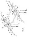
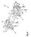
- a first embodiment of a fixation device 1 according to the inventioncan be seen.
- Thisis formed from two fixation elements 11 according to the invention, bone nails 7, to which the elements 11 are applied, and two fixation rods 6.
- Itis a fixator, which bridges a bone joint, such as a wrist outside with the two fixation rods 6, to establish a fixation connection between broken bone parts.
- the fixation elements 11are formed consistently.
- the fixation rods 6are in Fig. 1 and 2 shown in parallel orientation. However, the device according to the invention allows that they can also be adjusted with great deviation from the parallel alignment.
- the bone nails 7 for the fixation element 11are each in a line which runs at least almost parallel to the fixation rods 6.
- the Fixationslement 11has a cross-shaped base body 2, which is made in one piece and in one piece by a molded plastic injection molded part and to some extent for the production of clamping connections against material elastic restoring force issverformbar.
- a high-strength Plasticused relatively low specific gravity. Such a body can be produced with high precision in form and dimensional accuracy.
- the basic body 2which has a symmetrical cross shape, is formed by a circular-cylindrical longitudinal body part 201 and a transverse body part 202, which as a whole has an oval-shaped form and with its ends protrudes vertically from the cylindrical body part 201.
- the dimensions of each perpendicular to their long extension direction cross sections of the parts 201 and 202are of the same order of magnitude.
- a flat closed passage slot closed at the edgeis formed to form a receptacle 22 for a pair of bone nails 7.
- the slot receptacle 22extends with the transverse body part 202, wherein the slot with its flat surface is perpendicular to the central longitudinal axis 20 of the longitudinal body part 201 and open at free narrow sides of the cross body part 202 for placement on the bone nails 7.
- the longitudinal body part 201has an axial through-hole 23, through which a tensioning rod 501 of a tensioning connection 5 is passed.
- the fixation element 11is formed as a whole by a captive series arrangement of the base body 2, two rod clamp brackets 3 and clamping bracket bearing elements 41, 42 of a bearing 4 on the tension rod 501.
- the bar clamps 3enclose the body 2 between them, and this arrangement is frictionally edged with two ply-inlets 42 in the form of dome-shaped caps between their concave sides.
- the two bar clamp 3are designed to match.
- the clamping holder 3is formed by a one-piece, one-piece clamping ball 30 having an axial central passage opening 33 in the form of a bore.
- the passage opening 33merges at its opening ends in each case into a concave annular recess 34.
- Each ball 30, which is made of high-strength plastic,is positively received by the bearing 4.
- Each bearing 4has a respectively formed at the end of the longitudinal body part 201 bearing element 41 in the form of a .kalottenartigen, a concave bearing ring forming recess 413 and an associated bearing element 42.
- Each bearing element 42has a through hole 421, with which it is attached to the end of the tension rod 501 on this.
- the bearing element 42is at its the Bearing ball 30 facing side formed with a concave KreisringausEnglishung 423, which corresponds to the concave KreisringausEnglishung 413 of the bearing element 41.
- the clamp bearing ball 30is further formed with a slot receiving 31 for receiving and holding the fixation rod 6.
- the slot receptacle 31extends in a ball secant area in the ball equatorial plane without intersecting the axial through hole 33 of the ball 30.
- the slot receptacle 31is widened at its bottom corresponding to the circular cross-section of the fixation rod 6, so that a seat 311, which the fixation rod 6 passes through at its end, is formed.
- the walls of the slot 31form latching elements 312 which can be spread open against material elastic restoring force in order to allow the fixation rod 6 to snap into the seat 311 in a clamping manner.
- the receiving cross sections of the slot receptacle 31 and the material elasticity of the bearing ball 30are chosen so that the rod 6 is held automatically in the locked position by clamping, being axially and rotationally movable for positioning and adjustment against clamping friction force.
- the bearing ball 30is separated in its equatorial plane by a gap 301 in two halves, which are held together only on the slot receiving 31 opposite ball side in one piece by a wall web 302.
- the gap 301is formed by an incision.
- the one-piece bearing ball 30is particularly easy to handle. Instead, it is also possible to form the ball halves completely separated from each other.
- the passage opening 33passes through the gap 302.
- the tensioning rod 501 of the tensioning connection 5 of each fixation element 11is formed by shaft screws 51 and 52, which can be axially screwed together at their foot ends.
- the shaft screw 51is provided at its foot end with external thread and the shaft screw 52 at its foot end with internal thread.
- the Schique screws 51, 52have heads 53, each with an internal Mehrkantaus principleung for applying a screwdriver.
- Recessesare formed on the bearing elements 42 on the side facing away from the bearing ball 30, into which the screw heads 53 engage for mutual clamping of the parts lined up on the tension rod 501.
- each clamping holder 3The bearing ball 30 of each clamping holder 3 is mounted between the bearing rings 41, 42 so that it is guided in its seat in the bearing elements 41, 42 and three-dimensionally adjustable when the clamping connection 5 is sufficiently solved to a sufficiently large and limited spherical adjustment
- the axial passage opening 33is dimensioned sufficiently large, and the concave annular recesses 34 are conically widened from the opening 33 forth to the outside.
- the adjustment rangeis chosen to be so large that, starting from the in Fig. 1 illustrated position in which the two base body 2 are aligned parallel to the axes 20 of their longitudinal body parts 201 in a plane, the Lekss stressesmaschinemaschine 201 and their axes 20 at intersecting rods 6 against each other by at least 90 ° about one of the centers M1 and M2 of the cross pieces having imaginary bamboosachse 10 torsionally twisted or can be pivoted.
- the two axes 20can thus bring at least in a mutually perpendicular position.
- the imaginary axis 10is not fixed, but it can from the in Fig. 1 shown basic position to be moved in all spatial directions.
- the slot 22 of each base body 2 and the same bone nails 7 received by it in a pairare dimensioned so that the bone nails 7 are received in a clamping manner against elastic restoring force of the wall material of the base body 2 even when the tensioning connection 5 is completely loosened.
- At the slot 22is perpendicular to the axial in the middle of the body cross piece Through hole 23 directed recess 24 formed with one of the polygonal recess of the screw head 53 corresponding shape.
- the two bone nails 7each come to lie in the slot area, which extends into the projecting from the longitudinal body part 201 ends of the cross body part 202.
- the middle region of the receiving slot 22 between the nails 7 in the direction of the tensioning rod 501 during clampingis uniformly and distinctly elastically compressible.
- the shaping of the parts of the cross member body in combination with the plastic materials usedforms optimally effective cross sections for permanent and stable clamping of the tie rod connection. 5
- the surgical technique for applying the fixation device according to the inventionproves to be particularly simple and secure. After two pairs of bone nails 7 have been set in substantially one line in the usual way with a screwing tool and drill guide, the fixation element 11 is pushed onto each pair of nails. A rotary tool is inserted into the recess 24 and rotated to a position that the slot 31 is expanded to be pushed. In reset, he rotational position of the tool this is removed, and the fixation element is sitting to adjust by adjusting its position sufficiently strong, but slidable on the bone nails 7.
- the bearing balls 30are open with their SchlitzausEnglishept 31 on the side facing away from the bone files to be joined, and they can be conveniently adjusted three-dimensionally for insertion and adjustment of the rods 6 in fixable positions.
- the rods 6arrive first with their ends in captive click-latching positions in which they remain adjustable to adjust that they on the one hand by the automatic clamping action of the clamp-elastic ball 30 axially and rotationally and on the other hand by the spherical adjustment of the ball 30 in the camp 4 relocatable are.
- both the bone nails 7 and the fixation rods 6are adjustable by the automatic clamping action in the slot receiving 22 of the base body 2 and in the slot receiving 31 of the bearing ball 30 without influence of the clamping connection 5 for adjustment.
- the tension rod connection 5is tightened by tightening and tensioning the tension rod 501 to a defined torque. This is achieved according to the invention in that all clamps on the fixation element 11 are uniformly realized with only one tie rod connection 5.
- fixation device 1.2which consists of the same components as the fixation device 1.1 of Fig. 1 and 2 is joined fixation elements 12 of this arrangement are formed by the fact that are placed on the tension rod of the base body 2 and the rod clamp 3 only at one end of the cylindrical longitudinal body 201.
- the recess 413 of the bearing element 41serves to receive the screw head 53.
- a tension rod 501is used with screw members 51, 52 which allow a change in the span length in a wide range to both for the device Fig. 1 and 2 , as well as for the facility Fig. 3 to be used.
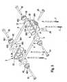
- Fig. 4 and 5show a fixation device 1.3 according to the invention in one embodiment with a modified fixation element 13th
- the fixation element 11is arranged as it is Fig. 1 and 2 has been described.
- the fixation rods 6are connected at their other ends to the modified fixation element 13.
- Thisis like the fixation element 11 executed with the exception that instead of the longitudinal body part 201, a longitudinal body part 203 is provided, which remains free of a cross member and instead with an additional oval-shaped longitudinal body part 204 is provided. This extends parallel to the body part 203, with which it is connected via an extension piece 131.
- a slot receptacle 25 for a pair of bone nails 7is formed in its extension direction.
- this slot with tool recess 24corresponds to the formation of the slot in the part 202 of the other fixation element 11.
- the fixation element 13serves to receive a pair of bone nails 7, which are transversely, in particular at least almost in a direction perpendicular to the rods 6 line.
- the body part 204has been formed separately and connected via a screw 26 with the integrally formed on the body 203 extension piece 131.
- the screw 26is also used to fix the bone nails 7 as in the slot receiving 22 in the slot receiving 25.
Landscapes
- Health & Medical Sciences (AREA)
- Orthopedic Medicine & Surgery (AREA)
- Life Sciences & Earth Sciences (AREA)
- Surgery (AREA)
- Biomedical Technology (AREA)
- Engineering & Computer Science (AREA)
- Nuclear Medicine, Radiotherapy & Molecular Imaging (AREA)
- Heart & Thoracic Surgery (AREA)
- Medical Informatics (AREA)
- Molecular Biology (AREA)
- Animal Behavior & Ethology (AREA)
- General Health & Medical Sciences (AREA)
- Public Health (AREA)
- Veterinary Medicine (AREA)
- Surgical Instruments (AREA)
Abstract
Description
Translated fromGermanDie Erfindung betrifft eine Fixationseinrichtung zum stabilen Verbinden wenigstens zweier Knochenteile eines gebrochenen Knochens, umfassend wenigstens einen Grundkörper zur festen Aufnahme jeweils wenigstens eines Knochennagels, wenigstens eine Fixationsstange, die mittels Klemmverbindung mit dem Grundkörper verbindbar ist, wobei Grundkörper und Fixationsstange in einem ersten Verbindungszustand der Fixationseinrichtung zum Einstellen ihrer relativen Position freigegeben sind und in einem zweiten Verbindungszustand zum Fixieren der eingestellten Position durch Kraftschluss steif miteinander verbunden sind, einen an dem Grundkörper winkelverstellbar gelagerten Klemmhalter, der eine Fixationsstange zum Verändern und Einstellen ihrer Position in einer Aufnahme aufnimmt, ein den Klemmhalter an dem Grundkörper lagerndes Lager und eine Verbindung mit einem Spannstab, an dem zum Gegeneinanderspannen der Grundkörper, der Stangen-Klemmhalter und das Lager für den Klemmhalter in Reihe angeordnet sind, wobei einerseits bei gelöster Spannstabverbindung die Freigabe-Verbindung und andererseits bei ausreichend großer Schließspannung in der Spannstab-verbindung die stabile Kraftschluss-Verbindung hergestellt sind, wobei der Stangen-Klemmhalter durch einen die Fixationsstange sphärisch verstellenden Halter gebildet ist, der in einem Bereich zum Verstellen und Beibehalten der eingestellten Position an dem Grundkörper in alle Raumrichtungen geführt ist, wobei sich der Klemmhalter und wenigstens ein von dem Spannstab durchfasstes Lagerelement des den Klemmhalter mit dem Grundkörper verbindenden Lagers im die räumliche Führung herstellenden Formschluss befinden. Die Erfindung bezieht sich auch auf ein Fixationselement einer solchen Einrichtung und einen ihre Bauteile aufnehmenden Bausatz in steriler Verpackung.The invention relates to a fixation device for stably connecting at least two bone parts of a fractured bone, comprising at least one base body for firmly receiving at least one bone nail, at least one fixation rod which is connectable by clamping connection with the base body, wherein the base body and fixation rod in a first connection state of the fixation device are set to adjust their relative position and are rigidly connected together in a second connection state for fixing the adjusted position by frictional connection, an angle adjustable mounted on the body clamp holder which receives a fixation rod for changing and setting their position in a receptacle, a the clamp holder bearing supporting the main body and a connection to a tensioning rod on which the base body, the rod-clamping holder and the bearing for the clamping holder in row a are arranged, on the one hand with released tie rod connection, the release connection and the other hand, at a sufficiently large clamping voltage in the tie rod connection, the stable adhesion connection are made, wherein the rod-clamping holder is formed by a fixation rod spherically adjusting holder, in one area for adjusting and maintaining the set position on the main body is guided in all spatial directions, wherein the clamping holder and at least one of the clamping rod durchfasstes bearing element of the clamping holder with the base body connecting bearing in the spatial guide producing positive engagement are. The invention also relates to a fixation element of such a device and a components receiving their components kit in sterile packaging.
Eine gattungsgemäße Einrichtung, die auch als Fixateur bezeichnet wird, dient dazu, eine Fixationsverbindung zwischen Knochenteilen herzustellen, um Frakturen zu behandeln. Insbesondere werden solche Fixateure bei Radiusfrakturen mit Gelenkbeteiligung angelegt. In die Knochenteile eingebrachte Knochennägel müssen steif mit wenigstens einer Fixationsstange verbunden werden, um das Zusammenwachsen der Knochenteile in richtiger Stellung zueinander zu ermöglichen. Nach Maßgabe der Anordnung und Ausrichtung der Knochennägel sowie der zu überbrückenden Strecke muss die Fixationsstange ausgerichtet werden können. In ausgerichteter Position muss sie steif mit den Grundkörpern verbindbar sein, die ihrerseits in stabiler steifer Verbindung an den Knochennägeln festzusetzen sind.A generic device, which is also referred to as a fixator, serves to establish a fixation connection between bone parts in order to treat fractures. In particular, such fixators are applied to radius fractures with joint involvement. In the bone parts introduced bone nails must be stiff with at least a fixation rod are connected to allow the growing together of the bone parts in the correct position to each other. According to the arrangement and orientation of the bone nails and the distance to be bridged, the fixation rod must be able to be aligned. In the aligned position, it must be rigidly connectable to the basic bodies, which in turn are to be fixed in a sturdy rigid connection to the bone nails.
An die Fixateure wird eine Reihe von Anforderungen gestellt. Es muss große Stabilität gewährleistet werden. Fixierte Knochen dürften während auch mehrwöchiger Tragezeit des Fixateurs ihre Position zueinander nicht verändern. Dies erfordert hohe Stabilität insbesondere in den Verbindungen einzelner Bauteile. Der Fixateur soll einfach handhabbar sein, um die Operationszeit zu verkürzen. Zudem soll er gewichtsmäßig relativ leicht bauen. Die Fixationseinrichtung soll auch kostengünstig zur Verfügung stehen. Dies hat insbesondere im Hinblick auf eine Einmalverwendung besondere Bedeutung, wenn sich diese gegenüber der Aufbereitung der Komponenten zur Wiederverwendung rentiert. So werden Fixateure, die in Folge hoher Anschaffungskosten mehrfach verwendet werden sollten, nach ihrer Anwendung häufig nicht zurückgegeben, so dass dadurch Verlust entsteht. Auch sind bei Wiederverwendung besondere Abläufe und Maßnahmen insbesondere zum Sterilisieren erforderlich.The fixators have a number of requirements. It must be ensured great stability. Fixed bones should not change their position during several weeks of fixation. This requires high stability, especially in the connections of individual components. The fixator should be easy to handle, to shorten the operation time. In addition, he should build relatively light in weight. The fixation device should also be available at low cost. This has particular significance with regard to a single use, if this is profitable compared to the preparation of the components for reuse. Thus fixators, which should be used several times as a result of high acquisition costs, are frequently not returned after their application, so that this results in loss. Also, reuse requires special procedures and measures, especially for sterilization.
Bekannte Fixateure werden den genannten Anforderungen nicht gerecht. Fixationselemente eines gattungsgemäßen Fixateurs umfassen einen Grundkörper mit einem Stangen-Klemmlager, das zum Positionieren einer Fixationsstange sphärisch verstellbar ist, wobei Teile des Fixationselements mittels eines Spannstabes verbunden sind (
Der Erfindung liegt das Ziel zugrunde, eine Fixationseinrichtung derart zu gestalten, dass sie besonders einfach handhabbar ist und mit relativ wenig Bauteilen kostengünstig zur Verfügung steht, wobei die Verbindungssteifigkeit besonders groß und zuverlässig über auch längeren Zeitraum gewährleistet sein soll. Dennoch soll es möglich werden, die Bauteile der Einrichtung aus Leichtwerkstoff und in kostengünstiger Massenproduktion, insbesondere aus im Spritzgussverfahren hergestellten Kunststoffteilen herzustellen. Die Herstellung soll gegebenenfalls so kostengünstig sein, dass das Produkt als billiges Einwegprodukt verwendbar ist, um insbesondere in einer Klinik die Abläufe zu vereinfachen, indem Rückführung, Wiederaufbereitung und Sterilisierung bereits verwendeter Fixateure vermieden werden.The invention is based on the object to design a fixation device such that it is particularly easy to handle and is relatively inexpensive available with relatively few components, the connection stiffness should be particularly large and reliable over longer period guaranteed. Nevertheless, it should be possible to produce the components of the device from lightweight material and in cost-effective mass production, in particular made of injection-molded plastic parts. The preparation should optionally be so inexpensive that the product can be used as a cheap disposable product to simplify the processes, especially in a clinic by repatriation, reprocessing and sterilization of already used fixators are avoided.
Die Ziele der Erfindung werden in Verbindung mit den Merkmalen der Fixationseinrichtung der eingangs genannten Art dadurch erreicht, dass der Klemmhalter auf dem Spannstab aufgereiht ist, wobei er eine Durchgangsöffnung aufweist, die derart ausgebildet ist, dass der Spannstab mit für die räumliche Führung des Klemmhalters ausreichendem Bewegungsspielraum in der Durchgangsöffnung durch diese hindurchgesetzt ist. Mit der erfindungsgemäßen Lösung wird eine Reihe von Vorteilen erzielt. Durch die dreidimensionale Bewegungsführung und Verstellbarkeit des Klemmhalters wird die Einstellung und die Verbindung des Fixationselements mit Fixationsstangen besonders vereinfacht und erleichtert. Zudem trägt dies in besonderem Maße dazu bei, dass Stange und Grundkörper bzw. Klemmlager im Zustand der Kraftschlussverbindung nicht mit Kräften quer zu dem Spannstab verspannt werden. Dies erhöht die Festigkeit und Stabilität der Einrichtung in besonderem Maß. Hinsichtlich einfacher Bauform ist es besonders vorteilhaft, dass der Klemmhalter für die Klemmstange ein Lager bildet, das als solches in Gänze dreidimensional, also in alle Raumrichtungen bewegbar ist. Die Spannstabverbindung baut besonders einfach, da zu klemmende Teile einschließlich des an dem Grundkörper in alle Raumrichtungen geführten und verstellbaren Klemmhalters durch ein und denselben Zugstab der Spannverbindung gelöst und in steifer Verbindung aneinander befestigt werden. Spannkraft wird einheitlich für unterschiedliche Teile des Spannverbundes aufgebracht, nämlich sowohl für das Festsetzten der Fixationsstange in ihrem Klemmhalter, als auch zum Festsetzen des räumlich winkelverstellbaren Klemmhalters in einem Lagerelement an dem Grundkörper. Die erfindungsgemäße Verbindungs- und Bauform erlaubt es, die Bauteile relativ einfach auszuführen. Die Herstellungskosten der Einzelteile bleiben niedrig. Gegenüber herkömmlichen Einrichtungen wird der Aufwand für Einzelteile hinsichtlich Zahl, Handhabung und Nutzung erheblich reduziert. Insbesondere können durch verspanende Formgebung herzustellende Teile vermieden und statt dessen Leichtbauteile vorzugsweise aus Kunststoff-Spritzgussteilen eingesetzt werden.The objectives of the invention are achieved in conjunction with the features of the fixation device of the type mentioned above in that the clamping holder is lined up on the tension rod, wherein it has a passage opening which is designed such that the tension rod sufficient for the spatial guidance of the clamping holder Movement in the passage opening is passed through this. With the solution according to the invention, a number of advantages are achieved. The three-dimensional motion control and adjustability of the clamping holder, the setting and the connection of the fixation element with fixation rods is particularly simplified and easier. In addition, this contributes particularly to the fact that rod and body or clamping bearing in the state of frictional connection are not clamped with forces transverse to the tension rod. This increases the strength and stability of the device in particular. With regard to a simple design, it is particularly advantageous that the clamping holder forms a bearing for the clamping rod, which as such is entirely three-dimensional, ie movable in all spatial directions. The tie rod connection is particularly simple, since to be clamped parts including the run on the body in all spatial directions and adjustable clamping bracket solved by one and the same pull rod of the clamping connection and secured together in a rigid connection. Clamping force is applied uniformly for different parts of the clamping assembly, namely both for fixing the fixation rod in its clamp holder, as well as for setting the spatially adjustable clamping bracket in a bearing element on the body. The connection and construction according to the invention makes it possible to carry out the components relatively easily. The manufacturing costs of the items remain low. Compared to conventional equipment is the cost of individual parts Considerably reduced in terms of number, handling and use. In particular, parts produced by means of a swirling shaping can be avoided and, instead, lightweight components can preferably be used made of plastic injection-molded parts.
Ein besonders universell verwendbares erfindungsgemäßes Fixationselement erreicht man dadurch, dass auf dem Spannstab wenigstens ein Grundkörper und am Grundkörper gegenüberliegend zwei Stangen-Klemmhalter mit ihren Lagerteilen in Reihe aufgesetzt sind. Zweckmäßig wird bei dieser Gestaltung der Grundkörper durch ein kreuzförmiges Element gebildet, umfassend einen zylindrischen Längskörperteil, der an seinen Enden Lagerflächen jeweils für einen Klemmhalter aufweist, und einen Querkörperteil, der wenigstens einen Knochennagel aufnimmt. Diese Formgebung des Grundkörpers, dessen Längskörperteil von dem Spannstab durchgriffen wird, weist für Druck- und/ oder Biegebelastung relativ große Widerstands-Querschnitte auf, so dass die Spannverbindung besonders fest und stabil ist. Zweckmäßig ist längs der Erstreckung des Querkörperteils in diesem ein Durchgangsschlitz ausgebildet, der Knochennägel in von dem Längskörperteil abstehenden Bereichen des Querkörperteils aufnimmt. Dies führt sowohl zu einer räumlich besonders günstigen Anordnung der Knochennägel, als auch zu einer besonders wirksamen und ausgeprägten Spannkraftübertragung längs des Längskörperteils. Damit erreicht man auch, dass ein Anziehen zum Spannen der Verbindung mit nur relativ geringem Anziehdrehmoment verbunden ist.A particularly universally usable fixation element according to the invention is achieved in that on the tension rod at least one base body and the base body opposite two bar clamps are placed with their bearing parts in series. Appropriately, in this design, the base body is formed by a cross-shaped element, comprising a cylindrical longitudinal body part, which has at its ends bearing surfaces each for a clamp holder, and a transverse body part, which receives at least one bone nail. This shaping of the base body, whose longitudinal body part is penetrated by the tension rod, has pressure and / or bending load on relatively large resistance cross-sections, so that the clamping connection is particularly strong and stable. Expediently, a passage slot is formed along the extension of the transverse body part, which accommodates bone nails in regions of the transverse body part projecting from the longitudinal body part. This leads both to a spatially particularly favorable arrangement of the bone nails, as well as to a particularly effective and pronounced clamping force transmission along the Längskörperteils. This also achieves that tightening to tighten the connection is associated with only a relatively low tightening torque.
Aufgrund der erfindungsgemäßen Maßnahmen lässt sich ein Fixationselement, umfassend den Grundkörper und wenigstens einen mittels der Spannstabverbindung daran gehaltenen Stangen-/Klemmhalter, als kompaktes, in einfachem Verbund zusammengefügtes Teil für sich besonders einfach handhaben und auf zweckmäßig zwei Knochennägel aufsetzen.Due to the inventive measures can be a fixation element, comprising the body and at least one means of the tie rod connection held rod / clamp holder, as a compact, assembled in a simple composite part for itself particularly easy to handle and put on two bone bones appropriately.
Vorteilhaft wird die Spannstab-Verbindung durch eine Schrauben-Schaftverbindung gebildet. Diese weist zweckmäßig zwei Schrauben mit Längschaft auf, die in einem Durchgang des Grundkörpers aneinander geschraubt werden, so dass schon durch wenige Umdrehungen der beiden Schrauben relativ zueinander ein durch Verkürzung wirksamer Spannstab gebildet ist. Die damit verklemmten Teile werden in gerader Linie gleichmäßig auf Klemmdruck beansprucht. Statt dessen kann zum Beispiel auch ein durchgehender Spannstab Verwendung finden, der an wenigstens einem Ende in Schraubverbindung mit einer anziehbaren Mutter abschließt.Advantageously, the tension rod connection is formed by a screw-shaft connection. This expediently has two screws with longitudinal shank, which are screwed together in a passage of the base body, so that even by a few turns of the two screws relative to each other by shortening effective tension rod is formed. The jammed parts are stressed in a straight line evenly to clamping pressure. Instead, for example, a continuous tension rod find use, which terminates at least one end in threaded connection with an attractable nut.
Eine besondere Gestaltung der Erfindung besteht darin, dass die Spannstabverbindung zusätzlich zu ihrer Funktion zum Festsetzen des Stangenhalters und der Stange ein Spannmittel bildet, das in dem Freigabe-Verbindungszustand wenigstens einen Knochennagel bewegbar in einen Grundkörper eingreifen lässt, der einteilig vorzugsweise aus Leichtwerkstoff wie Kunststoff gefertigt ist, während es den Knochennagel in dem Kraftschluss-Verbindungszustand kraftschlüssig stabil an dem Grundkörper festsetzt.A particular embodiment of the invention is that the tension rod connection in addition to its function for locking the rod holder and the rod forms a clamping means which can engage in the release connection state at least one bone nail movable in a body, the one piece preferably made of lightweight material such as plastic is while stably locking the bone nail in the frictional connection state frictionally to the body.
Vorteilhaft ist in dem Grundkörper wenigstens ein Schlitz zum verstellbaren Aufnehmen und zum Befestigen eines Knochennagels durch Klemmung ausgebildet, wobei der Grundkörper beim Spannen der Spannstabverbindung im Bereich des Schlitzes elastisch verformt wird. Zweckmäßig werden der Schlitz des Grundkörpers und wenigstens ein von ihm aufgenommener Knochennagel so dimensioniert, dass der Knochennagel im Freigabezustand der Spannstabverbindung zum Einstellen der Verbindungsposition zwischen Knochennagel und Grundkörper im Klemmschiebesitz von dem Schlitz aufgenommen wird. In dieser Ausführung lässt sich der Grundkörper besonders einfach und sicher auf Knochennägeln anbringen.Advantageously, in the base body at least one slot for adjustably receiving and fixing a bone nail is formed by clamping, wherein the base body is elastically deformed during clamping of the tension rod connection in the region of the slot. Appropriately, the slot of the body and at least one of his recorded bone nail are dimensioned so that the bone nail is received in the release state of the tie rod connection for adjusting the connection position between bone nail and body in the clamping sliding seat of the slot. In this version, the base body can be attached to bone nails in a particularly simple and secure manner.
Erfindungsgemäß kann der Stangen-Klemmhalter vorteilhaft als selbständiges Klemmelement ausgebildet werden, das im Freigabezustand der Spannstabverbindung wenigstens eine Fixationsstange im Klemmsitz aufnimmt. Besonders vorteilhaft kann der Klemmhalter als selbsttätig wirkendes Klemmelement ausgebildet werden, das die Fixationsstange im materialelastischem Klemmsitz aufnimmt. Die Fixationsstange lässt sich wenigstens in axialer Richtung gegen Haftreibung zum Positionieren bewegen. Auch kann der Stangen-Klemmhalter zweckmäßig so ausgebildet werden, dass die Aufnahme für die Fixationsstange eine Öffnung aufweist, durch die die Stange im Freigabezustand der Spannstabverbindung in einen durch wenigstens ein verdrängbares Rastelement hergestellten Sitz gelangt. Dies erleichtert die Handhabung wesentlich, da der Fixationsstab aufgrund dieser Maßnahme durch eine Klick-Verbindung in eine Position zum Einstellen gesetzt wird. Ein Entweichen der Stange in Einsetzrichtung wird dadurch verhindert. Dennoch bleibt sie in wenigstens einer Dimension zum Einstellen bewegbar.According to the invention, the rod-clamping holder can be advantageously formed as an independent clamping element, which receives at least one fixation rod in the clamping state in the release state of the tension rod connection. Particularly advantageously, the clamping holder can be formed as a self-acting clamping element which receives the fixation rod in the material-elastic clamping fit. The fixation rod can be moved at least in the axial direction against static friction for positioning. Also, the rod clamp can be suitably formed so that the receptacle for the fixation rod has an opening through which the rod passes in the release state of the tension rod connection in a seat produced by at least one displaceable latching element. This facilitates the handling substantially, since the fixation rod is set by virtue of this measure by a click connection in a position for setting. An escape of the rod in the insertion direction is thereby prevented. Nevertheless, it remains movable in at least one dimension to adjust.
In weiterer besonders bevorzugter Gestaltung der Erfindung weist der dreidimensional bewegbare Stangen-Klemmhalter wenigstens zwei Durchgangsöffnungen auf, wobei eine erste Öffnung durch eine zentrale Durchgangs-Axialöffnung gebildet wird, durch die der Spannstab der Spannstabverbindung unter ausreichendem Belassen von radialem Spiel für die dreidimensionale Bewegung hindwchgesetzt ist, und wobei wenigstens eine zweite Öffnung quer zur Axialöffnung und ohne diese zu schneiden durch den Halter hindurchgeht und die Klemmaufnahme für die Fixationsstange bildet.In a further particularly preferred embodiment of the invention, the three-dimensionally movable rod-clamp holder has at least two passage openings, wherein a first opening is formed by a central passage axial opening through which the tension rod of the tie rod connection is Hindwchgesetzt leaving sufficient radial play for the three-dimensional movement , and wherein at least a second opening transversely to the axial opening and without cutting through the holder passes through and forms the clamping receptacle for the fixation rod.
Zweckmäßig weist der an dem Grundkörper dreidimensional geführte Halter Kugelflächenabschitte auf, mit denen er im Formschluss zwischen auf dem Spannstab der Spannstabverbindung aufgereihten ringförmigen Lagerelementen gelagert ist, wobei das eine Lagerelement an dem auf dem Spannstab gehaltenen Grundkörper angeordnet ist. Eine besonders vorteilhafte Maßnahme besteht darin, dass die zentrale Durchgangsöffnung des Klemmhalters im Bereich wenigstens einer Lager-Kugelfläche aufgeweitet wird, um einen dadurch begrenzten sphärischen Halter-Verstellbereich vorzusehen. Um die Bauteilzahl besonders gering zu halten, wird der Klemmhalter zweckmäßig durch eine einteilige Kugel gebildet. Vorteilhaft wird ein ein solcher Halter mit einer Stangen-Klemmaufnahme ausgebildet, die an der Halteroberfläche einen offenen Schlitz zur Aufnahme der Fixationsstange bildet.Suitably, the three-dimensionally guided on the body holder Kugelflächenabschitte with which it is mounted in the form-fitting between lined up on the tie rod of the tie rod connection annular bearing elements, wherein the one bearing element is arranged on the base body held on the tension rod. A particularly advantageous measure is that the central passage opening of the clamping holder is widened in the region of at least one bearing spherical surface in order to provide a spherical holder adjustment area bounded thereby. In order to keep the number of components particularly low, the clamp is expediently formed by a one-piece ball. Advantageously, such a holder is formed with a rod-clamping receptacle which forms an open slot for receiving the fixation rod on the holder surface.
Um die Kraftschlussverbindung besonders zu verstärken, besteht eine erfindungsgemäße Maßnahme darin, dass wenigstens ein Teil der Klemmflächen der Fixationseinrichtung strukturiert ist. Zweckmäßig weist die Strukturierung eine Aufrauung, Rillen, Noppen und/oder ein entsprechendes Mittel zum Herstellen eines besonders innigen Eingriffs aufIn order to reinforce the frictional connection particularly, a measure according to the invention is that at least a part of the clamping surfaces of the fixation device is structured. The structuring expediently has a roughening, grooves, nubs and / or a corresponding means for producing a particularly intimate engagement
Durch die erfindungsgemäßen Maßnahmen erreicht man eine relativ geringe Zahl von Bauteilen, die sich insbesondere als kostengünstige Leichtbauteile in Form eines kompakten Bausatzes in steriler Verpackung bereithalten lassen.The inventive measures to achieve a relatively small number of components, which can be prepared in particular as cost-effective lightweight components in the form of a compact kit in sterile packaging.
Weitere bevorzugte Merkmale, Ausführungsformen und Möglichkeiten der Erfindung gehen aus Unteransprüchen und der Beschreibung hervor. Besonders bevorzugte Ausführungsbeispiele werden anhand der Zeichnung näher erläutert. In der Zeichnung zeigen
- Fig. 1 und 2
- in axonometrischer Darstellung und in Explosionsdarstellung eine erfindungsgemäße Fixationseinrichtung mit zwei durch zwei Fixationsstangen verbundenen Fixationselementen,
- Fig. 3
- in axonometrischer Darstellung eine erfindungsgemäße Fixations- einrichtung mit zwei durch nur eine Fixationsstange verbundenen Fixationselementen und
- Fig. 4 und 5
- eine axonometrischer Darstellung sowie in Explosionsdarstellung eine erfindungsgemäße Fixationseinrichtung mit zwei Verbin- dungsstangen und zwei Fixationselementen, die Knochennägel in unterschiedlicher Anordnung aufnehmen.
- Fig. 1 and 2
- in axonometric view and in exploded view, a fixation device according to the invention with two fixation elements connected by two fixation rods,
- Fig. 3
- in axonometric view, a fixation device according to the invention with two fixation elements connected by only one fixation rod, and
- 4 and 5
- an axonometric view and an exploded view of a fixation device according to the invention with two connecting rods and two fixation elements that record bone nails in a different arrangement.
Aus
Das Fixationslement 11 weist einen kreuzförmigen Grundkörper 2 auf, der einteilig und einstückig durch ein im Spritzgussverfahren geformtes Kunststoffteil hergestellt wird und in gewissem Maß zum Herstellen von Klemmverbindungen gegen materialelastische Rückstellkraft eigenverformbar ist. Zur Spritzgussfertigung wird ein hochfester Kunststoff relativ geringen spezifischen Gewichts verwendet. Ein solcher Körper lässt sich mit hoher Präzision in Form- und Maßhaltigkeit herstellen.The
Der eine symmetrische Kreuzform aufweisende Grundkörper 2 ist durch einen kreiszylindrischen Längskörperteil 201 und einen Querkörperteil 202 gebildet, der im Ganzen ovalförmige Form aufweist und mit seinen Enden von dem Zylinderkörperteil 201 senkrecht absteht. Die Dimensionen der jeweils zu ihrer langen Erstreckungsrichtung senkrechten Querschnitte der Teile 201 und 202 liegen in der gleichen Größenordnung. In den Querkörperteil 202 ist ein randseitig geschlossener, flacher Durchgangsschlitz zum Bilden einer Aufnahme 22 für ein Paar Knochennägel 7 ausgebildet. Die Schlitzaufnahme 22 erstreckt sich mit dem Querkörperteil 202, wobei der Schlitz mit seiner flachen Fläche senkrecht zur zentralen Längsachse 20 des Längskörperteils 201 steht und an freien Schmalseiten des Querkörperteils 202 zum Aufsetzen auf die Knochennägel 7 offen ist. Der Längskörperteil 201 weist eine axiale Durchgangsbohrung 23 auf, durch die ein Spannstab 501 einer Spannverbindung 5 hindurchgesetzt ist.The
Das Fixationselement 11 wird im Ganzen durch eine unverlierbare Reihenanordnung des Grundkörpers 2, von zwei Stangen-Klemmhaltern 3 und von Klemmhalter-Lagerelementen 41, 42 eines Lagers 4 auf dem Spannstab 501 gebildet. Die Stangen-Klemmhalter 3 schließen den Grundkörper 2 zwischen sich ein, und diese Anordnung wird mit zwei Lagen-ingelementen 42 in Form von kalottenartigen Kappen zwischen deren konkaven Ringseiten formschlüssig eingefasst.The
Die beiden Stangen-Klemmhalter 3 sind übereinstimmend ausgebildet. Der Klemmhalter 3 wird durch eine einteilige, einstückige Klemmkugel 30 gebildet, die eine axiale zentrale Durchgangsöffnung 33 in Form einer Bohrung aufweist. Die Durchgangsöffnung 33 geht an ihren Öffnungsenden jeweils in eine konkave Ringausnehmung 34 über. Jede Kugel 30, die aus hochfestem Kunststoff gefertigt wird, wird formschlüssig von dem Lager 4 aufgenommen. Jedes Lager 4 weist ein jeweils am Ende des Längskörperteils 201 ausgeformtes Lagerelement 41 in Form einer.kalottenartigen, einen konkaven Lagerring bildenden Ausnehmung 413 und ein zugehöriges Lagerelement 42 auf. Jedes Lagerelement 42 weist ein Durchgangsloch 421 auf, mit dem es am Ende des Spannstabes 501 auf diesen aufgesteckt ist. Das Lagerelement 42 ist an seiner der Lagerkugel 30 zugewandten Seite mit einer konkaven Kreisringausnehmung 423 ausgebildet, die der konkaven Kreisringausnehmung 413 des Lagerelements 41 entspricht.The two
Die Klemmhalter-Lagerkugel 30 ist weiterhin mit einer Schlitzaufnahme 31 zum Aufnehmen und Halten der Fixationsstange 6 ausgebildet. Die Schlitzaufnahme 31 erstreckt sich in einem Kugel-Sekantenbereich in der Kugel-Äquatorialebene, ohne dass sie die axiale Durchgangsöffnung 33 der Kugel 30 schneidet. Die Schlitzaufnahme 31 ist an ihrem Boden entsprechend dem Kreisquerschnitt der Fixationsstange 6 aufgeweitet, so dass ein Sitz 311, den die Fixationsstange 6 an ihrem Ende durchfasst, gebildet ist. Im Übrigen bilden die Wände des Schlitzes 31 Rastelemente 312, die gegen materialelastische Rückstellkraft aufspreizbar sind, um die Fixationsstange 6 klemmend in den Sitz 311 einrasten zu lassen. Die Aufnahmequerschnitte der Schlitzaufnahme 31 und die Materialelastizität der Lagerkugel 30 werden so gewählt, dass die Stange 6 in eingerasteter Position durch Klemmung selbsttätig gehalten wird, wobei sie zum Positionieren und Justieren gegen Klemm-Reibkraft axial und rotatorisch bewegbar ist. Zudem ist die Lagerkugel 30 in ihrer Äquatorialebene durch einen Spalt 301 in zwei Hälften getrennt, die nur an der der Schlitzaufnahme 31 gegenüberliegenden Kugelseite einstückig durch einen Wandsteg 302 zusammengehalten werden. Der Spalt 301 wird durch einen Einschnitt gebildet. Die einteilige Lagerkugel 30 lässt sich besonders einfach handhaben. Statt dessen ist es auch möglich, die Kugelhälften vollständig getrennt voneinander auszubilden.The
Die Durchgangsöffnung 33 geht durch den Spalt 302 hindurch. Dadurch erreicht man, dass die Kugelhälften mit gleichmäßiger und relativ geringer Spannkraft der Spannstabverbindung 5 zum Festsetzen der Stange 6 in der Schlitzaufnahme 31 gegeneinander gespannt werden. Die dabei über die Lagerelemente 41, 42 ausgeübte Spannkraft klemmt zudem die Lagerkugel 30 zwischen den Lagerelementen 41, 42 ein, so dass zugleich auch die Kugel 30 in ihrer Position einfach und sohr stabil fixiert wird. Der Durchmesser der Lagerkugel 30 ist nur geringfügig größer als der Querschnittsdurchmesser des zylindrischen Längskörperteils 203 und des Lagerelements 42. Infolgedessen bilden die Lagerkugeln 30 hochwirksame Klemmelemente in der auf dem Spannstab 501 aufgereihten Anordnung, wenn diese durch den Spannstab 501 aneinander gezogen werden.The
Der Spannstab 501 der Spannverbindung 5 eines jeden Fixationselements 11 wird durch an ihren Fußenden axial aneinander schraubbare Schaftschrauben 51 und 52 gebildet. Zu diesem Zweck ist die Schaftschraube 51 an ihrem Fußende mit Außengewinde und die Schaftschraube 52 an ihrem Fußende mit Innengewinde versehen. Die Schaßschrauben 51, 52 weisen Köpfe 53 mit jeweils einer Innen-Mehrkantausnehmung zum Ansetzen eines Schraubendrehers auf. An den Lagerelementen 42 sind jeweils auf der der Lagerkugel 30 abgewandten Seite Ausnehmungen ausgeformt, in die die Schraubenköpfe 53 zum Gegeneinanderspannen der auf dem Spannstab 501 aufgereihten Teile eingreifen.The
Die Lagerkugel 30 eines jeden Klemmhalters 3 wird so zwischen den Lagerringen 41, 42 formschlüssig gelagert, dass sie in ihrem Sitz in den Lagerelementen 41, 42 geführt und dreidimensional verstellbar ist, wenn die Spannverbindung 5 ausreichend gelöst ist Um einen ausreichend großen und begrenzten sphärischen Verstellbereich zu erhalten, ist die axiale Durchgangsöffnung 33 ausreichend groß bemessen, und die konkaven Ringausnehmungen 34 sind kegelartig von der Öffnung 33 her nach außen aufgeweitet.The bearing
Vorteilhaft und zweckmäßig wird der Verstellbereich so groß gewählt, dass, ausgehend von der in
Der Schlitz 22 eines jeden Grundkörpers 2 und die von ihm im Paar aufgenommenen gleichen Knochennägel 7 sind so dimensioniert, dass die Knochennägel 7 auch bei vollständig gelöster Spannverbindung 5 im Schiebesitz gegen elastische Rückstellkraft des Wandmaterials des Grundkörpers 2 klemmend aufgenommen werden. An dem Schlitz 22 ist in der Mitte des Grundkörper-Kreuzstückes eine senkrecht zur axialen Durchgangsbohrung 23 gerichtete Ausnehmung 24 mit einer der Mehrkantausnehmung des Schraubenkopfes 53 entsprechenden Ausformung ausgebildet. Durch Einsetzen und Drehen des Drehwerkzeugs, mit dem auch die Spannverbindung 5 gespannt wird, lässt sich der Schlitz 22 gegen materialelastische Rückstellkraft der Schlitzwandung etwas aufweiten, um das Fixationselement 11 bequem auf das Knochennägel-Paar aufzusetzen. Dabei kommen die beiden Knochennägel 7 jeweils in dem Schlitzbereich zu liegen, der sich in den von dem Längskörperteil 201 abstehenden Enden des Querkörperteils 202 erstreckt. Die Anordnung der Knochennägel 7 in den Enden des Querkörperteils 202, die von dem Längskörperteil 201 abstehen, führt zu besonders wirksamen Klemmungen in dem erfindungsgemäßen Spannverbund. So erreicht man, dass der mittlere Bereich des Aufnahmeschlitzes 22 zwischen den Nägeln 7 in Richtung des Spannstabes 501 beim Spannen gleichmäßig und ausgeprägt elastisch druckverformbar ist. Auch die Ausformung der Teile des Grundkörper-Kreuzstückes in Paarung mit den verwendeten Kunststoffmaterialien bildet optimal wirksame Querschnitte zum dauerhaften und stabilen Spannen der Spannstabverbindung 5.The
Die Operationstechnik zum Anlegen der erfindungsgemäßen Fixationeinrichtung erweist sich als besonders einfach und sicher. Nachdem zwei Paar Knochennägel 7 in im Wesentlichen einer Linie in üblicher Weise mit Eindrehwerkzeug und Bohrlehre gesetzt worden sind, wird auf jedes Nägelpaar jeweils das Fixationselement 11 aufgeschoben. Ein Drehwerkzeug wird in die Ausnehmung 24 gesteckt und in eine Position gedreht, dass der Schlitz 31 zum Aufschieben aufgeweitet wird. In zurückgestellt,er Drehposition des Werkzeugs wird dieses entnommen, und das Fixationselement sitzt zum Justieren durch Verstellen seiner Position ausreichend fest, aber verschiebbar auf den Knochennägeln 7. Nachdem beide Fixationselemente 11 an die zugehörigen Knochennägel 7 angelegt worden sind, werden die beiden Fixationsstangen 6 eingesetzt. Die Lagerkugeln 30 sind mit ihren Schlitzausnehmungen 31 an der Seite offen, die den zu verbindenden Knochenfeilen abgewandt ist, und sie lassen sich zum Einsetzen und Verstellen der Stangen 6 in festsetzbare Positionen bequem dreidimensional räumlich verstellen. Dabei gelangen die Stangen 6 zunächst mit ihren Enden in unverlierbare Klick-Rastpostionen, in denen sie zum Justieren dadurch verstellbar bleiben, dass sie einerseits durch die selbsttätige Klemmwirkung der klemmelastischen Kugel 30 axial und rotatorisch und andererseits durch die sphärische Verstellung der Kugel 30 in dem Lager 4 verlagerbar sind. Mit der erfindungsgemäßen in einer Einheit zusammengefassten universellen Verstellmöglichkeit zum Justieren wird erreicht, dass die beiden Fixationsstangen 6 zueinander weitgehend spannungsfrei gehalten werden. Dabei ist es sehr vorteilhaft, dass sowohl die Knochennägel 7 als auch die Fixationsstangen 6 durch die selbsttätige Klemmwirkung in der Schlitzaufnahme 22 des Grundkörpers 2 und in der Schlitzaufnahme 31 der Lagerkugel 30 ohne Einfluss der Spannverbindung 5 zum Justieren verstellbar sind. Zudem ist es aber auch möglich, die Spannstabverbindungen 5 geringfügig anzuziehen, um den Eigenklemmungen eine zusätzliche Komponente zum Justieren zu überlagern. Zum vollständigen Festsetzen der Teile aneinander wird die Spannstabverbindung 5 durch Festziehen und Spannen des Spannstabes 501 bis zu einem definierten Drehmoment gespannt. Dies gelingt erfindungsgemäß dadurch, dass sämtliche Klemmungen am Fixationselement 11 mit nur der einen Spannstabverbindung 5 einheitlich verwirklicht werden.The surgical technique for applying the fixation device according to the invention proves to be particularly simple and secure. After two pairs of
Aus
An einem Ende der Anordnung der im Wesentlichen sich parallel erstreckenden Fixationsstangen 6 ist das Fixationselement 11 angeordnet, wie es zu
Im Ausführungsbeispiel der
Claims (25)
- Fixation device (1) for the stable connection of at least two bone portions of a broken bone, including at least one base body (2) for tightly receiving at least one bone nail (7), at least one fixation rod (6) which can be connected to the base body (2) by means of a clamping joint, wherein base body (2) and fixation rod (6) are released in a first connection state of the fixation device (1) for adjusting their relative position and rigidly connected to each other by non-positive locking in a second connection state for fixing the adjusted position, a clamping holder (3) which is mounted with adjustable angle on the base body (2) and which receives the fixation rod (6) for altering and adjusting its position in a receptacle (31), a bearing (4) which mounts the clamping holder (3) on the base body (2), and a connection (5) to a tensioning rod (501) on which the base body (2), the rod clamping holder (3) and the bearing (4) for the clamping holder (3) are arranged in a row for tensioning relative to each other, wherein on the one hand the released connection is made when the tensioning rod connection (5) is released, and on the other hand the stable non-positive locking connection is made when there is sufficient closing tension in the tensioning rod connection (5), wherein the rod clamping holder (3) is formed by a holder which spherically displaces the fixation rod (6) and which is guided in all spatial directions in a region for displacing and maintaining the set position on the base body (2), the clamping holder (3) and at least one bearing element (41, 42) of the bearing (4) connecting the clamping holder (3) to the base body (2) being in a positive engagement which produces the spatial guiding, the tensioning rod (501) passing through the bearing element (41, 42),characterised in that the clamping holder (3) is lined up on the tensioning rod (501), comprising a through-opening (33) which is designed in such a way that the tensioning rod (501) passes through the through-opening (33) with sufficient play in the through-opening (33) for spatial guidance of the clamping holder (3).
- Fixation device according to claim 1,characterised in that the base body (2) is formed in one piece, preferably from a lightweight material, in particular plastic, andin that at least one such base body (2), a rod clamping holder (3) and a clamping holder bearing element (41, 42) each are placed in a row on a tensioning rod (501) of the tensioning connection (5).
- Fixation device according to claim 1 or 2,characterised in that on the tensioning rod (501) are placed in a row at least one base body (2) and on the base body (2) opposite each other two rod clamping holders (3) with their bearing portions (41, 42).
- Fixation device according to any one of claims 1 to 3,characterised in that the tensioning rod connection (5) is formed by a screw/shank connection.
- Fixation device according to any one of claims 1 to 4,characterised in that the rod clamping holder (3) comprises at least two through-openings (31, 33), wherein a first opening (33) is formed by a central axial through-opening through which the tensioning rod (501) of the tensioning rod connection (5) is passed, leaving sufficient radial play for the three-dimensional movement, and wherein at least one second opening passes through the holder (3) transversely to the axial opening (33) and without intersecting the latter and forms the clamping receptacle (31) for the fixation rod (6).
- Fixation device according to claim 5,characterised in that the clamping holder (3) comprises spherical surface sections with which it is mounted in positive engagement between annular bearing elements (41, 42) in a row on the tensioning rod (501) of the tensioning rod connection (5), wherein one bearing element (41) is arranged on the base body (2) which is held on the tensioning rod (501), preferably formed integrally with the base body (2).
- Fixation device according to claim 6,characterised in that the central through-opening (33) of the holder (3) is expanded in the region of at least one spherical surface of the bearing in order to provide a spherical holder displacement region which is limited thereby.
- Fixation device according to claim 6 or 7,characterised in that the holder (3) is formed by a one-part or two-part ball (30).
- Fixation device according to any one of claims 6 to 8,characterised in that the spherical-surface holder (3) is in one piece and designed with a clamping receptacle (31) for the fixation rod (6), the clamping receptacle (31) being appropriately designed as an open receiving slot on the holder surface.
- Fixation device according to any one of claims 1 to 9,characterised in that the tensioning rod connection (5) in addition forms a tensioning means which in the released connection state lets at least one bone nail (7) movably engage in a base body (2) which is manufactured in one piece preferably from lightweight material such as plastic, while it fixes the bone nail (7) to the base body (2) in a non-positive locking stable relationship in the non-positive locking connection state.
- Fixation device according to claim 10,characterised in that in the base body (2) is formed at least one slot (22) for adjustably receiving and fastening at least one bone nail (7) by clamping, the base body (2) being elastically deformed in the region of the slot (22) upon tensioning the tensioning rod connection (5).
- Fixation device according to claim 11,characterised in that the slot (22) in the base body (2) and at least one bone nail (7) received by it are dimensioned such that in the released state of the tensioning rod connection (5) the bone nail (7) is received by the slot (22) in a clamping/sliding fit for adjusting the connecting position between bone nail (7) and base body (2).
- Fixation device according to claim 12,characterised in that the slot (22) has a wall of elastic material such that the slot cross-section can be expanded for introducing the bone nail (7) against return force by means of a tool.
- Fixation device according to claim 13,characterised in that on the slot (22) in the base body (2) is formed a recess (24) for applying the tool for elastic expansion of the slot.
- Fixation device according to claim 13 or 14,characterised in that the tensioning rod connection (5) is provided with a means (53) for tensioning and relaxing, which can be actuated with the tool for expansion of the slot (22) in the base body.
- Fixation device according to any one of claims 1 to 15,characterised in that, in the released state of the tensioning rod connection (5), the rod clamping holder (3) receives at least one fixation rod (6) in a press fit which holds independently and appropriately clamps due to the elasticity of the material, wherein the fixation rod (6) in this fit is movable at least in the axial direction for positioning.
- Fixation device according to any one of claims 1 to 16,characterised in that on the receptacle (31) of the rod clamping holder (3) is formed an opening through which the fixation rod (6) passes in the released state of the tensioning rod connection (5) into a fit produced by at least one displaceable latch element.
- Fixation device according to any one of claims 1 to 17,characterised in that at least one base body (2) is provided with at least one receptacle (21) which receives at least two bone nails (7) arranged in a row along the direction in which a fixation rod (6) extends.
- Fixation device according to any one of claims 1 to 18,characterised in that at least one base body (203, 204) is provided with at least one receptacle (25) which receives at least two bone nails (7) arranged in a row transversely to the direction in which a fixation rod (6) extends.
- Fixation device according to any one of claims 1 to 19,characterised in that at least one portion of the clamping surfaces of the fixation device (1) is provided with structuring which is appropriately formed by roughening, grooves, knobs or the like, for strengthening the non-positive locking connection.
- Fixation device according to any one of claims 1 to 20,characterised in that the base body (2) is formed by a cross-shaped element having a cylindrical longitudinal body portion (201) which comprises bearing surfaces (413) of bearing elements at its ends for a clamping holder (3) each, and having a transverse body portion (202) which receives at least one bone nail (7), along the extent of the transverse body portion (202) in the latter being appropriately formed a through-slot (31) which receives bone nails (7) in regions of the transverse body portion (202) projecting from the longitudinal body portion (201).
- Fixation device according to claim 21,characterised in that the transverse body portion (202) has an oval shape with rounded surfaces.
- Fixation device according to any one of claims 1 to 22,characterised in that the base body (2) is formed by a cylindrical longitudinal body (203) which at its ends comprises bearing surfaces for a clamping holder (3) each, andin that on the longitudinal body (203) is arranged a receiving body (204) rigidly connected to it for at least one bone nail (7).
- Fixation element (11) as embodied in a device (1) according to any one of claims 1 to 23, including the base body (2) and at least one rod clamping holder (3) held thereon by means of the tensioning rod connection (5).
- Kit in a sterile package for surgical assembly of a fixation device, including the parts of a fixation device (1) according to any one of claims 1 to 23.
Applications Claiming Priority (2)
| Application Number | Priority Date | Filing Date | Title |
|---|---|---|---|
| DE200520005444DE202005005444U1 (en) | 2005-04-01 | 2005-04-01 | Particularly stable bone fixing device, assembled of two central elements and two fixing rods holding devices |
| PCT/EP2006/002951WO2006103087A1 (en) | 2005-04-01 | 2006-03-28 | Fixation device for stably interlinking at least two bone fragments of a broken bone and corresponding fixation element and kit |
Publications (2)
| Publication Number | Publication Date |
|---|---|
| EP1871248A1 EP1871248A1 (en) | 2008-01-02 |
| EP1871248B1true EP1871248B1 (en) | 2011-05-18 |
Family
ID=34639178
Family Applications (1)
| Application Number | Title | Priority Date | Filing Date |
|---|---|---|---|
| EP06723911ANot-in-forceEP1871248B1 (en) | 2005-04-01 | 2006-03-28 | Fixation device for stably interlinking at least two bone fragments of a broken bone and corresponding fixation element and kit |
Country Status (5)
| Country | Link |
|---|---|
| US (1) | US8147490B2 (en) |
| EP (1) | EP1871248B1 (en) |
| AT (1) | ATE509586T1 (en) |
| DE (1) | DE202005005444U1 (en) |
| WO (1) | WO2006103087A1 (en) |
Families Citing this family (51)
| Publication number | Priority date | Publication date | Assignee | Title |
|---|---|---|---|---|
| US7708736B2 (en)* | 2006-02-22 | 2010-05-04 | Extraortho, Inc. | Articulation apparatus for external fixation device |
| EP2197372B1 (en)* | 2007-09-27 | 2016-04-13 | Zimmer, Inc. | Clamping apparatus for external fixation and stabilization |
| GB2465335B (en)* | 2008-11-05 | 2012-08-15 | Dalmatic Lystrup As | Bone fixation device |
| GB2465156B (en) | 2008-11-05 | 2012-09-26 | Dalmatic Lystrup As | Bone fixation system |
| ES2451507T3 (en) | 2009-05-15 | 2014-03-27 | Stryker Trauma Ag | Fixing flange |
| FI122920B (en)* | 2009-10-05 | 2012-08-31 | Aalto Korkeakoulusaeaetioe | Anatomically personified and mobilizing external support, method of manufacture thereof and the use of a portion of the invasively attached support for determining the path of movement of the joint to be supported |
| US8858555B2 (en) | 2009-10-05 | 2014-10-14 | Stryker Trauma Sa | Dynamic external fixator and methods for use |
| US9737336B2 (en) | 2009-10-05 | 2017-08-22 | Aalto University Foundation | Anatomically personalized and mobilizing external support and method for controlling a path of an external auxiliary frame |
| EP2319436B1 (en)* | 2009-11-06 | 2013-02-13 | ORTHOFIX S.r.l. | Clamp for external orthopaedic fixing device |
| US9138260B2 (en) | 2010-07-01 | 2015-09-22 | Zimmer, Inc. | Multi-locking external fixation clamp |
| US11141196B2 (en) | 2010-08-11 | 2021-10-12 | Stryker European Operations Holdings Llc | External fixator system |
| US8945128B2 (en) | 2010-08-11 | 2015-02-03 | Stryker Trauma Sa | External fixator system |
| EP2417924B1 (en) | 2010-08-11 | 2015-07-01 | Stryker Trauma SA | External fixator system |
| WO2012051312A1 (en)* | 2010-10-12 | 2012-04-19 | Extraortho, Inc. | Single lock external fixation clamp arrangement |
| WO2012051255A1 (en) | 2010-10-12 | 2012-04-19 | Extraortho, Inc. | External fixation surgical clamp with swivel |
| US8728078B2 (en) | 2010-11-04 | 2014-05-20 | Zimmer, Inc. | Clamping assembly with links |
| WO2012078897A1 (en) | 2010-12-09 | 2012-06-14 | Extraortho, Inc. | Revolving lock for external fixation clamps |
| EP2648633B1 (en) | 2010-12-09 | 2016-05-18 | Zimmer, Inc. | External fixation clamp with cam driven jaw |
| USD704840S1 (en) | 2010-12-14 | 2014-05-13 | Stryker Trauma Sa | Hinge coupling |
| EP2465455B1 (en) | 2010-12-14 | 2015-04-08 | Stryker Trauma SA | Fixation clamp |
| ES2540256T3 (en)* | 2010-12-14 | 2015-07-09 | Stryker Trauma Sa | Fixing clamp |
| USD720853S1 (en) | 2010-12-14 | 2015-01-06 | Stryker Trauma Sa | Fixation clamp |
| EP2465454B1 (en) | 2010-12-14 | 2015-04-08 | Stryker Trauma SA | Fixation clamp with thumbwheel |
| USD683461S1 (en) | 2010-12-14 | 2013-05-28 | Stryker Trauma Sa | Hinge coupling |
| JP6106662B2 (en) | 2011-05-17 | 2017-04-05 | ジンマー,インコーポレイティド | External fixed clamping system using a starting mechanism and stored spring energy |
| USD682426S1 (en) | 2011-06-14 | 2013-05-14 | Stryker Trauma Sa | Fixation clamp |
| USD663030S1 (en) | 2011-06-14 | 2012-07-03 | Styker Trauma SA | Fixation clamp |
| ES2581533T3 (en)* | 2011-12-06 | 2016-09-06 | Stryker European Holdings I, Llc | Fixing clamp |
| US9101398B2 (en) | 2012-08-23 | 2015-08-11 | Stryker Trauma Sa | Bone transport external fixation frame |
| US9301782B2 (en)* | 2012-09-04 | 2016-04-05 | Zimmer, Inc. | External fixation |
| US9924969B2 (en) | 2012-09-04 | 2018-03-27 | Zimmer, Inc. | External fixation |
| CN103169531A (en)* | 2013-02-21 | 2013-06-26 | 江苏艾迪尔医疗科技股份有限公司 | Outer fixing device for minimally invasive surgery |
| US9155561B2 (en) | 2013-03-06 | 2015-10-13 | Stryker Trauma Sa | Mini-rail external fixator |
| ITMI20130407A1 (en)* | 2013-03-18 | 2014-09-19 | Orthofix Srl | EXTERNAL FIXING DEVICE |
| US9962187B2 (en) | 2014-08-11 | 2018-05-08 | Zimmer, Inc. | External fixation |
| CN108472063A (en)* | 2015-02-06 | 2018-08-31 | 陈戟 | The method for the heat that absorbing material generates for reducing radio frequency in external fixation device |
| US11266444B2 (en) | 2015-02-06 | 2022-03-08 | University Of Houston System | External fixation device with absorption material for reducing radiofrequency induced heat transfer and method thereof |
| WO2016205128A2 (en) | 2015-06-17 | 2016-12-22 | Nathan Erickson | Ankle fixation system |
| US10531896B2 (en) | 2015-08-10 | 2020-01-14 | Stryker European Holdings I, Llc | Distraction tube with wire clamp |
| US10136919B2 (en) | 2015-12-03 | 2018-11-27 | Globus Medical, Inc. | External fixator assembly |
| US10682160B2 (en) | 2015-12-03 | 2020-06-16 | Globus Medical, Inc. | External fixator assembly |
| US9943337B2 (en) | 2015-12-03 | 2018-04-17 | Globus Medical, Inc. | External fixator assembly |
| US9872707B2 (en) | 2015-12-03 | 2018-01-23 | Globus Medical, Inc. | External fixator assembly |
| US9968387B2 (en) | 2016-01-06 | 2018-05-15 | Aesculap Implant Systems, Llc | Rod inserter, system and method |
| US9795422B2 (en) | 2016-01-06 | 2017-10-24 | Aesculap Implant Systems, Llc | Rod inserter, system and method |
| US10010350B2 (en) | 2016-06-14 | 2018-07-03 | Stryker European Holdings I, Llc | Gear mechanisms for fixation frame struts |
| US10874433B2 (en) | 2017-01-30 | 2020-12-29 | Stryker European Holdings I, Llc | Strut attachments for external fixation frame |
| US10478224B1 (en)* | 2017-02-24 | 2019-11-19 | Christopher D. Endara | Distraction clamp for treating injuries |
| IT201900007314A1 (en) | 2019-05-27 | 2020-11-27 | Orthofix Srl | Quick-connect clamp for external fixation systems |
| EP3895640A1 (en)* | 2020-04-15 | 2021-10-20 | Kilian Kraus | Ambulatory emergency supply device |
| US20240390038A1 (en)* | 2021-10-18 | 2024-11-28 | A-Fix Inc. | Bone fixator with removable portion |
Family Cites Families (17)
| Publication number | Priority date | Publication date | Assignee | Title |
|---|---|---|---|---|
| US4600000A (en)* | 1982-09-16 | 1986-07-15 | Edwards Charles C | External fixation system |
| US4483334A (en)* | 1983-04-11 | 1984-11-20 | Murray William M | External fixation device |
| US4620533A (en)* | 1985-09-16 | 1986-11-04 | Pfizer Hospital Products Group Inc. | External bone fixation apparatus |
| DE3611319A1 (en) | 1986-04-04 | 1987-10-15 | Witzel Ulrich | FIXATEUR EXTERNAL ON OSTEOSYNTHESIS |
| US5207676A (en)* | 1989-02-27 | 1993-05-04 | Jaquet Orthopedie S.A. | External fixator with controllable damping |
| CH684928A5 (en)* | 1990-12-10 | 1995-02-15 | Jaquet Orthopedie | external fixator. |
| CH683024A5 (en)* | 1991-04-16 | 1993-12-31 | Synthes Ag | Connecting means for connecting a first adjustable with a second construction element, in particular of tubes or rods of a fixation device. |
| US5624440A (en)* | 1996-01-11 | 1997-04-29 | Huebner; Randall J. | Compact small bone fixator |
| CH690293A5 (en) | 1994-09-06 | 2000-07-14 | Jaquet Orthopedie | Joint for components of an external fixator. |
| US5683389A (en)* | 1994-12-05 | 1997-11-04 | Smith & Nephew, Inc. | External fixator for distal radius fractures |
| AU1544497A (en) | 1996-01-30 | 1998-08-18 | Implico B.V. | Means for anti-rotationally fixing two components together, particularly of an osteosynthetic fixator |
| US5921985A (en)* | 1998-02-10 | 1999-07-13 | Texas Scottish Rite Hospital | External fixation device and method |
| IT1307909B1 (en)* | 1999-01-21 | 2001-11-29 | Medicalplastic S R L | EXTERNAL FIXER FOR ORTHOPEDICS AND TRAUMATOLOGY. |
| US6565564B2 (en)* | 2000-12-14 | 2003-05-20 | Synthes U.S.A. | Multi-pin clamp and rod attachment |
| US6482206B2 (en)* | 2001-02-22 | 2002-11-19 | Biomet, Inc. | Method and apparatus for external fixation of bones |
| DE50214457D1 (en) | 2001-10-23 | 2010-07-08 | Biedermann Motech Gmbh | BONE FIXATION DEVICE AND SCREW FOR ONE SUCH |
| US20060235383A1 (en)* | 2005-03-07 | 2006-10-19 | Shane Hollawell | External fixator |
- 2005
- 2005-04-01DEDE200520005444patent/DE202005005444U1/ennot_activeExpired - Lifetime
- 2006
- 2006-03-28USUS11/887,582patent/US8147490B2/ennot_activeExpired - Fee Related
- 2006-03-28ATAT06723911Tpatent/ATE509586T1/enactive
- 2006-03-28WOPCT/EP2006/002951patent/WO2006103087A1/enactiveApplication Filing
- 2006-03-28EPEP06723911Apatent/EP1871248B1/ennot_activeNot-in-force
Also Published As
| Publication number | Publication date |
|---|---|
| DE202005005444U1 (en) | 2005-06-02 |
| US20090299368A1 (en) | 2009-12-03 |
| EP1871248A1 (en) | 2008-01-02 |
| US8147490B2 (en) | 2012-04-03 |
| WO2006103087A8 (en) | 2007-12-13 |
| ATE509586T1 (en) | 2011-06-15 |
| WO2006103087A1 (en) | 2006-10-05 |
Similar Documents
| Publication | Publication Date | Title |
|---|---|---|
| EP1871248B1 (en) | Fixation device for stably interlinking at least two bone fragments of a broken bone and corresponding fixation element and kit | |
| DE3611319C2 (en) | ||
| EP1486175B1 (en) | Osteosynthetic plate or similar implant with a spherical sleeve | |
| EP0509322B1 (en) | Connecting device for the adjustable joint of a first construction element with a second, in particular for tubes or bars for a fixing device | |
| DE69921590T2 (en) | Device for positioning and fastening | |
| DE69431401T2 (en) | STRETCH MECHANISM FOR EXTERNAL FIXING DEVICE | |
| EP1460952B1 (en) | Device for a ball-and-socket-type connection of two parts | |
| DE60007256T2 (en) | Cross connection for the spine | |
| DE4307576C1 (en) | Bone screw esp. for spinal column correction - has U=shaped holder section for receiving straight or bent rod | |
| DE19507141B4 (en) | Locking | |
| EP1567073B1 (en) | Device for stabilising bones | |
| EP2505154A1 (en) | Spinal implant | |
| EP1306057A2 (en) | Bones fixation device | |
| EP1311198A1 (en) | Device for connecting a bone fixation element to a longitudinal rod | |
| EP2074957A1 (en) | Pedicle screw with a locking device for attaching a rod to stabilise the spine | |
| EP0314021A2 (en) | Fixing device for parts of bones | |
| EP0490086A1 (en) | Threaded joint for at least two parts to be connected releasable to each other in particular profile bars provided with longitudinal slots | |
| EP0500565B1 (en) | Device for fixing a bone | |
| WO1999035989A1 (en) | Universally applicable intramedullary nail and target device pertaining thereto | |
| DE4136313C2 (en) | External axial fixation device | |
| DE3842255A1 (en) | External bone fragment connecting device | |
| EP1648318B1 (en) | Device for fixing a longitudinal carrier to a bone fixing element | |
| EP1827267B1 (en) | Orthopedic fixation device and orthopedic fixation system | |
| DE102021123121B4 (en) | Workpiece stop and clamping device with workpiece stop | |
| DE4103494C1 (en) | External bone splint for fractures - has bone screw stems releasably coupled to tip inserted in bones |
Legal Events
| Date | Code | Title | Description |
|---|---|---|---|
| PUAI | Public reference made under article 153(3) epc to a published international application that has entered the european phase | Free format text:ORIGINAL CODE: 0009012 | |
| 17P | Request for examination filed | Effective date:20071025 | |
| AK | Designated contracting states | Kind code of ref document:A1 Designated state(s):AT BE BG CH CY CZ DE DK EE ES FI FR GB GR HU IE IS IT LI LT LU LV MC NL PL PT RO SE SI SK TR | |
| RIN1 | Information on inventor provided before grant (corrected) | Inventor name:BAUER, ECKHARD | |
| DAX | Request for extension of the european patent (deleted) | ||
| GRAP | Despatch of communication of intention to grant a patent | Free format text:ORIGINAL CODE: EPIDOSNIGR1 | |
| GRAS | Grant fee paid | Free format text:ORIGINAL CODE: EPIDOSNIGR3 | |
| GRAA | (expected) grant | Free format text:ORIGINAL CODE: 0009210 | |
| AK | Designated contracting states | Kind code of ref document:B1 Designated state(s):AT BE BG CH CY CZ DE DK EE ES FI FR GB GR HU IE IS IT LI LT LU LV MC NL PL PT RO SE SI SK TR | |
| REG | Reference to a national code | Ref country code:GB Ref legal event code:FG4D Free format text:NOT ENGLISH | |
| REG | Reference to a national code | Ref country code:CH Ref legal event code:EP | |
| REG | Reference to a national code | Ref country code:IE Ref legal event code:FG4D Free format text:LANGUAGE OF EP DOCUMENT: GERMAN | |
| REG | Reference to a national code | Ref country code:DE Ref legal event code:R096 Ref document number:502006009516 Country of ref document:DE Effective date:20110630 | |
| REG | Reference to a national code | Ref country code:NL Ref legal event code:VDEP Effective date:20110518 | |
| PG25 | Lapsed in a contracting state [announced via postgrant information from national office to epo] | Ref country code:PT Free format text:LAPSE BECAUSE OF FAILURE TO SUBMIT A TRANSLATION OF THE DESCRIPTION OR TO PAY THE FEE WITHIN THE PRESCRIBED TIME-LIMIT Effective date:20110919 Ref country code:SE Free format text:LAPSE BECAUSE OF FAILURE TO SUBMIT A TRANSLATION OF THE DESCRIPTION OR TO PAY THE FEE WITHIN THE PRESCRIBED TIME-LIMIT Effective date:20110518 Ref country code:LT Free format text:LAPSE BECAUSE OF FAILURE TO SUBMIT A TRANSLATION OF THE DESCRIPTION OR TO PAY THE FEE WITHIN THE PRESCRIBED TIME-LIMIT Effective date:20110518 | |
| PG25 | Lapsed in a contracting state [announced via postgrant information from national office to epo] | Ref country code:GR Free format text:LAPSE BECAUSE OF FAILURE TO SUBMIT A TRANSLATION OF THE DESCRIPTION OR TO PAY THE FEE WITHIN THE PRESCRIBED TIME-LIMIT Effective date:20110819 Ref country code:SI Free format text:LAPSE BECAUSE OF FAILURE TO SUBMIT A TRANSLATION OF THE DESCRIPTION OR TO PAY THE FEE WITHIN THE PRESCRIBED TIME-LIMIT Effective date:20110518 Ref country code:IS Free format text:LAPSE BECAUSE OF FAILURE TO SUBMIT A TRANSLATION OF THE DESCRIPTION OR TO PAY THE FEE WITHIN THE PRESCRIBED TIME-LIMIT Effective date:20110918 Ref country code:CY Free format text:LAPSE BECAUSE OF FAILURE TO SUBMIT A TRANSLATION OF THE DESCRIPTION OR TO PAY THE FEE WITHIN THE PRESCRIBED TIME-LIMIT Effective date:20110518 Ref country code:ES Free format text:LAPSE BECAUSE OF FAILURE TO SUBMIT A TRANSLATION OF THE DESCRIPTION OR TO PAY THE FEE WITHIN THE PRESCRIBED TIME-LIMIT Effective date:20110829 Ref country code:LV Free format text:LAPSE BECAUSE OF FAILURE TO SUBMIT A TRANSLATION OF THE DESCRIPTION OR TO PAY THE FEE WITHIN THE PRESCRIBED TIME-LIMIT Effective date:20110518 Ref country code:FI Free format text:LAPSE BECAUSE OF FAILURE TO SUBMIT A TRANSLATION OF THE DESCRIPTION OR TO PAY THE FEE WITHIN THE PRESCRIBED TIME-LIMIT Effective date:20110518 | |
| REG | Reference to a national code | Ref country code:IE Ref legal event code:FD4D | |
| PG25 | Lapsed in a contracting state [announced via postgrant information from national office to epo] | Ref country code:NL Free format text:LAPSE BECAUSE OF FAILURE TO SUBMIT A TRANSLATION OF THE DESCRIPTION OR TO PAY THE FEE WITHIN THE PRESCRIBED TIME-LIMIT Effective date:20110518 | |
| PG25 | Lapsed in a contracting state [announced via postgrant information from national office to epo] | Ref country code:EE Free format text:LAPSE BECAUSE OF FAILURE TO SUBMIT A TRANSLATION OF THE DESCRIPTION OR TO PAY THE FEE WITHIN THE PRESCRIBED TIME-LIMIT Effective date:20110518 Ref country code:CZ Free format text:LAPSE BECAUSE OF FAILURE TO SUBMIT A TRANSLATION OF THE DESCRIPTION OR TO PAY THE FEE WITHIN THE PRESCRIBED TIME-LIMIT Effective date:20110518 Ref country code:IE Free format text:LAPSE BECAUSE OF FAILURE TO SUBMIT A TRANSLATION OF THE DESCRIPTION OR TO PAY THE FEE WITHIN THE PRESCRIBED TIME-LIMIT Effective date:20110518 | |
| PG25 | Lapsed in a contracting state [announced via postgrant information from national office to epo] | Ref country code:DK Free format text:LAPSE BECAUSE OF FAILURE TO SUBMIT A TRANSLATION OF THE DESCRIPTION OR TO PAY THE FEE WITHIN THE PRESCRIBED TIME-LIMIT Effective date:20110518 Ref country code:PL Free format text:LAPSE BECAUSE OF FAILURE TO SUBMIT A TRANSLATION OF THE DESCRIPTION OR TO PAY THE FEE WITHIN THE PRESCRIBED TIME-LIMIT Effective date:20110518 Ref country code:SK Free format text:LAPSE BECAUSE OF FAILURE TO SUBMIT A TRANSLATION OF THE DESCRIPTION OR TO PAY THE FEE WITHIN THE PRESCRIBED TIME-LIMIT Effective date:20110518 Ref country code:RO Free format text:LAPSE BECAUSE OF FAILURE TO SUBMIT A TRANSLATION OF THE DESCRIPTION OR TO PAY THE FEE WITHIN THE PRESCRIBED TIME-LIMIT Effective date:20110518 | |
| PLBE | No opposition filed within time limit | Free format text:ORIGINAL CODE: 0009261 | |
| STAA | Information on the status of an ep patent application or granted ep patent | Free format text:STATUS: NO OPPOSITION FILED WITHIN TIME LIMIT | |
| 26N | No opposition filed | Effective date:20120221 | |
| REG | Reference to a national code | Ref country code:DE Ref legal event code:R097 Ref document number:502006009516 Country of ref document:DE Effective date:20120221 | |
| BERE | Be: lapsed | Owner name:TANTUM A.G. Effective date:20120331 | |
| PG25 | Lapsed in a contracting state [announced via postgrant information from national office to epo] | Ref country code:MC Free format text:LAPSE BECAUSE OF NON-PAYMENT OF DUE FEES Effective date:20120331 | |
| REG | Reference to a national code | Ref country code:CH Ref legal event code:PL | |
| GBPC | Gb: european patent ceased through non-payment of renewal fee | Effective date:20120328 | |
| REG | Reference to a national code | Ref country code:FR Ref legal event code:ST Effective date:20121130 | |
| PG25 | Lapsed in a contracting state [announced via postgrant information from national office to epo] | Ref country code:BE Free format text:LAPSE BECAUSE OF NON-PAYMENT OF DUE FEES Effective date:20120331 Ref country code:GB Free format text:LAPSE BECAUSE OF NON-PAYMENT OF DUE FEES Effective date:20120328 Ref country code:FR Free format text:LAPSE BECAUSE OF NON-PAYMENT OF DUE FEES Effective date:20120402 Ref country code:LI Free format text:LAPSE BECAUSE OF NON-PAYMENT OF DUE FEES Effective date:20120331 Ref country code:CH Free format text:LAPSE BECAUSE OF NON-PAYMENT OF DUE FEES Effective date:20120331 | |
| REG | Reference to a national code | Ref country code:AT Ref legal event code:MM01 Ref document number:509586 Country of ref document:AT Kind code of ref document:T Effective date:20120328 | |
| PG25 | Lapsed in a contracting state [announced via postgrant information from national office to epo] | Ref country code:BG Free format text:LAPSE BECAUSE OF FAILURE TO SUBMIT A TRANSLATION OF THE DESCRIPTION OR TO PAY THE FEE WITHIN THE PRESCRIBED TIME-LIMIT Effective date:20110818 | |
| PG25 | Lapsed in a contracting state [announced via postgrant information from national office to epo] | Ref country code:AT Free format text:LAPSE BECAUSE OF NON-PAYMENT OF DUE FEES Effective date:20120328 | |
| PG25 | Lapsed in a contracting state [announced via postgrant information from national office to epo] | Ref country code:TR Free format text:LAPSE BECAUSE OF FAILURE TO SUBMIT A TRANSLATION OF THE DESCRIPTION OR TO PAY THE FEE WITHIN THE PRESCRIBED TIME-LIMIT Effective date:20110518 | |
| PG25 | Lapsed in a contracting state [announced via postgrant information from national office to epo] | Ref country code:LU Free format text:LAPSE BECAUSE OF NON-PAYMENT OF DUE FEES Effective date:20120328 | |
| PG25 | Lapsed in a contracting state [announced via postgrant information from national office to epo] | Ref country code:HU Free format text:LAPSE BECAUSE OF FAILURE TO SUBMIT A TRANSLATION OF THE DESCRIPTION OR TO PAY THE FEE WITHIN THE PRESCRIBED TIME-LIMIT Effective date:20060328 | |
| PGFP | Annual fee paid to national office [announced via postgrant information from national office to epo] | Ref country code:DE Payment date:20170329 Year of fee payment:12 | |
| PGFP | Annual fee paid to national office [announced via postgrant information from national office to epo] | Ref country code:IT Payment date:20170323 Year of fee payment:12 | |
| REG | Reference to a national code | Ref country code:DE Ref legal event code:R119 Ref document number:502006009516 Country of ref document:DE | |
| PG25 | Lapsed in a contracting state [announced via postgrant information from national office to epo] | Ref country code:DE Free format text:LAPSE BECAUSE OF NON-PAYMENT OF DUE FEES Effective date:20181002 | |
| PG25 | Lapsed in a contracting state [announced via postgrant information from national office to epo] | Ref country code:IT Free format text:LAPSE BECAUSE OF NON-PAYMENT OF DUE FEES Effective date:20180328 |