EP1869888B1 - Method, device and system for effectively coding and decoding of video data - Google Patents
Method, device and system for effectively coding and decoding of video dataDownload PDFInfo
- Publication number
- EP1869888B1 EP1869888B1EP06710582.5AEP06710582AEP1869888B1EP 1869888 B1EP1869888 B1EP 1869888B1EP 06710582 AEP06710582 AEP 06710582AEP 1869888 B1EP1869888 B1EP 1869888B1
- Authority
- EP
- European Patent Office
- Prior art keywords
- parameter set
- enhancement
- base
- layer
- sequence parameter
- Prior art date
- Legal status (The legal status is an assumption and is not a legal conclusion. Google has not performed a legal analysis and makes no representation as to the accuracy of the status listed.)
- Active
Links
Images


Classifications
- H—ELECTRICITY
- H04—ELECTRIC COMMUNICATION TECHNIQUE
- H04N—PICTORIAL COMMUNICATION, e.g. TELEVISION
- H04N19/00—Methods or arrangements for coding, decoding, compressing or decompressing digital video signals
- H04N19/10—Methods or arrangements for coding, decoding, compressing or decompressing digital video signals using adaptive coding
- H04N19/169—Methods or arrangements for coding, decoding, compressing or decompressing digital video signals using adaptive coding characterised by the coding unit, i.e. the structural portion or semantic portion of the video signal being the object or the subject of the adaptive coding
- H04N19/187—Methods or arrangements for coding, decoding, compressing or decompressing digital video signals using adaptive coding characterised by the coding unit, i.e. the structural portion or semantic portion of the video signal being the object or the subject of the adaptive coding the unit being a scalable video layer
- H—ELECTRICITY
- H04—ELECTRIC COMMUNICATION TECHNIQUE
- H04N—PICTORIAL COMMUNICATION, e.g. TELEVISION
- H04N19/00—Methods or arrangements for coding, decoding, compressing or decompressing digital video signals
- H04N19/50—Methods or arrangements for coding, decoding, compressing or decompressing digital video signals using predictive coding
- H04N19/503—Methods or arrangements for coding, decoding, compressing or decompressing digital video signals using predictive coding involving temporal prediction
- H04N19/51—Motion estimation or motion compensation
- H—ELECTRICITY
- H04—ELECTRIC COMMUNICATION TECHNIQUE
- H04N—PICTORIAL COMMUNICATION, e.g. TELEVISION
- H04N19/00—Methods or arrangements for coding, decoding, compressing or decompressing digital video signals
- H04N19/10—Methods or arrangements for coding, decoding, compressing or decompressing digital video signals using adaptive coding
- H04N19/102—Methods or arrangements for coding, decoding, compressing or decompressing digital video signals using adaptive coding characterised by the element, parameter or selection affected or controlled by the adaptive coding
- H04N19/103—Selection of coding mode or of prediction mode
- H04N19/105—Selection of the reference unit for prediction within a chosen coding or prediction mode, e.g. adaptive choice of position and number of pixels used for prediction
- H—ELECTRICITY
- H04—ELECTRIC COMMUNICATION TECHNIQUE
- H04N—PICTORIAL COMMUNICATION, e.g. TELEVISION
- H04N19/00—Methods or arrangements for coding, decoding, compressing or decompressing digital video signals
- H04N19/10—Methods or arrangements for coding, decoding, compressing or decompressing digital video signals using adaptive coding
- H04N19/169—Methods or arrangements for coding, decoding, compressing or decompressing digital video signals using adaptive coding characterised by the coding unit, i.e. the structural portion or semantic portion of the video signal being the object or the subject of the adaptive coding
- H04N19/17—Methods or arrangements for coding, decoding, compressing or decompressing digital video signals using adaptive coding characterised by the coding unit, i.e. the structural portion or semantic portion of the video signal being the object or the subject of the adaptive coding the unit being an image region, e.g. an object
- H04N19/172—Methods or arrangements for coding, decoding, compressing or decompressing digital video signals using adaptive coding characterised by the coding unit, i.e. the structural portion or semantic portion of the video signal being the object or the subject of the adaptive coding the unit being an image region, e.g. an object the region being a picture, frame or field
- H—ELECTRICITY
- H04—ELECTRIC COMMUNICATION TECHNIQUE
- H04N—PICTORIAL COMMUNICATION, e.g. TELEVISION
- H04N19/00—Methods or arrangements for coding, decoding, compressing or decompressing digital video signals
- H04N19/30—Methods or arrangements for coding, decoding, compressing or decompressing digital video signals using hierarchical techniques, e.g. scalability
- H—ELECTRICITY
- H04—ELECTRIC COMMUNICATION TECHNIQUE
- H04N—PICTORIAL COMMUNICATION, e.g. TELEVISION
- H04N19/00—Methods or arrangements for coding, decoding, compressing or decompressing digital video signals
- H04N19/46—Embedding additional information in the video signal during the compression process
- H—ELECTRICITY
- H04—ELECTRIC COMMUNICATION TECHNIQUE
- H04N—PICTORIAL COMMUNICATION, e.g. TELEVISION
- H04N19/00—Methods or arrangements for coding, decoding, compressing or decompressing digital video signals
- H04N19/70—Methods or arrangements for coding, decoding, compressing or decompressing digital video signals characterised by syntax aspects related to video coding, e.g. related to compression standards
Definitions
- the present inventionrelates to the field of video encoding and decoding, and more specifically to scalable video data processing.
- each layercomprises a dependency identification and, for a coded video sequence, respectively a certain sequence parameter set (SPS).
- SPSsequence parameter set
- a coded video sequenceconsists of successive coded pictures from an instantaneous decoding refresh (IDR) picture to the next IDR picture, exclusively. Any picture that succeeds an IDR picture in decoding order shall not use inter prediction reference from prior to the IDR picture in decoding order.
- the sequence parameter setincludes among other things data which will be used on the decoder side for a proper decoding operation.
- DependencyIdequal to 7 is desired, and all the lower layers with DependencyId equal to 0 to 6 are required, then at least 8 sequence parameter sets have to be transmitted for the presentation or decoding operation, respectively.
- SPS parameters other than the seq_parameter_idneed to be changed which is possible if the spatial resolutions equal for all layers, then those certain and substantially identical SPSs are actually redundantly transmitted. Since SPSs are typically transmitted in the session beginning in a reliable and out-of-band way, reception acknowledgements are needed and retransmission may be used. Thus, increased amount of data to be sent means longer session setup delay, which is unwanted for the end user experience.
- a second disadvantagerelates to flexibility and coding efficiency.
- the maximum number of initial SPSsis 32. If a scalable presentation point with DependencyId equal to 7 is desired, and all the lower layers with DependencyID equal to 0 to 6 are required, then in average coding the layer(s) of each value of DependencyId may have at most only 4 SPS variations. Therefore the flexibility and possibly also coding efficiency is lowered compared to that 32 SPS variations could have been used. Updating an SPS during a video session could solve this problem. However, during a video transport session SPS updating may easily cause problem because of loss of the synchronization between the updated SPS and those NAL units referencing it. In addition, if the update is done using the in-band way, e.g. transmitted using Real-time Transport Protocol (RTP) together with the coded video slices, it may get lost.
- RTPReal-time Transport Protocol
- the object of the present inventionis to provide a methodology, a device, and a system for efficiently encoding or decoding, respectively which overcomes the above mentioned problems of the state of the art and provides an effective coding avoiding redundancies.
- the constraint that a sequence parameter set (SPS) is activated for each value of DependencyIdmay be removed. Rather, a new SPS is activated only when it is needed. A new sequence is only needed when at least one SPS parameter other than seq_parameter_set_id change is required.
- the inventionmay be used in any application that applies scalable video coding, wherein one or more sequence parameter sets are used for coding.
- sequence parameter setscan be used more efficiently such that the initial session setup delay is reduced and more sequence parameter sets can be used for a certain scalable layer such that the scalable layer can be encoded in a more flexible way and improved coding efficiency due to the flexibility is also attained.
- a method for scalable encoding of video datais provided as specified in claim 1.
- the novel feature with respect to [1]is that a number of base and enhancement layers having different values for dependency identifiers are encoded using the same sequence parameter set.
- generating of said base layer and said at least one enhancement layeris based on motion information within said video data, said motion information being provided by a motion estimation process.
- said sequence parameter setcomprises an SPS identifier, said SPS identifier being referred to by picture parameter set further referred in a slice header.
- said DependencyID's for at least two of the group of said base layer and at least one enhancement layerare the same.
- said SPSfurther comprises at least one of the group comprising profile information, level information, chroma format information, picture size information and frame crop information.
- a method for decoding scalable encoded video datais provided as specified in claim 3.
- an encoding deviceoperative according to a method for encoding as above.
- a decoding deviceoperative according to a method for decoding as above.
- a computer program productcomprising a computer readable storage structure embodying computer program code thereon for execution by a computer processor hosted by an electronic device, wherein said computer program code comprises instructions for performing a method for encoding as above.
- Fig. 1depicts a typical mobile device according to an embodiment of the present invention.
- the mobile device 10 shown in Fig. 1is capable for cellular data and voice communications. It should be noted that the present invention is not limited to this specific embodiment, which represents for the way of illustration one embodiment out of a multiplicity of embodiments.
- the mobile device 10includes a (main) microprocessor or microcontroller 100 as well as components associated with the microprocessor controlling the operation of the mobile device.
- These componentsinclude a display controller 130 connecting to a display module 135, a non-volatile memory 140, a volatile memory 150 such as a random access memory (RAM), an audio input/output (I/O) interface 160 connecting to a microphone 161, a speaker 162 and/or a headset 163, a keypad controller 170 connected to a keypad 175 or keyboard, any auxiliary input/output (I/O) interface 200, and a short-range communications interface 180.
- a display controller 130connecting to a display module 135, a non-volatile memory 140, a volatile memory 150 such as a random access memory (RAM), an audio input/output (I/O) interface 160 connecting to a microphone 161, a speaker 162 and/or a headset 163, a keypad controller 170 connected to a keypad 175 or keyboard, any auxiliary input/output (I/O) interface 200, and a short-range communications interface 180.
- Such a devicealso typically includes other device subsystems shown generally at 190.
- the mobile device 10may communicate over a voice network and/or may likewise communicate over a data network, such as any public land mobile networks (PLMNs) in form of e.g. digital cellular networks, especially GSM (global system for mobile communication) or UMTS (universal mobile telecommunications system).
- PLMNspublic land mobile networks
- GSMglobal system for mobile communication
- UMTSuniversal mobile telecommunications system
- the voice and/or data communicationis operated via an air interface, i.e. a cellular communication interface subsystem in cooperation with further components (see above) to a base station (BS) or node B (not shown) being part of a radio access network (RAN) of the infrastructure of the cellular network.
- BSbase station
- node Bnot shown
- RANradio access network
- the digital signal processor (DSP) 120sends communication signals 124 to the transmitter (TX) 122 and receives communication signals 125 from the receiver (RX) 121.
- the digital signal processor 120also provides for receiver control signals 126 and transmitter control signal 127.
- the gain levels applied to communication signals in the receiver (RX) 121 and transmitter (TX) 122may be adaptively controlled through automatic gain control algorithms implemented in the digital signal processor (DSP) 120.
- DSPdigital signal processor
- Other transceiver control algorithmscould also be implemented in the digital signal processor (DSP) 120 in order to provide more sophisticated control of the transceiver 122.
- LOlocal oscillator
- a plurality of local oscillators 128can be used to generate a plurality of corresponding frequencies.
- the antenna 129 depicted in FIG. 1 or a diversity antenna systemcould be used (not shown), the mobile device 10 could be used with a single antenna structure for signal reception as well as transmission.
- Informationwhich includes both voice and data information, is communicated to and from the cellular interface 110 via a data link between the digital signal processor (DSP) 120.
- DSPdigital signal processor
- the mobile device 10may then send and receive communication signals, including both voice and data signals, over the wireless network.
- Signals received by the antenna 129 from the wireless networkare routed to the receiver 121, which provides for such operations as signal amplification, frequency down conversion, filtering, channel selection, and analog to digital conversion. Analog to digital conversion of a received signal allows more complex communication functions, such as digital demodulation and decoding, to be performed using the digital signal processor (DSP) 120.
- DSPdigital signal processor
- signals to be transmitted to the networkare processed, including modulation and encoding, for example, by the digital signal processor (DSP) 120 and are then provided to the transmitter 122 for digital to analog conversion, frequency up conversion, filtering, amplification, and transmission to the wireless network via the antenna 129.
- DSPdigital signal processor
- the microprocessor / microcontroller ( ⁇ C) 110which may also be designated as a device platform microprocessor, manages the functions of the mobile device 10.
- Operating system software 149 used by the processor 110is preferably stored in a persistent store such as the non-volatile memory 140, which may be implemented, for example, as a Flash memory, battery backed-up RAM, any other non-volatile storage technology, or any combination thereof.
- the non-volatile memory 140includes a plurality of high-level software application programs or modules, such as a voice communication software application 142, a data communication software application 141, an organizer module (not shown), or any other type of software module (not shown). These modules are executed by the processor 100 and provide a high-level interface between a user of the mobile device 10 and the mobile device 10.
- This interfacetypically includes a graphical component provided through the display 135 controlled by a display controller 130 and input/output components provided through a keypad 175 connected via a keypad controller 170 to the processor 100, an auxiliary input/output (I/O) interface 200, and/or a short-range (SR) communication interface 180.
- the auxiliary I/O interface 200comprises especially a USB (universal serial bus) interface, serial interface, MMC (multimedia card) interface and related interface technologies/standards, and any other standardized or proprietary data communication bus technology
- the short-range communication interfacemay be a radio frequency (RF) low-power interface including especially WLAN (wireless local area network) and Bluetooth communication technology or an IRDA (infrared data access) interface.
- RFradio frequency
- the RF low-power interface technology referred to hereinshould especially be understood to include any IEEE 801.xx standard technology, which description is obtainable from the Institute of Electrical and Electronics Engineers.
- the auxiliary I/O interface 200 as well as the short-range communication interface 180may each represent one or more interfaces supporting one or more input/output interface technologies and communication interface technologies, respectively.
- the operating system, specific device software applications or modules, or parts thereof,may be temporarily loaded into a volatile store 150 such as a random access memory (typically implemented on the basis of DRAM (direct random access memory) technology for faster operation.
- received communication signalsmay also be temporarily stored to volatile memory 150, before permanently writing them to a file system located in the non-volatile memory 140 or any mass storage preferably detachably connected via the auxiliary I/O interface for storing data.
- volatile memory 150any mass storage preferably detachably connected via the auxiliary I/O interface for storing data.
- An exemplary software application module of the mobile device 10is a personal information manager application providing PDA functionality including typically a contact manager, calendar, a task manager, and the like. Such a personal information manager is executed by the processor 100, may have access to the components of the mobile device 10, and may interact with other software application modules. For instance, interaction with the voice communication software application allows for managing phone calls, voice mails, etc., and interaction with the data communication software application enables for managing SMS (short message service), MMS (multimedia service), e-mail communications and other data transmissions.
- the non-volatile memory 140preferably provides a file system to facilitate permanent storage of data items on the device including particularly calendar entries, contacts etc.
- the ability for data communication with networkse.g. via the cellular interface, the short-range communication interface, or the auxiliary I/O interface enables upload, download, and synchronization via such networks.
- the application modules 141 to 149represent device functions or software applications that are configured to be executed by the processor 100.
- a single processormanages and controls the overall operation of the mobile device as well as all device functions and software applications.
- Such a conceptis applicable for today's mobile devices.
- Especially the implementation of enhanced multimedia functionalitiesincludes for example reproducing of video streaming applications, manipulating of digital images, and video sequences captured by integrated or detachably connected digital camera functionality but also gaming applications with sophisticated graphics drives the requirement of computational power.
- One way to deal with the requirement for computational powerwhich has been pursued in the past, solves the problem for increasing computational power by implementing powerful and universal processor cores.
- Another approach for providing computational poweris to implement two or more independent processor cores, which is a well known methodology in the art.
- a universal processoris designed for carrying out a multiplicity of different tasks without specialization to a pre-selection of distinct tasks
- a multi-processor arrangementmay include one or more universal processors and one or more specialized processors adapted for processing a predefined set of tasks. Nevertheless, the implementation of several processors within one device, especially a mobile device such as mobile device 10, requires traditionally a complete and sophisticated redesign of the components.
- SoCsystem-on-a-chip
- SoCsystem-on-a-chip
- a typical processing devicecomprises a number of integrated circuits that perform different tasks.
- These integrated circuitsmay include especially microprocessor, memory, universal asynchronous receiver-transmitters (UARTs), serial/parallel ports, direct memory access (DMA) controllers, and the like.
- UARTuniversal asynchronous receiver-transmitter
- DMAdirect memory access
- a universal asynchronous receiver-transmitter (UART)translates between parallel bits of data and serial bits.
- VLSIvery-large-scale integration
- one or more components thereofe.g. the controllers 130 and 160, the memory components 150 and 140, and one or more of the interfaces 200, 180 and 110, can be integrated together with the processor 100 in a signal chip which forms finally a system-on-a-chip (Soc).
- Socsystem-on-a-chip
- said device 10is equipped with a module for scalable encoding 105 and decoding 106 of video data according to the inventive operation of the present invention.
- said modules 105, 106may individually be used.
- said device 10is adapted to perform video data encoding or decoding respectively. Said video data may be received by means of the communication modules of the device or it also may be stored within any imaginable storage means within the device 10.
- FIG. 2A very general principle of (layered) scalable coding and decoding is shown in Fig. 2 , where by supplementing further building blocks of the intermediate-level type (highlighted by a dotted rectangle), an arbitrary number of scalable layers can in principle be realized.
- the spatiotemporal signal resolution to be represented by the base layeris first generated by decimation (preprocessing). In the subsequent encoding stage, an appropriate setting of the quantizer will then lead to a certain overall quality level of the base information.
- the base-layer reconstructionis an approximation of all the higher layer resolution levels and can be utilized in the decoding of the subsequent layers.
- the midprocessing unitperforms up-sampling of the next lower layer signal to the subsequent layer's resolution.
- preprocessing and midprocessingare performed by decimation and interpolation throughout all stages, whereas the particular action to be taken can be quite different depending on the dimension of scalability, e.g., motion-compensated processing can be implemented for frame-rate up-sampling in temporal scalability.
- the informationis propagated from the lower into the higher resolution layers both during encoding and decoding.
- Fig. 3shows an operational sequence of the encoding method in accordance with the present invention.
- the sequencemay be started. This may correspond for instance to the receiving of a video data stream from a camera or the like. Said camera may be incorporated within the above mentioned device 10.
- the encodermay generate or create, respectively the corresponding base layer (BL) and its enhancement layers (EL), as shown according to the operational operation S320. It is imaginable to implement only one EL but creating of more EL results in better encoding and thereby further increased decoding quality.
- an operation S330follows corresponding to generating of the corresponding dependency identifications (DependencyID) of the BL and EL as well.
- the value of the DependencyIDwill increase if more then one enhancement layer will be used.
- determining the respective sequence parameter set (SPS) for each of said base layer and all said enhancement layersis provided, wherein for a number of base or enhancement layers if the selected SPS parameters are substantially equal, only one SPS is used. According to the inventive operation of the present invention only one SPS may be used for different DependencyId values resulting in effective encoding operation because redundant data will be removed.
- the encoding operation S350will start. In this operation the base layer and enhancement layers and also optional information like motion vectors or the like are multiplexed resulting in a bit stream, or encoded video data stream which is now ready for further processing.
- the operational sequencewill come to an end S390 and may be restarted according to a new iteration or if for instance a no raw video data sequence is to be encoded.
- said resulting encoded video data streammay be sent to a receiver which may be adapted to decode or store said data.
- the decoding processwill be nearly described with reference to fig. 4 in the following.
- Fig. 4depicts an encoding operational sequence in accordance with the present invention.
- the operational sequencestarts S400.
- the base layer and the corresponding one or more enhancement layersmay be identified according the operational operation S420.
- This means that the received and encoded video data streamwill be demultiplexed and accordingly divided in BL, and EL and optionally additional information like motion vectors (MV) or the like.
- MVmotion vectors
- the DependencyIDwill be detected and also the sequence parameter set (SPS) which shall be used will be identified.
- SPSsequence parameter set
- decoding of said scalable encoded datawill be provided under consideration of the previously determined information: BL, SPS and EL.
- the methodwill come to end according to the operation S490 and may be restarted if necessary.
- Fig. 5ashows the principle of the scalable encoding process in accordance with the present invention. All processing may be supported by a motion estimator which is depicted with reference to fig. 5a .
- the motion estimatoruses the video data for generating motion vectors which are further necessary for encoding or picture improvement.
- the original video datais used for generating motion vectors and also for generating the base layer BL and the corresponding plurality of enhancement layers EL.
- the enhancement layersmay be generated on the basis of the original video data, on the BL and also optionally on the basis of the information delivered by the motion vectors.
- the motion vectorsare also encoded or combined, respectively within the scalable encoded video data stream to perform picture improvement or the like on the decoder side.
- Each BL or ELis provided with a DependencyID and with an SPS.
- the encoderfirst determine SPSs to be used and checks if the SPS parameters of any subset of all the base layers and enhancement layers are substantially equal and will use only one SPS for encoding of the subset of layers to avoid redundant further data traffic.
- Fig. 5ashows a possible detailed embodiment of the scalable encoding module 105 in accordance with the present invention.
- Fig. 5billustrates a decoder of scalable encoded video data in accordance with the present invention.
- Fig. 5bis a possible embodiment of the decoding module 106 adapted to process scalable encode video data.
- the module for determining the appropriate SPSis not needed on the decoding side as it is needed on the encoding side.
- the determining moduleis also shown with reference to figure 5b .
- formation on which SPS is used in a pictureit is signaled by referencing its ID in the picture parameter set, and the picture parameter set ID is further referenced in the slice header.
- the EL streamOn the basis of the received data the EL stream, the DependencyId's and the BL stream are identified which is symbolized by a demultiplexer DEMUX.
- the achieved data streamsare now ready for further processing provided by the corresponding EL-Decoder and the BL-decoder.
- Each of the depicted modulesis adapted to interact with each other if needed.
- the motion vectorsare available and shall be used for decoding. According to the used SPS the decoder provides proper decoding resulting in scalable decoded video data.
- the BL data streamwill also be provided as a separate data stream for a certain implementation.
- the BL datawhich is also decoded, may be used if problems within the decoding procedure of the EL's were detected.
- Fig. 6represents the encoding module in accordance with the present invention showing all components needed for encoding.
- Said module for scalable encoding 105 of video datacomprises: a component for obtaining 610 said video data, a component for generating 620 a base layer based on said obtained video data, a component for generating 630 a predetermined number of corresponding scalable enhancement layers based on said video data and said base layer, a component for generating 640 a dependency identification (DependencyID) for each of said base or enhancement layers, said dependency identifications having subsequent reference numerals, a component for determining 650 the respective sequence parameter set (SPS) for each of said base or enhancement layers, wherein for a number of base or enhancement layers if the selected SPS parameters are substantially equal, only one SPS is used, and a component for encoding 660 said base layer and said enhancement layers by using said respective sequence parameter set.
- SPSsequence parameter set
- Fig. 7represents the decoding module in accordance with the present invention showing all components needed for decoding.
- Said module for decoding 105 scalable encoded video datacomprises: a component for obtaining 710 said encoded video data, a component for identifying 720 a base layer and a plurality of enhancement layers within said encoded video data, a component for detecting 730 a dependency identification (DependencyID) for each of said enhancement layers, said dependency identifications having subsequent reference numerals and for at least two layers with different said dependency identifications a same SPS may be used, and a component for decoding 740 said base layer and said decoded enhancement layers by using said used sequence parameter set.
- DependencyIDdependency identification
- Both modules 105 and 106may be implemented as software modules or hardware modules or the like.
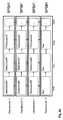
- FIG. 8ashows that each DependencyID corresponding to the base layer and the plurality of enhancement layers is provided with an individual sequence parameter set SPS.
- the encoding method in accordance with the present inventiondetects if the sequence parameter sets for different DependencyId's are equal and uses only one SPS for coding. In this example only SPS 1 is used for encoding of all the enhancement layers.
Landscapes
- Engineering & Computer Science (AREA)
- Multimedia (AREA)
- Signal Processing (AREA)
- Compression Or Coding Systems Of Tv Signals (AREA)
Description
- The present invention relates to the field of video encoding and decoding, and more specifically to scalable video data processing.
- Conventional video coding standards (e.g. MPEG-1, H.261/263/264) incorporate motion estimation and motion compensation to remove temporal redundancies between video frames. These concepts are very familiar for skilled readers with a basic understanding of video coding, and will not be described in detail.
- The working draft 1.0 of the scalable extension to H.264/AVC [JVT: "Scalable video working draft", JVT-N020, 5 February 2005] currently enables coding of multiple scalable layers with different values of dependency identifications (DependencyId). Accordingly each layer comprises a dependency identification and, for a coded video sequence, respectively a certain sequence parameter set (SPS). A coded video sequence consists of successive coded pictures from an instantaneous decoding refresh (IDR) picture to the next IDR picture, exclusively. Any picture that succeeds an IDR picture in decoding order shall not use inter prediction reference from prior to the IDR picture in decoding order. The sequence parameter set includes among other things data which will be used on the decoder side for a proper decoding operation.
- There are two main disadvantages associated with the current coding methods according to the present state of the art. First, if a scalable presentation point with
- DependencyId equal to 7 is desired, and all the lower layers with DependencyId equal to 0 to 6 are required, then at least 8 sequence parameter sets have to be transmitted for the presentation or decoding operation, respectively. However, if no SPS parameters other than the seq_parameter_id need to be changed which is possible if the spatial resolutions equal for all layers, then those certain and substantially identical SPSs are actually redundantly transmitted. Since SPSs are typically transmitted in the session beginning in a reliable and out-of-band way, reception acknowledgements are needed and retransmission may be used. Thus, increased amount of data to be sent means longer session setup delay, which is unwanted for the end user experience.
- A second disadvantage relates to flexibility and coding efficiency. The maximum number of initial SPSs is 32. If a scalable presentation point with DependencyId equal to 7 is desired, and all the lower layers with DependencyID equal to 0 to 6 are required, then in average coding the layer(s) of each value of DependencyId may have at most only 4 SPS variations. Therefore the flexibility and possibly also coding efficiency is lowered compared to that 32 SPS variations could have been used. Updating an SPS during a video session could solve this problem. However, during a video transport session SPS updating may easily cause problem because of loss of the synchronization between the updated SPS and those NAL units referencing it. In addition, if the update is done using the in-band way, e.g. transmitted using Real-time Transport Protocol (RTP) together with the coded video slices, it may get lost.
- The object of the present invention is to provide a methodology, a device, and a system for efficiently encoding or decoding, respectively which overcomes the above mentioned problems of the state of the art and provides an effective coding avoiding redundancies.
- The objects of the present invention are solved by the subject matter defined in the accompanying independent claims.
- According to one aspect of the present inventive operation the constraint that a sequence parameter set (SPS) is activated for each value of DependencyId may be removed. Rather, a new SPS is activated only when it is needed. A new sequence is only needed when at least one SPS parameter other than seq_parameter_set_id change is required. The invention may be used in any application that applies scalable video coding, wherein one or more sequence parameter sets are used for coding.
- The main advantages reside in that sequence parameter sets can be used more efficiently such that the initial session setup delay is reduced and more sequence parameter sets can be used for a certain scalable layer such that the scalable layer can be encoded in a more flexible way and improved coding efficiency due to the flexibility is also attained.
- The encoding/decoding methods and operations according to the present invention are specified, only for the sake of simplicity, for one coded video sequence, but an adaptation for multiple coded video sequences is contemplated within the scope of the present invention.
- According to a first aspect of the present invention, a method for scalable encoding of video data is provided as specified in
claim 1. The novel feature with respect to [1] is that a number of base and enhancement layers having different values for dependency identifiers are encoded using the same sequence parameter set. - According to the inventive operation of the present invention, reuse of a certain sequence parameter set in scalable layers with different values of DependencyId is enabled.
- According to a preferred embodiment generating of said base layer and said at least one enhancement layer is based on motion information within said video data, said motion information being provided by a motion estimation process.
- According to a preferred embodiment said sequence parameter set (SPS) comprises an SPS identifier, said SPS identifier being referred to by picture parameter set further referred in a slice header. Thereby exact identification of certain SPS within a plurality of sequence parameter sets is enabled
- According to a preferred embodiment said DependencyID's for at least two of the group of said base layer and at least one enhancement layer are the same.
- According to a preferred embodiment said SPS further comprises at least one of the group comprising profile information, level information, chroma format information, picture size information and frame crop information.
- According to another aspect of the present invention, a method for decoding scalable encoded video data is provided as specified in
claim 3. - According to another aspect of the present invention there is also provided an encoding device, operative according to a method for encoding as above.
- According to another aspect of the present invention there is also provided a decoding device, operative according to a method for decoding as above.
- According to another aspect of the present invention there is also provided a computer program product comprising a computer readable storage structure embodying computer program code thereon for execution by a computer processor hosted by an electronic device, wherein said computer program code comprises instructions for performing a method for encoding as above.
- Advantages of the present invention will become apparent to the reader of the present invention when reading the detailed description referring to embodiments of the present invention, based on which the inventive concept is easily understandable.
- Throughout the detailed description and the accompanying drawings the same or similar components, units, or devices will be referenced by same reference numerals for clarity purposes.
- It shall be noted that the designations portable device and mobile device are used synonymously throughout the description.
- The accompanying drawings are included to provide a further understanding of the invention, and are incorporated in and constitute a part of this specification. The drawings illustrate embodiments of the present invention and together with the description serve to explain the principles of the invention. In the drawings,
Fig. 1 schematically illustrates an example block diagram for a portable CE device embodied exemplarily on the basis of a cellular terminal device;Fig. 2 is a general principle of scalable coding and decoding of video data according the state of the art;Fig. 3 depicts an operational sequence showing the encoding side in accordance with the present invention;Fig. 4 depicts an operational sequence showing the decoding side in accordance with the present invention;Fig. 5a is a detailed illustration of the encoding principle in accordance with the present invention;Fig. 5b is a detailed illustration of the decoding principle in accordance with the present invention;Fig. 6 represents the encoding apparatus in accordance with the present invention showing all components;Fig. 7 represents the decoding apparatus in accordance with the present invention showing all components;Fig. 8a shows an implementation for encoding video data, wherein each DependencyID receives an SPS;Fig. 8b shows an implementation for encoding video data, wherein one certain SPS is used for coding in accordance with the present invention.- Even though the invention is described above with reference to embodiments according to the accompanying drawings, it is clear that the invention is not restricted thereto but it can be modified in several ways within the scope of the appended claims.
- In the following description of the various embodiments, reference is made to the accompanying drawings which form a part thereof, and in which is shown by way of illustration various embodiments in which the invention may be practiced. It is to be understood that other embodiments may be utilized and structural and functional modifications may be made without departing from the scope of the invention. Wherever possible same reference numbers are used throughout drawings and description to refer to similar or like parts.
Fig. 1 depicts a typical mobile device according to an embodiment of the present invention. The mobile device 10 shown inFig. 1 is capable for cellular data and voice communications. It should be noted that the present invention is not limited to this specific embodiment, which represents for the way of illustration one embodiment out of a multiplicity of embodiments. The mobile device 10 includes a (main) microprocessor ormicrocontroller 100 as well as components associated with the microprocessor controlling the operation of the mobile device. These components include adisplay controller 130 connecting to adisplay module 135, anon-volatile memory 140, avolatile memory 150 such as a random access memory (RAM), an audio input/output (I/O)interface 160 connecting to amicrophone 161, aspeaker 162 and/or aheadset 163, akeypad controller 170 connected to akeypad 175 or keyboard, any auxiliary input/output (I/O)interface 200, and a short-range communications interface 180. Such a device also typically includes other device subsystems shown generally at 190.- The mobile device 10 may communicate over a voice network and/or may likewise communicate over a data network, such as any public land mobile networks (PLMNs) in form of e.g. digital cellular networks, especially GSM (global system for mobile communication) or UMTS (universal mobile telecommunications system). Typically the voice and/or data communication is operated via an air interface, i.e. a cellular communication interface subsystem in cooperation with further components (see above) to a base station (BS) or node B (not shown) being part of a radio access network (RAN) of the infrastructure of the cellular network. The cellular communication interface subsystem as depicted illustratively with reference to
Fig. 1 comprises thecellular interface 110, a digital signal processor (DSP) 120, a receiver (RX) 121, a transmitter (TX) 122, and one or more local oscillators (LOs) 123 and enables the communication with one or more public land mobile networks (PLMNs). The digital signal processor (DSP) 120 sends communication signals 124 to the transmitter (TX) 122 and receives communication signals 125 from the receiver (RX) 121. In addition to processing communication signals, thedigital signal processor 120 also provides for receiver control signals 126 andtransmitter control signal 127. For example, besides the modulation and demodulation of the signals to be transmitted and signals received, respectively, the gain levels applied to communication signals in the receiver (RX) 121 and transmitter (TX) 122 may be adaptively controlled through automatic gain control algorithms implemented in the digital signal processor (DSP) 120. Other transceiver control algorithms could also be implemented in the digital signal processor (DSP) 120 in order to provide more sophisticated control of thetransceiver 122. In case the mobile device 10 communications through the PLMN occur at a single frequency or a closely-spaced set of frequencies, then a single local oscillator (LO) 128 may be used in conjunction with the transmitter (TX) 122 and receiver (RX) 121. Alternatively, if different frequencies are utilized for voice/ data communications or transmission versus reception, then a plurality of local oscillators 128 can be used to generate a plurality of corresponding frequencies. Although theantenna 129 depicted inFIG. 1 or a diversity antenna system could be used (not shown), the mobile device 10 could be used with a single antenna structure for signal reception as well as transmission. Information, which includes both voice and data information, is communicated to and from thecellular interface 110 via a data link between the digital signal processor (DSP) 120. The detailed design of thecellular interface 110, such as frequency band, component selection, power level, etc., will be dependent upon the wireless network in which themobile device 100 is intended to operate. - After any required network registration or activation procedures, which may involve the subscriber identification module (SIM) 210 required for registration in cellular networks, have been completed, the mobile device 10 may then send and receive communication signals, including both voice and data signals, over the wireless network. Signals received by the
antenna 129 from the wireless network are routed to thereceiver 121, which provides for such operations as signal amplification, frequency down conversion, filtering, channel selection, and analog to digital conversion. Analog to digital conversion of a received signal allows more complex communication functions, such as digital demodulation and decoding, to be performed using the digital signal processor (DSP) 120. In a similar manner, signals to be transmitted to the network are processed, including modulation and encoding, for example, by the digital signal processor (DSP) 120 and are then provided to thetransmitter 122 for digital to analog conversion, frequency up conversion, filtering, amplification, and transmission to the wireless network via theantenna 129. - The microprocessor / microcontroller (µC) 110, which may also be designated as a device platform microprocessor, manages the functions of the mobile device 10.
Operating system software 149 used by theprocessor 110 is preferably stored in a persistent store such as thenon-volatile memory 140, which may be implemented, for example, as a Flash memory, battery backed-up RAM, any other non-volatile storage technology, or any combination thereof. In addition to theoperating system 149, which controls low-level functions as well as (graphical) basic user interface functions of the mobile device 10, thenon-volatile memory 140 includes a plurality of high-level software application programs or modules, such as a voice communication software application 142, a datacommunication software application 141, an organizer module (not shown), or any other type of software module (not shown). These modules are executed by theprocessor 100 and provide a high-level interface between a user of the mobile device 10 and the mobile device 10. This interface typically includes a graphical component provided through thedisplay 135 controlled by adisplay controller 130 and input/output components provided through akeypad 175 connected via akeypad controller 170 to theprocessor 100, an auxiliary input/output (I/O)interface 200, and/or a short-range (SR)communication interface 180. The auxiliary I/O interface 200 comprises especially a USB (universal serial bus) interface, serial interface, MMC (multimedia card) interface and related interface technologies/standards, and any other standardized or proprietary data communication bus technology, whereas the short-range communication interface may be a radio frequency (RF) low-power interface including especially WLAN (wireless local area network) and Bluetooth communication technology or an IRDA (infrared data access) interface. The RF low-power interface technology referred to herein should especially be understood to include any IEEE 801.xx standard technology, which description is obtainable from the Institute of Electrical and Electronics Engineers. Moreover, the auxiliary I/O interface 200 as well as the short-range communication interface 180 may each represent one or more interfaces supporting one or more input/output interface technologies and communication interface technologies, respectively. The operating system, specific device software applications or modules, or parts thereof, may be temporarily loaded into avolatile store 150 such as a random access memory (typically implemented on the basis of DRAM (direct random access memory) technology for faster operation. Moreover, received communication signals may also be temporarily stored tovolatile memory 150, before permanently writing them to a file system located in thenon-volatile memory 140 or any mass storage preferably detachably connected via the auxiliary I/O interface for storing data. It should be understood that the components described above represent typical components of a traditional mobile device 10 embodied herein in form of a cellular phone. The present invention is not limited to these specific components and their implementation depicted merely for the way for illustration and sake of completeness. - An exemplary software application module of the mobile device 10 is a personal information manager application providing PDA functionality including typically a contact manager, calendar, a task manager, and the like. Such a personal information manager is executed by the
processor 100, may have access to the components of the mobile device 10, and may interact with other software application modules. For instance, interaction with the voice communication software application allows for managing phone calls, voice mails, etc., and interaction with the data communication software application enables for managing SMS (short message service), MMS (multimedia service), e-mail communications and other data transmissions. Thenon-volatile memory 140 preferably provides a file system to facilitate permanent storage of data items on the device including particularly calendar entries, contacts etc. The ability for data communication with networks, e.g. via the cellular interface, the short-range communication interface, or the auxiliary I/O interface enables upload, download, and synchronization via such networks. - The
application modules 141 to 149 represent device functions or software applications that are configured to be executed by theprocessor 100. In most known mobile devices, a single processor manages and controls the overall operation of the mobile device as well as all device functions and software applications. Such a concept is applicable for today's mobile devices. Especially the implementation of enhanced multimedia functionalities includes for example reproducing of video streaming applications, manipulating of digital images, and video sequences captured by integrated or detachably connected digital camera functionality but also gaming applications with sophisticated graphics drives the requirement of computational power. One way to deal with the requirement for computational power, which has been pursued in the past, solves the problem for increasing computational power by implementing powerful and universal processor cores. Another approach for providing computational power is to implement two or more independent processor cores, which is a well known methodology in the art. The advantages of several independent processor cores can be immediately appreciated by those skilled in the art. Whereas a universal processor is designed for carrying out a multiplicity of different tasks without specialization to a pre-selection of distinct tasks, a multi-processor arrangement may include one or more universal processors and one or more specialized processors adapted for processing a predefined set of tasks. Nevertheless, the implementation of several processors within one device, especially a mobile device such as mobile device 10, requires traditionally a complete and sophisticated redesign of the components. - In the following, the present invention will provide a concept which allows simple integration of additional processor cores into an existing processing device implementation enabling the omission of expensive complete and sophisticated redesign. The inventive concept will be described with reference to system-on-a-chip (SoC) design. System-on-a-chip (SoC) is a concept of integrating at least numerous (or all) components of a processing device into a single high-integrated chip. Such a system-on-a-chip can contain digital, analog, mixed-signal, and often radio-frequency functions - all on one chip. A typical processing device comprises a number of integrated circuits that perform different tasks. These integrated circuits may include especially microprocessor, memory, universal asynchronous receiver-transmitters (UARTs), serial/parallel ports, direct memory access (DMA) controllers, and the like. A universal asynchronous receiver-transmitter (UART) translates between parallel bits of data and serial bits. The recent improvements in semiconductor technology caused by very-large-scale integration (VLSI) integrated circuits enable a significant growth in complexity, making it possible to integrate numerous components of a system in a single chip. With reference to
Fig. 1 , one or more components thereof, e.g. thecontrollers memory components interfaces processor 100 in a signal chip which forms finally a system-on-a-chip (Soc). - Additionally, said device 10 is equipped with a module for
scalable encoding 105 and decoding 106 of video data according to the inventive operation of the present invention. By means of theCPU 100 saidmodules - A very general principle of (layered) scalable coding and decoding is shown in
Fig. 2 , where by supplementing further building blocks of the intermediate-level type (highlighted by a dotted rectangle), an arbitrary number of scalable layers can in principle be realized. The spatiotemporal signal resolution to be represented by the base layer is first generated by decimation (preprocessing). In the subsequent encoding stage, an appropriate setting of the quantizer will then lead to a certain overall quality level of the base information. - The base-layer reconstruction is an approximation of all the higher layer resolution levels and can be utilized in the decoding of the subsequent layers. The midprocessing unit performs up-sampling of the next lower layer signal to the subsequent layer's resolution. Typically, preprocessing and midprocessing are performed by decimation and interpolation throughout all stages, whereas the particular action to be taken can be quite different depending on the dimension of scalability, e.g., motion-compensated processing can be implemented for frame-rate up-sampling in temporal scalability. The information is propagated from the lower into the higher resolution layers both during encoding and decoding. In all types of scalability (temporal, spatial, or quantization/quality), the constraints imposed by the frame-recursive processing of hybrid video coding have to be carefully considered. The base layer and any composition from layers should in the ideal case be self-contained, which means that the prediction should not use any decoded information from higher layers. Otherwise, different estimates would be used at the encoder and decoder sides, and a drift effect would occur. The prediction of the base-layer information will, however, always be worse than it could be if all enhancement layer information was allowed in the prediction. This does not penalize the operation of the coder at the base layer, which will implicitly perform like a single-layer coder at the same rate; however, as the base-layer information is used for prediction of the enhancement layer, the rate-distortion performance toward higher rates will be worse than it could be in a single-layer coder.
Fig. 3 shows an operational sequence of the encoding method in accordance with the present invention. In an operational operation S300 the sequence may be started. This may correspond for instance to the receiving of a video data stream from a camera or the like. Said camera may be incorporated within the above mentioned device 10. After obtaining S310 said video data stream the encoder may generate or create, respectively the corresponding base layer (BL) and its enhancement layers (EL), as shown according to the operational operation S320. It is imaginable to implement only one EL but creating of more EL results in better encoding and thereby further increased decoding quality.- After generating the base layer and also the enhancement layers an operation S330 follows corresponding to generating of the corresponding dependency identifications (DependencyID) of the BL and EL as well. The value of the DependencyID will increase if more then one enhancement layer will be used.
- In an operation S340, determining the respective sequence parameter set (SPS) for each of said base layer and all said enhancement layers is provided, wherein for a number of base or enhancement layers if the selected SPS parameters are substantially equal, only one SPS is used. According to the inventive operation of the present invention only one SPS may be used for different DependencyId values resulting in effective encoding operation because redundant data will be removed. After determining said SPS which shall be used, the encoding operation S350 will start. In this operation the base layer and enhancement layers and also optional information like motion vectors or the like are multiplexed resulting in a bit stream, or encoded video data stream which is now ready for further processing.
- If no operations follow, the operational sequence will come to an end S390 and may be restarted according to a new iteration or if for instance a no raw video data sequence is to be encoded. However, said resulting encoded video data stream may be sent to a receiver which may be adapted to decode or store said data. The decoding process will be nearly described with reference to
fig. 4 in the following. Fig. 4 depicts an encoding operational sequence in accordance with the present invention. After receiving of scalable encoded video data the operational sequence starts S400. After obtaining S410 said encode video data, the base layer and the corresponding one or more enhancement layers may be identified according the operational operation S420. This means that the received and encoded video data stream will be demultiplexed and accordingly divided in BL, and EL and optionally additional information like motion vectors (MV) or the like. On the basis of the received data stream the DependencyID will be detected and also the sequence parameter set (SPS) which shall be used will be identified. In an operational operation S450, decoding of said scalable encoded data will be provided under consideration of the previously determined information: BL, SPS and EL.- If no further operations are needed, the method will come to end according to the operation S490 and may be restarted if necessary.
Fig. 5a shows the principle of the scalable encoding process in accordance with the present invention. All processing may be supported by a motion estimator which is depicted with reference tofig. 5a . The motion estimator uses the video data for generating motion vectors which are further necessary for encoding or picture improvement.- The original video data is used for generating motion vectors and also for generating the base layer BL and the corresponding plurality of enhancement layers EL. The enhancement layers may be generated on the basis of the original video data, on the BL and also optionally on the basis of the information delivered by the motion vectors. For further processing it is imaginable that the motion vectors are also encoded or combined, respectively within the scalable encoded video data stream to perform picture improvement or the like on the decoder side.
- Each BL or EL is provided with a DependencyID and with an SPS. In accordance with the inventive operation of the present invention the encoder first determine SPSs to be used and checks if the SPS parameters of any subset of all the base layers and enhancement layers are substantially equal and will use only one SPS for encoding of the subset of layers to avoid redundant further data traffic.
Fig. 5a shows a possible detailed embodiment of thescalable encoding module 105 in accordance with the present invention. Fig. 5b illustrates a decoder of scalable encoded video data in accordance with the present invention.Fig. 5b is a possible embodiment of thedecoding module 106 adapted to process scalable encode video data.- Actually, the module for determining the appropriate SPS is not needed on the decoding side as it is needed on the encoding side. For the sake of completeness the determining module is also shown with reference to
figure 5b . In formation on which SPS is used in a picture it is signaled by referencing its ID in the picture parameter set, and the picture parameter set ID is further referenced in the slice header. - On the basis of the received data the EL stream, the DependencyId's and the BL stream are identified which is symbolized by a demultiplexer DEMUX. The achieved data streams are now ready for further processing provided by the corresponding EL-Decoder and the BL-decoder. Each of the depicted modules is adapted to interact with each other if needed. The motion vectors are available and shall be used for decoding. According to the used SPS the decoder provides proper decoding resulting in scalable decoded video data.
- It is also imaginable that the BL data stream will also be provided as a separate data stream for a certain implementation. The BL data, which is also decoded, may be used if problems within the decoding procedure of the EL's were detected.
Fig. 6 represents the encoding module in accordance with the present invention showing all components needed for encoding. Said module forscalable encoding 105 of video data, comprises: a component for obtaining 610 said video data, a component for generating 620 a base layer based on said obtained video data, a component for generating 630 a predetermined number of corresponding scalable enhancement layers based on said video data and said base layer, a component for generating 640 a dependency identification (DependencyID) for each of said base or enhancement layers, said dependency identifications having subsequent reference numerals, a component for determining 650 the respective sequence parameter set (SPS) for each of said base or enhancement layers, wherein for a number of base or enhancement layers if the selected SPS parameters are substantially equal, only one SPS is used, and a component for encoding 660 said base layer and said enhancement layers by using said respective sequence parameter set.Fig. 7 represents the decoding module in accordance with the present invention showing all components needed for decoding. Said module for decoding 105 scalable encoded video data, comprises: a component for obtaining 710 said encoded video data, a component for identifying 720 a base layer and a plurality of enhancement layers within said encoded video data, a component for detecting 730 a dependency identification (DependencyID) for each of said enhancement layers, said dependency identifications having subsequent reference numerals and for at least two layers with different said dependency identifications a same SPS may be used, and a component for decoding 740 said base layer and said decoded enhancement layers by using said used sequence parameter set.- Both
modules - The
figures 8a and8b illustrate the main difference between the scalable encoding method of the state of the art and the method in accordance with the present invention operation.Fig. 8a shows that each DependencyID corresponding to the base layer and the plurality of enhancement layers is provided with an individual sequence parameter set SPS. In opposition to that the encoding method in accordance with the present invention detects if the sequence parameter sets for different DependencyId's are equal and uses only one SPS for coding. In this example onlySPS 1 is used for encoding of all the enhancement layers. - Even though the invention is described above with reference to embodiments according to the accompanying drawings, it is clear that the invention is not restricted thereto but it can be modified in several ways within the scope of the appended claims.
Claims (10)
- A method comprising:encoding video into a scalable bitstream bygenerating (320) a base layer and a plurality of enhancement layers;generating (330) dependency identifiers for said base layer and the plurality of enhancement layers;providing an identifier for a picture parameter set in a slice header for each of said base and enhancement layers having different values for dependency identifiers, wherein the picture parameter set comprises an identifier referencing a sequence parameter set; andencoding (350) the base and the enhancement layers using said sequence parameter set for each layer, wherein a number of base or enhancement layers having different values for dependency identifiers are encoded using the same sequence parameter set.
- The method according to claim 1, wherein said sequence parameter set comprises at least one of the group comprising profile information, level information, chroma format information, picture size information and frame crop information.
- A method comprising:decoding an encoded scalable video bitstream byreceiving (410, 420) a base layer and a plurality of enhancement layers from the encoded scalable video bitstream;decoding (430) dependency identifiers for said base layer and the plurality of enhancement layers;receiving at least one sequence parameter set;receiving an identifier for a picture parameter set in a slice header for each of said base and enhancement layers having different values for dependency identifiers, wherein the picture parameter set comprises an identifier referencing a sequence parameter set; anddecoding (450) the base and the enhancement layers using said referenced sequence parameter set for each layer, wherein a number of base or enhancement layers having different values for dependency identifiers are decoded using the parameter values from the same sequence parameter set.
- The method of claim 3, wherein said sequence parameter set comprises at least one of the group comprising profile information, level information, chroma format information, picture size information and frame crop information.
- A computer program product comprising a computer readable storage structure embodying computer program code thereon for execution by a computer processor, wherein said computer program code comprises instructions for performing a method of encoding video into a scalable bitstream according to claim 1.
- A computer program product comprising a computer readable storage structure embodying computer program code thereon for execution by a computer processor, wherein said computer program code comprises instructions for performing a method of decoding an encoded scalable video bitstream according to claim 3.
- An apparatus comprising:a base layer encoder for generating a base layer based on a video signal; andan enhancement layer encoder forgenerating a plurality of enhancement layers comprising a first enhancement layer and a second enhancement layer based on the video signal and the base layer;generating a first dependency identifier for said first enhancement layer and a second dependency identifier for said second enhancement layer, wherein a value of the second dependency identifier is different from a value of the first dependency identifier;wherein the base layer encoder and the enhancement layer encoder are arranged to determine a sequence parameter set for use for said base layer, said first enhancement layer and said second enhancement layer and provide an identifier for a picture parameter set in a slice header for each of said base and enhancement layers having different values for dependency identifiers, wherein the picture parameter set comprises an identifier referencing said sequence parameter set; andthe base layer encoder and/or the enhancement layer encoder are arranged to encode at least two of said base layer, said first enhancement layer and said second enhancement layer by using the same sequence parameter set.
- The apparatus according to claim 7, wherein said sequence parameter set comprises at least one of the group comprising profile information, level information, chroma format information, pictures size information and frame crop information.
- An apparatus comprising:a base layer decoder for decoding a base layer of encoded scalable video bitstream; andan enhancement layer decoder forreceiving a plurality of enhancement layers from the encoded scalable video bitstream;wherein the base layer decoder and the enhancement layer decoder are arranged to decode dependency identifiers for said base layer and the plurality of enhancement layers and receive at least one sequence parameter setwherein the enhancement layer decoder is arranged to receive, in a slice header, an identifier for a picture parameter set for each of said base and enhancement layers having different values for dependency identifiers, wherein the picture parameter set comprises an identifier referencing a sequence parameter set;the base layer decoder and/or the enhancement layer decoder are arranged to decode the base and the enhancement layers using said referenced sequence parameter set for each layer, wherein a number of base or enhancement layers having different values for dependency identifiers are decoded using the parameter values from the same sequence parameter set.
- The apparatus according to claim 9, wherein said sequence parameter set comprises at least one of the group comprising profile information, level information, chroma format information, picture size information and frame crop information.
Applications Claiming Priority (2)
| Application Number | Priority Date | Filing Date | Title |
|---|---|---|---|
| US67121305P | 2005-04-13 | 2005-04-13 | |
| PCT/IB2006/000648WO2006109117A1 (en) | 2005-04-13 | 2006-03-23 | Method, device and system for effectively coding and decoding of video data |
Publications (3)
| Publication Number | Publication Date |
|---|---|
| EP1869888A1 EP1869888A1 (en) | 2007-12-26 |
| EP1869888A4 EP1869888A4 (en) | 2013-09-11 |
| EP1869888B1true EP1869888B1 (en) | 2016-07-06 |
Family
ID=37086632
Family Applications (1)
| Application Number | Title | Priority Date | Filing Date |
|---|---|---|---|
| EP06710582.5AActiveEP1869888B1 (en) | 2005-04-13 | 2006-03-23 | Method, device and system for effectively coding and decoding of video data |
Country Status (12)
| Country | Link |
|---|---|
| US (1) | US8259800B2 (en) |
| EP (1) | EP1869888B1 (en) |
| JP (1) | JP4903195B2 (en) |
| KR (1) | KR100931870B1 (en) |
| CN (1) | CN101180883B (en) |
| AU (1) | AU2006233279C1 (en) |
| BR (1) | BRPI0610398B1 (en) |
| MX (1) | MX2007012604A (en) |
| MY (1) | MY145660A (en) |
| RU (1) | RU2377735C2 (en) |
| TW (1) | TWI383682B (en) |
| WO (1) | WO2006109117A1 (en) |
Families Citing this family (52)
| Publication number | Priority date | Publication date | Assignee | Title |
|---|---|---|---|---|
| JP2004291740A (en)* | 2003-03-26 | 2004-10-21 | Nsk Ltd | Steering device |
| KR20070038396A (en)* | 2005-10-05 | 2007-04-10 | 엘지전자 주식회사 | Method of encoding and decoding video signal |
| CN101317460A (en) | 2005-10-11 | 2008-12-03 | 诺基亚公司 | Systems and methods for efficient scalable stream adaptation |
| KR100825743B1 (en)* | 2005-11-15 | 2008-04-29 | 한국전자통신연구원 | A method of scalable video coding for varying spatial scalability of bitstream in real time and a codec using the same |
| AU2007342468B2 (en)* | 2007-01-05 | 2011-11-24 | Interdigital Vc Holdings, Inc. | Hypothetical reference decoder for scalable video coding |
| EP3484123A1 (en)* | 2007-01-12 | 2019-05-15 | University-Industry Cooperation Group Of Kyung Hee University | Packet format of network abstraction layer unit, and algorithm and apparatus for video encoding and decoding using the format |
| KR20080093386A (en)* | 2007-04-16 | 2008-10-21 | 한국전자통신연구원 | Color video stretching and decoding method and apparatus therefor |
| CN103338367B (en)* | 2007-04-18 | 2017-08-29 | 杜比国际公司 | Coding and decoding methods |
| AU2012238298B2 (en)* | 2007-04-18 | 2015-04-16 | Dolby International Ab | Coding systems |
| US20090003431A1 (en)* | 2007-06-28 | 2009-01-01 | Lihua Zhu | Method for encoding video data in a scalable manner |
| AU2015203559B2 (en)* | 2007-04-18 | 2017-08-10 | Dolby International Ab | Coding systems |
| US20140072058A1 (en) | 2010-03-05 | 2014-03-13 | Thomson Licensing | Coding systems |
| KR20080114388A (en)* | 2007-06-27 | 2008-12-31 | 삼성전자주식회사 | Scalable video encoding apparatus and method and video decoding apparatus and method |
| JP5339697B2 (en)* | 2007-08-14 | 2013-11-13 | キヤノン株式会社 | Transmission device, transmission method, and computer program |
| KR100912826B1 (en)* | 2007-08-16 | 2009-08-18 | 한국전자통신연구원 | A enhancement layer encoder/decoder for improving a voice quality in G.711 codec and method therefor |
| EP2345191B1 (en) | 2008-08-08 | 2019-02-13 | InterDigital Patent Holdings, Inc. | Mac reset and reconfiguration |
| KR101118265B1 (en) | 2008-11-05 | 2012-03-22 | 한국전자통신연구원 | Method and Apparatus for providing the variable bit-rate service |
| KR101597987B1 (en)* | 2009-03-03 | 2016-03-08 | 삼성전자주식회사 | Hierarchical Independent Residual Image Multilayer Coding Apparatus and Method |
| EP2536150B1 (en) | 2010-02-09 | 2017-09-13 | Nippon Telegraph And Telephone Corporation | Predictive coding method for motion vector, predictive decoding method for motion vector, video coding device, video decoding device, and programs therefor |
| KR20140089596A (en)* | 2010-02-09 | 2014-07-15 | 니폰덴신뎅와 가부시키가이샤 | Predictive coding method for motion vector, predictive decoding method for motion vector, video coding device, video decoding device, and programs therefor |
| US8896715B2 (en) | 2010-02-11 | 2014-11-25 | Microsoft Corporation | Generic platform video image stabilization |
| TWI419568B (en)* | 2010-05-27 | 2013-12-11 | Univ Nat Sun Yat Sen | Three dimensional image dividing method |
| US9769230B2 (en)* | 2010-07-20 | 2017-09-19 | Nokia Technologies Oy | Media streaming apparatus |
| CN102123299B (en)* | 2011-01-11 | 2012-11-28 | 中国联合网络通信集团有限公司 | Playing method and device of telescopic video |
| RU2014103489A (en) | 2011-07-02 | 2015-08-10 | Самсунг Электроникс Ко., Лтд. | METHOD AND DEVICE FOR MULTIPLEXING AND DEMULTIPLEXING VIDEO DATA TO IDENTIFY THE PLAYBACK STATUS OF VIDEO DATA |
| US9824426B2 (en) | 2011-08-01 | 2017-11-21 | Microsoft Technology Licensing, Llc | Reduced latency video stabilization |
| US9451284B2 (en) | 2011-10-10 | 2016-09-20 | Qualcomm Incorporated | Efficient signaling of reference picture sets |
| KR20130116782A (en) | 2012-04-16 | 2013-10-24 | 한국전자통신연구원 | Scalable layer description for scalable coded video bitstream |
| US10491913B2 (en)* | 2012-04-24 | 2019-11-26 | Telefonaktiebolaget L M Ericsson (Publ) | Identifying a parameter set for decoding a multi-layer video representation |
| US9161004B2 (en)* | 2012-04-25 | 2015-10-13 | Qualcomm Incorporated | Identifying parameter sets in video files |
| US9451256B2 (en)* | 2012-07-20 | 2016-09-20 | Qualcomm Incorporated | Reusing parameter sets for video coding |
| WO2014051396A1 (en)* | 2012-09-27 | 2014-04-03 | 한국전자통신연구원 | Method and apparatus for image encoding/decoding |
| US9432664B2 (en) | 2012-09-28 | 2016-08-30 | Qualcomm Incorporated | Signaling layer identifiers for operation points in video coding |
| US9462268B2 (en) | 2012-10-09 | 2016-10-04 | Cisco Technology, Inc. | Output management of prior decoded pictures at picture format transitions in bitstreams |
| EP2907308B1 (en) | 2012-10-09 | 2019-08-14 | Cisco Technology, Inc. | Providing a common set of parameters for sub-layers of coded video |
| US10021388B2 (en) | 2012-12-26 | 2018-07-10 | Electronics And Telecommunications Research Institute | Video encoding and decoding method and apparatus using the same |
| CN104904214A (en)* | 2013-01-07 | 2015-09-09 | Vid拓展公司 | Motion information signaling for scalable video coding |
| KR20140092198A (en) | 2013-01-07 | 2014-07-23 | 한국전자통신연구원 | Video Description for Scalable Coded Video Bitstream |
| WO2014162750A1 (en)* | 2013-04-05 | 2014-10-09 | Sharp Kabushiki Kaisha | Random access point pictures |
| US10070140B2 (en)* | 2013-04-08 | 2018-09-04 | Hfi Innovation Inc. | Method and apparatus for quantization matrix signaling and representation in scalable video coding |
| EP3522540B1 (en) | 2013-06-18 | 2025-04-16 | InterDigital VC Holdings, Inc. | Inter-layer parameter set for hevc extensions |
| US9648326B2 (en)* | 2013-07-02 | 2017-05-09 | Qualcomm Incorporated | Optimizations on inter-layer prediction signalling for multi-layer video coding |
| WO2015005331A1 (en)* | 2013-07-10 | 2015-01-15 | シャープ株式会社 | Image decoding device and image encoding device |
| JP5886341B2 (en) | 2014-03-07 | 2016-03-16 | ソニー株式会社 | Transmitting apparatus, transmitting method, receiving apparatus, and receiving method |
| US10880565B2 (en) | 2014-03-24 | 2020-12-29 | Qualcomm Incorporated | Use of specific HEVC SEI messages for multi-layer video codecs |
| WO2016021365A1 (en)* | 2014-08-07 | 2016-02-11 | ソニー株式会社 | Transmission device, transmission method and reception device |
| CN106034260B (en)* | 2015-03-17 | 2019-08-09 | 上海交通大学 | Signaling and mechanism supporting layered transmission |
| EP3119086A1 (en)* | 2015-07-17 | 2017-01-18 | Thomson Licensing | Methods and devices for encoding/decoding videos |
| GB2554877B (en)* | 2016-10-10 | 2021-03-31 | Canon Kk | Methods, devices, and computer programs for improving rendering display during streaming of timed media data |
| US20180352240A1 (en)* | 2017-06-03 | 2018-12-06 | Apple Inc. | Generalized Temporal Sub-Layering Frame Work |
| BR112022018463A2 (en)* | 2020-03-17 | 2023-02-23 | Huawei Tech Co Ltd | ENCODER, DECODER AND CORRESPONDING METHODS |
| CN116189310B (en)* | 2022-11-16 | 2024-01-23 | 北京理工大学 | Method for providing human motion data set and electronic equipment |
Family Cites Families (12)
| Publication number | Priority date | Publication date | Assignee | Title |
|---|---|---|---|---|
| US5852565A (en) | 1996-01-30 | 1998-12-22 | Demografx | Temporal and resolution layering in advanced television |
| US6173013B1 (en)* | 1996-11-08 | 2001-01-09 | Sony Corporation | Method and apparatus for encoding enhancement and base layer image signals using a predicted image signal |
| RU2201654C2 (en)* | 1997-12-23 | 2003-03-27 | Томсон Лайсенсинг С.А. | Low-noise coding and decoding method |
| US6501797B1 (en)* | 1999-07-06 | 2002-12-31 | Koninklijke Phillips Electronics N.V. | System and method for improved fine granular scalable video using base layer coding information |
| US6816194B2 (en)* | 2000-07-11 | 2004-11-09 | Microsoft Corporation | Systems and methods with error resilience in enhancement layer bitstream of scalable video coding |
| RU2231559C1 (en) | 2003-03-20 | 2004-06-27 | ООО "Сорби стил" | Direct method for alloying steel with complex of elements |
| US7860161B2 (en)* | 2003-12-15 | 2010-12-28 | Microsoft Corporation | Enhancement layer transcoding of fine-granular scalable video bitstreams |
| US7586924B2 (en)* | 2004-02-27 | 2009-09-08 | Fraunhofer-Gesellschaft Zur Foerderung Der Angewandten Forschung E.V. | Apparatus and method for coding an information signal into a data stream, converting the data stream and decoding the data stream |
| US20050259729A1 (en)* | 2004-05-21 | 2005-11-24 | Shijun Sun | Video coding with quality scalability |
| US20060013305A1 (en)* | 2004-07-14 | 2006-01-19 | Sharp Laboratories Of America, Inc. | Temporal scalable coding using AVC coding tools |
| DE102004059993B4 (en)* | 2004-10-15 | 2006-08-31 | Fraunhofer-Gesellschaft zur Förderung der angewandten Forschung e.V. | Apparatus and method for generating a coded video sequence using interlayer motion data prediction, and computer program and computer readable medium |
| KR20060122663A (en)* | 2005-05-26 | 2006-11-30 | 엘지전자 주식회사 | Method for transmitting and using picture information in a video signal encoding/decoding |
- 2006
- 2006-03-23BRBRPI0610398-7Apatent/BRPI0610398B1/enactiveIP Right Grant
- 2006-03-23MXMX2007012604Apatent/MX2007012604A/enactiveIP Right Grant
- 2006-03-23CNCN200680018046.XApatent/CN101180883B/enactiveActive
- 2006-03-23KRKR1020077026284Apatent/KR100931870B1/enactiveActive
- 2006-03-23RURU2007137805/09Apatent/RU2377735C2/enactive
- 2006-03-23JPJP2008505972Apatent/JP4903195B2/enactiveActive
- 2006-03-23AUAU2006233279Apatent/AU2006233279C1/enactiveActive
- 2006-03-23WOPCT/IB2006/000648patent/WO2006109117A1/enactiveApplication Filing
- 2006-03-23EPEP06710582.5Apatent/EP1869888B1/enactiveActive
- 2006-03-27USUS11/391,723patent/US8259800B2/enactiveActive
- 2006-03-29TWTW095110971Apatent/TWI383682B/enactive
- 2006-03-30MYMYPI20061439Apatent/MY145660A/enunknown
Also Published As
| Publication number | Publication date |
|---|---|
| AU2006233279B2 (en) | 2010-05-27 |
| HK1114522A1 (en) | 2008-10-31 |
| CN101180883A (en) | 2008-05-14 |
| TW200708109A (en) | 2007-02-16 |
| WO2006109117A1 (en) | 2006-10-19 |
| TWI383682B (en) | 2013-01-21 |
| CN101180883B (en) | 2016-02-03 |
| KR100931870B1 (en) | 2009-12-15 |
| BRPI0610398A2 (en) | 2012-01-10 |
| JP2008536425A (en) | 2008-09-04 |
| EP1869888A4 (en) | 2013-09-11 |
| MX2007012604A (en) | 2008-01-11 |
| AU2006233279C1 (en) | 2011-01-27 |
| EP1869888A1 (en) | 2007-12-26 |
| WO2006109117A8 (en) | 2007-12-27 |
| BRPI0610398A8 (en) | 2016-05-10 |
| US20060251169A1 (en) | 2006-11-09 |
| KR20080002951A (en) | 2008-01-04 |
| AU2006233279A1 (en) | 2006-10-19 |
| RU2377735C2 (en) | 2009-12-27 |
| RU2007137805A (en) | 2009-05-20 |
| MY145660A (en) | 2012-03-15 |
| JP4903195B2 (en) | 2012-03-28 |
| BRPI0610398B1 (en) | 2019-07-02 |
| US8259800B2 (en) | 2012-09-04 |
Similar Documents
| Publication | Publication Date | Title |
|---|---|---|
| EP1869888B1 (en) | Method, device and system for effectively coding and decoding of video data | |
| US20060256863A1 (en) | Method, device and system for enhanced and effective fine granularity scalability (FGS) coding and decoding of video data | |
| US20070201551A1 (en) | System and apparatus for low-complexity fine granularity scalable video coding with motion compensation | |
| US20080240242A1 (en) | Method and system for motion vector predictions | |
| US20070009050A1 (en) | Method and apparatus for update step in video coding based on motion compensated temporal filtering | |
| US20070110159A1 (en) | Method and apparatus for sub-pixel interpolation for updating operation in video coding | |
| US20070053441A1 (en) | Method and apparatus for update step in video coding using motion compensated temporal filtering | |
| US20090279602A1 (en) | Method, Device and System for Effective Fine Granularity Scalability (FGS) Coding and Decoding of Video Data | |
| US20070201550A1 (en) | Method and apparatus for entropy coding in fine granularity scalable video coding | |
| HK1114522B (en) | Method, device and system for effectively coding and decoding of video data | |
| HK1115257A (en) | Method, device and system for effective fine granularity scalability (fgs) coding and decoding of video data |
Legal Events
| Date | Code | Title | Description |
|---|---|---|---|
| PUAI | Public reference made under article 153(3) epc to a published international application that has entered the european phase | Free format text:ORIGINAL CODE: 0009012 | |
| 17P | Request for examination filed | Effective date:20071008 | |
| AK | Designated contracting states | Kind code of ref document:A1 Designated state(s):AT BE BG CH CY CZ DE DK EE ES FI FR GB GR HU IE IS IT LI LT LU LV MC NL PL PT RO SE SI SK TR | |
| DAX | Request for extension of the european patent (deleted) | ||
| A4 | Supplementary search report drawn up and despatched | Effective date:20130809 | |
| RIC1 | Information provided on ipc code assigned before grant | Ipc:H04N 7/24 20110101ALI20130805BHEP Ipc:H04N 7/26 20060101AFI20130805BHEP | |
| RAP1 | Party data changed (applicant data changed or rights of an application transferred) | Owner name:NOKIA CORPORATION | |
| 17Q | First examination report despatched | Effective date:20140702 | |
| RAP1 | Party data changed (applicant data changed or rights of an application transferred) | Owner name:NOKIA TECHNOLOGIES OY | |
| REG | Reference to a national code | Ref country code:DE Ref legal event code:R079 Ref document number:602006049518 Country of ref document:DE Free format text:PREVIOUS MAIN CLASS: H04N0007260000 Ipc:H04N0007240000 | |
| GRAP | Despatch of communication of intention to grant a patent | Free format text:ORIGINAL CODE: EPIDOSNIGR1 | |
| RIC1 | Information provided on ipc code assigned before grant | Ipc:H04N 19/172 20140101ALI20160108BHEP Ipc:H04N 19/187 20140101ALI20160108BHEP Ipc:H04N 19/46 20140101ALI20160108BHEP Ipc:H04N 7/24 20060101AFI20160108BHEP Ipc:H04N 19/70 20140101ALI20160108BHEP Ipc:H04N 19/30 20140101ALI20160108BHEP Ipc:H04N 19/105 20140101ALI20160108BHEP | |
| INTG | Intention to grant announced | Effective date:20160202 | |
| GRAS | Grant fee paid | Free format text:ORIGINAL CODE: EPIDOSNIGR3 | |
| GRAA | (expected) grant | Free format text:ORIGINAL CODE: 0009210 | |
| AK | Designated contracting states | Kind code of ref document:B1 Designated state(s):AT BE BG CH CY CZ DE DK EE ES FI FR GB GR HU IE IS IT LI LT LU LV MC NL PL PT RO SE SI SK TR | |
| REG | Reference to a national code | Ref country code:GB Ref legal event code:FG4D | |
| RIN1 | Information on inventor provided before grant (corrected) | Inventor name:WANG, YE-KUI | |
| REG | Reference to a national code | Ref country code:AT Ref legal event code:REF Ref document number:811423 Country of ref document:AT Kind code of ref document:T Effective date:20160715 Ref country code:CH Ref legal event code:EP | |
| REG | Reference to a national code | Ref country code:IE Ref legal event code:FG4D | |
| REG | Reference to a national code | Ref country code:DE Ref legal event code:R096 Ref document number:602006049518 Country of ref document:DE | |
| REG | Reference to a national code | Ref country code:NL Ref legal event code:FP | |
| REG | Reference to a national code | Ref country code:LT Ref legal event code:MG4D | |
| REG | Reference to a national code | Ref country code:AT Ref legal event code:MK05 Ref document number:811423 Country of ref document:AT Kind code of ref document:T Effective date:20160706 | |
| PG25 | Lapsed in a contracting state [announced via postgrant information from national office to epo] | Ref country code:FI Free format text:LAPSE BECAUSE OF FAILURE TO SUBMIT A TRANSLATION OF THE DESCRIPTION OR TO PAY THE FEE WITHIN THE PRESCRIBED TIME-LIMIT Effective date:20160706 Ref country code:IT Free format text:LAPSE BECAUSE OF FAILURE TO SUBMIT A TRANSLATION OF THE DESCRIPTION OR TO PAY THE FEE WITHIN THE PRESCRIBED TIME-LIMIT Effective date:20160706 Ref country code:LT Free format text:LAPSE BECAUSE OF FAILURE TO SUBMIT A TRANSLATION OF THE DESCRIPTION OR TO PAY THE FEE WITHIN THE PRESCRIBED TIME-LIMIT Effective date:20160706 Ref country code:IS Free format text:LAPSE BECAUSE OF FAILURE TO SUBMIT A TRANSLATION OF THE DESCRIPTION OR TO PAY THE FEE WITHIN THE PRESCRIBED TIME-LIMIT Effective date:20161106 | |
| PG25 | Lapsed in a contracting state [announced via postgrant information from national office to epo] | Ref country code:PL Free format text:LAPSE BECAUSE OF FAILURE TO SUBMIT A TRANSLATION OF THE DESCRIPTION OR TO PAY THE FEE WITHIN THE PRESCRIBED TIME-LIMIT Effective date:20160706 Ref country code:PT Free format text:LAPSE BECAUSE OF FAILURE TO SUBMIT A TRANSLATION OF THE DESCRIPTION OR TO PAY THE FEE WITHIN THE PRESCRIBED TIME-LIMIT Effective date:20161107 Ref country code:BE Free format text:LAPSE BECAUSE OF FAILURE TO SUBMIT A TRANSLATION OF THE DESCRIPTION OR TO PAY THE FEE WITHIN THE PRESCRIBED TIME-LIMIT Effective date:20160706 Ref country code:ES Free format text:LAPSE BECAUSE OF FAILURE TO SUBMIT A TRANSLATION OF THE DESCRIPTION OR TO PAY THE FEE WITHIN THE PRESCRIBED TIME-LIMIT Effective date:20160706 Ref country code:LV Free format text:LAPSE BECAUSE OF FAILURE TO SUBMIT A TRANSLATION OF THE DESCRIPTION OR TO PAY THE FEE WITHIN THE PRESCRIBED TIME-LIMIT Effective date:20160706 Ref country code:GR Free format text:LAPSE BECAUSE OF FAILURE TO SUBMIT A TRANSLATION OF THE DESCRIPTION OR TO PAY THE FEE WITHIN THE PRESCRIBED TIME-LIMIT Effective date:20161007 Ref country code:AT Free format text:LAPSE BECAUSE OF FAILURE TO SUBMIT A TRANSLATION OF THE DESCRIPTION OR TO PAY THE FEE WITHIN THE PRESCRIBED TIME-LIMIT Effective date:20160706 Ref country code:SE Free format text:LAPSE BECAUSE OF FAILURE TO SUBMIT A TRANSLATION OF THE DESCRIPTION OR TO PAY THE FEE WITHIN THE PRESCRIBED TIME-LIMIT Effective date:20160706 | |
| REG | Reference to a national code | Ref country code:DE Ref legal event code:R097 Ref document number:602006049518 Country of ref document:DE | |
| PG25 | Lapsed in a contracting state [announced via postgrant information from national office to epo] | Ref country code:EE Free format text:LAPSE BECAUSE OF FAILURE TO SUBMIT A TRANSLATION OF THE DESCRIPTION OR TO PAY THE FEE WITHIN THE PRESCRIBED TIME-LIMIT Effective date:20160706 Ref country code:RO Free format text:LAPSE BECAUSE OF FAILURE TO SUBMIT A TRANSLATION OF THE DESCRIPTION OR TO PAY THE FEE WITHIN THE PRESCRIBED TIME-LIMIT Effective date:20160706 | |
| PLBE | No opposition filed within time limit | Free format text:ORIGINAL CODE: 0009261 | |
| STAA | Information on the status of an ep patent application or granted ep patent | Free format text:STATUS: NO OPPOSITION FILED WITHIN TIME LIMIT | |
| PG25 | Lapsed in a contracting state [announced via postgrant information from national office to epo] | Ref country code:CZ Free format text:LAPSE BECAUSE OF FAILURE TO SUBMIT A TRANSLATION OF THE DESCRIPTION OR TO PAY THE FEE WITHIN THE PRESCRIBED TIME-LIMIT Effective date:20160706 Ref country code:SK Free format text:LAPSE BECAUSE OF FAILURE TO SUBMIT A TRANSLATION OF THE DESCRIPTION OR TO PAY THE FEE WITHIN THE PRESCRIBED TIME-LIMIT Effective date:20160706 Ref country code:DK Free format text:LAPSE BECAUSE OF FAILURE TO SUBMIT A TRANSLATION OF THE DESCRIPTION OR TO PAY THE FEE WITHIN THE PRESCRIBED TIME-LIMIT Effective date:20160706 Ref country code:BG Free format text:LAPSE BECAUSE OF FAILURE TO SUBMIT A TRANSLATION OF THE DESCRIPTION OR TO PAY THE FEE WITHIN THE PRESCRIBED TIME-LIMIT Effective date:20161006 | |
| 26N | No opposition filed | Effective date:20170407 | |
| PG25 | Lapsed in a contracting state [announced via postgrant information from national office to epo] | Ref country code:SI Free format text:LAPSE BECAUSE OF FAILURE TO SUBMIT A TRANSLATION OF THE DESCRIPTION OR TO PAY THE FEE WITHIN THE PRESCRIBED TIME-LIMIT Effective date:20160706 | |
| REG | Reference to a national code | Ref country code:CH Ref legal event code:PL | |
| PG25 | Lapsed in a contracting state [announced via postgrant information from national office to epo] | Ref country code:MC Free format text:LAPSE BECAUSE OF FAILURE TO SUBMIT A TRANSLATION OF THE DESCRIPTION OR TO PAY THE FEE WITHIN THE PRESCRIBED TIME-LIMIT Effective date:20160706 | |
| REG | Reference to a national code | Ref country code:IE Ref legal event code:MM4A | |
| REG | Reference to a national code | Ref country code:FR Ref legal event code:ST Effective date:20171130 | |
| PG25 | Lapsed in a contracting state [announced via postgrant information from national office to epo] | Ref country code:LU Free format text:LAPSE BECAUSE OF NON-PAYMENT OF DUE FEES Effective date:20170323 Ref country code:FR Free format text:LAPSE BECAUSE OF NON-PAYMENT OF DUE FEES Effective date:20170331 | |
| PG25 | Lapsed in a contracting state [announced via postgrant information from national office to epo] | Ref country code:IE Free format text:LAPSE BECAUSE OF NON-PAYMENT OF DUE FEES Effective date:20170323 Ref country code:CH Free format text:LAPSE BECAUSE OF NON-PAYMENT OF DUE FEES Effective date:20170331 Ref country code:LI Free format text:LAPSE BECAUSE OF NON-PAYMENT OF DUE FEES Effective date:20170331 | |
| PG25 | Lapsed in a contracting state [announced via postgrant information from national office to epo] | Ref country code:HU Free format text:LAPSE BECAUSE OF FAILURE TO SUBMIT A TRANSLATION OF THE DESCRIPTION OR TO PAY THE FEE WITHIN THE PRESCRIBED TIME-LIMIT; INVALID AB INITIO Effective date:20060323 | |
| PG25 | Lapsed in a contracting state [announced via postgrant information from national office to epo] | Ref country code:CY Free format text:LAPSE BECAUSE OF NON-PAYMENT OF DUE FEES Effective date:20160706 | |
| PG25 | Lapsed in a contracting state [announced via postgrant information from national office to epo] | Ref country code:TR Free format text:LAPSE BECAUSE OF FAILURE TO SUBMIT A TRANSLATION OF THE DESCRIPTION OR TO PAY THE FEE WITHIN THE PRESCRIBED TIME-LIMIT Effective date:20160706 | |
| P01 | Opt-out of the competence of the unified patent court (upc) registered | Effective date:20230527 | |
| PGFP | Annual fee paid to national office [announced via postgrant information from national office to epo] | Ref country code:NL Payment date:20250217 Year of fee payment:20 | |
| PGFP | Annual fee paid to national office [announced via postgrant information from national office to epo] | Ref country code:DE Payment date:20250204 Year of fee payment:20 | |
| PGFP | Annual fee paid to national office [announced via postgrant information from national office to epo] | Ref country code:GB Payment date:20250130 Year of fee payment:20 |