EP1869809B1 - Gaming console wireless protocol for peripheral devices - Google Patents
Gaming console wireless protocol for peripheral devicesDownload PDFInfo
- Publication number
- EP1869809B1 EP1869809B1EP06751796.1AEP06751796AEP1869809B1EP 1869809 B1EP1869809 B1EP 1869809B1EP 06751796 AEP06751796 AEP 06751796AEP 1869809 B1EP1869809 B1EP 1869809B1
- Authority
- EP
- European Patent Office
- Prior art keywords
- data
- packet
- voice
- upstream
- wireless
- Prior art date
- Legal status (The legal status is an assumption and is not a legal conclusion. Google has not performed a legal analysis and makes no representation as to the accuracy of the status listed.)
- Not-in-force
Links
- 230000002093peripheral effectEffects0.000titledescription6
- 238000011144upstream manufacturingMethods0.000claimsdescription30
- 238000000034methodMethods0.000claimsdescription16
- 238000012937correctionMethods0.000claimsdescription7
- 238000001228spectrumMethods0.000claimsdescription3
- 238000012545processingMethods0.000description14
- 230000005540biological transmissionEffects0.000description8
- 238000004891communicationMethods0.000description5
- 230000008569processEffects0.000description3
- 230000008859changeEffects0.000description2
- 238000001514detection methodMethods0.000description2
- 230000006870functionEffects0.000description2
- 230000006855networkingEffects0.000description2
- 238000007792additionMethods0.000description1
- 238000010276constructionMethods0.000description1
- 125000004122cyclic groupChemical group0.000description1
- 230000001419dependent effectEffects0.000description1
- 238000010586diagramMethods0.000description1
- 230000036039immunityEffects0.000description1
- 230000010354integrationEffects0.000description1
- 238000012986modificationMethods0.000description1
- 230000004048modificationEffects0.000description1
- 230000002035prolonged effectEffects0.000description1
- 230000035945sensitivityEffects0.000description1
- 238000012360testing methodMethods0.000description1
Images


Classifications
- A—HUMAN NECESSITIES
- A63—SPORTS; GAMES; AMUSEMENTS
- A63F—CARD, BOARD, OR ROULETTE GAMES; INDOOR GAMES USING SMALL MOVING PLAYING BODIES; VIDEO GAMES; GAMES NOT OTHERWISE PROVIDED FOR
- A63F13/00—Video games, i.e. games using an electronically generated display having two or more dimensions
- A63F13/20—Input arrangements for video game devices
- H—ELECTRICITY
- H04—ELECTRIC COMMUNICATION TECHNIQUE
- H04B—TRANSMISSION
- H04B1/00—Details of transmission systems, not covered by a single one of groups H04B3/00 - H04B13/00; Details of transmission systems not characterised by the medium used for transmission
- H04B1/69—Spread spectrum techniques
- H04B1/713—Spread spectrum techniques using frequency hopping
- H—ELECTRICITY
- H04—ELECTRIC COMMUNICATION TECHNIQUE
- H04L—TRANSMISSION OF DIGITAL INFORMATION, e.g. TELEGRAPHIC COMMUNICATION
- H04L1/00—Arrangements for detecting or preventing errors in the information received
- H04L1/004—Arrangements for detecting or preventing errors in the information received by using forward error control
- H—ELECTRICITY
- H04—ELECTRIC COMMUNICATION TECHNIQUE
- H04L—TRANSMISSION OF DIGITAL INFORMATION, e.g. TELEGRAPHIC COMMUNICATION
- H04L1/00—Arrangements for detecting or preventing errors in the information received
- H04L1/12—Arrangements for detecting or preventing errors in the information received by using return channel
- H04L1/16—Arrangements for detecting or preventing errors in the information received by using return channel in which the return channel carries supervisory signals, e.g. repetition request signals
- H04L1/18—Automatic repetition systems, e.g. Van Duuren systems
- H04L1/1812—Hybrid protocols; Hybrid automatic repeat request [HARQ]
- H—ELECTRICITY
- H04—ELECTRIC COMMUNICATION TECHNIQUE
- H04W—WIRELESS COMMUNICATION NETWORKS
- H04W28/00—Network traffic management; Network resource management
- H04W28/02—Traffic management, e.g. flow control or congestion control
- H04W28/04—Error control
- H—ELECTRICITY
- H04—ELECTRIC COMMUNICATION TECHNIQUE
- H04W—WIRELESS COMMUNICATION NETWORKS
- H04W80/00—Wireless network protocols or protocol adaptations to wireless operation
- A—HUMAN NECESSITIES
- A63—SPORTS; GAMES; AMUSEMENTS
- A63F—CARD, BOARD, OR ROULETTE GAMES; INDOOR GAMES USING SMALL MOVING PLAYING BODIES; VIDEO GAMES; GAMES NOT OTHERWISE PROVIDED FOR
- A63F13/00—Video games, i.e. games using an electronically generated display having two or more dimensions
- A63F13/20—Input arrangements for video game devices
- A63F13/23—Input arrangements for video game devices for interfacing with the game device, e.g. specific interfaces between game controller and console
- A63F13/235—Input arrangements for video game devices for interfacing with the game device, e.g. specific interfaces between game controller and console using a wireless connection, e.g. infrared or piconet
- A—HUMAN NECESSITIES
- A63—SPORTS; GAMES; AMUSEMENTS
- A63F—CARD, BOARD, OR ROULETTE GAMES; INDOOR GAMES USING SMALL MOVING PLAYING BODIES; VIDEO GAMES; GAMES NOT OTHERWISE PROVIDED FOR
- A63F13/00—Video games, i.e. games using an electronically generated display having two or more dimensions
- A63F13/30—Interconnection arrangements between game servers and game devices; Interconnection arrangements between game devices; Interconnection arrangements between game servers
- A63F13/35—Details of game servers
- A63F13/358—Adapting the game course according to the network or server load, e.g. for reducing latency due to different connection speeds between clients
- A—HUMAN NECESSITIES
- A63—SPORTS; GAMES; AMUSEMENTS
- A63F—CARD, BOARD, OR ROULETTE GAMES; INDOOR GAMES USING SMALL MOVING PLAYING BODIES; VIDEO GAMES; GAMES NOT OTHERWISE PROVIDED FOR
- A63F13/00—Video games, i.e. games using an electronically generated display having two or more dimensions
- A63F13/40—Processing input control signals of video game devices, e.g. signals generated by the player or derived from the environment
- A63F13/42—Processing input control signals of video game devices, e.g. signals generated by the player or derived from the environment by mapping the input signals into game commands, e.g. mapping the displacement of a stylus on a touch screen to the steering angle of a virtual vehicle
- A63F13/424—Processing input control signals of video game devices, e.g. signals generated by the player or derived from the environment by mapping the input signals into game commands, e.g. mapping the displacement of a stylus on a touch screen to the steering angle of a virtual vehicle involving acoustic input signals, e.g. by using the results of pitch or rhythm extraction or voice recognition
- A—HUMAN NECESSITIES
- A63—SPORTS; GAMES; AMUSEMENTS
- A63F—CARD, BOARD, OR ROULETTE GAMES; INDOOR GAMES USING SMALL MOVING PLAYING BODIES; VIDEO GAMES; GAMES NOT OTHERWISE PROVIDED FOR
- A63F2300/00—Features of games using an electronically generated display having two or more dimensions, e.g. on a television screen, showing representations related to the game
- A63F2300/10—Features of games using an electronically generated display having two or more dimensions, e.g. on a television screen, showing representations related to the game characterized by input arrangements for converting player-generated signals into game device control signals
- A63F2300/1025—Features of games using an electronically generated display having two or more dimensions, e.g. on a television screen, showing representations related to the game characterized by input arrangements for converting player-generated signals into game device control signals details of the interface with the game device, e.g. USB version detection
- A63F2300/1031—Features of games using an electronically generated display having two or more dimensions, e.g. on a television screen, showing representations related to the game characterized by input arrangements for converting player-generated signals into game device control signals details of the interface with the game device, e.g. USB version detection using a wireless connection, e.g. Bluetooth, infrared connections
- A—HUMAN NECESSITIES
- A63—SPORTS; GAMES; AMUSEMENTS
- A63F—CARD, BOARD, OR ROULETTE GAMES; INDOOR GAMES USING SMALL MOVING PLAYING BODIES; VIDEO GAMES; GAMES NOT OTHERWISE PROVIDED FOR
- A63F2300/00—Features of games using an electronically generated display having two or more dimensions, e.g. on a television screen, showing representations related to the game
- A63F2300/50—Features of games using an electronically generated display having two or more dimensions, e.g. on a television screen, showing representations related to the game characterized by details of game servers
- A63F2300/53—Features of games using an electronically generated display having two or more dimensions, e.g. on a television screen, showing representations related to the game characterized by details of game servers details of basic data processing
- A63F2300/534—Features of games using an electronically generated display having two or more dimensions, e.g. on a television screen, showing representations related to the game characterized by details of game servers details of basic data processing for network load management, e.g. bandwidth optimization, latency reduction
- A—HUMAN NECESSITIES
- A63—SPORTS; GAMES; AMUSEMENTS
- A63F—CARD, BOARD, OR ROULETTE GAMES; INDOOR GAMES USING SMALL MOVING PLAYING BODIES; VIDEO GAMES; GAMES NOT OTHERWISE PROVIDED FOR
- A63F2300/00—Features of games using an electronically generated display having two or more dimensions, e.g. on a television screen, showing representations related to the game
- A63F2300/60—Methods for processing data by generating or executing the game program
- A63F2300/6063—Methods for processing data by generating or executing the game program for sound processing
- A63F2300/6072—Methods for processing data by generating or executing the game program for sound processing of an input signal, e.g. pitch and rhythm extraction, voice recognition
- H—ELECTRICITY
- H04—ELECTRIC COMMUNICATION TECHNIQUE
- H04L—TRANSMISSION OF DIGITAL INFORMATION, e.g. TELEGRAPHIC COMMUNICATION
- H04L1/00—Arrangements for detecting or preventing errors in the information received
- H04L1/12—Arrangements for detecting or preventing errors in the information received by using return channel
- H04L1/16—Arrangements for detecting or preventing errors in the information received by using return channel in which the return channel carries supervisory signals, e.g. repetition request signals
- H04L1/18—Automatic repetition systems, e.g. Van Duuren systems
- H04L1/1867—Arrangements specially adapted for the transmitter end
- H—ELECTRICITY
- H04—ELECTRIC COMMUNICATION TECHNIQUE
- H04L—TRANSMISSION OF DIGITAL INFORMATION, e.g. TELEGRAPHIC COMMUNICATION
- H04L1/00—Arrangements for detecting or preventing errors in the information received
- H04L2001/0092—Error control systems characterised by the topology of the transmission link
- H04L2001/0093—Point-to-multipoint
- H—ELECTRICITY
- H04—ELECTRIC COMMUNICATION TECHNIQUE
- H04W—WIRELESS COMMUNICATION NETWORKS
- H04W88/00—Devices specially adapted for wireless communication networks, e.g. terminals, base stations or access point devices
- H04W88/02—Terminal devices
- H04W88/04—Terminal devices adapted for relaying to or from another terminal or user
Definitions
- This inventiongenerally relates to the field of gaming and multimedia devices.
- the present inventionis directed to a wireless protocol used to communicate data and voice information between a gaming device and wireless peripheral accessories.
- EP 1 133 094teaches that in wireless communication arrangements that utilize a transmission period of time followed by a retransmission period of time, the utilization and effectiveness of retransmission communications can be increased by dynamically assigning desired communications to respective retransmission time slots of the retransmission period.
- US 6 684 062discloses a wireless system for video game control comprising a base transceiver engaged with an electronic game device where said base transceiver communicates wirelessly with one or more wireless controllers concurrently and which implements a variety of techniques to achieve significant advantages in the areas of latency, reliability, power consumption, and cross platform compatibility.
- US 6 775 254discloses techniques for transmitting voice/data and packet data services such that packet data transmissions have less impact on voice/data transmissions. Voice/data and packet data are multiplexed within a transmission interval such that the available resources are efficiently utilized.
- the present inventionprovides a method for communicating voice and data between a gaming console and one of a plurality of wireless accessories using a wireless protocol, along with a wireless accessory configured to perform the method, as defined by the appended independent claims.
- Optional featuresare set out in the dependent claims.
- the upstream and downstream voice and data packetseach comprise an RF setup field, a preamble field, a sync field, a header field, a data field, and an error correction field.
- the voice datamay be communicated in the downstream voice packet to a plurality of voice-enabled devices.
- a plurality of downstream voice packetsmay be communicated in the downlink sub frame.
- a downlink retransmission packetmay be rebroadcast to a plurality of wireless accessories.
- Fig. 1illustrates the functional components of a multimedia console 100 in which certain aspects of the present invention may be implemented.
- the multimedia console 100has a central processing unit (CPU) 101 having a level 1 cache 102, a level 2 cache 104, and a flash ROM (Read Only Memory) 106.
- the level 1 cache 102 and a level 2 cache 104temporarily store data and hence reduce the number of memory access cycles, thereby improving processing speed and throughput.
- the CPU 101may be provided having more than one core, and thus, additional level 1 and level 2 caches 102 and 104.
- the flash ROM 106may store executable code that is loaded during an initial phase of a boot process when the multimedia console 100 is powered ON.
- a graphics processing unit (GPU) 108 and a video encoder/video codec (coder/decoder) 114form a video processing pipeline for high speed and high resolution graphics processing. Data is carried from the graphics processing unit 108 to the video encoder/video codec 114 via a bus. The video processing pipeline outputs data to an A/V (audio/video) port 140 for transmission to a television or other display.
- a memory controller 110is connected to the GPU 108 to facilitates processor access to various types of memory 112, such as, but not limited to, a RAM (Random Access Memory).
- the multimedia console 100includes an I/O controller 120, a system management controller 122, an audio processing unit 123, a network interface controller 124, a first USB host controller 126, a second USB controller 128 and a front panel I/O subassembly 130 that are preferably implemented on a module 118.
- the USB controllers 126 and 128serve as hosts for peripheral controllers 142(1)-142(2), a wireless adapter 148, and an external memory device 146 (e.g., flash memory, external CD/DVD ROM drive, removable media, etc.).
- the network interface 124 and/or wireless adapter 148provide access to a network (e.g., the Internet, home network, etc.) and may be any of a wide variety of various wired or wireless adapter components including an Ethernet card, a modem, a Bluetooth module, a cable modem, and the like.
- a networke.g., the Internet, home network, etc.
- wired or wireless adapter componentsincluding an Ethernet card, a modem, a Bluetooth module, a cable modem, and the like.
- System memory 143is provided to store application data that is loaded during the boot process.
- a media drive 144is provided and may comprise a DVD/CD drive, hard drive, or other removable media drive, etc.
- the media drive 144may be internal or external to the multimedia console 100.
- Application datamay be accessed via the media drive 144 for execution, playback, etc. by the multimedia console 100.
- the media drive 144is connected to the I/O controller 120 via a bus, such as a Serial ATA bus or other high speed connection (e.g., IEEE 1394).
- the system management controller 122provides a variety of service functions related to assuring availability of the multimedia console 100.
- the audio processing unit 123 and an audio codec 132form a corresponding audio processing pipeline with high fidelity and stereo processing. Audio data is carried between the audio processing unit 123 and the audio codec 132 via a communication link.
- the audio processing pipelineoutputs data to the A/V port 140 for reproduction by an external audio player or device having audio capabilities.
- the front panel I/O subassembly 130supports the functionality of the power button 150 and the eject button 152, as well as any LEDs (light emitting diodes) or other indicators exposed on the outer surface of the multimedia console 100.
- a system power supply module 136provides power to the components of the multimedia console 100.
- a fan 138cools the circuitry within the multimedia console 100.
- the CPU 101, GPU 108, memory controller 110, and various other components within the multimedia console 100are interconnected via one or more buses, including serial and parallel buses, a memory bus, a peripheral bus, and a processor or local bus using any of a variety of bus architectures.
- bus architecturescan include a Peripheral Component Interconnects (PCI) bus, PCI-Express bus, etc.
- application datamay be loaded from the system memory 143 into memory 112 and/or caches 102, 104 and executed on the CPU 101.
- the applicationmay present a graphical user interface that provides a consistent user experience when navigating to different media types available on the multimedia console 100.
- applications and/or other media contained within the media drive 144may be launched or played from the media drive 144 to provide additional functionalities to the multimedia console 100.
- the multimedia console 100may be operated as a standalone system by simply connecting the system to a television or other display. In this standalone mode, the multimedia console 100 allows one or more users to interact with the system, watch movies, or listen to music. However, with the integration of broadband connectivity made available through the network interface 124 or the wireless adapter 148, the multimedia console 100 may further be operated as a participant in a larger network community.
- a set amount of hardware resourcesare reserved for system use by the multimedia console operating system. These resources may include a reservation of memory (e.g., 16MB), CPU and GPU cycles (e.g., 5%), networking bandwidth (e.g., 8 kbs), etc. Because these resources are reserved at system boot time, the reserved resources do not exist from the application's view.
- the memory reservationpreferably is large enough to contain the launch kernel, concurrent system applications and drivers.
- the CPU reservationis preferably constant such that if the reserved CPU usage is not used by the system applications, an idle thread will consume any unused cycles.
- lightweight messages generated by the system applicationsare displayed by using a GPU interrupt to schedule code to render popup into an overlay.
- the amount of memory required for an overlaydepends on the overlay area size and the overlay preferably scales with screen resolution. Where a full user interface is used by the concurrent system application, it is preferable to use a resolution independent of application resolution. A scaler may be used to set this resolution such that the need to change frequency and cause a TV resynch is eliminated.
- the multimedia console 100boots and system resources are reserved, concurrent system applications execute to provide system functionalities.
- the system functionalitiesare encapsulated in a set of system applications that execute within the reserved system resources described above.
- the operating system kernelidentifies threads that are system application threads versus gaming application threads.
- the system applicationsare preferably scheduled to run on the CPU 101 at predetermined times and intervals in order to provide a consistent system resource view to the application. The scheduling is to minimize cache disruption for the gaming application running on the console.
- a multimedia console application managercontrols the gaming application audio level (e.g., mute, attenuate) when system applications are active.
- Input devicesare shared by gaming applications and system applications.
- the input devicesare not reserved resources, but are to be switched between system applications and the gaming application such that each will have a focus of the device.
- the application managerpreferably controls the switching of input stream, without knowledge the gaming application's knowledge and a driver maintains state information regarding focus switches.
- the console 100may be configured having two different radio subsystems.
- the first wireless systemis an 802.11b/g standard compliant module (WiFi) within the network interface 124, which is used for wireless home network connectivity via an access point 156. This can be used in place of a standard Ethernet connection to add wireless networking ability to access the Internet or remote PC's.
- the secondis a frequency-hopping spread spectrum (FHSS), low transmit power system within the wireless adapter 148 operating within the Industrial-Scientific-Medical (ISM) 2.4 GHz band.
- the wireless adapter 148provides wireless connectivity of various peripherals and devices (e.g., a wireless accessory 154) which can be used to operate the games.
- Fig. 3illustrates an overall framework of the protocol.
- the protocol 200is a TDMA system through which the host (e.g., console 100) and device (e.g., accessory 154) switch between transmitting and receiving based on a fixed time interval shown as T frame .
- the protocol 200enables up to eight accessories (four data and four voice) to simultaneously communicate to the console 100.
- the protocol 200provides for a mix of error correction and the use of frequency hopping techniques to provide for robust communication with minimal latency.
- the protocol 200is divided into three sub frames, upstream data packets 202-208, downstream data packets 210-214 and retransmission packets 216-218. Each will be described in greater detail below.
- Fig. 4there is illustrated the frame structure of the protocol 200 in the time domain. Inside each frame, there are 9 slots where the frequency allocation for each slot is shown in Table 1, below.
- nrepresents the entry for the current frame in the FHSS sequence
- F(n)is the channel that is mapped to this entry n and therefore the channel selected for this frame.
- the F(n+1)+20represents a channel that is 20 channels away from channel F(n+1).
- each accessory and/or voice-enabled devicereceives and transmits packets in a similar fashion, however at its appropriate time slot in accordance with the TDMA structure of the protocol 200. As such, the following description will be made with reference to accessory 1, but it applies to each of accessories 2-4, as shown in Fig. 4 .
- accessory 1may transmit data and voice sub packets 222 and 224.
- accessory 1may transmit data in a data sub packet, and a separate voice-enabled device may transmit voice in a voice sub packet during the time slot.
- Accessory 1(or voice-enabled device) will receive a voice data packet 226 at time slot F(n+1).
- the console 100will broadcast a data packet 228 to all devices at time slot F(n+1).
- the data packetwill be rebroadcast as data packet 232 at time slot F(n+1)+20.
- accessory 1may rebroadcast its data sub packet as data sub packet 230. This preferably done only if data sub packet 222 is not acknowledged by the console 100 in the data broadcast packet 228.
- An optional RF Setup field 234enables the host/device transceiver to switch from one mode (transmit/receive) to the other (receive/transmit) or change the transceiver frequency for frequency hopping.
- a preamble field 236 and synchronization field 238are used by the receiver within the accessory for clock and packet synchronization of the radio link. For example, 32-bit prolonged preamble transmissions may be used in combination with a preamble switched antenna instant receiver selection diversity algorithm implemented at the receiving end. This algorithm implies that the receiver during the first part of the preamble makes a first link quality estimate using one antenna, and during a second part makes a second estimate using the other antenna, and then, for the rest of the packet, selects the antenna which gave the highest quality estimate.
- a sync field 238is used by the receiving device to synchronize with the transmitting frequency and phase.
- a header field 240contains the information needed for data payload field that follows the header.
- the data payload field 242contains the information that is to be transmitted over the wireless interface. The length of this field is determined by type of the packet.
- the data packetis either error detectable or correctable based on the packet type using an error correction field 244.
- a cyclic redundancy code (CRC)may be used for detecting the packet error for voice packets, whereas forward error correction (FEC) is used for the data transmissions.
- FECforward error correction
- Reed-Solomon forward error correction algorithmmay be used here.
- the Reed-Solomon encodertakes the original data and adds extra "redundant" bits. Errors occur during the wireless transmission.
- the Reed-Solomon decoderprocesses the received data and attempts to correct errors and recover the original data. The number and type of errors that can be corrected depends on the characteristics of
- the wireless systemuses frequency hopping spread spectrum.
- a Pseudo-Random hopping sequencemay be used for the system.
- the sequence generationmay be based on a Maximum-Length Linear Feedback Shift Registers (ML-LFSR) method.
- Two channel allocation schemesmay be used in the wireless protocol 200.
- the first schemeis a frame based allocation and the second scheme is a slot based channel allocation.
- the 7 LSb out of the 19 bits of the M-sequenceare used for selecting the RF channel for each frame.
- Channel 7is selected.
- each channelhas to be equally accessed. This means that if the 7LSb of the hopping entry is greater than 122, this entry will be skipped and next entry will be used.
- the slot based channel selectionafter the channel for each frame is selected, inside each frame, there are 9 slots. The frequency allocation for each slot then made in accordance with Table 1, above.
- the upstream data packetsare the data packets sent by the accessories and devices 154 to console 100, and include the accessory data packets 202, 204, 206 and 208.
- the protocol 200supports up to 4 upstream data packets. Each data packet is sent at the predefined time slot ( Fig. 4 ) and contains both the device-specific data as well as the voice data.
- upstream data packet 204(also 202, 206 and 208) in greater detail. As illustrated, there are two sub packets inside each packet, one for data (246-258) and the other for voice (260-272). These correspond to, e.g., data sub packet 222 and voice sub packet 224 in Fig. 4 . Up to 4 upstream data packets are supported for up to 4 accessories and voice devices for a total of 8 devices.
- Each upstream data sub packet (246-258)contains three fields: a header 252, data body 254, and an FEC field 256.
- the header field 252contains the information about the accessory data field, dynamic power management and quality of service (QoS).
- the data field 254 formatmay be specified in a packet type field in the header 252 and may be that of Fig. 5 .
- the upstream data fieldcontains the data for the accessory 154 and a Plug-in Module (PMD) (i.e., a plug-in that may be connected to the accessory 154 to enhance its features).
- the FEC field 256may contain Reed-Solomon parity bytes. The parity bytes cover both the header and data fields of the upstream game controller sub packet.
- the upstream voice sub packet(260-272) contains three fields: a header field 266, a voice data field 268 and a CRC field 270.
- the header field 266indicates the types and properties of the voice data packet.
- the voice data field 268contains encoded voice data and link control data and may be structured as shown in Fig. 5 .
- the CRC field 270covers both the voice header field and the voice data field.
- the downstream sub frameincludes three packets: a voice downstream packet 210, a downlink data packet 212 and a voice downstream packet 214.
- a voice downstream packet 210contains system control information and is broadcasted to all the attached devices and accessories.
- a header field 280 of this packet 212contains the system control information to be broadcasted
- a data field 282contains control information for each device being addressed in the data packet 212. Thus, if four accessories are to be address, the data field 282 would be divided into four sub fields, each containing data for each device.
- the control informationmay contain details about flashing of LEDs on the accessory 154, motor control, feedback control, etc.
- the broadcast packetis protected by an FEC field 284 and is repeated automatically in every frame.
- a sliding field 286may be added at end of the downstream broadcast. It is preferable that the bits pattern have a minimum correlation with the preamble field and a pattern 0xC3C3 may be used here.
- the accessory receiverchecks the sliding field 286 in every broadcast packet received and tests for a packet sliding situation. If the accessory receiver detects sliding, it will set a bit in QoS and report it to host. Once sliding is detected, the detection party needs to stay on the current FHSS entry for the next frame to avoid the synchronization.
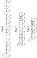
- Fig. 8there is illustrated an exemplary format of the downlink voice packets 210 and 214. These two packets 210 and 214 carry the downstream voice data for the four voice-enabled devices.
- the downlink voice packet 210contains the voice samples for device 1 and 2.
- the downlink voice packet 214contains the samples for device 3 and 4.
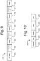
- the uplink retransmission packet 216This packet only re-transmits the accessory data, and only if an ACK bit in the broadcast packet 212 is not set for a particular accessory. This helps achieve a robust environment while reducing the power consumption of the accessory. If the above condition exists, the accessory will re-send its data and PMD data in the retransmission packet 216. The upstream voice data is not retransmitted in this packet. Since there is no ACK bit set in the broadcast retransmission packet, the same accessory packet will be re-transmitted again in the next frame if there is no new data available. If new accessory data is available, the accessory will send the new data packet instead.
- the broadcast retransmission packet 218is the repetition of the broadcast packet 212. It transmits the same information as in broadcast packet, but on a different carrier frequency (see, Fig. 4 ).
- a retransmit bit in the headeris set to 1 to indicate this is a broadcast retransmission packet.
- the ACK bit in the broadcast retransmission packetis NOT set or cleared based on the reception of the upstream re-transmission packet.
- the console 100preferably always transmits the broadcast retransmission packet. This is to improve the broadcast packet immunity to interference since the control data in the broadcast packet is critical for the wireless interface data exchange. However, an accessory may choose not to receive the retransmission packet based on the successfully reception of the first broadcast packet. This will help reduce the total power consumption for the accessory.
- the protocol of the present inventionprovides for a flexible environment where devices known and unknown may be enabled to communicate via the wireless link.
Landscapes
- Engineering & Computer Science (AREA)
- Computer Networks & Wireless Communication (AREA)
- Signal Processing (AREA)
- Multimedia (AREA)
- Human Computer Interaction (AREA)
- Mobile Radio Communication Systems (AREA)
- Small-Scale Networks (AREA)
- Time-Division Multiplex Systems (AREA)
Description
- This invention generally relates to the field of gaming and multimedia devices. In particular, the present invention is directed to a wireless protocol used to communicate data and voice information between a gaming device and wireless peripheral accessories.
- In gaming systems there is a strong demand for wireless controllers in order to eliminate the cabling found strung across so many living room floors. Existing wireless controllers are expensive and do not always provide a robust connection to the gaming device because of interference. Latency is another critical concern to gamers, as it is desirable that the wireless controller respond like a wired controller. In addition, there may be features in future gaming consoles that the wireless link must support. Developing a wireless game controller that meets these constraints would be greatly benefited by a protocol that enables multiple wireless devices to simultaneously communicate with the gaming device, while also providing for error correction and detection with minimal latency. The protocol should also be able to support new devices and functionalities as they become available.
EP 1 133 094US 6 684 062 discloses a wireless system for video game control comprising a base transceiver engaged with an electronic game device where said base transceiver communicates wirelessly with one or more wireless controllers concurrently and which implements a variety of techniques to achieve significant advantages in the areas of latency, reliability, power consumption, and cross platform compatibility.US 6 775 254 discloses techniques for transmitting voice/data and packet data services such that packet data transmissions have less impact on voice/data transmissions. Voice/data and packet data are multiplexed within a transmission interval such that the available resources are efficiently utilized.- Thus, there is a need for a system that overcomes these and other limitations in the prior art. There is also a need for the system to be cost efficient and effective. The present invention provides such a solution.
- The present invention provides a method for communicating voice and data between a gaming console and one of a plurality of wireless accessories using a wireless protocol, along with a wireless accessory configured to perform the method, as defined by the appended independent claims. Optional features are set out in the dependent claims.
- In accordance with another feature, the upstream and downstream voice and data packets each comprise an RF setup field, a preamble field, a sync field, a header field, a data field, and an error correction field. The voice data may be communicated in the downstream voice packet to a plurality of voice-enabled devices. In addition, a plurality of downstream voice packets may be communicated in the downlink sub frame.
- A downlink retransmission packet may be rebroadcast to a plurality of wireless accessories.
- Additional features and advantages of the invention will be made apparent from the following detailed description of illustrative embodiments that proceeds with reference to the accompanying drawings.
- The foregoing summary, as well as the following detailed description of preferred embodiments, is better understood when read in conjunction with the appended drawings. For the purpose of illustrating the invention, there is shown in the drawings exemplary constructions of the invention; however, the invention is not limited to the specific methods and instrumentalities disclosed. In the drawings:
Fig. 1 is a block diagram showing a gaming console in which aspects of the present invention may be implemented;Fig. 2 illustrates the console ofFig. 1 and radio sub-systems;Fig. 3 illustrates an overall framework of a protocol in accordance with the present invention;Fig. 4 illustrates a frame structure of the protocol ofFig. 3 in the time domain;Fig. 5 illustrates a format for data and voice packets;Fig. 6 illustrate an upstream data packet;Fig. 7 illustrates a downlink data packet;Fig. 8 illustrates a downlink voice packet; andFigs. 9 and 10 illustrate an uplink retransmission packet.Fig. 1 illustrates the functional components of amultimedia console 100 in which certain aspects of the present invention may be implemented. Themultimedia console 100 has a central processing unit (CPU) 101 having alevel 1cache 102, alevel 2cache 104, and a flash ROM (Read Only Memory) 106. Thelevel 1cache 102 and alevel 2cache 104 temporarily store data and hence reduce the number of memory access cycles, thereby improving processing speed and throughput. TheCPU 101 may be provided having more than one core, and thus,additional level 1 andlevel 2caches flash ROM 106 may store executable code that is loaded during an initial phase of a boot process when themultimedia console 100 is powered ON.- A graphics processing unit (GPU) 108 and a video encoder/video codec (coder/decoder) 114 form a video processing pipeline for high speed and high resolution graphics processing. Data is carried from the
graphics processing unit 108 to the video encoder/video codec 114 via a bus. The video processing pipeline outputs data to an A/V (audio/video)port 140 for transmission to a television or other display. Amemory controller 110 is connected to theGPU 108 to facilitates processor access to various types ofmemory 112, such as, but not limited to, a RAM (Random Access Memory). - The
multimedia console 100 includes an I/O controller 120, asystem management controller 122, anaudio processing unit 123, anetwork interface controller 124, a firstUSB host controller 126, a second USB controller 128 and a front panel I/O subassembly 130 that are preferably implemented on amodule 118. TheUSB controllers 126 and 128 serve as hosts for peripheral controllers 142(1)-142(2), awireless adapter 148, and an external memory device 146 (e.g., flash memory, external CD/DVD ROM drive, removable media, etc.). Thenetwork interface 124 and/orwireless adapter 148 provide access to a network (e.g., the Internet, home network, etc.) and may be any of a wide variety of various wired or wireless adapter components including an Ethernet card, a modem, a Bluetooth module, a cable modem, and the like. System memory 143 is provided to store application data that is loaded during the boot process. Amedia drive 144 is provided and may comprise a DVD/CD drive, hard drive, or other removable media drive, etc. Themedia drive 144 may be internal or external to themultimedia console 100. Application data may be accessed via themedia drive 144 for execution, playback, etc. by themultimedia console 100. Themedia drive 144 is connected to the I/O controller 120 via a bus, such as a Serial ATA bus or other high speed connection (e.g., IEEE 1394).- The
system management controller 122 provides a variety of service functions related to assuring availability of themultimedia console 100. Theaudio processing unit 123 and anaudio codec 132 form a corresponding audio processing pipeline with high fidelity and stereo processing. Audio data is carried between theaudio processing unit 123 and theaudio codec 132 via a communication link. The audio processing pipeline outputs data to the A/V port 140 for reproduction by an external audio player or device having audio capabilities. - The front panel I/
O subassembly 130 supports the functionality of thepower button 150 and theeject button 152, as well as any LEDs (light emitting diodes) or other indicators exposed on the outer surface of themultimedia console 100. A systempower supply module 136 provides power to the components of themultimedia console 100. Afan 138 cools the circuitry within themultimedia console 100. - The CPU 101, GPU 108,
memory controller 110, and various other components within themultimedia console 100 are interconnected via one or more buses, including serial and parallel buses, a memory bus, a peripheral bus, and a processor or local bus using any of a variety of bus architectures. By way of example, such architectures can include a Peripheral Component Interconnects (PCI) bus, PCI-Express bus, etc. - When the
multimedia console 100 is powered ON, application data may be loaded from thesystem memory 143 intomemory 112 and/orcaches CPU 101. The application may present a graphical user interface that provides a consistent user experience when navigating to different media types available on themultimedia console 100. In operation, applications and/or other media contained within the media drive 144 may be launched or played from the media drive 144 to provide additional functionalities to themultimedia console 100. - The
multimedia console 100 may be operated as a standalone system by simply connecting the system to a television or other display. In this standalone mode, themultimedia console 100 allows one or more users to interact with the system, watch movies, or listen to music. However, with the integration of broadband connectivity made available through thenetwork interface 124 or thewireless adapter 148, themultimedia console 100 may further be operated as a participant in a larger network community. - When the
multimedia console 100 is powered ON, a set amount of hardware resources are reserved for system use by the multimedia console operating system. These resources may include a reservation of memory (e.g., 16MB), CPU and GPU cycles (e.g., 5%), networking bandwidth (e.g., 8 kbs), etc. Because these resources are reserved at system boot time, the reserved resources do not exist from the application's view. - In particular, the memory reservation preferably is large enough to contain the launch kernel, concurrent system applications and drivers. The CPU reservation is preferably constant such that if the reserved CPU usage is not used by the system applications, an idle thread will consume any unused cycles.
- With regard to the GPU reservation, lightweight messages generated by the system applications (e.g., popups) are displayed by using a GPU interrupt to schedule code to render popup into an overlay. The amount of memory required for an overlay depends on the overlay area size and the overlay preferably scales with screen resolution. Where a full user interface is used by the concurrent system application, it is preferable to use a resolution independent of application resolution. A scaler may be used to set this resolution such that the need to change frequency and cause a TV resynch is eliminated.
- After the
multimedia console 100 boots and system resources are reserved, concurrent system applications execute to provide system functionalities. The system functionalities are encapsulated in a set of system applications that execute within the reserved system resources described above. The operating system kernel identifies threads that are system application threads versus gaming application threads. The system applications are preferably scheduled to run on theCPU 101 at predetermined times and intervals in order to provide a consistent system resource view to the application. The scheduling is to minimize cache disruption for the gaming application running on the console. - When a concurrent system application requires audio, audio processing is scheduled asynchronously to the gaming application due to time sensitivity. A multimedia console application manager (described below) controls the gaming application audio level (e.g., mute, attenuate) when system applications are active.
- Input devices (e.g., controllers 142(1) and 142(2)) are shared by gaming applications and system applications. The input devices are not reserved resources, but are to be switched between system applications and the gaming application such that each will have a focus of the device. The application manager preferably controls the switching of input stream, without knowledge the gaming application's knowledge and a driver maintains state information regarding focus switches.
- Referring to
Fig. 2 , theconsole 100 may be configured having two different radio subsystems. The first wireless system is an 802.11b/g standard compliant module (WiFi) within thenetwork interface 124, which is used for wireless home network connectivity via anaccess point 156. This can be used in place of a standard Ethernet connection to add wireless networking ability to access the Internet or remote PC's. The second is a frequency-hopping spread spectrum (FHSS), low transmit power system within thewireless adapter 148 operating within the Industrial-Scientific-Medical (ISM) 2.4 GHz band. Thewireless adapter 148 provides wireless connectivity of various peripherals and devices (e.g., a wireless accessory 154) which can be used to operate the games. - Referring to
Figs. 3 and4 , there is shown the protocol framework of the present invention.Fig. 3 illustrates an overall framework of the protocol. Theprotocol 200 is a TDMA system through which the host (e.g., console 100) and device (e.g., accessory 154) switch between transmitting and receiving based on a fixed time interval shown as Tframe. As will be described below, theprotocol 200 enables up to eight accessories (four data and four voice) to simultaneously communicate to theconsole 100. In addition, theprotocol 200 provides for a mix of error correction and the use of frequency hopping techniques to provide for robust communication with minimal latency. Theprotocol 200 is divided into three sub frames, upstream data packets 202-208, downstream data packets 210-214 and retransmission packets 216-218. Each will be described in greater detail below. - Referring now to
Fig. 4 , there is illustrated the frame structure of theprotocol 200 in the time domain. Inside each frame, there are 9 slots where the frequency allocation for each slot is shown in Table 1, below. In the table, n represents the entry for the current frame in the FHSS sequence, and F(n) is the channel that is mapped to this entry n and therefore the channel selected for this frame. The F(n+1)+20 represents a channel that is 20 channels away from channel F(n+1).Table 1 Slot # Slot Description Channel 0 Accessory 1 data andvoice 1 TxF(n+1) 1 Accessory 2 data andvoice 2 TxF(n+1) 2 Accessory 3 data andvoice 3 TxF(n+2) 3 Accessory 4 data andvoice 4 TxF(n+2) 4 Voice F(n+1) 5 Broadcast F(n+1) 6 Voice F(n+2) 7 Controller retransmission F(n) 8 Broadcast Retransmission F(n+1)+20 - As will become evident to those of ordinary skill in the art, each accessory and/or voice-enabled device receives and transmits packets in a similar fashion, however at its appropriate time slot in accordance with the TDMA structure of the
protocol 200. As such, the following description will be made with reference toaccessory 1, but it applies to each of accessories 2-4, as shown inFig. 4 . At time slot F(n+1),accessory 1 may transmit data andvoice sub packets accessory 1 may transmit data in a data sub packet, and a separate voice-enabled device may transmit voice in a voice sub packet during the time slot. Accessory 1 (or voice-enabled device) will receive avoice data packet 226 at time slot F(n+1). - The
console 100 will broadcast adata packet 228 to all devices at time slot F(n+1). The data packet will be rebroadcast asdata packet 232 at time slot F(n+1)+20. At time slot F(n),accessory 1 may rebroadcast its data sub packet asdata sub packet 230. This preferably done only ifdata sub packet 222 is not acknowledged by theconsole 100 in the data broadcastpacket 228. - Referring now to
Fig. 5 , there is illustrated the basic packet format in accordance with the present invention for bothdata packets 222 andvoice packets 224. An optionalRF Setup field 234 enables the host/device transceiver to switch from one mode (transmit/receive) to the other (receive/transmit) or change the transceiver frequency for frequency hopping. Apreamble field 236 andsynchronization field 238 are used by the receiver within the accessory for clock and packet synchronization of the radio link. For example, 32-bit prolonged preamble transmissions may be used in combination with a preamble switched antenna instant receiver selection diversity algorithm implemented at the receiving end. This algorithm implies that the receiver during the first part of the preamble makes a first link quality estimate using one antenna, and during a second part makes a second estimate using the other antenna, and then, for the rest of the packet, selects the antenna which gave the highest quality estimate. - A
sync field 238 is used by the receiving device to synchronize with the transmitting frequency and phase. Aheader field 240 contains the information needed for data payload field that follows the header. Thedata payload field 242 contains the information that is to be transmitted over the wireless interface. The length of this field is determined by type of the packet. The data packet is either error detectable or correctable based on the packet type using anerror correction field 244. For example, a cyclic redundancy code (CRC) may be used for detecting the packet error for voice packets, whereas forward error correction (FEC) is used for the data transmissions. Reed-Solomon forward error correction algorithm may be used here. The Reed-Solomon encoder takes the original data and adds extra "redundant" bits. Errors occur during the wireless transmission. The Reed-Solomon decoder processes the received data and attempts to correct errors and recover the original data. The number and type of errors that can be corrected depends on the characteristics of the Reed-Solomon code. - As noted above, the wireless system uses frequency hopping spread spectrum. A Pseudo-Random hopping sequence may be used for the system. The sequence generation may be based on a Maximum-Length Linear Feedback Shift Registers (ML-LFSR) method. Two channel allocation schemes may be used in the
wireless protocol 200. The first scheme is a frame based allocation and the second scheme is a slot based channel allocation. For the frame based channel allocation, the 7 LSb out of the 19 bits of the M-sequence are used for selecting the RF channel for each frame. First, the system calculates the remainder of the 7LSb/41, and the reminder is then used as the channel number for the frame. For example, if the 7 LSB of a hop entry is 1011001, the table entry for the RF channel for this entry is:
- Thus, Channel 7 is selected.
- To fully compliant with FCC requirement, each channel has to be equally accessed. This means that if the 7LSb of the hopping entry is greater than 122, this entry will be skipped and next entry will be used. For the slot based channel selection, after the channel for each frame is selected, inside each frame, there are 9 slots. The frequency allocation for each slot then made in accordance with Table 1, above.
- Referring to
Figs. 3 and6 , the upstream data packets are the data packets sent by the accessories anddevices 154 to console 100, and include theaccessory data packets protocol 200 supports up to 4 upstream data packets. Each data packet is sent at the predefined time slot (Fig. 4 ) and contains both the device-specific data as well as the voice data. - Referring to
Fig. 6 , there is illustrated the upstream data packet 204 (also 202, 206 and 208) in greater detail. As illustrated, there are two sub packets inside each packet, one for data (246-258) and the other for voice (260-272). These correspond to, e.g.,data sub packet 222 andvoice sub packet 224 inFig. 4 . Up to 4 upstream data packets are supported for up to 4 accessories and voice devices for a total of 8 devices. - Each upstream data sub packet (246-258) contains three fields: a
header 252,data body 254, and anFEC field 256. Theheader field 252 contains the information about the accessory data field, dynamic power management and quality of service (QoS). Thedata field 254 format may be specified in a packet type field in theheader 252 and may be that ofFig. 5 . The upstream data field contains the data for theaccessory 154 and a Plug-in Module (PMD) (i.e., a plug-in that may be connected to theaccessory 154 to enhance its features). TheFEC field 256 may contain Reed-Solomon parity bytes. The parity bytes cover both the header and data fields of the upstream game controller sub packet. - The upstream voice sub packet (260-272) contains three fields: a
header field 266, avoice data field 268 and aCRC field 270. Theheader field 266 indicates the types and properties of the voice data packet. Thevoice data field 268 contains encoded voice data and link control data and may be structured as shown inFig. 5 . TheCRC field 270 covers both the voice header field and the voice data field. - Referring to
Figs. 3 and7-8 , the downstream sub frame includes three packets: a voicedownstream packet 210, adownlink data packet 212 and a voicedownstream packet 214. Referring toFig. 7 , there is illustrated thedownlink data packet 212. Thispacket 212 contains system control information and is broadcasted to all the attached devices and accessories. Aheader field 280 of thispacket 212 contains the system control information to be broadcasted Adata field 282 contains control information for each device being addressed in thedata packet 212. Thus, if four accessories are to be address, thedata field 282 would be divided into four sub fields, each containing data for each device. The control information may contain details about flashing of LEDs on theaccessory 154, motor control, feedback control, etc. The broadcast packet is protected by anFEC field 284 and is repeated automatically in every frame. A slidingfield 286 may be added at end of the downstream broadcast. It is preferable that the bits pattern have a minimum correlation with the preamble field and a pattern 0xC3C3 may be used here. The accessory receiver checks the slidingfield 286 in every broadcast packet received and tests for a packet sliding situation. If the accessory receiver detects sliding, it will set a bit in QoS and report it to host. Once sliding is detected, the detection party needs to stay on the current FHSS entry for the next frame to avoid the synchronization. - Referring to
Fig. 8 , there is illustrated an exemplary format of thedownlink voice packets packets downlink voice packet 210 contains the voice samples fordevice downlink voice packet 214 contains the samples fordevice Fig. 8 , there are two voice downstream data fields 292 and 296 separated byguard fields Fig. 5 . - Referring now to
Figs. 9 and 10 , there is illustrated theuplink retransmission packet 216. This packet only re-transmits the accessory data, and only if an ACK bit in thebroadcast packet 212 is not set for a particular accessory. This helps achieve a robust environment while reducing the power consumption of the accessory. If the above condition exists, the accessory will re-send its data and PMD data in theretransmission packet 216. The upstream voice data is not retransmitted in this packet. Since there is no ACK bit set in the broadcast retransmission packet, the same accessory packet will be re-transmitted again in the next frame if there is no new data available. If new accessory data is available, the accessory will send the new data packet instead. - The
broadcast retransmission packet 218 is the repetition of thebroadcast packet 212. It transmits the same information as in broadcast packet, but on a different carrier frequency (see,Fig. 4 ). In the broadcast retransmission packet, a retransmit bit in the header is set to 1 to indicate this is a broadcast retransmission packet. The ACK bit in the broadcast retransmission packet is NOT set or cleared based on the reception of the upstream re-transmission packet. Theconsole 100 preferably always transmits the broadcast retransmission packet. This is to improve the broadcast packet immunity to interference since the control data in the broadcast packet is critical for the wireless interface data exchange. However, an accessory may choose not to receive the retransmission packet based on the successfully reception of the first broadcast packet. This will help reduce the total power consumption for the accessory. - In addition to the above, the protocol of the present invention provides for a flexible environment where devices known and unknown may be enabled to communicate via the wireless link.
- While the present invention has been described in connection with the preferred embodiments of the various Figs., it is to be understood that other similar embodiments may be used or modifications and additions may be made to the described embodiment for performing the same function of the present invention without deviating therefrom.

Claims (5)
- A method of communicating with a gaming console (100) from one of a plurality of wireless accessories (142; 154) using a wireless protocol (200) the method comprising:transmitting an upstream data packet (202-208) in an upstream sub frame (200A) from the one wireless accessory to the gaming console, the upstream data packet comprising a first upstream data sub packet and a first upstream voice sub packet such that voice data and wireless accessory data are simultaneously communicated in the upstream data packet in a same time slot, the wireless accessory data comprising input data for controlling the gaming console;receiving at the one wireless accessory a downstream voice packet (210, 214) and a downstream data packet (212) broadcast from the gaming console in a downlink sub frame (200B), the downstream data packet comprising predetermined data sub fields containing data for each of the plurality of wireless accessories;if an acknowledgement for the one wireless accessory is not received from the gaming console in the broadcast downstream data packet, transmitting an upstream retransmission packet (216) from the one wireless accessory during a retransmission sub frame (200C), the upstream retransmission packet comprising the wireless accessory data but not the voice data that were transmitted in the upstream data packet;wherein each packet is transmitted within the wireless protocol on a frequency allocated according to a frequency hopping spread spectrum system to a Time Division Multiple Access (TDMA) time slot associated with the packet and with the one wireless accessory.
- The method of claim 1, wherein:the first upstream data sub packet and the first upstream voice sub packet are assigned to a first time slot; anda subsequent upstream data packet that comprises a subsequent data sub packet and a subsequent upstream voice sub packet is assigned to a subsequent time slot.
- The method of claim 2, further comprising:transmitting the wireless accessory data in the first upstream data sub packet; andtransmitting the voice data in the first upstream voice sub packet, wherein the voice data is from a voice-enabled device.
- The method of claim 1, wherein the upstream and downstream voice and data packets each comprise an RF setup field (234), a preamble field (236), a sync field (238), a header field (252), a data field (242, 254), and an error correction field (256, 270, 284).
- A wireless accessory (142; 154) configured to perform the method of any preceding claim.
Applications Claiming Priority (2)
| Application Number | Priority Date | Filing Date | Title |
|---|---|---|---|
| US11/126,023US7787411B2 (en) | 2005-05-10 | 2005-05-10 | Gaming console wireless protocol for peripheral devices |
| PCT/US2006/016275WO2006121645A2 (en) | 2005-05-10 | 2006-04-28 | Gaming console wireless protocol for peripheral devices |
Publications (3)
| Publication Number | Publication Date |
|---|---|
| EP1869809A2 EP1869809A2 (en) | 2007-12-26 |
| EP1869809A4 EP1869809A4 (en) | 2014-03-19 |
| EP1869809B1true EP1869809B1 (en) | 2019-02-27 |
Family
ID=37397061
Family Applications (1)
| Application Number | Title | Priority Date | Filing Date |
|---|---|---|---|
| EP06751796.1ANot-in-forceEP1869809B1 (en) | 2005-05-10 | 2006-04-28 | Gaming console wireless protocol for peripheral devices |
Country Status (11)
| Country | Link |
|---|---|
| US (2) | US7787411B2 (en) |
| EP (1) | EP1869809B1 (en) |
| JP (1) | JP4698732B2 (en) |
| KR (1) | KR101238593B1 (en) |
| CN (1) | CN101502092B (en) |
| BR (1) | BRPI0610231B1 (en) |
| CA (1) | CA2607637C (en) |
| IL (1) | IL186984A (en) |
| RU (1) | RU2400932C2 (en) |
| TW (1) | TWI393402B (en) |
| WO (1) | WO2006121645A2 (en) |
Families Citing this family (27)
| Publication number | Priority date | Publication date | Assignee | Title |
|---|---|---|---|---|
| US7787411B2 (en)* | 2005-05-10 | 2010-08-31 | Microsoft Corporation | Gaming console wireless protocol for peripheral devices |
| US9369246B2 (en) | 2005-12-30 | 2016-06-14 | Vtech Telecommunications Limited | System and method of enhancing WiFi real-time communications |
| JP4137157B2 (en)* | 2006-12-07 | 2008-08-20 | 株式会社スクウェア・エニックス | Video game processing apparatus, video game processing method, and video game processing program |
| US8625652B2 (en)* | 2007-01-11 | 2014-01-07 | Qualcomm Incorporated | Collision-free group hopping in a wireless communication system |
| US8130742B2 (en)* | 2007-06-15 | 2012-03-06 | Microsoft Corporation | Communication protocol for a wireless device and a game console |
| US10202430B2 (en)* | 2007-10-18 | 2019-02-12 | Mayo Foundation For Medical Education And Research | IgM-mediated receptor clustering and cell modulation |
| WO2009072126A2 (en)* | 2007-12-06 | 2009-06-11 | Senplay Technologies Ltd. | Acoustic motion capture |
| US9327193B2 (en)* | 2008-06-27 | 2016-05-03 | Microsoft Technology Licensing, Llc | Dynamic selection of voice quality over a wireless system |
| US8282480B2 (en) | 2010-02-10 | 2012-10-09 | Leap Forward Gaming | Candle device for providing transaction verification on a gaming machine |
| US8083592B2 (en) | 2010-02-10 | 2011-12-27 | Leap Forward Gaming | Apparatus and method for retrofitting candle devices on a gaming machine |
| US9245419B2 (en) | 2010-02-10 | 2016-01-26 | Leap Forward Gaming, Inc. | Lottery games on an electronic gaming machine |
| US8814681B2 (en) | 2010-02-10 | 2014-08-26 | Leap Forward Gaming, Inc. | Candle device for generating display interfaces on the main display of a gaming machine |
| US9240100B2 (en) | 2010-02-10 | 2016-01-19 | Leap Forward Gaming | Virtual players card |
| US8460091B2 (en)* | 2010-02-10 | 2013-06-11 | Leap Forward Gaming | Remote power reset feature on a gaming machine |
| US8814706B2 (en) | 2010-02-10 | 2014-08-26 | Leap Forward Gaming, Inc. | Radio candle mount |
| US8968086B2 (en) | 2010-02-10 | 2015-03-03 | Leap Forward Gaming, Inc. | Video processing and signal routing apparatus for providing picture in a picture capabilities on an electronic gaming machine |
| US20120159090A1 (en)* | 2010-12-16 | 2012-06-21 | Microsoft Corporation | Scalable multimedia computer system architecture with qos guarantees |
| KR101777221B1 (en)* | 2011-01-03 | 2017-09-26 | 삼성전자주식회사 | Wireless power transmission apparatus and System for wireless power transmission thereof |
| JP2012143146A (en) | 2011-01-03 | 2012-07-26 | Samsung Electronics Co Ltd | Wireless power transmission apparatus and wireless power transmission system thereof |
| US9492741B2 (en) | 2013-05-22 | 2016-11-15 | Microsoft Technology Licensing, Llc | Wireless gaming protocol |
| CN106301403B (en)* | 2015-06-03 | 2019-08-27 | 博通集成电路(上海)股份有限公司 | Method in wireless device and wireless device |
| US9813468B2 (en) | 2015-09-08 | 2017-11-07 | Microsoft Technology Licensing, Llc | Wireless control of streaming computing device |
| RU2627685C1 (en)* | 2016-07-06 | 2017-08-10 | Общество с ограниченной ответственностью Конструкторское бюро аппаратуры связи "Марс" | Method of using frequency resource, communication system and terminal |
| US10660115B1 (en)* | 2016-10-19 | 2020-05-19 | Sprint Spectrum L.P. | Systems and methods for configuring a semi-persistent scheduler |
| KR102579203B1 (en)* | 2019-12-31 | 2023-09-15 | 한국전자통신연구원 | Apparatus and method for predicting game result |
| US11724194B2 (en)* | 2021-07-28 | 2023-08-15 | Blizzard Entertainment, Inc. | Initial results of a reinforcement learning model using a heuristic |
| US12021957B2 (en) | 2021-12-03 | 2024-06-25 | Stmicroelectronics, Inc. | Method, system, and circuits for RF low-latency, multiple priority communication using defined transmission windows |
Family Cites Families (58)
| Publication number | Priority date | Publication date | Assignee | Title |
|---|---|---|---|---|
| US638076A (en)* | 1899-07-21 | 1899-11-28 | Conrad Studer | Permutation-padlock. |
| US3353158A (en)* | 1964-10-08 | 1967-11-14 | Bell Telephone Labor Inc | Data transmission |
| US4066964A (en)* | 1967-01-06 | 1978-01-03 | Rockwell International Corporation | Communication system |
| US3660606A (en)* | 1970-04-28 | 1972-05-02 | Western Union Telegraph Co | Method and apparatus for time division multiplex transmission of data and voice signals |
| JPS5250791B2 (en)* | 1972-12-30 | 1977-12-27 | ||
| US3956589A (en)* | 1973-11-26 | 1976-05-11 | Paradyne Corporation | Data telecommunication system |
| DE2507609C2 (en)* | 1974-02-26 | 1981-11-26 | Fujitsu Ltd., Kawasaki, Kanagawa | Acquisition system for an SDMA / TDMA satellite communications system |
| US3979733A (en) | 1975-05-09 | 1976-09-07 | Bell Telephone Laboratories, Incorporated | Digital data communications system packet switch |
| US4675863A (en)* | 1985-03-20 | 1987-06-23 | International Mobile Machines Corp. | Subscriber RF telephone system for providing multiple speech and/or data signals simultaneously over either a single or a plurality of RF channels |
| FR2689346B1 (en)* | 1992-03-31 | 1994-06-10 | Matra Communication | COMMUNICATION METHOD BY RADIO WITH TIME MULTIPLEXING. |
| US5712868A (en)* | 1992-06-30 | 1998-01-27 | Motorola, Inc. | Dual mode communication network |
| US5381443A (en)* | 1992-10-02 | 1995-01-10 | Motorola Inc. | Method and apparatus for frequency hopping a signalling channel in a communication system |
| FI92125C (en)* | 1992-10-30 | 1994-09-26 | Nokia Mobile Phones Ltd | radiotelephone |
| US5392300A (en)* | 1992-11-10 | 1995-02-21 | Motorola, Inc. | Dual mode radio communication unit |
| US5384777A (en)* | 1993-04-19 | 1995-01-24 | International Business Machines Corporation | Adaptive medium access control scheme for wireless LAN |
| US5521925A (en)* | 1993-09-09 | 1996-05-28 | Hughes Aircraft Company | Method and apparatus for providing mixed voice and data communication in a time division multiple access radio communication system |
| US5537434A (en)* | 1993-10-25 | 1996-07-16 | Telefonaktiebolaget Lm Ericsson | Frequency hopping control channel in a radio communication system |
| US6088590A (en)* | 1993-11-01 | 2000-07-11 | Omnipoint Corporation | Method and system for mobile controlled handoff and link maintenance in spread spectrum communication |
| US5555258A (en)* | 1994-06-17 | 1996-09-10 | P. Stuckey McIntosh | Home personal communication system |
| EP1096692B9 (en)* | 1994-07-21 | 2003-08-20 | Interdigital Technology Corporation | Internal temperature regulation of subscriber terminal |
| US5959984A (en)* | 1997-07-23 | 1999-09-28 | Ericsson Inc. | Dual mode satellite/cellular terminal |
| US6113702A (en)* | 1995-09-01 | 2000-09-05 | Asm America, Inc. | Wafer support system |
| JP3499670B2 (en)* | 1996-02-02 | 2004-02-23 | 株式会社東芝 | Wireless communication method, wireless base station device, and wireless terminal device |
| JPH1032561A (en)* | 1996-07-18 | 1998-02-03 | Brother Ind Ltd | Wireless communication system |
| RU2222050C2 (en)* | 1997-05-09 | 2004-01-20 | Глобал Пэймент Текнолоджиз, Инк. | Data collection system for assemblage of machines activated by money |
| WO1999009678A1 (en)* | 1997-08-14 | 1999-02-25 | Siemens Aktiengesellschaft | Method and device for radio transmission of data by means of frequency hops |
| US6383076B1 (en)* | 1997-09-29 | 2002-05-07 | Iverson Gaming Systems, Inc. | Monitoring system for plural gaming machines using power line carrier communications |
| US6169730B1 (en)* | 1998-05-15 | 2001-01-02 | Northrop Grumman Corporation | Wireless communications protocol |
| DE69940161D1 (en)* | 1998-06-18 | 2009-02-05 | Kline & Walker L L C | AUTOMATIC DEVICE FOR MONITORING EQUIPPED OPTIONS AND MACHINES WORLDWIDE |
| US6241612B1 (en)* | 1998-11-09 | 2001-06-05 | Cirrus Logic, Inc. | Voice communication during a multi-player game |
| US6408128B1 (en)* | 1998-11-12 | 2002-06-18 | Max Abecassis | Replaying with supplementary information a segment of a video |
| CN101145798B (en)* | 1999-05-27 | 2015-08-19 | 西门子股份公司 | The frequency-hopping method of mobile radio system |
| US7177287B1 (en)* | 2000-01-05 | 2007-02-13 | Advanded Micro Devices, Inc. | System and method for concurrent wireless voice and data communications |
| US6958987B1 (en)* | 2000-01-05 | 2005-10-25 | Advanced Micro Devices, Inc. | DECT-like system and method of transceiving information over the industrial-scientific-medical spectrum |
| US20010036174A1 (en)* | 2000-02-18 | 2001-11-01 | Atx Technologies, Inc. | System and method for voice and data over digital wireless cellular system |
| US7133396B1 (en)* | 2000-03-06 | 2006-11-07 | Texas Instruments Incorporated | Dynamic assignment of retransmission slots for enhanced quality in wireless communication links |
| US20030112354A1 (en)* | 2001-12-13 | 2003-06-19 | Ortiz Luis M. | Wireless transmission of in-play camera views to hand held devices |
| US6684062B1 (en) | 2000-10-25 | 2004-01-27 | Eleven Engineering Incorporated | Wireless game control system |
| US6775254B1 (en)* | 2000-11-09 | 2004-08-10 | Qualcomm Incorporated | Method and apparatus for multiplexing high-speed packet data transmission with voice/data transmission |
| US6891810B2 (en)* | 2001-01-19 | 2005-05-10 | Raze Technologies, Inc. | Wireless access system and associated method using multiple modulation formats in TDD frames according to subscriber service type |
| JP2002186014A (en)* | 2000-12-12 | 2002-06-28 | Matsushita Electric Ind Co Ltd | Wireless base station device and communication terminal device |
| RU17443U1 (en)* | 2000-12-27 | 2001-04-10 | Общество с ограниченной ответственностью "Фирма "Профит" | SYSTEM FOR CARRYING OUT GAMES IN THE ELECTRONIC GAME NETWORK MEGAZAZINO |
| US20020105930A1 (en)* | 2001-02-05 | 2002-08-08 | Siemens Information And Communication Products, Llc | Combination WDCT and HomeRF air interface |
| US7177294B2 (en)* | 2001-03-22 | 2007-02-13 | Oxford Semiconductor, Inc. | Collision rectification in wireless communication devices |
| US7546143B2 (en)* | 2001-12-18 | 2009-06-09 | Fuji Xerox Co., Ltd. | Multi-channel quiet calls |
| CN2545639Y (en)* | 2002-03-13 | 2003-04-16 | 朱筱杰 | Handheld double-end mouse |
| ATE311080T1 (en)* | 2002-05-21 | 2005-12-15 | Cit Alcatel | METHOD FOR TIME SLOT MANAGEMENT AND STRUCTURE OF AN UPWARD SIGNAL FRAMEWORK |
| US20040185937A1 (en)* | 2003-03-04 | 2004-09-23 | Aruze Corporation | Wireless communication terminal unit, gaming machine, information managing apparatus and gaming system |
| KR20040090620A (en)* | 2003-04-18 | 2004-10-26 | 삼성전자주식회사 | System and method for purchasing a race account vote using wireless mobile communication network |
| GB0310924D0 (en)* | 2003-05-13 | 2003-06-18 | Igt Uk Ltd | Entertainment machines |
| WO2005004437A1 (en)* | 2003-06-25 | 2005-01-13 | Hotspot Wireless Devices, Inc. | Systems and metods using multiprotocol communication |
| JP2005095599A (en)* | 2003-09-03 | 2005-04-14 | Aruze Corp | Mobile communication terminal, game server, and game program |
| US9100814B2 (en)* | 2003-09-17 | 2015-08-04 | Unwired Plant, Llc | Federated download of digital content to wireless devices |
| US7665126B2 (en)* | 2003-12-17 | 2010-02-16 | Microsoft Corporation | Mesh networks with exclusion capability |
| US20050195096A1 (en)* | 2004-03-05 | 2005-09-08 | Ward Derek K. | Rapid mobility analysis and vehicular route planning from overhead imagery |
| US20060084504A1 (en)* | 2004-04-30 | 2006-04-20 | Chan Andy K | Wireless communication systems |
| US7599443B2 (en)* | 2004-09-13 | 2009-10-06 | Nokia Corporation | Method and apparatus to balance maximum information rate with quality of service in a MIMO system |
| US7787411B2 (en)* | 2005-05-10 | 2010-08-31 | Microsoft Corporation | Gaming console wireless protocol for peripheral devices |
- 2005
- 2005-05-10USUS11/126,023patent/US7787411B2/enactiveActive
- 2006
- 2006-04-27TWTW095115144Apatent/TWI393402B/ennot_activeIP Right Cessation
- 2006-04-28RURU2007141642/09Apatent/RU2400932C2/enactive
- 2006-04-28CACA2607637Apatent/CA2607637C/enactiveActive
- 2006-04-28WOPCT/US2006/016275patent/WO2006121645A2/enactiveApplication Filing
- 2006-04-28CNCN2006800157923Apatent/CN101502092B/ennot_activeExpired - Fee Related
- 2006-04-28EPEP06751796.1Apatent/EP1869809B1/ennot_activeNot-in-force
- 2006-04-28JPJP2008511154Apatent/JP4698732B2/enactiveActive
- 2006-04-28BRBRPI0610231-0Apatent/BRPI0610231B1/ennot_activeIP Right Cessation
- 2006-04-28KRKR1020077025570Apatent/KR101238593B1/enactiveActive
- 2007
- 2007-10-29ILIL186984Apatent/IL186984A/enactiveIP Right Grant
- 2010
- 2010-04-07USUS12/755,953patent/US8396021B2/enactiveActive
Non-Patent Citations (1)
| Title |
|---|
| KAPOOR R ET AL: "Bluetooth: carrying voice over ACL links", MOBILE AND WIRELESS COMMUNICATIONS NETWORK, 2002. 4TH INTERNATIONAL WO RKSHOP ON SEP. 9-11, 2002, PISCATAWAY, NJ, USA,IEEE, 9 September 2002 (2002-09-09), pages 379 - 383, XP010611878, ISBN: 978-0-7803-7605-2* |
Also Published As
| Publication number | Publication date |
|---|---|
| CN101502092A (en) | 2009-08-05 |
| WO2006121645A2 (en) | 2006-11-16 |
| US20060256819A1 (en) | 2006-11-16 |
| US7787411B2 (en) | 2010-08-31 |
| CA2607637A1 (en) | 2006-11-16 |
| RU2400932C2 (en) | 2010-09-27 |
| US20100197404A1 (en) | 2010-08-05 |
| CA2607637C (en) | 2015-02-10 |
| TW200705930A (en) | 2007-02-01 |
| EP1869809A4 (en) | 2014-03-19 |
| BRPI0610231A2 (en) | 2010-06-08 |
| US8396021B2 (en) | 2013-03-12 |
| RU2007141642A (en) | 2009-05-20 |
| BRPI0610231B1 (en) | 2019-06-18 |
| EP1869809A2 (en) | 2007-12-26 |
| IL186984A0 (en) | 2008-02-09 |
| JP4698732B2 (en) | 2011-06-08 |
| IL186984A (en) | 2013-09-30 |
| KR20080013884A (en) | 2008-02-13 |
| WO2006121645A3 (en) | 2009-04-23 |
| JP2008545292A (en) | 2008-12-11 |
| CN101502092B (en) | 2013-04-03 |
| KR101238593B1 (en) | 2013-02-28 |
| TWI393402B (en) | 2013-04-11 |
Similar Documents
| Publication | Publication Date | Title |
|---|---|---|
| EP1869809B1 (en) | Gaming console wireless protocol for peripheral devices | |
| JP4740767B2 (en) | WIFI collaboration method for reducing RF interference with a wireless adapter | |
| US12237933B2 (en) | Method and non-transitory computer-readable storage medium and apparatus for retransmitting wireless peer packet | |
| TWI362853B (en) | Half-duplex communication in a frequency division duplex system | |
| US20100142723A1 (en) | Multimedia Switching Over Wired Or Wireless Connections In A Distributed Environment | |
| US20070153727A1 (en) | In-band multi-user scheduling information transmission for group services | |
| US8130742B2 (en) | Communication protocol for a wireless device and a game console | |
| US9289678B2 (en) | System for associating a wireless device to a console device | |
| JP2005142860A (en) | Communication device and method for communication control, and machine and system for game | |
| AU2005201230B2 (en) | Game controller power management | |
| JP2010514244A (en) | Selection of transmission and reception channels for communication between transmitter unit and receiver unit | |
| US20050221896A1 (en) | Wireless game controller with fast connect to a host | |
| JP2003525719A (en) | Radio frequency remote game controller | |
| US11178061B2 (en) | Information processing apparatus, information processing method, information processing system, and storage medium with control program stored thereon | |
| US20060067288A1 (en) | Apparatus and method for dynamically managing sub-channels | |
| CN119814236A (en) | Method, device, communication equipment and storage medium for determining HARQ process identification information | |
| TW202408263A (en) | Methods and systems of performing low-density parity-check (ldpc) coding |
Legal Events
| Date | Code | Title | Description |
|---|---|---|---|
| PUAI | Public reference made under article 153(3) epc to a published international application that has entered the european phase | Free format text:ORIGINAL CODE: 0009012 | |
| 17P | Request for examination filed | Effective date:20071108 | |
| AK | Designated contracting states | Kind code of ref document:A2 Designated state(s):AT BE BG CH CY CZ DE DK EE ES FI FR GB GR HU IE IS IT LI LT LU LV MC NL PL PT RO SE SI SK TR | |
| AX | Request for extension of the european patent | Extension state:AL BA HR MK YU | |
| RIN1 | Information on inventor provided before grant (corrected) | Inventor name:GORDON, GARYC/O MICROSOFT CORP, INT. PATENTS Inventor name:LUM, RICHARD, S. Inventor name:GUO, WEI | |
| DAX | Request for extension of the european patent (deleted) | ||
| R17D | Deferred search report published (corrected) | Effective date:20090423 | |
| RIC1 | Information provided on ipc code assigned before grant | Ipc:H04M 11/00 20060101AFI20090506BHEP | |
| A4 | Supplementary search report drawn up and despatched | Effective date:20140217 | |
| RIC1 | Information provided on ipc code assigned before grant | Ipc:A63F 13/215 20140101ALN20140211BHEP Ipc:A63F 13/235 20140101AFI20140211BHEP Ipc:H04W 72/04 20090101ALI20140211BHEP Ipc:H04M 11/00 20060101ALI20140211BHEP | |
| RAP1 | Party data changed (applicant data changed or rights of an application transferred) | Owner name:MICROSOFT TECHNOLOGY LICENSING, LLC | |
| STAA | Information on the status of an ep patent application or granted ep patent | Free format text:STATUS: EXAMINATION IS IN PROGRESS | |
| 17Q | First examination report despatched | Effective date:20170222 | |
| REG | Reference to a national code | Ref country code:DE Ref legal event code:R079 Ref document number:602006057495 Country of ref document:DE Free format text:PREVIOUS MAIN CLASS: H04J0001020000 Ipc:A63F0013235000 | |
| GRAP | Despatch of communication of intention to grant a patent | Free format text:ORIGINAL CODE: EPIDOSNIGR1 | |
| STAA | Information on the status of an ep patent application or granted ep patent | Free format text:STATUS: GRANT OF PATENT IS INTENDED | |
| RIC1 | Information provided on ipc code assigned before grant | Ipc:A63F 13/215 20140101ALN20180830BHEP Ipc:H04W 72/04 20090101ALI20180830BHEP Ipc:A63F 13/235 20140101AFI20180830BHEP Ipc:H04M 11/00 20060101ALI20180830BHEP | |
| RIC1 | Information provided on ipc code assigned before grant | Ipc:A63F 13/235 20140101AFI20180831BHEP Ipc:A63F 13/215 20140101ALN20180831BHEP Ipc:H04W 72/04 20090101ALI20180831BHEP Ipc:H04M 11/00 20060101ALI20180831BHEP | |
| INTG | Intention to grant announced | Effective date:20180918 | |
| GRAS | Grant fee paid | Free format text:ORIGINAL CODE: EPIDOSNIGR3 | |
| GRAA | (expected) grant | Free format text:ORIGINAL CODE: 0009210 | |
| STAA | Information on the status of an ep patent application or granted ep patent | Free format text:STATUS: THE PATENT HAS BEEN GRANTED | |
| AK | Designated contracting states | Kind code of ref document:B1 Designated state(s):AT BE BG CH CY CZ DE DK EE ES FI FR GB GR HU IE IS IT LI LT LU LV MC NL PL PT RO SE SI SK TR | |
| REG | Reference to a national code | Ref country code:GB Ref legal event code:FG4D | |
| REG | Reference to a national code | Ref country code:CH Ref legal event code:EP | |
| REG | Reference to a national code | Ref country code:AT Ref legal event code:REF Ref document number:1100503 Country of ref document:AT Kind code of ref document:T Effective date:20190315 | |
| REG | Reference to a national code | Ref country code:IE Ref legal event code:FG4D | |
| REG | Reference to a national code | Ref country code:DE Ref legal event code:R096 Ref document number:602006057495 Country of ref document:DE | |
| REG | Reference to a national code | Ref country code:NL Ref legal event code:FP | |
| REG | Reference to a national code | Ref country code:LT Ref legal event code:MG4D | |
| PG25 | Lapsed in a contracting state [announced via postgrant information from national office to epo] | Ref country code:LT Free format text:LAPSE BECAUSE OF FAILURE TO SUBMIT A TRANSLATION OF THE DESCRIPTION OR TO PAY THE FEE WITHIN THE PRESCRIBED TIME-LIMIT Effective date:20190227 Ref country code:FI Free format text:LAPSE BECAUSE OF FAILURE TO SUBMIT A TRANSLATION OF THE DESCRIPTION OR TO PAY THE FEE WITHIN THE PRESCRIBED TIME-LIMIT Effective date:20190227 Ref country code:SE Free format text:LAPSE BECAUSE OF FAILURE TO SUBMIT A TRANSLATION OF THE DESCRIPTION OR TO PAY THE FEE WITHIN THE PRESCRIBED TIME-LIMIT Effective date:20190227 Ref country code:PT Free format text:LAPSE BECAUSE OF FAILURE TO SUBMIT A TRANSLATION OF THE DESCRIPTION OR TO PAY THE FEE WITHIN THE PRESCRIBED TIME-LIMIT Effective date:20190627 | |
| PG25 | Lapsed in a contracting state [announced via postgrant information from national office to epo] | Ref country code:BG Free format text:LAPSE BECAUSE OF FAILURE TO SUBMIT A TRANSLATION OF THE DESCRIPTION OR TO PAY THE FEE WITHIN THE PRESCRIBED TIME-LIMIT Effective date:20190527 Ref country code:GR Free format text:LAPSE BECAUSE OF FAILURE TO SUBMIT A TRANSLATION OF THE DESCRIPTION OR TO PAY THE FEE WITHIN THE PRESCRIBED TIME-LIMIT Effective date:20190528 Ref country code:LV Free format text:LAPSE BECAUSE OF FAILURE TO SUBMIT A TRANSLATION OF THE DESCRIPTION OR TO PAY THE FEE WITHIN THE PRESCRIBED TIME-LIMIT Effective date:20190227 Ref country code:IS Free format text:LAPSE BECAUSE OF FAILURE TO SUBMIT A TRANSLATION OF THE DESCRIPTION OR TO PAY THE FEE WITHIN THE PRESCRIBED TIME-LIMIT Effective date:20190627 | |
| REG | Reference to a national code | Ref country code:AT Ref legal event code:MK05 Ref document number:1100503 Country of ref document:AT Kind code of ref document:T Effective date:20190227 | |
| PG25 | Lapsed in a contracting state [announced via postgrant information from national office to epo] | Ref country code:CZ Free format text:LAPSE BECAUSE OF FAILURE TO SUBMIT A TRANSLATION OF THE DESCRIPTION OR TO PAY THE FEE WITHIN THE PRESCRIBED TIME-LIMIT Effective date:20190227 Ref country code:RO Free format text:LAPSE BECAUSE OF FAILURE TO SUBMIT A TRANSLATION OF THE DESCRIPTION OR TO PAY THE FEE WITHIN THE PRESCRIBED TIME-LIMIT Effective date:20190227 Ref country code:ES Free format text:LAPSE BECAUSE OF FAILURE TO SUBMIT A TRANSLATION OF THE DESCRIPTION OR TO PAY THE FEE WITHIN THE PRESCRIBED TIME-LIMIT Effective date:20190227 Ref country code:EE Free format text:LAPSE BECAUSE OF FAILURE TO SUBMIT A TRANSLATION OF THE DESCRIPTION OR TO PAY THE FEE WITHIN THE PRESCRIBED TIME-LIMIT Effective date:20190227 Ref country code:SK Free format text:LAPSE BECAUSE OF FAILURE TO SUBMIT A TRANSLATION OF THE DESCRIPTION OR TO PAY THE FEE WITHIN THE PRESCRIBED TIME-LIMIT Effective date:20190227 Ref country code:IT Free format text:LAPSE BECAUSE OF FAILURE TO SUBMIT A TRANSLATION OF THE DESCRIPTION OR TO PAY THE FEE WITHIN THE PRESCRIBED TIME-LIMIT Effective date:20190227 Ref country code:DK Free format text:LAPSE BECAUSE OF FAILURE TO SUBMIT A TRANSLATION OF THE DESCRIPTION OR TO PAY THE FEE WITHIN THE PRESCRIBED TIME-LIMIT Effective date:20190227 | |
| REG | Reference to a national code | Ref country code:DE Ref legal event code:R097 Ref document number:602006057495 Country of ref document:DE | |
| PG25 | Lapsed in a contracting state [announced via postgrant information from national office to epo] | Ref country code:PL Free format text:LAPSE BECAUSE OF FAILURE TO SUBMIT A TRANSLATION OF THE DESCRIPTION OR TO PAY THE FEE WITHIN THE PRESCRIBED TIME-LIMIT Effective date:20190227 | |
| REG | Reference to a national code | Ref country code:CH Ref legal event code:PL | |
| REG | Reference to a national code | Ref country code:DE Ref legal event code:R082 Ref document number:602006057495 Country of ref document:DE | |
| REG | Reference to a national code | Ref country code:BE Ref legal event code:MM Effective date:20190430 | |
| PG25 | Lapsed in a contracting state [announced via postgrant information from national office to epo] | Ref country code:LU Free format text:LAPSE BECAUSE OF NON-PAYMENT OF DUE FEES Effective date:20190428 Ref country code:AT Free format text:LAPSE BECAUSE OF FAILURE TO SUBMIT A TRANSLATION OF THE DESCRIPTION OR TO PAY THE FEE WITHIN THE PRESCRIBED TIME-LIMIT Effective date:20190227 Ref country code:MC Free format text:LAPSE BECAUSE OF FAILURE TO SUBMIT A TRANSLATION OF THE DESCRIPTION OR TO PAY THE FEE WITHIN THE PRESCRIBED TIME-LIMIT Effective date:20190227 | |
| PLBE | No opposition filed within time limit | Free format text:ORIGINAL CODE: 0009261 | |
| STAA | Information on the status of an ep patent application or granted ep patent | Free format text:STATUS: NO OPPOSITION FILED WITHIN TIME LIMIT | |
| PG25 | Lapsed in a contracting state [announced via postgrant information from national office to epo] | Ref country code:CH Free format text:LAPSE BECAUSE OF NON-PAYMENT OF DUE FEES Effective date:20190430 Ref country code:LI Free format text:LAPSE BECAUSE OF NON-PAYMENT OF DUE FEES Effective date:20190430 | |
| 26N | No opposition filed | Effective date:20191128 | |
| PG25 | Lapsed in a contracting state [announced via postgrant information from national office to epo] | Ref country code:SI Free format text:LAPSE BECAUSE OF FAILURE TO SUBMIT A TRANSLATION OF THE DESCRIPTION OR TO PAY THE FEE WITHIN THE PRESCRIBED TIME-LIMIT Effective date:20190227 Ref country code:BE Free format text:LAPSE BECAUSE OF NON-PAYMENT OF DUE FEES Effective date:20190430 | |
| PG25 | Lapsed in a contracting state [announced via postgrant information from national office to epo] | Ref country code:TR Free format text:LAPSE BECAUSE OF FAILURE TO SUBMIT A TRANSLATION OF THE DESCRIPTION OR TO PAY THE FEE WITHIN THE PRESCRIBED TIME-LIMIT Effective date:20190227 | |
| PG25 | Lapsed in a contracting state [announced via postgrant information from national office to epo] | Ref country code:IE Free format text:LAPSE BECAUSE OF NON-PAYMENT OF DUE FEES Effective date:20190428 | |
| PG25 | Lapsed in a contracting state [announced via postgrant information from national office to epo] | Ref country code:CY Free format text:LAPSE BECAUSE OF FAILURE TO SUBMIT A TRANSLATION OF THE DESCRIPTION OR TO PAY THE FEE WITHIN THE PRESCRIBED TIME-LIMIT Effective date:20190227 | |
| PG25 | Lapsed in a contracting state [announced via postgrant information from national office to epo] | Ref country code:HU Free format text:LAPSE BECAUSE OF FAILURE TO SUBMIT A TRANSLATION OF THE DESCRIPTION OR TO PAY THE FEE WITHIN THE PRESCRIBED TIME-LIMIT; INVALID AB INITIO Effective date:20060428 | |
| PGFP | Annual fee paid to national office [announced via postgrant information from national office to epo] | Ref country code:FR Payment date:20230309 Year of fee payment:18 | |
| PGFP | Annual fee paid to national office [announced via postgrant information from national office to epo] | Ref country code:GB Payment date:20230309 Year of fee payment:18 | |
| P01 | Opt-out of the competence of the unified patent court (upc) registered | Effective date:20230501 | |
| PGFP | Annual fee paid to national office [announced via postgrant information from national office to epo] | Ref country code:NL Payment date:20230314 Year of fee payment:18 | |
| PGFP | Annual fee paid to national office [announced via postgrant information from national office to epo] | Ref country code:DE Payment date:20230307 Year of fee payment:18 | |
| REG | Reference to a national code | Ref country code:DE Ref legal event code:R119 Ref document number:602006057495 Country of ref document:DE | |
| REG | Reference to a national code | Ref country code:NL Ref legal event code:MM Effective date:20240501 | |
| GBPC | Gb: european patent ceased through non-payment of renewal fee | Effective date:20240428 | |
| PG25 | Lapsed in a contracting state [announced via postgrant information from national office to epo] | Ref country code:DE Free format text:LAPSE BECAUSE OF NON-PAYMENT OF DUE FEES Effective date:20241105 | |
| PG25 | Lapsed in a contracting state [announced via postgrant information from national office to epo] | Ref country code:NL Free format text:LAPSE BECAUSE OF NON-PAYMENT OF DUE FEES Effective date:20240501 | |
| PG25 | Lapsed in a contracting state [announced via postgrant information from national office to epo] | Ref country code:GB Free format text:LAPSE BECAUSE OF NON-PAYMENT OF DUE FEES Effective date:20240428 | |
| PG25 | Lapsed in a contracting state [announced via postgrant information from national office to epo] | Ref country code:FR Free format text:LAPSE BECAUSE OF NON-PAYMENT OF DUE FEES Effective date:20240430 | |
| PG25 | Lapsed in a contracting state [announced via postgrant information from national office to epo] | Ref country code:NL Free format text:LAPSE BECAUSE OF NON-PAYMENT OF DUE FEES Effective date:20240501 Ref country code:GB Free format text:LAPSE BECAUSE OF NON-PAYMENT OF DUE FEES Effective date:20240428 Ref country code:FR Free format text:LAPSE BECAUSE OF NON-PAYMENT OF DUE FEES Effective date:20240430 Ref country code:DE Free format text:LAPSE BECAUSE OF NON-PAYMENT OF DUE FEES Effective date:20241105 |