EP1869403B1 - System and method for scanning an intraoral cavity - Google Patents
System and method for scanning an intraoral cavityDownload PDFInfo
- Publication number
- EP1869403B1 EP1869403B1EP06711274.8AEP06711274AEP1869403B1EP 1869403 B1EP1869403 B1EP 1869403B1EP 06711274 AEP06711274 AEP 06711274AEP 1869403 B1EP1869403 B1EP 1869403B1
- Authority
- EP
- European Patent Office
- Prior art keywords
- scanning
- intraoral cavity
- series
- target
- parts
- Prior art date
- Legal status (The legal status is an assumption and is not a legal conclusion. Google has not performed a legal analysis and makes no representation as to the accuracy of the status listed.)
- Active
Links
Images


Classifications
- G—PHYSICS
- G16—INFORMATION AND COMMUNICATION TECHNOLOGY [ICT] SPECIALLY ADAPTED FOR SPECIFIC APPLICATION FIELDS
- G16Z—INFORMATION AND COMMUNICATION TECHNOLOGY [ICT] SPECIALLY ADAPTED FOR SPECIFIC APPLICATION FIELDS, NOT OTHERWISE PROVIDED FOR
- G16Z99/00—Subject matter not provided for in other main groups of this subclass
- A—HUMAN NECESSITIES
- A61—MEDICAL OR VETERINARY SCIENCE; HYGIENE
- A61C—DENTISTRY; APPARATUS OR METHODS FOR ORAL OR DENTAL HYGIENE
- A61C9/00—Impression cups, i.e. impression trays; Impression methods
- A61C9/004—Means or methods for taking digitized impressions
- A61C9/0046—Data acquisition means or methods
- A61C9/0053—Optical means or methods, e.g. scanning the teeth by a laser or light beam
- A61C9/0066—Depth determination through adaptive focusing
- A—HUMAN NECESSITIES
- A61—MEDICAL OR VETERINARY SCIENCE; HYGIENE
- A61B—DIAGNOSIS; SURGERY; IDENTIFICATION
- A61B5/00—Measuring for diagnostic purposes; Identification of persons
- A61B5/103—Measuring devices for testing the shape, pattern, colour, size or movement of the body or parts thereof, for diagnostic purposes
- A61B5/107—Measuring physical dimensions, e.g. size of the entire body or parts thereof
- A61B5/1077—Measuring of profiles
- A—HUMAN NECESSITIES
- A61—MEDICAL OR VETERINARY SCIENCE; HYGIENE
- A61B—DIAGNOSIS; SURGERY; IDENTIFICATION
- A61B5/00—Measuring for diagnostic purposes; Identification of persons
- A61B5/45—For evaluating or diagnosing the musculoskeletal system or teeth
- A61B5/4538—Evaluating a particular part of the muscoloskeletal system or a particular medical condition
- A61B5/4542—Evaluating the mouth, e.g. the jaw
- A61B5/4547—Evaluating teeth
- A—HUMAN NECESSITIES
- A61—MEDICAL OR VETERINARY SCIENCE; HYGIENE
- A61B—DIAGNOSIS; SURGERY; IDENTIFICATION
- A61B5/00—Measuring for diagnostic purposes; Identification of persons
- A61B5/74—Details of notification to user or communication with user or patient; User input means
- A61B5/742—Details of notification to user or communication with user or patient; User input means using visual displays
- A61B5/743—Displaying an image simultaneously with additional graphical information, e.g. symbols, charts, function plots
- A—HUMAN NECESSITIES
- A61—MEDICAL OR VETERINARY SCIENCE; HYGIENE
- A61C—DENTISTRY; APPARATUS OR METHODS FOR ORAL OR DENTAL HYGIENE
- A61C13/00—Dental prostheses; Making same
- A61C13/0003—Making bridge-work, inlays, implants or the like
- A61C13/0004—Computer-assisted sizing or machining of dental prostheses
- A—HUMAN NECESSITIES
- A61—MEDICAL OR VETERINARY SCIENCE; HYGIENE
- A61C—DENTISTRY; APPARATUS OR METHODS FOR ORAL OR DENTAL HYGIENE
- A61C5/00—Filling or capping teeth
- A61C5/70—Tooth crowns; Making thereof
- A61C5/77—Methods or devices for making crowns
- A—HUMAN NECESSITIES
- A61—MEDICAL OR VETERINARY SCIENCE; HYGIENE
- A61C—DENTISTRY; APPARATUS OR METHODS FOR ORAL OR DENTAL HYGIENE
- A61C7/00—Orthodontics, i.e. obtaining or maintaining the desired position of teeth, e.g. by straightening, evening, regulating, separating, or by correcting malocclusions
- A61C7/002—Orthodontic computer assisted systems
- A—HUMAN NECESSITIES
- A61—MEDICAL OR VETERINARY SCIENCE; HYGIENE
- A61C—DENTISTRY; APPARATUS OR METHODS FOR ORAL OR DENTAL HYGIENE
- A61C9/00—Impression cups, i.e. impression trays; Impression methods
- A61C9/004—Means or methods for taking digitized impressions
- A61C9/0046—Data acquisition means or methods
- A61C9/0053—Optical means or methods, e.g. scanning the teeth by a laser or light beam
- A61C9/006—Optical means or methods, e.g. scanning the teeth by a laser or light beam projecting one or more stripes or patterns on the teeth
- A—HUMAN NECESSITIES
- A61—MEDICAL OR VETERINARY SCIENCE; HYGIENE
- A61C—DENTISTRY; APPARATUS OR METHODS FOR ORAL OR DENTAL HYGIENE
- A61C9/00—Impression cups, i.e. impression trays; Impression methods
- A61C9/004—Means or methods for taking digitized impressions
- A61C9/0046—Data acquisition means or methods
- A61C9/008—Mechanical means or methods, e.g. a contact probe moving over the teeth
- G—PHYSICS
- G01—MEASURING; TESTING
- G01B—MEASURING LENGTH, THICKNESS OR SIMILAR LINEAR DIMENSIONS; MEASURING ANGLES; MEASURING AREAS; MEASURING IRREGULARITIES OF SURFACES OR CONTOURS
- G01B11/00—Measuring arrangements characterised by the use of optical techniques
- G01B11/24—Measuring arrangements characterised by the use of optical techniques for measuring contours or curvatures
- G—PHYSICS
- G16—INFORMATION AND COMMUNICATION TECHNOLOGY [ICT] SPECIALLY ADAPTED FOR SPECIFIC APPLICATION FIELDS
- G16H—HEALTHCARE INFORMATICS, i.e. INFORMATION AND COMMUNICATION TECHNOLOGY [ICT] SPECIALLY ADAPTED FOR THE HANDLING OR PROCESSING OF MEDICAL OR HEALTHCARE DATA
- G16H50/00—ICT specially adapted for medical diagnosis, medical simulation or medical data mining; ICT specially adapted for detecting, monitoring or modelling epidemics or pandemics
- G16H50/50—ICT specially adapted for medical diagnosis, medical simulation or medical data mining; ICT specially adapted for detecting, monitoring or modelling epidemics or pandemics for simulation or modelling of medical disorders
Definitions
- This inventionrelates to a system and method for providing guidance for scanning the intra oral cavity to provide three dimensional data that may be subsequently used in prosthodontic and orthodontic procedures in the intra oral cavity.
- the inventionrelates to such systems and methods that are computerized.
- a prosthesissuch as a crown or bridge, for example, can be properly designed and dimensioned to fit in place.
- a good fitis of the highest importance to enable mechanical stresses to be properly transmitted between the prosthesis and the jaw, and to prevent infection of the gums and so on via the interface between the prosthesis and the dental site, for example.
- the dental siteis prepared by the dental practitioner, and a positive physical model of the site is constructed using known methods.
- the dental sitemay be scanned to provide 3D data of the site.
- the virtual or real model of the siteis sent to the dental lab, which manufactures the prosthesis based on the model.
- the dental technicianhas a more difficult job ahead than otherwise, and the design of the prosthesis may be less than optimal.
- the coping geometryhas to be altered to avoid the collision, but this may result in the coping design being less optimal.
- the area of the preparation containing the finish linelacks definition, it may not be possible to properly determine the finish line and thus the lower edge of the coping may not be properly designed. Indeed, in some circumstances, the model is rejected and the dental practitioner must re-scan the dental site, or must rework the preparation, so that a suitable prosthesis may be produced.
- a virtual model of the intraoral cavityis also required, and this may be obtained, inter alia, by scanning the intraoral cavity directly, or by producing a physical model of the dentition, and then scanning the model with a suitable scanner.
- obtaining a three-dimensional (3D) model of a least a part of the intraoral cavityis an initial requirement.
- the 3D modelis a virtual model, the more complete and accurate the scans of the intraoral cavity are, the higher the quality of the virtual model, and thus the greater the ability to design an optimal prosthesis or orthodontic treatment.
- Prior art methods of scanning the intraoral cavitydo not provide guidance to the dental practitioner on how to ensure full and accurate scanning of parts of the cavity of interest for a particular orthodontic or prosthodontic procedure. Rather, the dental practitioner uses his or her judgment on site, and it is often the case that the scans of some areas of interest may be defective, while other unimportant areas may be scanned to great accuracy with details, which is wasteful of the practitioner's and the patient's time.
- dental materialrefers to any material associated with dental structures of the intra oral cavity, including but not limited to natural dental materials such as for example enamel, dentine, pulp, dental roots, and non-natural dental materials such as for example metallic and non-metallic filings, restorations, crowns, bridges, copings, preparations, and so on.
- dental clinicrefers to the interface between a dental practitioner and a patent, and thus includes any physical entity, in particular a clinic, in which there is interaction between a dental patient and a dental practitioner.
- dental practitionertypically refers to a dentist, doctor or dental technician, it also includes herein all other caregivers that may interact with a dental patient during the course of a dental treatment.
- dental patienttypically refers to a person requiring the dental services of a dental practitioner, it also includes herein any person regarding whom it is desired to create a 3D numerical model of the intra oral cavity thereof, for example for the purpose of practicing the same or for carrying out research.
- prosthesisis herein taken to include any restoration and any onlays, such as crowns and bridges, for example, and inlays, such as caps, for example, and any other artificial partial or complete denture.
- preparationtypically refers to the stump (including the finish line and optionally the shoulder) that is left of the tooth that is to be replaced by the prosthesis - typically a crown - and on which the crown is to be mounted
- the term hereinalso includes artificial stumps, pivots, cores and posts, or other devices that may be implanted in the intraoral cavity in such a position or in a position that is optimal for implanting the crown.
- prosthodontic procedurerefers, inter alia, to any procedure involving the intraoral cavity and directed to the design, manufacture or installation of a dental prosthesis at a dental site within the intraoral cavity, or a real or virtual model thereof, or directed to the design and preparation of the dental site to receive such a prosthesis.
- orthodontic procedurerefers, inter alia, to any procedure involving the intraoral cavity and directed to the design, manufacture or installation of orthodontic elements at a dental site within the intraoral cavity, or a real or virtual model thereof, or directed to the design and preparation of the dental site to receive such orthodontic elements.
- number of entityis used herein synonymously with virtual model, 3D model, and other such terms, and relates to a virtual representation in a computer environment of a real object, typically a dentition or at least a part of intraoral cavity, or of a real model thereof, for example.
- scanningand its analogues refer to any procedure directed at obtaining 3D topographic data of a surface, particularly of a dental surface, and thus includes mechanical methods, typically based on 3D probes for example, optical methods, including for example confocal methods, for example as disclosed in WO 00/08415 .
- displayand its analogues refer to any means or method for delivering a presentation, which may include any information, data, images, sounds, etc, and thus the delivery may be in visual and/or audio form.
- the present inventionis directed to a method for scanning an intraoral cavity, and thus to a corresponding method for facilitating scanning of an intraoral cavity, the method comprising
- the methodfurther comprises the step of scanning said intraoral cavity in a manner substantially conforming to said relationships.
- the scanningsubstantially provides 3D data of said target parts for use in a predetermined procedure.
- Step (a)may include identifying ancillary parts in said intraoral cavity associated with said target parts, wherein 3D data of said ancillary parts is also required for use in said predetermined dental procedure.
- Step (b)may comprise, for each said target part and each said ancillary part, determining for said scanning device a series of spatial parameters, each comprising a scanning station data sufficient for enabling said scanner to fully scan said corresponding ancillary part.
- the scanning station data of said seriesinclude a proximity and a relative orientation of said scanner with respect to said target part or ancillary part such as to enable said scanner to obtain 3D topographical data of an area of said target part or ancillary part.
- the seriesprovide 3D topographical data for a corresponding plurality of said areas, wherein said spatial parameters of said series are determined such at least some adjacent said areas overlap one another.
- step (c)comprises displaying a nominal image comprising an image of at least a portion of an nominal intraoral cavity, comprising corresponding said target parts and said ancillary parts, and an image of a nominal scanner in a spatial relationship with respect to one another corresponding to the spatial relationship as determined in step (b) for at least one parameter of said series of parameters.
- a series of said nominal imagesmay be provided, each image in said series corresponding to a different one of said parameters of said series of parameters.
- the series of imagescan be displayed in any predetermined sequence.
- the nominal imagecomprises 3D attributes.
- the imagemay comprise said nominal intraoral cavity at any desired orientation with respect to a predetermined coordinate system.
- the coordinate systemmay comprise, for example, an orthogonal Cartesian axes system.
- the orientationmay optionally correspond to a real life view of the intraoral cavity of a patient from the vantage point of a dental practitioner.
- an audio and/or visual cueis provided for prompting the user to proceed to the next image.
- step (c)comprises displaying indicia on a viewfinder capable of providing a video image of the field of view of said scanner, said indicia being indicative of a desired position for associating a predetermined portion of said target parts or ancillary parts in a particular manner with respect therewith.
- the indiciamay comprise, for example, an "+” or an "X” or any other suitable symbol, which may be, for example, geometrical, alphanumeric and so on.
- the indiciacomprise a symbol representative of a profile corresponding to an expected view of said target part or ancillary part in said viewfinder.
- Optical or image recognition methodscan be applied to said video image for providing a profile of the image, said symbol comprising said profile.
- the profilecomprises a shaped line shaped as an outline of a tooth as seen via said viewfinder.
- the symbolmay comprise a shaped line shaped as an outline of a tooth seen in any one of top view, buccal view or lingual view, for example.
- a series of indiciaare provided, each indicia in said series corresponding to a different one of said parameters of said series of parameters.
- said series of indiciamay be displayed in a predetermined sequence, a next indicia being displayed after the intraoral cavity has been scanned according to the previous said parameter and corresponding indicia. Said next indicia may be displayed together with the immediately preceding indicia.
- indicia relating to different said parametersmay be displayed in different colors one from another.
- the aforesaid proceduremay be, for example, a prosthodontic procedure for a crown with respect to a preparation, said target parts comprising said preparation, and said ancillary parts comprising at least a portion of the teeth adjacent to said preparation and facing said preparation from the opposed jaw.
- the aforesaid proceduremay be, for example, a procedure is a prosthodontic procedure for a bridge with respect to a plurality of preparations, said target parts comprising said preparations, and said ancillary parts comprising at least a portion of the teeth adjacent to a furthermost distal preparation and adjacent a furthermost mesial preparation, and at least a portion of the teeth facing said preparations from the opposed jaw.
- the aforesaid proceduremay be, for example, a procedure is an orthodontic procedure, and said target parts comprise the full dentition of at least one jaw of said intraoral cavity.
- the method of the inventionis a computerized method, i.e., executed partly or fully with the aid of a processing unit such as a computer. Nevertheless, at least some embodiments may be executed without the need of a computer.
- the present inventionalso relates to a computer readable medium that embodies in a tangible manner a program executable for guiding the scanning of the intraoral cavity of a patient, comprising:
- the computer readable mediummay further comprise means such as manipulation routines, computer instructions, and so on, for example, for manipulating said second set of data for enabling displaying said second data.
- the mediummay comprise any one of optical discs, magnetic discs, magnetic tapes, and so on, for example.
- the present inventionis also directed to a system for guiding the scanning of an intraoral cavity, comprising:
- the systempreferably also comprises a suitable scanner for scanning according to said relationships
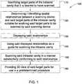
- Fig. 1illustrates a block diagram of the 3D data acquisition process 100 according to an embodiment of the invention
- Fig. 2illustrates the main elements of a system 200 for carrying out the method according to an embodiment of the invention.
- the system 200typically comprises a microprocessor or any other suitable computer, having an input interface or module 210 such as a keyboard, mouse, tablet, and so on, an output device or display means or module 220, typically a screen or monitor but may additionally or alternatively include a printer, or any other display system, a processing unit or module 230 such as for example a CPU, and a memory 240.
- a suitable scanner 250 for obtaining 3D data of the intraoral cavityis also operatively connected to the system 200 and interacts therewith, while in other embodiments the scanner 250 may provide the 3D data to another system not necessarily connected in any way with system 200.
- a probe for determining three dimensional structure by confocal focusing of an array of light beamsmay be used, for example as manufactured under the name of CB-CAD or as disclosed in WO 00/08415 , the contents of which are incorporated herein in their entirety.
- scanning of the dental cavity to provide the 3D datamay be accomplished using any suitable apparatus typically comprising a hand held probe.
- the target parts of the intraoral cavityare identified.
- the target partsare the parts (also referred to herein as zones or areas) of the intraoral cavity which form the focus of a particular dental procedure for a particular patient and regarding which it is desired to obtain the 3D topographical or surface data thereof.
- the target partstypically include the part of the tooth or the teeth, or other dental material on which the particular procedure is to be performed, and in some cases may include the full mandibular or maxillary arches, or both arches.
- the proceduremay be a prosthodontic procedure involving a crown prosthesis to be designed and fabricated for fitting onto a preparation at a particular dental site.
- the dental practitionerinputs into processing unit 230 the tooth which has been targeted for the procedure, identified according to any suitable convention.
- the display 220may be used to display a standard image or graphical representation 211 of a nominal intraoral cavity, either with three-dimensional (3D) attributes or a simple two dimensional (2D) representation.
- a non graphical (for example alphanumeric) representation of the intraoral cavitymay be provided.
- the representation 211includes a plurality of icons or images or symbols 212, one each corresponding to the teeth in a normal adult or child (the age of the patient having first been input to the processing unit 230 ).
- the tooth which is to be the target of the proceduremay be identified by "clicking" with the aid of a mouse, for example, on the appropriate symbol 212.
- any other interactive methodmay be used for choosing the target tooth, for example by means of a touch screen arrangement.
- the identity of the target toothmay be manually input to the processing unit 230 using any conventional nomenclature, a unique coding convention, by selection on a drop-down menu or the like, or in any other suitable manner, the processing unit 230 having been suitably programmed to recognise the choice made by the user.
- the two or more teeth that are to be worked on to provide preparations to receive the bridgeare identified, for example in a similar to that described above, mutatis mutandis.
- the teeth in one or both jawsare required.
- all of the teeth of the upper jaw, lower jaw or both jawsmay be chosen by means on a single appropriate symbol, for example as indicated at 213, 214, 215, respectively, in Fig. 3 .
- the manner in which the intraoral cavity needs to be scannedmay depend on the procedure to be applied thereto, as will become clearer as the description proceeds.
- the dental practitioneralso inputs to the processing unit 230 the identity of the actual procedure.
- the dental practitionermay choose the procedure from a number of preset options on a drop-down menu or the like, from icons or via any other suitable graphical input interface.
- the identity of the proceduremay be input in any other suitable way, for example by means of preset code, notation or any other suitable manner, the processing unit 230 having been suitably programmed to recognise the choice made by the user.
- the proceduresmay be broadly divided into prosthodontic and orthodontic procedures, and then further subdivided into specific forms of these procedures, as known in the art.
- the type of scanner 250 to be usedis also input to the processing unit, typically by choosing one among a plurality of options. If the scanner that is being used is not recognisable by the processing unit 230, it may nevertheless be possible to input operating parameters of the scanner thereto instead. For example, the optimal spacing between the scanner head and the tooth surface can be provided, as well as the capture area (and shape thereof) of the dental surface capable of being scanned at this distance. Alternatively, other suitable scanning parameters may be provided. In any case, it may be desired that the virtual model of the dentition, provided using the scanners, may be dimensionally related to the real dentition in a known manner, so that dimensional measurements of the virtual model may be made.
- the processing unit 230identifies the required spatial relationships that are required for scanning the appropriate parts of the intraoral cavity so that complete and accurate 3D data may be obtained for the procedure in question.
- This steputilises the data already provided in step 110 for establishing the optimal manner for scanning the intraoral cavity, and thus will depend on the nature of the aforesaid data.
- additional or ancillary parts of the intraoral cavity that need to be scanned for the particular procedureare also identified, and the spatial relationship between the scanner and these parts are identified or determined.
- a scanning protocolis identified or determined by relating the type of scanner, resolution thereof, capture area at an optimal spacing between the scanner head and the dental surface to the target parts and the ancillary parts, either separately or together.
- the scanning protocoltypically comprises a series of scanning stations spatially associated with the dental surfaces of the target part and the ancillary part.
- significant overlapping of the images or scans capable of being obtained at adjacent scanning stationsis designed into the scanning protocol to enable good registration, and the 3D data obtained at each scanning station is stitched together to provide a composite 3D virtual model, as is known in the art.
- Fig. 4illustrates an idealised portion 300 of the intraoral cavity of a patient requiring a crown prosthesis on a preparation P having teeth A , B, adjacent thereto, and teeth A', P' and B' in opposed relationship thereto from the other jaw.
- This idealised portion 300is typically a 3D virtual model of an idealised full dentition of an adult that is stored in the memory 240 of the system 200.
- idealisedis simply meant that the idealised dentition comprises 3D models of all of the teeth of an adult in their normal relative positions, the 3D models typically being standardised according to the statistical norm regarding size, shape and so on as commonly found in the population.
- any 3D virtual modelmay be suitable, so long as it includes the 3D virtual models of the teeth corresponding to the teeth of the patient in the required target part and ancillary part.
- the memory 240may also comprise idealised virtual models of the teeth of children or of special population groups, and thus the user typically specifies (and may optionally be prompted to do so by the system 200 ) the age of the patient, or other attribute that best decides the closest idealised virtual model with respect thereto.
- the memory 240also comprises, for each virtual tooth model of the 3D virtual model 300, an idealised virtual preparation model, and according to the prosthodontics procedure required by the patient, one or more of the virtual teeth may be replaced with the corresponding one or more virtual preparations.
- the target area or part to be scannedis represented by the dotted line T, and includes the preparation P, including the finish line LT, and part of the original tooth above the gumline.
- the preparation Pincluding the finish line LT, and part of the original tooth above the gumline.
- Ancillary parts of the intraoral cavityare included in dotted line AT, and comprise parts of the adjacent and opposed teeth, principally teeth A, B, P', and often to a lesser extent teeth A' and B' or parts thereof.
- the resolution of the scanned data for the ancillary parts ATmay be less than for the target part T, since the manufacturing accuracy for the external surfaces of the crown prosthesis (the design of which is dependent on the dental surfaces of the ancillary parts) may be substantially less than for the internal surface of the coping or prosthesis.
- the scanning protocolmay be designed as follows.
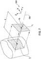
- each scanning station S i(also referred to herein as an image capture station), 3D data within an area I i ' of the dental surface X of a tooth or preparation, for example, may be captured by the scanner 250, and this area may be represented at the scanning station S i by a projection I i of area I i ' on a plane orthogonal to the scanning axis OA of the scanner, and displaced from the dental surface by a dimension t.
- This dimension tis typically the optimal spacing of the particular scanner with respect to the dental surface X for providing a scan area equivalent to I i , but may be any other suitable spacing.
- the shape of the area I iwill generally depend on the scanner, and is herein represented by a rectangle.
- the orientation of the scanning axis OAcan be related to a reference coordinate system, for example orthogonal Cartesian axes 320 defined with respect to the model 300, and which are typically easily identified in the real intraoral cavity.
- areas I 1 , I 2 , I 3 and areas I 4 , I 5 , I 6represent two sets of three overlapping zones each at approximately two different heights with respect to the gum G which may be sufficient to define a buccal portion of the target part T and the ancillary part AT of the lower jaw of Fig.
- areas I 4 , I 5 , I 6are represented by U-shaped symbols, wherein the arms of the U represent the direction along which the scan is taken, i.e., the spatial position of the scanning axis OA of the scanner, and the middle portion of the U represents the corresponding projection I i as seen edge-on.
- exemplary additional areas I 10 and I 11represent additional scanning stations not coplanar with the scans at areas I 4 , I 5 , I 6 .
- the areas I 7 , I 8 , I 9 , I 12 , I 13 , I 14in Figs.
- 5 and 6represent additional scanning areas taken from above the tooth, with greater overlap between areas being provided in the vicinity of the target part T.
- areas I 13 , I 14being more face-on with respect to parts of the finish line may provide greater accuracy thereof.
- the location and orientation of scanning stations S iare determined such that the areas I i ' of the idealised model corresponding to these stations adequately cover the corresponding target parts T and ancillary parts AT thereof.
- the required 3D data of the target part T and ancillary part ATmay be obtained, as will be described in greater detail hereinbelow.
- the scanning protocol for the dental surfaces of the opposed jaw that are included in the target part T and the ancillary part ATmay be obtained in a similar manner to that described above for the lower jaw, mutatis mutandis.
- the scanning protocolwill differ when different scanners are used for the same target area, depending on the capture characteristics of the scanner used.
- a scanner capable of scanning a larger dental area with each scane.g., having a larger filed of view
- the number and disposition of scanning stations for a scanner having a rectangular scanning grid(and thus providing projected scanning areas I i in the form of corresponding rectangles) will typically be different from those for a scanner having a circular or triangular scanning grid (which would provide projected scanning areas I i in the form of corresponding circles or triangles, respectively).
- ancillary parts to be scannedinclude at least part of the teeth adjacent to the furthermost distal preparation and adjacent the furthermost mesial preparation, and at least a portion of the teeth facing the preparations from the opposed jaw.
- the target partmay comprise the full dentition of one or both jaws, respectively.
- the system 200may calculate each time a new idealised scanning protocol based on the parameters of the scanner, the procedure, the dental site of the procedure, age of the patent, and so on, and as applied to the idealised virtual model 300.
- all the necessary scanning protocolsare previously calculated for every type of scanner, procedure, age group and so on, and stored in memory 240, the most suitable protocol being retrieved therefrom when identified according to the particular patient/procedure/scanner parameters that are provided.
- the virtual model 300may not be needed for the purpose of determining customised scanning protocols.
- the memory 240comprises a standard scanning protocol for each different type of procedure, and this protocol is modified by the processing unit 230 to take account of at least one of the parameters including: age of dental patient, dental target part, scanner characteristics, and so on.
- step 130the spatial relationship between the scanning stations S i and the intraoral cavity are displayed, so that in step 140 these displayed relationships may be used as a guide by the dental practitioner for scanning the intraoral cavity in a manner suitable for obtaining 3D data appropriate for the particular procedure being considered.
- step 140There are many ways of displaying the aforesaid spatial relationships, some examples of which will now be described.
- a pair of perspective view images K imay be displayed, on a screen 220 or as printed material, for example, corresponding to the spatial relationship of the scanner 250 with respect to the idealised intraoral cavity 300 at a particular scanning station S i .
- a plurality of images showing the relationship at any other desired vantage pointmay be provided, including for example the vantage point as would be seen by a dental practitioner with respect to a real intraoral cavity, either by default or by being chosen by the user by interacting with processing unit 230.
- a dynamic imagemay be provided, in which the user can change the vantage point of the image interactively, in a manner known in the art.
- a video clip or the likemay be provided for providing the user with a sequence of operations of the scanner etc.
- Images K imay be composites of virtual models of the scanner 250 and of the intraoral cavity 300 (typically the aforesaid idealised virtual model) stored in memory 240. These virtual models are manipulated by the processing unit 230 to provide the correct spatial relationship, in virtual space, according to the particular scanning station S i previously determined, and can be displayed as two dimensional images in a manner known in the art.
- the position of the scanning station S i and the direction of the scanning axis OAcan be displayed with respect to the intraoral cavity 300, additionally or alternatively to the scanner.
- the scanning axis OAis typically defined as orthogonal to the scanning face 255 of the scanner, but may be defined according to any other preknown suitable geometric or other parameter of the scanner.
- the images K ican optionally comprise a representation of the coordinate system, for example orthogonal axes 320, in the orientation appropriate to the vantage point being viewed.
- each dental surfacemay be represented, for example, by a geometrical form - for example simple wedges representing incisors, cones representing canines, and cylinders representing molars.
- a summary composite imagemay be first provided (not shown) illustrating the full protocol, for example as a plurality of symbols (e.g. indicia such as "X" or "+”, or frames representing the projected areas I i , and so on) may be superposed over one or more images of the idealised dentition - for example, in a manner similar to that illustrated in Figs. 5 and 6 .
- symbolse.g. indicia such as "X" or "+”, or frames representing the projected areas I i , and so on
- the idealised virtual model appearing in images K imay be custom-modified to show a virtual preparation at each corresponding dental site where a real preparation is to be found, and also virtual teeth may be removed from the model where none are to be found in the real intraoral cavity - for example where teeth have been removed for accommodating a pontic.
- non-image datamay be provided identifying the position and orientation of the scanner at each scanning station S i , and this data may be provided, for example, in the form of a table listing suitable corresponding geometric data, and also including, for example the spacing between the scanner scanning face 255 and the dental surface of interest, an identification of the particular surface being scanned, and so on.
- the relationships in step 130may be displayed in alphanumeric form, as a set of instructions or statements describing the relative positions of the scanner and teeth, for example.
- the relationships in step 130may be displayed in audible form, wherein for example such instructions or statements are broadcast by a speaker or the like, either from a prerecording, or synthetically created by the system 200.
- the scanning stations S imay be successively displayed in any desired order, for example in an order such as to minimise displacement of the scanner between each successive scan.
- step 130is followed by the step 140 of using the displayed relationships as a scanning guide, and step 150 of scanning the intraoral cavity in a manner substantially conforming to said relationships.
- the images corresponding to a next scanning stationare, optionally, not displayed until the practitioner is confident that he/she has properly scanned the intraoral cavity as required by the current scanning station. This may be accomplished by operatively connecting the scanner 250 to the processing unit 230, and prompting the user whether to display the next scanning station every time a scan is taken (and which is detected by the unit 230 ).
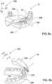
- FIGs. 9a and 9bA second embodiment of step 130 is illustrated in Figs. 9a and 9b , and in this embodiment, use is made of the video image capturing capabilities of the scanner 250, which is configured with such capabilities, for guiding the same.
- a suitable symbolsuch as cross-hairs 400, occlusal line 410, and so on may be superimposed on the viewfinder of the scanner 250, typically displayed on the screen 220 (or printed for example).
- the spatial relationships of step 120are displayed from the vantage point of the scanner 250, and takes the form of providing a reference marker, such as the aforesaid cross-hairs 400, for example, on the screen where a particular part of the dental surface (e.g., the centre of a tooth viewed in he particular direction of he scanning axis) being viewed should be centred.
- a reference markersuch as the aforesaid cross-hairs 400
- the appropriate scan for the scanning stationmay be taken when the upper tooth 405 and the lower tooth 406 (previously identified by the system as being the subject of the scan) as imaged from a buccal direction by the scanner are each centralised with respect to the upper and lower cross-hairs 400.
- Fig. 9athe appropriate scan for the scanning station may be taken when the upper tooth 405 and the lower tooth 406 (previously identified by the system as being the subject of the scan) as imaged from a buccal direction by the scanner are each centralised with respect to the upper and lower cross-hair
- the tooth 407 being imaged from aboveis centralised with respect to cross-hairs 400.
- the cross-hairs 400may further comprise a ring 401 which further facilitates centering the tooth 407 as viewed via the scanner 250 with respect to the cross-hairs 400.
- Proceeding to and identifying the next scanning stationis facilitated by displacing the cross-hairs 400 to a position on the screen where the last position of the cross-hairs 400 appears in the next (now current) position of the scanning station.
- Thisis accomplished automatically by the processing unit 230 when the user is satisfied that the previous scan was properly taken, for example as described earlier in connection with the embodiment of Figs. 8a, 8b , mutatis mutandis.
- the scanneris then moved so that the cross-hairs 400 (still associated in virtual space with the previous scanning station, and now appearing at the relocated position on the viewfinder) is again centralised with the previous dental surface, which has been effectively displaced from the central position of the screen to a position once again associated with the now-displaced cross-hairs 400.
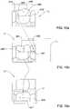
- Fig. 10aillustrates an image L in buccal view of a series of teeth, with the cross-hairs 400 centralised over one particular tooth 410, the adjacent teeth 411 and 412 being partially visible.
- a suitable scanwas taken at this scanning station, this is made known to the system 200 in any suitable manner, and the cross-hairs 400 is moved from the previous position at the centre of the screen to the right, such that only the left hand portion 401 of the cross-hairs 400 is now visible.
- the userthen moves the scanner such as to renew the relative position of tooth 410 with respect to cross-hairs 400 in the viewfinder, to for example as illustrated in the image of Fig.
- the new position of the cross-hairs 400is relocated, for example to the lower pat of the viewfinder, and the user correspondingly translates the scanner so as to re-locate tooth 411 to maintain the previous relative position with respect to the cross-hairs 400, providing image L", and the position of the previous image L' is shown in the dotted box in this figure.
- This processis repeated until all the scanning stations have been passed. It may be necessary to change to direction of the scanning entirely, for example from buccal ( Fig. 9a ) to upper ( Fig.
- optical recognitionalso known as image recognition
- image Mis a video image corresponding to the latest scan, obtained at the current scanning station.
- Image Mshows the relative positions of various dental surfaces such as a tooth 430 in lingual view, flanked by adjacent teeth 431, 432.
- Suitable optical or image recognition meansare applied to image M, which is first isolated in processing unit 230 by means of a suitable frame grabber, and a profile of interest, MP, is determined.
- Such a profile MPtypically comprises an external edge of one or more of teeth 430, 431, 432 as seen from the vantage point of scanner 250, and thus typically comprises a fictitious line separating two zones that are optically different - the teeth and the background, for example.
- the profile MPis then reproduced as an image in the viewfinder in its original relative position in image M.
- the processing unit 230calculates the movement of the scanner required to move to the next scanning station, and applies this movement, in a virtual manner to the profile MP, repositioning the profile MP to position MP', or at last a part thereof, in the viewfinder, as illustrated in Fig. 11b .
- Fig. 11bshows image M' obtained prior to full alignment - the scanner 250 having to be moved in the direction of arrow 450 until the profile MP' is superposed on part of the edges MP" of the teeth as seen via the viewfinder.
- the guidingmay take any suitable form.
- oral commandsmay be provided, asking the practitioner to now move the scanner to the left 3mm and upwards 2mm, for example, using any suitable speech software operating on scanning station data inputs provided by the processing unit 230.
- non-oral audio commandsmay be provided, for example coded bells or beeps, the pattern and intensity thereof being capable of being interpreted by the user in terms of the required movement in a number of directions, for example.
- non-graphical meansmay be used for guiding the user between scanning stations.
- suitable LED'smay be provided in the viewfinder, or images of arrows, for example, for guiding the user in the required directions to the next scanning station.
- the scanner 250comprises an inertial system or a suitable tracking system, that is capable of determining a change of position and/or orientation thereof relative to a datum position/orientation.
- the actual position/orientation of the scanner 250can be checked automatically against the desired position for the next scan, and any suitable means - audio and/or visual for example - may be used for guiding the user to the correct position based on the difference between the current position and the desired position.
- any suitable means - audio and/or visual for example -may be used for guiding the user to the correct position based on the difference between the current position and the desired position.
- a beepmay be sounded the frequency of which increases the closer the scanner 250 is to the desired position.
- a second inertial or tracking systemmay be coupled to the head or jaws of the patient, so that any movement thereof may be compensated for.
- a series of indiciamay be provided, each indicia in the series corresponding to a different scanning station.
- the series of indiciamay be displayed in a predetermined sequence, a next indicia being displayed after the intraoral cavity has been scanned at the previous scanning station with its corresponding indicia.
- the next indiciamay be displayed together with the current, i.e., the immediately preceding indicia.
- the indicia relating to different said parametersare displayed in different colors one from another. Thus, these indicia help to identify which scanning station the user is at, and which is the next station, for example.
- the indicia_may comprise a series of numbers (for example "1/4", "2/4", "3/4", "4/4" ) or symbols, for example.
- a computer readable mediumthat embodies in a tangible manner a program executable for guiding the scanning of the intraoral cavity of a patient.
- the computer readable mediumcomprises:
- the mediummay comprise, for example, optical discs, magnetic discs, magnetic tapes, and so on.
- a method and systemare provided for scanning, and for facilitating scanning of, an intraoral cavity.
- the target parts of the intraoral cavity that it is desired to have scannedare identified, and the spatial relationships between a scanning device and the target parts of the intraoral cavity suitable for enabling said target parts to be scanned by said scanning device, are also identified or otherwise determined. These relationships are then displayed, and the displayed relationships are used as a guide for scanning the intraoral cavity.
Landscapes
- Health & Medical Sciences (AREA)
- Life Sciences & Earth Sciences (AREA)
- Public Health (AREA)
- General Health & Medical Sciences (AREA)
- Veterinary Medicine (AREA)
- Animal Behavior & Ethology (AREA)
- Dentistry (AREA)
- Oral & Maxillofacial Surgery (AREA)
- Epidemiology (AREA)
- Physics & Mathematics (AREA)
- Engineering & Computer Science (AREA)
- Medical Informatics (AREA)
- Pathology (AREA)
- Biomedical Technology (AREA)
- Molecular Biology (AREA)
- Surgery (AREA)
- Heart & Thoracic Surgery (AREA)
- Biophysics (AREA)
- Optics & Photonics (AREA)
- Physical Education & Sports Medicine (AREA)
- Rheumatology (AREA)
- Orthopedic Medicine & Surgery (AREA)
- General Physics & Mathematics (AREA)
- Primary Health Care (AREA)
- Databases & Information Systems (AREA)
- Data Mining & Analysis (AREA)
- General Engineering & Computer Science (AREA)
- Nuclear Medicine, Radiotherapy & Molecular Imaging (AREA)
- Radiology & Medical Imaging (AREA)
- Dental Tools And Instruments Or Auxiliary Dental Instruments (AREA)
- Length Measuring Devices By Optical Means (AREA)
- Endoscopes (AREA)
Description
- This invention relates to a system and method for providing guidance for scanning the intra oral cavity to provide three dimensional data that may be subsequently used in prosthodontic and orthodontic procedures in the intra oral cavity. In particular, the invention relates to such systems and methods that are computerized.
- In prosthodontic procedures designed to implant a dental prosthesis in the intra oral cavity, the dental site at which the prosthesis is to be implanted in many cases needs to be measured accurately and studied carefully, so that a prosthesis such as a crown or bridge, for example, can be properly designed and dimensioned to fit in place. A good fit is of the highest importance to enable mechanical stresses to be properly transmitted between the prosthesis and the jaw, and to prevent infection of the gums and so on via the interface between the prosthesis and the dental site, for example.
- In the prior art, the dental site is prepared by the dental practitioner, and a positive physical model of the site is constructed using known methods. Alternatively, the dental site may be scanned to provide 3D data of the site. In either case, the virtual or real model of the site is sent to the dental lab, which manufactures the prosthesis based on the model. However, if the model is deficient or undefined in certain areas, or if the preparation was not optimally configured for receiving the prosthesis, the dental technician has a more difficult job ahead than otherwise, and the design of the prosthesis may be less than optimal. For example, if the insertion path implied by the preparation for a closely-fitting coping would result in the prosthesis colliding with adjacent teeth, the coping geometry has to be altered to avoid the collision, but this may result in the coping design being less optimal. Further, if the area of the preparation containing the finish line lacks definition, it may not be possible to properly determine the finish line and thus the lower edge of the coping may not be properly designed. Indeed, in some circumstances, the model is rejected and the dental practitioner must re-scan the dental site, or must rework the preparation, so that a suitable prosthesis may be produced.
- In orthodontic procedures it is also necessary to provide a model of one or both jaws. Where such orthodontic procedures are designed virtually (herein also referred to as "numerically"), a virtual model of the intraoral cavity is also required, and this may be obtained, inter alia, by scanning the intraoral cavity directly, or by producing a physical model of the dentition, and then scanning the model with a suitable scanner.
- Thus, in both prosthodontic and orthodontic procedures, obtaining a three-dimensional (3D) model of a least a part of the intraoral cavity is an initial requirement. When the 3D model is a virtual model, the more complete and accurate the scans of the intraoral cavity are, the higher the quality of the virtual model, and thus the greater the ability to design an optimal prosthesis or orthodontic treatment.
- Prior art methods of scanning the intraoral cavity do not provide guidance to the dental practitioner on how to ensure full and accurate scanning of parts of the cavity of interest for a particular orthodontic or prosthodontic procedure. Rather, the dental practitioner uses his or her judgment on site, and it is often the case that the scans of some areas of interest may be defective, while other unimportant areas may be scanned to great accuracy with details, which is wasteful of the practitioner's and the patient's time.
- From
WO 99/16380 US 4,575,805 A1 andUS 2005/0186540 A1 .US 4,575,805 A1 discloses a method and apparatus for the fabrication of custom-shaped implants. The surface characteristics of an organ that needs restoration, for example, a tooth which has been prepared for an inlay insertion, are read by means of a noncontact scan-head. The three-dimensional shape parameters of the implant required to restore the tooth in function and appearance are computed on the basis of the recorded contour data. These parameters are then used in a program sequence which controls a milling, cutting or erosive process in order to manufacture the restorative inlay while the patient waits. - Herein, "dental material" refers to any material associated with dental structures of the intra oral cavity, including but not limited to natural dental materials such as for example enamel, dentine, pulp, dental roots, and non-natural dental materials such as for example metallic and non-metallic filings, restorations, crowns, bridges, copings, preparations, and so on.
- Herein, "dental clinic" refers to the interface between a dental practitioner and a patent, and thus includes any physical entity, in particular a clinic, in which there is interaction between a dental patient and a dental practitioner. While "dental practitioner" typically refers to a dentist, doctor or dental technician, it also includes herein all other caregivers that may interact with a dental patient during the course of a dental treatment. While "dental patient" typically refers to a person requiring the dental services of a dental practitioner, it also includes herein any person regarding whom it is desired to create a 3D numerical model of the intra oral cavity thereof, for example for the purpose of practicing the same or for carrying out research.
- The term "prosthesis" is herein taken to include any restoration and any onlays, such as crowns and bridges, for example, and inlays, such as caps, for example, and any other artificial partial or complete denture.
- While the term "preparation" typically refers to the stump (including the finish line and optionally the shoulder) that is left of the tooth that is to be replaced by the prosthesis - typically a crown - and on which the crown is to be mounted, the term herein also includes artificial stumps, pivots, cores and posts, or other devices that may be implanted in the intraoral cavity in such a position or in a position that is optimal for implanting the crown.
- The term "prosthodontic procedure" refers, inter alia, to any procedure involving the intraoral cavity and directed to the design, manufacture or installation of a dental prosthesis at a dental site within the intraoral cavity, or a real or virtual model thereof, or directed to the design and preparation of the dental site to receive such a prosthesis.
- The term "orthodontic procedure" refers, inter alia, to any procedure involving the intraoral cavity and directed to the design, manufacture or installation of orthodontic elements at a dental site within the intraoral cavity, or a real or virtual model thereof, or directed to the design and preparation of the dental site to receive such orthodontic elements.
- The term "numerical entity" is used herein synonymously with virtual model, 3D model, and other such terms, and relates to a virtual representation in a computer environment of a real object, typically a dentition or at least a part of intraoral cavity, or of a real model thereof, for example.
- The term "scanning" and its analogues refer to any procedure directed at obtaining 3D topographic data of a surface, particularly of a dental surface, and thus includes mechanical methods, typically based on 3D probes for example, optical methods, including for example confocal methods, for example as disclosed in
WO 00/08415 - The present invention is directed to a method for scanning an intraoral cavity, and thus to a corresponding method for facilitating scanning of an intraoral cavity, the method comprising
- (a) identifying target parts of the intraoral cavity that it is desired to have scanned;
- (b) identifying spatial relationships between a scanning device and said target parts of the intraoral cavity suitable for enabling said target parts to be scanned by said scanning device;
- (c) displaying said relationships; and
- (d) using said displayed relationships as a guide for scanning the intraoral cavity, whereas step (b) comprises, for each said target part, determining for said scanning device a series of spatial parameters, each comprising a scanning station data sufficient for enabling said scanning device to fully scan said corresponding target part.
- The method further comprises the step of scanning said intraoral cavity in a manner substantially conforming to said relationships.
- The scanning substantially provides 3D data of said target parts for use in a predetermined procedure. Step (a) may include identifying ancillary parts in said intraoral cavity associated with said target parts, wherein 3D data of said ancillary parts is also required for use in said predetermined dental procedure. Step (b) may comprise, for each said target part and each said ancillary part, determining for said scanning device a series of spatial parameters, each comprising a scanning station data sufficient for enabling said scanner to fully scan said corresponding ancillary part. Optionally, the scanning station data of said series include a proximity and a relative orientation of said scanner with respect to said target part or ancillary part such as to enable said scanner to obtain 3D topographical data of an area of said target part or ancillary part. The series provide 3D topographical data for a corresponding plurality of said areas, wherein said spatial parameters of said series are determined such at least some adjacent said areas overlap one another.
- In one embodiment, step (c) comprises displaying a nominal image comprising an image of at least a portion of an nominal intraoral cavity, comprising corresponding said target parts and said ancillary parts, and an image of a nominal scanner in a spatial relationship with respect to one another corresponding to the spatial relationship as determined in step (b) for at least one parameter of said series of parameters. A series of said nominal images may be provided, each image in said series corresponding to a different one of said parameters of said series of parameters. The series of images can be displayed in any predetermined sequence. Optionally, the nominal image comprises 3D attributes. The image may comprise said nominal intraoral cavity at any desired orientation with respect to a predetermined coordinate system. The coordinate system may comprise, for example, an orthogonal Cartesian axes system. The orientation may optionally correspond to a real life view of the intraoral cavity of a patient from the vantage point of a dental practitioner. Optionally, an audio and/or visual cue is provided for prompting the user to proceed to the next image.
- In another embodiment, step (c) comprises displaying indicia on a viewfinder capable of providing a video image of the field of view of said scanner, said indicia being indicative of a desired position for associating a predetermined portion of said target parts or ancillary parts in a particular manner with respect therewith. The indicia may comprise, for example, an "+" or an "X" or any other suitable symbol, which may be, for example, geometrical, alphanumeric and so on.
- In a variation of this embodiment, the indicia comprise a symbol representative of a profile corresponding to an expected view of said target part or ancillary part in said viewfinder. Optical or image recognition methods can be applied to said video image for providing a profile of the image, said symbol comprising said profile. For example, the profile comprises a shaped line shaped as an outline of a tooth as seen via said viewfinder. The symbol may comprise a shaped line shaped as an outline of a tooth seen in any one of top view, buccal view or lingual view, for example.
- Optionally, a series of indicia are provided, each indicia in said series corresponding to a different one of said parameters of said series of parameters. said series of indicia may be displayed in a predetermined sequence, a next indicia being displayed after the intraoral cavity has been scanned according to the previous said parameter and corresponding indicia. Said next indicia may be displayed together with the immediately preceding indicia. Optionally, indicia relating to different said parameters may be displayed in different colors one from another.
- The aforesaid procedure may be, for example, a prosthodontic procedure for a crown with respect to a preparation, said target parts comprising said preparation, and said ancillary parts comprising at least a portion of the teeth adjacent to said preparation and facing said preparation from the opposed jaw.
- The aforesaid procedure may be, for example, a procedure is a prosthodontic procedure for a bridge with respect to a plurality of preparations, said target parts comprising said preparations, and said ancillary parts comprising at least a portion of the teeth adjacent to a furthermost distal preparation and adjacent a furthermost mesial preparation, and at least a portion of the teeth facing said preparations from the opposed jaw.
- The aforesaid procedure may be, for example, a procedure is an orthodontic procedure, and said target parts comprise the full dentition of at least one jaw of said intraoral cavity.
- Typically the method of the invention is a computerized method, i.e., executed partly or fully with the aid of a processing unit such as a computer. Nevertheless, at least some embodiments may be executed without the need of a computer.
- The present invention also relates to a computer readable medium that embodies in a tangible manner a program executable for guiding the scanning of the intraoral cavity of a patient, comprising:
- (a) a first set of data representative of target parts of the intraoral cavity that it is desired to have scanned;
- (b) a second set of data representative of spatial relationships between a scanning device and said target parts of the intraoral cavity suitable for enabling said target parts to be scanned by said scanning device.
- The computer readable medium may further comprise means such as manipulation routines, computer instructions, and so on, for example, for manipulating said second set of data for enabling displaying said second data.
- The medium may comprise any one of optical discs, magnetic discs, magnetic tapes, and so on, for example.
- The present invention is also directed to a system for guiding the scanning of an intraoral cavity, comprising:
- (A) input module for identifying target parts of the intraoral cavity that it is desired to have scanned;
- (B) processing module for generating spatial relationships between a scanning device and said target parts of the intraoral cavity suitable for enabling said target parts to be scanned by said scanning device;
- (C) display module for displaying said relationships.
- The system preferably also comprises a suitable scanner for scanning according to said relationships
- In order to understand the invention and to see how it may be carried out in practice, a number of embodiments will now be described, by way of non-limiting example only, with reference to the accompanying drawings, in which:
Fig. 1 shows a block diagram of a scanning process according to an embodiment of the invention.Fig. 2 shows a block diagram of a scanning system according to an embodiment of the invention.Fig. 3 shows a virtual representation of a dentition enabling target areas to be chosen interactively.Fig. 4 illustrates target parts and ancillary parts of an intraoral cavity associated with a crown prosthodontic procedure.Fig. 5 shows a buccal view of an idealised virtual model of a nominal intraoral cavity showing a plurality of scanning stations.Fig. 6 shows a top view of an idealised virtual model of a nominal intraoral cavity showing a plurality of scanning stations.Fig. 7 shows the relationship between an scanning station and a dental surface being scanned thereat.Figs 8a and8b illustrate examples of display output using the system ofFig. 2 according to one embodiment.Figs 9a and9b illustrate examples of display output using the system ofFig. 2 according to another embodiment.Figs 10a, 10b, 10c illustrate the embodiment ofFigs 9a, 9b , used for guiding scanning from one scanning station to a next scanning station.Figs 11a and11b illustrate examples of display output according to a variation of the embodiment ofFigs. 9a, 9b .Fig.1 illustrates a block diagram of the3Ddata acquisition process 100 according to an embodiment of the invention, andFig.2 illustrates the main elements of asystem 200 for carrying out the method according to an embodiment of the invention. Thesystem 200 typically comprises a microprocessor or any other suitable computer, having an input interface ormodule 210 such as a keyboard, mouse, tablet, and so on, an output device or display means ormodule 220, typically a screen or monitor but may additionally or alternatively include a printer, or any other display system, a processing unit ormodule 230 such as for example a CPU, and amemory 240. In some embodiments, asuitable scanner 250 for obtaining3D data of the intraoral cavity is also operatively connected to thesystem 200 and interacts therewith, while in other embodiments thescanner 250 may provide the3D data to another system not necessarily connected in any way withsystem 200. Advantageously, a probe for determining three dimensional structure by confocal focusing of an array of light beams may be used, for example as manufactured under the name of CB-CAD or as disclosed inWO 00/08415 - At
step 110, the target parts of the intraoral cavity are identified. The target parts are the parts (also referred to herein as zones or areas) of the intraoral cavity which form the focus of a particular dental procedure for a particular patient and regarding which it is desired to obtain the3D topographical or surface data thereof. The target parts typically include the part of the tooth or the teeth, or other dental material on which the particular procedure is to be performed, and in some cases may include the full mandibular or maxillary arches, or both arches. For example, the procedure may be a prosthodontic procedure involving a crown prosthesis to be designed and fabricated for fitting onto a preparation at a particular dental site. In such a case, the dental practitioner inputs intoprocessing unit 230 the tooth which has been targeted for the procedure, identified according to any suitable convention. For example, and referring toFig.3 , thedisplay 220 may be used to display a standard image orgraphical representation 211 of a nominal intraoral cavity, either with three-dimensional(3D) attributes or a simple two dimensional(2D) representation. Alternatively, though, a non graphical (for example alphanumeric) representation of the intraoral cavity may be provided. Thus, and referring to the example illustrated inFig. 3 , therepresentation 211 includes a plurality of icons or images orsymbols 212, one each corresponding to the teeth in a normal adult or child (the age of the patient having first been input to the processing unit230). The tooth which is to be the target of the procedure may be identified by "clicking" with the aid of a mouse, for example, on theappropriate symbol 212. Alternatively, any other interactive method may be used for choosing the target tooth, for example by means of a touch screen arrangement. In another example, the identity of the target tooth may be manually input to theprocessing unit 230 using any conventional nomenclature, a unique coding convention, by selection on a drop-down menu or the like, or in any other suitable manner, theprocessing unit 230 having been suitably programmed to recognise the choice made by the user. - Alternatively, for a prosthodontics procedure involving a bridge, the two or more teeth that are to be worked on to provide preparations to receive the bridge are identified, for example in a similar to that described above,mutatis mutandis. For orthodontic procedures typically all of the teeth in one or both jaws are required. In such a case, all of the teeth of the upper jaw, lower jaw or both jaws may be chosen by means on a single appropriate symbol, for example as indicated at213, 214, 215, respectively, in
Fig.3 . - The manner in which the intraoral cavity needs to be scanned may depend on the procedure to be applied thereto, as will become clearer as the description proceeds. Thus, the dental practitioner also inputs to the
processing unit 230 the identity of the actual procedure. For this purpose, the dental practitioner may choose the procedure from a number of preset options on a drop-down menu or the like, from icons or via any other suitable graphical input interface. Alternatively, the identity of the procedure may be input in any other suitable way, for example by means of preset code, notation or any other suitable manner, theprocessing unit 230 having been suitably programmed to recognise the choice made by the user. By way of non-limiting example, the procedures may be broadly divided into prosthodontic and orthodontic procedures, and then further subdivided into specific forms of these procedures, as known in the art. - The type of
scanner 250 to be used is also input to the processing unit, typically by choosing one among a plurality of options. If the scanner that is being used is not recognisable by theprocessing unit 230, it may nevertheless be possible to input operating parameters of the scanner thereto instead. For example, the optimal spacing between the scanner head and the tooth surface can be provided, as well as the capture area (and shape thereof) of the dental surface capable of being scanned at this distance. Alternatively, other suitable scanning parameters may be provided. In any case, it may be desired that the virtual model of the dentition, provided using the scanners, may be dimensionally related to the real dentition in a known manner, so that dimensional measurements of the virtual model may be made. - In the
next step 120, theprocessing unit 230 identifies the required spatial relationships that are required for scanning the appropriate parts of the intraoral cavity so that complete and accurate3D data may be obtained for the procedure in question. This step utilises the data already provided instep 110 for establishing the optimal manner for scanning the intraoral cavity, and thus will depend on the nature of the aforesaid data. Further, according to the method of the invention, additional or ancillary parts of the intraoral cavity that need to be scanned for the particular procedure are also identified, and the spatial relationship between the scanner and these parts are identified or determined. Having identified the target parts and ancillary parts, a scanning protocol is identified or determined by relating the type of scanner, resolution thereof, capture area at an optimal spacing between the scanner head and the dental surface to the target parts and the ancillary parts, either separately or together. The scanning protocol typically comprises a series of scanning stations spatially associated with the dental surfaces of the target part and the ancillary part. Preferably, significant overlapping of the images or scans capable of being obtained at adjacent scanning stations is designed into the scanning protocol to enable good registration, and the3D data obtained at each scanning station is stitched together to provide a composite3D virtual model, as is known in the art. A number of examples will now be described. Fig.4 illustrates anidealised portion 300 of the intraoral cavity of a patient requiring a crown prosthesis on a preparationP having teethA,B, adjacent thereto, and teethA', P' andB' in opposed relationship thereto from the other jaw. Thisidealised portion 300 is typically a3D virtual model of an idealised full dentition of an adult that is stored in thememory 240 of thesystem 200. By idealised is simply meant that the idealised dentition comprises3D models of all of the teeth of an adult in their normal relative positions, the3D models typically being standardised according to the statistical norm regarding size, shape and so on as commonly found in the population. Of course, for the purpose of the invention, any3D virtual model may be suitable, so long as it includes the3D virtual models of the teeth corresponding to the teeth of the patient in the required target part and ancillary part. Thememory 240 may also comprise idealised virtual models of the teeth of children or of special population groups, and thus the user typically specifies (and may optionally be prompted to do so by the system200) the age of the patient, or other attribute that best decides the closest idealised virtual model with respect thereto. Thememory 240 also comprises, for each virtual tooth model of the3Dvirtual model 300, an idealised virtual preparation model, and according to the prosthodontics procedure required by the patient, one or more of the virtual teeth may be replaced with the corresponding one or more virtual preparations.- The target area or part to be scanned is represented by the dotted lineT, and includes the preparationP, including the finish lineLT, and part of the original tooth above the gumline. When the target area is scanned very accurately, it is possible for the internal surface of a corresponding coping or prosthesis to be accurately designed. Ancillary parts of the intraoral cavity are included in dotted lineAT, and comprise parts of the adjacent and opposed teeth, principally teethA, B, P', and often to a lesser extent teethA' andB' or parts thereof. Typically, but not necessarily, the resolution of the scanned data for the ancillary partsAT may be less than for the target partT, since the manufacturing accuracy for the external surfaces of the crown prosthesis (the design of which is dependent on the dental surfaces of the ancillary parts) may be substantially less than for the internal surface of the coping or prosthesis. According to the specific nature or properties of the scanner, including the resolution thereof, capture area at an optimal spacing between the scanner head and the dental surface to the target parts and the ancillary parts, the scanning protocol may be designed as follows.
- Referring to
Fig.7 , for example, at each scanning stationSi (also referred to herein as an image capture station),3D data within an areaIi' of the dental surfaceX of a tooth or preparation, for example, may be captured by thescanner 250, and this area may be represented at the scanning stationSi by a projectionIi of areaIi' on a plane orthogonal to the scanning axisOA of the scanner, and displaced from the dental surface by a dimensiont. This dimension t is typically the optimal spacing of the particular scanner with respect to the dental surfaceX for providing a scan area equivalent toIi, but may be any other suitable spacing. The shape of the areaIi will generally depend on the scanner, and is herein represented by a rectangle. The orientation of the scanning axisOA can be related to a reference coordinate system, for example orthogonalCartesian axes 320 defined with respect to themodel 300, and which are typically easily identified in the real intraoral cavity. - Referring to
Figs.5 and6 , theprocessing unit 230 determines a plurality of scanning stationsSi surrounding the target partT and the ancillary partAT (referring also toFig. 4 ) such that the corresponding areasIi', in which3D data is obtained, together cover the full extent of the dental surfaces of interest therein (wherein i = 1,2, 3, ...10, 11, 12, 13, 14..). For example, inFig.5 , areasI1,I2, I3 and areasI4, I5, I6 represent two sets of three overlapping zones each at approximately two different heights with respect to the gumG which may be sufficient to define a buccal portion of the target partT and the ancillary partAT of the lower jaw ofFig.4 . Similar areas may be required form the lingual side. InFig.6 , areasI4, I5, I6 are represented by U-shaped symbols, wherein the arms of the U represent the direction along which the scan is taken, i.e., the spatial position of the scanning axisOA of the scanner, and the middle portion of the U represents the corresponding projectionIi as seen edge-on. Thus, exemplary additional areasI10 andI11 represent additional scanning stations not coplanar with the scans at areasI4, I5, I6. Similarly, the areasI7, I8,I9, I12, I13, I14, inFigs.5 and6 represent additional scanning areas taken from above the tooth, with greater overlap between areas being provided in the vicinity of the target partT. For example, areasI13, I14, being more face-on with respect to parts of the finish line may provide greater accuracy thereof. The location and orientation of scanning stationsSi are determined such that the areasIi' of the idealised model corresponding to these stations adequately cover the corresponding target partsT and ancillary partsAT thereof. Thus, by reproducing these locations and orientations of thescanner 250 with respect to the real intraoral cavity, the required3D data of the target partT and ancillary partAT may be obtained, as will be described in greater detail hereinbelow. - The scanning protocol for the dental surfaces of the opposed jaw that are included in the target partT and the ancillary partAT may be obtained in a similar manner to that described above for the lower jaw,mutatis mutandis.
- Typically, the scanning protocol will differ when different scanners are used for the same target area, depending on the capture characteristics of the scanner used. Thus, a scanner capable of scanning a larger dental area with each scan (e.g., having a larger filed of view) will require less scanning stations to be defined in the scanning protocol than a scanner that is only capable of capturing3D data of a relatively smaller dental surface. Similarly, the number and disposition of scanning stations for a scanner having a rectangular scanning grid (and thus providing projected scanning areasIi in the form of corresponding rectangles) will typically be different from those for a scanner having a circular or triangular scanning grid (which would provide projected scanning areasIi in the form of corresponding circles or triangles, respectively).
- In another example (not illustrated) relating to a prosthodontic procedure for a bridge having a single or a plurality of pontics, there are generally two target parts, relating to one or the other of the two preparations on which the bridge is to be anchored, and the ancillary parts to be scanned include at least part of the teeth adjacent to the furthermost distal preparation and adjacent the furthermost mesial preparation, and at least a portion of the teeth facing the preparations from the opposed jaw.
- In another example (not illustrated) relating to a prosthodontics procedure requiring a restoration on the buccal or lingual part of a particular tooth, only this target part may need to be scanned in the patient together with the occlusal surfaces of the some of the teeth of the opposite jaw as ancillary parts.
- In yet another example (not illustrated) relating to an orthodontic procedure for one or both jaws, the target part may comprise the full dentition of one or both jaws, respectively.
- According to the invention, the
system 200 may calculate each time a new idealised scanning protocol based on the parameters of the scanner, the procedure, the dental site of the procedure, age of the patent, and so on, and as applied to the idealisedvirtual model 300. - Alternatively, all the necessary scanning protocols are previously calculated for every type of scanner, procedure, age group and so on, and stored in
memory 240, the most suitable protocol being retrieved therefrom when identified according to the particular patient/procedure/scanner parameters that are provided. In this case, thevirtual model 300 may not be needed for the purpose of determining customised scanning protocols. Thus, it is possible to provide all the necessary guidance for a particular procedure in printed form, a printed book or pamphlet, for example, by means of a movie or video clip, or in any other communication medium, wherein the user would search for the appropriate guidance images or the like according to the particular parameters of the patient in question, via an index or the like for example, and then open the book/movie and so on at the relevant pages/scene etc., to obtain the guidance required. - Alternatively, the
memory 240 comprises a standard scanning protocol for each different type of procedure, and this protocol is modified by theprocessing unit 230 to take account of at least one of the parameters including: age of dental patient, dental target part, scanner characteristics, and so on. - In
step 130, the spatial relationship between the scanning stationsSi and the intraoral cavity are displayed, so that instep 140 these displayed relationships may be used as a guide by the dental practitioner for scanning the intraoral cavity in a manner suitable for obtaining3D data appropriate for the particular procedure being considered. There are many ways of displaying the aforesaid spatial relationships, some examples of which will now be described. - Referring to
Figs.8a and8b , for example, a pair of perspective view imagesKi may be displayed, on ascreen 220 or as printed material, for example, corresponding to the spatial relationship of thescanner 250 with respect to the idealisedintraoral cavity 300 at a particular scanning stationSi. Additionally or alternatively, a plurality of images showing the relationship at any other desired vantage point (viewpoint) may be provided, including for example the vantage point as would be seen by a dental practitioner with respect to a real intraoral cavity, either by default or by being chosen by the user by interacting withprocessing unit 230. Optionally, a dynamic image may be provided, in which the user can change the vantage point of the image interactively, in a manner known in the art. Alternatively, a video clip or the like may be provided for providing the user with a sequence of operations of the scanner etc. - ImagesKi may be composites of virtual models of the
scanner 250 and of the intraoral cavity300 (typically the aforesaid idealised virtual model) stored inmemory 240. These virtual models are manipulated by theprocessing unit 230 to provide the correct spatial relationship, in virtual space, according to the particular scanning stationSi previously determined, and can be displayed as two dimensional images in a manner known in the art. Optionally, the position of the scanning stationSi and the direction of the scanning axisOA can be displayed with respect to theintraoral cavity 300, additionally or alternatively to the scanner. The scanning axisOA is typically defined as orthogonal to thescanning face 255 of the scanner, but may be defined according to any other preknown suitable geometric or other parameter of the scanner. The imagesKi can optionally comprise a representation of the coordinate system, for exampleorthogonal axes 320, in the orientation appropriate to the vantage point being viewed. - For the purpose of imagesKi, it may be possible to display the image of the dental surfaces as having3D attributes and realistic dental morphologies, for example as illustrated in
Figs. 8a and 8b , or alternatively, each dental surface may be represented, for example, by a geometrical form - for example simple wedges representing incisors, cones representing canines, and cylinders representing molars. - Optionally, a summary composite image may be first provided (not shown) illustrating the full protocol, for example as a plurality of symbols (e.g. indicia such as "X" or "+", or frames representing the projected areasIi, and so on) may be superposed over one or more images of the idealised dentition - for example, in a manner similar to that illustrated in
Figs. 5 and 6 . - Further optionally, the idealised virtual model appearing in imagesKi may be custom-modified to show a virtual preparation at each corresponding dental site where a real preparation is to be found, and also virtual teeth may be removed from the model where none are to be found in the real intraoral cavity - for example where teeth have been removed for accommodating a pontic. These features can further facilitate identification of the positions and orientations of the scanner at each of the scanning stationsSi.
- Further optionally, non-image data may be provided identifying the position and orientation of the scanner at each scanning stationSi, and this data may be provided, for example, in the form of a table listing suitable corresponding geometric data, and also including, for example the spacing between the
scanner scanning face 255 and the dental surface of interest, an identification of the particular surface being scanned, and so on. Alternatively, the relationships instep 130 may be displayed in alphanumeric form, as a set of instructions or statements describing the relative positions of the scanner and teeth, for example. Alternatively, the relationships instep 130 may be displayed in audible form, wherein for example such instructions or statements are broadcast by a speaker or the like, either from a prerecording, or synthetically created by thesystem 200. - Further optionally, the scanning stationsSi may be successively displayed in any desired order, for example in an order such as to minimise displacement of the scanner between each successive scan.
- In this embodiment of
step 130 is followed by thestep 140 of using the displayed relationships as a scanning guide, and step150 of scanning the intraoral cavity in a manner substantially conforming to said relationships. To facilitate the dental practitioner's work, the images corresponding to a next scanning station are, optionally, not displayed until the practitioner is confident that he/she has properly scanned the intraoral cavity as required by the current scanning station. This may be accomplished by operatively connecting thescanner 250 to theprocessing unit 230, and prompting the user whether to display the next scanning station every time a scan is taken (and which is detected by the unit230). Alternatively, it may be possible, after each scan, to display a video image as taken by the scanner with an idealised2D virtual image of the idealised virtual model as seen from the vantage point of the scanner for this scanning station, and the user can compare the two images and decide whether or not the particular scan is likely to have sufficiently conformed with the desired relationship. - A second embodiment of
step 130 is illustrated inFigs.9a and9b , and in this embodiment, use is made of the video image capturing capabilities of thescanner 250, which is configured with such capabilities, for guiding the same. A suitable symbol, such as cross-hairs400,occlusal line 410, and so on may be superimposed on the viewfinder of thescanner 250, typically displayed on the screen220 (or printed for example). In this embodiment, the spatial relationships ofstep 120 are displayed from the vantage point of thescanner 250, and takes the form of providing a reference marker, such as the aforesaid cross-hairs400, for example, on the screen where a particular part of the dental surface (e.g., the centre of a tooth viewed in he particular direction of he scanning axis) being viewed should be centred. For example, inFig.9a , the appropriate scan for the scanning station may be taken when theupper tooth 405 and the lower tooth406 (previously identified by the system as being the subject of the scan) as imaged from a buccal direction by the scanner are each centralised with respect to the upper and lower cross-hairs400. Similarly, inFig.9b , thetooth 407 being imaged from above is centralised with respect to cross-hairs400. The cross-hairs400 may further comprise aring 401 which further facilitates centering thetooth 407 as viewed via thescanner 250 with respect to the cross-hairs400. - Proceeding to and identifying the next scanning station is facilitated by displacing the cross-hairs400 to a position on the screen where the last position of the cross-hairs400 appears in the next (now current) position of the scanning station. This is accomplished automatically by the
processing unit 230 when the user is satisfied that the previous scan was properly taken, for example as described earlier in connection with the embodiment ofFigs.8a, 8b ,mutatis mutandis. The scanner is then moved so that the cross-hairs400 (still associated in virtual space with the previous scanning station, and now appearing at the relocated position on the viewfinder) is again centralised with the previous dental surface, which has been effectively displaced from the central position of the screen to a position once again associated with the now-displacedcross-hairs 400. This automatically aligns the scanner with the next scanning station. For example, referring toFigs10a to10c, Fig.10a illustrates an image L in buccal view of a series of teeth, with the cross-hairs400 centralised over oneparticular tooth 410, theadjacent teeth system 200 in any suitable manner, and the cross-hairs400 is moved from the previous position at the centre of the screen to the right, such that only theleft hand portion 401 of the cross-hairs400 is now visible. The user then moves the scanner such as to renew the relative position oftooth 410 with respect to cross-hairs400 in the viewfinder, to for example as illustrated in the image ofFig.10b , which now brings the next dental surface to be scanned, in thiscase tooth 411, into the main part of the viewfinder to provide imageL'. The relative position of the elements in the previous imageL is shown as a dotted box. When this is accomplished to the satisfaction of the user, the old position of the cross-hairs400 is removed fro the screen, and repositioned at the centre of he screen, as shown at thedotted lines 400'. A scan can now be performed at this position, which corresponds to a scanning station. To move to the next scanning station illustrated inFig.10c , the new position of the cross-hairs400 is relocated, for example to the lower pat of the viewfinder, and the user correspondingly translates the scanner so as to re-locatetooth 411 to maintain the previous relative position with respect to the cross-hairs400, providing imageL", and the position of the previous imageL' is shown in the dotted box in this figure. This process is repeated until all the scanning stations have been passed. It may be necessary to change to direction of the scanning entirely, for example from buccal (Fig.9a ) to upper (Fig.9b ), and this can be done by guiding the user to a particular tooth where the transition is required, and then for example changing the form of the reference marker - for example, from the "+" indicia to one also including a circle409 (e.g. as illustrated inFig.9b ) - signifying that an upper view should now be taken of the current tooth (or preparation or whatever dental surface is being considered). Additionally or alternatively, written, or graphic prompts may be provided in the screen, or vocal or other audio prompts provide via a speaker (not shown) urging the user to change position, and/or to move to a different dental site, specified according to the next scanning station. - In a variation of the second embodiment of
steps Figs.11a and11b , imageM is a video image corresponding to the latest scan, obtained at the current scanning station. ImageM shows the relative positions of various dental surfaces such as atooth 430 in lingual view, flanked byadjacent teeth processing unit 230 by means of a suitable frame grabber, and a profile of interest,MP, is determined. Such a profileMP typically comprises an external edge of one or more ofteeth scanner 250, and thus typically comprises a fictitious line separating two zones that are optically different - the teeth and the background, for example. The profileMP is then reproduced as an image in the viewfinder in its original relative position in imageM. Then theprocessing unit 230 calculates the movement of the scanner required to move to the next scanning station, and applies this movement, in a virtual manner to the profileMP, repositioning the profileMP to positionMP', or at last a part thereof, in the viewfinder, as illustrated inFig.11b . (This is how the new position of cross-hairs400 described above may in practice be calculated as well, for example.) The user then moves thescanner 250, mimicking the virtual movement previously calculated, until the image seen by the viewfinder is brought into alignment with the repositioned profileMP'.Fig.11b shows imageM' obtained prior to full alignment - thescanner 250 having to be moved in the direction ofarrow 450 until the profileMP' is superposed on part of the edgesMP" of the teeth as seen via the viewfinder. - The guiding of the dental practitioner between the different scanning stations has been described above in graphical terms. Optionally or alternatively, the guiding may take any suitable form. For example, oral commands may be provided, asking the practitioner to now move the scanner to the left 3mm and upwards 2mm, for example, using any suitable speech software operating on scanning station data inputs provided by the
processing unit 230. Alternatively, non-oral audio commands may be provided, for example coded bells or beeps, the pattern and intensity thereof being capable of being interpreted by the user in terms of the required movement in a number of directions, for example. - Additionally or alternatively, non-graphical means may be used for guiding the user between scanning stations. For example, suitable LED's may be provided in the viewfinder, or images of arrows, for example, for guiding the user in the required directions to the next scanning station.
- Advantageously, the
scanner 250 comprises an inertial system or a suitable tracking system, that is capable of determining a change of position and/or orientation thereof relative to a datum position/orientation. Thus, the actual position/orientation of thescanner 250 can be checked automatically against the desired position for the next scan, and any suitable means - audio and/or visual for example - may be used for guiding the user to the correct position based on the difference between the current position and the desired position. For example, a beep may be sounded the frequency of which increases the closer thescanner 250 is to the desired position. Optionally, a second inertial or tracking system may be coupled to the head or jaws of the patient, so that any movement thereof may be compensated for. - Optionally, a series of indicia may be provided, each indicia in the series corresponding to a different scanning station. The series of indicia may be displayed in a predetermined sequence, a next indicia being displayed after the intraoral cavity has been scanned at the previous scanning station with its corresponding indicia. Optionally, the next indicia may be displayed together with the current, i.e., the immediately preceding indicia. The indicia relating to different said parameters are displayed in different colors one from another. Thus, these indicia help to identify which scanning station the user is at, and which is the next station, for example. The indicia_may comprise a series of numbers (for example"1/4", "2/4", "3/4", "4/4") or symbols, for example.
- In another aspect of the present invention, a computer readable medium is provided that embodies in a tangible manner a program executable for guiding the scanning of the intraoral cavity of a patient. The computer readable medium comprises:
- (a) a first set of data representative of target parts of the intraoral cavity that it is desired to have scanned;
- (b) a second set of data representative of spatial relationships between a scanning device and said target parts of the intraoral cavity suitable for enabling said target parts to be scanned by said scanning device;
- (c) means for displaying said second data.
- The medium may comprise, for example, optical discs, magnetic discs, magnetic tapes, and so on.
- According to some aspects of the invention, a method and system are provided for scanning, and for facilitating scanning of, an intraoral cavity. The target parts of the intraoral cavity that it is desired to have scanned are identified, and the spatial relationships between a scanning device and the target parts of the intraoral cavity suitable for enabling said target parts to be scanned by said scanning device, are also identified or otherwise determined. These relationships are then displayed, and the displayed relationships are used as a guide for scanning the intraoral cavity.
- In the method claims that follow, alphanumeric characters and Roman numerals used to designate claim steps are provided for convenience only and do not imply any particular order of performing the steps.
- Finally, it should be noted that the word "comprising" as used throughout the appended claims is to be interpreted to mean "including but not limited to".
Claims (25)
- Method for scanning an intraoral cavity or for facilitating scanning an intraoral cavity, comprising(a) identifying (110) target parts of the intraoral cavity that it is desired to have scanned;(b) identifying (120) spatial relationships between a scanning device and said target parts of the intraoral cavity suitable for enabling said target parts to be scanned by said scanning device;(c) displaying (130) said relationships; and(d) using (140) said displayed relationships as a guide for scanning the intraoral cavity,wherein said step (b) comprises, for each said target part, determining for said scanning device a series of spatial parameters, each comprising a scanning station data sufficient for enabling said scanning device to fully scan said corresponding target part.
- Method according to claim 1, further comprising the step (150) of scanning said intraoral cavity in a manner substantially conforming to said relationships.
- Method according to any one of claims 1 to 2, wherein said scanning provides (160) 3D data of said target parts for use in a predetermined procedure.
- Method according to claim 3, wherein step (a) includes identifying ancillary parts in said intraoral cavity associated with said target parts, wherein 3D data of said ancillary parts is also required for use in said predetermined dental procedure.
- Method according to any one of claims 1 to 4, wherein said step (b) comprises, for each said target part and each said ancillary part, determining for said scanning device a series of spatial parameters, each comprising a scanning station data sufficient for enabling said scanning device to fully scan said corresponding ancillary part.
- Method according to any one of claims 1 to 5, wherein said scanning station data of said series includes a proximity and a relative orientation of said scanning device with respect to said target part or ancillary part such as to enable said scanning device to obtain 3D topographical data of an area of said target part or ancillary part.
- Method according to any one of claims 1 to 6, wherein said series provide 3D topographical data for a corresponding plurality of said areas, wherein said spatial parameters of said series are determined such that at least some adjacent said areas overlap one another.
- Method according to any one of claims 1 to 7, wherein step (c) comprises displaying a nominal image comprising an image of at least a portion of a nominal intraoral cavity, comprising corresponding said target parts and said ancillary parts, and an image of a nominal scanner in a spatial relationship with respect to one another corresponding to the spatial relationship as determined in step (b) for at least one parameter of said series of parameters.
- Method according to claim 8, wherein a series of said nominal images are provided, each image in said series corresponding to a different one of said parameters of said series of parameters.
- Method according to claim 9, wherein said series of images are displayed in a predetermined sequence.
- Method according to claim 8, wherein said nominal image comprises 3D attributes.
- Method according to claim 9 wherein said nominal image may comprise said nominal intraoral cavity at any desired orientation with respect to a predetermined coordinate system.
- Method according to claim 9, wherein said coordinate system comprises an orthogonal Cartesian axes system, and wherein optionally said orientation corresponds to a real life view of the intraoral cavity of a patient from the vantage point of a dental practitioner.
- Method according to claim 9, wherein an audio and/or visual cue is provided for prompting the user to proceed to the next image.
- Method according to any one of claims 1 to 7, wherein step (c) comprises displaying indicia on a viewfinder capable of providing a video image of the field of view of said scanning device, said indicia being indicative of a desired position for associating a predetermined portion of said target parts or ancillary parts in a particular manner with respect therewith.
- Method according to claim 15, wherein said indicia comprise an "+" or an "X".
- Method according to claim 15, wherein said indicia comprise a symbol representative of a profile corresponding to an expected view of said target part or ancillary part in said viewfinder, and(a) wherein optionally optical recognition methods are applied to said video image for providing a profile of the image, said symbol comprising said profile, and wherein further optionally, said profile comprises a shaped line shaped as an outline of a tooth as seen by said viewfinder; or(b) wherein optionally said symbol comprises a shaped line shaped as an outline of a tooth seen in any one of top view, buccal view or lingual view.
- Method according to claim 15, wherein a series of indicia are provided, each indicia in said series corresponding to a different one of said parameters of said series of parameters, and wherein optionally said series of indicia are displayed in a predetermined sequence, a next indicia being displayed after the intraoral cavity has been scanned according to the previous said parameter and corresponding indicia, and wherein further optionally said next indicia may be displayed together with the immediately preceding indicia, and wherein further optionally indicia relating to different said parameters are displayed in different colors one from another.
- Method according to any one of claims 3 to 18, wherein said procedure is any one of:-- a prosthodontic procedure for a crown with respect to a preparation, said target parts comprising said preparation, and said ancillary parts comprising at least a portion of the teeth adjacent to said preparation and facing said preparation from the opposed jaw; or- a prosthodontic procedure for a bridge with respect to a plurality of preparations, said target parts comprising said preparations, and said ancillary parts comprising at least a portion of the teeth adjacent to a furthermost distal preparation and adjacent a furthermost mesial preparation, and at least a portion of the teeth facing said preparations from the opposed jaw; or- an orthodontic procedure, and said target parts comprise the full dentition of at least one jaw of said intraoral cavity.
- Method according to any one of claims 1 to 19, wherein said method is computerized.
- A computer readable medium that has a program executable for guiding the scanning of the intraoral cavity of a patient, comprising:(a) a first set of data representative of target parts of the intraoral cavity that it is desired to have scanned;(b) a second set of data representative of spatial relationships between a scanning device and said target parts of the intraoral cavity suitable for enabling said target parts to be scanned by said scanning device, comprising, for each said target part, a series of spatial parameters for said scanning device, each comprising a scanning station data sufficient for enabling said scanning device to fully scan said corresponding target part.
- Medium according to claim 21, further comprising means for enabling said second data to be displayed.
- Medium according to claim 21, wherein said medium comprises any one of optical discs, magnetic discs, magnetic tapes, and so on.
- A system (200) for guiding the scanning of an intraoral cavity, comprising input module (210) for identifying target parts of the intraoral cavity that it is desired to have scanned;
processing module (230) for generating spatial relationships between a scanning device and said target parts of the intraoral cavity suitable for enabling said target parts to be scanned by said scanning device;
display module (220) for displaying said relationships;
wherein said processing module (230) is configured to determine, for each said target part, a series of spatial parameters for said scanning device, each comprising a scanning station data sufficient for enabling said scanning device to fully scan said corresponding target part. - System (200) according to claim 24, further comprising a suitable scanner (250) for scanning according to said relationships.
Applications Claiming Priority (2)
| Application Number | Priority Date | Filing Date | Title |
|---|---|---|---|
| US65770505P | 2005-03-03 | 2005-03-03 | |
| PCT/IL2006/000292WO2006092800A2 (en) | 2005-03-03 | 2006-03-02 | System and method for scanning an intraoral cavity |
Publications (3)
| Publication Number | Publication Date |
|---|---|
| EP1869403A2 EP1869403A2 (en) | 2007-12-26 |
| EP1869403A4 EP1869403A4 (en) | 2014-12-17 |
| EP1869403B1true EP1869403B1 (en) | 2017-06-14 |
Family
ID=36941559
Family Applications (1)
| Application Number | Title | Priority Date | Filing Date |
|---|---|---|---|
| EP06711274.8AActiveEP1869403B1 (en) | 2005-03-03 | 2006-03-02 | System and method for scanning an intraoral cavity |
Country Status (5)
| Country | Link |
|---|---|
| US (7) | US7286954B2 (en) |
| EP (1) | EP1869403B1 (en) |
| JP (1) | JP5154955B2 (en) |
| ES (1) | ES2632937T3 (en) |
| WO (1) | WO2006092800A2 (en) |
Families Citing this family (219)
| Publication number | Priority date | Publication date | Assignee | Title |
|---|---|---|---|---|
| US11026768B2 (en) | 1998-10-08 | 2021-06-08 | Align Technology, Inc. | Dental appliance reinforcement |
| US8251699B2 (en) | 2002-12-31 | 2012-08-28 | Brian C. Reising | Orthodontic bracket and method of attaching orthodontic brackets to teeth |
| US9492245B2 (en) | 2004-02-27 | 2016-11-15 | Align Technology, Inc. | Method and system for providing dynamic orthodontic assessment and treatment profiles |
| EP1869403B1 (en) | 2005-03-03 | 2017-06-14 | Align Technology, Inc. | System and method for scanning an intraoral cavity |
| US8265729B2 (en)* | 2005-03-11 | 2012-09-11 | Apteryx, Inc. | Third party acquisition of images at the direction of an independent imaging application |
| US8447378B2 (en)* | 2005-03-11 | 2013-05-21 | Apteryx, Inc. | System and method of capturing images |
| US7318001B2 (en)* | 2005-05-03 | 2008-01-08 | Cnv Technologies, Llc | Method and apparatus for collecting data for detecting and locating disturbances |
| DE06785810T1 (en) | 2005-06-30 | 2016-03-10 | Biomet 3I, Llc | METHOD FOR PRODUCING COMPONENTS OF A DENTAL IMPLANT |
| US11219511B2 (en) | 2005-10-24 | 2022-01-11 | Biomet 3I, Llc | Methods for placing an implant analog in a physical model of the patient's mouth |
| US8257083B2 (en) | 2005-10-24 | 2012-09-04 | Biomet 3I, Llc | Methods for placing an implant analog in a physical model of the patient's mouth |
| US7813591B2 (en)* | 2006-01-20 | 2010-10-12 | 3M Innovative Properties Company | Visual feedback of 3D scan parameters |
| US7698014B2 (en) | 2006-01-20 | 2010-04-13 | 3M Innovative Properties Company | Local enforcement of accuracy in fabricated models |
| US7599538B2 (en)* | 2006-07-24 | 2009-10-06 | Apteryx, Inc. | Method and system for automatic intra-oral sensor locating for image acquisition |
| US7812989B2 (en)* | 2006-09-29 | 2010-10-12 | Samsung Electronics Co., Ltd. | System and method for voice help on a topic the user selects at the device, or to correct an error at a multi-function peripheral (MFP) |
| US7835811B2 (en) | 2006-10-07 | 2010-11-16 | Voxelogix Corporation | Surgical guides and methods for positioning artificial teeth and dental implants |
| EP2079394B1 (en) | 2006-10-27 | 2016-05-18 | Nobel Biocare Services AG | Method and apparatus for obtaining data for a dental component and a physical dental model |
| WO2008051129A1 (en) | 2006-10-27 | 2008-05-02 | Nobel Biocare Services Ag | A dental impression tray for use in obtaining an impression of a dental structure |
| US7916911B2 (en) | 2007-02-26 | 2011-03-29 | Align Technology, Inc. | System and method for digital tooth imaging |
| EP1982652A1 (en) | 2007-04-20 | 2008-10-22 | Medicim NV | Method for deriving shape information |
| US8206153B2 (en) | 2007-05-18 | 2012-06-26 | Biomet 3I, Inc. | Method for selecting implant components |
| US7878805B2 (en) | 2007-05-25 | 2011-02-01 | Align Technology, Inc. | Tabbed dental appliance |
| KR101380771B1 (en)* | 2007-05-25 | 2014-04-11 | 노벨 바이오케어 서비시스 아게 | Method and system for dental planning |
| WO2009001298A2 (en)* | 2007-06-26 | 2008-12-31 | Densys Ltd. | Supplemental scene reference surface devices for three-dimensional mapping |
| DE102007043366A1 (en)* | 2007-09-12 | 2009-03-19 | Degudent Gmbh | Method for determining the position of an intraoral measuring device |
| US8738394B2 (en) | 2007-11-08 | 2014-05-27 | Eric E. Kuo | Clinical data file |
| EP2060240A3 (en) | 2007-11-16 | 2009-08-12 | Biomet 3i, LLC | Components for use with a surgical guide for dental implant placement |
| US8108189B2 (en) | 2008-03-25 | 2012-01-31 | Align Technologies, Inc. | Reconstruction of non-visible part of tooth |
| KR101485882B1 (en) | 2008-04-15 | 2015-01-26 | 바이오메트 쓰리아이 엘엘씨 | Method of creating an accurate bone and soft-tissue digital dental model |
| EP3000430B1 (en) | 2008-04-16 | 2017-11-15 | Biomet 3i, LLC | Method of virtually developing a surgical guide for dental implant |
| EP2299928A1 (en)* | 2008-05-08 | 2011-03-30 | DeguDent GmbH | Method for determining 3d data from at least one prepared maxillary area |
| US8092215B2 (en) | 2008-05-23 | 2012-01-10 | Align Technology, Inc. | Smile designer |
| US9492243B2 (en) | 2008-05-23 | 2016-11-15 | Align Technology, Inc. | Dental implant positioning |
| US20090306990A1 (en)* | 2008-06-04 | 2009-12-10 | Doug Vandervoort | Voice actuated and operator voice prompted coordinate measuring system |
| US8172569B2 (en) | 2008-06-12 | 2012-05-08 | Align Technology, Inc. | Dental appliance |
| EP2330966B1 (en)* | 2008-08-25 | 2013-06-19 | Koninklijke Philips Electronics N.V. | System for detection, treatment and coverage feedback of oral health conditions |
| CH699575A1 (en)* | 2008-10-06 | 2010-04-15 | Nectar Imaging S R L | An optical system for a confocal microscope. |
| US8152518B2 (en) | 2008-10-08 | 2012-04-10 | Align Technology, Inc. | Dental positioning appliance having metallic portion |
| US10603008B2 (en)* | 2009-02-19 | 2020-03-31 | Tessonics Corporation | Ultrasonic device for assessment of internal tooth structure |
| US8292617B2 (en) | 2009-03-19 | 2012-10-23 | Align Technology, Inc. | Dental wire attachment |
| EP2229914B1 (en)* | 2009-03-20 | 2018-05-30 | Nobel Biocare Services AG | System and method for aligning virtual models |
| CA2763826C (en) | 2009-06-17 | 2020-04-07 | 3Shape A/S | Focus scanning apparatus |
| DE102009026248A1 (en)* | 2009-07-24 | 2011-01-27 | Degudent Gmbh | Generation of a complete data record |
| US8765031B2 (en) | 2009-08-13 | 2014-07-01 | Align Technology, Inc. | Method of forming a dental appliance |
| US9848958B2 (en) | 2009-11-02 | 2017-12-26 | Align Technology, Inc. | Generating a dynamic three-dimensional occlusogram |
| US8348669B1 (en) | 2009-11-04 | 2013-01-08 | Bankruptcy Estate Of Voxelogix Corporation | Surgical template and method for positioning dental casts and dental implants |
| US9934360B2 (en)* | 2010-02-10 | 2018-04-03 | Biocad Medical, Inc. | Dental data planning |
| US9211166B2 (en) | 2010-04-30 | 2015-12-15 | Align Technology, Inc. | Individualized orthodontic treatment index |
| US9241774B2 (en) | 2010-04-30 | 2016-01-26 | Align Technology, Inc. | Patterned dental positioning appliance |
| FI129779B (en)* | 2010-07-19 | 2022-08-31 | Palodex Group Oy | Method and device for processing an intraoral image |
| DE202011111080U1 (en) | 2010-07-19 | 2019-05-20 | Align Technology Inc. | Systems for creating and interacting with three-dimensional virtual models |
| US20120062557A1 (en)* | 2010-09-10 | 2012-03-15 | Dimensional Photonics International, Inc. | Systems and methods for processing and displaying intra-oral measurement data |
| US9157733B2 (en)* | 2010-09-10 | 2015-10-13 | Dimensional Photonics International, Inc. | Method of data acquisition for three-dimensional imaging |
| EP2632386B1 (en) | 2010-10-29 | 2019-05-08 | 3Shape A/S | Designing a virtual preparation and a virtual gingival |
| ES2788853T3 (en) | 2010-12-06 | 2020-10-23 | 3Shape As | System with 3D user interface integration |
| EP2462893B8 (en) | 2010-12-07 | 2014-12-10 | Biomet 3i, LLC | Universal scanning member for use on dental implant and dental implant analogs |
| EP2654606B1 (en) | 2010-12-21 | 2021-05-26 | 3Shape A/S | Motion blur compensation |
| US9463081B2 (en) | 2011-01-11 | 2016-10-11 | Kabushiki Kaisya Advance | Intraoral video camera and display system |
| JP5651132B2 (en)* | 2011-01-11 | 2015-01-07 | 株式会社アドバンス | Intraoral radiography display system |
| US8944816B2 (en) | 2011-05-16 | 2015-02-03 | Biomet 3I, Llc | Temporary abutment with combination of scanning features and provisionalization features |
| FR2977469B1 (en)* | 2011-07-08 | 2013-08-02 | Francois Duret | THREE-DIMENSIONAL MEASURING DEVICE USED IN THE DENTAL FIELD |
| US9403238B2 (en) | 2011-09-21 | 2016-08-02 | Align Technology, Inc. | Laser cutting |
| US20140372084A1 (en)* | 2011-11-15 | 2014-12-18 | Trispera Dental Inc. | Method and system for acquiring data from an individual for preparing a 3d model |
| US9452032B2 (en) | 2012-01-23 | 2016-09-27 | Biomet 3I, Llc | Soft tissue preservation temporary (shell) immediate-implant abutment with biological active surface |
| US9089382B2 (en) | 2012-01-23 | 2015-07-28 | Biomet 3I, Llc | Method and apparatus for recording spatial gingival soft tissue relationship to implant placement within alveolar bone for immediate-implant placement |
| US9375300B2 (en) | 2012-02-02 | 2016-06-28 | Align Technology, Inc. | Identifying forces on a tooth |
| US20130216971A1 (en)* | 2012-02-21 | 2013-08-22 | I Practice Marketing, LLC | Wireless intra-oral imaging system and method |
| US9220580B2 (en) | 2012-03-01 | 2015-12-29 | Align Technology, Inc. | Determining a dental treatment difficulty |
| US9198627B2 (en) | 2012-04-16 | 2015-12-01 | Biomet 3i | System and method for improved intra-oral scanning protocol and calibration |
| DE102012207499B3 (en)* | 2012-05-07 | 2013-09-05 | Sirona Dental Systems Gmbh | Method for measuring a dental situation |
| US9414897B2 (en) | 2012-05-22 | 2016-08-16 | Align Technology, Inc. | Adjustment of tooth position in a virtual dental model |
| FI125322B (en)* | 2012-06-11 | 2015-08-31 | Planmeca Oy | Tandytmodeller |
| US20140080092A1 (en) | 2012-09-14 | 2014-03-20 | Biomet 3I, Llc | Temporary dental prosthesis for use in developing final dental prosthesis |
| KR101457108B1 (en)* | 2012-09-25 | 2014-10-31 | 데오덴탈 주식회사 | Scanner for oral cavity |
| US9192305B2 (en) | 2012-09-28 | 2015-11-24 | Align Technology, Inc. | Estimating a surface texture of a tooth |
| US8948482B2 (en) | 2012-11-01 | 2015-02-03 | Align Technology, Inc. | Motion compensation in a three dimensional scan |
| US10617489B2 (en) | 2012-12-19 | 2020-04-14 | Align Technology, Inc. | Creating a digital dental model of a patient's teeth using interproximal information |
| US10098714B2 (en)* | 2012-12-19 | 2018-10-16 | Align Technology, Inc. | Apparatus and method for optically scanning an object in registration with a reference pattern |
| US9668829B2 (en) | 2012-12-19 | 2017-06-06 | Align Technology, Inc. | Methods and systems for dental procedures |
| US8926328B2 (en) | 2012-12-27 | 2015-01-06 | Biomet 3I, Llc | Jigs for placing dental implant analogs in models and methods of doing the same |
| SE1350114A1 (en) | 2013-01-31 | 2014-08-01 | Heraeus Dental Ab | Method of manufacturing a dental superstructure |
| DE102014104993A1 (en)* | 2013-06-24 | 2014-12-24 | Qioptiq Photonics Gmbh & Co. Kg | Dental measuring device for the three-dimensional measurement of teeth |
| US9393087B2 (en) | 2013-08-01 | 2016-07-19 | Align Technology, Inc. | Methods and systems for generating color images |
| FR3010629B1 (en) | 2013-09-19 | 2018-02-16 | Dental Monitoring | METHOD FOR CONTROLLING THE POSITIONING OF TEETH |
| EP3998040B1 (en) | 2013-12-20 | 2025-09-03 | Biomet 3i, LLC | Dental method for developing custom prostheses through scanning of coded members |
| US10111714B2 (en)* | 2014-01-27 | 2018-10-30 | Align Technology, Inc. | Adhesive objects for improving image registration of intraoral images |
| US10010387B2 (en) | 2014-02-07 | 2018-07-03 | 3Shape A/S | Detecting tooth shade |
| US10111581B2 (en)* | 2014-02-27 | 2018-10-30 | Align Technology, Inc. | Thermal defogging system and method |
| DE102014207667A1 (en)* | 2014-04-23 | 2015-10-29 | Sirona Dental Systems Gmbh | Method for carrying out an optical three-dimensional recording |
| US9510757B2 (en) | 2014-05-07 | 2016-12-06 | Align Technology, Inc. | Identification of areas of interest during intraoral scans |
| US9431887B2 (en) | 2014-06-06 | 2016-08-30 | Align Technology, Inc. | Lens positioning system |
| US9491863B2 (en) | 2014-06-26 | 2016-11-08 | Align Technology, Inc. | Mounting system that maintains stability of optics as temperature changes |
| US9439568B2 (en) | 2014-07-03 | 2016-09-13 | Align Technology, Inc. | Apparatus and method for measuring surface topography optically |
| US10772506B2 (en) | 2014-07-07 | 2020-09-15 | Align Technology, Inc. | Apparatus for dental confocal imaging |
| US9675430B2 (en) | 2014-08-15 | 2017-06-13 | Align Technology, Inc. | Confocal imaging apparatus with curved focal surface |
| US9724177B2 (en) | 2014-08-19 | 2017-08-08 | Align Technology, Inc. | Viewfinder with real-time tracking for intraoral scanning |
| US9700390B2 (en) | 2014-08-22 | 2017-07-11 | Biomet 3I, Llc | Soft-tissue preservation arrangement and method |
| US9660418B2 (en) | 2014-08-27 | 2017-05-23 | Align Technology, Inc. | VCSEL based low coherence emitter for confocal 3D scanner |
| DE102014012710A1 (en)* | 2014-08-27 | 2016-03-03 | Steinbichler Optotechnik Gmbh | Method and device for determining the 3D coordinates of an object |
| US10449016B2 (en) | 2014-09-19 | 2019-10-22 | Align Technology, Inc. | Arch adjustment appliance |
| US9610141B2 (en) | 2014-09-19 | 2017-04-04 | Align Technology, Inc. | Arch expanding appliance |
| FR3027711B1 (en)* | 2014-10-27 | 2018-06-15 | Dental Monitoring | METHOD FOR CONTROLLING THE DENTITION |
| FR3027504B1 (en) | 2014-10-27 | 2022-04-01 | H 43 | METHOD FOR CONTROLLING THE POSITIONING OF TEETH |
| US9744001B2 (en) | 2014-11-13 | 2017-08-29 | Align Technology, Inc. | Dental appliance with cavity for an unerupted or erupting tooth |
| US10453269B2 (en) | 2014-12-08 | 2019-10-22 | Align Technology, Inc. | Intraoral scanning using ultrasound and optical scan data |
| US12259231B2 (en) | 2015-01-18 | 2025-03-25 | Dentlytec G.P.L. Ltd. | Intraoral scanner |
| US10966614B2 (en) | 2015-01-18 | 2021-04-06 | Dentlytec G.P.L. Ltd. | Intraoral scanner |
| US10504386B2 (en) | 2015-01-27 | 2019-12-10 | Align Technology, Inc. | Training method and system for oral-cavity-imaging-and-modeling equipment |
| US10074178B2 (en) | 2015-01-30 | 2018-09-11 | Dental Imaging Technologies Corporation | Intra-oral image acquisition alignment |
| US9451873B1 (en)* | 2015-03-06 | 2016-09-27 | Align Technology, Inc. | Automatic selection and locking of intraoral images |
| US10108269B2 (en) | 2015-03-06 | 2018-10-23 | Align Technology, Inc. | Intraoral scanner with touch sensitive input |
| EP3267936A4 (en) | 2015-03-09 | 2018-12-26 | Stephen J. Chu | Gingival ovate pontic and methods of using the same |
| US9844426B2 (en) | 2015-03-12 | 2017-12-19 | Align Technology, Inc. | Digital dental tray |
| WO2016178212A1 (en) | 2015-05-01 | 2016-11-10 | Dentlytec G.P.L. Ltd | System, device and methods for dental digital impressions |
| US20170007359A1 (en)* | 2015-07-07 | 2017-01-12 | Align Technology, Inc. | Direct fabrication of orthodontic appliances with variable properties |
| JP6366546B2 (en) | 2015-07-13 | 2018-08-01 | 株式会社モリタ製作所 | Intraoral 3D measuring device, intraoral 3D measuring method, and intraoral 3D measuring result display method |
| US10248883B2 (en) | 2015-08-20 | 2019-04-02 | Align Technology, Inc. | Photograph-based assessment of dental treatments and procedures |
| US11931222B2 (en) | 2015-11-12 | 2024-03-19 | Align Technology, Inc. | Dental attachment formation structures |
| US11554000B2 (en) | 2015-11-12 | 2023-01-17 | Align Technology, Inc. | Dental attachment formation structure |
| US11103330B2 (en) | 2015-12-09 | 2021-08-31 | Align Technology, Inc. | Dental attachment placement structure |
| US11596502B2 (en) | 2015-12-09 | 2023-03-07 | Align Technology, Inc. | Dental attachment placement structure |
| DE102015225130A1 (en)* | 2015-12-14 | 2017-06-14 | Sirona Dental Systems Gmbh | Method for calibrating an X-ray image |
| EP3395292B1 (en) | 2015-12-24 | 2021-10-13 | J. Morita MFG. Corp. | Three-dimensional-measurement method, and three-dimensional-measurement device |
| EP3471627A4 (en) | 2016-06-16 | 2020-02-19 | Ark Surgical Ltd. | TISSUE CONTAINMENT DEVICE FOR USE IN SURGICAL INTERVENTIONS |
| WO2017218947A1 (en) | 2016-06-17 | 2017-12-21 | Align Technology, Inc. | Intraoral appliances with sensing |
| US10383705B2 (en) | 2016-06-17 | 2019-08-20 | Align Technology, Inc. | Orthodontic appliance performance monitor |
| US10136972B2 (en) | 2016-06-30 | 2018-11-27 | Align Technology, Inc. | Historical scan reference for intraoral scans |
| EP3484407B1 (en) | 2016-07-15 | 2020-11-25 | Cudeti Sagl | Implant |
| US10507087B2 (en) | 2016-07-27 | 2019-12-17 | Align Technology, Inc. | Methods and apparatuses for forming a three-dimensional volumetric model of a subject's teeth |
| CA3030676A1 (en) | 2016-07-27 | 2018-02-01 | Align Technology, Inc. | Intraoral scanner with dental diagnostics capabilities |
| EP3509501B1 (en) | 2016-09-10 | 2025-06-25 | Ark Surgical Ltd. | Laparoscopic workspace device |
| US12285188B2 (en) | 2016-09-10 | 2025-04-29 | Ark Surgical Ltd. | Laparoscopic workspace device |
| CN117257492A (en) | 2016-11-04 | 2023-12-22 | 阿莱恩技术有限公司 | Method and apparatus for dental imaging |
| KR101854729B1 (en) | 2016-12-21 | 2018-05-04 | 주식회사 디디에스 | Design System for Dental fixture |
| KR101875755B1 (en)* | 2016-11-29 | 2018-08-02 | 주식회사 디디에스 | Data Conversion Device for Processing Dental fixture And Design Method for Dental fixture using thereof |
| WO2018102770A1 (en) | 2016-12-02 | 2018-06-07 | Align Technology, Inc. | Force control, stop mechanism, regulating structure of removable arch adjustment appliance |
| EP3547952B1 (en) | 2016-12-02 | 2020-11-04 | Align Technology, Inc. | Palatal expander |
| US11026831B2 (en) | 2016-12-02 | 2021-06-08 | Align Technology, Inc. | Dental appliance features for speech enhancement |
| AU2017366755B2 (en) | 2016-12-02 | 2022-07-28 | Align Technology, Inc. | Methods and apparatuses for customizing rapid palatal expanders using digital models |
| US10548700B2 (en) | 2016-12-16 | 2020-02-04 | Align Technology, Inc. | Dental appliance etch template |
| US10695150B2 (en) | 2016-12-16 | 2020-06-30 | Align Technology, Inc. | Augmented reality enhancements for intraoral scanning |
| US10456043B2 (en) | 2017-01-12 | 2019-10-29 | Align Technology, Inc. | Compact confocal dental scanning apparatus |
| US10779718B2 (en) | 2017-02-13 | 2020-09-22 | Align Technology, Inc. | Cheek retractor and mobile device holder |
| US10499793B2 (en) | 2017-02-17 | 2019-12-10 | Align Technology, Inc. | Longitudinal analysis and visualization under limited accuracy system |
| WO2018183358A1 (en) | 2017-03-27 | 2018-10-04 | Align Technology, Inc. | Apparatuses and methods assisting in dental therapies |
| US10613515B2 (en) | 2017-03-31 | 2020-04-07 | Align Technology, Inc. | Orthodontic appliances including at least partially un-erupted teeth and method of forming them |
| US11045283B2 (en) | 2017-06-09 | 2021-06-29 | Align Technology, Inc. | Palatal expander with skeletal anchorage devices |
| US10708574B2 (en) | 2017-06-15 | 2020-07-07 | Align Technology, Inc. | Three dimensional imaging apparatus with color sensor |
| CN116942335A (en) | 2017-06-16 | 2023-10-27 | 阿莱恩技术有限公司 | Automatic detection of tooth type and eruption status |
| US10639134B2 (en) | 2017-06-26 | 2020-05-05 | Align Technology, Inc. | Biosensor performance indicator for intraoral appliances |
| EP3648703B1 (en) | 2017-07-04 | 2023-04-26 | Dentlytec G.P.L. Ltd. | Dental scanner with ultrasonic sensor component for augmentation of optical data |
| US10885521B2 (en) | 2017-07-17 | 2021-01-05 | Align Technology, Inc. | Method and apparatuses for interactive ordering of dental aligners |
| CN111107806B (en) | 2017-07-21 | 2022-04-19 | 阿莱恩技术有限公司 | Jaw profile anchoring |
| WO2019021285A1 (en) | 2017-07-26 | 2019-01-31 | Dentlytec G.P.L. Ltd | INTRA-BUCCAL SCANNER |
| EP4278957A3 (en) | 2017-07-27 | 2024-01-24 | Align Technology, Inc. | System and methods for processing an orthodontic aligner by means of an optical coherence tomography |
| CN110996842B (en) | 2017-07-27 | 2022-10-14 | 阿莱恩技术有限公司 | Tooth Staining, Transparency and Glazing |
| US12274597B2 (en)* | 2017-08-11 | 2025-04-15 | Align Technology, Inc. | Dental attachment template tray systems |
| US11116605B2 (en) | 2017-08-15 | 2021-09-14 | Align Technology, Inc. | Buccal corridor assessment and computation |
| US11123156B2 (en) | 2017-08-17 | 2021-09-21 | Align Technology, Inc. | Dental appliance compliance monitoring |
| US11547273B2 (en) | 2017-09-18 | 2023-01-10 | Dentlytec G.P.L. Ltd. | User interface for a dental measurement system |
| US12171575B2 (en) | 2017-10-04 | 2024-12-24 | Align Technology, Inc. | Intraoral systems and methods for sampling soft-tissue |
| US10813720B2 (en) | 2017-10-05 | 2020-10-27 | Align Technology, Inc. | Interproximal reduction templates |
| US10724853B2 (en) | 2017-10-06 | 2020-07-28 | Advanced Scanners, Inc. | Generation of one or more edges of luminosity to form three-dimensional models of objects |
| CN111565668B (en) | 2017-10-27 | 2022-06-07 | 阿莱恩技术有限公司 | Substitute occlusion adjusting structure |
| CN111295153B (en) | 2017-10-31 | 2023-06-16 | 阿莱恩技术有限公司 | Dental appliance with selective bite loading and controlled tip staggering |
| CN119235481A (en) | 2017-11-01 | 2025-01-03 | 阿莱恩技术有限公司 | Automatic treatment planning |
| WO2019090201A1 (en)* | 2017-11-03 | 2019-05-09 | Advanced Crown Technology, Inc | System and method for production of dental restorations |
| EP3482680B1 (en)* | 2017-11-14 | 2023-04-19 | Vittorio Gaveglia | Device for detecting images of the mouth of a patient |
| US11534974B2 (en) | 2017-11-17 | 2022-12-27 | Align Technology, Inc. | Customized fabrication of orthodontic retainers based on patient anatomy |
| US11219506B2 (en) | 2017-11-30 | 2022-01-11 | Align Technology, Inc. | Sensors for monitoring oral appliances |
| US11432908B2 (en) | 2017-12-15 | 2022-09-06 | Align Technology, Inc. | Closed loop adaptive orthodontic treatment methods and apparatuses |
| US10980613B2 (en) | 2017-12-29 | 2021-04-20 | Align Technology, Inc. | Augmented reality enhancements for dental practitioners |
| US10813727B2 (en) | 2018-01-26 | 2020-10-27 | Align Technology, Inc. | Diagnostic intraoral tracking |
| WO2019147868A1 (en) | 2018-01-26 | 2019-08-01 | Align Technology, Inc. | Visual prosthetic and orthodontic treatment planning |
| US11937991B2 (en) | 2018-03-27 | 2024-03-26 | Align Technology, Inc. | Dental attachment placement structure |
| EP3773320B1 (en) | 2018-04-11 | 2024-05-15 | Align Technology, Inc. | Releasable palatal expanders |
| US11896461B2 (en) | 2018-06-22 | 2024-02-13 | Align Technology, Inc. | Intraoral 3D scanner employing multiple miniature cameras and multiple miniature pattern projectors |
| JP6803876B2 (en)* | 2018-07-03 | 2020-12-23 | 株式会社モリタ製作所 | Intraoral three-dimensional measurement method and handy scanner |
| EP3897450A1 (en)* | 2018-12-20 | 2021-10-27 | Empident GmbH | Method and system for oral hygiene inspection |
| US11367192B2 (en) | 2019-03-08 | 2022-06-21 | Align Technology, Inc. | Foreign object filtering for intraoral scanning |
| JP6936826B2 (en)* | 2019-03-18 | 2021-09-22 | 株式会社モリタ製作所 | Image processing equipment, display system, image processing method, and image processing program |
| KR102223269B1 (en)* | 2019-03-19 | 2021-03-08 | 오스템임플란트 주식회사 | Image search and matching method for scan region re-tracking and imaging processing apparatus therefor |
| KR102236360B1 (en) | 2019-03-29 | 2021-04-05 | 오스템임플란트 주식회사 | Method for providing scan guide and image processing apparatus therefor |
| US11478132B2 (en) | 2019-04-05 | 2022-10-25 | Align Technology. Inc. | Intraoral scanner sleeve authentication and identification |
| US11455727B2 (en) | 2019-05-02 | 2022-09-27 | Align Technology, Inc. | Method and apparatus for excessive materials removal from intraoral scans |
| US11238586B2 (en) | 2019-05-02 | 2022-02-01 | Align Technology, Inc. | Excess material removal using machine learning |
| US10849723B1 (en) | 2019-05-07 | 2020-12-01 | Sdc U.S. Smilepay Spv | Scanning device |
| US11563929B2 (en) | 2019-06-24 | 2023-01-24 | Align Technology, Inc. | Intraoral 3D scanner employing multiple miniature cameras and multiple miniature pattern projectors |
| AU2020319629B2 (en) | 2019-07-29 | 2025-09-04 | Align Technology, Inc. | Full-scanner barrier for an intra-oral device |
| EP4028983A1 (en) | 2019-09-10 | 2022-07-20 | Align Technology, Inc. | Dental panoramic views |
| US12042124B2 (en) | 2019-10-24 | 2024-07-23 | Align Technology, Inc. | Reflection suppression using fluorescence |
| US11937996B2 (en) | 2019-11-05 | 2024-03-26 | Align Technology, Inc. | Face capture and intraoral scanner and methods of use |
| US12076200B2 (en) | 2019-11-12 | 2024-09-03 | Align Technology, Inc. | Digital 3D models of dental arches with accurate arch width |
| CN110889819B (en) | 2019-11-29 | 2023-04-28 | 上海联影医疗科技股份有限公司 | Medical image scanning method, device, equipment and storage medium |
| US12144661B2 (en) | 2019-12-31 | 2024-11-19 | Align Technology, Inc. | Gesture control using an intraoral scanner |
| WO2021145607A1 (en)* | 2020-01-13 | 2021-07-22 | 가톨릭대학교 산학협력단 | Dental medical record device and dental medical record method thereof |
| US11538573B2 (en) | 2020-03-30 | 2022-12-27 | James R. Glidewell Dental Ceramics, Inc. | Virtual dental restoration insertion verification |
| US20210321872A1 (en) | 2020-04-15 | 2021-10-21 | Align Technology, Inc. | Smart scanning for intraoral scanners |
| KR102463389B1 (en)* | 2020-08-06 | 2022-11-07 | 주식회사 메디트 | Obtaining System of Reliability Data Using Multi-Angle Scanning And Method Thereof |
| US11806210B2 (en) | 2020-10-12 | 2023-11-07 | Align Technology, Inc. | Method for sub-gingival intraoral scanning |
| US12033742B2 (en) | 2020-12-11 | 2024-07-09 | Align Technology, Inc. | Noninvasive multimodal oral assessment and disease diagnoses apparatus and method |
| US12127814B2 (en) | 2020-12-30 | 2024-10-29 | Align Technology, Inc. | Dental diagnostics hub |
| US12011337B2 (en) | 2021-01-26 | 2024-06-18 | Align Technology, Inc. | Wireless intraoral scanner for distributed intraoral scanning system |
| USD1061895S1 (en) | 2021-01-29 | 2025-02-11 | Align Technology, Inc. | Portable intraoral scanning device |
| USD1026227S1 (en) | 2021-01-29 | 2024-05-07 | Align Technology, Inc. | Intraoral scanning system cart |
| WO2022176942A1 (en)* | 2021-02-22 | 2022-08-25 | パナソニックIpマネジメント株式会社 | Intraoral camera system and photography operation determination method |
| WO2022204091A1 (en) | 2021-03-22 | 2022-09-29 | Align Technology, Inc. | Systems and methods for guiding dental x-ray imaging |
| WO2022217269A1 (en) | 2021-04-09 | 2022-10-13 | Align Technology, Inc. | Capturing true bite and occlusion contacts |
| USD1027186S1 (en) | 2022-02-17 | 2024-05-14 | Align Technology, Inc. | Dental imaging attachment for a smartphone |
| USD1073069S1 (en) | 2021-05-18 | 2025-04-29 | Align Technology, Inc. | Protective sleeve for an intraoral scanner |
| US12329358B2 (en) | 2021-05-18 | 2025-06-17 | Align Technology, Inc. | Intraoral scanner sleeve |
| US12402988B2 (en) | 2021-07-21 | 2025-09-02 | Align Technology, Inc. | Multimodal intraoral scanning |
| US12310819B2 (en) | 2021-07-23 | 2025-05-27 | Align Technology, Inc. | Intraoral scanner with illumination sequencing and controlled polarization |
| US12370025B2 (en) | 2021-08-06 | 2025-07-29 | Align Technology, Inc. | Intuitive intraoral scanning |
| USD1042842S1 (en) | 2022-02-18 | 2024-09-17 | Align Technology, Inc. | Intraoral scanner wand |
| CN114748195A (en)* | 2022-05-02 | 2022-07-15 | 先临三维科技股份有限公司 | Scanning device, connection method and device thereof, electronic device and medium |
| US20230355360A1 (en)* | 2022-05-04 | 2023-11-09 | 3Shape A/S | System and method for providing dynamic feedback during scanning of a dental object |
| CN115527663A (en)* | 2022-09-30 | 2022-12-27 | 先临三维科技股份有限公司 | Method, device and equipment for processing oral cavity scanning data |
| KR20250032682A (en)* | 2023-08-31 | 2025-03-07 | 아크리얼 주식회사 | Method and system for providing visual guides for intraoral scanners |
| US12318247B1 (en)* | 2024-09-04 | 2025-06-03 | Mloptic Corp. | Early dental caries detection system and method |
Family Cites Families (182)
| Publication number | Priority date | Publication date | Assignee | Title |
|---|---|---|---|---|
| US2467432A (en) | 1943-07-23 | 1949-04-19 | Harold D Kesling | Method of making orthodontic appliances and of positioning teeth |
| US3407500A (en) | 1966-05-06 | 1968-10-29 | Peter C. Kesling | Tooth positioner |
| US3660900A (en) | 1969-11-10 | 1972-05-09 | Lawrence F Andrews | Method and apparatus for improved orthodontic bracket and arch wire technique |
| US3600808A (en) | 1970-01-22 | 1971-08-24 | James Jackson Reeve | Anterior root-torquing auxiliary wire |
| US3860803A (en) | 1970-08-24 | 1975-01-14 | Diecomp Inc | Automatic method and apparatus for fabricating progressive dies |
| US3683502A (en) | 1970-09-14 | 1972-08-15 | Melvin Wallshein | Orthodontic systems |
| US3738005A (en) | 1972-03-22 | 1973-06-12 | M Cohen | Method and apparatus for applying orthodontic brackets and the like |
| US3916526A (en) | 1973-05-10 | 1975-11-04 | Fred Frank Schudy | Method and apparatus for orthodontic treatment |
| US3922786A (en) | 1974-01-30 | 1975-12-02 | Joseph L Lavin | Method and apparatus for forming and fitting orthodontic appliances |
| US3983628A (en) | 1975-01-24 | 1976-10-05 | Raul Acevedo | Dental articulator, new bite registration guide, and diagnostic procedure associated with stereodont orthodontic study model |
| US3950851A (en) | 1975-03-05 | 1976-04-20 | Bergersen Earl Olaf | Orthodontic positioner and method for improving retention of tooth alignment therewith |
| US4014096A (en) | 1975-03-25 | 1977-03-29 | Dellinger Eugene L | Method and apparatus for orthodontic treatment |
| JPS5333131A (en) | 1976-09-09 | 1978-03-28 | Asahi Optical Co Ltd | Small wide angle photographic lens |
| JPS5358191A (en) | 1976-11-05 | 1978-05-25 | Osamu Yoshii | Method of producing dental correction treating instrument using silicon resin material |
| US4348178A (en) | 1977-01-03 | 1982-09-07 | Kurz Craven H | Vibrational orthodontic appliance |
| US4195046A (en) | 1978-05-04 | 1980-03-25 | Kesling Peter C | Method for molding air holes into a tooth positioning and retaining appliance |
| US4324547A (en) | 1978-09-16 | 1982-04-13 | Vishay Intertechnology, Inc. | Dentistry technique |
| US4253828A (en) | 1979-04-09 | 1981-03-03 | Coles Donna C | Orthodontic appliance |
| DE2936847A1 (en) | 1979-09-12 | 1981-03-19 | Paul Dr. 6054 Rodgau Heitlinger | METHOD FOR PRODUCING DENTAL SPARE AND DEVICE FOR IMPLEMENTING THE METHOD |
| US4575805A (en)* | 1980-12-24 | 1986-03-11 | Moermann Werner H | Method and apparatus for the fabrication of custom-shaped implants |
| DE3203937C2 (en) | 1982-02-05 | 1985-10-03 | Luc Dr. 4150 Krefeld Barrut | Method and device for machine restoration or correction of at least one tooth or for machine preparation of at least one tooth for a fixed prosthetic restoration and for machine production of the fixed prosthetic restoration |
| FR2525103B1 (en) | 1982-04-14 | 1985-09-27 | Duret Francois | IMPRESSION TAKING DEVICE BY OPTICAL MEANS, PARTICULARLY FOR THE AUTOMATIC PRODUCTION OF PROSTHESES |
| US4663720A (en) | 1984-02-21 | 1987-05-05 | Francois Duret | Method of and apparatus for making a prosthesis, especially a dental prosthesis |
| US4500294A (en) | 1983-10-03 | 1985-02-19 | Epic International Corporation | Method and device for detecting dental cavities |
| US4526540A (en) | 1983-12-19 | 1985-07-02 | Dellinger Eugene L | Orthodontic apparatus and method for treating malocclusion |
| DE3415006A1 (en) | 1984-04-19 | 1985-11-07 | Helge Dr. 8000 München Fischer-Brandies | DENTAL PROCESS AND DEVICE FOR BENDING AND TURNING A WIRE PIECE |
| US4798534A (en) | 1984-08-03 | 1989-01-17 | Great Lakes Orthodontic Laboratories Inc. | Method of making a dental appliance |
| US4575330A (en) | 1984-08-08 | 1986-03-11 | Uvp, Inc. | Apparatus for production of three-dimensional objects by stereolithography |
| US4609349A (en) | 1984-09-24 | 1986-09-02 | Cain Steve B | Active removable orthodontic appliance and method of straightening teeth |
| US4591341A (en) | 1984-10-03 | 1986-05-27 | Andrews Lawrence F | Orthodontic positioner and method of manufacturing same |
| US4664626A (en) | 1985-03-19 | 1987-05-12 | Kesling Peter C | System for automatically preventing overtipping and/or overuprighting in the begg technique |
| US4763791A (en) | 1985-06-06 | 1988-08-16 | Excel Dental Studios, Inc. | Dental impression supply kit |
| GB2176402B (en) | 1985-06-20 | 1989-04-19 | Craig Med Prod Ltd | Wound management appliance for use on the human skin |
| US4936862A (en) | 1986-05-30 | 1990-06-26 | Walker Peter S | Method of designing and manufacturing a human joint prosthesis |
| CH672722A5 (en)* | 1986-06-24 | 1989-12-29 | Marco Brandestini | |
| CA1284040C (en) | 1986-06-26 | 1991-05-14 | Peter C. Kesling | Edgewise bracket to provide both free crown tipping and a predetermineddegree of root uprighting |
| US4877398A (en) | 1987-04-16 | 1989-10-31 | Tp Orthodontics, Inc. | Bracket for permitting tipping and limiting uprighting |
| US4676747A (en) | 1986-08-06 | 1987-06-30 | Tp Orthodontics, Inc. | Torquing auxiliary |
| US4983334A (en) | 1986-08-28 | 1991-01-08 | Loren S. Adell | Method of making an orthodontic appliance |
| US4755139A (en) | 1987-01-29 | 1988-07-05 | Great Lakes Orthodontics, Ltd. | Orthodontic anchor appliance and method for teeth positioning and method of constructing the appliance |
| US4850864A (en) | 1987-03-30 | 1989-07-25 | Diamond Michael K | Bracket placing instrument |
| US4850865A (en) | 1987-04-30 | 1989-07-25 | Napolitano John R | Orthodontic method and apparatus |
| US5186623A (en) | 1987-05-05 | 1993-02-16 | Great Lakes Orthodontics, Ltd. | Orthodontic finishing positioner and method of construction |
| US4856991A (en) | 1987-05-05 | 1989-08-15 | Great Lakes Orthodontics, Ltd. | Orthodontic finishing positioner and method of construction |
| US4836778A (en) | 1987-05-26 | 1989-06-06 | Vexcel Corporation | Mandibular motion monitoring system |
| DE3723555C2 (en) | 1987-07-16 | 1994-08-11 | Steinbichler Hans | Process for the production of dentures |
| NL8702391A (en) | 1987-10-07 | 1989-05-01 | Elephant Edelmetaal Bv | METHOD FOR MANUFACTURING A DENTAL CROWN FOR A TEETH PREPARATION USING A CAD-CAM SYSTEM |
| US4793803A (en) | 1987-10-08 | 1988-12-27 | Martz Martin G | Removable tooth positioning appliance and method |
| US4880380A (en) | 1987-10-13 | 1989-11-14 | Martz Martin G | Orthodonture appliance which may be manually installed and removed by the patient |
| US5130064A (en) | 1988-04-18 | 1992-07-14 | 3D Systems, Inc. | Method of making a three dimensional object by stereolithography |
| US4941826A (en) | 1988-06-09 | 1990-07-17 | William Loran | Apparatus for indirect dental machining |
| US5100316A (en) | 1988-09-26 | 1992-03-31 | Wildman Alexander J | Orthodontic archwire shaping method |
| US5055039A (en) | 1988-10-06 | 1991-10-08 | Great Lakes Orthodontics, Ltd. | Orthodontic positioner and methods of making and using same |
| US4935635A (en) | 1988-12-09 | 1990-06-19 | Harra Dale G O | System for measuring objects in three dimensions |
| IL88842A (en) | 1988-12-30 | 1990-07-26 | Shafir Aaron | Apparatus and method for digitizing the contour of a surface particularly useful for preparing a dental crown |
| JPH04504510A (en) | 1989-01-24 | 1992-08-13 | ドルフィン イメージング システムス インコーポレーテッド | Method and device for creating craniometric images |
| US5011405A (en) | 1989-01-24 | 1991-04-30 | Dolphin Imaging Systems | Method for determining orthodontic bracket placement |
| US4889238A (en) | 1989-04-03 | 1989-12-26 | The Procter & Gamble Company | Medicament package for increasing compliance with complex therapeutic regimens |
| US4975052A (en) | 1989-04-18 | 1990-12-04 | William Spencer | Orthodontic appliance for reducing tooth rotation |
| US5257203A (en) | 1989-06-09 | 1993-10-26 | Regents Of The University Of Minnesota | Method and apparatus for manipulating computer-based representations of objects of complex and unique geometry |
| US5128870A (en) | 1989-06-09 | 1992-07-07 | Regents Of The University Of Minnesota | Automated high-precision fabrication of objects of complex and unique geometry |
| US5184306A (en) | 1989-06-09 | 1993-02-02 | Regents Of The University Of Minnesota | Automated high-precision fabrication of objects of complex and unique geometry |
| US5027281A (en) | 1989-06-09 | 1991-06-25 | Regents Of The University Of Minnesota | Method and apparatus for scanning and recording of coordinates describing three dimensional objects of complex and unique geometry |
| US5121333A (en) | 1989-06-09 | 1992-06-09 | Regents Of The University Of Minnesota | Method and apparatus for manipulating computer-based representations of objects of complex and unique geometry |
| JPH039712U (en) | 1989-06-20 | 1991-01-30 | ||
| FR2652256A1 (en) | 1989-09-26 | 1991-03-29 | Jourda Gerard | DEVICE FOR ESTABLISHING THE TRACE OF A REMOVABLE PARTIAL DENTAL PLATE. |
| US5454717A (en) | 1990-01-19 | 1995-10-03 | Ormco Corporation | Custom orthodontic brackets and bracket forming method and apparatus |
| US5431562A (en) | 1990-01-19 | 1995-07-11 | Ormco Corporation | Method and apparatus for designing and forming a custom orthodontic appliance and for the straightening of teeth therewith |
| US5395238A (en) | 1990-01-19 | 1995-03-07 | Ormco Corporation | Method of forming orthodontic brace |
| US5533895A (en) | 1990-01-19 | 1996-07-09 | Ormco Corporation | Orthodontic appliance and group standardized brackets therefor and methods of making, assembling and using appliance to straighten teeth |
| US5474448A (en) | 1990-01-19 | 1995-12-12 | Ormco Corporation | Low profile orthodontic appliance |
| US5368478A (en) | 1990-01-19 | 1994-11-29 | Ormco Corporation | Method for forming jigs for custom placement of orthodontic appliances on teeth |
| US5139419A (en) | 1990-01-19 | 1992-08-18 | Ormco Corporation | Method of forming an orthodontic brace |
| US5447432A (en) | 1990-01-19 | 1995-09-05 | Ormco Corporation | Custom orthodontic archwire forming method and apparatus |
| US5440326A (en) | 1990-03-21 | 1995-08-08 | Gyration, Inc. | Gyroscopic pointer |
| US5562448A (en) | 1990-04-10 | 1996-10-08 | Mushabac; David R. | Method for facilitating dental diagnosis and treatment |
| JPH0428359A (en) | 1990-05-24 | 1992-01-30 | Mitsubishi Petrochem Co Ltd | Manufacturing method for orthodontic mouthpieces |
| US5452219A (en) | 1990-06-11 | 1995-09-19 | Dentsply Research & Development Corp. | Method of making a tooth mold |
| US5027138A (en)* | 1990-07-23 | 1991-06-25 | Gandrud S Garfield | Dental camera system |
| US5340309A (en) | 1990-09-06 | 1994-08-23 | Robertson James G | Apparatus and method for recording jaw motion |
| SE468198B (en) | 1990-12-12 | 1992-11-23 | Nobelpharma Ab | PROCEDURE AND DEVICE FOR MANUFACTURE OF INDIVIDUALLY DESIGNED THREE-DIMENSIONAL BODIES USEFUL AS TENDERS, PROTESTES, ETC |
| US5131844A (en) | 1991-04-08 | 1992-07-21 | Foster-Miller, Inc. | Contact digitizer, particularly for dental applications |
| US5131843A (en) | 1991-05-06 | 1992-07-21 | Ormco Corporation | Orthodontic archwire |
| US5145364A (en) | 1991-05-15 | 1992-09-08 | M-B Orthodontics, Inc. | Removable orthodontic appliance |
| US5176517A (en) | 1991-10-24 | 1993-01-05 | Tru-Tain, Inc. | Dental undercut application device and method of use |
| SE469158B (en) | 1991-11-01 | 1993-05-24 | Nobelpharma Ab | DENTAL SENSOR DEVICE INTENDED TO BE USED IN CONNECTION WITH CONTROL OF A WORKING EQUIPMENT |
| US5328362A (en) | 1992-03-11 | 1994-07-12 | Watson Sherman L | Soft resilient interocclusal dental appliance, method of forming same and composition for same |
| US5273429A (en) | 1992-04-03 | 1993-12-28 | Foster-Miller, Inc. | Method and apparatus for modeling a dental prosthesis |
| US5384862A (en) | 1992-05-29 | 1995-01-24 | Cimpiter Corporation | Radiographic image evaluation apparatus and method |
| FR2693096B1 (en) | 1992-07-06 | 1994-09-23 | Deshayes Marie Josephe | Process for modeling the cranial and facial morphology from an x-ray of the skull. |
| DE69327661T2 (en) | 1992-11-09 | 2000-07-20 | Ormco Corp., Glendora | METHOD AND DEVICE FOR MANUFACTURING INDIVIDUALLY ADAPTED ORTHODONTIC DEVICES |
| US5542842A (en) | 1992-11-09 | 1996-08-06 | Ormco Corporation | Bracket placement jig assembly and method of placing orthodontic brackets on teeth therewith |
| US5456600A (en) | 1992-11-09 | 1995-10-10 | Ormco Corporation | Coordinated orthodontic archwires and method of making same |
| US5528735A (en) | 1993-03-23 | 1996-06-18 | Silicon Graphics Inc. | Method and apparatus for displaying data within a three-dimensional information landscape |
| SE501333C2 (en) | 1993-05-27 | 1995-01-16 | Sandvik Ab | Method for making ceramic tooth restorations |
| SE501410C2 (en) | 1993-07-12 | 1995-02-06 | Nobelpharma Ab | Method and apparatus in connection with the manufacture of tooth, bridge, etc. |
| CN1054737C (en) | 1993-07-12 | 2000-07-26 | 欧索-泰公司 | A multi-racial preformed orthodontic treatment appliance |
| SE501411C2 (en) | 1993-07-12 | 1995-02-06 | Nobelpharma Ab | Method and apparatus for three-dimensional body useful in the human body |
| NL9301308A (en) | 1993-07-26 | 1995-02-16 | Willem Frederick Van Nifterick | Method of securing a dental prosthesis to implants in a patient's jawbone and using means thereof. |
| US5382164A (en) | 1993-07-27 | 1995-01-17 | Stern; Sylvan S. | Method for making dental restorations and the dental restoration made thereby |
| US5435902A (en) | 1993-10-01 | 1995-07-25 | Andre, Sr.; Larry E. | Method of incremental object fabrication |
| US5338198A (en)* | 1993-11-22 | 1994-08-16 | Dacim Laboratory Inc. | Dental modeling simulator |
| SE502427C2 (en) | 1994-02-18 | 1995-10-16 | Nobelpharma Ab | Method and device utilizing articulator and computer equipment |
| US5880961A (en) | 1994-08-02 | 1999-03-09 | Crump; Craig D. | Appararus and method for creating three-dimensional modeling data from an object |
| US5621648A (en) | 1994-08-02 | 1997-04-15 | Crump; Craig D. | Apparatus and method for creating three-dimensional modeling data from an object |
| SE503498C2 (en) | 1994-10-04 | 1996-06-24 | Nobelpharma Ab | Method and device for a product intended to be part of the human body and a scanning device for a model for the product |
| US5549476A (en) | 1995-03-27 | 1996-08-27 | Stern; Sylvan S. | Method for making dental restorations and the dental restoration made thereby |
| JP3672966B2 (en) | 1995-04-14 | 2005-07-20 | 株式会社ユニスン | Method and apparatus for creating dental prediction model |
| US5645421A (en) | 1995-04-28 | 1997-07-08 | Great Lakes Orthodontics Ltd. | Orthodontic appliance debonder |
| US5655653A (en) | 1995-07-11 | 1997-08-12 | Minnesota Mining And Manufacturing Company | Pouch for orthodontic appliance |
| DE69626287T2 (en)* | 1995-07-21 | 2003-11-27 | Cadent Ltd., Or Yehuda | METHOD AND SYSTEM FOR THREE-DIMENSIONAL IMAGE DETECTION OF TEETH |
| US5742700A (en) | 1995-08-10 | 1998-04-21 | Logicon, Inc. | Quantitative dental caries detection system and method |
| US6382975B1 (en) | 1997-02-26 | 2002-05-07 | Technique D'usinage Sinlab Inc. | Manufacturing a dental implant drill guide and a dental implant superstructure |
| US5725376A (en) | 1996-02-27 | 1998-03-10 | Poirier; Michel | Methods for manufacturing a dental implant drill guide and a dental implant superstructure |
| US5692894A (en) | 1996-04-08 | 1997-12-02 | Raintree Essix, Inc. | Thermoformed plastic dental retainer and method of construction |
| US5799100A (en) | 1996-06-03 | 1998-08-25 | University Of South Florida | Computer-assisted method and apparatus for analysis of x-ray images using wavelet transforms |
| US5823778A (en) | 1996-06-14 | 1998-10-20 | The United States Of America As Represented By The Secretary Of The Air Force | Imaging method for fabricating dental devices |
| US5725378A (en) | 1996-08-16 | 1998-03-10 | Wang; Hong-Chi | Artificial tooth assembly |
| JPH1075963A (en) | 1996-09-06 | 1998-03-24 | Nikon Corp | Method of designing dental prosthesis model and medium recording program for executing this method |
| AUPO280996A0 (en) | 1996-10-04 | 1996-10-31 | Dentech Investments Pty Ltd | Creation and utilization of 3D teeth models |
| JP2824424B2 (en) | 1996-11-07 | 1998-11-11 | 株式会社エフ・エーラボ | 3D machining method |
| US6217334B1 (en) | 1997-01-28 | 2001-04-17 | Iris Development Corporation | Dental scanning method and apparatus |
| SE509141C2 (en) | 1997-04-10 | 1998-12-07 | Nobel Biocare Ab | Arrangements and systems for dental product production and information provision |
| US5957686A (en) | 1997-04-29 | 1999-09-28 | Anthony; Wayne L. | Incisor block |
| US5848115A (en) | 1997-05-02 | 1998-12-08 | General Electric Company | Computed tomography metrology |
| US5879158A (en) | 1997-05-20 | 1999-03-09 | Doyle; Walter A. | Orthodontic bracketing system and method therefor |
| IL120867A0 (en)* | 1997-05-20 | 1997-09-30 | Cadent Ltd | Computer user interface for orthodontic use |
| US5866058A (en) | 1997-05-29 | 1999-02-02 | Stratasys Inc. | Method for rapid prototyping of solid models |
| US6183248B1 (en) | 1998-11-30 | 2001-02-06 | Muhammad Chishti | System and method for releasing tooth positioning appliances |
| US6705863B2 (en) | 1997-06-20 | 2004-03-16 | Align Technology, Inc. | Attachment devices and methods for a dental appliance |
| US5975893A (en) | 1997-06-20 | 1999-11-02 | Align Technology, Inc. | Method and system for incrementally moving teeth |
| AU744385B2 (en) | 1997-06-20 | 2002-02-21 | Align Technology, Inc. | Method and system for incrementally moving teeth |
| US6309215B1 (en) | 1997-06-20 | 2001-10-30 | Align Technology Inc. | Attachment devices and method for a dental applicance |
| US6152731A (en) | 1997-09-22 | 2000-11-28 | 3M Innovative Properties Company | Methods for use in dental articulation |
| US6334772B1 (en)* | 1997-09-30 | 2002-01-01 | Cadent Ltd. | Placing an orthodontic element on a tooth surface |
| IL121872A (en)* | 1997-09-30 | 2002-12-01 | Cadent Ltd | Placing an orthodontic element on a tooth surface |
| US5934288A (en) | 1998-04-23 | 1999-08-10 | General Electric Company | Method and apparatus for displaying 3D ultrasound data using three modes of operation |
| US5971754A (en) | 1998-07-30 | 1999-10-26 | Sondhi; Anoop | Indirect bonding method and adhesive for orthodontic treatment |
| IL125659A (en)* | 1998-08-05 | 2002-09-12 | Cadent Ltd | Method and apparatus for imaging three-dimensional structure |
| US5964587A (en) | 1998-09-16 | 1999-10-12 | Sato; Mikio | Bite control point and a method to form a projection on tooth surface |
| US6572372B1 (en) | 2000-04-25 | 2003-06-03 | Align Technology, Inc. | Embedded features and methods of a dental appliance |
| US6123544A (en) | 1998-12-18 | 2000-09-26 | 3M Innovative Properties Company | Method and apparatus for precise bond placement of orthodontic appliances |
| US6179611B1 (en)* | 1999-01-22 | 2001-01-30 | The Regents Of The University Of California | Dental optical coherence domain reflectometry explorer |
| US6190165B1 (en) | 1999-03-23 | 2001-02-20 | Ormco Corporation | Plastic orthodontic appliance having mechanical bonding base and method of making same |
| US6594539B1 (en)* | 1999-03-29 | 2003-07-15 | Genex Technologies, Inc. | Three-dimensional dental imaging method and apparatus having a reflective member |
| KR100755940B1 (en)* | 1999-11-10 | 2007-09-06 | 임플랜트 이노베이션즈, 인코오포레이티드 | Healing Abutment for Impression Gathering |
| US6315553B1 (en) | 1999-11-30 | 2001-11-13 | Orametrix, Inc. | Method and apparatus for site treatment of an orthodontic patient |
| US6350120B1 (en) | 1999-11-30 | 2002-02-26 | Orametrix, Inc. | Method and apparatus for designing an orthodontic apparatus to provide tooth movement |
| US6648640B2 (en)* | 1999-11-30 | 2003-11-18 | Ora Metrix, Inc. | Interactive orthodontic care system based on intra-oral scanning of teeth |
| US6318995B1 (en)* | 2000-04-19 | 2001-11-20 | Drametrix, Inc. | Method and apparatus for bonding a bracket to a tooth |
| US7050168B2 (en)* | 1999-12-08 | 2006-05-23 | X-Rite, Incorporated | Optical measurement device and related process |
| US6633789B1 (en) | 2000-02-17 | 2003-10-14 | Align Technology, Inc. | Effiicient data representation of teeth model |
| US6463344B1 (en) | 2000-02-17 | 2002-10-08 | Align Technology, Inc. | Efficient data representation of teeth model |
| US6371761B1 (en)* | 2000-03-30 | 2002-04-16 | Align Technology, Inc. | Flexible plane for separating teeth models |
| US6524101B1 (en) | 2000-04-25 | 2003-02-25 | Align Technology, Inc. | System and methods for varying elastic modulus appliances |
| US6402707B1 (en)* | 2000-06-28 | 2002-06-11 | Denupp Corporation Bvi | Method and system for real time intra-orally acquiring and registering three-dimensional measurements and images of intra-oral objects and features |
| US6386878B1 (en)* | 2000-08-16 | 2002-05-14 | Align Technology, Inc. | Systems and methods for removing gingiva from teeth |
| US6482298B1 (en) | 2000-09-27 | 2002-11-19 | International Business Machines Corporation | Apparatus for electroplating alloy films |
| KR100382905B1 (en)* | 2000-10-07 | 2003-05-09 | 주식회사 케이씨아이 | 3 Dimension Scanner System for Tooth modelling |
| US6592371B2 (en)* | 2000-10-25 | 2003-07-15 | Duane Durbin | Method and system for imaging and modeling a three dimensional structure |
| US7156655B2 (en)* | 2001-04-13 | 2007-01-02 | Orametrix, Inc. | Method and system for comprehensive evaluation of orthodontic treatment using unified workstation |
| US8013853B1 (en)* | 2002-03-06 | 2011-09-06 | Regents Of The University Of Minnesota | Virtual dental patient |
| US7104790B2 (en) | 2002-05-31 | 2006-09-12 | Cronauer Edward A | Orthodontic appliance with embedded wire for moving teeth and method |
| JP2004081842A (en)* | 2002-07-03 | 2004-03-18 | Shiyoufuu:Kk | Dental oral cavity colorimetry, photographic control system, and its application |
| JP4287646B2 (en)* | 2002-12-26 | 2009-07-01 | 株式会社ミツトヨ | Image reading device |
| US6882894B2 (en)* | 2003-01-06 | 2005-04-19 | Duane Milford Durbin | Method and system for automated mass manufacturing of custom tooth die models for use in the fabrication of dental prosthetics |
| JP2004344260A (en)* | 2003-05-20 | 2004-12-09 | J Morita Tokyo Mfg Corp | Dental optical diagnostic equipment |
| US7474932B2 (en)* | 2003-10-23 | 2009-01-06 | Technest Holdings, Inc. | Dental computer-aided design (CAD) methods and systems |
| US7536234B2 (en)* | 2004-02-09 | 2009-05-19 | Cadent Ltd. | Method and system for manufacturing a dental prosthesis |
| US7333874B2 (en)* | 2004-02-24 | 2008-02-19 | Cadent Ltd. | Method and system for designing and producing dental prostheses and appliances |
| US7236842B2 (en)* | 2004-12-02 | 2007-06-26 | Cadent Ltd. | System and method for manufacturing a dental prosthesis and a dental prosthesis manufactured thereby |
| US7494338B2 (en)* | 2005-01-11 | 2009-02-24 | Duane Durbin | 3D dental scanner |
| US7456046B2 (en)* | 2005-02-23 | 2008-11-25 | International Business Machines Corporation | Method to create flexible connections for integrated circuits |
| EP1869403B1 (en) | 2005-03-03 | 2017-06-14 | Align Technology, Inc. | System and method for scanning an intraoral cavity |
| CN101365397B (en)* | 2005-12-08 | 2012-04-18 | 彼得·S·乐芙莉 | Infrared dental imaging |
| CN101969877B (en)* | 2007-12-21 | 2014-01-29 | 3M创新有限公司 | Orthodontic treatment monitoring based on reduced images |
| WO2009089127A1 (en)* | 2008-01-04 | 2009-07-16 | 3M Innovative Properties Company | Image signatures for use in motion-based three-dimensional reconstruction |
| US9625258B2 (en)* | 2011-06-06 | 2017-04-18 | 3Shape A/S | Dual-resolution 3D scanner |
| KR102281162B1 (en)* | 2014-11-20 | 2021-07-23 | 삼성전자주식회사 | Image processing apparatus and method |
| AU2017278241B2 (en)* | 2016-06-06 | 2021-10-21 | iTomography Corp. | Systems and methods for automated sinogram completion, combination, and completion by combination |
| US20180295335A1 (en)* | 2017-04-10 | 2018-10-11 | Red Hen Systems Llc | Stereographic Imaging System Employing A Wide Field, Low Resolution Camera And A Narrow Field, High Resolution Camera |
| WO2020133354A1 (en)* | 2018-12-29 | 2020-07-02 | Shenzhen Malong Technologies Co., Ltd. | 3d segmentation network and 3d refinement module |
- 2006
- 2006-03-02EPEP06711274.8Apatent/EP1869403B1/enactiveActive
- 2006-03-02USUS11/365,589patent/US7286954B2/enactiveActive
- 2006-03-02ESES06711274.8Tpatent/ES2632937T3/enactiveActive
- 2006-03-02WOPCT/IL2006/000292patent/WO2006092800A2/ennot_activeApplication Discontinuation
- 2006-03-02JPJP2007557670Apatent/JP5154955B2/enactiveActive
- 2007
- 2007-04-27USUS11/790,796patent/US20070203663A1/ennot_activeAbandoned
- 2007-08-08USUS11/889,002patent/US7890290B2/enactiveActive
- 2010
- 2010-12-29USUS12/980,587patent/US9683835B2/enactiveActive
- 2017
- 2017-04-14USUS15/488,297patent/US10159546B2/enactiveActive
- 2018
- 2018-11-02USUS16/179,601patent/US11304785B2/enactiveActive
- 2022
- 2022-03-08USUS17/689,846patent/US20220233286A1/enactivePending
Also Published As
| Publication number | Publication date |
|---|---|
| US20110105894A1 (en) | 2011-05-05 |
| JP2008537494A (en) | 2008-09-18 |
| US7890290B2 (en) | 2011-02-15 |
| US7286954B2 (en) | 2007-10-23 |
| US10159546B2 (en) | 2018-12-25 |
| WO2006092800A2 (en) | 2006-09-08 |
| EP1869403A4 (en) | 2014-12-17 |
| WO2006092800A3 (en) | 2009-04-30 |
| ES2632937T3 (en) | 2017-09-18 |
| US20060212260A1 (en) | 2006-09-21 |
| JP5154955B2 (en) | 2013-02-27 |
| US20080038688A1 (en) | 2008-02-14 |
| US20070203663A1 (en) | 2007-08-30 |
| US20220233286A1 (en) | 2022-07-28 |
| US11304785B2 (en) | 2022-04-19 |
| EP1869403A2 (en) | 2007-12-26 |
| US20190254784A1 (en) | 2019-08-22 |
| US20170215998A1 (en) | 2017-08-03 |
| US9683835B2 (en) | 2017-06-20 |
Similar Documents
| Publication | Publication Date | Title |
|---|---|---|
| US20220233286A1 (en) | System and method for scanning an intraoral cavity | |
| KR102057207B1 (en) | Method for analizing 3d oral model and method for designing virtual prosthetics having the same | |
| US11636943B2 (en) | Method for manipulating a dental virtual model, method for creating physical entities based on a dental virtual model thus manipulated, and dental models thus created | |
| US11690517B2 (en) | Systems for creating and interacting with three dimensional virtual models | |
| US11135045B2 (en) | Method and system for providing feedback data useful in prosthodontic procedures associated with the intra oral cavity | |
| EP2785272B1 (en) | Dental preparation guide | |
| US7695281B2 (en) | Method and system for designing a dental replacement | |
| US20100291505A1 (en) | Haptically Enabled Coterminous Production of Prosthetics and Patient Preparations in Medical and Dental Applications |
Legal Events
| Date | Code | Title | Description |
|---|---|---|---|
| PUAI | Public reference made under article 153(3) epc to a published international application that has entered the european phase | Free format text:ORIGINAL CODE: 0009012 | |
| 17P | Request for examination filed | Effective date:20071001 | |
| AK | Designated contracting states | Kind code of ref document:A2 Designated state(s):AT BE BG CH CY CZ DE DK EE ES FI FR GB GR HU IE IS IT LI LT LU LV MC NL PL PT RO SE SI SK TR | |
| AX | Request for extension of the european patent | Extension state:AL BA HR MK YU | |
| DAX | Request for extension of the european patent (deleted) | ||
| R17D | Deferred search report published (corrected) | Effective date:20090430 | |
| RAP1 | Party data changed (applicant data changed or rights of an application transferred) | Owner name:ALIGN TECHNOLOGY, INC. | |
| A4 | Supplementary search report drawn up and despatched | Effective date:20141113 | |
| RIC1 | Information provided on ipc code assigned before grant | Ipc:G01C 17/00 20060101AFI20141107BHEP Ipc:A61C 9/00 20060101ALI20141107BHEP | |
| 17Q | First examination report despatched | Effective date:20151123 | |
| GRAP | Despatch of communication of intention to grant a patent | Free format text:ORIGINAL CODE: EPIDOSNIGR1 | |
| INTG | Intention to grant announced | Effective date:20161021 | |
| GRAJ | Information related to disapproval of communication of intention to grant by the applicant or resumption of examination proceedings by the epo deleted | Free format text:ORIGINAL CODE: EPIDOSDIGR1 | |
| GRAP | Despatch of communication of intention to grant a patent | Free format text:ORIGINAL CODE: EPIDOSNIGR1 | |
| INTC | Intention to grant announced (deleted) | ||
| INTG | Intention to grant announced | Effective date:20170123 | |
| GRAS | Grant fee paid | Free format text:ORIGINAL CODE: EPIDOSNIGR3 | |
| GRAA | (expected) grant | Free format text:ORIGINAL CODE: 0009210 | |
| AK | Designated contracting states | Kind code of ref document:B1 Designated state(s):AT BE BG CH CY CZ DE DK EE ES FI FR GB GR HU IE IS IT LI LT LU LV MC NL PL PT RO SE SI SK TR | |
| REG | Reference to a national code | Ref country code:GB Ref legal event code:FG4D | |
| REG | Reference to a national code | Ref country code:CH Ref legal event code:EP Ref country code:AT Ref legal event code:REF Ref document number:901410 Country of ref document:AT Kind code of ref document:T Effective date:20170615 | |
| REG | Reference to a national code | Ref country code:IE Ref legal event code:FG4D | |
| REG | Reference to a national code | Ref country code:DE Ref legal event code:R096 Ref document number:602006052779 Country of ref document:DE | |
| REG | Reference to a national code | Ref country code:ES Ref legal event code:FG2A Ref document number:2632937 Country of ref document:ES Kind code of ref document:T3 Effective date:20170918 | |
| REG | Reference to a national code | Ref country code:NL Ref legal event code:MP Effective date:20170614 | |
| REG | Reference to a national code | Ref country code:LT Ref legal event code:MG4D | |
| PG25 | Lapsed in a contracting state [announced via postgrant information from national office to epo] | Ref country code:GR Free format text:LAPSE BECAUSE OF FAILURE TO SUBMIT A TRANSLATION OF THE DESCRIPTION OR TO PAY THE FEE WITHIN THE PRESCRIBED TIME-LIMIT Effective date:20170915 Ref country code:LT Free format text:LAPSE BECAUSE OF FAILURE TO SUBMIT A TRANSLATION OF THE DESCRIPTION OR TO PAY THE FEE WITHIN THE PRESCRIBED TIME-LIMIT Effective date:20170614 Ref country code:FI Free format text:LAPSE BECAUSE OF FAILURE TO SUBMIT A TRANSLATION OF THE DESCRIPTION OR TO PAY THE FEE WITHIN THE PRESCRIBED TIME-LIMIT Effective date:20170614 | |
| REG | Reference to a national code | Ref country code:AT Ref legal event code:MK05 Ref document number:901410 Country of ref document:AT Kind code of ref document:T Effective date:20170614 | |
| PG25 | Lapsed in a contracting state [announced via postgrant information from national office to epo] | Ref country code:BG Free format text:LAPSE BECAUSE OF FAILURE TO SUBMIT A TRANSLATION OF THE DESCRIPTION OR TO PAY THE FEE WITHIN THE PRESCRIBED TIME-LIMIT Effective date:20170914 Ref country code:SE Free format text:LAPSE BECAUSE OF FAILURE TO SUBMIT A TRANSLATION OF THE DESCRIPTION OR TO PAY THE FEE WITHIN THE PRESCRIBED TIME-LIMIT Effective date:20170614 Ref country code:NL Free format text:LAPSE BECAUSE OF FAILURE TO SUBMIT A TRANSLATION OF THE DESCRIPTION OR TO PAY THE FEE WITHIN THE PRESCRIBED TIME-LIMIT Effective date:20170614 Ref country code:LV Free format text:LAPSE BECAUSE OF FAILURE TO SUBMIT A TRANSLATION OF THE DESCRIPTION OR TO PAY THE FEE WITHIN THE PRESCRIBED TIME-LIMIT Effective date:20170614 | |
| REG | Reference to a national code | Ref country code:FR Ref legal event code:PLFP Year of fee payment:13 | |
| RAP2 | Party data changed (patent owner data changed or rights of a patent transferred) | Owner name:ALIGN TECHNOLOGY, INC. | |
| PG25 | Lapsed in a contracting state [announced via postgrant information from national office to epo] | Ref country code:RO Free format text:LAPSE BECAUSE OF FAILURE TO SUBMIT A TRANSLATION OF THE DESCRIPTION OR TO PAY THE FEE WITHIN THE PRESCRIBED TIME-LIMIT Effective date:20170614 Ref country code:CZ Free format text:LAPSE BECAUSE OF FAILURE TO SUBMIT A TRANSLATION OF THE DESCRIPTION OR TO PAY THE FEE WITHIN THE PRESCRIBED TIME-LIMIT Effective date:20170614 Ref country code:EE Free format text:LAPSE BECAUSE OF FAILURE TO SUBMIT A TRANSLATION OF THE DESCRIPTION OR TO PAY THE FEE WITHIN THE PRESCRIBED TIME-LIMIT Effective date:20170614 Ref country code:AT Free format text:LAPSE BECAUSE OF FAILURE TO SUBMIT A TRANSLATION OF THE DESCRIPTION OR TO PAY THE FEE WITHIN THE PRESCRIBED TIME-LIMIT Effective date:20170614 Ref country code:SK Free format text:LAPSE BECAUSE OF FAILURE TO SUBMIT A TRANSLATION OF THE DESCRIPTION OR TO PAY THE FEE WITHIN THE PRESCRIBED TIME-LIMIT Effective date:20170614 | |
| PG25 | Lapsed in a contracting state [announced via postgrant information from national office to epo] | Ref country code:IS Free format text:LAPSE BECAUSE OF FAILURE TO SUBMIT A TRANSLATION OF THE DESCRIPTION OR TO PAY THE FEE WITHIN THE PRESCRIBED TIME-LIMIT Effective date:20171014 Ref country code:PL Free format text:LAPSE BECAUSE OF FAILURE TO SUBMIT A TRANSLATION OF THE DESCRIPTION OR TO PAY THE FEE WITHIN THE PRESCRIBED TIME-LIMIT Effective date:20170614 Ref country code:IT Free format text:LAPSE BECAUSE OF FAILURE TO SUBMIT A TRANSLATION OF THE DESCRIPTION OR TO PAY THE FEE WITHIN THE PRESCRIBED TIME-LIMIT Effective date:20170614 | |
| REG | Reference to a national code | Ref country code:DE Ref legal event code:R097 Ref document number:602006052779 Country of ref document:DE | |
| PLBE | No opposition filed within time limit | Free format text:ORIGINAL CODE: 0009261 | |
| STAA | Information on the status of an ep patent application or granted ep patent | Free format text:STATUS: NO OPPOSITION FILED WITHIN TIME LIMIT | |
| PG25 | Lapsed in a contracting state [announced via postgrant information from national office to epo] | Ref country code:DK Free format text:LAPSE BECAUSE OF FAILURE TO SUBMIT A TRANSLATION OF THE DESCRIPTION OR TO PAY THE FEE WITHIN THE PRESCRIBED TIME-LIMIT Effective date:20170614 | |
| 26N | No opposition filed | Effective date:20180315 | |
| PG25 | Lapsed in a contracting state [announced via postgrant information from national office to epo] | Ref country code:SI Free format text:LAPSE BECAUSE OF FAILURE TO SUBMIT A TRANSLATION OF THE DESCRIPTION OR TO PAY THE FEE WITHIN THE PRESCRIBED TIME-LIMIT Effective date:20170614 | |
| REG | Reference to a national code | Ref country code:CH Ref legal event code:PL | |
| PG25 | Lapsed in a contracting state [announced via postgrant information from national office to epo] | Ref country code:MC Free format text:LAPSE BECAUSE OF FAILURE TO SUBMIT A TRANSLATION OF THE DESCRIPTION OR TO PAY THE FEE WITHIN THE PRESCRIBED TIME-LIMIT Effective date:20170614 | |
| REG | Reference to a national code | Ref country code:BE Ref legal event code:MM Effective date:20180331 | |
| REG | Reference to a national code | Ref country code:IE Ref legal event code:MM4A | |
| PG25 | Lapsed in a contracting state [announced via postgrant information from national office to epo] | Ref country code:LU Free format text:LAPSE BECAUSE OF NON-PAYMENT OF DUE FEES Effective date:20180302 | |
| PG25 | Lapsed in a contracting state [announced via postgrant information from national office to epo] | Ref country code:IE Free format text:LAPSE BECAUSE OF NON-PAYMENT OF DUE FEES Effective date:20180302 | |
| PG25 | Lapsed in a contracting state [announced via postgrant information from national office to epo] | Ref country code:BE Free format text:LAPSE BECAUSE OF NON-PAYMENT OF DUE FEES Effective date:20180331 Ref country code:LI Free format text:LAPSE BECAUSE OF NON-PAYMENT OF DUE FEES Effective date:20180331 Ref country code:CH Free format text:LAPSE BECAUSE OF NON-PAYMENT OF DUE FEES Effective date:20180331 | |
| PG25 | Lapsed in a contracting state [announced via postgrant information from national office to epo] | Ref country code:TR Free format text:LAPSE BECAUSE OF FAILURE TO SUBMIT A TRANSLATION OF THE DESCRIPTION OR TO PAY THE FEE WITHIN THE PRESCRIBED TIME-LIMIT Effective date:20170614 | |
| PG25 | Lapsed in a contracting state [announced via postgrant information from national office to epo] | Ref country code:HU Free format text:LAPSE BECAUSE OF FAILURE TO SUBMIT A TRANSLATION OF THE DESCRIPTION OR TO PAY THE FEE WITHIN THE PRESCRIBED TIME-LIMIT; INVALID AB INITIO Effective date:20060302 Ref country code:PT Free format text:LAPSE BECAUSE OF FAILURE TO SUBMIT A TRANSLATION OF THE DESCRIPTION OR TO PAY THE FEE WITHIN THE PRESCRIBED TIME-LIMIT Effective date:20170614 | |
| PG25 | Lapsed in a contracting state [announced via postgrant information from national office to epo] | Ref country code:CY Free format text:LAPSE BECAUSE OF FAILURE TO SUBMIT A TRANSLATION OF THE DESCRIPTION OR TO PAY THE FEE WITHIN THE PRESCRIBED TIME-LIMIT Effective date:20170614 | |
| P01 | Opt-out of the competence of the unified patent court (upc) registered | Effective date:20230523 | |
| PGFP | Annual fee paid to national office [announced via postgrant information from national office to epo] | Ref country code:FR Payment date:20241231 Year of fee payment:20 | |
| PGFP | Annual fee paid to national office [announced via postgrant information from national office to epo] | Ref country code:DE Payment date:20241231 Year of fee payment:20 | |
| PGFP | Annual fee paid to national office [announced via postgrant information from national office to epo] | Ref country code:GB Payment date:20250102 Year of fee payment:20 | |
| PGFP | Annual fee paid to national office [announced via postgrant information from national office to epo] | Ref country code:ES Payment date:20250404 Year of fee payment:20 |