EP1867293A2 - Spine distraction implant - Google Patents
Spine distraction implantDownload PDFInfo
- Publication number
- EP1867293A2 EP1867293A2EP07019045AEP07019045AEP1867293A2EP 1867293 A2EP1867293 A2EP 1867293A2EP 07019045 AEP07019045 AEP 07019045AEP 07019045 AEP07019045 AEP 07019045AEP 1867293 A2EP1867293 A2EP 1867293A2
- Authority
- EP
- European Patent Office
- Prior art keywords
- implant
- sleeve
- spinous processes
- wing
- central body
- Prior art date
- Legal status (The legal status is an assumption and is not a legal conclusion. Google has not performed a legal analysis and makes no representation as to the accuracy of the status listed.)
- Withdrawn
Links
- LQNHRNOPWKZUSN-UHFFFAOYSA-NNCC1CCC1Chemical compoundNCC1CCC1LQNHRNOPWKZUSN-UHFFFAOYSA-N0.000description1
Images


Classifications
- A—HUMAN NECESSITIES
- A61—MEDICAL OR VETERINARY SCIENCE; HYGIENE
- A61K—PREPARATIONS FOR MEDICAL, DENTAL OR TOILETRY PURPOSES
- A61K31/00—Medicinal preparations containing organic active ingredients
- A61K31/33—Heterocyclic compounds
- A61K31/335—Heterocyclic compounds having oxygen as the only ring hetero atom, e.g. fungichromin
- A61K31/365—Lactones
- A61K31/366—Lactones having six-membered rings, e.g. delta-lactones
- A61K31/37—Coumarins, e.g. psoralen
- A—HUMAN NECESSITIES
- A61—MEDICAL OR VETERINARY SCIENCE; HYGIENE
- A61B—DIAGNOSIS; SURGERY; IDENTIFICATION
- A61B17/00—Surgical instruments, devices or methods
- A61B17/56—Surgical instruments or methods for treatment of bones or joints; Devices specially adapted therefor
- A61B17/58—Surgical instruments or methods for treatment of bones or joints; Devices specially adapted therefor for osteosynthesis, e.g. bone plates, screws or setting implements
- A61B17/68—Internal fixation devices, including fasteners and spinal fixators, even if a part thereof projects from the skin
- A61B17/70—Spinal positioners or stabilisers, e.g. stabilisers comprising fluid filler in an implant
- A61B17/7062—Devices acting on, attached to, or simulating the effect of, vertebral processes, vertebral facets or ribs ; Tools for such devices
- A61B17/7065—Devices with changeable shape, e.g. collapsible or having retractable arms to aid implantation; Tools therefor
- A—HUMAN NECESSITIES
- A61—MEDICAL OR VETERINARY SCIENCE; HYGIENE
- A61B—DIAGNOSIS; SURGERY; IDENTIFICATION
- A61B17/00—Surgical instruments, devices or methods
- A61B17/56—Surgical instruments or methods for treatment of bones or joints; Devices specially adapted therefor
- A61B17/58—Surgical instruments or methods for treatment of bones or joints; Devices specially adapted therefor for osteosynthesis, e.g. bone plates, screws or setting implements
- A61B17/68—Internal fixation devices, including fasteners and spinal fixators, even if a part thereof projects from the skin
- A61B17/70—Spinal positioners or stabilisers, e.g. stabilisers comprising fluid filler in an implant
- A61B17/7062—Devices acting on, attached to, or simulating the effect of, vertebral processes, vertebral facets or ribs ; Tools for such devices
- A61B17/7068—Devices comprising separate rigid parts, assembled in situ, to bear on each side of spinous processes; Tools therefor
- A—HUMAN NECESSITIES
- A61—MEDICAL OR VETERINARY SCIENCE; HYGIENE
- A61B—DIAGNOSIS; SURGERY; IDENTIFICATION
- A61B17/00—Surgical instruments, devices or methods
- A61B17/56—Surgical instruments or methods for treatment of bones or joints; Devices specially adapted therefor
- A61B17/58—Surgical instruments or methods for treatment of bones or joints; Devices specially adapted therefor for osteosynthesis, e.g. bone plates, screws or setting implements
- A61B17/60—Surgical instruments or methods for treatment of bones or joints; Devices specially adapted therefor for osteosynthesis, e.g. bone plates, screws or setting implements for external osteosynthesis, e.g. distractors, contractors
- A61B17/66—Alignment, compression or distraction mechanisms
- A—HUMAN NECESSITIES
- A61—MEDICAL OR VETERINARY SCIENCE; HYGIENE
- A61B—DIAGNOSIS; SURGERY; IDENTIFICATION
- A61B17/00—Surgical instruments, devices or methods
- A61B17/56—Surgical instruments or methods for treatment of bones or joints; Devices specially adapted therefor
- A61B17/58—Surgical instruments or methods for treatment of bones or joints; Devices specially adapted therefor for osteosynthesis, e.g. bone plates, screws or setting implements
- A61B17/68—Internal fixation devices, including fasteners and spinal fixators, even if a part thereof projects from the skin
- A61B17/70—Spinal positioners or stabilisers, e.g. stabilisers comprising fluid filler in an implant
- A61B17/7071—Implants for expanding or repairing the vertebral arch or wedged between laminae or pedicles; Tools therefor
- A—HUMAN NECESSITIES
- A61—MEDICAL OR VETERINARY SCIENCE; HYGIENE
- A61B—DIAGNOSIS; SURGERY; IDENTIFICATION
- A61B17/00—Surgical instruments, devices or methods
- A61B17/02—Surgical instruments, devices or methods for holding wounds open, e.g. retractors; Tractors
- A61B17/025—Joint distractors
- A61B2017/0256—Joint distractors for the spine
Definitions
- spinal stenosisincluding but not limited to central canal and lateral stenosis
- spinal stenosisincluding but not limited to central canal and lateral stenosis
- Pain associated with such stenosiscan be relieved by medication and/or surgery.
- the present inventionis directed to providing a minimally invasive implant and method for alleviating discomfort associated with the spinal column.
- the present inventionprovides for apparatus and method for relieving pain by relieving the pressure and restrictions on the aforementioned blood vessels and nerves. Such alleviation of pressure is accomplished in the present invention through the use of an implant and method which distract the spinous process of adjacent vertebra in order to alleviate the problems caused by spinal stenosis and facet arthropathy and the like. While the implant and method particularly address the needs of the elderly, the invention can be used with individuals of all ages and sizes where distraction of the spinous process would be beneficial.
- an implantfor relieving pain comprising a device positioned between a first spinous process and a second spinous process.
- the deviceincludes a spinal column extension stop and a spinal column flexion non-inhibitor.
- the implantis positioned between the first spinous process and the second spinous process and includes a distraction wedge that can distract the first and second spinous processes as the implant is positioned between the spinous processes.
- the implantincludes a device which is adapted to increasing the volume of the spinal canal and/or the neural foramen as the device is positioned between adjacent spinous processes.
- a methodfor relieving pain due to the development of, by way of example only, spinal stenosis and facet arthropathy.
- the methodis comprised of the steps of accessing adjacent first and second spinal processes of the spinal column and distracting the processes a sufficient amount in order to increase the volume of the spinal canal in order to relieve pain.
- the methodfurther includes implanting a device in order to maintain the amount of distraction required to relieve such pain.
- the methodincludes implanting a device in order to achieve the desired distraction and to maintain that distraction.
- the implantincludes a first portion and a second portion. The portions are urged together in order to achieve the desired distraction.
- the implantincludes a distracting unit and a retaining unit.
- the distracting unitincludes a body which can be urged between adjacent spinous processes.
- the bodyincludes a slot. After the distracting unit is positioned, the retaining unit can fit into the slot of the retaining unit and be secured thereto.
- the implantincludes a first unit with a central body.
- a sleeveis provided over the central body and is at least partially spaced from the central body in order to allow for deflection toward the central body.
- the implantin a further aspect of the invention, includes a first unit having a central body with a guide and a first wing, with the first wing located at first end of the body.
- the guideextends from a second end of the body located distally from the first wing.
- the implantfurther includes a sleeve provided over said central body. The sleeve is at least partially spaced from the central body in order to allow for deflection of the sleeve toward the central body.
- the implantfurther includes a second wing and a device for securing the second wing to the first unit, wherein the sleeve is located between the first and second wings.
- an implant systemin yet another aspect of the invention, includes a cylindrical sleeve which is inwardly deflectable.
- the systemfurther includes an insertion tool which includes an insertion guide, a central body, a stop and a handle.
- the guide and the stopextend from opposite sides of the central body and the handle extend from the stop.
- a sleevefits over the guide and against the stop preparatory to being positioned between the two adjacent vertebrae with the insertion tool.
- the implantincludes central body and first and second wings and a means for selectively positioning one of the first and second wings relative to the other in order to accommodate spinous processes of different sizes.
- the implantincludes a sleeve which is rotatable relative to the wings of the implant in order to be able to accommodate the anatomical structure of spinous processes.
- the sleeveis formed from bar stock comprised of a super-elastic material.
- implants and methods within the spirit and scope of the inventioncan be used to increase the volume of the spinal canal thereby alleviating restrictions on vessels and nerves associated therewith, and pain.
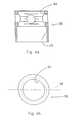
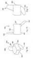
- implant 20includes first and second forked ends 22 and 24, each defining a saddle 26, 28 respectively.
- the forked ends 22, 24are mated using an interbody piece 30.
- the first forked end 22includes a threaded shaft 32 which projects rearwardly from the saddle 26.
- the threaded shaft 32fits into the threaded bore 34 (Fig. 4a) of the interbody piece 30.
- the second forked end 24(Figs. 5a, 5b) includes a smooth cylindrical shaft 36 which can fit into the smooth bore 38 of the interbody piece 30.
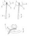
- Fig. 1shows the implant 20 in a fully extended position
- Fig. 2shows the implant in an unextended position.
- the threaded shaft 32 of the first forked end 22fits inside the hollow cylindrical shaft 36 of the second forked end 24.
- the implant 20For purposes of implantation between adjacent first and second spinous processes of the spinal column, the implant 20 is configured as shown in Fig. 2.
- the first and second spinous processesare exposed using appropriate surgical techniques and thereafter, the implant 20 is positioned so that saddle 26 engages the first spinous process, and saddle 28 engages the second spinous process.
- the interbody piece 30can be rotated by placing an appropriate tool or pin into the cross holes 40 and upon rotation, the saddle 26 is moved relative to the saddle 28.
- Such rotationspreads apart or distracts the spinous processes with the resultant and beneficial effect of enlarging the volume of the spinal canal in order to alleviate any restrictions on blood vessels and nerves.
- this implantas well as the several other implants described herein act as an extension stop. That means that as the back.is bent backwardly and thereby placed in extension the spacing between adjacent spinous processes cannot be reduced to a distance less than the distance between the lowest point of saddle 26 and the lowest point of saddle 28.
- This implantdoes not inhibit or in any way limit the flexion of the spinal column, wherein the spinal column is bent forward.
- such a deviceprovides for distraction in the range of about 5 mm to about 15 mm.
- devices which can distract up to and above 22 mmmay be used depending on the characteristics of the individual patient.
- the implant 20can be implanted essentially floating in position in order to gain the benefits of the aforementioned extension stop and flexion non-inhibitor.
- one of the saddles 26can be laterally pinned with pin 29 to one of the spinous processes and the other saddle can be loosely associated with the other spinous processes by using a tether 31 which either pierces or surrounds the other spinous process and then is attached to the saddle in order to position the saddle relative to the spinous process.
- both saddlescan be loosely tethered to the adjacent spinous process in order to allow the saddles to move relative to the spinous processes.
- the shape of the saddlesbeing concave, gives the advantage of distributing the forces between the saddle and the respective spinous process. This ensures that the bone is not resorbed due to the placement of the implant 20 and that the structural integrity of the bone is maintained.
- the implant 20 in this embodimentcan be made of a number of materials, including but not limited to, stainless steel, titanium, ceramics, plastics, elastics, composite materials or any combination of the above.
- the modulus of elasticity of the implantcan be matched to that of bone, so that the implant 20 is not too rigid.
- the flexibility of the implantcan further be enhanced by providing additional apertures or perforations throughout the implant in addition to the holes 40 which also have the above stated purpose of allowing the interbody piece 30 to be rotated in order to expand the distance between the saddle 26, 28.
- the spinous processescan be accessed and distracted initially using appropriate instrumentation, and that the implant 20 can be inserted and adjusted in order to maintain and achieve the desired distraction.
- the spinous processcan be accessed and the implant 20 appropriately positioned. Once positioned, the length of the implant can be adjusted in order to distract the spinous processes or extend the distraction of already distracted spinous processes.
- the implantcan be used to create a distraction or to maintain a distraction which has already been created.
- implant 20placement of implants such as implant 20 relative to the spinous process will be discussed hereinbelow with other embodiments. However, it is to be noted that ideally, the implant 20 would be placed close to the instantaneous axis of rotation of the spinal column so that the forces placed on the implant 20 and the forces that the implant 20 places on the spinal column are minimized.
- the methoduses the approach of extending the length of the implant 20 a first amount and then allowing the spine to creep or adjust to this distraction. Thereafter, implant 20 would be lengthened another amount, followed by a period where the spine is allowed to creep or adjust to this new level of distraction. This process could be repeated until the desired amount of distraction has been accomplished.
- This same methodcan be used with insertion tools prior to the installation of an implant. The tools can be used to obtain the desired distraction using a series of spinal distraction and spine creep periods before an implant is installed.
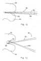
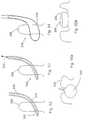
- the embodiment of the invention shown in the above Figs. 6, 7, 8, 9 and 10includes distraction or spreader tool 50 which has first and second arms 52, 54. Arms 52, 54 are pivotal about pivot point 56 and releaseable from pivot point 56 in order to effect the implantation of implant 58. As can be seen in Fig. 6, in cross-section, the arms 52, 54 are somewhat concave in order to cradle and securely hold the first spinous process 60 relative to arm 52 and the second spinous process 62 relative to arm 54.
- the distraction tool 50can be inserted through a small incision in the back of the patient in order to address the space between the first spinous process 60 and the second spinous process 62.
- the arms 52, 54can be spread apart in order to distract the spinous processes.
- an implant 58as shown in Figs. 8 and 9, or of a design shown in other of the embodiments of this invention, can be urged between the arms 52, 54 and into position between the spinous processes.
- the arms 52, 54can be withdrawn from the spinous processes leaving the implant 58 in place.
- the implant 58is urged into place using a tool 64 which can be secured to the implant 58 through a threaded bore 66 in the back of the implant. As can be seen in Fig.
- the implant 58includes saddles 68 and 70 which cradle the upper and lower spinous processes 60, 62 in much the same manner as the above first embodiment and also in much the same manner as the individual arms of the tool 50.
- the saddles as described abovetend to distribute the load between the implant and the spinous processes and also assure that the spinous process is stably seated at the lowest point of the respective saddles.
- the spreader or distraction tool 80includes first and second arms 82, 84 which are permanently pivoted at pivot point 86.
- the armsinclude L-shaped ends 88, 90.
- the L-shaped ends 88, 90can be inserted between the first and second spinous processes 92, 94.
- the arms 82, 84can be spread apart in order to distract the spinous processes.
- the implant 96can then be urged between the spinous processes in order to maintain the distraction.
- implant 96includes wedged surfaces or ramps 98, 100. As the implant 96 is being urged between the spinous processes, the ramps further cause the spinous processes to be distracted.
- the implant 96Once the implant 96 is fully implanted, the full distraction is maintained by the planar surfaces 99, 101 located rearwardly of the ramps. It is to be understood that the cross-section of the implant 96 can be similar to that shown for implant 58 or similar to other implants in order to gain the advantages of load distribution and stability.
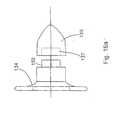
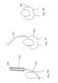
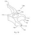
- the implant 110includes first and second conically shaped members 112, 114.
- Member 112includes a male snap connector 116 and member 114 includes a female snap connector 118. With male snap connector 116 urged into female snap connector 118, the first member 112 is locked to the second member 114.
- a distraction or spreader tool 80could be used.
- an implantation tool 120can be used to position and snap together the implant 110.
- the first member 112 of implant 110is mounted on one arm and second member 114 is mounted on the other arm of tool 120.
- the member 112, 114are placed on opposite sides of the space between adjacent spinous processes.
- the members 112, 114are urged together so that the implant 110 is locked in place between the spinous processes as shown in Fig. 15. It is to be noted that the implant 110 can also be made more self-distracting by causing the cylindrical surface 122 to be more conical, much as surface 124 is conical, in order to hold implant 110 in place relative to the spinous processes and also to create additional distraction.
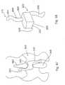
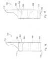
- FIGs. 16 and 17An alternative embodiment of the implant can be seen in Figs. 16 and 17.
- This implant 130includes first and second members 132, 134.
- the implantsare held together using a screw (not shown) which is inserted through countersunk bore 136 and engages a threaded bore 138 of the second member 134.
- Surfaces 139are flattened (Fig. 17) in order to carry and spread the load applied thereto by the spinous processes.
- the embodiment of implant 130is not circular in overall outside appearance, as is the embodiment 110 of Figs. 14 and 15.
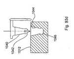
- this embodimentis truncated so that the lateral side 140, 142 are flattened with the upper and lower sides 144, 146 being elongated in order to capture and create a saddle for the upper and lower spinous processes.
- the upper and lower sides, 144, 146are rounded to provide a more anatomical implant which is compatible with the spinous processes.
- key 148 and keyway 150are designed to mate in a particular manner.
- Key 148includes at least one flattened surface, such as flattened surface 152, which mates to an appropriately flattened surface 154 of the keyway 150.
- the first memberis appropriately mated to the second member in order to form appropriate upper and lower saddles holding the implant 130 relative to the upper and lower spinous processes.
- Fig. 16adepicts second member 134 in combination with a rounded nose lead-in plug 135.
- Lead-in plug 135includes a bore 137 which can fit snugly over key 148. In this configuration, the lead-in plug 135 can be used to assist in the placement of the second member 134 between spinous processes. Once the second member 134 is appropriately positioned, the lead-in plug 135 can be removed. It is to be understood that the lead-in plug 135 can have other shapes such as pyramids and cones to assist in urging apart the spinous processes and soft tissues in order to position the second member 134.
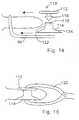
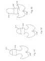
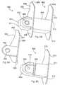
- the implant 330 as shown in Fig. 18is comprised of first and second mating wedges 332 and 334.
- the spinous processesare accessed from both sides and then a tool is used to push the wedges towards each other.
- the wedgesmove relative to each other so that the combined dimension of the implant 330 located between the upper and lower spinous processes 336, 338 (Fig. 20), increases, thereby distracting the spinous processes.
- the wedges 332, 334include saddle 340, 342, which receiving the spinous processes 336, 338. These saddles have the advantages as described hereinabove.
- the first or second wedges 332, 334have a mating arrangement which includes a channel 344 and a projection of 346 which can be urged into the channel in order to lock the wedges 332, 334 together.
- the channel 334is undercut in order to keep the projection from separating therefrom .
- a detentcan be located in one of the channel and the projection, with a complimentary recess in the other of the channel and the projection. Once these two snap together, the wedges are prevented from sliding relative to the other in the channel 344.
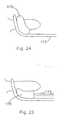
- the implant 370is comprised of first and second distraction cone 372, 374. These cones are made of a flexible material. The cones are positioned on either side of the spinous processes 376, 378 as shown in Fig. 21. Using appropriate tool as shown hereinabove, the distraction cones 372, 374 are urged together. As they are urged together, the cones distract the spinous processes as shown in Fig. 22. Once this has occurred, an appropriate screw or other type of fastening mechanism 380 can be used to maintain the position of the distraction cones 372, 374.
- the advantage of this arrangementis that the implant 370 is self-distracting and also that the implant, being flexible, molds about the spinous processes as shown in Fig. 22.
- FIGs. 23 and 24another embodiment of the implant 170 is depicted.
- This implantis guided in place using an L-shaped guide 172 which can have a concave cross-section such as the cross-section 52 of retraction tool 50 in Fig. 6 in order to cradle and guide the implant 170 in position.
- a small incisionwould be made into the back of the patient and the L-shaped guide tool 172 inserted between the adjacent spinous processes.
- the implant 170would be mounted on the end of insertion tool 174 and urged into position between the spinous processes. The act of urging the implant into position could cause the spinous processes to be further distracted if that is required.
- a distraction toolsuch as shown in Fig. 13 could be used to initially distract the spinous processes.
- Implant 170can be made of a deformable material so that it can be urged into place and so that it can somewhat conform to the shape of the upper and lower spinous processes.
- This deformable materialwould be preferably an elastic material. The advantage of such a material would be that the load forces between the implant and the spinous processes would be distributed over a much broader surface area. Further, the implant would mold itself to an irregular spinous process shape in order to locate the implant relative to spinous processes.
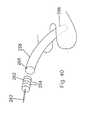
- this implant 176can be inserted over a guide wire, guide tool or stylet 178.
- the guide wire 178is positioned through a small incision to the back of the patient to a position between the adjacent spinous processes.
- the implantis threaded over the guide wire 178 and urged into position between the spinous processes. This urging can further distract the spinous processes if further distraction is required.
- the guide tool 178is removed and the incision closed.
- the insertion tools of Figs. 23 and 24can also be used if desired.
- FIGs. 26, 27 and 28uses an implant similar to that depicted in Figs. 8 and 9 with different insertion tools.
- an L-shaped distraction tool 190is similar to L-shaped distraction tool 80 (Fig. 12), is used to distract the first and second spinous processes 192, 194.
- an insertion tool 196is placed between the spinous processes 192, 194.
- Insertion tool 196includes a handle 198 to which is mounted a square-shaped ring 200.
- the distraction tool 190can be inserted through a small incision in the back in order to spread apart the spinous processes.
- an upper end 202 of ring 200can be initially inserted followed by the remainder of the ring 200.
- the ringcan be rotated slightly by moving handle 198 downwardly in order to further wedge the spinous processes apart.
- an implantsuch as implant 204 can be inserted through the ring and properly positioned using implant handle 206. Thereafter, the implant handle 206 and the insertion tool 196 can be removed.
- the implants 210, 212can have different shapes when viewed from the side. These implants are similar to the above-referenced implants 58 (Fig. 8) and 204 (Fig. 28). These implants have cross-sections similar to that shown in Fig. 10 which includes saddles in order to receive and hold the adjacent spinous processes.
- these implantscan be placed in different positions with respect to the spinous process 214.
- the implant 210is placed closest to the lamina 216. Being so positioned, the implant 210 is close to the instantaneous axis of rotation 218 of the spinal column, and the implant would experience least forces caused by movement of the spine. Thus, theoretically, this is the optimal location for the implant.
- the implantcan be placed midway along the spinous process (Fig. 32) and towards the posterior aspect of the spinous process (Fig. 31). As positioned shown in Fig. 31, the greatest force would be placed on the implant 210 due to a combination of compression and extension of the spinal column.
- implant 220is comprised of a plurality of individual leaves 222 which are substantially V-shaped.
- the leavesinclude interlocking indentations or detents 224. That is, each leaf includes an indentation with a corresponding protrusion such that a protrusion of one leaf mates with an indentation of an adjacent leaf.
- an insertion tool 226which has a blunt end 228 which conforms to the shape of an individual leaf 222. For insertion of this implant into the space between the spinous processes as shown in Fig. 29, the insertion tool 226 first insert a single leaf 220.
- the insertion toolthen inserts a second leaf with the protrusion 224 of the second leaf snapping into corresponding indentation made by the protrusion 224 of the first leaf.
- This processwould reoccur with third and subsequent leaves until the appropriate spacing between the spinous processes was built up.
- the lateral edges 229 of the individual leaves 222are slightly curved upwardly in order to form a saddle for receiving the upper and lower spinous processes.
- Implant 220is essentially a series of truncated cones and includes a plurality of ever expanding steps 236. These steps are formed by the conical bodies starting with the nose body 238 followed there behind by conical body 240. Essentially, the implant 234 looks like a fir tree placed on its side.
- the implant 230is inserted laterally throughout the opening between upper and lower spinous processes.
- the first body 238causes the initial distraction. Each successive conical body distracts the spinous processes a further incremental amount.
- the spinous processesare locked into position by steps 236.
- the initial nose body 238 of the implant and other bodies 240can be broken, snapped or sawed off if desired in order to minimize the size of the implant 230.
- the intersection between bodies such as body 238 and 240which is intersection line 242
- intersection line 244 between the bodies which remain between the spinous processeswould not need to be weaker, as there would be no intention that the implant would be broken off at this point.
- Fig. 37shows implant 232 positioned between upper and lower spinous processes.
- This implantis wedge-shaped or triangular shaped in cross-sectioned and includes bore pluralities 245 and 246. Through these bores can be placed locking pins 248 and 250. The triangular or wedged-shaped implant can be urged laterally between and thus distract the upper and lower spinous processes. Once the appropriate distraction is reached, pins 248, 250 can be inserted through the appropriate bores of the bore pluralities 245 and 246 in order to lock the spinous processes in a V-shaped valley formed by pins 248, 250 on the one hand and the ramped surface 233, 235 on the other hand.
- the implant 234has a triangular-shaped or wedge-shaped body similar to that shown in Fig. 32.
- tab 252, 254are pivotally mounted to the triangular shaped body 234. Once the implant 234 is appropriately positioned in order to distract the spinous processes to the desired amount, the tabs 252, 254 rotate into position in order to hold the implant 234 in the appropriate position.
- cannula 258is inserted through a small incision to a position between upper and lower spinous processes. Once the cannula is properly inserted, an implant 260 is pushed through the cannula 258 using an insertion tool 262.
- the implant 260includes a plurality of ribs or indentation 264 that assist in positioning the implant 260 relative to the upper and lower spinal processes. Once the implant 260 is in position, the cannula 258 is withdrawn so that the implant 260 comes in contact with and wedges between the spinous processes.
- the cannula 258is somewhat conical in shape with the nose end 266 being somewhat smaller than the distal end 268 in order to effect the insertion of the cannula into the space between the spinous processes.
- a plurality of cannulacan be used instead of one, with each cannula being slightly bigger than one before.
- the first smaller cannulawould be inserted followed by successively larger cannula being placed over the previous smaller cannula.
- the smaller cannulawould then be withdrawn from the center of the larger cannula. Once the largest cannula is in place, and the opening of the skin accordingly expanded, the implant, which is accommodated by only the larger cannula, is inserted through the larger cannula and into position.
- the precurved implant 270 in Figs. 41 and 42, and precurved implant 272 in Fig. 43have common introduction techniques which includes a guide wire, guide tool, or stylet 274.
- the guide wire 274is appropriately positioned through the skin of the patient and into the space between the spinous processes. After this is accomplished, the implant is directed over the guide wire and into position between the spinous processes.
- the precurved nature of the implantassist in (1) positioning the implant through a first small incision in the patient's skin on one side of the space between two spinous processes and (2) guiding the implant toward a second small incision in the patient's skin on the other side of the space between the two spinous processes.
- the implantincludes a conical introduction nose 276 and a distal portion 278. As the nose 276 is inserted between the spinous processes, this causes distraction of the spinous processes. Break lines 280, 282 are established at opposite sides of the implant 270. Once the implant is properly positioned over the guide wire between the spinous processes, the nose portion 276 and the distal portion 278 can be broken off along the break lines, through the above two incisions, in order to leave the implant 270 in position.
- break lines 280, 282can be provided on implant 270 so that the implant can continue to be fed over the guide wire 278 until the appropriate width of the implant 270 creates the desired amount of distraction.
- the break linescan be created by perforating or otherwise weakening the implant 270 so that the appropriate portions can be snapped or sawed off.
- this implantis similar in design to the implant 230 shown in Fig. 36.
- This implant 272 in Fig. 47is precurved and inserted over a guide wire 274 to a position between the spinous processes.
- sections of the implant 272can be broken, snapped or sawed off as described hereinabove in order to leave a portion of the implant wedged between the upper and lower spinous processes.
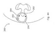
- FIG. 44A further embodiment of the invention is shown in Fig. 44.
- This embodimentincludes a combination insertion tool and implant 290.
- the insertion tool and implant 290is in the shape of a ring which is hinged at point 292.
- the ringis formed by a first elongated and conically shaped member 294 and a second elongated and conically shaped member 296.
- Members 294 and 296terminate in points and through the use of hinge 292 are aligned and meet.
- first member and second memberare inserted through the skins of the patient and are mated together between the spinous processes.
- the implant 290is rotated, for example clockwise, so that increasingly widening portions of the first member 292 are used to distract the first and second spinous processes.
- the remainder of the ring before and after the section which is located between the spinous processescan be broken off as taught hereinabove in order to maintain the desired distraction.
- the entire ringcan be left in place with the spinous processes distracted.
- the implant 300is comprised of a plurality of rods or stylets 302 which are inserted between the upper and lower spinous processes.
- the rodsare designed much as described hereinabove so that they may be broken, snapped or cut off. Once these are inserted and the appropriate distraction has been reached, the stylets are broken off and a segment of each stylet remains in order to maintain distraction of the spinous process.
- Implant 310 of Figs. 46 and 47is comprised of a shape memory material which coils upon being released.
- the materialis straightened out in a delivery tool 312.
- the delivery toolis in position between upper and lower spinous processes 314, 316.
- the materialis then pushed through the delivery tool.
- the materialcoils, distracting the spinous processes to the desired amount. Once this distraction has been achieved, the material is cut and the delivery tool removed.
- the implant 320is delivered between upper and lower spinous processes 322 and 324, by delivery tool 326.
- the delivery toolis given a 90° twist so that the implant goes from the orientation as shown in Fig. 49, with longest dimension substantially perpendicular to the spinous processes, to the orientation shown in Fig. 50 where the longest dimension is in line with and parallel to the spinous processes.
- This rotationcauses the desired distraction between the spinous processes.
- Implant 320includes opposed recesses 321 and 323 located at the ends thereof. Rotation of the implant 320 causes the spinous processes to become lodged in these recesses.
- the insertion tool 326can be used to insert multiple implants 320, 321 into the space between the spinous processes 322, 324 (Fig. 51). Multiple implants 320, 321 can be inserted until the appropriate amount of distraction is built up. It is to be understood in this situation that one implant would lock to another implant by use of, for example, a channel arrangement wherein a projection from one of the implants would be received into and locked into a channel of the other implant. Such a channel arrangement is depicted with respect to the other embodiment.
- Figs. 52 through 55bis comprised of a fluid-filled dynamic distraction implant 350.
- This implantincludes a membrane 352 which is placed over pre-bent insertion rod 354 and then inserted through an incision on one side of the spinous process 356.
- the bent insertion rod, with the implant 350 thereover,is guided between appropriate spinous processes. After this occurs, the insertion rod 354 is removed leaving the flexible implant in place.
- the implant 350is then connected to a source of fluid (gas, liquid, gel and the like) and the fluid is forced into the implant causing it to expand as shown in Fig. 54, distracting the spinal processes to the desired amount.
- the implant 350is closed off as is shown in Fig. 55a.
- the implant 350being flexible, can mold to the spinous processes which may be of irregular shape, thus assuring positioning. Further, implant 350 acts as a shock absorber, damping forces and stresses between the implant and the spinous processes.
- a variety of materialscan be used to make the implant and the fluid which is forced into the implant.
- viscoelastic substancessuch as methylcellulose, or hyaluronic acid can be used to fill the implant.
- materials which are initially a fluid, but later solidifycan be inserted in order to cause the necessary distraction. As the materials solidify, they mold into a custom shape about the spinous processes and accordingly are held in position at least with respect to one of two adjacent spinous processes.
- the implantcan be formed about one spinous process in such a manner that the implant stays positioned with respect to that spinous process (Fig. 55b).
- a single implantcan be used as an extension stop for spinous process located on either side, without restricting flexion of the spinal column.
- the implant 360 as shown in Fig. 56is comprised of a shape memory material such as a plastic or a metal.
- a curved introductory tool 362is positioned between the appropriate spinous processes as described hereinabove. Once this has occurred, bore 364 of the implant is received over the tool. This act can cause the implant to straighten out. The implant is then urged into position and thereby distracts the spinous processes. When this has occurred, the insertion tool 362 is removed, allowing the implant to assume its pre-straightened configuration and is thereby secured about one of the spinous processes.
- the implantcan be temperature sensitive. That is to say that the implant would be more straightened initially, but become more curved when it was warmed by the temperature of the patient's body.
- the implant 380is comprised of a plurality of interlocking leaves 382. Initially, a first leaf is positioned between opposed spinous processes 384, 386. Then subsequently, leafs 382 are interposed between the spinous processes until the desired distraction has been built up. The leaves are somewhat spring-like in order to absorb the shock and can somewhat conform to the spinous processes.
- the implant 390 of Fig. 61includes the placement of shields 392, 394 over adjacent spinous processes 396, 398.
- the shieldsare used to prevent damage to the spinous processes.
- These shieldsinclude apertures which receives a self-tapping screw 400, 402.
- the shieldsare affixed to the spinous processes and the spinous processes are distracted in the appropriate amount. Once this has occurred, a rod 404 is used to hold the distracted position by being screwed into each of the spinous processes through the aperture in the shields using the screws as depicted in Fig. 61.
- Implant 410 of Figs. 62, 63is comprised of first and second members 412, 414 which can be mated together using an appropriate screw and threaded bore arrangement to form the implant 410.
- Main member 412 and mating member 414form implant 410.
- the implant 410would have a plurality of members 414 for use with a standardized first member 412.
- Figs. 62 and 64show different types of mating members 414.
- the mating member 414includes projections 416 and 418 which act like shims. These projections are used to project into the space of saddles 420, 422 of the first member 412. These projections 416, 418 can be of varying lengths in order to accommodate different sizes of spinous processes.
- a groove 424is placed between the projections 416, 418 and mates with an extension 426 of the first member 412.
- Figs. 64, 65 and 66are similar in design and concept to the embodiment of Figs. 62 and 63.
- the implant 500includes the first and second members 502, 504. These members can be secured together with appropriate screws or other fastening means as taught in other embodiments.
- Implant 500includes first and second saddles 506, 508 which are formed between the ends of first and second members 502, 504. These saddles 506, 508 are used to receive and cradle the adjacent spinous processes. As can be seen in Fig. 64, each saddle 506, 508 is defined by a single projection or leg 510, 512, which extends from the appropriate first and second members 502, 504. Unlike the embodiment found in Figs.
- each of the saddlesis defined by only a single leg as the ligaments and other tissues associated with the spinous processes can be used to ensure that the implant is held in an appropriate position.
- Fig. 64it is easier to position the implant relative to the spinous processes as each saddle is defined by only a single leg and thus the first and second members can be more easily worked into position between the various tissues.
- the implant 520is comprised of a single piece having saddles 522 and 524.
- the saddlesare defined by a single leg 526, 528 respectively.
- an incisionis made between lateral sides of adjacent spinous processes.
- the single leg 526is directed through the incision to a position adjacent to an opposite lateral side of the spinous process with the spinous process cradled in the saddle 522.
- the spinous processesare then urged apart until saddle 524 can be pivoted into position into engagement with the other spinous process in order to maintain the distraction between the two adjacent spinous processes.
- Fig. 66is similar to that of Fig. 65 with an implant 530 and first and second saddles 532 and 534. Associated with each saddle is a tether 536, 538 respectively.
- the tethersare made of flexible materials known in the trade and industry and are positioned through bores in the implant 530. Once appropriately positioned, the tethers can be tied off. It is to be understood that the tethers are not meant to be used to immobilize one spinous process relative to the other, but are used to guide motion of the spinous processes relative to each other so that the implant 530 can be used as an extension stop and a flexion non-inhibitor.
- the saddles 532, 534are used to stop spinal column backward bending and extension. However, the tethers do not inhibit forward bending and spinal column flexion.
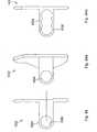
- the implant 550is Z-shaped and includes a central body 552 and first and second arms 554, 556, extending in opposite directions therefrom.
- the central body 552 of the implant 550includes first and second saddles 558 and 560.
- the first and second saddles 558 and 560would receive upper and lower spinous processes 562, 568.
- the arms 554, 556are accordingly located adjacent the distal end 566 (Fig. 68) of the central body 552.
- the first and second arms 554, 556act to inhibit forward movement, migration or slippage of the implant 550 toward the spinal canal and keep the implant in place relative to the first and second spinal processes. This prevents the implant from pressing down on the ligamentum flavum and the dura.
- the central bodywould have a height of about 10mm with each of the arms 554, 556 have a height of also about 10mm. Depending on the patient, the height of the body could vary from about less than 10 mm to about greater than 24mm.
- the first and second arms 554, 556are additionally contoured in order to accept the upper and lower spinous processes 556, 558.
- the arms 554, 556 as can be seen with respect to arm 554have a slightly outwardly bowed portion 568 (Fig. 68) with a distal end 570 which is slightly inwardly bowed.
- This configurationallows the arm to fit about the spinous process with the distal end 570 somewhat urged against the spinous process in order to guide the motion of the spinous process relative to the implant.
- These arms 554, 556could if desired to be made more flexible than the central body 552 by making arms 554, 556 thin and/or with perforations, and/or other material different than that of the central body 550.
- this embodimentcan be urged into position between adjacent spinous processes by directing an arm into a lateral incision so that the central body 552 can be finally positioned between spinous processes.
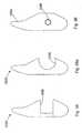
- Figs. 69, 70 and 71are perspective front, end, and side views of implant 580 of the invention.
- This implantincludes a central body 582 which has first and second saddles 584, 586 for receiving adjacent spinous processes. Additionally, the implant 580 includes first and second arms 588 and 590. The arms, as with the past embodiment, prevent forward migration or slippage of the implant toward the spinal canal.
- First arm 588projects outwardly from the first saddle 584 and second arm 590 projects outwardly from the second saddle 586.
- the first arm 588is located adjacent to the distal end 600 of the central body 582 and proceeds only partly along the length of the central body 582.
- the first arm 588is substantially perpendicular to the central body as shown in Fig. 70. Further, the first arm 588, as well as the second arm 590, is anatomically rounded.
- the second arm 590projecting from second saddle 586, is located somewhat rearward of the distal end 600, and extends partially along the length of the central body 582.
- the second arm 590projects at a compound angle from the central body 582.
- the second arm 590is shown to be at about an angle of 45° from the saddle 586 (Fig. 70). Additionally, the second arm 590 is at an angle of about 45° relative to the length of the central body 580 as shown in Fig. 71. It is to be understood that other compound angles are within the spirit and scope of the invention as claimed.
- the first and second arms 588, 590have a length which is about the same as the width of the central body 582.
- the length of each armis about 10mm and the width of the central body is about 10mm.
- the bodies with the widths of 24mm and greaterare within the spirit and scope of the invention, along with first and second arms ranging from about 10mm to greater than about 24mm.
- the embodimentcould include a central body having a width of about or greater than 24mm with arms being at about 10mm.
- Figs. 69, 70 and 71are designed to preferably be positioned between the L4-L5 and the L5-S1 vertebral pairs.
- the embodiment of Figs. 69, 70, 71is particularly designed for the L5-S1 position with the arms being designed to conform to the sloping surfaces found therebetween. The first and second arms are thus contoured so that they lie flat against the lamina of the vertebra which has a slight angle.
- Fig. 69, 70, and 71as with the embodiment of Figs. 67 and 68 is Z-shaped in configuration so that it may be inserted from one lateral side to a position between adjacent spinous processes. A first arm, followed by the central body, is guided through the space between the spinous processes. Such an arrangement only requires that a incision on one side of the spinous process be made in order to successfully implant the device between the two spinous processes.
- the implant 610 of Fig. 71 ais similar to that immediately above with the first arm 612 located on the same side of the implant as the second arm 614.
- the first and second saddle 616, 618are slightly modified in that distal portion 620, 622 are somewhat flattened from the normal saddle shape in order to allow the implant to be positioned between the spinous processes from one side. Once in position, the ligaments and tissues associated with the spinous processes would hold the implant into position. Tethers also could be used if desired.
- Implant 630is also designed so that it can be inserted from one side of adjacent spinous processes.
- This insert 630includes a central body 632 with the first and second arms 634, 636 extending on either side thereof.
- a plunger 638is positioned to extend from an end of the central body 632.
- the plunger 638is fully extended and as shown in Fig. 73, the plunger 638 is received within the central body 632 of the implant 630.
- the third and fourth arms or hooks 640, 642can extend outwardly from the central body 632.
- the third and fourth arms or hooks 640, 642can be comprised of a variety of materials, such as for example, shape memory metal materials or materials which have a springy quality.
- the plunger 638is pulled outwardly as shown in Fig. 72.
- the central body 632is then positioned between adjacent spinous processes and the plunger 638 is allowed to move to the position of Fig. 73 so that the third and fourth arms 640, 642 can project outwardly from the central body 632 in order to hold the implant 630 in position between the spinous processes.
- Plunger 638can be spring biased to the position as shown in Fig. 73 or can include detents or other mechanisms which lock it into that position. Further, the third and fourth arms themselves, as deployed, can keep the plunger in the position as shown in Fig. 73.
- FIGs. 74 through 78Other embodiments of the invention are shown in Figs. 74 through 78.
- Figs. 74, 75 and 76disclose implant 700.
- Implant 700is particularly suited for implantation between the L4-L5 and L5-S1 vertebra.
- the implant 700includes a central body 702 which has a bore 704 provided therein.
- Bore 704is used in order to adjust the modulus of elasticity of the implant so that it is preferably approximately two times the anatomical load placed on the vertebra in extension.
- the implant 700is approximately two times stiffer than the normal load placed on the implant.
- Such an arrangementis made in order to ensure that the implant is somewhat flexible in order to reduce potential resorption of the bone adjacent to the implant.
- Other modulus valuescan be used and be within the spirit of the invention.
- Implant 700includes first and second saddle 706, 708 which are used to receive and spread the load from the upper and lower spinous processes.
- the saddle 706is defined by first and second arms 710 and 712.
- the second saddle 708is defined by third and fourth arms 714 and 716.
- the first arm 710in a preferred embodiment, is approximately two times the length of the body 702 with the second arm being approximately less than a quarter length of the body.
- Third arm 714is approximately one times the length of the body 702 with the fourth arm 716 being, in this preferred embodiment, approximately one and a half times the length of the body 702.
- the armsare designed in such a way that the implant (1) can be easily and conveniently inserted between the adjacent spinous processes, (2) will not migrate forwardly toward the spinal canal, and (3) will hold its position through flexion and extension as well as lateral bending of the spinal column.
- First arm 710is in addition designed to accommodate the shape of the vertebra. As can be seen in Fig. 74, the first arm 710 becomes narrower as it extends away from the body 702.
- the first arm 710includes a sloping portion 718 followed by a small recess 720 ending in a rounded portion 722 adjacent to the end 724.
- This designis provided to accommodate the anatomical form of for example the L4 vertebra. It is to be understood that these vertebra have a number of surfaces at roughly 30° angles and that the sloping surfaces of this embodiment and the embodiments shown in Figs. 77 and 78 are designed to accommodate these surfaces. These embodiments can be further modified in order to accommodate other angles and shapes.
- the second arm 712is small so that it is easy to insert between the spinous processes, yet still define the saddle 706.
- the fourth arm 716is larger than the third arm 714, both of which are smaller than the first arm 710.
- the third and fourth armsare designed so that they define the saddle 706, guide the spinous processes relative to the implant 700 during movement of the spinal column, and yet are of a size which makes the implant easy to position between the spinous processes.
- the procedure, by way of example only, for implanting the implant 700can be to make an incision laterally between two spinous processes and then initially insert first arm 710 between the spinous processes.
- the implant and/or appropriate toolswould be used to distract the spinous processes allowing the third leg 714 and the central body 702 to fit through the space between the spinous processes.
- the third leg 714would then come to rest adjacent the lower spinous processes on the opposite side with the spinous processes resting in the first and second saddle 706, 708.
- the longer fourth leg 716would then assist in the positioning of the implant 700.
- Fig. 77includes an implant 740 which is similar to implant 700 and thus have similar numbering.
- the saddle 706, 708 of implant 740have been cantered or sloped in order to accommodate the bone structure between, by way of example, the L4-L5 and the L5-S1 vertebra.
- the vertebra in this areahave a number of sloping surfaces in the range of about 30°. Accordingly, saddle 706 is sloped at less than 30° and preferably about 20° while saddle 708 is sloped at about 30° and preferably more than 30°.
- Implant 760 as shown in Fig. 78is similar to implant 700 in Fig. 74 and is similarly numbered.
- Implant 760includes third and fourth legs 714, 716 which have sloping portions 762, 764 which slope toward ends 766, 768 of third and fourth arm 714, 716 respectively.
- the sloping portionsaccommodate the form of the lower vertebra against which they are positioned. In the preferred embodiment, the sloping portions are of about 30°. However, it is to be understood that sloping portions which are substantially greater and substantially less than 30° can be included and be within the spirit and scope of the invention.
- Implant 800includes a distracting unit 802 which is shown in left side, plan, and right side views of Figs. 79, 80 and 81.
- a perspective view of the distraction unitis shown in Fig. 84.
- the distracting unit as can be seen in Fig. 80includes a distracting body 804, with longitudinal axis 805, which body 804 has a groove 806 and a rounded or bulbous end 808 which assist in the placement of the distracting body between adjacent spinous process so that an appropriate amount of distraction can be accomplished.
- Extending from the distracting body 804is a first wing 810 which in Fig. 80 is substantially perpendicular to the distracting body 804.
- First wing 810includes a upper portion 812 and a lower portion 814.
- the upper portion 810(Figs. 79) includes a rounded end 816 and a small recess 818.
- the rounded end 816 and the small recess 818 in the preferred embodimentare designed to accommodate the anatomical form or contour of the L4 (for a L4-L5 placement) or L5 (for a L5-S1 placement) superior lamina of the vertebra. It is to be understood that the same shape or variations of this shape can be used to accommodate other lamina of any vertebra.
- the lower portion 814is also rounded in order to accommodate in the preferred embodiment in order to accommodate the vertebrae.
- the distracting unitfurther includes a threaded bore 820 which in this embodiment accepts a set screw 822 (Fig. 86) in order to hold a second wing 824 (Figs. 82, 83) in position as will be discussed hereinbelow.
- the threaded bore 820 in this embodimentslopes at approximately 45° angle and intersects the slot 806. With the second wing 824 in position, the set screw 822 when it is positioned in the threaded bore 820 can engage and hold the second wing 824 in position in the slot 806.
- the second wing 824is similar in design to the first wing.
- the second wingincludes an upper portion 826 and a lower portion 828.
- the upper portionincludes a rounded end 830 and a small recess 832.
- the second wing 824includes a slot 834 which mates with the slot 806 of the distracting unit 802.
- the second wing 824is the retaining unit of the present embodiment.
- the second wing or retaining unit 824includes the upper portion 826 having a first width "a" and the lower portion 828 having a second width "b".
- the second width "b"is larger than first width "a” due to the anatomical form or contour of the L4-L5 or L5-S1 laminae.
- the widths "a" and “b”would be increased in order to, as described hereinbelow, accommodate spinous processes and other anatomical forms or contours which are of different dimensions. Further, as appropriate, width "a" can be larger than width "b".
- the implantcan include a universally-shaped distracting unit 802 with a plurality of retaining units 824, with each of the retaining units having different widths "a” and "b".
- the appropriately sized retaining unit 824, width with the appropriate dimensions "a” and “b”can be selected to match to the anatomical form of the patient.
- Fig. 86depicts an assembled implant 800 positioned adjacent to upper and lower laminae 836, 838 (which are shown in dotted lines) of the upper and lower vertebrae.
- the vertebrae 836, 838are essentially below the implant 800 as shown in Fig. 86.
- the fit of the implant between the spinous processescan be such that the wings do not touch the spinous processes, as shown in Fig. 86, and be within the spirit and scope of the invention.
- the implant 800includes, as assembled, an upper saddle 844 and the lower saddle 846.
- the upper saddle 844has an upper width identified by the dimension "UW”.
- the lower saddle 846has a lower width identified by the dimension "LW”. In a preferred embodiment, the upper width is greater than the lower width. In other embodiments, the "UW" can be smaller than the "LW” depending on the anatomical requirements.
- the height between the upper and lower saddles 844, 846is identified by the letter “h”.
- Fig. 87is a schematic representation of the substantially trapezoidal shape which is formed between the upper and lower saddles.
- the table belowgives sets of dimensions for the upper width, lower width, and height as shown in Fig. 87. This table includes dimensions for some variations of this embodiment. TABLE Variation 1 2 3 Upper Width 8 7 6 Lower Width 7 6 5 Height 10 9 8 For the above table, all dimensions are given in millimeters.
- the patientis preferably positioned on his side (arrow 841 points up from an operating table) and placed in a flexed (tucked) position in order to distract the upper and lower vertebrae.
- a small incisionis made on the midline of the spinous processes.
- the spinous processesare spread apart or distracted with a spreader.
- the incisionis spread downwardly toward the table, and the distracting unit 802 is preferably inserted upwardly between the spinous processes 840 and 842 in a manner that maintains the distraction of spinous processes.
- the distracting unit 802is urged upwardly until the distracting or bulbous end 808 and the slot 806 are visible on the other wide of the spinous process. Once this is visible, the incision is spread upwardly away from the table and the retaining unit or second wing 824 is inserted into the slot 806 and the screw 822 is used to secure the second wing in position. After this had occurred, the incisions can be closed.
- An alternative surgical approachrequires that small incisions be made on either side of the space located between the spinous processes.
- the spinous processesare spread apart or distracted using a spreader placed through the upper incision.
- the distracting unit 802is preferably inserted upwardly between the spinous processes 840 and 842 in a manner that urges the spinous processes apart.
- the distracting unit 802is urged upwardly until the distracting or bulbous end 808 and the slot 806 are visible through the second small incision in the patient's back. Once this is visible, the retaining unit or second wing 824 is inserted into the slot 806 and the screw 822 is used to secure the second wing in position. After this has occurred, the incisions can be closed.
- Fig. 80ashows an alternative embodiment of the distracting unit 802a.
- This distracting unit 802ais similar to distracting unit 802 in Fig. 80 with the exception that the bulbous end 808a is removable from the rest of the distracting body 804a as it is screwed into the threaded bore 809. The bulbous end 808a is removed once the distracting unit 802a is positioned in the patient in accordance with the description associated with Fig. 86.
- the bulbous end 808acan extend past the threaded bore 820 by about 1 cm in a preferred embodiment.
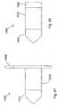
- FIG. 88, 89, 90 and 91Another embodiment of the invention is shown in Figs. 88, 89, 90 and 91.
- the implantis identified by the number 900.
- Other elements of implant 900 which are similar to implant 800are similarly numbered but in the 900 series.
- the distracting unitis identified by the number 902 and this is in parallel with the distracting unit 802 of the implant 800.
- the distracting bodyis identified by the number 904 in parallel with the distracting body 804 of the implant 800. Focusing on Fig. 90, the distracting unit 902 is depicted in a perspective view.
- the distracting unitincludes slot 906 which is wider at the top than at the bottom. The reason for this is that the wider upper portion of the slot 906, which is wider than the second wing 924 (Fig.
- the end 908 of implant 900is different in that it is more pointed, having sides 909 and 911 which are provided at about 45° angles (other angles, such as by way of example only, from about 30° to about 60° are within the spirit of the invention), with a small flat tip 913 so that the body 904 can be more easily urged between the spinous processes.
- the distracting unit 902further includes a tongue-shaped recess 919 which extends from the slot 906. Located in the tongue-shaped recess is a threaded bore 920.
- a second wing 924includes a tongue 948 which extends substantially perpendicular thereto and between the upper and lower portions 926, 928.
- the tab 948includes a bore 950.
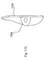
- the implant 1000 as can be seen in Fig. 92aincludes a central elongated body 1002 which has positioned at one end thereof a first wing 1004.
- Wing 1004is similar to the first wing previously described with respect to the embodiment of Fig. 88.
- Bolt 1006secures wing 1004 to body 1002 in this embodiment.
- Bolt 1006is received in a bore of the body 1002 which is along the longitudinal axis 1008 of body.
- the first unitis defined by the central body 1002, the first wing 1004, and the guide 1010.
- the first winghas a protrusion 1040 extending preferably about perpendicularly from the first wing, with a flexible catch 1042.
- the protrusion and flexible catchare press fit into a bore 1044 of the central body with the catch received in a detent 1046.
- the first wingcan be designed as shown in Fig. 93d with the protrusion directed substantially parallel to the first wing from a member that joins the first wing to the protrusion.
- the first wingis inserted into the body along the same direction as the second wing is inserted.
- guide 1010Positioned at the other end of the central body 1002 is a guide 1010.
- guide 1010is essentially triangularly-shaped so as to be a pointed and arrow-shaped guide.
- guide 1010could be in the shape of a cone with lateral truncated sides along the longitudinal axis 1008.
- Guide 1010includes a recess 1012 having a threaded bore 1014. Recess 1012 is for receiving a second wing 1032 as will be described hereinbelow.
- the guide 1010can be bulbous, cone-shaped, pointed, arrow-shaped, and the like, in order to assist in the insertion of the implant 1000 between adjacent spinous processes. It is advantageous that the insertion technique disturb as little of the bone and surrounding tissue or ligaments as possible in order to (1) reduce trauma to the site and facilitate early healing, and (2) not destabilize the normal anatomy. It is to be noted that with the present embodiment, there is no requirement to remove any of the bone of the spinous processes and depending on the anatomy of the patient, there may be no requirement to remove or sever ligaments and tissues immediately associated with the spinous processes.
- the implant 1000further includes a sleeve 1016 which fits around and is at least partially spaced from the central body 1002.
- the implantmay be comprised of a bio-compatible material such as titanium
- the sleeveis comprised preferably of a super-elastic material which is by way of example only, a nickel titanium material (NiTi), which has properties which allow it to withstand repeated deflection without fatigue, while returning to its original shape.
- NiTinickel titanium material
- the sleevecould be made of other materials, such as for example titanium, but these materials do not have the advantages of a super-elastic material.
- Fig. 93ais a cross-section through the implant 1000 depicting the central body 1002 and the sleeve 1016.
- both the central body 1002 and the sleeve 1016are substantially cylindrical and oval or ecliptically-shaped.
- An oval or elliptical shapeallows more of the spinous process to be supported by the sleeve, thereby distributing the load between the bone and the sleeve more evenly. This reduces the possibility of fracture to the bone or bone resorption.
- an oval or elliptical shapeenhances the flexibility of the sleeve as the major axis of the sleeve, as described below, is parallel to the longitudinal direction of the spinous process.
- other shapessuch as round cross-sections can come within the spirit and scope of the invention.
- the central body 1002includes elongated grooves 1018, along axis 1008, which receives elongated spokes 1020 extending from the internal surface of the cylinder 1016.
- both the cross-section of the central body and the sleevehave a major dimension along axis 1022 and a minor dimensional along axis 1024 (Fig. 93a).
- the spokes 1020are along the major dimension so that along the minor dimension, the sleeve 1016 can have its maximum inflection relative to the central body 1002.
- the central body along the minor dimension 1024can have multiple sizes and can, for example, be reduced in thickness in order to increase the ability of the sleeve 1016 to be deflected in the direction of the central body 1002.
- the central body 1002can include the spokes 1020 and the sleeve 1016 can be designed to include the grooves 1018 in order to appropriately space the sleeve 1016 from the central body 1002.
- the sleevecan have minor and major dimensions as follows: Minor Dimension Major Dimension 6 mm 10 mm 8 mm 10.75 mm 12 mm 14 mm 6 mm 12.5 mm 8 mm 12.5 mm 10 mm 12.5 mm
- said sleevehas a cross-section with a major dimension and a minor dimension and said major dimension is greater than said minor dimension and less than about two times said minor dimension.
- said guidehas a cross-section which is adjacent to said sleeve with a guide major dimension about equal to said sleeve major dimension and a guide minor dimension about equal to said sleeve minor dimension. Further in said embodiment, said guide extends from said central body with a cross-section which reduces in size in a direction away from said central body.
- said guideis cone-shaped with a base located adjacent to said sleeve. Further, said guide has a base cross-section about the same as the oval cross-section of said sleeve.
- a major dimension of the sleevecorrespond with a major dimension of the central body and a minor dimension of the sleeve corresponds with a minor dimension of the central body.
- the major dimension of the sleeve 1016is substantially perpendicular to a major dimension of the first wing 1004 along longitudinal axis 1030 (Fig. 92a). This is so that as discussed above, when the implant 1000 is properly positioned between the spinous processes, a major portion of the sleeve comes in contact with both the upper and lower spinous processes in order to distribute the load of the spinous processes on the sleeve 1016 during spinal column extension.
- the preferred material for the sleeve 1016is a super-elastic material and more preferably one comprised of an alloy of nickel and titanium. Such materials are available under the trademark Nitinol. Other super-elastic materials can be used as long as they are bio-compatible and have the same general characteristics of super-elastic materials.
- a preferred super-elastic materialis made up of the following composition of nickel, titanium, carbon, and other materials as follows: Nickel 55.80% by weight Titanium 44.07% by weight Carbon ⁇ 0.5% by weight Oxygen ⁇ 0.5% by weight
- this composition of materialsis able to absorb about 8% recoverable strain.
- This materialcan be repeatably deflected toward the central body and returned to about its original shape without fatigue.
- this materialcan withstand the threshold stress with only a small amount of initial deforming strain and above the threshold stress exhibit substantial and about instantaneous deformation strain which is many times the small amount of initial deforming strain.
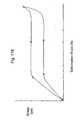
- Fig. 118shows a loading and unloading curve between stress and deformation strain for a typical type of super-elastic material as described above.
- the above super-elastic materialis selected to allow deformation of up to about, by way of example only, 8%, at about 20 lbs. to 50 lbs. force applied between a spinous processes. This would cause a sleeve to deflect toward the central body absorbing a substantial amount of the force of the spinous processes in extension.
- the sleevesare designed to absorb 20 lbs. to 100 lbs. before exhibiting the super-elastic effect (threshold stress level) described above.
- the sleevecan be designed for a preferable range of 20 lbs. to 500 lbs.
- the wall thickness of the sleeveis about 1 mm or 40/1000 of an inch (.040 in.).
- the sleeveis designed to experience a combined 1 mm deflection.
- the combined 1 mm deflectionmeans that there is 1 ⁇ 2 mm of deflection at the top of the minor dimension and a 1 ⁇ 2 mm deflection at the bottom of the minor dimension. Both deflections are toward the central body.
- a 20 lb. loadcauses a 0.005 in. deflection and a 60 lb. load causes a 0.020 in. deflection (approximately1 ⁇ 2 mm).
- a 100 lb. loadwould cause a deflection of about 0.04 in. or approximately 1 mm.
- the above preferred super-elastic materialmeans that the sleeve can be repeatedly deflected and returned to about its original shape without showing fatigue.
- the sleevecan withstand a threshold stress with a small amount of deforming strain and at about said threshold stress exhibit about substantially instantaneous deformation strain which is many times the small amount of the forming strain.
- such super-elastic qualitiesmean that the material experiences a plateau stress where the material supports a constant force (stress) over very large strain range as exhibited in Fig. 118.
- bar stock of the super-elastic materialis machined into the appropriate form and then heat treated to a final temperature to set the shape of the material by increasing the temperature of the material to 932° Fahrenheit and holding that temperature for five (5) minutes and then quickly quenching the sleeve in water.
- the present nickel titanium super-elastic alloyis selected to have a transition temperature A, of about 59° Fahrenheit (15°C). Generally for such devices the transition temperature can be between 15°C to 65°C (59°F to 149°F), and more preferably 10°C to 40°C (50°F to 104°F).
- the materialis maintained in the body above the transition temperature in order to exhibit optimal elasticity qualities.
- the sleevecan be fabricated by wire Electrical Discharge Machining (EDM) rather than machined. Additionally, the sleeve can be finished using a shot blast technique in order to increase the surface strength and elasticity of the sleeve.
- EDMElectrical Discharge Machining
- Second wing 1032as in several past embodiments includes a tab 1034 with a bore 1036 which aligns with the bore 1014 of the guide 1010.
- the second wing 1032includes a cut-out 1038 which is sized to fit over the guide 1010, with the tab 1034 resting in the recess 1012 of the guide 1010.
- FIG. 94aAn alternative configuration of the second wing 1032 is depicted in Fig. 94a.
- the second wing 1032is held at acute angle with respect to the tab 1034. This is different from the situation in the embodiment of Figs. 94 and 95 where the second wing is substantially perpendicular to the tab.
- Fig. 94asuch embodiment will be utilized as appropriate depending on the shape of the spinous processes.
- elongated tab 1034has a plurality of closely positioned bores 1036.
- the bores, so positioned,appear to form a scallop shape.
- Each individual scallop portion of the bore 1036can selectively hold the bolt in order to effectively position the second wing 1032 in three different positions relative to the first wing 1004.
- the cut-out 1038(Fig. 95a of this alternative embodiment) is enlarged over that of Fig. 95 as in a position closest to the first wing 1004, the second wing 1032 is immediately adjacent and must conform to the shape of the sleeve 1016.
- Implant 1050 of Fig. 97is similar to the implant 1000 in Fig. 92 with the major difference being that a second wing is not required.
- the implant 1050includes a central body as does implant 1000.
- the central bodyis surrounded by a sleeve 1016 which extends between a first wing 1004 and a guide 1010.
- the guide 1010 in this embodimentis substantially cone-shaped without any flats and with no bore as there is no need to receive a second wing.
- the sleeve and the central body as well as the first wing and guideact in a manner similar to those parts of the implant 1000 in Fig. 92. It is to be understood a cross-section of this implant 1050 through sleeve 1016 can preferably be like Fig. 93a.
- This particular embodimentwould be utilized in a situation where it was deemed impractical or unnecessary to use a second wing.
- This embodimenthas the significant advantages of the sleeve being comprised of super-elastic alloy materials as well as the guide being utilized to guide the implant between spinous processes while minimizing damage to the ligament and tissue structures found around the spinous processes.
- Implant 1060is depicted in Fig. 98. This implant is similar to the implants 1000 of Fig. 92 and the implant 1050 of Fig. 97, except that this implant does not have either first or second wings.
- Implant 1060includes a sleeve 1016 which surrounds a central body just as central body 1002 of implant 1000 in Fig. 93. it is to be understood that a cross-section of this implant 1060 through sleeve 1016 can preferably be like Fig. 93a.
- Implant 1060includes a guide 1010 which in this preferred embodiment is cone-shaped. Guide 1010 is located at one end of the central body. At the other end is a stop 1062.
- Stop 1062is used to contain the other end of the sleeve 1016 relative to the central body.
- This embodimentis held together with a bolt such as bolt 1006 of Fig. 93 that is used for the immediate above two implants.
- a boltsuch as bolt 1006 of Fig. 93 that is used for the immediate above two implants.
- the implant 1060 of Fig. 98such a device would be appropriate where the anatomy between the spinous processes was such that it would be undesirable to use either a first or second wing.
- this embodimentaffords all the advantageous described hereinabove (Figs. 92 and 97) with respect to the guide and also with respect to the dynamics of the sleeve.
- Implant system 1070includes a sleeve 1072 which is similar to and has the advantageous of sleeve 1016 of the embodiment in Fig. 92. Sleeve 1072 does not, however, have any spokes. Additionally, implant system 1070 includes an insertion tool 1074. Insertion tool 1074 includes a guide 1076 which in a preferred embodiment is substantially cone-shaped. Guide 1076 guides the insertion of the sleeve 1072 and the insertion tool 1074 between adjacent spinous processes. The insertion tool 1074 further includes a central body 1078, a stop 1080, and a handle 1082.
- the guide 1076 at its basehas dimensions which are slightly less than the internal dimensions of the sleeve 1074 so that the steeve can fit over the guide 1076 and rest against the stop 1080.
- the tool 1074 with the guide 1076is used to separate tissues and ligaments and to urge the sleeve 1072 in the space between the spinous processes. Once positioned, the guide insertion tool 1074 can be removed leaving the sleeve 1072 in place. If desired, after the sleeve is positioned, position maintaining mechanisms such as springy wires 1084 made out of appropriate material such as the super-elastic alloys and other materials including titanium, can be inserted using a cannula through the center of the sleeve 1072.
- the ends of the retaining wires 1084extend out of both ends of the sleeve 1072, and due to this springy nature, bent at an angle with respect to the longitudinal axis of the sleeve 1072. These wires help maintain the position of the sleeve relative to the spinous processes.
- FIG. 101Another embodiment of the invention can be seen in Fig. 101 which includes implant 1100.
- Implant 1100has many similar features that are exhibited with respect to implant 1000 in Fig. 92. Accordingly, elements with similar features and functions would be similarly numbered. Additionally, features that are different from implant 1100 can be, if desired, imported into and become a part of the implant 1000 of Fig. 92.
- implant 1100includes a central body 1002 (Fig. 102) with a first wing 1004 and a bolt 1006 which holds the first wing and the central body together.
- the central bodyis made in two portions.
- the first portion 1102is in the shape of a truncated cone with an oval or elliptical base and a second portion 1104 includes a cylindrical central portion with a distal end in the shape of a truncated cone 1103 with an oval or elliptical base.
- formed with the central bodyis the guide 1010 which has an oval or elliptical base.
- Bolt 1006is used to secure the first wing through the second portion 1104 with the first portion 1102 held in-between.
- the guide 1010in addition to including recess 1012 and bore 1014 includes a groove 1106 which receives a portion of the second wing 1032.
- the sleeve 1016is preferably oval or elliptical in shape as can be seen in Fig. 102a.
- the central bodycan be oval, elliptical or circular in cross-section, although other shapes are within the spirit and scope of the invention.
- the sleeve 1016held in position due to the fact that the truncated conical portion 1102 and the corresponding truncated conical portion 1103 each have a base that is elliptical or oval in shape.
- the sleeveis held in position so that preferably the major dimension of the elliptical sleeve is substantially perpendicular to the major dimension of the first wing.
- first wingis meant to be put beside the vertebrae so that the first wing is set at an angle other than perpendicular with respect to the vertebrae and that the sleeve may be held in a position so that the major dimension of the sleeve is at an angle other than perpendicular to the major dimension of the first wing and be within the spirit and scope of the invention.
- the major dimension of the sleevewould be preferably positioned so that it is essentially parallel to the length of the adjacent spinous processes. So configured, the elliptical or oval shape sleeve would bear and distribute the load more evenly over more of its surface.
- the sleeve in this embodimenthas all the characteristics and advantages described hereinabove with respect to the above-referenced super-elastic sleeves.
- the second wing as discussed abovecan come in a variety of shapes in order to provide for variations in the anatomical form of the spinous processes. Such shapes are depicted in Figs. 103, 104, 105, 106, and 107.
- the second wing 1032has a upper portion 1108 and a lower portion 1110.
- the lower portionis thicker than the upper portion in order to accommodate the spinous process, where the lower spinous process is thinner than the upper spinous process.
- both the upper and lower portionsare enlarged over the upper and lower portions of Fig. 103 to accommodate both the upper and lower spinous processes being smaller. That is to say that the space between the upper and lower portions of the first and second wings are reduced due to the enlarged upper and lower portions of the second wing.
- FIG. 106 and 107Alternative embodiments of second wings, as shown in Figs. 104 and 105, are depicted in Figs. 106 and 107.
- the second wing 1032accommodates the same anatomical shape and size of the spinous processes as does the second wing in Figs. 104 and 105 respectively.
- substantial masseshave been removed from the wings.
- the upper and lower portions 1108 and 1110are essentially formed or bent in order to extend from the central portion 1112 of the second wing 1032.
- the second wingmay not have to be used, depending on the anatomy of the spinal column of the body, and this embodiment still has the significant advantages attributable to the guide 1010 and the functionality of the sleeve 1016.
- the implant 1120 as shown in Figs. 108 and 109,is similar to implant 1100 which is in turn similar to implant 1000.
- Such similar detailshave already been described above and reference here is made to the unique orientation of the first and second wings 1122 and 1124. These wings have longitudinal axis 1126 and 1128 respectfully.
- the first and second wings 1122, 1124have been rotated so that they both slope inwardly and if they were to continue out of the page of the drawing of Fig. 108, they would meet to form an A-frame structure as is evident from the end view of Fig. 109.
- the tab 1034is provided an acute angle to the remainder of the second wing 1124.
- this present implant 1120is particularly suited for an application where the spinous process is wider adjacent to the vertebral body and then narrows in size at least some distance distally from the vertebral body. It is to be understood that a cross-section of this implant 1120 through sleeve 1016 can preferably be like Fig. 93a.
- Implant 1150has features similar to those described with respect to Fig. 94b.
- Implant 1150includes a central body 1152 with a first wing 1154, where central body 1152 includes elongated groove 1156 which extends to the guide 1158.
- a screw 1160is received in a threaded bore located in the elongated groove 1156.
- the second wing 1162includes a central body 1164 which is substantially perpendicular to the second wing 1162.
- the central body 1164includes a plurality of bores 1166 provided therein. These bores are formed adjacent to each other in order to define a plurality of scallops, each scallop capable of retaining bolt 1160 therein.
- the second wingincludes a cut-out 1168 such that with the central body 1164 of the second wing received in the groove 1156 of the central body associated with the first wing, the remainder of the second wing is received over the central body 1152 of the implant 1150.
- the distance between the first and second wingscan be adjusted by selectively placing the bolt 1160 through one of the five specified bores defined by the scalloped plurality of bores 1166.
- Fig. 112depicts the implant where the first and second wings are widest apart in order to accommodate spinous processes of greater thickness.
- Fig. 111shows the middle position between the first and second wings in order to accommodate average size spinous processes.
- the central body 1152is urged between spinous processes.
- the second wingis guided by the other sides of the spinous processes from a path which causes the plane of the second wing to move substantially parallel to the plane of the first wing until the central body 1164 associated with the second wing 1162 is received in the groove of 1156 of the central body 1152 associated with the first wing 1154.
- the bolt 1160is positioned through aligned bores associated with the second wing 1162 and the central body 1152 in order to secure the second wing to the central body.
- embodiment 1150does not depict a sleeve such as sleeve 1016, such a sleeve 1016 could be placed over body 1152 and be within the spirit of the invention.
- Implant 1200 of the inventionis depicted in Figs. 119a and 119b.
- This implantincludes the first wing 1202 and sleeve 1204 and a guide 1206.
- An alternative to this embodimentfurther includes, as required, second wing 1208 as depicted in Figs. 120a and 120b.
- the first wing 1202includes a bore which receives a central body 1210.
- the central bodyis pressed fit through the bore of the first wing although it is to be understood that other securing mechanisms such as through the use of threads and still other mechanisms can be used to accomplish this task.
- first and second pins 1212extend from the first wing 1202, each along an axis which is substantially parallel to the longitudinal axis 1214 of the central body 1210.
- the distal end 1216 of the central body 1210is threaded in order to be coupled to the guide 1206.
- the guide 1206 in this particular embodimentis pointed in order to allow the implant to be inserted between, and if necessary distract, adjacent spinous processes.
- the guide 206includes a threaded bore 1218 which is designed to accept the threaded end 1216 of the central body 1210 in order to secure the guide to the central body and additionally for purposes of retaining the sleeve between the guide 1206 and the first wing 1202.
- the sleeve 1204is preferably cylindrical, and oval or elliptical in shape in cross-section. It is to be understood that sleeve 1204 can have other shapes as described throughout the specification and be within the spirit and scope of the invention. In this particular embodiment, sleeve 1204 has at least one major diameter and one minor diameter in cross-section.
- Sleeve 1204includes a central bore 1220 which extends the length of sleeve 1204 and curve grooves 1222 which are formed about central bore 1220 and extend only part way into the body of the sleeve. In this particular embodiment, the curved grooves 1222 describe an arc of about 60°. It is to be understood that in other embodiment, this arc can be less than 60° and extend past 120°.
- the sleeve 1204is received over the central body 1210 of the implant 1200 and can rotate thereon about the longitudinal axis 1214 of the central body 1210.
- the grooves 1222have received therein the pins 1212 that extend from the first wing 1202. Accordingly, the pins inserted in the grooves 1222 assist in the positioning of the sleeve relative to the remainder of the implant 1200. With the pins 1212 received in the curved grooves 1222, the pins limit the extent of the rotation of the sleeve about the central body and relative to the first wing.
- the sleeveis free to rotate relative to the longitudinal axis of the central body 1210 and thus relative to the first wing 1202 of the embodiment shown in Figs. 119a and 119b.
- the sleevecan rotate relative to a second wing 1208, when the second wing is utilized in conjunction with the embodiment of Figs. 119a and 119b.
- the pinslimit the rotation of the sleeve. In an alternative embodiment, the pins are eliminated so that the sleeve can rotate to any position relative to the first wing.
- the sleevecan be comprised of biologically acceptable material such as titanium. Additionally, it can be comprised of super-elastic material such as an alloy of nickel and titanium, much as described hereinabove with respect to other embodiments.
- the great advantage of the use of the sleeve 1204 as depicted in the embodiment of Figs. 119a and 119bis that the sleeve can be rotated and repositioned with respect to the first wing 1202, and/or the second wing 1208 should the second wing be used in the embodiment, in order to more optimally position the implant 1200 between spinous processes.
- the cortical bone or the outer shell of the spinous processesis stronger at an anterior position adjacent to the vertebral bodies of the vertebra that at a posterior position distally located from the vertebral bodies. Accordingly, there is some advantage of having the implant 1200 placed as close to the vertebral bodies as is possible.
- the sleeve 1204can be rotated relative to the wings, such as wing 1202, so that the sleeve is optimally positioned between the spinous processes, and the wing 1202 is optimally positioned relative to the spinous processes. Without this capability, depending on the anatomical form of the bones, it is possible for the wings to become somewhat less than optimally positioned relative to the spinous processes.
- Figs. 125, 126 and 127depict three alternative embodiments of the invention as can be seen through a line parallel to line 124-124 of Fig. 119b.
- the sleeve 1204is rotatable about central body 1210. In this embodiment, however, the sleeve 1204 design does not include the grooves 1222 as previously depicted in the embodiment shown in Fig. 123a. Thus, without pins, the sleeve is completely free to rotate about the central body 1210.
- sleeve 1204is essentially a thin wall cylinder which is spaced from the central body 1210. Sleeve 1204 is free to move relative to central body 1210. Sleeve 1204 can rotate relative to central body 1210. In addition, sleeve 1204 can take a somewhat cocked or skewed position relative to central body 1210.
- FIG. 127A further embodiment, it is shown in Fig. 127.
- This embodimentis somewhat similar to the embodiment shown in Fig. 126 except that in this case, several pins project from the first wing in order to somewhat limit and restrict the motion of the sleeve 1204.
- FIG. 127four pins are depicted. It is to be understood however that such an embodiment can include one, two, three, four or more pins and be within the spirit and scope of the invention. It is to be understood that if the embodiment is used with a second wing, that similar pins can extend from the second wing.
- the pinswould preferably be somewhat flexible so that they could snap into the inside of the sleeve 1204 as the second wing is inserted relative to the central body and secured in place.
- the sleeve 1204is free to rotate about the longitudinal axis of the central body 1210 and is somewhat restricted in this motion and its ability to become skewed relative to the longitudinal axis of the central body by the pins.
- Fig. 128is an advantageous alternative to that of Fig. 93a.
- the central body 1002is similar to that as shown in Fig. 93a.
- the sleeve 116is comprised of two sleeve portions 1016a and 1016b.
- the sleeve portionsare preferably formed from flat stock material which is substantially easier to form than having the sleeve formed or machined from solid bar stock material.
- a further advantage of the sleeve 1016, if formed of super-elastic materialis that the sleeve can be formed in a manner which optimizes the super-elastic characteristics of such material in order to enhance its ability to repeatedly deflect under load.
- the sleeve portions 1016a and 1016bare somewhat C-shaped and then after being formed, are snapped into the grooves of the central body 1002.
- Fig. 128An alternative embodiment of the invention is shown in Fig. 128. This embodiment is most favorably used with the embodiment of Fig. 119a and 119b.
- the sleeve 1204is designed to rotate about the central body 1210.
- Sleeve 1204includes a central member 1230 which includes a bore that receives the central body 1210.
- the central member 1230is rotatable about the central body 1210 of the implant 1200.
- the central member 1230includes first and second grooves 1232 and 1234. These grooves can receive C-shaped sleeve members 1204a and 1204b.
- These C-shaped sleeve membersare similar in construction and design to the C-shaped sleeve members shown above with respect to Fig. 128.
- sleeve members 1204a and 1204bcan be formed from a single flat stock material such that one of the grooves 1232 and 1234 receives continuous piece of flat material which has been appropriately bent and the other grooves receives two ends of the sleeve.
- the present inventioncan be used to relieve pain caused by spinal stenosis in the form of, by way of example only, central canal stenosis or foraminal (lateral) stenosis. These implants have the ability to flatten the natural curvature of the spine and open the neural foramen and the spacing between adjacent vertebra to relieve problems associated with the above-mentioned lateral and central stenosis. Additionally, the invention can be used to relieve pain associated with facet arthropathy. The present invention is minimally invasive and can be used on an outpatient basis.
Landscapes
- Health & Medical Sciences (AREA)
- Orthopedic Medicine & Surgery (AREA)
- Life Sciences & Earth Sciences (AREA)
- Surgery (AREA)
- Neurology (AREA)
- Veterinary Medicine (AREA)
- Public Health (AREA)
- General Health & Medical Sciences (AREA)
- Animal Behavior & Ethology (AREA)
- Molecular Biology (AREA)
- Medical Informatics (AREA)
- Heart & Thoracic Surgery (AREA)
- Biomedical Technology (AREA)
- Engineering & Computer Science (AREA)
- Nuclear Medicine, Radiotherapy & Molecular Imaging (AREA)
- Chemical & Material Sciences (AREA)
- Medicinal Chemistry (AREA)
- Pharmacology & Pharmacy (AREA)
- Epidemiology (AREA)
- Prostheses (AREA)
- Surgical Instruments (AREA)
Abstract
Description
- This is a continuation-in-part of U.S. Patent Application entitled SPINE DISTRACTION IMPLANT which was filed on October 20, 1998, which is a continuation-in-part of
U.S. Serial No. 08/958,281, filed on October 27, 1997 , which is a continuation-in-part of U.S. Patent Application entitled SPINE DISTRACTION IMPLANT AND METHOD havingU.S. Serial No. 08/778,093, filed on January 2, 1997 . - As the present society ages, it is anticipated that there will be an increase in adverse spinal conditions which are characteristic of older people. By way of example, with aging comes increases in spinal stenosis (including but not limited to central canal and lateral stenosis), the thickening of the bones which make up the spinal column and facet arthropathy. Spinal stenosis is characterized by a reduction in the available space for the passage of blood vessels and nerves. Pain associated with such stenosis can be relieved by medication and/or surgery. Of course, it is desirable to eliminate the need for major surgery for all individuals and in particular for the elderly.
- Accordingly, there needs to be developed procedures and implants for alleviating such condition which are minimally invasive, can be tolerated by the elderly and can be performed preferably on an outpatient basis.
- The present invention is directed to providing a minimally invasive implant and method for alleviating discomfort associated with the spinal column.
- The present invention provides for apparatus and method for relieving pain by relieving the pressure and restrictions on the aforementioned blood vessels and nerves. Such alleviation of pressure is accomplished in the present invention through the use of an implant and method which distract the spinous process of adjacent vertebra in order to alleviate the problems caused by spinal stenosis and facet arthropathy and the like. While the implant and method particularly address the needs of the elderly, the invention can be used with individuals of all ages and sizes where distraction of the spinous process would be beneficial.
- In one aspect of the invention, an implant is provided for relieving pain comprising a device positioned between a first spinous process and a second spinous process. The device includes a spinal column extension stop and a spinal column flexion non-inhibitor.
- In another aspect of the invention, the implant is positioned between the first spinous process and the second spinous process and includes a distraction wedge that can distract the first and second spinous processes as the implant is positioned between the spinous processes.
- In yet another aspect of the present invention, the implant includes a device which is adapted to increasing the volume of the spinal canal and/or the neural foramen as the device is positioned between adjacent spinous processes.
- In yet a further aspect of the present invention, a method is presented for relieving pain due to the development of, by way of example only, spinal stenosis and facet arthropathy. The method is comprised of the steps of accessing adjacent first and second spinal processes of the spinal column and distracting the processes a sufficient amount in order to increase the volume of the spinal canal in order to relieve pain. The method further includes implanting a device in order to maintain the amount of distraction required to relieve such pain.
- In yet a further aspect of the invention, the method includes implanting a device in order to achieve the desired distraction and to maintain that distraction.
- In yet a further aspect of the invention, the implant includes a first portion and a second portion. The portions are urged together in order to achieve the desired distraction.
- In still a further aspect of the invention, the implant includes a distracting unit and a retaining unit. The distracting unit includes a body which can be urged between adjacent spinous processes. The body includes a slot. After the distracting unit is positioned, the retaining unit can fit into the slot of the retaining unit and be secured thereto.
- In yet a further aspect of the invention, the implant includes a first unit with a central body. A sleeve is provided over the central body and is at least partially spaced from the central body in order to allow for deflection toward the central body.
- In a further aspect of the invention, the implant includes a first unit having a central body with a guide and a first wing, with the first wing located at first end of the body. The guide extends from a second end of the body located distally from the first wing. The implant further includes a sleeve provided over said central body. The sleeve is at least partially spaced from the central body in order to allow for deflection of the sleeve toward the central body. The implant further includes a second wing and a device for securing the second wing to the first unit, wherein the sleeve is located between the first and second wings.
- In yet another aspect of the invention, an implant system includes a cylindrical sleeve which is inwardly deflectable. The system further includes an insertion tool which includes an insertion guide, a central body, a stop and a handle. The guide and the stop extend from opposite sides of the central body and the handle extend from the stop. A sleeve fits over the guide and against the stop preparatory to being positioned between the two adjacent vertebrae with the insertion tool.
- In yet a further aspect of the invention, the implant includes central body and first and second wings and a means for selectively positioning one of the first and second wings relative to the other in order to accommodate spinous processes of different sizes.
- In yet still a further aspect of the invention, the implant includes a sleeve which is rotatable relative to the wings of the implant in order to be able to accommodate the anatomical structure of spinous processes.
- In yet still a further aspect of the invention, the sleeve is formed from bar stock comprised of a super-elastic material.
- Other implants and methods within the spirit and scope of the invention can be used to increase the volume of the spinal canal thereby alleviating restrictions on vessels and nerves associated therewith, and pain.
- Figs. 1 and 2 depict an embodiment of an implant of the invention which is adjustable in order to select the amount of distraction required. Fig. 1 depicts the implant in a more extended configuration than does Fig. 2.
- Figs. 3a and 3b depict side and end views of a first forked and of the embodiment of Fig. 1.
- Figs. 4a and 4b depict side sectioned and end views of an interbody piece of the implant of Fig. 1.
- Figs. 5a and 5b depict side and end views of a second forked end of the embodiment of Fig. 1.
- Figs. 6, 7, 8, 9 and 10 depict apparatus and method for another embodiment of the present invention for creating distraction between adjacent spinous processes.
- Figs. 11, 12 and 13 depict yet a further embodiment of the invention for creating distraction between adjacent spinous processes.
- Figs. 14 and 15 depict a further apparatus and method of an embodiment of the invention for creating distraction.
- Figs. 16, 16a, and 17 depict yet another embodiment of the present invention.
- Figs. 18, 19 and 20 depict yet a further apparatus and method of the present embodiment.
- Figs. 21 and 22 depict still a further embodiment of the present invention.
- Figs. 23, 24 and 25 depict another embodiment of the present invention.
- Figs. 26, 27 and 28 depict another embodiment of the invention.
- Figs. 29 and 30 depict side elevational views of differently shaped implants of embodiments of the present invention.
- Figs. 31, 32 and 33 depict various implant positions of an apparatus of the present invention.
- Figs. 34 and 35 depict yet another apparatus and method of the present invention.
- Figs. 36, 37 and 38 depict three different embodiments of the present invention.
- Figs. 39 and 40 depict yet another apparatus and method of an embodiment of the present invention.
- Figs. 41, 42 and 43 depict yet further embodiments of an apparatus and method of the present invention.
- Fig. 44 is still a further embodiment of an implant of the invention.
- Fig. 45 is yet another depiction of an apparatus and method of the invention.
- Figs. 46 and 47 depict still a further apparatus and method of an embodiment of the invention.
- Figs. 48, 49, 50 and 51 depict yet a further apparatus and method of the invention.
- Figs. 52, 53, 54, 55a and 55b depict another apparatus and method of the invention.
- Figs. 56, 57 and 58 depict yet a further apparatus and method of the invention.
- Figs. 59 and 60 depict still a further embodiment of the invention.
- Fig. 61 depict another embodiment of the invention.
- Figs. 62 and 63 depict yet another embodiment of the present invention.
- Figs. 64 and 65 depict still a further embodiment of the present invention.
- Fig. 66 depicts another embodiment of the invention.
- Figs. 67 and 68 depict yet another embodiment of the present invention.
- Figs. 69, 70, 71 and 71 a depict a further embodiment of the present invention.
- Figs. 72 and 73 depict still another embodiment of the invention.
- Figs. 74, 75, 76, 77, and 78 depict still other embodiments of the invention.
- Figs. 79, 80, 80a, 81, 82, 83, 83a, 84, 85, 86 and 87 depict still a further embodiment of the present invention.
- Figs. 88, 89, 90 and 91 depict yet another embodiment of the present invention.
- Figs. 92, 92a, 92b, 93, 93a, 93b, 93c, 93d, 94, 94a, 94b, 95, 95a, and 96, depict still a further embodiment of the present invention wherein a sleeve is provided which is capable of deflecting response to relative motion between the spinous processes.
- Fig. 97 depicts still another embodiment of the present invention.
- Fig. 98 depicts yet a further embodiment of the present invention.
- Figs. 99 and 100 depict still another embodiment of the present invention including an insertion tool.
- Figs. 101, 102, 102a, 103, 104, 105, 106, and 107 depict still a further embodiment of the present invention.
- Figs. 108, 109, and 110 depict still another embodiment of the present invention.
- Figs. 111, 112, 113, 114, 115, 116, and 117 depict yet another embodiment of the present invention.
- Fig. 118 depicts a graph showing characteristics of a preferred material usable with several of the embodiments of the present invention.
- Figs. 119a and 119b depict side and plan views of still a further embodiment of the present invention.
- Figs. 120a and 120b depict side and plan views of the second wing which can be used in conjunction with the embodiment of the invention of Figs. 119a and 119b.
- Figs. 121 a and 121 b depict side and plan views of the first wing and central body of the embodiment of the invention depicted in Figs. 119a and 119b.
- Figs. 122a, 122b, and 122c depict top, side and end views of a guide which is a portion of the embodiment of the invention of Figs. 119a and 119b.
- Figs. 123a and 123b depict an end view and a cross-sectioned view respectfully of the sleeve of the embodiment of the invention of Figs. 119a and 119b.
- Figs. 124a, 124b and 124c depict a view of the embodiment of the invention of Figs. 119a and 119b taken through line 124-124 in Fig. 1 19b shown in with the sleeve in various positions relative to a first wing.
- Fig. 125 depicts an alternative embodiment of the invention as depicted in Figs. 119a and 119b.
- Fig. 126 depicts yet a further alternative embodiment of the invention depicted in Figs. 119a and 119b.
- Fig. 127 depicts yet a further embodiment of the invention as depicted in Figs. 119a and 119b.
- Fig. 128 is still a further embodiment of the invention as depicted in Fig. 93a.
- Fig. 129 depicts still a further embodiment of the invention as depicted in Figs. 119a and 119b.
- A first embodiment of the invention is shown in Figs. 1-5a, 5b.
implant 20 includes first and second forked ends 22 and 24, each defining asaddle interbody piece 30. As can be seen in Figs. 3a, 3b, the first forkedend 22 includes a threadedshaft 32 which projects rearwardly from thesaddle 26. The threadedshaft 32 fits into the threaded bore 34 (Fig. 4a) of theinterbody piece 30. - The second forked end 24 (Figs. 5a, 5b) includes a smooth
cylindrical shaft 36 which can fit into thesmooth bore 38 of theinterbody piece 30. - Fig. 1 shows the
implant 20 in a fully extended position, while Fig. 2 shows the implant in an unextended position. In the unextended position, it can be seen that the threadedshaft 32 of the first forkedend 22 fits inside the hollowcylindrical shaft 36 of the second forkedend 24. - For purposes of implantation between adjacent first and second spinous processes of the spinal column, the
implant 20 is configured as shown in Fig. 2. The first and second spinous processes are exposed using appropriate surgical techniques and thereafter, theimplant 20 is positioned so thatsaddle 26 engages the first spinous process, and saddle 28 engages the second spinous process. At this point, theinterbody piece 30 can be rotated by placing an appropriate tool or pin into the cross holes 40 and upon rotation, thesaddle 26 is moved relative to thesaddle 28. Such rotation spreads apart or distracts the spinous processes with the resultant and beneficial effect of enlarging the volume of the spinal canal in order to alleviate any restrictions on blood vessels and nerves. - It is noted that this implant as well as the several other implants described herein act as an extension stop. That means that as the back.is bent backwardly and thereby placed in extension the spacing between adjacent spinous processes cannot be reduced to a distance less than the distance between the lowest point of
saddle 26 and the lowest point ofsaddle 28. This implant, however, does not inhibit or in any way limit the flexion of the spinal column, wherein the spinal column is bent forward. - Preferably, such a device provides for distraction in the range of about 5 mm to about 15 mm. However, devices which can distract up to and above 22 mm may be used depending on the characteristics of the individual patient.
- With all the ligaments (such as the superspihous ligament) and tissues associated with the spinous processes left intact, the
implant 20 can be implanted essentially floating in position in order to gain the benefits of the aforementioned extension stop and flexion non-inhibitor. If desired, one of thesaddles 26 can be laterally pinned withpin 29 to one of the spinous processes and the other saddle can be loosely associated with the other spinous processes by using atether 31 which either pierces or surrounds the other spinous process and then is attached to the saddle in order to position the saddle relative to the spinous process. Alternatively, both saddles can be loosely tethered to the adjacent spinous process in order to allow the saddles to move relative to the spinous processes. - The shape of the saddles, being concave, gives the advantage of distributing the forces between the saddle and the respective spinous process. This ensures that the bone is not resorbed due to the placement of the
implant 20 and that the structural integrity of the bone is maintained. - The
implant 20 in this embodiment can be made of a number of materials, including but not limited to, stainless steel, titanium, ceramics, plastics, elastics, composite materials or any combination of the above. In addition, the modulus of elasticity of the implant can be matched to that of bone, so that theimplant 20 is not too rigid. The flexibility of the implant can further be enhanced by providing additional apertures or perforations throughout the implant in addition to theholes 40 which also have the above stated purpose of allowing theinterbody piece 30 to be rotated in order to expand the distance between thesaddle - In the present embodiment, it is understood that the spinous processes can be accessed and distracted initially using appropriate instrumentation, and that the
implant 20 can be inserted and adjusted in order to maintain and achieve the desired distraction. Alternatively, the spinous process can be accessed and theimplant 20 appropriately positioned. Once positioned, the length of the implant can be adjusted in order to distract the spinous processes or extend the distraction of already distracted spinous processes. Thus, the implant can be used to create a distraction or to maintain a distraction which has already been created. - The placement of implants such as
implant 20 relative to the spinous process will be discussed hereinbelow with other embodiments. However, it is to be noted that ideally, theimplant 20 would be placed close to the instantaneous axis of rotation of the spinal column so that the forces placed on theimplant 20 and the forces that theimplant 20 places on the spinal column are minimized. - Further, it is noted that during the actual process of installing or implanting the
implant 20, that the method uses the approach of extending the length of the implant 20 a first amount and then allowing the spine to creep or adjust to this distraction. Thereafter,implant 20 would be lengthened another amount, followed by a period where the spine is allowed to creep or adjust to this new level of distraction. This process could be repeated until the desired amount of distraction has been accomplished. This same method can be used with insertion tools prior to the installation of an implant. The tools can be used to obtain the desired distraction using a series of spinal distraction and spine creep periods before an implant is installed. - The embodiment of the invention shown in the above Figs. 6, 7, 8, 9 and 10 includes distraction or
spreader tool 50 which has first andsecond arms Arms pivot point 56 and releaseable frompivot point 56 in order to effect the implantation ofimplant 58. As can be seen in Fig. 6, in cross-section, thearms spinous process 60 relative toarm 52 and the secondspinous process 62 relative toarm 54. Thedistraction tool 50 can be inserted through a small incision in the back of the patient in order to address the space between the firstspinous process 60 and the secondspinous process 62. Once thetool 50 is appropriately positioned, thearms implant 58 as shown in Figs. 8 and 9, or of a design shown in other of the embodiments of this invention, can be urged between thearms arms implant 58 in place. Theimplant 58 is urged into place using atool 64 which can be secured to theimplant 58 through a threadedbore 66 in the back of the implant. As can be seen in Fig. 10, theimplant 58 includessaddles 68 and 70 which cradle the upper and lowerspinous processes tool 50. The saddles as described above tend to distribute the load between the implant and the spinous processes and also assure that the spinous process is stably seated at the lowest point of the respective saddles. - Another embodiment of the apparatus and method of the invention is shown in Figs. 11, 12 and 13. In this embodiment, the spreader or
distraction tool 80 includes first andsecond arms pivot point 86. The arms include L-shaped ends 88, 90. Through a small incision, the L-shaped ends 88, 90 can be inserted between the first and second spinous processes 92, 94. Once positioned, thearms implant 96 can then be urged between the spinous processes in order to maintain the distraction. It is noted thatimplant 96 includes wedged surfaces orramps implant 96 is being urged between the spinous processes, the ramps further cause the spinous processes to be distracted. Once theimplant 96 is fully implanted, the full distraction is maintained by theplanar surfaces implant 96 can be similar to that shown forimplant 58 or similar to other implants in order to gain the advantages of load distribution and stability. - In Figs. 14 and 15, yet another embodiment of the invention is depicted. In this embodiment, the
implant 110 includes first and second conically shapedmembers Member 112 includes amale snap connector 116 andmember 114 includes afemale snap connector 118. Withmale snap connector 116 urged intofemale snap connector 118, thefirst member 112 is locked to thesecond member 114. In this embodiment, a distraction orspreader tool 80 could be used. Once the spinous process has been spread apart, animplantation tool 120 can be used to position and snap together theimplant 110. Thefirst member 112 ofimplant 110 is mounted on one arm andsecond member 114 is mounted on the other arm oftool 120. Themember members implant 110 is locked in place between the spinous processes as shown in Fig. 15. It is to be noted that theimplant 110 can also be made more self-distracting by causing thecylindrical surface 122 to be more conical, much assurface 124 is conical, in order to holdimplant 110 in place relative to the spinous processes and also to create additional distraction. - An alternative embodiment of the implant can be seen in Figs. 16 and 17. This
implant 130 includes first andsecond members bore 136 and engages a threadedbore 138 of thesecond member 134.Surfaces 139 are flattened (Fig. 17) in order to carry and spread the load applied thereto by the spinous processes. - The embodiment of
implant 130 is not circular in overall outside appearance, as is theembodiment 110 of Figs. 14 and 15. In particular, with respect to the embodiment ofimplant 130 of Figs. 16 and 17, this embodiment is truncated so that thelateral side lower sides 144, 146 being elongated in order to capture and create a saddle for the upper and lower spinous processes. The upper and lower sides, 144, 146 are rounded to provide a more anatomical implant which is compatible with the spinous processes. - If it is desired, and in order to assure that the
first member 132 and thesecond member 134 are aligned, key 148 andkeyway 150 are designed to mate in a particular manner.Key 148 includes at least one flattened surface, such as flattenedsurface 152, which mates to an appropriately flattenedsurface 154 of thekeyway 150. In this manner, the first member is appropriately mated to the second member in order to form appropriate upper and lower saddles holding theimplant 130 relative to the upper and lower spinous processes. - Fig. 16a depicts
second member 134 in combination with a rounded nose lead-inplug 135. Lead-inplug 135 includes abore 137 which can fit snugly overkey 148. In this configuration, the lead-inplug 135 can be used to assist in the placement of thesecond member 134 between spinous processes. Once thesecond member 134 is appropriately positioned, the lead-inplug 135 can be removed. It is to be understood that the lead-inplug 135 can have other shapes such as pyramids and cones to assist in urging apart the spinous processes and soft tissues in order to position thesecond member 134. - The
implant 330 as shown in Fig. 18 is comprised of first andsecond mating wedges wedges implant 330 located between the upper and lowerspinous processes 336, 338 (Fig. 20), increases, thereby distracting the spinous processes. It is noted that thewedges saddle spinous processes - The first or
second wedges channel 344 and a projection of 346 which can be urged into the channel in order to lock thewedges channel 334 is undercut in order to keep the projection from separating therefrom . Further, as in other devices described herein, a detent can be located in one of the channel and the projection, with a complimentary recess in the other of the channel and the projection. Once these two snap together, the wedges are prevented from sliding relative to the other in thechannel 344. - While the above embodiment was described with respect to wedges, the wedges could also have been designed substantially as cones with all the same features and advantages.
- The
implant 370 is comprised of first andsecond distraction cone spinous processes distraction cones fastening mechanism 380 can be used to maintain the position of thedistraction cones implant 370 is self-distracting and also that the implant, being flexible, molds about the spinous processes as shown in Fig. 22. - In Figs. 23 and 24, another embodiment of the
implant 170 is depicted. This implant is guided in place using an L-shaped guide 172 which can have a concave cross-section such as thecross-section 52 ofretraction tool 50 in Fig. 6 in order to cradle and guide theimplant 170 in position. Preferably a small incision would be made into the back of the patient and the L-shaped guide tool 172 inserted between the adjacent spinous processes. Theimplant 170 would be mounted on the end ofinsertion tool 174 and urged into position between the spinous processes. The act of urging the implant into position could cause the spinous processes to be further distracted if that is required. Prior to the insertion of the L-shaped guide tool 172, a distraction tool such as shown in Fig. 13 could be used to initially distract the spinous processes. Implant 170 can be made of a deformable material so that it can be urged into place and so that it can somewhat conform to the shape of the upper and lower spinous processes. This deformable material would be preferably an elastic material. The advantage of such a material would be that the load forces between the implant and the spinous processes would be distributed over a much broader surface area. Further, the implant would mold itself to an irregular spinous process shape in order to locate the implant relative to spinous processes.- With respect to Fig. 25, this
implant 176 can be inserted over a guide wire, guide tool orstylet 178. Initially, theguide wire 178 is positioned through a small incision to the back of the patient to a position between the adjacent spinous processes. After this has occurred, the implant is threaded over theguide wire 178 and urged into position between the spinous processes. This urging can further distract the spinous processes if further distraction is required. Once the implant is in place, theguide tool 178 is removed and the incision closed. The insertion tools of Figs. 23 and 24 can also be used if desired. - The embodiment shown in Figs. 26, 27 and 28 uses an implant similar to that depicted in Figs. 8 and 9 with different insertion tools. As can be seen in Fig. 26, an L-shaped
distraction tool 190 is similar to L-shaped distraction tool 80 (Fig. 12), is used to distract the first and secondspinous processes insertion tool 196 is placed between thespinous processes Insertion tool 196 includes ahandle 198 to which is mounted a square-shapedring 200. - The
distraction tool 190 can be inserted through a small incision in the back in order to spread apart the spinous processes. Through the same incision which has been slightly enlarged laterally, anupper end 202 ofring 200 can be initially inserted followed by the remainder of thering 200. Once the ring is inserted, the ring can be rotated slightly by movinghandle 198 downwardly in order to further wedge the spinous processes apart. Once this has been accomplished, an implant such asimplant 204 can be inserted through the ring and properly positioned usingimplant handle 206. Thereafter, theimplant handle 206 and theinsertion tool 196 can be removed. - As can be seen in Figs. 29 and 30, the
implants - As can be seen in Figs. 31, 32 and 33, these implants can be placed in different positions with respect to the
spinous process 214. Preferably as shown in Fig. 33, theimplant 210 is placed closest to thelamina 216. Being so positioned, theimplant 210 is close to the instantaneous axis ofrotation 218 of the spinal column, and the implant would experience least forces caused by movement of the spine. Thus, theoretically, this is the optimal location for the implant. - As can be seen in Figs. 31 and 32, the implant can be placed midway along the spinous process (Fig. 32) and towards the posterior aspect of the spinous process (Fig. 31). As positioned shown in Fig. 31, the greatest force would be placed on the
implant 210 due to a combination of compression and extension of the spinal column. - Another embodiment of the invention is shown in Figs. 34 and 35. In these figures,
implant 220 is comprised of a plurality ofindividual leaves 222 which are substantially V-shaped. The leaves include interlocking indentations ordetents 224. That is, each leaf includes an indentation with a corresponding protrusion such that a protrusion of one leaf mates with an indentation of an adjacent leaf. Also associated with this embodiment is aninsertion tool 226 which has ablunt end 228 which conforms to the shape of anindividual leaf 222. For insertion of this implant into the space between the spinous processes as shown in Fig. 29, theinsertion tool 226 first insert asingle leaf 220. After that has occurred, the insertion tool then inserts a second leaf with theprotrusion 224 of the second leaf snapping into corresponding indentation made by theprotrusion 224 of the first leaf. This process would reoccur with third and subsequent leaves until the appropriate spacing between the spinous processes was built up. As can be seen in Fig. 29, thelateral edges 229 of the individual leaves 222 are slightly curved upwardly in order to form a saddle for receiving the upper and lower spinous processes. - The embodiments of Figs. 36, 37 and 38 which include
implants Implant 220 is essentially a series of truncated cones and includes a plurality of ever expandingsteps 236. These steps are formed by the conical bodies starting with thenose body 238 followed there behind byconical body 240. Essentially, theimplant 234 looks like a fir tree placed on its side. - The
implant 230 is inserted laterally throughout the opening between upper and lower spinous processes. Thefirst body 238 causes the initial distraction. Each successive conical body distracts the spinous processes a further incremental amount. When the desired distraction has been reached, the spinous processes are locked into position bysteps 236. At this point, if desired, theinitial nose body 238 of the implant andother bodies 240 can be broken, snapped or sawed off if desired in order to minimize the size of theimplant 230. In order for a portion of theimplant 230 to be broken or snapped off, the intersection between bodies such asbody intersection line 242, would be somewhat weaken with the appropriate removal of material. It is noted that only the intersection lines of the initial conical bodies need to be so weakened. Thus,intersection line 244 between the bodies which remain between the spinous processes would not need to be weaker, as there would be no intention that the implant would be broken off at this point. - Fig. 37 shows implant 232 positioned between upper and lower spinous processes. This implant is wedge-shaped or triangular shaped in cross-sectioned and includes bore
pluralities pins pins bore pluralities pins surface - Turning to Fig. 38, the
implant 234 has a triangular-shaped or wedge-shaped body similar to that shown in Fig. 32. In this embodiment,tab 252, 254 are pivotally mounted to the triangularshaped body 234. Once theimplant 234 is appropriately positioned in order to distract the spinous processes to the desired amount, thetabs 252, 254 rotate into position in order to hold theimplant 234 in the appropriate position. - In the embodiment of Figs. 39 and 40,
cannula 258 is inserted through a small incision to a position between upper and lower spinous processes. Once the cannula is properly inserted, animplant 260 is pushed through thecannula 258 using aninsertion tool 262. Theimplant 260 includes a plurality of ribs orindentation 264 that assist in positioning theimplant 260 relative to the upper and lower spinal processes. Once theimplant 260 is in position, thecannula 258 is withdrawn so that theimplant 260 comes in contact with and wedges between the spinous processes. Thecannula 258 is somewhat conical in shape with thenose end 266 being somewhat smaller than the distal end 268 in order to effect the insertion of the cannula into the space between the spinous processes. - Further, a plurality of cannula can be used instead of one, with each cannula being slightly bigger than one before. In the method of the invention, the first smaller cannula would be inserted followed by successively larger cannula being placed over the previous smaller cannula. The smaller cannula would then be withdrawn from the center of the larger cannula. Once the largest cannula is in place, and the opening of the skin accordingly expanded, the implant, which is accommodated by only the larger cannula, is inserted through the larger cannula and into position.
- The
precurved implant 270 in Figs. 41 and 42, andprecurved implant 272 in Fig. 43 have common introduction techniques which includes a guide wire, guide tool, orstylet 274. For both embodiments, theguide wire 274 is appropriately positioned through the skin of the patient and into the space between the spinous processes. After this is accomplished, the implant is directed over the guide wire and into position between the spinous processes. The precurved nature of the implant assist in (1) positioning the implant through a first small incision in the patient's skin on one side of the space between two spinous processes and (2) guiding the implant toward a second small incision in the patient's skin on the other side of the space between the two spinous processes. With respect to theimplant 270, the implant includes aconical introduction nose 276 and adistal portion 278. As thenose 276 is inserted between the spinous processes, this causes distraction of the spinous processes.Break lines implant 270. Once the implant is properly positioned over the guide wire between the spinous processes, thenose portion 276 and thedistal portion 278 can be broken off along the break lines, through the above two incisions, in order to leave theimplant 270 in position. - Although only two
break lines implant 270 so that the implant can continue to be fed over theguide wire 278 until the appropriate width of theimplant 270 creates the desired amount of distraction. As described hereinabove, the break lines can be created by perforating or otherwise weakening theimplant 270 so that the appropriate portions can be snapped or sawed off. - With respect to the
precurved implant 272, this implant is similar in design to theimplant 230 shown in Fig. 36. Thisimplant 272 in Fig. 47, however, is precurved and inserted over aguide wire 274 to a position between the spinous processes. As withimplant 230 in Fig. 43, once the appropriate level of this distraction has been reached and if desired, sections of theimplant 272 can be broken, snapped or sawed off as described hereinabove in order to leave a portion of the implant wedged between the upper and lower spinous processes. - A further embodiment of the invention is shown in Fig. 44. This embodiment includes a combination insertion tool and
implant 290. The insertion tool andimplant 290 is in the shape of a ring which is hinged atpoint 292. The ring is formed by a first elongated and conically shapedmember 294 and a second elongated and conically shapedmember 296.Members hinge 292 are aligned and meet. Through similar incisions on both sides of the spinous processes, first member and second member are inserted through the skins of the patient and are mated together between the spinous processes. After this has occurred, theimplant 290 is rotated, for example clockwise, so that increasingly widening portions of thefirst member 292 are used to distract the first and second spinous processes. When the appropriate level of distraction has occurred, the remainder of the ring before and after the section which is located between the spinous processes can be broken off as taught hereinabove in order to maintain the desired distraction. Alternatively, with a small enough ring, the entire ring can be left in place with the spinous processes distracted. - In Fig. 45, the
implant 300 is comprised of a plurality of rods orstylets 302 which are inserted between the upper and lower spinous processes. The rods are designed much as described hereinabove so that they may be broken, snapped or cut off. Once these are inserted and the appropriate distraction has been reached, the stylets are broken off and a segment of each stylet remains in order to maintain distraction of the spinous process. Implant 310 of Figs. 46 and 47 is comprised of a shape memory material which coils upon being released. The material is straightened out in adelivery tool 312. The delivery tool is in position between upper and lowerspinous processes delivery end 318 of the delivery tool, the material coils, distracting the spinous processes to the desired amount. Once this distraction has been achieved, the material is cut and the delivery tool removed.- As can be seen in Fig. 48, the
implant 320 is delivered between upper and lowerspinous processes delivery tool 326. Once theimplant 320 is in place between the spinous processes, the delivery tool is given a 90° twist so that the implant goes from the orientation as shown in Fig. 49, with longest dimension substantially perpendicular to the spinous processes, to the orientation shown in Fig. 50 where the longest dimension is in line with and parallel to the spinous processes. This rotation causes the desired distraction between the spinous processes.Implant 320 includes opposedrecesses implant 320 causes the spinous processes to become lodged in these recesses. - Alternatively, the
insertion tool 326 can be used to insertmultiple implants spinous processes 322, 324 (Fig. 51).Multiple implants - The embodiment of Figs. 52 through 55b is comprised of a fluid-filled
dynamic distraction implant 350. This implant includes amembrane 352 which is placed overpre-bent insertion rod 354 and then inserted through an incision on one side of thespinous process 356. The bent insertion rod, with theimplant 350 thereover, is guided between appropriate spinous processes. After this occurs, theinsertion rod 354 is removed leaving the flexible implant in place. Theimplant 350 is then connected to a source of fluid (gas, liquid, gel and the like) and the fluid is forced into the implant causing it to expand as shown in Fig. 54, distracting the spinal processes to the desired amount. Once the desired amount of distraction has occurred, theimplant 350 is closed off as is shown in Fig. 55a. Theimplant 350 being flexible, can mold to the spinous processes which may be of irregular shape, thus assuring positioning. Further, implant 350 acts as a shock absorber, damping forces and stresses between the implant and the spinous processes. - A variety of materials can be used to make the implant and the fluid which is forced into the implant. By way of example only, viscoelastic substances such as methylcellulose, or hyaluronic acid can be used to fill the implant. Further, materials which are initially a fluid, but later solidify, can be inserted in order to cause the necessary distraction. As the materials solidify, they mold into a custom shape about the spinous processes and accordingly are held in position at least with respect to one of two adjacent spinous processes. Thus, it can be appreciated that using this embodiment and appropriate insertion tools the implant can be formed about one spinous process in such a manner that the implant stays positioned with respect to that spinous process (Fig. 55b). With such an embodiment, a single implant can be used as an extension stop for spinous process located on either side, without restricting flexion of the spinal column.
- It is to be understood that many of the other implants disclosed herein can be modified so that they receive a fluid in order to establish and maintain a desired distraction much in the manner as
implant 350 receives a fluid. - The
implant 360 as shown in Fig. 56 is comprised of a shape memory material such as a plastic or a metal. A curvedintroductory tool 362 is positioned between the appropriate spinous processes as described hereinabove. Once this has occurred, bore 364 of the implant is received over the tool. This act can cause the implant to straighten out. The implant is then urged into position and thereby distracts the spinous processes. When this has occurred, theinsertion tool 362 is removed, allowing the implant to assume its pre-straightened configuration and is thereby secured about one of the spinous processes. Such an arrangement allows for an implant that is an extension stop and does not inhibit flexion of the spinous column. Alternatively, the implant can be temperature sensitive. That is to say that the implant would be more straightened initially, but become more curved when it was warmed by the temperature of the patient's body. - In this embodiment, the
implant 380 is comprised of a plurality of interlocking leaves 382. Initially, a first leaf is positioned between opposedspinous processes leafs 382 are interposed between the spinous processes until the desired distraction has been built up. The leaves are somewhat spring-like in order to absorb the shock and can somewhat conform to the spinous processes. - The
implant 390 of Fig. 61 includes the placement ofshields spinous processes screw rod 404 is used to hold the distracted position by being screwed into each of the spinous processes through the aperture in the shields using the screws as depicted in Fig. 61. Implant 410 of Figs. 62, 63 is comprised of first andsecond members implant 410.Main member 412 andmating member 414form implant 410. Accordingly, theimplant 410 would have a plurality ofmembers 414 for use with a standardizedfirst member 412. Figs. 62 and 64 show different types ofmating members 414. In Fig. 62, themating member 414 includesprojections saddles first member 412. Theseprojections groove 424 is placed between theprojections extension 426 of thefirst member 412.- As shown in Fig. 63, the projections of the embodiment shown in Fig. 62 are removed and recesses 428, 430 are substituted therefor. These recesses expand the area of the
saddles - The embodiments of Figs. 64, 65 and 66 are similar in design and concept to the embodiment of Figs. 62 and 63. In Fig. 64, the
implant 500 includes the first andsecond members Implant 500 includes first andsecond saddles second members saddles saddle leg second members - In the embodiment of Fig. 65, the
implant 520 is comprised of a singlepiece having saddles single leg implant 520 to be positioned between the spinous processes, an incision is made between lateral sides of adjacent spinous processes. Thesingle leg 526 is directed through the incision to a position adjacent to an opposite lateral side of the spinous process with the spinous process cradled in thesaddle 522. The spinous processes are then urged apart untilsaddle 524 can be pivoted into position into engagement with the other spinous process in order to maintain the distraction between the two adjacent spinous processes. - The embodiment of Fig. 66 is similar to that of Fig. 65 with an
implant 530 and first andsecond saddles tether implant 530. Once appropriately positioned, the tethers can be tied off. It is to be understood that the tethers are not meant to be used to immobilize one spinous process relative to the other, but are used to guide motion of the spinous processes relative to each other so that theimplant 530 can be used as an extension stop and a flexion non-inhibitor. In other words, thesaddles - The
implant 550 is Z-shaped and includes acentral body 552 and first andsecond arms central body 552 of theimplant 550 includes first andsecond saddles second saddles spinous processes arms central body 552. The first andsecond arms implant 550 toward the spinal canal and keep the implant in place relative to the first and second spinal processes. This prevents the implant from pressing down on the ligamentum flavum and the dura. In a preferred embodiment, the central body would have a height of about 10mm with each of thearms second arms spinous processes arms arm 554 have a slightly outwardly bowed portion 568 (Fig. 68) with adistal end 570 which is slightly inwardly bowed. This configuration allows the arm to fit about the spinous process with thedistal end 570 somewhat urged against the spinous process in order to guide the motion of the spinous process relative to the implant. Thesearms central body 552 by makingarms central body 550. As with the last embodiment, this embodiment can be urged into position between adjacent spinous processes by directing an arm into a lateral incision so that thecentral body 552 can be finally positioned between spinous processes. - Figs. 69, 70 and 71 are perspective front, end, and side views of
implant 580 of the invention. This implant includes acentral body 582 which has first andsecond saddles implant 580 includes first andsecond arms First arm 588 projects outwardly from thefirst saddle 584 andsecond arm 590 projects outwardly from thesecond saddle 586. In a preferred embodiment, thefirst arm 588 is located adjacent to thedistal end 600 of thecentral body 582 and proceeds only partly along the length of thecentral body 582. Thefirst arm 588 is substantially perpendicular to the central body as shown in Fig. 70. Further, thefirst arm 588, as well as thesecond arm 590, is anatomically rounded. - The
second arm 590, projecting fromsecond saddle 586, is located somewhat rearward of thedistal end 600, and extends partially along the length of thecentral body 582. Thesecond arm 590 projects at a compound angle from thecentral body 582. As can be seen in Figs. 70 and 71, thesecond arm 590 is shown to be at about an angle of 45° from the saddle 586 (Fig. 70). Additionally, thesecond arm 590 is at an angle of about 45° relative to the length of thecentral body 580 as shown in Fig. 71. It is to be understood that other compound angles are within the spirit and scope of the invention as claimed. - In a preferred embodiment, the first and
second arms central body 582. Preferably, the length of each arm is about 10mm and the width of the central body is about 10mm. However, the bodies with the widths of 24mm and greater are within the spirit and scope of the invention, along with first and second arms ranging from about 10mm to greater than about 24mm. Further, it is contemplated that the embodiment could include a central body having a width of about or greater than 24mm with arms being at about 10mm. - It is to be understood that the embodiment of Figs. 69, 70 and 71 as well as the embodiment of Figs. 67 and 68 are designed to preferably be positioned between the L4-L5 and the L5-S1 vertebral pairs. The embodiment of Figs. 69, 70, 71 is particularly designed for the L5-S1 position with the arms being designed to conform to the sloping surfaces found therebetween. The first and second arms are thus contoured so that they lie flat against the lamina of the vertebra which has a slight angle.
- The embodiment of Fig. 69, 70, and 71 as with the embodiment of Figs. 67 and 68 is Z-shaped in configuration so that it may be inserted from one lateral side to a position between adjacent spinous processes. A first arm, followed by the central body, is guided through the space between the spinous processes. Such an arrangement only requires that a incision on one side of the spinous process be made in order to successfully implant the device between the two spinous processes.
- The
implant 610 of Fig. 71 a is similar to that immediately above with thefirst arm 612 located on the same side of the implant as thesecond arm 614. The first andsecond saddle distal portion Implant 630 is also designed so that it can be inserted from one side of adjacent spinous processes. Thisinsert 630 includes acentral body 632 with the first andsecond arms plunger 638 is positioned to extend from an end of thecentral body 632. As shown in Fig. 72, theplunger 638 is fully extended and as shown in Fig. 73, theplunger 638 is received within thecentral body 632 of theimplant 630. With the plunger received into theimplant 632, the third and fourth arms or hooks 640, 642 can extend outwardly from thecentral body 632. The third and fourth arms or hooks 640, 642 can be comprised of a variety of materials, such as for example, shape memory metal materials or materials which have a springy quality.- For purposes of positioning the
implant 630 between adjacent spinous processes, theplunger 638 is pulled outwardly as shown in Fig. 72. Thecentral body 632 is then positioned between adjacent spinous processes and theplunger 638 is allowed to move to the position of Fig. 73 so that the third andfourth arms central body 632 in order to hold theimplant 630 in position between the spinous processes. Plunger 638 can be spring biased to the position as shown in Fig. 73 or can include detents or other mechanisms which lock it into that position. Further, the third and fourth arms themselves, as deployed, can keep the plunger in the position as shown in Fig. 73.- Other embodiments of the invention are shown in Figs. 74 through 78. Figs. 74, 75 and 76
disclose implant 700.Implant 700 is particularly suited for implantation between the L4-L5 and L5-S1 vertebra. As can be seen in Fig. 74, theimplant 700 includes acentral body 702 which has abore 704 provided therein.Bore 704 is used in order to adjust the modulus of elasticity of the implant so that it is preferably approximately two times the anatomical load placed on the vertebra in extension. In other words, theimplant 700 is approximately two times stiffer than the normal load placed on the implant. Such an arrangement is made in order to ensure that the implant is somewhat flexible in order to reduce potential resorption of the bone adjacent to the implant. Other modulus values can be used and be within the spirit of the invention. Implant 700 includes first andsecond saddle saddle 706 is defined by first andsecond arms second saddle 708 is defined by third andfourth arms first arm 710, in a preferred embodiment, is approximately two times the length of thebody 702 with the second arm being approximately less than a quarter length of the body.Third arm 714 is approximately one times the length of thebody 702 with thefourth arm 716 being, in this preferred embodiment, approximately one and a half times the length of thebody 702. The arms are designed in such a way that the implant (1) can be easily and conveniently inserted between the adjacent spinous processes, (2) will not migrate forwardly toward the spinal canal, and (3) will hold its position through flexion and extension as well as lateral bending of the spinal column.First arm 710 is in addition designed to accommodate the shape of the vertebra. As can be seen in Fig. 74, thefirst arm 710 becomes narrower as it extends away from thebody 702. Thefirst arm 710 includes a slopingportion 718 followed by asmall recess 720 ending in arounded portion 722 adjacent to theend 724. This design is provided to accommodate the anatomical form of for example the L4 vertebra. It is to be understood that these vertebra have a number of surfaces at roughly 30° angles and that the sloping surfaces of this embodiment and the embodiments shown in Figs. 77 and 78 are designed to accommodate these surfaces. These embodiments can be further modified in order to accommodate other angles and shapes.- The
second arm 712 is small so that it is easy to insert between the spinous processes, yet still define thesaddle 706. Thefourth arm 716 is larger than thethird arm 714, both of which are smaller than thefirst arm 710. The third and fourth arms are designed so that they define thesaddle 706, guide the spinous processes relative to theimplant 700 during movement of the spinal column, and yet are of a size which makes the implant easy to position between the spinous processes. - The procedure, by way of example only, for implanting the
implant 700 can be to make an incision laterally between two spinous processes and then initially insertfirst arm 710 between the spinous processes. The implant and/or appropriate tools would be used to distract the spinous processes allowing thethird leg 714 and thecentral body 702 to fit through the space between the spinous processes. Thethird leg 714 would then come to rest adjacent the lower spinous processes on the opposite side with the spinous processes resting in the first andsecond saddle fourth leg 716 would then assist in the positioning of theimplant 700. - Fig. 77 includes an
implant 740 which is similar toimplant 700 and thus have similar numbering. Thesaddle implant 740 have been cantered or sloped in order to accommodate the bone structure between, by way of example, the L4-L5 and the L5-S1 vertebra. As indicated above, the vertebra in this area have a number of sloping surfaces in the range of about 30°. Accordingly,saddle 706 is sloped at less than 30° and preferably about 20° whilesaddle 708 is sloped at about 30° and preferably more than 30°. - The
implant 760 as shown in Fig. 78 is similar toimplant 700 in Fig. 74 and is similarly numbered.Implant 760 includes third andfourth legs portions fourth arm - Another embodiment of the invention is shown in Figs. 79-87 and includes implant 800 (Fig. 86).
Implant 800 includes adistracting unit 802 which is shown in left side, plan, and right side views of Figs. 79, 80 and 81. A perspective view of the distraction unit is shown in Fig. 84. The distracting unit as can be seen in Fig. 80 includes adistracting body 804, withlongitudinal axis 805, whichbody 804 has agroove 806 and a rounded orbulbous end 808 which assist in the placement of the distracting body between adjacent spinous process so that an appropriate amount of distraction can be accomplished. Extending from thedistracting body 804 is afirst wing 810 which in Fig. 80 is substantially perpendicular to thedistracting body 804. Such wings which are not perpendicular to the body are within the spirit and scope of the invention.First wing 810 includes aupper portion 812 and alower portion 814. The upper portion 810 (Figs. 79) includes arounded end 816 and asmall recess 818. Therounded end 816 and thesmall recess 818 in the preferred embodiment are designed to accommodate the anatomical form or contour of the L4 (for a L4-L5 placement) or L5 (for a L5-S1 placement) superior lamina of the vertebra. It is to be understood that the same shape or variations of this shape can be used to accommodate other lamina of any vertebra. Thelower portion 814 is also rounded in order to accommodate in the preferred embodiment in order to accommodate the vertebrae. The distracting unit further includes a threadedbore 820 which in this embodiment accepts a set screw 822 (Fig. 86) in order to hold a second wing 824 (Figs. 82, 83) in position as will be discussed hereinbelow. - The threaded bore 820 in this embodiment slopes at approximately 45° angle and intersects the
slot 806. With thesecond wing 824 in position, theset screw 822 when it is positioned in the threadedbore 820 can engage and hold thesecond wing 824 in position in theslot 806. - Turning to Figs. 82, 83 and 85, left side, plan and perspective views of the
second wing 824 are depicted. Thesecond wing 824 is similar in design to the first wing. The second wing includes anupper portion 826 and alower portion 828. The upper portion includes arounded end 830 and asmall recess 832. In addition, thesecond wing 824 includes aslot 834 which mates with theslot 806 of thedistracting unit 802. Thesecond wing 824 is the retaining unit of the present embodiment. - As can be seen in Fig. 83 and 86, the second wing or retaining
unit 824 includes theupper portion 826 having a first width "a" and thelower portion 828 having a second width "b". In the preferred embodiment, the second width "b" is larger than first width "a" due to the anatomical form or contour of the L4-L5 or L5-S1 laminae. As can be seen in Fig. 83a in second wing or retainingunit 824, the widths "a" and "b" would be increased in order to, as described hereinbelow, accommodate spinous processes and other anatomical forms or contours which are of different dimensions. Further, as appropriate, width "a" can be larger than width "b". Thus, as will be described more fully hereinbelow, the implant can include a universally-shapeddistracting unit 802 with a plurality of retainingunits 824, with each of the retaining units having different widths "a" and "b". During surgery, the appropriatelysized retaining unit 824, width with the appropriate dimensions "a" and "b" can be selected to match to the anatomical form of the patient. - Fig. 86 depicts an assembled
implant 800 positioned adjacent to upper andlower laminae 836, 838 (which are shown in dotted lines) of the upper and lower vertebrae. Thevertebrae implant 800 as shown in Fig. 86. Extending upwardly from thevertebrae second wings spinous processes - The
implant 800 includes, as assembled, anupper saddle 844 and thelower saddle 846. Theupper saddle 844 has an upper width identified by the dimension "UW". Thelower saddle 846 has a lower width identified by the dimension "LW". In a preferred embodiment, the upper width is greater than the lower width. In other embodiments, the "UW" can be smaller than the "LW" depending on the anatomical requirements. The height between the upper andlower saddles TABLE Variation 1 2 3 Upper Width 8 7 6 Lower Width 7 6 5 Height 10 9 8 - For purposes of surgical implantation of the
implant 800 into a patient, the patient is preferably positioned on his side (arrow 841 points up from an operating table) and placed in a flexed (tucked) position in order to distract the upper and lower vertebrae. - In a preferred procedure, a small incision is made on the midline of the spinous processes. The spinous processes are spread apart or distracted with a spreader. The incision is spread downwardly toward the table, and the
distracting unit 802 is preferably inserted upwardly between thespinous processes distracting unit 802 is urged upwardly until the distracting orbulbous end 808 and theslot 806 are visible on the other wide of the spinous process. Once this is visible, the incision is spread upwardly away from the table and the retaining unit orsecond wing 824 is inserted into theslot 806 and thescrew 822 is used to secure the second wing in position. After this had occurred, the incisions can be closed. - An alternative surgical approach requires that small incisions be made on either side of the space located between the spinous processes. The spinous processes are spread apart or distracted using a spreader placed through the upper incision. From the lower incision, the
distracting unit 802 is preferably inserted upwardly between thespinous processes distracting unit 802 is urged upwardly until the distracting orbulbous end 808 and theslot 806 are visible through the second small incision in the patient's back. Once this is visible, the retaining unit orsecond wing 824 is inserted into theslot 806 and thescrew 822 is used to secure the second wing in position. After this has occurred, the incisions can be closed. - The advantage of either of the above present surgical procedures is that a surgeon is able to observe the entire operation, where he can look directly down onto the spinous processes as opposed to having to view the procedure from positions which are to the right and to the left of the spinous processes. Generally, the incision is as small as possible and the surgeon is working in a bloody and slippery environment. Thus, an implant that can be positioned directly in front of a surgeon is easier to insert and assemble than an implant which requires the surgeon to shift from side to side. Accordingly, a top-down approach, as an approach along a position to anterior line is preferred so that all aspects of the implantation procedure are fully visible to the surgeon at all times. This aides in the efficient location of (i) the distracting unit between the spinous processes, (ii) the retaining unit in the distracting unit, and (iii) finally the set screw in the distracting unit.
- Fig. 80a shows an alternative embodiment of the
distracting unit 802a. Thisdistracting unit 802a is similar todistracting unit 802 in Fig. 80 with the exception that thebulbous end 808a is removable from the rest of thedistracting body 804a as it is screwed into the threadedbore 809. Thebulbous end 808a is removed once thedistracting unit 802a is positioned in the patient in accordance with the description associated with Fig. 86. Thebulbous end 808a can extend past the threadedbore 820 by about 1 cm in a preferred embodiment. - Another embodiment of the invention is shown in Figs. 88, 89, 90 and 91. In this embodiment, the implant is identified by the
number 900. Other elements ofimplant 900 which are similar toimplant 800 are similarly numbered but in the 900 series. For example, the distracting unit is identified by thenumber 902 and this is in parallel with thedistracting unit 802 of theimplant 800. The distracting body is identified by thenumber 904 in parallel with thedistracting body 804 of theimplant 800. Focusing on Fig. 90, thedistracting unit 902 is depicted in a perspective view. The distracting unit includesslot 906 which is wider at the top than at the bottom. The reason for this is that the wider upper portion of theslot 906, which is wider than the second wing 924 (Fig. 89), is used to allow the surgeon to easily place thesecond wing 924 into theslot 906 and allow the wedge-shapedslot 906 to guide thesecond wing 924 to its final resting position. As can be see in Fig. 91, in the final resting position, the largest portion of theslot 906 is not completely filled by thesecond wing 924. - The
end 908 ofimplant 900 is different in that it is more pointed, havingsides flat tip 913 so that thebody 904 can be more easily urged between the spinous processes. - The
distracting unit 902 further includes a tongue-shapedrecess 919 which extends from theslot 906. Located in the tongue-shaped recess is a threadedbore 920. - As can be seen in Fig. 89, a
second wing 924 includes atongue 948 which extends substantially perpendicular thereto and between the upper andlower portions tab 948 includes abore 950. With thesecond wing 924 positioned in theslot 906 of thedistracting unit 902 andtab 948 positioned inrecess 919, a threadedset screw 922 can be positioned through thebore 950 and engage the threaded bore 920 in order to secure the second wing or retainingunit 924 to thedistracting unit 902. Theembodiment 900 is implanted in the same manner asembodiment 800 previously described. In addition, as thebore 922 is substantially perpendicular to the distracting body 904 (and not provided at an acute angle thereto), the surgeon can even more easily secure the screw in place from a position directly behind the spinous processes. - Still a further embodiment of the invention is depicted in Figs. 92, and 92a. In this embodiment, the
implant 1000 as can be seen in Fig. 92a includes a centralelongated body 1002 which has positioned at one end thereof afirst wing 1004.Wing 1004 is similar to the first wing previously described with respect to the embodiment of Fig. 88.Bolt 1006 secureswing 1004 tobody 1002 in this embodiment.Bolt 1006 is received in a bore of thebody 1002 which is along thelongitudinal axis 1008 of body. It is to be understood that in this embodiment, the first unit is defined by thecentral body 1002, thefirst wing 1004, and theguide 1010. - Alternatively, the first wing-can be secured to the central body with a press fit and detent arrangement as seen in Fig. 93c. In this arrangement, the first wing has a
protrusion 1040 extending preferably about perpendicularly from the first wing, with aflexible catch 1042. The protrusion and flexible catch are press fit into abore 1044 of the central body with the catch received in adetent 1046. - In yet another alternative embodiment, the first wing can be designed as shown in Fig. 93d with the protrusion directed substantially parallel to the first wing from a member that joins the first wing to the protrusion. Thus in this embodiment, the first wing is inserted into the body along the same direction as the second wing is inserted.
- Positioned at the other end of the
central body 1002 is aguide 1010. In this particular embodiment,guide 1010 is essentially triangularly-shaped so as to be a pointed and arrow-shaped guide. Alternatively,guide 1010 could be in the shape of a cone with lateral truncated sides along thelongitudinal axis 1008.Guide 1010 includes arecess 1012 having a threadedbore 1014.Recess 1012 is for receiving asecond wing 1032 as will be described hereinbelow. - Additionally, it is also to be understood that the
guide 1010 can be bulbous, cone-shaped, pointed, arrow-shaped, and the like, in order to assist in the insertion of theimplant 1000 between adjacent spinous processes. It is advantageous that the insertion technique disturb as little of the bone and surrounding tissue or ligaments as possible in order to (1) reduce trauma to the site and facilitate early healing, and (2) not destabilize the normal anatomy. It is to be noted that with the present embodiment, there is no requirement to remove any of the bone of the spinous processes and depending on the anatomy of the patient, there may be no requirement to remove or sever ligaments and tissues immediately associated with the spinous processes. - The
implant 1000 further includes asleeve 1016 which fits around and is at least partially spaced from thecentral body 1002. As will be explained in greater detail below, while the implant may be comprised of a bio-compatible material such as titanium, the sleeve is comprised preferably of a super-elastic material which is by way of example only, a nickel titanium material (NiTi), which has properties which allow it to withstand repeated deflection without fatigue, while returning to its original shape. The sleeve could be made of other materials, such as for example titanium, but these materials do not have the advantages of a super-elastic material. - Fig. 93a is a cross-section through the
implant 1000 depicting thecentral body 1002 and thesleeve 1016. As can be seen from the cross-section of Fig. 93a in a preferred embodiment, both thecentral body 1002 and thesleeve 1016 are substantially cylindrical and oval or ecliptically-shaped. An oval or elliptical shape allows more of the spinous process to be supported by the sleeve, thereby distributing the load between the bone and the sleeve more evenly. This reduces the possibility of fracture to the bone or bone resorption. Additionally, an oval or elliptical shape enhances the flexibility of the sleeve as the major axis of the sleeve, as described below, is parallel to the longitudinal direction of the spinous process. However, other shapes such as round cross-sections can come within the spirit and scope of the invention. - In this particular embodiment, the
central body 1002 includes elongatedgrooves 1018, alongaxis 1008, which receives elongatedspokes 1020 extending from the internal surface of thecylinder 1016. - In a preferred embodiment, both the cross-section of the central body and the sleeve have a major dimension along
axis 1022 and a minor dimensional along axis 1024 (Fig. 93a). Thespokes 1020 are along the major dimension so that along the minor dimension, thesleeve 1016 can have its maximum inflection relative to thecentral body 1002. It is to be understood that the central body along theminor dimension 1024 can have multiple sizes and can, for example, be reduced in thickness in order to increase the ability of thesleeve 1016 to be deflected in the direction of thecentral body 1002. - Alternatively as can be seen in Fig. 93b, the
central body 1002 can include thespokes 1020 and thesleeve 1016 can be designed to include thegrooves 1018 in order to appropriately space thesleeve 1016 from thecentral body 1002. - In other embodiments, the sleeve can have minor and major dimensions as follows:
Minor Dimension Major Dimension 6 mm 10 mm 8 mm 10.75 mm 12 mm 14 mm 6 mm 12.5 mm 8 mm 12.5 mm 10 mm 12.5 mm - In one preferred embodiment, said sleeve has a cross-section with a major dimension and a minor dimension and said major dimension is greater than said minor dimension and less than about two times said minor dimension. In said embodiment, said guide has a cross-section which is adjacent to said sleeve with a guide major dimension about equal to said sleeve major dimension and a guide minor dimension about equal to said sleeve minor dimension. Further in said embodiment, said guide extends from said central body with a cross-section which reduces in size in a direction away from said central body.
- In another preferred embodiment, said guide is cone-shaped with a base located adjacent to said sleeve. Further, said guide has a base cross-section about the same as the oval cross-section of said sleeve.
- Thus, from the above, it is evident that preferably a major dimension of the sleeve correspond with a major dimension of the central body and a minor dimension of the sleeve corresponds with a minor dimension of the central body. Additionally, it is evident that the major dimension of the
sleeve 1016 is substantially perpendicular to a major dimension of thefirst wing 1004 along longitudinal axis 1030 (Fig. 92a). This is so that as discussed above, when theimplant 1000 is properly positioned between the spinous processes, a major portion of the sleeve comes in contact with both the upper and lower spinous processes in order to distribute the load of the spinous processes on thesleeve 1016 during spinal column extension. - As indicated above, the preferred material for the
sleeve 1016 is a super-elastic material and more preferably one comprised of an alloy of nickel and titanium. Such materials are available under the trademark Nitinol. Other super-elastic materials can be used as long as they are bio-compatible and have the same general characteristics of super-elastic materials. In this particular embodiment, a preferred super-elastic material is made up of the following composition of nickel, titanium, carbon, and other materials as follows:Nickel 55.80% by weight Titanium 44.07% by weight Carbon <0.5% by weight Oxygen <0.5% by weight - In particular, this composition of materials is able to absorb about 8% recoverable strain. Of course, other materials which can absorb greater and less than 8% can come within the spirit and scope of the invention. This material can be repeatably deflected toward the central body and returned to about its original shape without fatigue. Preferably and additionally, this material can withstand the threshold stress with only a small amount of initial deforming strain and above the threshold stress exhibit substantial and about instantaneous deformation strain which is many times the small amount of initial deforming strain. Such a characteristic is demonstrated in Fig. 118 where it is shown that above a certain threshold stress level, deformation strain is substantially instantaneous up to about 8%. Fig. 118 shows a loading and unloading curve between stress and deformation strain for a typical type of super-elastic material as described above.
- Preferably, the above super-elastic material is selected to allow deformation of up to about, by way of example only, 8%, at about 20 lbs. to 50 lbs. force applied between a spinous processes. This would cause a sleeve to deflect toward the central body absorbing a substantial amount of the force of the spinous processes in extension. Ideally, the sleeves are designed to absorb 20 lbs. to 100 lbs. before exhibiting the super-elastic effect (threshold stress level) described above. Further, it is possible, depending on the application of the sleeve and the anatomy of the spinal column and the pairs of spinous processes for a particular individual, that the sleeve can be designed for a preferable range of 20 lbs. to 500 lbs. of force before the threshold stress level is reached. Experimental results indicate that with spinous processes of an older individual, that at about 400 pounds force, the spinous process may fracture. Further, such experimental results also indicate that with at least 100 pounds force, the spinous process may experience some compression. Accordingly, ideally the super-elastic material is designed to deform or flex at less than 100 pounds force.
- In a preferred embodiment, the wall thickness of the sleeve is about 1 mm or 40/1000 of an inch (.040 in.). Preferably the sleeve is designed to experience a combined 1 mm deflection. The combined 1 mm deflection means that there is ½ mm of deflection at the top of the minor dimension and a ½ mm deflection at the bottom of the minor dimension. Both deflections are toward the central body.
- In a particular embodiment where the sleeve is more circular in cross-section, with an outer dimension of 0.622 in. and a wall thickness of 0.034 in., a 20 lb. load causes a 0.005 in. deflection and a 60 lb. load causes a 0.020 in. deflection (approximately½ mm). A 100 lb. load would cause a deflection of about 0.04 in. or approximately 1 mm.
- Thus in summary, the above preferred super-elastic material means that the sleeve can be repeatedly deflected and returned to about its original shape without showing fatigue. The sleeve can withstand a threshold stress with a small amount of deforming strain and at about said threshold stress exhibit about substantially instantaneous deformation strain which is many times the small amount of the forming strain. In other words, such super-elastic qualities mean that the material experiences a plateau stress where the material supports a constant force (stress) over very large strain range as exhibited in Fig. 118.
- It is to be understood that for this particular embodiment, bar stock of the super-elastic material is machined into the appropriate form and then heat treated to a final temperature to set the shape of the material by increasing the temperature of the material to 932° Fahrenheit and holding that temperature for five (5) minutes and then quickly quenching the sleeve in water. It is also to be understood that preferably the present nickel titanium super-elastic alloy is selected to have a transition temperature A, of about 59° Fahrenheit (15°C). Generally for such devices the transition temperature can be between 15°C to 65°C (59°F to 149°F), and more preferably 10°C to 40°C (50°F to 104°F). Preferably, the material is maintained in the body above the transition temperature in order to exhibit optimal elasticity qualities.
- Alternatively, and preferably, the sleeve can be fabricated by wire Electrical Discharge Machining (EDM) rather than machined. Additionally, the sleeve can be finished using a shot blast technique in order to increase the surface strength and elasticity of the sleeve.
- Top and side views of the
second wing 1032 are shown in Figs. 94 and 95.Second wing 1032 as in several past embodiments includes atab 1034 with abore 1036 which aligns with thebore 1014 of theguide 1010. In this particular embodiment, thesecond wing 1032 includes a cut-out 1038 which is sized to fit over theguide 1010, with thetab 1034 resting in therecess 1012 of theguide 1010. - An alternative configuration of the
second wing 1032 is depicted in Fig. 94a. In this configuration, thesecond wing 1032 is held at acute angle with respect to thetab 1034. This is different from the situation in the embodiment of Figs. 94 and 95 where the second wing is substantially perpendicular to the tab. For the embodiment of the second wing in Fig. 94a, such embodiment will be utilized as appropriate depending on the shape of the spinous processes. - With respect to the alternative
second wing 1032 depicted in Figs. 94b and 95a,elongated tab 1034 has a plurality of closely positioned bores 1036. The bores, so positioned, appear to form a scallop shape. Each individual scallop portion of thebore 1036 can selectively hold the bolt in order to effectively position thesecond wing 1032 in three different positions relative to thefirst wing 1004. The cut-out 1038 (Fig. 95a of this alternative embodiment) is enlarged over that of Fig. 95 as in a position closest to thefirst wing 1004, thesecond wing 1032 is immediately adjacent and must conform to the shape of thesleeve 1016. Implant 1050 of Fig. 97 is similar to theimplant 1000 in Fig. 92 with the major difference being that a second wing is not required. Theimplant 1050 includes a central body as doesimplant 1000. The central body is surrounded by asleeve 1016 which extends between afirst wing 1004 and aguide 1010. Theguide 1010 in this embodiment is substantially cone-shaped without any flats and with no bore as there is no need to receive a second wing. The sleeve and the central body as well as the first wing and guide act in a manner similar to those parts of theimplant 1000 in Fig. 92. It is to be understood a cross-section of thisimplant 1050 throughsleeve 1016 can preferably be like Fig. 93a. This particular embodiment would be utilized in a situation where it was deemed impractical or unnecessary to use a second wing. This embodiment has the significant advantages of the sleeve being comprised of super-elastic alloy materials as well as the guide being utilized to guide the implant between spinous processes while minimizing damage to the ligament and tissue structures found around the spinous processes.implant 1060 is depicted in Fig. 98. This implant is similar to theimplants 1000 of Fig. 92 and theimplant 1050 of Fig. 97, except that this implant does not have either first or second wings.Implant 1060 includes asleeve 1016 which surrounds a central body just ascentral body 1002 ofimplant 1000 in Fig. 93. it is to be understood that a cross-section of thisimplant 1060 throughsleeve 1016 can preferably be like Fig. 93a.Implant 1060 includes aguide 1010 which in this preferred embodiment is cone-shaped.Guide 1010 is located at one end of the central body. At the other end is astop 1062.Stop 1062 is used to contain the other end of thesleeve 1016 relative to the central body. This embodiment is held together with a bolt such asbolt 1006 of Fig. 93 that is used for the immediate above two implants. For theimplant 1060 of Fig. 98, such a device would be appropriate where the anatomy between the spinous processes was such that it would be undesirable to use either a first or second wing. However, this embodiment affords all the advantageous described hereinabove (Figs. 92 and 97) with respect to the guide and also with respect to the dynamics of the sleeve.- Figs. 99 and 100 depict an
implant system 1070.Implant system 1070 includes asleeve 1072 which is similar to and has the advantageous ofsleeve 1016 of the embodiment in Fig. 92.Sleeve 1072 does not, however, have any spokes. Additionally,implant system 1070 includes aninsertion tool 1074.Insertion tool 1074 includes aguide 1076 which in a preferred embodiment is substantially cone-shaped.Guide 1076 guides the insertion of thesleeve 1072 and theinsertion tool 1074 between adjacent spinous processes. Theinsertion tool 1074 further includes acentral body 1078, astop 1080, and ahandle 1082. Theguide 1076 at its base has dimensions which are slightly less than the internal dimensions of thesleeve 1074 so that the steeve can fit over theguide 1076 and rest against thestop 1080. Thetool 1074 with theguide 1076 is used to separate tissues and ligaments and to urge thesleeve 1072 in the space between the spinous processes. Once positioned, theguide insertion tool 1074 can be removed leaving thesleeve 1072 in place. If desired, after the sleeve is positioned, position maintaining mechanisms such asspringy wires 1084 made out of appropriate material such as the super-elastic alloys and other materials including titanium, can be inserted using a cannula through the center of thesleeve 1072. Once inserted, the ends of the retaining wires 1084 (Fig. 99) extend out of both ends of thesleeve 1072, and due to this springy nature, bent at an angle with respect to the longitudinal axis of thesleeve 1072. These wires help maintain the position of the sleeve relative to the spinous processes. - Another embodiment of the invention can be seen in Fig. 101 which includes
implant 1100.Implant 1100 has many similar features that are exhibited with respect toimplant 1000 in Fig. 92. Accordingly, elements with similar features and functions would be similarly numbered. Additionally, features that are different fromimplant 1100 can be, if desired, imported into and become a part of theimplant 1000 of Fig. 92. - As with
implant 1000,implant 1100 includes a central body 1002 (Fig. 102) with afirst wing 1004 and abolt 1006 which holds the first wing and the central body together. In this particular embodiment, the central body is made in two portions. Thefirst portion 1102 is in the shape of a truncated cone with an oval or elliptical base and asecond portion 1104 includes a cylindrical central portion with a distal end in the shape of atruncated cone 1103 with an oval or elliptical base. In addition, in this particular embodiment, formed with the central body is theguide 1010 which has an oval or elliptical base.Bolt 1006 is used to secure the first wing through thesecond portion 1104 with thefirst portion 1102 held in-between. In this particular embodiment, theguide 1010 in addition to includingrecess 1012 and bore 1014 includes agroove 1106 which receives a portion of thesecond wing 1032. - In this particular embodiment, the
sleeve 1016 is preferably oval or elliptical in shape as can be seen in Fig. 102a. The central body can be oval, elliptical or circular in cross-section, although other shapes are within the spirit and scope of the invention. Thesleeve 1016 held in position due to the fact that the truncatedconical portion 1102 and the corresponding truncatedconical portion 1103 each have a base that is elliptical or oval in shape. Thus, the sleeve is held in position so that preferably the major dimension of the elliptical sleeve is substantially perpendicular to the major dimension of the first wing. It is to be understood that if the first wing is meant to be put beside the vertebrae so that the first wing is set at an angle other than perpendicular with respect to the vertebrae and that the sleeve may be held in a position so that the major dimension of the sleeve is at an angle other than perpendicular to the major dimension of the first wing and be within the spirit and scope of the invention. This could be accomplished by tighteningbolt 1006 with thefirst wing 1004 andsleeve 1016 so positioned. In such a configuration, the major dimension of the sleeve would be preferably positioned so that it is essentially parallel to the length of the adjacent spinous processes. So configured, the elliptical or oval shape sleeve would bear and distribute the load more evenly over more of its surface. - It is to be understood that the sleeve in this embodiment has all the characteristics and advantages described hereinabove with respect to the above-referenced super-elastic sleeves.
- The second wing as discussed above, can come in a variety of shapes in order to provide for variations in the anatomical form of the spinous processes. Such shapes are depicted in Figs. 103, 104, 105, 106, and 107. In each configuration, the
second wing 1032 has aupper portion 1108 and alower portion 1110. In Fig. 104, the lower portion is thicker than the upper portion in order to accommodate the spinous process, where the lower spinous process is thinner than the upper spinous process. In Fig. 105, both the upper and lower portions are enlarged over the upper and lower portions of Fig. 103 to accommodate both the upper and lower spinous processes being smaller. That is to say that the space between the upper and lower portions of the first and second wings are reduced due to the enlarged upper and lower portions of the second wing. - Alternative embodiments of second wings, as shown in Figs. 104 and 105, are depicted in Figs. 106 and 107. In these Figs. 106 and 107, the
second wing 1032 accommodates the same anatomical shape and size of the spinous processes as does the second wing in Figs. 104 and 105 respectively. However, in the embodiments of thesecond wing 1032 of Figs. 106 and 107, substantial masses have been removed from the wings. The upper andlower portions central portion 1112 of thesecond wing 1032. - It is to be understood that in this embodiment, if desired, the second wing may not have to be used, depending on the anatomy of the spinal column of the body, and this embodiment still has the significant advantages attributable to the
guide 1010 and the functionality of thesleeve 1016. - The
implant 1120 as shown in Figs. 108 and 109, is similar toimplant 1100 which is in turn similar toimplant 1000. Such similar details have already been described above and reference here is made to the unique orientation of the first andsecond wings longitudinal axis second wings tab 1034 is provided an acute angle to the remainder of thesecond wing 1124. Further, thegroove 1018 formed in the implant is sloped in order to accept thesecond wing 1124. Accordingly, thispresent implant 1120 is particularly suited for an application where the spinous process is wider adjacent to the vertebral body and then narrows in size at least some distance distally from the vertebral body. It is to be understood that a cross-section of thisimplant 1120 throughsleeve 1016 can preferably be like Fig. 93a. - An additional embodiment of the
implant 1150 is shown in Fig. 111.Implant 1150 has features similar to those described with respect to Fig. 94b. Implant 1150 includes acentral body 1152 with afirst wing 1154, wherecentral body 1152 includes elongatedgroove 1156 which extends to theguide 1158. Ascrew 1160 is received in a threaded bore located in theelongated groove 1156.- The
second wing 1162 includes acentral body 1164 which is substantially perpendicular to thesecond wing 1162. - The
central body 1164 includes a plurality ofbores 1166 provided therein. These bores are formed adjacent to each other in order to define a plurality of scallops, each scallop capable of retainingbolt 1160 therein. As can be seen in Fig. 114, the second wing includes a cut-out 1168 such that with thecentral body 1164 of the second wing received in thegroove 1156 of the central body associated with the first wing, the remainder of the second wing is received over thecentral body 1152 of theimplant 1150. With thisimplant 1150, the distance between the first and second wings can be adjusted by selectively placing thebolt 1160 through one of the five specified bores defined by the scalloped plurality ofbores 1166. Accordingly, Fig. 112 depicts the implant where the first and second wings are widest apart in order to accommodate spinous processes of greater thickness. Fig. 111 shows the middle position between the first and second wings in order to accommodate average size spinous processes. - It is to be understood that preferably during the surgical process, the
central body 1152 is urged between spinous processes. After this has occurred, the second wing is guided by the other sides of the spinous processes from a path which causes the plane of the second wing to move substantially parallel to the plane of the first wing until thecentral body 1164 associated with thesecond wing 1162 is received in the groove of 1156 of thecentral body 1152 associated with thefirst wing 1154. After this has occurred, thebolt 1160 is positioned through aligned bores associated with thesecond wing 1162 and thecentral body 1152 in order to secure the second wing to the central body. - While
embodiment 1150 does not depict a sleeve such assleeve 1016, such asleeve 1016 could be placed overbody 1152 and be within the spirit of the invention. Implant 1200 of the invention is depicted in Figs. 119a and 119b. This implant includes thefirst wing 1202 andsleeve 1204 and aguide 1206. An alternative to this embodiment further includes, as required,second wing 1208 as depicted in Figs. 120a and 120b.- As can be seen in Fig. 121 a and 121 b, the
first wing 1202 includes a bore which receives acentral body 1210. Preferably, the central body is pressed fit through the bore of the first wing although it is to be understood that other securing mechanisms such as through the use of threads and still other mechanisms can be used to accomplish this task. Additionally, in this particular embodiment first andsecond pins 1212 extend from thefirst wing 1202, each along an axis which is substantially parallel to thelongitudinal axis 1214 of thecentral body 1210. In this particular embodiment, thedistal end 1216 of thecentral body 1210 is threaded in order to be coupled to theguide 1206. - As can be seen in Figs. 122a, 122b and 122c, the
guide 1206 in this particular embodiment is pointed in order to allow the implant to be inserted between, and if necessary distract, adjacent spinous processes. Theguide 206 includes a threaded bore 1218 which is designed to accept the threadedend 1216 of thecentral body 1210 in order to secure the guide to the central body and additionally for purposes of retaining the sleeve between theguide 1206 and thefirst wing 1202. - As can be seen in Fig. 123a the
sleeve 1204 is preferably cylindrical, and oval or elliptical in shape in cross-section. It is to be understood thatsleeve 1204 can have other shapes as described throughout the specification and be within the spirit and scope of the invention. In this particular embodiment,sleeve 1204 has at least one major diameter and one minor diameter in cross-section.Sleeve 1204 includes acentral bore 1220 which extends the length ofsleeve 1204 andcurve grooves 1222 which are formed aboutcentral bore 1220 and extend only part way into the body of the sleeve. In this particular embodiment, thecurved grooves 1222 describe an arc of about 60°. It is to be understood that in other embodiment, this arc can be less than 60° and extend past 120°. - The
sleeve 1204 is received over thecentral body 1210 of theimplant 1200 and can rotate thereon about thelongitudinal axis 1214 of thecentral body 1210. When this particular embodiment is assembled, thegrooves 1222 have received therein thepins 1212 that extend from thefirst wing 1202. Accordingly, the pins inserted in thegrooves 1222 assist in the positioning of the sleeve relative to the remainder of theimplant 1200. With thepins 1212 received in thecurved grooves 1222, the pins limit the extent of the rotation of the sleeve about the central body and relative to the first wing. - As can be seen in Figs. 124a, 124b, and 124c, the sleeve is free to rotate relative to the longitudinal axis of the
central body 1210 and thus relative to thefirst wing 1202 of the embodiment shown in Figs. 119a and 119b. The sleeve can rotate relative to asecond wing 1208, when the second wing is utilized in conjunction with the embodiment of Figs. 119a and 119b. The pins limit the rotation of the sleeve. In an alternative embodiment, the pins are eliminated so that the sleeve can rotate to any position relative to the first wing. - It is to be understood that the sleeve can be comprised of biologically acceptable material such as titanium. Additionally, it can be comprised of super-elastic material such as an alloy of nickel and titanium, much as described hereinabove with respect to other embodiments.
- The great advantage of the use of the
sleeve 1204 as depicted in the embodiment of Figs. 119a and 119b is that the sleeve can be rotated and repositioned with respect to thefirst wing 1202, and/or thesecond wing 1208 should the second wing be used in the embodiment, in order to more optimally position theimplant 1200 between spinous processes. It is to be understood that the cortical bone or the outer shell of the spinous processes is stronger at an anterior position adjacent to the vertebral bodies of the vertebra that at a posterior position distally located from the vertebral bodies. Accordingly, there is some advantage of having theimplant 1200 placed as close to the vertebral bodies as is possible. In order to facilitate this and to accommodate the anatomical form of the bone structures, as the implant is inserted between the vertebral bodies and urged toward the vertebral bodies, thesleeve 1204 can be rotated relative to the wings, such aswing 1202, so that the sleeve is optimally positioned between the spinous processes, and thewing 1202 is optimally positioned relative to the spinous processes. Without this capability, depending on the anatomical form of the bones, it is possible for the wings to become somewhat less than optimally positioned relative to the spinous processes. - Figs. 125, 126 and 127 depict three alternative embodiments of the invention as can be seen through a line parallel to line 124-124 of Fig. 119b.
- In Fig. 125, the
sleeve 1204 is rotatable aboutcentral body 1210. In this embodiment, however, thesleeve 1204 design does not include thegrooves 1222 as previously depicted in the embodiment shown in Fig. 123a. Thus, without pins, the sleeve is completely free to rotate about thecentral body 1210. - An alternative embodiment is shown in Fig. 126. in this embodiment, the
sleeve 1204 is essentially a thin wall cylinder which is spaced from thecentral body 1210.Sleeve 1204 is free to move relative tocentral body 1210.Sleeve 1204 can rotate relative tocentral body 1210. In addition,sleeve 1204 can take a somewhat cocked or skewed position relative tocentral body 1210. - A further embodiment, it is shown in Fig. 127. This embodiment is somewhat similar to the embodiment shown in Fig. 126 except that in this case, several pins project from the first wing in order to somewhat limit and restrict the motion of the
sleeve 1204. As shown in Fig. 127, four pins are depicted. It is to be understood however that such an embodiment can include one, two, three, four or more pins and be within the spirit and scope of the invention. It is to be understood that if the embodiment is used with a second wing, that similar pins can extend from the second wing. However, in the embodiment using a second wing, the pins would preferably be somewhat flexible so that they could snap into the inside of thesleeve 1204 as the second wing is inserted relative to the central body and secured in place. In the embodiment shown in Fig. 127, thesleeve 1204 is free to rotate about the longitudinal axis of thecentral body 1210 and is somewhat restricted in this motion and its ability to become skewed relative to the longitudinal axis of the central body by the pins. - The embodiments of Fig. 128 is an advantageous alternative to that of Fig. 93a. In this embodiment, the
central body 1002 is similar to that as shown in Fig. 93a. Thesleeve 116 is comprised of twosleeve portions sleeve 1016, if formed of super-elastic material, is that the sleeve can be formed in a manner which optimizes the super-elastic characteristics of such material in order to enhance its ability to repeatedly deflect under load. In this particular embodiment, thesleeve portions central body 1002. - An alternative embodiment of the invention is shown in Fig. 128. This embodiment is most favorably used with the embodiment of Fig. 119a and 119b. In this particular embodiment, the
sleeve 1204 is designed to rotate about thecentral body 1210.Sleeve 1204 includes acentral member 1230 which includes a bore that receives thecentral body 1210. Thecentral member 1230 is rotatable about thecentral body 1210 of theimplant 1200. Thecentral member 1230 includes first andsecond grooves sleeve members central member 1230 of thesleeve 1204. It is to be understood that other mechanisms can be used to secure the C-shaped sleeve member relative to the central member of the sleeve and be within the spirit and scope of the invention. Further, it is to be understood that thesleeve members grooves - From the above, it is evident that the present invention can be used to relieve pain caused by spinal stenosis in the form of, by way of example only, central canal stenosis or foraminal (lateral) stenosis. These implants have the ability to flatten the natural curvature of the spine and open the neural foramen and the spacing between adjacent vertebra to relieve problems associated with the above-mentioned lateral and central stenosis. Additionally, the invention can be used to relieve pain associated with facet arthropathy. The present invention is minimally invasive and can be used on an outpatient basis.
- Additional aspects, objects and advantages of the invention can be obtained through a review of the appendant claims and figures.
- It is to be understood that other embodiments can be fabricated and come within the spirit and scope of the claims.
- The claims of the parent application are reproduced below. These clauses define preferred combinations of features. The applicant reserves the right to pursue protection for these combinations of features, and/or any other subject-matter contained in the parent application as filed, either in the present divisional application or in a further application divided from the present divisional application. The claims of the parent application are not the claims of the current application; the claims of the current application are contained in a separate section headed "Claims".
- 1. An implant for relieving pain associated with the spinal column, which implant is positionable between spinous processes of the spinal column, the implant comprising:
- a first wing with a central body extending therefrom, said central body having a longitudinal axis; and
- a sleeve positioned over said central body with said sleeve being able to rotate about said longitudinal axis of said central body so as to be positionable relative to said central body in order to aid in positioning said implant between spinous processes.
- 2. The implant of
claim 1 wherein:- said sleeve has an elliptical cross-section.
- 3. The implant of
claim 1 wherein:- said sleeve has an elliptical cross-section in a plain which is substantially perpendicular to the longitudinal axis.
- 4. The implant of
claim 1 including:- a second wing;
- said central body having an end located distally from said first wing;
- a first sleeve guide extending from said first wing;
- a first groove provided in said sleeve, such that with the sleeve received over said central body said first groove receives said first sleeve guide from said first wing so that said sleeve can rotate about said central body guided by said first sleeve guide.
- 5. The implant of claim 4 wherein said first guide include first and second pins extending from said first wing respectively.
- 6. The implant of claim 4 wherein said first grooves are curved.
- 7. The implant of
claim 1 wherein said sleeve has a circular cross-section. - 8. The implant of
claim 1 wherein said sleeve has a cylindrical cross-section. - 9. The implant of
claim 1 wherein said sleeve is cylindrical in shape. - 10. The implant of
claim 1 wherein said sleeve is spaced from said central body. - 11. The implant of
claim 1 wherein said sleeve is oval in cross-section. - 12. The implant of
claim 1 wherein said sleeve is comprised of a super-elastic material. - 13. The implant of
claim 1 wherein said sleeve is comprised of a material that is repeatably deflectable toward said central body. - 14. The implant of
claim 1 wherein said sleeve is spaced from said central body in order to allow for the deflection of said sleeve toward said central body. - 15. An implant for relieving pain associated with the spinal column, which implant is positionable between spinous processes of the spinal column, the implant comprising:
- means for positioning and retaining said implant relative to spinous processes; and
- means for adjusting said implant to the anatomical shape of the spinous processes.
- 16. The implant of claim 15 wherein said adjusting means includes a member which is positionable relative to said positioning and retaining means.
- 17. The implant of claim 15 wherein said adjusting means includes a member which is positionable relative to said positioning and retaining means; and
which member has a shape which has a preferred orientation with respect to the spinous process. - 18. An implant for relieving pain associated with the spinal column, which implant is positionable between spinous processes of the spinal column, the implant comprising:
- a first member that retains the implant relative to the spinous processes; and
- a second member that is movable relative to said first member such that the second member can be repositioned relative to the first member as the implant is inserted relative to the spinous processes in order for the implant to adjust to the anatomical shape of the spinous processes.
- 19. The implant of
claim 1 wherein said sleeve is comprised of an alloy of nickel and titanium. - 20. The implant of
claim 1 wherein:- said sleeve can rotate as the implant is inserted between spinous processes from a posterior position to an anterior position closer to vertebral bodies of the spinal column.
- 21. The implant of claim 15 wherein:
- said member can move relative to the positioning and retaining means as the implant is inserted between spinous processes from a posterior position to an anterior position closer to vertebral bodies of the spinal column.
- 22. The implant of claim 18 wherein:
- said second member can move relative to the first member as the implant is inserted between spinous processes from a posterior position to an anterior position closer to vertebral bodies of the spinal column.
- 23. The implant of
claim 1 wherein said sleeve is formed from flat stock. - 24. The implant of
claim 1 wherein said sleeve is formed from flat stock of a super-elastic material. - 25. The implant of
claim 1 wherein said sleeve is formed from flat stock of an alloy of nickel and titanium. - 26. The implant of claim 15 wherein said adjusting means is formed from flat stock.
- 27. The implant of claim 18 wherein said second member is formed from flat stock.
- 28. The implant of
claim 1 wherein:- said sleeve includes a central member which is rotatable about said central body, and an outer member which is formed of flat stock and which engages said central member.
- 29. The implant of
claim 28 wherein:- said outer member of said sleeve is comprised of a super-elastic material.
- 30. The implant of
claim 28 wherein:- said outer member is comprised of a first outer member and a second outer member, each of which is formed of flat stock and each of which engages said central member.
- 31. An implant for relieving pain associated with the spinal column, which implant is positionable between adjacent spinous processes of the spinal column, the implant comprising:
- a first unit including a central body, a guide and a first wing, said first wing located at a first end of said body and said guide extending from a second end of said body located distally from said first wing;
- said central body having a longitudinal axis;
- a sleeve provided over said central body, said sleeve at least partially spaced from said central body and rotatable about said central body;
- a second wing; and
- a device that secures the second wing to the first unit.
- 32. The implant of
claim 31 wherein:- said sleeve is cylindrical and is oval in cross-sectional shape.
- 33. The implant of
claim 31 wherein:- said sleeve is cylindrical and has a cross-section with a major dimension and a minor dimension.
- 34. The implant of
claim 31 wherein:- said sleeve is comprised of a super-elastic material.
- 35. The implant of
claim 31 wherein:- said sleeve is comprised of a super-elastic alloy of nickel and titanium.
- 36. The implant of
claim 31 wherein:- said guide is pointed in order to allow the central body to be urged between two spinous processes without alteration to the spinous processes.
- 37. An implant for relieving pain associated with the spinal column, which implant is positionable between adjacent spinous processes of the spinal column, the implant comprising:
- a first unit including a central body, a guide located at a first end of the body and a stop located at a second end of the body;
- said central body having a longitudinal axis;
- a sleeve provided over said central body, said sleeve at least partially spaced from said central body and rotatable about said central body; and
- said sleeve held in place between said guide and said stop.
- 38. The implant of claim 37 wherein:
- said sleeve has a cross-section with a major dimension and a minor dimension.
- 39. The implant of claim 37 wherein:
- said sleeve is comprised of a super-elastic material.
- 40. An implant system for relieving pain associated with the spinal column, which implant is positionable between adjacent spinous processes of the spinal column, the implant system comprising:
- a sleeve which in cross-section has at least one major axis and at least one minor axis;
- an insertion tool including an insertion guide, a central body, a stop and a handle, wherein said guide and said stop extend from opposite sides of said central body and said handle extends from said stop; and
- wherein said sleeve fits over said guide and against said stop preparatory to being positioned between two adjacent vertebrae with the insertion tool.
- 41. An implant for relieving pain associated with the spinal column, which implant is positionable between adjacent spinous processes of the spinal column, the implant comprising:
- a first unit including a central body, a guide and a first wing, said first wing located at a first end of said body and said guide extending from a second end of said body located distally from said first wing;
- a sleeve positioned over said central body, said sleeve at last partially spaced from said central body in order to allow for the deflection of said sleeve toward said central body;
- a second wing;
- a device that secures the second wing to the first unit; and
- said sleeve is comprised of a super-elastic material and is formed from flat stock.
- 42. The implant of claim 41 wherein:
- said sleeve is cylindrical and is oval in cross-sectional shape.
- 43. The implant of claim 41 wherein:
- said sleeve is cylindrical and has a cross-section with a major dimension and a minor dimension.
- 44. An implant for relieving pain associated with the spinal column, which implant is positionable between spinous processes of the spinal column, the implant comprising:
- a first wing; and
- a sleeve mounted relative to the first wing with said sleeve being positionable relative to the first wing so as to aid in positioning the sleeve between spinous processes.
- 45. The implant of claim 41 wherien:
- said sleeve is comprised of a super-elastic alloy of nickel and titanium.
- 46. The implant of
claim 1 wherein:- said sleeve is formed of a first sleeve portion and a second sleeve portion, each of which are operably coupled to said central body.
Claims (6)
- An implant for relieving pain associated with the spinal column, which implant is positionable between adjacent spinous processes of the spinal column, the implant comprising:a first unit including a central body, a guide and a first wing, said first wing located at a first end of said body and said guide extending from a second end of said body located distally from said first wing;said central body having a longitudinal axis;a sleeve provided over said central body, said sleeve at least partially spaced from said central body and rotatable about said central body;a second wing; anda device that secures the second wing to the first unit.
- The implant of claim 1 wherein:said sleeve is cylindrical and is oval in cross-sectional shape.
- The implant of claim 1 wherein:said sleeve is cylindrical and has a cross-section with a major dimension and a minor dimension.
- The implant of claim 1 wherein:said sleeve is comprised of a super-elastic material.
- The implant of claim 1 wherein:said sleeve is comprised of a super-elastic alloy of nickel and titanium.
- The implant of claim 1 wherein:said guide is pointed in order to allow the central body to be urged between two spinous processes without alteration to the spinous processes.
Applications Claiming Priority (4)
| Application Number | Priority Date | Filing Date | Title |
|---|---|---|---|
| US08/958,281US5860977A (en) | 1997-01-02 | 1997-10-27 | Spine distraction implant and method |
| PCT/US1998/022285WO1999021500A1 (en) | 1997-10-27 | 1998-10-21 | Spine distraction implant |
| US09/179,570US6048342A (en) | 1997-01-02 | 1998-10-27 | Spine distraction implant |
| EP98957384AEP1027004B1 (en) | 1997-10-27 | 1998-10-27 | Spine distraction implant |
Related Parent Applications (1)
| Application Number | Title | Priority Date | Filing Date |
|---|---|---|---|
| EP98957384ADivisionEP1027004B1 (en) | 1997-10-27 | 1998-10-27 | Spine distraction implant |
Publications (1)
| Publication Number | Publication Date |
|---|---|
| EP1867293A2true EP1867293A2 (en) | 2007-12-19 |
Family
ID=46203471
Family Applications (2)
| Application Number | Title | Priority Date | Filing Date |
|---|---|---|---|
| EP07019045AWithdrawnEP1867293A2 (en) | 1997-10-27 | 1998-10-27 | Spine distraction implant |
| EP98957384AExpired - LifetimeEP1027004B1 (en) | 1997-10-27 | 1998-10-27 | Spine distraction implant |
Family Applications After (1)
| Application Number | Title | Priority Date | Filing Date |
|---|---|---|---|
| EP98957384AExpired - LifetimeEP1027004B1 (en) | 1997-10-27 | 1998-10-27 | Spine distraction implant |
Country Status (8)
| Country | Link |
|---|---|
| US (4) | US6048342A (en) |
| EP (2) | EP1867293A2 (en) |
| JP (1) | JP4158339B2 (en) |
| KR (1) | KR100779258B1 (en) |
| AT (1) | ATE380509T1 (en) |
| CA (1) | CA2307888C (en) |
| ES (1) | ES2297898T3 (en) |
| WO (1) | WO1999021501A1 (en) |
Cited By (1)
| Publication number | Priority date | Publication date | Assignee | Title |
|---|---|---|---|---|
| US8241332B2 (en) | 2005-09-19 | 2012-08-14 | Blackstone Medical Inc. | Distance-keeping inter-process implant |
Families Citing this family (562)
| Publication number | Priority date | Publication date | Assignee | Title |
|---|---|---|---|---|
| US20080086212A1 (en)* | 1997-01-02 | 2008-04-10 | St. Francis Medical Technologies, Inc. | Spine distraction implant |
| US20080027552A1 (en)* | 1997-01-02 | 2008-01-31 | Zucherman James F | Spine distraction implant and method |
| US6695842B2 (en)* | 1997-10-27 | 2004-02-24 | St. Francis Medical Technologies, Inc. | Interspinous process distraction system and method with positionable wing and method |
| US20050245937A1 (en)* | 2004-04-28 | 2005-11-03 | St. Francis Medical Technologies, Inc. | System and method for insertion of an interspinous process implant that is rotatable in order to retain the implant relative to the spinous processes |
| US6712819B2 (en)* | 1998-10-20 | 2004-03-30 | St. Francis Medical Technologies, Inc. | Mating insertion instruments for spinal implants and methods of use |
| US20080039859A1 (en)* | 1997-01-02 | 2008-02-14 | Zucherman James F | Spine distraction implant and method |
| US20080071378A1 (en)* | 1997-01-02 | 2008-03-20 | Zucherman James F | Spine distraction implant and method |
| US5836948A (en)* | 1997-01-02 | 1998-11-17 | Saint Francis Medical Technologies, Llc | Spine distraction implant and method |
| US7201751B2 (en)* | 1997-01-02 | 2007-04-10 | St. Francis Medical Technologies, Inc. | Supplemental spine fixation device |
| US7101375B2 (en)* | 1997-01-02 | 2006-09-05 | St. Francis Medical Technologies, Inc. | Spine distraction implant |
| US7959652B2 (en)* | 2005-04-18 | 2011-06-14 | Kyphon Sarl | Interspinous process implant having deployable wings and method of implantation |
| US6902566B2 (en)* | 1997-01-02 | 2005-06-07 | St. Francis Medical Technologies, Inc. | Spinal implants, insertion instruments, and methods of use |
| US7306628B2 (en)* | 2002-10-29 | 2007-12-11 | St. Francis Medical Technologies | Interspinous process apparatus and method with a selectably expandable spacer |
| US6068630A (en)* | 1997-01-02 | 2000-05-30 | St. Francis Medical Technologies, Inc. | Spine distraction implant |
| US8128661B2 (en)* | 1997-01-02 | 2012-03-06 | Kyphon Sarl | Interspinous process distraction system and method with positionable wing and method |
| US6368325B1 (en) | 1998-05-27 | 2002-04-09 | Nuvasive, Inc. | Bone blocks and methods for inserting bone blocks into intervertebral spaces |
| FR2782632B1 (en) | 1998-08-28 | 2000-12-29 | Materiel Orthopedique En Abreg | EXPANSIBLE INTERSOMATIC FUSION CAGE |
| US7189234B2 (en)* | 1998-10-20 | 2007-03-13 | St. Francis Medical Technologies, Inc. | Interspinous process implant sizer and distractor with a split head and size indicator and method |
| US7029473B2 (en)* | 1998-10-20 | 2006-04-18 | St. Francis Medical Technologies, Inc. | Deflectable spacer for use as an interspinous process implant and method |
| CA2363254C (en)* | 1999-03-07 | 2009-05-05 | Discure Ltd. | Method and apparatus for computerized surgery |
| US7674293B2 (en) | 2004-04-22 | 2010-03-09 | Facet Solutions, Inc. | Crossbar spinal prosthesis having a modular design and related implantation methods |
| US6974478B2 (en)* | 1999-10-22 | 2005-12-13 | Archus Orthopedics, Inc. | Prostheses, systems and methods for replacement of natural facet joints with artificial facet joint surfaces |
| US7691145B2 (en)* | 1999-10-22 | 2010-04-06 | Facet Solutions, Inc. | Prostheses, systems and methods for replacement of natural facet joints with artificial facet joint surfaces |
| US8187303B2 (en)* | 2004-04-22 | 2012-05-29 | Gmedelaware 2 Llc | Anti-rotation fixation element for spinal prostheses |
| US20050027361A1 (en)* | 1999-10-22 | 2005-02-03 | Reiley Mark A. | Facet arthroplasty devices and methods |
| ATE285207T1 (en)* | 1999-10-22 | 2005-01-15 | Archus Orthopedics Inc | FACET ARTHROPLASTY DEVICES |
| US6811567B2 (en)* | 1999-10-22 | 2004-11-02 | Archus Orthopedics Inc. | Facet arthroplasty devices and methods |
| US6740093B2 (en)* | 2000-02-28 | 2004-05-25 | Stephen Hochschuler | Method and apparatus for treating a vertebral body |
| AU2001259593A1 (en)* | 2000-05-05 | 2001-11-20 | Osteotech, Inc. | Intervertebral distractor and implant insertion instrument |
| AU2001280476B2 (en)* | 2000-06-30 | 2005-11-24 | Stephen Ritland | Polyaxial connection device and method |
| FR2811540B1 (en)* | 2000-07-12 | 2003-04-25 | Spine Next Sa | IMPORTING INTERVERTEBRAL IMPLANT |
| US6852126B2 (en)* | 2000-07-17 | 2005-02-08 | Nuvasive, Inc. | Stackable interlocking intervertebral support system |
| US20080086133A1 (en)* | 2003-05-16 | 2008-04-10 | Spineology | Expandable porous mesh bag device and methods of use for reduction, filling, fixation and supporting of bone |
| DE60141653D1 (en)* | 2000-07-21 | 2010-05-06 | Spineology Group Llc | A STRONG, POROUS NET BAG DEVICE AND ITS USE IN BONE SURGERY |
| US7204851B2 (en)* | 2000-08-30 | 2007-04-17 | Sdgi Holdings, Inc. | Method and apparatus for delivering an intervertebral disc implant |
| US20020026244A1 (en) | 2000-08-30 | 2002-02-28 | Trieu Hai H. | Intervertebral disc nucleus implants and methods |
| CA2549320A1 (en) | 2000-08-30 | 2002-03-07 | Sdgi Holdings, Inc. | Intervertebral disc nucleus implants and methods |
| US7503936B2 (en)* | 2000-08-30 | 2009-03-17 | Warsaw Orthopedic, Inc. | Methods for forming and retaining intervertebral disc implants |
| US6692434B2 (en) | 2000-09-29 | 2004-02-17 | Stephen Ritland | Method and device for retractor for microsurgical intermuscular lumbar arthrodesis |
| US7166073B2 (en)* | 2000-09-29 | 2007-01-23 | Stephen Ritland | Method and device for microsurgical intermuscular spinal surgery |
| FR2816197B1 (en)* | 2000-11-07 | 2003-01-10 | Jean Taylor | INTER-SPINABLE PROSTHESIS, TOOL AND PROCESS FOR PREPARING THE SAME |
| US20050080486A1 (en) | 2000-11-29 | 2005-04-14 | Fallin T. Wade | Facet joint replacement |
| US6579319B2 (en) | 2000-11-29 | 2003-06-17 | Medicinelodge, Inc. | Facet joint replacement |
| US6419703B1 (en)* | 2001-03-01 | 2002-07-16 | T. Wade Fallin | Prosthesis for the replacement of a posterior element of a vertebra |
| US6565605B2 (en) | 2000-12-13 | 2003-05-20 | Medicinelodge, Inc. | Multiple facet joint replacement |
| CA2437575C (en)* | 2001-02-16 | 2009-04-07 | Queen's University At Kingston | Method and device for treating abnormal curvature of the spine |
| US20020120335A1 (en)* | 2001-02-28 | 2002-08-29 | Angelucci Christopher M. | Laminoplasty implants and methods of use |
| AU2002247230B9 (en)* | 2001-03-01 | 2007-05-10 | Warsaw Orthopedic, Inc. | Dynamic lordotic guard with movable extensions for creating an implantation space posteriorly in the lumbar spine and method for use thereof |
| US7090698B2 (en) | 2001-03-02 | 2006-08-15 | Facet Solutions | Method and apparatus for spine joint replacement |
| US6887243B2 (en) | 2001-03-30 | 2005-05-03 | Triage Medical, Inc. | Method and apparatus for bone fixation with secondary compression |
| US6511481B2 (en)* | 2001-03-30 | 2003-01-28 | Triage Medical, Inc. | Method and apparatus for fixation of proximal femoral fractures |
| EP1417000B1 (en) | 2001-07-11 | 2018-07-11 | Nuvasive, Inc. | System for determining nerve proximity during surgery |
| WO2003007829A1 (en) | 2001-07-20 | 2003-01-30 | Spinal Concepts, Inc. | Spinal stabilization system and method |
| FR2828398B1 (en)* | 2001-08-08 | 2003-09-19 | Jean Taylor | VERTEBRA STABILIZATION ASSEMBLY |
| JP2005503857A (en) | 2001-09-25 | 2005-02-10 | ヌバシブ, インコーポレイテッド | Systems and methods for performing surgical procedures and surgical diagnosis |
| DE60238997D1 (en)* | 2001-09-28 | 2011-03-03 | Stephen Ritland | CHROME OR HOOKS |
| US6923814B1 (en) | 2001-10-30 | 2005-08-02 | Nuvasive, Inc. | System and methods for cervical spinal fusion |
| ATE476930T1 (en) | 2002-02-20 | 2010-08-15 | Stephen Ritland | DEVICE FOR CONNECTING HAND SCREWS |
| US6966910B2 (en) | 2002-04-05 | 2005-11-22 | Stephen Ritland | Dynamic fixation device and method of use |
| ATE552789T1 (en)* | 2002-05-08 | 2012-04-15 | Stephen Ritland | DYNAMIC FIXATION DEVICE |
| US7048736B2 (en)* | 2002-05-17 | 2006-05-23 | Sdgi Holdings, Inc. | Device for fixation of spinous processes |
| US20030220643A1 (en)* | 2002-05-24 | 2003-11-27 | Ferree Bret A. | Devices to prevent spinal extension |
| US8105366B2 (en) | 2002-05-30 | 2012-01-31 | Warsaw Orthopedic, Inc. | Laminoplasty plate with flanges |
| US7618423B1 (en) | 2002-06-15 | 2009-11-17 | Nuvasive, Inc. | System and method for performing spinal fusion |
| US7582058B1 (en) | 2002-06-26 | 2009-09-01 | Nuvasive, Inc. | Surgical access system and related methods |
| US6793678B2 (en) | 2002-06-27 | 2004-09-21 | Depuy Acromed, Inc. | Prosthetic intervertebral motion disc having dampening |
| JP4988203B2 (en)* | 2002-07-19 | 2012-08-01 | インターヴェンショナル スパイン、インコーポレイテッド | Spinal fixation method and spinal fixation device |
| AU2003265597A1 (en)* | 2002-08-23 | 2004-03-11 | Paul C. Mcafee | Metal-backed uhmpe rod sleeve system preserving spinal motion |
| FR2844179B1 (en)* | 2002-09-10 | 2004-12-03 | Jean Taylor | POSTERIOR VERTEBRAL SUPPORT KIT |
| AU2003226586A1 (en) | 2002-09-19 | 2004-04-08 | Malan De Villiers | Intervertebral prosthesis |
| US7776049B1 (en) | 2002-10-02 | 2010-08-17 | Nuvasive, Inc. | Spinal implant inserter, implant, and method |
| US8137284B2 (en) | 2002-10-08 | 2012-03-20 | Nuvasive, Inc. | Surgical access system and related methods |
| US8070778B2 (en)* | 2003-05-22 | 2011-12-06 | Kyphon Sarl | Interspinous process implant with slide-in distraction piece and method of implantation |
| US20050075634A1 (en)* | 2002-10-29 | 2005-04-07 | Zucherman James F. | Interspinous process implant with radiolucent spacer and lead-in tissue expander |
| US7273496B2 (en)* | 2002-10-29 | 2007-09-25 | St. Francis Medical Technologies, Inc. | Artificial vertebral disk replacement implant with crossbar spacer and method |
| US7833246B2 (en)* | 2002-10-29 | 2010-11-16 | Kyphon SÀRL | Interspinous process and sacrum implant and method |
| US7083649B2 (en)* | 2002-10-29 | 2006-08-01 | St. Francis Medical Technologies, Inc. | Artificial vertebral disk replacement implant with translating pivot point |
| US7931674B2 (en) | 2005-03-21 | 2011-04-26 | Kyphon Sarl | Interspinous process implant having deployable wing and method of implantation |
| US20060064165A1 (en)* | 2004-09-23 | 2006-03-23 | St. Francis Medical Technologies, Inc. | Interspinous process implant including a binder and method of implantation |
| US20060264939A1 (en)* | 2003-05-22 | 2006-11-23 | St. Francis Medical Technologies, Inc. | Interspinous process implant with slide-in distraction piece and method of implantation |
| US7549999B2 (en)* | 2003-05-22 | 2009-06-23 | Kyphon Sarl | Interspinous process distraction implant and method of implantation |
| US20060271194A1 (en)* | 2005-03-22 | 2006-11-30 | St. Francis Medical Technologies, Inc. | Interspinous process implant having deployable wing as an adjunct to spinal fusion and method of implantation |
| US6966929B2 (en)* | 2002-10-29 | 2005-11-22 | St. Francis Medical Technologies, Inc. | Artificial vertebral disk replacement implant with a spacer |
| US7497859B2 (en) | 2002-10-29 | 2009-03-03 | Kyphon Sarl | Tools for implanting an artificial vertebral disk |
| US20080021468A1 (en)* | 2002-10-29 | 2008-01-24 | Zucherman James F | Interspinous process implants and methods of use |
| US8048117B2 (en)* | 2003-05-22 | 2011-11-01 | Kyphon Sarl | Interspinous process implant and method of implantation |
| US7909853B2 (en)* | 2004-09-23 | 2011-03-22 | Kyphon Sarl | Interspinous process implant including a binder and method of implantation |
| US8147548B2 (en)* | 2005-03-21 | 2012-04-03 | Kyphon Sarl | Interspinous process implant having a thread-shaped wing and method of implantation |
| US7691057B2 (en) | 2003-01-16 | 2010-04-06 | Nuvasive, Inc. | Surgical access system and related methods |
| ZA200506029B (en)* | 2003-01-31 | 2006-10-25 | Spinalmotion Inc | Spinal Midline Indicator |
| WO2004066884A1 (en) | 2003-01-31 | 2004-08-12 | Spinalmotion, Inc. | Intervertebral prosthesis placement instrument |
| US7335203B2 (en)* | 2003-02-12 | 2008-02-26 | Kyphon Inc. | System and method for immobilizing adjacent spinous processes |
| AU2004212942A1 (en) | 2003-02-14 | 2004-09-02 | Depuy Spine, Inc. | In-situ formed intervertebral fusion device |
| EP1596738A4 (en) | 2003-02-25 | 2010-01-20 | Stephen Ritland | Adjustable rod and connector device and method of use |
| US20040230304A1 (en)* | 2003-05-14 | 2004-11-18 | Archus Orthopedics Inc. | Prostheses, tools and methods for replacement of natural facet joints with artifical facet joint surfaces |
| US7608104B2 (en) | 2003-05-14 | 2009-10-27 | Archus Orthopedics, Inc. | Prostheses, tools and methods for replacement of natural facet joints with artifical facet joint surfaces |
| US20040230201A1 (en)* | 2003-05-14 | 2004-11-18 | Archus Orthopedics Inc. | Prostheses, tools and methods for replacement of natural facet joints with artifical facet joint surfaces |
| WO2004110247A2 (en)* | 2003-05-22 | 2004-12-23 | Stephen Ritland | Intermuscular guide for retractor insertion and method of use |
| WO2004105656A1 (en)* | 2003-05-27 | 2004-12-09 | Pentax Corporation | Surgical instrument |
| US10052211B2 (en) | 2003-05-27 | 2018-08-21 | Simplify Medical Pty Ltd. | Prosthetic disc for intervertebral insertion |
| US7442211B2 (en) | 2003-05-27 | 2008-10-28 | Spinalmotion, Inc. | Intervertebral prosthetic disc |
| US7575599B2 (en) | 2004-07-30 | 2009-08-18 | Spinalmotion, Inc. | Intervertebral prosthetic disc with metallic core |
| EP1635720A1 (en)* | 2003-06-26 | 2006-03-22 | SYNTHES AG Chur | Double jaws with an elastic closing action for distraction-compression apparatus |
| US7074238B2 (en)* | 2003-07-08 | 2006-07-11 | Archus Orthopedics, Inc. | Prostheses, tools and methods for replacement of natural facet joints with artificial facet joint surfaces |
| JP4463819B2 (en) | 2003-09-25 | 2010-05-19 | ヌヴァシヴ インコーポレイテッド | Surgical access system |
| US7905840B2 (en) | 2003-10-17 | 2011-03-15 | Nuvasive, Inc. | Surgical access system and related methods |
| BR0318590A (en)* | 2003-10-30 | 2006-10-17 | Synthes Gmbh | interspinous implant |
| US7520899B2 (en)* | 2003-11-05 | 2009-04-21 | Kyphon Sarl | Laterally insertable artificial vertebral disk replacement implant with crossbar spacer |
| US7670377B2 (en) | 2003-11-21 | 2010-03-02 | Kyphon Sarl | Laterally insertable artifical vertebral disk replacement implant with curved spacer |
| US20050283237A1 (en)* | 2003-11-24 | 2005-12-22 | St. Francis Medical Technologies, Inc. | Artificial spinal disk replacement device with staggered vertebral body attachments |
| US20050154462A1 (en)* | 2003-12-02 | 2005-07-14 | St. Francis Medical Technologies, Inc. | Laterally insertable artificial vertebral disk replacement implant with translating pivot point |
| US7481839B2 (en) | 2003-12-02 | 2009-01-27 | Kyphon Sarl | Bioresorbable interspinous process implant for use with intervertebral disk remediation or replacement implants and procedures |
| US7588590B2 (en) | 2003-12-10 | 2009-09-15 | Facet Solutions, Inc | Spinal facet implant with spherical implant apposition surface and bone bed and methods of use |
| US20050143826A1 (en)* | 2003-12-11 | 2005-06-30 | St. Francis Medical Technologies, Inc. | Disk repair structures with anchors |
| US20050131406A1 (en) | 2003-12-15 | 2005-06-16 | Archus Orthopedics, Inc. | Polyaxial adjustment of facet joint prostheses |
| US7846183B2 (en) | 2004-02-06 | 2010-12-07 | Spinal Elements, Inc. | Vertebral facet joint prosthesis and method of fixation |
| US8333789B2 (en) | 2007-01-10 | 2012-12-18 | Gmedelaware 2 Llc | Facet joint replacement |
| US8562649B2 (en) | 2004-02-17 | 2013-10-22 | Gmedelaware 2 Llc | System and method for multiple level facet joint arthroplasty and fusion |
| US7993373B2 (en) | 2005-02-22 | 2011-08-09 | Hoy Robert W | Polyaxial orthopedic fastening apparatus |
| US7763073B2 (en) | 2004-03-09 | 2010-07-27 | Depuy Spine, Inc. | Posterior process dynamic spacer |
| US7918891B1 (en)* | 2004-03-29 | 2011-04-05 | Nuvasive Inc. | Systems and methods for spinal fusion |
| US7993366B2 (en)* | 2004-05-27 | 2011-08-09 | Cardiva Medical, Inc. | Self-tensioning vascular occlusion device and method for its use |
| US7406775B2 (en) | 2004-04-22 | 2008-08-05 | Archus Orthopedics, Inc. | Implantable orthopedic device component selection instrument and methods |
| WO2006055186A2 (en) | 2004-10-25 | 2006-05-26 | Archus Orthopedics, Inc. | Spinal prosthesis having a modular design |
| US7914556B2 (en) | 2005-03-02 | 2011-03-29 | Gmedelaware 2 Llc | Arthroplasty revision system and method |
| US7051451B2 (en)* | 2004-04-22 | 2006-05-30 | Archus Orthopedics, Inc. | Facet joint prosthesis measurement and implant tools |
| US7524324B2 (en)* | 2004-04-28 | 2009-04-28 | Kyphon Sarl | System and method for an interspinous process implant as a supplement to a spine stabilization implant |
| US7585316B2 (en)* | 2004-05-21 | 2009-09-08 | Warsaw Orthopedic, Inc. | Interspinous spacer |
| US7758581B2 (en) | 2005-03-28 | 2010-07-20 | Facet Solutions, Inc. | Polyaxial reaming apparatus and method |
| US8764801B2 (en)* | 2005-03-28 | 2014-07-01 | Gmedelaware 2 Llc | Facet joint implant crosslinking apparatus and method |
| US7507242B2 (en) | 2004-06-02 | 2009-03-24 | Facet Solutions | Surgical measurement and resection framework |
| US20060036258A1 (en)* | 2004-06-08 | 2006-02-16 | St. Francis Medical Technologies, Inc. | Sizing distractor and method for implanting an interspinous implant between adjacent spinous processes |
| FR2871366A1 (en) | 2004-06-09 | 2005-12-16 | Ceravic Soc Par Actions Simpli | PROSTHETIC EXPANSIBLE BONE IMPLANT |
| US9504583B2 (en) | 2004-06-10 | 2016-11-29 | Spinal Elements, Inc. | Implant and method for facet immobilization |
| US7585326B2 (en) | 2004-08-06 | 2009-09-08 | Spinalmotion, Inc. | Methods and apparatus for intervertebral disc prosthesis insertion |
| US7854752B2 (en) | 2004-08-09 | 2010-12-21 | Theken Spine, Llc | System and method for dynamic skeletal stabilization |
| CA2574277A1 (en)* | 2004-08-09 | 2006-02-23 | Innovative Spinal Technologies, Inc. | System and method for dynamic skeletal stabilization |
| AU2005277363A1 (en) | 2004-08-18 | 2006-03-02 | Fsi Acquisition Sub, Llc | Adjacent level facet arthroplasty devices, spine stabilization systems, and methods |
| US20060041311A1 (en)* | 2004-08-18 | 2006-02-23 | Mcleer Thomas J | Devices and methods for treating facet joints |
| US7455639B2 (en)* | 2004-09-20 | 2008-11-25 | Stephen Ritland | Opposing parallel bladed retractor and method of use |
| US8012209B2 (en) | 2004-09-23 | 2011-09-06 | Kyphon Sarl | Interspinous process implant including a binder, binder aligner and method of implantation |
| US7481840B2 (en) | 2004-09-29 | 2009-01-27 | Kyphon Sarl | Multi-piece artificial spinal disk replacement device with selectably positioning articulating element |
| US20060069438A1 (en)* | 2004-09-29 | 2006-03-30 | Zucherman James F | Multi-piece artificial spinal disk replacement device with multi-segmented support plates |
| US7575600B2 (en) | 2004-09-29 | 2009-08-18 | Kyphon Sarl | Artificial vertebral disk replacement implant with translating articulation contact surface and method |
| US8048080B2 (en) | 2004-10-15 | 2011-11-01 | Baxano, Inc. | Flexible tissue rasp |
| US7963915B2 (en)* | 2004-10-15 | 2011-06-21 | Baxano, Inc. | Devices and methods for tissue access |
| US7887538B2 (en) | 2005-10-15 | 2011-02-15 | Baxano, Inc. | Methods and apparatus for tissue modification |
| US20060122458A1 (en)* | 2004-10-15 | 2006-06-08 | Baxano, Inc. | Devices and methods for tissue access |
| US9247952B2 (en) | 2004-10-15 | 2016-02-02 | Amendia, Inc. | Devices and methods for tissue access |
| US7738969B2 (en) | 2004-10-15 | 2010-06-15 | Baxano, Inc. | Devices and methods for selective surgical removal of tissue |
| US8430881B2 (en) | 2004-10-15 | 2013-04-30 | Baxano, Inc. | Mechanical tissue modification devices and methods |
| US8613745B2 (en) | 2004-10-15 | 2013-12-24 | Baxano Surgical, Inc. | Methods, systems and devices for carpal tunnel release |
| US9101386B2 (en) | 2004-10-15 | 2015-08-11 | Amendia, Inc. | Devices and methods for treating tissue |
| US7578819B2 (en) | 2005-05-16 | 2009-08-25 | Baxano, Inc. | Spinal access and neural localization |
| US8221397B2 (en) | 2004-10-15 | 2012-07-17 | Baxano, Inc. | Devices and methods for tissue modification |
| US20110190772A1 (en) | 2004-10-15 | 2011-08-04 | Vahid Saadat | Powered tissue modification devices and methods |
| US8062300B2 (en) | 2006-05-04 | 2011-11-22 | Baxano, Inc. | Tissue removal with at least partially flexible devices |
| US7857813B2 (en) | 2006-08-29 | 2010-12-28 | Baxano, Inc. | Tissue access guidewire system and method |
| US8257356B2 (en) | 2004-10-15 | 2012-09-04 | Baxano, Inc. | Guidewire exchange systems to treat spinal stenosis |
| JP5243034B2 (en) | 2004-10-15 | 2013-07-24 | バクサノ,インク. | Tissue removal device |
| US20100331883A1 (en) | 2004-10-15 | 2010-12-30 | Schmitz Gregory P | Access and tissue modification systems and methods |
| US7938830B2 (en) | 2004-10-15 | 2011-05-10 | Baxano, Inc. | Powered tissue modification devices and methods |
| US7959577B2 (en) | 2007-09-06 | 2011-06-14 | Baxano, Inc. | Method, system, and apparatus for neural localization |
| US8128662B2 (en) | 2004-10-20 | 2012-03-06 | Vertiflex, Inc. | Minimally invasive tooling for delivery of interspinous spacer |
| US8317864B2 (en) | 2004-10-20 | 2012-11-27 | The Board Of Trustees Of The Leland Stanford Junior University | Systems and methods for posterior dynamic stabilization of the spine |
| US8277488B2 (en) | 2004-10-20 | 2012-10-02 | Vertiflex, Inc. | Interspinous spacer |
| US8273108B2 (en) | 2004-10-20 | 2012-09-25 | Vertiflex, Inc. | Interspinous spacer |
| US8425559B2 (en)* | 2004-10-20 | 2013-04-23 | Vertiflex, Inc. | Systems and methods for posterior dynamic stabilization of the spine |
| US8123782B2 (en) | 2004-10-20 | 2012-02-28 | Vertiflex, Inc. | Interspinous spacer |
| US8613747B2 (en) | 2004-10-20 | 2013-12-24 | Vertiflex, Inc. | Spacer insertion instrument |
| US7763074B2 (en)* | 2004-10-20 | 2010-07-27 | The Board Of Trustees Of The Leland Stanford Junior University | Systems and methods for posterior dynamic stabilization of the spine |
| US9161783B2 (en) | 2004-10-20 | 2015-10-20 | Vertiflex, Inc. | Interspinous spacer |
| US8152837B2 (en) | 2004-10-20 | 2012-04-10 | The Board Of Trustees Of The Leland Stanford Junior University | Systems and methods for posterior dynamic stabilization of the spine |
| US8123807B2 (en)* | 2004-10-20 | 2012-02-28 | Vertiflex, Inc. | Systems and methods for posterior dynamic stabilization of the spine |
| US8409282B2 (en) | 2004-10-20 | 2013-04-02 | Vertiflex, Inc. | Systems and methods for posterior dynamic stabilization of the spine |
| US9119680B2 (en) | 2004-10-20 | 2015-09-01 | Vertiflex, Inc. | Interspinous spacer |
| US8945183B2 (en) | 2004-10-20 | 2015-02-03 | Vertiflex, Inc. | Interspinous process spacer instrument system with deployment indicator |
| US8167944B2 (en) | 2004-10-20 | 2012-05-01 | The Board Of Trustees Of The Leland Stanford Junior University | Systems and methods for posterior dynamic stabilization of the spine |
| US9023084B2 (en)* | 2004-10-20 | 2015-05-05 | The Board Of Trustees Of The Leland Stanford Junior University | Systems and methods for stabilizing the motion or adjusting the position of the spine |
| US8012207B2 (en)* | 2004-10-20 | 2011-09-06 | Vertiflex, Inc. | Systems and methods for posterior dynamic stabilization of the spine |
| US7918875B2 (en)* | 2004-10-25 | 2011-04-05 | Lanx, Inc. | Interspinous distraction devices and associated methods of insertion |
| EP1807012B1 (en)* | 2004-10-25 | 2016-07-06 | Lanx, LLC | Nterspinous distraction devices |
| US8241330B2 (en)* | 2007-01-11 | 2012-08-14 | Lanx, Inc. | Spinous process implants and associated methods |
| US9055981B2 (en) | 2004-10-25 | 2015-06-16 | Lanx, Inc. | Spinal implants and methods |
| US20060106381A1 (en)* | 2004-11-18 | 2006-05-18 | Ferree Bret A | Methods and apparatus for treating spinal stenosis |
| WO2006058221A2 (en) | 2004-11-24 | 2006-06-01 | Abdou Samy M | Devices and methods for inter-vertebral orthopedic device placement |
| EP2219538B1 (en) | 2004-12-06 | 2022-07-06 | Vertiflex, Inc. | Spacer insertion instrument |
| US7648523B2 (en) | 2004-12-08 | 2010-01-19 | Interventional Spine, Inc. | Method and apparatus for spinal stabilization |
| US7857832B2 (en)* | 2004-12-08 | 2010-12-28 | Interventional Spine, Inc. | Method and apparatus for spinal stabilization |
| US8118838B2 (en)* | 2004-12-13 | 2012-02-21 | Kyphon Sarl | Inter-cervical facet implant with multiple direction articulation joint and method for implanting |
| US7776090B2 (en) | 2004-12-13 | 2010-08-17 | Warsaw Orthopedic, Inc. | Inter-cervical facet implant and method |
| US8172877B2 (en)* | 2004-12-13 | 2012-05-08 | Kyphon Sarl | Inter-cervical facet implant with surface enhancements |
| US7763050B2 (en) | 2004-12-13 | 2010-07-27 | Warsaw Orthopedic, Inc. | Inter-cervical facet implant with locking screw and method |
| US8066749B2 (en)* | 2004-12-13 | 2011-11-29 | Warsaw Orthopedic, Inc. | Implant for stabilizing a bone graft during spinal fusion |
| US8029540B2 (en) | 2005-05-10 | 2011-10-04 | Kyphon Sarl | Inter-cervical facet implant with implantation tool |
| US8128660B2 (en)* | 2004-12-13 | 2012-03-06 | Kyphon Sarl | Inter-cervical facet joint implant with locking screw system |
| US20070016196A1 (en)* | 2005-05-10 | 2007-01-18 | Winslow Charles J | Inter-cervical facet implant with implantation tool |
| US8403959B2 (en) | 2004-12-16 | 2013-03-26 | Med-Titan Spine Gmbh | Implant for the treatment of lumbar spinal canal stenosis |
| US8083797B2 (en) | 2005-02-04 | 2011-12-27 | Spinalmotion, Inc. | Intervertebral prosthetic disc with shock absorption |
| DE102005005694A1 (en)* | 2005-02-08 | 2006-08-17 | Henning Kloss | Spine vertebra support device for twpporting two sucessive vertebras, useful in implantation processes has two supoirts and two suppor holders |
| US8096995B2 (en)* | 2005-02-17 | 2012-01-17 | Kyphon Sarl | Percutaneous spinal implants and methods |
| US8096994B2 (en) | 2005-02-17 | 2012-01-17 | Kyphon Sarl | Percutaneous spinal implants and methods |
| US8100943B2 (en) | 2005-02-17 | 2012-01-24 | Kyphon Sarl | Percutaneous spinal implants and methods |
| US20070276373A1 (en)* | 2005-02-17 | 2007-11-29 | Malandain Hugues F | Percutaneous Spinal Implants and Methods |
| US20060184248A1 (en)* | 2005-02-17 | 2006-08-17 | Edidin Avram A | Percutaneous spinal implants and methods |
| US20080039944A1 (en)* | 2005-02-17 | 2008-02-14 | Malandain Hugues F | Percutaneous Spinal Implants and Methods |
| US8029567B2 (en)* | 2005-02-17 | 2011-10-04 | Kyphon Sarl | Percutaneous spinal implants and methods |
| US8157841B2 (en)* | 2005-02-17 | 2012-04-17 | Kyphon Sarl | Percutaneous spinal implants and methods |
| US7993342B2 (en) | 2005-02-17 | 2011-08-09 | Kyphon Sarl | Percutaneous spinal implants and methods |
| US7998208B2 (en)* | 2005-02-17 | 2011-08-16 | Kyphon Sarl | Percutaneous spinal implants and methods |
| US20080288078A1 (en)* | 2005-02-17 | 2008-11-20 | Kohm Andrew C | Percutaneous spinal implants and methods |
| US20070276493A1 (en)* | 2005-02-17 | 2007-11-29 | Malandain Hugues F | Percutaneous spinal implants and methods |
| US8092459B2 (en)* | 2005-02-17 | 2012-01-10 | Kyphon Sarl | Percutaneous spinal implants and methods |
| US7988709B2 (en)* | 2005-02-17 | 2011-08-02 | Kyphon Sarl | Percutaneous spinal implants and methods |
| US8057513B2 (en)* | 2005-02-17 | 2011-11-15 | Kyphon Sarl | Percutaneous spinal implants and methods |
| US20070055237A1 (en)* | 2005-02-17 | 2007-03-08 | Edidin Avram A | Percutaneous spinal implants and methods |
| US8029549B2 (en) | 2005-02-17 | 2011-10-04 | Kyphon Sarl | Percutaneous spinal implants and methods |
| US20070276372A1 (en)* | 2005-02-17 | 2007-11-29 | Malandain Hugues F | Percutaneous Spinal Implants and Methods |
| US20060195102A1 (en)* | 2005-02-17 | 2006-08-31 | Malandain Hugues F | Apparatus and method for treatment of spinal conditions |
| US7998174B2 (en) | 2005-02-17 | 2011-08-16 | Kyphon Sarl | Percutaneous spinal implants and methods |
| US8007521B2 (en)* | 2005-02-17 | 2011-08-30 | Kyphon Sarl | Percutaneous spinal implants and methods |
| US7927354B2 (en)* | 2005-02-17 | 2011-04-19 | Kyphon Sarl | Percutaneous spinal implants and methods |
| US8034080B2 (en)* | 2005-02-17 | 2011-10-11 | Kyphon Sarl | Percutaneous spinal implants and methods |
| US8097018B2 (en) | 2005-02-17 | 2012-01-17 | Kyphon Sarl | Percutaneous spinal implants and methods |
| US8038698B2 (en)* | 2005-02-17 | 2011-10-18 | Kphon Sarl | Percutaneous spinal implants and methods |
| US7604654B2 (en) | 2005-02-22 | 2009-10-20 | Stryker Spine | Apparatus and method for dynamic vertebral stabilization |
| JP2006253316A (en)* | 2005-03-09 | 2006-09-21 | Sony Corp | Solid-state imaging device |
| US7722647B1 (en) | 2005-03-14 | 2010-05-25 | Facet Solutions, Inc. | Apparatus and method for posterior vertebral stabilization |
| US8496686B2 (en) | 2005-03-22 | 2013-07-30 | Gmedelaware 2 Llc | Minimally invasive spine restoration systems, devices, methods and kits |
| USD530423S1 (en) | 2005-03-29 | 2006-10-17 | Nuvasive, Inc. | Intervertebral implant |
| US8066742B2 (en)* | 2005-03-31 | 2011-11-29 | Warsaw Orthopedic, Inc. | Intervertebral prosthetic device for spinal stabilization and method of implanting same |
| US7731751B2 (en)* | 2005-03-31 | 2010-06-08 | Life Spine, Inc. | Expandable spinal devices and method of insertion |
| US8940048B2 (en) | 2005-03-31 | 2015-01-27 | Life Spine, Inc. | Expandable spinal interbody and intravertebral body devices |
| US9034041B2 (en) | 2005-03-31 | 2015-05-19 | Life Spine, Inc. | Expandable spinal interbody and intravertebral body devices |
| US20060241757A1 (en)* | 2005-03-31 | 2006-10-26 | Sdgi Holdings, Inc. | Intervertebral prosthetic device for spinal stabilization and method of manufacturing same |
| US9801733B2 (en) | 2005-03-31 | 2017-10-31 | Life Spine, Inc. | Expandable spinal interbody and intravertebral body devices |
| US20060276801A1 (en)* | 2005-04-04 | 2006-12-07 | Yerby Scott A | Inter-cervical facet implant distraction tool |
| US7862590B2 (en) | 2005-04-08 | 2011-01-04 | Warsaw Orthopedic, Inc. | Interspinous process spacer |
| ES2556111T3 (en) | 2005-04-08 | 2016-01-13 | Paradigm Spine, Llc | Interspinous vertebral and lumbosacral stabilization devices |
| US7780709B2 (en)* | 2005-04-12 | 2010-08-24 | Warsaw Orthopedic, Inc. | Implants and methods for inter-transverse process dynamic stabilization of a spinal motion segment |
| US8034079B2 (en)* | 2005-04-12 | 2011-10-11 | Warsaw Orthopedic, Inc. | Implants and methods for posterior dynamic stabilization of a spinal motion segment |
| US7789898B2 (en) | 2005-04-15 | 2010-09-07 | Warsaw Orthopedic, Inc. | Transverse process/laminar spacer |
| US7674296B2 (en)* | 2005-04-21 | 2010-03-09 | Globus Medical, Inc. | Expandable vertebral prosthesis |
| US7727233B2 (en)* | 2005-04-29 | 2010-06-01 | Warsaw Orthopedic, Inc. | Spinous process stabilization devices and methods |
| US20060247623A1 (en)* | 2005-04-29 | 2006-11-02 | Sdgi Holdings, Inc. | Local delivery of an active agent from an orthopedic implant |
| US20060271055A1 (en)* | 2005-05-12 | 2006-11-30 | Jeffery Thramann | Spinal stabilization |
| FR2887434B1 (en) | 2005-06-28 | 2008-03-28 | Jean Taylor | SURGICAL TREATMENT EQUIPMENT OF TWO VERTEBRATES |
| US8623088B1 (en) | 2005-07-15 | 2014-01-07 | Nuvasive, Inc. | Spinal fusion implant and related methods |
| JP4988735B2 (en) | 2005-07-19 | 2012-08-01 | リットランド、ステファン | Rod extension for elongating fusion structures |
| US8328851B2 (en) | 2005-07-28 | 2012-12-11 | Nuvasive, Inc. | Total disc replacement system and related methods |
| US8221462B2 (en)* | 2005-08-01 | 2012-07-17 | Globus Medical, Inc. | Interspinous internal fixation/distraction device |
| US8870890B2 (en)* | 2005-08-05 | 2014-10-28 | DePuy Synthes Products, LLC | Pronged holder for treating spinal stenosis |
| US7753938B2 (en)* | 2005-08-05 | 2010-07-13 | Synthes Usa, Llc | Apparatus for treating spinal stenosis |
| US8366773B2 (en) | 2005-08-16 | 2013-02-05 | Benvenue Medical, Inc. | Apparatus and method for treating bone |
| AU2006279558B2 (en) | 2005-08-16 | 2012-05-17 | Izi Medical Products, Llc | Spinal tissue distraction devices |
| WO2008103781A2 (en) | 2007-02-21 | 2008-08-28 | Benvenue Medical, Inc. | Devices for treating the spine |
| EP1942817B1 (en) | 2005-09-27 | 2014-05-07 | Paradigm Spine, LLC | Interspinous vertebral stabilization devices |
| US8167915B2 (en) | 2005-09-28 | 2012-05-01 | Nuvasive, Inc. | Methods and apparatus for treating spinal stenosis |
| US8870920B2 (en)* | 2005-10-07 | 2014-10-28 | M. Samy Abdou | Devices and methods for inter-vertebral orthopedic device placement |
| US8366712B2 (en) | 2005-10-15 | 2013-02-05 | Baxano, Inc. | Multiple pathways for spinal nerve root decompression from a single access point |
| US8092456B2 (en) | 2005-10-15 | 2012-01-10 | Baxano, Inc. | Multiple pathways for spinal nerve root decompression from a single access point |
| US8062298B2 (en)* | 2005-10-15 | 2011-11-22 | Baxano, Inc. | Flexible tissue removal devices and methods |
| US20080033465A1 (en)* | 2006-08-01 | 2008-02-07 | Baxano, Inc. | Multi-Wire Tissue Cutter |
| US8267970B2 (en)* | 2005-10-25 | 2012-09-18 | Depuy Spine, Inc. | Laminar hook spring |
| US8357181B2 (en)* | 2005-10-27 | 2013-01-22 | Warsaw Orthopedic, Inc. | Intervertebral prosthetic device for spinal stabilization and method of implanting same |
| US8137385B2 (en) | 2005-10-31 | 2012-03-20 | Stryker Spine | System and method for dynamic vertebral stabilization |
| US7862591B2 (en)* | 2005-11-10 | 2011-01-04 | Warsaw Orthopedic, Inc. | Intervertebral prosthetic device for spinal stabilization and method of implanting same |
| US7862592B2 (en)* | 2005-12-06 | 2011-01-04 | Nuvasive, Inc. | Methods and apparatus for treating spinal stenosis |
| EP1968466A2 (en)* | 2005-12-19 | 2008-09-17 | M. S. Abdou | Devices for inter-vertebral orthopedic device placement |
| US7922745B2 (en)* | 2006-01-09 | 2011-04-12 | Zimmer Spine, Inc. | Posterior dynamic stabilization of the spine |
| US20070173823A1 (en)* | 2006-01-18 | 2007-07-26 | Sdgi Holdings, Inc. | Intervertebral prosthetic device for spinal stabilization and method of implanting same |
| US8083795B2 (en)* | 2006-01-18 | 2011-12-27 | Warsaw Orthopedic, Inc. | Intervertebral prosthetic device for spinal stabilization and method of manufacturing same |
| WO2007087535A2 (en)* | 2006-01-23 | 2007-08-02 | Pioneer Surgical Technology, Inc. | Interlaminar stabilizing system |
| US20070179617A1 (en)* | 2006-01-25 | 2007-08-02 | Spinemedica Corporation | Prosthetic wide range motion facets and methods of fabricating same |
| US7682376B2 (en)* | 2006-01-27 | 2010-03-23 | Warsaw Orthopedic, Inc. | Interspinous devices and methods of use |
| US20070191838A1 (en)* | 2006-01-27 | 2007-08-16 | Sdgi Holdings, Inc. | Interspinous devices and methods of use |
| US7691130B2 (en)* | 2006-01-27 | 2010-04-06 | Warsaw Orthopedic, Inc. | Spinal implants including a sensor and methods of use |
| US7837711B2 (en)* | 2006-01-27 | 2010-11-23 | Warsaw Orthopedic, Inc. | Artificial spinous process for the sacrum and methods of use |
| US20070179615A1 (en)* | 2006-01-31 | 2007-08-02 | Sdgi Holdings, Inc. | Intervertebral prosthetic disc |
| US8500778B2 (en)* | 2006-02-01 | 2013-08-06 | DePuy Synthes Products, LLC | Interspinous process spacer |
| US9011441B2 (en)* | 2006-02-17 | 2015-04-21 | Paradigm Spine, L.L.C. | Method and system for performing interspinous space preparation for receiving an implant |
| US20070233068A1 (en)* | 2006-02-22 | 2007-10-04 | Sdgi Holdings, Inc. | Intervertebral prosthetic assembly for spinal stabilization and method of implanting same |
| US7927358B2 (en)* | 2006-03-07 | 2011-04-19 | Zimmer Spine, Inc. | Spinal stabilization device |
| US8262698B2 (en)* | 2006-03-16 | 2012-09-11 | Warsaw Orthopedic, Inc. | Expandable device for insertion between anatomical structures and a procedure utilizing same |
| US8025681B2 (en) | 2006-03-29 | 2011-09-27 | Theken Spine, Llc | Dynamic motion spinal stabilization system |
| US7985246B2 (en)* | 2006-03-31 | 2011-07-26 | Warsaw Orthopedic, Inc. | Methods and instruments for delivering interspinous process spacers |
| WO2007121320A2 (en)* | 2006-04-12 | 2007-10-25 | Spinalmotion, Inc. | Posterior spinal device and method |
| FR2899788B1 (en)* | 2006-04-13 | 2008-07-04 | Jean Taylor | TREATMENT EQUIPMENT FOR VERTEBRATES, COMPRISING AN INTEREPINOUS IMPLANT |
| EP2012686B1 (en)* | 2006-04-18 | 2013-10-02 | Joseph Nicholas Logan | Spinal rod system |
| US8118844B2 (en) | 2006-04-24 | 2012-02-21 | Warsaw Orthopedic, Inc. | Expandable device for insertion between anatomical structures and a procedure utilizing same |
| US7846185B2 (en)* | 2006-04-28 | 2010-12-07 | Warsaw Orthopedic, Inc. | Expandable interspinous process implant and method of installing same |
| US20070270823A1 (en)* | 2006-04-28 | 2007-11-22 | Sdgi Holdings, Inc. | Multi-chamber expandable interspinous process brace |
| US8252031B2 (en)* | 2006-04-28 | 2012-08-28 | Warsaw Orthopedic, Inc. | Molding device for an expandable interspinous process implant |
| US8348978B2 (en)* | 2006-04-28 | 2013-01-08 | Warsaw Orthopedic, Inc. | Interosteotic implant |
| US8048118B2 (en) | 2006-04-28 | 2011-11-01 | Warsaw Orthopedic, Inc. | Adjustable interspinous process brace |
| DE102007018860B4 (en)* | 2006-04-28 | 2023-01-05 | Paradigm Spine L.L.C. | Instrument system for use with an interspinous implant |
| US20070270824A1 (en)* | 2006-04-28 | 2007-11-22 | Warsaw Orthopedic, Inc. | Interspinous process brace |
| US8105357B2 (en)* | 2006-04-28 | 2012-01-31 | Warsaw Orthopedic, Inc. | Interspinous process brace |
| US8062337B2 (en)* | 2006-05-04 | 2011-11-22 | Warsaw Orthopedic, Inc. | Expandable device for insertion between anatomical structures and a procedure utilizing same |
| US20070276496A1 (en)* | 2006-05-23 | 2007-11-29 | Sdgi Holdings, Inc. | Surgical spacer with shape control |
| US8147517B2 (en)* | 2006-05-23 | 2012-04-03 | Warsaw Orthopedic, Inc. | Systems and methods for adjusting properties of a spinal implant |
| US20070276369A1 (en)* | 2006-05-26 | 2007-11-29 | Sdgi Holdings, Inc. | In vivo-customizable implant |
| AU2006345898A1 (en)* | 2006-07-03 | 2008-01-10 | Sami Khalife | Interspinous stabilization system |
| US7959564B2 (en) | 2006-07-08 | 2011-06-14 | Stephen Ritland | Pedicle seeker and retractor, and methods of use |
| USD741488S1 (en) | 2006-07-17 | 2015-10-20 | Nuvasive, Inc. | Spinal fusion implant |
| US8048119B2 (en)* | 2006-07-20 | 2011-11-01 | Warsaw Orthopedic, Inc. | Apparatus for insertion between anatomical structures and a procedure utilizing same |
| US8303630B2 (en)* | 2006-07-27 | 2012-11-06 | Samy Abdou | Devices and methods for the minimally invasive treatment of spinal stenosis |
| US8834526B2 (en)* | 2006-08-09 | 2014-09-16 | Rolando Garcia | Methods and apparatus for treating spinal stenosis |
| US8702755B2 (en) | 2006-08-11 | 2014-04-22 | Gmedelaware 2 Llc | Angled washer polyaxial connection for dynamic spine prosthesis |
| FR2907329B1 (en)* | 2006-10-20 | 2009-02-27 | Jean Taylor | INTEREPINEAL VERTEBRAL PROSTHESIS |
| US20080086115A1 (en)* | 2006-09-07 | 2008-04-10 | Warsaw Orthopedic, Inc. | Intercostal spacer device and method for use in correcting a spinal deformity |
| US20080161920A1 (en)* | 2006-10-03 | 2008-07-03 | Warsaw Orthopedic, Inc. | Dynamizing Interbody Implant and Methods for Stabilizing Vertebral Members |
| US8092533B2 (en)* | 2006-10-03 | 2012-01-10 | Warsaw Orthopedic, Inc. | Dynamic devices and methods for stabilizing vertebral members |
| US8066750B2 (en) | 2006-10-06 | 2011-11-29 | Warsaw Orthopedic, Inc | Port structures for non-rigid bone plates |
| US8845726B2 (en) | 2006-10-18 | 2014-09-30 | Vertiflex, Inc. | Dilator |
| US20080177333A1 (en)* | 2006-10-24 | 2008-07-24 | Warsaw Orthopedic, Inc. | Adjustable jacking implant |
| US20080177298A1 (en)* | 2006-10-24 | 2008-07-24 | St. Francis Medical Technologies, Inc. | Tensioner Tool and Method for Implanting an Interspinous Process Implant Including a Binder |
| US8097019B2 (en) | 2006-10-24 | 2012-01-17 | Kyphon Sarl | Systems and methods for in situ assembly of an interspinous process distraction implant |
| US20080177311A1 (en)* | 2006-10-30 | 2008-07-24 | St. Francis Medical Technologies, Inc. | Facet joint implant sizing tool |
| US20080108990A1 (en)* | 2006-11-02 | 2008-05-08 | St. Francis Medical Technologies, Inc. | Interspinous process implant having a fixed wing and a deployable wing and method of implantation |
| FR2908035B1 (en)* | 2006-11-08 | 2009-05-01 | Jean Taylor | INTEREPINE IMPLANT |
| US20080114358A1 (en)* | 2006-11-13 | 2008-05-15 | Warsaw Orthopedic, Inc. | Intervertebral Prosthetic Assembly for Spinal Stabilization and Method of Implanting Same |
| US20080114357A1 (en)* | 2006-11-15 | 2008-05-15 | Warsaw Orthopedic, Inc. | Inter-transverse process spacer device and method for use in correcting a spinal deformity |
| US7879104B2 (en)* | 2006-11-15 | 2011-02-01 | Warsaw Orthopedic, Inc. | Spinal implant system |
| US20080114455A1 (en)* | 2006-11-15 | 2008-05-15 | Warsaw Orthopedic, Inc. | Rotating Interspinous Process Devices and Methods of Use |
| AR064013A1 (en)* | 2006-11-30 | 2009-03-04 | Paradigm Spine Llc | VERTEBRAL, INTERLAMINAR, INTERESPINOUS STABILIZATION SYSTEM |
| WO2008070863A2 (en) | 2006-12-07 | 2008-06-12 | Interventional Spine, Inc. | Intervertebral implant |
| EP2241274B1 (en)* | 2006-12-07 | 2012-02-01 | Baxano, Inc. | Tissue removal devices |
| US7955392B2 (en) | 2006-12-14 | 2011-06-07 | Warsaw Orthopedic, Inc. | Interspinous process devices and methods |
| US8029544B2 (en)* | 2007-01-02 | 2011-10-04 | Zimmer Spine, Inc. | Spine stiffening device |
| US20080167655A1 (en)* | 2007-01-05 | 2008-07-10 | Jeffrey Chun Wang | Interspinous implant, tools and methods of implanting |
| US8974496B2 (en)* | 2007-08-30 | 2015-03-10 | Jeffrey Chun Wang | Interspinous implant, tools and methods of implanting |
| CA2675037A1 (en) | 2007-01-10 | 2008-07-17 | Facet Solutions, Inc. | Taper-locking fixation system |
| US9265532B2 (en) | 2007-01-11 | 2016-02-23 | Lanx, Inc. | Interspinous implants and methods |
| US9247968B2 (en) | 2007-01-11 | 2016-02-02 | Lanx, Inc. | Spinous process implants and associated methods |
| US8382801B2 (en)* | 2007-01-11 | 2013-02-26 | Lanx, Inc. | Spinous process implants, instruments, and methods |
| US8034081B2 (en) | 2007-02-06 | 2011-10-11 | CollabComl, LLC | Interspinous dynamic stabilization implant and method of implanting |
| WO2008098054A2 (en) | 2007-02-06 | 2008-08-14 | Pioneer Surgical Technology, Inc. | Intervertebral implant devices and methods for insertion thereof |
| EP2124778B1 (en) | 2007-02-21 | 2019-09-25 | Benvenue Medical, Inc. | Devices for treating the spine |
| EP2813190B1 (en) | 2007-02-22 | 2017-04-26 | Spinal Elements, Inc. | Vertebral facet joint drill |
| US8992533B2 (en)* | 2007-02-22 | 2015-03-31 | Spinal Elements, Inc. | Vertebral facet joint drill and method of use |
| US7842074B2 (en) | 2007-02-26 | 2010-11-30 | Abdou M Samy | Spinal stabilization systems and methods of use |
| US8673005B1 (en) | 2007-03-07 | 2014-03-18 | Nuvasive, Inc. | System and methods for spinal fusion |
| US9545267B2 (en)* | 2007-03-26 | 2017-01-17 | Globus Medical, Inc. | Lateral spinous process spacer |
| US9610172B2 (en) | 2007-03-29 | 2017-04-04 | Life Spine, Inc. | Radially expandable spinal interbody device and implantation tool |
| US11298241B2 (en) | 2007-03-29 | 2022-04-12 | Life Spine, Inc. | Radially expandable spinal interbody device and implantation tool |
| US10251759B2 (en) | 2007-03-29 | 2019-04-09 | Life Spine, Inc. | Radially expandable spinal interbody device and implantation tool |
| US9138328B2 (en) | 2007-03-29 | 2015-09-22 | Life Spine, Inc. | Radially expandable spinal interbody device and implantation tool |
| WO2008124831A2 (en)* | 2007-04-10 | 2008-10-16 | Lee David M D | Adjustable spine distraction implant |
| AU2008241447B2 (en) | 2007-04-16 | 2014-03-27 | Vertiflex, Inc. | Interspinous spacer |
| EP2142146A4 (en)* | 2007-05-01 | 2010-12-01 | Spinal Simplicity Llc | Interspinous implants and methods for implanting same |
| US8142479B2 (en)* | 2007-05-01 | 2012-03-27 | Spinal Simplicity Llc | Interspinous process implants having deployable engagement arms |
| CN101854887B (en) | 2007-05-01 | 2013-09-25 | 斯百诺辛普利斯提有限责任公司 | Interspinous implants and methods for implanting same |
| US20080281361A1 (en)* | 2007-05-10 | 2008-11-13 | Shannon Marlece Vittur | Posterior stabilization and spinous process systems and methods |
| US8840646B2 (en) | 2007-05-10 | 2014-09-23 | Warsaw Orthopedic, Inc. | Spinous process implants and methods |
| US20080294200A1 (en)* | 2007-05-25 | 2008-11-27 | Andrew Kohm | Spinous process implants and methods of using the same |
| US7998176B2 (en)* | 2007-06-08 | 2011-08-16 | Interventional Spine, Inc. | Method and apparatus for spinal stabilization |
| WO2008157513A1 (en)* | 2007-06-15 | 2008-12-24 | Baxano, Inc. | Devices and methods for measuring the space around a nerve root |
| US8900307B2 (en) | 2007-06-26 | 2014-12-02 | DePuy Synthes Products, LLC | Highly lordosed fusion cage |
| US20090043391A1 (en) | 2007-08-09 | 2009-02-12 | Spinalmotion, Inc. | Customized Intervertebral Prosthetic Disc with Shock Absorption |
| US8348976B2 (en)* | 2007-08-27 | 2013-01-08 | Kyphon Sarl | Spinous-process implants and methods of using the same |
| USD671645S1 (en) | 2007-09-18 | 2012-11-27 | Nuvasive, Inc. | Intervertebral implant |
| US8308767B2 (en) | 2007-09-19 | 2012-11-13 | Pioneer Surgical Technology, Inc. | Interlaminar stabilization system |
| US20090105834A1 (en) | 2007-10-22 | 2009-04-23 | Spinalmotion, Inc. | Dynamic Spacer Device and Method for Spanning a Space Formed upon Removal of an Intervertebral Disc |
| US20090105773A1 (en)* | 2007-10-23 | 2009-04-23 | Warsaw Orthopedic, Inc. | Method and apparatus for insertion of an interspinous process device |
| US20090112325A1 (en)* | 2007-10-30 | 2009-04-30 | Biospine, Llc | Footplate member and a method for use in a vertebral body replacement device |
| US8591587B2 (en) | 2007-10-30 | 2013-11-26 | Aesculap Implant Systems, Llc | Vertebral body replacement device and method for use to maintain a space between two vertebral bodies within a spine |
| US8182537B2 (en)* | 2007-10-30 | 2012-05-22 | Aesculap Implant Systems, Llc | Vertebral body replacement device and method for use to maintain a space between two vertebral bodies within a spine |
| US8142441B2 (en)* | 2008-10-16 | 2012-03-27 | Aesculap Implant Systems, Llc | Surgical instrument and method of use for inserting an implant between two bones |
| DE102007053884A1 (en)* | 2007-11-09 | 2009-05-20 | Michael Unger | Method for spacing adjacent bones of spine, particularly from acanthus, involves inserting and fixing implant between adjacent acanthus, and implanting implant in cylindrical initial shape between acanthus |
| US8192436B2 (en) | 2007-12-07 | 2012-06-05 | Baxano, Inc. | Tissue modification devices |
| US8241294B2 (en)* | 2007-12-19 | 2012-08-14 | Depuy Spine, Inc. | Instruments for expandable corpectomy spinal fusion cage |
| US8241363B2 (en) | 2007-12-19 | 2012-08-14 | Depuy Spine, Inc. | Expandable corpectomy spinal fusion cage |
| US8940019B2 (en) | 2007-12-28 | 2015-01-27 | Osteomed Spine, Inc. | Bone tissue fixation device and method |
| US9101491B2 (en) | 2007-12-28 | 2015-08-11 | Nuvasive, Inc. | Spinal surgical implant and related methods |
| AU2009206098B2 (en) | 2008-01-15 | 2014-10-30 | Vertiflex, Inc. | Interspinous spacer |
| EP2237748B1 (en) | 2008-01-17 | 2012-09-05 | Synthes GmbH | An expandable intervertebral implant |
| US20090198241A1 (en)* | 2008-02-04 | 2009-08-06 | Phan Christopher U | Spine distraction tools and methods of use |
| US20090198338A1 (en)* | 2008-02-04 | 2009-08-06 | Phan Christopher U | Medical implants and methods |
| US8083796B1 (en) | 2008-02-29 | 2011-12-27 | Nuvasive, Inc. | Implants and methods for spinal fusion |
| USD599019S1 (en) | 2008-03-07 | 2009-08-25 | Nuvasive, Inc. | Spinal fusion implant |
| US8764833B2 (en) | 2008-03-11 | 2014-07-01 | Spinalmotion, Inc. | Artificial intervertebral disc with lower height |
| US8114136B2 (en)* | 2008-03-18 | 2012-02-14 | Warsaw Orthopedic, Inc. | Implants and methods for inter-spinous process dynamic stabilization of a spinal motion segment |
| US8202299B2 (en)* | 2008-03-19 | 2012-06-19 | Collabcom II, LLC | Interspinous implant, tools and methods of implanting |
| US8343190B1 (en) | 2008-03-26 | 2013-01-01 | Nuvasive, Inc. | Systems and methods for spinous process fixation |
| US8936641B2 (en) | 2008-04-05 | 2015-01-20 | DePuy Synthes Products, LLC | Expandable intervertebral implant |
| US9301788B2 (en) | 2008-04-10 | 2016-04-05 | Life Spine, Inc. | Adjustable spine distraction implant |
| US9034038B2 (en) | 2008-04-11 | 2015-05-19 | Spinalmotion, Inc. | Motion limiting insert for an artificial intervertebral disc |
| EP2278941A1 (en) | 2008-05-05 | 2011-02-02 | Spinalmotion Inc. | Polyaryletherketone artificial intervertebral disc |
| US9314253B2 (en) | 2008-07-01 | 2016-04-19 | Amendia, Inc. | Tissue modification devices and methods |
| US8398641B2 (en) | 2008-07-01 | 2013-03-19 | Baxano, Inc. | Tissue modification devices and methods |
| US8409206B2 (en) | 2008-07-01 | 2013-04-02 | Baxano, Inc. | Tissue modification devices and methods |
| US9220603B2 (en) | 2008-07-02 | 2015-12-29 | Simplify Medical, Inc. | Limited motion prosthetic intervertebral disc |
| US20100012068A1 (en)* | 2008-07-03 | 2010-01-21 | International Engine Intellectual Property Company , Llc | Prioritizing Use Of Engine Cold Start Aids To mitigate Effect Of Weakened Battery Bank |
| DE102008032685B4 (en)* | 2008-07-04 | 2016-06-23 | Aesculap Ag | Implant for mutual support of spinous processes of vertebral bodies |
| US8241329B2 (en)* | 2008-07-05 | 2012-08-14 | Abdou M Samy | Device and method for the prevention of multi-level vertebral extension |
| AU2009271047B2 (en) | 2008-07-14 | 2014-04-17 | Baxano Surgical, Inc. | Tissue modification devices |
| EP2299944A4 (en) | 2008-07-17 | 2013-07-31 | Spinalmotion Inc | SYSTEM FOR INSTALLING ARTIFICIAL INTERVERTEBRAL DISCS |
| EP2299941A1 (en) | 2008-07-18 | 2011-03-30 | Spinalmotion Inc. | Posterior prosthetic intervertebral disc |
| US20100030549A1 (en)* | 2008-07-31 | 2010-02-04 | Lee Michael M | Mobile device having human language translation capability with positional feedback |
| WO2010016949A1 (en)* | 2008-08-08 | 2010-02-11 | Alphatec Spine, Inc. | Spinous process device and method of use |
| US8172878B2 (en)* | 2008-08-27 | 2012-05-08 | Yue James J | Conical interspinous apparatus and a method of performing interspinous distraction |
| US8814937B2 (en) | 2008-09-18 | 2014-08-26 | Peter L. Mayer | Intervertebral disc prosthesis, method for assembling, method for implanting prosthesis, and method for explanting |
| US8187333B2 (en)* | 2008-09-18 | 2012-05-29 | Mayer Peter L | Intervertebral disc prosthesis and method for implanting and explanting |
| US8292923B1 (en) | 2008-10-13 | 2012-10-23 | Nuvasive, Inc. | Systems and methods for treating spinal stenosis |
| US20100094344A1 (en)* | 2008-10-14 | 2010-04-15 | Kyphon Sarl | Pedicle-Based Posterior Stabilization Members and Methods of Use |
| USD621509S1 (en) | 2008-10-15 | 2010-08-10 | Nuvasive, Inc. | Intervertebral implant |
| US20100106252A1 (en)* | 2008-10-29 | 2010-04-29 | Kohm Andrew C | Spinal implants having multiple movable members |
| US8114131B2 (en) | 2008-11-05 | 2012-02-14 | Kyphon Sarl | Extension limiting devices and methods of use for the spine |
| JP5685548B2 (en) | 2008-12-22 | 2015-03-18 | ジンテス ゲゼルシャフト ミット ベシュレンクテル ハフツング | Expandable interspinous spacer |
| US8721723B2 (en) | 2009-01-12 | 2014-05-13 | Globus Medical, Inc. | Expandable vertebral prosthesis |
| US8114135B2 (en)* | 2009-01-16 | 2012-02-14 | Kyphon Sarl | Adjustable surgical cables and methods for treating spinal stenosis |
| US8123752B2 (en)* | 2009-01-23 | 2012-02-28 | Spartek Medical. Inc. | Systems and methods for injecting bone filler into the spine |
| WO2010085809A1 (en) | 2009-01-26 | 2010-07-29 | Life Spine, Inc. | Flexible and static interspinous/inter-laminar spinal spacers |
| US10052139B2 (en) | 2009-01-26 | 2018-08-21 | Life Spine, Inc. | Flexible and static interspinous/inter-laminar spinal spacers |
| US8142435B2 (en)* | 2009-02-19 | 2012-03-27 | Aesculap Implant Systems, Llc | Multi-functional surgical instrument and method of use for inserting an implant between two bones |
| KR100925284B1 (en)* | 2009-02-20 | 2009-11-05 | 주식회사 지에스메디칼 | Intervertebral support |
| USD754346S1 (en) | 2009-03-02 | 2016-04-19 | Nuvasive, Inc. | Spinal fusion implant |
| US9687357B2 (en) | 2009-03-12 | 2017-06-27 | Nuvasive, Inc. | Vertebral body replacement |
| US9387090B2 (en) | 2009-03-12 | 2016-07-12 | Nuvasive, Inc. | Vertebral body replacement |
| EP2405823A4 (en) | 2009-03-13 | 2012-07-04 | Baxano Inc | Flexible neural localization devices and methods |
| US8945184B2 (en)* | 2009-03-13 | 2015-02-03 | Spinal Simplicity Llc. | Interspinous process implant and fusion cage spacer |
| US9861399B2 (en) | 2009-03-13 | 2018-01-09 | Spinal Simplicity, Llc | Interspinous process implant having a body with a removable end portion |
| US9757164B2 (en) | 2013-01-07 | 2017-09-12 | Spinal Simplicity Llc | Interspinous process implant having deployable anchor blades |
| US8535327B2 (en) | 2009-03-17 | 2013-09-17 | Benvenue Medical, Inc. | Delivery apparatus for use with implantable medical devices |
| US9526620B2 (en) | 2009-03-30 | 2016-12-27 | DePuy Synthes Products, Inc. | Zero profile spinal fusion cage |
| US9351845B1 (en) | 2009-04-16 | 2016-05-31 | Nuvasive, Inc. | Method and apparatus for performing spine surgery |
| US8287597B1 (en) | 2009-04-16 | 2012-10-16 | Nuvasive, Inc. | Method and apparatus for performing spine surgery |
| US8876905B2 (en)* | 2009-04-29 | 2014-11-04 | DePuy Synthes Products, LLC | Minimally invasive corpectomy cage and instrument |
| US20100286701A1 (en)* | 2009-05-08 | 2010-11-11 | Kyphon Sarl | Distraction tool for distracting an interspinous space |
| US8372117B2 (en)* | 2009-06-05 | 2013-02-12 | Kyphon Sarl | Multi-level interspinous implants and methods of use |
| US8157842B2 (en)* | 2009-06-12 | 2012-04-17 | Kyphon Sarl | Interspinous implant and methods of use |
| US8636772B2 (en) | 2009-06-23 | 2014-01-28 | Osteomed Llc | Bone plates, screws, and instruments |
| EP2445428A2 (en) | 2009-06-23 | 2012-05-02 | Osteomed Spine, Inc. | Bone tissue clamp |
| US20100331891A1 (en)* | 2009-06-24 | 2010-12-30 | Interventional Spine, Inc. | System and method for spinal fixation |
| US8394102B2 (en) | 2009-06-25 | 2013-03-12 | Baxano, Inc. | Surgical tools for treatment of spinal stenosis |
| BR112012003050A2 (en) | 2009-08-10 | 2019-09-24 | Osteomed Llc | bone plate assembly, bone surface attachment plate, cushion and bone plate |
| US20110040332A1 (en)* | 2009-08-11 | 2011-02-17 | Interventional Spine, Inc. | Spinous process spacer and implantation procedure |
| US20110077686A1 (en)* | 2009-09-29 | 2011-03-31 | Kyphon Sarl | Interspinous process implant having a compliant spacer |
| USD731063S1 (en) | 2009-10-13 | 2015-06-02 | Nuvasive, Inc. | Spinal fusion implant |
| US8771317B2 (en)* | 2009-10-28 | 2014-07-08 | Warsaw Orthopedic, Inc. | Interspinous process implant and method of implantation |
| US8795335B1 (en) | 2009-11-06 | 2014-08-05 | Samy Abdou | Spinal fixation devices and methods of use |
| US8764806B2 (en) | 2009-12-07 | 2014-07-01 | Samy Abdou | Devices and methods for minimally invasive spinal stabilization and instrumentation |
| US9393129B2 (en) | 2009-12-10 | 2016-07-19 | DePuy Synthes Products, Inc. | Bellows-like expandable interbody fusion cage |
| US8740948B2 (en) | 2009-12-15 | 2014-06-03 | Vertiflex, Inc. | Spinal spacer for cervical and other vertebra, and associated systems and methods |
| US8317831B2 (en)* | 2010-01-13 | 2012-11-27 | Kyphon Sarl | Interspinous process spacer diagnostic balloon catheter and methods of use |
| US8114132B2 (en)* | 2010-01-13 | 2012-02-14 | Kyphon Sarl | Dynamic interspinous process device |
| US20110172720A1 (en)* | 2010-01-13 | 2011-07-14 | Kyphon Sarl | Articulating interspinous process clamp |
| US8262697B2 (en)* | 2010-01-14 | 2012-09-11 | X-Spine Systems, Inc. | Modular interspinous fixation system and method |
| DE102010000230A1 (en) | 2010-01-27 | 2011-07-28 | Aesculap AG, 78532 | Surgical instruments |
| DE102010000231A1 (en) | 2010-01-27 | 2011-07-28 | Aesculap AG, 78532 | Implant for the mutual support of spinous processes of adjacent vertebral bodies and surgical system |
| US20110184468A1 (en)* | 2010-01-28 | 2011-07-28 | Warsaw Orthopedic, Inc., An Indiana Corporation | Spinous process fusion plate with osteointegration insert |
| US8147526B2 (en) | 2010-02-26 | 2012-04-03 | Kyphon Sarl | Interspinous process spacer diagnostic parallel balloon catheter and methods of use |
| US9301850B2 (en) | 2010-04-12 | 2016-04-05 | Globus Medical, Inc. | Expandable vertebral implant |
| US8282683B2 (en) | 2010-04-12 | 2012-10-09 | Globus Medical, Inc. | Expandable vertebral implant |
| US8870880B2 (en) | 2010-04-12 | 2014-10-28 | Globus Medical, Inc. | Angling inserter tool for expandable vertebral implant |
| US8591585B2 (en) | 2010-04-12 | 2013-11-26 | Globus Medical, Inc. | Expandable vertebral implant |
| US9907560B2 (en) | 2010-06-24 | 2018-03-06 | DePuy Synthes Products, Inc. | Flexible vertebral body shavers |
| US8979860B2 (en) | 2010-06-24 | 2015-03-17 | DePuy Synthes Products. LLC | Enhanced cage insertion device |
| US8623091B2 (en) | 2010-06-29 | 2014-01-07 | DePuy Synthes Products, LLC | Distractible intervertebral implant |
| US8814908B2 (en) | 2010-07-26 | 2014-08-26 | Warsaw Orthopedic, Inc. | Injectable flexible interspinous process device system |
| US8758412B2 (en) | 2010-09-20 | 2014-06-24 | Pachyderm Medical, L.L.C. | Integrated IPD devices, methods, and systems |
| US9402732B2 (en) | 2010-10-11 | 2016-08-02 | DePuy Synthes Products, Inc. | Expandable interspinous process spacer implant |
| US8721687B2 (en) | 2010-11-29 | 2014-05-13 | Life Spine, Inc. | Spinal implant for lumbar vertebra to sacrum fixation |
| US8603142B2 (en) | 2010-12-05 | 2013-12-10 | James C. Robinson | Spinous process fixation apparatus and method |
| US8603143B2 (en) | 2010-12-05 | 2013-12-10 | James C. Robinson | Spinous process fixation apparatus |
| US8496689B2 (en) | 2011-02-23 | 2013-07-30 | Farzad Massoudi | Spinal implant device with fusion cage and fixation plates and method of implanting |
| US8740949B2 (en) | 2011-02-24 | 2014-06-03 | Spinal Elements, Inc. | Methods and apparatus for stabilizing bone |
| US9271765B2 (en) | 2011-02-24 | 2016-03-01 | Spinal Elements, Inc. | Vertebral facet joint fusion implant and method for fusion |
| USD724733S1 (en) | 2011-02-24 | 2015-03-17 | Spinal Elements, Inc. | Interbody bone implant |
| US8562650B2 (en) | 2011-03-01 | 2013-10-22 | Warsaw Orthopedic, Inc. | Percutaneous spinous process fusion plate assembly and method |
| US8425560B2 (en) | 2011-03-09 | 2013-04-23 | Farzad Massoudi | Spinal implant device with fixation plates and lag screws and method of implanting |
| US8591548B2 (en) | 2011-03-31 | 2013-11-26 | Warsaw Orthopedic, Inc. | Spinous process fusion plate assembly |
| US8790406B1 (en) | 2011-04-01 | 2014-07-29 | William D. Smith | Systems and methods for performing spine surgery |
| KR101066324B1 (en)* | 2011-04-06 | 2011-09-20 | 유창화 | Spinal process spacer |
| US8591549B2 (en) | 2011-04-08 | 2013-11-26 | Warsaw Orthopedic, Inc. | Variable durometer lumbar-sacral implant |
| US9149306B2 (en) | 2011-06-21 | 2015-10-06 | Seaspine, Inc. | Spinous process device |
| US8814873B2 (en) | 2011-06-24 | 2014-08-26 | Benvenue Medical, Inc. | Devices and methods for treating bone tissue |
| USD757943S1 (en) | 2011-07-14 | 2016-05-31 | Nuvasive, Inc. | Spinous process plate |
| US8882805B1 (en) | 2011-08-02 | 2014-11-11 | Lawrence Maccree | Spinal fixation system |
| US8845728B1 (en) | 2011-09-23 | 2014-09-30 | Samy Abdou | Spinal fixation devices and methods of use |
| US11812923B2 (en) | 2011-10-07 | 2023-11-14 | Alan Villavicencio | Spinal fixation device |
| USD739935S1 (en) | 2011-10-26 | 2015-09-29 | Spinal Elements, Inc. | Interbody bone implant |
| US9198765B1 (en) | 2011-10-31 | 2015-12-01 | Nuvasive, Inc. | Expandable spinal fusion implants and related methods |
| USD721808S1 (en) | 2011-11-03 | 2015-01-27 | Nuvasive, Inc. | Intervertebral implant |
| USD675320S1 (en) | 2011-11-03 | 2013-01-29 | Nuvasive, Inc. | Intervertebral implant |
| WO2013075053A1 (en) | 2011-11-17 | 2013-05-23 | Vertiflex Inc. | Interspinous spacers and associated methods of use and manufacture |
| US8562681B2 (en) | 2012-01-31 | 2013-10-22 | Styker Spine | Laminoplasty implant, method and instrumentation |
| US20130226240A1 (en) | 2012-02-22 | 2013-08-29 | Samy Abdou | Spinous process fixation devices and methods of use |
| US10448977B1 (en) | 2012-03-31 | 2019-10-22 | Ali H. MESIWALA | Interspinous device and related methods |
| AU2013249305B2 (en) | 2012-04-17 | 2017-05-11 | Aurora Spine, Llc | A dynamic and non-dynamic interspinous fusion implant and bone growth stimulation system |
| US9393126B2 (en) | 2012-04-20 | 2016-07-19 | Peter L. Mayer | Bilaterally placed disc prosthesis for spinal implant and method of bilateral placement |
| US9364339B2 (en) | 2012-04-30 | 2016-06-14 | Peter L. Mayer | Unilaterally placed expansile spinal prosthesis |
| WO2013167731A1 (en) | 2012-05-11 | 2013-11-14 | Aesculap Ag | Implant for stabilizing spinous processes |
| EP2877127B1 (en) | 2012-07-26 | 2019-08-21 | Synthes GmbH | Expandable implant |
| US9011450B2 (en) | 2012-08-08 | 2015-04-21 | DePuy Synthes Products, LLC | Surgical instrument |
| US9198767B2 (en) | 2012-08-28 | 2015-12-01 | Samy Abdou | Devices and methods for spinal stabilization and instrumentation |
| US20140067069A1 (en) | 2012-08-30 | 2014-03-06 | Interventional Spine, Inc. | Artificial disc |
| US9320617B2 (en) | 2012-10-22 | 2016-04-26 | Cogent Spine, LLC | Devices and methods for spinal stabilization and instrumentation |
| US9717601B2 (en) | 2013-02-28 | 2017-08-01 | DePuy Synthes Products, Inc. | Expandable intervertebral implant, system, kit and method |
| US9522070B2 (en) | 2013-03-07 | 2016-12-20 | Interventional Spine, Inc. | Intervertebral implant |
| US10383741B2 (en) | 2013-03-13 | 2019-08-20 | Life Spine, Inc. | Expandable spinal interbody assembly |
| US10426632B2 (en) | 2013-03-13 | 2019-10-01 | Life Spine, Inc. | Expandable spinal interbody assembly |
| US11304818B2 (en) | 2013-03-13 | 2022-04-19 | Life Spine, Inc. | Expandable spinal interbody assembly |
| US12193948B2 (en) | 2013-03-13 | 2025-01-14 | Life Spine, Inc. | Expandable implant assembly |
| US10154911B2 (en) | 2013-03-13 | 2018-12-18 | Life Spine, Inc. | Expandable implant assembly |
| US10085783B2 (en) | 2013-03-14 | 2018-10-02 | Izi Medical Products, Llc | Devices and methods for treating bone tissue |
| US9421044B2 (en) | 2013-03-14 | 2016-08-23 | Spinal Elements, Inc. | Apparatus for bone stabilization and distraction and methods of use |
| USD765853S1 (en) | 2013-03-14 | 2016-09-06 | Spinal Elements, Inc. | Flexible elongate member with a portion configured to receive a bone anchor |
| US9820784B2 (en) | 2013-03-14 | 2017-11-21 | Spinal Elements, Inc. | Apparatus for spinal fixation and methods of use |
| US9675303B2 (en) | 2013-03-15 | 2017-06-13 | Vertiflex, Inc. | Visualization systems, instruments and methods of using the same in spinal decompression procedures |
| US9522028B2 (en) | 2013-07-03 | 2016-12-20 | Interventional Spine, Inc. | Method and apparatus for sacroiliac joint fixation |
| US9839450B2 (en) | 2013-09-27 | 2017-12-12 | Spinal Elements, Inc. | Device and method for reinforcement of a facet |
| US9456855B2 (en) | 2013-09-27 | 2016-10-04 | Spinal Elements, Inc. | Method of placing an implant between bone portions |
| USD745159S1 (en) | 2013-10-10 | 2015-12-08 | Nuvasive, Inc. | Intervertebral implant |
| FR3015221B1 (en) | 2013-12-23 | 2017-09-01 | Vexim | EXPANSIBLE INTRAVERTEBRAL IMPLANT SYSTEM WITH POSTERIOR PEDICULAR FIXATION |
| US10478313B1 (en) | 2014-01-10 | 2019-11-19 | Nuvasive, Inc. | Spinal fusion implant and related methods |
| AU2015256024B2 (en) | 2014-05-07 | 2020-03-05 | Vertiflex, Inc. | Spinal nerve decompression systems, dilation systems, and methods of using the same |
| US11478275B2 (en) | 2014-09-17 | 2022-10-25 | Spinal Elements, Inc. | Flexible fastening band connector |
| CA2966659A1 (en) | 2014-11-06 | 2016-05-12 | Spinal Elements, Inc. | Apparatus and method of treating spinous processes |
| USD858769S1 (en) | 2014-11-20 | 2019-09-03 | Nuvasive, Inc. | Intervertebral implant |
| AU2016212009C1 (en) | 2015-01-27 | 2021-02-25 | Spinal Elements, Inc. | Facet joint implant |
| WO2016137983A1 (en) | 2015-02-24 | 2016-09-01 | X-Spine Systems, Inc. | Modular interspinous fixation system with threaded component |
| US11426290B2 (en) | 2015-03-06 | 2022-08-30 | DePuy Synthes Products, Inc. | Expandable intervertebral implant, system, kit and method |
| US9913727B2 (en) | 2015-07-02 | 2018-03-13 | Medos International Sarl | Expandable implant |
| JP2017047021A (en)* | 2015-09-03 | 2017-03-09 | オリンパス株式会社 | Method of producing medical instrument and medical instrument |
| US10857003B1 (en) | 2015-10-14 | 2020-12-08 | Samy Abdou | Devices and methods for vertebral stabilization |
| US10335207B2 (en) | 2015-12-29 | 2019-07-02 | Nuvasive, Inc. | Spinous process plate fixation assembly |
| EP3474784A2 (en) | 2016-06-28 | 2019-05-01 | Eit Emerging Implant Technologies GmbH | Expandable and angularly adjustable intervertebral cages with articulating joint |
| US11510788B2 (en) | 2016-06-28 | 2022-11-29 | Eit Emerging Implant Technologies Gmbh | Expandable, angularly adjustable intervertebral cages |
| US10744000B1 (en) | 2016-10-25 | 2020-08-18 | Samy Abdou | Devices and methods for vertebral bone realignment |
| US10973648B1 (en) | 2016-10-25 | 2021-04-13 | Samy Abdou | Devices and methods for vertebral bone realignment |
| US10537436B2 (en) | 2016-11-01 | 2020-01-21 | DePuy Synthes Products, Inc. | Curved expandable cage |
| US10888433B2 (en) | 2016-12-14 | 2021-01-12 | DePuy Synthes Products, Inc. | Intervertebral implant inserter and related methods |
| US10398563B2 (en) | 2017-05-08 | 2019-09-03 | Medos International Sarl | Expandable cage |
| US11344424B2 (en) | 2017-06-14 | 2022-05-31 | Medos International Sarl | Expandable intervertebral implant and related methods |
| US10940016B2 (en) | 2017-07-05 | 2021-03-09 | Medos International Sarl | Expandable intervertebral fusion cage |
| US11033403B2 (en) | 2017-07-10 | 2021-06-15 | Life Spine, Inc. | Expandable implant assembly |
| US11896494B2 (en) | 2017-07-10 | 2024-02-13 | Life Spine, Inc. | Expandable implant assembly |
| WO2019051260A1 (en) | 2017-09-08 | 2019-03-14 | Pioneer Surgical Technology, Inc. | Intervertebral implants, instruments, and methods |
| USD907771S1 (en) | 2017-10-09 | 2021-01-12 | Pioneer Surgical Technology, Inc. | Intervertebral implant |
| US11179248B2 (en) | 2018-10-02 | 2021-11-23 | Samy Abdou | Devices and methods for spinal implantation |
| US11446156B2 (en) | 2018-10-25 | 2022-09-20 | Medos International Sarl | Expandable intervertebral implant, inserter instrument, and related methods |
| BR112021022695A2 (en) | 2019-05-22 | 2021-12-28 | Spinal Elements Inc | Bone tethering and bone tethering inserter |
| US11457959B2 (en) | 2019-05-22 | 2022-10-04 | Spinal Elements, Inc. | Bone tie and bone tie inserter |
| US11382764B2 (en) | 2019-06-10 | 2022-07-12 | Life Spine, Inc. | Expandable implant assembly with compression features |
| US12042395B2 (en) | 2019-06-11 | 2024-07-23 | Life Spine, Inc. | Expandable implant assembly |
| WO2021163313A1 (en) | 2020-02-14 | 2021-08-19 | Spinal Elements, Inc. | Bone tie methods |
| US11426286B2 (en) | 2020-03-06 | 2022-08-30 | Eit Emerging Implant Technologies Gmbh | Expandable intervertebral implant |
| US11857432B2 (en) | 2020-04-13 | 2024-01-02 | Life Spine, Inc. | Expandable implant assembly |
| US11602439B2 (en) | 2020-04-16 | 2023-03-14 | Life Spine, Inc. | Expandable implant assembly |
| US12336917B2 (en) | 2020-05-15 | 2025-06-24 | Life Spine, Inc. | Steerable implant assembly |
| US11602440B2 (en) | 2020-06-25 | 2023-03-14 | Life Spine, Inc. | Expandable implant assembly |
| US11554020B2 (en) | 2020-09-08 | 2023-01-17 | Life Spine, Inc. | Expandable implant with pivoting control assembly |
| US11850160B2 (en) | 2021-03-26 | 2023-12-26 | Medos International Sarl | Expandable lordotic intervertebral fusion cage |
| US11752009B2 (en) | 2021-04-06 | 2023-09-12 | Medos International Sarl | Expandable intervertebral fusion cage |
| US12369952B2 (en) | 2021-12-10 | 2025-07-29 | Spinal Elements, Inc. | Bone tie and portal |
| WO2023158581A1 (en) | 2022-02-15 | 2023-08-24 | Boston Scientific Neuromodulation Corporation | Interspinous spacer and systems utilizing the interspinous spacer |
| US12090064B2 (en) | 2022-03-01 | 2024-09-17 | Medos International Sarl | Stabilization members for expandable intervertebral implants, and related systems and methods |
| US12133664B2 (en) | 2022-12-13 | 2024-11-05 | Spinal Simplicity, Llc | Medical implant |
| US12433646B2 (en) | 2023-02-21 | 2025-10-07 | Boston Scientific Neuromodulation Corporation | Interspinous spacer with actuator locking arrangements and methods and systems |
| US12390340B2 (en) | 2023-03-15 | 2025-08-19 | Boston Scientific Neuromodulation Corporation | Interspinous spacer with a range of deployment positions and methods and systems |
Family Cites Families (108)
| Publication number | Priority date | Publication date | Assignee | Title |
|---|---|---|---|---|
| US2677369A (en)* | 1952-03-26 | 1954-05-04 | Fred L Knowles | Apparatus for treatment of the spinal column |
| US3426364A (en)* | 1966-08-25 | 1969-02-11 | Colorado State Univ Research F | Prosthetic appliance for replacing one or more natural vertebrae |
| US3648691A (en)* | 1970-02-24 | 1972-03-14 | Univ Colorado State Res Found | Method of applying vertebral appliance |
| SE391122B (en)* | 1971-01-25 | 1977-02-07 | Cutter Lab | PROTESTS IN THE FORM OF A SPINE BONIC DISC AND PROCEDURES FOR MANUFACTURE THEREOF |
| US3875595A (en) | 1974-04-15 | 1975-04-08 | Edward C Froning | Intervertebral disc prosthesis and instruments for locating same |
| CH628803A5 (en)* | 1978-05-12 | 1982-03-31 | Sulzer Ag | Implant insertable between adjacent vertebrae |
| PL124738B1 (en)* | 1980-04-15 | 1983-02-28 | Politechnika Slaska Im Wincentego Pstrowskiego | Implant for internal spine stabilization |
| US4369769A (en) | 1980-06-13 | 1983-01-25 | Edwards Charles C | Spinal fixation device and method |
| CA1146301A (en)* | 1980-06-13 | 1983-05-17 | J. David Kuntz | Intervertebral disc prosthesis |
| GB2083754B (en)* | 1980-09-15 | 1984-04-26 | Rezaian Seyed Mahmoud | Spinal fixator |
| US4309777A (en)* | 1980-11-13 | 1982-01-12 | Patil Arun A | Artificial intervertebral disc |
| US4501269A (en)* | 1981-12-11 | 1985-02-26 | Washington State University Research Foundation, Inc. | Process for fusing bone joints |
| US4479491A (en)* | 1982-07-26 | 1984-10-30 | Martin Felix M | Intervertebral stabilization implant |
| US4599084A (en)* | 1983-05-24 | 1986-07-08 | American Hospital Supply Corp. | Method of using biological tissue to promote even bone growth |
| US4554914A (en) | 1983-10-04 | 1985-11-26 | Kapp John P | Prosthetic vertebral body |
| FR2553993B1 (en) | 1983-10-28 | 1986-02-07 | Peze William | METHOD AND APPARATUS FOR DYNAMIC CORRECTION OF SPINAL DEFORMATIONS |
| US4553273A (en)* | 1983-11-23 | 1985-11-19 | Henry Ford Hospital | Vertebral body prosthesis and spine stabilizing method |
| US4696290A (en) | 1983-12-16 | 1987-09-29 | Acromed Corporation | Apparatus for straightening spinal columns |
| US4611582A (en) | 1983-12-27 | 1986-09-16 | Wisconsin Alumni Research Foundation | Vertebral clamp |
| US4604995A (en) | 1984-03-30 | 1986-08-12 | Stephens David C | Spinal stabilizer |
| US4643178A (en) | 1984-04-23 | 1987-02-17 | Fabco Medical Products, Inc. | Surgical wire and method for the use thereof |
| FR2575059B1 (en)* | 1984-12-21 | 1988-11-10 | Daher Youssef | SHORING DEVICE FOR USE IN A VERTEBRAL PROSTHESIS |
| US4685447A (en) | 1985-03-25 | 1987-08-11 | Pmt Corporation | Tissue expander system |
| US4636217A (en)* | 1985-04-23 | 1987-01-13 | Regents Of The University Of Minnesota | Anterior spinal implant |
| US4599086A (en) | 1985-06-07 | 1986-07-08 | Doty James R | Spine stabilization device and method |
| US4743256A (en)* | 1985-10-04 | 1988-05-10 | Brantigan John W | Surgical prosthetic implant facilitating vertebral interbody fusion and method |
| US4834757A (en)* | 1987-01-22 | 1989-05-30 | Brantigan John W | Prosthetic implant |
| US4714469A (en)* | 1987-02-26 | 1987-12-22 | Pfizer Hospital Products Group, Inc. | Spinal implant |
| SU1484348A1 (en)* | 1987-03-04 | 1989-06-07 | Белорусский научно-исследовательский институт травматологии и ортопедии | Spinal column fixing device |
| US4790303A (en)* | 1987-03-11 | 1988-12-13 | Acromed Corporation | Apparatus and method for securing bone graft |
| US4913134A (en) | 1987-07-24 | 1990-04-03 | Biotechnology, Inc. | Spinal fixation system |
| GB8718627D0 (en)* | 1987-08-06 | 1987-09-09 | Showell A W Sugicraft Ltd | Spinal implants |
| US4772287A (en)* | 1987-08-20 | 1988-09-20 | Cedar Surgical, Inc. | Prosthetic disc and method of implanting |
| FR2623085B1 (en)* | 1987-11-16 | 1992-08-14 | Breard Francis | SURGICAL IMPLANT TO LIMIT THE RELATIVE MOVEMENT OF VERTEBRES |
| JPH01136655A (en) | 1987-11-24 | 1989-05-29 | Asahi Optical Co Ltd | Movable type pyramid spacer |
| US4874389A (en) | 1987-12-07 | 1989-10-17 | Downey Ernest L | Replacement disc |
| FR2625097B1 (en)* | 1987-12-23 | 1990-05-18 | Cote Sarl | INTER-SPINOUS PROSTHESIS COMPOSED OF SEMI-ELASTIC MATERIAL COMPRISING A TRANSFILING EYE AT ITS END AND INTER-SPINOUS PADS |
| US5015247A (en)* | 1988-06-13 | 1991-05-14 | Michelson Gary K | Threaded spinal implant |
| US5484437A (en) | 1988-06-13 | 1996-01-16 | Michelson; Gary K. | Apparatus and method of inserting spinal implants |
| CA1333209C (en)* | 1988-06-28 | 1994-11-29 | Gary Karlin Michelson | Artificial spinal fusion implants |
| US4961740B1 (en)* | 1988-10-17 | 1997-01-14 | Surgical Dynamics Inc | V-thread fusion cage and method of fusing a bone joint |
| FR2642645B1 (en)* | 1989-02-03 | 1992-08-14 | Breard Francis | FLEXIBLE INTERVERTEBRAL STABILIZER AND METHOD AND APPARATUS FOR CONTROLLING ITS VOLTAGE BEFORE PLACEMENT ON THE RACHIS |
| US5084049A (en) | 1989-02-08 | 1992-01-28 | Acromed Corporation | Transverse connector for spinal column corrective devices |
| US4969888A (en) | 1989-02-09 | 1990-11-13 | Arie Scholten | Surgical protocol for fixation of osteoporotic bone using inflatable device |
| US5458638A (en)* | 1989-07-06 | 1995-10-17 | Spine-Tech, Inc. | Non-threaded spinal implant |
| CA2015507C (en)* | 1989-07-06 | 1999-01-05 | Stephen D. Kuslich | Spinal implant |
| US4936848A (en)* | 1989-09-22 | 1990-06-26 | Bagby George W | Implant for vertebrae |
| US4932975A (en)* | 1989-10-16 | 1990-06-12 | Vanderbilt University | Vertebral prosthesis |
| US5055104A (en)* | 1989-11-06 | 1991-10-08 | Surgical Dynamics, Inc. | Surgically implanting threaded fusion cages between adjacent low-back vertebrae by an anterior approach |
| US5059193A (en)* | 1989-11-20 | 1991-10-22 | Spine-Tech, Inc. | Expandable spinal implant and surgical method |
| US5059194A (en) | 1990-02-12 | 1991-10-22 | Michelson Gary K | Cervical distractor |
| US5540689A (en)* | 1990-05-22 | 1996-07-30 | Sanders; Albert E. | Apparatus for securing a rod adjacent to a bone |
| US5047055A (en) | 1990-12-21 | 1991-09-10 | Pfizer Hospital Products Group, Inc. | Hydrogel intervertebral disc nucleus |
| FR2672202B1 (en)* | 1991-02-05 | 1993-07-30 | Safir | BONE SURGICAL IMPLANT, ESPECIALLY FOR INTERVERTEBRAL STABILIZER. |
| US5123926A (en) | 1991-02-22 | 1992-06-23 | Madhavan Pisharodi | Artificial spinal prosthesis |
| US5390683A (en) | 1991-02-22 | 1995-02-21 | Pisharodi; Madhavan | Spinal implantation methods utilizing a middle expandable implant |
| US5192327A (en) | 1991-03-22 | 1993-03-09 | Brantigan John W | Surgical prosthetic implant for vertebrae |
| JP3007903B2 (en) | 1991-03-29 | 2000-02-14 | 京セラ株式会社 | Artificial disc |
| US5290312A (en) | 1991-09-03 | 1994-03-01 | Alphatec | Artificial vertebral body |
| FR2681525A1 (en)* | 1991-09-19 | 1993-03-26 | Medical Op | Device for flexible or semi-rigid stabilisation of the spine, in particular of the human spine, by a posterior route |
| US5180381A (en)* | 1991-09-24 | 1993-01-19 | Aust Gilbert M | Anterior lumbar/cervical bicortical compression plate |
| US5263953A (en)* | 1991-12-31 | 1993-11-23 | Spine-Tech, Inc. | Apparatus and system for fusing bone joints |
| US5258031A (en)* | 1992-01-06 | 1993-11-02 | Danek Medical | Intervertebral disk arthroplasty |
| US5167662A (en) | 1992-01-24 | 1992-12-01 | Zimmer, Inc. | Temporary clamp and inserter for a posterior midline spinal clamp |
| US5306309A (en) | 1992-05-04 | 1994-04-26 | Calcitek, Inc. | Spinal disk implant and implantation kit |
| US5304178A (en) | 1992-05-29 | 1994-04-19 | Acromed Corporation | Sublaminar wire |
| FR2693364B1 (en)* | 1992-07-07 | 1995-06-30 | Erpios Snc | INTERVERTEBRAL PROSTHESIS FOR STABILIZING ROTATORY AND FLEXIBLE-EXTENSION CONSTRAINTS. |
| GB9217578D0 (en) | 1992-08-19 | 1992-09-30 | Surgicarft Ltd | Surgical implants,etc |
| JPH06178787A (en) | 1992-12-14 | 1994-06-28 | Shima Yumiko | Centrum spacer with joint, intervertebral cavity measuring device and centrum spacer pattern |
| US5496318A (en)* | 1993-01-08 | 1996-03-05 | Advanced Spine Fixation Systems, Inc. | Interspinous segmental spine fixation device |
| US5352225A (en) | 1993-01-14 | 1994-10-04 | Yuan Hansen A | Dual-tier spinal clamp locking and retrieving system |
| US5470333A (en) | 1993-03-11 | 1995-11-28 | Danek Medical, Inc. | System for stabilizing the cervical and the lumbar region of the spine |
| US5415661A (en)* | 1993-03-24 | 1995-05-16 | University Of Miami | Implantable spinal assist device |
| US5534028A (en) | 1993-04-20 | 1996-07-09 | Howmedica, Inc. | Hydrogel intervertebral disc nucleus with diminished lateral bulging |
| FR2707864B1 (en) | 1993-07-23 | 1996-07-19 | Jean Taylor | Surgical forceps for tensioning an osteosynthesis ligament. |
| US5395372A (en)* | 1993-09-07 | 1995-03-07 | Danek Medical, Inc. | Spinal strut graft holding staple |
| US5458641A (en)* | 1993-09-08 | 1995-10-17 | Ramirez Jimenez; Juan J. | Vertebral body prosthesis |
| BE1007549A3 (en) | 1993-09-21 | 1995-08-01 | Beckers Louis Francois Charles | Implant. |
| US5443514A (en) | 1993-10-01 | 1995-08-22 | Acromed Corporation | Method for using spinal implants |
| US5514180A (en) | 1994-01-14 | 1996-05-07 | Heggeness; Michael H. | Prosthetic intervertebral devices |
| EP0677277A3 (en) | 1994-03-18 | 1996-02-28 | Patrice Moreau | Spinal prosthetic assembly. |
| US6093207A (en) | 1994-03-18 | 2000-07-25 | Pisharodi; Madhavan | Middle expanded, removable intervertebral disk stabilizer disk |
| FR2717675B1 (en) | 1994-03-24 | 1996-05-03 | Jean Taylor | Interspinous wedge. |
| FR2719763B1 (en) | 1994-05-11 | 1996-09-27 | Jean Taylor | Vertebral implant. |
| US5571189A (en) | 1994-05-20 | 1996-11-05 | Kuslich; Stephen D. | Expandable fabric implant for stabilizing the spinal motion segment |
| FR2722088B1 (en)* | 1994-07-08 | 1998-01-23 | Cahlik Marc Andre | SURGICAL IMPLANT FOR STABILIZING THE INTERVERTEBRAL SPACE |
| FR2722980B1 (en) | 1994-07-26 | 1996-09-27 | Samani Jacques | INTERTEPINOUS VERTEBRAL IMPLANT |
| ATE203885T1 (en) | 1994-09-08 | 2001-08-15 | Stryker Technologies Corp | HYDROGEL DISC CORE |
| US5885299A (en) | 1994-09-15 | 1999-03-23 | Surgical Dynamics, Inc. | Apparatus and method for implant insertion |
| FR2724554B1 (en)* | 1994-09-16 | 1997-01-24 | Voydeville Gilles | DEVICE FOR FIXING A LIGAMENT PROSTHESIS |
| US5562736A (en) | 1994-10-17 | 1996-10-08 | Raymedica, Inc. | Method for surgical implantation of a prosthetic spinal disc nucleus |
| JPH10507386A (en) | 1994-10-17 | 1998-07-21 | レイメディカ, インコーポレイテッド | Artificial spinal disc nucleus |
| US5824098A (en) | 1994-10-24 | 1998-10-20 | Stein; Daniel | Patello-femoral joint replacement device and method |
| US5674296A (en) | 1994-11-14 | 1997-10-07 | Spinal Dynamics Corporation | Human spinal disc prosthesis |
| FR2728159B1 (en) | 1994-12-16 | 1997-06-27 | Tornier Sa | ELASTIC DISC PROSTHESIS |
| US5766252A (en) | 1995-01-24 | 1998-06-16 | Osteonics Corp. | Interbody spinal prosthetic implant and method |
| CN1134810A (en)* | 1995-02-17 | 1996-11-06 | 索发默达纳集团股份有限公司 | Improved interbody spinal fusion implants |
| US5645597A (en) | 1995-12-29 | 1997-07-08 | Krapiva; Pavel I. | Disc replacement method and apparatus |
| US5702455A (en)* | 1996-07-03 | 1997-12-30 | Saggar; Rahul | Expandable prosthesis for spinal fusion |
| US6022376A (en) | 1997-06-06 | 2000-02-08 | Raymedica, Inc. | Percutaneous prosthetic spinal disc nucleus and method of manufacture |
| US5888226A (en) | 1997-11-12 | 1999-03-30 | Rogozinski; Chaim | Intervertebral prosthetic disc |
| FR2780269B1 (en) | 1998-06-26 | 2003-10-17 | Euros Sa | RACHIDIAN IMPLANT |
| FR2782911B1 (en) | 1998-09-07 | 2000-11-24 | Euros Sa | SPINAL IMPLANT WITH MEANS FOR ATTACHING A VERTEBRUS AND A DEVICE FOR THE CROSS-LINKAGE OF TWO LONGITUDINAL RODS |
| US6113639A (en) | 1999-03-23 | 2000-09-05 | Raymedica, Inc. | Trial implant and trial implant kit for evaluating an intradiscal space |
| US6234705B1 (en) | 1999-04-06 | 2001-05-22 | Synthes (Usa) | Transconnector for coupling spinal rods |
| WO2001072217A1 (en) | 2000-03-27 | 2001-10-04 | Panmedix Incorporated | Measuring cognitive impairment |
| FR2806616B1 (en) | 2000-03-21 | 2003-04-11 | Cousin Biotech | INTERPINEUSE SHIM AND FASTENING DEVICE ON THE SACRUM |
| FR2806614B1 (en) | 2000-03-21 | 2002-05-31 | Cousin Biotech | FASTENING DEVICE ON THE SACRUM |
- 1998
- 1998-10-27EPEP07019045Apatent/EP1867293A2/ennot_activeWithdrawn
- 1998-10-27EPEP98957384Apatent/EP1027004B1/ennot_activeExpired - Lifetime
- 1998-10-27KRKR1020007004547Apatent/KR100779258B1/ennot_activeExpired - Fee Related
- 1998-10-27USUS09/179,570patent/US6048342A/ennot_activeExpired - Lifetime
- 1998-10-27ATAT98957384Tpatent/ATE380509T1/ennot_activeIP Right Cessation
- 1998-10-27JPJP2000517666Apatent/JP4158339B2/ennot_activeExpired - Fee Related
- 1998-10-27ESES98957384Tpatent/ES2297898T3/ennot_activeExpired - Lifetime
- 1998-10-27CACA002307888Apatent/CA2307888C/ennot_activeExpired - Fee Related
- 1998-10-27WOPCT/US1998/022709patent/WO1999021501A1/enactiveIP Right Grant
- 1999
- 1999-12-28USUS09/473,173patent/US6235030B1/ennot_activeExpired - Lifetime
- 2000
- 2000-11-06USUS09/706,991patent/US6332883B1/ennot_activeExpired - Lifetime
- 2001
- 2001-04-26USUS09/842,755patent/US6699246B2/ennot_activeExpired - Fee Related
Cited By (3)
| Publication number | Priority date | Publication date | Assignee | Title |
|---|---|---|---|---|
| US8241332B2 (en) | 2005-09-19 | 2012-08-14 | Blackstone Medical Inc. | Distance-keeping inter-process implant |
| US8403960B2 (en) | 2005-09-19 | 2013-03-26 | Blackstone Medical, Inc. | Distance-keeping inter-process implant |
| US8979899B2 (en) | 2005-09-19 | 2015-03-17 | Blackstone Medical, Inc. | Distance-keeping inter-process implant |
Also Published As
| Publication number | Publication date |
|---|---|
| EP1027004A4 (en) | 2004-10-13 |
| US6332883B1 (en) | 2001-12-25 |
| ATE380509T1 (en) | 2007-12-15 |
| JP4158339B2 (en) | 2008-10-01 |
| US6048342A (en) | 2000-04-11 |
| CA2307888A1 (en) | 1999-05-06 |
| US6235030B1 (en) | 2001-05-22 |
| KR100779258B1 (en) | 2007-11-27 |
| ES2297898T3 (en) | 2008-05-01 |
| WO1999021501A1 (en) | 1999-05-06 |
| EP1027004B1 (en) | 2007-12-12 |
| WO1999021501A9 (en) | 1999-08-26 |
| EP1027004A1 (en) | 2000-08-16 |
| JP2003523214A (en) | 2003-08-05 |
| CA2307888C (en) | 2007-09-18 |
| US20010021850A1 (en) | 2001-09-13 |
| KR20010031506A (en) | 2001-04-16 |
| US6699246B2 (en) | 2004-03-02 |
Similar Documents
| Publication | Publication Date | Title |
|---|---|---|
| EP1027004B1 (en) | Spine distraction implant | |
| EP1030615B1 (en) | Spine distraction implant | |
| US20080172057A1 (en) | Spine distraction implant and method | |
| WO2002007623A1 (en) | Spine distraction implant | |
| AU737486B2 (en) | Spine distraction implant | |
| CA2584388A1 (en) | Spine distraction implant |
Legal Events
| Date | Code | Title | Description |
|---|---|---|---|
| PUAI | Public reference made under article 153(3) epc to a published international application that has entered the european phase | Free format text:ORIGINAL CODE: 0009012 | |
| AC | Divisional application: reference to earlier application | Ref document number:1027004 Country of ref document:EP Kind code of ref document:P | |
| AK | Designated contracting states | Kind code of ref document:A2 Designated state(s):AT BE CH CY DE DK ES FI FR GB GR IE IT LI LU MC NL PT SE | |
| RIN1 | Information on inventor provided before grant (corrected) | Inventor name:KLYCE, HENRY, A. Inventor name:WINSLOW, CHARLES, J. Inventor name:ZUCHERMAN, JAMES, F. Inventor name:HSU, KEN, Y. | |
| RIN1 | Information on inventor provided before grant (corrected) | Inventor name:KLYCE, HENRY, A. Inventor name:HSU, KEN, Y. Inventor name:WINSLOW, CHARLES, J. Inventor name:ZUCHERMAN, JAMES, F. | |
| RAP1 | Party data changed (applicant data changed or rights of an application transferred) | Owner name:KYPHON SARL | |
| STAA | Information on the status of an ep patent application or granted ep patent | Free format text:STATUS: THE APPLICATION IS DEEMED TO BE WITHDRAWN | |
| 18D | Application deemed to be withdrawn | Effective date:20120503 |