EP1866716B1 - Diagnostics in industrial process control system - Google Patents
Diagnostics in industrial process control systemDownload PDFInfo
- Publication number
- EP1866716B1 EP1866716B1EP06749231AEP06749231AEP1866716B1EP 1866716 B1EP1866716 B1EP 1866716B1EP 06749231 AEP06749231 AEP 06749231AEP 06749231 AEP06749231 AEP 06749231AEP 1866716 B1EP1866716 B1EP 1866716B1
- Authority
- EP
- European Patent Office
- Prior art keywords
- filter
- data
- statistical parameter
- statistical
- input
- Prior art date
- Legal status (The legal status is an assumption and is not a legal conclusion. Google has not performed a legal analysis and makes no representation as to the accuracy of the status listed.)
- Ceased
Links
Images


Classifications
- C—CHEMISTRY; METALLURGY
- C10—PETROLEUM, GAS OR COKE INDUSTRIES; TECHNICAL GASES CONTAINING CARBON MONOXIDE; FUELS; LUBRICANTS; PEAT
- C10G—CRACKING HYDROCARBON OILS; PRODUCTION OF LIQUID HYDROCARBON MIXTURES, e.g. BY DESTRUCTIVE HYDROGENATION, OLIGOMERISATION, POLYMERISATION; RECOVERY OF HYDROCARBON OILS FROM OIL-SHALE, OIL-SAND, OR GASES; REFINING MIXTURES MAINLY CONSISTING OF HYDROCARBONS; REFORMING OF NAPHTHA; MINERAL WAXES
- C10G11/00—Catalytic cracking, in the absence of hydrogen, of hydrocarbon oils
- C10G11/14—Catalytic cracking, in the absence of hydrogen, of hydrocarbon oils with preheated moving solid catalysts
- C10G11/18—Catalytic cracking, in the absence of hydrogen, of hydrocarbon oils with preheated moving solid catalysts according to the "fluidised-bed" technique
- C10G11/187—Controlling or regulating
- G—PHYSICS
- G05—CONTROLLING; REGULATING
- G05B—CONTROL OR REGULATING SYSTEMS IN GENERAL; FUNCTIONAL ELEMENTS OF SUCH SYSTEMS; MONITORING OR TESTING ARRANGEMENTS FOR SUCH SYSTEMS OR ELEMENTS
- G05B23/00—Testing or monitoring of control systems or parts thereof
- G05B23/02—Electric testing or monitoring
- G05B23/0205—Electric testing or monitoring by means of a monitoring system capable of detecting and responding to faults
- G05B23/0218—Electric testing or monitoring by means of a monitoring system capable of detecting and responding to faults characterised by the fault detection method dealing with either existing or incipient faults
- G05B23/0221—Preprocessing measurements, e.g. data collection rate adjustment; Standardization of measurements; Time series or signal analysis, e.g. frequency analysis or wavelets; Trustworthiness of measurements; Indexes therefor; Measurements using easily measured parameters to estimate parameters difficult to measure; Virtual sensor creation; De-noising; Sensor fusion; Unconventional preprocessing inherently present in specific fault detection methods like PCA-based methods
- G—PHYSICS
- G05—CONTROLLING; REGULATING
- G05B—CONTROL OR REGULATING SYSTEMS IN GENERAL; FUNCTIONAL ELEMENTS OF SUCH SYSTEMS; MONITORING OR TESTING ARRANGEMENTS FOR SUCH SYSTEMS OR ELEMENTS
- G05B23/00—Testing or monitoring of control systems or parts thereof
- G05B23/02—Electric testing or monitoring
- G05B23/0205—Electric testing or monitoring by means of a monitoring system capable of detecting and responding to faults
- G05B23/0218—Electric testing or monitoring by means of a monitoring system capable of detecting and responding to faults characterised by the fault detection method dealing with either existing or incipient faults
- G05B23/0224—Process history based detection method, e.g. whereby history implies the availability of large amounts of data
- G05B23/024—Quantitative history assessment, e.g. mathematical relationships between available data; Functions therefor; Principal component analysis [PCA]; Partial least square [PLS]; Statistical classifiers, e.g. Bayesian networks, linear regression or correlation analysis; Neural networks
Definitions
- the present inventionrelates to industrial process control and monitoring systems. More specifically, the present invention relates to diagnostic and such systems.
- Process control loopsare used in industry to control operation of a process, such as an oil refinery.
- a transmitteris typically part of the loop and is located in the field to measure and transmit a process variable such as pressure, flow or temperature, for example, to control room equipment.
- a controllersuch as a valve controller is also part of the process control loop and controls position of a valve based upon a control signal received over the control loop or generated internally. Other controllers control electric motors or solenoids for example.
- the control room equipmentis also part of the process control loop such that an operator or computer in the control room is capable of monitoring the process based upon process variables received from transmitters in the field and responsively controlling the process by sending control signals to the appropriate control devices.
- Another process devicewhich may be part of a control loop is a portable communicator which is capable of monitoring and transmitting process signals on the process control loop. Typically, these are used to configure devices which form the loop.
- US2002/0029130describes a flow diagnostic system in which multiple algorithms are used sequentially to calculate a diagnostic output.
- US 6,532,392describes a transmitter and process device which calculate statistical parameters for process signals to determine when to initiate diagnostics.
- diagnosticsidentify the possibility that a component will fail prior to its ultimate failure such that preventive maintenance can be performed.
- the present inventionprovides a device and method for diagnosing operation of an industrial process, as set out in claims 1 and 21 respectively.
- a device for diagnosing operation of an industrial process control or monitoring systemincludes an input configured to receive an input related to a process signal.
- a first statistical parameter moduleconfigured provides a first statistical parameter output related to a statistical parameter of the process signal.
- a filterprovides a filter output related to a filtered value of the process signal.
- a second statistical parameter moduleprovides a second statistical parameter output related to a statistical parameter of the filter output.
- a diagnostic modulediagnoses operation of the industrial process based upon the first and second statistical parameters.
- the present inventionincludes the recognition that certain diagnostic applications require signal filtering in order to provide improved diagnostics.
- a modular filtering architectureis provided along with filter algorithms.
- FIG. 1is a diagram showing an example of a process control system 2 which includes process piping 4 which carries a process fluid and two wire process control loop 6 carrying loop current I.
- a transmitter 8, controller 10, which couples to a final control element in the loop such as an actuator, valve, a pump, motor or solenoid, communicator 12, and control room 14are all part of process control loop 6.
- loop 6is shown in one configuration and any appropriate process control loop may be used such as a 4-20 mA loop, 2, 3 or 4 wire loop, multidrop loop and a loop operating in accordance with the HART(R), Foundation Fieldbus(TM) or other digital or analog communication protocol including wireless techniques.
- transmitter 8senses a process variable such as flow using sensor 16 and transmits the sensed process variable over loop 6.
- the process variablemay be received by controller/valve actuator 10, communicator 12 and/or control room equipment 14.
- Controller 10is shown coupled to valve 18 and is capable of controlling the process by adjusting valve 18 thereby changing the flow in pipe 4.
- Controller 10receives a control input over loop 6 from, for example, control room 14, transmitter 8 or communicator 12 and responsively adjusts valve 18.
- controller 10internally generates the control signal based upon process signals received over loop 6.
- Communicator 12may be the portable communicator shown in Figure 1 or may be a permanently mounted process unit which monitors the process and performs computations.
- Process devicesinclude, for example, transmitter 8 (such as a 3051S transmitter available from Rosemount Inc.), controller 10, communicator 12 and control room 14 shown in Figure 1 .
- Another type of process deviceis a PC, programmable logic unit (PLC) or other computer coupled to the loop using appropriate I/O circuitry to allow monitoring, managing, and/or transmitting on the loop.
- PLCprogrammable logic unit
- the present inventionprovides a group of techniques for processing field data through various statistical and digital signal processing algorithms and providing the processed data for use in subsequent diagnostic operations.
- the processed datacan be used for diagnostics to provide alarms and warnings to field devices and host systems.
- the techniquescan be used with any type of process control loop. It is not limited to the loops described herein such as those operations in accordance with HART®, Foundation Fieldbus TM , Profibus, or other protocols.
- Performing statistical and digital signal processing within a field deviceprovides the capability to operate on the raw data measurement before any measurements and control related modifications are made to the sensor data. Therefore, the signatures computed within the device are better indicators of the conditions of the system such as the mechanical equipment in the process in which the device is installed.
- the communications systems used in industrial process control or monitoring systemsdo not operate at sufficient speed to provide raw data on a plant-wide basis. In other words, typically all of the raw data collected in a process control or monitoring system cannot be transmitted to other field devices or to a control room due to bandwidth limitations of the communication protocols. Further, even if such transmission is possible, loading the network (process control loop) with excessive raw data transfers can adversely affect the other tasks which rely on the network for measurement and control.
- the present inventionutilizes a basic statistical processing building block 100 which is illustrated in Fig. 2.
- Fig. 2is a block diagram showing the statistical parameter module 100 which can provide any number of statistical functions.
- the statistical parameter module 100receives an input data stream which can comprise, for example, the digitized data from a process variable sensor.
- the statistical parameter module 100provides one or more statistical parameters of the input data.
- the statistical parameter module 100can provide minimum or maximum values, a range, a mean of the data, RMS (root mean squared) value of the data and/or a standard deviation of the data.
- "statistical parameter”includes any statistical parameter of the data including minimum, maximum, range, mean, RMS, standard deviation, Q 25 , Q 50 , Q. 75 , and others.
- Figure 3is a block diagram showing an enhanced statistical parameter module 102 which includes statistical parameter module 100 illustrated in Figure 2 .
- Module 102receives raw data and provides at least two data paths therethrough. One data path provides the raw data directly to a statistical parameter module 100 which provides an output related to a statistical parameter of the raw data.
- a second data pathprovides the raw data to a preprocessing block 104. Preprocessing block 104 can apply a filter or trimming process to the raw data stream.
- the preprocessed data 106is provided to a second statistical parameter module 100 which provides an output related to a statistical parameter of the preprocessed raw data.
- the preprocessingcan be performed as desired.
- One example of a preprocessincludes the trimming of the raw data which can be used to eliminate spikes, outliers in the data or other bad data points so they do not skew the statistical parameter determined by the statistical parameter module 100.
- the trimmingcan be in accordance with any appropriate technique including techniques which are based upon sorting and removal of certain data points such as data points falling outside of upper and lower percentages of the data, as well as using thresholds based upon standard deviation, a weighted moving average, etc..
- the trimmed datamay be removed from the data sequence.
- the trimmed datacan be replaced using interpolation techniques.
- FIG 4is a block diagram of the filter and trim signal preprocessing block 104.
- Block 104provides a highly configurable filter in which the raw data input can be provided to a customized filter 120 or through a standard filter 122.
- Customized filterincludes optional prefilter blocks 124 and/or post filter trimming blocks 124 to trim the data stream as discussed above, along with a customized filter 126 selected as desired.
- Standard filter 122also includes optional pre and post trimming block 124 along with a standardized filter block 126.
- Standard 126can include a number of different selectable standardized filters which can be selected as desired.
- the standardized filter 126includes four filters (no filter, low pass filter, high pass filter, and band pass filter) which can be selected as desired along with an off position.
- the filters and trimming functionscan be implemented in digital circuitry, for example in a digital signal processor or a microprocessor.
- a highly configurable diagnostic systemcan be implemented.
- a statistical parameter of the raw data streamis compared to a statistical parameter of the preprocessed data stream. If the comparison falls outside off an acceptable range, a diagnostic output condition can be provided which indicates a diagnostic condition of the process control system.
- FIG. 6is a block diagram of a process device 40 forming part of loop 6.
- Device 40is shown generically and may comprise any process device such as transmitter 8, controller 10, communicator 12 or control room equipment 14.
- Control room equipment 14may comprise, for example, a DCS system implemented with a PLC and controller 10 may also comprise a "smart" motor and pump.
- Process device 40includes I/O circuitry coupled to loop 6 at terminals 44. I/O circuitry has preselected input and output impedance known in the art to facilitate appropriate communication from and to device 40.
- Device 40includes microprocessor 46, coupled to I/O circuitry 42, memory 48 coupled to microprocessor 46 and clock 50 coupled to microprocessor 46.
- Microprocessor 46receives a process signal input 52.
- Block inputis intended to signify input of any process signal, and as explained above, the process signal input may be a process variable, or a control signal and may be received from loop 6 using I/O circuitry 42 or may be generated internally within field device 40.
- Field device 40is shown with a sensor input channel 54 and a control channels 56.
- a transmittersuch as transmitter 8
- controllersuch as controller 10 will exclusively include a control channel 56.
- Other devices on loop 6such as communicator 12 and control room equipment 14 may not include channels 54 and 56. It is understood that device 40 may contain a plurality of channels to monitor a plurality of process variables and/or control a plurality of control elements as appropriate.
- Sensor input channel 54includes sensor 16, sensing a process variable and providing a sensor output to amplifier 58 which has an output which is digitized by analog to digital converter 60.
- Channel 54is typically used in transmitters such as transmitter 8.
- Compensation circuitry 62compensates the digitized signal and provides a digitized process variable signal to microprocessor 46.
- channel 54comprises a diagnostic channel which receives a diagnostic signal.
- control channel 56having control element 18 such as a valve, for example.
- Control element 18is coupled to microprocessor 46 through digital to analog converter 64, amplifier 66 and actuator 68.
- Digital to analog converter 64digitizes a command output from microprocessor 46 which is amplified by amplifier 66.
- Actuator 68controls the control element 18 based upon the output from amplifier 66.
- actuator 68is coupled directly to loop 6 and controls a source of pressurized gas (not shown) to position control element 18 in response to the current I flowing through loop 6.
- controller 10includes control channel 56 to control a control element and also includes sensor input channel 54 which provides a diagnostic signal such as valve stem position, force, torque, actuator pressure, pressure of a source of pressurized air, etc.
- I/O circuitry 42provides a power output used to completely power other circuitry in process device 40 using power received from loop 6.
- field devicessuch as transmitter 8, or controller 10 are powered off the loop 6 while communicator 12 or control room 14 has a separate power source.
- process signal input 52provides a process signal to microprocessor 46.
- the process signalmay be a process variable from sensor 16, the control output provided to control element 18, a diagnostic signal sensed by sensor 16, or a control signal, process variable or diagnostic signal received over loop 6, or a process signal received or generated by some other means such as another I/O channel.
- a user I/O circuit 76is also connected to microprocessor 46 and provides communication between device 40 and a user.
- user I/O circuit 76includes a display and audio for output and a keypad for input.
- communicator 12 and control room 14includes I/O circuit 76 which allows a user to monitor and input process signals such as process variables, control signals (setpoints, calibration values, alarms, alarm conditions, etc.).
- a usermay also use circuit 76 in communicator 12 or control room 14 to send and receive such process signals to transmitter 8 and controller 10 over loop 6. Further, such circuitry could be directly implemented in transmitter 8, controller 10 or any other process device 40.
- Microprocessor 46acts in accordance with instructions stored in memory 48.
- Memory 48also contains optional trained values 78, rules 80 and sensitivity parameters 82. The combination of the sensitivity parameters 82 and the trained values 78 provide a nominal value 79.
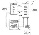
- Figure 7is a block diagram 83 showing a logical implementation of device 40.
- Logical block 84receives process signals and calculates statistical parameters for the process signals.
- Block 84provides a statistical parameter output 88 of the raw process signal and a statistical parameter output 90 of the preprocessed process signal as discussed above.
- These statistical parametersinclude, for example, standard deviation, mean, sample variance, root-mean-square (RMS), range ( ⁇ R), rate of change (ROC) and skewness of the process signal.
- x MAX and x MINare the respective maximum and minimum of the process signal over a sampling or training time period. These statistical parameters are calculated alone or in any combination. It will be understood that the invention includes any statistical parameter including those which are explicitly set forth herein.
- the calculate statistical parametersare received by rule calculation logic block 86 which operates in accordance with rules 80 stored in memory 48. Block 86 provides a diagnostic module. Block 86 compares parameters 88 and 90 in accordance with rules 80 and sensitivity parameters 82. Rules block 86 may also receive optional trained values 78 from memory 48.
- trained valuesare the nominal or (i.e., typical) statistical parameter value for the raw and/or preprocessed process signal and comprise the same statistical parameters (standard deviation, mean, sample variance, root-mean-square (RMS), range and rate of change, etc.) used in logical block 84.
- the trained valuescan be provided by the manufacturer, periodically updated by addressing device 40 over loop 6 or can be learned during normal operation of the process.
- Rule calculation block 86receives sensitivity parameters 82 from memory 48 along with statistical parameters 88 and 90.
- Block 86provides examples of a number of different rules.
- Each sensitivity parameter 82provides an acceptable range or relationship as determined by the appropriate rule 80 between the statistical parameter of the raw data 88 and the statistical parameter of the preprocessed data 90. Since the sensitivity parameter 82 may be set by the manufacturer, received over loop 6 or input using input circuitry 76, the sensitivity parameters can be adjusted for a specific application. For example, in process control applications where high accuracy is required, the sensitivity parameters are set so as to allow only small variations of the process signals relative to the statistical parameters of the preprocessed process signals.
- sensitivity parametersallows the diagnostic and event detection decision making performed by diagnostic circuitry 86 to be controlled based upon the particular process and the requirements of the user.
- the particular diagnostic outputis determined based upon the application, data and rules. Examples include identification of a spike, drift, bias, noise, stuck or cyclic condition in the process. It is appreciated that the diagnostic output may be related to the industrial process itself or to the field devices such as transmitters and controllers that are used to monitor and/or control the industrial process.
- a specific filteris provided as discussed below. This specific filter is applicable to any configuration and is not limited to the particular architectures set forth herein.
- a filteris provided to improve intermediate and long term variation in a given signal and further to isolate short term variation.
- the short term variation in the signalis sometimes referred to as the "process noise.”
- One standard technique of isolating the process noise of a signalis to implement a digital high pass filter in software.
- the filtercan comprise a type of IIR or a type of FIR.
- Such filterscan be designed to match a certain frequency response criteria to a desired filter transfer function.
- one type of existing filteris used to identify a plugged line -condition and uses a 16 th order FIR filter using the transfer function set forth in Equation 8.
- a filter configurationis illustrated in Figure 8 .
- frequencyis normalized so that one is equal to one half of the sampling rate which is 11 Hz. Therefore, the filter illustrated in Figure 8 will stop all parts of the signal from DC to about 1.1 Hz, and pass the parts from 3 . 3 Hz to 11 Hz.
- the transition bandis from 1.1 Hz to 3.3 Hz.
- the primary purpose of such a filteris to remove transients from the signal so that other statistical parameters, such as standard deviation of flow noise, can be calculated.
- the filter of the present inventioncan be preapplied to the measurement sequence to evaluate the short term variation in the signal.
- the filtercan be implemented as a first order filter and require only one subtraction per measurement point, compared to 17 multiplications and 16 additions for the 16 th order FIR filter discussed above.
- the filter of the present inventioncan remove trends and transients and isolate process noise.
- the filteris implemented as a difference filter.
- Figure 9is a graph of magnitude versus frequency for such a filter.
- the filtercontinuously promotes higher frequency values and similarly continuously demotes lower frequency values.
- the filter of Equation 9provides desirable response for all trends in the signal.
- Figure 10is a graph of a pressure signal which includes a signal trend along with some pressure noise.
- Figure 11is a graph of difference versus time.
- the difference filteris well suited for providing the process noise signal for use in subsequent diagnostics.
- the pass band gain of the filtercan be scaled to match engineering units or other criteria as desired.
- process variablemeans any variable which describes the condition of the process such as, for example, pressure, flow, temperature, product level, pH, turbidity, vibration, position, motor current, any other characteristic of the process, etc.
- Control signalmeans any signal (other than a process variable) which is used to control the process.
- control signalmeans a desired process variable value (i.e. a setpoint) such as a desired temperature, pressure, flow, product level, pH or turbidity, etc., which is adjusted by a controller or used to control the process.
- a control signalmeans, calibration values, alarms, alarm conditions, the signal which is provided to a control element such as a valve position signal which is provided to a valve actuator, an energy level which is provided to a heating element, a solenoid on/off signal, etc., or any other signal which relates to control of the process.
- a diagnostic signal as used hereinincludes information related to operation of devices and elements in the process control loop, but does not include process variables or control signals.
- diagnostic signalsinclude valve stem position, applied torque or force, actuator pressure, pressure of a pressurized gas used to actuate a valve, electrical voltage, current, power, resistance, capacitance, inductance, device temperature, stiction, friction, full on and off positions, travel, frequency, amplitude, spectrum and spectral components, stiffness, electric or magnetic field strength, duration, intensity, motion, electric motor back emf, motor current, loop related parameters (such as control loop resistance, voltage, or current) , or any other parameter which may be detected or measured in the system.
- process signalmeans any signal which is related to the process or element in the process such as, for example, a process variable, a control signal or a diagnostic signal.
- Process devicesinclude any device which forms part of or couples to a process control loop and is used in the control or monitoring of a process.
- the various functional blocks and circuitry described hereincan be implemented in digital or analog circuitry. Various functional blocks and circuitry may share components and may be partially or wholly implemented in the same circuit. For example, digital processing circuitry can be employed to implement numerous functions based upon programming instructions stored in memory.
- the rules block 86provides one example diagnostic module configured to diagnose operation of the industrial process based upon first and second statistical parameters, however, the present invention may be used with other diagnostic modules and is not limited the diagnostic module discussed herein.
- diagnosing operation of an industrial process controller monitoring systemincludes diagnosing operation of the industrial process external to a field device as well as internal to the field device.
- the diagnosingcan include identifying the occurrence of a degrading element or a plugged line within a process device, or used to couple a process device to the industrial process.
- Custom filterscan be updated in the field using parameters received over any appropriate technique.
- the present inventionis applicable to other configurations including multivariable applications.
- a field devicecan include multiple sensors in which all of the data processing discussed above are performed on the multiple measurement data streams.
- a field device that includes a single sensoralso receives process data from other field devices for use in making and performing diagnostics on multiple measurements.
Landscapes
- Engineering & Computer Science (AREA)
- Physics & Mathematics (AREA)
- Chemical & Material Sciences (AREA)
- Automation & Control Theory (AREA)
- Oil, Petroleum & Natural Gas (AREA)
- General Physics & Mathematics (AREA)
- General Chemical & Material Sciences (AREA)
- Organic Chemistry (AREA)
- Chemical Kinetics & Catalysis (AREA)
- Artificial Intelligence (AREA)
- Evolutionary Computation (AREA)
- Mathematical Physics (AREA)
- Testing And Monitoring For Control Systems (AREA)
- Vaporization, Distillation, Condensation, Sublimation, And Cold Traps (AREA)
Abstract
Description
- The present invention relates to industrial process control and monitoring systems. More specifically, the present invention relates to diagnostic and such systems.
- Process control loops are used in industry to control operation of a process, such as an oil refinery. A transmitter is typically part of the loop and is located in the field to measure and transmit a process variable such as pressure, flow or temperature, for example, to control room equipment. A controller such as a valve controller is also part of the process control loop and controls position of a valve based upon a control signal received over the control loop or generated internally. Other controllers control electric motors or solenoids for example. The control room equipment is also part of the process control loop such that an operator or computer in the control room is capable of monitoring the process based upon process variables received from transmitters in the field and responsively controlling the process by sending control signals to the appropriate control devices. Another process device which may be part of a control loop is a portable communicator which is capable of monitoring and transmitting process signals on the process control loop. Typically, these are used to configure devices which form the loop.
US2002/0029130 describes a flow diagnostic system in which multiple algorithms are used sequentially to calculate a diagnostic output.US 6,532,392 describes a transmitter and process device which calculate statistical parameters for process signals to determine when to initiate diagnostics.- There is an ongoing desire to perform diagnostics on such industrial control and monitoring systems. Preferably, such diagnostics identify the possibility that a component will fail prior to its ultimate failure such that preventive maintenance can be performed.
- The present invention provides a device and method for diagnosing operation of an industrial process, as set out in
claims 1 and 21 respectively. - A device for diagnosing operation of an industrial process control or monitoring system includes an input configured to receive an input related to a process signal. A first statistical parameter module configured provides a first statistical parameter output related to a statistical parameter of the process signal. A filter provides a filter output related to a filtered value of the process signal. A second statistical parameter module provides a second statistical parameter output related to a statistical parameter of the filter output. A diagnostic module diagnoses operation of the industrial process based upon the first and second statistical parameters. An example of a specific filter implementation based upon a difference filter is also provided.
Figure 1 is a diagram of an industrial process control or monitoring system for use with the present invention.Figure 2 is a simplified diagram of a statistical parameter module.Figure 3 is a simplified diagram of a module including two statistical parameter modules and a filter.Figure 4 is a block diagram showing the filter ofFigure 3 .Figure 5 is a block diagram showing the filter ofFigure 4 .Figure 6 is a block diagram showing a process device ofFigure 1 in more detail.Figure 7 is a logical block diagram showing operation of a device for diagnosing operation of the process control or monitoring system ofFigure 1 .Figure 8 is a graph of the frequency response which illustrates normalized magnitude versus frequency for an FIR filter.Figure 9 is a graph of magnitude versus frequency for a difference filter.Figure 10 is a graph of a process pressure signal including a trend along with process noise.Figure 11 is a graph of a difference versus time showing the filtered output based upon the input signal illustrated inFigure 10 .- As discussed in the Background section, there is an ongoing need to perform diagnostics in industrial control and monitoring systems. Some pioneering work in this area is described
U.S. Patent Nos. 6,449,574 ;6,772,036 ;6,047,220 ;5,746,511 :5,828,567 ;5,665,899 ;6,017,143 ;6,119,047 ;5,956,663 ;6,370,448 ;6,519,546 ;6,594,603 ;6,556,145 ;6,356,191 ;6,601,005 ;6,397,114 ;6,505,517 ;6,701,274 ;6,754,601 ;6,434,504 ;6,654,697 ;6,539,267 ;6,532,392 ;6,611,775 ;6,615,149 ;6,907,383 ;6,629,059 ;6,859,755 ; and6,889,x66 - The present invention includes the recognition that certain diagnostic applications require signal filtering in order to provide improved diagnostics. A modular filtering architecture is provided along with filter algorithms.
Figure 1 is a diagram showing an example of a process control system 2 which includes process piping 4 which carries a process fluid and two wire process control loop 6 carrying loop currentI. A transmitter 8,controller 10, which couples to a final control element in the loop such as an actuator, valve, a pump, motor or solenoid,communicator 12, andcontrol room 14 are all part of process control loop 6. It is understood that loop 6 is shown in one configuration and any appropriate process control loop may be used such as a 4-20 mA loop, 2, 3 or 4 wire loop, multidrop loop and a loop operating in accordance with the HART(R), Foundation Fieldbus(TM) or other digital or analog communication protocol including wireless techniques. In operation,transmitter 8 senses a process variable such asflow using sensor 16 and transmits the sensed process variable over loop 6. The process variable may be received by controller/valve actuator 10,communicator 12 and/orcontrol room equipment 14.Controller 10 is shown coupled tovalve 18 and is capable of controlling the process by adjustingvalve 18 thereby changing the flow in pipe 4.Controller 10 receives a control input over loop 6 from, for example,control room 14,transmitter 8 orcommunicator 12 and responsively adjustsvalve 18. In another configuration,controller 10 internally generates the control signal based upon process signals received over loop 6.Communicator 12 may be the portable communicator shown inFigure 1 or may be a permanently mounted process unit which monitors the process and performs computations. Process devices include, for example, transmitter 8 (such as a 3051S transmitter available from Rosemount Inc.),controller 10,communicator 12 andcontrol room 14 shown inFigure 1 . Another type of process device is a PC, programmable logic unit (PLC) or other computer coupled to the loop using appropriate I/O circuitry to allow monitoring, managing, and/or transmitting on the loop.- In one aspect, the present invention provides a group of techniques for processing field data through various statistical and digital signal processing algorithms and providing the processed data for use in subsequent diagnostic operations. For example, the processed data can be used for diagnostics to provide alarms and warnings to field devices and host systems. The techniques can be used with any type of process control loop. It is not limited to the loops described herein such as those operations in accordance with HART®, Foundation Fieldbus™, Profibus, or other protocols.
- Performing statistical and digital signal processing within a field device provides the capability to operate on the raw data measurement before any measurements and control related modifications are made to the sensor data. Therefore, the signatures computed within the device are better indicators of the conditions of the system such as the mechanical equipment in the process in which the device is installed. Typically, the communications systems used in industrial process control or monitoring systems do not operate at sufficient speed to provide raw data on a plant-wide basis. In other words, typically all of the raw data collected in a process control or monitoring system cannot be transmitted to other field devices or to a control room due to bandwidth limitations of the communication protocols. Further, even if such transmission is possible, loading the network (process control loop) with excessive raw data transfers can adversely affect the other tasks which rely on the network for measurement and control.
- The present invention utilizes a basic statistical
processing building block 100 which is illustrated inFig. 2. Fig. 2 is a block diagram showing thestatistical parameter module 100 which can provide any number of statistical functions. In the embodiment ofFig. 2 , thestatistical parameter module 100 receives an input data stream which can comprise, for example, the digitized data from a process variable sensor. Thestatistical parameter module 100 provides one or more statistical parameters of the input data. For example, thestatistical parameter module 100 can provide minimum or maximum values, a range, a mean of the data, RMS (root mean squared) value of the data and/or a standard deviation of the data. As used herein, "statistical parameter" includes any statistical parameter of the data including minimum, maximum, range, mean, RMS, standard deviation, Q25, Q50, Q.75, and others. Figure 3 is a block diagram showing an enhancedstatistical parameter module 102 which includesstatistical parameter module 100 illustrated inFigure 2 .Module 102 receives raw data and provides at least two data paths therethrough. One data path provides the raw data directly to astatistical parameter module 100 which provides an output related to a statistical parameter of the raw data. A second data path provides the raw data to apreprocessing block 104. Preprocessing block 104 can apply a filter or trimming process to the raw data stream. The preprocesseddata 106 is provided to a secondstatistical parameter module 100 which provides an output related to a statistical parameter of the preprocessed raw data. The preprocessing can be performed as desired. One example of a preprocess includes the trimming of the raw data which can be used to eliminate spikes, outliers in the data or other bad data points so they do not skew the statistical parameter determined by thestatistical parameter module 100. The trimming can be in accordance with any appropriate technique including techniques which are based upon sorting and removal of certain data points such as data points falling outside of upper and lower percentages of the data, as well as using thresholds based upon standard deviation, a weighted moving average, etc.. The trimmed data may be removed from the data sequence. In another example, the trimmed data can be replaced using interpolation techniques.Figure 4 is a block diagram of the filter and trimsignal preprocessing block 104.Block 104 provides a highly configurable filter in which the raw data input can be provided to a customizedfilter 120 or through astandard filter 122. Customized filter includes optional prefilter blocks 124 and/or postfilter trimming blocks 124 to trim the data stream as discussed above, along with a customizedfilter 126 selected as desired.Standard filter 122 also includes optional pre and post trimming block 124 along with astandardized filter block 126.Standard 126 can include a number of different selectable standardized filters which can be selected as desired. In the example ofFigure 5 , thestandardized filter 126 includes four filters (no filter, low pass filter, high pass filter, and band pass filter) which can be selected as desired along with an off position.- In the above discussion, the filters and trimming functions can be implemented in digital circuitry, for example in a digital signal processor or a microprocessor. Using the configuration set forth in
Figure 3 , a highly configurable diagnostic system can be implemented. In one embodiment, a statistical parameter of the raw data stream is compared to a statistical parameter of the preprocessed data stream. If the comparison falls outside off an acceptable range, a diagnostic output condition can be provided which indicates a diagnostic condition of the process control system. - Any of the
process devices Figure 1 may include diagnostic circuitry in accordance with the present invention.Figure 6 is a block diagram of aprocess device 40 forming part of loop 6.Device 40 is shown generically and may comprise any process device such astransmitter 8,controller 10,communicator 12 orcontrol room equipment 14.Control room equipment 14 may comprise, for example, a DCS system implemented with a PLC andcontroller 10 may also comprise a "smart" motor and pump.Process device 40 includes I/O circuitry coupled to loop 6 atterminals 44. I/O circuitry has preselected input and output impedance known in the art to facilitate appropriate communication from and todevice 40.Device 40 includesmicroprocessor 46, coupled to I/O circuitry 42,memory 48 coupled tomicroprocessor 46 andclock 50 coupled tomicroprocessor 46.Microprocessor 46 receives aprocess signal input 52. Block input is intended to signify input of any process signal, and as explained above, the process signal input may be a process variable, or a control signal and may be received from loop 6 using I/O circuitry 42 or may be generated internally withinfield device 40.Field device 40 is shown with asensor input channel 54 and acontrol channels 56. Typically, a transmitter (such as transmitter 8) will exclusively includesensor input channel 54 while a controller such ascontroller 10 will exclusively include acontrol channel 56. Other devices on loop 6 such ascommunicator 12 andcontrol room equipment 14 may not includechannels device 40 may contain a plurality of channels to monitor a plurality of process variables and/or control a plurality of control elements as appropriate. Sensor input channel 54 includessensor 16, sensing a process variable and providing a sensor output to amplifier 58 which has an output which is digitized by analog todigital converter 60.Channel 54 is typically used in transmitters such astransmitter 8.Compensation circuitry 62 compensates the digitized signal and provides a digitized process variable signal tomicroprocessor 46. In one embodiment,channel 54 comprises a diagnostic channel which receives a diagnostic signal.- When
process device 40 operates as a controller such ascontroller 8,device 40 includescontrol channel 56 havingcontrol element 18 such as a valve, for example.Control element 18 is coupled tomicroprocessor 46 through digital toanalog converter 64,amplifier 66 andactuator 68. Digital toanalog converter 64 digitizes a command output frommicroprocessor 46 which is amplified byamplifier 66.Actuator 68 controls thecontrol element 18 based upon the output fromamplifier 66. In one embodiment,actuator 68 is coupled directly to loop 6 and controls a source of pressurized gas (not shown) to position controlelement 18 in response to the current I flowing through loop 6. In one embodiment,controller 10 includescontrol channel 56 to control a control element and also includessensor input channel 54 which provides a diagnostic signal such as valve stem position, force, torque, actuator pressure, pressure of a source of pressurized air, etc. - In one embodiment, I/
O circuitry 42 provides a power output used to completely power other circuitry inprocess device 40 using power received from loop 6. Typically, field devices such astransmitter 8, orcontroller 10 are powered off the loop 6 whilecommunicator 12 orcontrol room 14 has a separate power source. As described above,process signal input 52 provides a process signal tomicroprocessor 46. The process signal may be a process variable fromsensor 16, the control output provided to controlelement 18, a diagnostic signal sensed bysensor 16, or a control signal, process variable or diagnostic signal received over loop 6, or a process signal received or generated by some other means such as another I/O channel. - A user I/O circuit 76 is also connected to
microprocessor 46 and provides communication betweendevice 40 and a user. Typically, user I/O circuit 76 includes a display and audio for output and a keypad for input. Typically,communicator 12 andcontrol room 14 includes I/O circuit 76 which allows a user to monitor and input process signals such as process variables, control signals (setpoints, calibration values, alarms, alarm conditions, etc.). A user may also use circuit 76 incommunicator 12 orcontrol room 14 to send and receive such process signals totransmitter 8 andcontroller 10 over loop 6. Further, such circuitry could be directly implemented intransmitter 8,controller 10 or anyother process device 40. Microprocessor 46 acts in accordance with instructions stored inmemory 48.Memory 48 also contains optional trainedvalues 78,rules 80 andsensitivity parameters 82. The combination of thesensitivity parameters 82 and the trainedvalues 78 provide anominal value 79.Figure 7 is a block diagram 83 showing a logical implementation ofdevice 40.Logical block 84 receives process signals and calculates statistical parameters for the process signals.Block 84 provides astatistical parameter output 88 of the raw process signal and astatistical parameter output 90 of the preprocessed process signal as discussed above. These statistical parameters include, for example, standard deviation, mean, sample variance, root-mean-square (RMS), range (ΔR), rate of change (ROC) and skewness of the process signal. These can be determined using the following equations:


Where N is the total number of data points in the sample period, xi and xi-1 are two consecutive values of the process signal and T is the time interval between the two values. Further, xMAX and xMIN are the respective maximum and minimum of the process signal over a sampling or training time period. These statistical parameters are calculated alone or in any combination. It will be understood that the invention includes any statistical parameter including those which are explicitly set forth herein. The calculate statistical parameters are received by rulecalculation logic block 86 which operates in accordance withrules 80 stored inmemory 48.Block 86 provides a diagnostic module.Block 86 comparesparameters rules 80 andsensitivity parameters 82. Rules block 86 may also receive optional trainedvalues 78 frommemory 48. If implemented, trained values are the nominal or (i.e., typical) statistical parameter value for the raw and/or preprocessed process signal and comprise the same statistical parameters (standard deviation, mean, sample variance, root-mean-square (RMS), range and rate of change, etc.) used inlogical block 84. The trained values can be provided by the manufacturer, periodically updated by addressingdevice 40 over loop 6 or can be learned during normal operation of the process.Rule calculation block 86 receivessensitivity parameters 82 frommemory 48 along withstatistical parameters Block 86 provides examples of a number of different rules. Eachsensitivity parameter 82 provides an acceptable range or relationship as determined by theappropriate rule 80 between the statistical parameter of theraw data 88 and the statistical parameter of the preprocesseddata 90. Since thesensitivity parameter 82 may be set by the manufacturer, received over loop 6 or input using input circuitry 76, the sensitivity parameters can be adjusted for a specific application. For example, in process control applications where high accuracy is required, the sensitivity parameters are set so as to allow only small variations of the process signals relative to the statistical parameters of the preprocessed process signals. The use of sensitivity parameters allows the diagnostic and event detection decision making performed bydiagnostic circuitry 86 to be controlled based upon the particular process and the requirements of the user. The particular diagnostic output is determined based upon the application, data and rules. Examples include identification of a spike, drift, bias, noise, stuck or cyclic condition in the process. It is appreciated that the diagnostic output may be related to the industrial process itself or to the field devices such as transmitters and controllers that are used to monitor and/or control the industrial process.- Although the various functions set forth herein can be implemented using any appropriate filter, in one configuration, a specific filter is provided as discussed below. This specific filter is applicable to any configuration and is not limited to the particular architectures set forth herein. In one configuration, a filter is provided to improve intermediate and long term variation in a given signal and further to isolate short term variation. The short term variation in the signal is sometimes referred to as the "process noise." One standard technique of isolating the process noise of a signal is to implement a digital high pass filter in software. The filter can comprise a type of IIR or a type of FIR. A typical FIR filter of order n can be implemented as follows:

where y is the filtered value, x are the current and previous measurements and xt-i are the current/previous measurements and ai are the filter coefficients. Such filters can be designed to match a certain frequency response criteria to a desired filter transfer function. - For example, one type of existing filter is used to identify a plugged line -condition and uses a 16th order FIR filter using the transfer function set forth in
Equation 8. In such a filter configuration is illustrated inFigure 8 . InFigure 8 , frequency is normalized so that one is equal to one half of the sampling rate which is 11 Hz. Therefore, the filter illustrated inFigure 8 will stop all parts of the signal from DC to about 1.1 Hz, and pass the parts from 3 . 3 Hz to 11 Hz. The transition band is from 1.1 Hz to 3.3 Hz. The primary purpose of such a filter is to remove transients from the signal so that other statistical parameters, such as standard deviation of flow noise, can be calculated. However, such a filter cannot guarantee that all transients will be removed since some transients will have components which are higher frequencies. Further, the transition band cannot be moved much higher because this could filter some process noise along with the transients. In other words, the filter will either pass some transients or filter out some flow noise. In addition, since the DC gain will not be zero, the mean of the filtered signal will not reach zero and will carry and offset value. This also is not desirable. - The filter of the present invention can be preapplied to the measurement sequence to evaluate the short term variation in the signal. The filter can be implemented as a first order filter and require only one subtraction per measurement point, compared to 17 multiplications and 16 additions for the 16th order FIR filter discussed above. The filter of the present invention can remove trends and transients and isolate process noise. The filter is implemented as a difference filter. A first order difference filter is defined as:

where y is the output signal and xt is the current value of the input signal andXt-1 is the previous value of the input signal.Figure 9 is a graph of magnitude versus frequency for such a filter. The filter continuously promotes higher frequency values and similarly continuously demotes lower frequency values. As the frequency content of the trends and transients in a typical process signal is not known, the filter of Equation 9 provides desirable response for all trends in the signal.Figure 10 is a graph of a pressure signal which includes a signal trend along with some pressure noise. When the filter of Equation 9 is applied to the signal ofFigure 10 , the resultant signal is illustrated inFigure 11 which is a graph of difference versus time. As illustrated inFigure 11 , the difference filter is well suited for providing the process noise signal for use in subsequent diagnostics. The pass band gain of the filter can be scaled to match engineering units or other criteria as desired. - As used herein, process variable means any variable which describes the condition of the process such as, for example, pressure, flow, temperature, product level, pH, turbidity, vibration, position, motor current, any other characteristic of the process, etc. Control signal means any signal (other than a process variable) which is used to control the process. For example, control signal means a desired process variable value (i.e. a setpoint) such as a desired temperature, pressure, flow, product level, pH or turbidity, etc., which is adjusted by a controller or used to control the process. Additionally, a control signal means, calibration values, alarms, alarm conditions, the signal which is provided to a control element such as a valve position signal which is provided to a valve actuator, an energy level which is provided to a heating element, a solenoid on/off signal, etc., or any other signal which relates to control of the process. A diagnostic signal as used herein includes information related to operation of devices and elements in the process control loop, but does not include process variables or control signals. For example, diagnostic signals include valve stem position, applied torque or force, actuator pressure, pressure of a pressurized gas used to actuate a valve, electrical voltage, current, power, resistance, capacitance, inductance, device temperature, stiction, friction, full on and off positions, travel, frequency, amplitude, spectrum and spectral components, stiffness, electric or magnetic field strength, duration, intensity, motion, electric motor back emf, motor current, loop related parameters (such as control loop resistance, voltage, or current) , or any other parameter which may be detected or measured in the system. Furthermore, process signal means any signal which is related to the process or element in the process such as, for example, a process variable, a control signal or a diagnostic signal. Process devices include any device which forms part of or couples to a process control loop and is used in the control or monitoring of a process.
- Although the present invention has been described with reference to preferred embodiments, workers skilled in the art will recognize that changes may be made in form and detail without departing from the scope of the invention as defined by the appended claims. The various functional blocks and circuitry described herein can be implemented in digital or analog circuitry. Various functional blocks and circuitry may share components and may be partially or wholly implemented in the same circuit. For example, digital processing circuitry can be employed to implement numerous functions based upon programming instructions stored in memory. The rules block 86 provides one example diagnostic module configured to diagnose operation of the industrial process based upon first and second statistical parameters, however, the present invention may be used with other diagnostic modules and is not limited the diagnostic module discussed herein. As used herein, diagnosing operation of an industrial process controller monitoring system includes diagnosing operation of the industrial process external to a field device as well as internal to the field device. For example, the diagnosing can include identifying the occurrence of a degrading element or a plugged line within a process device, or used to couple a process device to the industrial process. Custom filters can be updated in the field using parameters received over any appropriate technique. The present invention is applicable to other configurations including multivariable applications. For example, a field device can include multiple sensors in which all of the data processing discussed above are performed on the multiple measurement data streams. In another example configuration, a field device that includes a single sensor also receives process data from other field devices for use in making and performing diagnostics on multiple measurements.


Claims (29)
- A device for diagnosing operation of an industrial process control or monitoring system, comprising:an input configured to receive input data related to a process signal;a first statistical parameter module (100) configured to provide a first statistical parameter output (88) related to a statistical parameter of the input data;a filter (104) configured to provide a filter output related to a filtered value of the input data;a second statistical parameter module (100) configured to provide a second statistical parameter output (90) related to a statistical parameter of the filter output; anda diagnostic module (86) configured to diagnose operation of an industrial process based upon a comparison of the first (88) and the second (90) statistical parameters outputs,characterised in that the device comprises at least two data paths therethrough, the first statistical parameter module disposed on the first data path, and the second statistical parameter module and filter disposed on the second path;the input is configured to provide the received input data to the first statistical parameter module via the first data path, and to provide the same received input data to the filter via the second data path.
- The apparatus of claim 1 wherein the filter (104) is configured to reduce the number of data points in the input data.
- The apparatus of claim 2 wherein the filter (104) is configured to remove numerically distant data points in the data.
- The apparatus of claim 2 wherein the filter (104) is configured to remove data based upon a comparison of the data with a moving average.
- The apparatus of claim 2 wherein the filter (104) is configured to remove data spikes in the data.
- The apparatus of claim 1 wherein the first and second statistical parameters are selected from the group of statistical parameters consisting of minimum, maximum, range, mean, root mean squared and standard deviation.
- The apparatus of claim 1 wherein the filter (104) comprises a low pass filter.
- The apparatus of claim 1 wherein the filter (104) comprises a band pass filter.
- The apparatus of claim 1 wherein the filter (104) comprises a high pass filter.
- The apparatus of claim 1 wherein the filter (104) comprises a custom filter.
- The apparatus of claim 10 wherein the custom filter is based upon a received parameter.
- The apparatus of claim 1 including a second input configured to receive a second input related to a second process signal and wherein the diagnostic module diagnoses operation of the industrial process further based upon the second process signal.
- The apparatus of claim 1 wherein the diagnostic module is configured to diagnose operation of the industrial process based upon a relationship between the first statistical parameter and the second statistical parameter provided in a rule.
- The apparatus of claim 1 wherein the diagnostic module is configured to diagnose operation of the industrial process based upon a sensitivity parameter which provides an acceptable range between the first and second statistical parameter values.
- The apparatus of claim 1 including an input/output connection coupled to a process control loop.
- The apparatus of claim 15 wherein power for the device is received from a process control loop.
- The apparatus of claim 1 including a sensor configured to provide an output related to a sensed process variable on a two-wire process control loop.
- The apparatus of claim 1 including a control element configured to control a process variable and input configured to receive a control signal from a two-wire process control loop.
- The apparatus of claim 1 wherein the filter includes a plurality of selectable filter functions
- The apparatus of claim 1 wherein the filter comprises a difference filter.
- A method for diagnosing operation of an industrial process or monitoring system, comprising:receiving input data related to a process signal;calculating a first statistical parameter related to a statistical parameter of the input data;filtering the input data using a filter to provide a filtered value of the input data;calculating a second statistical parameter (90) based upon the filtered value; anddiagnosing operation of an industrial process based upon a comparison of the first statistical parameter (88) and the second statistical parameter (90),characterised in that the statistical parameters are provided on at least two data paths such that the first statistical parameter is provided on a first data path, and the second statistical parameter and the filter are provided on a second data path; andthe received input data is provided to the first data path and the same received input data is provided to the second data path.
- The method of claim 21 wherein the filter (104) is configured to reduce the number of data points in the input data.
- The method of claim 22 wherein the filter (104) is configured to remove numerically distant data points in the data.
- The method of claim 22 wherein the filter (104) is configured to remove data based upon a comparison of the data with a moving average.
- The method of claim 22 wherein the filter (104) is configured to remove data spikes in the data.
- The method of claim 21 wherein the first (88) and second (90) statistical parameters are selected from the group of statistical parameters consisting of minimum, maximum, range, mean, root mean squared and standard deviation.
- The method of claim 21 wherein the filter (104) is selected from the group of filters consisting of low pass, high pass and band pass filter.
- The method of claim 21 including selecting a filter function in a filter module which includes a plurality of filter functions.
- The method of claim 20 wherein filtering comprises applying a difference filter.
Applications Claiming Priority (2)
| Application Number | Priority Date | Filing Date | Title |
|---|---|---|---|
| US66824305P | 2005-04-04 | 2005-04-04 | |
| PCT/US2006/012472WO2006107952A1 (en) | 2005-04-04 | 2006-04-04 | Diagnostics in industrial process control system |
Publications (2)
| Publication Number | Publication Date |
|---|---|
| EP1866716A1 EP1866716A1 (en) | 2007-12-19 |
| EP1866716B1true EP1866716B1 (en) | 2011-06-29 |
Family
ID=36693113
Family Applications (2)
| Application Number | Title | Priority Date | Filing Date |
|---|---|---|---|
| EP06749231ACeasedEP1866716B1 (en) | 2005-04-04 | 2006-04-04 | Diagnostics in industrial process control system |
| EP06749217ANot-in-forceEP1872184B1 (en) | 2005-04-04 | 2006-04-04 | Statistical processing method for detection of abnormal situations |
Family Applications After (1)
| Application Number | Title | Priority Date | Filing Date |
|---|---|---|---|
| EP06749217ANot-in-forceEP1872184B1 (en) | 2005-04-04 | 2006-04-04 | Statistical processing method for detection of abnormal situations |
Country Status (9)
| Country | Link |
|---|---|
| US (4) | US7752012B2 (en) |
| EP (2) | EP1866716B1 (en) |
| JP (2) | JP5049956B2 (en) |
| CN (4) | CN103777628B (en) |
| AT (1) | ATE511128T1 (en) |
| BR (1) | BRPI0610522A2 (en) |
| CA (1) | CA2603916A1 (en) |
| RU (1) | RU2007137820A (en) |
| WO (2) | WO2006107952A1 (en) |
Cited By (1)
| Publication number | Priority date | Publication date | Assignee | Title |
|---|---|---|---|---|
| CN103760772A (en)* | 2014-01-22 | 2014-04-30 | 杭州电子科技大学 | Batch process PI-PD control method for state space prediction function control optimization |
Families Citing this family (141)
| Publication number | Priority date | Publication date | Assignee | Title |
|---|---|---|---|---|
| US20020191102A1 (en)* | 2001-05-31 | 2002-12-19 | Casio Computer Co., Ltd. | Light emitting device, camera with light emitting device, and image pickup method |
| JP5049956B2 (en) | 2005-04-04 | 2012-10-17 | フィッシャー−ローズマウント システムズ,インコーポレイテッド | Statistical processing methods used to detect abnormal situations |
| US8612802B1 (en) | 2011-01-31 | 2013-12-17 | Open Invention Network, Llc | System and method for statistical application-agnostic fault detection |
| US8719327B2 (en)* | 2005-10-25 | 2014-05-06 | Fisher-Rosemount Systems, Inc. | Wireless communication of process measurements |
| US7643428B1 (en)* | 2005-11-09 | 2010-01-05 | Embarq Holdings Company, Llc | Early detection of faulty communications links |
| US7894473B2 (en)* | 2006-04-12 | 2011-02-22 | Honeywell International Inc. | System and method for monitoring valve status and performance in a process control system |
| US8145358B2 (en) | 2006-07-25 | 2012-03-27 | Fisher-Rosemount Systems, Inc. | Method and system for detecting abnormal operation of a level regulatory control loop |
| US7912676B2 (en) | 2006-07-25 | 2011-03-22 | Fisher-Rosemount Systems, Inc. | Method and system for detecting abnormal operation in a process plant |
| US8606544B2 (en) | 2006-07-25 | 2013-12-10 | Fisher-Rosemount Systems, Inc. | Methods and systems for detecting deviation of a process variable from expected values |
| US7657399B2 (en)* | 2006-07-25 | 2010-02-02 | Fisher-Rosemount Systems, Inc. | Methods and systems for detecting deviation of a process variable from expected values |
| CN102789226B (en) | 2006-09-28 | 2015-07-01 | 费舍-柔斯芒特系统股份有限公司 | Abnormal situation prevention in a heat exchanger |
| US20080116051A1 (en)* | 2006-09-29 | 2008-05-22 | Fisher-Rosemount Systems, Inc. | Main column bottoms coking detection in a fluid catalytic cracker for use in abnormal situation prevention |
| US20080120060A1 (en)* | 2006-09-29 | 2008-05-22 | Fisher-Rosemount Systems, Inc. | Detection of catalyst losses in a fluid catalytic cracker for use in abnormal situation prevention |
| US8032340B2 (en) | 2007-01-04 | 2011-10-04 | Fisher-Rosemount Systems, Inc. | Method and system for modeling a process variable in a process plant |
| US8032341B2 (en)* | 2007-01-04 | 2011-10-04 | Fisher-Rosemount Systems, Inc. | Modeling a process using a composite model comprising a plurality of regression models |
| US7827006B2 (en) | 2007-01-31 | 2010-11-02 | Fisher-Rosemount Systems, Inc. | Heat exchanger fouling detection |
| RU2331098C1 (en)* | 2007-05-28 | 2008-08-10 | ОБЩЕСТВО С ОГРАНИЧЕННОЙ ОТВЕТСТВЕННОСТЬЮ "СКУ Система" (ООО "СКУ Система") | Parameter control device |
| EP2176470B1 (en) | 2007-07-20 | 2021-01-13 | Rosemount Inc. | Differential pressure diagnostic for process fluid pulsations |
| US7770459B2 (en)* | 2007-07-20 | 2010-08-10 | Rosemount Inc. | Differential pressure diagnostic for process fluid pulsations |
| US8898036B2 (en) | 2007-08-06 | 2014-11-25 | Rosemount Inc. | Process variable transmitter with acceleration sensor |
| DE102007038060A1 (en)* | 2007-08-10 | 2009-02-12 | Endress + Hauser Wetzer Gmbh + Co. Kg | Device for determining and / or monitoring a process variable |
| US8301676B2 (en)* | 2007-08-23 | 2012-10-30 | Fisher-Rosemount Systems, Inc. | Field device with capability of calculating digital filter coefficients |
| US7702401B2 (en) | 2007-09-05 | 2010-04-20 | Fisher-Rosemount Systems, Inc. | System for preserving and displaying process control data associated with an abnormal situation |
| US8428909B2 (en)* | 2007-09-20 | 2013-04-23 | Siemens Industry, Inc. | Use of statistics to determine calibration of instruments |
| US7590511B2 (en)* | 2007-09-25 | 2009-09-15 | Rosemount Inc. | Field device for digital process control loop diagnostics |
| US20090093893A1 (en)* | 2007-10-05 | 2009-04-09 | Fisher-Rosemount Systems, Inc. | System and method for recognizing and compensating for invalid regression model applied to abnormal situation prevention |
| US8055479B2 (en) | 2007-10-10 | 2011-11-08 | Fisher-Rosemount Systems, Inc. | Simplified algorithm for abnormal situation prevention in load following applications including plugged line diagnostics in a dynamic process |
| WO2009070703A1 (en)* | 2007-11-29 | 2009-06-04 | Rosemount, Inc. | Process fluid pressure transmitter with pressure transient detection |
| US7693606B2 (en)* | 2007-12-21 | 2010-04-06 | Rosemount Inc. | Diagnostics for mass flow control |
| US20090177692A1 (en)* | 2008-01-04 | 2009-07-09 | Byran Christopher Chagoly | Dynamic correlation of service oriented architecture resource relationship and metrics to isolate problem sources |
| US7880624B2 (en)* | 2008-01-08 | 2011-02-01 | Baxter International Inc. | System and method for detecting occlusion using flow sensor output |
| EP2300116B1 (en)* | 2008-06-18 | 2019-02-06 | Rosemount Incorporated | method and device for the DETECTION OF DISTILLATION COLUMN FLOODING |
| AT507019B1 (en)* | 2008-07-04 | 2011-03-15 | Siemens Vai Metals Tech Gmbh | METHOD FOR MONITORING AN INDUSTRIAL PLANT |
| DE102008036968A1 (en)* | 2008-08-08 | 2010-02-11 | Endress + Hauser Gmbh + Co. Kg | Diagnostic procedure of a process automation system |
| DE102008060005A1 (en)* | 2008-11-25 | 2010-06-10 | Pilz Gmbh & Co. Kg | A safety controller and method for controlling an automated plant having a plurality of plant hardware components |
| KR101216657B1 (en)* | 2008-12-03 | 2012-12-31 | 신닛테츠스미킨 카부시키카이샤 | Method of determining temperature of molten pig iron and method of operating blast furnace using same |
| CN101751032B (en)* | 2008-12-16 | 2013-01-16 | 中兴通讯股份有限公司 | Method and system for managing automatic control system and video monitoring system |
| EP2382555A4 (en)* | 2008-12-23 | 2013-06-26 | Andrew Wong | System, method and computer program for pattern based intelligent control, monitoring and automation |
| FI125797B (en)* | 2009-01-09 | 2016-02-29 | Metso Flow Control Oy | Method and device for valve maintenance inspection |
| RU2409827C2 (en)* | 2009-02-24 | 2011-01-20 | Государственное образовательное учреждение высшего профессионального образования "Кубанский государственный технологический университет" (ГОУВПО "КубГТУ") | Apparatus for predicting system technical state |
| US8359178B2 (en)* | 2009-03-04 | 2013-01-22 | Honeywell International Inc. | Method and apparatus for identifying erroneous sensor outputs |
| US20100274528A1 (en)* | 2009-04-22 | 2010-10-28 | Rosemount Inc. | Field device with measurement accuracy reporting |
| EP2452163B1 (en)* | 2009-07-09 | 2019-02-27 | Rosemount Inc. | Process variable transmitter with two-wire process control loop diagnostics |
| EP2588923B1 (en)* | 2010-06-29 | 2019-03-06 | Orange | Adaptation of the operation of an apparatus |
| US20120035749A1 (en)* | 2010-08-04 | 2012-02-09 | Fisher-Rosemount Systems, Inc. | Seamless integration of process control devices in a process control environment |
| US9296955B2 (en)* | 2010-09-20 | 2016-03-29 | Exxonmobil Chemical Patents Inc. | Process and apparatus for co-production of olefins and electric power |
| CN102455701B (en)* | 2010-10-22 | 2014-04-16 | 施耐德电气(中国)有限公司 | Programmable logic controller (PLC) automatic testing platform using programmable relay structure |
| US10031796B1 (en)* | 2011-01-31 | 2018-07-24 | Open Invention Network, Llc | System and method for trend estimation for application-agnostic statistical fault detection |
| US10191796B1 (en) | 2011-01-31 | 2019-01-29 | Open Invention Network, Llc | System and method for statistical application-agnostic fault detection in environments with data trend |
| US9948324B1 (en) | 2011-01-31 | 2018-04-17 | Open Invention Network, Llc | System and method for informational reduction |
| JP5195951B2 (en)* | 2011-02-23 | 2013-05-15 | 横河電機株式会社 | Information management apparatus and information management system |
| US9207670B2 (en) | 2011-03-21 | 2015-12-08 | Rosemount Inc. | Degrading sensor detection implemented within a transmitter |
| US9388096B2 (en) | 2011-05-24 | 2016-07-12 | Jx Nippon Oil & Energy Corporation | Producing method of monocyclic aromatic hydrocarbons and monocyclic aromatic hydrocarbon production plant |
| US8682563B2 (en)* | 2011-08-30 | 2014-03-25 | General Electric Company | System and method for predicting turbine rub |
| US8559040B2 (en)* | 2011-09-09 | 2013-10-15 | Xerox Corporation | Method and system for performing statistical throughput control in a print shop |
| US20130080084A1 (en)* | 2011-09-28 | 2013-03-28 | John P. Miller | Pressure transmitter with diagnostics |
| US8762301B1 (en) | 2011-10-12 | 2014-06-24 | Metso Automation Usa Inc. | Automated determination of root cause |
| KR20130082551A (en)* | 2011-12-08 | 2013-07-22 | 한국전자통신연구원 | Clinical data analysis apparatus and clinical data analysis method thereof |
| US20130178989A1 (en)* | 2012-01-11 | 2013-07-11 | Hamilton Sundstrand Corporation | Air temperature controller |
| US10423127B2 (en) | 2012-01-17 | 2019-09-24 | Fisher-Rosemount Systems, Inc. | Velocity based control in a non-periodically updated controller |
| US11199824B2 (en) | 2012-01-17 | 2021-12-14 | Fisher-Rosemount Systems, Inc. | Reducing controller updates in a control loop |
| US9298176B2 (en) | 2012-01-17 | 2016-03-29 | Fisher-Rosemount Systems, Inc. | Compensating for setpoint changes in a non-periodically updated controller |
| WO2013111316A1 (en)* | 2012-01-27 | 2013-08-01 | 富士通株式会社 | Information processing method, device and program |
| US9625349B2 (en)* | 2012-02-29 | 2017-04-18 | Fisher Controls International Llc | Time-stamped emissions data collection for process control devices |
| WO2013179450A1 (en)* | 2012-05-31 | 2013-12-05 | 富士通株式会社 | Information processing method, device, and program |
| US9052240B2 (en) | 2012-06-29 | 2015-06-09 | Rosemount Inc. | Industrial process temperature transmitter with sensor stress diagnostics |
| US9509706B2 (en)* | 2012-08-31 | 2016-11-29 | Hitachi, Ltd. | Service performance monitoring method |
| US9602122B2 (en) | 2012-09-28 | 2017-03-21 | Rosemount Inc. | Process variable measurement noise diagnostic |
| DE102012223573A1 (en)* | 2012-12-18 | 2014-07-03 | Robert Bosch Gmbh | Method and device for monitoring signal levels |
| US10282676B2 (en) | 2014-10-06 | 2019-05-07 | Fisher-Rosemount Systems, Inc. | Automatic signal processing-based learning in a process plant |
| US10866952B2 (en) | 2013-03-04 | 2020-12-15 | Fisher-Rosemount Systems, Inc. | Source-independent queries in distributed industrial system |
| US9823626B2 (en) | 2014-10-06 | 2017-11-21 | Fisher-Rosemount Systems, Inc. | Regional big data in process control systems |
| US10649424B2 (en) | 2013-03-04 | 2020-05-12 | Fisher-Rosemount Systems, Inc. | Distributed industrial performance monitoring and analytics |
| US10386827B2 (en) | 2013-03-04 | 2019-08-20 | Fisher-Rosemount Systems, Inc. | Distributed industrial performance monitoring and analytics platform |
| US9397836B2 (en) | 2014-08-11 | 2016-07-19 | Fisher-Rosemount Systems, Inc. | Securing devices to process control systems |
| US10909137B2 (en) | 2014-10-06 | 2021-02-02 | Fisher-Rosemount Systems, Inc. | Streaming data for analytics in process control systems |
| US9665088B2 (en)* | 2014-01-31 | 2017-05-30 | Fisher-Rosemount Systems, Inc. | Managing big data in process control systems |
| US10678225B2 (en) | 2013-03-04 | 2020-06-09 | Fisher-Rosemount Systems, Inc. | Data analytic services for distributed industrial performance monitoring |
| US9558220B2 (en) | 2013-03-04 | 2017-01-31 | Fisher-Rosemount Systems, Inc. | Big data in process control systems |
| US9804588B2 (en) | 2014-03-14 | 2017-10-31 | Fisher-Rosemount Systems, Inc. | Determining associations and alignments of process elements and measurements in a process |
| US10223327B2 (en) | 2013-03-14 | 2019-03-05 | Fisher-Rosemount Systems, Inc. | Collecting and delivering data to a big data machine in a process control system |
| US10649449B2 (en) | 2013-03-04 | 2020-05-12 | Fisher-Rosemount Systems, Inc. | Distributed industrial performance monitoring and analytics |
| DE112014001381T5 (en) | 2013-03-15 | 2016-03-03 | Fisher-Rosemount Systems, Inc. Emerson Process Management | Data Modeling Studio |
| US10031490B2 (en) | 2013-03-15 | 2018-07-24 | Fisher-Rosemount Systems, Inc. | Mobile analysis of physical phenomena in a process plant |
| JP5451927B1 (en)* | 2013-06-04 | 2014-03-26 | 株式会社PreFEED | Abnormality cause identification system, abnormality cause identification method, and abnormality cause identification program |
| US9695956B2 (en)* | 2013-07-29 | 2017-07-04 | Dresser, Inc. | Spectral analysis based detector for a control valve |
| US9551599B2 (en)* | 2013-09-23 | 2017-01-24 | Rosemount Inc. | Normalized process dynamics |
| AU2013407432A1 (en) | 2013-12-11 | 2016-06-23 | Sca Hygiene Products Ab | Method of determining resource usage information for a facility, data collection device, data collection system and data collection method |
| WO2015131307A1 (en)* | 2014-03-03 | 2015-09-11 | Honeywell International Inc. | Technique for robust detection of plugged impulse lines |
| US10168691B2 (en) | 2014-10-06 | 2019-01-01 | Fisher-Rosemount Systems, Inc. | Data pipeline for process control system analytics |
| CN104504901B (en)* | 2014-12-29 | 2016-06-08 | 浙江银江研究院有限公司 | A kind of traffic abnormity point detecting method based on multidimensional data |
| DE102015105090A1 (en)* | 2015-04-01 | 2016-10-06 | Krohne Messtechnik Gmbh | Method for operating a field device and corresponding field device |
| MX364634B (en)* | 2015-05-22 | 2019-05-03 | Nissan Motor | Failure diagnosis device and failure diagnosis method. |
| ITUB20153317A1 (en)* | 2015-09-01 | 2017-03-01 | St Microelectronics Srl | CALIBRATION PROCEDURE FOR DEVICES MAGNETIC FIELD SENSORS, SYSTEM, EQUIPMENT AND CORRESPONDENT COMPUTER PRODUCT |
| CN106514064A (en)* | 2015-09-15 | 2017-03-22 | 苏州中启维盛机器人科技有限公司 | Weld verification method |
| US10367612B2 (en) | 2015-09-30 | 2019-07-30 | Rosemount Inc. | Process variable transmitter with self-learning loop diagnostics |
| CN106774235B (en)* | 2015-11-25 | 2021-08-31 | 西门子(中国)有限公司 | Abnormal state diagnosis device and method for analog input channel |
| WO2017092812A1 (en)* | 2015-12-03 | 2017-06-08 | Abb Schweiz Ag | Root cause analysis of failure to meet communication requirements in a process control system |
| US10503483B2 (en) | 2016-02-12 | 2019-12-10 | Fisher-Rosemount Systems, Inc. | Rule builder in a process control network |
| EP3223181B1 (en) | 2016-03-24 | 2019-12-18 | Sofradim Production | System and method of generating a model and simulating an effect on a surgical repair site |
| US11449744B2 (en) | 2016-06-23 | 2022-09-20 | Microsoft Technology Licensing, Llc | End-to-end memory networks for contextual language understanding |
| US11605037B2 (en) | 2016-07-20 | 2023-03-14 | Fisher-Rosemount Systems, Inc. | Fleet management system for portable maintenance tools |
| US10481627B2 (en)* | 2016-07-25 | 2019-11-19 | Fisher-Rosemount Systems, Inc. | Connection check in field maintenance tool |
| US10764083B2 (en) | 2016-07-25 | 2020-09-01 | Fisher-Rosemount Systems, Inc. | Portable field maintenance tool with resistor network for intrinsically safe operation |
| US10151643B2 (en)* | 2016-08-22 | 2018-12-11 | The Boeing Company | Thermal event indicator for aircraft engine |
| US10366163B2 (en)* | 2016-09-07 | 2019-07-30 | Microsoft Technology Licensing, Llc | Knowledge-guided structural attention processing |
| US10530748B2 (en) | 2016-10-24 | 2020-01-07 | Fisher-Rosemount Systems, Inc. | Publishing data across a data diode for secured process control communications |
| US10619760B2 (en) | 2016-10-24 | 2020-04-14 | Fisher Controls International Llc | Time-series analytics for control valve health assessment |
| US10877465B2 (en)* | 2016-10-24 | 2020-12-29 | Fisher-Rosemount Systems, Inc. | Process device condition and performance monitoring |
| JP6969108B2 (en)* | 2017-02-20 | 2021-11-24 | 横河電機株式会社 | Field equipment and information provision method |
| CN107103039B (en)* | 2017-03-24 | 2021-03-30 | 北明软件有限公司 | Abnormal data detection and processing method for mass data |
| DE102017108496B4 (en)* | 2017-04-21 | 2023-06-29 | Windmöller & Hölscher Kg | Method and devices as well as system for winding and unwinding a coil |
| GB2562720B (en)* | 2017-05-16 | 2019-12-18 | Megger Instruments Ltd | Meter for measuring an electrical parameter |
| KR101984996B1 (en)* | 2017-06-21 | 2019-05-31 | 이진식 | Method for providing operation data of machine collected from sensor assembly |
| CN107688525A (en)* | 2017-07-26 | 2018-02-13 | 深圳市小牛在线互联网信息咨询有限公司 | The safe TPS of system computational methods, device, storage medium and computer equipment |
| US11598896B2 (en)* | 2017-10-31 | 2023-03-07 | Vie Technologies Inc. | Remote vibration detection of submerged equipment using magnetic field sensing |
| JP7133315B2 (en)* | 2018-02-07 | 2022-09-08 | 株式会社Ye Digital | Failure prediction system |
| US10311703B1 (en) | 2018-02-09 | 2019-06-04 | Computational Systems, Inc. | Detection of spikes and faults in vibration trend data |
| JP6939652B2 (en)* | 2018-03-08 | 2021-09-22 | オムロン株式会社 | Digital filter setting device, control method of digital filter setting device, and control program |
| US10949219B2 (en) | 2018-06-15 | 2021-03-16 | Sap Se | Containerized runtime environments |
| US10733034B2 (en) | 2018-06-15 | 2020-08-04 | Sap Se | Trace messaging for distributed execution of data processing pipelines |
| US10866831B2 (en) | 2018-06-15 | 2020-12-15 | Sap Se | Distributed execution of data processing pipelines |
| US11275485B2 (en) | 2018-06-15 | 2022-03-15 | Sap Se | Data processing pipeline engine |
| US11619524B2 (en) | 2018-07-03 | 2023-04-04 | Brandon Moore | Dental equipment monitoring system |
| JP2020009230A (en) | 2018-07-10 | 2020-01-16 | 横河電機株式会社 | Field device and device control method |
| US11102301B2 (en) | 2018-07-12 | 2021-08-24 | Sap Se | PCA-based scoring of the similarity of damage patterns of operational assets |
| US10740206B2 (en) | 2018-07-18 | 2020-08-11 | Sap Se | Record-based planning in operational maintenance and service |
| FI128783B (en) | 2018-09-03 | 2020-12-15 | Metso Flow Control Oy | Valve positioner and diagnostic method |
| WO2020055915A1 (en) | 2018-09-10 | 2020-03-19 | Kavazanjian Edward | Biocementation systems and methods |
| US11334057B2 (en)* | 2019-01-25 | 2022-05-17 | Waygate Technologies Usa, Lp | Anomaly detection for predictive maintenance and deriving outcomes and workflows based on data quality |
| US11150165B2 (en)* | 2019-03-01 | 2021-10-19 | Dell Products, L.P. | System and method for configuration drift detection and remediation |
| CN110082319B (en)* | 2019-04-22 | 2022-03-11 | 深圳市锦瑞生物科技股份有限公司 | Calibration data correction method and electronic device thereof |
| TWI766386B (en)* | 2019-11-28 | 2022-06-01 | 日商富士金股份有限公司 | Operation information collecting system for fluid control equipment, fluid control equipment, operation information collecting method for fluid control equipment, and computer program |
| CN112822500B (en)* | 2019-12-23 | 2022-06-14 | 徐静思 | Automatic live scene video production system |
| US11531328B2 (en)* | 2020-04-17 | 2022-12-20 | Accenture Global Solutions Limited | Monitoring and controlling an operation of a distillation column |
| US11314232B2 (en)* | 2020-09-15 | 2022-04-26 | Applied Materials, Inc. | Frequency response diagnostics for characterizing servo controlled mechanisms |
| US11815568B2 (en) | 2020-12-28 | 2023-11-14 | Stmicroelectronics, Inc. | System and method for fast magnetometer calibration using gyroscope |
| CN113050482A (en)* | 2021-03-11 | 2021-06-29 | 合肥福彻工业科技有限公司 | Reactor control system and method based on edge calculation technology and reactor system |
| CN115236135B (en)* | 2021-04-23 | 2023-08-22 | 中国石油化工股份有限公司 | Baseline calibration method for gas sensor, control device and gas sensor |
| CN115237081B (en)* | 2022-09-22 | 2022-12-02 | 蘑菇物联技术(深圳)有限公司 | Method, apparatus, and medium for determining post-processing device with exception |
| JP2024122550A (en)* | 2023-02-28 | 2024-09-09 | 横河電機株式会社 | Control device, control method, and control program |
Family Cites Families (58)
| Publication number | Priority date | Publication date | Assignee | Title |
|---|---|---|---|---|
| JPS6232181A (en)* | 1985-08-05 | 1987-02-12 | Kawasaki Heavy Ind Ltd | Energy recovery device for gas generated from the fluid catalytic cracker regeneration tower |
| JPH07134013A (en)* | 1993-06-28 | 1995-05-23 | Hitachi Ltd | Surface shape measuring method and projection exposure apparatus |
| JPH08220278A (en)* | 1995-02-10 | 1996-08-30 | Toshiba Eng Co Ltd | Plant monitoring device and monitoring method |
| US5746511A (en)* | 1996-01-03 | 1998-05-05 | Rosemount Inc. | Temperature transmitter with on-line calibration using johnson noise |
| US6094600A (en) | 1996-02-06 | 2000-07-25 | Fisher-Rosemount Systems, Inc. | System and method for managing a transaction database of records of changes to field device configurations |
| US5665899A (en)* | 1996-02-23 | 1997-09-09 | Rosemount Inc. | Pressure sensor diagnostics in a process transmitter |
| US6907383B2 (en) | 1996-03-28 | 2005-06-14 | Rosemount Inc. | Flow diagnostic system |
| US6017143A (en)* | 1996-03-28 | 2000-01-25 | Rosemount Inc. | Device in a process system for detecting events |
| US6654697B1 (en)* | 1996-03-28 | 2003-11-25 | Rosemount Inc. | Flow measurement with diagnostics |
| US6539267B1 (en)* | 1996-03-28 | 2003-03-25 | Rosemount Inc. | Device in a process system for determining statistical parameter |
| US7085610B2 (en)* | 1996-03-28 | 2006-08-01 | Fisher-Rosemount Systems, Inc. | Root cause diagnostics |
| US5809045A (en)* | 1996-09-13 | 1998-09-15 | General Electric Company | Digital current differential system |
| US6754601B1 (en)* | 1996-11-07 | 2004-06-22 | Rosemount Inc. | Diagnostics for resistive elements of process devices |
| US5828567A (en)* | 1996-11-07 | 1998-10-27 | Rosemount Inc. | Diagnostics for resistance based transmitter |
| US5956663A (en)* | 1996-11-07 | 1999-09-21 | Rosemount, Inc. | Signal processing technique which separates signal components in a sensor for sensor diagnostics |
| US6434504B1 (en)* | 1996-11-07 | 2002-08-13 | Rosemount Inc. | Resistance based process control device diagnostics |
| US6601005B1 (en)* | 1996-11-07 | 2003-07-29 | Rosemount Inc. | Process device diagnostics using process variable sensor signal |
| US6519546B1 (en)* | 1996-11-07 | 2003-02-11 | Rosemount Inc. | Auto correcting temperature transmitter with resistance based sensor |
| US6449574B1 (en)* | 1996-11-07 | 2002-09-10 | Micro Motion, Inc. | Resistance based process control device diagnostics |
| CA2276299A1 (en)* | 1996-12-31 | 1998-07-09 | Rosemount Inc. | Device in a process system for validating a control signal from a field device |
| JP3078500B2 (en)* | 1997-01-13 | 2000-08-21 | 株式会社ワイ・アール・ピー移動通信基盤技術研究所 | Method and apparatus for calculating radio wave propagation characteristics |
| JP3357583B2 (en)* | 1997-09-10 | 2002-12-16 | 株式会社山武 | Electromagnetic flow meter |
| AU9795598A (en)* | 1997-10-13 | 1999-05-03 | Rosemount Inc. | Communication technique for field devices in industrial processes |
| JP3766208B2 (en)* | 1998-07-09 | 2006-04-12 | 株式会社東芝 | Process data monitoring device |
| DE69921602T2 (en)* | 1998-07-21 | 2005-12-01 | Dofasco Inc., Hamilton | A SYSTEM BASED ON A MULTIVARIABLE STATISTICAL MODEL FOR PRESENTING THE OPERATION OF A CONTINUOUS CASTING SYSTEM AND DETECTING BREAKDOWN |
| US6615149B1 (en)* | 1998-12-10 | 2003-09-02 | Rosemount Inc. | Spectral diagnostics in a magnetic flow meter |
| US6611775B1 (en)* | 1998-12-10 | 2003-08-26 | Rosemount Inc. | Electrode leakage diagnostics in a magnetic flow meter |
| US7206646B2 (en) | 1999-02-22 | 2007-04-17 | Fisher-Rosemount Systems, Inc. | Method and apparatus for performing a function in a plant using process performance monitoring with process equipment monitoring and control |
| US6356191B1 (en)* | 1999-06-17 | 2002-03-12 | Rosemount Inc. | Error compensation for a process fluid temperature transmitter |
| US7010459B2 (en)* | 1999-06-25 | 2006-03-07 | Rosemount Inc. | Process device diagnostics using process variable sensor signal |
| US6473710B1 (en)* | 1999-07-01 | 2002-10-29 | Rosemount Inc. | Low power two-wire self validating temperature transmitter |
| US6505517B1 (en)* | 1999-07-23 | 2003-01-14 | Rosemount Inc. | High accuracy signal processing for magnetic flowmeter |
| US6701274B1 (en)* | 1999-08-27 | 2004-03-02 | Rosemount Inc. | Prediction of error magnitude in a pressure transmitter |
| US6556145B1 (en)* | 1999-09-24 | 2003-04-29 | Rosemount Inc. | Two-wire fluid temperature transmitter with thermocouple diagnostics |
| JP2001100835A (en)* | 1999-09-29 | 2001-04-13 | Toshiba Corp | Plant condition monitoring system |
| WO2001069329A2 (en)* | 2000-03-10 | 2001-09-20 | Cyrano Sciences, Inc. | Control for an industrial process using one or more multidimensional variables |
| US6601995B1 (en)* | 2000-06-02 | 2003-08-05 | Cisco Technology, Inc | Optical connector with flexible shielding cover |
| US6745107B1 (en)* | 2000-06-30 | 2004-06-01 | Honeywell Inc. | System and method for non-invasive diagnostic testing of control valves |
| US6735484B1 (en)* | 2000-09-20 | 2004-05-11 | Fargo Electronics, Inc. | Printer with a process diagnostics system for detecting events |
| US6970003B2 (en)* | 2001-03-05 | 2005-11-29 | Rosemount Inc. | Electronics board life prediction of microprocessor-based transmitters |
| WO2002079289A2 (en)* | 2001-03-30 | 2002-10-10 | Purdue Research Foundation | Substrate composition for multispectural imaging |
| US6629059B2 (en)* | 2001-05-14 | 2003-09-30 | Fisher-Rosemount Systems, Inc. | Hand held diagnostic and communication device with automatic bus detection |
| US6859755B2 (en)* | 2001-05-14 | 2005-02-22 | Rosemount Inc. | Diagnostics for industrial process control and measurement systems |
| IL144358A (en)* | 2001-07-16 | 2006-10-31 | Oded Berkooz | Method for isolating sources of drifts in output properties for machines and processes |
| US6549864B1 (en)* | 2001-08-13 | 2003-04-15 | General Electric Company | Multivariate statistical process analysis systems and methods for the production of melt polycarbonate |
| US6772036B2 (en)* | 2001-08-30 | 2004-08-03 | Fisher-Rosemount Systems, Inc. | Control system using process model |
| US20030065409A1 (en)* | 2001-09-28 | 2003-04-03 | Raeth Peter G. | Adaptively detecting an event of interest |
| JP2003133954A (en)* | 2001-10-26 | 2003-05-09 | Agilent Technologies Japan Ltd | Calibration method for interleave system a/d converter |
| US6775645B2 (en)* | 2001-11-14 | 2004-08-10 | Electric Power Research Institute, Inc. | Application of symbol sequence analysis and temporal irreversibility to monitoring and controlling boiler flames |
| ATE308775T1 (en)* | 2001-12-06 | 2005-11-15 | Fisher Rosemount Systems Inc | INTRINSICALLY SAFE FIELD EQUIPMENT MAINTENANCE TOOL |
| US7271646B2 (en)* | 2002-09-30 | 2007-09-18 | Magnetrol International, Inc. | Loop powered process control instrument power supply |
| US7018800B2 (en)* | 2003-08-07 | 2006-03-28 | Rosemount Inc. | Process device with quiescent current diagnostics |
| US7046180B2 (en)* | 2004-04-21 | 2006-05-16 | Rosemount Inc. | Analog-to-digital converter with range error detection |
| US7536274B2 (en)* | 2004-05-28 | 2009-05-19 | Fisher-Rosemount Systems, Inc. | System and method for detecting an abnormal situation associated with a heater |
| US20050267709A1 (en) | 2004-05-28 | 2005-12-01 | Fisher-Rosemount Systems, Inc. | System and method for detecting an abnormal situation associated with a heater |
| US7424395B2 (en)* | 2004-09-10 | 2008-09-09 | Exxonmobil Research And Engineering Company | Application of abnormal event detection technology to olefins recovery trains |
| US7181654B2 (en)* | 2004-09-17 | 2007-02-20 | Fisher-Rosemount Systems, Inc. | System and method for detecting an abnormal situation associated with a reactor |
| JP5049956B2 (en) | 2005-04-04 | 2012-10-17 | フィッシャー−ローズマウント システムズ,インコーポレイテッド | Statistical processing methods used to detect abnormal situations |
- 2006
- 2006-04-04JPJP2008504524Apatent/JP5049956B2/ennot_activeExpired - Fee Related
- 2006-04-04CACA002603916Apatent/CA2603916A1/ennot_activeAbandoned
- 2006-04-04ATAT06749217Tpatent/ATE511128T1/ennot_activeIP Right Cessation
- 2006-04-04JPJP2008505445Apatent/JP2008535123A/enactivePending
- 2006-04-04USUS10/589,728patent/US7752012B2/enactiveActive
- 2006-04-04RURU2007137820/09Apatent/RU2007137820A/ennot_activeApplication Discontinuation
- 2006-04-04EPEP06749231Apatent/EP1866716B1/ennot_activeCeased
- 2006-04-04USUS11/397,319patent/US7680549B2/enactiveActive
- 2006-04-04CNCN201410037958.8Apatent/CN103777628B/ennot_activeExpired - Fee Related
- 2006-04-04WOPCT/US2006/012472patent/WO2006107952A1/enactiveApplication Filing
- 2006-04-04CNCN200680011026XApatent/CN101156119B/ennot_activeExpired - Fee Related
- 2006-04-04EPEP06749217Apatent/EP1872184B1/ennot_activeNot-in-force
- 2006-04-04BRBRPI0610522Apatent/BRPI0610522A2/ennot_activeIP Right Cessation
- 2006-04-04WOPCT/US2006/012445patent/WO2006107933A1/enactiveApplication Filing
- 2006-04-04CNCN201110349578.4Apatent/CN102393735B/ennot_activeExpired - Fee Related
- 2006-04-04CNCN2006800112782Apatent/CN101156120B/ennot_activeExpired - Fee Related
- 2010
- 2010-06-03USUS12/793,425patent/US8027804B2/enactiveActive
- 2011
- 2011-09-23USUS13/243,135patent/US8401819B2/enactiveActive
Cited By (1)
| Publication number | Priority date | Publication date | Assignee | Title |
|---|---|---|---|---|
| CN103760772A (en)* | 2014-01-22 | 2014-04-30 | 杭州电子科技大学 | Batch process PI-PD control method for state space prediction function control optimization |
Also Published As
| Publication number | Publication date |
|---|---|
| JP2008535106A (en) | 2008-08-28 |
| CN101156120B (en) | 2011-12-28 |
| US20120011180A1 (en) | 2012-01-12 |
| ATE511128T1 (en) | 2011-06-15 |
| WO2006107952A1 (en) | 2006-10-12 |
| US8401819B2 (en) | 2013-03-19 |
| EP1872184A1 (en) | 2008-01-02 |
| CN103777628B (en) | 2017-01-18 |
| JP2008535123A (en) | 2008-08-28 |
| BRPI0610522A2 (en) | 2017-01-31 |
| US7752012B2 (en) | 2010-07-06 |
| CN101156119A (en) | 2008-04-02 |
| US20070010900A1 (en) | 2007-01-11 |
| CN102393735A (en) | 2012-03-28 |
| JP5049956B2 (en) | 2012-10-17 |
| CN102393735B (en) | 2014-07-09 |
| WO2006107933A1 (en) | 2006-10-12 |
| CN101156120A (en) | 2008-04-02 |
| RU2007137820A (en) | 2009-05-20 |
| CN103777628A (en) | 2014-05-07 |
| CN101156119B (en) | 2011-04-13 |
| US20080208527A1 (en) | 2008-08-28 |
| EP1872184B1 (en) | 2011-05-25 |
| US8027804B2 (en) | 2011-09-27 |
| US7680549B2 (en) | 2010-03-16 |
| EP1866716A1 (en) | 2007-12-19 |
| US20100241399A1 (en) | 2010-09-23 |
| CA2603916A1 (en) | 2006-10-12 |
Similar Documents
| Publication | Publication Date | Title |
|---|---|---|
| EP1866716B1 (en) | Diagnostics in industrial process control system | |
| US6539267B1 (en) | Device in a process system for determining statistical parameter | |
| EP0829038B1 (en) | Device in a process system for detecting events | |
| US6047220A (en) | Device in a process system for validating a control signal from a field device | |
| JP4510829B2 (en) | Process device with diagnostic device based on vibration | |
| EP1190282B1 (en) | Process device diagnostics using process variable sensor signal | |
| EP2020001B1 (en) | Dedicated process diagnostic device | |
| CN103645727B (en) | Radio frequency power amplifier with linearizing predistorter | |
| US7018800B2 (en) | Process device with quiescent current diagnostics | |
| JP3137643B2 (en) | Control unit installed on site | |
| US7010459B2 (en) | Process device diagnostics using process variable sensor signal | |
| EP3049877B1 (en) | Normalized process dynamics |
Legal Events
| Date | Code | Title | Description |
|---|---|---|---|
| PUAI | Public reference made under article 153(3) epc to a published international application that has entered the european phase | Free format text:ORIGINAL CODE: 0009012 | |
| 17P | Request for examination filed | Effective date:20071012 | |
| AK | Designated contracting states | Kind code of ref document:A1 Designated state(s):CH DE LI | |
| 17Q | First examination report despatched | Effective date:20080115 | |
| DAX | Request for extension of the european patent (deleted) | ||
| RBV | Designated contracting states (corrected) | Designated state(s):CH DE LI | |
| RIN1 | Information on inventor provided before grant (corrected) | Inventor name:WEHRS, DAVID, L. Inventor name:KAVAKLIOGLU, KADIR Inventor name:LATTIMER, DONALD, R. Inventor name:ERYUREK, EVREN | |
| GRAP | Despatch of communication of intention to grant a patent | Free format text:ORIGINAL CODE: EPIDOSNIGR1 | |
| RIN1 | Information on inventor provided before grant (corrected) | Inventor name:ERYUREK, EVREN Inventor name:LATTIMER, DONALD, R. Inventor name:KAVAKLIOGLU, KADIR Inventor name:WEHRS, DAVID, L. | |
| GRAS | Grant fee paid | Free format text:ORIGINAL CODE: EPIDOSNIGR3 | |
| GRAA | (expected) grant | Free format text:ORIGINAL CODE: 0009210 | |
| AK | Designated contracting states | Kind code of ref document:B1 Designated state(s):CH DE LI | |
| REG | Reference to a national code | Ref country code:CH Ref legal event code:EP | |
| REG | Reference to a national code | Ref country code:CH Ref legal event code:NV Representative=s name:KIRKER & CIE S.A. | |
| REG | Reference to a national code | Ref country code:DE Ref legal event code:R096 Ref document number:602006022795 Country of ref document:DE Effective date:20110825 | |
| PLBE | No opposition filed within time limit | Free format text:ORIGINAL CODE: 0009261 | |
| STAA | Information on the status of an ep patent application or granted ep patent | Free format text:STATUS: NO OPPOSITION FILED WITHIN TIME LIMIT | |
| 26N | No opposition filed | Effective date:20120330 | |
| REG | Reference to a national code | Ref country code:DE Ref legal event code:R097 Ref document number:602006022795 Country of ref document:DE Effective date:20120330 | |
| PGFP | Annual fee paid to national office [announced via postgrant information from national office to epo] | Ref country code:CH Payment date:20190501 Year of fee payment:14 | |
| REG | Reference to a national code | Ref country code:CH Ref legal event code:PL | |
| PG25 | Lapsed in a contracting state [announced via postgrant information from national office to epo] | Ref country code:CH Free format text:LAPSE BECAUSE OF NON-PAYMENT OF DUE FEES Effective date:20200430 Ref country code:LI Free format text:LAPSE BECAUSE OF NON-PAYMENT OF DUE FEES Effective date:20200430 | |
| PGFP | Annual fee paid to national office [announced via postgrant information from national office to epo] | Ref country code:DE Payment date:20230321 Year of fee payment:18 | |
| REG | Reference to a national code | Ref country code:DE Ref legal event code:R119 Ref document number:602006022795 Country of ref document:DE | |
| PG25 | Lapsed in a contracting state [announced via postgrant information from national office to epo] | Ref country code:DE Free format text:LAPSE BECAUSE OF NON-PAYMENT OF DUE FEES Effective date:20241105 | |
| PG25 | Lapsed in a contracting state [announced via postgrant information from national office to epo] | Ref country code:DE Free format text:LAPSE BECAUSE OF NON-PAYMENT OF DUE FEES Effective date:20241105 |