EP1865631B1 - Illumination light communication device - Google Patents
Illumination light communication deviceDownload PDFInfo
- Publication number
- EP1865631B1 EP1865631B1EP07017123AEP07017123AEP1865631B1EP 1865631 B1EP1865631 B1EP 1865631B1EP 07017123 AEP07017123 AEP 07017123AEP 07017123 AEP07017123 AEP 07017123AEP 1865631 B1EP1865631 B1EP 1865631B1
- Authority
- EP
- European Patent Office
- Prior art keywords
- data
- emergency
- light
- led
- electric power
- Prior art date
- Legal status (The legal status is an assumption and is not a legal conclusion. Google has not performed a legal analysis and makes no representation as to the accuracy of the status listed.)
- Expired - Lifetime
Links
Images


Classifications
- H—ELECTRICITY
- H04—ELECTRIC COMMUNICATION TECHNIQUE
- H04B—TRANSMISSION
- H04B10/00—Transmission systems employing electromagnetic waves other than radio-waves, e.g. infrared, visible or ultraviolet light, or employing corpuscular radiation, e.g. quantum communication
- H04B10/11—Arrangements specific to free-space transmission, i.e. transmission through air or vacuum
- H04B10/114—Indoor or close-range type systems
- H04B10/116—Visible light communication
- F—MECHANICAL ENGINEERING; LIGHTING; HEATING; WEAPONS; BLASTING
- F21—LIGHTING
- F21S—NON-PORTABLE LIGHTING DEVICES; SYSTEMS THEREOF; VEHICLE LIGHTING DEVICES SPECIALLY ADAPTED FOR VEHICLE EXTERIORS
- F21S8/00—Lighting devices intended for fixed installation
- F21S8/08—Lighting devices intended for fixed installation with a standard
- G—PHYSICS
- G08—SIGNALLING
- G08B—SIGNALLING OR CALLING SYSTEMS; ORDER TELEGRAPHS; ALARM SYSTEMS
- G08B27/00—Alarm systems in which the alarm condition is signalled from a central station to a plurality of substations
- G—PHYSICS
- G09—EDUCATION; CRYPTOGRAPHY; DISPLAY; ADVERTISING; SEALS
- G09F—DISPLAYING; ADVERTISING; SIGNS; LABELS OR NAME-PLATES; SEALS
- G09F9/00—Indicating arrangements for variable information in which the information is built-up on a support by selection or combination of individual elements
- G09F9/30—Indicating arrangements for variable information in which the information is built-up on a support by selection or combination of individual elements in which the desired character or characters are formed by combining individual elements
- G09F9/33—Indicating arrangements for variable information in which the information is built-up on a support by selection or combination of individual elements in which the desired character or characters are formed by combining individual elements being semiconductor devices, e.g. diodes
- H—ELECTRICITY
- H04—ELECTRIC COMMUNICATION TECHNIQUE
- H04B—TRANSMISSION
- H04B10/00—Transmission systems employing electromagnetic waves other than radio-waves, e.g. infrared, visible or ultraviolet light, or employing corpuscular radiation, e.g. quantum communication
- H04B10/11—Arrangements specific to free-space transmission, i.e. transmission through air or vacuum
- H04B10/114—Indoor or close-range type systems
- H04B10/1141—One-way transmission
- H—ELECTRICITY
- H04—ELECTRIC COMMUNICATION TECHNIQUE
- H04B—TRANSMISSION
- H04B10/00—Transmission systems employing electromagnetic waves other than radio-waves, e.g. infrared, visible or ultraviolet light, or employing corpuscular radiation, e.g. quantum communication
- H04B10/11—Arrangements specific to free-space transmission, i.e. transmission through air or vacuum
- H04B10/114—Indoor or close-range type systems
- H04B10/1149—Arrangements for indoor wireless networking of information
- H—ELECTRICITY
- H04—ELECTRIC COMMUNICATION TECHNIQUE
- H04B—TRANSMISSION
- H04B3/00—Line transmission systems
- H04B3/54—Systems for transmission via power distribution lines
- H—ELECTRICITY
- H05—ELECTRIC TECHNIQUES NOT OTHERWISE PROVIDED FOR
- H05B—ELECTRIC HEATING; ELECTRIC LIGHT SOURCES NOT OTHERWISE PROVIDED FOR; CIRCUIT ARRANGEMENTS FOR ELECTRIC LIGHT SOURCES, IN GENERAL
- H05B47/00—Circuit arrangements for operating light sources in general, i.e. where the type of light source is not relevant
- H05B47/10—Controlling the light source
- H05B47/175—Controlling the light source by remote control
- H05B47/185—Controlling the light source by remote control via power line carrier transmission
- H—ELECTRICITY
- H05—ELECTRIC TECHNIQUES NOT OTHERWISE PROVIDED FOR
- H05B—ELECTRIC HEATING; ELECTRIC LIGHT SOURCES NOT OTHERWISE PROVIDED FOR; CIRCUIT ARRANGEMENTS FOR ELECTRIC LIGHT SOURCES, IN GENERAL
- H05B47/00—Circuit arrangements for operating light sources in general, i.e. where the type of light source is not relevant
- H05B47/10—Controlling the light source
- H05B47/175—Controlling the light source by remote control
- H05B47/19—Controlling the light source by remote control via wireless transmission
- H05B47/195—Controlling the light source by remote control via wireless transmission the transmission using visible or infrared light
- H—ELECTRICITY
- H05—ELECTRIC TECHNIQUES NOT OTHERWISE PROVIDED FOR
- H05B—ELECTRIC HEATING; ELECTRIC LIGHT SOURCES NOT OTHERWISE PROVIDED FOR; CIRCUIT ARRANGEMENTS FOR ELECTRIC LIGHT SOURCES, IN GENERAL
- H05B47/00—Circuit arrangements for operating light sources in general, i.e. where the type of light source is not relevant
- H05B47/10—Controlling the light source
- H05B47/175—Controlling the light source by remote control
- H05B47/196—Controlling the light source by remote control characterised by user interface arrangements
- H05B47/1965—Controlling the light source by remote control characterised by user interface arrangements using handheld communication devices
- F—MECHANICAL ENGINEERING; LIGHTING; HEATING; WEAPONS; BLASTING
- F21—LIGHTING
- F21K—NON-ELECTRIC LIGHT SOURCES USING LUMINESCENCE; LIGHT SOURCES USING ELECTROCHEMILUMINESCENCE; LIGHT SOURCES USING CHARGES OF COMBUSTIBLE MATERIAL; LIGHT SOURCES USING SEMICONDUCTOR DEVICES AS LIGHT-GENERATING ELEMENTS; LIGHT SOURCES NOT OTHERWISE PROVIDED FOR
- F21K9/00—Light sources using semiconductor devices as light-generating elements, e.g. using light-emitting diodes [LED] or lasers
- F21K9/20—Light sources comprising attachment means
- F—MECHANICAL ENGINEERING; LIGHTING; HEATING; WEAPONS; BLASTING
- F21—LIGHTING
- F21K—NON-ELECTRIC LIGHT SOURCES USING LUMINESCENCE; LIGHT SOURCES USING ELECTROCHEMILUMINESCENCE; LIGHT SOURCES USING CHARGES OF COMBUSTIBLE MATERIAL; LIGHT SOURCES USING SEMICONDUCTOR DEVICES AS LIGHT-GENERATING ELEMENTS; LIGHT SOURCES NOT OTHERWISE PROVIDED FOR
- F21K9/00—Light sources using semiconductor devices as light-generating elements, e.g. using light-emitting diodes [LED] or lasers
- F21K9/60—Optical arrangements integrated in the light source, e.g. for improving the colour rendering index or the light extraction
- F21K9/65—Optical arrangements integrated in the light source, e.g. for improving the colour rendering index or the light extraction specially adapted for changing the characteristics or the distribution of the light, e.g. by adjustment of parts
- F—MECHANICAL ENGINEERING; LIGHTING; HEATING; WEAPONS; BLASTING
- F21—LIGHTING
- F21V—FUNCTIONAL FEATURES OR DETAILS OF LIGHTING DEVICES OR SYSTEMS THEREOF; STRUCTURAL COMBINATIONS OF LIGHTING DEVICES WITH OTHER ARTICLES, NOT OTHERWISE PROVIDED FOR
- F21V33/00—Structural combinations of lighting devices with other articles, not otherwise provided for
- F21V33/0004—Personal or domestic articles
- F21V33/0052—Audio or video equipment, e.g. televisions, telephones, cameras or computers; Remote control devices therefor
- F—MECHANICAL ENGINEERING; LIGHTING; HEATING; WEAPONS; BLASTING
- F21—LIGHTING
- F21Y—INDEXING SCHEME ASSOCIATED WITH SUBCLASSES F21K, F21L, F21S and F21V, RELATING TO THE FORM OR THE KIND OF THE LIGHT SOURCES OR OF THE COLOUR OF THE LIGHT EMITTED
- F21Y2115/00—Light-generating elements of semiconductor light sources
- F21Y2115/10—Light-emitting diodes [LED]
- H—ELECTRICITY
- H01—ELECTRIC ELEMENTS
- H01L—SEMICONDUCTOR DEVICES NOT COVERED BY CLASS H10
- H01L2224/00—Indexing scheme for arrangements for connecting or disconnecting semiconductor or solid-state bodies and methods related thereto as covered by H01L24/00
- H01L2224/01—Means for bonding being attached to, or being formed on, the surface to be connected, e.g. chip-to-package, die-attach, "first-level" interconnects; Manufacturing methods related thereto
- H01L2224/42—Wire connectors; Manufacturing methods related thereto
- H01L2224/47—Structure, shape, material or disposition of the wire connectors after the connecting process
- H01L2224/48—Structure, shape, material or disposition of the wire connectors after the connecting process of an individual wire connector
- H01L2224/4805—Shape
- H01L2224/4809—Loop shape
- H01L2224/48091—Arched
- H—ELECTRICITY
- H01—ELECTRIC ELEMENTS
- H01L—SEMICONDUCTOR DEVICES NOT COVERED BY CLASS H10
- H01L2224/00—Indexing scheme for arrangements for connecting or disconnecting semiconductor or solid-state bodies and methods related thereto as covered by H01L24/00
- H01L2224/01—Means for bonding being attached to, or being formed on, the surface to be connected, e.g. chip-to-package, die-attach, "first-level" interconnects; Manufacturing methods related thereto
- H01L2224/42—Wire connectors; Manufacturing methods related thereto
- H01L2224/47—Structure, shape, material or disposition of the wire connectors after the connecting process
- H01L2224/48—Structure, shape, material or disposition of the wire connectors after the connecting process of an individual wire connector
- H01L2224/481—Disposition
- H01L2224/48151—Connecting between a semiconductor or solid-state body and an item not being a semiconductor or solid-state body, e.g. chip-to-substrate, chip-to-passive
- H01L2224/48221—Connecting between a semiconductor or solid-state body and an item not being a semiconductor or solid-state body, e.g. chip-to-substrate, chip-to-passive the body and the item being stacked
- H01L2224/48245—Connecting between a semiconductor or solid-state body and an item not being a semiconductor or solid-state body, e.g. chip-to-substrate, chip-to-passive the body and the item being stacked the item being metallic
- H01L2224/48247—Connecting between a semiconductor or solid-state body and an item not being a semiconductor or solid-state body, e.g. chip-to-substrate, chip-to-passive the body and the item being stacked the item being metallic connecting the wire to a bond pad of the item
- H—ELECTRICITY
- H01—ELECTRIC ELEMENTS
- H01L—SEMICONDUCTOR DEVICES NOT COVERED BY CLASS H10
- H01L25/00—Assemblies consisting of a plurality of semiconductor or other solid state devices
- H01L25/03—Assemblies consisting of a plurality of semiconductor or other solid state devices all the devices being of a type provided for in a single subclass of subclasses H10B, H10D, H10F, H10H, H10K or H10N, e.g. assemblies of rectifier diodes
- H01L25/04—Assemblies consisting of a plurality of semiconductor or other solid state devices all the devices being of a type provided for in a single subclass of subclasses H10B, H10D, H10F, H10H, H10K or H10N, e.g. assemblies of rectifier diodes the devices not having separate containers
- H01L25/075—Assemblies consisting of a plurality of semiconductor or other solid state devices all the devices being of a type provided for in a single subclass of subclasses H10B, H10D, H10F, H10H, H10K or H10N, e.g. assemblies of rectifier diodes the devices not having separate containers the devices being of a type provided for in group H10H20/00
- H01L25/0753—Assemblies consisting of a plurality of semiconductor or other solid state devices all the devices being of a type provided for in a single subclass of subclasses H10B, H10D, H10F, H10H, H10K or H10N, e.g. assemblies of rectifier diodes the devices not having separate containers the devices being of a type provided for in group H10H20/00 the devices being arranged next to each other
- H—ELECTRICITY
- H01—ELECTRIC ELEMENTS
- H01L—SEMICONDUCTOR DEVICES NOT COVERED BY CLASS H10
- H01L2924/00—Indexing scheme for arrangements or methods for connecting or disconnecting semiconductor or solid-state bodies as covered by H01L24/00
- H01L2924/30—Technical effects
- H01L2924/301—Electrical effects
- H01L2924/3025—Electromagnetic shielding
- H—ELECTRICITY
- H04—ELECTRIC COMMUNICATION TECHNIQUE
- H04B—TRANSMISSION
- H04B2203/00—Indexing scheme relating to line transmission systems
- H04B2203/54—Aspects of powerline communications not already covered by H04B3/54 and its subgroups
- H04B2203/5404—Methods of transmitting or receiving signals via power distribution lines
- H04B2203/5412—Methods of transmitting or receiving signals via power distribution lines by modofying wave form of the power source
- H—ELECTRICITY
- H04—ELECTRIC COMMUNICATION TECHNIQUE
- H04B—TRANSMISSION
- H04B2203/00—Indexing scheme relating to line transmission systems
- H04B2203/54—Aspects of powerline communications not already covered by H04B3/54 and its subgroups
- H04B2203/5429—Applications for powerline communications
- H04B2203/5458—Monitor sensor; Alarm systems
- H—ELECTRICITY
- H05—ELECTRIC TECHNIQUES NOT OTHERWISE PROVIDED FOR
- H05B—ELECTRIC HEATING; ELECTRIC LIGHT SOURCES NOT OTHERWISE PROVIDED FOR; CIRCUIT ARRANGEMENTS FOR ELECTRIC LIGHT SOURCES, IN GENERAL
- H05B47/00—Circuit arrangements for operating light sources in general, i.e. where the type of light source is not relevant
- H05B47/10—Controlling the light source
- H05B47/175—Controlling the light source by remote control
- H05B47/198—Grouping of control procedures or address assignation to light sources
- H05B47/199—Commissioning of light sources
Definitions
- the present inventionrelates to a technology that contributes to illuminative light communication.
- WO 02/25842 A2relates to smart lighting devices bearing processors and networks comprising smart lighting devices capable of providing illumination and detecting stimuli with sensors and/or sending signals. Sensors and emitters can be removed and added in a modular fashion. Smart lighting devices and smart lighting networks can be used for communication purposes, building automation, systems monitoring and a variety of other functions.
- DE 41 37 032 A1relates to a device for an optical data communication using a light source emitting light that hits on the transmitting side a retro reflector.
- An optical modulatoris arranged in front of the retro reflector and modulates the reflected light in accordance with data to be transmitted.
- JP 2001-176678describes a device, in which detecting means for detecting a power volume to be able to be supplied to an illumination lamp are provided. Further, a switching means is provided for switching between an external power supply and a battery. Also it is disclosed to perform lighting by solar cell electric power for a long time in an emergency, when abnormalities occur in external power supply.
- radio wave communication systemhas become available along with portable terminals. Recently, shorter wavelength infrared rays have been widely used due to available frequency depletion. Other than available frequency depletion, radio waves may influence medical devices or various precision equipment. Moreover, there is fear that infrared rays may adversely influence the human body (e.g., eyes). As a result, optical communication is in the spotlight as a safe communication method.
- white LEDsare developed owing to the success of development of blue LEDs.
- the features of white LEDsare: extremely lower power consumption than that of conventional incandescent lamps or fluorescent lamps, small size, and long life. Accordingly, use of white LEDs as a illuminative light source is considered.
- Another feature of white LEDsis a fast response speed relative to supplied power. Paying attention to these features, a study of electrically controlling blinking or light intensity and thereby transferring a signal has been conducted.
- the present inventionaims to provide an emergency light including a light source having excellent electric power efficiency and long operating life, a wireless emergency light data transmission system that uses the emergency light as a data transmission source while in an emergency, and an emergency light that is used in the system.
- An emergency lightwhich is embedded with a battery and turns a light source on while in an emergency without electric power supplied from an external power source, is characterized by the light source made up of LEDs.
- the feature of LEDs or high electric power efficiencyallows suppression of battery consumption. Reduced battery size allows reduction in device size. Moreover, extended operating life as to light emitting time is provided. Moreover, since LEDs have a long operating life, intervals between maintenance such as light source replacement intervals can be extended, which allows reduction in maintenance cost. Furthermore, since LEDs are highly crashproof, an available emergency light that will not be damaged due to a devastating disaster can be provided.
- the emergency lightfurther includes a storage unit that is stored with data to be transmitted while in an emergency and an optical modulator that controls electric power supplied to the LEDs in accordance with data stored in the storage unit, so as for the LEDs to change light intensity or blink.
- an optical modulatorthat controls electric power supplied to the LEDs in accordance with data stored in the storage unit, so as for the LEDs to change light intensity or blink.
- a demodulatormay be provided, so as to separate data, which is superimposed on a voltage of an external power source and then transmitted, while being driven by an external power source while not at a time other than in an emergency. Data provided from the modulator is then stored in a storage unit.
- Such a structureallows distribution of data, which is to be transmitted while in an emergency, to respective emergency lights via the power line while not in an emergency. As a result, data to be transmitted while in an emergency can be easily set and updated.
- a wireless emergency light data transmission systemfor transmitting data to a terminal using an emergency light, which has a light source turned on while in an emergency without electric power supplied from an external power source.
- the emergency lightincludes a battery, an LED that is used as a light source, a storage unit that is stored with data to be transmitted while in an emergency, and an optical modulator that controls electric power supplied to the LED in accordance with data stored in the storage unit, thereby controlling light intensity or blinking of the LED.
- the terminalincludes a light receiving unit that receives light emitted from the LED in the emergency light and converts it to an electric signal, and a demodulator that demodulates the electric signal output from the light receiving unit, thereby capturing the data.
- This structureallows optical data transmission from an emergency light to a terminal while in an emergency.
- Various pieces of datasuch as escape routes for evacuees, informing destination, or a map and descriptive text data for floors can be displayed on the terminal, which allows smoothly guiding users to evacuate while in an emergency.
- a power-line communication systemhas been studied as one of communication systems.
- the power-line communication systemtransmits data using a power line, which is provided in a house or a building as a signal transmission medium.
- the power lineis a very popular infrastructure, which basically allows communication among devices connected via the power line. Meanwhile, communication among devices, such as portable terminals, not connected via the power line is impossible.
- the examplesprovide a broadcast system, which broadcasts data to many devices not connected via the power line.
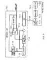
- FIG. 1is a block diagram of the broadcast system, according to the first example.
- 101denotes a data source
- 102denotes a power-line modulator
- 103denotes a power line
- 104 and 105denote outlets
- 106denotes an LED lighting element
- 107denotes a light reception terminal
- 111denotes an AC-DC converter
- 112denotes a band pass filter
- 113denotes a selector
- 114denotes a superimposing unit
- 115denotes an LED group.
- the data source 101may be constituted by apparatus, such as a TV, a CATV, a radio, and a tuner or a receiver for the CATV, as well as a computer, which are capable of outputting various data. Accordingly, what is broadcast may be various data, such as picture data, music data, sound data, image data, and character data. Moreover, what is broadcast may be a single piece of data or multiple pieces of data; it is assumed here that multiple pieces of data are output.
- the power-line modulator 102modulates and multiplexes multiple pieces of data output from the data source 101, superimposes the resulting data on an electric power waveform, and then transmits the resulting superimposed data waveform to the power line 103.
- ordinary power-line communication systemsoften include a demodulating means, which allows bi-directional communication; however, such a demodulating means is unnecessary for a broadcast system because the broadcast system allows only unidirectional communication.
- frequency divisionis carried out for multiplexing.
- the power line 103is an electric wire, which is provided indoors or outdoors.
- An existing electric wiremay be used as the power line 103.
- the outlets 104 and 105are fixed to a wall surface in order to receive power from the power line 103. Existing outlets may be used as the outlets 104 and 105.
- the power-line modulator 102is inserted into the outlet 104, and the LED lighting element 106 is inserted into the outlet 105.
- the power line 103 and the outlets 104 and 105may be newly provided. Note that with this exemplary structure, it is assumed that AC electric power used as general commercial electric power is supplied.
- the LED lighting element 106which is connected to the power line 103, illuminates in the vicinity thereof. In the case of indoors, for example, it is fixed to the ceiling. Other various lighting elements, such as a spotlight, are available for various applications.
- the LED lighting element 106includes the AC-DC converter 111, the band pass filter 112, the selector 113, the superimposing unit 114, and the LED group 115.
- the AC-DC converter 111converts AC electric power supplied from the power line 103 to DC electric power, which is supplied to the LED group 115 to emit light.
- a conventional AC-DC convertermay be used as the AC-DC converter 111.
- the AC-DC converter 111also makes an adjustment to the operating voltage for the LED group 115. Furthermore, it supplies electric power needed for operation of the band pass filter 112. Note that since a modulated data waveform is superimposed on the power line 103 as described above, it is desirable that a smoothing circuit, for example, should be used for preventing development of the data waveform on a DC waveform.
- the band pass filter 112is provided for extracting a data signal superimposed on the power line 103.
- the band pass filter 112which allows only a specific frequency to pass through, can selectively isolate single data from multiple pieces of data.
- multiple band pass filterseach allowing a different frequency to pass through, are arranged in parallel.
- a band pass filterwhich is capable of changing frequency bandwidths passed therethrough, may be arranged. Note that a separated data waveform may be biased, trimmed, or amplified.
- the selector 113selects one or more out of multiple filters in the band pass filter 112, thereby allowing selection of data to be optically distributed. This selection may be manually made; alternatively, it may be made using another method or by selectively demodulating a transmitted control signal of a specific frequency and then making a selection of a filter based on that control signal. Alternatively, a structure capable of changing frequencies that pass through the band pass filter 112 may be used, and the selector 113 may set a frequency corresponding to data to be distributed to the band pass filter 112. In FIG. 1 , the selector 113 is provided before the band pass filter 112; alternatively, it may be provided thereafter.
- the selector 113may set a frequency bandwidth for the band pass filter 112 in conformity with a control signal of a specific frequency. Furthermore, when the LED lighting element 106 broadcasts only data of a fixed frequency, the selector 113 is unnecessary, and only the band pass filter 112 that passes signals of a fixed frequency bandwidth should be provided.
- the superimposing unit 114superimposes a data signal extracted by the band pass filter 112 on a converted DC electric power waveform, which is provided by the AC-DC converter 111.
- Thisallows change in voltage applied to the LED group 115 in conformity with the resulting data signal, and control of light intensity or blinking of the LED group 115.
- a structuresuch that electric power from the AC-DC converter 111 is controlled to turn on and off in conformity with a signal from the band pass filter 112 is possible.
- the LED group 115is basically an LED light source for lighting, which may be constituted by a great number of white LEDs, for example. Needless to say, a structure with a set of red LEDs, a set of blue LEDs, and a set of green LEDs is possible. Electric power from the superimposing unit 114 is supplied to the LED group 115, which then emits light. Since LEDs have excellent response characteristics, they can output optical data through changing light intensity and/ or blinking in conformity with a data signal. In this case, since high-speed change in light intensity and/ or high-speed blinking is unperceivable to the human eye, LEDs may be used for lighting as they are.
- the light reception terminal 107has a light reception means, receives light illuminated from the LED lighting element 106, extracts a data signal therefrom and demodulates it into data.
- An arbitrary device including a light reception meansmay be used as the light reception terminal 107, and it may be a variety of apparatus, such as a personal computer, a portable terminal, a cellular phone, an audio device having a light reception means, or a display apparatus such as a television.
- Various contents to be broadcastedare prepared as the data source 101.
- various kinds of data from a TV, a CATV, and a radioare prepared for respective applications.
- the power-line modulator 102modulates and multiplexes multiple pieces of data output from the data source 101, superimposes the resulting data on an electric power waveform, and then transmits the resulting superimposed data waveform to the power line 103.
- FIG. 2is a graph describing an exemplary signal waveform of an electric wire.
- a commercial AC electric power supply50 Hz/ 60 Hz
- a data signal waveformis superimposed on an electric power waveform.
- a data signal waveformwhich is smaller than an electric power waveform, is superimposed so as to avoid adversely influencing other devices.
- a magnified view of FIG. 2(B)shows an instance of data modulated using a method such as binary phase shift keying (BPSK) and then superimposed on the electric power waveform.
- BPSKbinary phase shift keying
- an existing electric wiremay be used as the power line 103.
- receiving electric power from an outlet, separating and using dataallows provision of data as with the case of using conventional power-line communication.
- Electric power and dataare transmitted to the LED lighting element 106 from the outlet 105 via the power line 103.
- the LED lighting element 106receives from the outlet 105 electric power on which a signal waveform is superimposed.
- the AC-DC converter 111rectifies and supplies DC electric power, which is then used to drive the LED group 115, and transmits it to the superimposing unit 114.
- a filter in the band pass filter 112 selected by the selector 113passes and outputs only a predetermined frequency component. At this time, that component may be biased, trimmed, or amplified as necessary.
- the superimposing unit 114then combines DC electric power waveform, which is provided through conversion by the AC-DC converter 111, and a data signal extracted by the band pass filter 112, and then applies the resulting composite data signal waveform to the LED group 115.
- Voltage applied to the LED group 115varies depending on the composite data signal waveform. As a result, light intensity of the LED group 115 changes depending on the data signal waveform, which allows transmission of data.
- Light emitted from the LED group 115is received by a light reception device on the light reception terminal 107 side.
- the light reception terminal 107can receive data by detecting and demodulating changes in received light intensity. In this manner, of pieces of data provided from the data source 101, one selected by the LED lighting element 106 is transferred along with illuminative light; the light reception terminal 107 then receives that transferred data.
- the light reception unit in the light reception terminal 107may not exactly face the LED lighting element 106 (LED group 115); however, it is possible to capture a data signal as long as a certain degree of illuminative light can be received since communication quality is excellent. This is because the LED illuminative light is used for lighting and apparent transmitted electric power is extremely large.
- a signal with a similar signal intensityis transmitted using conventionally available infrared rays, influences on the human body (e.g., eyes) are unavoidable. In this regard, it is advantageous to optically transmit data.
- LED lighting element 106only a single LED lighting element 106 is shown in the drawing; however, if multiple LED lighting elements 106 are arranged at a short distance, this arrangement is resistant to shadowing and can accommodate movement as long as the same data is selected and broadcast. On the other hand, even if an LED lighting element 106 for selecting and broadcasting data exists at a short distance, since light from another LED lighting element attenuates as long as reception is made near an LED lighting element 106, its influence becomes weak. In addition, if a problem of interference with other LED lighting elements develops, data from the data source 101 should be modulated using an interference resistant modulation method, such as on-off keying, return-to-zero (OOK-RZ) or orthogonal frequency division multiplexing (OFDM).
- an interference resistant modulation methodsuch as on-off keying, return-to-zero (OOK-RZ) or orthogonal frequency division multiplexing (OFDM).
- the AC-DC converter 111 and the band pass filter 112are provided in the LED lighting element 106.
- this structureis not limited to this; alternatively, those circuits may be fixed in a light on/off wall switch, and DC electric power with a superimposed data waveform may be supplied between the switch and the LED lighting element 106.
- a switch to be used as the selector 113may be fixed to a wall along with a light on/off switch.
- arrangement of respective unitsis not limited to those proposals, and may arbitrarily be made.
- FIG. 3is a block diagram of a broadcast system, according to a second example.
- 116denotes a band pass filter
- 117denotes a determination unit
- 118denotes a selector.
- an identification code(such as IP, PN code) is assigned to each LED lighting element 106 or each piece of data, and only a specific piece of data is selected based on its own identification code and then broadcast.
- a power-line modulator 102divides multiple pieces of data from a data source 101 into packets, adds a header to the top of each packet, carries out time division multiplexing, and superimposes the resulting packets of data on the electric power waveform.
- the headerincludes an identification code.
- the LED lighting element 106includes the band pass filter 116, the determination unit 117, and the selector 118 as well as an LED group 115 and an AC-DC converter 111.
- the band pass filter 116removes AC components from electric power and separates data signal components. In this exemplary structure, all signals of multiple pieces of data pass through the band pass filter 116.
- the determination unit 117extracts a header from data signals separated by the band pass filter 116, compares it with a predetermined identification code, and determines whether or not the transmitted data should be optically transmitted. If YES, the selector 118 then selects a data signal and outputs it to a superimposing unit 114.
- the superimposing unit 114superimposes a signal passed through the selector 118 on a DC electric power waveform, which is provided through conversion by the AC-DC converter 111, and supplies the resulting superimposed signal to the LED group 115. Subsequently, as with the above-mentioned first example, light intensity or blinking of the LED group 115 is controlled based on a data signal, which allows optical data transmission. In addition, lighting comes from lights emitted by the LED group 115.
- each LED lighting element 106by assigning an identification code to, for example, each LED lighting element 106, data broadcast by each LED lighting element 106 can be controlled on a transmitter side from which data is transmitted to the power line 103. Moreover, a structure that allows assignment of separate identification codes allows selection of data to be broadcast from each LED lighting element 106. In this case, multiple identification codes may be assigned, and multiple pieces of data may be selected to be optically transmitted.
- the second examplemay be structured in different ways as with the above-mentioned first example.
- all data transmitted via the power line 103may be optically broadcast, and broadcast data may be received and selected on a terminal side.
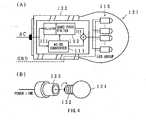
- FIG. 4is an explanatory diagram of an electric bulb applicable to the broadcast system, according to the first and second example.
- 121denotes an electric bulb
- 122denotes a base
- 123denotes a socket.
- the bulb shown in FIG. 4may be applied as a part of an LED lighting element 106 in the broadcast system, according to each example described above.
- a lighting element including an attachable incandescent bulbhas been available.
- the socket 123is arranged on the ceiling or the like, and electrical connection can be made by inserting the base 122 of the electric bulb 121 into the socket 123.
- the internal structure of the LED lighting element 106is accommodated in the electric bulb 121.
- that structuremay be accommodated in the base 122 of the electric bulb 121.
- a circuitcan be deployed therebehind.
- variously shaped conventional electric bulbsmay be used other than the shape as shown in FIG. 4 .
- the shape of the electric bulb 121is not limited to that in FIG. 4 , and it may be an arbitrary shape.
- the electric bulb 121may be structured with a form of linearly arranged LEDs such as a fluorescent lamp.
- FIG. 5is a diagram describing a first application, according to the first and second example.
- 131denotes LED lighting elements
- 132denotes artworks
- 133denotes a light reception terminal.
- FIG. 5shows a case of the broadcast system according to the first and second example for understanding the invention, which is used in an art gallery or a museum. In an art gallery or a museum, lighting such as spotlighting is used for each artwork or showpiece (hereafter, referred to as artworks 132) and description thereof.
- the LED lighting elements 131are used as lighting elements for illuminating the artworks 132.
- descriptive data for the artworks 132is superimposed on a power line 103 via which electric power is supplied to the LED lighting elements 131, and the resulting superimposed data is transmitted.
- descriptive data for a great number of artworks 132is superimposed on the power line 103.
- Each LED lighting element 131which is provided for each artwork 132, selectively extracts descriptive data for each artwork, and controls light intensity or blinking of illuminative light as described above, optically transmitting the descriptive data.
- an appreciatortakes out the light reception terminal 133 in front of an artwork 132
- lightis illuminated to the light reception terminal 133 and changes in the light intensity or blinking are captured and then demodulated, which allow the appreciator to read the descriptive data for the corresponding artwork 132.
- descriptive data for the next artworkis then transmitted via light for illuminating that artwork. As a result, the appreciator can read the descriptive data for that artwork displayed in the light reception terminal 133.
- each of the LED lighting elements 131 for illuminating respective artworksselects descriptive data for the corresponding artwork 132 and optically transmits the resulting selected data, which allows provision of lighting to each artwork 132 and also allows an appreciator to read descriptive data for each artwork 132.
- the LED lighting elements 131select multiple pieces of descriptive data for artworks 132 to be illuminated, and optically transmit the selected data.
- the light reception terminal 133then separates and demodulates optically transmitted, multiple pieces of descriptive data, selects descriptive data in a language of choice specified by the appreciator, and presents it to the appreciator.
- a structuresuch that the same LED lighting element 131 optically transmits multiple pieces of descriptive data for a single artwork 132, such as descriptive data for adults and that for children, is possible.
- descriptive datais not limited to text data, and may be sound data, image data, or animation data. Alternatively, a combination thereof is also possible.
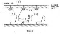
- FIG. 6is a diagram describing a second application, according to the first and second example.
- 141denotes LED lighting elements
- 142 and 143denote seats
- 144denotes light reception terminals.
- the second applicationshows a case of the broadcast system, according to the first and second example, used in an airplane, a train, or a bus.
- the LED lighting elements 141are provided to the respective seats, illuminating them.
- the LED lighting elements 141also optically transmit data, which is transmitted via the power line 103.
- the light reception terminal 144is provided in the backside of the front seat 142 so that a passenger seated in the seat 143 can see the screen of the light reception terminal 144.
- the light reception terminal 144receives light illuminated from an LED lighting element 141, and captures data from the light. A passenger may select and view desired data through manipulation of the light reception terminal 144.
- wireless data distributionmay be carried out as shown in FIG. 6 .
- datamay be selected by the light reception terminal 144 in addition to the LED lighting element 141.
- the AC-DC converter 111 in FIGS. 1 and 3is unnecessary.
- the band pass filter 112 and the superimposing unit 114are unnecessary.
- Datamay be optically transmitted by driving the LED group with data waveform superimposed electric power, which is supplied from the power line 103.
- the present inventionis not limited to those applications, and can be applied to various applications for optically distributing data.
- itcan be used as a distribution system, which distributes to a personal computer on a desk in an ordinary office, and may be used for transmitting data to each process in a factory.
- broadcasting a television program or a radio program in a homeis also possible, and that program can be viewed in any room using a portable display.
- a selector or a tunermay be provided in the LED lighting element, and a broadcasting station may be selected by controlling the selector using a television controller.
- information of sports or events or information of other hallsis superimposed on illuminative light and broadcast, and a portable terminal owned by a spectator receives it and provides that information for the spectator.
- a great number of pieces of datamay be optically distributed using lighting elements as they are.
- a broadcast systemcan be constructed at low cost.
- the present inventionis an application to emergency lights.
- emergency lightssemi-permanently continue to illuminate and are hardly ever switched off once they are switched on.
- many emergency lightsare deployed in plain view, such as in a building, a theater, a film theater, a hospital, an airport, and a station.
- the majority of present emergency lightsuses a fluorescent lamp as a light source. Since it is expected that external electric power may be turned off when a disaster occurs, an internal battery is used to supply electric power to emergency lights to illuminate while in an emergency. Fluorescent lamps having better electric power efficiency than incandescent bulbs are used for effective utilization of limited electric power. Meanwhile, reduction in maintenance cost using a light source having further excellent electric power efficiency and a long-lived light source has been required.
- LEDshave excellent electric power efficiency and a long operating life, but they have not been considered to be used as emergency lights.
- LEDshave never been used as a main light source for emergency lights.
- ordinary emergency lights deployed in placemerely provide visual information of where emergency exits and emergency staircases are located.
- Japanese Patent Application Laid-Open No. Hei 8-299475in which a voice guiding mechanism is provided
- Japanese Patent Application Laid-Open No. Hei 8-67203in which radio broadcasting is used.
- large electric poweris needed for voice output. Therefore, a large-capacity battery must be embedded for visual indication of the emergency exits, which is the first principle for the emergency lights, and for voice output, thereby developing problems of increase in cost and system size.
- LEDshave a high-speed response characteristic and can be modulated at a high speed
- use of LEDs for optical data communicationhas been studied.
- the idea of using these features and carrying out illumination and communication at the same timehas been well-known.
- ordinary lighting elementsare switched off when power supply stops due to a disaster. Therefore, those devices cannot be used while in an emergency, and there has been no communication system established assuming an emergency.
- the present inventionshows an application of light emitted from emergency lights for communication.
- FIG. 55is a block diagram of an emergency light and a wireless emergency light data communication system, according to an embodiment of the present invention.
- FIG. 56is a diagram describing an exemplary LED array used as a light source.
- 701denotes an emergency light
- 702denotes a portable terminal
- 711denotes a battery
- 712denotes a switch
- 713denotes an LED array
- 714denotes a modulator/ demodulator
- 715denotes data memory
- 716denotes an optical modulator
- 721denotes a light receiving unit
- 722denotes a demodulator
- 723denotes a display unit
- 731denotes a cover.
- the emergency light 701has the battery 711 as a power source in addition to an external power source, as with typical conventional emergency lights, and the switch 712 to switch a power supply source from the external power source to the battery 711 when power supply from the external power source stops.
- the LED array 713instead of a conventional fluorescent light, is used as the illuminative light source.
- FIG. 56shows an exemplary shape of the LED array 713.
- the LED array 713is provided in the cover 731 on which a pictorial mark is displayed.
- the rod-shaped LED array 713 similar to a fluorescent lampis used, as shown in FIG. 56(B).
- LED devicesshould be arranged in one or more rows.
- such LED array 713may be used as a substitute for a DC lighting fluorescent lamp.
- the emergency lightmay be structured only by replacing a fluorescent light in the conventionally available emergency light with the LED array 713 as shown in FIG. 56(B).
- the emergency lightwhen AC electric power is supplied from a power line, the emergency light should be driven by DC electric power, which is provided through conversion by an AC-DC converter.
- a DC-AC convertershould be embedded in the LED array 713 and used while being driven by the battery 711. Note that use of this such-shaped LED array 713, which can be substituted for a fluorescent lamp, allows provision of the emergency light with the same shape as that of the conventional emergency light in appearance.
- the LED array 713may directly display a pictorial mark, which has been put on the cover 731, as shown in FIG. 56(C).
- a pictorial markindicating emergency exits
- the pictorial marksince the pictorial mark is typically designed in white and green, it can be displayed by arranging white and green LEDs in place.
- a pictorial markmay be displayed by arranging LEDs in the same manner as a color display apparatus. Note that in such cases, a transparent material should be used as the cover 731.
- an LED arrayas a light source for the emergency light 701 in this manner and an advantage of LEDs having low power consumption allows provision of the same lighting time with a small-capacity battery as that by prior art, reduction in size of the battery 711, reduction in size and weight of the emergency light 701, and reduction in cost.
- the emergency lightmay be on over a long period of time, allowing an escape guiding display to be displayed for a long time when a disaster occurs.
- a feature of long-lived LEDsallows extension of maintenance intervals, such as replacement of a light source, and decrease in man-hour for maintenance work, resulting in reduction in maintenance cost.
- the emergency light 701 according to the present invention shown in FIG. 55further includes the modulator/ demodulator 714, the data memory 715, and the optical modulator 716.
- a communication method using a power line for supplying electric power from the external power sourceis used for transmitting data to the emergency light 701.
- the modulator/ demodulator 714separates and demodulates modulated data which is superimposed on a voltage from the external power source, and then stores the resulting demodulated data in the data memory 715.
- data to be transmitted from the emergency light 701 while in an emergencycan be transmitted from a computer via a power line. Accordingly, data may be distributed to the emergency light 701 via an external power source while not in an emergency, which allows easy storage of data in the data memory 715.
- various pieces of datasuch as data stored in the data memory 715 or the status of the emergency light 701, may be modulated and then transmitted via the power line. This allows remote confirmation of rewritten data and remote determination of the operation of the emergency light 701.
- the modulator/ demodulator 714may be structured to function as a mere demodulator. In the case of data to be transmitted while in an emergency being pre-stored in the data memory 715, the modulator/ demodulator 714 is unnecessary.
- Data to be transmitted while in an emergencymay be stored in the data memory 715. It is desirable that the power consumption of the data memory 715 is minimal. In addition, it is necessary to prevent stored data from being accidentally erased while changing over the power source. For example, rewritable ROM or nonvolatile RAM should be used.
- the optical modulator 716Upon detection of an emergency, such as an event of the switch 712 having changed over from the external power source to the battery 711, the optical modulator 716 reads out data to be transmitted while in an emergency from the data memory 715, modulates it, and then superimposes the resulting modulated data on an electric power waveform that is supplied to the LED array 713. This allows control of blinking or light intensity of light emitted from the LED array 713 in accordance with data modulated by the optical modulator 716. This allows optical data communication. Needless to say, even while not in an emergency, data communication is possible by modulating data stored in the data memory 715 and providing the resulting modulated data to the LED array 713. In this case, data may differ from that to be transmitted while in an emergency.
- the portable terminal 702which includes the light receiving unit 721, the demodulator 722, and the display unit 723, may be, for example, a PDA with a camera or a cellular phone with a camera.
- the demodulator 722extracts a modulated data signal from an electric signal transmitted from the light receiving unit 721, demodulates it, and then captures data.
- the captured datais available for various applications.
- the captured datais displayed on the display unit 723.
- data optically transmitted from the emergency light 701 while in an emergencyis displayed on the display unit 723.
- Text and picture datasuch as a map regarding emergency exits or escape routes for evacuees on a floor, may be displayed on the display unit 723.
- voice datamay be transmitted, and if a speaker is embedded like a cellular phone, voice data can be easily captured.
- Data to be transmitted to the data memory 715 while in an emergencyshould be pre-stored in the emergency light 701.
- power line communicationis used for transmitting modulated data, as described above, which is superimposed on an external power source waveform, to the emergency light 701, which then receives and demodulates modulated data transmitted from the external power source, thereby capturing data.
- datais pre-stored in external ROM, and the external ROM may be fixed, as the data memory 715, to the emergency light 701.
- a memory cardmay be fixed thereto.
- the optical modulator 716reads out data from the data memory 715, modulates it, and then superimposes the resulting modulated data on an electric power source waveform to be supplied to the LED array 713.
- the LED array 713When the electric power on which modulated data is superimposed is supplied to the LED array 713, the LED array 713 then emits light, and light intensity or blinking is controlled allowing optical data transmission.
- a possessor of the portable terminal 702can receive data optically transmitted from the emergency light 701 by facing the possessed portable terminal 702 to the emergency light 701 while in an emergency. While in an emergency, people often get lost, and even while evacuating according to emergency lights, they may feel anxious about no information as to how long it takes to evacuate.
- various pieces of visual datasuch as building names, a map of staircases and floors, escape routes for evacuees, and a remaining distance in meters from emergency exits, which the conventional emergency light cannot provide, can be obtained from the emergency light 701. This eases anxiety to a certain extent, allowing more rapid evacuation.
- the portable terminal 702may often be driven by a battery, it may be effectively used while in an emergency. Accordingly, use of the emergency light, which emits light without an external power source while in an emergency, and the portable terminal 702, which does not need the external power source, together allows smooth escape guidance while in an emergency, in particular, even when the external power source is cut off.
- the emergency light 701needs electric power to be supplied to the optical modulator 716 or related units.
- necessary electric power for such electronic circuits to operateis much less than electric power for emitting light. Therefore, even when including such optical data communication capability, reinforcement of the battery 711 for the emergency light 701 is almost unnecessary.
- optical data communication using an LED light sourceis advantageous.
- the LED array 713 in the emergency light 701emits light to display guidance to emergency exits and escape routes for evacuees as with the typical emergency light, and is effective for people who do not have the portable terminal 702 while in an emergency. Even when light intensity and/ or blinking is controlled for data communication, such change in light intensity is unperceivable to the human eye. Therefore, the functionality as the emergency light will not be lost. In addition to this, utilization of the features of LEDs provides further enhanced functionality as an emergency light than that of the conventional emergency light.
- data communication by the emergency light 701is not limited to an emergency.
- data stored in the data memory 715may always be optically transmitted.
- the emergency light 701is switched on, it is never switched off and is always on day and night. Therefore, a user of the portable terminal 702 can always capture data from the emergency light 701.
- the content of the data memorycan be updated as needed through power line communication as described above, real time distribution of data to the portable terminal 702 while not in an emergency is possible.
- FIG. 57is a block diagram of an emergency light and a wireless emergency light data communication system, according to another embodiment of the seventh aspect of the present invention.
- 741denotes an antenna
- 742denotes a modulator/ demodulator.
- the emergency light 701receives data transmitted from the outside via radio wave and then stores it in the data memory 715.
- Data received by the antenna 741is demodulated by the modulator/ demodulator 742, and the resulting demodulated data is then stored in the data memory 715.
- Such data receptionshould be carried out while not in an emergency. Since electric power can be supplied from the external power source while in an emergency, such radio wave data reception is possible. Needless to say, in the case of broadcasting data, mere demodulating capability is required to the modulator/ demodulator 742.
- a communication linesuch as an optical cable or a communication cable, except for a power line may be utilized to receive data in advance.
- a communication linesuch as an optical cable or a communication cable, except for a power line may be utilized to receive data in advance.
- use of power line communication shown in FIG. 55develops an advantage that data reception is possible without deploying an antenna or an additional cable.
- LEDsas a light source allows suppression of battery consumption due to high electric power efficiency of LEDs, reduction in device size due to a reduced battery size, and an extended light emitting time. Moreover, since LEDs have a long operating life, maintenance intervals such as light source replacement intervals can be longer, allowing reduction in maintenance cost. Furthermore, since LEDs are highly crashproof, provision of an emergency light that will not be damaged and be available even when a devastating disaster occurs is possible.
- LEDssince LEDs have excellent response characteristics, they may be used as an optical data transmission source by controlling blinking or light intensity thereof.
- the emergency lightincludes a battery, allowing continuous light emission even when the electric power supply is cut off due to a disaster.
- Various pieces of emergency datasuch as positional data for emergency exits and emergency staircases, and data for escape routes for evacuees to the emergency exits, which have been pre-stored, can be transmitted using this emitted light. Since provision of such data transmission capability is not costly and does not consume much electric power as compared to the case of providing an additional radio wave or an additional infrared ray transmission system, the capability of emitting light as an emergency light while in an emergency is not lost.
- the emergency lightis switched on, it is not switched off semi-permanently and is not influenced by weather and seasons. Therefore, it is generally provided in plain view. Moreover, transmission of not only emergency data, but also general data, such as surrounding advertisements or guidance, is possible. Accordingly, it is expected that the emergency light will be frequently used even while not in an emergency, allowing increase in added value of the emergency light.
Landscapes
- Engineering & Computer Science (AREA)
- Computer Networks & Wireless Communication (AREA)
- Signal Processing (AREA)
- Physics & Mathematics (AREA)
- Electromagnetism (AREA)
- General Physics & Mathematics (AREA)
- Power Engineering (AREA)
- Computing Systems (AREA)
- Theoretical Computer Science (AREA)
- Business, Economics & Management (AREA)
- Emergency Management (AREA)
- General Engineering & Computer Science (AREA)
- Optical Communication System (AREA)
- Circuit Arrangement For Electric Light Sources In General (AREA)
- Selective Calling Equipment (AREA)
Abstract
Description
- The present invention relates to a technology that contributes to illuminative light communication.
WO 02/25842 A2 - An article byKomine and Nakagawa, which was a contribution to the 13th IEEE international symposium on personal, indoor and mobile radio communications in September 2002 in PISCATA-WAY, NJ, USA (IEEE, vol. 4, 15 September 2002, p. 1762 - 1766) describes an integrated system of white LED visible-light communication and power-line communication. The paper proposes an easy wiring system for optical communication using existing power-line.
DE 41 37 032 A1 relates to a device for an optical data communication using a light source emitting light that hits on the transmitting side a retro reflector. An optical modulator is arranged in front of the retro reflector and modulates the reflected light in accordance with data to be transmitted.JP 2001-176678 - In recent years, a radio wave communication system has become available along with portable terminals. Recently, shorter wavelength infrared rays have been widely used due to available frequency depletion. Other than available frequency depletion, radio waves may influence medical devices or various precision equipment. Moreover, there is fear that infrared rays may adversely influence the human body (e.g., eyes). As a result, optical communication is in the spotlight as a safe communication method.
- Meanwhile, white LEDs are developed owing to the success of development of blue LEDs. The features of white LEDs are: extremely lower power consumption than that of conventional incandescent lamps or fluorescent lamps, small size, and long life. Accordingly, use of white LEDs as a illuminative light source is considered. Another feature of white LEDs is a fast response speed relative to supplied power. Paying attention to these features, a study of electrically controlling blinking or light intensity and thereby transferring a signal has been conducted.
- A study of integration of such signal transfer using white LED lights with the aforementioned power-line communication system has been conducted. For example, a proposal regarding that study has been disclosed in'INTEGRATED SYSTEM OF WHITE LED VISIBLE-LIGHT COMMUNICATION AND POWER-LINE COMMUNICATION written by inventors: T. Komine, Y. Tanaka, and M. Nakagawa, Institute of Electronics, Information, and Communication Engineers Technical Research Report, The Institute of Electronics, Information, and Communication Engineers, March 12, 2002, Vol. 101, No. 726, pp. 99 - 104. Since such system utilizes lights, there are no effects on the human body, allowing safe communication. In addition, other applications are expected.
- The present invention, aims to provide an emergency light including a light source having excellent electric power efficiency and long operating life, a wireless emergency light data transmission system that uses the emergency light as a data transmission source while in an emergency, and an emergency light that is used in the system. Such an object is achieved by an emergency lamp according to
claim 1 and wireless emergency lamp data transmission system according to claim 3. Further developments are described in the dependent claims. - An emergency light, which is embedded with a battery and turns a light source on while in an emergency without electric power supplied from an external power source, is characterized by the light source made up of LEDs. The feature of LEDs or high electric power efficiency allows suppression of battery consumption. Reduced battery size allows reduction in device size. Moreover, extended operating life as to light emitting time is provided. Moreover, since LEDs have a long operating life, intervals between maintenance such as light source replacement intervals can be extended, which allows reduction in maintenance cost. Furthermore, since LEDs are highly crashproof, an available emergency light that will not be damaged due to a devastating disaster can be provided.
- The emergency light further includes a storage unit that is stored with data to be transmitted while in an emergency and an optical modulator that controls electric power supplied to the LEDs in accordance with data stored in the storage unit, so as for the LEDs to change light intensity or blink. As described above, since LEDs have an excellent response speed characteristic, modulation based on such data is possible, and light for displaying can be used for data transmission as is. With such structure, the emergency light, which is conventionally used merely for indicating an emergency exit and an emergency staircase, can be used as a data source while in an emergency. At this time, since the light source, which functions as an emergency light, is used as is, it never consumes large electric power as opposed to the case of voice output. As a result, most of electric power consumption is expected to be an amount for only the light source. As a result, there is no need to provide an additional large-capacity battery for transmitting data, thereby allowing the light source to operate as a data source with a battery provided for display.
- Alternatively, a demodulator may be provided, so as to separate data, which is superimposed on a voltage of an external power source and then transmitted, while being driven by an external power source while not at a time other than in an emergency. Data provided from the modulator is then stored in a storage unit. Such a structure allows distribution of data, which is to be transmitted while in an emergency, to respective emergency lights via the power line while not in an emergency. As a result, data to be transmitted while in an emergency can be easily set and updated.
- Further, a wireless emergency light data transmission system for transmitting data to a terminal using an emergency light, which has a light source turned on while in an emergency without electric power supplied from an external power source, is provided. In the wireless emergency light data transmission system, the emergency light includes a battery, an LED that is used as a light source, a storage unit that is stored with data to be transmitted while in an emergency, and an optical modulator that controls electric power supplied to the LED in accordance with data stored in the storage unit, thereby controlling light intensity or blinking of the LED. The terminal includes a light receiving unit that receives light emitted from the LED in the emergency light and converts it to an electric signal, and a demodulator that demodulates the electric signal output from the light receiving unit, thereby capturing the data. This structure allows optical data transmission from an emergency light to a terminal while in an emergency. Various pieces of data such as escape routes for evacuees, informing destination, or a map and descriptive text data for floors can be displayed on the terminal, which allows smoothly guiding users to evacuate while in an emergency.
FIG. 1 is a block diagram of a broadcast system, according to a first example for understanding the present invention;FIG. 2(A) is a diagram describing an exemplary signal waveform of an electric wire;FIG. 2(B) is a partially magnified diagram thereof,FIG. 3 is a block diagram of a broadcast system, according to a second example for understanding the present invention;FIG. 4(A) is an explanatory diagram of an electric bulb applicable to the broadcast system, according to the first and second example for understanding the present invention;FIG. 4(B) is a diagram describing how to detach the electric bulb;FIG. 5 is a diagram describing a first application of the first and second example ;FIG. 6 is a diagram describing a second application of the first and second example ;FIG. 7 . is a block diagram of an emergency light and a wireless emergency light data communication system, according to an embodiment of the present invention;FIG. 8 shows an exemplary LED array used as a light source; FIG. 56(A) shows an appearance of an emergency light when a cover is removed; FIG. 56(B) shows an exemplary LED array to be used; and FIG. 56(C) shows an another example of a pictorial mark formed on the cover;FIG. 9 is a block diagram of an emergency light and a wireless emergency light data communication system, according to an embodiment of the present invention;- Useful Examples for Understanding the invention
- Useful examples for understanding the present invention are described forthwith. These examples relate to a broadcast system that optically broadcasts data, and an electric bulb preferable for the same.
- A power-line communication system has been studied as one of communication systems. The power-line communication system transmits data using a power line, which is provided in a house or a building as a signal transmission medium. The power line is a very popular infrastructure, which basically allows communication among devices connected via the power line. Meanwhile, communication among devices, such as portable terminals, not connected via the power line is impossible. The examples provide a broadcast system, which broadcasts data to many devices not connected via the power line.
FIG. 1 is a block diagram of the broadcast system, according to the first example. In the drawing, 101 denotes a data source, 102 denotes a power-line modulator, 103 denotes a power line, 104 and 105 denote outlets, 106 denotes an LED lighting element, 107 denotes a light reception terminal, 111 denotes an AC-DC converter, 112 denotes a band pass filter, 113 denotes a selector, 114 denotes a superimposing unit, and 115 denotes an LED group. Thedata source 101 may be constituted by apparatus, such as a TV, a CATV, a radio, and a tuner or a receiver for the CATV, as well as a computer, which are capable of outputting various data. Accordingly, what is broadcast may be various data, such as picture data, music data, sound data, image data, and character data. Moreover, what is broadcast may be a single piece of data or multiple pieces of data; it is assumed here that multiple pieces of data are output.- The power-
line modulator 102 modulates and multiplexes multiple pieces of data output from thedata source 101, superimposes the resulting data on an electric power waveform, and then transmits the resulting superimposed data waveform to thepower line 103. Note that ordinary power-line communication systems often include a demodulating means, which allows bi-directional communication; however, such a demodulating means is unnecessary for a broadcast system because the broadcast system allows only unidirectional communication. In addition, according to an exemplary data multiplexing method, frequency division is carried out for multiplexing. - Typically, the
power line 103 is an electric wire, which is provided indoors or outdoors. An existing electric wire may be used as thepower line 103. In addition, the outlets 104 and 105 are fixed to a wall surface in order to receive power from thepower line 103. Existing outlets may be used as the outlets 104 and 105. In the exemplary structure shown inFIG. 1 , the power-line modulator 102 is inserted into the outlet 104, and theLED lighting element 106 is inserted into the outlet 105. Needless to say, thepower line 103 and the outlets 104 and 105 may be newly provided. Note that with this exemplary structure, it is assumed that AC electric power used as general commercial electric power is supplied. - The
LED lighting element 106, which is connected to thepower line 103, illuminates in the vicinity thereof. In the case of indoors, for example, it is fixed to the ceiling. Other various lighting elements, such as a spotlight, are available for various applications. In this exemplary structure, theLED lighting element 106 includes the AC-DC converter 111, theband pass filter 112, theselector 113, the superimposingunit 114, and theLED group 115. - The AC-
DC converter 111 converts AC electric power supplied from thepower line 103 to DC electric power, which is supplied to theLED group 115 to emit light. A conventional AC-DC converter may be used as the AC-DC converter 111. In addition, the AC-DC converter 111 also makes an adjustment to the operating voltage for theLED group 115. Furthermore, it supplies electric power needed for operation of theband pass filter 112. Note that since a modulated data waveform is superimposed on thepower line 103 as described above, it is desirable that a smoothing circuit, for example, should be used for preventing development of the data waveform on a DC waveform. - The
band pass filter 112 is provided for extracting a data signal superimposed on thepower line 103. As described above, with this exemplary structure, since individual pieces of data are multiplexed through frequency division, theband pass filter 112, which allows only a specific frequency to pass through, can selectively isolate single data from multiple pieces of data. In the example shown inFIG. 1 , multiple band pass filters, each allowing a different frequency to pass through, are arranged in parallel. Alternatively, a band pass filter, which is capable of changing frequency bandwidths passed therethrough, may be arranged. Note that a separated data waveform may be biased, trimmed, or amplified. - The
selector 113 selects one or more out of multiple filters in theband pass filter 112, thereby allowing selection of data to be optically distributed. This selection may be manually made; alternatively, it may be made using another method or by selectively demodulating a transmitted control signal of a specific frequency and then making a selection of a filter based on that control signal. Alternatively, a structure capable of changing frequencies that pass through theband pass filter 112 may be used, and theselector 113 may set a frequency corresponding to data to be distributed to theband pass filter 112. InFIG. 1 , theselector 113 is provided before theband pass filter 112; alternatively, it may be provided thereafter. In addition, in the case of that structure capable of changing a frequency band that theband pass filter 112 passes, theselector 113 may set a frequency bandwidth for theband pass filter 112 in conformity with a control signal of a specific frequency. Furthermore, when theLED lighting element 106 broadcasts only data of a fixed frequency, theselector 113 is unnecessary, and only theband pass filter 112 that passes signals of a fixed frequency bandwidth should be provided. - The superimposing
unit 114 superimposes a data signal extracted by theband pass filter 112 on a converted DC electric power waveform, which is provided by the AC-DC converter 111. This allows change in voltage applied to theLED group 115 in conformity with the resulting data signal, and control of light intensity or blinking of theLED group 115. For example, in the case of making theLED group 115 blink, a structure such that electric power from the AC-DC converter 111 is controlled to turn on and off in conformity with a signal from theband pass filter 112 is possible. - The
LED group 115 is basically an LED light source for lighting, which may be constituted by a great number of white LEDs, for example. Needless to say, a structure with a set of red LEDs, a set of blue LEDs, and a set of green LEDs is possible. Electric power from the superimposingunit 114 is supplied to theLED group 115, which then emits light. Since LEDs have excellent response characteristics, they can output optical data through changing light intensity and/ or blinking in conformity with a data signal. In this case, since high-speed change in light intensity and/ or high-speed blinking is unperceivable to the human eye, LEDs may be used for lighting as they are. - The
light reception terminal 107 has a light reception means, receives light illuminated from theLED lighting element 106, extracts a data signal therefrom and demodulates it into data. An arbitrary device including a light reception means may be used as thelight reception terminal 107, and it may be a variety of apparatus, such as a personal computer, a portable terminal, a cellular phone, an audio device having a light reception means, or a display apparatus such as a television. - An exemplary operation of the broadcast system, according to the first example is briefly described forthwith. Various contents to be broadcasted are prepared as the
data source 101. For example, in addition to data from a computer, various kinds of data from a TV, a CATV, and a radio are prepared for respective applications. - The power-
line modulator 102 modulates and multiplexes multiple pieces of data output from thedata source 101, superimposes the resulting data on an electric power waveform, and then transmits the resulting superimposed data waveform to thepower line 103.FIG. 2 is a graph describing an exemplary signal waveform of an electric wire. Here, a commercial AC electric power supply (50 Hz/ 60 Hz) is used, and a data signal waveform is superimposed on an electric power waveform. A data signal waveform, which is smaller than an electric power waveform, is superimposed so as to avoid adversely influencing other devices. A magnified view ofFIG. 2(B) shows an instance of data modulated using a method such as binary phase shift keying (BPSK) and then superimposed on the electric power waveform. Note that an existing electric wire may be used as thepower line 103. In addition, receiving electric power from an outlet, separating and using data allows provision of data as with the case of using conventional power-line communication. - Electric power and data are transmitted to the
LED lighting element 106 from the outlet 105 via thepower line 103. TheLED lighting element 106 receives from the outlet 105 electric power on which a signal waveform is superimposed. The AC-DC converter 111 rectifies and supplies DC electric power, which is then used to drive theLED group 115, and transmits it to thesuperimposing unit 114. On the other hand, a filter in theband pass filter 112 selected by theselector 113 passes and outputs only a predetermined frequency component. At this time, that component may be biased, trimmed, or amplified as necessary. - The superimposing
unit 114 then combines DC electric power waveform, which is provided through conversion by the AC-DC converter 111, and a data signal extracted by theband pass filter 112, and then applies the resulting composite data signal waveform to theLED group 115. Voltage applied to theLED group 115 varies depending on the composite data signal waveform. As a result, light intensity of theLED group 115 changes depending on the data signal waveform, which allows transmission of data. - Light emitted from the
LED group 115 is received by a light reception device on thelight reception terminal 107 side. Thelight reception terminal 107 can receive data by detecting and demodulating changes in received light intensity. In this manner, of pieces of data provided from thedata source 101, one selected by theLED lighting element 106 is transferred along with illuminative light; thelight reception terminal 107 then receives that transferred data. In this case, the light reception unit in thelight reception terminal 107 may not exactly face the LED lighting element 106 (LED group 115); however, it is possible to capture a data signal as long as a certain degree of illuminative light can be received since communication quality is excellent. This is because the LED illuminative light is used for lighting and apparent transmitted electric power is extremely large. When a signal with a similar signal intensity is transmitted using conventionally available infrared rays, influences on the human body (e.g., eyes) are unavoidable. In this regard, it is advantageous to optically transmit data. - Note that: only a single
LED lighting element 106 is shown in the drawing; however, if multipleLED lighting elements 106 are arranged at a short distance, this arrangement is resistant to shadowing and can accommodate movement as long as the same data is selected and broadcast. On the other hand, even if anLED lighting element 106 for selecting and broadcasting data exists at a short distance, since light from another LED lighting element attenuates as long as reception is made near anLED lighting element 106, its influence becomes weak. In addition, if a problem of interference with other LED lighting elements develops, data from thedata source 101 should be modulated using an interference resistant modulation method, such as on-off keying, return-to-zero (OOK-RZ) or orthogonal frequency division multiplexing (OFDM). - In addition, in the exemplary structure shown in
FIG. 1 , the AC-DC converter 111 and theband pass filter 112 are provided in theLED lighting element 106. However, this structure is not limited to this; alternatively, those circuits may be fixed in a light on/off wall switch, and DC electric power with a superimposed data waveform may be supplied between the switch and theLED lighting element 106. In this case, a switch to be used as theselector 113 may be fixed to a wall along with a light on/off switch. Needless to say, arrangement of respective units is not limited to those proposals, and may arbitrarily be made. FIG. 3 is a block diagram of a broadcast system, according to a second example. In the drawing, the same reference numerals are given to the same parts as those inFIG. 1 , and repetitive descriptions thereof are thus omitted. 116 denotes a band pass filter, 117 denotes a determination unit, and 118 denotes a selector. In this exemplary structure, an identification code (such as IP, PN code) is assigned to eachLED lighting element 106 or each piece of data, and only a specific piece of data is selected based on its own identification code and then broadcast.- A power-
line modulator 102 divides multiple pieces of data from adata source 101 into packets, adds a header to the top of each packet, carries out time division multiplexing, and superimposes the resulting packets of data on the electric power waveform. The header includes an identification code. - The
LED lighting element 106 includes theband pass filter 116, the determination unit 117, and theselector 118 as well as anLED group 115 and an AC-DC converter 111. Theband pass filter 116 removes AC components from electric power and separates data signal components. In this exemplary structure, all signals of multiple pieces of data pass through theband pass filter 116. - The determination unit 117 extracts a header from data signals separated by the
band pass filter 116, compares it with a predetermined identification code, and determines whether or not the transmitted data should be optically transmitted. If YES, theselector 118 then selects a data signal and outputs it to asuperimposing unit 114. The superimposingunit 114 superimposes a signal passed through theselector 118 on a DC electric power waveform, which is provided through conversion by the AC-DC converter 111, and supplies the resulting superimposed signal to theLED group 115. Subsequently, as with the above-mentioned first example, light intensity or blinking of theLED group 115 is controlled based on a data signal, which allows optical data transmission. In addition, lighting comes from lights emitted by theLED group 115. - According to the second example, by assigning an identification code to, for example, each
LED lighting element 106, data broadcast by eachLED lighting element 106 can be controlled on a transmitter side from which data is transmitted to thepower line 103. Moreover, a structure that allows assignment of separate identification codes allows selection of data to be broadcast from eachLED lighting element 106. In this case, multiple identification codes may be assigned, and multiple pieces of data may be selected to be optically transmitted. - The second example may be structured in different ways as with the above-mentioned first example. In addition, there are the same advantages as those of the above-mentioned first example.
- In addition to those examples, without selecting data to be broadcast using illuminative light, all data transmitted via the
power line 103 may be optically broadcast, and broadcast data may be received and selected on a terminal side. FIG. 4 is an explanatory diagram of an electric bulb applicable to the broadcast system, according to the first and second example. In the drawing, 121 denotes an electric bulb, 122 denotes a base, and 123 denotes a socket. The bulb shown inFIG. 4 may be applied as a part of anLED lighting element 106 in the broadcast system, according to each example described above. Typically, a lighting element including an attachable incandescent bulb has been available. As shown inFIG. 4(B) , thesocket 123 is arranged on the ceiling or the like, and electrical connection can be made by inserting thebase 122 of theelectric bulb 121 into thesocket 123. Here, existing facility in the interconnect portion extending until thepower line 103 or thesocket 123 is used as is, and as shown inFIG. 4(A) , the internal structure of theLED lighting element 106, according to the first or the second example described above, is accommodated in theelectric bulb 121. For example, that structure may be accommodated in thebase 122 of theelectric bulb 121. In addition, differing from conventional point light sources with a filament such as an incandescent bulb, since a great number of LEDs are deployed in the same plane, a circuit can be deployed therebehind.- Use of such
electric bulb 121 and only replacement of a typical incandescent bulb with theelectric bulb 121, according to the first and second example allows use of theelectric bulb 121 as an optical data transmission source. - Needless to say, variously shaped conventional electric bulbs may be used other than the shape as shown in
FIG. 4 . The shape of theelectric bulb 121, according to the first and second example, is not limited to that inFIG. 4 , and it may be an arbitrary shape. For example, theelectric bulb 121 may be structured with a form of linearly arranged LEDs such as a fluorescent lamp. - Next, several applications of the broadcast system, according to the first and second example, are described forthwith.
FIG. 5 is a diagram describing a first application, according to the first and second example. In the drawing, 131 denotes LED lighting elements, 132 denotes artworks, and 133 denotes a light reception terminal.FIG. 5 shows a case of the broadcast system according to the first and second example for understanding the invention, which is used in an art gallery or a museum. In an art gallery or a museum, lighting such as spotlighting is used for each artwork or showpiece (hereafter, referred to as artworks 132) and description thereof. The LED lighting elements 131, according to the first and second example, are used as lighting elements for illuminating theartworks 132. On the other hand, descriptive data for theartworks 132 is superimposed on apower line 103 via which electric power is supplied to the LED lighting elements 131, and the resulting superimposed data is transmitted. In this case, descriptive data for a great number ofartworks 132 is superimposed on thepower line 103. Each LED lighting element 131, which is provided for eachartwork 132, selectively extracts descriptive data for each artwork, and controls light intensity or blinking of illuminative light as described above, optically transmitting the descriptive data. - When an appreciator takes out the
light reception terminal 133 in front of anartwork 132, light is illuminated to thelight reception terminal 133 and changes in the light intensity or blinking are captured and then demodulated, which allow the appreciator to read the descriptive data for thecorresponding artwork 132. In addition, when the appreciator moves in front of the next artwork, descriptive data for the next artwork is then transmitted via light for illuminating that artwork. As a result, the appreciator can read the descriptive data for that artwork displayed in thelight reception terminal 133. - In this manner, descriptive data for each
artwork 132 is superimposed on an electric power waveform and then transmitted to thepower line 103, and on the other hand, each of the LED lighting elements 131 for illuminating respective artworks selects descriptive data for thecorresponding artwork 132 and optically transmits the resulting selected data, which allows provision of lighting to eachartwork 132 and also allows an appreciator to read descriptive data for eachartwork 132. - There may be more than once piece of descriptive data for each artwork. For example, in the case of providing descriptive data for each artwork in multiple languages, the LED lighting elements 131 select multiple pieces of descriptive data for
artworks 132 to be illuminated, and optically transmit the selected data. Thelight reception terminal 133 then separates and demodulates optically transmitted, multiple pieces of descriptive data, selects descriptive data in a language of choice specified by the appreciator, and presents it to the appreciator. Alternatively, a structure such that the same LED lighting element 131 optically transmits multiple pieces of descriptive data for asingle artwork 132, such as descriptive data for adults and that for children, is possible. Note that descriptive data is not limited to text data, and may be sound data, image data, or animation data. Alternatively, a combination thereof is also possible. FIG. 6 is a diagram describing a second application, according to the first and second example. In the drawing, 141 denotes LED lighting elements, 142 and 143 denote seats, and 144 denotes light reception terminals. The second application shows a case of the broadcast system, according to the first and second example, used in an airplane, a train, or a bus. InFIG. 6 , theLED lighting elements 141 are provided to the respective seats, illuminating them. TheLED lighting elements 141 also optically transmit data, which is transmitted via thepower line 103. Furthermore, thelight reception terminal 144 is provided in the backside of thefront seat 142 so that a passenger seated in theseat 143 can see the screen of thelight reception terminal 144. Thelight reception terminal 144 receives light illuminated from anLED lighting element 141, and captures data from the light. A passenger may select and view desired data through manipulation of thelight reception terminal 144.- In an airplane or a spaceship, in particular, a radio wave must not be used because there may be adverse influences on instruments therein. Meanwhile, light has no effect on instruments as well as the human body. Accordingly, wireless data distribution may be carried out as shown in
FIG. 6 . Note that data may be selected by thelight reception terminal 144 in addition to theLED lighting element 141. - Note that in an airplane, a train, or a bus, direct current is often used as electric power for lighting. Accordingly, the AC-
DC converter 111 inFIGS. 1 and3 is unnecessary. For example, in the case of optically transmitting all data transmitted via thepower line 103, theband pass filter 112 and the superimposingunit 114 are unnecessary. Data may be optically transmitted by driving the LED group with data waveform superimposed electric power, which is supplied from thepower line 103. - Two applications of the broadcast system, according to the first and second example, have been shown above. However, the present invention is not limited to those applications, and can be applied to various applications for optically distributing data. For example, it can be used as a distribution system, which distributes to a personal computer on a desk in an ordinary office, and may be used for transmitting data to each process in a factory. In addition, broadcasting a television program or a radio program in a home is also possible, and that program can be viewed in any room using a portable display. In this case, a selector or a tuner may be provided in the LED lighting element, and a broadcasting station may be selected by controlling the selector using a television controller. Moreover, in a sport stadium or an event hall, for example, information of sports or events or information of other halls is superimposed on illuminative light and broadcast, and a portable terminal owned by a spectator receives it and provides that information for the spectator.
- As described above, according to the first and second example, a great number of pieces of data may be optically distributed using lighting elements as they are. In this case, different from the conventional way, it is unnecessary additionally deploy a transmitter and communication cables. Accordingly, a broadcast system can be constructed at low cost. In addition, there are no adverse effects on the human body, such as eyes, as with infrared rays, and there are no limitations on applications such as a limitation on available radio waves used for airplanes. Therefore, a safe broadcast system can be provided.
- Next, the present invention is described. The present invention is an application to emergency lights.
- Of various display apparatus, emergency lights semi-permanently continue to illuminate and are hardly ever switched off once they are switched on. As a provision against accidents such as a fire or a disaster, many emergency lights are deployed in plain view, such as in a building, a theater, a film theater, a hospital, an airport, and a station. The majority of present emergency lights uses a fluorescent lamp as a light source. Since it is expected that external electric power may be turned off when a disaster occurs, an internal battery is used to supply electric power to emergency lights to illuminate while in an emergency. Fluorescent lamps having better electric power efficiency than incandescent bulbs are used for effective utilization of limited electric power. Meanwhile, reduction in maintenance cost using a light source having further excellent electric power efficiency and a long-lived light source has been required. As described above, LEDs have excellent electric power efficiency and a long operating life, but they have not been considered to be used as emergency lights. As merely disclosed in Japanese Patent Application Laid-Open No.
Hei 9-19084 - In addition, ordinary emergency lights deployed in place merely provide visual information of where emergency exits and emergency staircases are located. There is relevant information disclosed in, for example, Japanese Patent Application Laid-Open No.
Hei 8-299475 Hei 8-67203 - On the other hand, since LEDs have a high-speed response characteristic and can be modulated at a high speed, use of LEDs for optical data communication has been studied. The idea of using these features and carrying out illumination and communication at the same time has been well-known. However, ordinary lighting elements are switched off when power supply stops due to a disaster. Therefore, those devices cannot be used while in an emergency, and there has been no communication system established assuming an emergency.
- In order to solve such problems, the present invention shows an application of light emitted from emergency lights for communication.
- FIG. 55 is a block diagram of an emergency light and a wireless emergency light data communication system, according to an embodiment of the present invention. FIG. 56 is a diagram describing an exemplary LED array used as a light source. In the drawings, 701 denotes an emergency light, 702 denotes a portable terminal, 711 denotes a battery, 712 denotes a switch, 713 denotes an LED array, 714 denotes a modulator/ demodulator, 715 denotes data memory, 716 denotes an optical modulator, 721 denotes a light receiving unit, 722 denotes a demodulator, 723 denotes a display unit, and 731 denotes a cover. The
emergency light 701 has thebattery 711 as a power source in addition to an external power source, as with typical conventional emergency lights, and theswitch 712 to switch a power supply source from the external power source to thebattery 711 when power supply from the external power source stops. - In the present invention, the
LED array 713, instead of a conventional fluorescent light, is used as the illuminative light source. FIG. 56 shows an exemplary shape of theLED array 713. In the example shown in FIG. 56(A), as with typical emergency lights, theLED array 713 is provided in thecover 731 on which a pictorial mark is displayed. When using it in such a manner, the rod-shapedLED array 713 similar to a fluorescent lamp is used, as shown in FIG. 56(B). For example, LED devices should be arranged in one or more rows. In addition,such LED array 713 may be used as a substitute for a DC lighting fluorescent lamp. Accordingly, the emergency light, according to the present invention, may be structured only by replacing a fluorescent light in the conventionally available emergency light with theLED array 713 as shown in FIG. 56(B). In this case, when AC electric power is supplied from a power line, the emergency light should be driven by DC electric power, which is provided through conversion by an AC-DC converter. Moreover, with an emergency light using AC lighting fluorescent light, a DC-AC converter should be embedded in theLED array 713 and used while being driven by thebattery 711. Note that use of this such-shapedLED array 713, which can be substituted for a fluorescent lamp, allows provision of the emergency light with the same shape as that of the conventional emergency light in appearance. - In addition to the structure using the LED array as a substitute for the conventional fluorescent lamp, the
LED array 713 may directly display a pictorial mark, which has been put on thecover 731, as shown in FIG. 56(C). In the case of a pictorial mark indicating emergency exits, since the pictorial mark is typically designed in white and green, it can be displayed by arranging white and green LEDs in place. Needless to say, a pictorial mark may be displayed by arranging LEDs in the same manner as a color display apparatus. Note that in such cases, a transparent material should be used as thecover 731. - Use of an LED array as a light source for the
emergency light 701 in this manner and an advantage of LEDs having low power consumption allows provision of the same lighting time with a small-capacity battery as that by prior art, reduction in size of thebattery 711, reduction in size and weight of theemergency light 701, and reduction in cost. On the other hand, if the battery has the same capacity as that of the prior art, the emergency light may be on over a long period of time, allowing an escape guiding display to be displayed for a long time when a disaster occurs. Moreover, a feature of long-lived LEDs allows extension of maintenance intervals, such as replacement of a light source, and decrease in man-hour for maintenance work, resulting in reduction in maintenance cost. Needless to say, it is desirable that maintenance for keeping performance, such as checking stains and battery life, and checking whether lighting is possible against a disaster, should be continued. Furthermore, since LEDs are highly crashproof, it can be expected that a light source will not be damaged and will continue to illuminate even when a devastating disaster occurs. - The
emergency light 701 according to the present invention shown inFIG. 55 further includes the modulator/demodulator 714, thedata memory 715, and theoptical modulator 716. A communication method using a power line for supplying electric power from the external power source is used for transmitting data to theemergency light 701. The modulator/demodulator 714 separates and demodulates modulated data which is superimposed on a voltage from the external power source, and then stores the resulting demodulated data in thedata memory 715. For example, data to be transmitted from theemergency light 701 while in an emergency can be transmitted from a computer via a power line. Accordingly, data may be distributed to theemergency light 701 via an external power source while not in an emergency, which allows easy storage of data in thedata memory 715. In addition, various pieces of data, such as data stored in thedata memory 715 or the status of theemergency light 701, may be modulated and then transmitted via the power line. This allows remote confirmation of rewritten data and remote determination of the operation of theemergency light 701. Note that in the case of not carrying out bi-directional communication, the modulator/demodulator 714 may be structured to function as a mere demodulator. In the case of data to be transmitted while in an emergency being pre-stored in thedata memory 715, the modulator/demodulator 714 is unnecessary. - Data to be transmitted while in an emergency may be stored in the
data memory 715. It is desirable that the power consumption of thedata memory 715 is minimal. In addition, it is necessary to prevent stored data from being accidentally erased while changing over the power source. For example, rewritable ROM or nonvolatile RAM should be used. - Upon detection of an emergency, such as an event of the
switch 712 having changed over from the external power source to thebattery 711, theoptical modulator 716 reads out data to be transmitted while in an emergency from thedata memory 715, modulates it, and then superimposes the resulting modulated data on an electric power waveform that is supplied to theLED array 713. This allows control of blinking or light intensity of light emitted from theLED array 713 in accordance with data modulated by theoptical modulator 716. This allows optical data communication. Needless to say, even while not in an emergency, data communication is possible by modulating data stored in thedata memory 715 and providing the resulting modulated data to theLED array 713. In this case, data may differ from that to be transmitted while in an emergency. - The
portable terminal 702, which includes thelight receiving unit 721, thedemodulator 722, and thedisplay unit 723, may be, for example, a PDA with a camera or a cellular phone with a camera. Thelight receiving unit 721, which may be structured with a camera or a photodiode, receives and converts light emitted from theLED array 713 in theemergency light 701 to an electric signal. - The
demodulator 722 extracts a modulated data signal from an electric signal transmitted from thelight receiving unit 721, demodulates it, and then captures data. The captured data is available for various applications. In this working example, the captured data is displayed on thedisplay unit 723. As a result, data optically transmitted from theemergency light 701 while in an emergency is displayed on thedisplay unit 723. Text and picture data, such as a map regarding emergency exits or escape routes for evacuees on a floor, may be displayed on thedisplay unit 723. Moreover, voice data may be transmitted, and if a speaker is embedded like a cellular phone, voice data can be easily captured. - An exemplary operation and an application of the emergency light and the wireless emergency light data communication system, according to the embodiment of the present invention, is described forthwith. Data to be transmitted to the
data memory 715 while in an emergency should be pre-stored in theemergency light 701. According to a certain method, power line communication is used for transmitting modulated data, as described above, which is superimposed on an external power source waveform, to theemergency light 701, which then receives and demodulates modulated data transmitted from the external power source, thereby capturing data. Alternatively, data is pre-stored in external ROM, and the external ROM may be fixed, as thedata memory 715, to theemergency light 701. For example, a memory card may be fixed thereto. - While in an emergency, the
optical modulator 716 reads out data from thedata memory 715, modulates it, and then superimposes the resulting modulated data on an electric power source waveform to be supplied to theLED array 713. When the electric power on which modulated data is superimposed is supplied to theLED array 713, theLED array 713 then emits light, and light intensity or blinking is controlled allowing optical data transmission. - Moreover, a possessor of the
portable terminal 702 can receive data optically transmitted from theemergency light 701 by facing the possessedportable terminal 702 to theemergency light 701 while in an emergency. While in an emergency, people often get lost, and even while evacuating according to emergency lights, they may feel anxious about no information as to how long it takes to evacuate. However, according to the present invention, further detailed various pieces of visual data (or voice data), such as building names, a map of staircases and floors, escape routes for evacuees, and a remaining distance in meters from emergency exits, which the conventional emergency light cannot provide, can be obtained from theemergency light 701. This eases anxiety to a certain extent, allowing more rapid evacuation. - Typically, since the
portable terminal 702 may often be driven by a battery, it may be effectively used while in an emergency. Accordingly, use of the emergency light, which emits light without an external power source while in an emergency, and theportable terminal 702, which does not need the external power source, together allows smooth escape guidance while in an emergency, in particular, even when the external power source is cut off. - Moreover, the
emergency light 701, according to the present invention, needs electric power to be supplied to theoptical modulator 716 or related units. However, necessary electric power for such electronic circuits to operate is much less than electric power for emitting light. Therefore, even when including such optical data communication capability, reinforcement of thebattery 711 for theemergency light 701 is almost unnecessary. Moreover, there is no need to deploy an additional means for significantly suppressing power consumption and transmitting data, as compared to a structure for transmitting radio wave, voice and the like as well as light. For example, in the case of infrared rays, similar power consumption is unavoidable, and an additional transmitter must be provided. In view of reduction in power consumption and simplification of a device, optical data communication using an LED light source is advantageous. - Needless to say, the
LED array 713 in theemergency light 701 emits light to display guidance to emergency exits and escape routes for evacuees as with the typical emergency light, and is effective for people who do not have theportable terminal 702 while in an emergency. Even when light intensity and/ or blinking is controlled for data communication, such change in light intensity is unperceivable to the human eye. Therefore, the functionality as the emergency light will not be lost. In addition to this, utilization of the features of LEDs provides further enhanced functionality as an emergency light than that of the conventional emergency light. - Moreover, data communication by the
emergency light 701 is not limited to an emergency. For example, data stored in thedata memory 715 may always be optically transmitted. Alternatively, it is possible to transmit information of surrounding shops and news to theportable terminal 702 by pre-storing non-emergency data as well as emergency data in thedata memory 715 and changing over between those pieces of data according to whether or not it is an emergency by theoptical modulator 716. Once theemergency light 701 is switched on, it is never switched off and is always on day and night. Therefore, a user of theportable terminal 702 can always capture data from theemergency light 701. In addition, since the content of the data memory can be updated as needed through power line communication as described above, real time distribution of data to theportable terminal 702 while not in an emergency is possible. - The case of capturing data through power line communication and case of storing data in the
data memory 715 in advance have been described above. However, the present invention is not limited to those cases, and various methods for transmitting data to theemergency light 701 are available. - FIG. 57 is a block diagram of an emergency light and a wireless emergency light data communication system, according to another embodiment of the seventh aspect of the present invention. In the drawing, 741 denotes an antenna, and 742 denotes a modulator/ demodulator. In the example shown in FIG. 57, the
emergency light 701 receives data transmitted from the outside via radio wave and then stores it in thedata memory 715. Data received by theantenna 741 is demodulated by the modulator/demodulator 742, and the resulting demodulated data is then stored in thedata memory 715. Such data reception should be carried out while not in an emergency. Since electric power can be supplied from the external power source while in an emergency, such radio wave data reception is possible. Needless to say, in the case of broadcasting data, mere demodulating capability is required to the modulator/demodulator 742. - Furthermore, other than radio waves as shown in FIG. 57, a communication line, such as an optical cable or a communication cable, except for a power line may be utilized to receive data in advance. Note that use of power line communication shown in FIG. 55 develops an advantage that data reception is possible without deploying an antenna or an additional cable.
- In this manner, according to the present invention, use of LEDs as a light source allows suppression of battery consumption due to high electric power efficiency of LEDs, reduction in device size due to a reduced battery size, and an extended light emitting time. Moreover, since LEDs have a long operating life, maintenance intervals such as light source replacement intervals can be longer, allowing reduction in maintenance cost. Furthermore, since LEDs are highly crashproof, provision of an emergency light that will not be damaged and be available even when a devastating disaster occurs is possible.
- In addition, since LEDs have excellent response characteristics, they may be used as an optical data transmission source by controlling blinking or light intensity thereof. The emergency light includes a battery, allowing continuous light emission even when the electric power supply is cut off due to a disaster. Various pieces of emergency data, such as positional data for emergency exits and emergency staircases, and data for escape routes for evacuees to the emergency exits, which have been pre-stored, can be transmitted using this emitted light. Since provision of such data transmission capability is not costly and does not consume much electric power as compared to the case of providing an additional radio wave or an additional infrared ray transmission system, the capability of emitting light as an emergency light while in an emergency is not lost.
- Furthermore, once the emergency light is switched on, it is not switched off semi-permanently and is not influenced by weather and seasons. Therefore, it is generally provided in plain view. Moreover, transmission of not only emergency data, but also general data, such as surrounding advertisements or guidance, is possible. Accordingly, it is expected that the emergency light will be frequently used even while not in an emergency, allowing increase in added value of the emergency light.
Claims (3)
- An emergency lamp that can be supplied from an external power supply comprising:a light source (713),a battery (711),a switch (712) that is able to switch the power supply from the external power supply to the battery, when power supply from the external power supply spots; wherein an LED is used as the light source (713).a storage unit (715), in which data to be transmitted while in an emergency are stored; andan optical modulator (716) that controls electric power supplied to the light source (713) in accordance with data stored in the storage unit, thereby controlling light intensity or blinking of the LED.
- The emergency lamp according to Claim 1, further comprising a demodulator (714) that is adapted to separate and demodulate transmitted data superimposed on a voltage of said external power supply while the emergency lamp is being driven by said external power supply during a non-emergency time; wherein the demodulator (714) is configured such that it stores the separated and demodulated data in the storage unit (715).
- A wireless emergency lamp data transmission system for transmitting data to a terminal unit (702) said system comprising an emergency lamp according to claim 1 or 2; wherein the terminal unit (702) comprises;
a light receiving unit (721) that is adapted to receive light emitted from the LED in the emergency lamp and convert it to an electric signal; and
a demodulator (722) that is adapted to demodulate the electric signal output from the light receiving unit (721), thereby capturing the data.
Applications Claiming Priority (11)
| Application Number | Priority Date | Filing Date | Title |
|---|---|---|---|
| JP2002309557AJP3827082B2 (en) | 2002-10-24 | 2002-10-24 | Broadcast system, light bulb, lighting device |
| JP2002352075AJP3922560B2 (en) | 2002-12-04 | 2002-12-04 | Emergency light and emergency light wireless data transmission system |
| JP2003004560AJP2004221747A (en) | 2003-01-10 | 2003-01-10 | Illuminating light communication system |
| JP2003037746AJP2004248128A (en) | 2003-02-17 | 2003-02-17 | Electric appliance and controller |
| JP2003070673AJP4450303B2 (en) | 2003-03-14 | 2003-03-14 | Illumination light communication device and illumination element |
| JP2003082278 | 2003-03-25 | ||
| JP2003084819AJP2004297295A (en) | 2003-03-26 | 2003-03-26 | Illumination light communication system and illumination device, illumination light source |
| JP2003161859AJP2004282685A (en) | 2003-06-06 | 2003-06-06 | Mobile optical communication system and mobile optical communication method |
| JP2003177816AJP2004259248A (en) | 2003-03-25 | 2003-06-23 | Road lighting control system and method |
| JP2003323052AJP2004229273A (en) | 2003-09-16 | 2003-09-16 | Communication method using illumination light |
| EP03758809AEP1564914B1 (en) | 2002-10-24 | 2003-10-23 | Illumination light communication device |
Related Parent Applications (2)
| Application Number | Title | Priority Date | Filing Date |
|---|---|---|---|
| EP03758809.2Division | 2003-10-23 | ||
| EP03758809ADivisionEP1564914B1 (en) | 2002-10-24 | 2003-10-23 | Illumination light communication device |
Publications (2)
| Publication Number | Publication Date |
|---|---|
| EP1865631A1 EP1865631A1 (en) | 2007-12-12 |
| EP1865631B1true EP1865631B1 (en) | 2011-04-13 |
Family
ID=32180882
Family Applications (8)
| Application Number | Title | Priority Date | Filing Date |
|---|---|---|---|
| EP07017123AExpired - LifetimeEP1865631B1 (en) | 2002-10-24 | 2003-10-23 | Illumination light communication device |
| EP07017124AWithdrawnEP1863203A1 (en) | 2002-10-24 | 2003-10-23 | Illumination light communication device |
| EP03758809AExpired - LifetimeEP1564914B1 (en) | 2002-10-24 | 2003-10-23 | Illumination light communication device |
| EP07017127AWithdrawnEP1858179A1 (en) | 2002-10-24 | 2003-10-23 | Illumination light communication device |
| EP07017122AWithdrawnEP1860799A1 (en) | 2002-10-24 | 2003-10-23 | Illumination light communication device |
| EP07017125AWithdrawnEP1860800A1 (en) | 2002-10-24 | 2003-10-23 | Illumination light communication device |
| EP07016825AExpired - LifetimeEP1855398B1 (en) | 2002-10-24 | 2003-10-23 | Illumination light communication device |
| EP07017126AWithdrawnEP1860801A1 (en) | 2002-10-24 | 2003-10-23 | Illumination light communication device |
Family Applications After (7)
| Application Number | Title | Priority Date | Filing Date |
|---|---|---|---|
| EP07017124AWithdrawnEP1863203A1 (en) | 2002-10-24 | 2003-10-23 | Illumination light communication device |
| EP03758809AExpired - LifetimeEP1564914B1 (en) | 2002-10-24 | 2003-10-23 | Illumination light communication device |
| EP07017127AWithdrawnEP1858179A1 (en) | 2002-10-24 | 2003-10-23 | Illumination light communication device |
| EP07017122AWithdrawnEP1860799A1 (en) | 2002-10-24 | 2003-10-23 | Illumination light communication device |
| EP07017125AWithdrawnEP1860800A1 (en) | 2002-10-24 | 2003-10-23 | Illumination light communication device |
| EP07016825AExpired - LifetimeEP1855398B1 (en) | 2002-10-24 | 2003-10-23 | Illumination light communication device |
| EP07017126AWithdrawnEP1860801A1 (en) | 2002-10-24 | 2003-10-23 | Illumination light communication device |
Country Status (8)
| Country | Link |
|---|---|
| US (6) | US7583901B2 (en) |
| EP (8) | EP1865631B1 (en) |
| KR (1) | KR100970034B1 (en) |
| CN (1) | CN101714898A (en) |
| AT (1) | ATE372614T1 (en) |
| AU (1) | AU2003275606A1 (en) |
| DE (3) | DE60336770D1 (en) |
| WO (1) | WO2004038962A1 (en) |
Cited By (1)
| Publication number | Priority date | Publication date | Assignee | Title |
|---|---|---|---|---|
| WO2017113028A1 (en)* | 2015-12-30 | 2017-07-06 | Universidad De Santiago De Chile | System and method for communication by means of visible light for underground tunnels |
Families Citing this family (515)
| Publication number | Priority date | Publication date | Assignee | Title |
|---|---|---|---|---|
| US20050169643A1 (en)* | 1997-01-02 | 2005-08-04 | Franklin Philip G. | Method and apparatus for the zonal transmission of data using building lighting fixtures |
| US20130243425A1 (en)* | 1996-12-24 | 2013-09-19 | Convergence Wireless, Inc. | Method and apparatus for the zonal transmission of data using building lighting fixtures |
| US8188878B2 (en) | 2000-11-15 | 2012-05-29 | Federal Law Enforcement Development Services, Inc. | LED light communication system |
| US8536985B1 (en)* | 2001-07-30 | 2013-09-17 | Imaging Systems Technology, Inc. | Data isolation |
| FR2852168B1 (en) | 2003-03-06 | 2005-04-29 | Excem | DIGITAL METHOD AND DEVICE FOR TRANSMISSION WITH LOW CROSSTALK |
| FR2852467B1 (en) | 2003-03-13 | 2005-07-15 | Excem | METHOD AND DEVICE FOR TRANSMISSION WITHOUT CROSSTALK |
| JP2005218066A (en)* | 2004-02-02 | 2005-08-11 | Nakagawa Kenkyusho:Kk | Positional information communication device |
| WO2011143510A1 (en) | 2010-05-12 | 2011-11-17 | Lynk Labs, Inc. | Led lighting system |
| US10575376B2 (en) | 2004-02-25 | 2020-02-25 | Lynk Labs, Inc. | AC light emitting diode and AC LED drive methods and apparatus |
| US10499465B2 (en) | 2004-02-25 | 2019-12-03 | Lynk Labs, Inc. | High frequency multi-voltage and multi-brightness LED lighting devices and systems and methods of using same |
| WO2010138211A1 (en) | 2009-05-28 | 2010-12-02 | Lynk Labs, Inc. | Multi-voltage and multi-brightness led lighting devices and methods of using same |
| US8280398B2 (en)* | 2004-03-03 | 2012-10-02 | Nec Corporation | Positioning system, positioning method, and program thereof |
| US10886979B2 (en) | 2004-04-02 | 2021-01-05 | Rearden, Llc | System and method for link adaptation in DIDO multicarrier systems |
| US9312929B2 (en) | 2004-04-02 | 2016-04-12 | Rearden, Llc | System and methods to compensate for Doppler effects in multi-user (MU) multiple antenna systems (MAS) |
| US10425134B2 (en) | 2004-04-02 | 2019-09-24 | Rearden, Llc | System and methods for planned evolution and obsolescence of multiuser spectrum |
| US11394436B2 (en) | 2004-04-02 | 2022-07-19 | Rearden, Llc | System and method for distributed antenna wireless communications |
| US11309943B2 (en) | 2004-04-02 | 2022-04-19 | Rearden, Llc | System and methods for planned evolution and obsolescence of multiuser spectrum |
| US10985811B2 (en) | 2004-04-02 | 2021-04-20 | Rearden, Llc | System and method for distributed antenna wireless communications |
| US11451275B2 (en) | 2004-04-02 | 2022-09-20 | Rearden, Llc | System and method for distributed antenna wireless communications |
| US10749582B2 (en) | 2004-04-02 | 2020-08-18 | Rearden, Llc | Systems and methods to coordinate transmissions in distributed wireless systems via user clustering |
| KR100818392B1 (en)* | 2004-05-31 | 2008-04-02 | 가시오게산키 가부시키가이샤 | Information reception device, information transmission system, and information reception method |
| EP1760013A4 (en) | 2004-06-25 | 2011-05-04 | Nec Corp | Article position management system, article position management method, terminal device, server, and article position management program |
| US9685997B2 (en) | 2007-08-20 | 2017-06-20 | Rearden, Llc | Systems and methods to enhance spatial diversity in distributed-input distributed-output wireless systems |
| JP2006085594A (en)* | 2004-09-17 | 2006-03-30 | Nec Corp | Visible light information providing device and system, visible light information reader, visible light information providing method, its program and computer readable information recording medium with the program recorded |
| FR2875653B1 (en)* | 2004-09-20 | 2006-10-20 | Excem Sa | TRANSMISSION DEVICE FOR OPTICAL TRANSMISSION IN FREE SPACE |
| US8254791B2 (en) | 2004-09-22 | 2012-08-28 | Kyocera Corporation | Optical transmitting apparatus and optical communication system |
| US7689175B2 (en)* | 2005-01-21 | 2010-03-30 | Sony Corporation | Configurable frequency band elimination for powerline network |
| JP4797415B2 (en)* | 2005-03-25 | 2011-10-19 | 株式会社ニコン | Illumination device, photographing device, and photographing system |
| GB2424777A (en)* | 2005-04-01 | 2006-10-04 | Agilent Technologies Inc | Transmitting a wake-up instruction to a receiving device by modulating data on illumination light, such as that provided by an electroluminescent room light. |
| JP5030943B2 (en) | 2005-04-22 | 2012-09-19 | コーニンクレッカ フィリップス エレクトロニクス エヌ ヴィ | Lighting device control method and control system |
| KR100614518B1 (en)* | 2005-07-29 | 2006-08-22 | (주)포스트미디어 | Infrared tag device including light emitting means for providing infrared light |
| US7570246B2 (en)* | 2005-08-01 | 2009-08-04 | Avago Technologies Ecbu Ip (Singapore) Pte. Ltd. | Method and apparatus for communication using pulse-width-modulated visible light |
| JP4643403B2 (en)* | 2005-09-13 | 2011-03-02 | 株式会社東芝 | Visible light communication system and method |
| JP4325604B2 (en)* | 2005-09-30 | 2009-09-02 | 日本電気株式会社 | Visible light control device, visible light communication device, visible light control method and program |
| JP4849872B2 (en)* | 2005-11-04 | 2012-01-11 | パナソニック株式会社 | Electrical device, visible light communication method, and circuit module |
| US7977942B2 (en)* | 2005-11-16 | 2011-07-12 | Board Of Regents, The University Of Texas System | Apparatus and method for tracking movement of a target |
| KR100725945B1 (en)* | 2006-01-03 | 2007-06-11 | 삼성전자주식회사 | Broadcast signal retransmission system and method using illumination light communication |
| DE102006003846A1 (en)* | 2006-01-26 | 2007-08-09 | Siemens Ag | Device and method for transmitting at least one secret parameter within a room and an arrangement with at least one transmitter and one room |
| CN101026413B (en)* | 2006-02-17 | 2012-01-04 | 华为技术有限公司 | Lighting light wireless communication system |
| US8150269B2 (en)* | 2006-03-02 | 2012-04-03 | Koninklijke Philips Electronics N.V. | Lighting device |
| FR2898226B1 (en)* | 2006-03-06 | 2009-03-06 | Excem Soc Par Actions Simplifi | ELECTROLUMINESCENT TRANSMISSION DEVICE FOR OPTICAL TRANSMISSION IN FREE SPACE |
| JP2007274566A (en)* | 2006-03-31 | 2007-10-18 | Nakagawa Kenkyusho:Kk | Illumination light communication device |
| KR100790181B1 (en)* | 2006-04-24 | 2008-01-02 | 삼성전자주식회사 | Illuminated light communication system and method |
| DE602007013754D1 (en)* | 2006-06-23 | 2011-05-19 | Koninkl Philips Electronics Nv | METHOD AND DEVICE FOR CONTROLLING AN ARRANGEMENT OF LIGHT SOURCES |
| EP2039029B1 (en)* | 2006-06-28 | 2010-03-31 | Koninklijke Philips Electronics N.V. | Method and device for modulating the light emission of a lighting device |
| TW200642316A (en)* | 2006-06-29 | 2006-12-01 | Formolight Technologies Inc | Light-illumination communication method |
| KR101271293B1 (en)* | 2006-09-06 | 2013-06-04 | 삼성전자주식회사 | Hand over system of illumination light communication and method therefor |
| RU2437184C2 (en)* | 2006-09-28 | 2011-12-20 | Конинклейке Филипс Электроникс Н.В. | Solid-state light source with colour feedback and composite communication apparatus |
| DE102006046489B4 (en)* | 2006-09-29 | 2020-08-13 | Tridonic Gmbh & Co Kg | Method and system for wireless communication between several operating devices for lamps |
| KR101272440B1 (en)* | 2006-10-18 | 2013-06-07 | 삼성전자주식회사 | Video signal output device for providing data signal using back light unit and method thereof |
| KR100770918B1 (en)* | 2006-10-20 | 2007-10-26 | 삼성전자주식회사 | Apparatus and method for controlling visible light emitted according to the current state in a visible light communication device |
| JP4885234B2 (en)* | 2006-10-23 | 2012-02-29 | パナソニック株式会社 | Optical space transmission system using visible light and infrared light |
| KR100810297B1 (en)* | 2006-10-31 | 2008-03-06 | 삼성전자주식회사 | Wireless communication interface of portable wireless terminal |
| KR100834621B1 (en) | 2006-11-22 | 2008-06-02 | 삼성전자주식회사 | Optical receiver for visible light communication and optical communication system using same |
| US20080122994A1 (en)* | 2006-11-28 | 2008-05-29 | Honeywell International Inc. | LCD based communicator system |
| DE102007006097A1 (en)* | 2007-02-02 | 2008-08-07 | Kwasny Gmbh | Two-component pressure box with sealed release mechanism |
| US8059972B2 (en)* | 2007-03-01 | 2011-11-15 | Taiyo Yuden Co., Ltd. | Optical receiver and visible light communication system |
| JP2008219773A (en)* | 2007-03-07 | 2008-09-18 | Toshiba Corp | Transmitting device, receiving device, and optical communication method |
| KR100875925B1 (en)* | 2007-03-22 | 2008-12-26 | 한국전자통신연구원 | High Power Efficiency Optical-Wireless Senders |
| US7917034B2 (en)* | 2007-04-13 | 2011-03-29 | Motorola Mobility, Inc. | Synchronization and processing of secure information via optically transmitted data |
| US20080253202A1 (en)* | 2007-04-13 | 2008-10-16 | Motorola, Inc. | Communicating Information Using an Existing Light Source of an Electronic Device |
| KR101355302B1 (en)* | 2007-05-11 | 2014-02-05 | 삼성전자주식회사 | Navigation system and method using visible light communication |
| US9414458B2 (en) | 2007-05-24 | 2016-08-09 | Federal Law Enforcement Development Services, Inc. | LED light control assembly and system |
| US11265082B2 (en) | 2007-05-24 | 2022-03-01 | Federal Law Enforcement Development Services, Inc. | LED light control assembly and system |
| US9258864B2 (en) | 2007-05-24 | 2016-02-09 | Federal Law Enforcement Development Services, Inc. | LED light control and management system |
| US9294198B2 (en)* | 2007-05-24 | 2016-03-22 | Federal Law Enforcement Development Services, Inc. | Pulsed light communication key |
| US20080317475A1 (en) | 2007-05-24 | 2008-12-25 | Federal Law Enforcement Development Services, Inc. | Led light interior room and building communication system |
| US9455783B2 (en) | 2013-05-06 | 2016-09-27 | Federal Law Enforcement Development Services, Inc. | Network security and variable pulse wave form with continuous communication |
| US9100124B2 (en) | 2007-05-24 | 2015-08-04 | Federal Law Enforcement Development Services, Inc. | LED Light Fixture |
| JP4859761B2 (en)* | 2007-06-13 | 2012-01-25 | パナソニック株式会社 | Optical space transmission equipment |
| US8319440B2 (en)* | 2007-06-18 | 2012-11-27 | Koninklijke Philips Electronics N.V. | Direction controllable lighting unit |
| KR101375015B1 (en)* | 2007-07-06 | 2014-03-14 | 삼성전자주식회사 | Apparatus and method for communication link keeping visibility using visible light communication |
| CN101378613B (en)* | 2007-08-27 | 2012-07-04 | 佶益投资股份有限公司 | Light-emitting diode light source and light-emitting diode lamp body |
| US7974536B2 (en)* | 2007-09-06 | 2011-07-05 | Motorola Mobility, Inc. | System and method for pre-configuring and authenticating data communication links |
| DE102007043255B4 (en)* | 2007-09-11 | 2016-09-22 | Siemens Aktiengesellschaft | Method and arrangement for the transmission of data |
| US11297705B2 (en) | 2007-10-06 | 2022-04-05 | Lynk Labs, Inc. | Multi-voltage and multi-brightness LED lighting devices and methods of using same |
| US10986714B2 (en) | 2007-10-06 | 2021-04-20 | Lynk Labs, Inc. | Lighting system having two or more LED packages having a specified separation distance |
| US11317495B2 (en) | 2007-10-06 | 2022-04-26 | Lynk Labs, Inc. | LED circuits and assemblies |
| US20090122045A1 (en)* | 2007-11-09 | 2009-05-14 | Kabushiki Kaisha Toshiba | Power Source Display Apparatus, Power Source Display Method, and Electronic Apparatus |
| US8118447B2 (en) | 2007-12-20 | 2012-02-21 | Altair Engineering, Inc. | LED lighting apparatus with swivel connection |
| KR101508976B1 (en)* | 2007-12-31 | 2015-04-10 | 삼성전자주식회사 | Navigation system and method using visible light communication |
| KR101442836B1 (en) | 2008-01-07 | 2014-11-04 | 삼성전자주식회사 | METHOD AND APPARATUS FOR PROVIDING IMAGE SUPPLEMENT INFORMATION USING VISIBLE LIGHT COMM |
| DE102008062674B3 (en) | 2008-12-17 | 2010-06-17 | Osram Gesellschaft mit beschränkter Haftung | Method for controlling the radiation behavior of luminaires in an arrangement of a plurality of luminaires and arrangement of a plurality of luminaires |
| JP2009186203A (en)* | 2008-02-04 | 2009-08-20 | B-Core Inc | Optical recognition data display method and marking method by light-emitting object with a plurality of colors, light-emitting device, and data and position detection method |
| JP2009222579A (en)* | 2008-03-17 | 2009-10-01 | Kyocera Corp | Navigation apparatus and navigation method |
| JP2009225196A (en)* | 2008-03-17 | 2009-10-01 | Tamura Seisakusho Co Ltd | Visible light communication system and optical wireless lan device |
| US9163518B2 (en)* | 2008-03-18 | 2015-10-20 | United Technologies Corporation | Full coverage trailing edge microcircuit with alternating converging exits |
| JP5374202B2 (en) | 2008-03-28 | 2013-12-25 | 株式会社プランナーズランド | Visible light communication device |
| JP4654264B2 (en)* | 2008-04-10 | 2011-03-16 | シャープ株式会社 | Optical communication device and electronic equipment |
| US8390291B2 (en)* | 2008-05-19 | 2013-03-05 | The Board Of Regents, The University Of Texas System | Apparatus and method for tracking movement of a target |
| US8360599B2 (en) | 2008-05-23 | 2013-01-29 | Ilumisys, Inc. | Electric shock resistant L.E.D. based light |
| US8294483B2 (en) | 2008-05-30 | 2012-10-23 | Freescale Semiconductor, Inc. | Testing of multiple integrated circuits |
| US8032030B2 (en) | 2008-05-30 | 2011-10-04 | Freescale Semiconductor, Inc. | Multiple core system |
| BRPI0909955A2 (en)* | 2008-06-11 | 2015-10-06 | Konink Philps Electronics Nv | '' optical receiver and lighting system |
| GB2460721A (en)* | 2008-06-13 | 2009-12-16 | Red Dot Technologies Ltd | Electrical apparatus having operation status indicator which cn transmit parameter values |
| DE102008041337A1 (en)* | 2008-08-19 | 2010-02-25 | Robert Bosch Gmbh | IR optics for audio transmission |
| US8441216B2 (en)* | 2008-09-03 | 2013-05-14 | ALVA Systems, Inc. | Power supply system for a building |
| US20110063214A1 (en)* | 2008-09-05 | 2011-03-17 | Knapp David J | Display and optical pointer systems and related methods |
| USRE50468E1 (en)* | 2008-09-05 | 2025-06-24 | Lutron Technology Company Llc | Intelligent illumination device |
| US8471496B2 (en)* | 2008-09-05 | 2013-06-25 | Ketra, Inc. | LED calibration systems and related methods |
| US8886047B2 (en) | 2008-09-05 | 2014-11-11 | Ketra, Inc. | Optical communication device, method and system |
| US8456092B2 (en)* | 2008-09-05 | 2013-06-04 | Ketra, Inc. | Broad spectrum light source calibration systems and related methods |
| US10210750B2 (en) | 2011-09-13 | 2019-02-19 | Lutron Electronics Co., Inc. | System and method of extending the communication range in a visible light communication system |
| US9509525B2 (en) | 2008-09-05 | 2016-11-29 | Ketra, Inc. | Intelligent illumination device |
| US9276766B2 (en) | 2008-09-05 | 2016-03-01 | Ketra, Inc. | Display calibration systems and related methods |
| US8773336B2 (en)* | 2008-09-05 | 2014-07-08 | Ketra, Inc. | Illumination devices and related systems and methods |
| US8521035B2 (en)* | 2008-09-05 | 2013-08-27 | Ketra, Inc. | Systems and methods for visible light communication |
| US8674913B2 (en) | 2008-09-05 | 2014-03-18 | Ketra, Inc. | LED transceiver front end circuitry and related methods |
| JP4653828B2 (en)* | 2008-09-12 | 2011-03-16 | 株式会社東芝 | Visible light communication system and visible light communication apparatus |
| DE102009041623A1 (en) | 2008-09-18 | 2010-03-25 | Sennheiser Electronic Gmbh & Co. Kg | Reading lamp for use on seat of e.g. vehicle, has illumination unit with illuminating diode for emitting visible and/or infrared light, and modulation unit modulating light emission of illuminating diode depending on input signal |
| US8653984B2 (en) | 2008-10-24 | 2014-02-18 | Ilumisys, Inc. | Integration of LED lighting control with emergency notification systems |
| US8214084B2 (en) | 2008-10-24 | 2012-07-03 | Ilumisys, Inc. | Integration of LED lighting with building controls |
| US8324817B2 (en) | 2008-10-24 | 2012-12-04 | Ilumisys, Inc. | Light and light sensor |
| US8901823B2 (en) | 2008-10-24 | 2014-12-02 | Ilumisys, Inc. | Light and light sensor |
| US7938562B2 (en) | 2008-10-24 | 2011-05-10 | Altair Engineering, Inc. | Lighting including integral communication apparatus |
| JP5475798B2 (en) | 2008-12-04 | 2014-04-16 | コーニンクレッカ フィリップス エヌ ヴェ | Illumination apparatus and method for embedding a data signal in a luminance output using an AC drive light source |
| KR200453114Y1 (en)* | 2009-01-30 | 2011-04-13 | 주식회사 메자인 | Indoor Monitored Cigarette Billboard |
| KR100921954B1 (en) | 2009-01-30 | 2009-10-23 | 주식회사 아이디로 | Visible light multiple communication system |
| KR101042772B1 (en) | 2009-02-13 | 2011-06-20 | 삼성전자주식회사 | Color lamp driving method and device |
| KR20100094910A (en)* | 2009-02-19 | 2010-08-27 | 삼성전자주식회사 | Apparatus for controlling lighting equipment for lighting communication |
| KR20110131226A (en) | 2009-02-26 | 2011-12-06 | 코닌클리즈케 필립스 일렉트로닉스 엔.브이. | Routing of messages through a network of interconnecting devices in a network control system |
| MX2011009172A (en)* | 2009-03-03 | 2011-12-16 | Gregory A Piccionelli | APPARATUS, SYSTEM AND ORNAMENT METHOD. |
| US8890773B1 (en) | 2009-04-01 | 2014-11-18 | Federal Law Enforcement Development Services, Inc. | Visible light transceiver glasses |
| KR101614000B1 (en)* | 2009-04-08 | 2016-04-21 | 코닌클리케 필립스 엔.브이. | Efficient address assignment in coded lighting systems |
| JP5272863B2 (en)* | 2009-04-14 | 2013-08-28 | ソニー株式会社 | Transmission apparatus, imaging apparatus, and transmission method |
| US9800017B1 (en) | 2009-05-29 | 2017-10-24 | Soraa Laser Diode, Inc. | Laser device and method for a vehicle |
| US20100322635A1 (en)* | 2009-06-18 | 2010-12-23 | Sony Ericsson Mobile Communications Ab | Using ambient led light for broadcasting info and navigation |
| WO2011008251A2 (en)* | 2009-07-12 | 2011-01-20 | Firefly Green Technologies Inc. | Intelligent illumination device |
| KR101596471B1 (en)* | 2009-08-24 | 2016-02-23 | 삼성디스플레이 주식회사 | Visible light communications system |
| GB0915163D0 (en)* | 2009-09-01 | 2009-10-07 | Board | A communication system |
| KR101101889B1 (en)* | 2009-09-03 | 2012-01-05 | 유영호 | Plant cultivation lighting system |
| EP2478653B1 (en)* | 2009-09-17 | 2014-07-23 | Universität Duisburg-Essen | Transmitter and receiver for transceiving optical signals |
| US8639124B2 (en) | 2009-09-18 | 2014-01-28 | Interdigital Patent Holdings, Inc. | Method and apparatus for dimming with rate control for visible light communications (VLC) |
| US8792790B2 (en)* | 2009-09-19 | 2014-07-29 | Samsung Electronics Co., Ltd | Apparatus and method for supporting mobility of a mobile terminal that performs visible light communication |
| KR101269211B1 (en) | 2009-09-24 | 2013-05-30 | 한국전자통신연구원 | Textile-type interface devices for optical communication in wearable computing system |
| KR20110037229A (en)* | 2009-10-06 | 2011-04-13 | 삼성전자주식회사 | Display device, system and data output method |
| KR101654934B1 (en)* | 2009-10-31 | 2016-09-23 | 삼성전자주식회사 | Visible communication method and apparatus |
| FR2953080B1 (en)* | 2009-11-24 | 2012-01-13 | Hmi Innovation | LED LIGHTING DEVICE INCORPORATING IMPROVED ORDER |
| US12279345B2 (en) | 2009-12-28 | 2025-04-15 | Lynk Labs, Inc. | Light emitting diode and LED drive apparatus |
| KR101656525B1 (en) | 2010-01-08 | 2016-09-12 | 삼성전자주식회사 | Apparatus and method for transmitting synchronized data using visible light communication |
| KR20110083961A (en)* | 2010-01-15 | 2011-07-21 | 삼성전자주식회사 | Indoor positioning system and method using LED lighting |
| US10977965B2 (en) | 2010-01-29 | 2021-04-13 | Avery Dennison Retail Information Services, Llc | Smart sign box using electronic interactions |
| EP3133579B1 (en) | 2010-01-29 | 2020-03-04 | Avery Dennison Corporation | Smart sign box using electronic interactions |
| KR100991062B1 (en)* | 2010-03-12 | 2010-10-29 | 한상규 | Transmission device for visible light communication and power control method of visible light in transmission device |
| US8540401B2 (en) | 2010-03-26 | 2013-09-24 | Ilumisys, Inc. | LED bulb with internal heat dissipating structures |
| CA2792940A1 (en) | 2010-03-26 | 2011-09-19 | Ilumisys, Inc. | Led light with thermoelectric generator |
| WO2011137100A1 (en)* | 2010-04-27 | 2011-11-03 | Interdigital Patent Holdings, Inc. | Inter-device communications using visible light |
| WO2011150054A1 (en)* | 2010-05-25 | 2011-12-01 | Rf Code, Inc. | Asset tracking system for rack-based enclosures |
| US20110293286A1 (en)* | 2010-05-25 | 2011-12-01 | Leddynamics, Inc. | Method for optical data transmission using existing indicator or illumination lamp |
| JP5499905B2 (en) | 2010-05-28 | 2014-05-21 | 三菱電機株式会社 | Display / lighting device |
| JP2011254285A (en)* | 2010-06-02 | 2011-12-15 | Jamco Corp | Visible light radio communication apparatus for aircraft cabin amusement system |
| JP2011254317A (en)* | 2010-06-02 | 2011-12-15 | Sony Corp | Transmission device, transmission method, reception device, reception method, communication system and communication method |
| US8494374B2 (en)* | 2010-06-14 | 2013-07-23 | Streamlight, Inc. | Portable light providing illumination and data |
| US8261971B2 (en) | 2010-06-30 | 2012-09-11 | Hong Kong Applied Science And Technology Research | Self-powered electronic label |
| CN101909389A (en)* | 2010-07-07 | 2010-12-08 | 四川电力试验研究院 | Energy-saving monitoring system of wireless communication street lamp |
| JP5842090B2 (en)* | 2010-08-25 | 2016-01-13 | パナソニックIpマネジメント株式会社 | Illumination light communication device |
| US9386668B2 (en) | 2010-09-30 | 2016-07-05 | Ketra, Inc. | Lighting control system |
| USRE49454E1 (en)* | 2010-09-30 | 2023-03-07 | Lutron Technology Company Llc | Lighting control system |
| US20120093517A1 (en)* | 2010-10-15 | 2012-04-19 | Samsung Electronics Co., Ltd. | Cell design and mobility support for visible light communication |
| EP2633227B1 (en) | 2010-10-29 | 2018-08-29 | iLumisys, Inc. | Mechanisms for reducing risk of shock during installation of light tube |
| EP2455840A1 (en)* | 2010-11-02 | 2012-05-23 | Sony Ericsson Mobile Communications AB | Communication device and method |
| RU2437167C1 (en)* | 2010-12-13 | 2011-12-20 | Закрытое акционерное общество Промышленная группа "Метран" | Display module |
| JP5959150B2 (en)* | 2011-01-12 | 2016-08-02 | オリンパス株式会社 | Endoscope system |
| WO2012097291A1 (en) | 2011-01-14 | 2012-07-19 | Federal Law Enforcement Development Services, Inc. | Method of providing lumens and tracking of lumen consumption |
| JP5752945B2 (en)* | 2011-01-24 | 2015-07-22 | オリンパス株式会社 | Endoscope system |
| DE102011003516A1 (en)* | 2011-02-02 | 2012-08-02 | Osram Ag | Emergency power box has semiconductor light source that is utilized for displaying usage data and for optically transmitting the usage data |
| JP5847205B2 (en) | 2011-02-25 | 2016-01-20 | トライライト テクノロジーズ ゲゼルシャフト ミット ベシュレンクテル ハフツングTriLite Technologies GmbH | Display device with movable elements for high resolution and / or 3D effect |
| KR101850815B1 (en)* | 2011-03-08 | 2018-04-20 | 삼성전자주식회사 | Wireless network system, wireless device and registering method of the wireless device |
| KR101247901B1 (en)* | 2011-04-19 | 2013-03-26 | 영남대학교 산학협력단 | Visible light transmitter, visible light receiver, visible light communication system |
| US8666254B2 (en)* | 2011-04-26 | 2014-03-04 | The Boeing Company | System and method of wireless optical communication |
| WO2011113385A2 (en)* | 2011-04-26 | 2011-09-22 | 华为技术有限公司 | Method, base station and system for wireless communication |
| US20120320627A1 (en) | 2011-05-17 | 2012-12-20 | Pixi Lighting Llc | Flat panel lighting device and driving circuitry |
| US20140085642A1 (en)* | 2011-05-17 | 2014-03-27 | Industry-University Cooperation Foundation Hanyang University | Lighting apparatus for measuring the position of a mobile terminal, and position measuring system using same |
| KR101797946B1 (en)* | 2011-05-25 | 2017-12-12 | 삼성전자주식회사 | Self diagnostic system of home appliance and operating method the same |
| US20120321321A1 (en)* | 2011-06-14 | 2012-12-20 | Scott Riesebosch | Methods of communication utilizing an led lamp |
| US8928735B2 (en)* | 2011-06-14 | 2015-01-06 | Microsoft Corporation | Combined lighting, projection, and image capture without video feedback |
| US8749172B2 (en) | 2011-07-08 | 2014-06-10 | Ketra, Inc. | Luminance control for illumination devices |
| KR20130008422A (en)* | 2011-07-12 | 2013-01-22 | 삼성전자주식회사 | Visible light communication method using illuminance sensor and mobile communication terminal therefor |
| US8416290B2 (en) | 2011-07-26 | 2013-04-09 | ByteLight, Inc. | Method and system for digital pulse recognition demodulation |
| US8436896B2 (en) | 2011-07-26 | 2013-05-07 | ByteLight, Inc. | Method and system for demodulating a digital pulse recognition signal in a light based positioning system using a Fourier transform |
| US9287976B2 (en) | 2011-07-26 | 2016-03-15 | Abl Ip Holding Llc | Independent beacon based light position system |
| EP3119164B8 (en)* | 2011-07-26 | 2019-12-11 | ABL IP Holding LLC | Self identifying modulated light source |
| US8432438B2 (en) | 2011-07-26 | 2013-04-30 | ByteLight, Inc. | Device for dimming a beacon light source used in a light based positioning system |
| US8866391B2 (en) | 2011-07-26 | 2014-10-21 | ByteLight, Inc. | Self identifying modulated light source |
| US9418115B2 (en) | 2011-07-26 | 2016-08-16 | Abl Ip Holding Llc | Location-based mobile services and applications |
| US9787397B2 (en) | 2011-07-26 | 2017-10-10 | Abl Ip Holding Llc | Self identifying modulated light source |
| US9723676B2 (en) | 2011-07-26 | 2017-08-01 | Abl Ip Holding Llc | Method and system for modifying a beacon light source for use in a light based positioning system |
| US8334898B1 (en) | 2011-07-26 | 2012-12-18 | ByteLight, Inc. | Method and system for configuring an imaging device for the reception of digital pulse recognition information |
| US8994799B2 (en) | 2011-07-26 | 2015-03-31 | ByteLight, Inc. | Method and system for determining the position of a device in a light based positioning system using locally stored maps |
| US8457502B2 (en) | 2011-07-26 | 2013-06-04 | ByteLight, Inc. | Method and system for modulating a beacon light source in a light based positioning system |
| US8520065B2 (en) | 2011-07-26 | 2013-08-27 | ByteLight, Inc. | Method and system for video processing to determine digital pulse recognition tones |
| US9444547B2 (en) | 2011-07-26 | 2016-09-13 | Abl Ip Holding Llc | Self-identifying one-way authentication method using optical signals |
| US8334901B1 (en) | 2011-07-26 | 2012-12-18 | ByteLight, Inc. | Method and system for modulating a light source in a light based positioning system using a DC bias |
| EP2745634B1 (en) | 2011-08-17 | 2016-01-20 | Koninklijke Philips N.V. | Method and system for localisation on a dc lighting and power grid |
| US20140239809A1 (en) | 2011-08-18 | 2014-08-28 | Lynk Labs, Inc. | Devices and systems having ac led circuits and methods of driving the same |
| US9072171B2 (en) | 2011-08-24 | 2015-06-30 | Ilumisys, Inc. | Circuit board mount for LED light |
| CN102957481A (en)* | 2011-08-31 | 2013-03-06 | 深圳光启高等理工研究院 | Method and system for converting signals of photo-communication sending end |
| CN104025556B (en) | 2011-09-01 | 2018-08-10 | 艾利丹尼森公司 | Equipment, system and method for consumer's tracking |
| DE102011082490A1 (en) | 2011-09-12 | 2013-03-14 | Siemens Aktiengesellschaft | Light profile hose |
| KR20130037997A (en)* | 2011-10-07 | 2013-04-17 | 한국전자통신연구원 | System and method for wireless communication using directive communication |
| US8492995B2 (en) | 2011-10-07 | 2013-07-23 | Environmental Light Technologies Corp. | Wavelength sensing lighting system and associated methods |
| US8515289B2 (en)* | 2011-11-21 | 2013-08-20 | Environmental Light Technologies Corp. | Wavelength sensing lighting system and associated methods for national security application |
| US8630908B2 (en) | 2011-11-02 | 2014-01-14 | Avery Dennison Corporation | Distributed point of sale, electronic article surveillance, and product information system, apparatus and method |
| US8547036B2 (en)* | 2011-11-20 | 2013-10-01 | Available For Licensing | Solid state light system with broadband optical communication capability |
| WO2013082609A1 (en) | 2011-12-02 | 2013-06-06 | Lynk Labs, Inc. | Color temperature controlled and low thd led lighting devices and systems and methods of driving the same |
| US8842009B2 (en) | 2012-06-07 | 2014-09-23 | Mojo Labs, Inc. | Multiple light sensor multiple light fixture control |
| US8749146B2 (en) | 2011-12-05 | 2014-06-10 | Mojo Labs, Inc. | Auto commissioning of light fixture using optical bursts |
| US8749145B2 (en) | 2011-12-05 | 2014-06-10 | Mojo Labs, Inc. | Determination of lighting contributions for light fixtures using optical bursts |
| BR112014013391A8 (en)* | 2011-12-06 | 2017-07-11 | Koninklijke Philips Nv | LIGHTING DEVICE FOR RECEIVING AND EMISSION OF CODED LIGHT, CODED LIGHT SYSTEM, AND METHOD FOR LIGHTING DEVICE FOR RECEIVING AND EMISSION OF CODED LIGHT |
| KR20130093699A (en)* | 2011-12-23 | 2013-08-23 | 삼성전자주식회사 | Apparatus for receiving and transmitting optical information |
| US9385808B2 (en) | 2011-12-31 | 2016-07-05 | Moon Key Lee | Flicker-free color visible light communication system |
| CN104041190B (en)* | 2012-01-17 | 2017-01-18 | 皇家飞利浦有限公司 | Lighting device and Lighting System using plurality of different modulation periods |
| DE102012001398B4 (en)* | 2012-01-26 | 2015-09-24 | Airbus Defence and Space GmbH | Transmission device for free-space optical data communication based on discrete power levels and use |
| US9184518B2 (en) | 2012-03-02 | 2015-11-10 | Ilumisys, Inc. | Electrical connector header for an LED-based light |
| TWI467935B (en)* | 2012-03-06 | 2015-01-01 | Ind Tech Res Inst | Visible light communication transceiver and system |
| JP2013188844A (en)* | 2012-03-14 | 2013-09-26 | Hitachi Koki Co Ltd | Electric tool and method of transmitting data |
| US8873965B2 (en)* | 2012-04-10 | 2014-10-28 | Disney Enterprises, Inc. | Visible light communication with flickering prevention |
| JP5936902B2 (en)* | 2012-04-13 | 2016-06-22 | 株式会社東芝 | Transmission system, transmission device and reception device |
| DE102012206691A1 (en) | 2012-04-24 | 2013-10-24 | Zumtobel Lighting Gmbh | Road and path lighting system |
| US8680457B2 (en) | 2012-05-07 | 2014-03-25 | Lighting Science Group Corporation | Motion detection system and associated methods having at least one LED of second set of LEDs to vary its voltage |
| CN107317625B (en) | 2012-05-24 | 2019-10-18 | 松下电器(美国)知识产权公司 | Information communication method, information communication device, recording medium |
| JP2013257212A (en)* | 2012-06-12 | 2013-12-26 | Ricoh Co Ltd | Light device, communication device and positional information management system |
| EP2675084B1 (en)* | 2012-06-15 | 2019-01-23 | VLC Co., Ltd. | Content supplying system which uses spatial light |
| US8958700B2 (en) | 2012-06-15 | 2015-02-17 | Vlc Co., Ltd. | Spatial light communication device |
| DE102012012362B3 (en)* | 2012-06-22 | 2013-08-01 | Bundesrepublik Deutschland, vertreten durch das Bundesministerium der Verteidigung, dieses vertreten durch das Bundesamt für Ausrüstung, Informationstechnik und Nutzung der Bundeswehr | Device for establishing communication between military vehicles, has radio station to which message received back over second radio device is sent such that radio station is paged with same message from radio devices |
| JP6019442B2 (en) | 2012-06-22 | 2016-11-02 | 株式会社アウトスタンディングテクノロジー | Content provision system using spatial light transmission |
| US9872367B2 (en)* | 2012-07-01 | 2018-01-16 | Cree, Inc. | Handheld device for grouping a plurality of lighting fixtures |
| US20180048178A1 (en)* | 2013-06-25 | 2018-02-15 | Energous Corporation | System and methods of using electromagnetic waves to wirelessly deliver power to electronic devices |
| US11502551B2 (en) | 2012-07-06 | 2022-11-15 | Energous Corporation | Wirelessly charging multiple wireless-power receivers using different subsets of an antenna array to focus energy at different locations |
| US12057715B2 (en) | 2012-07-06 | 2024-08-06 | Energous Corporation | Systems and methods of wirelessly delivering power to a wireless-power receiver device in response to a change of orientation of the wireless-power receiver device |
| US9163794B2 (en) | 2012-07-06 | 2015-10-20 | Ilumisys, Inc. | Power supply assembly for LED-based light tube |
| US10992185B2 (en) | 2012-07-06 | 2021-04-27 | Energous Corporation | Systems and methods of using electromagnetic waves to wirelessly deliver power to game controllers |
| US10965164B2 (en) | 2012-07-06 | 2021-03-30 | Energous Corporation | Systems and methods of wirelessly delivering power to a receiver device |
| US9271367B2 (en) | 2012-07-09 | 2016-02-23 | Ilumisys, Inc. | System and method for controlling operation of an LED-based light |
| JP5994486B2 (en)* | 2012-08-27 | 2016-09-21 | 富士通株式会社 | Optical transmission system, optical transmission method, and optical module |
| CN102868449A (en)* | 2012-09-05 | 2013-01-09 | 华中科技大学 | Visible light communication-based underground radio communication system |
| NL2009458C2 (en) | 2012-09-13 | 2014-03-18 | Eldolab Holding Bv | Led fixture and led lighting arrangement comprising such led fixture. |
| US9734365B2 (en) | 2012-09-10 | 2017-08-15 | Avery Dennison Retail Information Services, Llc | Method for preventing unauthorized diversion of NFC tags |
| CN103684595B (en)* | 2012-09-18 | 2019-07-09 | 中兴通讯股份有限公司 | Visible light communication system |
| CN103684529B (en)* | 2012-09-20 | 2018-01-23 | 中兴通讯股份有限公司 | Method for transmitting signals and device |
| EP2713229B1 (en) | 2012-09-26 | 2017-11-08 | Siemens Aktiengesellschaft | Method for transmission of address, diagnosis and/or configuration information, infrastructure apparatus and diagnostic apparatus |
| US9917644B2 (en)* | 2012-10-09 | 2018-03-13 | Booz Allen Hamilton Inc. | Method and system for data transmission and communication using imperceptible differences in visible light |
| BR112014017152B8 (en) | 2012-10-18 | 2022-08-30 | Avery Dennison Corp | METHOD AND SYSTEM FOR NFC SECURITY |
| EP2910019A4 (en)* | 2012-10-19 | 2016-08-24 | Daniel Ryan | Self-identifying one-way authentication method using optical signals |
| JP2014094624A (en)* | 2012-11-08 | 2014-05-22 | Honda Motor Co Ltd | Vehicle display device |
| US9767329B2 (en) | 2012-11-19 | 2017-09-19 | Avery Dennison Retail Information Services, Llc | NFC tags with proximity detection |
| US20140143034A1 (en)* | 2012-11-19 | 2014-05-22 | Axlen, Inc. | Optical communications via illumination light of led lighting system |
| US11189917B2 (en) | 2014-04-16 | 2021-11-30 | Rearden, Llc | Systems and methods for distributing radioheads |
| US11050468B2 (en) | 2014-04-16 | 2021-06-29 | Rearden, Llc | Systems and methods for mitigating interference within actively used spectrum |
| US10194346B2 (en) | 2012-11-26 | 2019-01-29 | Rearden, Llc | Systems and methods for exploiting inter-cell multiplexing gain in wireless cellular systems via distributed input distributed output technology |
| US11190947B2 (en) | 2014-04-16 | 2021-11-30 | Rearden, Llc | Systems and methods for concurrent spectrum usage within actively used spectrum |
| WO2014082646A1 (en)* | 2012-11-29 | 2014-06-05 | Sabry Abdo El-Alfy | An intelligent energy saving lighting device |
| CN103034193B (en)* | 2012-11-30 | 2016-08-24 | 广州广日电气设备有限公司 | City intelligent terminal |
| US8988574B2 (en) | 2012-12-27 | 2015-03-24 | Panasonic Intellectual Property Corporation Of America | Information communication method for obtaining information using bright line image |
| US10530486B2 (en) | 2012-12-27 | 2020-01-07 | Panasonic Intellectual Property Corporation Of America | Transmitting method, transmitting apparatus, and program |
| US8913144B2 (en) | 2012-12-27 | 2014-12-16 | Panasonic Intellectual Property Corporation Of America | Information communication method |
| US9608727B2 (en) | 2012-12-27 | 2017-03-28 | Panasonic Intellectual Property Corporation Of America | Switched pixel visible light transmitting method, apparatus and program |
| EP2940896B1 (en) | 2012-12-27 | 2020-04-08 | Panasonic Intellectual Property Corporation of America | Information communication method |
| US9247180B2 (en) | 2012-12-27 | 2016-01-26 | Panasonic Intellectual Property Corporation Of America | Video display method using visible light communication image including stripe patterns having different pitches |
| WO2014103329A1 (en)* | 2012-12-27 | 2014-07-03 | パナソニック株式会社 | Visible-light-communication-signal display method and display device |
| US9087349B2 (en) | 2012-12-27 | 2015-07-21 | Panasonic Intellectual Property Corporation Of America | Information communication method |
| US9088360B2 (en) | 2012-12-27 | 2015-07-21 | Panasonic Intellectual Property Corporation Of America | Information communication method |
| US9608725B2 (en) | 2012-12-27 | 2017-03-28 | Panasonic Intellectual Property Corporation Of America | Information processing program, reception program, and information processing apparatus |
| US8922666B2 (en) | 2012-12-27 | 2014-12-30 | Panasonic Intellectual Property Corporation Of America | Information communication method |
| CN104871452B (en) | 2012-12-27 | 2018-04-27 | 松下电器(美国)知识产权公司 | Visual optical communication method and visual optical communication apparatus |
| US10303945B2 (en) | 2012-12-27 | 2019-05-28 | Panasonic Intellectual Property Corporation Of America | Display method and display apparatus |
| US9560284B2 (en) | 2012-12-27 | 2017-01-31 | Panasonic Intellectual Property Corporation Of America | Information communication method for obtaining information specified by striped pattern of bright lines |
| US10523876B2 (en) | 2012-12-27 | 2019-12-31 | Panasonic Intellectual Property Corporation Of America | Information communication method |
| US10951310B2 (en) | 2012-12-27 | 2021-03-16 | Panasonic Intellectual Property Corporation Of America | Communication method, communication device, and transmitter |
| CN107508633B (en)* | 2012-12-27 | 2019-12-03 | 松下电器(美国)知识产权公司 | Visual optical communication method and visual optical communication apparatus |
| AU2013367893B2 (en) | 2012-12-27 | 2017-06-29 | Panasonic Intellectual Property Corporation Of America | Information communication method |
| US9166683B2 (en) | 2013-02-14 | 2015-10-20 | Qualcomm Incorporated | Methods and apparatus for efficient joint power line and visible light communication |
| US9245443B2 (en) | 2013-02-21 | 2016-01-26 | The Boeing Company | Passenger services system for an aircraft |
| US9118415B2 (en)* | 2013-02-26 | 2015-08-25 | Cooper Technologies Company | Visible light communication with increased signal-to-noise ratio |
| US10164698B2 (en) | 2013-03-12 | 2018-12-25 | Rearden, Llc | Systems and methods for exploiting inter-cell multiplexing gain in wireless cellular systems via distributed input distributed output technology |
| CN105027170A (en) | 2013-03-12 | 2015-11-04 | 皇家飞利浦有限公司 | An emergency manager for a lighting device |
| WO2014160096A1 (en) | 2013-03-13 | 2014-10-02 | Federal Law Enforcement Development Services, Inc. | Led light control and management system |
| US9804024B2 (en) | 2013-03-14 | 2017-10-31 | Mojo Labs, Inc. | Light measurement and/or control translation for daylighting |
| US9285084B2 (en) | 2013-03-14 | 2016-03-15 | Ilumisys, Inc. | Diffusers for LED-based lights |
| US9705594B2 (en)* | 2013-03-15 | 2017-07-11 | Cree, Inc. | Optical communication for solid-state light sources |
| US8971715B2 (en)* | 2013-03-15 | 2015-03-03 | Jingxi Zhang | Apparatus and methods of displaying messages for electronic devices |
| RU2767777C2 (en) | 2013-03-15 | 2022-03-21 | Риарден, Ллк | Systems and methods of radio frequency calibration using the principle of reciprocity of channels in wireless communication with distributed input - distributed output |
| US9310064B2 (en)* | 2013-03-17 | 2016-04-12 | Bao Tran | Liquid cooled light bulb |
| CN103235536B (en)* | 2013-04-12 | 2015-09-02 | 青岛海尔空调电子有限公司 | A kind of alternating current-direct current communication self-reacting device and method |
| US9476552B2 (en) | 2013-04-17 | 2016-10-25 | Pixi Lighting, Inc. | LED light fixture and assembly method therefor |
| US9546781B2 (en) | 2013-04-17 | 2017-01-17 | Ever Venture Solutions, Inc. | Field-serviceable flat panel lighting device |
| US9500328B2 (en) | 2013-04-17 | 2016-11-22 | Pixi Lighting, Inc. | Lighting assembly |
| US9407367B2 (en)* | 2013-04-25 | 2016-08-02 | Beijing Guo Cheng Wan Tong Information Co. Ltd | Methods and devices for transmitting/obtaining information by visible light signals |
| US9264138B2 (en) | 2013-05-16 | 2016-02-16 | Disney Enterprises, Inc. | Reliable visibile light communication with dark light synchronization |
| US9753137B2 (en) | 2013-05-26 | 2017-09-05 | Intel Corporation | Apparatus, system and method of communicating positioning information |
| US9705600B1 (en) | 2013-06-05 | 2017-07-11 | Abl Ip Holding Llc | Method and system for optical communication |
| MX349197B (en)* | 2013-07-04 | 2017-07-18 | Philips Lighting Holding Bv | DETERMINATION OF DISTANCE OR POSITION. |
| JP6184776B2 (en)* | 2013-07-04 | 2017-08-23 | ローム株式会社 | Visible light communication system |
| US9432115B2 (en)* | 2013-07-10 | 2016-08-30 | Intel Corporation | Apparatus, system and method of communicating positioning transmissions |
| CA2856896A1 (en)* | 2013-07-18 | 2015-01-18 | Spo Systems Inc. Limited | Virtual video patrol system and components therefor |
| US9360174B2 (en) | 2013-12-05 | 2016-06-07 | Ketra, Inc. | Linear LED illumination device with improved color mixing |
| US9345097B1 (en) | 2013-08-20 | 2016-05-17 | Ketra, Inc. | Interference-resistant compensation for illumination devices using multiple series of measurement intervals |
| US9247605B1 (en) | 2013-08-20 | 2016-01-26 | Ketra, Inc. | Interference-resistant compensation for illumination devices |
| US9651632B1 (en) | 2013-08-20 | 2017-05-16 | Ketra, Inc. | Illumination device and temperature calibration method |
| US9155155B1 (en) | 2013-08-20 | 2015-10-06 | Ketra, Inc. | Overlapping measurement sequences for interference-resistant compensation in light emitting diode devices |
| USRE48955E1 (en) | 2013-08-20 | 2022-03-01 | Lutron Technology Company Llc | Interference-resistant compensation for illumination devices having multiple emitter modules |
| US9332598B1 (en) | 2013-08-20 | 2016-05-03 | Ketra, Inc. | Interference-resistant compensation for illumination devices having multiple emitter modules |
| US9769899B2 (en) | 2014-06-25 | 2017-09-19 | Ketra, Inc. | Illumination device and age compensation method |
| US9237620B1 (en) | 2013-08-20 | 2016-01-12 | Ketra, Inc. | Illumination device and temperature compensation method |
| US9578724B1 (en) | 2013-08-20 | 2017-02-21 | Ketra, Inc. | Illumination device and method for avoiding flicker |
| USRE48956E1 (en) | 2013-08-20 | 2022-03-01 | Lutron Technology Company Llc | Interference-resistant compensation for illumination devices using multiple series of measurement intervals |
| DE102013109085A1 (en)* | 2013-08-22 | 2015-02-26 | Inotec Sicherheitstechnik Gmbh | Method for providing luminaire parameters at an interface of a luminaire, luminaire with an interface for reading luminaire parameters and device for reading out the luminaire parameters |
| JP6092049B2 (en)* | 2013-08-28 | 2017-03-08 | 東芝ライフスタイル株式会社 | Imaging system and imaging apparatus |
| EP2846611B1 (en)* | 2013-09-06 | 2015-12-23 | Tridonic GmbH & Co. KG | Driver circuit for a light source and method of transmitting data over a power line |
| US9496955B2 (en) | 2013-09-19 | 2016-11-15 | eocys, LLC | Devices and methods to produce and receive an encoded light signature |
| US9736895B1 (en) | 2013-10-03 | 2017-08-15 | Ketra, Inc. | Color mixing optics for LED illumination device |
| US9267650B2 (en) | 2013-10-09 | 2016-02-23 | Ilumisys, Inc. | Lens for an LED-based light |
| DE102013018363B4 (en)* | 2013-11-02 | 2019-12-05 | Audi Ag | Method and system for data transmission in motor vehicle production |
| EP2871708B1 (en) | 2013-11-07 | 2021-06-16 | Swisscom AG | Communication cable with illumination |
| JP5839018B2 (en)* | 2013-11-07 | 2016-01-06 | カシオ計算機株式会社 | Information terminal, communication system, server, communication method and program |
| JP6371158B2 (en)* | 2013-11-14 | 2018-08-08 | ルネサスエレクトロニクス株式会社 | LED lamp, projector, data processing method, and collision prevention apparatus |
| KR101505650B1 (en)* | 2013-11-15 | 2015-03-25 | 한국광기술원 | wireless energy and data transmission system using light for mobile phone |
| CN103561525B (en)* | 2013-11-18 | 2015-05-27 | 北京格林曼光电科技有限公司 | Optical communication device based on white light LED illumination |
| US9622323B2 (en) | 2013-11-21 | 2017-04-11 | General Electric Company | Luminaire associate |
| US10509101B2 (en) | 2013-11-21 | 2019-12-17 | General Electric Company | Street lighting communications, control, and special services |
| US9621265B2 (en) | 2013-11-21 | 2017-04-11 | General Electric Company | Street lighting control, monitoring, and data transportation system and method |
| US9646495B2 (en) | 2013-11-21 | 2017-05-09 | General Electric Company | Method and system for traffic flow reporting, forecasting, and planning |
| US9420674B2 (en) | 2013-11-21 | 2016-08-16 | General Electric Company | System and method for monitoring street lighting luminaires |
| WO2015077767A1 (en) | 2013-11-25 | 2015-05-28 | Daniel Ryan | System and method for communication with a mobile device via a positioning system including rf communication devices and modulated beacon light sources |
| US9146028B2 (en) | 2013-12-05 | 2015-09-29 | Ketra, Inc. | Linear LED illumination device with improved rotational hinge |
| DE102013226378A1 (en)* | 2013-12-18 | 2015-06-18 | BSH Hausgeräte GmbH | System with a household appliance and a functional module, household appliance, functional module and corresponding method |
| CN106464366A (en)* | 2014-01-10 | 2017-02-22 | 八河流资产有限责任公司 | Diverging Beam Communication System |
| US20150198941A1 (en) | 2014-01-15 | 2015-07-16 | John C. Pederson | Cyber Life Electronic Networking and Commerce Operating Exchange |
| CN106063381A (en) | 2014-01-22 | 2016-10-26 | 伊卢米斯公司 | LED-based light with addressed LEDs |
| FR3017691B1 (en)* | 2014-02-14 | 2019-06-28 | Zedel | PORTABLE ELECTRIC LAMP WITH WIRELESS COMMUNICATION SYSTEM |
| JP6429288B2 (en) | 2014-02-19 | 2018-11-28 | パナソニック インテレクチュアル プロパティ コーポレーション オブ アメリカPanasonic Intellectual Property Corporation of America | Transmitter, transmission method and program |
| CN103812230B (en)* | 2014-02-21 | 2016-02-24 | 北京智谷睿拓技术服务有限公司 | Wireless energy transfer method and apparatus |
| KR101680128B1 (en)* | 2014-03-11 | 2016-11-28 | 한국전자통신연구원 | Apparatus and method for managing shop using lighting network and visible light communication |
| CH709355A1 (en)* | 2014-03-13 | 2015-09-15 | Alessandro Pasquali | Method and systems for connections using light beams. |
| DE102014004170A1 (en) | 2014-03-21 | 2015-09-24 | Ceag Notlichtsysteme Gmbh | Emergency lighting system and corresponding procedure |
| US20150280820A1 (en)* | 2014-03-25 | 2015-10-01 | Osram Sylvania Inc. | Techniques for adaptive light modulation in light-based communication |
| WO2015148561A2 (en)* | 2014-03-25 | 2015-10-01 | Osram Sylvania Inc. | Techniques for indoor navigation with occupancy tracking and location tracking via light-based communication |
| US9780873B2 (en)* | 2014-03-25 | 2017-10-03 | Osram Sylvania Inc. | Light-based communication transmission protocol |
| US10256905B2 (en) | 2014-03-25 | 2019-04-09 | Osram Sylvania Inc. | Commissioning a luminaire with location information |
| US9756706B2 (en)* | 2014-03-25 | 2017-09-05 | Osram Sylvania Inc. | Controlling a system that includes light-based communication (LCom)-enabled luminaires |
| US9979476B2 (en) | 2014-03-25 | 2018-05-22 | Osram Sylvania Inc. | Techniques for indoor navigation with hazard avoidance via light-based communication |
| KR101586938B1 (en) | 2014-03-27 | 2016-01-29 | 국민대학교산학협력단 | Color independent visual-mimo communication system and method using the color-space-based image processing |
| US11290162B2 (en) | 2014-04-16 | 2022-03-29 | Rearden, Llc | Systems and methods for mitigating interference within actively used spectrum |
| US9510400B2 (en) | 2014-05-13 | 2016-11-29 | Ilumisys, Inc. | User input systems for an LED-based light |
| US20150341113A1 (en)* | 2014-05-20 | 2015-11-26 | The Boeing Company | Lighting and data communication system using a remotely located lighting array |
| US20150349882A1 (en)* | 2014-05-27 | 2015-12-03 | Honeywell International Inc. | Wireless data communication using airborne lighting and ground support systems |
| US9635506B1 (en) | 2014-06-05 | 2017-04-25 | ProSports Technologies, LLC | Zone based wireless player communications |
| US9648452B1 (en) | 2014-06-05 | 2017-05-09 | ProSports Technologies, LLC | Wireless communication driven by object tracking |
| US10290067B1 (en) | 2014-06-05 | 2019-05-14 | ProSports Technologies, LLC | Wireless concession delivery |
| US10592924B1 (en) | 2014-06-05 | 2020-03-17 | ProSports Technologies, LLC | Managing third party interactions with venue communications |
| US10161786B2 (en) | 2014-06-25 | 2018-12-25 | Lutron Ketra, Llc | Emitter module for an LED illumination device |
| US9736903B2 (en) | 2014-06-25 | 2017-08-15 | Ketra, Inc. | Illumination device and method for calibrating and controlling an illumination device comprising a phosphor converted LED |
| US9392663B2 (en) | 2014-06-25 | 2016-07-12 | Ketra, Inc. | Illumination device and method for controlling an illumination device over changes in drive current and temperature |
| US9557214B2 (en) | 2014-06-25 | 2017-01-31 | Ketra, Inc. | Illumination device and method for calibrating an illumination device over changes in temperature, drive current, and time |
| JP6434724B2 (en)* | 2014-07-01 | 2018-12-05 | パナソニック インテレクチュアル プロパティ コーポレーション オブ アメリカPanasonic Intellectual Property Corporation of America | Information communication method |
| WO2016000768A1 (en)* | 2014-07-02 | 2016-01-07 | Arcelik Anonim Sirketi | Electrical household appliance network communication method |
| US9760572B1 (en) | 2014-07-11 | 2017-09-12 | ProSports Technologies, LLC | Event-based content collection for network-based distribution |
| US9965938B1 (en) | 2014-07-11 | 2018-05-08 | ProSports Technologies, LLC | Restroom queue management |
| US9591336B2 (en) | 2014-07-11 | 2017-03-07 | ProSports Technologies, LLC | Camera feed distribution from event venue virtual seat cameras |
| US9498678B2 (en) | 2014-07-11 | 2016-11-22 | ProSports Technologies, LLC | Ball tracker camera |
| WO2016007967A1 (en) | 2014-07-11 | 2016-01-14 | ProSports Technologies, LLC | Ball tracker snippets |
| US9655027B1 (en) | 2014-07-11 | 2017-05-16 | ProSports Technologies, LLC | Event data transmission to eventgoer devices |
| US9892371B1 (en) | 2014-07-28 | 2018-02-13 | ProSports Technologies, LLC | Queue information transmission |
| US9729644B1 (en) | 2014-07-28 | 2017-08-08 | ProSports Technologies, LLC | Event and fantasy league data transmission to eventgoer devices |
| JP6379811B2 (en)* | 2014-07-30 | 2018-08-29 | カシオ計算機株式会社 | Display device, display control method, and display control program |
| US9607497B1 (en) | 2014-08-25 | 2017-03-28 | ProSports Technologies, LLC | Wireless communication security system |
| WO2016032714A1 (en) | 2014-08-25 | 2016-03-03 | ProSports Technologies, LLC | Disposable connectable wireless communication receiver |
| US9392660B2 (en) | 2014-08-28 | 2016-07-12 | Ketra, Inc. | LED illumination device and calibration method for accurately characterizing the emission LEDs and photodetector(s) included within the LED illumination device |
| US9510416B2 (en) | 2014-08-28 | 2016-11-29 | Ketra, Inc. | LED illumination device and method for accurately controlling the intensity and color point of the illumination device over time |
| US9699523B1 (en) | 2014-09-08 | 2017-07-04 | ProSports Technologies, LLC | Automated clip creation |
| CN105490756A (en) | 2014-09-17 | 2016-04-13 | 施耐德电器工业公司 | Device, system and method for utilizing display backlight to realize wireless data transmission |
| JP6405820B2 (en) | 2014-09-17 | 2018-10-17 | 富士通株式会社 | Signal transmission device, signal transmission method, and signal transmission program |
| TWI539763B (en)* | 2014-09-26 | 2016-06-21 | 財團法人工業技術研究院 | Optical communication device and control method of the same |
| US10289213B2 (en)* | 2014-09-29 | 2019-05-14 | Koninklijke Philips N.V. | Remote control device, user device and system thereof, and method , computer program product and identification signal |
| KR102477470B1 (en) | 2014-11-21 | 2022-12-13 | 씽크 써지컬, 인크. | Visible light communication system for transmitting data between visual tracking systems and tracking markers |
| EP3029380A1 (en)* | 2014-12-03 | 2016-06-08 | Electrolux Appliances Aktiebolag | Method for performing a treatment by a domestic appliance and for processing information of said treatment by a mobile computer device |
| FR3030161B1 (en)* | 2014-12-16 | 2018-04-27 | Airbus Operations (S.A.S.) | AIRCRAFT COMMUNICATION SYSTEM |
| US9432117B2 (en) | 2014-12-29 | 2016-08-30 | Industrial Technology Research Institute | Visible light communication apparatus and method of visible light communication |
| US9485813B1 (en) | 2015-01-26 | 2016-11-01 | Ketra, Inc. | Illumination device and method for avoiding an over-power or over-current condition in a power converter |
| US9237623B1 (en) | 2015-01-26 | 2016-01-12 | Ketra, Inc. | Illumination device and method for determining a maximum lumens that can be safely produced by the illumination device to achieve a target chromaticity |
| US9237612B1 (en) | 2015-01-26 | 2016-01-12 | Ketra, Inc. | Illumination device and method for determining a target lumens that can be safely produced by an illumination device at a present temperature |
| US9806810B2 (en)* | 2015-01-28 | 2017-10-31 | Abl Ip Holding Llc | Auto-discovery of neighbor relationships and lighting installation self-mapping via visual light communication |
| JP6800858B2 (en) | 2015-02-10 | 2020-12-16 | ブライトコーデス テクノロジーズ リミテッド | Systems and methods for providing optically encoded information |
| WO2016131605A1 (en)* | 2015-02-20 | 2016-08-25 | Siemens Aktiengesellschaft | Brightness control for a light signal system |
| US9564027B2 (en) | 2015-03-24 | 2017-02-07 | Lenovo Enterprise Solutions (Singapore) Pte. Ltd. | Modulating brightness of optical element conveying human-discernible information to also convey machine-discernible information |
| US9883351B2 (en)* | 2015-03-25 | 2018-01-30 | Shenzhen Institutes Of Advanced Technology Chinese Academy Of Sciences | Indoor positioning device and indoor positioning method |
| FR3034270A1 (en)* | 2015-03-27 | 2016-09-30 | Orange | COMBINED OPTICAL LIGHTING AND COMMUNICATION DEVICE |
| US10070496B2 (en) | 2015-03-30 | 2018-09-04 | Mojo Labs, Inc. | Task to wall color control |
| JP6447920B2 (en)* | 2015-04-10 | 2019-01-09 | パナソニックIpマネジメント株式会社 | Lighting fixture, lighting system, and control method thereof |
| CN107535037B (en)* | 2015-04-20 | 2019-05-28 | 约翰·阿姆斯特朗 | RFID reader with software radio powered by existing electrical system |
| US9557022B2 (en) | 2015-04-30 | 2017-01-31 | Ever Venture Solutions, Inc. | Non-round retrofit recessed LED lighting fixture |
| WO2016182606A1 (en) | 2015-05-11 | 2016-11-17 | University Of South Florida | Information beamforming for visible light communication |
| US10161568B2 (en) | 2015-06-01 | 2018-12-25 | Ilumisys, Inc. | LED-based light with canted outer walls |
| CN105049117A (en)* | 2015-07-06 | 2015-11-11 | 成都弘毅天承科技有限公司 | Intelligent traffic system based on visible light communication |
| US9642216B1 (en)* | 2015-08-11 | 2017-05-02 | Stack Labs, Inc. | Systems and methods for synchronizing lighting devices |
| US20170048953A1 (en)* | 2015-08-11 | 2017-02-16 | Federal Law Enforcement Development Services, Inc. | Programmable switch and system |
| US11437774B2 (en)* | 2015-08-19 | 2022-09-06 | Kyocera Sld Laser, Inc. | High-luminous flux laser-based white light source |
| US11437775B2 (en) | 2015-08-19 | 2022-09-06 | Kyocera Sld Laser, Inc. | Integrated light source using a laser diode |
| US10938182B2 (en) | 2015-08-19 | 2021-03-02 | Soraa Laser Diode, Inc. | Specialized integrated light source using a laser diode |
| US10879673B2 (en) | 2015-08-19 | 2020-12-29 | Soraa Laser Diode, Inc. | Integrated white light source using a laser diode and a phosphor in a surface mount device package |
| JP6655810B2 (en)* | 2015-08-21 | 2020-02-26 | パナソニックIpマネジメント株式会社 | Lighting control system and lighting control device used therein |
| US9559773B1 (en)* | 2015-09-01 | 2017-01-31 | Aleddra Inc. | Add-on VLC controller for LED lighting device |
| JP6551785B2 (en) | 2015-09-10 | 2019-07-31 | パナソニックIpマネジメント株式会社 | Information presentation method, server, and information presentation system |
| KR101708210B1 (en) | 2015-09-22 | 2017-02-27 | 한국해양대학교 산학협력단 | Lighting Communication System Based Power Line Communication |
| US9698908B2 (en)* | 2015-09-30 | 2017-07-04 | Osram Sylvania Inc. | Sub-sampling raster lines in rolling shutter mode for light-based communication |
| EP3163160A1 (en) | 2015-10-28 | 2017-05-03 | Sebastian Mayer | Image presentation device |
| KR101683472B1 (en)* | 2015-12-08 | 2016-12-07 | 파워실리콘 (주) | Color lighting device for controlling color |
| CN108367708B (en)* | 2015-12-22 | 2021-03-12 | 株式会社小糸制作所 | Lighting device for vehicle, and lighting control system |
| US9747503B2 (en) | 2015-12-30 | 2017-08-29 | Surefire Llc | Optical narrowcasting augmented reality |
| FR3046512B1 (en)* | 2015-12-31 | 2019-02-01 | Sunpartner Technologies | PHOTOVOLTAIC RECEPTOR OPTIMIZED FOR CODED LIGHT COMMUNICATION |
| WO2017121453A1 (en)* | 2016-01-14 | 2017-07-20 | Sew-Eurodrive Gmbh & Co. Kg | System comprising a first part and a second part |
| DE102016102858A1 (en)* | 2016-02-18 | 2017-08-24 | Abb Ag | Arrangement for wireless data transmission in a house or building installation system |
| JP6978442B2 (en)* | 2016-06-10 | 2021-12-08 | マジック リープ, インコーポレイテッドMagic Leap, Inc. | Integral point source for textured projection bulbs |
| US10027410B2 (en) | 2016-06-23 | 2018-07-17 | Abl Ip Holding Llc | System and method using a gated retro-reflector for visible light uplink communication |
| US10601516B2 (en)* | 2016-06-27 | 2020-03-24 | Signify Holding B.V. | Emitting coded light from a multi-lamp luminaire |
| DE102016111971A1 (en)* | 2016-06-30 | 2018-01-04 | Fresenius Medical Care Deutschland Gmbh | Dedicated remote control of several dialysis machines |
| CN106211508B (en)* | 2016-07-20 | 2018-05-29 | 合肥联信电源有限公司 | Emergence lighting lamp control system based on DC circuit |
| CN106230677A (en)* | 2016-07-27 | 2016-12-14 | 深圳前海弘稼科技有限公司 | Communication system under greenhouse and communication means |
| DE102016117523A1 (en)* | 2016-09-16 | 2018-03-22 | Osram Opto Semiconductors Gmbh | Optoelectronic component and method for operating an optoelectronic component |
| US20180375576A1 (en)* | 2016-09-23 | 2018-12-27 | Osram Sylvania Inc. | Techniques for indoor navigation with emergency assistance via light-based communication |
| JP6449830B2 (en)* | 2016-10-11 | 2019-01-09 | 日機装株式会社 | Test apparatus and light emitting device manufacturing method |
| TWI756284B (en)* | 2016-10-27 | 2022-03-01 | 美商李爾登公司 | Systems and methods for distributing radioheads |
| US10923954B2 (en) | 2016-11-03 | 2021-02-16 | Energous Corporation | Wireless power receiver with a synchronous rectifier |
| US10539711B2 (en)* | 2016-11-10 | 2020-01-21 | Z Image, Llc | Laser beam detector including a light source for use in a laser attraction |
| FR3059500A1 (en)* | 2016-11-29 | 2018-06-01 | Orange | LIGHTING AND OPTICAL COMMUNICATION DEVICE COMBINED WITH VISUALIZATION OF THE FIELD OF COMMUNICATION |
| US10225013B2 (en) | 2016-12-01 | 2019-03-05 | Arris Enterprises Llc | Channel management to provide narrowcast data services using visible light communication |
| EP3552325A4 (en) | 2016-12-06 | 2020-07-29 | LensVector Inc. | Liquid crystal beam control |
| DE102016224613A1 (en)* | 2016-12-09 | 2018-06-14 | Siemens Aktiengesellschaft | Network connection of vehicles |
| RU2645654C1 (en)* | 2017-01-11 | 2018-02-26 | Алексей Викторович Шторм | Device of led lamel with wireless data transmission |
| GB201701209D0 (en)* | 2017-01-24 | 2017-03-08 | Purelifi Ltd | Optical wireless communication system |
| DE102017102136A1 (en) | 2017-02-03 | 2018-08-09 | Osram Opto Semiconductors Gmbh | Optoelectronic lighting device and method for operating an optoelectronic lighting device |
| KR101990372B1 (en)* | 2017-02-16 | 2019-06-20 | 빛생활연구소 주식회사 | Lighting system using wireless optical communication |
| FR3064150B1 (en)* | 2017-03-20 | 2021-07-09 | Continental Automotive France | COMMUNICATION PROCESS BY LUMINOUS FLUX OF INFORMATION BETWEEN AT LEAST TWO STREET LAMPS AND NETWORK OF A CENTRAL CONTROL UNIT AND TWO STREET LAMPS |
| US9866325B1 (en)* | 2017-03-28 | 2018-01-09 | Les Industries Show Canada Inc | System and method for bidirectional exchange of data with a mobile apparatus through at least one leaky optical fiber |
| US11011942B2 (en) | 2017-03-30 | 2021-05-18 | Energous Corporation | Flat antennas having two or more resonant frequencies for use in wireless power transmission systems |
| GB201706127D0 (en)* | 2017-04-18 | 2017-05-31 | Purelifi Ltd | Luminaire system for optical wireless communication |
| RU2662384C1 (en)* | 2017-04-26 | 2018-07-25 | Алексей Викторович Шторм | Led screen with wireless data transfer bus (options) |
| US12074460B2 (en) | 2017-05-16 | 2024-08-27 | Wireless Electrical Grid Lan, Wigl Inc. | Rechargeable wireless power bank and method of using |
| US12074452B2 (en) | 2017-05-16 | 2024-08-27 | Wireless Electrical Grid Lan, Wigl Inc. | Networked wireless charging system |
| US11462949B2 (en) | 2017-05-16 | 2022-10-04 | Wireless electrical Grid LAN, WiGL Inc | Wireless charging method and system |
| WO2018216106A1 (en)* | 2017-05-23 | 2018-11-29 | 三菱電機株式会社 | Base station apparatus, terrestrial station device and terrestrial antenna device |
| DE102017209094A1 (en)* | 2017-05-31 | 2018-12-06 | Osram Gmbh | WIRELESS TRANSMISSION OF DATA BETWEEN A COMMUNICATION TERMINAL POSITIONED IN A PRESENT AREA AND A COMMUNICATION OBJECT |
| DE102017209103A1 (en)* | 2017-05-31 | 2018-12-06 | Osram Gmbh | PROVIDING A WIRELESS COMMUNICATION CONNECTION BETWEEN AT LEAST ONE COMMUNICATION TERMINAL POSITIONED IN A PREFERABABLE ROOM AREA AND A COMMUNICATION NETWORK |
| US9917652B1 (en) | 2017-06-06 | 2018-03-13 | Surefire Llc | Adaptive communications focal plane array |
| CN110741735B (en)* | 2017-06-13 | 2021-10-29 | 昕诺飞控股有限公司 | LED module for signaling |
| GB201710545D0 (en)* | 2017-06-30 | 2017-08-16 | Purelifi Ltd | Optical wireless communication system and method |
| US11171724B2 (en)* | 2017-07-03 | 2021-11-09 | Marsupial Holdinds, Inc. | Light-based communications system |
| JP6854964B2 (en)* | 2017-07-19 | 2021-04-07 | シグニファイ ホールディング ビー ヴィSignify Holding B.V. | Light irradiation system for communicating data |
| US20190065789A1 (en)* | 2017-08-29 | 2019-02-28 | Motorola Solutions, Inc. | Device and method for power source based device authentication |
| US11079077B2 (en) | 2017-08-31 | 2021-08-03 | Lynk Labs, Inc. | LED lighting system and installation methods |
| FR3068849A1 (en)* | 2017-09-05 | 2019-01-11 | Orange | METHOD AND DEVICE FOR OPTICAL TRANSMISSION FOR BANK TRANSACTION |
| CN110999130B (en)* | 2017-09-07 | 2022-10-28 | 村田机械株式会社 | Optical communication system for rail vehicle |
| EP3729689A1 (en)* | 2017-09-08 | 2020-10-28 | Slux Sagl | System for transmitting data by means of optical radiation by means of diffusion by power lines and associated method |
| KR102039083B1 (en)* | 2017-09-08 | 2019-10-31 | 주식회사 블랙라벨 | Internet of things hub communicating system using illumination device and internet of things hub communicating method |
| IT201700101065A1 (en)* | 2017-09-08 | 2019-03-08 | Slux Sagl | DATA TRANSMISSION SYSTEM USING OPTICAL RADIATION USING DIFFUSION THROUGH CONVOGULATED WAVES AND ASSOCIATED METHOD |
| DE102017123715A1 (en)* | 2017-10-12 | 2019-04-18 | HELLA GmbH & Co. KGaA | Lighting device for a motor vehicle |
| DE102017123720A1 (en)* | 2017-10-12 | 2019-04-18 | HELLA GmbH & Co. KGaA | Communication system for a motor vehicle |
| DE102017124321A1 (en)* | 2017-10-18 | 2019-04-18 | Osram Opto Semiconductors Gmbh | Semiconductor device |
| US11342798B2 (en) | 2017-10-30 | 2022-05-24 | Energous Corporation | Systems and methods for managing coexistence of wireless-power signals and data signals operating in a same frequency band |
| WO2019114952A1 (en)* | 2017-12-13 | 2019-06-20 | Osram Opto Semiconductors Gmbh | Luminaire and method for wireless data transfer using such a luminaire |
| CN108242954B (en)* | 2017-12-14 | 2020-07-14 | 中国空间技术研究院 | A visible light communication system and method applied to data transmission in spacecraft cabin |
| US10250948B1 (en) | 2018-01-05 | 2019-04-02 | Aron Surefire, Llc | Social media with optical narrowcasting |
| US10236986B1 (en) | 2018-01-05 | 2019-03-19 | Aron Surefire, Llc | Systems and methods for tiling free space optical transmissions |
| US10473439B2 (en) | 2018-01-05 | 2019-11-12 | Aron Surefire, Llc | Gaming systems and methods using optical narrowcasting |
| WO2019164780A1 (en) | 2018-02-26 | 2019-08-29 | Lumeova, Inc. | A free space optical communication apparatus |
| WO2019173543A1 (en)* | 2018-03-06 | 2019-09-12 | Quarkstar Llc | Luminaire and lighting system providing directional light output |
| EP3785380A1 (en)* | 2018-04-24 | 2021-03-03 | Signify Holding B.V. | Systems and methods for free space optical communication using active beam steering |
| KR102762370B1 (en)* | 2018-06-11 | 2025-02-05 | 바스프 에스이 | Optical data communication system comprising para-phenylenevinylene and specific para-phenylenevinylene |
| FR3082687B1 (en) | 2018-06-18 | 2021-10-01 | Safran Nacelles | DEVICE AND METHOD FOR COMMUNICATION OF DATA IN AN AIRCRAFT SUB-ASSEMBLY |
| US11272599B1 (en) | 2018-06-22 | 2022-03-08 | Lutron Technology Company Llc | Calibration procedure for a light-emitting diode light source |
| JP7067315B2 (en)* | 2018-06-28 | 2022-05-16 | コニカミノルタ株式会社 | Image forming device |
| CN109067472B (en)* | 2018-08-23 | 2021-09-07 | 东南大学 | A multicolor optical signal receiving method based on overlapping cover filter set |
| US11191138B1 (en)* | 2018-09-19 | 2021-11-30 | Lumitec, Llc | Light control systems, methods, devices, and uses thereof |
| US20200107422A1 (en)* | 2018-09-27 | 2020-04-02 | Lumileds Llc | Programmable light-emitting diode (led) lighting system and methods of operation |
| WO2020109158A1 (en)* | 2018-11-29 | 2020-06-04 | Signify Holding B.V. | Power line communication power adaptor |
| JP6836573B2 (en)* | 2018-11-29 | 2021-03-03 | コイト電工株式会社 | In-car communication system |
| US11239637B2 (en) | 2018-12-21 | 2022-02-01 | Kyocera Sld Laser, Inc. | Fiber delivered laser induced white light system |
| US11421843B2 (en) | 2018-12-21 | 2022-08-23 | Kyocera Sld Laser, Inc. | Fiber-delivered laser-induced dynamic light system |
| US12152742B2 (en) | 2019-01-18 | 2024-11-26 | Kyocera Sld Laser, Inc. | Laser-based light guide-coupled wide-spectrum light system |
| US12000552B2 (en) | 2019-01-18 | 2024-06-04 | Kyocera Sld Laser, Inc. | Laser-based fiber-coupled white light system for a vehicle |
| US11884202B2 (en) | 2019-01-18 | 2024-01-30 | Kyocera Sld Laser, Inc. | Laser-based fiber-coupled white light system |
| EP3911122B1 (en)* | 2019-01-25 | 2024-03-20 | Opple Lighting Co., Ltd. | Method and system for adjusting beam angle of lamp, and lamp having adjustable beam angle |
| US11539243B2 (en) | 2019-01-28 | 2022-12-27 | Energous Corporation | Systems and methods for miniaturized antenna for wireless power transmissions |
| EP3921945A1 (en) | 2019-02-06 | 2021-12-15 | Energous Corporation | Systems and methods of estimating optimal phases to use for individual antennas in an antenna array |
| EP3928442A4 (en)* | 2019-02-21 | 2022-12-07 | Dialight Corporation | LIFI NETWORK AND RELATED PROCEDURE |
| US11128376B1 (en)* | 2019-02-22 | 2021-09-21 | Securus Technologies, Llc | Data communication with light in controlled environment facilities |
| KR102031513B1 (en)* | 2019-02-22 | 2019-10-11 | 정원식 | The Amplifier Protection Apparatus of Broadcasting Line for Fire Hydrant |
| FR3094501B1 (en)* | 2019-03-29 | 2021-04-02 | Oledcomm | Lighting and communication system comprising a transmitter and a receiver of modulated light signals |
| CN110261823B (en)* | 2019-05-24 | 2022-08-05 | 南京航空航天大学 | Visible light indoor communication positioning method and system based on single LED lamp |
| EP3977644B1 (en)* | 2019-05-29 | 2024-12-04 | Sew-Eurodrive GmbH & Co. KG | System, in particular installation, having a mobile part and a holding part, which holds a screen |
| WO2020257505A1 (en)* | 2019-06-21 | 2020-12-24 | Soraa Laser Diode, Inc. | High-luminous flux laser based white light source |
| US11177880B2 (en)* | 2019-08-30 | 2021-11-16 | Textron Innovations Inc. | Cockpit and cabin LiFi power and data |
| DE202019104854U1 (en) | 2019-09-03 | 2020-12-07 | Zumtobel Lighting Gmbh | Continuous-row lighting system with data transmission function |
| KR102325302B1 (en)* | 2019-09-04 | 2021-11-11 | 주식회사 에스아이웨어 | Explosion-proof LED Lamp |
| RU197045U1 (en)* | 2019-09-06 | 2020-03-26 | федеральное государственное бюджетное образовательное учреждение высшего образования "Московский политехнический университет" (Московский Политех) | LIGHT-TRANSFER MODULE OF VLC TECHNOLOGY WIRELESS COMMUNICATION SYSTEM |
| GB201912938D0 (en)* | 2019-09-09 | 2019-10-23 | Purelifi Ltd | an optical wireless communication system and method |
| CN110649971A (en)* | 2019-09-29 | 2020-01-03 | 福州京东方光电科技有限公司 | Visible light generation, communication method and device, and visible light communication system |
| EP3800792B1 (en)* | 2019-10-02 | 2022-08-03 | Zumtobel Lighting GmbH | Communication adaptor for a light trunking system, light trunking system comprising at least two such communication adaptors, and method for communicating data over such a light trunking system |
| CN112804025B (en)* | 2019-11-14 | 2024-02-20 | Oppo广东移动通信有限公司 | Electromagnetic shielding room and communication system |
| CN111140795B (en)* | 2020-01-13 | 2023-12-05 | 中铁第四勘察设计院集团有限公司 | Intelligent adjustment street lamp and street lamp system |
| CN114902583A (en)* | 2020-01-13 | 2022-08-12 | 昕诺飞控股有限公司 | LiFi Power Management |
| US11956012B2 (en)* | 2020-01-27 | 2024-04-09 | Shimadzu Corporation | Fiber branch structure for spatial optical communication and optical communication system equipped with same |
| EP4099582A4 (en)* | 2020-01-27 | 2023-10-25 | Shimadzu Corporation | OPTICAL COMMUNICATION DEVICE |
| WO2021164016A1 (en)* | 2020-02-21 | 2021-08-26 | Oppo广东移动通信有限公司 | Visible light communication network |
| US11005531B1 (en)* | 2020-04-13 | 2021-05-11 | Nxp B.V. | System and method for communicating over a single-wire transmission line |
| US11133864B1 (en)* | 2020-04-24 | 2021-09-28 | Ciena Corporation | Measurement of crosstalk |
| EP3911125A1 (en)* | 2020-05-13 | 2021-11-17 | DIN-Dietmar Nocker Facilitymanagement GmbH | Emergency and / or safety lighting installation |
| CN111756444B (en)* | 2020-06-28 | 2023-03-24 | 新疆大学 | Communication method of visible light communication transmitter based on switchable light beams |
| CN112822360B (en)* | 2020-12-30 | 2022-05-13 | 西安电子科技大学 | A deep-sea video shooting and wireless transmission integrated system |
| CN113037379A (en)* | 2021-02-24 | 2021-06-25 | 中航光电科技股份有限公司 | Big wide angle wireless optical communication subassembly under water based on fisheye lens |
| US11928501B2 (en)* | 2021-04-20 | 2024-03-12 | Bank Of America Corporation | LiFi-powered content-aware large-scale data processing factory |
| KR102866468B1 (en)* | 2022-11-04 | 2025-09-30 | (주)유니룩스 | Address setting system for lighting using visible light communication |
| US11956021B1 (en) | 2023-04-24 | 2024-04-09 | Wireless Photonics Llc | Communication system and method for cloud-assisted free-space optical backhaul |
| US20250271602A1 (en)* | 2024-02-26 | 2025-08-28 | Htc Corporation | Optical tracking device |
| EP4611486A1 (en)* | 2024-02-29 | 2025-09-03 | Valeo Vision | Automotive luminous device |
Citations (1)
| Publication number | Priority date | Publication date | Assignee | Title |
|---|---|---|---|---|
| JP2001176678A (en)* | 1999-12-21 | 2001-06-29 | Japan Storage Battery Co Ltd | Lighting equipment |
Family Cites Families (74)
| Publication number | Priority date | Publication date | Assignee | Title |
|---|---|---|---|---|
| JPS5640334A (en)* | 1979-09-11 | 1981-04-16 | Komatsu Ltd | Indoor information transmission system |
| JPS5938253A (en) | 1982-08-27 | 1984-03-02 | Mitsubishi Rayon Co Ltd | Light-diffusing acrylic resin molding |
| JPS5958406A (en) | 1982-09-29 | 1984-04-04 | Toshiba Electric Equip Corp | fiber optic equipment |
| JPS5986971A (en)* | 1982-11-10 | 1984-05-19 | Canon Inc | Optical remote control method and its receiving device |
| GB2186457A (en) | 1984-10-18 | 1987-08-12 | Gec Avionics | Optical communications |
| GB2169464B (en)* | 1985-01-09 | 1988-09-21 | Stc Plc | Optical fibre transmission systems |
| JPS6248129A (en) | 1985-08-27 | 1987-03-02 | Osaki Electric Co Ltd | Signal carrying method |
| JPS6248139A (en) | 1985-08-27 | 1987-03-02 | Casio Comput Co Ltd | data communication equipment |
| JPS62173895A (en)* | 1986-01-27 | 1987-07-30 | Pioneer Electronic Corp | Two-way remote control system |
| JPS63187102A (en) | 1987-01-30 | 1988-08-02 | Nikon Corp | pattern detection device |
| JPH087284B2 (en) | 1987-02-16 | 1996-01-29 | 株式会社フジクラ | Leaked optical fiber and its manufacturing method |
| JPS63269106A (en) | 1987-04-28 | 1988-11-07 | Mitsubishi Rayon Co Ltd | plastic optics |
| JPS63187102U (en) | 1987-05-18 | 1988-11-30 | ||
| JPH01122220A (en) | 1987-11-05 | 1989-05-15 | Seiko Instr & Electron Ltd | Ceiling information transmission system |
| JPH01176127A (en)* | 1987-12-28 | 1989-07-12 | Ncr Corp | Optical space communication system |
| JPH02284533A (en) | 1989-04-25 | 1990-11-21 | Mitsubishi Electric Corp | Infrared remote controller |
| US5239295A (en)* | 1990-04-16 | 1993-08-24 | Motorola, Inc. | Serial light interface which also functions as an ambient light detector |
| JPH04131000A (en) | 1990-09-21 | 1992-05-01 | Komatsu Ltd | Traffic information system |
| JP2848981B2 (en)* | 1991-03-27 | 1999-01-20 | 日本ビクター株式会社 | Relay device and relay system |
| JPH05302006A (en) | 1991-07-04 | 1993-11-16 | Mitsubishi Rayon Co Ltd | Light-diffusing methacrylic resin |
| JPH0562505A (en) | 1991-09-03 | 1993-03-12 | Stanley Electric Co Ltd | Indicator light |
| DE4137032A1 (en)* | 1991-11-11 | 1993-05-13 | Siemens Ag | DEVICE FOR OPTICAL DATA TRANSFER |
| JP3119524B2 (en)* | 1992-04-02 | 2000-12-25 | 株式会社東芝 | Mobile monitoring device |
| AU4717393A (en)* | 1992-07-28 | 1994-02-14 | British Telecommunications Public Limited Company | Free space optical communication system |
| US5424859A (en)* | 1992-09-24 | 1995-06-13 | Nippon Telegraph And Telephone Corp. | Transceiver for wireless in-building communication sytem |
| JPH06325264A (en)* | 1993-05-12 | 1994-11-25 | Toshiba Corp | Refuge guidance supporting system |
| JP2556259B2 (en) | 1993-06-08 | 1996-11-20 | 村田機械株式会社 | Light receiving signal processor |
| JPH07169572A (en) | 1993-08-11 | 1995-07-04 | Hitachi Lighting Ltd | Guide light lighting device |
| JP3448088B2 (en) | 1993-12-24 | 2003-09-16 | 東日本旅客鉄道株式会社 | Obstacle detection system |
| JPH0867203A (en) | 1994-08-29 | 1996-03-12 | Ono Denki Kk | Emergency lamp |
| US5602668A (en)* | 1994-11-30 | 1997-02-11 | International Business Machines Corporation | Data communications and illuminated light on the same optical fiber |
| US5633629A (en)* | 1995-02-08 | 1997-05-27 | Hochstein; Peter A. | Traffic information system using light emitting diodes |
| JPH08330077A (en) | 1995-03-31 | 1996-12-13 | Toshiba Lighting & Technol Corp | Emergency lighting device and disaster prevention lighting device |
| JPH08299475A (en) | 1995-04-27 | 1996-11-19 | Toyo Commun Equip Co Ltd | Emergency exit guide system |
| JPH0919084A (en) | 1995-06-30 | 1997-01-17 | Toshiba Lighting & Technol Corp | Emergency light lighting circuit and emergency light lighting device |
| JPH0944627A (en)* | 1995-07-25 | 1997-02-14 | Toshiba Corp | Tunnel lighting control device |
| JP3690852B2 (en)* | 1995-12-27 | 2005-08-31 | シャープ株式会社 | Surface-emitting display device |
| JPH1066167A (en) | 1996-08-15 | 1998-03-06 | Sony Corp | Remote controller |
| JPH10157621A (en) | 1996-11-27 | 1998-06-16 | Hitachi Ltd | Train wireless operation support system |
| US6441943B1 (en)* | 1997-04-02 | 2002-08-27 | Gentex Corporation | Indicators and illuminators using a semiconductor radiation emitter package |
| US6548967B1 (en)* | 1997-08-26 | 2003-04-15 | Color Kinetics, Inc. | Universal lighting network methods and systems |
| JP3661912B2 (en) | 1997-09-12 | 2005-06-22 | 株式会社リコー | Optical access station and terminal device |
| JPH11127170A (en) | 1997-10-23 | 1999-05-11 | Horiba Ltd | Communication method using fluorescent light and its communication equipment |
| JPH11234210A (en)* | 1997-12-11 | 1999-08-27 | Nippon Telegr & Teleph Corp <Ntt> | Optical distribution system |
| JP2000081516A (en) | 1998-02-18 | 2000-03-21 | Hikariya Lighting:Kk | Optical fiber with light diffusion part and its production |
| JPH11266190A (en) | 1998-03-17 | 1999-09-28 | Sekisui Chem Co Ltd | Electrical lamp communication transmitting and receiving device, and electrical lamp line communication device and method |
| ATE387702T1 (en)* | 1998-03-20 | 2008-03-15 | Versitech Ltd | THREE-COLOR LED DISPLAY SYSTEM WHICH HAS AN AUDIO OUTPUT |
| US6400482B1 (en)* | 1998-04-15 | 2002-06-04 | Talking Lights, Llc | Communication system |
| EP0967590A1 (en) | 1998-06-25 | 1999-12-29 | Hewlett-Packard Company | Optical display device using LEDs and its operating method |
| JP2000067377A (en) | 1998-08-25 | 2000-03-03 | Nippon Signal Co Ltd:The | Information transmitter-receiver |
| JP2001052501A (en) | 1999-05-17 | 2001-02-23 | Sadao Momiyama | Bulb base type led electric decorative sign |
| JP2001036592A (en) | 1999-07-21 | 2001-02-09 | Mitsubishi Electric Corp | Distribution line carrier and its terminal |
| CA2299559A1 (en)* | 2000-02-23 | 2001-08-23 | Oneline Ag | A power line communications system |
| JP2001243807A (en) | 2000-02-28 | 2001-09-07 | Mitsubishi Electric Lighting Corp | Led electric bulb |
| JP2001292107A (en)* | 2000-04-06 | 2001-10-19 | Sony Corp | Receiving device, transmitting device, and communication system |
| JP4770058B2 (en) | 2000-05-17 | 2011-09-07 | 日亜化学工業株式会社 | LIGHT EMITTING ELEMENT AND DEVICE |
| US6995657B2 (en)* | 2000-08-14 | 2006-02-07 | Main.Net Communications Ltd. | Power line communication system |
| JP2002148442A (en) | 2000-11-14 | 2002-05-22 | Nichia Chem Ind Ltd | Light emitting device |
| JP2002144984A (en) | 2000-11-17 | 2002-05-22 | Matsushita Electric Ind Co Ltd | Automotive electronics |
| JP2002190776A (en)* | 2000-12-20 | 2002-07-05 | Showa Electric Wire & Cable Co Ltd | Optical data transmission system |
| JP4574878B2 (en) | 2001-03-12 | 2010-11-04 | オリンパス株式会社 | Light scattering glass material |
| JP2002290335A (en) | 2001-03-28 | 2002-10-04 | Sony Corp | Optical space transmitter |
| JP2002344478A (en) | 2001-05-18 | 2002-11-29 | Mitsubishi Electric Corp | Train network connection system |
| US20030043972A1 (en)* | 2001-08-29 | 2003-03-06 | Burnham Robert J. | Wireless entertainment system for a vehicle |
| JP3465017B2 (en) | 2002-04-23 | 2003-11-10 | 学校法人慶應義塾 | Illumination light transmitting device, illumination light receiving device, and phosphor type illumination light communication system |
| JP2004221747A (en) | 2003-01-10 | 2004-08-05 | Global Com:Kk | Illuminating light communication system |
| JP2004229273A (en) | 2003-09-16 | 2004-08-12 | Global Com:Kk | Communication method using illumination light |
| JP3922560B2 (en) | 2002-12-04 | 2007-05-30 | 株式会社中川研究所 | Emergency light and emergency light wireless data transmission system |
| JP2004297295A (en) | 2003-03-26 | 2004-10-21 | Global Com:Kk | Illumination light communication system and illumination device, illumination light source |
| JP4450303B2 (en) | 2003-03-14 | 2010-04-14 | 株式会社中川研究所 | Illumination light communication device and illumination element |
| JP4007159B2 (en) | 2002-10-30 | 2007-11-14 | 株式会社ジェイテクト | Electric power steering device and joint |
| JP2004265774A (en) | 2003-03-03 | 2004-09-24 | Matsushita Electric Works Ltd | Illumination system |
| JP4057468B2 (en) | 2003-06-03 | 2008-03-05 | シャープ株式会社 | Illumination device with light transmission mechanism |
| JP4885234B2 (en)* | 2006-10-23 | 2012-02-29 | パナソニック株式会社 | Optical space transmission system using visible light and infrared light |
- 2003
- 2003-10-23EPEP07017123Apatent/EP1865631B1/ennot_activeExpired - Lifetime
- 2003-10-23WOPCT/JP2003/013539patent/WO2004038962A1/enactiveIP Right Grant
- 2003-10-23DEDE60336770Tpatent/DE60336770D1/ennot_activeExpired - Lifetime
- 2003-10-23DEDE60331271Tpatent/DE60331271D1/ennot_activeExpired - Lifetime
- 2003-10-23DEDE60316178Tpatent/DE60316178T2/ennot_activeExpired - Lifetime
- 2003-10-23ATAT03758809Tpatent/ATE372614T1/ennot_activeIP Right Cessation
- 2003-10-23EPEP07017124Apatent/EP1863203A1/ennot_activeWithdrawn
- 2003-10-23EPEP03758809Apatent/EP1564914B1/ennot_activeExpired - Lifetime
- 2003-10-23EPEP07017127Apatent/EP1858179A1/ennot_activeWithdrawn
- 2003-10-23KRKR1020057007071Apatent/KR100970034B1/ennot_activeExpired - Fee Related
- 2003-10-23EPEP07017122Apatent/EP1860799A1/ennot_activeWithdrawn
- 2003-10-23USUS10/532,250patent/US7583901B2/ennot_activeExpired - Fee Related
- 2003-10-23AUAU2003275606Apatent/AU2003275606A1/ennot_activeAbandoned
- 2003-10-23EPEP07017125Apatent/EP1860800A1/ennot_activeWithdrawn
- 2003-10-23EPEP07016825Apatent/EP1855398B1/ennot_activeExpired - Lifetime
- 2003-10-23CNCN200910179120Apatent/CN101714898A/enactivePending
- 2003-10-23EPEP07017126Apatent/EP1860801A1/ennot_activeWithdrawn
- 2009
- 2009-08-05USUS12/461,225patent/US20090310976A1/ennot_activeAbandoned
- 2009-08-05USUS12/461,223patent/US20090297167A1/ennot_activeAbandoned
- 2009-08-05USUS12/461,229patent/US7929867B2/ennot_activeExpired - Fee Related
- 2009-08-05USUS12/461,227patent/US20090297166A1/ennot_activeAbandoned
- 2009-08-05USUS12/461,226patent/US20090297156A1/ennot_activeAbandoned
Patent Citations (1)
| Publication number | Priority date | Publication date | Assignee | Title |
|---|---|---|---|---|
| JP2001176678A (en)* | 1999-12-21 | 2001-06-29 | Japan Storage Battery Co Ltd | Lighting equipment |
Cited By (2)
| Publication number | Priority date | Publication date | Assignee | Title |
|---|---|---|---|---|
| WO2017113028A1 (en)* | 2015-12-30 | 2017-07-06 | Universidad De Santiago De Chile | System and method for communication by means of visible light for underground tunnels |
| US10554308B2 (en) | 2015-12-30 | 2020-02-04 | Universidad De Santiago De Chile | System and method for communication by means of visible light for underground tunnels |
Also Published As
| Publication number | Publication date |
|---|---|
| US20090297166A1 (en) | 2009-12-03 |
| WO2004038962A1 (en) | 2004-05-06 |
| US7929867B2 (en) | 2011-04-19 |
| EP1564914A1 (en) | 2005-08-17 |
| US20060056855A1 (en) | 2006-03-16 |
| KR20050071617A (en) | 2005-07-07 |
| DE60316178D1 (en) | 2007-10-18 |
| EP1855398A1 (en) | 2007-11-14 |
| EP1855398B1 (en) | 2010-02-10 |
| AU2003275606A1 (en) | 2004-05-13 |
| EP1564914A4 (en) | 2006-01-25 |
| EP1860801A1 (en) | 2007-11-28 |
| US7583901B2 (en) | 2009-09-01 |
| HK1129164A1 (en) | 2009-11-20 |
| EP1860800A1 (en) | 2007-11-28 |
| EP1858179A1 (en) | 2007-11-21 |
| DE60331271D1 (en) | 2010-03-25 |
| EP1860799A1 (en) | 2007-11-28 |
| HK1087848A1 (en) | 2006-10-20 |
| EP1564914B1 (en) | 2007-09-05 |
| DE60336770D1 (en) | 2011-05-26 |
| DE60316178T2 (en) | 2008-06-05 |
| KR100970034B1 (en) | 2010-07-16 |
| US20090297157A1 (en) | 2009-12-03 |
| US20090297156A1 (en) | 2009-12-03 |
| US20090297167A1 (en) | 2009-12-03 |
| EP1865631A1 (en) | 2007-12-12 |
| US20090310976A1 (en) | 2009-12-17 |
| EP1863203A1 (en) | 2007-12-05 |
| ATE372614T1 (en) | 2007-09-15 |
| CN101714898A (en) | 2010-05-26 |
Similar Documents
| Publication | Publication Date | Title |
|---|---|---|
| EP1865631B1 (en) | Illumination light communication device | |
| JP3827082B2 (en) | Broadcast system, light bulb, lighting device | |
| US8264341B2 (en) | Broadcast signal retransmission system and method using illuminating visible-light communication | |
| US20090171571A1 (en) | Navigation system and method using visible light communication | |
| CN109348568B (en) | Multipurpose landscape brightening LED lighting equipment and customization system and method thereof | |
| KR20040074985A (en) | Receiving device, display device, power supply system, display system, and receiving method | |
| KR100790181B1 (en) | Illuminated light communication system and method | |
| JP2006115539A (en) | Light emitting device and visible light data transmission system | |
| JP3922560B2 (en) | Emergency light and emergency light wireless data transmission system | |
| JP4370816B2 (en) | Dimming system | |
| JP2005142773A (en) | Transmission apparatus | |
| US20070157272A1 (en) | Content retransmission system and method using infrared communication | |
| JP7227076B2 (en) | Lighting device and lighting system | |
| HK1087848B (en) | Illumination light communication device | |
| HK1129167A (en) | Illumination light communication device | |
| HK1129164B (en) | Illumination light communication device | |
| HK1129165A (en) | Illumination light communication device | |
| JP2003167287A (en) | Illumination lamp and monitoring system | |
| KR101480254B1 (en) | Ultra-slim tile type LED surface lighting control system and control method thereof | |
| JPH11284993A (en) | Intercom equipment for two-family housing |
Legal Events
| Date | Code | Title | Description |
|---|---|---|---|
| PUAI | Public reference made under article 153(3) epc to a published international application that has entered the european phase | Free format text:ORIGINAL CODE: 0009012 | |
| AC | Divisional application: reference to earlier application | Ref document number:1564914 Country of ref document:EP Kind code of ref document:P | |
| AK | Designated contracting states | Kind code of ref document:A1 Designated state(s):AT BE BG CH CY CZ DE DK EE ES FI FR GB GR HU IE IT LI LU MC NL PT RO SE SI SK TR | |
| AX | Request for extension of the european patent | Extension state:AL LT LV MK | |
| 17P | Request for examination filed | Effective date:20080527 | |
| RIN1 | Information on inventor provided before grant (corrected) | Inventor name:KITANO, SHOGO Inventor name:HARUYAMA, SHINCHIRO Inventor name:NAKAGAWA, MASAO Inventor name:SUGAWARA, YASUONAKAGAWA LABORATORIES, INC. Inventor name:KOMINE, TOSHIHIKO Inventor name:ISHIGURE, TAKAAKINAKAGAWA LABORATORIES, INC. Inventor name:KOIKE, YASUHIRO | |
| 17Q | First examination report despatched | Effective date:20080707 | |
| AKX | Designation fees paid | Designated state(s):DE FR GB NL | |
| GRAP | Despatch of communication of intention to grant a patent | Free format text:ORIGINAL CODE: EPIDOSNIGR1 | |
| RIN1 | Information on inventor provided before grant (corrected) | Inventor name:KITANO, SHOGO Inventor name:KOIKE, YASUHIRO Inventor name:KOMINE, TOSHIHIKO Inventor name:NAKAGAWA, MASAO Inventor name:HARUYAMA, SHINICHIRO Inventor name:ISHIGURE, TAKAAKI Inventor name:SUGAWARA, YASUO | |
| GRAS | Grant fee paid | Free format text:ORIGINAL CODE: EPIDOSNIGR3 | |
| GRAA | (expected) grant | Free format text:ORIGINAL CODE: 0009210 | |
| AC | Divisional application: reference to earlier application | Ref document number:1564914 Country of ref document:EP Kind code of ref document:P | |
| AK | Designated contracting states | Kind code of ref document:B1 Designated state(s):DE FR GB NL | |
| REG | Reference to a national code | Ref country code:GB Ref legal event code:FG4D | |
| REF | Corresponds to: | Ref document number:60336770 Country of ref document:DE Date of ref document:20110526 Kind code of ref document:P | |
| REG | Reference to a national code | Ref country code:DE Ref legal event code:R096 Ref document number:60336770 Country of ref document:DE Effective date:20110526 | |
| REG | Reference to a national code | Ref country code:NL Ref legal event code:T3 | |
| PLBE | No opposition filed within time limit | Free format text:ORIGINAL CODE: 0009261 | |
| STAA | Information on the status of an ep patent application or granted ep patent | Free format text:STATUS: NO OPPOSITION FILED WITHIN TIME LIMIT | |
| 26N | No opposition filed | Effective date:20120116 | |
| REG | Reference to a national code | Ref country code:DE Ref legal event code:R097 Ref document number:60336770 Country of ref document:DE Effective date:20120116 | |
| REG | Reference to a national code | Ref country code:DE Ref legal event code:R084 Ref document number:60336770 Country of ref document:DE | |
| REG | Reference to a national code | Ref country code:DE Ref legal event code:R082 Ref document number:60336770 Country of ref document:DE Representative=s name:PRUEFER & PARTNER GBR, DE | |
| REG | Reference to a national code | Ref country code:NL Ref legal event code:SD Effective date:20130715 | |
| REG | Reference to a national code | Ref country code:DE Ref legal event code:R081 Ref document number:60336770 Country of ref document:DE Owner name:ICHIMARU CO., LTD., JP Free format text:FORMER OWNER: NAKAGAWA LABORATORIES, INC., TOKYO, JP Effective date:20130618 Ref country code:DE Ref legal event code:R084 Ref document number:60336770 Country of ref document:DE Effective date:20130610 Ref country code:DE Ref legal event code:R082 Ref document number:60336770 Country of ref document:DE Representative=s name:PRUEFER & PARTNER GBR, DE Effective date:20130618 Ref country code:DE Ref legal event code:R081 Ref document number:60336770 Country of ref document:DE Owner name:ICHIMARU CO., LTD., YAIZU-SHI, JP Free format text:FORMER OWNER: NAKAGAWA LABORATORIES, INC., TOKYO, JP Effective date:20130618 Ref country code:DE Ref legal event code:R082 Ref document number:60336770 Country of ref document:DE Representative=s name:PRUEFER & PARTNER MBB PATENTANWAELTE RECHTSANW, DE Effective date:20130618 | |
| REG | Reference to a national code | Ref country code:FR Ref legal event code:TP Owner name:ICHIMARU CO., LTD., JP Effective date:20130719 | |
| REG | Reference to a national code | Ref country code:GB Ref legal event code:746 Effective date:20130820 | |
| REG | Reference to a national code | Ref country code:GB Ref legal event code:732E Free format text:REGISTERED BETWEEN 20130829 AND 20130904 | |
| REG | Reference to a national code | Ref country code:FR Ref legal event code:PLFP Year of fee payment:13 | |
| REG | Reference to a national code | Ref country code:FR Ref legal event code:PLFP Year of fee payment:14 | |
| REG | Reference to a national code | Ref country code:FR Ref legal event code:PLFP Year of fee payment:15 | |
| REG | Reference to a national code | Ref country code:FR Ref legal event code:PLFP Year of fee payment:16 | |
| PGFP | Annual fee paid to national office [announced via postgrant information from national office to epo] | Ref country code:NL Payment date:20191022 Year of fee payment:17 Ref country code:DE Payment date:20191030 Year of fee payment:17 | |
| PGFP | Annual fee paid to national office [announced via postgrant information from national office to epo] | Ref country code:FR Payment date:20191022 Year of fee payment:17 | |
| PGFP | Annual fee paid to national office [announced via postgrant information from national office to epo] | Ref country code:GB Payment date:20191023 Year of fee payment:17 | |
| REG | Reference to a national code | Ref country code:DE Ref legal event code:R119 Ref document number:60336770 Country of ref document:DE | |
| REG | Reference to a national code | Ref country code:NL Ref legal event code:MM Effective date:20201101 | |
| GBPC | Gb: european patent ceased through non-payment of renewal fee | Effective date:20201023 | |
| PG25 | Lapsed in a contracting state [announced via postgrant information from national office to epo] | Ref country code:NL Free format text:LAPSE BECAUSE OF NON-PAYMENT OF DUE FEES Effective date:20201101 Ref country code:DE Free format text:LAPSE BECAUSE OF NON-PAYMENT OF DUE FEES Effective date:20210501 Ref country code:FR Free format text:LAPSE BECAUSE OF NON-PAYMENT OF DUE FEES Effective date:20201031 | |
| PG25 | Lapsed in a contracting state [announced via postgrant information from national office to epo] | Ref country code:GB Free format text:LAPSE BECAUSE OF NON-PAYMENT OF DUE FEES Effective date:20201023 |