EP1865154B1 - Aerofoil stage and a seal for bridging gaps between adjacent airfoils - Google Patents
Aerofoil stage and a seal for bridging gaps between adjacent airfoilsDownload PDFInfo
- Publication number
- EP1865154B1 EP1865154B1EP07251926.7AEP07251926AEP1865154B1EP 1865154 B1EP1865154 B1EP 1865154B1EP 07251926 AEP07251926 AEP 07251926AEP 1865154 B1EP1865154 B1EP 1865154B1
- Authority
- EP
- European Patent Office
- Prior art keywords
- annulus filler
- adjacent
- seal strip
- annulus
- seal
- Prior art date
- Legal status (The legal status is an assumption and is not a legal conclusion. Google has not performed a legal analysis and makes no representation as to the accuracy of the status listed.)
- Ceased
Links
- 239000000945fillerSubstances0.000claimsdescription52
- 239000003351stiffenerSubstances0.000claimsdescription23
- 239000002131composite materialSubstances0.000claimsdescription6
- 239000012858resilient materialSubstances0.000claimsdescription5
- 238000010276constructionMethods0.000description3
- 238000011068loading methodMethods0.000description2
- 238000004519manufacturing processMethods0.000description2
- 230000003014reinforcing effectEffects0.000description2
- 238000006748scratchingMethods0.000description2
- 230000002393scratching effectEffects0.000description2
- 238000007789sealingMethods0.000description2
- 239000007787solidSubstances0.000description2
- 239000000853adhesiveSubstances0.000description1
- 230000001070adhesive effectEffects0.000description1
- 230000004323axial lengthEffects0.000description1
- 230000003628erosive effectEffects0.000description1
- 239000004744fabricSubstances0.000description1
- 230000014759maintenance of locationEffects0.000description1
- 239000002184metalSubstances0.000description1
- 239000007769metal materialSubstances0.000description1
- 238000000034methodMethods0.000description1
- 238000012986modificationMethods0.000description1
- 230000004048modificationEffects0.000description1
Images

Classifications
- F—MECHANICAL ENGINEERING; LIGHTING; HEATING; WEAPONS; BLASTING
- F01—MACHINES OR ENGINES IN GENERAL; ENGINE PLANTS IN GENERAL; STEAM ENGINES
- F01D—NON-POSITIVE DISPLACEMENT MACHINES OR ENGINES, e.g. STEAM TURBINES
- F01D11/00—Preventing or minimising internal leakage of working-fluid, e.g. between stages
- F01D11/005—Sealing means between non relatively rotating elements
- F01D11/006—Sealing the gap between rotor blades or blades and rotor
- F01D11/008—Sealing the gap between rotor blades or blades and rotor by spacer elements between the blades, e.g. independent interblade platforms
Definitions
- This inventionrelates to gas turbine engines. More specifically, it relates to seals for bridging gaps between adjacent aerofoils in rotor or stator stages of gas turbine engines.
- the inventionis particularly suited to seals for annulus fillers in a fan stage of an engine, but it may equally well be applied in other parts of the engine.
- a fan rotor stage in a gas turbine enginecomprises a plurality of radially extending fan blades mounted on a disc.
- the bladesare mounted on the disc by inserting the inner end of the blade in a correspondingly shaped retention groove in the outer face of the disc periphery.
- Annulus fillersbridge the spaces between adjacent blades to define the inner wall of an annular gas passage in which the fan rotor stage is located in use.
- the gapsvary throughout the flight cycle as the fan blades undergo tangential, radial and axial movements caused by gas, thermal and centrifugal loadings, and the annulus fillers move radially under the influence of centrifugal loading.
- seal designsincluding solid rubber seals, bellows seals, brush seals, compressible tube seals and composite seals with a rubber tip.
- European patent application EP1067274A1discloses a seal with a radially inwardly inclined flange portion.
- the flange portion of the sealis in the form of rubber bellows which have a cavity therein.
- the sealis open at one end to allow air compressed by the rotor to pass into the cavity and inflate the seal.
- sealshave various disadvantages. For example, solid rubber seals are heavy, the rubber tips of the composite seals are prone to debonding, and bellows seals are prone to severe erosion because the bellows sits close to the airstream. All these types of seal, though, share the particular disadvantage that they can only span relatively small gaps and accommodate relatively small movements between the fan blades and the annulus fillers.
- EP 1067274discloses a seal having rubber bellows which have a cavity therein.
- the sealis open at one end to allow air compressed by a rotor to pass into the cavity and inflate the seal. Inflation of the seal ensures that the gap between the edge of a wall member and a blade is filled.
- WO 93/22539relates to wall members that bridge the space between adjacent blades of a fan rotor to define an inner wall of a flow annulus through the rotor.
- Resilient seal stripsare bonded to each of the wall members.
- the resilient seal stripshave flange portions which are inclined radially inward along a curved edge to produce undulations therein.
- the flange portionsare deflected radially outwardly by centrifugal forces.
- the flange portionsare deflected into sealing contact with the adjacent fan blades to seal the inner wall of the flow annulus.
- the inventionprovides a stage for a gas turbine engine, an annulus filler and a seal strip for an annulus filler as set out in the claims.
- annulus filler 12of known type is shown generally at 12.
- the upper surface 14 or lid of the annulus filler 12bridges the gap between two adjacent fan blades and defines the inner wall of the flow annulus of the fan stage.
- the annulus filler 12is mounted on a fan disc (not shown) by two hooks 16 and 18, respectively towards the forward and rearward ends of the annulus filler 12. It is also attached to the support ring (not shown) by a mounting feature 20.
- the annulus filler 12has two opposed side faces 22, 24, which in use confront the aerofoil surfaces of two adjacent fan blades (not shown).
- the side face 22confronts the suction surface of one fan blade, and the side face 24 confronts the pressure surface of the adjacent fan blade.
- Mounted adjacent the side face 22is a suction side seal strip 26, which extends generally outwards and downwards from the side face 22 (in use, these directions correspond respectively to circumferentially and radially inwards).
- a pressure side seal strip 28is similarly mounted adjacent the side face 24.
- Figure 2shows the construction of the seal strip 26 in more detail.
- the construction of seal strip 28is essentially identical.
- the seal strip 26is adhesively mounted on the underside of the annulus filler lid 14, adjacent the side face 22.
- the body 32 of the seal strip 26is formed of rubber, with a cloth reinforcing layer 34.
- the seal strip 26also includes a metal stiffener 36, which extends substantially the full axial length of the seal strip 26 (in this figure, "axial" is the direction into and out of the paper).
- the flap 38defines an angle ⁇ with the annulus filler lid 14.
- the reinforcing layer 34extends through the whole radial depth of the seal strip 26.
- the stiffener 36does not.
- Dimension Aindicates the distance from the top of the stiffener 36 to the top of the seal strip 26.
- Dimension Bindicates the distance from the bottom of the seal strip 26 to the bottom of the stiffener 36.
- the radial depth of the stiffener 36varies along its length to ensure that the dimensions A and B remain constant, so that the stiffener cannot break through the rubber body 32 during manufacture.
- the flap 38 of the seal strip 26contacts the suction surface 40 of a fan blade 42. Centrifugal forces arising from the rotation of the fan stage urge the seal strip 26 into contact with the surface 40, so that a close seal is maintained.
- the dimension Dindicates the circumferential distance between the side face 22 and the top of the stiffener 36.
- the dimensions A and Dare optimised to provide sufficient flexibility in the flap 38, while minimising the stresses in the adhesive joint between the seal strip 26 and the annulus filler.
- the dimensions A and Dare also important to ensure that the stiffener 36 cannot migrate past the side face 22 and "knife" itself outwards, resulting in the loss of the seal. This "knifing" can occur if the stiffener is not supported sufficiently firmly. The centrifugal forces cause the stiffener to be forced outwards, and it may cut through the rubber and be released.
- Dimension Cshows the thickness of the rubber overlying the stiffener adjacent the aerofoil surface. This thickness must be sufficient to prevent the stiffener from breaking through and scratching the aerofoil surface.
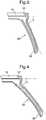
- the angle ⁇varies along the length of the seal strip, as illustrated by Figure 3 (approximately at mid-chord) and Figure 4 (close to the trailing edge).
- This varying shapeallows the seal to conform to the fan blade shape during build and during all running conditions, ensuring a good sealing between the blade and the seal and also ensuring that the filler is built centrally between the fan blades.
- By varying the anglethe size of the channel between the seal and the fan blade is minimised, thus maximising the aerodynamic efficiency of the assembly.
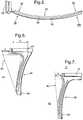
- the position of the seal strip relative to the side facevaries along the length of the seal strip. This is shown in Figures 5, 6 and 7 .
- the bonding platform 54is bonded in use to the annulus filler lid 14.
- the flap 38 of the seal stripprojects from the bonding platform 54.
- An additional seal portion 58is bonded in use beneath the leading edge of the annulus filler lid 14, and provides a seal between the annulus filler 12 and the spinner fairing (not shown).
- the varying position of the flap 38 relative to the bonding platform 54is clearly visible in Figure 5 .
- the arrows VI-VI and VII-VIIindicate the positions of the cross-sectional views of Figures 6 and 7 , which show this variation in more detail.
- the dimension Dis relatively small towards the forward end of the seal strip 26 ( Figure 6 ), and relatively large towards its rearward end ( Figure 7 ).
- This arrangementhas the further advantage that the gap E between the side face 22 of the annulus filler 12 and the surface 40 of the adjacent blade 42 is substantially constant, and relatively small. A large gap E would increase the risk of misalignment of the annulus filler 12 on assembly.
- the sealscan be used to guide the filler into position between the fan blades during build, and to ensure that it locates in the correct position between the two blades.
- the stiffness of the suction side seal strip 26is designed to be slightly higher than the stiffness of the pressure side seal strip 28.
- seal strip 26may be mounted on the annulus filler 12 by mechanical fasteners or by any other convenient method.
- the body 32 of the seal strip 26may be formed of any suitable resilient material.
- the stiffener 36may be coated on one side only with resilient material, instead of being embedded in it.
- the seal stripsmay be formed in composite material, incorporating an integral stiffener.
- the seal stripmay form an integral part of a larger composite component.
- the stiffener 36may be formed of a suitable non-metallic material. It may be formed in a single piece, or in several segments along the length of the seal strip 26.
- Such applicationsmay include others in which the components are subjected to centrifugal loads, but may also include non-rotating structures such as the fan outlet guide vane stage of a gas turbine engine, in which the gaps between stationary vanes are bridged by infill panels which define the inner wall of a flow annulus.
Landscapes
- Engineering & Computer Science (AREA)
- Mechanical Engineering (AREA)
- General Engineering & Computer Science (AREA)
- Structures Of Non-Positive Displacement Pumps (AREA)
- Turbine Rotor Nozzle Sealing (AREA)
Description
- This invention relates to gas turbine engines. More specifically, it relates to seals for bridging gaps between adjacent aerofoils in rotor or stator stages of gas turbine engines. The invention is particularly suited to seals for annulus fillers in a fan stage of an engine, but it may equally well be applied in other parts of the engine.
- Conventionally a fan rotor stage in a gas turbine engine comprises a plurality of radially extending fan blades mounted on a disc. The blades are mounted on the disc by inserting the inner end of the blade in a correspondingly shaped retention groove in the outer face of the disc periphery. Annulus fillers bridge the spaces between adjacent blades to define the inner wall of an annular gas passage in which the fan rotor stage is located in use.
- It is known to provide a seal between the annulus fillers and the adjacent fan blades by providing resilient strips bonded to the annulus fillers adjacent the fan blades. The strips protrude so that they abut the adjacent fan blades and seal the gaps. This prevents air leaking past the inner wall of the annular gas passage.
- The gaps vary throughout the flight cycle as the fan blades undergo tangential, radial and axial movements caused by gas, thermal and centrifugal loadings, and the annulus fillers move radially under the influence of centrifugal loading.
- A large number of seal designs are known, including solid rubber seals, bellows seals, brush seals, compressible tube seals and composite seals with a rubber tip.
- For example, European patent application
EP1067274A1 discloses a seal with a radially inwardly inclined flange portion. The flange portion of the seal is in the form of rubber bellows which have a cavity therein. The seal is open at one end to allow air compressed by the rotor to pass into the cavity and inflate the seal. - Known seals have various disadvantages. For example, solid rubber seals are heavy, the rubber tips of the composite seals are prone to debonding, and bellows seals are prone to severe erosion because the bellows sits close to the airstream. All these types of seal, though, share the particular disadvantage that they can only span relatively small gaps and accommodate relatively small movements between the fan blades and the annulus fillers.
- With increasing fan diameter comes a larger range of movement of the blades, especially pronounced with the swept fan blades increasingly favoured for their superior aerodynamic performance, and necessarily the gaps between the fan blades and the annulus fillers is larger. In such fans, conventional seals cannot maintain a satisfactory seal over the whole operating envelope of the engine.
- If gaps open up between the seal and the blade, grit or other foreign matter may be trapped between the seal and the blade, resulting in scratching of the blade surface which may render it unserviceable.
EP 1067274 discloses a seal having rubber bellows which have a cavity therein. The seal is open at one end to allow air compressed by a rotor to pass into the cavity and inflate the seal. Inflation of the seal ensures that the gap between the edge of a wall member and a blade is filled.WO 93/22539 - It is an aim of this invention to provide a seal for a rotor or stator stage in a gas turbine that alleviates the aforementioned problems.
- The invention provides a stage for a gas turbine engine, an annulus filler and a seal strip for an annulus filler as set out in the claims.
- The invention will now be described, by way of example, with reference to the accompanying drawings in which:
Figure 1 is a perspective view of an annulus filler for a stage according to the invention;Figure 2 is an axial view of a seal strip for a stage according to the invention, showing details of its construction;Figures 3 and 4 are axial views of a seal strip for a stage according to the invention, showing the variation in angle along the length of the seal;Figure 5 is a plan view of a seal strip for a stage according to the invention; andFigures 6 and 7 are cross-sectional views ofFigure 3 , taken respectively at the positions marked VI-VI and VII-VII.- Referring first to
Figure 1 , an annulus filler of known type is shown generally at 12. In use, theupper surface 14 or lid of theannulus filler 12 bridges the gap between two adjacent fan blades and defines the inner wall of the flow annulus of the fan stage. Theannulus filler 12 is mounted on a fan disc (not shown) by twohooks annulus filler 12. It is also attached to the support ring (not shown) by amounting feature 20. - The
annulus filler 12 has twoopposed side faces side face 22 confronts the suction surface of one fan blade, and theside face 24 confronts the pressure surface of the adjacent fan blade. Mounted adjacent theside face 22 is a suctionside seal strip 26, which extends generally outwards and downwards from the side face 22 (in use, these directions correspond respectively to circumferentially and radially inwards). A pressureside seal strip 28 is similarly mounted adjacent theside face 24. Figure 2 shows the construction of theseal strip 26 in more detail. The construction ofseal strip 28 is essentially identical.- The
seal strip 26 is adhesively mounted on the underside of theannulus filler lid 14, adjacent theside face 22. Thebody 32 of theseal strip 26 is formed of rubber, with acloth reinforcing layer 34. Theseal strip 26 also includes ametal stiffener 36, which extends substantially the full axial length of the seal strip 26 (in this figure, "axial" is the direction into and out of the paper). Theflap 38 defines an angle θ with theannulus filler lid 14. - The reinforcing
layer 34 extends through the whole radial depth of theseal strip 26. Thestiffener 36, however, does not. Dimension A indicates the distance from the top of thestiffener 36 to the top of theseal strip 26. Dimension B indicates the distance from the bottom of theseal strip 26 to the bottom of thestiffener 36. The radial depth of thestiffener 36 varies along its length to ensure that the dimensions A and B remain constant, so that the stiffener cannot break through therubber body 32 during manufacture. - In use, the
flap 38 of theseal strip 26 contacts thesuction surface 40 of afan blade 42. Centrifugal forces arising from the rotation of the fan stage urge theseal strip 26 into contact with thesurface 40, so that a close seal is maintained. The dimension D indicates the circumferential distance between theside face 22 and the top of thestiffener 36. The dimensions A and D are optimised to provide sufficient flexibility in theflap 38, while minimising the stresses in the adhesive joint between theseal strip 26 and the annulus filler. The dimensions A and D are also important to ensure that thestiffener 36 cannot migrate past theside face 22 and "knife" itself outwards, resulting in the loss of the seal. This "knifing" can occur if the stiffener is not supported sufficiently firmly. The centrifugal forces cause the stiffener to be forced outwards, and it may cut through the rubber and be released. - Dimension C shows the thickness of the rubber overlying the stiffener adjacent the aerofoil surface. This thickness must be sufficient to prevent the stiffener from breaking through and scratching the aerofoil surface.
- Large diameter, swept fan blades have a steep blade angle α from mid-chord rearwards to the trailing edge of the blade. If the seal strip presents the same angle to the blade surface along its whole length, there is a risk that part of the seal strip may become jammed against the blade during a run-down in speed, or conversely may "flip" through the gap between the annulus filler and the blade during a run-up in speed.
- To prevent this, the angle θ varies along the length of the seal strip, as illustrated by
Figure 3 (approximately at mid-chord) andFigure 4 (close to the trailing edge). This varying shape allows the seal to conform to the fan blade shape during build and during all running conditions, ensuring a good sealing between the blade and the seal and also ensuring that the filler is built centrally between the fan blades. By varying the angle the size of the channel between the seal and the fan blade is minimised, thus maximising the aerodynamic efficiency of the assembly. - Also, in contrast to known seals, the position of the seal strip relative to the side face varies along the length of the seal strip. This is shown in
Figures 5, 6 and 7 . InFigure 5 , thebonding platform 54 is bonded in use to theannulus filler lid 14. Theflap 38 of the seal strip projects from thebonding platform 54. Anadditional seal portion 58 is bonded in use beneath the leading edge of theannulus filler lid 14, and provides a seal between theannulus filler 12 and the spinner fairing (not shown). The varying position of theflap 38 relative to thebonding platform 54 is clearly visible inFigure 5 . The arrows VI-VI and VII-VII indicate the positions of the cross-sectional views ofFigures 6 and 7 , which show this variation in more detail. - The dimension D is relatively small towards the forward end of the seal strip 26 (
Figure 6 ), and relatively large towards its rearward end (Figure 7 ). This arrangement has the further advantage that the gap E between theside face 22 of theannulus filler 12 and thesurface 40 of theadjacent blade 42 is substantially constant, and relatively small. A large gap E would increase the risk of misalignment of theannulus filler 12 on assembly. - By tuning the relative stiffness of the pressure and suction side seals, the seals can be used to guide the filler into position between the fan blades during build, and to ensure that it locates in the correct position between the two blades. In this embodiment, the stiffness of the suction
side seal strip 26 is designed to be slightly higher than the stiffness of the pressureside seal strip 28. - It will be appreciated that various modifications are possible to the embodiment described in this specification, without departing from the spirit and scope of the claimed invention.
- For example, the
seal strip 26 may be mounted on theannulus filler 12 by mechanical fasteners or by any other convenient method. - The
body 32 of theseal strip 26 may be formed of any suitable resilient material. To suit certain manufacturing methods, thestiffener 36 may be coated on one side only with resilient material, instead of being embedded in it. - The seal strips may be formed in composite material, incorporating an integral stiffener. The seal strip may form an integral part of a larger composite component.
Thestiffener 36 may be formed of a suitable non-metallic material. It may be formed in a single piece, or in several segments along the length of theseal strip 26.
Although the invention is particularly suited to use in annulus fillers of fan stages, it could equally well be applied to any other application in which a varying gap has to be sealed. Such applications may include others in which the components are subjected to centrifugal loads, but may also include non-rotating structures such as the fan outlet guide vane stage of a gas turbine engine, in which the gaps between stationary vanes are bridged by infill panels which define the inner wall of a flow annulus.
Claims (16)
- An annulus filler (12) for bridging in use the space between two adjacent aerofoils of a gas turbine engine to define an inner wall of a flow annulus through the stage, the annulus filler having opposite side faces (22, 24) and an annulus filler lid (14), resilient seal strips (26, 28) each including a stiffener (36) being mounted adjacent the opposite side faces of the annulus filler, wherein:the resilient seal strips comprise a bonding platform (54) bonded to the annulus filler lid and a flap (38) projecting from the bonding platform, the flap being arranged to contact a pressure surface or a suction surface of a respective aerofoil in use;the position of the flap relative to the bonding platform varies along the length of each seal strip; andthe stiffener has three-dimensional curvature.
- An annulus filler as in claim 1, arranged such that, in use, a gap (E) between each side face of the annulus filler and the surface of the respective adjacent blade is substantially constant along its length.
- An annulus filler as in claim 1 or claim 2, in which in use the annulus filler bridges a space between a suction surface of one aerofoil and a pressure surface of an adjacent aerofoil, and in which the seal strip (26) adjacent the suction surface in use is stiffer than the seal strip (28) adjacent the pressure surface in use.
- An annulus filler as in claim 1 or claim 2, in which in use the annulus filler bridges a space between a suction surface of one aerofoil and a pressure surface of an adjacent aerofoil, and in which the seal strip (28) adjacent the pressure surface in use is stiffer than the seal strip (26) adjacent the suction surface in use.
- An annulus filler as in any of claims 1 to 4, in which each seal strip is mounted adjacent the respective side face of the annulus filler so as to define an angle between the seal strip and the respective side face, and in which the angle for at least one seal strip varies along the length of that seal strip.
- An annulus filler as in any of claims 1 to 5, in which the depth of at least one stiffener varies along the length of its associated seal strip.
- An annulus filler as in claim 6, in which the depth varies such that the distances from the bottom of the seal strip to the bottom of the stiffener, and from the top of the stiffener to the top of the seal strip, are constant along the length of the seal strip.
- An annulus filler as in any of claims 1 to 7, in which the seal strips are adhesively mounted adjacent the opposite side faces of the annulus filler.
- An annulus filler as in any preceding claim, in which each stiffener is coated in resilient material only on the side adjacent its respective aerofoil.
- An annulus filler as in any of claims 1 to 9, in which each stiffener is completely embedded in resilient material.
- An annulus filler as in claim 10, in which the resilient material is rubber.
- An annulus filler as in any of claims 1 to 11, in which the stiffener is manufactured as an integral part of a composite seal strip.
- An annulus filler as in any of claims 1 to 12, in which the seal strips are manufactured as an integral part of a composite component.
- A stage for a gas turbine engine comprising a plurality of circumferentially spaced apart radially extending aerofoils, and a plurality of annulus fillers according to any one of claims 1 to 13 provided to bridge the spaces between adjacent aerofoils to define an inner wall of a flow annulus through the stage, wherein the opposite side faces of each annulus filler are spaced circumferentially from the adjacent aerofoils and correspond in profile therewith.
- A stage according to claim 14, in which the aerofoils are stator vanes.
- A stage according to claim 14, in which the aerofoils are rotor blades.
Applications Claiming Priority (1)
| Application Number | Priority Date | Filing Date | Title |
|---|---|---|---|
| GBGB0611031.6AGB0611031D0 (en) | 2006-06-06 | 2006-06-06 | An aerofoil stage and a seal for use therein |
Publications (2)
| Publication Number | Publication Date |
|---|---|
| EP1865154A1 EP1865154A1 (en) | 2007-12-12 |
| EP1865154B1true EP1865154B1 (en) | 2017-03-15 |
Family
ID=36694936
Family Applications (1)
| Application Number | Title | Priority Date | Filing Date |
|---|---|---|---|
| EP07251926.7ACeasedEP1865154B1 (en) | 2006-06-06 | 2007-05-10 | Aerofoil stage and a seal for bridging gaps between adjacent airfoils |
Country Status (3)
| Country | Link |
|---|---|
| US (1) | US7950900B2 (en) |
| EP (1) | EP1865154B1 (en) |
| GB (1) | GB0611031D0 (en) |
Cited By (1)
| Publication number | Priority date | Publication date | Assignee | Title |
|---|---|---|---|---|
| US12012857B2 (en) | 2022-10-14 | 2024-06-18 | Rtx Corporation | Platform for an airfoil of a gas turbine engine |
Families Citing this family (27)
| Publication number | Priority date | Publication date | Assignee | Title |
|---|---|---|---|---|
| GB0804260D0 (en)* | 2008-03-07 | 2008-04-16 | Rolls Royce Plc | Annulus filler |
| FR2939836B1 (en)* | 2008-12-12 | 2015-05-15 | Snecma | SEAL FOR PLATFORM SEAL IN A TURBOMACHINE ROTOR |
| FR2939835B1 (en) | 2008-12-12 | 2017-06-09 | Snecma | PLATFORM SEAL SEAL IN A TURBOMACHINE ROTOR, METHOD FOR IMPROVING SEAL BETWEEN A PLATFORM AND A TURBOMACHINE BLADE. |
| EP2312125A1 (en)* | 2009-10-16 | 2011-04-20 | General Electric Company | Fairing seal |
| EP2447476A3 (en) | 2010-11-01 | 2017-11-15 | Rolls-Royce plc | Annulus filler for a rotor disk of a gas turbine |
| GB2484988B (en)* | 2010-11-01 | 2013-08-14 | Rolls Royce Plc | Annulus filler |
| GB201020857D0 (en) | 2010-12-09 | 2011-01-26 | Rolls Royce Plc | Annulus filler |
| FR2972482B1 (en)* | 2011-03-07 | 2016-07-29 | Snecma | TURBINE STAGE FOR AIRCRAFT TURBOMACHINE HAVING IMPROVED SEAL BETWEEN THE FLASK DOWN AND THE TURBINE BLADES BY MECHANICAL RETENTION |
| GB2490858B (en) | 2011-03-22 | 2014-01-01 | Rolls Royce Plc | A bladed rotor |
| FR2987086B1 (en)* | 2012-02-22 | 2014-03-21 | Snecma | LINEAR JOINT OF PLATFORM INTER-AUBES |
| FR2992676B1 (en)* | 2012-06-29 | 2014-08-01 | Snecma | INTER-AUBES PLATFORM FOR A BLOWER, BLOWER ROTOR AND METHOD OF MANUFACTURING THE SAME |
| US10344601B2 (en) | 2012-08-17 | 2019-07-09 | United Technologies Corporation | Contoured flowpath surface |
| US9297268B2 (en) | 2012-09-06 | 2016-03-29 | United Technologies Corporation | Fan blade platform flap seal |
| US9845699B2 (en)* | 2013-03-15 | 2017-12-19 | Gkn Aerospace Services Structures Corp. | Fan spacer having unitary over molded feature |
| US10145268B2 (en)* | 2013-03-15 | 2018-12-04 | United Technologies Corporation | Injection molded composite fan platform |
| US10280779B2 (en) | 2013-09-10 | 2019-05-07 | United Technologies Corporation | Plug seal for gas turbine engine |
| EP3068997B1 (en) | 2013-11-11 | 2021-12-29 | Raytheon Technologies Corporation | Segmented seal for gas turbine engine |
| EP3080418B1 (en)* | 2013-12-13 | 2020-06-24 | United Technologies Corporation | Fan platform edge seal |
| GB201400756D0 (en)* | 2014-01-16 | 2014-03-05 | Rolls Royce Plc | Blisk |
| EP3183429A1 (en)* | 2014-08-22 | 2017-06-28 | Siemens Energy, Inc. | Modular turbine blade with separate platform support system |
| FR3037097B1 (en)* | 2015-06-03 | 2017-06-23 | Snecma | COMPOSITE AUBE COMPRISING A PLATFORM WITH A STIFFENER |
| US10634055B2 (en) | 2015-02-05 | 2020-04-28 | United Technologies Corporation | Gas turbine engine having section with thermally isolated area |
| US9920652B2 (en) | 2015-02-09 | 2018-03-20 | United Technologies Corporation | Gas turbine engine having section with thermally isolated area |
| US11028714B2 (en)* | 2018-07-16 | 2021-06-08 | Raytheon Technologies Corporation | Fan platform wedge seal |
| FR3091563B1 (en)* | 2019-01-04 | 2023-01-20 | Safran Aircraft Engines | Improved inter-blade platform seal |
| FR3097909B1 (en)* | 2019-06-27 | 2021-09-17 | Safran Aircraft Engines | Internal ferrule of an intermediate casing, associated intermediate casing with lamellae forming shock absorbers |
| US11268397B2 (en)* | 2020-02-07 | 2022-03-08 | Raytheon Technologies Corporation | Fan blade platform seal and method for forming same |
Family Cites Families (9)
| Publication number | Priority date | Publication date | Assignee | Title |
|---|---|---|---|---|
| GB9209895D0 (en)* | 1992-05-07 | 1992-06-24 | Rolls Royce Plc | Rotors for gas turbine engines |
| JP3684620B2 (en) | 1995-06-19 | 2005-08-17 | 石川島播磨重工業株式会社 | Interblade spacer seal structure |
| GB9602129D0 (en)* | 1996-02-02 | 1996-04-03 | Rolls Royce Plc | Rotors for gas turbine engines |
| US5820338A (en) | 1997-04-24 | 1998-10-13 | United Technologies Corporation | Fan blade interplatform seal |
| GB9828484D0 (en) | 1998-12-24 | 1999-02-17 | Rolls Royce Plc | Improvements in or relating to bladed structures for fluid flow propulsion engines |
| US6217283B1 (en)* | 1999-04-20 | 2001-04-17 | General Electric Company | Composite fan platform |
| GB9915637D0 (en)* | 1999-07-06 | 1999-09-01 | Rolls Royce Plc | A rotor seal |
| US6634863B1 (en)* | 2000-11-27 | 2003-10-21 | General Electric Company | Circular arc multi-bore fan disk assembly |
| US7121800B2 (en) | 2004-09-13 | 2006-10-17 | United Technologies Corporation | Turbine blade nested seal damper assembly |
- 2006
- 2006-06-06GBGBGB0611031.6Apatent/GB0611031D0/ennot_activeCeased
- 2007
- 2007-05-10EPEP07251926.7Apatent/EP1865154B1/ennot_activeCeased
- 2007-05-11USUS11/798,252patent/US7950900B2/enactiveActive
Non-Patent Citations (1)
| Title |
|---|
| None* |
Cited By (1)
| Publication number | Priority date | Publication date | Assignee | Title |
|---|---|---|---|---|
| US12012857B2 (en) | 2022-10-14 | 2024-06-18 | Rtx Corporation | Platform for an airfoil of a gas turbine engine |
Also Published As
| Publication number | Publication date |
|---|---|
| GB0611031D0 (en) | 2006-07-12 |
| US20070280830A1 (en) | 2007-12-06 |
| EP1865154A1 (en) | 2007-12-12 |
| US7950900B2 (en) | 2011-05-31 |
Similar Documents
| Publication | Publication Date | Title |
|---|---|---|
| EP1865154B1 (en) | Aerofoil stage and a seal for bridging gaps between adjacent airfoils | |
| EP0787890B1 (en) | Rotors for gas turbine engines | |
| JP4098395B2 (en) | Fan blade interplatform seal | |
| EP1741878B1 (en) | Fluid flow machine | |
| JP3628328B2 (en) | Compressor stator assembly | |
| JP5394006B2 (en) | Method for protecting airfoils and leading edges of airfoils | |
| EP3473811B1 (en) | Fan blade platform | |
| US10344601B2 (en) | Contoured flowpath surface | |
| US6340286B1 (en) | Rotary machine having a seal assembly | |
| US9297268B2 (en) | Fan blade platform flap seal | |
| EP2270314B1 (en) | An assembly providing contaminant removal | |
| US20140308133A1 (en) | Rotor wheel for a turbine engine | |
| US9017032B2 (en) | Bladed rotor | |
| US20040012151A1 (en) | Sealing arrangement | |
| EP1881159B1 (en) | A fan blade for a gas turbine engine | |
| US10895159B2 (en) | Removable anti-wear part for blade tip | |
| US8540487B2 (en) | Actuatable seal for aerofoil blade tip | |
| US7097428B2 (en) | Integral cover bucket design | |
| CN102654141A (en) | Segmented shroud assembly suitable for compensating a rotor misalignment relative to the stator | |
| EP3486496B1 (en) | Fan for gas turbine engines having mid-span shroud | |
| EP3048260B1 (en) | Seal for turbofan engine | |
| EP2935790B1 (en) | Composite aerofoil structure with a cutting edge tip portion | |
| US11326461B2 (en) | Hybrid rubber grommet for potted stator | |
| EP4556685A1 (en) | Multi-material abradable shroud for gas turbine engine rotor |
Legal Events
| Date | Code | Title | Description |
|---|---|---|---|
| PUAI | Public reference made under article 153(3) epc to a published international application that has entered the european phase | Free format text:ORIGINAL CODE: 0009012 | |
| AK | Designated contracting states | Kind code of ref document:A1 Designated state(s):AT BE BG CH CY CZ DE DK EE ES FI FR GB GR HU IE IS IT LI LT LU LV MC MT NL PL PT RO SE SI SK TR | |
| AX | Request for extension of the european patent | Extension state:AL BA HR MK YU | |
| 17P | Request for examination filed | Effective date:20071115 | |
| 17Q | First examination report despatched | Effective date:20080116 | |
| AKX | Designation fees paid | Designated state(s):DE FR GB | |
| RAP1 | Party data changed (applicant data changed or rights of an application transferred) | Owner name:ROLLS-ROYCE PLC | |
| GRAP | Despatch of communication of intention to grant a patent | Free format text:ORIGINAL CODE: EPIDOSNIGR1 | |
| STAA | Information on the status of an ep patent application or granted ep patent | Free format text:STATUS: GRANT OF PATENT IS INTENDED | |
| INTG | Intention to grant announced | Effective date:20161207 | |
| GRAS | Grant fee paid | Free format text:ORIGINAL CODE: EPIDOSNIGR3 | |
| GRAA | (expected) grant | Free format text:ORIGINAL CODE: 0009210 | |
| STAA | Information on the status of an ep patent application or granted ep patent | Free format text:STATUS: THE PATENT HAS BEEN GRANTED | |
| AK | Designated contracting states | Kind code of ref document:B1 Designated state(s):DE FR GB | |
| REG | Reference to a national code | Ref country code:GB Ref legal event code:FG4D | |
| REG | Reference to a national code | Ref country code:DE Ref legal event code:R096 Ref document number:602007050166 Country of ref document:DE | |
| REG | Reference to a national code | Ref country code:FR Ref legal event code:PLFP Year of fee payment:11 | |
| REG | Reference to a national code | Ref country code:DE Ref legal event code:R097 Ref document number:602007050166 Country of ref document:DE | |
| PLBE | No opposition filed within time limit | Free format text:ORIGINAL CODE: 0009261 | |
| STAA | Information on the status of an ep patent application or granted ep patent | Free format text:STATUS: NO OPPOSITION FILED WITHIN TIME LIMIT | |
| 26N | No opposition filed | Effective date:20171218 | |
| REG | Reference to a national code | Ref country code:FR Ref legal event code:PLFP Year of fee payment:12 | |
| PGFP | Annual fee paid to national office [announced via postgrant information from national office to epo] | Ref country code:GB Payment date:20220524 Year of fee payment:16 Ref country code:FR Payment date:20220526 Year of fee payment:16 Ref country code:DE Payment date:20220527 Year of fee payment:16 | |
| P01 | Opt-out of the competence of the unified patent court (upc) registered | Effective date:20230528 | |
| REG | Reference to a national code | Ref country code:DE Ref legal event code:R119 Ref document number:602007050166 Country of ref document:DE | |
| GBPC | Gb: european patent ceased through non-payment of renewal fee | Effective date:20230510 | |
| PG25 | Lapsed in a contracting state [announced via postgrant information from national office to epo] | Ref country code:DE Free format text:LAPSE BECAUSE OF NON-PAYMENT OF DUE FEES Effective date:20231201 Ref country code:GB Free format text:LAPSE BECAUSE OF NON-PAYMENT OF DUE FEES Effective date:20230510 | |
| PG25 | Lapsed in a contracting state [announced via postgrant information from national office to epo] | Ref country code:FR Free format text:LAPSE BECAUSE OF NON-PAYMENT OF DUE FEES Effective date:20230531 |