EP1858243B1 - Barbed suture in combination with surgical needle - Google Patents
Barbed suture in combination with surgical needleDownload PDFInfo
- Publication number
- EP1858243B1 EP1858243B1EP07015906AEP07015906AEP1858243B1EP 1858243 B1EP1858243 B1EP 1858243B1EP 07015906 AEP07015906 AEP 07015906AEP 07015906 AEP07015906 AEP 07015906AEP 1858243 B1EP1858243 B1EP 1858243B1
- Authority
- EP
- European Patent Office
- Prior art keywords
- barbs
- suture
- barb
- barbed
- surgical needle
- Prior art date
- Legal status (The legal status is an assumption and is not a legal conclusion. Google has not performed a legal analysis and makes no representation as to the accuracy of the status listed.)
- Revoked
Links
- 230000033001locomotionEffects0.000claimsabstractdescription14
- 241001465754MetazoaSpecies0.000claimsabstractdescription9
- 210000001519tissueAnatomy0.000description98
- 238000005520cutting processMethods0.000description71
- 206010052428WoundDiseases0.000description42
- 208000027418Wounds and injuryDiseases0.000description42
- 238000005259measurementMethods0.000description40
- 238000003780insertionMethods0.000description35
- 230000037431insertionEffects0.000description35
- 229920002463poly(p-dioxanone) polymerPolymers0.000description21
- 239000000622polydioxanoneSubstances0.000description21
- 238000000034methodMethods0.000description15
- 239000000463materialSubstances0.000description14
- 230000000149penetrating effectEffects0.000description13
- 241001481789RupicapraSpecies0.000description10
- 229920000642polymerPolymers0.000description10
- 238000004873anchoringMethods0.000description9
- 238000012360testing methodMethods0.000description9
- 230000008901benefitEffects0.000description8
- 210000003491skinAnatomy0.000description8
- 241001517013Calidris pugnaxSpecies0.000description7
- 241000282472Canis lupus familiarisSpecies0.000description6
- 229920001577copolymerPolymers0.000description6
- 238000005304joiningMethods0.000description6
- 239000004677NylonSubstances0.000description5
- 241000700159RattusSpecies0.000description5
- 239000004744fabricSubstances0.000description5
- 229920001778nylonPolymers0.000description5
- -1silkSubstances0.000description5
- 239000010985leatherSubstances0.000description4
- 238000010561standard procedureMethods0.000description4
- AEMRFAOFKBGASW-UHFFFAOYSA-NGlycolic acidChemical compoundOCC(O)=OAEMRFAOFKBGASW-UHFFFAOYSA-N0.000description3
- 239000011248coating agentSubstances0.000description3
- 238000000576coating methodMethods0.000description3
- 230000007423decreaseEffects0.000description3
- 229910003460diamondInorganic materials0.000description3
- 239000010432diamondSubstances0.000description3
- 238000001125extrusionMethods0.000description3
- 238000001727in vivoMethods0.000description3
- 238000012986modificationMethods0.000description3
- 230000004048modificationEffects0.000description3
- 210000003205muscleAnatomy0.000description3
- 210000004872soft tissueAnatomy0.000description3
- RKDVKSZUMVYZHH-UHFFFAOYSA-N1,4-dioxane-2,5-dioneChemical compoundO=C1COC(=O)CO1RKDVKSZUMVYZHH-UHFFFAOYSA-N0.000description2
- 229920000742CottonPolymers0.000description2
- XZMCDFZZKTWFGF-UHFFFAOYSA-NCyanamideChemical compoundNC#NXZMCDFZZKTWFGF-UHFFFAOYSA-N0.000description2
- 239000004743PolypropyleneSubstances0.000description2
- 239000002251absorbable suture materialSubstances0.000description2
- 238000007792additionMethods0.000description2
- 230000015572biosynthetic processEffects0.000description2
- 210000004204blood vesselAnatomy0.000description2
- WERYXYBDKMZEQL-UHFFFAOYSA-Nbutane-1,4-diolChemical compoundOCCCCOWERYXYBDKMZEQL-UHFFFAOYSA-N0.000description2
- 230000023753dehiscenceEffects0.000description2
- 229920000295expanded polytetrafluoroethylenePolymers0.000description2
- 239000000835fiberSubstances0.000description2
- JVTAAEKCZFNVCJ-UHFFFAOYSA-Nlactic acidChemical compoundCC(O)C(O)=OJVTAAEKCZFNVCJ-UHFFFAOYSA-N0.000description2
- 230000014759maintenance of locationEffects0.000description2
- 238000004519manufacturing processMethods0.000description2
- 210000005036nerveAnatomy0.000description2
- 230000035515penetrationEffects0.000description2
- 229920000728polyesterPolymers0.000description2
- 229920001155polypropylenePolymers0.000description2
- 230000037390scarringEffects0.000description2
- 238000001356surgical procedureMethods0.000description2
- 210000002435tendonAnatomy0.000description2
- MFRCZYUUKMFJQJ-UHFFFAOYSA-N1,4-dioxane-2,5-dione;1,3-dioxan-2-oneChemical compoundO=C1OCCCO1.O=C1COC(=O)CO1MFRCZYUUKMFJQJ-UHFFFAOYSA-N0.000description1
- 102000008186CollagenHuman genes0.000description1
- 108010035532CollagenProteins0.000description1
- 206010015548EuthanasiaDiseases0.000description1
- 229920000544Gore-TexPolymers0.000description1
- 206010022524Intentional self-injuryDiseases0.000description1
- 208000034693LacerationDiseases0.000description1
- 239000004952PolyamideSubstances0.000description1
- 239000004698PolyethyleneSubstances0.000description1
- 229920000954PolyglycolidePolymers0.000description1
- 208000005560Self MutilationDiseases0.000description1
- 229910000831SteelInorganic materials0.000description1
- 208000002847Surgical WoundDiseases0.000description1
- 230000001154acute effectEffects0.000description1
- 239000000853adhesiveSubstances0.000description1
- 230000001070adhesive effectEffects0.000description1
- 229920005603alternating copolymerPolymers0.000description1
- 238000013459approachMethods0.000description1
- 230000000712assemblyEffects0.000description1
- 238000000429assemblyMethods0.000description1
- 230000009286beneficial effectEffects0.000description1
- 229920001400block copolymerPolymers0.000description1
- 210000000988bone and boneAnatomy0.000description1
- 230000015556catabolic processEffects0.000description1
- 210000000038chestAnatomy0.000description1
- 229920001436collagenPolymers0.000description1
- 230000000295complement effectEffects0.000description1
- 239000007799corkSubstances0.000description1
- 238000002316cosmetic surgeryMethods0.000description1
- 238000002788crimpingMethods0.000description1
- 230000003247decreasing effectEffects0.000description1
- 238000006731degradation reactionMethods0.000description1
- 210000004207dermisAnatomy0.000description1
- 125000000118dimethyl groupChemical group[H]C([H])([H])*0.000description1
- 238000005553drillingMethods0.000description1
- 230000000694effectsEffects0.000description1
- 238000002674endoscopic surgeryMethods0.000description1
- 210000003195fasciaAnatomy0.000description1
- 229920000578graft copolymerPolymers0.000description1
- 230000035876healingEffects0.000description1
- 229920001519homopolymerPolymers0.000description1
- 238000003384imaging methodMethods0.000description1
- 238000001746injection mouldingMethods0.000description1
- 235000014655lactic acidNutrition0.000description1
- 239000004310lactic acidSubstances0.000description1
- 210000003041ligamentAnatomy0.000description1
- 239000002184metalSubstances0.000description1
- 229910001092metal group alloyInorganic materials0.000description1
- 238000002406microsurgeryMethods0.000description1
- 239000000203mixtureSubstances0.000description1
- 238000005457optimizationMethods0.000description1
- 210000000056organAnatomy0.000description1
- 238000012856packingMethods0.000description1
- 238000011056performance testMethods0.000description1
- 210000004303peritoneumAnatomy0.000description1
- 229920000747poly(lactic acid)Polymers0.000description1
- 229920002647polyamidePolymers0.000description1
- 229920001610polycaprolactonePolymers0.000description1
- 239000004632polycaprolactoneSubstances0.000description1
- 238000012643polycondensation polymerizationMethods0.000description1
- 229920000573polyethylenePolymers0.000description1
- 229920001343polytetrafluoroethylenePolymers0.000description1
- 239000004810polytetrafluoroethyleneSubstances0.000description1
- 229920000909polytetrahydrofuranPolymers0.000description1
- 229920002635polyurethanePolymers0.000description1
- 239000004814polyurethaneSubstances0.000description1
- 230000001737promoting effectEffects0.000description1
- 229920005604random copolymerPolymers0.000description1
- 238000000926separation methodMethods0.000description1
- 238000009958sewingMethods0.000description1
- 229920002050silicone resinPolymers0.000description1
- 238000012453sprague-dawley rat modelMethods0.000description1
- 239000010959steelSubstances0.000description1
- 229920001897terpolymerPolymers0.000description1
- 230000000699topical effectEffects0.000description1
- YFHICDDUDORKJB-UHFFFAOYSA-Ntrimethylene carbonateChemical compoundO=C1OCCCO1YFHICDDUDORKJB-UHFFFAOYSA-N0.000description1
- 210000000689upper legAnatomy0.000description1
- 210000001835visceraAnatomy0.000description1
- 230000029663wound healingEffects0.000description1
- PAPBSGBWRJIAAV-UHFFFAOYSA-Nε-CaprolactoneChemical compoundO=C1CCCCCO1PAPBSGBWRJIAAV-UHFFFAOYSA-N0.000description1
Images


Classifications
- A—HUMAN NECESSITIES
- A61—MEDICAL OR VETERINARY SCIENCE; HYGIENE
- A61L—METHODS OR APPARATUS FOR STERILISING MATERIALS OR OBJECTS IN GENERAL; DISINFECTION, STERILISATION OR DEODORISATION OF AIR; CHEMICAL ASPECTS OF BANDAGES, DRESSINGS, ABSORBENT PADS OR SURGICAL ARTICLES; MATERIALS FOR BANDAGES, DRESSINGS, ABSORBENT PADS OR SURGICAL ARTICLES
- A61L17/00—Materials for surgical sutures or for ligaturing blood vessels ; Materials for prostheses or catheters
- A61L17/06—At least partially resorbable materials
- A61L17/10—At least partially resorbable materials containing macromolecular materials
- A—HUMAN NECESSITIES
- A61—MEDICAL OR VETERINARY SCIENCE; HYGIENE
- A61B—DIAGNOSIS; SURGERY; IDENTIFICATION
- A61B17/00—Surgical instruments, devices or methods
- A61B17/04—Surgical instruments, devices or methods for suturing wounds; Holders or packages for needles or suture materials
- A—HUMAN NECESSITIES
- A61—MEDICAL OR VETERINARY SCIENCE; HYGIENE
- A61B—DIAGNOSIS; SURGERY; IDENTIFICATION
- A61B17/00—Surgical instruments, devices or methods
- A61B17/04—Surgical instruments, devices or methods for suturing wounds; Holders or packages for needles or suture materials
- A61B17/06—Needles ; Sutures; Needle-suture combinations; Holders or packages for needles or suture materials
- A61B17/06166—Sutures
- A—HUMAN NECESSITIES
- A61—MEDICAL OR VETERINARY SCIENCE; HYGIENE
- A61L—METHODS OR APPARATUS FOR STERILISING MATERIALS OR OBJECTS IN GENERAL; DISINFECTION, STERILISATION OR DEODORISATION OF AIR; CHEMICAL ASPECTS OF BANDAGES, DRESSINGS, ABSORBENT PADS OR SURGICAL ARTICLES; MATERIALS FOR BANDAGES, DRESSINGS, ABSORBENT PADS OR SURGICAL ARTICLES
- A61L17/00—Materials for surgical sutures or for ligaturing blood vessels ; Materials for prostheses or catheters
- A61L17/04—Non-resorbable materials
- A—HUMAN NECESSITIES
- A61—MEDICAL OR VETERINARY SCIENCE; HYGIENE
- A61L—METHODS OR APPARATUS FOR STERILISING MATERIALS OR OBJECTS IN GENERAL; DISINFECTION, STERILISATION OR DEODORISATION OF AIR; CHEMICAL ASPECTS OF BANDAGES, DRESSINGS, ABSORBENT PADS OR SURGICAL ARTICLES; MATERIALS FOR BANDAGES, DRESSINGS, ABSORBENT PADS OR SURGICAL ARTICLES
- A61L31/00—Materials for other surgical articles, e.g. stents, stent-grafts, shunts, surgical drapes, guide wires, materials for adhesion prevention, occluding devices, surgical gloves, tissue fixation devices
- A61L31/08—Materials for coatings
- A61L31/10—Macromolecular materials
- A—HUMAN NECESSITIES
- A61—MEDICAL OR VETERINARY SCIENCE; HYGIENE
- A61B—DIAGNOSIS; SURGERY; IDENTIFICATION
- A61B17/00—Surgical instruments, devices or methods
- A61B17/04—Surgical instruments, devices or methods for suturing wounds; Holders or packages for needles or suture materials
- A61B17/06—Needles ; Sutures; Needle-suture combinations; Holders or packages for needles or suture materials
- A61B17/06004—Means for attaching suture to needle
- A61B2017/06028—Means for attaching suture to needle by means of a cylindrical longitudinal blind bore machined at the suture-receiving end of the needle, e.g. opposite to needle tip
- A—HUMAN NECESSITIES
- A61—MEDICAL OR VETERINARY SCIENCE; HYGIENE
- A61B—DIAGNOSIS; SURGERY; IDENTIFICATION
- A61B17/00—Surgical instruments, devices or methods
- A61B17/04—Surgical instruments, devices or methods for suturing wounds; Holders or packages for needles or suture materials
- A61B17/06—Needles ; Sutures; Needle-suture combinations; Holders or packages for needles or suture materials
- A61B2017/06057—Double-armed sutures, i.e. sutures having a needle attached to each end
- A—HUMAN NECESSITIES
- A61—MEDICAL OR VETERINARY SCIENCE; HYGIENE
- A61B—DIAGNOSIS; SURGERY; IDENTIFICATION
- A61B17/00—Surgical instruments, devices or methods
- A61B17/04—Surgical instruments, devices or methods for suturing wounds; Holders or packages for needles or suture materials
- A61B17/06—Needles ; Sutures; Needle-suture combinations; Holders or packages for needles or suture materials
- A61B17/06166—Sutures
- A61B2017/06176—Sutures with protrusions, e.g. barbs
Definitions
- This inventionrelates, in general, to a barbed suture useful for connecting bodily tissue in various surgical contexts, and more particularly, to the optimization of the disposition and/or configuration of the barbs on such barbed sutures.
- sutureshave been used in the past for closing or binding together wounds in human or animal tissue, such as skin, muscles, tendons, internal organs, nerves, blood vessels, and the like. More specifically, the surgeon may use a surgical needle with an attached conventional suture (which can be a smooth monofilament or can be a multi-filament) to pierce the tissue alternately on opposing faces of the wound and thus sew the wound closed. Whether the wound is accidental or surgical, loop stitching is the method often used, especially for surface wounds. The surgical needle is then removed and the ends of the suture are tied, typically with at least three overhand throws to form a knot.
- conventional suturewhich can be a smooth monofilament or can be a multi-filament
- conventional suturescan be of non-absorbable material such as silk, nylon, polyester, polypropylene, or cotton, or can be of bio-absorbable material such as glycolic acid polymers and copolymers or lactic acid polymers and copolymers.
- a barbed sutureincludes an elongated body that has one or more spaced barbs, which project from the body surface along the body length. The barbs are arranged to allow passage of the barbed suture in one direction through tissue but resist movement of the barbed suture in the opposite direction.
- the main advantage of barbed sutureshas been the provision of a non-slip attribute. Accordingly, barbed sutures do not have to be knotted, like conventional sutures.
- a barbed suturemay be inserted into tissue using a surgical needle.
- U.S. Patent No. 3,123,077 to Alcamodescribes an elongated cord for sewing human flesh, where the cord has a body portion and sharp-edged, resilient barbs projecting from the body at acute angles relative to the body.
- the barbed suturecan be passed through tissue in one direction, but resists movement in the opposite direction.
- Sutures with barbs disposed in a bi-directional arrangementare shown in U.S. Patent No. 5,931,855 to Buncke and U.S. Patent No. 6,241,747 to Ruff . More particularly, the suture has barbs facing toward one end of the suture for about half the suture length and barbs facing in the opposite direction toward the other end of the suture for the other half of the suture length. This arrangement allows the barbs to move in the same direction as each respective suture end is inserted into the first and second sides of a wound.
- Such bi-directional barbed suturesnot only are especially suitable for closing wounds with edges prone to separation, but also obviate the need to secure suture ends together with knotted loops.
- U.S. Patent No. 5,342,376 to Ruffshows an insertion device that is useful for positioning a barbed suture in order to close a wound.
- the insertion devicehas a tubular body for receiving a barbed suture, and preferably also has a handle to facilitate manipulation of the device by the surgeon.
- the insertion deviceis recommended for use with a barbed suture where the suture portion being inserted includes barbs facing a direction opposed to the direction of insertion. Such sutures with barbs opposing the direction of insertion are also shown in '376 to Ruff.
- Escarpment of barbs into a monofilamentreduces the straight pull tensile strength since the effective suture diameter is decreased.
- the straight pull tensile strength of a barbed sutureshould be compared to the minimum knot pull strength of a conventional suture (a non-barbed suture) in accordance with the United States Pharmacopoeia since failure of conventional sutures (which have to be knotted and must meet a minimum knot pull tensile strength) occurs most frequently at the knot due to increased local stress.
- barbed sutureTo optimize the performance of a barbed suture, it is advantageous to consider varying the barb geometry (barb cut angle, barb cut depth, barb cut length, barb cut distance, etc.) and/or the spatial arrangement of the barbs. This should not only enhance the tensile strength of a barbed suture, but also should enhance the ability of a barbed suture in holding and maintaining wound edges together. Unlike conventional sutures, which place tensions directly at the knots, barbed sutures can spread out the tension along the escarped suture length, often evenly along the length. Optimizing the disposition and/or the configuration of the barbs should therefore further increase the effectiveness of the new barbed suture in maximizing the holding strength and minimizing the gap formation along the wound edges. The latter is particularly beneficial for promoting wound healing.
- new barbed suturesshould approximate tissue quickly with appropriate tension, alleviate distortion of tissue, and help to minimize scarring, due to the self-retaining benefits imparted by the barbs.
- the new barbed sutureswould be especially useful in surgeries where minimization of scarring is imperative, such as cosmetic surgery, as well as in surgeries where space is limited, such as endoscopic surgery or microsurgery.
- the present inventionprovides a barbed suture for connecting human or animal tissue in combination with a surgical needle.
- Said combinationcomprises a barbed suture attached to a surgical needle, wherein the suture comprises a plurality of barbs projecting from an elongated body having a first end and a second end and a diameter. Each barb faces in a direction and is adapted for resisting movement of the suture when in tissue, in an opposite direction from the direction in which the barb faces.
- the elongated bodyhas a non-circular cross-sectional shape and the surgical needle has a diameter with a ratio of the surgical needle diameter to the barbed suture diameter of between about 3:1 and 1.47:1.
- non-circular cross sectional shapeis chosen from oval, triangle, square, parallelogram, trapezoid, rhomboid, pentagon, hexagon, or cruciform.
- the elongated bodymay have the barbs having a barb cut angle ⁇ ranging from about 140° to about 175°.
- the elongated bodymay have the barbs having a barb cut depth D with a ratio of the barb cut depth D to the barbed suture diameter ranging from about 0.05 to about 0.6.
- the elongated bodyhas the barbs having a barb cut depth L with a ratio of the barb cut length L to the barbed suture diameter ranging from about 0.2 to about 2.
- the elongated bodycould have the barbs having a barb cut distance P with a ratio of the barb cut distance P to the barbed suture diameter ranging from about 0.1 to about 6.
- the elongated bodymay have the barbs having a corrugated barb underside.
- the elongated bodyhas the barbs having an arcuate base were the barbs are attached to the elongated body.
- the elongated bodymay have the barbs having at least two sets of barbs with each set having a barb size different from the barb size of the other set.
- the elongated bodycould have the barbs in a staggered disposition on the elongated body.
- the elongated bodyhas the barbs in a staggered disposition on the elongated body and the staggered position, has a plurality of axially spaced barbs radially arranged about 180° from and staggered with respect to an other plurality of axially spaced barbs or has a plurality of axially spaced barbs radially arranged about 120° from and staggered with respect to a first other plurality of axially spaced barbs which are radially arranged about 120° from and staggered with respect to a second other plurality of axially spaced barbs.
- the elongated bodymay have the barbs in a staggered disposition on the elongated body and the staggered disposition has a plurality of axially spaced barbs radially arranged about 120° from and staggered with respect to a first other plurality of axially spaced barbs which are radially arranged about 120° from and staggered with respect to a second other plurality of axially spaced barbs and the elongated body may have a non-circular cross sectional shape chosen from triangle.
- the elongated bodyhas the barbs arranged in a uni-directional disposition or in a bi-directional disposition.
- woundmeans a surgical incision, cut, laceration, severed tissue or accidental wound in human or animal skin or other human or animal bodily tissue, or other condition in a human or animal where suturing, stapling, or the use of another tissue connecting device may be required.
- tissueincludes, but is not limited to, tissues such as skin, fat, fascia, bone, muscle, organs, nerves, or blood vessels, or fibrous tissues such as tendons or ligaments.
- polymeras used here generally includes, but is not limited to, homopolymers, copolymers (such as block, graft, random and alternating copolymers), terpolymers, et cetera, and blends and modifications thereof.
- polymershall include all possible structures of the material. These structures include, but are not limited to, isotactic, syndiotactic, and random symmetries.
- the suturesare described below in a preferred embodiment with a circular cross section, the sutures according to the present invention have a non-circular cross sectional shape that increases the surface area and facilitates the formation of the barbs.
- Cross sectional shapesmay include, but are not limited to, oval, triangle, square, parallelogram, trapezoid, rhomboid, pentagon, hexagon, cruciform, and the like.
- barbsare cut into a polymeric filament that has been formed by extrusion using a die with a circular cross section, and thus, the cross section of the filament will be circular, as that is what results during such extrusion.
- extrusion diescan be custom made with any desired cross-sectional shape.
- the term "diameter” as used hereis intended to mean the transverse length of the cross section, regardless of whether the cross section is circular or some other shape.
- Suitable diameters for the inventive sutures described belowmay range from about 0.001 mm to about 1 mm, and of course, the diameter may be from about 0.01 mm to about 0.9 mm, or from about 0.015 mm to about 0.8 mm. The typical diameter ranges from about 0.01 mm to about 0.5 mm.
- the length of the suturecan vary depending on several factors such as the length and/or depth of the wound to be closed, the type of tissue to be joined, the location of the wound, and the like. Typical suture lengths range from about 1 cm to about 30 cm, more particularly from about 2 cm to about 22 cm.
- staggered and staggeringas used here in relation to the disposition of barbs on a suture are intended to mean that the suture has at least two sets of barbs that are offset with respect to each other, where the first set is aligned longitudinally on the suture and the second set is aligned longitudinally on the suture, but a plane perpendicular to the suture and cutting transversely through the suture and intersecting the base of a barb of the first set will not intersect the base of a barb of the second set.
- barbsproject from the exterior surface of the suture body on which the barbs are disposed.
- barbs of different sizesmay be employed. In general, larger barbs are more suitable for joining certain types of tissue such as fat tissue or soft tissue. On the other hand, smaller barbs are more suitable for joining other types of tissue, such as collagen dense tissue.
- barbed suturesmay be made from the same materials used for making conventional loop sutures. Any particular chosen material for the barbed suture depends on the strength and flexibility requirements.
- barbed suturesmay be formed from a bio-absorbable material that allows the suture to degrade and thus to be absorbed over time into the tissue as the wound heals.
- bio-absorbable materialsare polymeric, and depending on the particular polymer selected, the degradation time in the wound ranges from about 1 month to over 24 months. The use of bio-absorbable materials eliminates the necessity of removing the sutures from the patient.
- bio-absorbable polymersinclude, but are not limited to, polydioxanone, polylactide, polyglycolide, polycaprolactone, and copolymers thereof.
- Commercially available examplesare polydioxanone (sold as PDS II, a trade name used by Ethicon for selling surgical sutures), copolymer of about 67% glycolide and about 33% trimethylene carbonate (sold as MAXON®, a trademark registered to American Cyanamid for surgical sutures), and copolymer of about 75% glycolide and about 25% caprolactone (sold as MONOCRYL®, a trademark registered to Johnson & Johnson for sutures and suture needles). Barbed sutures made from such bio-absorbable materials are useful in a wide range of applications.
- barbed suturesmay be formed from a non-absorbable material, which may be a polymer.
- polymersinclude, but are not limited to, polypropylene, polyamide (also known as nylon), polyester (such as polyethylene terephthlate, abbreviated here as PET), polytetrafluoroethylene (such as expanded polytetrafluoroethylene, abbreviated here as ePTFE and sold by Gore as GOR-TEX®), polyether-ester (such as polybutester, which is the condensation polymerization of dimethyl terephthlate, polytetramethylene ether glycol, and 1,4-butanediol, and which is marketed by Davis & Geck and by U.S.
- the non-absorbable materialmay be metal (e.g., steel), metal alloys, natural fiber (e.g., silk, cotton, et cetera), and the like.
- the ends of the barbed suturesmay comprise a surgical needle.
- the barbed sutureis adapted for attachment, such as by swaging, channel wrapping, heat shrinking, or eyelet threading to the surgical needle for insertion into tissue.
- Attachment by swagingis well described and is typically accomplished by inserting the suture end into the surgical needle hole that is longitudinally disposed at one end of the surgical needle (usually the hole has been drilled longitudinally into one end of the needle), followed by crimping the resultant about the needle hole so that the suture is secured to the surgical needle for insertion into tissue.
- some surgical needles with a longitudinal hole in one endare heat-shrinkable tubes that are heat shrunk after insertion of the suture in order to attach the suture to the surgical needle.
- some surgical needleshave a channel or trough at one end, and the suture is laid in the trough, followed by wrapping to secure the suture to the surgical needle.
- Surgical needles with a conventional eyelet type of hole transversely disposed in one end of the surgical needlecould also be used, but are not preferred for barbed sutures.
- part of the discussion belowregards surgical needles swaged with barbed sutures, but it is contemplated that any other suitable means of attaching needles can be employed.
- the surgical needlemay be coated, the coating allowing for the needle of the inventive combination surgical needle/barbed suture to be inserted into tissue with less force than if the surgical needle were not coated.
- the coatingmay be a polymer, for instance, a silicone resin coating.
- an improved siliconized surgical needlethat requires significantly less force to effect tissue penetration than a standard siliconized surgical needle is described in U.S. Patent No. 5,258,013 to Granger et al.
- the barbsare disposed in various arrangements on the body of the suture.
- the barbsmay be formed using any suitable method, including injection molding, stamping, cutting, laser, and the like. With regard to cutting, in general, polymeric threads or filaments are purchased, and then the barbs are cut onto the filament body.
- the cuttingmay be manual, but that is labor intensive and not cost effective.
- a very suitable cutting machineis disclosed in U.S. Patent Application Serial No. 09/943,733 to Genova et al., assignors to Quill Medical, filed August 31, 2001 , published as U.S. Patent Application US 2003/0041426 A1 .
- Such a cutting machinehas a plurality of blades for escarpment of barbs onto a suture filament.
- a typical cutting machine for manufacturing barbed suturesutilizes a cutting bed, a vise, one or more blade assemblies, and sometimes a template or guide for the blades.
- the suture filamentis placed in the bed and held by the vise, with the transverse direction of the blades generally disposed in the transverse direction of the suture filament, in order to cut a plurality of axially spaced barbs disposed on the exterior of a suture filament.
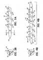
- Figure 1Aa side view of a barbed suture according to the present invention and generally designated at 1.
- Suture 1includes elongated body 2 that is generally circular in cross section and that terminates in end 4.
- End 4is illustrated in one embodiment as being pointed for penetrating tissue, but it is contemplated that end 4 may comprise a surgical needle (not shown) for insertion into tissue. (The other end is not shown.)
- suture 1includes plurality of closely spaced barbs 7, 9 arranged in a staggered uni-directional disposition. More specifically, axially spaced barbs 7 are radially arranged about 180 degrees from and staggered with respect to axially spaced barbs 9, with barbs 7, 9 facing pointed end 4.
- First set of barbs 7define a plane that is substantially coplanar with the plane defined by second set of barbs 9, and consequently, barbs 7, 9 define substantially the same one plane due to the radial 180 degree arrangement.
- Figure 1Bwhich is a cross sectional view along line 1B -1B of suture 1 in Figure 1A , more clearly illustrates angle X, namely the radial 180 degree arrangement of barbs 7 with respect to barbs 9.
- angle Xnamely the radial 180 degree arrangement of barbs 7 with respect to barbs 9.
- the stipplingillustrates that first barb 7 of barbs 7 is closer to pointed end 4 (not shown in Figure 1B ), and thus, seems to be larger than farther away first barb 9 of barbs 9, due to the staggering.
- a transverse plane that is perpendicular to suture body 2 and that intersects the base of one barb 7 of barbs 7does not intersect the base of any barb 9 of barbs 9.
- Suture 1may be made with a cutting machine that produces two sets of barbs 7, 9, usually one set at a time, in a staggered position along suture 1, such as the cutting device described in the above-noted Serial No. 09/943,733 to Genova et al.
- First set of barbs 7is created by placing and holding a suture filament in the vise, and then, the set of blades, with a predetermined length, splices into the suture filament at an angle selected to create barbs 7 pointing in one direction toward pointed end 4.
- Second set of barbs 9is created similarly after offsetting the blades longitudinally (to create the staggering) approximately half of the longitudinal distance between two of barbs 7 and also rotating the suture filament about 180 degrees on the vise, which is equipped to accommodate first set of barbs 7 that are already cut.
- suture 10Shown in Figure 2A is suture 10, which is another embodiment of the present invention and is like suture 1, except that suture 10 is bi-directional.
- Suture 10includes elongated body 12 that is generally circular in cross section. Elongated body 12 terminates in first and second pointed ends 14, 16 for penetrating tissue. Also, it is contemplated that one or both ends 14, 16 may comprise a surgical needle (not shown) for insertion into tissue. Also, suture 10 includes plurality of closely spaced barbs 17, 18, 19, 20 arranged in a staggered bi-directional disposition.
- plurality of axially spaced barbs 17are radially arranged about 180 degrees from and staggered with respect to plurality of axially spaced barbs 19, with barbs 17, 19 facing pointed end 14 for a portion (about half of the length) of suture 10.
- plurality of axially spaced barbs 18are radially arranged about 180 degrees from and staggered with respect to plurality of axially spaced barbs 20, with barbs 18, 20 facing pointed end 16 for another portion (approximately the other half of the length) of suture 10.
- First set of barbs 17, 18define a plane that is substantially coplanar with the plane defined by second set of barbs 19, 20.
- all of barbs 17, 18, 19, 20define substantially the same one plane due to the radial 180 degree arrangement of first set of barbs 17, 18 with respect to second set of barbs 19, 20.
- Figure 2Bis a cross sectional view along line 2B - 2B of suture 10 in Figure 2A , more clearly illustrating angle X, namely the radial 180 degree arrangement. Due to the staggering, first barb 17 of barbs 17 is closer to pointed end 14 (not shown in Figure 2B ), and thus, appears larger than farther away first barb 19 of barbs 19, as is illustrated by the stippling. A transverse plane that is perpendicular to suture body 12 and that intersects the base of one barb 17 of barbs 17 does not intersect the base of any barb 19 of barbs 19. Likewise, a transverse plane that is perpendicular to suture body 12 and that intersects the base of one barb 18 of barbs 18 does not intersect the base of any barb 20 of barbs 20.
- Suture 10may be made with the same cutting machine as suture 1, such as the cutting device described in the above-noted Serial No. 09/943,733 to Genova et al. , except with the following change in blade direction.
- first set of bi-directional barbs 17, 18after the suture filament is placed and held in the vise, the blades splice with a first cutting action into approximately half of the length of the suture filament to create barbs 17 facing in one direction toward pointed end 14.
- the bladesare rotated 180 degrees so that they are now disposed in the opposite direction and over the uncut half of the length.
- the bladesare then allowed to splice into the other half of the length of the suture filament with a second cutting action to create barbs 18 facing in the opposite direction toward pointed end 16.
- the bladesare offset longitudinally (to create the staggering) about half of the longitudinal distance between two of barbs 17, and also the suture filament is rotated about 180 degrees on the vice, which is equipped to accommodate first set of bi-directional barbs 17, 18 that are already cut.
- the bladessplice with a first cutting action into approximately half the length of the suture filament to create barbs 20 facing in one direction toward pointed end 16.
- the first cutting actionis followed by rotating the blades longitudinally 180 degrees so that they are now disposed in the opposite direction and over the uncut half of the length.
- the bladesare then allowed to splice into the other half of the length of the suture filament with a second cutting action to create barbs 19 facing in the opposite direction toward pointed end 14.
- the portion of suture 10 with barbs 17, 19may have them facing toward pointed end 16 and the portion of suture 10 with barbs 18, 20 may have them facing toward pointed end 14.
- the barbed suturewould be inserted into tissue with an insertion device, such as that shown in the above-noted U.S. Patent No. 5,342,376 to Ruff .
- barbsmay be escarped so that there may be two portions with barbs facing one end and one portion with barbs facing the other end, or two portions with barbs facing one end and two portions with barbs facing the other end, and so on (not shown), and thus, if a portion of barbs is not facing the suture end to which those barbs are adjacent, then, the barbed suture would be inserted into tissue with an insertion device.
- An advantage of a barbed suture having a radial 180 degree arrangement with staggeringis that the 180 degree spacing is readily fabricated on relatively small diameter filaments and the staggering improves anchoring performance. Thus, in thin and delicate tissue, where a smaller suture is desirable, the staggered 180 degree spacing generates effective anchoring performance.
- FIG 3Adepicted is a side view of another embodiment of a suture according to the present invention, and generally designated at suture 30.
- Suture 30is like suture 1 shown in Figure 1A , except that the radial spacing for suture 30 is 120 degrees instead of 180 degrees as is shown for suture 1.
- suture 30includes elongated body 32 that is generally circular in cross section and that terminates in pointed end 34 for penetrating tissue. It is contemplated that end 34 may comprise a surgical needle (not shown) so that the suture can be inserted into tissue. (The other end is not shown.) Additionally, suture 30 includes plurality of closely spaced barbs 35, 37, 39 arranged so that all face in the same direction toward pointed end 34. Hence, the disposition of barbs 35, 37, 39 is uni-directional.
- axial spaced barbs 35are radially arranged about 120 degrees from and staggered with respect to axially spaced barbs 37, which are radially arranged about 120 degrees from and staggered with respect to axially spaced barbs 39.
- axially spaced barbs 39are also arranged about 120 degrees from and staggered with respect to axially spaced barbs 35.
- first set of barbs 35define substantially the same one plane
- second set of barbs 37define substantially another same one plane
- third set of barbs 39define substantially still another same one plane.
- suture 30has barbs 35, 37, 39 arranged in a staggered uni-directional 120 degree disposition.
- Figure 3Bis a cross sectional view along line 3B - 3B of suture 30 in Figure 3A and shows with more particularity angle Y, namely the radial 120 degree arrangement of barbs 35 with respect to barbs 37, barbs 37 with respect to barbs 39, and barbs 39 with respect to barbs 35.
- first barb 35 of barbs 35because of the staggering, is closer to pointed end 34 (not shown in Figure 3B ), and thus, seems to be larger than farther away first barb 37 of barbs 37.
- first barb 37 of barbs 37due to the staggering, is closer to pointed end 34 (not shown in Figure 3B ), and thus, seems to be larger than even farther away first barb 39 of barbs 39.
- a transverse plane that is perpendicular to suture body 32 and that intersects the base of one barb 35 of barbs 35does not intersect the base of any barb 37 of barbs 37.
- a transverse plane that is perpendicular to suture body 32 and that intersects the base of one barb 37 of barbs 37does not intersect the base of any barb 39 of barbs 39.
- a transverse plane that is perpendicular to suture body 32 and that intersects the base of one barb 39 of barbs 39does not intersect the base of any barb 35 of barbs 35.
- Suture 30may be made with the same cutting machine as suture 1, such as the cutting device described in the above-noted Serial No. 09/943,733 to Genova et al.
- the cutting machineis now used to produce three sets of barbs 35, 37, 39, usually one set at a time, in a staggered position along suture 30.
- First set of barbs 35is created by placing and holding a suture filament in the vise, followed by the blades, after having been adjusted to a predetermined length, splicing into the suture filament at an angle that is chosen to create barbs 35 so that all are facing in the same direction toward pointed end 34.
- the bladesare offset longitudinally (to create the staggering) approximately half of the longitudinal distance between two of barbs 35.
- the filamentis rotated about 120 degrees on the vise, which is equipped to accommodate first set of barbs 35 that have already been cut, and then second set of barbs 37 is created in a similar manner.
- the bladesare again offset longitudinally (to create the staggering) approximately half the longitudinal distance between two of barbs 35, and also the suture filament is rotated about 120 degrees on the vise, which is equipped to accommodate both already cut first set of barbs 35 and already cut second set of barbs 37.
- third set of barbs 39is created in a similar manner.
- each successive barbis escarped at a position about 120 degrees around suture body 32 from the preceding barb and does not overlap with any other barb.
- Suture 40is similar to suture 30, except that suture 40 is bi-directional.
- Suture 40includes elongated body 42 that is generally circular in cross section and that terminates in first and second pointed ends 44, 46 for penetrating tissue. Also, it is contemplated that one or both ends 44, 46 may comprise a surgical needle (not shown) in order to be inserted into tissue.
- Suture 40further includes plurality of closely spaced barbs 47, 48, 49, 50, 51, 52 arranged in a staggered bi-directional disposition.
- axially spaced barbs 47are circumferentially arranged about 120 degrees from and staggered with respect to axially spaced barbs 49, which are radially arranged about 120 degrees from and staggered with respect to axially spaced barbs 51. Consequently, axially spaced barbs 51 are also arranged about 120 degrees from and staggered with respect to axially spaced barbs 47.
- a portion of suture 40has all of barbs 47, 49, 51 facing in the same direction toward pointed end 44.
- axially spaced barbs 48are radially arranged about 120 degrees from and staggered with respect to axially spaced barbs 50, which are radially arranged about 120 degrees from and staggered with respect to axially spaced barbs 52. Consequently, axially spaced barbs 52 are also arranged about 120 degrees from and staggered with respect to axially spaced barbs 48.
- another portion of suture 40has all of barbs 48, 50, 52 facing in the same direction toward pointed end 46.
- first set of barbs 47, 48define substantially the same one plane; second set of barbs 49, 50 define substantially another same one plane; and third set of barbs 51, 52 define substantially still another same one plane.
- Figure 4Bwhich is a cross sectional view along line 4B - 4B of suture 40 in Figure 4A , shows more clearly angle Y, namely the radial 120 arrangement with greater specificity.
- first barb 47 of barbs 47on account of the staggering, is closer to pointed end 44 (not shown in Figure 4B ), and thus, appears larger than farther away first barb 49 of barbs 49.
- first barb 49 of barbs 49is closer to pointed end 44 (not shown in Figure 4B ), and thus, appears larger than even farther away first barb 51 of barbs 51.
- a transverse plane that is perpendicular to suture body 42 and that intersects the base of one barb 47 of barbs 47does not intersect the base of any barb 49 of barbs 49.
- a transverse plane that is perpendicular to suture body 32 and that intersects the base of one barb 49 of barbs 49does not intersect the base of any barb 51 of barbs 51.
- a transverse plane that is perpendicular to suture body 42 and that intersects the base of one barb 51 of barbs 51does not intersect the base of any barb 47 of barbs 47.
- a transverse plane that is perpendicular to suture body 42 and that intersects the base of one barb 48 of barbs 48does not intersect the base of any barb 50 of barbs 50.
- a transverse plane that is perpendicular to suture body 32 and that intersects the base of one barb 50 of barbs 50does not intersect the base of any barb 52 of barbs 52.
- a transverse plane that is perpendicular to suture body 42 and that intersects the base of one barb 52 of barbs 52does not intersect the base of any barb 48 of barbs 48.
- Suture 40may be made with the same cutting machine as suture 1, such as the cutting device described in the above-noted Serial No. 09/943,733 to Genova et al. , except with the following change in blade direction.
- first set of bi-directional barbs 47, 48after the suture filament is placed and held in the vise, the blades splice with a first cutting action into approximately half of the length of the suture filament to create barbs 47 facing in one direction toward pointed end 44. Then, the blades are rotated 180 degrees so that they are now disposed in the opposite direction and over the uncut half of the length. The blades then are allowed to splice into the other half of the length of the suture filament with a second cutting action to create barbs 48 facing in the opposite direction toward pointed end 46.
- the bladesare offset longitudinally (to create the staggering) for about half the longitudinal distance between two of barbs 47, and also the suture filament is rotated about 120 degrees on the vise, which is equipped to accommodate first set of bi-directional barbs 47, 48 that are already cut.
- the bladessplice with a first cutting action into approximately half of the length of the suture filament to create barbs 50 facing in one direction toward pointed end 46.
- the first cutting actionis followed by rotating the blades 180 degrees so that they are now disposed in the opposite direction and over the uncut half of the suture filament. They then splice into the other half of the length of the suture filament with a second cutting action to create barbs 49 facing in the opposite direction toward pointed end 44.
- the bladesare again offset longitudinally (to create the staggering) for about half the longitudinal distance between two of barbs 47.
- the suture filamentagain is rotated about 120 degrees on the vise, which is equipped to accommodate already cut first set of bi-directional barbs 47, 48 and already cut second set of bi-directional barbs 49, 50.
- the third set of bi-directional barbs 51, 52are made by having the blades splice with a first cutting action into approximately half of the length of the suture filament to create barbs 51 facing in one direction toward pointed end 44.
- the first cutting actionis followed by rotating the blades 180 degrees so that they are now disposed in the opposite direction and over the uncut half of the suture filament. They next splice into the other half of the length of the suture filament with a second cutting action to create barbs 52 facing in the opposite direction toward pointed end 46.
- each successive barbis escarped at a position about 120 degrees around suture body 42 from the preceding barb and does not overlap with any other barb.
- the portion of suture 40 having barbs 47, 49, 51may have them facing toward pointed end 46 and the portion of suture 40 having barbs 48, 50, 52 may have them facing toward pointed end 44.
- the barbed suturewould be inserted into tissue with an insertion device, such as that shown in the above-noted U.S. Patent No. 5,342,376 to Ruff .
- barbsmay be escarped so that there may be two portions with barbs facing one end and one portion with barbs facing the other end, or two portions with barbs facing one end and two portions with barbs facing the other end, and so on (not shown), and thus, if a portion of barbs is not facing the suture end that those barbs are adjacent, then, the barbed suture would be inserted into tissue with an insertion device.
- An advantage of a barbed suture with a radial 120 degree arrangementis that the barbs exert force in three distinct planes that compliment each other, resulting in maximization of the retention force of the suture overall. As noted above, the staggering enhances anchoring performance.
- Suture 60includes elongated body 62 of generally circular cross section. Elongated body 62 terminates in pointed end 64 for penetrating tissue. Also, it is contemplated that end 64 may comprise a surgical needle (not shown) for insertion into tissue. Furthermore, suture 60 includes plurality of closely spaced barbs 67 arranged in a twist cut multiple spiral pattern around body 62 and facing in the same direction toward pointed end 64.
- Figure 5Bis a cross sectional view along line 5B - 5B of suture 60 in Figure 5A . Due to the twist cut multiple spiral disposition, each respective barb 67 seems to be smaller and smaller as each is farther and farther away from pointed end 64 (not shown in Figure 5B ), the illusion of size difference being illustrated by the stippling.
- Suture 60may be constructed with a similar cutting machine as that used for making suture 1, such as the cutting device described in the above-noted Serial No. 09/943,733 to Genova et al. With a twist cutting method, barbs 67 may be produced in multiple spirals that preferably are created at the same time as the suture filament is held stationary, instead of being rotated, when the cutting takes place.
- a suture filamentthat is about 7 inches (about 178 mm) in length, is longitudinally twisted for a portion of the suture length, such as 39 times for a portion that is about 4.5 inches (about 114 mm) of the suture length.
- an endis secured, and the other end is grasped and rotated 360 degrees, 39 times, so the portion of the suture filament is twisted when the suture is then placed and held in the vise.
- Twistingpreferably is performed 28 to 50 times, and may be performed more or less, such as 19 to 70 times.
- twistingmay be from about 2 to about 17 twists per inch, or about 3 to about 15 twists per inch, or about 5 to about 13 twists per inch (per inch being per 25.4 mm).
- the bladesafter having been adjusted to a predetermined length, simultaneously splice into the suture filament.
- the cutting actionmakes cuts to create barbs 67 so that all are facing in the same direction toward pointed end 64.
- barbs 67are disposed in multiple spirals on suture 60.
- Suture 70is of a twist cut multiple spiral disposition and thus is similar to suture 60, except that suture 70 is bi-directional.
- Suture 70includes elongated body 72 that is generally circular in cross section and that terminates in first and second pointed ends 74, 76 for penetrating tissue. It is contemplated that one or both of ends 74, 76 may comprise a surgical needle (not shown) for insertion into tissue.
- Suture 70further includes plurality of closely spaced barbs 77, 78 arranged in two respective spiral patterns, each being a multiple spiral around body 72.
- Barbs 77, 78are disposed on middle portion MP that is approximately 3 inches (approximately 76 mm) of suture 70, with each end portion EP of suture 70 being barb-free.
- plurality of barbs 77are arranged in a multiple spiral pattern with all barbs 77 facing toward pointed end 74 for a part (about half) of middle portion MP along the length of suture 70.
- plurality of barbs 78are arranged in a multiple spiral pattern with all barbs 78 facing toward pointed end 76 for another part (the other approximate half) of middle potion MP along the length of suture 70.
- Figure 6Bis a cross sectional view along line 6B - 6B of suture 60 in Figure 6A . Due to the multiple spiral configuration, each respective barb 77 seems to be smaller and smaller as each is farther and farther away from pointed end 74 (not shown in Figure 6B ), as illustrated by the stippling.
- Suture 70may be made with the same cutting machine as suture 60, such as the cutting device described in the above-noted Serial No. 09/943,733 to Genova et al. , but with the following change in blade direction.
- barbs 77may be produced in multiple spirals that preferably are created at the same time, and then after the direction change for the blades, barbs 78 may be produced in multiple spirals that preferably are created at the same time.
- the suture filamentis held stationary instead of being rotated.
- a section of about 4.5 inches (about 114 mm) in length of a suture filamentis twisted, such as 39 times for a suture about 7 inches (about 178 mm) in length.
- an endis secured, and the other end is grasped and rotated 360 degrees, 39 times, so the twisted section of the suture filament has about 8 2/3 twists per inch (per 25.4 mm) when the suture filament is then is placed and held in the vise.
- Twistingpreferably is performed 28 to 50 times, and may be performed more or less, such as 19 to 70 times.
- twistingmay be from about 2 to about 17 twists per inch, or about 3 to about 15 twists per inch, or about 5 to about 13 twists per inch (per inch being per 25.4 mm).
- the bladesafter having been adjusted to a predetermined length, splice into approximately half of the approximately 3 inch (approximately 76 mm) length of middle portion MP of the approximately 4.5 inch (approximately 114 mm) twisted section of the suture filament in a first cutting action with the blades making cuts to create barbs 77 so that all are facing in one direction toward pointed end 74.
- the bladesare rotated 180 degrees so that they are now disposed in the opposite direction and over the other half of the approximately 3 inch (approximately 76 mm) length - of middle portion MP of the approximately 4.5 inch (approximately 114 mm) twisted section of the suture filament.
- the bladesare then allowed to splice into the other half in a second cutting action with the blades making cuts to create barbs 78 so that all are facing in the opposite direction toward pointed end 76.
- the first cuts and the second cutsresult in barbs 77, 78 being in two respective multiple spiral patterns on two respective portions of suture 70, the two respective portions defining middle portion MP of about 3 inches (about 76 mm) in length.
- Each suturecontained a total of 78 barbs introduced in two respective multiple spiral patterns around the circumference of the suture. Since the barbed suture was bi-directional, the barbs were divided into a left group with 39 barbs disposed on a first portion of the suture and a right group with 39 barbs on a second portion of the suture, each group opposing the direction of the other group from the approximate middle of the suture.
- Each suturewas about 7 inches (about 178 mm) long.
- the middle portion MPwas about 3 inches (about 76 mm) long and contained the 78 barbs that were escarped into the suture filament. Extending beyond the 3 inch (76 mm) barbed middle portion MP were two unbarbed end portions EP of the suture that were each about 2 inches (about 51 mm) long.
- one or both ends of the barbed suturemay be sufficiently pointed and rigid for insertion into tissue, or may comprise a straight or curved surgical needle.
- the strength of the twist cut, 7 inch (178 mm) barbed sutureswas tested by two methods. One method was a straight pull tensile strength test with a Universal Tester and the other method was an in vivo performance test with dogs. ,
- testingwas performed using a Test Resources Universal Tester, Model 200Q. The average reading of 10 repeated measurements made for each kind of suture was recorded for the barbed sutures and for the comparison unbarbed sutures.
- Comparison unbarbed sutureswere polydioxanone monofilaments (a synthetic absorbable suture material) of various suture diameters of about 0.018 inch (about 0.457 mm), about 0.015 inch (about 0.381 mm), and about 0.0115 inch (about 0.292 mm), which are respectively slightly larger than the United States Pharmacopoeia sizes 0, 2-0, and 3-0 for synthetic absorbable sutures.
- size 0has a diameter range of about 0.35 mm to about 0.399 mm
- size 2-0has a diameter range of about 0.30 mm to about 0.339 mm
- size 3-0has a diameter range of about 0.20 mm to about 0.249 mm.
- Each barbed suturewas gripped at each end by being held with cork gasket padding in two respective serrated jaws, whereas each unbarbed suture was gripped at each end by being wrapped around two respective capstan roller grips. Capstan rollers were used for holding the unbarbed sutures to avoid stress and distension.
- each suture specimen between the two gripped placeswas about 5 inches (about 126 mm) in length, which, in the case of barbed sutures, contained the entire 3 inches (76 mm) of the barbed middle portion.
- the straight pull tensile strength of 7.03 pounds at breakage for the size 0 polydioxanone barbed suture(which, due to the escarpment of the barbs, has an effective diameter that is smaller than the diameter of the conventional unbarbed size 0 polydioxanone suture) compared favorably with the minimum USP knot pull requirement of 8.60 pounds for the size 0 polydioxanone conventional unbarbed suture.
- each incisionwas made at the thorax (twice), thigh (twice), flank, ventral midline, and paramedian, each of the 7 incisions having 1, 2, or 3 closure sites.
- the length of each incisionranged from about 0.5 inch (about 12.5 mm) to about 4 inches (about 101 mm) and the depth of each incision was from the superficial dermis to the peritoneum.
- the dogswere monitored daily, and then subjected to euthanasia at 14 days. At the time of death, the incisions were evaluated macroscopically. With regard to various tissues, incision sizes, and locations on the dogs, all sites apposed with the size 0 polydioxanone barbed sutures stayed closed and appeared to be healing normally throughout the 14 day observation period. No dehiscence occurred.
- the in vivo performance of the size 0 polydioxanone barbed sutureswas efficacious when compared to the size 2-0 silk braided filament unbarbed sutures, the size 2-0 nylon monofilament unbarbed sutures, and the size 3-0 polydioxanone monofilament unbarbed sutures.
- multiple spiral suture 70the portion of suture 70 on which is disposed barbs 77 may have barbs 77 facing toward pointed end 76 and the portion of suture 70 on which is disposed barbs 78 may have barbs 78 facing toward pointed end 74.
- the barbed suturewould be inserted into tissue with an insertion device, such as that shown in the above-noted U.S. Patent No. 5,342,376 to Ruff .
- barbsmay be escarped so that there may be 2 portions with barbs facing an end and 1 portion with barbs facing the other end, or 2 portions with barbs facing an end and 2 portions with barbs facing the other end, and so on (not shown), and thus, if a portion of barbs is not facing the suture end to which those barbs are adjacent, then, the barbed suture would be inserted into tissue with an insertion device.
- a barbed suture having a twist cut, multiple spiral dispositionaffords better wound holding capability as compared to the 120 degree spaced barbed suture.
- the reasonis that the twist cut, multiple spiral pattern results in groups of barbs that complement successive and preceding groups of barbs, which tends to provide improved anchoring when the suture is in tissue.
- This featureis especially useful for tissue such as fat tissue, which has fewer connective fibers compared with other types of tissues, so that greater suture retention force is desirable.
- Barbed suture 80has plurality of closely spaced barbs 81 on elongated suture body 82 of generally circular cross section. Each barb 81 has barb tip 85. Shown are suture longitudinal axis A, suture diameter SD, barb length L, barb cut depth D, barb cut angle ⁇ , cut distance P, spirality angle ⁇ , cut-out depression CD, and tip T of cut-out depression CD.
- Figure 7Bis the sectional side view as illustrated in Figure 7A , but rotated and clamped to align the barbs for measurement of the cut distance P between barbs 81.
- Barbed suture 80is a twist cut, multiple spiral, bi-directional barbed suture, like suture 70 in Figure 6A , but illustrated as an enlarged section in order to show more detail with respect to the configuration of barbs 81 vis-a-vis suture longitudinal axis A, suture diameter SD, barb length L, barb cut depth D, barb cut angle ⁇ , cut distance P, spirality angle ⁇ , cut-out depression CD, and terminus T of cut-out depression CD.
- the middle portionwas about 3 inches (about 76 mm) of the suture and contained the 78 barbs that were escarped into the suture filament. Extending beyond the 3 inch (76 mm) barbed middle portion toward each suture end were two unbarbed end portions of the suture filament that were each about 2 inches (about 51 mm) long.
- one or both ends of the barbed suturemay be sufficiently pointed and rigid for insertion into tissue, or may comprise a straight or curved needle.
- angle ⁇ of spiralitywas measured microscopically on various barbed sutures 80 as follows.
- line Mwill be parallel to the longitudinal axis of the vise while the twisted suture filament is being held in the vise. If the vise does not leave a light mark on the suture filament, then line M can be determined in that it is parallel to a line connecting the two respective terminus T of the two successive cut-out depressions CD left in suture body 82 from the escarpment of two successive barbs 81.
- line Mspirals on suture body 82 around barbed suture 80, forming angle ⁇ of spirality.
- the Optem Zoom 100 custom microscopewas set with ring lighting at 60 and back lighting at coarse 12 and fine 10. Also, imaging analysis system software was used. Spirality angle ⁇ was then measured between the outer surface of the barbed suture and line M. The average was calculated for 10 repeated measurements (5 from the left group of barbs and 5 from the right group of barbs on the same suture).
- barbed suture 80was mounted in a twisting device with one end of suture 80 clamped in a fixed position. The other end of suture 80 was rotated to insert twist until barbs 81 were aligned.
- longitudinal cut distance P between two adjacent barbs 81was measured microscopically between the two respective terminus T of the two successive cut-out depressions CD left in suture body 82 from the escarpment of two successive barbs 81. The average was calculated for 10 repeated measurements (5 from the left group of barbs and 5 from the right group of barbs on the same suture).
- Table 7ASize 0 barbed suture
- Table 7BSize 0 barbed suture
- Table 7CSize 0 barbed suture
- angle ⁇was performed on a few additional bi-directional twist cut, multiple spiral barbed sutures with a diameter of about 0.018 inch (about 0.457 mm, slightly more than the USP requirement for a size 0 synthetic absorbable suture).
- the mean averagewas 16.87 and the standard deviation was ⁇ 0.85.
- Table 7E(size 3-0 barbed suture) Measurement Units Average Standard Deviation Ratio of D, L, or P over Suture Diameter (0.292 mm) cut angle ⁇ degrees 166 1.651 not applicable cut depth D mm 0.107 0.007 0.37 cut length L mm 0.443 0.042 1.52 cut distance P mm 0.956 0.079 3.27 spirality angle ⁇ degrees not tested not applicable not applicable Table 7F (size 3-0 barbed suture) Measurement Units Average Standard Deviation Ratio of D, L, or P over Suture Diameter (0.292 mm) cut angle ⁇ degrees 164 2.055 not applicable cut depth D mm 0.106 0.006 0.36 cut length L mm 0.395 0.042 1.35 cut distance P mm 0.959 0.074 3.28 spirality angle ⁇ degrees 7.329 0.547 not applicable Table 7G (size 3-0 barbed suture) Measurement Units Average Standard Deviation Ratio of D, L, or P over Suture Diameter (0.292 mm) cut angle ⁇ degrees
- Table 7K(size 0 barbed suture) Measurement Units Average Standard Deviation Ratio of D, L, P over Suture Diameter (0.457 mm) cut angle ⁇ degrees 152.6 0.718 not applicable cut depth D mm 0.221 0.011 0.48 cut length L mm 0.479 0.022 1.05 cut distance P mm 0.784 0.015 1.71 spirality angle ⁇ degrees 12.9 0.453 not applicable Table 7L (size 0 barbed suture) Measurement Units Average Standard Deviation Ratio of D, L, P over Suture Diameter (0.457 mm) cut angle ⁇ degrees 152.4 0.947 not applicable cut depth D mm 0.216 0.014 0.47 cut length L mm 0.465 0.024 1.02 cut distance P mm 0.774 0.015 1.69 spirality angle ⁇ degrees
- a suitable ratio of cut length L to barbed suture diameter SDranges from about 0.2 to about 2, more preferably from about 0.4 to about 1.7, even more preferably from about 0.8 to about 1.5.
- very suitable barbed suturesmay have a ratio of cut length L to barbed suture diameter SD from about 1 down to about 0.2, whereby the ratio of the highest possible barb elevation (the elevation of barb tip 85 above suture body 82) to the suture diameter SD correspondingly ranges from about 1 down to about 0.2.
- a suitable ratio of cut depth D to barbed suture diameter SDranges from about 0.05 to about 0.6, more preferably from about 0.1 to about 0.55, even more preferably from about 0.2 to about 0.5.
- length Lmay be desirably varied depending on the intended end use, since larger barbs are more suitable for joining certain types of tissue such as fat tissue or soft tissue, whereas smaller barbs are more suitable for joining other types of tissues such as fibrous tissue.
- a barb configurationthat is a combination of large, medium, and/or small barbs disposed on the same suture will be desirable, for instance, when the barbed suture is employed in tissue that has differing layer structures.
- Cut angle ⁇ formed between the barb and the elongated suture bodydesirably would range from about 140 degrees to about 175 degrees, more preferably would range from about 145 degrees to about 173 degrees.
- the most preferred cut angle ⁇ for all barbsranges from about 150° to about 170°.
- the preferred barb length Lwould be 0.45 mm; the preferred barb depth D would be 0.2 mm; and the preferred barb cut angle would be 153 degrees.
- a suitable ratio of cut distance P to barbed suture diameter SDranges from about 0.1 to about 6, more preferably from about 0.5 to about 4.5, even more preferably from about 1.0 to about 3.5.
- Very suitable barbed suturesmay have a ratio of cut distance P to barbed suture diameter SD from about 1.5 down to about 0.2, whereby cut distance P may be as low as about 0.1, particularly for the overlapping barb embodiment, which is discussed in more detail below vis-à-vis Figures 12A, 12B, 12C, and 12D .
- spirality angle ⁇ formed between line M and the longitudinal direction of the elongated suture body for a twist cut, multiple spiral barbed suturetypically would range from about 5 degrees to about 25 degrees, more preferably from about 7 degrees to about 21 degrees.
- the most preferred angle ⁇ for all barbs on a twist cut, multiple spiral barbed sutureis about 10° to about 18°.
- Suture 90which is another embodiment of the present invention.
- Suture 90includes elongated body 92 that is generally circular in cross section.
- Elongated body 92terminates in first and second pointed ends 94, 96 for penetrating tissue. It is contemplated that one or both ends 94, 96 may comprise a surgical needle (not shown) for insertion into tissue.
- suture 90includes plurality of closely spaced barbs 97 arranged in a random disposition.
- Suture 90may be made with the same cutting machine as the above-discussed sutures, such as the cutting device described in the above-noted Serial No. 09/943,733 to Genova et al.
- the 180 degree disposition(sutures 1, 10), the 120 degree disposition (sutures 30, 40), and/or the twist cut multiple spiral disposition (sutures 60, 70, 80)
- barbed suture 90 with a very random barb dispositionis obtained.
- the advantage of the random dispositionis that the many barb angles provide superior anchoring in tissues and thus afford superior wound holding properties.
- the barbed suturewould be inserted into tissue with an insertion device, such as that shown in the above-noted U.S. Patent No. 5,342,376 to Ruff .
- Suture 100includes elongated suture body 102 of generally circular cross section. Also, suture body 102 has disposed on it a plurality of closely spaced barbs 107. Each barb 107 has a barb configuration such that barb underside 108 is serrated or corrugated.
- One or both suture endsare pointed for penetrating tissue and it is contemplated that one or both may comprise a surgical needle (not shown) for insertion into tissue.
- Suture 100may be made with the same cutting machine as the above-discussed sutures, such as the cutting device described in the above-noted Serial No. 09/943,733 to Genova et al.
- Barb 107 having serrated underside 108is achieved by vibrating or oscillating the cutting blades of the cutting device when barbs are being escarped into the body of a monofilament. It is intended that any of the barbed sutures of the present invention as described here may have barbs with a configuration that includes a serrated or corrugated underside.
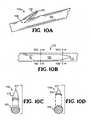
- FIG. 10 Adepicted in Figure 10 A is a perspective view and depicted in Figure 10B is a top view of barbed suture 110, which is another embodiment of the present invention.
- Suture 110includes elongated suture body 112 of generally circular cross section. Also, suture body 112 has disposed on it a plurality of closely spaced barbs 115 having barb tips 117 (one barb 115 is shown for purposes of brevity). Barb 115 has a configuration with an arcuate base 119 where barb 115 is attached to suture body 112.
- One or both suture endsare pointed for penetrating tissue and it is contemplated that one or both may comprise a surgical needle (not shown) for insertion into tissue.
- Figures 10C and 10Dare cross-sectional views respectively along line 10C-10C and line 10D-10D of Figure 10B. Figure 10C and 10D further clarify that barb 115 becomes narrower going from base 119 toward tip 117.
- Suture 110may be made with the same cutting machine as the above-discussed sutures, such as the cutting device described in the above-noted Serial No. 09/943,733 to Genova et al.
- the cutting deviceis provided with cutting blades with ends that are correspondingly arcuate with respect to arcuate base 119.
- any of the barbed sutures of the present invention as described heremay have barbs with a configuration that includes an arcuate base.
- the arcuate baseshould enhance tissue anchoring as compared to a flat, linear base. Regardless, it is not desired for the base to be circular or oval, which would result from conical shaped barbs, as that could decrease tissue anchoring.
- Shown in Figure 11is a sectional side view of a barbed suture that is another embodiment of the present invention, and that is generally designated at 120.
- Suture 120includes elongated body 122 that is generally circular in cross section. Elongated body 122 terminates in end 124. End 124 is pointed for penetrating tissue and it is contemplated that end 124 may comprise a surgical needle (not shown) for insertion into tissue. (The other end is not shown, and also may be pointed for penetrating tissue and may comprise a surgical needle for penetrating tissue.)
- suture 120includes plurality of closely spaced barbs 125, plurality of closely spaced barbs 127, and plurality of closely spaced barbs 129.
- Barbs 125are relatively small in size with a relatively short barb length as compared to barbs 127, which are relatively medium in size with a relatively medium barb length, as compared to barbs 129, which are relatively large in size with a relatively long barb length.
- Suture 120may be made with the same cutting machine as the above-described sutures were made, such as the cutting device described in the above-noted Serial No. 09/943,733 to Genova et al.
- the barb cut lengthis made longer or shorter, as desired, to result in each of the three sets of barbs 125, 127, and 129 being of a size different from the others, where the varying sizes are designed for various surgical applications.
- the barb sizemay also vary in the transverse direction, whereby the barb base may be short, medium, or long, and regardless, the barb base typically is less than about 1/4 of the suture diameter.
- relatively larger barbsare desirable for joining fat and soft tissues, whereas relatively smaller barbs are desirable for joining fibrous tissues.
- Use of a combination of large, medium, and/or small barbs on the same suturehelps to ensure maximum anchoring properties when barb sizes are customized for each tissue layer. Only two different sized sets of barbs (not shown) may be escarped into suture body 122, or additional sets of barbs (not shown) with four, five, six, or more different sized sets than three sizes as illustrated for sets of barbs 125, 127, and 129 may be escarped into suture body 122 as desired, in accordance with the intended end use.
- suture 120is illustrated with the barbs being unidirectional, it is intended that barbed sutures with barbs having a configuration of varying sizes in accordance with the invention also may be bi-directional barbed sutures or random barbed sutures or any of the other inventive barbed sutures described here.
- Figure 12Ais a perspective view of another embodiment of the present invention, showing barbed suture 130 having elongated body 132 of generally circular cross section.
- One or both suture endsare pointed for penetrating tissue and it is contemplated that one or both ends may comprise a surgical needle (not shown) for insertion into tissue.
- Suture 130further includes plurality of barbs 135 projecting from body 132 such that at least two longitudinally adjacent first and second barbs 135 are disposed on body 132 where first barb 135 overlaps second barb 135 if first and second barbs 135, which is readily apparent if barbs 135 are laid flat on body 132.
- Figure 12Bis a perspective view of a portion of overlapping barbs 135 of the overlapping disposition barbed suture 130 of Figure 12A
- Figure 12Cis a top plan view of Figure 12B
- Figure 12Dis a cross-sectional view along ling 12D - 12D of Figure 12C .
- overlapping first barb 135is escarped into part of topside TS of overlapped second barb 135, and so on.
- Part of topside TS of overlapped second barb 135becomes part of underside US of overlapping first barb 135.
- the barb cut distance between first barb 135 and second barb 135may be shorter than the barb cut length of overlapped second barb 135, whereas, in general for barbed sutures, the barb cut distance between two barbs ⁇ the barb cut length.
- very suitable barbed suturesmay have a ratio of the barb cut distance to the barbed suture diameter from about 1.5 down to about 0.2, since the barb cut distance P may be as low as about 0.1. (See discussion of Figure 7 for comments vis-à-vis the barb cut length and the barb cut distance.)
- This overlapping dispositionallows for closely packing many barbs 135 on body 132, and typically, barbs 135 are thin, as compared to when the barb cut distance between two barbs ⁇ the barb cut length.
- suture 130is illustrated with barbs 135 being unidirectional, it is intended to include that suture 130 in accordance with the invention also may be a bi-directional barbed suture as described here.
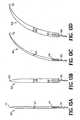
- Figures 13A, 13B, 13C, and 13Dshow various surgical needles, where a barbed suture is attached to each surgical needle.
- the surgical needlesmay be coated with a polymer, for instance, as described above vis-à-vis U.S. Patent No. 5,258,013 to Granger et al.
- Figure 13Ashows surgical needle N1 that is a straight elongated needle in the longitudinal direction and that is generally circular in cross section.
- Surgical needle N1has pointed tip T1 for insertion into tissue and also has hole H1.
- Surgical needle N1is illustrated as attached, such as by swaging, to barbed suture S1.
- Barbed suture S 1is a barbed suture including, but not limited to, any of the above-described barbed sutures.
- surgical needle N1has diameter D1 in the transverse direction, which is illustrated as a relatively thin diameter, such as about 0.02 inch (about 0.51 mm).
- surgical needle N1after having suture S1 inserted into hole H1, may be crimped by standard procedures about hole H1 to hold suture S1 in place for suturing tissue.
- Figure 13Bshows surgical needle N2 that is a straight elongated needle in the longitudinal direction and that is generally circular in cross section.
- Surgical needle N2has pointed tip T2 for insertion into tissue and also has hole H2.
- Surgical needle N2is illustrated as attached, such as by swaging, to barbed suture S2.
- Barbed suture S2is a barbed suture including, but not limited to, any of the above-described barbed sutures.
- surgical needle N2has diameter D2 in the transverse direction, which is illustrated as a suitably thin diameter, such as about 0.032 inch (about 0.81 mm), but not as thin as diameter D1 of surgical needle N1.
- surgical needle N2after having suture S2 inserted into hole H2, may be crimped by standard procedures about hole H2 to hold suture S2 in place for use in suturing tissue.
- Figure 13Cshows surgical needle N3 that is a curved elongated needle in the longitudinal direction and that is generally circular in cross section.
- Surgical needle N3has pointed tip T3 for insertion into tissue and also has hole H3.
- Surgical needle N3is illustrated as attached, such as by swaging, to barbed suture S3.
- Barbed suture S3is a barbed suture including, but not limited to, any of the above-described barbed sutures.
- surgical needle N3has diameter D3 in the transverse direction, which is illustrated as a relatively thin diameter, such as about 0.02 inch (about 0.51 mm).
- surgical needle N3, after having suture S3 inserted into hole H3,may be crimped by standard procedures about hole H3 to hold suture S3 in place for use in suturing tissue.
- Figure 13Dshows surgical needle N4 that is a curved elongated needle in the longitudinal direction and that is generally circular in cross section.
- Surgical needle N4has pointed tip T4 for insertion into tissue and also has hole H4.
- Surgical needle N4is illustrated as attached, such as by swaging, to barbed suture S4.
- Barbed suture S4is a barbed suture including, but not limited to, any of the above-described barbed sutures.
- surgical needle N4has diameter D4 in the transverse direction, which is illustrated as a suitably thin diameter, such as about 0.032 inch (about 0.81 mm), but not as thin as diameter D3 of surgical needle N3.
- surgical needle N4after having suture S4 inserted into hole H4, may be crimped by standard procedures about hole H4 to hold suture S4 in place for use in suturing tissue.
- Needle tips T1, T2, T3, and T4are schematically illustrated as pointed, but, as is well known, surgical needles come with various kinds of pointed tips, such as taper point, taper cutting, ball point, cutting edge, diamond point, thin line, and lancet point, and it is intended to include, but not be limited to, all such needle tips. Taper point, taper cutting, and diamond point are preferred needle tips for surgical needles used with barbed sutures.
- needle diameter for surgical needles used with conventional (i.e., unbarbed) suturesis considered unimportant, and often very thick surgical needles are used with thin conventional sutures such that the ratio of surgical needle diameter to conventional suture diameter is 4:1 or even higher, such as 4.43:1.
- the thinner that the surgical needle isthen the more preferable that the surgical needle/barbed suture is, with the desired needle diameter being thinner and thinner as it approaches the barbed suture diameter, and it is possible, although not as claimed in the present invention, that the needle diameter may be even thinner than the barbed suture diameter.
- a relatively thin surgical needle attached to a barbed sutureis more preferable for approximating tissue when stitching a wound closed than a relatively thick surgical needle threaded with a barbed suture.
- the reasonis that the relatively thin surgical needle attached to a barbed suture allows for greater engagement of barbs in tissue, and therefore provides better closure strength to the approximated tissue that has been sutured to prevent the opposing sides of the closed wound from pulling apart, as compared to the closure strength provided to approximated tissue that has been sutured with the relatively thick surgical needle.
- the surgical needle diametershould be of sufficient width in order to make a hole or a channel in the end, such by drilling, to allow for insertion of the barbed suture into the hole or the channel. Nevertheless, as the surgical needle diameter increases, the surgical needle is still suitable as long as the ratio of the surgical needle diameter to the barbed suture diameter is about 3:1 or less.
- a desirable ratio of surgical needle diameter to barbed suture diameteris about 3:1 or less, more preferably about 2:1 or less, most preferably about 1.8:1 or less.
- the ratio of surgical needle diameter to barbed suture diametermay be, although not as claimed in the present invention, as low as about 1:1 or less, or even lower, for instance, about 0.9:1 or less, or about 08:1 or less, or as low as about 0.5:1. It will be appreciated by the person of ordinary skill in the art that care should be taken with extremely thin needles so as to ameliorate the possibility of localized weakness, which may compromise tissue insertion.
- Closure strength of thin surgical needlesboth having a ratio of surgical needle diameter to barbed suture diameter suitable for the present invention, was tested as follows.
- a first specimenwas made from a piece of chamois leather by stitching together the respective edges of the wound with a drilled end surgical needle (item no. 382077A purchased from Sulzle Company) which was swaged with a barbed suture.
- a drilled end surgical needle(item no. 382077A purchased from Sulzle Company) which was swaged with a barbed suture.
- the needlewas crimped about the hole to secure the barbed suture during stitching.
- the piece of chamois leatherwas cut to a rectangular shape of about 3 inches (about 76 mm) in length by about 1.25 inches (about 32 mm) in width, where the stitched wound was in the middle of the length and transverse the width.
- the needlewas a taper point, curved surgical needle (3/8 of a circle), with a length of about 22 mm and a relatively thin diameter of about 0.020 inch (about 0.51 mm).
- a second specimenwas made from another piece of chamois leather by stitching together the respective edges of the wound, using a drilled end surgical needle (item no. 383271A purchased from Sulzle Company) swaged with the same kind of barbed suture, i.e., the surgical needle was crimped about the needle hole, after insertion of the barbed suture into the hole, to secure the barbed suture during stitching.
- the needlewas a taper point curved surgical needle (3/8 of a circle) with a length of about 22 mm and a suitable thin diameter of about 0.032 inch (about 0.81 mm), although not as thin as the diameter of the needle used for first specimen.
- Each barbed suture for each specimenwas a bi-directional, twist cut multiple spiral, polydioxanone barbed suture like suture 70 in Figure 6A , except that each barbed suture had a diameter of about 0.0115 inch (about 0.291 mm, which is slightly larger than the USP requirement for a size 3-0 synthetic absorbable suture), instead of a suture diameter of about 0.018 inch (about 0.457 mm).
- Both the first and the second specimens of stitched chamois clothwere tested for closure strength using a Test Resources Universal Tester, Model 200Q. Each specimen was gripped by two respective serrated jaws. Then, each specimen was pulled longitudinally at a rate of about 10 inches per minute (about 254 mm per minute) until complete rupture. The peak load in pounds reached before complete wound disruption was recorded as the closure strength.
- Table 13A(Chamois Cloth Closure Strength) Specimen Needle Diameter Barbed Suture Diameter Ratio* Pounds to Rupture First 0.020 inch 0.0115 inch 1.74 5.88 Second 0.032 inch 0.0115 inch 2.78 2.88 *Ratio of surgical needle diameter to barbed suture diameter.
- one of the two woundswas closed with a drilled end, curved surgical needle that was a Sulzle item no. 382273A, which was 3/8 circle.
- the needlehad a length of 18mm and a diameter of about 0.022 inch (about 0.56 mm). Also, the needle had a taper point needle tip where the needle tip had been ground to a 3-facet cut to approximate a taper cutting needle tip to facilitate penetration of rat tissue.
- the needlewas swaged to a barbed suture.
- the other of the two woundswas closed using the same suturing technique, but with a drilled end, curved surgical needle that was a Sulzle item no. 832679A, which was 3/8 circle.
- the needlehad a length of about 18 mm and a diameter of about 0.026 inch (about 0.66 mm). Also, the needle had a diamond point needle tip. The needle was swaged to a barbed suture.
- Each barbed suture for each specimenwas a bi-directional, twist cut multiple spiral, polydioxanone barbed suture like suture 70 in Figure 6A , except that each barbed suture had a diameter of about 0.015 inch (about 0.381 mm, which is slightly larger than the USP requirement for a size 2-0 synthetic absorbable suture), instead of a suture diameter of about 0.018 inch (about 0.457 mm).
- tissue specimenthat was approximately a square measuring about 4 cm x about 4 cm, with the stitched wound in the middle paralleling two opposing tissue edges, was retrieved for closure strength testing.
- the force to open each woundwas determined using a Test Resources Universal Tester, Model 200Q.
- Model 200QThe force to open each wound was determined using a Test Resources Universal Tester, Model 200Q.
- the two edges paralleling each stitched woundwere mounted in the two respective serrated jaws of the tester.
- each specimenwas pulled longitudinally at a rate of about 2 inches per minute (about 51 mm per minute) until complete rupture occurred.
- the maximum force encountered before complete wound disruptionwas recorded as the closure strength.
- resultswere averaged from the first set of three wounds closed with a needle having a diameter of about 0.022 inch (about 0.56 mm) and swaged to a barbed suture. Also, the results were averaged from the second set of three wounds closed with a needle having a diameter of about 0.026 inch (about 0.66 mm) and swaged to a barbed suture.
- Table 13B(Rat Skin Closure Strength) Specimens Needle Diameter Barbed Suture Diameter Ratio* Average of 3 Wounds Pounds to Rupture First set of 3 0.022 inch 0.015 inch 1.47 11.9 Second set of 3 0.026 inch 0.015 inch 1.73 8.1 *Ratio of surgical needle diameter to barbed suture diameter.
- the ratio of surgical needle diameter to barbed suture diametershould be about 3:1 or less, more preferably about 2:1 or less.
Landscapes
- Health & Medical Sciences (AREA)
- Surgery (AREA)
- Life Sciences & Earth Sciences (AREA)
- Animal Behavior & Ethology (AREA)
- Veterinary Medicine (AREA)
- Public Health (AREA)
- General Health & Medical Sciences (AREA)
- Engineering & Computer Science (AREA)
- Heart & Thoracic Surgery (AREA)
- Vascular Medicine (AREA)
- Epidemiology (AREA)
- Molecular Biology (AREA)
- Medical Informatics (AREA)
- Biomedical Technology (AREA)
- Nuclear Medicine, Radiotherapy & Molecular Imaging (AREA)
- Chemical & Material Sciences (AREA)
- Materials Engineering (AREA)
- Materials For Medical Uses (AREA)
- Surgical Instruments (AREA)
Abstract
Description
- This invention relates, in general, to a barbed suture useful for connecting bodily tissue in various surgical contexts, and more particularly, to the optimization of the disposition and/or configuration of the barbs on such barbed sutures.
- Various surgical methods employing sutures have been used in the past for closing or binding together wounds in human or animal tissue, such as skin, muscles, tendons, internal organs, nerves, blood vessels, and the like. More specifically, the surgeon may use a surgical needle with an attached conventional suture (which can be a smooth monofilament or can be a multi-filament) to pierce the tissue alternately on opposing faces of the wound and thus sew the wound closed. Whether the wound is accidental or surgical, loop stitching is the method often used, especially for surface wounds. The surgical needle is then removed and the ends of the suture are tied, typically with at least three overhand throws to form a knot.
- As is well known, conventional sutures can be of non-absorbable material such as silk, nylon, polyester, polypropylene, or cotton, or can be of bio-absorbable material such as glycolic acid polymers and copolymers or lactic acid polymers and copolymers.
- Since the time of their conception, barbed sutures, which are generally of the same materials as conventional sutures, have offered numerous advantages over closing wounds with conventional sutures. A barbed suture includes an elongated body that has one or more spaced barbs, which project from the body surface along the body length. The barbs are arranged to allow passage of the barbed suture in one direction through tissue but resist movement of the barbed suture in the opposite direction. Thus, the main advantage of barbed sutures has been the provision of a non-slip attribute. Accordingly, barbed sutures do not have to be knotted, like conventional sutures. Like a conventional suture, a barbed suture may be inserted into tissue using a surgical needle.
- For instance,
U.S. Patent No. 3,123,077 to Alcamo describes an elongated cord for sewing human flesh, where the cord has a body portion and sharp-edged, resilient barbs projecting from the body at acute angles relative to the body. The barbed suture can be passed through tissue in one direction, but resists movement in the opposite direction. - Sutures with barbs disposed in a bi-directional arrangement, also called double-armed sutures, are shown in
U.S. Patent No. 5,931,855 to Buncke andU.S. Patent No. 6,241,747 to Ruff . More particularly, the suture has barbs facing toward one end of the suture for about half the suture length and barbs facing in the opposite direction toward the other end of the suture for the other half of the suture length. This arrangement allows the barbs to move in the same direction as each respective suture end is inserted into the first and second sides of a wound. Such bi-directional barbed sutures not only are especially suitable for closing wounds with edges prone to separation, but also obviate the need to secure suture ends together with knotted loops. - Of interest is
European Published Patent Application No. 1,075,843 A1 to Sulamanidze and Mikhailov, published February 2, 2001 , derived fromPCT/RU99/00263 published as WO 00/51658 on September 8, 2000 RU 99103732 (March 3, 1999 - Also of interest is
U.S. Patent No. 5,342,376 to Ruff . This patent shows an insertion device that is useful for positioning a barbed suture in order to close a wound. The insertion device has a tubular body for receiving a barbed suture, and preferably also has a handle to facilitate manipulation of the device by the surgeon. The insertion device is recommended for use with a barbed suture where the suture portion being inserted includes barbs facing a direction opposed to the direction of insertion. Such sutures with barbs opposing the direction of insertion are also shown in '376 to Ruff. - Escarpment of barbs into a monofilament, depending on the barb cut depth, reduces the straight pull tensile strength since the effective suture diameter is decreased. However, the straight pull tensile strength of a barbed suture should be compared to the minimum knot pull strength of a conventional suture (a non-barbed suture) in accordance with the United States Pharmacopoeia since failure of conventional sutures (which have to be knotted and must meet a minimum knot pull tensile strength) occurs most frequently at the knot due to increased local stress.
- To optimize the performance of a barbed suture, it is advantageous to consider varying the barb geometry (barb cut angle, barb cut depth, barb cut length, barb cut distance, etc.) and/or the spatial arrangement of the barbs. This should not only enhance the tensile strength of a barbed suture, but also should enhance the ability of a barbed suture in holding and maintaining wound edges together. Unlike conventional sutures, which place tensions directly at the knots, barbed sutures can spread out the tension along the escarped suture length, often evenly along the length. Optimizing the disposition and/or the configuration of the barbs should therefore further increase the effectiveness of the new barbed suture in maximizing the holding strength and minimizing the gap formation along the wound edges. The latter is particularly beneficial for promoting wound healing.
- Also, such new barbed sutures should approximate tissue quickly with appropriate tension, alleviate distortion of tissue, and help to minimize scarring, due to the self-retaining benefits imparted by the barbs. The new barbed sutures would be especially useful in surgeries where minimization of scarring is imperative, such as cosmetic surgery, as well as in surgeries where space is limited, such as endoscopic surgery or microsurgery.
- From
DE 1 810 800 A1 ,GB 1,091,282 A WO 2004/014236 A1 sutures having a non-circular cross-sectional shape are known. - Accordingly, the present invention provides a barbed suture for connecting human or animal tissue in combination with a surgical needle. Said combination comprises a barbed suture attached to a surgical needle, wherein the suture comprises a plurality of barbs projecting from an elongated body having a first end and a second end and a diameter. Each barb faces in a direction and is adapted for resisting movement of the suture when in tissue, in an opposite direction from the direction in which the barb faces. The elongated body has a non-circular cross-sectional shape and the surgical needle has a diameter with a ratio of the surgical needle diameter to the barbed suture diameter of between about 3:1 and 1.47:1.
- Preferably the non-circular cross sectional shape is chosen from oval, triangle, square, parallelogram, trapezoid, rhomboid, pentagon, hexagon, or cruciform.
- The elongated body may have the barbs having a barb cut angle θ ranging from about 140° to about 175°.
- The elongated body may have the barbs having a barb cut depth D with a ratio of the barb cut depth D to the barbed suture diameter ranging from about 0.05 to about 0.6.
- Preferably, the elongated body has the barbs having a barb cut depth L with a ratio of the barb cut length L to the barbed suture diameter ranging from about 0.2 to about 2.
- Further, the elongated body could have the barbs having a barb cut distance P with a ratio of the barb cut distance P to the barbed suture diameter ranging from about 0.1 to about 6.
- The elongated body may have the barbs having a corrugated barb underside.
- Preferably, the elongated body has the barbs having an arcuate base were the barbs are attached to the elongated body.
- The elongated body may have the barbs having at least two sets of barbs with each set having a barb size different from the barb size of the other set.
- The elongated body could have the barbs in a staggered disposition on the elongated body.
- Preferably, the elongated body has the barbs in a staggered disposition on the elongated body and the staggered position, has a plurality of axially spaced barbs radially arranged about 180° from and staggered with respect to an other plurality of axially spaced barbs or has a plurality of axially spaced barbs radially arranged about 120° from and staggered with respect to a first other plurality of axially spaced barbs which are radially arranged about 120° from and staggered with respect to a second other plurality of axially spaced barbs.
- The elongated body may have the barbs in a staggered disposition on the elongated body and the staggered disposition has a plurality of axially spaced barbs radially arranged about 120° from and staggered with respect to a first other plurality of axially spaced barbs which are radially arranged about 120° from and staggered with respect to a second other plurality of axially spaced barbs and the elongated body may have a non-circular cross sectional shape chosen from triangle.
- Preferably, the elongated body has the barbs arranged in a uni-directional disposition or in a bi-directional disposition.
FIGURE 1A is a side view of one embodiment of the present invention, showing a barbed suture with barbs disposed in a 180 degree staggered spacing;FIGURE 1B is a sectional view along line 1B - 1B of the barbed suture inFigure 1A ;FIGURE 2A is a side view of another embodiment of the present invention, showing a barbed suture that is bi-directional with barbs disposed in a 180 degree staggered spacing;FIGURE 2B is a sectional view alongline 2B - 2B of the barbed suture inFigure 2A ;FIGURE 3A is a side view of another embodiment of the present invention, showing a barbed suture with barbs disposed in a 120 degree staggered spacing;FIGURE 3B is a sectional view alongline 3B - 3B of the barbed suture inFigure 3A ;FIGURE 4A is a side view of another embodiment of the present invention, showing a barbed suture that is bi-directional with barbs disposed in a 120 degree staggered spacing;FIGURE 4B is a sectional view alongline 4B - 4B of the barbed suture inFigure 4A ;FIGURE 5A is a side view of another embodiment of the present invention, showing a barbed suture with barbs disposed in a twist cut multiple spiral disposition;FIGURE 5B is a sectional view alongline 5B - 5B of the barbed suture inFigure 5A ;FIGURE 6A is a side view of another embodiment of the present invention, showing a barbed suture that is bi-directional with barbs disposed in a twist cut multiple spiral disposition;FIGURE 6B is a sectional view alongline 6B - 6B of the barbed suture inFigure 6A ;FIGURE 7A is a sectional side view of a barbed suture, which is bi-directional with barbs disposed in a twist cut multiple spiral disposition like the barbed suture inFigure 6A , but illustrated in an enlarged section;FIGURE 7B is the sectional side view as illustrated inFigure 7A , but rotated and clamped to align the barbs for measurement of the cut distance between the barbs;FIGURE 8 is a side view of another embodiment of the present invention, showing a barbed suture with barbs in a random disposition;FIGURE 9 is a sectional side view of another embodiment of the present invention, showing a barbed suture having a barb with a corrugated or serrated underside;FIGURE 10A is a sectional perspective view another embodiment of the present invention, showing a barbed suture having a barb with an arcuate base;FIGURE 10B is a sectional top plan view of the barbed suture inFigure 10A ;FIGURE 10C is a cross-sectional view alongline 10C - 10C ofFigure 10B ;FIGURE 10D is a cross-sectional view alongline 10D-10D ofFigure 10B ;FIGURE 11 is a sectional side view of another embodiment of the present invention, showing a barbed suture with barbs of various sizes;FIGURE 12A is a sectional perspective view of another embodiment of the present invention, showing a barbed suture with barbs in an overlapping disposition;FIGURE 12B is a perspective view of a portion of the overlapping barbs of the suture ofFigure 12A ;FIGURE 12C is a plan view of the portion of barbs ofFigure 12B ;FIGURE 12D is a side view along line 12D - 12D ofFigure 12C ; andFIGURES 13A, 13B, 13C, and 13D show various surgical needles, where a barbed suture is attached to each surgical needle.- As used here, the term "wound" means a surgical incision, cut, laceration, severed tissue or accidental wound in human or animal skin or other human or animal bodily tissue, or other condition in a human or animal where suturing, stapling, or the use of another tissue connecting device may be required.
- Also as used here, the term "tissue" includes, but is not limited to, tissues such as skin, fat, fascia, bone, muscle, organs, nerves, or blood vessels, or fibrous tissues such as tendons or ligaments.
- Moreover, the term "polymer" as used here generally includes, but is not limited to, homopolymers, copolymers (such as block, graft, random and alternating copolymers), terpolymers, et cetera, and blends and modifications thereof. Furthermore, the term "polymer" shall include all possible structures of the material. These structures include, but are not limited to, isotactic, syndiotactic, and random symmetries.
- Although the sutures are described below in a preferred embodiment with a circular cross section, the sutures according to the present invention have a non-circular cross sectional shape that increases the surface area and facilitates the formation of the barbs. Cross sectional shapes may include, but are not limited to, oval, triangle, square, parallelogram, trapezoid, rhomboid, pentagon, hexagon, cruciform, and the like. Typically, barbs are cut into a polymeric filament that has been formed by extrusion using a die with a circular cross section, and thus, the cross section of the filament will be circular, as that is what results during such extrusion. However, extrusion dies can be custom made with any desired cross-sectional shape.
- Hence, the term "diameter" as used here is intended to mean the transverse length of the cross section, regardless of whether the cross section is circular or some other shape.
- Suitable diameters for the inventive sutures described below may range from about 0.001 mm to about 1 mm, and of course, the diameter may be from about 0.01 mm to about 0.9 mm, or from about 0.015 mm to about 0.8 mm. The typical diameter ranges from about 0.01 mm to about 0.5 mm. The length of the suture can vary depending on several factors such as the length and/or depth of the wound to be closed, the type of tissue to be joined, the location of the wound, and the like. Typical suture lengths range from about 1 cm to about 30 cm, more particularly from about 2 cm to about 22 cm.
- The terms "staggered" and "staggering" as used here in relation to the disposition of barbs on a suture are intended to mean that the suture has at least two sets of barbs that are offset with respect to each other, where the first set is aligned longitudinally on the suture and the second set is aligned longitudinally on the suture, but a plane perpendicular to the suture and cutting transversely through the suture and intersecting the base of a barb of the first set will not intersect the base of a barb of the second set.
- The barbs project from the exterior surface of the suture body on which the barbs are disposed. Depending on the intended end use of the barbed suture, barbs of different sizes may be employed. In general, larger barbs are more suitable for joining certain types of tissue such as fat tissue or soft tissue. On the other hand, smaller barbs are more suitable for joining other types of tissue, such as collagen dense tissue.
- As noted above, barbed sutures may be made from the same materials used for making conventional loop sutures. Any particular chosen material for the barbed suture depends on the strength and flexibility requirements.
- More specifically, barbed sutures may be formed from a bio-absorbable material that allows the suture to degrade and thus to be absorbed over time into the tissue as the wound heals. Generally, bio-absorbable materials are polymeric, and depending on the particular polymer selected, the degradation time in the wound ranges from about 1 month to over 24 months. The use of bio-absorbable materials eliminates the necessity of removing the sutures from the patient.
- Various bio-absorbable polymers include, but are not limited to, polydioxanone, polylactide, polyglycolide, polycaprolactone, and copolymers thereof. Commercially available examples are polydioxanone (sold as PDS II, a trade name used by Ethicon for selling surgical sutures), copolymer of about 67% glycolide and about 33% trimethylene carbonate (sold as MAXON®, a trademark registered to American Cyanamid for surgical sutures), and copolymer of about 75% glycolide and about 25% caprolactone (sold as MONOCRYL®, a trademark registered to Johnson & Johnson for sutures and suture needles). Barbed sutures made from such bio-absorbable materials are useful in a wide range of applications.
- Additionally, barbed sutures may be formed from a non-absorbable material, which may be a polymer. Such polymers include, but are not limited to, polypropylene, polyamide (also known as nylon), polyester (such as polyethylene terephthlate, abbreviated here as PET), polytetrafluoroethylene (such as expanded polytetrafluoroethylene, abbreviated here as ePTFE and sold by Gore as GOR-TEX®), polyether-ester (such as polybutester, which is the condensation polymerization of dimethyl terephthlate, polytetramethylene ether glycol, and 1,4-butanediol, and which is marketed by Davis & Geck and by U.S. Surgical, companies owned by Tyco, under the name NOVAFIL®, which is a trademark registered to American Cyanamid for surgical sutures), or polyurethane. Alternatively, the non-absorbable material may be metal (e.g., steel), metal alloys, natural fiber (e.g., silk, cotton, et cetera), and the like.
- Most of the barbed sutures discussed below are described as having their ends being pointed and formed of a material sufficiently stiff to allow for piercing tissue. It is contemplated that the ends of the barbed sutures may comprise a surgical needle. In this embodiment, the barbed suture is adapted for attachment, such as by swaging, channel wrapping, heat shrinking, or eyelet threading to the surgical needle for insertion into tissue.
- Attachment by swaging is well described and is typically accomplished by inserting the suture end into the surgical needle hole that is longitudinally disposed at one end of the surgical needle (usually the hole has been drilled longitudinally into one end of the needle), followed by crimping the resultant about the needle hole so that the suture is secured to the surgical needle for insertion into tissue. Also, some surgical needles with a longitudinal hole in one end are heat-shrinkable tubes that are heat shrunk after insertion of the suture in order to attach the suture to the surgical needle. Additionally, some surgical needles have a channel or trough at one end, and the suture is laid in the trough, followed by wrapping to secure the suture to the surgical needle. Surgical needles with a conventional eyelet type of hole transversely disposed in one end of the surgical needle could also be used, but are not preferred for barbed sutures. For the present invention, part of the discussion below regards surgical needles swaged with barbed sutures, but it is contemplated that any other suitable means of attaching needles can be employed.
- Attachment of sutures and surgical needles is described in
U.S. Patent No. 3,981,307 Borysko,U.S. Patent No. 5,084,063 to Korthoff ,U.S. Patent No. 5,102,418 to Granger et al. ,U.S. Patent No. 5,123,911 to Granger et al. ,U.S. Patent No. 5,500,991 to Demarest et al. ,U.S. Patent No. 5,722,991 to Colligan ,U.S. Patent No. 6,012,216 to Esteves et al. , andU.S. Patent No. 6,163,948 to Esteves et al. A method for the manufacture of surgical needles is described inU.S. Patent No. 5,533,982 to Rizk et al. Further, it is noted that the surgical needle may be coated, the coating allowing for the needle of the inventive combination surgical needle/barbed suture to be inserted into tissue with less force than if the surgical needle were not coated. The coating may be a polymer, for instance, a silicone resin coating. For example, an improved siliconized surgical needle that requires significantly less force to effect tissue penetration than a standard siliconized surgical needle is described inU.S. Patent No. 5,258,013 to Granger et al. - The barbs are disposed in various arrangements on the body of the suture. The barbs may be formed using any suitable method, including injection molding, stamping, cutting, laser, and the like. With regard to cutting, in general, polymeric threads or filaments are purchased, and then the barbs are cut onto the filament body.
- The cutting may be manual, but that is labor intensive and not cost effective.
- A very suitable cutting machine is disclosed in
U.S. Patent Application Serial No. 09/943,733 to Genova et al., assignors to Quill Medical, filed August 31, 2001 US 2003/0041426 A1 . Such a cutting machine has a plurality of blades for escarpment of barbs onto a suture filament. A typical cutting machine for manufacturing barbed sutures utilizes a cutting bed, a vise, one or more blade assemblies, and sometimes a template or guide for the blades. The suture filament is placed in the bed and held by the vise, with the transverse direction of the blades generally disposed in the transverse direction of the suture filament, in order to cut a plurality of axially spaced barbs disposed on the exterior of a suture filament. - With reference now to the drawings, where like reference numerals designate corresponding or similar elements throughout the several views, shown in
Figure 1A is a side view of a barbed suture according to the present invention and generally designated at 1. Suture 1 includeselongated body 2 that is generally circular in cross section and that terminates in end 4. End 4 is illustrated in one embodiment as being pointed for penetrating tissue, but it is contemplated that end 4 may comprise a surgical needle (not shown) for insertion into tissue. (The other end is not shown.) Also,suture 1 includes plurality of closely spacedbarbs 7, 9 arranged in a staggered uni-directional disposition. More specifically, axially spaced barbs 7 are radially arranged about 180 degrees from and staggered with respect to axially spacedbarbs 9, withbarbs 7, 9 facing pointed end 4. First set of barbs 7 define a plane that is substantially coplanar with the plane defined by second set ofbarbs 9, and consequently,barbs 7, 9 define substantially the same one plane due to the radial 180 degree arrangement.Figure 1B , which is a cross sectional view along line 1B -1B ofsuture 1 inFigure 1A , more clearly illustrates angle X, namely the radial 180 degree arrangement of barbs 7 with respect tobarbs 9. As also can be seen fromFigure 1B , the stippling illustrates that first barb 7 of barbs 7 is closer to pointed end 4 (not shown inFigure 1B ), and thus, seems to be larger than farther awayfirst barb 9 ofbarbs 9, due to the staggering. A transverse plane that is perpendicular to suturebody 2 and that intersects the base of one barb 7 of barbs 7 does not intersect the base of anybarb 9 ofbarbs 9.Suture 1 may be made with a cutting machine that produces two sets ofbarbs 7, 9, usually one set at a time, in a staggered position alongsuture 1, such as the cutting device described in the above-noted Serial No.09/943,733 to Genova et al. - First set of barbs 7 is created by placing and holding a suture filament in the vise, and then, the set of blades, with a predetermined length, splices into the suture filament at an angle selected to create barbs 7 pointing in one direction toward pointed end 4. Second set of
barbs 9 is created similarly after offsetting the blades longitudinally (to create the staggering) approximately half of the longitudinal distance between two of barbs 7 and also rotating the suture filament about 180 degrees on the vise, which is equipped to accommodate first set of barbs 7 that are already cut. - Shown in
Figure 2A issuture 10, which is another embodiment of the present invention and is likesuture 1, except thatsuture 10 is bi-directional.Suture 10 includes elongatedbody 12 that is generally circular in cross section.Elongated body 12 terminates in first and second pointed ends 14, 16 for penetrating tissue. Also, it is contemplated that one or both ends 14, 16 may comprise a surgical needle (not shown) for insertion into tissue. Also,suture 10 includes plurality of closely spacedbarbs - More specifically, plurality of axially spaced
barbs 17 are radially arranged about 180 degrees from and staggered with respect to plurality of axially spacedbarbs 19, withbarbs end 14 for a portion (about half of the length) ofsuture 10. Similarly, plurality of axially spacedbarbs 18 are radially arranged about 180 degrees from and staggered with respect to plurality of axially spacedbarbs 20, withbarbs end 16 for another portion (approximately the other half of the length) ofsuture 10. First set ofbarbs barbs barbs barbs barbs Figure 2B is a cross sectional view alongline 2B - 2B ofsuture 10 inFigure 2A , more clearly illustrating angle X, namely the radial 180 degree arrangement. Due to the staggering,first barb 17 ofbarbs 17 is closer to pointed end 14 (not shown inFigure 2B ), and thus, appears larger than farther awayfirst barb 19 ofbarbs 19, as is illustrated by the stippling. A transverse plane that is perpendicular to suturebody 12 and that intersects the base of onebarb 17 ofbarbs 17 does not intersect the base of anybarb 19 ofbarbs 19. Likewise, a transverse plane that is perpendicular to suturebody 12 and that intersects the base of onebarb 18 ofbarbs 18 does not intersect the base of anybarb 20 ofbarbs 20.Suture 10 may be made with the same cutting machine assuture 1, such as the cutting device described in the above-noted Serial No.09/943,733 to Genova et al. - For first set of
bi-directional barbs barbs 17 facing in one direction towardpointed end 14. Next, the blades are rotated 180 degrees so that they are now disposed in the opposite direction and over the uncut half of the length. The blades are then allowed to splice into the other half of the length of the suture filament with a second cutting action to createbarbs 18 facing in the opposite direction towardpointed end 16. - Next, the blades are offset longitudinally (to create the staggering) about half of the longitudinal distance between two of
barbs 17, and also the suture filament is rotated about 180 degrees on the vice, which is equipped to accommodate first set ofbi-directional barbs bi-directional barbs barbs 20 facing in one direction towardpointed end 16. The first cutting action is followed by rotating the blades longitudinally 180 degrees so that they are now disposed in the opposite direction and over the uncut half of the length. The blades are then allowed to splice into the other half of the length of the suture filament with a second cutting action to createbarbs 19 facing in the opposite direction towardpointed end 14. - In an alternative embodiment (not shown) for
bi-directional suture 10, the portion ofsuture 10 withbarbs pointed end 16 and the portion ofsuture 10 withbarbs pointed end 14. With this variation, the barbed suture would be inserted into tissue with an insertion device, such as that shown in the above-notedU.S. Patent No. 5,342,376 to Ruff . Additionally, it is noted that, if desired, barbs may be escarped so that there may be two portions with barbs facing one end and one portion with barbs facing the other end, or two portions with barbs facing one end and two portions with barbs facing the other end, and so on (not shown), and thus, if a portion of barbs is not facing the suture end to which those barbs are adjacent, then, the barbed suture would be inserted into tissue with an insertion device. - An advantage of a barbed suture having a radial 180 degree arrangement with staggering is that the 180 degree spacing is readily fabricated on relatively small diameter filaments and the staggering improves anchoring performance. Thus, in thin and delicate tissue, where a smaller suture is desirable, the staggered 180 degree spacing generates effective anchoring performance.
- Turning now to
Figure 3A , depicted is a side view of another embodiment of a suture according to the present invention, and generally designated atsuture 30.Suture 30 is likesuture 1 shown inFigure 1A , except that the radial spacing forsuture 30 is 120 degrees instead of 180 degrees as is shown forsuture 1. - More particularly,
suture 30 includes elongated body 32 that is generally circular in cross section and that terminates inpointed end 34 for penetrating tissue. It is contemplated thatend 34 may comprise a surgical needle (not shown) so that the suture can be inserted into tissue. (The other end is not shown.) Additionally,suture 30 includes plurality of closely spacedbarbs pointed end 34. Hence, the disposition ofbarbs - Also, axial spaced
barbs 35 are radially arranged about 120 degrees from and staggered with respect to axially spacedbarbs 37, which are radially arranged about 120 degrees from and staggered with respect to axially spacedbarbs 39. Hence, axially spacedbarbs 39 are also arranged about 120 degrees from and staggered with respect to axially spacedbarbs 35. As a result of the radial 120 degree arrangement, first set ofbarbs 35 define substantially the same one plane; second set ofbarbs 37 define substantially another same one plane; and third set ofbarbs 39 define substantially still another same one plane. Thus,suture 30 hasbarbs Figure 3B is a cross sectional view alongline 3B - 3B ofsuture 30 inFigure 3A and shows with more particularity angle Y, namely the radial 120 degree arrangement ofbarbs 35 with respect tobarbs 37,barbs 37 with respect tobarbs 39, andbarbs 39 with respect tobarbs 35.- As illustrated by the stippling,
first barb 35 ofbarbs 35, because of the staggering, is closer to pointed end 34 (not shown inFigure 3B ), and thus, seems to be larger than farther awayfirst barb 37 ofbarbs 37. Also,first barb 37 ofbarbs 37, due to the staggering, is closer to pointed end 34 (not shown inFigure 3B ), and thus, seems to be larger than even farther awayfirst barb 39 ofbarbs 39. A transverse plane that is perpendicular to suture body 32 and that intersects the base of onebarb 35 ofbarbs 35 does not intersect the base of anybarb 37 ofbarbs 37. Likewise, a transverse plane that is perpendicular to suture body 32 and that intersects the base of onebarb 37 ofbarbs 37 does not intersect the base of anybarb 39 ofbarbs 39. Similarly, a transverse plane that is perpendicular to suture body 32 and that intersects the base of onebarb 39 ofbarbs 39 does not intersect the base of anybarb 35 ofbarbs 35. Suture 30 may be made with the same cutting machine assuture 1, such as the cutting device described in the above-noted Serial No.09/943,733 to Genova et al. barbs suture 30.- First set of
barbs 35 is created by placing and holding a suture filament in the vise, followed by the blades, after having been adjusted to a predetermined length, splicing into the suture filament at an angle that is chosen to createbarbs 35 so that all are facing in the same direction towardpointed end 34. - Next, the blades are offset longitudinally (to create the staggering) approximately half of the longitudinal distance between two of
barbs 35. Also, the filament is rotated about 120 degrees on the vise, which is equipped to accommodate first set ofbarbs 35 that have already been cut, and then second set ofbarbs 37 is created in a similar manner. - Likewise, the blades are again offset longitudinally (to create the staggering) approximately half the longitudinal distance between two of
barbs 35, and also the suture filament is rotated about 120 degrees on the vise, which is equipped to accommodate both already cut first set ofbarbs 35 and already cut second set ofbarbs 37. Following the longitudinal movement and rotation, third set ofbarbs 39 is created in a similar manner. - Preferably, each successive barb is escarped at a position about 120 degrees around suture body 32 from the preceding barb and does not overlap with any other barb.
- With reference now to
Figure 4A , illustrated issuture 40, another embodiment of the present invention.Suture 40 is similar tosuture 30, except thatsuture 40 is bi-directional.Suture 40 includes elongatedbody 42 that is generally circular in cross section and that terminates in first and second pointed ends 44, 46 for penetrating tissue. Also, it is contemplated that one or both ends 44, 46 may comprise a surgical needle (not shown) in order to be inserted into tissue.Suture 40 further includes plurality of closely spacedbarbs - For about half of the length of
suture 40, axially spacedbarbs 47 are circumferentially arranged about 120 degrees from and staggered with respect to axially spacedbarbs 49, which are radially arranged about 120 degrees from and staggered with respect to axially spacedbarbs 51. Consequently, axially spacedbarbs 51 are also arranged about 120 degrees from and staggered with respect to axially spacedbarbs 47. Thus, a portion ofsuture 40 has all ofbarbs pointed end 44. - For the other half of the length of
suture 40, axially spacedbarbs 48 are radially arranged about 120 degrees from and staggered with respect to axially spacedbarbs 50, which are radially arranged about 120 degrees from and staggered with respect to axially spacedbarbs 52. Consequently, axially spacedbarbs 52 are also arranged about 120 degrees from and staggered with respect to axially spacedbarbs 48. Thus, another portion ofsuture 40 has all ofbarbs pointed end 46. - As a result of the radial 120 degree arrangement, first set of
barbs barbs barbs Figure 4B , which is a cross sectional view alongline 4B - 4B ofsuture 40 inFigure 4A , shows more clearly angle Y, namely the radial 120 arrangement with greater specificity. As illustrated by the stippling,first barb 47 ofbarbs 47, on account of the staggering, is closer to pointed end 44 (not shown inFigure 4B ), and thus, appears larger than farther awayfirst barb 49 ofbarbs 49. Also because of the staggering,first barb 49 ofbarbs 49 is closer to pointed end 44 (not shown inFigure 4B ), and thus, appears larger than even farther awayfirst barb 51 ofbarbs 51.- A transverse plane that is perpendicular to suture
body 42 and that intersects the base of onebarb 47 ofbarbs 47 does not intersect the base of anybarb 49 ofbarbs 49. Likewise, a transverse plane that is perpendicular to suture body 32 and that intersects the base of onebarb 49 ofbarbs 49 does not intersect the base of anybarb 51 ofbarbs 51. Similarly, a transverse plane that is perpendicular to suturebody 42 and that intersects the base of onebarb 51 ofbarbs 51 does not intersect the base of anybarb 47 ofbarbs 47. Also, a transverse plane that is perpendicular to suturebody 42 and that intersects the base of onebarb 48 ofbarbs 48 does not intersect the base of anybarb 50 ofbarbs 50. Likewise, a transverse plane that is perpendicular to suture body 32 and that intersects the base of onebarb 50 ofbarbs 50 does not intersect the base of anybarb 52 ofbarbs 52. Similarly, a transverse plane that is perpendicular to suturebody 42 and that intersects the base of onebarb 52 ofbarbs 52 does not intersect the base of anybarb 48 ofbarbs 48. Suture 40 may be made with the same cutting machine assuture 1, such as the cutting device described in the above-noted Serial No.09/943,733 to Genova et al. - For first set of
bi-directional barbs barbs 47 facing in one direction towardpointed end 44. Then, the blades are rotated 180 degrees so that they are now disposed in the opposite direction and over the uncut half of the length. The blades then are allowed to splice into the other half of the length of the suture filament with a second cutting action to createbarbs 48 facing in the opposite direction towardpointed end 46. - Next, the blades are offset longitudinally (to create the staggering) for about half the longitudinal distance between two of
barbs 47, and also the suture filament is rotated about 120 degrees on the vise, which is equipped to accommodate first set ofbi-directional barbs bi-directional barbs barbs 50 facing in one direction towardpointed end 46. The first cutting action is followed by rotating the blades 180 degrees so that they are now disposed in the opposite direction and over the uncut half of the suture filament. They then splice into the other half of the length of the suture filament with a second cutting action to createbarbs 49 facing in the opposite direction towardpointed end 44. - Then, the blades are again offset longitudinally (to create the staggering) for about half the longitudinal distance between two of
barbs 47. Additionally, the suture filament again is rotated about 120 degrees on the vise, which is equipped to accommodate already cut first set ofbi-directional barbs bi-directional barbs bi-directional barbs barbs 51 facing in one direction towardpointed end 44. The first cutting action is followed by rotating the blades 180 degrees so that they are now disposed in the opposite direction and over the uncut half of the suture filament. They next splice into the other half of the length of the suture filament with a second cutting action to createbarbs 52 facing in the opposite direction towardpointed end 46. - Preferably, each successive barb is escarped at a position about 120 degrees around
suture body 42 from the preceding barb and does not overlap with any other barb. - In an alternative embodiment (not shown) for
bi-directional suture 40, the portion ofsuture 40 havingbarbs pointed end 46 and the portion ofsuture 40 havingbarbs pointed end 44. With this variation, the barbed suture would be inserted into tissue with an insertion device, such as that shown in the above-notedU.S. Patent No. 5,342,376 to Ruff . Additionally, it is noted that, if desired, barbs may be escarped so that there may be two portions with barbs facing one end and one portion with barbs facing the other end, or two portions with barbs facing one end and two portions with barbs facing the other end, and so on (not shown), and thus, if a portion of barbs is not facing the suture end that those barbs are adjacent, then, the barbed suture would be inserted into tissue with an insertion device. - An advantage of a barbed suture with a radial 120 degree arrangement is that the barbs exert force in three distinct planes that compliment each other, resulting in maximization of the retention force of the suture overall. As noted above, the staggering enhances anchoring performance.
- Turning now to
Figure 5A , shown is another embodiment of the present invention, which is generally designated atsuture 60, with radial spacing that is in a twist cut multiple spiral.Suture 60 includes elongatedbody 62 of generally circular cross section.Elongated body 62 terminates inpointed end 64 for penetrating tissue. Also, it is contemplated thatend 64 may comprise a surgical needle (not shown) for insertion into tissue. Furthermore,suture 60 includes plurality of closely spacedbarbs 67 arranged in a twist cut multiple spiral pattern aroundbody 62 and facing in the same direction towardpointed end 64. Figure 5B is a cross sectional view alongline 5B - 5B ofsuture 60 inFigure 5A . Due to the twist cut multiple spiral disposition, eachrespective barb 67 seems to be smaller and smaller as each is farther and farther away from pointed end 64 (not shown inFigure 5B ), the illusion of size difference being illustrated by the stippling.Suture 60 may be constructed with a similar cutting machine as that used for makingsuture 1, such as the cutting device described in the above-noted Serial No.09/943,733 to Genova et al. barbs 67 may be produced in multiple spirals that preferably are created at the same time as the suture filament is held stationary, instead of being rotated, when the cutting takes place.- More particularly, a suture filament that is about 7 inches (about 178 mm) in length, is longitudinally twisted for a portion of the suture length, such as 39 times for a portion that is about 4.5 inches (about 114 mm) of the suture length. Thus, an end is secured, and the other end is grasped and rotated 360 degrees, 39 times, so the portion of the suture filament is twisted when the suture is then placed and held in the vise.
- Twisting preferably is performed 28 to 50 times, and may be performed more or less, such as 19 to 70 times. Suitably, twisting may be from about 2 to about 17 twists per inch, or about 3 to about 15 twists per inch, or about 5 to about 13 twists per inch (per inch being per 25.4 mm).
- Next, the blades, after having been adjusted to a predetermined length, simultaneously splice into the suture filament. The cutting action makes cuts to create
barbs 67 so that all are facing in the same direction towardpointed end 64. After twist cut multiple spiralbarbed suture 60 is released from the vice and untwisted,barbs 67 are disposed in multiple spirals onsuture 60. - Turning now to
Figure 6A , shown is another embodiment of the present invention, which is generally designated atsuture 70.Suture 70 is of a twist cut multiple spiral disposition and thus is similar tosuture 60, except thatsuture 70 is bi-directional.Suture 70 includes elongatedbody 72 that is generally circular in cross section and that terminates in first and second pointed ends 74, 76 for penetrating tissue. It is contemplated that one or both ofends Suture 70 further includes plurality of closely spacedbarbs body 72.Barbs suture 70, with each end portion EP ofsuture 70 being barb-free. More particularly, plurality ofbarbs 77 are arranged in a multiple spiral pattern with allbarbs 77 facing towardpointed end 74 for a part (about half) of middle portion MP along the length ofsuture 70. Similarly, plurality ofbarbs 78 are arranged in a multiple spiral pattern with allbarbs 78 facing towardpointed end 76 for another part (the other approximate half) of middle potion MP along the length ofsuture 70.Figure 6B is a cross sectional view alongline 6B - 6B ofsuture 60 inFigure 6A . Due to the multiple spiral configuration, eachrespective barb 77 seems to be smaller and smaller as each is farther and farther away from pointed end 74 (not shown inFigure 6B ), as illustrated by the stippling.Suture 70 may be made with the same cutting machine assuture 60, such as the cutting device described in the above-noted Serial No.09/943,733 to Genova et al. barbs 77 may be produced in multiple spirals that preferably are created at the same time, and then after the direction change for the blades,barbs 78 may be produced in multiple spirals that preferably are created at the same time. Thus during the cutting, the suture filament is held stationary instead of being rotated.- More specifically, a section of about 4.5 inches (about 114 mm) in length of a suture filament is twisted, such as 39 times for a suture about 7 inches (about 178 mm) in length. Thus, an end is secured, and the other end is grasped and rotated 360 degrees, 39 times, so the twisted section of the suture filament has about 8 2/3 twists per inch (per 25.4 mm) when the suture filament is then is placed and held in the vise.
- Twisting preferably is performed 28 to 50 times, and may be performed more or less, such as 19 to 70 times. Suitably, twisting may be from about 2 to about 17 twists per inch, or about 3 to about 15 twists per inch, or about 5 to about 13 twists per inch (per inch being per 25.4 mm).
- Next, the blades, after having been adjusted to a predetermined length, splice into approximately half of the approximately 3 inch (approximately 76 mm) length of middle portion MP of the approximately 4.5 inch (approximately 114 mm) twisted section of the suture filament in a first cutting action with the blades making cuts to create
barbs 77 so that all are facing in one direction towardpointed end 74. Depending on how many blades there are on the cutting machine and howmany barbs 77 are desired, there may be one cutting motion to cut allbarbs 77 simultaneously, or there may be repeated cutting motions until the desired number ofbarbs 77 are escarped into a portion of the suture filament. - Then, the blades are rotated 180 degrees so that they are now disposed in the opposite direction and over the other half of the approximately 3 inch (approximately 76 mm) length - of middle portion MP of the approximately 4.5 inch (approximately 114 mm) twisted section of the suture filament. The blades are then allowed to splice into the other half in a second cutting action with the blades making cuts to create
barbs 78 so that all are facing in the opposite direction towardpointed end 76. Depending on how many blades there are on the cutting machine and howmany barbs 78 are desired, there may be one cutting motion to cut allbarbs 78 simultaneously, or there may be repeated cutting motions until the desired number ofbarbs 78 are escarped into a portion of the suture filament. - When twist cut multiple spiral
barbed suture 70 is released from the vise and untwisted, the first cuts and the second cuts result inbarbs suture 70, the two respective portions defining middle portion MP of about 3 inches (about 76 mm) in length. - More particularly, several twist cut multiple spiral, barbed sutures were manufactured from a monofilament having a diameter of about 0.018 inch (about 0.457 mm) and spun from polydioxanone (which is a synthetic absorbable suture material). A diameter of about 0.018 inch (about 0.457 mm) is slightly larger than the size 0 synthetic absorbable suture, which has a diameter range from about 0.35 mm to about 0.399 mm in accordance with the specifications of the United States Pharmacopoeia (USP).
- Each suture contained a total of 78 barbs introduced in two respective multiple spiral patterns around the circumference of the suture. Since the barbed suture was bi-directional, the barbs were divided into a left group with 39 barbs disposed on a first portion of the suture and a right group with 39 barbs on a second portion of the suture, each group opposing the direction of the other group from the approximate middle of the suture. The specific cutting machine employed had 13 blades. Thus, for each group of 39 barbs, there were 3 cutting motions (3 x 13 = 39), with the blades being offset with a guide for each of the 3 cutting motions.
- Each suture was about 7 inches (about 178 mm) long. The middle portion MP was about 3 inches (about 76 mm) long and contained the 78 barbs that were escarped into the suture filament. Extending beyond the 3 inch (76 mm) barbed middle portion MP were two unbarbed end portions EP of the suture that were each about 2 inches (about 51 mm) long. Depending on the suturing technique, one or both ends of the barbed suture may be sufficiently pointed and rigid for insertion into tissue, or may comprise a straight or curved surgical needle.
- The strength of the twist cut, 7 inch (178 mm) barbed sutures was tested by two methods. One method was a straight pull tensile strength test with a Universal Tester and the other method was anin vivo performance test with dogs. ,
- For the straight pull tensile strength measurement, testing was performed using a Test Resources Universal Tester, Model 200Q. The average reading of 10 repeated measurements made for each kind of suture was recorded for the barbed sutures and for the comparison unbarbed sutures.
- Comparison unbarbed sutures were polydioxanone monofilaments (a synthetic absorbable suture material) of various suture diameters of about 0.018 inch (about 0.457 mm), about 0.015 inch (about 0.381 mm), and about 0.0115 inch (about 0.292 mm), which are respectively slightly larger than the United States Pharmacopoeia sizes 0, 2-0, and 3-0 for synthetic absorbable sutures. In accordance with United States Pharmacopoeia specifications for synthetic absorbable sutures, size 0 has a diameter range of about 0.35 mm to about 0.399 mm; size 2-0 has a diameter range of about 0.30 mm to about 0.339 mm; and size 3-0 has a diameter range of about 0.20 mm to about 0.249 mm.
- Each barbed suture was gripped at each end by being held with cork gasket padding in two respective serrated jaws, whereas each unbarbed suture was gripped at each end by being wrapped around two respective capstan roller grips. Capstan rollers were used for holding the unbarbed sutures to avoid stress and distension.
- The portion of each suture specimen between the two gripped places was about 5 inches (about 126 mm) in length, which, in the case of barbed sutures, contained the entire 3 inches (76 mm) of the barbed middle portion.
- Each specimen was pulled longitudinally at a rate of about 10 inches (about 254 mm) per minute until breakage occurred. The peak load was recorded as the straight pull tensile strength.
- The results are summarized in Table 6A below, and the far right column denotes the USP knot pull test minimum requirements for conventional (unbarbed) sutures made from a synthetic absorbable material.
Table 6A (Tensile Strength) Barbed or Unbarbed Suture Size Straight Pull (pounds) USP Minimum Requirements for Knot Pull (pounds) Unbarbed 0 17.72 8.60 Unbarbed 2-0 11.86 5.91 Unbarbed 3-0 8.82 3.90 Barbed 0 7.03 not applicable - As can be seen, escarpment of barbs into the size 0 polydioxanone monofilament reduced the straight pull tensile strength by approximately 60% as compared to the conventional unbarbed size 0 polydioxanone monofilament (7.03 pounds = 40% of 17.72 pounds).
- However, the straight pull tensile strength of 7.03 pounds at breakage for the size 0 polydioxanone barbed suture (which, due to the escarpment of the barbs, has an effective diameter that is smaller than the diameter of the conventional unbarbed size 0 polydioxanone suture) compared favorably with the minimum USP knot pull requirement of 8.60 pounds for the size 0 polydioxanone conventional unbarbed suture.
- Additional straight pull tensile strength tests were performed on additional size 0 polydioxanone barbed sutures, as discussed below in Tables 7K-7Z, in connection with
Figures 7A and 7B . - For thein vivo performance, 3 mongrel dogs, each about 14 kg, were used. On each dog, 7 incisions were made at the thorax (twice), thigh (twice), flank, ventral midline, and paramedian, each of the 7 incisions having 1, 2, or 3 closure sites. The length of each incision ranged from about 0.5 inch (about 12.5 mm) to about 4 inches (about 101 mm) and the depth of each incision was from the superficial dermis to the peritoneum.
- Using the barbed sutures (all made from size 0 polydioxanone monofilament), 24 of the sites were closed. For comparison, the remaining sites were closed with various diameter sizes of conventional unbarbed sutures (1 site with size 2-0 silk braided filament, 6 sites with size 2-0 nylon monofilament, and 7 sites with size 3-0 polydioxanone monofilament), which were knotted. All closing of sites was performed according to a randomized scheme.
- The dogs were monitored daily, and then subjected to euthanasia at 14 days. At the time of death, the incisions were evaluated macroscopically. With regard to various tissues, incision sizes, and locations on the dogs, all sites apposed with the size 0 polydioxanone barbed sutures stayed closed and appeared to be healing normally throughout the 14 day observation period. No dehiscence occurred.
- The site apposed with the conventional unbarbed silk sutures and the sites apposed with the conventional unbarbed polydioxanone sutures also healed will without complications. No dehiscence occurred.
- For the 6 topical skin sites closed with the size 2-0 nylon monofilament conventional unbarbed sutures, 3 sites exhibited partial or complete suture loss, apparently due to self-mutilation by the dogs. Knots in the conventional sutures possibly caused discomfort by creating localized pressure, and animals cannot understand that they should not manipulate the sutures. Thus, barbed sutures should help obviate the problem of an animal manipulating and pulling out the sutures.
- In summary, thein vivo performance of the size 0 polydioxanone barbed sutures was efficacious when compared to the size 2-0 silk braided filament unbarbed sutures, the size 2-0 nylon monofilament unbarbed sutures, and the size 3-0 polydioxanone monofilament unbarbed sutures.
- In an alternative embodiment (not shown) for bi-directional twist cut, multiple
spiral suture 70, the portion ofsuture 70 on which is disposedbarbs 77 may havebarbs 77 facing towardpointed end 76 and the portion ofsuture 70 on which is disposedbarbs 78 may havebarbs 78 facing towardpointed end 74. With this variation, the barbed suture would be inserted into tissue with an insertion device, such as that shown in the above-notedU.S. Patent No. 5,342,376 to Ruff . Also if desired, it is noted that barbs may be escarped so that there may be 2 portions with barbs facing an end and 1 portion with barbs facing the other end, or 2 portions with barbs facing an end and 2 portions with barbs facing the other end, and so on (not shown), and thus, if a portion of barbs is not facing the suture end to which those barbs are adjacent, then, the barbed suture would be inserted into tissue with an insertion device. - An advantage of a barbed suture having a twist cut, multiple spiral disposition is that such a barbed suture affords better wound holding capability as compared to the 120 degree spaced barbed suture. The reason is that the twist cut, multiple spiral pattern results in groups of barbs that complement successive and preceding groups of barbs, which tends to provide improved anchoring when the suture is in tissue. This feature is especially useful for tissue such as fat tissue, which has fewer connective fibers compared with other types of tissues, so that greater suture retention force is desirable.
- With reference now to
Figure 7A , shown is a sectional side view ofbarbed suture 80.Barbed suture 80 has plurality of closely spacedbarbs 81 onelongated suture body 82 of generally circular cross section. Eachbarb 81 hasbarb tip 85. Shown are suture longitudinal axis A, suture diameter SD, barb length L, barb cut depth D, barb cut angle θ, cut distance P, spirality angle α, cut-out depression CD, and tip T of cut-out depression CD. Figure 7B is the sectional side view as illustrated inFigure 7A , but rotated and clamped to align the barbs for measurement of the cut distance P betweenbarbs 81.Barbed suture 80 is a twist cut, multiple spiral, bi-directional barbed suture, likesuture 70 inFigure 6A , but illustrated as an enlarged section in order to show more detail with respect to the configuration ofbarbs 81 vis-a-vis suture longitudinal axis A, suture diameter SD, barb length L, barb cut depth D, barb cut angle θ, cut distance P, spirality angle α, cut-out depression CD, and terminus T of cut-out depression CD.- More specifically, several twist cut, multiple spiral, barbed sutures were manufactured from monofilament spun from polydioxanone and having a diameter of about 0.018 inch (about 0.457 mm, which is slightly more than the USP requirement for a size 0 synthetic absorbable suture). Each suture contained 78 barbs introduced in 2 separate multiple spiral patterns around the circumference of the suture. Since the barbs were bi-directional, they were divided into a left group with 39 barbs and a right group with 39 barbs, each group opposing the direction of the other group from the approximate middle of the suture. Each suture was about 7 inches (about 178 mm) long. The middle portion was about 3 inches (about 76 mm) of the suture and contained the 78 barbs that were escarped into the suture filament. Extending beyond the 3 inch (76 mm) barbed middle portion toward each suture end were two unbarbed end portions of the suture filament that were each about 2 inches (about 51 mm) long. Depending on the stitching technique, one or both ends of the barbed suture may be sufficiently pointed and rigid for insertion into tissue, or may comprise a straight or curved needle.
- In order to characterize the configuration of
barbs 81, anOptem Zoom 100 custom microscope with both ring and back lighting was used together with a CCD brand video camera in order to measure selectedbarbs 81 at x21.5 magnification from each of the left and right groups. - The average was calculated for 10 repeated measurements (5 from the left group of barbs and 5 from the right group of barbs on the same suture) that were made for each of cut angle θ and cut depth D. Barb cut angle θ was measured from the surface of the cut to the outer surface of
barbed suture 80. Barb cut depth D was measured along a perpendicular from the outer surface ofbarbed suture 80 toward longitudinal axis A ofbarbed suture 80. The measurements enabled cut length L to be calculated using the following formula.
- Also, angle α of spirality was measured microscopically on various
barbed sutures 80 as follows. When the twisted suture filament is gripped by the vise during cutting ofbarbs 81, the vise leaves a very light mark designated as line M impressed on the suture filament. Thus, line M will be parallel to the longitudinal axis of the vise while the twisted suture filament is being held in the vise. If the vise does not leave a light mark on the suture filament, then line M can be determined in that it is parallel to a line connecting the two respective terminus T of the two successive cut-out depressions CD left insuture body 82 from the escarpment of twosuccessive barbs 81. After cutting ofbarbs 81, whenbarbed suture 80 is released from the vise and untwisted so thatsuture 80 lies free, then line M spirals onsuture body 82 aroundbarbed suture 80, forming angle α of spirality. - Specifically for measuring spirality angle α, the
Optem Zoom 100 custom microscope was set with ring lighting at 60 and back lighting at coarse 12 andfine 10. Also, imaging analysis system software was used. Spirality angle α was then measured between the outer surface of the barbed suture and line M. The average was calculated for 10 repeated measurements (5 from the left group of barbs and 5 from the right group of barbs on the same suture). - Then,
barbed suture 80 was mounted in a twisting device with one end ofsuture 80 clamped in a fixed position. The other end ofsuture 80 was rotated to insert twist untilbarbs 81 were aligned. Next onbarbed suture 80, longitudinal cut distance P between twoadjacent barbs 81 was measured microscopically between the two respective terminus T of the two successive cut-out depressions CD left insuture body 82 from the escarpment of twosuccessive barbs 81. The average was calculated for 10 repeated measurements (5 from the left group of barbs and 5 from the right group of barbs on the same suture). - The results are summarized in the following Tables 7A, 7B, 7C, and 7D.
Table 7A (size 0 barbed suture) Measurement Units Left Right Ratio of D, L, or P over Suture Diameter (0.457 mm) cut angle θ degrees 156 ± 2 157 ± 1 not applicable cut depth D mm 0.15 ± 0.02 0.16 ± 0.04 0.35 cut length L mm 0.36 ± 0.03 0.40 ± 0.10 0.87 cut distance P mm 0.90 ± 0.17 0.88 ± 0.15 1.92 Table 7B (size 0 barbed suture) Measurement Units Average Standard Deviation Ratio of D, L, or P over Suture Diameter (0.457 mm) cut angle θ degrees 151 1.642 not applicable cut depth D mm 0.215 0.027 0.47 cut length L mm 0.446 0.042 0.97 cut distance P mm 0.962 0.073 2.1 spirality angle α degrees 20.833 1.602 not applicable Table 7C (size 0 barbed suture) Measurement Units Average Standard Deviation Ratio of D, L, or P over Suture Diameter (0.457 mm) cut angle θ degrees 154 2.870 not applicable cut depth D mm 0.205 0.033 0.45 cut length L mm 0.469 0.044 1.03 cut distance P mm 0.975 0.103 2.13 spirality angle α degrees 19.333 1.506 not applicable Table 7D (size 0 barbed suture) Measurement Units Average Standard Deviation Ratio of D, L, or P over Suture Diameter (0.457 mm) cut angle θ degrees 155 2.390 not applicable cut depth D mm 0.186 0.026 0.41 cut length L mm 0.437 0.039 0.96 cut distance P mm 0.966 0.071 2.11 spirality angle α degrees 18.833 2.137 not applicable - Also, some additional measurements of angle α were performed on a few additional bi-directional twist cut, multiple spiral barbed sutures with a diameter of about 0.018 inch (about 0.457 mm, slightly more than the USP requirement for a size 0 synthetic absorbable suture). The mean average was 16.87 and the standard deviation was ± 0.85.
- Additionally, measurements of barb cut angle θ, barb length L, barb cut depth D, and cut distance P were performed on 3 additional bi-directional twist cut, multiple spiral barbed sutures like
sutures 80, but having a diameter of about 0.0115 inch (about 0.292 mm, which is slightly more than the USP requirement for a size 3-0 synthetic absorbable suture), and measurements of spirality angle α were performed on 2 of these 3 additional barbed sutures. Also, measurements of barb cut angle θ, barb length L, barb cut depth D, cut distance P, and spirality angle α were performed on 3 additional bi-directional twist cut, multiple spiral barbed sutures likesutures 80, but with a diameter of about 0.015 inch (about 0.381 mm, which is slightly more than the USP requirement for a size 2-0 synthetic absorbable suture). The results are summarized in the following Tables 7E, 7F, 7G, 7H, 71, and 7J.Table 7E (size 3-0 barbed suture) Measurement Units Average Standard Deviation Ratio of D, L, or P over Suture Diameter (0.292 mm) cut angle θ degrees 166 1.651 not applicable cut depth D mm 0.107 0.007 0.37 cut length L mm 0.443 0.042 1.52 cut distance P mm 0.956 0.079 3.27 spirality angle α degrees not tested not applicable not applicable Table 7F (size 3-0 barbed suture) Measurement Units Average Standard Deviation Ratio of D, L, or P over Suture Diameter (0.292 mm) cut angle θ degrees 164 2.055 not applicable cut depth D mm 0.106 0.006 0.36 cut length L mm 0.395 0.042 1.35 cut distance P mm 0.959 0.074 3.28 spirality angle α degrees 7.329 0.547 not applicable Table 7G (size 3-0 barbed suture) Measurement Units Average Standard Deviation Ratio of D, L, or P over Suture Diameter (0.292 mm) cut angle θ degrees 165 1.031 not applicable cut depth D mm 0.104 0.009 0.36 cut length L mm 0.390 0.035 1.34 cut distance P mm 0.975 0.103 3.34 spirality angle α degrees 7.258 0.636 not applicable Table 7H (size 2-0 barbed suture) Measurement Units Average Standard Deviation Ratio of D, L, or P over Suture Diameter (0.381 mm) cut angle θ degrees 160.2 1.320 not applicable cut depth D mm 0.152 0.019 0.40 cut length L mm 0.449 0.057 1.18 cut distance P mm 0.944 0.098 2.48 spirality angle α degrees 9.40 1.606 not applicable Table 7I (size 2-0 barbed suture) Measurement Units Average Standard Deviation Ratio of D, L, or P over Suture Diameter (0.381 mm) cut angle θ degrees 161.0 1.707 not applicable cut depth D mm 0.158 0.014 0.41 cut length L mm 0.489 0.054 1.28 cut distance P mm 0.962 0.054 2.52 spirality angle α degrees 7.96 1.075 not applicable Table 7J (size 2-0 barbed suture) Measurement Units Average Standard Deviation Ratio of D, L, or P over Suture Diameter (0.381 mm) cut angle θ degrees 161.0 1.506 not applicable cut depth D mm 0.154 0.017 0.40 cut length L mm 0.474 0.058 1.24 cut distance P mm 0.973 0.068 2.55 spirality angle α degrees 6.53 1.755 not applicable - Additional measurements were performed on several other twist cut, multiple spiral, barbed sutures manufactured from monofilament spun from polydioxanone and having a diameter of about 0.018 inch (about 0.457 mm, which is slightly more than the USP requirement for a size 0 synthetic absorbable suture) and thus similar to the above-described tested barbed sutures, except that these other barbed sutures were cut with a different cutting machine, namely a machine with one blade that moved longitudinally along the twisted filament between cutting strokes and that was controlled with a computer to make the various cuts for the escarpment of the barbs. These other barbed sutures were also tested for straight pull tensile strength and for chamois cloth closure strength. (A discussion of how chamois cloth closure strength is performed can be seen below in connection with
Figures 13A and 13B .) The results for these other barbed sutures are summarized in the following Tables 7K - 7Z.Table 7K (size 0 barbed suture) Measurement Units Average Standard Deviation Ratio of D, L, P over Suture Diameter (0.457 mm) cut angle θ degrees 152.6 0.718 not applicable cut depth D mm 0.221 0.011 0.48 cut length L mm 0.479 0.022 1.05 cut distance P mm 0.784 0.015 1.71 spirality angle α degrees 12.9 0.453 not applicable Table 7L (size 0 barbed suture) Measurement Units Average Standard Deviation Ratio of D, L, P over Suture Diameter (0.457 mm) cut angle θ degrees 152.4 0.947 not applicable cut depth D mm 0.216 0.014 0.47 cut length L mm 0.465 0.024 1.02 cut distance P mm 0.774 0.015 1.69 spirality angle α degrees 13.2 0.349 not applicable Table 7M (size 0 barbed suture) Measurement Units Average Standard Deviation Ratio of D, L, P over Suture Diameter (0.457 mm) cut angle θ degrees 152.3 0.576 not applicable cut depth D mm 0.227 0.015 0.50 cut length L mm 0.489 0.034 1.07 cut distance P mm 0.796 0.018 1.74 spirality angle α degrees 13.1 0.193 not applicable Table 7N (size 0 barbed suture) Measurement Units Average Standard Deviation Ratio of D, L, P over Suture Diameter (0.457 mm) cut angle θ degrees 152.8 0.612 not applicable cut depth D mm 0.207 0.007 0.45 cut length L mm 0.453 0.016 0.99 cut distance P mm 0.798 0.017 1.75 spirality angle α degrees 13.6 0.560 not applicable Table 7O (size 0 barbed suture) Measurement Units Average Standard Deviation Ratio of D, L, P over Suture Diameter (0.457 mm) cut angle θ degrees 152.9 0.549 not applicable cut depth D mm 0.188 0.016 0.41 cut length L mm 0.413 0.030 0.90 cut distance P mm 0.787 0.024 1.72 spirality angle α degrees 13.8 0.270 not applicable Table 7P (size 0 barbed suture) Measurement Units Average Standard Deviation Ratio of D, L, P over Suture Diameter (0.457 mm) cut angle θ degrees 153.1 0.655 not applicable cut depth D mm 0.204 0.007 0.45 cut length L mm 0.451 0.019 0.99 cut distance P mm 0.792 0.018 1.73 spirality angle α degrees 13.6 0.410 not applicable Table 7Q (size 0 barbed suture) Measurement Units Average Standard Deviation Ratio of D, L, P over Suture Diameter (0.457 mm) cut angle θ degrees 163.1 0.505 not applicable cut depth D mm 0.245 0.013 0.54 cut length L mm 0.842 0.045 1.84 cut distance P mm 0.774 0.009 1.69 spirality angle α degrees 10.8 0.449 not applicable Table 7R (size 0 barbed suture) Measurement Units Average Standard Deviation Ratio of D, L, P over Suture Diameter (0.457 mm) cut angle θ degrees 161.1 1.126 not applicable cut depth D mm 0.233 0.017 0.51 cut length L mm 0.721 0.035 1.58 cut distance P mm 0.773 0.010 1.69 spirality angle α degrees 12.6 0.189 not applicable Table 7S (size 0 barbed suture) Measurement Units Average Standard Deviation Ratio of D, L, P over Suture Diameter (0.457 mm) cut angle θ degrees 160.9 0.708 not applicable cut depth D mm 0.240 0.014 0.52 cut length L mm 0.734 0.037 1.61 cut distance P mm 0.774 0.009 1.69 spirality angle α degrees 13.6 0.312 not applicable Table 7T (size 0 barbed suture) Measurement Units Average Standard Deviation Ratio of D, L, P over Suture Diameter (0.457 mm) cut angle θ degrees 154.6 1.434 not applicable cut depth D mm 0.210 0.009 0.46 cut length L mm 0.492 0.026 1.08 cut distance P mm 0.538 0.011 1.18 spirality angle α degrees 12.3 0.223 not applicable Table 7U (size 0 barbed suture) Measurement Units Average Standard Deviation Ratio of D, L, P over Suture Diameter (0.457 mm) cut angle θ degrees 152.9 0.809 not applicable cut depth D mm 0.212 0.014 0.46 cut length L mm 0.464 0.026 1.01 cut distance P mm 0.530 0.015 1.16 spirality angle α degrees 13.7 0.411 not applicable Table 7V (size 0 barbed suture) Measurement Units Average Standard Deviation Ratio of D, L, P over Suture Diameter (0.457 mm) cut angle θ degrees 153.4 0.903 not applicable cut depth D mm 0.221 0.010 0.48 cut length L mm 0.495 0.023 1.08 cut distance P mm 0.537 0.012 1.17 spirality angle α degrees 13.9 0.605 not applicable Table 7W (size 0 barbed suture) Measurement Units Average Standard Deviation Ratio of D, L, P over Suture Diameter (0.457 mm) cut angle θ degrees 155.2 0.829 not applicable cut depth D mm 0.202 0.008 0.44 cut length L mm 0.483 0.017 1.06 cut distance P mm 0.789 0.031 1.73 spirality angle α degrees 12.6 0.328 not applicable Table 7X (size 0 barbed suture) Measurement Units Average Standard Deviation Ratio of D, L, P over Suture Diameter (0.457 mm) cut angle θ degrees 155.5 0.799 not applicable cut depth D mm 0.200 0.010 0.44 cut length L mm 0.484 0.027 1.06 cut distance P mm 0.798 0.017 1.75 spirality angle α degrees 11.8 0.362 not applicable Table 7Y (size 0 barbed suture) Measurement Units Average Standard Deviation Ratio of D, L, P over Suture Diameter (0.457 mm) cut angle θ degrees 155.4 0.560 not applicable cut depth D mm 0.196 0.008 0.43 cut length L mm 0.471 0.017 1.03 cut distance P mm 0.799 0.019 1.75 spirality angle α degrees 11.8 0.496 not applicable Table 7Z Barbed Suture Straight Pull Strength (pounds) Chamois Cloth Closure Strength (pounds to rupture) Sample 1 7.29 11.23 (Tables 7K-7M) Sample 2 8.73 12.14 (Tables 7N-7P) Sample 3 8.5 9.22 (Tables 7Q-7S) Sample 4 5.92 9.27 (Tables 7T-7V) Sample 5 7.69 9.97 (Tables 7W-7Y) - Although all the above-noted measurements were performed on bi-directional, twist cut, multiple spiral barbed sutures, the below-noted desirable ranges for measurements for barb length L, barb cut depth D, barb cut angle θ, and/or cut distance P should be the same for the various other inventive barbed sutures described here.
- A suitable ratio of cut length L to barbed suture diameter SD ranges from about 0.2 to about 2, more preferably from about 0.4 to about 1.7, even more preferably from about 0.8 to about 1.5. However, very suitable barbed sutures may have a ratio of cut length L to barbed suture diameter SD from about 1 down to about 0.2, whereby the ratio of the highest possible barb elevation (the elevation of
barb tip 85 above suture body 82) to the suture diameter SD correspondingly ranges from about 1 down to about 0.2. (The highest possible barb elevation is the same as the barb length L.) Also, a suitable ratio of cut depth D to barbed suture diameter SD ranges from about 0.05 to about 0.6, more preferably from about 0.1 to about 0.55, even more preferably from about 0.2 to about 0.5. - Regardless, length L may be desirably varied depending on the intended end use, since larger barbs are more suitable for joining certain types of tissue such as fat tissue or soft tissue, whereas smaller barbs are more suitable for joining other types of tissues such as fibrous tissue. As discussed in more detail below vis-a-vis
Figure 11 , there will also be instances where a barb configuration that is a combination of large, medium, and/or small barbs disposed on the same suture will be desirable, for instance, when the barbed suture is employed in tissue that has differing layer structures. - Cut angle θ formed between the barb and the elongated suture body desirably would range from about 140 degrees to about 175 degrees, more preferably would range from about 145 degrees to about 173 degrees. The most preferred cut angle θ for all barbs ranges from about 150° to about 170°.
- For instance, for a polydioxanone barbed suture with a diameter of about 0.018 inch (about 0.457 mm), which is slightly larger that the USP requirement for a synthetic absorbable suture of size 0, the preferred barb length L would be 0.45 mm; the preferred barb depth D would be 0.2 mm; and the preferred barb cut angle would be 153 degrees.
- Longitudinal spacing between any two barbs is generally effected with the goal of creating as many barbs as possible along the suture, and is a factor in the ability of the barbed suture to anchor tissues while maintaining firmness. As barbs are spaced farther apart, tissue-anchoring capacity decreases. Nevertheless, if barbs are spaced too close, the integrity of the filament may be jeopardized, which could lead to a tendency of the barbs to peel back and also to a decrease in suture tensile strength.
- Generally, a suitable ratio of cut distance P to barbed suture diameter SD ranges from about 0.1 to about 6, more preferably from about 0.5 to about 4.5, even more preferably from about 1.0 to about 3.5. Very suitable barbed sutures may have a ratio of cut distance P to barbed suture diameter SD from about 1.5 down to about 0.2, whereby cut distance P may be as low as about 0.1, particularly for the overlapping barb embodiment, which is discussed in more detail below vis-à-vis
Figures 12A, 12B, 12C, and 12D . - Additionally, spirality angle α formed between line M and the longitudinal direction of the elongated suture body for a twist cut, multiple spiral barbed suture typically would range from about 5 degrees to about 25 degrees, more preferably from about 7 degrees to about 21 degrees. The most preferred angle α for all barbs on a twist cut, multiple spiral barbed suture is about 10° to about 18°.
- Turning now to
Figure 8 , shown issuture 90, which is another embodiment of the present invention.Suture 90 includes elongatedbody 92 that is generally circular in cross section.Elongated body 92 terminates in first and second pointed ends 94, 96 for penetrating tissue. It is contemplated that one or both ends 94, 96 may comprise a surgical needle (not shown) for insertion into tissue. Additionally,suture 90 includes plurality of closely spacedbarbs 97 arranged in a random disposition. Suture 90 may be made with the same cutting machine as the above-discussed sutures, such as the cutting device described in the above-noted Serial No.09/943,733 to Genova et al. sutures 1, 10), the 120 degree disposition (sutures 30, 40), and/or the twist cut multiple spiral disposition (sutures 60, 70, 80),barbed suture 90 with a very random barb disposition is obtained. The advantage of the random disposition is that the many barb angles provide superior anchoring in tissues and thus afford superior wound holding properties. With the random disposition, the barbed suture would be inserted into tissue with an insertion device, such as that shown in the above-notedU.S. Patent No. 5,342,376 to Ruff .- With regard to
Figure 9 , shown is a sectional side view ofbarbed suture 100, which is another embodiment of the present invention.Suture 100 includeselongated suture body 102 of generally circular cross section. Also,suture body 102 has disposed on it a plurality of closely spacedbarbs 107. Eachbarb 107 has a barb configuration such thatbarb underside 108 is serrated or corrugated. One or both suture ends (not shown) are pointed for penetrating tissue and it is contemplated that one or both may comprise a surgical needle (not shown) for insertion into tissue. - Suture 100 may be made with the same cutting machine as the above-discussed sutures, such as the cutting device described in the above-noted Serial No. 09/943,733 to Genova et al.
Barb 107 havingserrated underside 108 is achieved by vibrating or oscillating the cutting blades of the cutting device when barbs are being escarped into the body of a monofilament. It is intended that any of the barbed sutures of the present invention as described here may have barbs with a configuration that includes a serrated or corrugated underside. - With reference now to
Figures 10A and 10B , depicted inFigure 10 A is a perspective view and depicted inFigure 10B is a top view ofbarbed suture 110, which is another embodiment of the present invention.Suture 110 includeselongated suture body 112 of generally circular cross section. Also,suture body 112 has disposed on it a plurality of closely spacedbarbs 115 having barb tips 117 (onebarb 115 is shown for purposes of brevity).Barb 115 has a configuration with anarcuate base 119 wherebarb 115 is attached to suturebody 112. One or both suture ends (not shown) are pointed for penetrating tissue and it is contemplated that one or both may comprise a surgical needle (not shown) for insertion into tissue. Figures 10C and 10D are cross-sectional views respectively alongline 10C-10C andline 10D-10D ofFigure 10B. Figure 10C and 10D further clarify thatbarb 115 becomes narrower going frombase 119 towardtip 117.- Suture 110 may be made with the same cutting machine as the above-discussed sutures, such as the cutting device described in the above-noted Serial No.
09/943,733 to Genova et al. barb 115 havingarcuate base 119, the cutting device is provided with cutting blades with ends that are correspondingly arcuate with respect toarcuate base 119. - It is intended that any of the barbed sutures of the present invention as described here may have barbs with a configuration that includes an arcuate base. The arcuate base should enhance tissue anchoring as compared to a flat, linear base. Regardless, it is not desired for the base to be circular or oval, which would result from conical shaped barbs, as that could decrease tissue anchoring.
- Shown in
Figure 11 is a sectional side view of a barbed suture that is another embodiment of the present invention, and that is generally designated at 120.Suture 120 includeselongated body 122 that is generally circular in cross section.Elongated body 122 terminates inend 124.End 124 is pointed for penetrating tissue and it is contemplated thatend 124 may comprise a surgical needle (not shown) for insertion into tissue. (The other end is not shown, and also may be pointed for penetrating tissue and may comprise a surgical needle for penetrating tissue.) - Also,
suture 120 includes plurality of closely spacedbarbs 125, plurality of closely spacedbarbs 127, and plurality of closely spacedbarbs 129.Barbs 125 are relatively small in size with a relatively short barb length as compared tobarbs 127, which are relatively medium in size with a relatively medium barb length, as compared tobarbs 129, which are relatively large in size with a relatively long barb length. - Suture 120 may be made with the same cutting machine as the above-described sutures were made, such as the cutting device described in the above-noted Serial No.
09/943,733 to Genova et al. barbs - For instance, relatively larger barbs are desirable for joining fat and soft tissues, whereas relatively smaller barbs are desirable for joining fibrous tissues. Use of a combination of large, medium, and/or small barbs on the same suture helps to ensure maximum anchoring properties when barb sizes are customized for each tissue layer. Only two different sized sets of barbs (not shown) may be escarped into
suture body 122, or additional sets of barbs (not shown) with four, five, six, or more different sized sets than three sizes as illustrated for sets ofbarbs suture body 122 as desired, in accordance with the intended end use. Also, althoughsuture 120 is illustrated with the barbs being unidirectional, it is intended that barbed sutures with barbs having a configuration of varying sizes in accordance with the invention also may be bi-directional barbed sutures or random barbed sutures or any of the other inventive barbed sutures described here. Figure 12A is a perspective view of another embodiment of the present invention, showingbarbed suture 130 having elongatedbody 132 of generally circular cross section. One or both suture ends (not shown) are pointed for penetrating tissue and it is contemplated that one or both ends may comprise a surgical needle (not shown) for insertion into tissue.- Suture 130 further includes plurality of
barbs 135 projecting frombody 132 such that at least two longitudinally adjacent first andsecond barbs 135 are disposed onbody 132 wherefirst barb 135 overlapssecond barb 135 if first andsecond barbs 135, which is readily apparent ifbarbs 135 are laid flat onbody 132. Figure 12B is a perspective view of a portion of overlappingbarbs 135 of the overlapping dispositionbarbed suture 130 ofFigure 12A, and Figure 12C is a top plan view ofFigure 12B. Figure 12D is a cross-sectional view along ling 12D - 12D ofFigure 12C . As can be more clearly seen fromFigures 12B, 12C, and 12D , during escarpment ofbarbs 135, overlappingfirst barb 135 is escarped into part of topside TS of overlappedsecond barb 135, and so on. Part of topside TS of overlappedsecond barb 135 becomes part of underside US of overlappingfirst barb 135.- Thus, with the overlapping disposition, the barb cut distance between
first barb 135 andsecond barb 135 may be shorter than the barb cut length of overlappedsecond barb 135, whereas, in general for barbed sutures, the barb cut distance between two barbs ≥ the barb cut length. Particularly for the overlapping barb disposition, very suitable barbed sutures may have a ratio of the barb cut distance to the barbed suture diameter from about 1.5 down to about 0.2, since the barb cut distance P may be as low as about 0.1. (See discussion ofFigure 7 for comments vis-à-vis the barb cut length and the barb cut distance.) This overlapping disposition allows for closely packingmany barbs 135 onbody 132, and typically,barbs 135 are thin, as compared to when the barb cut distance between two barbs ≥ the barb cut length. - Also, although
suture 130 is illustrated withbarbs 135 being unidirectional, it is intended to include thatsuture 130 in accordance with the invention also may be a bi-directional barbed suture as described here. Figures 13A, 13B, 13C, and 13D show various surgical needles, where a barbed suture is attached to each surgical needle. In order to facilitate insertion into tissue, the surgical needles may be coated with a polymer, for instance, as described above vis-à-visU.S. Patent No. 5,258,013 to Granger et al. Figure 13A shows surgical needle N1 that is a straight elongated needle in the longitudinal direction and that is generally circular in cross section. Surgical needle N1 has pointed tip T1 for insertion into tissue and also has hole H1. Surgical needle N1 is illustrated as attached, such as by swaging, to barbed suture S1.Barbed suture S 1 is a barbed suture including, but not limited to, any of the above-described barbed sutures. Additionally, surgical needle N1 has diameter D1 in the transverse direction, which is illustrated as a relatively thin diameter, such as about 0.02 inch (about 0.51 mm). As discussed above vis-a-vis swaging, surgical needle N1, after having suture S1 inserted into hole H1, may be crimped by standard procedures about hole H1 to hold suture S1 in place for suturing tissue.Figure 13B shows surgical needle N2 that is a straight elongated needle in the longitudinal direction and that is generally circular in cross section. Surgical needle N2 has pointed tip T2 for insertion into tissue and also has hole H2. Surgical needle N2 is illustrated as attached, such as by swaging, to barbed suture S2. Barbed suture S2 is a barbed suture including, but not limited to, any of the above-described barbed sutures. Additionally, surgical needle N2 has diameter D2 in the transverse direction, which is illustrated as a suitably thin diameter, such as about 0.032 inch (about 0.81 mm), but not as thin as diameter D1 of surgical needle N1. As discussed above vis-à-vis swaging, surgical needle N2, after having suture S2 inserted into hole H2, may be crimped by standard procedures about hole H2 to hold suture S2 in place for use in suturing tissue.Figure 13C shows surgical needle N3 that is a curved elongated needle in the longitudinal direction and that is generally circular in cross section. Surgical needle N3 has pointed tip T3 for insertion into tissue and also has hole H3. Surgical needle N3 is illustrated as attached, such as by swaging, to barbed suture S3. Barbed suture S3 is a barbed suture including, but not limited to, any of the above-described barbed sutures. Additionally, surgical needle N3 has diameter D3 in the transverse direction, which is illustrated as a relatively thin diameter, such as about 0.02 inch (about 0.51 mm). As discussed above vis-a-vis swaging, surgical needle N3, after having suture S3 inserted into hole H3, may be crimped by standard procedures about hole H3 to hold suture S3 in place for use in suturing tissue.Figure 13D shows surgical needle N4 that is a curved elongated needle in the longitudinal direction and that is generally circular in cross section. Surgical needle N4 has pointed tip T4 for insertion into tissue and also has hole H4. Surgical needle N4 is illustrated as attached, such as by swaging, to barbed suture S4. Barbed suture S4 is a barbed suture including, but not limited to, any of the above-described barbed sutures. Additionally, surgical needle N4 has diameter D4 in the transverse direction, which is illustrated as a suitably thin diameter, such as about 0.032 inch (about 0.81 mm), but not as thin as diameter D3 of surgical needle N3. As discussed above vis-à-vis swaging, surgical needle N4, after having suture S4 inserted into hole H4, may be crimped by standard procedures about hole H4 to hold suture S4 in place for use in suturing tissue.- Needle tips T1, T2, T3, and T4 are schematically illustrated as pointed, but, as is well known, surgical needles come with various kinds of pointed tips, such as taper point, taper cutting, ball point, cutting edge, diamond point, thin line, and lancet point, and it is intended to include, but not be limited to, all such needle tips. Taper point, taper cutting, and diamond point are preferred needle tips for surgical needles used with barbed sutures.
- As is well known in the art, needle diameter for surgical needles used with conventional (i.e., unbarbed) sutures is considered unimportant, and often very thick surgical needles are used with thin conventional sutures such that the ratio of surgical needle diameter to conventional suture diameter is 4:1 or even higher, such as 4.43:1.
- However, with the surgical needle/barbed suture combination of the present invention (for either a straight needle or a curved needle), the thinner that the surgical needle is, then the more preferable that the surgical needle/barbed suture is, with the desired needle diameter being thinner and thinner as it approaches the barbed suture diameter, and it is possible, although not as claimed in the present invention, that the needle diameter may be even thinner than the barbed suture diameter.
- In general for the present invention, a relatively thin surgical needle attached to a barbed suture is more preferable for approximating tissue when stitching a wound closed than a relatively thick surgical needle threaded with a barbed suture. The reason is that the relatively thin surgical needle attached to a barbed suture allows for greater engagement of barbs in tissue, and therefore provides better closure strength to the approximated tissue that has been sutured to prevent the opposing sides of the closed wound from pulling apart, as compared to the closure strength provided to approximated tissue that has been sutured with the relatively thick surgical needle.
- The most important feature for the combination of the surgical needle attached to the barbed suture is that the surgical needle diameter should be of sufficient width in order to make a hole or a channel in the end, such by drilling, to allow for insertion of the barbed suture into the hole or the channel. Nevertheless, as the surgical needle diameter increases, the surgical needle is still suitable as long as the ratio of the surgical needle diameter to the barbed suture diameter is about 3:1 or less.
- Accordingly, a desirable ratio of surgical needle diameter to barbed suture diameter, for either a straight needle or a curved needle, is about 3:1 or less, more preferably about 2:1 or less, most preferably about 1.8:1 or less. Furthermore, particularly if channel needles are employed, the ratio of surgical needle diameter to barbed suture diameter may be, although not as claimed in the present invention, as low as about 1:1 or less, or even lower, for instance, about 0.9:1 or less, or about 08:1 or less, or as low as about 0.5:1. It will be appreciated by the person of ordinary skill in the art that care should be taken with extremely thin needles so as to ameliorate the possibility of localized weakness, which may compromise tissue insertion.
- Closure strength of thin surgical needles, both having a ratio of surgical needle diameter to barbed suture diameter suitable for the present invention, was tested as follows.
- Various pieces of chamois leather (manufactured by U.S. Chamois of Florida) having a thickness of about 0.6 in (about 15.2 mm) were cut with a wound having a length of about 1.25 inch (about 32 mm).
- A first specimen was made from a piece of chamois leather by stitching together the respective edges of the wound with a drilled end surgical needle (item no. 382077A purchased from Sulzle Company) which was swaged with a barbed suture. In other words, after insertion of the barbed suture into the needle hole, the needle was crimped about the hole to secure the barbed suture during stitching. After stitching closed the wound, the piece of chamois leather was cut to a rectangular shape of about 3 inches (about 76 mm) in length by about 1.25 inches (about 32 mm) in width, where the stitched wound was in the middle of the length and transverse the width. The needle was a taper point, curved surgical needle (3/8 of a circle), with a length of about 22 mm and a relatively thin diameter of about 0.020 inch (about 0.51 mm).
- Then, using the same stitching method, a second specimen was made from another piece of chamois leather by stitching together the respective edges of the wound, using a drilled end surgical needle (item no. 383271A purchased from Sulzle Company) swaged with the same kind of barbed suture, i.e., the surgical needle was crimped about the needle hole, after insertion of the barbed suture into the hole, to secure the barbed suture during stitching. For the second specimen, the needle was a taper point curved surgical needle (3/8 of a circle) with a length of about 22 mm and a suitable thin diameter of about 0.032 inch (about 0.81 mm), although not as thin as the diameter of the needle used for first specimen.
- Each barbed suture for each specimen was a bi-directional, twist cut multiple spiral, polydioxanone barbed suture like
suture 70 inFigure 6A , except that each barbed suture had a diameter of about 0.0115 inch (about 0.291 mm, which is slightly larger than the USP requirement for a size 3-0 synthetic absorbable suture), instead of a suture diameter of about 0.018 inch (about 0.457 mm). - Both the first and the second specimens of stitched chamois cloth were tested for closure strength using a Test Resources Universal Tester, Model 200Q. Each specimen was gripped by two respective serrated jaws. Then, each specimen was pulled longitudinally at a rate of about 10 inches per minute (about 254 mm per minute) until complete rupture. The peak load in pounds reached before complete wound disruption was recorded as the closure strength. The results were that the first specimen (which was sutured with the needle that had a relatively thin diameter of about 0.020 inch, about 0.51 mm) took 5.88 pounds until wound disruption occurred and the specimen pulled apart back into 2 pieces, whereas the second specimen (which was stitched with the needle that had a suitably thin diameter of about 0.032 inch, about 0.81 mm, but not as thin as the needle for the first specimen) took only 2.88 pounds until the wound disruption and the specimen pulled apart back into 2 pieces.
- The results are summarized in Table 13A below.
Table 13A (Chamois Cloth Closure Strength) Specimen Needle Diameter Barbed Suture Diameter Ratio* Pounds to Rupture First 0.020 inch 0.0115 inch 1.74 5.88 Second 0.032 inch 0.0115 inch 2.78 2.88 *Ratio of surgical needle diameter to barbed suture diameter. - Also, various pieces of rat skin were cut and stitched for testing of more surgical needles swaged with barbed sutures as follows.
- Three freshly killed Sprague-Dawley rats, each about 600 to 700 g, were used. Two full-thickness skin incisions were made on the back of each rat to create wounds. Each wound was about 4 cm in length and parallel to the spine.
- For each rat, one of the two wounds was closed with a drilled end, curved surgical needle that was a Sulzle item no. 382273A, which was 3/8 circle. The needle had a length of 18mm and a diameter of about 0.022 inch (about 0.56 mm). Also, the needle had a taper point needle tip where the needle tip had been ground to a 3-facet cut to approximate a taper cutting needle tip to facilitate penetration of rat tissue. The needle was swaged to a barbed suture.
- The other of the two wounds was closed using the same suturing technique, but with a drilled end, curved surgical needle that was a Sulzle item no. 832679A, which was 3/8 circle. The needle had a length of about 18 mm and a diameter of about 0.026 inch (about 0.66 mm). Also, the needle had a diamond point needle tip. The needle was swaged to a barbed suture.
- Each barbed suture for each specimen was a bi-directional, twist cut multiple spiral, polydioxanone barbed suture like
suture 70 inFigure 6A , except that each barbed suture had a diameter of about 0.015 inch (about 0.381 mm, which is slightly larger than the USP requirement for a size 2-0 synthetic absorbable suture), instead of a suture diameter of about 0.018 inch (about 0.457 mm). - For each stitched wound, a tissue specimen that was approximately a square measuring about 4 cm x about 4 cm, with the stitched wound in the middle paralleling two opposing tissue edges, was retrieved for closure strength testing.
- The force to open each wound was determined using a Test Resources Universal Tester, Model 200Q. For each tissue specimen, the two edges paralleling each stitched wound were mounted in the two respective serrated jaws of the tester.
- Then, each specimen was pulled longitudinally at a rate of about 2 inches per minute (about 51 mm per minute) until complete rupture occurred. The maximum force encountered before complete wound disruption was recorded as the closure strength.
- The results were averaged from the first set of three wounds closed with a needle having a diameter of about 0.022 inch (about 0.56 mm) and swaged to a barbed suture. Also, the results were averaged from the second set of three wounds closed with a needle having a diameter of about 0.026 inch (about 0.66 mm) and swaged to a barbed suture.
- The results are summarized in Table 13B below.
Table 13B (Rat Skin Closure Strength) Specimens Needle Diameter Barbed Suture Diameter Ratio* Average of 3 Wounds Pounds to Rupture First set of 3 0.022 inch 0.015 inch 1.47 11.9 Second set of 3 0.026 inch 0.015 inch 1.73 8.1 *Ratio of surgical needle diameter to barbed suture diameter. - Thus, the lower the ratio of surgical needle diameter to barbed suture diameter, then the better the closure strength when suturing a wound closed with a surgical needle attached to a barbed suture. In general, the thinner the surgical needle, the better the closure strength, particularly for delicate tissues; however, for tough tissues, such as muscle and bowel, thicker needles are preferred. Thus, what is important, regardless of whether the needle is thick or thin or somewhere in the middle, is that the ratio of surgical needle diameter to barbed suture diameter should be about 3:1 or less, more preferably about 2:1 or less.
- Although the present invention has been shown and described in detail with regard to only a few exemplary embodiments of the invention, it should be understood by those skilled in the art that it is not intended to limit the invention to the specific embodiments disclosed. Various modifications, omissions, and additions may be made to the disclosed embodiments without materially departing from the novel teachings and advantages of the invention, particularly in light of the foregoing teachings. For instance, the barbed suture of the present invention can be used alone or with other closure methods, such as staples and/or skin adhesives, to aid in holding the position of the tissue. Accordingly, it is intended to cover all such modifications, omissions, additions, and equivalents as are included within the scope of the invention as defined by the following claims.

Claims (13)
- A barbed suture (S1...S4) for connecting human or animal tissue, in combination with a surgical needle (N1...N4), said combination comprising
a barbed suture (S1...S4) attached to a surgical needle (N1...N4),
wherein the suture (S1...S4) comprises a plurality of barbs (7, 9, 17, 18, 19, 20, 35, 37, 39, 47, 48, 49, 50, 67, 77, 78, 81, 97, 107, 115, 125, 127, 129, 135) projecting from an elongated body (2, 12, 32, 42, 62, 72, 82, 92, 102, 112, 122, 132) having a first end (4, 14, 34, 44, 64, 74, 94, 124) and a second end (16, 46, 76, 96) and a diameter (SD),
each barb (7, 9, 17, 18, 19, 20, 35, 37, 39, 47, 48, 49, 50, 67, 77, 78, 81, 97, 107, 115, 125, 127, 129, 135) facing in a direction and being adapted for resisting movement of the suture (S1...S4) when in tissue, in an opposite direction from the direction in which the barb (7, 9, 17, 18, 19, 20, 35, 37, 39, 47, 48, 49, 50, 67, 77, 78, 81, 97, 107, 115, 125, 127, 129, 135) faces,
the elongated body (2, 12, 32, 42, 62, 72, 82, 92, 102, 112, 122, 132) has a non-circular cross sectional shape
characterized in that
the surgical needle (N1...N4) has a diameter (D1...D4) with a ratio of the surgical needle diameter (D1...D4) to the elongated body diameter (SD) of between about 3:1 and 1.47:1. - The barbed suture (S1...S4) in combination with a surgical needle (N1...N4) according to claim 1,characterized in that the non-circular cross sectional shape is chosen from oval, triangle, square, parallelogram, trapezoid, rhomboid, pentagon, hexagon, or cruciform.
- The barbed suture (S1...S4) in combination with a surgical needle (N1...N4) according to any preceding claim,characterized in that the elongated body (2, 12, 32, 42, 62, 72, 82, 92, 102, 112, 122, 132) has the barbs (7, 9, 17, 18, 19, 20, 35, 37, 39, 47, 48, 49, 50, 67, 77, 78, 81, 97, 107, 115, 125, 127, 129, 135) having a barb cut angle θ ranging from about 140° to about 175°.
- The barbed suture (S1...S4) in combination with a surgical needle (N1...N4) according to any preceding claim,characterized in that the elongated body (2, 12, 32, 42, 62, 72, 82, 92, 102, 112, 122, 132) has the barbs (7, 9, 17, 18, 19, 20, 35, 37, 39, 47, 48, 49, 50, 67, 77, 78, 81, 97, 107, 115, 125, 127, 129, 135) having a barb cut depth D with a ratio of the barb cut depth D to the elongated body diameter (SD) ranging from about 0.05 to about 0.6.
- The barbed suture (S1...S4) in combination with a surgical needle (N1...N4) according to any preceding claim,characterized in that the elongated body (2, 12, 32, 42, 62, 72, 82, 92, 102, 112, 122, 132) has the barbs (7, 9, 17, 18, 19, 20, 35, 37, 39, 47, 48, 49, 50, 67, 77, 78, 81, 97, 107, 115, 125, 127, 129, 135) having a barb cut length L with a ratio of the barb cut length L to the elongated body diameter (SD) ranging from about 0.2 to about 2.
- The barbed suture (S1...S4) in combination with a surgical needle (N1...N4) according to any preceding claim,characterized in that the elongated body (2, 12, 32, 42, 62, 72, 82, 92, 102, 112, 122, 132) has the barbs (7, 9, 17, 18, 19, 20, 35, 37, 39, 47, 48, 49, 50, 67, 77, 78, 81, 97, 107, 115, 125, 127, 129, 135) having a barb cut distance P with a ratio of the barb cut distance P to the elongated body diameter (SD) ranging from about 0.1 to about 6.
- The barbed suture (S1...S4) in combination with a surgical needle (N1...N4) according to any preceding claim,characterized in that the elongated body (2, 12, 32, 42, 62, 72, 82, 92, 102, 112, 122, 132) has the barbs (7, 9, 17, 18, 19, 20, 35, 37, 39, 47, 48, 49, 50, 67, 77, 78, 81, 97, 107, 115, 125, 127, 129, 135) having a corrugated barb underside (108).
- The barbed suture (S1...S4) in combination with a surgical needle (N1...N4) according to any preceding claim,characterized in that the elongated body (2, 12, 32, 42, 62, 72, 82, 92, 102, 112, 122, 132) has the barbs (7, 9, 17, 18, 19, 20, 35, 37, 39, 47, 48, 49, 50, 67, 77, 78, 81, 97, 107, 115, 125, 127, 129, 135) having an arcuate base (119) where the barbs (7, 9, 17, 18, 19, 20, 35, 37, 39, 47, 48, 49, 50, 67, 77, 78, 81, 97, 107, 115, 125, 127, 129, 135) are attached to the elongated body (2, 12, 32, 42, 62, 72, 82, 92, 102, 112, 122, 132).
- The barbed suture (S1...S4) in combination with a surgical needle (N1...N4) according to any preceding claim,characterized in that the elongated body (2, 12, 32, 42, 62, 72, 82, 92, 102, 112, 122, 132) has the barbs (7, 9, 17, 18, 19, 20, 35, 37, 39, 47, 48, 49, 50, 67, 77, 78, 81, 97, 107, 115, 125, 127, 129, 135) having at least two sets of barbs with each set having a barb size different from the barb size of the other set.
- The barbed suture (S1...S4) in combination with a surgical needle (N1...N4) according to any preceding claim,characterized in that the elongated body (2, 12, 32, 42, 62, 72, 82, 92, 102, 112, 122, 132) has the barbs (7, 9, 17, 18, 19, 20, 35, 37, 39, 47, 48, 49, 50, 67, 77, 78, 81, 97, 107, 115, 125, 127, 129, 135) in a staggered disposition on the elongated body (2, 12, 32, 42, 62, 72, 82, 92, 102, 112, 122, 132).
- The barbed suture (S1...S4) in combination with a surgical needle (N1...N4) according to any preceding claim,characterized in that the elongated body (2, 12, 32, 42, 62, 72, 82, 92, 102, 112, 122, 132) has the barbs (7, 9, 17, 18, 19, 20, 35, 37, 39, 47, 48, 49, 50, 67, 77, 78, 81, 97, 107, 115, 125, 127, 129, 135) in a staggered disposition on the elongated body (2, 12, 32, 42, 62, 72, 82, 92, 102, 112, 122, 132) and the staggered disposition,
has a plurality of axially spaced barbs (7, 9, 17, 18, 19, 20, 35, 37, 39, 47, 48, 49, 50, 67, 77, 78, 81, 97, 107, 115, 125, 127, 129, 135) radially arranged about 180° from and staggered with respect to an other plurality of axially spaced barbs (7, 9, 17, 18, 19, 20, 35, 37, 39, 47, 48, 49, 50, 67, 77, 78, 81, 97, 107, 115, 125, 127, 129, 135) or
has a plurality of axially spaced barbs (7, 9, 17, 18, 19, 20, 35, 37, 39, 47, 48, 49, 50, 67, 77, 78, 81, 97, 107, 115, 125, 127, 129, 135) radially arranged about 120° from and staggered with respect to a first other plurality of axially spaced barbs (7, 9, 17, 18, 19, 20, 35, 37, 39, 47, 48, 49, 50, 67, 77, 78, 81, 97, 107, 115, 125, 127, 129, 135) which are radially arranged about 120° from and staggered with respect to a second other plurality of axially spaced barbs (7, 9, 17, 18, 19, 20, 35, 37, 39, 47, 48, 49, 50, 67, 77, 78, 81, 97, 107, 115, 125, 127, 129, 135). - The barbed suture (S1...S4) in combination with a surgical needle (N1...N4) according to any preceding claim,characterized in that
the elongated body (2, 12, 32, 42, 62, 72, 82, 92, 102, 112, 122, 132) has the barbs (7, 9, 17, 18, 19, 20, 35, 37, 39, 47, 48, 49, 50, 67, 77, 78, 81, 97, 107, 115, 125, 127, 129, 135) in a staggered disposition on the elongated body (2, 12, 32, 42, 62, 72, 82, 92, 102, 112, 122, 132) and the staggered disposition has a plurality of axially spaced barbs (7, 9, 17, 18, 19, 20, 35, 37, 39, 47, 48, 49, 50, 67, 77, 78, 81, 97, 107, 115, 125, 127, 129, 135) radially arranged about 120° from and staggered with respect to a first other plurality of axially spaced barbs (7, 9, 17, 18, 19, 20, 35, 37, 39, 47, 48, 49, 50, 67, 77, 78, 81, 97, 107, 115, 125, 127, 129, 135) which are radially arranged about 120° from and staggered with respect to a second other plurality of axially spaced barbs (7, 9, 17, 18, 19, 20, 35, 37, 39, 47, 48, 49, 50, 67, 77, 78, 81, 97, 107, 115, 125, 127, 129, 135) and
the elongated body (2, 12, 32, 42, 62, 72, 82, 92, 102, 112, 122, 132) has a triangular cross sectional shape. - The barbed suture (S1...S4) in combination with a surgical needle (N1...N4) according to claim any preceding claim,characterized in that the elongated body (2, 12, 32, 42, 62, 72, 82, 92, 102, 112, 122, 132) has the barbs (7, 9, 17, 18, 19, 20, 35, 37, 39, 47, 48, 49, 50, 67, 77, 78, 81, 97, 107, 115, 125, 127, 129, 135) arranged in a uni-directional disposition or in a bi-directional disposition.
Applications Claiming Priority (2)
| Application Number | Priority Date | Filing Date | Title |
|---|---|---|---|
| US10/065,278US20040088003A1 (en) | 2002-09-30 | 2002-09-30 | Barbed suture in combination with surgical needle |
| EP03770556AEP1559266B1 (en) | 2002-09-30 | 2003-09-29 | Barbed suture in combination with surgical needle |
Related Parent Applications (1)
| Application Number | Title | Priority Date | Filing Date |
|---|---|---|---|
| EP03770556ADivisionEP1559266B1 (en) | 2002-09-30 | 2003-09-29 | Barbed suture in combination with surgical needle |
Publications (2)
| Publication Number | Publication Date |
|---|---|
| EP1858243A1 EP1858243A1 (en) | 2007-11-21 |
| EP1858243B1true EP1858243B1 (en) | 2009-11-18 |
Family
ID=32067686
Family Applications (2)
| Application Number | Title | Priority Date | Filing Date |
|---|---|---|---|
| EP07015906ARevokedEP1858243B1 (en) | 2002-09-30 | 2003-09-29 | Barbed suture in combination with surgical needle |
| EP03770556AExpired - LifetimeEP1559266B1 (en) | 2002-09-30 | 2003-09-29 | Barbed suture in combination with surgical needle |
Family Applications After (1)
| Application Number | Title | Priority Date | Filing Date |
|---|---|---|---|
| EP03770556AExpired - LifetimeEP1559266B1 (en) | 2002-09-30 | 2003-09-29 | Barbed suture in combination with surgical needle |
Country Status (18)
| Country | Link |
|---|---|
| US (4) | US20040088003A1 (en) |
| EP (2) | EP1858243B1 (en) |
| JP (4) | JP5058440B2 (en) |
| KR (1) | KR101172829B1 (en) |
| CN (2) | CN102008334B (en) |
| AT (2) | ATE449508T1 (en) |
| AU (2) | AU2003279048B2 (en) |
| BR (1) | BR0306510B1 (en) |
| CA (1) | CA2500404C (en) |
| CR (1) | CR7775A (en) |
| DE (2) | DE60315694T2 (en) |
| DK (2) | DK1858243T3 (en) |
| ES (2) | ES2293037T3 (en) |
| MX (1) | MXPA05002877A (en) |
| NZ (1) | NZ538747A (en) |
| RU (1) | RU2005113295A (en) |
| SG (1) | SG148865A1 (en) |
| WO (1) | WO2004030705A2 (en) |
Cited By (3)
| Publication number | Priority date | Publication date | Assignee | Title |
|---|---|---|---|---|
| US9795378B2 (en) | 2014-10-31 | 2017-10-24 | Ethicon, Inc. | Method for approximating wounds |
| US10105257B2 (en) | 2014-09-23 | 2018-10-23 | Zelegent, Inc. | Suspension implant |
| US10973513B2 (en) | 2011-09-29 | 2021-04-13 | Ethicon, Llc | Barbed suture having increased holding strength |
Families Citing this family (168)
| Publication number | Priority date | Publication date | Assignee | Title |
|---|---|---|---|---|
| US6241747B1 (en) | 1993-05-03 | 2001-06-05 | Quill Medical, Inc. | Barbed Bodily tissue connector |
| US8795332B2 (en) | 2002-09-30 | 2014-08-05 | Ethicon, Inc. | Barbed sutures |
| US5931855A (en) | 1997-05-21 | 1999-08-03 | Frank Hoffman | Surgical methods using one-way suture |
| US7056331B2 (en) | 2001-06-29 | 2006-06-06 | Quill Medical, Inc. | Suture method |
| US6848152B2 (en) | 2001-08-31 | 2005-02-01 | Quill Medical, Inc. | Method of forming barbs on a suture and apparatus for performing same |
| US6773450B2 (en) | 2002-08-09 | 2004-08-10 | Quill Medical, Inc. | Suture anchor and method |
| US20040088003A1 (en) | 2002-09-30 | 2004-05-06 | Leung Jeffrey C. | Barbed suture in combination with surgical needle |
| US8100940B2 (en)* | 2002-09-30 | 2012-01-24 | Quill Medical, Inc. | Barb configurations for barbed sutures |
| US7624487B2 (en) | 2003-05-13 | 2009-12-01 | Quill Medical, Inc. | Apparatus and method for forming barbs on a suture |
| US8236027B2 (en)* | 2004-04-07 | 2012-08-07 | Tze Liang Woffles Wu | Surgical thread |
| WO2005096956A1 (en)* | 2004-04-07 | 2005-10-20 | Tze Liang Woffles Wu | Surgical thread |
| WO2005096955A1 (en)* | 2004-04-07 | 2005-10-20 | Tze Liang Woffles Wu | Surgical thread |
| US10548592B2 (en) | 2004-05-14 | 2020-02-04 | Ethicon, Inc. | Suture methods and devices |
| US20050278023A1 (en)* | 2004-06-10 | 2005-12-15 | Zwirkoski Paul A | Method and apparatus for filling a cavity |
| ITRM20040599A1 (en)* | 2004-12-06 | 2005-03-06 | Promoitalia Internat S R L | SURGICAL THREAD FOR PLASTIC, DERMATOLOGICAL, AESTHETIC AND SURGICAL SURGERY OPERATIONS. |
| DE102005004318A1 (en)* | 2005-01-31 | 2006-08-10 | Ethicon Gmbh | Surgical seam system |
| US8663277B2 (en)* | 2005-06-29 | 2014-03-04 | Ethicon, Inc. | Braided barbed suture |
| US8267961B2 (en)* | 2005-06-29 | 2012-09-18 | Ethicon, Inc. | Barbed suture |
| WO2007111770A2 (en)* | 2006-01-24 | 2007-10-04 | Sasaki Gordon H | Suture and method using a suture |
| WO2007118137A1 (en)* | 2006-04-07 | 2007-10-18 | Methylgene Inc. | Benzamide derivatives as inhibitors of histone deacetylase |
| WO2007131019A2 (en) | 2006-05-04 | 2007-11-15 | Ethicon, Inc. | Tissue holding devices and methods for making the same |
| US8348973B2 (en)* | 2006-09-06 | 2013-01-08 | Covidien Lp | Bioactive substance in a barbed suture |
| EP2279700B1 (en) | 2006-09-06 | 2018-10-03 | Covidien LP | Barbed suture with bioactive substance |
| JP5481194B2 (en)* | 2006-10-05 | 2014-04-23 | コヴィディエン リミテッド パートナーシップ | Flexible endoscopic suturing device |
| US8353931B2 (en)* | 2006-11-02 | 2013-01-15 | Covidien Lp | Long term bioabsorbable barbed sutures |
| US20070118174A1 (en)* | 2006-11-16 | 2007-05-24 | Chu David Z J | Laparoscopic surgical clamp and suturing methods |
| US9192471B2 (en) | 2007-01-08 | 2015-11-24 | Millipede, Inc. | Device for translumenal reshaping of a mitral valve annulus |
| US20100323961A1 (en) | 2007-02-09 | 2010-12-23 | Tyco Healthcare Group Lp | Surface eroding sutures |
| US20080195147A1 (en)* | 2007-02-09 | 2008-08-14 | Tyco Healthcare Group Lp | Surface eroding barbed sutures |
| JP2008200195A (en)* | 2007-02-19 | 2008-09-04 | Daitaro Fukuoka | Thread for plastic operation and plastic operation method using the same |
| US20080221618A1 (en)* | 2007-03-09 | 2008-09-11 | Gaoyuan Chen | Co-extruded tissue grasping monofilament |
| US8915943B2 (en)* | 2007-04-13 | 2014-12-23 | Ethicon, Inc. | Self-retaining systems for surgical procedures |
| JP5178821B2 (en)* | 2007-05-08 | 2013-04-10 | ヒョンジン ヤン, | Anti-compression / fiber-reinforced adhesion suture tool |
| US20080281357A1 (en)* | 2007-05-09 | 2008-11-13 | An-Min Jason Sung | Looped tissue-grasping device |
| WO2008150773A1 (en)* | 2007-05-29 | 2008-12-11 | Angiotech Pharmaceuticals, Inc. | Suture packaging |
| US8747436B2 (en) | 2007-06-13 | 2014-06-10 | Ethicon, Inc. | Bi-directional barbed suture |
| CA2692376A1 (en)* | 2007-06-29 | 2009-01-08 | Synthes (U.S.A.) | Improved orthopedic implants for use with precision bone resurfacing instrumentation |
| US8562644B2 (en) | 2007-08-06 | 2013-10-22 | Ethicon, Inc. | Barbed suture with non-symmetric barbs |
| EP2205163B1 (en)* | 2007-09-10 | 2018-12-12 | Ethicon, LLC | Suture packaging and methods related thereto |
| US8161618B2 (en)* | 2007-09-17 | 2012-04-24 | Tyco Healthcare Group Lp | Method of forming barbs on a suture |
| ES2398779T3 (en) | 2007-09-27 | 2013-03-21 | Ethicon Llc | Self-retaining sutures that include tissue retention elements with enhanced strength |
| US20090112236A1 (en)* | 2007-10-29 | 2009-04-30 | Tyco Healthcare Group Lp | Filament-Reinforced Composite Fiber |
| US8916077B1 (en) | 2007-12-19 | 2014-12-23 | Ethicon, Inc. | Self-retaining sutures with retainers formed from molten material |
| WO2009086172A2 (en)* | 2007-12-19 | 2009-07-09 | Angiotech Pharmaceuticals, Inc. | Self-retaining sutures with heat-contact mediated retainers |
| US8118834B1 (en) | 2007-12-20 | 2012-02-21 | Angiotech Pharmaceuticals, Inc. | Composite self-retaining sutures and method |
| US8615856B1 (en) | 2008-01-30 | 2013-12-31 | Ethicon, Inc. | Apparatus and method for forming self-retaining sutures |
| US8875607B2 (en) | 2008-01-30 | 2014-11-04 | Ethicon, Inc. | Apparatus and method for forming self-retaining sutures |
| US8222564B2 (en)* | 2008-02-13 | 2012-07-17 | Tyco Healthcare Group, Lp | Methods of altering surgical fiber |
| US8454653B2 (en) | 2008-02-20 | 2013-06-04 | Covidien Lp | Compound barb medical device and method |
| US8888810B2 (en) | 2008-02-20 | 2014-11-18 | Covidien Lp | Compound barb medical device and method |
| US8273105B2 (en) | 2008-02-20 | 2012-09-25 | Tyco Healthcare Group Lp | Compound barb medical device and method |
| ES2706295T3 (en) | 2008-02-21 | 2019-03-28 | Ethicon Llc | Method and apparatus for raising retainers in self-retaining sutures |
| US8216273B1 (en) | 2008-02-25 | 2012-07-10 | Ethicon, Inc. | Self-retainers with supporting structures on a suture |
| US8641732B1 (en) | 2008-02-26 | 2014-02-04 | Ethicon, Inc. | Self-retaining suture with variable dimension filament and method |
| US8062363B2 (en)* | 2008-02-27 | 2011-11-22 | Xircon Limited | Tendon repair apparatus and method |
| US9358002B2 (en)* | 2008-04-01 | 2016-06-07 | Covidien Lp | Anchoring device |
| US9034011B2 (en)* | 2008-04-01 | 2015-05-19 | Covidien Lp | Anchoring device |
| US10376261B2 (en)* | 2008-04-01 | 2019-08-13 | Covidien Lp | Anchoring suture |
| US8932327B2 (en)* | 2008-04-01 | 2015-01-13 | Covidien Lp | Anchoring device |
| SG188784A1 (en) | 2008-04-15 | 2013-04-30 | Ethicon Llc | Self-retaining sutures with bi-directional retainers or uni-directional retainers |
| US20090299330A1 (en)* | 2008-04-28 | 2009-12-03 | Mac Iver Robroy H | Cellular Delivery Device |
| US8961560B2 (en) | 2008-05-16 | 2015-02-24 | Ethicon, Inc. | Bidirectional self-retaining sutures with laser-marked and/or non-laser marked indicia and methods |
| RU2373871C1 (en)* | 2008-05-27 | 2009-11-27 | Государственное образовательное учреждение высшего профессионального образования "Воронежская государственная медицинская академия им. Н.Н. Бурденко Федерального агентства по здравоохранению и социальному развитию" | Method of hypotension aponeurotic suture |
| US7967841B2 (en)* | 2008-06-02 | 2011-06-28 | Ethicon, Inc. | Methods for using looped tissue-grasping devices |
| US8784305B2 (en)* | 2008-10-09 | 2014-07-22 | Covidien Lp | Tissue retractor and method of use |
| EP2352440B1 (en) | 2008-11-03 | 2019-02-20 | Ethicon LLC | Length of self-retaining suture and device for using the same |
| DE102008057216A1 (en) | 2008-11-06 | 2010-05-12 | Aesculap Ag | Surgical thread with core-shell construction |
| DE102008057218A1 (en) | 2008-11-06 | 2010-05-12 | Aesculap Ag | Surgical sutures with barbs incised in the unstretched state |
| DE102008057213A1 (en) | 2008-11-06 | 2010-05-12 | Aesculap Ag | Medical device product, a surgical kit and a manufacturing process for the medical device product |
| KR101060722B1 (en)* | 2009-01-12 | 2011-08-31 | 이희영 | Plastic injection needle with wrinkle removal surgeon |
| US8430826B2 (en) | 2009-03-04 | 2013-04-30 | Covidien Lp | Specimen retrieval apparatus |
| CN102405022B (en) | 2009-03-14 | 2015-02-04 | 瓦索斯蒂奇股份有限公司 | Vessel access and closure device |
| US8402621B2 (en) | 2009-04-29 | 2013-03-26 | Covidien Lp | System and method for forming barbs on a suture |
| DE102009020894A1 (en)* | 2009-05-08 | 2010-11-11 | Aesculap Ag | Elastomeric thread with anchoring structures for anchoring in biological tissues |
| DE102009020901A1 (en) | 2009-05-08 | 2010-11-11 | Aesculap Ag | Coated thread with anchoring structures for anchoring in biological tissues |
| DE102009020897A1 (en) | 2009-05-08 | 2010-11-11 | Aesculap Ag | Thread with coated anchoring structures for anchoring in biological tissues and a method for its production |
| US20110213386A1 (en)* | 2009-10-01 | 2011-09-01 | Edwin Ryan | Ophthalmic wound closure devices and methods |
| US20110087067A1 (en)* | 2009-10-09 | 2011-04-14 | Tyco Healthcare Group Lp | Internal retractor systems |
| US20110087249A1 (en)* | 2009-10-09 | 2011-04-14 | Tyco Healthcare Group Lp | Internal Tissue Anchors |
| US9221075B2 (en)* | 2009-11-09 | 2015-12-29 | Ethicon, Inc. | Surgical needle coatings and methods |
| KR101178871B1 (en)* | 2010-03-11 | 2012-09-03 | 이희영 | Pre-filled Needle having operating thread |
| US8968362B2 (en) | 2010-04-08 | 2015-03-03 | Covidien Lp | Coated looped suture |
| US9044224B2 (en) | 2010-04-12 | 2015-06-02 | Covidien Lp | Barbed medical device and method |
| CA2797582C (en)* | 2010-04-29 | 2018-04-10 | Ethicon, Llc | High-density self-retaining sutures, manufacturing equipment and methods |
| NZ626274A (en) | 2010-05-04 | 2015-03-27 | Ethicon Llc | Laser cutting system and methods for creating self-retaining sutures |
| MX2012012757A (en)* | 2010-05-05 | 2013-04-09 | Ethicon Llc | Surface texture configuration for self-retaining sutures and methods for forming same. |
| EP2386252B1 (en) | 2010-05-11 | 2021-04-07 | Aesculap AG | Use of a continuous-filament thread having a plurality of barbs for the production of sutures |
| US8945156B2 (en) | 2010-05-19 | 2015-02-03 | University Of Utah Research Foundation | Tissue fixation |
| US8858577B2 (en) | 2010-05-19 | 2014-10-14 | University Of Utah Research Foundation | Tissue stabilization system |
| KR101028248B1 (en)* | 2010-06-09 | 2011-04-11 | 주식회사 메타바이오메드 | Surgical Suture Manufacturing Method |
| EP3155978B1 (en) | 2010-06-11 | 2022-04-13 | Cilag GmbH International | Suture delivery tools for endoscopic and robot-assisted surgery |
| KR101017954B1 (en)* | 2010-06-18 | 2011-03-02 | 육근용 | Endoscopic Suture Device |
| EP2584977A4 (en) | 2010-06-26 | 2017-08-09 | Vasostitch, Inc. | Method and apparatus for transapical access and closure |
| US20120053680A1 (en) | 2010-08-24 | 2012-03-01 | Bolling Steven F | Reconfiguring Heart Features |
| US8303881B2 (en) | 2010-10-28 | 2012-11-06 | Covidien Lp | Suture containing barbs |
| US8398679B2 (en) | 2010-10-28 | 2013-03-19 | Covidien Lp | Modular suture |
| US11007296B2 (en) | 2010-11-03 | 2021-05-18 | Ethicon, Inc. | Drug-eluting self-retaining sutures and methods relating thereto |
| US8414612B2 (en) | 2010-11-08 | 2013-04-09 | Covidien Lp | Multifilament barbed suture |
| JP6013352B2 (en) | 2010-11-09 | 2016-10-25 | エシコン・エルエルシーEthicon LLC | Emergency indwelling suture and package |
| US8852214B2 (en) | 2011-02-04 | 2014-10-07 | University Of Utah Research Foundation | System for tissue fixation to bone |
| KR101132841B1 (en) | 2011-03-07 | 2012-04-02 | 김영재 | A suture |
| CN103889340B (en) | 2011-03-23 | 2018-09-28 | 伊西康有限责任公司 | Self-retaining variable loop suture |
| KR101057377B1 (en)* | 2011-03-24 | 2011-08-17 | 한스바이오메드 주식회사 | Medical suture having a fine protrusion on the surface and a manufacturing method thereof |
| US8789737B2 (en)* | 2011-04-27 | 2014-07-29 | Covidien Lp | Circular stapler and staple line reinforcement material |
| US20130172931A1 (en) | 2011-06-06 | 2013-07-04 | Jeffrey M. Gross | Methods and devices for soft palate tissue elevation procedures |
| EP2567714A1 (en) | 2011-09-07 | 2013-03-13 | Aesculap AG | Flocked surgical suture and methods for the production thereof |
| KR101185583B1 (en) | 2011-12-27 | 2012-09-24 | 김영재 | A suture which need not be knotted and a kit comprising the suture |
| US9220492B2 (en) | 2012-02-01 | 2015-12-29 | Covidien Lp | Wound closure device |
| US9107660B2 (en) | 2012-02-01 | 2015-08-18 | Covidien Lp | Wound closure device |
| US10219804B2 (en) | 2012-07-30 | 2019-03-05 | Conextions, Inc. | Devices, systems, and methods for repairing soft tissue and attaching soft tissue to bone |
| US9427309B2 (en) | 2012-07-30 | 2016-08-30 | Conextions, Inc. | Soft tissue repair devices, systems, and methods |
| US11957334B2 (en) | 2012-07-30 | 2024-04-16 | Conextions, Inc. | Devices, systems, and methods for repairing soft tissue and attaching soft tissue to bone |
| US10835241B2 (en) | 2012-07-30 | 2020-11-17 | Conextions, Inc. | Devices, systems, and methods for repairing soft tissue and attaching soft tissue to bone |
| US11944531B2 (en) | 2012-07-30 | 2024-04-02 | Conextions, Inc. | Devices, systems, and methods for repairing soft tissue and attaching soft tissue to bone |
| US11253252B2 (en) | 2012-07-30 | 2022-02-22 | Conextions, Inc. | Devices, systems, and methods for repairing soft tissue and attaching soft tissue to bone |
| US10390935B2 (en) | 2012-07-30 | 2019-08-27 | Conextions, Inc. | Soft tissue to bone repair devices, systems, and methods |
| US10543088B2 (en) | 2012-09-14 | 2020-01-28 | Boston Scientific Scimed, Inc. | Mitral valve inversion prostheses |
| US10849755B2 (en) | 2012-09-14 | 2020-12-01 | Boston Scientific Scimed, Inc. | Mitral valve inversion prostheses |
| USD690810S1 (en)* | 2012-09-17 | 2013-10-01 | Ethicon, Inc. | Surgical suture |
| US11672529B2 (en) | 2012-09-17 | 2023-06-13 | Cilag Gmbh International | Barbed sutures having contoured barbs that facilitate passage through tissue and increase holding strength |
| US9486201B2 (en) | 2012-09-27 | 2016-11-08 | Depuy Mitek, Llc | Directionally specific bone anchors and method |
| US10010317B2 (en) | 2012-12-05 | 2018-07-03 | Young Jae Kim | Method of improving elasticity of tissue of living body |
| US10178990B2 (en) | 2012-12-05 | 2019-01-15 | Y. Jacobs Medical Inc. | Apparatus for inserting surgical thread, and surgical procedure kit for inserting surgical thread comprising same |
| US9872679B2 (en) | 2013-02-05 | 2018-01-23 | Ethicon, Inc. | Locally reversible barbed sutures |
| KR101440224B1 (en) | 2013-03-27 | 2014-09-15 | 이준집 | Embedding therapy rope |
| US9986999B2 (en) | 2013-08-29 | 2018-06-05 | Teleflex Medical Incorporated | High-strength multi-component suture |
| KR101432497B1 (en)* | 2013-09-27 | 2014-08-25 | 유원석 | Fixed barbed suture |
| WO2015083864A1 (en) | 2013-12-06 | 2015-06-11 | 주식회사 와이제이콥스메디칼 | Apparatus for inserting medical tube and surgical procedure kit for inserting medical tube, having same |
| WO2015138760A1 (en) | 2014-03-12 | 2015-09-17 | Conextions, Inc. | Soft tissue repair devices, systems, and methods |
| US11583384B2 (en) | 2014-03-12 | 2023-02-21 | Conextions, Inc. | Devices, systems, and methods for repairing soft tissue and attaching soft tissue to bone |
| US9468434B2 (en) | 2014-06-03 | 2016-10-18 | Covidien Lp | Stitching end effector |
| KR20150145392A (en) | 2014-06-19 | 2015-12-30 | 신미향 | Medical puncture needle device |
| US9180005B1 (en) | 2014-07-17 | 2015-11-10 | Millipede, Inc. | Adjustable endolumenal mitral valve ring |
| EP3180040B1 (en) | 2014-08-15 | 2020-05-13 | Tepha, Inc. | Self-retaining sutures of poly-4-hydroxybutyrate and copolymers thereof |
| CA2998709A1 (en) | 2014-09-17 | 2016-03-24 | Canary Medical Inc. | Devices, systems and methods for using and monitoring medical devices |
| US9848983B2 (en) | 2015-02-13 | 2017-12-26 | Millipede, Inc. | Valve replacement using rotational anchors |
| WO2016144598A1 (en)* | 2015-03-10 | 2016-09-15 | Montefiore Medical Center | Implant for adhesion of tissue layers |
| US10092286B2 (en) | 2015-05-27 | 2018-10-09 | Covidien Lp | Suturing loading unit |
| US9888997B2 (en) | 2015-07-20 | 2018-02-13 | Arthrex, Inc. | Soft anchor assembly with barbed flexible strand and techniques for use |
| US10335275B2 (en) | 2015-09-29 | 2019-07-02 | Millipede, Inc. | Methods for delivery of heart valve devices using intravascular ultrasound imaging |
| CN111329541B (en) | 2015-11-17 | 2023-09-19 | 波士顿科学国际有限公司 | Implantable devices and delivery systems for reshaping cardiac annulus |
| JP6419099B2 (en)* | 2016-01-20 | 2018-11-07 | 日本ライフライン株式会社 | Cautery needle device, induction cautery treatment system and chemical cautery treatment system |
| CN109561954A (en)* | 2016-07-08 | 2019-04-02 | (株)东方医疗 | Lifting suture and its manufacturing method |
| US11154291B2 (en) | 2016-08-03 | 2021-10-26 | Karl Storz Se & Co. Kg | Surgical medical suture needle with surgical suture and anchor system |
| US11696822B2 (en) | 2016-09-28 | 2023-07-11 | Conextions, Inc. | Devices, systems, and methods for repairing soft tissue and attaching soft tissue to bone |
| GB2554928A (en)* | 2016-10-14 | 2018-04-18 | Univ College Dublin Nat Univ Ireland Dublin | A tissue anchor and wound closure system |
| CN110225732A (en)* | 2016-12-30 | 2019-09-10 | 斯贝洛克斯公司 | Nose implantation material and application method |
| US10548731B2 (en) | 2017-02-10 | 2020-02-04 | Boston Scientific Scimed, Inc. | Implantable device and delivery system for reshaping a heart valve annulus |
| KR102092179B1 (en) | 2017-04-11 | 2020-03-23 | 유원석 | Barbed Suture and Manufacturing Method thereof |
| KR20180118415A (en)* | 2017-04-21 | 2018-10-31 | 육상수 | A film of attached suture for suturing device |
| US11547397B2 (en) | 2017-12-20 | 2023-01-10 | Conextions, Inc. | Devices, systems, and methods for repairing soft tissue and attaching soft tissue to bone |
| US12102317B2 (en) | 2017-12-20 | 2024-10-01 | Conextions, Inc. | Devices, systems, and methods for repairing soft tissue and attaching soft tissue to bone |
| US10973509B2 (en) | 2017-12-20 | 2021-04-13 | Conextions, Inc. | Devices, systems, and methods for repairing soft tissue and attaching soft tissue to bone |
| US11272924B2 (en) | 2018-07-18 | 2022-03-15 | Arthrex, Inc. | Knotless closure sutures and methods of tissue fixation |
| CN111110295A (en)* | 2018-11-19 | 2020-05-08 | 海南建科药业有限公司 | Barbed body tissue connector |
| US10499907B1 (en) | 2018-11-28 | 2019-12-10 | Sarbjeet S. Kumar | Apparatus for subcuticular suturing and corresponding method of use thereof |
| DE102019104052A1 (en)* | 2019-01-30 | 2020-07-30 | Timo Bartels | Self-fixing surgical thread |
| KR102042717B1 (en)* | 2019-01-31 | 2019-11-08 | 복정희 | Lifting Method and Needle |
| US11224419B2 (en) | 2019-06-28 | 2022-01-18 | Cilag Gmbh International | Bi-directional barbed suture with tailored suture segments |
| CA3153882A1 (en)* | 2019-10-31 | 2021-05-06 | Ho Sung Lee | Medical suture and method for producing same |
| WO2021252806A1 (en) | 2020-06-10 | 2021-12-16 | The Board Of Trustees Of The Leland Stanford Junior University | Systems and methods for altering the shape of nasal tissues |
| TWI768990B (en)* | 2021-06-28 | 2022-06-21 | 黃慧夫 | Needle holder with thread cutter |
| WO2023000210A1 (en)* | 2021-07-21 | 2023-01-26 | 台北科技大学 | Surgical suture having improved properties |
| WO2023009831A1 (en)* | 2021-07-29 | 2023-02-02 | Ergosurgical Group Corp. | Systems and methods for suturing |
| EP4285946A1 (en) | 2022-06-03 | 2023-12-06 | B. Braun Surgical, S. A. | Surgical thread, surgical suture and surgical kit |
| AU2023391051A1 (en) | 2022-12-09 | 2025-06-19 | Spirair, Inc. | Devices, systems, and methods for manipulating nasal tissues |
| CN116491997A (en)* | 2023-03-21 | 2023-07-28 | 长春圣博玛生物材料有限公司 | A tissue closure device and its preparation method |
| KR102688540B1 (en)* | 2023-12-28 | 2024-08-05 | 비티에스메디컬 주식회사 | Thread for lifting |
Family Cites Families (722)
| Publication number | Priority date | Publication date | Assignee | Title |
|---|---|---|---|---|
| US3123077A (en)* | 1964-03-03 | Surgical suture | ||
| US1321011A (en) | 1919-11-04 | Surgical | ||
| US709392A (en) | 1902-05-06 | 1902-09-16 | Haydn Brown | Suture-clamp. |
| US733723A (en)* | 1903-02-16 | 1903-07-14 | Clarence D Lukens | Serrefin. |
| US789401A (en)* | 1904-07-15 | 1905-05-09 | Ernest V Acheson | Umbilical forceps and metal sealing-band. |
| US816026A (en)* | 1905-03-09 | 1906-03-27 | Albert J Meier | Surgical clip. |
| US879758A (en)* | 1907-06-14 | 1908-02-18 | Frank Brooks Foster | Needle. |
| US1142510A (en)* | 1914-11-04 | 1915-06-08 | Lillian K Engle | Fastening device. |
| US1248825A (en) | 1915-04-08 | 1917-12-04 | Carleton Dederer | Surgical needle. |
| US1558037A (en) | 1925-06-17 | 1925-10-20 | Harry D Morton | Surgical needle and suture assembly and method of making the same |
| GB267007A (en) | 1926-09-04 | 1927-03-10 | Mayr Alfred | Improvements in containers for surgical suture material |
| US1728316A (en) | 1927-07-02 | 1929-09-17 | Kirurgiska Instr Fabriks Aktie | Wound clasp |
| US1886721A (en) | 1928-08-10 | 1932-11-08 | Rubber Products Corp | Road marker |
| US2094578A (en) | 1932-09-13 | 1937-10-05 | Blumenthal Bernhard | Material for surgical ligatures and sutures |
| US2201610A (en)* | 1938-05-20 | 1940-05-21 | Jr James C Dawson | Wound clip |
| US2254620A (en) | 1939-11-14 | 1941-09-02 | George I Miller | Clip |
| US2232142A (en)* | 1940-09-27 | 1941-02-18 | Schumann Seymour | Wound clip |
| US2347956A (en) | 1943-02-06 | 1944-05-02 | Earl P Lansing | Cable sheath cutting and stripping tool |
| US2421193A (en)* | 1943-08-02 | 1947-05-27 | Cleveland Clinic Foundation | Surgical dressing |
| US2355907A (en)* | 1943-11-12 | 1944-08-15 | Johnson & Johnson | Method and apparatus for grinding and polishing ligatures |
| US2480271A (en) | 1945-02-27 | 1949-08-30 | Sumner Thomas | Soap dispenser with reciprocating cutter blade |
| US2472009A (en)* | 1945-08-01 | 1949-05-31 | Cleveland Clinic Foundation | Surgical dressing |
| US2452734A (en) | 1945-10-26 | 1948-11-02 | John F Costelow | Insulation cutter |
| US2572936A (en) | 1947-02-27 | 1951-10-30 | American Viscose Corp | Process for making crimped artificial filaments |
| US2910067A (en) | 1952-10-13 | 1959-10-27 | Technical Oil Tool Corp | Wound clip and extractor therefor |
| US2684070A (en) | 1953-03-23 | 1954-07-20 | Walter L Kelsey | Surgical clip |
| US2817339A (en) | 1953-08-10 | 1957-12-24 | Norman M Sullivan | Rigid fascial suture |
| US2814296A (en)* | 1954-04-15 | 1957-11-26 | S & R J Everett & Co Ltd | Surgical needles |
| US2779083A (en) | 1955-02-09 | 1957-01-29 | Edward N Eaton | Lip and mouth adjuster |
| US2866256A (en) | 1956-04-05 | 1958-12-30 | Rohm & Haas | Wool-like artificial fibers |
| US3003155A (en) | 1956-07-06 | 1961-10-10 | Felix C Mielzynski | Hair darts for implanting in live or artificial media |
| US2988028A (en) | 1956-08-13 | 1961-06-13 | John H Alcamo | Surgeon's suturing device |
| US2928395A (en)* | 1957-06-20 | 1960-03-15 | Ethicon Inc | Sutures |
| US3066673A (en) | 1959-04-23 | 1962-12-04 | American Cyanamid Co | Surgical sutures |
| US3066452A (en) | 1959-04-23 | 1962-12-04 | American Cyanamid Co | Precision grinding of surgical sutures |
| US3068869A (en) | 1959-10-01 | 1962-12-18 | Sheiden Charles Hunter | Tissue suture clamp |
| US3273562A (en) | 1960-02-24 | 1966-09-20 | Rene G Le Vaux | Skin and surgical clips |
| DE1810800U (en) | 1960-03-09 | 1960-05-05 | Guenter Dipl Ing Schmoele | EQUIPMENT FOR FILTERING COFFEE. |
| US3068870A (en) | 1960-03-18 | 1962-12-18 | Levin Abraham | Wound clip |
| US3209652A (en) | 1961-03-30 | 1965-10-05 | Burgsmueller Karl | Thread whirling method |
| US3209754A (en) | 1961-08-10 | 1965-10-05 | Ernest C Wood | Surgical clip |
| US3234636A (en) | 1962-03-19 | 1966-02-15 | Ernest C Wood | Clip applicator |
| US3187752A (en) | 1962-04-27 | 1965-06-08 | American Cyanamid Co | Non-absorbable silicone coated sutures and method of making |
| US3166072A (en) | 1962-10-22 | 1965-01-19 | Jr John T Sullivan | Barbed clips |
| US3221746A (en) | 1963-01-25 | 1965-12-07 | Noble John William | Surgical connecting device |
| US3212187A (en) | 1963-03-27 | 1965-10-19 | Bard Parker Company Inc | Suture cutting and removing instrument |
| US3214810A (en) | 1963-05-23 | 1965-11-02 | Robert V Mathison | Fastener devices |
| GB1091282A (en) | 1963-07-09 | 1967-11-15 | Nat Res Dev | Sutures |
| US3206018A (en) | 1963-07-10 | 1965-09-14 | Ethicon Inc | Wire suturing device |
| US3352191A (en) | 1965-04-23 | 1967-11-14 | Allan H Crawford | Dowel |
| US3378010A (en)* | 1965-07-28 | 1968-04-16 | Coldling | Surgical clip with means for releasing the clamping pressure |
| US3394704A (en)* | 1965-10-20 | 1968-07-30 | Torrington Co | Surgical needle with bonded suture |
| US3385299A (en)* | 1965-10-23 | 1968-05-28 | New Res And Dev Lab Inc | Wound clip |
| DE1610375C3 (en)* | 1966-08-13 | 1974-10-10 | Opti-Werk Gmbh & Co, 4300 Essen | Zipper |
| US3527223A (en) | 1967-09-01 | 1970-09-08 | Melvin Shein | Ear stud and hollow piercer for insertion thereof |
| US3525340A (en)* | 1967-10-31 | 1970-08-25 | Joseph G Gilbert | Surgical dressing with skin clips thereon |
| US3586002A (en)* | 1968-01-08 | 1971-06-22 | Ernest C Wood | Surgical skin clip |
| US3494006A (en) | 1968-01-12 | 1970-02-10 | George C Brumlik | Self-gripping fastening device |
| US3522637A (en) | 1968-03-06 | 1970-08-04 | George C Brumlik | Self-gripping fastening filament |
| US3557795A (en) | 1968-06-19 | 1971-01-26 | Weck & Co Inc Edward | Suture provided with wound healing coating |
| US3545608A (en) | 1968-06-28 | 1970-12-08 | Ethicon Inc | Suture package |
| AT326803B (en) | 1968-08-26 | 1975-12-29 | Binder Fa G | MESHWARE AND METHOD OF MANUFACTURING THE SAME |
| US3608539A (en) | 1968-11-06 | 1971-09-28 | Daniel G Miller | Method for the biopsy of subcutaneous masses |
| DE1810800A1 (en)* | 1968-11-25 | 1970-06-04 | Dr Med Gerhard Metz | Special wires and needles for the tendon sutures |
| US3570497A (en) | 1969-01-16 | 1971-03-16 | Gerald M Lemole | Suture apparatus and methods |
| US3833972A (en) | 1969-09-11 | 1974-09-10 | G Brumlik | Self-adhering fastening filament |
| US3618447A (en) | 1969-09-15 | 1971-11-09 | Phillips Petroleum Co | Deterioration fasteners |
| US3646615A (en)* | 1970-01-26 | 1972-03-07 | Richard A Ness | Reinforcing element for muscles |
| US3608095A (en) | 1970-03-05 | 1971-09-28 | Federal Tool Eng Co | Method of fixing hair pieces to scalps |
| FR2084475A5 (en) | 1970-03-16 | 1971-12-17 | Brumlik George | |
| CH521459A (en) | 1970-03-20 | 1972-04-15 | Sobico Inc | Textile yarn and process for its manufacture |
| CH515699A (en)* | 1970-04-29 | 1971-11-30 | Velcro Sa Soulie | Multi-hook, tablecloth-shaped article |
| US3683926A (en)* | 1970-07-09 | 1972-08-15 | Dainippon Pharmaceutical Co | Tube for connecting blood vessels |
| US3716058A (en)* | 1970-07-17 | 1973-02-13 | Atlanta Res Inst | Barbed suture |
| US3700433A (en) | 1971-07-12 | 1972-10-24 | United Aircraft Corp | Enhancement of transverse properties of directionally solidified superalloys |
| US4008303A (en) | 1971-08-30 | 1977-02-15 | American Cyanamid Company | Process for extruding green polyglycolic acid sutures and surgical elements |
| US3889322A (en) | 1971-10-22 | 1975-06-17 | Ingrip Fasteners | Multi-element self-gripping device |
| US4198734A (en)* | 1972-04-04 | 1980-04-22 | Brumlik George C | Self-gripping devices with flexible self-gripping means and method |
| US4182340A (en) | 1972-05-12 | 1980-01-08 | Spencer Dudley W C | Hoof repair |
| US3762418A (en) | 1972-05-17 | 1973-10-02 | W Wasson | Surgical suture |
| US3847156A (en) | 1972-07-17 | 1974-11-12 | Sherwood Medical Ind Inc | Suture |
| AU476672B2 (en) | 1972-07-24 | 1976-09-30 | Ethicon Inc. | Braided suture dimension control |
| US3985138A (en) | 1972-08-25 | 1976-10-12 | Jarvik Robert K | Preformed ligatures for bleeders and methods of applying such ligatures |
| US3825010A (en)* | 1973-04-23 | 1974-07-23 | Donald B Mc | Surgical apparatus for closing wounds |
| US3977937A (en) | 1973-10-10 | 1976-08-31 | Candor James T | System for making a non-woven sheet by creating an electrostatic field action |
| US3980177A (en) | 1973-10-26 | 1976-09-14 | Johnson & Johnson | Controlled release suture |
| US3918455A (en)* | 1974-04-29 | 1975-11-11 | Albany Int Corp | Combined surgical suture and needle |
| US3981307A (en) | 1974-07-01 | 1976-09-21 | Ethicon, Inc. | Thermal attachment of surgical sutures to needles |
| US3951261A (en) | 1974-08-28 | 1976-04-20 | Ethicon, Inc. | Needled suture mounting and dispensing device and package |
| US3963031A (en)* | 1974-12-11 | 1976-06-15 | Ethicon, Inc. | Juncture-lubricated needle-suture combination |
| US3941164A (en) | 1975-02-13 | 1976-03-02 | Musgrave Daniel D | Process for making barbed material |
| US4006747A (en)* | 1975-04-23 | 1977-02-08 | Ethicon, Inc. | Surgical method |
| US3990144A (en) | 1975-06-30 | 1976-11-09 | Boris Schwartz | Suture cutter and removal means |
| US3985227A (en) | 1975-11-05 | 1976-10-12 | Ethicon, Inc. | Package for armed sutures |
| JPS5315191Y2 (en) | 1975-11-17 | 1978-04-21 | ||
| GB1508627A (en) | 1975-11-26 | 1978-04-26 | Ethicon Inc | Rapid closure suture |
| US4069825A (en)* | 1976-01-28 | 1978-01-24 | Taichiro Akiyama | Surgical thread and cutting apparatus for the same |
| US4027608A (en) | 1976-02-20 | 1977-06-07 | Raymond Kelder | Suturing device |
| USD246911S (en) | 1976-02-27 | 1978-01-10 | Bess Jr Kenneth B | Automatic blind suturing machine |
| US4073298A (en)* | 1976-08-03 | 1978-02-14 | New Research & Development Lab., Inc. | Wound clip |
| CA1101289A (en)* | 1976-09-07 | 1981-05-19 | Vsesojuzny Nauchno-Issledovatelsky I Ispytatelny Institut Meditsinskoi T Ekhniki | Surgical apparatus for suturing soft tissues with lengths of suturing material with spicules |
| US4043344A (en) | 1976-09-20 | 1977-08-23 | American Cyanamid Company | Non-absorbable surgical sutures coated with polyoxyethylene-polyoxypropylene copolymer lubricant |
| US4186239A (en) | 1976-12-06 | 1980-01-29 | Berkley & Company, Inc. | Monofilament weed cutters |
| SU715082A1 (en) | 1977-01-24 | 1980-02-15 | Всесоюзный научно-исследовательский и испытательный институт медицинской техники | Surgical suturing apparatus |
| US4300424A (en) | 1977-03-14 | 1981-11-17 | American Greetings Corporation | Candle manufacturing system including wick cutting means |
| US4137921A (en)* | 1977-06-24 | 1979-02-06 | Ethicon, Inc. | Addition copolymers of lactide and glycolide and method of preparation |
| US4204542A (en) | 1977-08-03 | 1980-05-27 | Carbomedics, Inc. | Multistrand carbon coated sutures |
| US4311002A (en) | 1977-09-22 | 1982-01-19 | Kabel Metallwerke Ghh | Forming stranded stock |
| CA1107989A (en) | 1978-05-16 | 1981-09-01 | Alexandre Wolosianski | Apparatus for screw-threading |
| US5147382A (en) | 1978-12-08 | 1992-09-15 | Ethicon, Inc. | Elastomeric surgical sutures comprising segmented copolyether/esters |
| US4259959A (en)* | 1978-12-20 | 1981-04-07 | Walker Wesley W | Suturing element |
| US4313448A (en) | 1980-01-28 | 1982-02-02 | Medtronic, Inc. | Myocardial sutureless lead |
| US4317451A (en)* | 1980-02-19 | 1982-03-02 | Ethicon, Inc. | Plastic surgical staple |
| US4428376A (en)* | 1980-05-02 | 1984-01-31 | Ethicon Inc. | Plastic surgical staple |
| US4505274A (en)* | 1980-10-17 | 1985-03-19 | Propper Manufacturing Co., Inc. | Suture clip |
| US4372293A (en) | 1980-12-24 | 1983-02-08 | Vijil Rosales Cesar A | Apparatus and method for surgical correction of ptotic breasts |
| SU982676A1 (en)* | 1981-04-07 | 1982-12-23 | Всесоюзный научно-исследовательский и испытательный институт медицинской техники | Surgical cramp |
| DE3214479C2 (en) | 1981-07-22 | 1986-05-15 | Siemens AG, 1000 Berlin und 8000 München | Hand tool for peeling off the outer sheath of electrical lines and cables |
| US4490326A (en) | 1981-07-30 | 1984-12-25 | Ethicon, Inc. | Molding process for polydioxanone polymers |
| FR2520390B1 (en) | 1982-01-26 | 1984-05-25 | Asa Sa | |
| US4454875A (en)* | 1982-04-15 | 1984-06-19 | Techmedica, Inc. | Osteal medical staple |
| US5417691A (en) | 1982-05-20 | 1995-05-23 | Hayhurst; John O. | Apparatus and method for manipulating and anchoring tissue |
| US5601557A (en) | 1982-05-20 | 1997-02-11 | Hayhurst; John O. | Anchoring and manipulating tissue |
| US6656182B1 (en) | 1982-05-20 | 2003-12-02 | John O. Hayhurst | Tissue manipulation |
| US4741330A (en) | 1983-05-19 | 1988-05-03 | Hayhurst John O | Method and apparatus for anchoring and manipulating cartilage |
| US4430998A (en)* | 1982-06-01 | 1984-02-14 | Thoratec Laboratories Corporation | Wound closing device |
| DE3227984C2 (en) | 1982-07-27 | 1985-10-17 | Abdoll-Hossein Dr. med. 4330 Mülheim Towfigh | Device for producing a tendon butt seam |
| US4467805A (en)* | 1982-08-25 | 1984-08-28 | Mamoru Fukuda | Skin closure stapling device for surgical procedures |
| US4553544A (en) | 1982-09-20 | 1985-11-19 | Janome Sewing Machine Co. Ltd. | Suturing instrument for surgical operation |
| US4493323A (en)* | 1982-12-13 | 1985-01-15 | University Of Iowa Research Foundation | Suturing device and method for using same |
| US4676245A (en)* | 1983-02-09 | 1987-06-30 | Mamoru Fukuda | Interlocking surgical staple assembly |
| US4535772A (en) | 1983-03-10 | 1985-08-20 | Kells Medical, Incorporated | Skin closure device |
| US4595007A (en) | 1983-03-14 | 1986-06-17 | Ethicon, Inc. | Split ring type tissue fastener |
| US4510934A (en)* | 1983-05-13 | 1985-04-16 | Batra Subhash K | Suture |
| US4531522A (en)* | 1983-06-20 | 1985-07-30 | Ethicon, Inc. | Two-piece tissue fastener with locking top and method for applying same |
| US4532926A (en) | 1983-06-20 | 1985-08-06 | Ethicon, Inc. | Two-piece tissue fastener with ratchet leg staple and sealable latching receiver |
| US4548202A (en) | 1983-06-20 | 1985-10-22 | Ethicon, Inc. | Mesh tissue fasteners |
| IL74460A (en) | 1983-09-02 | 1990-01-18 | Istec Ind & Technologies Ltd | Surgical implement particularly useful for suturing prosthetic valves |
| US5104399A (en) | 1986-12-10 | 1992-04-14 | Endovascular Technologies, Inc. | Artificial graft and implantation method |
| US7166125B1 (en) | 1988-03-09 | 2007-01-23 | Endovascular Technologies, Inc. | Intraluminal grafting system |
| US4873976A (en) | 1984-02-28 | 1989-10-17 | Schreiber Saul N | Surgical fasteners and method |
| US4635637A (en)* | 1984-03-29 | 1987-01-13 | Schreiber Saul N | Surgical suture |
| US4653486A (en)* | 1984-04-12 | 1987-03-31 | Coker Tom P | Fastener, particularly suited for orthopedic use |
| US4689882A (en) | 1984-10-22 | 1987-09-01 | United Technologies Automotive, Inc. | Hand tool and method for removing insulation from wire-wound ignition cable |
| US4564426A (en)* | 1985-04-15 | 1986-01-14 | International Business Machines Corporation | Process for the deposition of palladium-nickel alloy |
| US4610251A (en) | 1985-04-19 | 1986-09-09 | Kumar Sarbjeet S | Surgical staple |
| US4637380A (en)* | 1985-06-24 | 1987-01-20 | Orejola Wilmo C | Surgical wound closures |
| US4669473A (en)* | 1985-09-06 | 1987-06-02 | Acufex Microsurgical, Inc. | Surgical fastener |
| US4610250A (en) | 1985-10-08 | 1986-09-09 | United States Surgical Corporation | Two-part surgical fastener for fascia wound approximation |
| US4733665C2 (en) | 1985-11-07 | 2002-01-29 | Expandable Grafts Partnership | Expandable intraluminal graft and method and apparatus for implanting an expandable intraluminal graft |
| US4750910A (en) | 1986-01-22 | 1988-06-14 | Mitsui Toatsu Chemicals, Incorporated | Indigo blue-colored bioabsorbable surgical fibers and production process thereof |
| US4895148A (en)* | 1986-05-20 | 1990-01-23 | Concept, Inc. | Method of joining torn parts of bodily tissue in vivo with a biodegradable tack member |
| US4884572A (en) | 1986-05-20 | 1989-12-05 | Concept, Inc. | Tack and applicator for treating torn bodily material in vivo |
| US4751621A (en) | 1986-08-28 | 1988-06-14 | Jenkins Edward L | Light knife |
| US4841960A (en)* | 1987-02-10 | 1989-06-27 | Garner Eric T | Method and apparatus for interosseous bone fixation |
| US4719917A (en)* | 1987-02-17 | 1988-01-19 | Minnesota Mining And Manufacturing Company | Surgical staple |
| US4865026A (en) | 1987-04-23 | 1989-09-12 | Barrett David M | Sealing wound closure device |
| US5478353A (en) | 1987-05-14 | 1995-12-26 | Yoon; Inbae | Suture tie device system and method for suturing anatomical tissue proximate an opening |
| US5437680A (en) | 1987-05-14 | 1995-08-01 | Yoon; Inbae | Suturing method, apparatus and system for use in endoscopic procedures |
| US4898156A (en) | 1987-05-18 | 1990-02-06 | Mitek Surgical Products, Inc. | Suture anchor |
| US4832025A (en)* | 1987-07-30 | 1989-05-23 | American Cyanamid Company | Thermoplastic surgical suture with a melt fused length |
| FR2619129B1 (en) | 1987-08-07 | 1990-02-09 | Mas Richard | SEWING THREAD NEEDLE |
| WO1989001841A1 (en) | 1987-08-28 | 1989-03-09 | Tsentralnoe Konstruktorskoe Bjuro Unikalnogo Pribo | Method and device for laser processing of an object |
| FR2620633B1 (en)* | 1987-09-23 | 1991-09-20 | Lyonnaise Eaux | PROCESS AND DEVICE FOR MAKING A BEAM OF FILAMENTS, IN PARTICULAR SEMI-PERMEABLE HOLLOW FIBERS |
| DE3884743T2 (en) | 1987-10-30 | 1994-01-27 | Howmedica | Device for restoring a tendon or ligament. |
| US4887601A (en) | 1987-11-06 | 1989-12-19 | Ophthalmic Ventures Limited Partnership | Adjustable surgical staple and method of using the same |
| US4968315A (en) | 1987-12-15 | 1990-11-06 | Mitek Surgical Products, Inc. | Suture anchor and suture anchor installation tool |
| US4899743A (en) | 1987-12-15 | 1990-02-13 | Mitek Surgical Products, Inc. | Suture anchor installation tool |
| JP2561853B2 (en) | 1988-01-28 | 1996-12-11 | 株式会社ジェイ・エム・エス | Shaped memory molded article and method of using the same |
| US4930945A (en) | 1988-05-20 | 1990-06-05 | Mitsubishi Metal Corporation | Insert rotary cutter |
| US5002562A (en)* | 1988-06-03 | 1991-03-26 | Oberlander Michael A | Surgical clip |
| US4900605A (en) | 1988-09-16 | 1990-02-13 | Harold Thorgersen | Bristle pile textile for garment applications |
| DE68921762T2 (en)* | 1988-10-04 | 1995-08-03 | Peter Emmanuel Petros | SURGICAL INSTRUMENT, PROSTHESIS. |
| US5047047A (en) | 1988-10-26 | 1991-09-10 | Inbae Yoon | Wound closing device |
| US4905367A (en)* | 1988-11-08 | 1990-03-06 | Corvita Corporation | Manufacture of stretchable porous sutures |
| US5217494A (en)* | 1989-01-12 | 1993-06-08 | Coggins Peter R | Tissue supporting prosthesis |
| US4997439A (en)* | 1989-01-26 | 1991-03-05 | Chen Fusen H | Surgical closure or anastomotic device |
| US4994073A (en)* | 1989-02-22 | 1991-02-19 | United States Surgical Corp. | Skin fastener |
| US5053047A (en) | 1989-05-16 | 1991-10-01 | Inbae Yoon | Suture devices particularly useful in endoscopic surgery and methods of suturing |
| US4932962A (en) | 1989-05-16 | 1990-06-12 | Inbae Yoon | Suture devices particularly useful in endoscopic surgery and methods of suturing |
| US4981149A (en)* | 1989-05-16 | 1991-01-01 | Inbae Yoon | Method for suturing with a bioabsorbable needle |
| US5222976A (en) | 1989-05-16 | 1993-06-29 | Inbae Yoon | Suture devices particularly useful in endoscopic surgery |
| US4946468A (en) | 1989-06-06 | 1990-08-07 | Mitek Surgical Products, Inc. | Suture anchor and suture anchor installation tool |
| US5002550A (en) | 1989-06-06 | 1991-03-26 | Mitek Surgical Products, Inc. | Suture anchor installation tool |
| US4994084A (en) | 1989-06-23 | 1991-02-19 | Brennan H George | Reconstructive surgery method and implant |
| US5451461A (en) | 1989-09-01 | 1995-09-19 | Ethicon, Inc. | Thermal treatment of thermoplastic filaments for the preparation of surgical sutures |
| US5129906A (en) | 1989-09-08 | 1992-07-14 | Linvatec Corporation | Bioabsorbable tack for joining bodily tissue and in vivo method and apparatus for deploying same |
| CA2026200A1 (en)* | 1989-09-27 | 1991-03-28 | Herbert W. Korthoff | Combined surgical needle-suture device and method for its manufacture |
| US5133738A (en)* | 1989-09-27 | 1992-07-28 | United States Surgical Corporation | Combined surgical needle-spiroid braided suture device |
| US5123911A (en)* | 1989-09-27 | 1992-06-23 | United States Surgical Corporation | Method for attaching a surgical needle to a suture |
| US5102418A (en)* | 1989-09-27 | 1992-04-07 | United States Surgical Corporation | Method for attaching a surgical needle to a suture |
| US5089010A (en) | 1989-09-27 | 1992-02-18 | United States Surgical Corporation | Surgical needle-suture attachment possessing weakened suture segment for controlled suture release |
| US5084063A (en)* | 1989-09-27 | 1992-01-28 | United States Surgical Corporation | Surgical needle-suture attachment |
| US5156615A (en) | 1989-09-27 | 1992-10-20 | United States Surgical Corporation | Surgical needle-suture attachment for controlled suture release |
| US5007921A (en)* | 1989-10-26 | 1991-04-16 | Brown Alan W | Surgical staple |
| US5026390A (en)* | 1989-10-26 | 1991-06-25 | Brown Alan W | Surgical staple |
| US5007922A (en)* | 1989-11-13 | 1991-04-16 | Ethicon, Inc. | Method of making a surgical suture |
| US5156788A (en) | 1989-11-14 | 1992-10-20 | United States Surgical Corporation | Method and apparatus for heat tipping sutures |
| US5123913A (en)* | 1989-11-27 | 1992-06-23 | Wilk Peter J | Suture device |
| US4950285A (en)* | 1989-11-27 | 1990-08-21 | Wilk Peter J | Suture device |
| JP2528602B2 (en)* | 1989-12-04 | 1996-08-28 | ケンゼー・ナッシュ・コーポレーション | Plug device for sealing the opening |
| US5037433A (en) | 1990-05-17 | 1991-08-06 | Wilk Peter J | Endoscopic suturing device and related method and suture |
| US5197597A (en) | 1990-06-05 | 1993-03-30 | United States Surgical Corporation | Suture retainer |
| US5102421A (en)* | 1990-06-14 | 1992-04-07 | Wm. E. Anpach, III | Suture anchor and method of forming |
| US6203565B1 (en) | 1990-06-28 | 2001-03-20 | Peter M. Bonutti | Surgical devices assembled using heat bondable materials |
| SU1752358A1 (en) | 1990-06-29 | 1992-08-07 | Крымский Медицинский Институт | Surgical sutural material |
| US5041129A (en) | 1990-07-02 | 1991-08-20 | Acufex Microsurgical, Inc. | Slotted suture anchor and method of anchoring a suture |
| US5224946A (en)* | 1990-07-02 | 1993-07-06 | American Cyanamid Company | Bone anchor and method of anchoring a suture to a bone |
| US5037422A (en) | 1990-07-02 | 1991-08-06 | Acufex Microsurgical, Inc. | Bone anchor and method of anchoring a suture to a bone |
| US5269809A (en) | 1990-07-02 | 1993-12-14 | American Cyanamid Company | Locking mechanism for use with a slotted suture anchor |
| SU1745214A1 (en) | 1990-07-04 | 1992-07-07 | Межотраслевой научно-технический комплекс "Микрохирургия глаза" | Head of an automatic appliance for application of a surgical thread suture |
| US5342395A (en) | 1990-07-06 | 1994-08-30 | American Cyanamid Co. | Absorbable surgical repair devices |
| US5127413A (en)* | 1990-08-09 | 1992-07-07 | Ebert Edward A | Sinous suture |
| CA2048464A1 (en) | 1990-08-17 | 1992-02-18 | Michael P. Chesterfield | Apparatus and method for producing braided suture products |
| US5306288A (en) | 1990-09-05 | 1994-04-26 | United States Surgical Corporation | Combined surgical needle-suture device |
| CA2049123C (en)* | 1990-09-13 | 2002-01-15 | David T. Green | Apparatus and method for subcuticular stapling of body tissue |
| US5372146A (en) | 1990-11-06 | 1994-12-13 | Branch; Thomas P. | Method and apparatus for re-approximating tissue |
| US5123910A (en) | 1990-11-07 | 1992-06-23 | Mcintosh Charles L | Blunt tip surgical needle |
| US5102462A (en)* | 1990-12-12 | 1992-04-07 | Aqualon Company | High productivity joint compounds |
| CA2053642C (en)* | 1990-12-13 | 2003-12-30 | George R. Proto | Method and apparatus for tipping sutures |
| US5258013A (en)* | 1991-01-07 | 1993-11-02 | United States Surgical Corporation | Siliconized surgical needle and method for its manufacture |
| US5320629B1 (en)* | 1991-01-07 | 2000-05-02 | Advanced Surgical Inc | Device and method for applying suture |
| US5234006A (en) | 1991-01-18 | 1993-08-10 | Eaton Alexander M | Adjustable sutures and method of using the same |
| US5312456A (en) | 1991-01-31 | 1994-05-17 | Carnegie Mellon University | Micromechanical barb and method for making the same |
| JP3124564B2 (en)* | 1991-02-21 | 2001-01-15 | マニー株式会社 | Medical suture needle and manufacturing method thereof |
| US5354298A (en) | 1991-03-22 | 1994-10-11 | United States Surgical Corporation | Suture anchor installation system |
| US5480403A (en) | 1991-03-22 | 1996-01-02 | United States Surgical Corporation | Suture anchoring device and method |
| US5101968A (en) | 1991-05-07 | 1992-04-07 | Lukens Medical Corporation | Retainers for needled surgical sutures |
| US5192274A (en) | 1991-05-08 | 1993-03-09 | Bierman Steven F | Anchor pad for catheterization system |
| US5269783A (en) | 1991-05-13 | 1993-12-14 | United States Surgical Corporation | Device and method for repairing torn tissue |
| RU1823791C (en) | 1991-06-17 | 1993-06-23 | Юрий Андреевич Селезнев | Spine locator and device for superposition |
| US5179964A (en) | 1991-08-30 | 1993-01-19 | Cook Melvin S | Surgical stapling method |
| US5263973A (en) | 1991-08-30 | 1993-11-23 | Cook Melvin S | Surgical stapling method |
| US5207679A (en) | 1991-09-26 | 1993-05-04 | Mitek Surgical Products, Inc. | Suture anchor and installation tool |
| US5141520A (en)* | 1991-10-29 | 1992-08-25 | Marlowe Goble E | Harpoon suture anchor |
| DE4136266A1 (en) | 1991-11-04 | 1993-05-06 | Kabelmetal Electro Gmbh | DEVICE FOR STRINGING STRAND-SHAPED GOODS, IN PARTICULAR LARGER CROSS-SECTIONS WITH ALTERNATING PUNCHING DIRECTION |
| US5123919A (en)* | 1991-11-21 | 1992-06-23 | Carbomedics, Inc. | Combined prosthetic aortic heart valve and vascular graft |
| US5176692A (en) | 1991-12-09 | 1993-01-05 | Wilk Peter J | Method and surgical instrument for repairing hernia |
| US5765560A (en) | 1991-12-16 | 1998-06-16 | Adeva Medical, Gesellschaft Fur Entwicklung Und Vertrieb Von Medizinischen, Implantat-Artikeln Mbh | Trachostoma valve and tissue connector and housing for use as a part thereof |
| US5249673A (en) | 1992-02-07 | 1993-10-05 | United States Surgical Corporation | Package and method of loading for resilient surgical sutures |
| US5217486A (en) | 1992-02-18 | 1993-06-08 | Mitek Surgical Products, Inc. | Suture anchor and installation tool |
| US5352515A (en)* | 1992-03-02 | 1994-10-04 | American Cyanamid Company | Coating for tissue drag reduction |
| US5225485A (en) | 1992-03-03 | 1993-07-06 | United States Surgical Corporation | Polyetherimide ester suture and its method of manufacture and method of use |
| CA2090371A1 (en) | 1992-03-27 | 1993-09-28 | William Frank Banholzer | Water jet mixing tubes used in water jet cutting devices and method of preparation thereof |
| FR2690840B1 (en) | 1992-05-07 | 1994-08-19 | Patrick Frechet | Living tissue extension device. |
| US5484451A (en) | 1992-05-08 | 1996-01-16 | Ethicon, Inc. | Endoscopic surgical instrument and staples for applying purse string sutures |
| US5242457A (en) | 1992-05-08 | 1993-09-07 | Ethicon, Inc. | Surgical instrument and staples for applying purse string sutures |
| US5766246A (en) | 1992-05-20 | 1998-06-16 | C. R. Bard, Inc. | Implantable prosthesis and method and apparatus for loading and delivering an implantable prothesis |
| FR2693108B3 (en) | 1992-06-10 | 1994-08-12 | Hexabio | Absorbable surgical material, in particular absorbable suture thread. |
| CA2094111C (en) | 1992-06-15 | 1999-02-16 | Daniel R. Lee | Suture anchoring device and method |
| US5366756A (en) | 1992-06-15 | 1994-11-22 | United States Surgical Corporation | Method for treating bioabsorbable implant material |
| US5207694A (en)* | 1992-06-18 | 1993-05-04 | Surgical Invent Ab | Method for performing a surgical occlusion, and kit and applicator for carrying out the method |
| FR2692774B1 (en) | 1992-06-25 | 1999-05-21 | Bfl Medical Sarl | MATERIAL THAT CAN BE USED FOR THE REPAIR OF THE BROKEN TENDON. |
| US5312422A (en) | 1992-07-16 | 1994-05-17 | Linvatec Corporation | Endoscopic suturing needle |
| US5540704A (en) | 1992-09-04 | 1996-07-30 | Laurus Medical Corporation | Endoscopic suture system |
| US5387227A (en) | 1992-09-10 | 1995-02-07 | Grice; O. Drew | Method for use of a laparo-suture needle |
| CA2100532C (en) | 1992-09-21 | 2004-04-20 | David T. Green | Device for applying a meniscal staple |
| CN1091315A (en) | 1992-10-08 | 1994-08-31 | E·R·斯奎布父子公司 | Fibrin sealant compositions and methods of use thereof |
| US5222508A (en) | 1992-10-09 | 1993-06-29 | Osvaldo Contarini | Method for suturing punctures of the human body |
| US5282832A (en) | 1992-10-09 | 1994-02-01 | United States Surgical Corporation | Suture clip |
| DE4304353A1 (en) | 1992-10-24 | 1994-04-28 | Helmut Dipl Ing Wurster | Suturing device used in endoscopic surgical operations - has helical needle with fixed non-traumatic thread held and rotated by rollers attached to instrument head extended into patients body. |
| IL103737A (en) | 1992-11-13 | 1997-02-18 | Technion Res & Dev Foundation | Stapler device particularly useful in medical suturing |
| US5649939A (en) | 1992-12-08 | 1997-07-22 | Reddick; Eddie J. | Laparoscopic suture introducer |
| US5417699A (en) | 1992-12-10 | 1995-05-23 | Perclose Incorporated | Device and method for the percutaneous suturing of a vascular puncture site |
| US20020095164A1 (en) | 1997-06-26 | 2002-07-18 | Andreas Bernard H. | Device and method for suturing tissue |
| US5632753A (en) | 1992-12-31 | 1997-05-27 | Loeser; Edward A. | Surgical procedures |
| US6387363B1 (en) | 1992-12-31 | 2002-05-14 | United States Surgical Corporation | Biocompatible medical devices |
| US5403346A (en) | 1992-12-31 | 1995-04-04 | Loeser; Edward A. | Self-affixing suture assembly |
| US5336239A (en) | 1993-01-15 | 1994-08-09 | Gimpelson Richard J | Surgical needle |
| DE4302895C2 (en) | 1993-02-02 | 1996-03-28 | Wiessner Serag Gmbh & Co Kg | Surgical thread |
| US5306290A (en) | 1993-02-12 | 1994-04-26 | Mitek Surgical Products, Inc. | Suture button |
| US5380334A (en) | 1993-02-17 | 1995-01-10 | Smith & Nephew Dyonics, Inc. | Soft tissue anchors and systems for implantation |
| US5341922A (en) | 1993-02-24 | 1994-08-30 | Ethicon, Inc. | Peelable foil suture packaging |
| US5330488A (en) | 1993-03-23 | 1994-07-19 | Goldrath Milton H | Verres needle suturing kit |
| US5395126A (en) | 1993-04-05 | 1995-03-07 | The Bentley-Harris Manufacturing Company | Braided tubular gasket with integral attachment means |
| US5350385A (en) | 1993-04-28 | 1994-09-27 | Christy William J | Surgical stab wound closure device and method |
| US6241747B1 (en) | 1993-05-03 | 2001-06-05 | Quill Medical, Inc. | Barbed Bodily tissue connector |
| US8795332B2 (en)* | 2002-09-30 | 2014-08-05 | Ethicon, Inc. | Barbed sutures |
| US5342376A (en)* | 1993-05-03 | 1994-08-30 | Dermagraphics, Inc. | Inserting device for a barbed tissue connector |
| ES2152957T3 (en)* | 1993-05-13 | 2001-02-16 | American Cyanamid Co | SILICONE WATERPROOF COMPOSITIONS FOR COATING, METHOD FOR COATING SUBSTRATES WITH THE SAME AND SURGICAL NEEDLES COVERED IN THIS MODE. |
| US5464426A (en) | 1993-05-14 | 1995-11-07 | Bonutti; Peter M. | Method of closing discontinuity in tissue |
| AU7199594A (en) | 1993-07-01 | 1995-01-24 | W.L. Gore & Associates, Inc. | A suture needle |
| US5500000A (en)* | 1993-07-01 | 1996-03-19 | United States Surgical Corporation | Soft tissue repair system and method |
| US5921982A (en) | 1993-07-30 | 1999-07-13 | Lesh; Michael D. | Systems and methods for ablating body tissue |
| US5354271A (en) | 1993-08-05 | 1994-10-11 | Voda Jan K | Vascular sheath |
| US5462561A (en) | 1993-08-05 | 1995-10-31 | Voda; Jan K. | Suture device |
| US5899911A (en) | 1993-08-25 | 1999-05-04 | Inlet Medical, Inc. | Method of using needle-point suture passer to retract and reinforce ligaments |
| US5450860A (en) | 1993-08-31 | 1995-09-19 | W. L. Gore & Associates, Inc. | Device for tissue repair and method for employing same |
| DE9414727U1 (en)* | 1993-09-09 | 1994-12-08 | Heske, Norbert, 82299 Türkenfeld | Biopsy system |
| US5540718A (en) | 1993-09-20 | 1996-07-30 | Bartlett; Edwin C. | Apparatus and method for anchoring sutures |
| US5411613A (en)* | 1993-10-05 | 1995-05-02 | United States Surgical Corporation | Method of making heat treated stainless steel needles |
| US5584859A (en) | 1993-10-12 | 1996-12-17 | Brotz; Gregory R. | Suture assembly |
| US5425747A (en)* | 1993-10-12 | 1995-06-20 | Brotz; Gregory R. | Suture |
| CA2117967A1 (en) | 1993-10-27 | 1995-04-28 | Thomas W. Sander | Tissue repair device and apparatus and method for fabricating same |
| US5566822A (en) | 1993-12-09 | 1996-10-22 | United States Surgical Corporation | Suture retainer |
| US5527342A (en) | 1993-12-14 | 1996-06-18 | Pietrzak; William S. | Method and apparatus for securing soft tissues, tendons and ligaments to bone |
| US5487216A (en)* | 1994-01-13 | 1996-01-30 | Ethicon, Inc. | Control system for an automatic needle-suture assembly and packaging machine |
| US5728122A (en) | 1994-01-18 | 1998-03-17 | Datascope Investment Corp. | Guide wire with releaseable barb anchor |
| US5571216A (en) | 1994-01-19 | 1996-11-05 | The General Hospital Corporation | Methods and apparatus for joining collagen-containing materials |
| US5662714A (en) | 1994-01-21 | 1997-09-02 | M.X.M. | Device for extending living tissues |
| US6315788B1 (en) | 1994-02-10 | 2001-11-13 | United States Surgical Corporation | Composite materials and surgical articles made therefrom |
| US5626611A (en) | 1994-02-10 | 1997-05-06 | United States Surgical Corporation | Composite bioabsorbable materials and surgical articles made therefrom |
| US5391173A (en) | 1994-02-10 | 1995-02-21 | Wilk; Peter J. | Laparoscopic suturing technique and associated device |
| GB9404268D0 (en) | 1994-03-05 | 1994-04-20 | Univ Nottingham | Surface treatment of shape memory alloys |
| US5486197A (en) | 1994-03-24 | 1996-01-23 | Ethicon, Inc. | Two-piece suture anchor with barbs |
| US5411523A (en)* | 1994-04-11 | 1995-05-02 | Mitek Surgical Products, Inc. | Suture anchor and driver combination |
| CA2192103C (en) | 1994-06-06 | 2002-02-05 | Arnold I. Caplan | Biomatrix for tissue regeneration |
| US5494154A (en) | 1994-07-12 | 1996-02-27 | Look Incorporated | Surgical suture package |
| US5549633A (en) | 1994-08-24 | 1996-08-27 | Kensey Nash Corporation | Apparatus and methods of use for preventing blood seepage at a percutaneous puncture site |
| US5472452A (en) | 1994-08-30 | 1995-12-05 | Linvatec Corporation | Rectilinear anchor for soft tissue fixation |
| US6206908B1 (en) | 1994-09-16 | 2001-03-27 | United States Surgical Corporation | Absorbable polymer and surgical articles fabricated therefrom |
| US5562685A (en) | 1994-09-16 | 1996-10-08 | General Surgical Innovations, Inc. | Surgical instrument for placing suture or fasteners |
| US5522845A (en) | 1994-09-27 | 1996-06-04 | Mitek Surgical Products, Inc. | Bone anchor and bone anchor installation |
| US5464427A (en) | 1994-10-04 | 1995-11-07 | Synthes (U.S.A.) | Expanding suture anchor |
| JPH10506817A (en) | 1994-10-06 | 1998-07-07 | テラテクノロジーズ インコーポレイテッド | Closure of wounds with harness and cast elements without using thread |
| US5807406A (en) | 1994-10-07 | 1998-09-15 | Baxter International Inc. | Porous microfabricated polymer membrane structures |
| US5938668A (en) | 1994-10-07 | 1999-08-17 | United States Surgical | Surgical suturing apparatus |
| DE4440095A1 (en) | 1994-11-10 | 1996-05-15 | Braun B Surgical Gmbh | Surgical sutures, their use in surgery, and methods of making them |
| US5716358A (en) | 1994-12-02 | 1998-02-10 | Johnson & Johnson Professional, Inc. | Directional bone fixation device |
| US5665109A (en) | 1994-12-29 | 1997-09-09 | Yoon; Inbae | Methods and apparatus for suturing tissue |
| US5643295A (en) | 1994-12-29 | 1997-07-01 | Yoon; Inbae | Methods and apparatus for suturing tissue |
| US5653716A (en) | 1994-12-29 | 1997-08-05 | Acufex Microsurgical, Inc. | Suture manipulating instrument with grasping members |
| US5968076A (en) | 1995-03-03 | 1999-10-19 | United States Surgical Corporation | Channel-bodied surgical needle and method of manufacture |
| US5531760A (en) | 1995-04-14 | 1996-07-02 | Alwafaie; Mohammed G. | Skin closure clip |
| US5571139A (en) | 1995-05-19 | 1996-11-05 | Jenkins, Jr.; Joseph R. | Bidirectional suture anchor |
| US5540705A (en) | 1995-05-19 | 1996-07-30 | Suturtek, Inc. | Suturing instrument with thread management |
| EP0910287B1 (en)* | 1995-06-06 | 2007-12-19 | Raymond Thal | Knotless suture anchor assembly |
| US6814748B1 (en) | 1995-06-07 | 2004-11-09 | Endovascular Technologies, Inc. | Intraluminal grafting system |
| US5571175A (en) | 1995-06-07 | 1996-11-05 | St. Jude Medical, Inc. | Suture guard for prosthetic heart valve |
| US5722991A (en)* | 1995-06-07 | 1998-03-03 | United States Surgical Corporation | Apparatus and method for attaching surgical needle suture components |
| US6129741A (en) | 1995-06-10 | 2000-10-10 | Forschungszentrum Karlsruhe Gmbh | Surgical suturing needle |
| US5643288A (en) | 1995-06-14 | 1997-07-01 | Incont, Inc. | Apparatus and method for laparoscopic urethropexy |
| EP0836428A2 (en) | 1995-06-14 | 1998-04-22 | Incont, Inc. | Surgical kit and method for performing laparoscopic urethropexy, and apparatus employed in same |
| US5723008A (en) | 1995-07-20 | 1998-03-03 | Gordon; Leonard | Splint for repair of tendons or ligaments and method |
| US6102947A (en) | 1995-07-20 | 2000-08-15 | Gordon; Leonard | Splint with flexible body for repair of tendons or ligaments and method |
| US5669935A (en) | 1995-07-28 | 1997-09-23 | Ethicon, Inc. | One-way suture retaining device for braided sutures |
| US6509098B1 (en) | 1995-11-17 | 2003-01-21 | Massachusetts Institute Of Technology | Poly(ethylene oxide) coated surfaces |
| US5645568A (en) | 1995-11-20 | 1997-07-08 | Medicinelodge, Inc. | Expandable body suture |
| USD387161S (en) | 1996-01-02 | 1997-12-02 | Acufex Microsurgical, Inc. | Surgical suture knot pusher with hooks |
| USD386583S (en) | 1996-01-02 | 1997-11-18 | Acufex Microsurgical, Inc. | Proximal end of a surgical suture slotted knot pusher |
| US5810853A (en) | 1996-01-16 | 1998-09-22 | Yoon; Inbae | Knotting element for use in suturing anatomical tissue and methods therefor |
| US5702462A (en) | 1996-01-24 | 1997-12-30 | Oberlander; Michael | Method of meniscal repair |
| JP3327765B2 (en) | 1996-02-16 | 2002-09-24 | 株式会社アズウェル | Equipment for manufacturing sutures with needles |
| JP3659525B2 (en) | 1996-02-16 | 2005-06-15 | アルフレッサファーマ株式会社 | Manufacturing device for suture with needle |
| US5702397A (en) | 1996-02-20 | 1997-12-30 | Medicinelodge, Inc. | Ligament bone anchor and method for its use |
| FI107124B (en) | 1996-03-01 | 2001-06-15 | Rolf E A Nordstroem | Surgical sewing thread |
| RU2139690C1 (en) | 1996-03-25 | 1999-10-20 | Плетиков Сергей Михайлович | Method of application of tendon suture |
| US6149660A (en) | 1996-04-22 | 2000-11-21 | Vnus Medical Technologies, Inc. | Method and apparatus for delivery of an appliance in a vessel |
| US6491714B1 (en) | 1996-05-03 | 2002-12-10 | William F. Bennett | Surgical tissue repair and attachment apparatus and method |
| DE19618891C1 (en) | 1996-05-10 | 1997-04-03 | Barbara Bloch | Grass cutting monofilament |
| US5893856A (en) | 1996-06-12 | 1999-04-13 | Mitek Surgical Products, Inc. | Apparatus and method for binding a first layer of material to a second layer of material |
| US6063105A (en) | 1996-06-18 | 2000-05-16 | United States Surgical | Medical devices fabricated from elastomeric alpha-olefins |
| US5843178A (en) | 1996-06-20 | 1998-12-01 | St. Jude Medical, Inc. | Suture guard for annuloplasty ring |
| US5716376A (en)* | 1996-06-28 | 1998-02-10 | United States Surgical Corporation | Absorbable mixture and coatings for surgical articles fabricated therefrom |
| US6117162A (en) | 1996-08-05 | 2000-09-12 | Arthrex, Inc. | Corkscrew suture anchor |
| US5683417A (en) | 1996-08-14 | 1997-11-04 | Cooper; William I. | Suture and method for endoscopic surgery |
| US5919234A (en) | 1996-08-19 | 1999-07-06 | Macropore, Inc. | Resorbable, macro-porous, non-collapsing and flexible membrane barrier for skeletal repair and regeneration |
| US6083244A (en)* | 1996-09-13 | 2000-07-04 | Tendon Technology, Ltd. | Apparatus and method for tendon or ligament repair |
| US6984241B2 (en) | 1996-09-13 | 2006-01-10 | Tendon Technology, Ltd. | Apparatus and methods for tendon or ligament repair |
| US7611521B2 (en) | 1996-09-13 | 2009-11-03 | Tendon Technology, Ltd. | Apparatus and methods for tendon or ligament repair |
| CA2217406C (en) | 1996-10-04 | 2006-05-30 | United States Surgical Corporation | Suture anchor installation system with disposable loading unit |
| US5897572A (en)* | 1996-10-11 | 1999-04-27 | Cornell Research Foundation, Inc. | Microsurgical suture needle |
| US5891166A (en) | 1996-10-30 | 1999-04-06 | Ethicon, Inc. | Surgical suture having an ultrasonically formed tip, and apparatus and method for making same |
| US5817129A (en) | 1996-10-31 | 1998-10-06 | Ethicon, Inc. | Process and apparatus for coating surgical sutures |
| US6331181B1 (en) | 1998-12-08 | 2001-12-18 | Intuitive Surgical, Inc. | Surgical robotic tools, data architecture, and use |
| FR2757371B1 (en) | 1996-12-20 | 1999-03-26 | Mxm | ELASTIC DEVICE WITH LARGE ELONGATION CAPACITY FOR LIVE TISSUE EXTENSION |
| US5972024A (en)* | 1996-12-24 | 1999-10-26 | Metacardia, Inc. | Suture-staple apparatus and method |
| US6074419A (en) | 1996-12-31 | 2000-06-13 | St. Jude Medical, Inc. | Indicia for prosthetic device |
| US5843087A (en) | 1997-01-30 | 1998-12-01 | Ethicon, Inc. | Suture anchor installation tool |
| US5884859A (en) | 1997-02-07 | 1999-03-23 | Ma; Mark Joen-Shen | Coil winder for use in large umbrellas |
| US6012216A (en)* | 1997-04-30 | 2000-01-11 | Ethicon, Inc. | Stand alone swage apparatus |
| US5782864A (en) | 1997-04-03 | 1998-07-21 | Mitek Surgical Products, Inc. | Knotless suture system and method |
| US6867248B1 (en) | 1997-05-12 | 2005-03-15 | Metabolix, Inc. | Polyhydroxyalkanoate compositions having controlled degradation rates |
| US5931855A (en)* | 1997-05-21 | 1999-08-03 | Frank Hoffman | Surgical methods using one-way suture |
| US5814051A (en) | 1997-06-06 | 1998-09-29 | Mitex Surgical Products, Inc. | Suture anchor insertion system |
| US6071292A (en) | 1997-06-28 | 2000-06-06 | Transvascular, Inc. | Transluminal methods and devices for closing, forming attachments to, and/or forming anastomotic junctions in, luminal anatomical structures |
| US5916224A (en) | 1997-07-09 | 1999-06-29 | The United States Of America As Represented By The Secretary Of The Army | Tendon repair clip implant |
| US5895395A (en) | 1997-07-17 | 1999-04-20 | Yeung; Teresa T. | Partial to full thickness suture device & method for endoscopic surgeries |
| US20050216059A1 (en) | 2002-09-05 | 2005-09-29 | Bonutti Peter M | Method and apparatus for securing a suture |
| US6241771B1 (en) | 1997-08-13 | 2001-06-05 | Cambridge Scientific, Inc. | Resorbable interbody spinal fusion devices |
| US5906617A (en) | 1997-08-15 | 1999-05-25 | Meislin; Robert J. | Surgical repair with hook-and-loop fastener |
| IL121752A0 (en) | 1997-09-11 | 1998-02-22 | Gaber Benny | Stitching tool |
| US5887594A (en)* | 1997-09-22 | 1999-03-30 | Beth Israel Deaconess Medical Center Inc. | Methods and devices for gastroesophageal reflux reduction |
| US5935138A (en) | 1997-09-24 | 1999-08-10 | Ethicon, Inc. | Spiral needle for endoscopic surgery |
| US5950633A (en) | 1997-10-02 | 1999-09-14 | Ethicon, Inc. | Microsurgical technique for cosmetic surgery |
| US6027523A (en)* | 1997-10-06 | 2000-02-22 | Arthrex, Inc. | Suture anchor with attached disk |
| CA2346011C (en) | 1997-10-10 | 2009-01-20 | Drexel University | Hybrid nanofibril matrices for use as tissue engineering devices |
| DE69834375T2 (en) | 1997-10-10 | 2007-03-15 | Ethicon, Inc. | Braided suture with improved knot strength |
| US6409674B1 (en) | 1998-09-24 | 2002-06-25 | Data Sciences International, Inc. | Implantable sensor with wireless communication |
| US6056778A (en)* | 1997-10-29 | 2000-05-02 | Arthrex, Inc. | Meniscal repair device |
| US5964783A (en) | 1997-11-07 | 1999-10-12 | Arthrex, Inc. | Suture anchor with insert-molded suture |
| US5954747A (en) | 1997-11-20 | 1999-09-21 | Clark; Ron | Meniscus repair anchor system |
| US6015410A (en) | 1997-12-23 | 2000-01-18 | Bionx Implants Oy | Bioabsorbable surgical implants for endoscopic soft tissue suspension procedure |
| US6001111A (en) | 1998-01-16 | 1999-12-14 | Cardiothoracic Systems, Inc. | Low profile vessel occluder with and without detachable applicator |
| IL122994A (en) | 1998-01-19 | 2001-12-23 | Wisebands Ltd | Suture tightening device for closing wounds and a method for its use |
| US6146406A (en) | 1998-02-12 | 2000-11-14 | Smith & Nephew, Inc. | Bone anchor |
| DE69931474T2 (en) | 1998-02-23 | 2007-05-10 | Mnemoscience Gmbh | SHAPE MEMORY POLYMER |
| US7297142B2 (en) | 1998-02-24 | 2007-11-20 | Hansen Medical, Inc. | Interchangeable surgical instrument |
| US20020095175A1 (en) | 1998-02-24 | 2002-07-18 | Brock David L. | Flexible instrument |
| US6494898B1 (en) | 1998-02-25 | 2002-12-17 | United States Surgical Corporation | Absorbable copolymers and surgical articles fabricated therefrom |
| WO1999049792A1 (en) | 1998-04-01 | 1999-10-07 | Bionx Implants Oy | Bioabsorbable surgical fastener for tissue treatment |
| US6024757A (en) | 1998-04-14 | 2000-02-15 | Ethicon, Inc. | Method for cutting a surgical suture tip |
| US5964765A (en) | 1998-04-16 | 1999-10-12 | Axya Medical, Inc. | Soft tissue fixation device |
| US6106545A (en) | 1998-04-16 | 2000-08-22 | Axya Medical, Inc. | Suture tensioning and fixation device |
| NL1009028C2 (en) | 1998-04-28 | 1999-10-29 | Adri Marinus Blomme | Adhesives for connecting a tubular vascular prosthesis to a blood vessel in the body as well as branching means, a vascular prosthesis, a device for inserting and adhering a vascular prosthesis and a vascular prosthesis system. |
| ATE371409T1 (en) | 1998-05-21 | 2007-09-15 | Christopher J Walshe | SYSTEM FOR FIXING TISSUE |
| US6974450B2 (en) | 1999-12-30 | 2005-12-13 | Pearl Technology Holdings, Llc | Face-lifting device |
| FI981203A7 (en) | 1998-05-29 | 1999-11-30 | Rolf E A Nordstroem | The connection between a silicone elastomer surgical suture and a needle |
| EP1087727B1 (en) | 1998-06-02 | 2004-11-10 | Cook Incorporated | Multiple-sided intraluminal medical device |
| US7452371B2 (en) | 1999-06-02 | 2008-11-18 | Cook Incorporated | Implantable vascular device |
| US6607541B1 (en) | 1998-06-03 | 2003-08-19 | Coalescent Surgical, Inc. | Tissue connector apparatus and methods |
| US6641593B1 (en) | 1998-06-03 | 2003-11-04 | Coalescent Surgical, Inc. | Tissue connector apparatus and methods |
| US6613059B2 (en) | 1999-03-01 | 2003-09-02 | Coalescent Surgical, Inc. | Tissue connector apparatus and methods |
| US6514265B2 (en) | 1999-03-01 | 2003-02-04 | Coalescent Surgical, Inc. | Tissue connector apparatus with cable release |
| US6945980B2 (en) | 1998-06-03 | 2005-09-20 | Medtronic, Inc. | Multiple loop tissue connector apparatus and methods |
| US6599302B2 (en) | 1998-06-10 | 2003-07-29 | Converge Medical, Inc. | Aortic aneurysm treatment systems |
| US6045561A (en) | 1998-06-23 | 2000-04-04 | Orthopaedic Biosystems Ltd., Inc. | Surgical knot manipulator |
| US6174324B1 (en) | 1998-07-13 | 2001-01-16 | Axya Medical, Inc. | Suture guide and fastener |
| DE19833703A1 (en) | 1998-07-27 | 2000-02-03 | Cetex Chemnitzer Textilmaschin | Tension control during precision winding of yarn packages involves periodic variation of winding speed to compensate for yarn displacement due to action of traverse |
| US6334865B1 (en) | 1998-08-04 | 2002-01-01 | Fusion Medical Technologies, Inc. | Percutaneous tissue track closure assembly and method |
| US6214030B1 (en) | 1998-08-10 | 2001-04-10 | Mani, Inc. | Suture needle |
| US6168633B1 (en) | 1998-08-10 | 2001-01-02 | Itzhak Shoher | Composite surface composition for an implant structure |
| US6355066B1 (en) | 1998-08-19 | 2002-03-12 | Andrew C. Kim | Anterior cruciate ligament reconstruction hamstring tendon fixation system |
| US6146407A (en) | 1998-09-11 | 2000-11-14 | Bio Innovation, Ltd. | Suture anchor installation devices and methods |
| US6165203A (en) | 1998-09-11 | 2000-12-26 | Bio Innovation, Ltd. | Suture anchor installation devices and methods |
| US6183499B1 (en) | 1998-09-11 | 2001-02-06 | Ethicon, Inc. | Surgical filament construction |
| US6921811B2 (en) | 1998-09-22 | 2005-07-26 | Biosurface Engineering Technologies, Inc. | Bioactive coating composition and methods |
| US6235869B1 (en) | 1998-10-20 | 2001-05-22 | United States Surgical Corporation | Absorbable polymers and surgical articles fabricated therefrom |
| US7044134B2 (en) | 1999-11-08 | 2006-05-16 | Ev3 Sunnyvale, Inc | Method of implanting a device in the left atrial appendage |
| US7387634B2 (en) | 1998-11-23 | 2008-06-17 | Benderev Theodore V | System for securing sutures, grafts and soft tissue to bone and periosteum |
| US6110484A (en) | 1998-11-24 | 2000-08-29 | Cohesion Technologies, Inc. | Collagen-polymer matrices with differential biodegradability |
| US6522906B1 (en) | 1998-12-08 | 2003-02-18 | Intuitive Surgical, Inc. | Devices and methods for presenting and regulating auxiliary information on an image display of a telesurgical system to assist an operator in performing a surgical procedure |
| US7125403B2 (en) | 1998-12-08 | 2006-10-24 | Intuitive Surgical | In vivo accessories for minimally invasive robotic surgery |
| US6645228B2 (en) | 2001-11-13 | 2003-11-11 | Playtex Products, Inc. | Nipple |
| US6395029B1 (en) | 1999-01-19 | 2002-05-28 | The Children's Hospital Of Philadelphia | Sustained delivery of polyionic bioactive agents |
| US7211088B2 (en) | 1999-02-02 | 2007-05-01 | Arthrex, Inc. | Bioabsorbable tissue tack with oval-shaped head and method of tissue fixation using the same |
| FR2789314B1 (en) | 1999-02-09 | 2001-04-27 | Virsol | WOUND SUTURE MATERIAL BASED ON METHYLIDENE MALONATE |
| US6656489B1 (en) | 1999-02-10 | 2003-12-02 | Isotis N.V. | Scaffold for tissue engineering cartilage having outer surface layers of copolymer and ceramic material |
| US6319231B1 (en) | 1999-02-12 | 2001-11-20 | Abiomed, Inc. | Medical connector |
| US8118822B2 (en) | 1999-03-01 | 2012-02-21 | Medtronic, Inc. | Bridge clip tissue connector apparatus and methods |
| RU2139734C1 (en) | 1999-03-03 | 1999-10-20 | Суламанидзе Марлен Андреевич | Surgical thread for cosmetic operations |
| CA2368470C (en) | 1999-03-25 | 2011-05-17 | Metabolix, Inc. | Medical devices and applications of polyhydroxyalkanoate polymers |
| US6554802B1 (en) | 1999-03-31 | 2003-04-29 | Medtronic, Inc. | Medical catheter anchor |
| US6981983B1 (en) | 1999-03-31 | 2006-01-03 | Rosenblatt Peter L | System and methods for soft tissue reconstruction |
| US6689153B1 (en) | 1999-04-16 | 2004-02-10 | Orthopaedic Biosystems Ltd, Inc. | Methods and apparatus for a coated anchoring device and/or suture |
| GB9909301D0 (en) | 1999-04-22 | 1999-06-16 | Kci Medical Ltd | Wound treatment apparatus employing reduced pressure |
| US6383201B1 (en) | 1999-05-14 | 2002-05-07 | Tennison S. Dong | Surgical prosthesis for repairing a hernia |
| WO2000072761A1 (en) | 1999-05-29 | 2000-12-07 | Tyco Health Care Group, Lp | Bioabsorbable blends and surgical articles therefrom |
| US6251143B1 (en)* | 1999-06-04 | 2001-06-26 | Depuy Orthopaedics, Inc. | Cartilage repair unit |
| JP4290363B2 (en) | 1999-06-09 | 2009-07-01 | エシコン・インコーポレイテッド | Method and apparatus for conditioning flexible medical polymer implants |
| US6991643B2 (en) | 2000-12-20 | 2006-01-31 | Usgi Medical Inc. | Multi-barbed device for retaining tissue in apposition and methods of use |
| US6626899B2 (en) | 1999-06-25 | 2003-09-30 | Nidus Medical, Llc | Apparatus and methods for treating tissue |
| US7160312B2 (en) | 1999-06-25 | 2007-01-09 | Usgi Medical, Inc. | Implantable artificial partition and methods of use |
| US6565597B1 (en) | 1999-07-16 | 2003-05-20 | Med Institute, Inc. | Stent adapted for tangle-free deployment |
| US6776340B2 (en) | 1999-07-23 | 2004-08-17 | Tri Star Technologies, A General Partnership | Duplicate laser marking discrete consumable articles |
| US6610071B1 (en)* | 1999-07-26 | 2003-08-26 | Beth Israel Deaconess Medical Center | Suture system |
| EP1206254A1 (en) | 1999-08-06 | 2002-05-22 | The Board Of Regents, The University Of Texas System | Drug releasing biodegradable fiber implant |
| US7033603B2 (en) | 1999-08-06 | 2006-04-25 | Board Of Regents The University Of Texas | Drug releasing biodegradable fiber for delivery of therapeutics |
| US6592609B1 (en) | 1999-08-09 | 2003-07-15 | Bonutti 2003 Trust-A | Method and apparatus for securing tissue |
| US6554852B1 (en) | 1999-08-25 | 2003-04-29 | Michael A. Oberlander | Multi-anchor suture |
| EP1078602A3 (en) | 1999-08-26 | 2001-04-04 | Mani, Inc. | Suturing needle for medical use |
| DE60042414D1 (en) | 1999-08-27 | 2009-07-30 | Angiodevice Internat Gmbh | INTERPENETRATING POLYMER NETWORKS FOR USE |
| EP1210014A1 (en) | 1999-09-07 | 2002-06-05 | Microvena Corporation | Retrievable septal defect closure device |
| USD433753S (en) | 1999-09-24 | 2000-11-14 | Wisebands Ltd. | Suture band tightening device for closing wounds |
| US6613254B1 (en) | 1999-10-19 | 2003-09-02 | Ethicon, Inc. | Method for making extruded, oriented fiber |
| US6592625B2 (en) | 1999-10-20 | 2003-07-15 | Anulex Technologies, Inc. | Spinal disc annulus reconstruction method and spinal disc annulus stent |
| US7004970B2 (en) | 1999-10-20 | 2006-02-28 | Anulex Technologies, Inc. | Methods and devices for spinal disc annulus reconstruction and repair |
| US7615076B2 (en) | 1999-10-20 | 2009-11-10 | Anulex Technologies, Inc. | Method and apparatus for the treatment of the intervertebral disc annulus |
| US6626930B1 (en) | 1999-10-21 | 2003-09-30 | Edwards Lifesciences Corporation | Minimally invasive mitral valve repair method and apparatus |
| US6231911B1 (en) | 1999-10-29 | 2001-05-15 | Clarence Steinback | Ultra high speed hot dog incisor |
| US6641592B1 (en) | 1999-11-19 | 2003-11-04 | Lsi Solutions, Inc. | System for wound closure |
| US6623492B1 (en) | 2000-01-25 | 2003-09-23 | Smith & Nephew, Inc. | Tissue fastener |
| US6270517B1 (en)* | 2000-02-04 | 2001-08-07 | Gregory R. Brotz | Suture assembly and method |
| US6478809B1 (en) | 2000-02-04 | 2002-11-12 | Gregory R. Brotz | Suture and method of use |
| US6264675B1 (en) | 2000-02-04 | 2001-07-24 | Gregory R. Brotz | Single suture structure |
| US6296659B1 (en) | 2000-02-29 | 2001-10-02 | Opus Medical, Inc. | Single-tailed suturing method and apparatus |
| US9138222B2 (en) | 2000-03-13 | 2015-09-22 | P Tech, Llc | Method and device for securing body tissue |
| US6712830B2 (en) | 2000-03-15 | 2004-03-30 | Esplin Medical Inventions, L.L.C. | Soft tissue anchor |
| DE10019604C2 (en) | 2000-04-20 | 2002-06-27 | Ethicon Gmbh | implant |
| DE10021122C1 (en) | 2000-04-29 | 2001-11-08 | Aesculap Ag & Co Kg | Thread anchor system for connecting tissue parts and instrument for inserting an anchor implant |
| US7510566B2 (en) | 2000-05-19 | 2009-03-31 | Coapt Systems, Inc. | Multi-point tissue tension distribution device and method, a chin lift variation |
| US6485503B2 (en) | 2000-05-19 | 2002-11-26 | Coapt Systems, Inc. | Multi-point tissue tension distribution device, a brow and face lift variation, and a method of tissue approximation using the device |
| US7172615B2 (en) | 2000-05-19 | 2007-02-06 | Coapt Systems, Inc. | Remotely anchored tissue fixation device |
| US6645226B1 (en) | 2000-05-19 | 2003-11-11 | Coapt Systems, Inc. | Multi-point tension distribution system device and method of tissue approximation using that device to improve wound healing |
| US7156862B2 (en) | 2000-05-19 | 2007-01-02 | Coapt Systems, Inc. | Multi-point tension distribution system device and method of tissue approximation using that device to improve wound healing |
| US20040260340A1 (en) | 2000-05-19 | 2004-12-23 | Jacobs Daniel Irwin | Remotely anchored tissue fixation device and method |
| US20050119694A1 (en) | 2000-05-19 | 2005-06-02 | Jacobs Daniel I. | Remotely anchored tissue fixation device and method |
| US20040010275A1 (en) | 2000-05-19 | 2004-01-15 | Daniel Jacobs | Multi-point tissue tension distribution device and method, a custom-fittable variation |
| US6575976B2 (en) | 2000-06-12 | 2003-06-10 | Arthrex, Inc. | Expandable tissue anchor |
| US6746443B1 (en) | 2000-07-27 | 2004-06-08 | Intuitive Surgical Inc. | Roll-pitch-roll surgical tool |
| JP3471004B2 (en)* | 2000-08-09 | 2003-11-25 | 株式会社医研工業 | Manufacturing method of suture needle with thread |
| EP1309279A4 (en) | 2000-08-17 | 2008-04-09 | Tyco Healthcare | Sutures and coatings made from therapeutic absorbable glass |
| US20020029011A1 (en) | 2000-09-05 | 2002-03-07 | Dyer Wallace K. | Methods and devices for surgery |
| US6746458B1 (en) | 2000-09-07 | 2004-06-08 | William G. Cloud | Mesh material to repair hernias |
| US6756000B2 (en) | 2000-10-03 | 2004-06-29 | Ethicon, Inc. | Process of making multifilament yarn |
| US6994725B1 (en) | 2000-10-03 | 2006-02-07 | Medicinelodge, Inc. | Method and apparatus for reconstructing a ligament |
| US6527795B1 (en) | 2000-10-18 | 2003-03-04 | Ethicon, Inc. | Knotless suture anchor system and method of use |
| US20020161168A1 (en) | 2000-10-27 | 2002-10-31 | Shalaby Shalaby W. | Amorphous polymeric polyaxial initiators and compliant crystalline copolymers therefrom |
| US7083648B2 (en) | 2000-10-31 | 2006-08-01 | East Carolina University | Tissue lockable connecting structures |
| WO2002064012A2 (en) | 2000-11-07 | 2002-08-22 | Artemis Medical, Inc. | Target tissue localization assembly and method |
| US6463719B2 (en) | 2000-12-13 | 2002-10-15 | Ethicon | Suture winding machine, suture tray package, and method of winding sutures |
| DE10062881A1 (en) | 2000-12-16 | 2002-07-11 | Inst Textil & Faserforschung | Suture material for surgery, process for its manufacture and use |
| CN2461493Y (en)* | 2000-12-18 | 2001-11-28 | 杨西荣 | Medical metal suture made of Ti-Ni alloy |
| US20020111641A1 (en) | 2001-01-08 | 2002-08-15 | Incisive Surgical, Inc. | Bioabsorbable surgical clip with engageable expansion structure |
| RU2175855C1 (en) | 2001-01-22 | 2001-11-20 | Московская медицинская академия им. И.М. Сеченова | Device for guiding ligature |
| USD462766S1 (en) | 2001-02-16 | 2002-09-10 | Coapt Systems, Inc. | Brow lift device |
| US6783554B2 (en) | 2001-02-20 | 2004-08-31 | Atrium Medical Corporation | Pile mesh prosthesis |
| US20040254609A1 (en) | 2001-03-14 | 2004-12-16 | Esplin Vermon S. | Soft tissue anchor |
| US7048748B1 (en) | 2001-03-21 | 2006-05-23 | Uestuener Emin Tuncay | Automatic surgical suturing instrument and method |
| GB0107175D0 (en) | 2001-03-22 | 2001-05-09 | Michel David | Chassis for grass treatment machine |
| US6776789B2 (en) | 2001-04-16 | 2004-08-17 | Todd Bryant | Cinch suture and method for using |
| US20020173803A1 (en) | 2001-05-01 | 2002-11-21 | Stephen Ainsworth | Self-closing surgical clip for tissue |
| US20020173822A1 (en) | 2001-05-17 | 2002-11-21 | Justin Daniel F. | Threaded suture anchor |
| ATE516759T1 (en) | 2001-05-29 | 2011-08-15 | Microvention Inc | METHOD FOR PRODUCING EXPANDABLE FILAMENTOUS EMBOLIZATION DEVICES |
| US20040153153A1 (en) | 2001-05-31 | 2004-08-05 | Elson Robert J. | Anterior cruciate ligament reconstruction system and method of implementing same |
| US20050065533A1 (en) | 2001-05-31 | 2005-03-24 | Magen Hugh E. | Apparatus for assembling anterior cruciate ligament reconstruction system |
| US20030040795A1 (en) | 2001-05-31 | 2003-02-27 | Elson Robert J. | Anterior cruciate ligament reconstruction system |
| GB0113697D0 (en) | 2001-06-06 | 2001-07-25 | Smith & Nephew | Fixation devices for tissue repair |
| US7144401B2 (en) | 2001-06-07 | 2006-12-05 | Olympus Optical Co., Ltd. | Suturing device for endoscope |
| US7033379B2 (en) | 2001-06-08 | 2006-04-25 | Incisive Surgical, Inc. | Suture lock having non-through bore capture zone |
| EP2308391B1 (en) | 2001-06-14 | 2016-08-31 | Endoevolution, Llc | Apparatus for surgical suturing with thread management |
| US6712859B2 (en) | 2001-06-28 | 2004-03-30 | Ethicon, Inc. | Hernia repair prosthesis and methods for making same |
| US7056331B2 (en) | 2001-06-29 | 2006-06-06 | Quill Medical, Inc. | Suture method |
| US6599310B2 (en)* | 2001-06-29 | 2003-07-29 | Quill Medical, Inc. | Suture method |
| GB0116247D0 (en) | 2001-07-04 | 2001-08-29 | Univ Loughborough | Surgical techniques and devices |
| US6848152B2 (en) | 2001-08-31 | 2005-02-01 | Quill Medical, Inc. | Method of forming barbs on a suture and apparatus for performing same |
| BE1014364A6 (en) | 2001-09-07 | 2003-09-02 | Collette Michel | SUTURE BODY. |
| US20050055051A1 (en) | 2001-09-13 | 2005-03-10 | Grafton R. Donald | High strength suture with silk trace |
| US6716234B2 (en) | 2001-09-13 | 2004-04-06 | Arthrex, Inc. | High strength suture material |
| US7294357B2 (en) | 2001-09-28 | 2007-11-13 | Tyco Healthcare Group Lp | Plasma coated sutures |
| US6860891B2 (en) | 2001-09-28 | 2005-03-01 | Ethicen, Inc. | Arrangement and method for vascular anastomosis |
| US6648921B2 (en) | 2001-10-03 | 2003-11-18 | Ams Research Corporation | Implantable article |
| US6645227B2 (en) | 2001-11-21 | 2003-11-11 | Stryker Endoscopy | Suture anchor |
| US6749616B1 (en) | 2001-11-21 | 2004-06-15 | Baylor College Of Medicine | Surgical system for repairing and grafting severed nerves and methods of repairing and grafting severed nerves |
| US7182771B1 (en) | 2001-12-20 | 2007-02-27 | Russell A. Houser | Vascular couplers, techniques, methods, and accessories |
| US20030149447A1 (en) | 2002-02-01 | 2003-08-07 | Morency Steven David | Barbed surgical suture |
| DE10208211A1 (en) | 2002-02-26 | 2003-09-11 | Mnemoscience Gmbh | Polymer networks |
| CA2477220C (en) | 2002-03-14 | 2007-11-06 | Jeffrey E. Yeung | Suture anchor and approximating device |
| JP3841710B2 (en) | 2002-03-26 | 2006-11-01 | 泉工医科工業株式会社 | Vascular clip |
| AU2003226016A1 (en) | 2002-03-26 | 2003-10-13 | Ethicon, Inc. | Surgical element delivery system and method |
| US7070610B2 (en) | 2002-03-30 | 2006-07-04 | Samyang Corporation | Monofilament suture and manufacturing method thereof |
| DE10217350C1 (en) | 2002-04-18 | 2003-12-18 | Mnemoscience Gmbh | polyesterurethanes |
| EP3311759B1 (en) | 2002-04-18 | 2020-12-09 | Helmholtz-Zentrum Geesthacht Zentrum für Material- und Küstenforschung GmbH | Shape memory polymeric sutures |
| DE10217351B3 (en) | 2002-04-18 | 2004-02-12 | Mnemoscience Gmbh | Interpenetrating networks |
| US6951565B2 (en) | 2002-04-24 | 2005-10-04 | Linvatec Biomaterials Ltd. | Device for inserting surgical implants |
| US20030204193A1 (en) | 2002-04-25 | 2003-10-30 | Stefan Gabriel | Suture anchor insertion tool |
| US6960233B1 (en) | 2002-12-10 | 2005-11-01 | Torax Medical, Inc. | Methods and apparatus for improving the function of biological passages |
| WO2003092546A2 (en) | 2002-04-30 | 2003-11-13 | Cook Urological Inc. | Sling for supporting tissue |
| DE10219860A1 (en) | 2002-05-03 | 2003-11-20 | Ethicon Gmbh | Surgical thread and surgical implant with such a thread |
| US7416556B2 (en) | 2002-06-06 | 2008-08-26 | Abbott Laboratories | Stop-cock suture clamping system |
| RU2268752C2 (en) | 2002-06-07 | 2006-01-27 | Марлен Андреевич Суламанидзе | Surgical thread "artos" for cosmetic operations |
| CA2487263A1 (en) | 2002-06-07 | 2003-12-18 | Marlen Andreevich Sulamanidze | Surgical thread "aptos" for cosmetic surgery |
| US7442198B2 (en) | 2002-06-12 | 2008-10-28 | Boston Scientific Scimed, Inc. | Suturing instrument with multi-load cartridge |
| US8287555B2 (en) | 2003-02-06 | 2012-10-16 | Guided Delivery Systems, Inc. | Devices and methods for heart valve repair |
| US7125413B2 (en) | 2002-06-20 | 2006-10-24 | Scimed Life Systems, Inc. | Endoscopic fundoplication devices and methods for treatment of gastroesophageal reflux disease |
| US7950559B2 (en) | 2002-06-25 | 2011-05-31 | Incisive Surgical, Inc. | Mechanical method and apparatus for bilateral tissue fastening |
| US7112214B2 (en) | 2002-06-25 | 2006-09-26 | Incisive Surgical, Inc. | Dynamic bioabsorbable fastener for use in wound closure |
| US8074857B2 (en) | 2002-06-25 | 2011-12-13 | Incisive Surgical, Inc. | Method and apparatus for tissue fastening with single translating trigger operation |
| US6726705B2 (en) | 2002-06-25 | 2004-04-27 | Incisive Surgical, Inc. | Mechanical method and apparatus for bilateral tissue fastening |
| AU2002335565A1 (en) | 2002-07-10 | 2004-02-02 | Georgii Marlenovich Sulamanidze | Endoprosthesis for reparative anaplastic surgery. |
| ES2385557T3 (en) | 2002-07-17 | 2012-07-26 | Tyco Healthcare Group Lp | Joint effort needle |
| US8016881B2 (en) | 2002-07-31 | 2011-09-13 | Icon Interventional Systems, Inc. | Sutures and surgical staples for anastamoses, wound closures, and surgical closures |
| US6773450B2 (en) | 2002-08-09 | 2004-08-10 | Quill Medical, Inc. | Suture anchor and method |
| US7381211B2 (en) | 2002-08-21 | 2008-06-03 | Kci Licensing, Inc. | Medical closure screen device and method |
| US7413570B2 (en) | 2002-08-21 | 2008-08-19 | Kci Licensing, Inc. | Medical closure screen installation systems and methods |
| US7351250B2 (en) | 2002-08-21 | 2008-04-01 | Kci Licensing, Inc. | Circumferential medical closure device and method |
| US7410495B2 (en) | 2002-08-21 | 2008-08-12 | Kci Licensing, Inc. | Medical closure clip system and method |
| US7413571B2 (en) | 2002-08-21 | 2008-08-19 | Kci Licensing, Inc. | Flexible medical closure screen and method |
| US7845356B2 (en) | 2002-09-06 | 2010-12-07 | Koninklijke Philips Electronics N.V. | Implantable devices, systems, and methods for maintaining desired orientations in targeted tissue regions |
| US20080066764A1 (en) | 2002-09-06 | 2008-03-20 | Apneon, Inc. | Implantable devices, systems, and methods for maintaining desired orientations in targeted tissue regions |
| US8707959B2 (en) | 2002-09-06 | 2014-04-29 | Koninklijke Philips N.V. | Implantable devices, systems, and methods for maintaining desired orientations in targeted tissue regions |
| US8074654B2 (en) | 2002-09-06 | 2011-12-13 | Koninklijke Philips Electronics N.V. | Implantable devices, systems, and methods for maintaining desired orientations in targeted tissue regions |
| US8100940B2 (en) | 2002-09-30 | 2012-01-24 | Quill Medical, Inc. | Barb configurations for barbed sutures |
| US20040088003A1 (en) | 2002-09-30 | 2004-05-06 | Leung Jeffrey C. | Barbed suture in combination with surgical needle |
| WO2004030600A2 (en) | 2002-09-30 | 2004-04-15 | Damage Control Surgical Technologies, Inc. | Rapid deployment chest drainage |
| US20040068294A1 (en) | 2002-10-04 | 2004-04-08 | Howard Scalzo | Braided antimicrobial suture |
| US6877934B2 (en) | 2002-10-28 | 2005-04-12 | Rem Sales, Inc. | Milling head for thread whirling |
| RU2241389C2 (en) | 2002-12-15 | 2004-12-10 | Зотов Вадим Александрович | Method and device for suturing cutaneous wounds |
| DE10300271A1 (en) | 2003-01-08 | 2004-07-22 | Mnemoscience Gmbh | Photosensitive polymer networks |
| US20040138683A1 (en) | 2003-01-09 | 2004-07-15 | Walter Shelton | Suture arrow device and method of using |
| GB0303362D0 (en) | 2003-02-13 | 2003-03-19 | Enact Pharma Plc | Tissue regeneration |
| US20040167572A1 (en) | 2003-02-20 | 2004-08-26 | Roth Noah M. | Coated medical devices |
| JP4096758B2 (en) | 2003-02-26 | 2008-06-04 | 日産自動車株式会社 | Navigation device |
| JP2004266749A (en) | 2003-03-04 | 2004-09-24 | Toshiba Corp | Bit error rate measuring instrument |
| DE602004018908D1 (en) | 2003-03-31 | 2009-02-26 | Memry Corp | MEDICAL DEVICES WITH MEDICAMENT ELUTION PROPERTIES AND METHOD OF PREPARATION THEREOF |
| US6996880B2 (en) | 2003-04-01 | 2006-02-14 | Velcro Industries B.V. | Fastener elements and methods of manufacture |
| WO2004096305A1 (en) | 2003-04-29 | 2004-11-11 | The University Of Hong Kong | Coded surgical aids |
| US7803574B2 (en) | 2003-05-05 | 2010-09-28 | Nanosys, Inc. | Medical device applications of nanostructured surfaces |
| US7624487B2 (en) | 2003-05-13 | 2009-12-01 | Quill Medical, Inc. | Apparatus and method for forming barbs on a suture |
| US7081135B2 (en) | 2003-06-09 | 2006-07-25 | Lane Fielding Smith | Mastopexy stabilization apparatus and method |
| US7150757B2 (en) | 2003-06-11 | 2006-12-19 | Fallin T Wade | Adjustable line locks and methods |
| WO2004112853A1 (en) | 2003-06-20 | 2004-12-29 | Trevino Schwarz Jose | Surgical threads with anchoring teeth |
| US7144412B2 (en) | 2003-06-25 | 2006-12-05 | Wolf Medical Enterprises, Inc. | Gold suture and method of use in wound closure |
| USD532107S1 (en) | 2003-06-25 | 2006-11-14 | Incisive Surgical, Inc. | Tissue fastening instrument |
| US20040267309A1 (en) | 2003-06-27 | 2004-12-30 | Garvin Dennis D. | Device for sutureless wound closure |
| US7972347B2 (en) | 2003-06-27 | 2011-07-05 | Surgical Security, Llc | Device for surgical repair, closure, and reconstruction |
| US20050004602A1 (en) | 2003-07-02 | 2005-01-06 | Applied Medical Resources Corporation | Interlocking suture clinch |
| EP1646327A2 (en) | 2003-07-14 | 2006-04-19 | Dexteus | Guard for forceps to avoid accidental needle pricks |
| US7021316B2 (en) | 2003-08-07 | 2006-04-04 | Tools For Surgery, Llc | Device and method for tacking a prosthetic screen |
| US6915623B2 (en) | 2003-08-14 | 2005-07-12 | Ethicon, Inc. | Method for assembling a package for sutures |
| CN2640420Y (en) | 2003-08-19 | 2004-09-15 | 邵立 | Face care zigzag line |
| JP2007504885A (en) | 2003-09-11 | 2007-03-08 | エヌエムティー メディカル, インコーポレイティッド | Devices, systems and methods for suturing tissue |
| US7901381B2 (en) | 2003-09-15 | 2011-03-08 | Allergan, Inc. | Implantable device fastening system and methods of use |
| US7481826B2 (en) | 2003-09-30 | 2009-01-27 | Ethicon, Inc. | Fluid emitting suture needle |
| US7678134B2 (en) | 2003-10-10 | 2010-03-16 | Arthrex, Inc. | Knotless anchor for tissue repair |
| US7682374B2 (en) | 2003-10-21 | 2010-03-23 | Arthrocare Corporation | Knotless suture lock and bone anchor implant method |
| US20050096698A1 (en) | 2003-10-29 | 2005-05-05 | Lederman Andrew B. | Suture needles and methods of use |
| WO2005042646A2 (en) | 2003-10-30 | 2005-05-12 | Applied Medical Resources Corporation | Surface treatments and modifications using nanostructure materials |
| US20050148512A1 (en) | 2003-11-10 | 2005-07-07 | Angiotech International Ag | Medical implants and fibrosis-inducing agents |
| US20050154255A1 (en) | 2003-11-20 | 2005-07-14 | The Children's Hospital Of Philadelphia | Surgical device |
| US8257393B2 (en) | 2003-12-04 | 2012-09-04 | Ethicon, Inc. | Active suture for the delivery of therapeutic fluids |
| AU2004305450B2 (en) | 2003-12-09 | 2009-01-08 | Gi Dynamics, Inc. | Intestinal sleeve |
| US7357810B2 (en) | 2003-12-18 | 2008-04-15 | Ethicon, Inc. | High strength suture with absorbable core and suture anchor combination |
| WO2005074913A2 (en) | 2004-01-30 | 2005-08-18 | Angiotech International Ag | Compositions and methods for treating contracture |
| US20050197699A1 (en) | 2004-02-10 | 2005-09-08 | Jacobs Daniel I. | Tissue repair apparatus and method |
| US20060058799A1 (en) | 2004-02-10 | 2006-03-16 | Robert Elson | Ligament repair apparatus and method |
| US20050209612A1 (en) | 2004-03-02 | 2005-09-22 | Nakao Naomi L | Endoscopic suturing assembly and associated methodology using a temperature biased suture needle |
| US7057135B2 (en) | 2004-03-04 | 2006-06-06 | Matsushita Electric Industrial, Co. Ltd. | Method of precise laser nanomachining with UV ultrafast laser pulses |
| US20050199249A1 (en) | 2004-03-15 | 2005-09-15 | Karram Mickey M. | Apparatus and method for incision-free vaginal prolapse repair |
| US7513904B2 (en) | 2004-03-15 | 2009-04-07 | Marlen Andreevich Sulamanidze | Surgical thread and cosmetic surgery method |
| US20050209542A1 (en) | 2004-03-16 | 2005-09-22 | Jacobs Daniel I | Tissue approximation sling and method |
| WO2005096955A1 (en) | 2004-04-07 | 2005-10-20 | Tze Liang Woffles Wu | Surgical thread |
| WO2005096956A1 (en) | 2004-04-07 | 2005-10-20 | Tze Liang Woffles Wu | Surgical thread |
| US8236027B2 (en) | 2004-04-07 | 2012-08-07 | Tze Liang Woffles Wu | Surgical thread |
| US10548592B2 (en) | 2004-05-14 | 2020-02-04 | Ethicon, Inc. | Suture methods and devices |
| US7862583B2 (en) | 2004-05-27 | 2011-01-04 | Ethicon Endo-Surgery, Inc. | Fusible suture and method for suturing therewith |
| EP3087949B1 (en) | 2004-06-14 | 2018-07-25 | Boston Scientific Limited | System relating to implantable supportive slings |
| KR20070039065A (en) | 2004-06-24 | 2007-04-11 | 필립 엘. 길덴버그 | Anti-robot sealing device |
| US7582105B2 (en) | 2004-06-30 | 2009-09-01 | Silhouette Lift Societad Limitada | Suture for wound closure, tissue approximation, tissue support, suspension and/or fixation |
| US7468068B2 (en) | 2004-06-30 | 2008-12-23 | Alwin Kolster | Suture for wound closure, tissue approximation, tissue support, suspension and/or fixation |
| BRPI0402762C1 (en) | 2004-07-13 | 2006-04-11 | Jose Antonio Encinas Beramendi | flexible wire for repair surgery and device for its manufacture |
| US20060058844A1 (en) | 2004-09-13 | 2006-03-16 | St. Jude Medical Puerto Rico B.V. | Vascular sealing device with locking system |
| US7244270B2 (en) | 2004-09-16 | 2007-07-17 | Evera Medical | Systems and devices for soft tissue augmentation |
| GB2418159B (en) | 2004-09-17 | 2008-02-13 | Quill Internat Ind Plc | A blasting nozzle |
| US20060085016A1 (en) | 2004-10-15 | 2006-04-20 | Sorin Eremia | Suture instrument and method of suturing in cosmetic surgery |
| US20060089672A1 (en) | 2004-10-25 | 2006-04-27 | Jonathan Martinek | Yarns containing filaments made from shape memory alloys |
| US7144415B2 (en) | 2004-11-16 | 2006-12-05 | The Anspach Effort, Inc. | Anchor/suture used for medical procedures |
| ITRM20040599A1 (en) | 2004-12-06 | 2005-03-06 | Promoitalia Internat S R L | SURGICAL THREAD FOR PLASTIC, DERMATOLOGICAL, AESTHETIC AND SURGICAL SURGERY OPERATIONS. |
| US7572275B2 (en) | 2004-12-08 | 2009-08-11 | Stryker Endoscopy | System and method for anchoring suture to bone |
| US20060142784A1 (en) | 2004-12-28 | 2006-06-29 | Stavros Kontos | Device and method for suturing internal structures puncture wounds |
| DE102005004317B3 (en) | 2005-01-31 | 2006-06-01 | Ethicon Gmbh | Polypropylene tissue connector comprises a longitudinal core having active substances, helical structures as a rear cut thread spirally coiled around the core and needle type applicator with ends covered by casing |
| DE102005004318A1 (en) | 2005-01-31 | 2006-08-10 | Ethicon Gmbh | Surgical seam system |
| JP4981690B2 (en) | 2005-02-08 | 2012-07-25 | コーニンクレッカ フィリップス エレクトロニクス エヌ ヴィ | System and method for percutaneous lingual plastic surgery |
| WO2006096791A2 (en) | 2005-03-07 | 2006-09-14 | Georgia Tech Research Corporation | Nanofilament scaffold for tissue regeneration |
| US7981140B2 (en) | 2005-03-30 | 2011-07-19 | Arthrex, Inc. | Knotless fixation of tissue to bone with suture chain |
| US7591850B2 (en) | 2005-04-01 | 2009-09-22 | Arthrocare Corporation | Surgical methods for anchoring and implanting tissues |
| US20060229671A1 (en) | 2005-04-08 | 2006-10-12 | Musculoskeletal Transplant Foundation | Suture anchor and suture anchor installation tool |
| US7833244B2 (en) | 2005-04-20 | 2010-11-16 | Arthroscopic Innovations Llc | Suture fixation device and method for surgical repair |
| US20060253126A1 (en) | 2005-05-04 | 2006-11-09 | Bernard Medical, Llc | Endoluminal suturing device and method |
| US7467710B2 (en) | 2005-05-04 | 2008-12-23 | Ethicon, Inc. | Molded package |
| US10555775B2 (en) | 2005-05-16 | 2020-02-11 | Intuitive Surgical Operations, Inc. | Methods and system for performing 3-D tool tracking by fusion of sensor and/or camera derived data during minimally invasive robotic surgery |
| US20060276808A1 (en) | 2005-06-06 | 2006-12-07 | Arnal Kevin R | Minimally Invasive Methods and Apparatus for Accessing and Ligating Uterine Arteries with Sutures |
| US20060272979A1 (en) | 2005-06-07 | 2006-12-07 | Lubbers Lawrence M | Surgical Tray |
| US9545191B2 (en) | 2005-06-13 | 2017-01-17 | Ethicon Endo-Surgery, Inc. | Method for suture lacing |
| US20060287676A1 (en) | 2005-06-15 | 2006-12-21 | Rita Prajapati | Method of intra-operative coating therapeutic agents onto sutures, composite sutures and methods of use |
| US20060286289A1 (en) | 2005-06-15 | 2006-12-21 | Rita Prajapati | Method of intraoperative coating therapeutic agents onto sutures |
| US20060287675A1 (en) | 2005-06-15 | 2006-12-21 | Prajapati Rita T | Method of intra-operative coating therapeutic agents onto sutures composite sutures and methods of use |
| US8267961B2 (en) | 2005-06-29 | 2012-09-18 | Ethicon, Inc. | Barbed suture |
| US8663277B2 (en) | 2005-06-29 | 2014-03-04 | Ethicon, Inc. | Braided barbed suture |
| US20070027475A1 (en) | 2005-08-01 | 2007-02-01 | Ancel Surgical R&D, Inc. | Scaled suture thread |
| WO2007029296A1 (en) | 2005-09-02 | 2007-03-15 | Fujitsu Limited | Rf tag and method for manufacturing rf tag |
| DE602006018184D1 (en) | 2005-10-18 | 2010-12-23 | Cook Biotech Inc | MEDICAL DEVICE WITH FIXING AGENTS |
| US7322105B2 (en) | 2005-11-18 | 2008-01-29 | Ultradent Products, Inc. | Methods for manufacturing endodontic instruments by milling |
| US20070135840A1 (en) | 2005-12-14 | 2007-06-14 | Arthrex, Inc. | High strength suture formed of UHMWPE and PBT |
| US20070156175A1 (en) | 2005-12-29 | 2007-07-05 | Weadock Kevin S | Device for attaching, relocating and reinforcing tissue and methods of using same |
| US20070151961A1 (en) | 2006-01-03 | 2007-07-05 | Klaus Kleine | Fabrication of an implantable medical device with a modified laser beam |
| WO2007089864A2 (en) | 2006-01-30 | 2007-08-09 | Angiotech Pharmaceuticals, Inc. | Sutures and fibrosing agents |
| WO2007089878A2 (en) | 2006-01-31 | 2007-08-09 | Angiotech Pharmaceuticals, Inc. | Sutures and anti-scarring agents |
| US20070224237A1 (en) | 2006-03-24 | 2007-09-27 | Julia Hwang | Barbed sutures having a therapeutic agent thereon |
| US20070227914A1 (en) | 2006-03-30 | 2007-10-04 | Cerwin Robert J | Suture package |
| US20070239206A1 (en) | 2006-03-31 | 2007-10-11 | Shelton Frederick E Iv | Suture with adhesive/sealant delivery mechanism |
| WO2007131019A2 (en) | 2006-05-04 | 2007-11-15 | Ethicon, Inc. | Tissue holding devices and methods for making the same |
| US8192462B2 (en) | 2006-05-16 | 2012-06-05 | Marlen Andreevich Sulamanidze | Surgical suture material and method for the application thereof |
| WO2008002409A2 (en) | 2006-06-26 | 2008-01-03 | Vance Products Incorporated Doing Business As Cook Urological Incorporated | Tension free pelvic floor repair |
| US20080046094A1 (en) | 2006-06-27 | 2008-02-21 | Kwang Hee Han | Linear tension material for plastic surgery |
| US9718190B2 (en) | 2006-06-29 | 2017-08-01 | Intuitive Surgical Operations, Inc. | Tool position and identification indicator displayed in a boundary area of a computer display screen |
| US8151661B2 (en) | 2006-06-30 | 2012-04-10 | Intuituve Surgical Operations, Inc. | Compact capstan |
| US8870916B2 (en) | 2006-07-07 | 2014-10-28 | USGI Medical, Inc | Low profile tissue anchors, tissue anchor systems, and methods for their delivery and use |
| US7923075B2 (en) | 2006-07-17 | 2011-04-12 | The Hong Kong University Of Science And Technology | Methods for preparing nanotextured surfaces and applications thereof |
| US8480557B2 (en) | 2006-07-27 | 2013-07-09 | Refine, Llc | Nonaugmentive mastopexy |
| US20080086170A1 (en) | 2006-07-28 | 2008-04-10 | Angiotech Pharmaceuticals, Inc. | Minimally-invasive mastoplasty procedure and apparatus |
| EP2279700B1 (en) | 2006-09-06 | 2018-10-03 | Covidien LP | Barbed suture with bioactive substance |
| US20080082113A1 (en) | 2006-10-03 | 2008-04-03 | Alure Medical, Inc. | Minimally invasive tissue support |
| US8353931B2 (en) | 2006-11-02 | 2013-01-15 | Covidien Lp | Long term bioabsorbable barbed sutures |
| US20080132943A1 (en) | 2006-12-05 | 2008-06-05 | Nicholas Maiorino | Knotless wound closure device |
| US20080195147A1 (en) | 2007-02-09 | 2008-08-14 | Tyco Healthcare Group Lp | Surface eroding barbed sutures |
| US20080215072A1 (en) | 2007-02-15 | 2008-09-04 | Graham Kelly | Methods and apparatus for utilization of barbed sutures in human tissue including a method for eliminating or improving blood flow in veins |
| US20080221618A1 (en) | 2007-03-09 | 2008-09-11 | Gaoyuan Chen | Co-extruded tissue grasping monofilament |
| US8915943B2 (en) | 2007-04-13 | 2014-12-23 | Ethicon, Inc. | Self-retaining systems for surgical procedures |
| WO2008150773A1 (en) | 2007-05-29 | 2008-12-11 | Angiotech Pharmaceuticals, Inc. | Suture packaging |
| US8747436B2 (en) | 2007-06-13 | 2014-06-10 | Ethicon, Inc. | Bi-directional barbed suture |
| US8562644B2 (en) | 2007-08-06 | 2013-10-22 | Ethicon, Inc. | Barbed suture with non-symmetric barbs |
| US8161618B2 (en) | 2007-09-17 | 2012-04-24 | Tyco Healthcare Group Lp | Method of forming barbs on a suture |
| ES2398779T3 (en) | 2007-09-27 | 2013-03-21 | Ethicon Llc | Self-retaining sutures that include tissue retention elements with enhanced strength |
| US20090099597A1 (en) | 2007-10-12 | 2009-04-16 | Isse Nicanor G | Suture assembly with tissue engaging elements |
| EP2995276B1 (en) | 2007-10-17 | 2017-07-05 | Davol, Inc. | Fixating means between a mesh and mesh deployment means especially useful for hernia repair surgeries |
| US20090112236A1 (en) | 2007-10-29 | 2009-04-30 | Tyco Healthcare Group Lp | Filament-Reinforced Composite Fiber |
| US20090112259A1 (en) | 2007-10-31 | 2009-04-30 | Angiotech Pharmaceuticals, Inc. | Recombinant expressed bioadsorbable polyhydroxyalkonate monofilament and multi-filaments self-retaining sutures |
| US8225673B2 (en) | 2007-10-31 | 2012-07-24 | Ethicon, Inc. | Method of manufacturing and testing monofilament and multi-filaments self-retaining sutures |
| DE102007058256A1 (en) | 2007-11-26 | 2009-05-28 | Aesculap Ag | Surgical thread mesh |
| US9439746B2 (en) | 2007-12-13 | 2016-09-13 | Insightra Medical, Inc. | Methods and apparatus for treating ventral wall hernia |
| DE102008004574A1 (en) | 2008-01-09 | 2009-07-16 | Aesculap Ag | Surgical suture with anchoring elements |
| US8875607B2 (en) | 2008-01-30 | 2014-11-04 | Ethicon, Inc. | Apparatus and method for forming self-retaining sutures |
| US8222564B2 (en) | 2008-02-13 | 2012-07-17 | Tyco Healthcare Group, Lp | Methods of altering surgical fiber |
| US8273105B2 (en) | 2008-02-20 | 2012-09-25 | Tyco Healthcare Group Lp | Compound barb medical device and method |
| ES2706295T3 (en) | 2008-02-21 | 2019-03-28 | Ethicon Llc | Method and apparatus for raising retainers in self-retaining sutures |
| US20090248066A1 (en) | 2008-03-28 | 2009-10-01 | David Hjalmar Wilkie | Elastic barbed suture and tissue support system |
| US10376261B2 (en) | 2008-04-01 | 2019-08-13 | Covidien Lp | Anchoring suture |
| US8932327B2 (en) | 2008-04-01 | 2015-01-13 | Covidien Lp | Anchoring device |
| US8256613B2 (en) | 2008-04-07 | 2012-09-04 | Tyco Healthcare Group Lp | Suture packaging for barbed sutures |
| US8864776B2 (en) | 2008-04-11 | 2014-10-21 | Covidien Lp | Deployment system for surgical suture |
| US20090259251A1 (en) | 2008-04-11 | 2009-10-15 | Cohen Matthew D | Loop suture |
| US9011489B2 (en) | 2008-05-14 | 2015-04-21 | Boston Scientific Scimed, Inc. | Surgical composite barbed suture |
| CA2724663C (en) | 2008-05-16 | 2018-06-19 | Angiotech Pharmaceuticals, Inc. | Coded heterofunctional sutures and methods |
| US7967841B2 (en) | 2008-06-02 | 2011-06-28 | Ethicon, Inc. | Methods for using looped tissue-grasping devices |
| US8888796B2 (en) | 2008-06-07 | 2014-11-18 | Ethicon, Inc. | Devices for tensioning barbed sutures and methods therefor |
| US8821539B2 (en) | 2008-07-23 | 2014-09-02 | Ethicon, Inc. | Collapsible barbed sutures having reduced drag and methods therefor |
| US10016196B2 (en) | 2008-09-11 | 2018-07-10 | Covidien Lp | Tapered looped suture |
| US8056599B2 (en) | 2008-09-24 | 2011-11-15 | Tyco Healthcare Group Lp | System and method of making tapered looped suture |
| US8403017B2 (en) | 2008-10-27 | 2013-03-26 | Covidien Lp | System, method and apparatus for making tapered looped suture |
| US20100140115A1 (en) | 2008-12-08 | 2010-06-10 | David Kirsch | Suture Packaging |
| US9398943B2 (en) | 2009-11-30 | 2016-07-26 | Covidien Lp | Ventral hernia repair with barbed suture |
- 2002
- 2002-09-30USUS10/065,278patent/US20040088003A1/ennot_activeAbandoned
- 2003
- 2003-09-29BRBRPI0306510-3B1Apatent/BR0306510B1/enactiveIP Right Grant
- 2003-09-29RURU2005113295/15Apatent/RU2005113295A/ennot_activeApplication Discontinuation
- 2003-09-29CNCN201010143170.7Apatent/CN102008334B/ennot_activeExpired - Lifetime
- 2003-09-29SGSG200703688-2Apatent/SG148865A1/enunknown
- 2003-09-29ESES03770556Tpatent/ES2293037T3/ennot_activeExpired - Lifetime
- 2003-09-29DEDE60315694Tpatent/DE60315694T2/ennot_activeExpired - Lifetime
- 2003-09-29NZNZ538747Apatent/NZ538747A/ennot_activeIP Right Cessation
- 2003-09-29CNCN038252716Apatent/CN1830200B/ennot_activeExpired - Lifetime
- 2003-09-29EPEP07015906Apatent/EP1858243B1/ennot_activeRevoked
- 2003-09-29EPEP03770556Apatent/EP1559266B1/ennot_activeExpired - Lifetime
- 2003-09-29ATAT07015906Tpatent/ATE449508T1/ennot_activeIP Right Cessation
- 2003-09-29JPJP2004541829Apatent/JP5058440B2/ennot_activeExpired - Fee Related
- 2003-09-29MXMXPA05002877Apatent/MXPA05002877A/enactiveIP Right Grant
- 2003-09-29DKDK07015906.6Tpatent/DK1858243T3/enactive
- 2003-09-29ESES07015906Tpatent/ES2336957T3/ennot_activeExpired - Lifetime
- 2003-09-29ATAT03770556Tpatent/ATE370610T1/enactive
- 2003-09-29DKDK03770556Tpatent/DK1559266T3/enactive
- 2003-09-29AUAU2003279048Apatent/AU2003279048B2/ennot_activeExpired
- 2003-09-29WOPCT/US2003/030666patent/WO2004030705A2/enactiveIP Right Grant
- 2003-09-29KRKR1020057005522Apatent/KR101172829B1/ennot_activeExpired - Fee Related
- 2003-09-29DEDE60330200Tpatent/DE60330200D1/ennot_activeExpired - Lifetime
- 2003-09-29CACA2500404Apatent/CA2500404C/ennot_activeExpired - Lifetime
- 2005
- 2005-03-29CRCR7775Apatent/CR7775A/enunknown
- 2006
- 2006-02-27USUS11/307,901patent/US20060135995A1/ennot_activeAbandoned
- 2006-02-27USUS11/307,900patent/US20060135994A1/ennot_activeAbandoned
- 2009
- 2009-06-30USUS12/495,497patent/US8721681B2/ennot_activeExpired - Lifetime
- 2009-12-08AUAU2009245844Apatent/AU2009245844B2/ennot_activeExpired
- 2010
- 2010-07-23JPJP2010165813Apatent/JP2010284536A/enactivePending
- 2012
- 2012-06-06JPJP2012128587Apatent/JP5868785B2/ennot_activeExpired - Lifetime
- 2012-09-28JPJP2012216633Apatent/JP5558540B2/ennot_activeExpired - Fee Related
Cited By (3)
| Publication number | Priority date | Publication date | Assignee | Title |
|---|---|---|---|---|
| US10973513B2 (en) | 2011-09-29 | 2021-04-13 | Ethicon, Llc | Barbed suture having increased holding strength |
| US10105257B2 (en) | 2014-09-23 | 2018-10-23 | Zelegent, Inc. | Suspension implant |
| US9795378B2 (en) | 2014-10-31 | 2017-10-24 | Ethicon, Inc. | Method for approximating wounds |
Also Published As
Similar Documents
| Publication | Publication Date | Title |
|---|---|---|
| EP1858243B1 (en) | Barbed suture in combination with surgical needle | |
| EP1867288B1 (en) | Barb configurations for barbed sutures | |
| EP2272641B1 (en) | Barbed sutures | |
| AU2003270916B2 (en) | Barbed sutures | |
| HK1111024B (en) | Barbed suture in combination with surgical needle | |
| HK1111874B (en) | Barb configurations for barbed sutures | |
| HK1110833B (en) | Barbed sutures | |
| HK1081484B (en) | Barbed sutures | |
| HK1142848A (en) | Barbed sutures | |
| HK1081772B (en) | Barbed suture in combination with surgical needle | |
| HK1081419B (en) | Barb configurations for barbed sutures |
Legal Events
| Date | Code | Title | Description |
|---|---|---|---|
| PUAI | Public reference made under article 153(3) epc to a published international application that has entered the european phase | Free format text:ORIGINAL CODE: 0009012 | |
| AC | Divisional application: reference to earlier application | Ref document number:1559266 Country of ref document:EP Kind code of ref document:P | |
| AK | Designated contracting states | Kind code of ref document:A1 Designated state(s):AT BE BG CH CY CZ DE DK EE ES FI FR GB GR HU IE IT LI LU MC NL PT RO SE SI SK TR | |
| AX | Request for extension of the european patent | Extension state:AL LT LV MK | |
| RIN1 | Information on inventor provided before grant (corrected) | Inventor name:MEGARO, MATTHEW A. Inventor name:LEUNG, JEFFREY C. Inventor name:RUFF, GREGORY L. | |
| RAP1 | Party data changed (applicant data changed or rights of an application transferred) | Owner name:QUILL MEDICAL, INC. | |
| 17P | Request for examination filed | Effective date:20080521 | |
| REG | Reference to a national code | Ref country code:HK Ref legal event code:DE Ref document number:1111024 Country of ref document:HK | |
| AKX | Designation fees paid | Designated state(s):AT BE BG CH CY CZ DE DK EE ES FI FR GB GR HU IE IT LI LU MC NL PT RO SE SI SK TR | |
| 17Q | First examination report despatched | Effective date:20080702 | |
| GRAP | Despatch of communication of intention to grant a patent | Free format text:ORIGINAL CODE: EPIDOSNIGR1 | |
| GRAS | Grant fee paid | Free format text:ORIGINAL CODE: EPIDOSNIGR3 | |
| GRAA | (expected) grant | Free format text:ORIGINAL CODE: 0009210 | |
| AC | Divisional application: reference to earlier application | Ref document number:1559266 Country of ref document:EP Kind code of ref document:P | |
| AK | Designated contracting states | Kind code of ref document:B1 Designated state(s):AT BE BG CH CY CZ DE DK EE ES FI FR GB GR HU IE IT LI LU MC NL PT RO SE SI SK TR | |
| REG | Reference to a national code | Ref country code:GB Ref legal event code:FG4D | |
| REG | Reference to a national code | Ref country code:CH Ref legal event code:EP | |
| REG | Reference to a national code | Ref country code:IE Ref legal event code:FG4D | |
| REF | Corresponds to: | Ref document number:60330200 Country of ref document:DE Date of ref document:20091231 Kind code of ref document:P | |
| REG | Reference to a national code | Ref country code:CH Ref legal event code:NV Representative=s name:ING. MARCO ZARDI C/O M. ZARDI & CO. S.A. | |
| REG | Reference to a national code | Ref country code:SE Ref legal event code:TRGR | |
| REG | Reference to a national code | Ref country code:NL Ref legal event code:T3 | |
| REG | Reference to a national code | Ref country code:DK Ref legal event code:T3 | |
| REG | Reference to a national code | Ref country code:ES Ref legal event code:FG2A Ref document number:2336957 Country of ref document:ES Kind code of ref document:T3 | |
| PG25 | Lapsed in a contracting state [announced via postgrant information from national office to epo] | Ref country code:FI Free format text:LAPSE BECAUSE OF FAILURE TO SUBMIT A TRANSLATION OF THE DESCRIPTION OR TO PAY THE FEE WITHIN THE PRESCRIBED TIME-LIMIT Effective date:20091118 Ref country code:PT Free format text:LAPSE BECAUSE OF FAILURE TO SUBMIT A TRANSLATION OF THE DESCRIPTION OR TO PAY THE FEE WITHIN THE PRESCRIBED TIME-LIMIT Effective date:20100318 | |
| REG | Reference to a national code | Ref country code:HK Ref legal event code:GR Ref document number:1111024 Country of ref document:HK | |
| PG25 | Lapsed in a contracting state [announced via postgrant information from national office to epo] | Ref country code:SI Free format text:LAPSE BECAUSE OF FAILURE TO SUBMIT A TRANSLATION OF THE DESCRIPTION OR TO PAY THE FEE WITHIN THE PRESCRIBED TIME-LIMIT Effective date:20091118 Ref country code:CY Free format text:LAPSE BECAUSE OF FAILURE TO SUBMIT A TRANSLATION OF THE DESCRIPTION OR TO PAY THE FEE WITHIN THE PRESCRIBED TIME-LIMIT Effective date:20091118 | |
| PG25 | Lapsed in a contracting state [announced via postgrant information from national office to epo] | Ref country code:AT Free format text:LAPSE BECAUSE OF FAILURE TO SUBMIT A TRANSLATION OF THE DESCRIPTION OR TO PAY THE FEE WITHIN THE PRESCRIBED TIME-LIMIT Effective date:20091118 | |
| PG25 | Lapsed in a contracting state [announced via postgrant information from national office to epo] | Ref country code:RO Free format text:LAPSE BECAUSE OF FAILURE TO SUBMIT A TRANSLATION OF THE DESCRIPTION OR TO PAY THE FEE WITHIN THE PRESCRIBED TIME-LIMIT Effective date:20091118 Ref country code:EE Free format text:LAPSE BECAUSE OF FAILURE TO SUBMIT A TRANSLATION OF THE DESCRIPTION OR TO PAY THE FEE WITHIN THE PRESCRIBED TIME-LIMIT Effective date:20091118 Ref country code:BG Free format text:LAPSE BECAUSE OF FAILURE TO SUBMIT A TRANSLATION OF THE DESCRIPTION OR TO PAY THE FEE WITHIN THE PRESCRIBED TIME-LIMIT Effective date:20100218 | |
| PLBI | Opposition filed | Free format text:ORIGINAL CODE: 0009260 | |
| PG25 | Lapsed in a contracting state [announced via postgrant information from national office to epo] | Ref country code:SK Free format text:LAPSE BECAUSE OF FAILURE TO SUBMIT A TRANSLATION OF THE DESCRIPTION OR TO PAY THE FEE WITHIN THE PRESCRIBED TIME-LIMIT Effective date:20091118 Ref country code:CZ Free format text:LAPSE BECAUSE OF FAILURE TO SUBMIT A TRANSLATION OF THE DESCRIPTION OR TO PAY THE FEE WITHIN THE PRESCRIBED TIME-LIMIT Effective date:20091118 | |
| PLAX | Notice of opposition and request to file observation + time limit sent | Free format text:ORIGINAL CODE: EPIDOSNOBS2 | |
| 26 | Opposition filed | Opponent name:ITV DENKENDORF PRODUKTSERVICE GMBH Effective date:20100817 | |
| PG25 | Lapsed in a contracting state [announced via postgrant information from national office to epo] | Ref country code:GR Free format text:LAPSE BECAUSE OF FAILURE TO SUBMIT A TRANSLATION OF THE DESCRIPTION OR TO PAY THE FEE WITHIN THE PRESCRIBED TIME-LIMIT Effective date:20100219 | |
| PLAF | Information modified related to communication of a notice of opposition and request to file observations + time limit | Free format text:ORIGINAL CODE: EPIDOSCOBS2 | |
| PLAF | Information modified related to communication of a notice of opposition and request to file observations + time limit | Free format text:ORIGINAL CODE: EPIDOSCOBS2 | |
| PG25 | Lapsed in a contracting state [announced via postgrant information from national office to epo] | Ref country code:MC Free format text:LAPSE BECAUSE OF NON-PAYMENT OF DUE FEES Effective date:20100930 | |
| PLBB | Reply of patent proprietor to notice(s) of opposition received | Free format text:ORIGINAL CODE: EPIDOSNOBS3 | |
| RAP2 | Party data changed (patent owner data changed or rights of a patent transferred) | Owner name:QUILL MEDICAL, INC. | |
| PLCK | Communication despatched that opposition was rejected | Free format text:ORIGINAL CODE: EPIDOSNREJ1 | |
| APBM | Appeal reference recorded | Free format text:ORIGINAL CODE: EPIDOSNREFNO | |
| APBP | Date of receipt of notice of appeal recorded | Free format text:ORIGINAL CODE: EPIDOSNNOA2O | |
| APAH | Appeal reference modified | Free format text:ORIGINAL CODE: EPIDOSCREFNO | |
| APBQ | Date of receipt of statement of grounds of appeal recorded | Free format text:ORIGINAL CODE: EPIDOSNNOA3O | |
| APAH | Appeal reference modified | Free format text:ORIGINAL CODE: EPIDOSCREFNO | |
| PG25 | Lapsed in a contracting state [announced via postgrant information from national office to epo] | Ref country code:LU Free format text:LAPSE BECAUSE OF NON-PAYMENT OF DUE FEES Effective date:20100929 Ref country code:HU Free format text:LAPSE BECAUSE OF FAILURE TO SUBMIT A TRANSLATION OF THE DESCRIPTION OR TO PAY THE FEE WITHIN THE PRESCRIBED TIME-LIMIT Effective date:20100519 | |
| PG25 | Lapsed in a contracting state [announced via postgrant information from national office to epo] | Ref country code:TR Free format text:LAPSE BECAUSE OF FAILURE TO SUBMIT A TRANSLATION OF THE DESCRIPTION OR TO PAY THE FEE WITHIN THE PRESCRIBED TIME-LIMIT Effective date:20091118 | |
| REG | Reference to a national code | Ref country code:CH Ref legal event code:PUE Owner name:ETHICON LLC, US Free format text:FORMER OWNER: QUILL MEDICAL, INC., US Ref country code:CH Ref legal event code:NV Representative=s name:E. BLUM AND CO. AG PATENT- UND MARKENANWAELTE , CH | |
| REG | Reference to a national code | Ref country code:FR Ref legal event code:TP Owner name:ETHICON, LLC, PR Effective date:20130516 | |
| REG | Reference to a national code | Ref country code:NL Ref legal event code:SD Effective date:20130620 | |
| BECA | Be: change of holder's address | Owner name:ETHICON LLC Effective date:20130604 Owner name:475 CALLE C SUITE 401,LOS FRAILES INDUSTRIAL PARK Effective date:20130604 | |
| REG | Reference to a national code | Ref country code:DE Ref legal event code:R082 Ref document number:60330200 Country of ref document:DE Representative=s name:MUELLER-BORE & PARTNER PATENTANWAELTE, EUROPEA, DE | |
| REG | Reference to a national code | Ref country code:ES Ref legal event code:PC2A Owner name:ETHICON LLC Effective date:20130628 | |
| REG | Reference to a national code | Ref country code:GB Ref legal event code:732E Free format text:REGISTERED BETWEEN 20130725 AND 20130731 | |
| REG | Reference to a national code | Ref country code:DE Ref legal event code:R082 Ref document number:60330200 Country of ref document:DE Representative=s name:MUELLER-BORE & PARTNER PATENTANWAELTE, EUROPEA, DE Effective date:20130708 Ref country code:DE Ref legal event code:R081 Ref document number:60330200 Country of ref document:DE Owner name:ETHICON LLC, US Free format text:FORMER OWNER: QUILL MEDICAL, INC., NORTH BEND, US Effective date:20130708 Ref country code:DE Ref legal event code:R082 Ref document number:60330200 Country of ref document:DE Representative=s name:MUELLER-BORE & PARTNER PATENTANWAELTE, EUROPEA, DE Effective date:20130729 Ref country code:DE Ref legal event code:R081 Ref document number:60330200 Country of ref document:DE Owner name:ETHICON LLC, US Free format text:FORMER OWNER: ETHICON, LLC, GUAYNABO, US Effective date:20130729 Ref country code:DE Ref legal event code:R082 Ref document number:60330200 Country of ref document:DE Representative=s name:MUELLER-BORE & PARTNER PATENTANWAELTE PARTG MB, DE Effective date:20130708 Ref country code:DE Ref legal event code:R081 Ref document number:60330200 Country of ref document:DE Owner name:ETHICON LLC, GUAYNABO, US Free format text:FORMER OWNER: QUILL MEDICAL, INC., NORTH BEND, WASH., US Effective date:20130708 Ref country code:DE Ref legal event code:R081 Ref document number:60330200 Country of ref document:DE Owner name:ETHICON LLC, GUAYNABO, US Free format text:FORMER OWNER: ETHICON, LLC, GUAYNABO, P.R., US Effective date:20130729 Ref country code:DE Ref legal event code:R082 Ref document number:60330200 Country of ref document:DE Representative=s name:MUELLER-BORE & PARTNER PATENTANWAELTE PARTG MB, DE Effective date:20130729 | |
| REG | Reference to a national code | Ref country code:FR Ref legal event code:PLFP Year of fee payment:14 | |
| REG | Reference to a national code | Ref country code:FR Ref legal event code:PLFP Year of fee payment:15 | |
| PGFP | Annual fee paid to national office [announced via postgrant information from national office to epo] | Ref country code:CH Payment date:20170912 Year of fee payment:15 Ref country code:IT Payment date:20170925 Year of fee payment:15 Ref country code:GB Payment date:20170927 Year of fee payment:15 Ref country code:FR Payment date:20170810 Year of fee payment:15 | |
| REG | Reference to a national code | Ref country code:DE Ref legal event code:R064 Ref document number:60330200 Country of ref document:DE Ref country code:DE Ref legal event code:R103 Ref document number:60330200 Country of ref document:DE | |
| APBU | Appeal procedure closed | Free format text:ORIGINAL CODE: EPIDOSNNOA9O | |
| PGFP | Annual fee paid to national office [announced via postgrant information from national office to epo] | Ref country code:NL Payment date:20170919 Year of fee payment:15 Ref country code:DK Payment date:20170912 Year of fee payment:15 Ref country code:SE Payment date:20170912 Year of fee payment:15 Ref country code:IE Payment date:20170912 Year of fee payment:15 | |
| PGFP | Annual fee paid to national office [announced via postgrant information from national office to epo] | Ref country code:DE Payment date:20170927 Year of fee payment:15 | |
| RDAF | Communication despatched that patent is revoked | Free format text:ORIGINAL CODE: EPIDOSNREV1 | |
| RDAG | Patent revoked | Free format text:ORIGINAL CODE: 0009271 | |
| STAA | Information on the status of an ep patent application or granted ep patent | Free format text:STATUS: PATENT REVOKED | |
| PGFP | Annual fee paid to national office [announced via postgrant information from national office to epo] | Ref country code:ES Payment date:20171002 Year of fee payment:15 | |
| REG | Reference to a national code | Ref country code:CH Ref legal event code:PLX | |
| 27W | Patent revoked | Effective date:20171108 | |
| GBPR | Gb: patent revoked under art. 102 of the ep convention designating the uk as contracting state | Effective date:20171108 | |
| PG25 | Lapsed in a contracting state [announced via postgrant information from national office to epo] | Ref country code:LI Free format text:LAPSE BECAUSE OF THE APPLICANT RENOUNCES Effective date:20091118 Ref country code:CH Free format text:LAPSE BECAUSE OF THE APPLICANT RENOUNCES Effective date:20091118 | |
| REG | Reference to a national code | Ref country code:SE Ref legal event code:ECNC | |
| PGFP | Annual fee paid to national office [announced via postgrant information from national office to epo] | Ref country code:BE Payment date:20180814 Year of fee payment:16 |