EP1857056A2 - Surgical instrument having a fastener delivery mechanism - Google Patents
Surgical instrument having a fastener delivery mechanismDownload PDFInfo
- Publication number
- EP1857056A2 EP1857056A2EP07013452AEP07013452AEP1857056A2EP 1857056 A2EP1857056 A2EP 1857056A2EP 07013452 AEP07013452 AEP 07013452AEP 07013452 AEP07013452 AEP 07013452AEP 1857056 A2EP1857056 A2EP 1857056A2
- Authority
- EP
- European Patent Office
- Prior art keywords
- fasteners
- fastener
- moving
- alternate
- slider
- Prior art date
- Legal status (The legal status is an assumption and is not a legal conclusion. Google has not performed a legal analysis and makes no representation as to the accuracy of the status listed.)
- Granted
Links
- 230000007246mechanismEffects0.000titleclaimsabstractdescription90
- 239000000956alloySubstances0.000claimsdescription7
- 229910045601alloyInorganic materials0.000claimsdescription6
- 239000010935stainless steelSubstances0.000claimsdescription5
- 229910001220stainless steelInorganic materials0.000claimsdescription5
- 229910001000nickel titaniumInorganic materials0.000claimsdescription3
- 230000033001locomotionEffects0.000description43
- 210000001519tissueAnatomy0.000description42
- 239000012636effectorSubstances0.000description26
- 238000012163sequencing techniqueMethods0.000description21
- 230000007547defectEffects0.000description16
- 238000000034methodMethods0.000description16
- 206010019909HerniaDiseases0.000description12
- 208000029836Inguinal HerniaDiseases0.000description12
- 230000009471actionEffects0.000description9
- 230000008439repair processEffects0.000description9
- 210000001015abdomenAnatomy0.000description7
- 238000010304firingMethods0.000description7
- PXHVJJICTQNCMI-UHFFFAOYSA-NnickelSubstances[Ni]PXHVJJICTQNCMI-UHFFFAOYSA-N0.000description7
- PPBRXRYQALVLMV-UHFFFAOYSA-NStyreneChemical compoundC=CC1=CC=CC=C1PPBRXRYQALVLMV-UHFFFAOYSA-N0.000description6
- 239000003550markerSubstances0.000description6
- 239000000463materialSubstances0.000description6
- 210000003484anatomyAnatomy0.000description5
- 210000003041ligamentAnatomy0.000description5
- 229910052759nickelInorganic materials0.000description4
- 230000008569processEffects0.000description4
- 210000001177vas deferenAnatomy0.000description4
- 230000008901benefitEffects0.000description3
- 230000036760body temperatureEffects0.000description3
- 229920003247engineering thermoplasticPolymers0.000description3
- 230000002496gastric effectEffects0.000description3
- 239000004033plasticSubstances0.000description3
- 229920003023plasticPolymers0.000description3
- 239000004417polycarbonateSubstances0.000description3
- 229920000515polycarbonatePolymers0.000description3
- 238000001356surgical procedureMethods0.000description3
- 239000004792ProleneSubstances0.000description2
- 210000003489abdominal muscleAnatomy0.000description2
- 229910001566austeniteInorganic materials0.000description2
- 230000004888barrier functionEffects0.000description2
- 230000014759maintenance of locationEffects0.000description2
- 210000005036nerveAnatomy0.000description2
- 230000000717retained effectEffects0.000description2
- 239000010936titaniumSubstances0.000description2
- 208000032170Congenital AbnormalitiesDiseases0.000description1
- RYGMFSIKBFXOCR-UHFFFAOYSA-NCopperChemical compound[Cu]RYGMFSIKBFXOCR-UHFFFAOYSA-N0.000description1
- 241000282412HomoSpecies0.000description1
- 229920000106Liquid crystal polymerPolymers0.000description1
- 239000004977Liquid-crystal polymers (LCPs)Substances0.000description1
- 239000004677NylonSubstances0.000description1
- 206010033372Pain and discomfortDiseases0.000description1
- 229910000831SteelInorganic materials0.000description1
- 229910001069Ti alloyInorganic materials0.000description1
- RTAQQCXQSZGOHL-UHFFFAOYSA-NTitaniumChemical compound[Ti]RTAQQCXQSZGOHL-UHFFFAOYSA-N0.000description1
- 210000003815abdominal wallAnatomy0.000description1
- 230000004913activationEffects0.000description1
- 238000013459approachMethods0.000description1
- 230000000712assemblyEffects0.000description1
- 238000000429assemblyMethods0.000description1
- 238000005452bendingMethods0.000description1
- 239000008280bloodSubstances0.000description1
- 210000004369bloodAnatomy0.000description1
- 238000006243chemical reactionMethods0.000description1
- 238000002591computed tomographyMethods0.000description1
- 239000010949copperSubstances0.000description1
- 229910052802copperInorganic materials0.000description1
- 230000007423decreaseEffects0.000description1
- 238000013461designMethods0.000description1
- 238000002405diagnostic procedureMethods0.000description1
- 238000002224dissectionMethods0.000description1
- 230000000694effectsEffects0.000description1
- 238000002674endoscopic surgeryMethods0.000description1
- 239000000835fiberSubstances0.000description1
- 239000011888foilSubstances0.000description1
- 210000004013groinAnatomy0.000description1
- 239000011796hollow space materialSubstances0.000description1
- 230000000968intestinal effectEffects0.000description1
- 210000000936intestineAnatomy0.000description1
- 238000002595magnetic resonance imagingMethods0.000description1
- 229910000734martensiteInorganic materials0.000description1
- 210000003205muscleAnatomy0.000description1
- 229920001778nylonPolymers0.000description1
- 230000008520organizationEffects0.000description1
- 230000000149penetrating effectEffects0.000description1
- 229920000642polymerPolymers0.000description1
- 238000002360preparation methodMethods0.000description1
- 230000001850reproductive effectEffects0.000description1
- 239000010959steelSubstances0.000description1
- 238000006467substitution reactionMethods0.000description1
- 229910052719titaniumInorganic materials0.000description1
- 238000012549trainingMethods0.000description1
- 238000002604ultrasonographyMethods0.000description1
- 230000002792vascularEffects0.000description1
- 210000001835visceraAnatomy0.000description1
Images


Classifications
- A—HUMAN NECESSITIES
- A61—MEDICAL OR VETERINARY SCIENCE; HYGIENE
- A61B—DIAGNOSIS; SURGERY; IDENTIFICATION
- A61B17/00—Surgical instruments, devices or methods
- A61B17/064—Surgical staples, i.e. penetrating the tissue
- A61B17/0644—Surgical staples, i.e. penetrating the tissue penetrating the tissue, deformable to closed position
- A—HUMAN NECESSITIES
- A61—MEDICAL OR VETERINARY SCIENCE; HYGIENE
- A61B—DIAGNOSIS; SURGERY; IDENTIFICATION
- A61B17/00—Surgical instruments, devices or methods
- A61B17/064—Surgical staples, i.e. penetrating the tissue
- A—HUMAN NECESSITIES
- A61—MEDICAL OR VETERINARY SCIENCE; HYGIENE
- A61B—DIAGNOSIS; SURGERY; IDENTIFICATION
- A61B17/00—Surgical instruments, devices or methods
- A61B17/068—Surgical staplers, e.g. containing multiple staples or clamps
- A—HUMAN NECESSITIES
- A61—MEDICAL OR VETERINARY SCIENCE; HYGIENE
- A61B—DIAGNOSIS; SURGERY; IDENTIFICATION
- A61B17/00—Surgical instruments, devices or methods
- A61B17/068—Surgical staplers, e.g. containing multiple staples or clamps
- A61B17/0682—Surgical staplers, e.g. containing multiple staples or clamps for applying U-shaped staples or clamps, e.g. without a forming anvil
- A—HUMAN NECESSITIES
- A61—MEDICAL OR VETERINARY SCIENCE; HYGIENE
- A61B—DIAGNOSIS; SURGERY; IDENTIFICATION
- A61B17/00—Surgical instruments, devices or methods
- A61B17/10—Surgical instruments, devices or methods for applying or removing wound clamps, e.g. containing only one clamp or staple; Wound clamp magazines
- A—HUMAN NECESSITIES
- A61—MEDICAL OR VETERINARY SCIENCE; HYGIENE
- A61B—DIAGNOSIS; SURGERY; IDENTIFICATION
- A61B17/00—Surgical instruments, devices or methods
- A61B17/00234—Surgical instruments, devices or methods for minimally invasive surgery
- A—HUMAN NECESSITIES
- A61—MEDICAL OR VETERINARY SCIENCE; HYGIENE
- A61B—DIAGNOSIS; SURGERY; IDENTIFICATION
- A61B17/00—Surgical instruments, devices or methods
- A61B17/04—Surgical instruments, devices or methods for suturing wounds; Holders or packages for needles or suture materials
- A61B17/0401—Suture anchors, buttons or pledgets, i.e. means for attaching sutures to bone, cartilage or soft tissue; Instruments for applying or removing suture anchors
- A61B2017/0409—Instruments for applying suture anchors
- A—HUMAN NECESSITIES
- A61—MEDICAL OR VETERINARY SCIENCE; HYGIENE
- A61B—DIAGNOSIS; SURGERY; IDENTIFICATION
- A61B17/00—Surgical instruments, devices or methods
- A61B17/064—Surgical staples, i.e. penetrating the tissue
- A61B2017/0647—Surgical staples, i.e. penetrating the tissue having one single leg, e.g. tacks
- A—HUMAN NECESSITIES
- A61—MEDICAL OR VETERINARY SCIENCE; HYGIENE
- A61F—FILTERS IMPLANTABLE INTO BLOOD VESSELS; PROSTHESES; DEVICES PROVIDING PATENCY TO, OR PREVENTING COLLAPSING OF, TUBULAR STRUCTURES OF THE BODY, e.g. STENTS; ORTHOPAEDIC, NURSING OR CONTRACEPTIVE DEVICES; FOMENTATION; TREATMENT OR PROTECTION OF EYES OR EARS; BANDAGES, DRESSINGS OR ABSORBENT PADS; FIRST-AID KITS
- A61F2/00—Filters implantable into blood vessels; Prostheses, i.e. artificial substitutes or replacements for parts of the body; Appliances for connecting them with the body; Devices providing patency to, or preventing collapsing of, tubular structures of the body, e.g. stents
- A61F2/0063—Implantable repair or support meshes, e.g. hernia meshes
Definitions
- the present inventionrelates, in general, to a surgical instrument and, more particularly, to a surgical instrument having a feeding mechanism for feeding at least one surgical fastener from a surgical instrument to attach a prosthetic in the repair of a defect in tissue such as an inguinal hernia.
- An inguinal herniais a condition where a small loop of bowel or intestine protrudes through a weak place or defect within the lower abdominal muscle wall or groin of a patient. This condition commonly occurs in humans, particularly males. Hernias of this type can be a congenital defect wherein the patient is born with this problem, or can be caused by straining or lifting heavy objects. Heavy lifting may be known to create a large amount of stress upon the abdominal wall and can cause a rupture or tearing at a weak point of the abdominal muscle to create the defect or opening.
- the patientcan be left with an unsightly bulge of intestinal tissue protruding through the defect, pain, reduced lifting abilities, and in some cases, impaction of the bowel, or possibly other complications if the flow of blood is cut off to the protruding tissue.
- a common solution to this problemcan be surgery In the surgical procedure, the defect is accessed and carefully examined, either through an open incision or endoscopically through an access port such as a trocar. In either case, the careful examination can be well appreciated, as a network of vessels and nerves exist in the area of a typical defect, which requires a surgeon to conduct a hernia repair with great skill and caution. Within this area can be found vascular structures such as gastric vessels, the external iliac vessels, and the inferior epigastric vessels, and reproductive vessels such as the vas deferens extending through the inguinal floor.
- repairing the defectcan involve closure of the defect with sutures or fasteners but generally involves placing a surgical prosthetic such as a mesh patch over the open defect, and attaching the mesh patch to the inguinal floor with conventional suture or with surgical fasteners.
- the mesh patchacts as a barrier and prevents expulsion of bowel through the defect.
- Suturing of the mesh patch to the inguinal floorcan be well suited to open procedures but can be much more difficult and time consuming with endoscopic procedures. With the adoption of endoscopic surgery, endoscopic surgical instruments that apply surgical fasteners can be used.
- the tissue of the inguinal floormay offer special challenges to the surgeon when a needle or fastener is used to penetrate structures such as Cooper's ligament.
- a surgical staplerA plurality or stack of these unformed staples may be generally contained within a stapling cartridge in a serial fashion, and may be sequentially advanced or fed within the instrument by a spring mechanism.
- a secondary valving or feeding mechanismmay be employed to separate the distal most staple from the stack, to hold the remainder of the spring loaded stack, and may be used to feed the distal most stapler into the staple forming mechanism. Feeding mechanisms of this type are found in U.S. Patent No. 5,470,010 by Robert Rothfuss et al. and in U.S. Patent No. 5,582,616, also by Robert Rothfuss et al.
- Another hernia mesh attachment instrumentuses a helical wire fastener that resembles a small section of spring. Multiple helical wire fasteners may be stored serially within the 5mm shaft, and may be corkscrewed or rotated into tissue.
- a load springmay be used to bias or feed the plurality of helical fasteners distally within the shaft.
- a protrusionextends into the shaft to possibly prevent the ejection of the stack of fasteners by the load spring and may permit passage of a rotating fastener. Instruments and fasteners of these types are found in U.S. Patent No. 5,582,616 by Lee Bolduc et al. , U.S. Patent No. 5,810,882 by Lee Bolduc et al. , and in U.S. Patent No. 5,830,221 by Jeffrey Stein et al.
- the above surgical instrumentsmay be used for hernia fastening applications, they use a spring mechanism to feed a plurality of fasteners through the surgical instrument.
- Spring mechanismstypically use a long soft coil spring to push a stack of fasteners through a guide or track within the shaft of the surgical instrument.
- These types of feeding mechanismsmay be generally simple and reliable, but may require an additional secondary valving mechanism or protrusion to separate and feed one fastener from the stack.
- a feeder shoemay operably engage with and move with the distally moving feed bar and may slidingly engages with the proximally moving feed bar.
- the feeder shoemay index or push the stack of clips distally with the distally moving feed bar and remains stationary relative to the proximally moving feed bar.
- a valving mechanismmay be also required to separate the distal most clip from the stack and to hold the stack stationary as the distal most clip may be applied onto a vessel.
- a fastener feeding mechanism that uses reciprocationis that disclosed in U.S. Patent No. 4,325,376 by Klieman et al.
- a clip applierthat stores a plurality of clips in a serial fashion within a clip magazine is disclosed.
- the clipsare in a stack wherein the proximal most clip may be pushed or fed distally by a pawl that may be ratcheted or indexed distally by a reciprocating member or ratchet blade with each actuation of the instrument. As the pawl indexes distally, it can push the stack of clips distally.
- a secondary valving mechanismmay be also described.
- the feeding mechanism of Klieman et al.teaches the use a single reciprocating member and pawl to push or feed the stack of clips distally, and may require a secondary valving mechanism to feed the distal most clip.
- U.S. Patent No. 3,740,994 by DeCarlo Jr.describes a novel reciprocating feeding mechanism that may index a plurality of staples or clips, and may ready them for discharge by reciprocating one of a pair of opposing leaf spring assemblies.
- the staplesreside serially within a guide rail with a fixed leaf spring assembly extending into the plane of the guide rail.
- a reciprocating leaf spring assemblymay opposedly extend inwardly towards the fixed leaf spring assembly. As the a reciprocating leaf spring assembly moves distally, each of individual leaf springs of the assembly may engage a staple and move it distally.
- the distally moving plurality of staplesdeflect the local individual leaf springs of the fixed leaf spring assembly, and the deflected leaf springs may return to the un-deflected position after passage of the staple.
- the leaf springs of the fixed leaf spring assemblyhold the staples stationary and prevent distal movement thereof
- a secondary guide rail and valving mechanismmay be provided to separate a single staple from the stack for forming and can hold the stack of staples stationary as the single clip is formed.
- the feeding mechanism of DeCarlo et al., Di Giovanni et al., and Menges et al.operatively engage and individually move each clip distally between a single reciprocating member and a fixed member.
- each instrumentmay require a secondary valving mechanism for the feeding and forming of the distal most clip.
- the majority of the feeding mechanisms described abovecan require two feeding mechanisms; a primary feeding mechanism to feed a plurality of clips distally, and a secondary valving or feeding mechanism to separate and feed the distal most fastener while preventing the distal movement of the remaining fasteners.
- additional mechanismsmay be costly and increase the size or diameter of the instrument size.
- the single shot or rotary magazinesmay have limitations. What may be needed is an improved reciprocating feeding mechanism that may not require the use of a secondary valving mechanism, and may simultaneously engage with and independently drive each fastener distally.
- Such a mechanismcan have two reciprocating members and could provide superior advantages such as lower cost, reduced complexity, and a smaller diameter shaft.
- a delivery devicefor delivering a plurality of individual surgical fasteners.
- the delivery deviceincludes a drive mechanism having distal and proximal ends.
- the drive mechanismhas a moving member and a fixed opposing member, wherein the moving member is moveable proximally and distally with respect to the delivery device.
- the moving memberhas a sharpened distal end for piercing tissue.
- the deviceincludes at least one surgical fastener located between the first and the second members. Each of the at least one surgical fasteners has a proximal end and a distal end.
- the devicealso has an actuator having at least two sequential positions.
- the devicemay also include a mechanism which prevents the actuator from moving to the second position, after initially moving to the first position, until the actuator has fully moved to its first position, and from moving to the first position, after initially moving to the second position, until said actuator has fully moved to its second position.
- the present inventionrelates, in general, to a surgical instrument and, more particularly, to a surgical instrument having a feeding mechanism for serially feeding at least one surgical fastener from a surgical instrument to attach a prosthetic in place in the repair of a defect in tissue such as an inguinal hernia.
- the present inventionis illustrated and described in conjunction with a repair of an inguinal hernia.
- the present inventionis applicable to various other surgical procedures that require the repair of defects in tissue or the placement of a fastener into tissue.
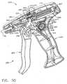
- the surgical instrument or fastener delivery device of the present inventioncomprises a hand held surgical instrument 35 containing a plurality of surgical fasteners or surgical elements that can be generally used for the attachment of a prosthetic to tissue, or as a tissue marker.
- the surgical fasteners 105 of the present inventionmay be formed from a superelastic nickel titanium alloy, may be stored within the surgical instrument in a compressed or collapsed state, and may expand to an unconstrained state upon release from the surgical instrument. Actuation of the instrument simultaneously releases a fastener 105 of the present invention from a distal end of the instrument and indexes the plurality of fasteners 105 within the instrument.
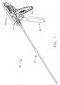
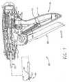
- Surgical instrument 35 of the present inventionhas a handle 40, an elongated shaft 92 extending distally from the handle 40, and a trigger 85 extending downwardly from the handle 40.
- Handle 40has a right half 41 and a left half 42 that may be generally mirror images of each other and, in FIGS. 1 and 2, the left half 42 is omitted.
- Elongated shaft 92may be fixedly attached to the handle 40, and can be formed from a rigid hollow material such as stainless steel tubing.
- a grip 43can be fixedly attached to and extends downwardly from a proximal end of handle 40 and adjacent to the trigger 85.
- Trigger 85pivotably mounts within handle 40 and can be moveable from an open position as shown in FIG. 1 to a closed position adjacent to the grip 43 as shown in FIG. 2. Movement of the trigger 85 to the closed position extends an end effector 95 from a distal end of the shaft 92 (FIG. 2) for the placement and release of a fastener.
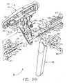
- FIG. 2Bis an isometric exploded view of the majority of the elements found within the surgical instrument 35.
- the exploded viewis provided to familiarize the reader with the key elements contained therein, and the method of assembly used to form the surgical instrument 35.
- a number of elementssuch as the left handle half 42 can be removed.
- Some of the elements of FIG. 2Bmay be complex in shape and the reader may be advised to return to this figure for identification or comprehension of features referenced below.
- the elements of the surgical instrument 35may be contained within the right and left handle halves 41,42 which can be formed from an engineering thermoplastic such as styrene, polycarbonate, or any one of a number of suitable materials.
- a shaft slot 44may be located at the distal end of the upper portion of the handle halves 41,42 for the reception and retention of the shaft 92 therein.
- a latch slot 45may be located proximally to and below the shaft slot 44 within the right handle half 41.
- Latch slot 45may be right-angled in shape and may be provided for the reception of a latch 55 therein.
- Latch 55can have a rigid latch post 57 at a distal end and a right-angled beam 56 extending distally therefrom.
- Beam 56may be formed from a resilient spring material such as stainless steel.
- a distal end of beam 56may be captured and held within the latch slot 45 with a significant amount of the beam 56 cantilevering therefrom.
- the cantilever portion of the beam 56enables the latch post 57 to move freely up and down as the beam 56 deflects. The significance of the latch 55 will be described later.
- a first and a second slider 60, 70may be opposing members that extend generally proximally and distally throughout the shaft 92 and handle 40 of the surgical instrument 35 and form a drive mechanism for the fasteners 105.
- First and second sliders 60, 70may be moveable proximally and distally with respect to the surgical instrument 35 and individually with respect to each other, and may be slidably retained within a pair of guide slots 46 located within each of the handle halves 41, 42.
- the first and second sliders 60, 70have a proximal and a distal end and are shown spaced apart prior to assembly to show a plurality of fasteners 105 that may be stored therebetween.
- Fasteners 105can extend along the entire length of the first and second sliders 60, 70.
- First and second sliders 60, 70can have distal first and second feed members 61, 71 that slidably mount within the shaft 92, and can have a larger proximal first and second sequencing member 62, 72 that slidably mount within the handle halves 41, 42.
- First and second feed members 61, 71may be semi-circular in cross section and can have a first and second outer surface 64, 74.
- a pair of first and second stab posts 64a, 74acan extend outwardly from a distal end of each first and second outer surface 64, 74 respectively.
- a first and second contact surface 63, 73can complete the semi-circular cross section of the first and second feed members 61, 71 respectively.
- First and second contact surfaces 63, 73can opposably face each other along the entire length of the first and second sliders 60, 70 and can have a first and second fastener channel 65, 75 extending therein.
- first and second sliders 60, 70can make sliding contact along the entire length of first and second contact surfaces 63, 73 and first and second fastener channels 65, 75 can form a hollow rectangular channel for the holding and feeding of fasteners 105 serially therethrough (FIG. 15).
- the fastener channels 65, 75 of the first and second sliders 60, 70may be "U" shaped for the reception of the fasteners 105 therein and can have a pair of opposed inner surfaces or channel floors for engaging with the fasteners 105.
- the inner surfacescan have a plurality of projections or fastener drive features spaced thereon for engagement with the fasteners 105.
- these projections or sawteeth 120can extend proximally to distally along the entire length of the floors of the first and second fastener channels 65, 75 and may be equally spaced a longitudinal distance "D" apart.
- the distance "D"may be between 8 inches and .005 inches.
- the spacing "D" of the present inventionmay be .475 inches.
- the spacing "D”can space the fasteners apart from one another so that the fasteners do not engage or touch as they are fed within the surgical instrument 35.
- Each sawtooth 120can have a proximal incline 122 and a distal step 121 as shown. The role of the sawteeth 120 in the feeding of the fasteners 105 will be discussed in detail later.
- first and second fastener guide 66, 76respectively which may be a tapered lead-in at the proximal end of fastener channels 65, 75 and can assist in the loading of the fasteners 105 therein.
- These fastener guides 66, 76may be generally mirror images of each other. In FIG. 2B, the first fastener guide 66 is hidden.
- the larger proximal portions of the first and second sliders 60, 70are the first and second sequencing members 62, 72, which may control the timing and sequencing of a fastener feeding mechanism that releases a fastener from the distal end of the instrument, and indexes or feeds the plurality of fasteners distally within the instrument.
- the first sequencing member 62can have a pair of guide ribs 68 extending laterally outwardly from either side and a first spring stop 67 extending upwardly at a proximal end.
- Guide ribs 68can mount within the guide slots 46 of the right and left handle halves 41, 42 and can slidably secure the assembled sliders 60, 70 within the handle 40.
- a pair of "C" shaped guide channels 69may be located underneath and extend longitudinally along the proximal half of the first sequencing member 62.
- the second sequencing member 72can have second spring stop 77 located at a proximal end of second sequencing member 72 and a forked stop 78 extending upwardly at a distal end.
- a cam plate 79can extend outwardly from the far side of the second sequencing member 72 towards the right handle half 41.
- a pair of slider ribs 83can extends laterally outward along the proximal half of the second sequencing member 72.
- First and second sliders 60, 70can be formed as a single piece from an engineering thermoplastic such as a liquid crystal polymer, a polycarbonate, nylon, a styrene or the like.
- the first and second sliders 60,70may be slidably interlocked together by inserting the pair of slider ribs 83 located on the second sequencing member 72 into the pair of guide channels 69 of the first sequencing member 62.
- First and second sliders 60,70may be made sharp by the attachment of penetrating members or first and second stab plates 96, 97 thereon.
- First and second stab plates 96, 97can be then attached to the first and second sliders 60, 70 by placing first and second stab plates 96, 97 over first and second stab posts 64a, 74a and then placing the assembled stab plates 96, 97 and first and second sliders 60, 70 into the hollow shaft 92 to form a shaft sub-assembly- This method of stab plate retention is best shown in FIG. 14.
- Stab plates 96, 97can be used to pierce tissue during the placement of a fastener 105 into tissue and can be made from a rigid material such as stainless steel.
- the shaft sub-assemblycan be placed into an fastener feeding station (not shown) and the fastener 105 can be fed one at a time into the first and second fastener guides 66, 76 and into the hollow channel formed from fastener channels 65, 75.
- the fastener 105can be inserted until the fastener 105 engages with the feeding mechanism, which will be described later.
- the first and second sliders 60, 70can be reciprocated proximally and distally relative to one another to feed or index the fastener 105 further into the shaft sub-assembly.
- This processcan be repeated for each new fastener 105 until the first and second sliders 60, 70 are fully loaded with a plurality of fasteners 105 in a serial fashion.
- the plurality of fasteners 105can be equally spaced along the entire length of the first and second sliders 50, 60.
- the shaft sub-assembly containing the fastener 105may be then placed into the right handle half 41.
- Shaft 92can be received in shaft slot 44 and the guide ribs 68 of the first slider 60 may be slidably placed into the guide slot 46.
- a lockout wheel 100may be placed into a wheel receptacle 48 located within the right handle half 41 at a position proximal to the pivot bore 47.
- a trigger assemblycan be constructed by placing a trigger plate 87 and a lockout arm 88 over a pivot 86 that extends laterally on either side of trigger 85 and fixably attaching them to trigger 85 with a pair of pins 89.
- a drive arm 90can extend upwardly from the trigger plate 87 and a spring post 91 can extend from the far side of the trigger plate 87 towards the right handle half 41.
- An end of a trigger spring 104(FIG. 3) can be then placed over spring post 91.
- the trigger assemblymay be then placed into the right handle half 41 by placing the far side pivot 86 (not shown) into a pivot bore 47.
- Trigger 85, trigger plate 87, and lockout arm 88are shown as separate pieces but can alternately be constructed as a single piece from an engineering thermoplastic such as polycarbonate, styrene or the like.
- FIG. 3shows the fully assembled elements of the handle 40.
- the free end of the trigger spring 104has been stretched and attached to a spring pin 49 of the grip 43.
- the attachment of the free end of the trigger spring 104tensions trigger spring 104, and biases the trigger 85 to the open position shown.
- a first return spring 115may be compressed and placed into a first spring pocket formed between the first spring stop 67 of the first slider 60 and a first spring rib 50 of the handle halves 41, 42.
- a second return spring 116may be also compressed and placed into a second spring pocket formed between the second spring stop 77 of the second slider 70 and a second spring rib 51.
- the left handle half 42may be attached to the right handle half 41 to complete the assembly of the surgical instrument 35. The left handle half 42 has been removed for clarity.
- the instrument of FIGS. 3-8shows the operation of the actuator or sequencing mechanism that can control the timing and movement of elements within the surgical instrument 35.
- the actuator mechanismcan be engaged by the actuation of the trigger 85 and moves the drive mechanism or first and second sliders 60,70 into at least three sequential positions. Actuation of the trigger 85 can simultaneously move the first and second sliders 60, 70 distally from a first proximal position to a second distal position, then returns the first slider 60 to the proximal position, and finally returns the second slider 70 to the proximal position.
- This sequence of motioncan advances the plurality of fasteners 105 distally, and deploys the distal end of the fastener into tissue in two steps.
- the actuator mechanismcan consists of the latch 55; the trigger assembly described above, the first and second return springs 115, 116, and the first and second sliders 60, 70.
- FIG. 3shows a first or left side view of the surgical instrument of FIG. 1 with the right handle half 41 in place, the left handle half 42 removed for clarity, and the trigger 85 in the initial open position.
- the first and second sliders and second return springs 115, 116can bias the first and second sliders 60, 70 distally within the handles 41, 42.
- the trigger 85 of the trigger assemblycan be in the full open position with the drive arm 90 poised to operatively engage a proximal end of the guide rib 68 of the first sequencing member 62.
- First and second sliders 60, 70are in the first proximal position.
- FIG. 4shows the second or right side view of the surgical instrument of FIG. 3 with the left handle half 42 in place and with the right handle half 41 removed.
- the latch 55is visible in this view, and the latch post 57 of latch 55 may be operatively engaged with a first ramp 69a located on the distal end of the first sequencing member 62.
- a portion of the first and second spring ribs 50, 51 and the latch slot 45 of the right handle half 41are shown in cross-section for clarity.
- FIGS. 5 and 6show the left and right side views of the assembled surgical instrument 35 respectively, and show the first and second sliders 60, 70 can be translated or moved distally from the first position of FIGS. 3-4 to the second position by the trigger 85.
- the distal movement of first and second sliders 60, 70can extend the end effector 95 from the distal end of the shaft 92-
- the trigger 85is in a first partially closed position and may be poised to release the first slider 60 from the drive arm 90 of the trigger assembly.
- the drive arm 90can rotate into operative engagement with the guide rib 68 and move the first slider 60 distally.
- the forked stops 78 of the second slider 70may be contacted, pushing the second slider 70 distally.
- the distally moving first and second sliders 60, 70can compress the first and second return springs 115, 116 as shown.
- the lockout arm 88 of the trigger assemblyis moving upwardly, and can rotating the lockout wheel 100.
- first and second sliders 60, 70move distally, they can deflect the latch post 57 of the latch 55 downwardly to slide along the first ramp 69a of the first slider 60 and a second ramp 80 of the second slider 70.
- Latch post 57 of the latch 55can pass the second ramp 80 and deflect upwardly to lock against a third ramp 81 of the second slider 70 and against a bottom surface 62a of the first sequencing member 62. With the latch 55 in this position, the second slider 70 can be locked in the distal position and cannot move proximally.
- FIGS. 7 and 8show the left and right side views of the assembled surgical instrument 35 respectively, after the first slider 60 has reciprocated or returned back to the first proximal position of FIGS. 3 and 4 to partially release a fastener 105 from the end effector 95.
- the first slider 60reciprocates distally to the first proximal position from the second distal position shown in FIGS. 5 and 6.
- Slider 60may be returned to the proximal position by first return spring 115.
- the proximal movement of the first slider 60can retract the first stab plate 96 proximally into the shaft 92 and release a distal end of the fastener 105 as shown.
- the lockout arm 88can move upwardly from and disengaged with the lockout wheel 100.
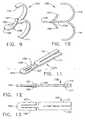
- FIGS. 9-13are expanded views showing the novel surgical element, anchor, or fastener 105 of the present invention.
- a plurality of fasteners 105 of the present inventionare contained serially within the surgical instrument 35 (FIG. 2B) and are used to fasten or suture a prosthetic such as a surgical mesh pad onto tissue.
- the fastener 105 of the present inventionmay be elastic and is shown in its original unconstrained state in FIGS. 9 and 10. When fastener 105 may be distorted or constrained, it will return to its original shape when released.
- Fastener 105can be formed or stamped from a sheet or foil of a pseudoelastic or superelastic nickel titanium alloy to take advantage of pseudoelastic or superelastic properties thereof, or an elastic or spring grade of steel, stainless steel, copper, or other titanium alloys.
- fastener 105may be made from an alloy comprising from about 50.5% (as used herein these percentages refer to atomic percentages) Ni to about 60% Ni, and most preferably about 55% Ni, with the remainder of the alloy Ti.
- the fastenermay be such that it may be superelastic at body temperature, and preferably has an Af in the range from about 15° C to about 37° C. The superelastic design of the fastener 105 makes it crush recoverable which makes it possible to store a large fastener 105 within a small diameter shaft 92.
- fastener 105 of the present inventionmay be made from a superelastic alloy and can be made of an alloy material having greater than 50.5 atomic % Nickel and the balance titanium. Greater than 50.5 atomic % Nickel allows for an alloy in which the temperature at which the martensite phase transforms completely to the austenite phase (the Af temperature) may be below human body temperature and may be about 15° C to about 37°C so that austenite may be the only stable phase at body temperature.
- the unconstrained fastener 105 of FIGS. 9 and 10can have a generally planar continuous body member 109 having a first (distal) end and a second (proximal) end. At least one barb can extend from the distal end, and at least two barbs extend from the proximal end.
- the continuous body member 109can have a distal tip 106 which may be rounded or blunt. Alternately, the distal tip 106 of the fastener 105 can be made sharp or pointed if desired.
- a first and a second barb 107,108can extend proximally and axially away from the distal tip 106 and away from the body member 109. The first and second barbs 107, 108 can be curved.
- the distal end of the body member 109can a pair of barbs or a first and a second leg 110,111 that extend distally from the body member 109 and away from each other in different directions.
- First and second legs 110,111 of the present inventionmay engage the inner surfaces of the first and second members 60,70, can also be curved outwardly from the body member 109, and can form the everted configuration f FIGS. 9 and 10.
- the ends of the first and second barb 107,108, and first and second leg 110, 111can be blunt.
- FIGS. 11-13shows an isometric view, a side view, and a bottom view of the fastener 105 of the present invention wherein the fastener 105 is shown in a constrained state that the fastener 105 assumes when stored within the surgical instrument 35 (FIG. 1).
- the fastener 105can revert to the unconstrained shape of FIGS. 9 and 10 when released from the surgical instrument 35.
- Surgical fastener 105can also be used as a marker when placed in tissue- That is, the material of the fastener 105 may be such that it appears in diagnostic tests such as MRI scans, CAT scans, X-rays, or ultrasound, and the surgeon can readily identify the location of the fastener relative to other body features.
- FIGS. 14 and 15are enlarged partial cross-sectional views of the distal end of the shaft 92 of FIG. 3 showing the first and second sliders 60,70 or walking beams at the first or un-actuated position wherein they are recessed into the shaft 92, and the fasteners 105 contained therebetween.
- the trigger 85 of the surgical instrument 35may be fully open (FIG. 3) and the sawteeth 120 of the first slider 60 may be lined up with and directly opposed from the sawteeth 120 within the second slider 70.
- FIG. 15shows how the first and second fastener channels 65, 75 can form a passageway for the reception of the fasteners 105 therein.
- the drive mechanismuses the fasteners 105 themselves as a part of the drive mechanism.
- the drive mechanism 59can have three distinct elements: the first member or slider 60, the second member or slider 70, and the plurality of fasteners 105 stored in a serial fashion therebetween.
- Fasteners 105may be held between the sawteeth 120 with the barbs 107, 108 deflecting outwardly to center the fasteners 105 between the sawteeth 120.
- First and second legs 110, 111 of the fasteners 105may be biased outwardly, contacting the surfaces of the sawteeth 120 at an angle as shown.
- the corners of the legs 110, 111 where they contact the first and second sliders 60,70can dig into and attempt to expand outwardly against the sawteeth if the fasteners 120 are moved proximally relative to the first or second slider. Also the distal ends of the legs can form positive contact with the steps 121 of the sawteeth 120. Distal movements of the fasteners within the first and second sliders 60,70 can slide the corners of the legs 110, 111 along the inclines 122. Additionally, the corners of the barbs 107, 108 contact the inclines 122 and can act in a similar manner as the legs 110, 111 when they engage the first and second sliders 60,70.
- the distal ends of the first and second legs 110, 111are shown positioned within the pockets at the junction of the step 121 and the incline 122, and are operatively engaged with the steps 121 and slidingly engaged with the inclines 122. It can be the positive contact or engagement of the fasteners 105 with the steps 121 and sliding contact or engagement with the inclines 122 that drives or feeds the plurality of fasteners 105 between the reciprocating first and second sliders 60,70 and places the fastener 105 into tissue. Thus, both the barbs 107, 108 and the legs 110, 111 can propel the fasteners.
- distal movement of both of the first and second sliders 60, 70can result in operative engagement of the fasteners 105 with the steps 121 of both sliders 60, 70.
- This operative engagement with the distally moving sliders 60, 60can result in distal movement of the fasteners 105. If one of the sliders such as first slider 60 is moved distally while the other remains stationary, the fasteners 105 may operably couple with and move with the moving slider 60, while slidingly engaging with the stationary slider 70. And, if one of the sliders such as first slider 60 moves proximally while the other remains stationary, the fasteners 105 can operatively engage with the stationary slider 70 and remain stationary and slidably engaged with the moving slider 60.
- the actuator mechanism of the present inventioncan have at least three sequential positions.
- First, the actuator mechanismcan move the first and second sliders 60, 70 distally (FIGS. 18, 19) from a first proximal position (FIG. 14) to a second distal position (FIG. 19). This movement can positively engage the fasteners 105 with the first and second sliders 60, 70 and move the fasteners 105 distally from the first position to the second position. Moving both the first and second sliders 60, 70 (FIG. 14) from a first proximal position to a second distal position to move the entire plurality of fasteners 105 distally within the surgical instrument 35. That is, each fastener 105 (with the exception of the distal most fastener 105) may now occupies the position of the preceding fastener 105.
- the actuator mechanismcan move or reciprocate the first slider 60 proximally from the second distal position back to the first proximal position to opposedly align the sawteeth 120 of the first and second sliders 60, 70.
- the fasteners 105may be operatively engaged with the stationary second slider 70 and remain stationary (longitudinally) within the shaft 92.
- the actuator mechanismcan move or reciprocate the second slider 70 proximally from the second distal position back to the first proximal position, and may realign the sawteeth 120 within the first and second sliders 60, 70.
- the fasteners 105can be in operative contact with the stationary first slider 60 and remain stationary and in sliding contact with the distally moving second slider 70.
- the first and second sliders 60, 70can place the distal most fastener 105 within tissue and can move distally back to the first position.
- a new fastener 105is shown within first and second sliders 60, 70, ready for placement within tissue.
- the sequence of motionmay be to fix one of the first or sliders such as first slider 60 and to reciprocate the remaining slider 70 distal ly from the first position to the second position and back to the first position.
- the sequence of motionmay be altered wherein the first and second sliders 60, 70 are reciprocated in opposite directions at the same time.
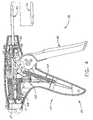
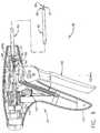
- FIGS. 30-37shows an alternate surgical instrument 235 of the present invention that uses the second embodiment of the drive mechanism described above wherein one of the sliders may be fixed, and one of the sliders reciprocates or moves to drive the fasteners 105 distally through the alternate surgical instrument 235. It is the relative motion between one moving slider and one fixed slider that can move the fasteners 105 distally, and either slider can be the moving slider as long as the remaining slider is fixed. To avoid confusion with the previously described elements such as sliders 60, 70, the changed elements of the alternate feeding mechanism 259 will be given new element numbers and descriptions where required.
- the upper sliderwill be referred to as moving slider 260 and the lower slider will be referred to as fixed slider 270.
- the alternate feeding mechanism 259can have three distinct elements: the moving slider 260, the fixed slider 270, and the plurality of fasteners 105 stored in a serial fashion in channels (FIGS. 34-37) therebetween. Due to the motion and sequencing differences, some additional mechanical differences and method of fastener placement can be required with the alternate feeding mechanism 259. These differences will be described below.
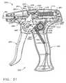
- FIGS. 30-32shows an alternate handle 240 of the alternate surgical instrument 235 and the elements thereof.
- a left alternate handle half 242 of the alternate handle 240has been omitted (i.e. not shown) so the placement and movement of the elements within a right alternate handle half 241 can be seen.
- FIGS. 34-37show the movement of the sliders and other elements in a distal end of the alternate surgical instrument 235 as a fastener 105 may be applied to attach hernia mesh to tissue.
- FIG. 33shows an alternate embodiment of a trigger lockout mechanism.
- the moving slider 260may be located above the fixed slider 270 in the right alternate handle half 241 and extend distally into the tube 92 extending from a distal end of the alternate handle 240.
- First return spring 115can bias the moving slider 260 proximally to the position shown in FIGS. 30-31 by pushing against a moving spring stop 267 of the moving slider 260.
- Moving slider 260may be moveable distally within the alternate surgical instrument 235 by an alternate trigger 285 pivotably mounted within the alternate handle 240.
- Alternate trigger 285can pivot around a pair of opposed alternate pivots 286 to bring an alternate drive arm 287 into contact with a guide rib 268 extending outwardly from the moving slider 260.
- Movement of the alternate trigger 285 from a first open position (FIG. 30-31) to a second closed position (FIG. 32)can move the moving slider 260 and fasteners 105 from a proximalmost position shown in FIGS. 30-31 to a distalmost position shown in FIG. 32.
- This motioncan compress the first return spring 115 between the right alternate handle 241 and stretch a trigger spring 104. attached to the alternate trigger 285 and right alternate handle 241 (FIG. 32).
- Release of the alternate trigger 285 from the second closed positioncan enable the compressed first return spring 115 to return the moving slider 260 to the proximalmost position and the trigger spring 104 to return the alternate trigger 285 to the first open position.
- a fixed stop 277can extend downwardly from a proximal end of the fixed slider 270.
- Fixed stop 277can be captured within a slot 250 of the right alternate handle half 241 and can substantially restrain the fixed slider 270 from proximal and distal motion, thereby "fixing" the fixed slider 270.
- a governor 215may be fixedly attached to a governor socket 264 on the moving slider 260 and can ensure one way movement of the alternate trigger 285 as it moves from the first open position to the second closed position. Once the alternate trigger 285 is fully closed, the governor 215 may be reset and ensure one way movement of the alternate trigger 285 as it moves from the second closed position and back to the fully open position. The actions of the governor 215 can ensure full proximal and distal reciprocation of the moving slider 260 relative to the fixed slider 270 and the advancement of the fasteners 105 therebetween.
- the governor 215may be a spring and can have governor blades 216 extending laterally outward from a proximal end of the governor 215 to operatively engage with at least one governor rack 244 extending inwardly from the alternate handle 240.
- Governor rack 244can be an inward extension of the plastic handle halves 241,242 or can be one or more pieces fixedly attached to the alternate handle 240.
- Onemay think of the governor as a mechanism which prevents the actuator from moving to the second position, after initially moving to the first position, until the actuator has fully moved to its first position, and from moving to the first position, after initially moving to the second position, until the actuator has fully moved to its second position.
- the governor 215is shown deflecting upwardly and below the governor rack 244.
- the governor 215may be moved distally and may be deflected downwardly by the governor rack 244.
- This motioncan bring an upper edge of the governor blades 216 into contact with a lower rack 245 of rack sawteeth 247.
- the rack sawteeth 247can be oriented to provide one way sliding engagement with the governor blades 216 during the full distal advancement of the moving slider 260 and the fasteners 105, and locking engagement if the moving slider 260 may be moved proximally by opening the alternate trigger 285.
- the alternate trigger 285is fully closed and the governor 21 may be reset upwardly by sliding out from under the lower rack 245.
- the moving slider 260may move proximally to bring a lower edge of the governor blades 216 into contact with an upper rack 246 of the governor rack.
- the rack sawteeth 247 of the upper rack 246may be oriented to provide one way sliding action with the governor blades 216 as the alternate trigger 285 moves from the closed position to the open position and to lockingly engage if the trigger 285 moves back towards the closed position.
- the governor rack 244can be an inward extension of the plastic alternate handle 240 or can be a secondary part formed of an alternate material such as a metallic or a plastic.
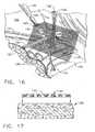
- one typical application of the surgical instrument of the present inventionmay be a repair of a defect, such as an inguinal hernia 125, located in inguinal tissue such as the inguinal floor 126.
- a defectsuch as an inguinal hernia 125
- inguinal tissuesuch as the inguinal floor 126.
- the anatomical structures of the left inguinal anatomy of a human patientare illustrated in order to point out the usefulness of the present invention.
- the inguinal hernia 125may be accessible through iliacus muscle 127.
- a network of vessels and nervesexist in the area of a typical inguinal hernia 125, which requires a surgeon to conduct a hernia repair with great skill and caution.
- an internal ring 129permits gastric vessels 130 and Vas deferens 131 to extend therethrough over an edge of inguinal ligament 132.
- Femoral canal 133is located near Cooper's ligament 134 and contains external iliac vessels 135 and inferior epigastric vessels 136.
- the edge of the inguinal ligament 132 and Cooper's ligament 134serve as anatomical landmarks and support structures for supporting surgical fasteners such as those mentioned previously.
- the area containing the external iliac vessels 135 and the Vas deferens 131may be commonly known as "the Triangle of Doom" to surgeons. Accordingly, the surgeon should avoid injuring any of these vessels described above and care must be taken when performing dissection, suturing or fastening within this area.
- a prosthetic or a mesh patch 140may be placed over the inguinal hernia 125 with a surgical grasping instrument 145 as the first step in the repair of the inguinal hernia 125.
- the mesh patch 140may consist of any desired configuration, structure or material.
- the mesh patch 140may be preferably made of PROLENE TM (a known polymer made up of fibers) and preferably configured as mesh. It may be within the training and comfort zone for surgeons to use the PROLENE TM mesh patch 140 since the mesh patch 140 may be easily sized, such as providing a side slot 141, for accommodating the gastric vessels 130 and the Vas deferens 131.
- the mesh patch 140may be placeable over the inguinal hernia 125 for providing a sufficient barrier to internal viscera (not shown) of the abdomen which would otherwise have a tendency to protrude through the inguinal hernia 125 and cause the patient a great deal of pain and discomfort.
- FIG. 17shows a side view of the mesh patch 140 being placed onto the inguinal floor 126. The mesh patch 140 may be now attachable to the inguinal floor 126.
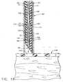
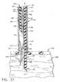
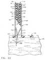
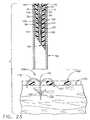
- FIGS. 18-23are also used to illustrate the method of use of the surgical instrument 35. These cross-sectional side views of the distal end of the shaft 92 show the steps involved in using the surgical instrument 35 as it places a novel fastener 105 of the present invention into the inguinal floor 126 to attach the mesh patch 140 thereto.
- FIG. 18is a cross-sectional side view of the inguinal floor 126 of the lower abdomen wherein the surgeon has placed the distal end of the shaft 92 into the area near the patient's inguinal hernia 125. The surgeon has selected an attachment point or surgical site and is using the distal end of the surgical instrument 35 to push the mesh patch 140 downward onto the inguinal floor 126. The distal end of the shaft 92 may be deliberately positioned over an opening 142 within the mesh patch 140 for the placement of a fastener 105 therethrough. The position of the end effector 95 within the cross-sectioned shaft 92 indicates that the trigger 85 has been partially activated by the surgeon. The partial movement or activation of the trigger 85 can translate or move the first and second sliders 60, 70 distally (downwardly in FIG. 18) from the initial position shown in FIG. 14.
- the surgeonhas continued to actuate or move the trigger , 85, to the first position (FIGS. 2, 5, and 6), and has fully extended or translated the first and second sliders 60, 70 of the end effector 95 from the shaft 92.
- the extended end effector 95has penetrated through the opening 142 within the mesh patch 140 and into the inguinal floor 126.
- the first and second barbs 107, 108 of the distal most fastener 105are placed within tissue of the inguinal floor 126.
- the indexing mechanism of the surgical instrument 35may be actuated and an automatic sequence of actions occurs beginning with the reciprocation or movement of the first slider 60 proximally as indicated by the arrow in FIG. 20.
- the first slider 60has partially moved or retracted into the shaft 92- This action can released the first and second barbs 107, 108 of the distal most fastener 105 from the constrained condition shown in FIG. 19 and fixably engaged the first barb 107 with the tissue of the inguinal floor 126.
- the barbs 107, 108 of the distal fastener 105when released, can snap open to the positions shown in FIG. 20, bending the distal most fastener 105.
- the first slider 60can continue to move distally into the surgical instrument 35 until it returns to the to the initial start position within the shaft 92 as shown in FIG 21.
- the second slider 70may be automatically released to move or reciprocate distally into the shaft 92 as indicated by the arrow.
- the first slider 60is the initial start position of FIG. 15, and can fully release the distal fastener 105.
- the second barb 108 and second leg 111may bias the distal fastener 105 into the portion of the shaft 92 previously occupied by the first feed member 61 of the first slider 60. This bias can further engage the first barb 107 of the distal fastener 105 with the inguinal floor 126.
- the second slider 70has automatically retracted distally into the shaft 92 to the first start position and can fully release the second barb 108 of the distal fastener 105 to engage with the tissue of the inguinal floor 126.
- the second leg 111 of the distal fastener 105can be released from the second slider 70 and both the first and the second legs 110, 111 can expand outwardly within the shaft 92.
- the surgeoncan release the trigger 85 which returns to the initial open position of FIG. 1 and withdraws the distal end of the shaft 92 away from the mesh patch 140, and from the distal fastener 105 that may be engaged or attached to the inguinal floor 126.
- the first and second barbs 107, 108 of the fastener 105 of the present inventionare firmly planted within the inguinal floor 126 and the first and second legs 110, 111 may when released from the shaft 92, snap back to their original everted shape (FIGS. 9 and 10).
- the mesh patch 140may be fixedly held against the inguinal floor 126 by the first and second legs 110, 111 of the fastener 105.
- the surgical instrumentis now ready to attach the mesh patch 140 at another site.
- the surgeonmerely repositions the distal end of the shaft 92 at another surgical site and actuates the trigger 85 to place or attach another fastener 105 into the inguinal floor 126. This process may be continued until the mesh patch 140 is satisfactorily attached to the inguinal floor 126.
- FIGS. 34-37illustrate the method of use of the alternate surgical instrument 235 as it attaches a mesh patch 140 to the inguinal floor 126 with a fastener 105.
- alternate surgical instrument 235can have one moving slider 260 and one fixed slider 270. This configuration may use a different sequencing or movement method to place the fastener 105 into tissue.
- the previously described sliders 60, 70can have internal fastener channels 65, 75 (FIG. 28) to propel the fasteners 105 through the surgical instrument 35.
- the moving and fixed sliders 260,270can use the same principle and may have a moving channel 265 in the moving slider 260 and a fixed channel 275 in the fixed slider 270.
- the moving and fixed channels 265, 275can also have sawteeth 120 with steps 121 and inclines 122.
- the longitudinal distance between the steps 121can be halved in the alternate surgical instrument 235 while the length of the reciprocation stroke can remain generally the same as the stroke in the surgical instrument 35.
- the fastener 105may be generally moved distally the same distance in either surgical instrument 35, 235.
- the second leg 111 of the fastener 105may be moved distally two sawteeth as the shown by the distalmost fastener 105 as it moves from the position of FIG. 34 to the position of FIG. 35.
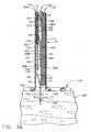
- FIG. 34shows a cross-sectional side view of the inguinal floor 126 of the lower abdomen wherein the surgeon can use a distal end of the shaft 92 of the alternate surgical instrument 235 to push a mesh patch 140 downwardly against the inguinal floor 126.
- the distal end of the shaft 92may be deliberately positioned over an opening 142 within the mesh patch 140 for the placement of a fastener 105 therethrough.
- the alternate trigger 285is in the first open position (FIG. 31) and the moving slider 260 can be in the proximal most position-
- the fixed slider 270is fixed relative to the shaft 92, and the moving slider 260 may be poised to propel the fasteners 105 distally and the distalmost fastener 105 (shown on bottom) into tissue.
- the second legs 111 of the fasteners 105can be in contact with a step 121 of the fixed slider 270. As shown, a small amount of distal (downward) motion of the moving slider 260 may bring a step 121 of the moving slider 260 into contact with the first leg 110 of the fasteners 105.
- a moving stab plate 296may be fixedly attached to the moving slider 260 and is best shown in FIG. 35. Moving stab plate 296 may be a stepped cylinder having two different diameter sections, a large diameter proximal section 297 and may be fixedly attached to the moving slider 260 with a small diameter distal section 298 extending distally therefrom. Distal section 298 has a piercing point 299 at a distal end that can penetrate tissue.
- a slot 300can extend longitudinally through proximal section 297 and distal section 298 to provide clearance around a proximal end of the fixed slider 270.
- the distalmost fastener 105may be located within the moving stab plate 296 with the first barb 107 in contact with an inner surface of the distal section 298 and the second barb 108 in contact with the fixed slider 270.
- the distalmost portion of the fixed slider 270may be located within the slot 300.
- FIG- 35shows the effects of moving the alternate trigger 28 from the first open position to the second closed position.
- An arrowis provided to show the direction of motion.
- This actioncan move the moving slider 260 and the fasteners 105 distally to the distalmost position.
- the moving stab plate 296may pierce the mesh patch 140 and the inguinal floor 126 to place the distal section 298 of the moving stab plate 296 into tissue.
- the barbs 107,108can be constrained from outward movement by contact with the inner surface of the distal section 298.
- the first leg 110 of the fastener 105may be operatively engaged with the distalmost step 121 of the moving slider 260 to hold distalmost fastener 105 in the position shown.
- the alternate trigger 285 of the alternate surgical instrument 285has been released and the moving slider 260 has returned proximally (see arrow) to the proximal most position (FIGS. 34, 37).
- the moving slider 260can move the fasteners 105 proximally a slight amount. This proximal motion may bring an end of each of the second legs 111 of the fasteners 105 into contact with a respective step 121 of the fixed slider 270 and can prevent additional proximal motion of the fasteners 105.
- the proximal motion of the moving stab plate 296 back into the shaft 92can release the first and second barbs 107, 108 of the distalmost fastener 105 from contact with the fixed slider 270.
- the first and second barbs 107. 108may fully deploy to the position shown to retain the distalmost fastener 105 in tissue.
- the first and second legs 110,111 of the distalmost fastener 105may be held in the constrained position shown between the shaft 92 and the distalmost sawtooth 120 of the fixed slider 270.
- the surgeonis moving the surgical instrument proximally (see arrow) away from the mesh patch 140 and inguinal floor 126.
- the distalmost fastenermay be retained within the inguinal floor by the barbs 107,108 and the proximal motion of the alternate surgical instrument 235 can withdraw the first and second legs 110,111 of the distalmost fastener from the shaft 92.
- the first and second legs 110,111 of the fastener 105can snap back to the original everted shape (FIGS. 9 and 10) to secure the mesh patch 140 to the inguinal floor.
- the mesh patch 140may be fixedly held against the inguinal floor 126 by the first and second legs 110, 111 of the fastener 105.
- the alternate surgical instrument 235can now ready to attach the mesh patch 140 at another site. To accomplish this, the surgeon merely repositions the distal end of the shaft 92 at another surgical site and actuates the alternate trigger 285 to place or attach another fastener 105 into the inguinal floor 126. This process is continued until the mesh patch 140 may be satisfactorily attached to the inguinal floor 126
- the surgical instrument 35 of the present inventioncontains a plurality of fasteners 105. As the surgeon repeatedly fires the instrument during the attachment of the prosthetic, the number of fasteners 105 stored therein steadily decreases. When the final fastener 105 is placed into tissue, the surgeon has no way of knowing when the instrument is emptied of fasteners 105 and can attempt to fire the empty surgical instrument 35 on tissue.
- a lockout mechanismmay be provided within the surgical instrument 35 to lock the trigger 85 when the surgical instrument 35 is empty.
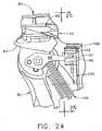
- the trigger 85can have a lockout arm 88 fixably attached to and extending therefrom. Actuation of the trigger 85 may move the lockout arm 88 from the initial position of FIG. 3 to a first partially closed position within the handle 40, and into contact with the lockout wheel 100 rotatably mounted within the wheel receptacle 48 as shown in FIG. 24.
- the trigger 85has rotated lockout arm 88 counter-clockwise to engage with a tooth 101 of the lockout wheel 100.
- a lockout tab 102can be located just above the lockout arm 88 and extends outwardly from the lockout wheel 100.
- a lockout detent 103can be attached to and extends outwardly from the right handle half 41 towards the viewer to operably engage with the lockout wheel 100.
- a small cutoutcan be provided within the lower portion of the lockout wheel 100 to show the outwardly extending end of the lockout detent 103.
- FIG. 25is a distal view taken across cross-section 25-25 in FIG. 24, and shows the necessary portions of the key elements so that the reader can understand the operation of the lockout mechanism.
- the lockout mechanism of the present inventionmay comprise the lockout wheel 100, the lockout detent 103 and the lockout arm 88 extending from the trigger 85.
- Lockout wheel 100is shown perpendicular to the axis of rotation and can have lockout detent 103 operably engaged with a lockout tooth 101 to prevent clockwise rotation of the lockout wheel 100.
- the lockout armis cross-sectioned by the cutting plane 25-25 and two cross-sections are taken across the lockout arm 88.
- a first section 88acan be taken across the distal end of the lockout arm 88 when the lockout arm is in the initial position, and a second section 88b can be taken across the lockout arm 88 to show the actual position of the lockout arm 88.
- An arrowis provided to identify the direction of motion of the second section 88b of the lockout arm 88.
- the lockout wheel 100 of the present inventioncan have the same number of teeth 101 around its circumference as the surgical instrument 35 has fasteners 105.
- the lockout arm 88can be brought into contact with the lockout wheel 100 to rotate or index the lockout wheel 100 counter-clockwise one tooth 101 as shown in FIG. 26.
- the lockout detent 103can prevent the lockout wheel 100 from rotating clockwise as the lockout arm 88 returns to the initial position 88a.
- one full actuation of the trigger 85can rotate the locking wheel 100 one tooth 101, and firing all of the fasteners 105 can rotate the lockout wheel 100 one full revolution.
- FIGURES 27-29show how the lockout tab 102 can operatively lock the lockout arm 88 (and the trigger 85) in the fully actuated or closed position as the last fastener 105 can be fired.
- the lockout wheelhas rotated nearly one full revolution from the first position of FIG. 25. This is indicated by the new position of the lockout tab 102.
- the second section 88b of the lockout arm 88is shown moving upwardly, has just cleared the lockout tab 102, and can be contacting the final lockout tooth 101.
- the second section 88b of the lockout arm 88can be shown in the fully actuated or closed position and the lockout tab 102 can rotate in under the second section 88b of the lockout arm 88.
- the second section 88b of the lockout arm 88can move downwardly to contact the lockout tab 102 and can rotate the lockout wheel 100 clockwise to engage tooth 101 with the lockout detent 103 (FIG. 29).
- the engagement with the lockout detent 103can prevent the lockout wheel 100 from rotating clockwise and can lock the second section 88b of the lockout arm 88.
- the second section 88b of the lockout arm 88 (and trigger 85)may be locked in the first partially closed position by the lockout detent 103 which prevents the trigger 85 of the surgical instrument 35 from opening.
- FIGS. 31-33show an alternate lockout mechanism and the movement of the elements of the lockout mechanism as the alternate trigger 285 may be fired or reciprocated from the first open position (FIG. 31) to the second closed position (FIG. 32) and back to the first open position (FIG. 33).
- the alternate lockout mechanismprovides many of the same features of the previously described lockout mechanism such as a rotating lockout wheel, but can offer an alternate lockout that locks the alternate trigger 285 in the open position.
- the alternate lockout mechanismcan have a disk-like alternate lockout wheel 205 that mounts in alternate handle 240 and rotates in a counterclockwise direction.
- the alternate lockout wheel 205can comprise a disk face 206 and a plurality of angled counter teeth 207 that extend therefrom.
- the lockout mechanismcan have one angled counter tooth 207 for each fastener 105 stored within the alternate surgical instrument 235.
- a counter slot 208can also be located in the disk face 206 of the alternate lockout wheel 205.
- a one way detent arm 209(FIG. 33) can be located on the backside of the alternate lockout wheel 205 to prevent clockwise rotation of the alternate lockout wheel 205.
- a first marker 206a and a second marker 206bmay be located on the disk face 206 at specific angular locations, the purpose of which will become apparent in the assembly description below.
- Alternate trigger 285,(FIGS 30-33) can be pivotally mounted within the alternate handle 240, and can have an alternate counter arm 288 extending proximally therefrom.
- Alternate counter arm 288can have a proximal end 289 that can operably engage with the alternate lockout wheel 205.
- a lock post 290can extend from a backside of the alternate trigger 285 (FIG. 33).
- a locking member 210can comprise an elongated member having a retainer 211 at a proximal end, a locking tab 212 extending downwardly from the locking member 210, and a locking bore 213 adjacent to a distal end (FIG. 33).
- the locking member 210can be a spring so that it can deflect during operation.
- the lockout mechanismcan be assembled by first capturing the retainer 211 of the locking member 210 in the right alternate handle half 241. Locking member 210 can become a spring cantilever beam extending distally from the capture point. Next, the alternate lockout wheel 205 can be placed onto a post (not shown) extending from the right alternate handle half 241. This placement brings the one way detent arm 209 (FIG. 33) into contact with one of a plurality of detent teeth 248 extending from the right alternate handle half 241 (FIG. 30). The alternate lockout wheel 205 is shown oriented with the first marker 206baligned with the locking tab 212 of the locking member 210.
- This alignment positioncan be used when the alternate surgical instrument holds ten fasteners 105 and can provide ten firings before the lockout may be activated.
- the alternate lockout wheel 205can be oriented with the second marker 206a to provide twenty firings before the lockout may be activated.
- the alternate trigger 285can be placed into the right alternate handle half 241, trigger spring 104 can be connected to the alternate trigger 285 and the right handle half 241 and the left alternate handle half 242 can be attached to secure the alternate locking mechanism and other components. Attachment of the left alternate handle half 242 may push a backside of the disk face 206 of alternate locking wheel 205 into contact with the locking tab 212 of the locking member 210 to deflect a distal end of the locking member 210 inwardly from the contact. This deflection can be best seen in FIG. 33 as the gap between the lock post 290 and the locking member 210.
- the alternate lockout mechanismcan operate as follows. As the alternate trigger 285 is moved from the first open position of FIG. 31 to the second closed position of FIG. 32, the proximal end 289 of the alternate counter arm 288 can deflect up and over the a stationary counter tooth 208a. The counter tooth 208a is shown in FIG. 31 as just above and generally behind the proximal end 289 of the alternate counter arm 288.
- the alternate lockout wheel 285may remain stationary during this action as one way detent arm 209 lockingly engages with one of the plurality of detent teeth 248 (FIG. 30) located in the right alternate handle half 241. This locking engagement can prevent clockwise rotation of the alternate locking wheel 285. Additionally, the one way detent arm 209 can provide sliding action during counterclockwise rotation of the alternate lockout wheel 205.
- the alternate trigger 285may be released to return from the second closed position of FIG. 32 back to the first open position of FIG. 31 and 33.
- the proximal end 289 of the alternate counter arm 288can move back into contact with the previously described counter tooth 208a and push tooth 208a downwardly to the position shown in FIG. 33.
- each firing or reciprocation of the alternate trigger 285can eject one fastener 105 from the alternate surgical instrument 235 and indexes the alternate lockout wheel 205 one tooth.
- an equivalent structure which may be used to implement the present inventionis a feeding mechanism that can distally move a pair of oposed members that move a fastener distally, the distal movement can place the distal end of the fastener into tissue, can partially deploy a distal end of the fastener into tissue by moving one member proximally, and can fully deploy the distal end of the fastener into tissue by moving the remaining member proximally.
- a feeding mechanismcan be provided that can consecutively reciprocate a pair of opposed members in opposite directions to propel the fastener distally, can partially place the distal end of the fastener into tissue with a first reciprocation and can fully place the fastener into tissue with a second reciprocation.
- every structure described abovehas a function and such structure can be referred to as a means for performing that function.
Landscapes
- Health & Medical Sciences (AREA)
- Life Sciences & Earth Sciences (AREA)
- Surgery (AREA)
- Heart & Thoracic Surgery (AREA)
- Engineering & Computer Science (AREA)
- Biomedical Technology (AREA)
- Nuclear Medicine, Radiotherapy & Molecular Imaging (AREA)
- Medical Informatics (AREA)
- Molecular Biology (AREA)
- Animal Behavior & Ethology (AREA)
- General Health & Medical Sciences (AREA)
- Public Health (AREA)
- Veterinary Medicine (AREA)
- Surgical Instruments (AREA)
Abstract
Description
- The present invention relates, in general, to a surgical instrument and, more particularly, to a surgical instrument having a feeding mechanism for feeding at least one surgical fastener from a surgical instrument to attach a prosthetic in the repair of a defect in tissue such as an inguinal hernia.
- An inguinal hernia is a condition where a small loop of bowel or intestine protrudes through a weak place or defect within the lower abdominal muscle wall or groin of a patient. This condition commonly occurs in humans, particularly males. Hernias of this type can be a congenital defect wherein the patient is born with this problem, or can be caused by straining or lifting heavy objects. Heavy lifting may be known to create a large amount of stress upon the abdominal wall and can cause a rupture or tearing at a weak point of the abdominal muscle to create the defect or opening. In any case, the patient can be left with an unsightly bulge of intestinal tissue protruding through the defect, pain, reduced lifting abilities, and in some cases, impaction of the bowel, or possibly other complications if the flow of blood is cut off to the protruding tissue.
- A common solution to this problem can be surgery In the surgical procedure, the defect is accessed and carefully examined, either through an open incision or endoscopically through an access port such as a trocar. In either case, the careful examination can be well appreciated, as a network of vessels and nerves exist in the area of a typical defect, which requires a surgeon to conduct a hernia repair with great skill and caution. Within this area can be found vascular structures such as gastric vessels, the external iliac vessels, and the inferior epigastric vessels, and reproductive vessels such as the vas deferens extending through the inguinal floor.
- Once the surgeon is familiar with the anatomy of a patient, the surgeon carefully pushes the bowel back into the patient's abdomen through the defect. Repairing the defect can involve closure of the defect with sutures or fasteners but generally involves placing a surgical prosthetic such as a mesh patch over the open defect, and attaching the mesh patch to the inguinal floor with conventional suture or with surgical fasteners. The mesh patch acts as a barrier and prevents expulsion of bowel through the defect. Suturing of the mesh patch to the inguinal floor can be well suited to open procedures but can be much more difficult and time consuming with endoscopic procedures. With the adoption of endoscopic surgery, endoscopic surgical instruments that apply surgical fasteners can be used. However, the tissue of the inguinal floor may offer special challenges to the surgeon when a needle or fastener is used to penetrate structures such as Cooper's ligament.
- At present, there are a variety of surgical instruments and fasteners available for the surgeon to use in an endoscopic or open procedure to attach the mesh patch to the inguinal floor. One of the earliest types of endoscopic surgical instruments used is a surgical stapler. A plurality or stack of these unformed staples may be generally contained within a stapling cartridge in a serial fashion, and may be sequentially advanced or fed within the instrument by a spring mechanism. A secondary valving or feeding mechanism may be employed to separate the distal most staple from the stack, to hold the remainder of the spring loaded stack, and may be used to feed the distal most stapler into the staple forming mechanism. Feeding mechanisms of this type are found in
U.S. Patent No. 5,470,010 by Robert Rothfuss et al. and inU.S. Patent No. 5,582,616, also by Robert Rothfuss et al. - Another hernia mesh attachment instrument uses a helical wire fastener that resembles a small section of spring. Multiple helical wire fasteners may be stored serially within the 5mm shaft, and may be corkscrewed or rotated into tissue. A load spring may be used to bias or feed the plurality of helical fasteners distally within the shaft. A protrusion extends into the shaft to possibly prevent the ejection of the stack of fasteners by the load spring and may permit passage of a rotating fastener. Instruments and fasteners of these types are found in
U.S. Patent No. 5,582,616 by Lee Bolduc et al. ,U.S. Patent No. 5,810,882 by Lee Bolduc et al. , and inU.S. Patent No. 5,830,221 by Jeffrey Stein et al. - Whereas the above surgical instruments may be used for hernia fastening applications, they use a spring mechanism to feed a plurality of fasteners through the surgical instrument. Spring mechanisms typically use a long soft coil spring to push a stack of fasteners through a guide or track within the shaft of the surgical instrument. These types of feeding mechanisms may be generally simple and reliable, but may require an additional secondary valving mechanism or protrusion to separate and feed one fastener from the stack.
- Other surgical fasteners may be used for hernia mesh attachment but utilize either a reloadable single shot instrument or a rotary magazine that holds a small number of fasteners. These types of surgical fastening instruments can be found in U-S. Patent
No. 5,203,864 andU.S. Patent No. 5,290,297 both by Edward Phillips. These instruments have not gained acceptance by the surgical community, possibly due to their single shot capabilities and the large size of the rotary magazine, which can restrict such an instrument to an open procedure. - Whereas all the above surgical instruments may be used for hernia fastening applications, they either use a spring mechanism to feed the plurality of fasteners through the surgical instrument, or a rotary magazine in lieu of a feeding mechanism. Other types of surgical fasteners may be available, such as surgical clips, and they can utilize feeding mechanisms that do not require the use of a spring to feed the clips distally. A reciprocating feeding mechanism is described in
U.S. Patent Nos., 5,641,573 U.S. Patent No. 5,833,700 , andU.S. Patent 5,921,997 by Fogelberg et al. Fogclberg et al. teaches a clip applier with a feeding mechanism that utilizes a reciprocating feed bar to feed a serial stack of clips. A feeder shoe may operably engage with and move with the distally moving feed bar and may slidingly engages with the proximally moving feed bar. Thus, the feeder shoe may index or push the stack of clips distally with the distally moving feed bar and remains stationary relative to the proximally moving feed bar. A valving mechanism may be also required to separate the distal most clip from the stack and to hold the stack stationary as the distal most clip may be applied onto a vessel. Whereas Fogelberg et al. teaches a reciprocating feeding mechanism with a single reciprocating member, he does not teach the use of the clip applier in the attachment of hernia mesh, nor does he teach the individual driving or feeding of each clip by a moving member. - Another fastener feeding mechanism that uses reciprocation is that disclosed in
U.S. Patent No. 4,325,376 by Klieman et al. A clip applier that stores a plurality of clips in a serial fashion within a clip magazine is disclosed. The clips are in a stack wherein the proximal most clip may be pushed or fed distally by a pawl that may be ratcheted or indexed distally by a reciprocating member or ratchet blade with each actuation of the instrument. As the pawl indexes distally, it can push the stack of clips distally. A secondary valving mechanism may be also described. Thus, the feeding mechanism of Klieman et al. teaches the use a single reciprocating member and pawl to push or feed the stack of clips distally, and may require a secondary valving mechanism to feed the distal most clip. U.S. Patent No. 3,740,994 by DeCarlo Jr. describes a novel reciprocating feeding mechanism that may index a plurality of staples or clips, and may ready them for discharge by reciprocating one of a pair of opposing leaf spring assemblies. The staples reside serially within a guide rail with a fixed leaf spring assembly extending into the plane of the guide rail. A reciprocating leaf spring assembly may opposedly extend inwardly towards the fixed leaf spring assembly. As the a reciprocating leaf spring assembly moves distally, each of individual leaf springs of the assembly may engage a staple and move it distally. The distally moving plurality of staples deflect the local individual leaf springs of the fixed leaf spring assembly, and the deflected leaf springs may return to the un-deflected position after passage of the staple. As the moving leaf spring assembly moves proximally, the leaf springs of the fixed leaf spring assembly hold the staples stationary and prevent distal movement thereof A secondary guide rail and valving mechanism may be provided to separate a single staple from the stack for forming and can hold the stack of staples stationary as the single clip is formed.- Additionally, similar feeding mechanisms are disclosed in
U.S. Patent No. 4,478,220 by Di Giovanni et al. andU.S. Patent No. 4,471,780 by Menges et al. Both of these related patents teach a reciprocating feeding mechanism that uses one fixed member and one reciprocating member to feed or index a plurality of clips distally. Angled flexible fingers may be hingedly attached to the reciprocating member and operatively engage the clips when moving distally, and slidingly engage with the clips when moving proximally. The angled flexible fingers within the fixed member deflect out of the way when the clips move distally and spring up to stop proximal movement of the clip after the clip has passed. A secondary valving mechanism is also disclosed. - Thus, the feeding mechanism of DeCarlo et al., Di Giovanni et al., and Menges et al. operatively engage and individually move each clip distally between a single reciprocating member and a fixed member. However each instrument may require a secondary valving mechanism for the feeding and forming of the distal most clip.
- The majority of the feeding mechanisms described above can require two feeding mechanisms; a primary feeding mechanism to feed a plurality of clips distally, and a secondary valving or feeding mechanism to separate and feed the distal most fastener while preventing the distal movement of the remaining fasteners. Such additional mechanisms may be costly and increase the size or diameter of the instrument size. Likewise, the single shot or rotary magazines may have limitations. What may be needed is an improved reciprocating feeding mechanism that may not require the use of a secondary valving mechanism, and may simultaneously engage with and independently drive each fastener distally. Such a mechanism can have two reciprocating members and could provide superior advantages such as lower cost, reduced complexity, and a smaller diameter shaft.
- In accordance with the present invention, there is provided a delivery device for delivering a plurality of individual surgical fasteners. The delivery device includes a drive mechanism having distal and proximal ends. The drive mechanism has a moving member and a fixed opposing member, wherein the moving member is moveable proximally and distally with respect to the delivery device. The moving member has a sharpened distal end for piercing tissue. The device includes at least one surgical fastener located between the first and the second members. Each of the at least one surgical fasteners has a proximal end and a distal end. The device also has an actuator having at least two sequential positions. A first position for moving the moving member distally and piercing tissue, and a second position for moving the moving member proximally, thereby deploying the distal end of the fastener. The device may also include a mechanism which prevents the actuator from moving to the second position, after initially moving to the first position, until the actuator has fully moved to its first position, and from moving to the first position, after initially moving to the second position, until said actuator has fully moved to its second position.
- The novel features of the invention are set forth with particularity in the appended claims. The invention itself, however, both as to organization and methods of operation, together with further objects and advantages thereof, may best be understood by reference to the following description, taken in conjunction with the accompanying drawings in which:
- FIG. 1 is an isometric view of a surgical instrument wherein a left handle half is removed to show the elements within when a trigger is in an open position, the surgical instrument having a first and a second slider moveable from a proximal to a distal position;
- FIG. 2 is an isometric view of the surgical instrument of FIG. 1 wherein the trigger is moved from the open position of FIG. 1 to a closed position as shown to move the first and second sliders to the distal position, and to extend an end effector attached to the first and second sliders from the surgical instrument;
- FIG. 2B is an exploded isometric view of some of the internal elements of the surgical instrument of FIG. 1 including the first and second sliders, with some elements removed for clarity;
- FIG. 3 is a side view, in cross section, of a first side of the surgical instrument of FIG. 1 with the left handle half removed, wherein all of the internal elements are shown assembled and the trigger is in an open position;
- FIG. 4 is a side view of a second side of the surgical instrument of FIG. 3 with the left handle half in place and with the right handle half removed, showing all of the internal elements therein and the trigger in an open position;
- FIG. 5 is a side view of the first side of the surgical instrument of FIG. 3 wherein the trigger is moved to a partially closed position to partially move the first and second sliders and to partially extend the end effector from the surgical instrument;
- FIG. 6 is a side view of the second side of the surgical instrument of FIG.5, wherein the trigger is moved to a partially closed position to extend the end effector from the surgical instrument;
- FIG. 7 is a side view of the first side of the surgical instrument of FIG. 5 wherein the trigger is moved to a fully closed position to retract a first portion of the end effector attached to the first slider into the surgical instrument, and to expose a portion of a fastener at the end effector;
- FIG. 8 is the view of the second side of the surgical instrument of FIG. 7, wherein the trigger is moved to a fully closed position to retract an upper portion of the end effector attached to the first slider into the surgical instrument, and to expose a portion of a fastener at the end effector;
- FIG. 9 is an isometric view of a fastener of the present invention wherein the fastener has a pair of distal barbs and a pair of longer proximal legs, the fastener is shown in an unconstrained state;
- FIG. 10 is a side-view of FIG. 9 wherein the fastener of the present invention is shown in an unconstrained state;
- FIG. 11 is an isometric view of the fastener of FIG. 9 wherein the fastener of the present invention is shown in a constrained state as found within the surgical instrument of FIG. 1;
- FIG. 12 is a side-view of FIG. 11 wherein the fastener of the present invention is shown in a constrained state;
- FIG. 13 is a bottom-view of FIG. 12 wherein the fastener the present invention is shown in a constrained state;
- FIG. 14 is a cross-sectional side view of a distal end of a shaft of the surgical instrument fastener of the present invention showing the end effector normally retracted therein and a plurality of surgical fasteners of the present invention contained therein;
- FIG. 15 is a cross-sectional view 10-10 of the shaft and the end effector of FIG. 9 and showing a passageway and a fastener of the present invention contained therein;
- FIG. 16 is a fragmentary perspective view of a surgical grasper instrument placing a mesh patch over a defect or hernia in the inguinal floor of the lower abdomen, particularly the left inguinal anatomy;
- FIG. 17 is a cross-sectional side view of the inguinal floor of the lower abdomen of FIG. 16 illustrating the placement of the mesh patch above the tissue in preparation for repair of the defect according to the present invention;
- FIG. 18 is a cross-sectional side view of the inguinal floor of the lower abdomen wherein the distal end of the shaft of FIG. 14 is pushing the mesh patch downward onto the inguinal floor, and the end effector is moving downwardly within the shaft with a fastener contained therein;
- FIG. 19 is a cross-sectional side view of the inguinal floor and instrument of FIG. 18 wherein the end effector of the present invention is extended from the shaft and into the inguinal floor, the end effector containing a fastener of the preferred invention therein;
- FIG. 20 is a cross-sectional side view of the inguinal floor and instrument of FIG. 19 wherein a first portion of the end effector is partially retracted into the shaft to deploy a first barb of the fastener of the preferred invention contained therein and to engage the first barb with the inguinal floor;
- FIG. 21 is the cross-sectional side view of FIG. 20 wherein the first portion of the end effector of the present invention is fully retracted into the shaft, the full retraction releasing the arms of the fastener of the preferred invention into the portion of the shaft previously occupied by the first portion of the end effector;
- FIG. 22 is the cross-sectional side view of FIG. 21 wherein a second portion of the end effector of the present invention is fully retracted into the shaft, the full retraction engaging a second barb of the fastener of the present invention with the inguinal floor and both arms with the shaft;
- FIG. 23 is a cross sectional side view of FIG. 22 wherein the shaft of the surgical instrument of FIG. 22 has moved upwardly to release the arms of the fastener of the present invention, the released arms attaching the surgical mesh to the inguinal floor;
- FIG. 24 is a is a fragmentary side-view of a trigger lockout mechanism of the present invention of FIG. 1 with a lockout arm fixably attached to the pivotable trigger, and operably coupled with a lockout wheel;
- FIG. 25 is a fragmentary cross-section view of the lockout mechanism of the present invention showing the lockout wheel in an initial position and engaged with a wheel detent, wherein the lockout arm is moving upwardly from a start position (dashed lines) to a second position (cross section) adjacent to the lockout wheel;
- FIG. 26 is a fragmentary cross-section view of FIG. 25 showing the upwardly moving lockout arm engaging with a first tooth of the lockout wheel, wherein the engagement has rotated the locking wheel one tooth counterclockwise and the locking arm is preparing to return to the initial position (dashed lines);
- FIG. 27 is a fragmentary cross-section view of FIG. 26 showing the upwardly moving lockout arm engaging with a final tooth of the lockout wheel, wherein the repeated firing of the trigger has rotated the lockout wheel to the final tooth, and a locking tab is positioned just below the upwardly moving locking arm (cross section);
- FIG. 28 is a fragmentary cross-section view of FIG. 27 showing the upwardly moving lockout arm further engaging with a final tooth of the lockout wheel, wherein the lockout wheel has rotated counterclockwise to position the locking tab below the lockout arm;
- FIG. 29 is a fragmentary cross-section view of FIG. 28 showing the detent arm preventing further rotation of the locking wheel and the lockout arm attached to the trigger captured between a tooth and the locking arm of the locking wheel.
- FIG. 30 is an isometric view of an alternate surgical instrument of the present invention wherein a left handle half is removed to show the elements within and the alternate surgical instrument has a fixed slider and a moving slider and an improved lockout mechanism.
- FIG. 31 is a side view of the handle of FIG. 30 wherein an alternate trigger is in a first open position and the moving and fixed sliders are in a first proximal most position.
- FIG. 32 is a side view of the handle of FIG. 31 with the trigger moved to a second closed position and the moving slider moved to a distal most position.
- FIG. 33 is a is a fragmentary isometric view of an improved trigger lockout mechanism of FIG. 29 with a lockout arm fixably attached to the pivotable trigger, and operably coupled with a lockout wheel;
- FIG. 34 is a cross-sectional side view of a distal end of a shaft of the alternate surgical instrument wherein the shaft is pushing a hernia mesh against tissue and showing the positions of the moving and fixed sliders therein with a plurality of surgical fasteners contained therebetween;
- FIG. 35 is a cross-sectional side view of the inguinal floor and shaft of FIG. 34 wherein the moving slider and an attached end effector of the alternate invention is extended from the shaft and into the hernia mesh and inguinal floor, the end effector containing a fastener of the preferred invention therein;
- FIG. 36 is the cross-sectional side view the inguinal floor and shaft of FIG. 35 wherein the slider and attached end effector of the alternate surgical instrument is fully retracted into the shaft, the full retraction releasing barbs of the fastener into the tissue of the inguinal floor.
- FIG. 37 is a cross sectional side view of FIG. 36 wherein the shaft of the alternate surgical instrument has moved upwardly to release a pair of legs of the fastener from the shaft, the released legs attaching the surgical mesh to the inguinal floor;
- The present invention relates, in general, to a surgical instrument and, more particularly, to a surgical instrument having a feeding mechanism for serially feeding at least one surgical fastener from a surgical instrument to attach a prosthetic in place in the repair of a defect in tissue such as an inguinal hernia.
- By way of example, the present invention is illustrated and described in conjunction with a repair of an inguinal hernia. However, it should be understood that the present invention is applicable to various other surgical procedures that require the repair of defects in tissue or the placement of a fastener into tissue.
- As best shown in FIGS. 1 and 2, the surgical instrument or fastener delivery device of the present invention comprises a hand held
surgical instrument 35 containing a plurality of surgical fasteners or surgical elements that can be generally used for the attachment of a prosthetic to tissue, or as a tissue marker. Thesurgical fasteners 105 of the present invention may be formed from a superelastic nickel titanium alloy, may be stored within the surgical instrument in a compressed or collapsed state, and may expand to an unconstrained state upon release from the surgical instrument. Actuation of the instrument simultaneously releases afastener 105 of the present invention from a distal end of the instrument and indexes the plurality offasteners 105 within the instrument. Surgical instrument 35 of the present invention has ahandle 40, anelongated shaft 92 extending distally from thehandle 40, and atrigger 85 extending downwardly from thehandle 40.Handle 40 has aright half 41 and aleft half 42 that may be generally mirror images of each other and, in FIGS. 1 and 2, theleft half 42 is omitted.Elongated shaft 92 may be fixedly attached to thehandle 40, and can be formed from a rigid hollow material such as stainless steel tubing. Agrip 43 can be fixedly attached to and extends downwardly from a proximal end ofhandle 40 and adjacent to thetrigger 85.Trigger 85 pivotably mounts withinhandle 40 and can be moveable from an open position as shown in FIG. 1 to a closed position adjacent to thegrip 43 as shown in FIG. 2. Movement of thetrigger 85 to the closed position extends anend effector 95 from a distal end of the shaft 92 (FIG. 2) for the placement and release of a fastener.- FIG. 2B is an isometric exploded view of the majority of the elements found within the
surgical instrument 35. The exploded view is provided to familiarize the reader with the key elements contained therein, and the method of assembly used to form thesurgical instrument 35. For clarity, a number of elements such as theleft handle half 42 can be removed. Some of the elements of FIG. 2B may be complex in shape and the reader may be advised to return to this figure for identification or comprehension of features referenced below. The elements of thesurgical instrument 35 may be contained within the right and left handle halves 41,42 which can be formed from an engineering thermoplastic such as styrene, polycarbonate, or any one of a number of suitable materials. Ashaft slot 44 may be located at the distal end of the upper portion of the handle halves 41,42 for the reception and retention of theshaft 92 therein. - A
latch slot 45 may be located proximally to and below theshaft slot 44 within theright handle half 41.Latch slot 45 may be right-angled in shape and may be provided for the reception of alatch 55 therein.Latch 55 can have arigid latch post 57 at a distal end and a right-angledbeam 56 extending distally therefrom.Beam 56 may be formed from a resilient spring material such as stainless steel. A distal end ofbeam 56 may be captured and held within thelatch slot 45 with a significant amount of thebeam 56 cantilevering therefrom. The cantilever portion of thebeam 56 enables thelatch post 57 to move freely up and down as thebeam 56 deflects. The significance of thelatch 55 will be described later. - A first and a
second slider shaft 92 and handle 40 of thesurgical instrument 35 and form a drive mechanism for thefasteners 105. First andsecond sliders surgical instrument 35 and individually with respect to each other, and may be slidably retained within a pair ofguide slots 46 located within each of the handle halves 41, 42. In FIG. 2B, the first andsecond sliders fasteners 105 that may be stored therebetween.Fasteners 105 can extend along the entire length of the first andsecond sliders second sliders second feed members shaft 92, and can have a larger proximal first andsecond sequencing member second feed members outer surface 64, 74. A pair of first andsecond stab posts outer surface 64, 74 respectively. A first andsecond contact surface 63, 73 can complete the semi-circular cross section of the first andsecond feed members second sliders second fastener channel second sliders second fastener channels fasteners 105 serially therethrough (FIG. 15). - The
fastener channels second sliders fasteners 105 therein and can have a pair of opposed inner surfaces or channel floors for engaging with thefasteners 105. The inner surfaces can have a plurality of projections or fastener drive features spaced thereon for engagement with thefasteners 105. As best shown in the enlarged FIG. 14, these projections orsawteeth 120, can extend proximally to distally along the entire length of the floors of the first andsecond fastener channels surgical instrument 35. Each sawtooth 120 can have aproximal incline 122 and adistal step 121 as shown. The role of thesawteeth 120 in the feeding of thefasteners 105 will be discussed in detail later. - At the distal end of the first and
second fastener channels second fastener guide 66, 76 respectively which may be a tapered lead-in at the proximal end offastener channels fasteners 105 therein. These fastener guides 66, 76 may be generally mirror images of each other. In FIG. 2B, thefirst fastener guide 66 is hidden. - The larger proximal portions of the first and
second sliders second sequencing members first sequencing member 62 can have a pair ofguide ribs 68 extending laterally outwardly from either side and afirst spring stop 67 extending upwardly at a proximal end.Guide ribs 68 can mount within theguide slots 46 of the right and left handle halves 41, 42 and can slidably secure the assembledsliders handle 40. A pair of "C" shapedguide channels 69 may be located underneath and extend longitudinally along the proximal half of thefirst sequencing member 62. Thesecond sequencing member 72 can havesecond spring stop 77 located at a proximal end ofsecond sequencing member 72 and a forkedstop 78 extending upwardly at a distal end. Acam plate 79 can extend outwardly from the far side of thesecond sequencing member 72 towards theright handle half 41. A pair of slider ribs 83 can extends laterally outward along the proximal half of thesecond sequencing member 72. First andsecond sliders - The first and
second sliders second sequencing member 72 into the pair ofguide channels 69 of thefirst sequencing member 62. First andsecond sliders second stab plates second stab plates second sliders second stab plates second stab posts stab plates second sliders hollow shaft 92 to form a shaft sub-assembly- This method of stab plate retention is best shown in FIG. 14. Stabplates fastener 105 into tissue and can be made from a rigid material such as stainless steel. - Next, the shaft sub-assembly can be placed into an fastener feeding station (not shown) and the
fastener 105 can be fed one at a time into the first and second fastener guides 66, 76 and into the hollow channel formed fromfastener channels fastener 105 can be inserted until thefastener 105 engages with the feeding mechanism, which will be described later. Once thefastener 105 is in place, the first andsecond sliders fastener 105 further into the shaft sub-assembly. This process can be repeated for eachnew fastener 105 until the first andsecond sliders fasteners 105 in a serial fashion. The plurality offasteners 105 can be equally spaced along the entire length of the first andsecond sliders fastener 105 may be then placed into theright handle half 41.Shaft 92 can be received inshaft slot 44 and theguide ribs 68 of thefirst slider 60 may be slidably placed into theguide slot 46. Next, alockout wheel 100 may be placed into awheel receptacle 48 located within theright handle half 41 at a position proximal to the pivot bore 47. - A trigger assembly can be constructed by placing a
trigger plate 87 and alockout arm 88 over apivot 86 that extends laterally on either side oftrigger 85 and fixably attaching them to trigger 85 with a pair ofpins 89. Adrive arm 90 can extend upwardly from thetrigger plate 87 and aspring post 91 can extend from the far side of thetrigger plate 87 towards theright handle half 41. An end of a trigger spring 104 (FIG. 3) can be then placed overspring post 91. The trigger assembly may be then placed into theright handle half 41 by placing the far side pivot 86 (not shown) into a pivot bore 47.Trigger 85,trigger plate 87, andlockout arm 88 are shown as separate pieces but can alternately be constructed as a single piece from an engineering thermoplastic such as polycarbonate, styrene or the like. - FIG. 3 shows the fully assembled elements of the
handle 40. Prior to the view shown in FIG. 3, the free end of thetrigger spring 104 has been stretched and attached to aspring pin 49 of thegrip 43. The attachment of the free end of thetrigger spring 104 tensions triggerspring 104, and biases thetrigger 85 to the open position shown. Next, afirst return spring 115 may be compressed and placed into a first spring pocket formed between thefirst spring stop 67 of thefirst slider 60 and afirst spring rib 50 of the handle halves 41, 42. Asecond return spring 116 may be also compressed and placed into a second spring pocket formed between thesecond spring stop 77 of thesecond slider 70 and asecond spring rib 51. Finally, theleft handle half 42 may be attached to theright handle half 41 to complete the assembly of thesurgical instrument 35. Theleft handle half 42 has been removed for clarity. - The instrument of FIGS. 3-8 shows the operation of the actuator or sequencing mechanism that can control the timing and movement of elements within the
surgical instrument 35. The actuator mechanism can be engaged by the actuation of thetrigger 85 and moves the drive mechanism or first andsecond sliders trigger 85 can simultaneously move the first andsecond sliders first slider 60 to the proximal position, and finally returns thesecond slider 70 to the proximal position. This sequence of motion can advances the plurality offasteners 105 distally, and deploys the distal end of the fastener into tissue in two steps. The actuator mechanism can consists of thelatch 55; the trigger assembly described above, the first and second return springs 115, 116, and the first andsecond sliders - FIG. 3 shows a first or left side view of the surgical instrument of FIG. 1 with the
right handle half 41 in place, theleft handle half 42 removed for clarity, and thetrigger 85 in the initial open position. The first and second sliders and second return springs 115, 116 can bias the first andsecond sliders handles trigger 85 of the trigger assembly can be in the full open position with thedrive arm 90 poised to operatively engage a proximal end of theguide rib 68 of thefirst sequencing member 62. First andsecond sliders - FIG. 4 shows the second or right side view of the surgical instrument of FIG. 3 with the
left handle half 42 in place and with theright handle half 41 removed. Thelatch 55 is visible in this view, and thelatch post 57 oflatch 55 may be operatively engaged with afirst ramp 69a located on the distal end of thefirst sequencing member 62. A portion of the first andsecond spring ribs latch slot 45 of theright handle half 41 are shown in cross-section for clarity. - FIGS. 5 and 6 show the left and right side views of the assembled
surgical instrument 35 respectively, and show the first andsecond sliders trigger 85. The distal movement of first andsecond sliders end effector 95 from the distal end of the shaft 92- Thetrigger 85 is in a first partially closed position and may be poised to release thefirst slider 60 from thedrive arm 90 of the trigger assembly. - In FIG. 5, as
trigger 85 rotates counter-clockwise towards thegrip 43, thedrive arm 90 can rotate into operative engagement with theguide rib 68 and move thefirst slider 60 distally. Asfirst slider 60 moves distally, the forked stops 78 of thesecond slider 70 may be contacted, pushing thesecond slider 70 distally. The distally moving first andsecond sliders lockout arm 88 of the trigger assembly is moving upwardly, and can rotating thelockout wheel 100. - In FIG. 6, as the first and
second sliders latch post 57 of thelatch 55 downwardly to slide along thefirst ramp 69a of thefirst slider 60 and asecond ramp 80 of thesecond slider 70.Latch post 57 of thelatch 55 can pass thesecond ramp 80 and deflect upwardly to lock against athird ramp 81 of thesecond slider 70 and against abottom surface 62a of thefirst sequencing member 62. With thelatch 55 in this position, thesecond slider 70 can be locked in the distal position and cannot move proximally. - FIGS. 7 and 8 show the left and right side views of the assembled
surgical instrument 35 respectively, after thefirst slider 60 has reciprocated or returned back to the first proximal position of FIGS. 3 and 4 to partially release afastener 105 from theend effector 95. - As shown in FIG. 7, after the
guide rib 68 may be released from thedrive arm 90, thefirst slider 60 reciprocates distally to the first proximal position from the second distal position shown in FIGS. 5 and 6.Slider 60 may be returned to the proximal position byfirst return spring 115. The proximal movement of thefirst slider 60 can retract thefirst stab plate 96 proximally into theshaft 92 and release a distal end of thefastener 105 as shown. Thelockout arm 88 can move upwardly from and disengaged with thelockout wheel 100. - In FIG. 8, as
first sequencing member 62 moves proximally, thebottom surface 62a of thefirst sequencing member 62 can moves distally away from thelatch post 57 enabling thelatch 55 to deflect upwardly to the un-deflected position shown in FIG. 3. This movement can unlock thesecond sequencing member 72. With thesecond sequencing member 72 unlocked, the compressedsecond return spring 116 may reciprocate thesecond slider 70 back to the original proximal position of FIG. 3. As thesecond slider 70 reciprocates back to the first proximal position, latchpost 57 may be deflected upwardly by thethird ramp 81 of thecam plate 79 to travels over a top surface 82 of the distally movingcam plate 79 and returns to the position of FIG. 3. At this point, if an instrument lockout is not actuated, thetrigger 85 can be released to bring the elements of the instrument back to the positions shown in FIG. 3. - FIGS. 9-13 are expanded views showing the novel surgical element, anchor, or
fastener 105 of the present invention. A plurality offasteners 105 of the present invention are contained serially within the surgical instrument 35 (FIG. 2B) and are used to fasten or suture a prosthetic such as a surgical mesh pad onto tissue. Thefastener 105 of the present invention may be elastic and is shown in its original unconstrained state in FIGS. 9 and 10. Whenfastener 105 may be distorted or constrained, it will return to its original shape when released.Fastener 105 can be formed or stamped from a sheet or foil of a pseudoelastic or superelastic nickel titanium alloy to take advantage of pseudoelastic or superelastic properties thereof, or an elastic or spring grade of steel, stainless steel, copper, or other titanium alloys. - Most preferably,
fastener 105 may be made from an alloy comprising from about 50.5% (as used herein these percentages refer to atomic percentages) Ni to about 60% Ni, and most preferably about 55% Ni, with the remainder of the alloy Ti. Preferably, the fastener may be such that it may be superelastic at body temperature, and preferably has an Af in the range from about 15° C to about 37° C. The superelastic design of thefastener 105 makes it crush recoverable which makes it possible to store alarge fastener 105 within asmall diameter shaft 92. - As mentioned above,
fastener 105 of the present invention may be made from a superelastic alloy and can be made of an alloy material having greater than 50.5 atomic % Nickel and the balance titanium. Greater than 50.5 atomic % Nickel allows for an alloy in which the temperature at which the martensite phase transforms completely to the austenite phase (the Af temperature) may be below human body temperature and may be about 15° C to about 37°C so that austenite may be the only stable phase at body temperature. - The
unconstrained fastener 105 of FIGS. 9 and 10 can have a generally planarcontinuous body member 109 having a first (distal) end and a second (proximal) end. At least one barb can extend from the distal end, and at least two barbs extend from the proximal end. Thecontinuous body member 109 can have adistal tip 106 which may be rounded or blunt. Alternately, thedistal tip 106 of thefastener 105 can be made sharp or pointed if desired. A first and a second barb 107,108 can extend proximally and axially away from thedistal tip 106 and away from thebody member 109. The first andsecond barbs body member 109 can a pair of barbs or a first and a second leg 110,111 that extend distally from thebody member 109 and away from each other in different directions. First and second legs 110,111 of the present invention may engage the inner surfaces of the first andsecond members body member 109, and can form the everted configuration f FIGS. 9 and 10. The ends of the first and second barb 107,108, and first andsecond leg - FIGS. 11-13 shows an isometric view, a side view, and a bottom view of the
fastener 105 of the present invention wherein thefastener 105 is shown in a constrained state that thefastener 105 assumes when stored within the surgical instrument 35 (FIG. 1). Thefastener 105 can revert to the unconstrained shape of FIGS. 9 and 10 when released from thesurgical instrument 35.Surgical fastener 105 can also be used as a marker when placed in tissue- That is, the material of thefastener 105 may be such that it appears in diagnostic tests such as MRI scans, CAT scans, X-rays, or ultrasound, and the surgeon can readily identify the location of the fastener relative to other body features. - FIGS. 14 and 15 are enlarged partial cross-sectional views of the distal end of the
shaft 92 of FIG. 3 showing the first andsecond sliders shaft 92, and thefasteners 105 contained therebetween. At the first distal position, thetrigger 85 of thesurgical instrument 35 may be fully open (FIG. 3) and thesawteeth 120 of thefirst slider 60 may be lined up with and directly opposed from thesawteeth 120 within thesecond slider 70. FIG. 15 shows how the first andsecond fastener channels fasteners 105 therein. - The drive mechanism uses the
fasteners 105 themselves as a part of the drive mechanism. As shown in FIG. 14, the drive mechanism 59 can have three distinct elements: the first member orslider 60, the second member orslider 70, and the plurality offasteners 105 stored in a serial fashion therebetween.Fasteners 105 may be held between the sawteeth 120 with thebarbs fasteners 105 between thesawteeth 120. First andsecond legs fasteners 105 may be biased outwardly, contacting the surfaces of thesawteeth 120 at an angle as shown. The corners of thelegs second sliders fasteners 120 are moved proximally relative to the first or second slider. Also the distal ends of the legs can form positive contact with thesteps 121 of thesawteeth 120. Distal movements of the fasteners within the first andsecond sliders legs barbs legs second sliders second legs step 121 and theincline 122, and are operatively engaged with thesteps 121 and slidingly engaged with the inclines 122. It can be the positive contact or engagement of thefasteners 105 with thesteps 121 and sliding contact or engagement with the inclines 122 that drives or feeds the plurality offasteners 105 between the reciprocating first andsecond sliders fastener 105 into tissue. Thus, both thebarbs legs - It can be seen that given the elements of the drive mechanism 59 described above, distal movement of both of the first and
second sliders fasteners 105 with thesteps 121 of bothsliders distally moving sliders fasteners 105. If one of the sliders such asfirst slider 60 is moved distally while the other remains stationary, thefasteners 105 may operably couple with and move with the movingslider 60, while slidingly engaging with thestationary slider 70. And, if one of the sliders such asfirst slider 60 moves proximally while the other remains stationary, thefasteners 105 can operatively engage with thestationary slider 70 and remain stationary and slidably engaged with the movingslider 60. - With the above combinations of motions and reactions, there are three different sequences of motion possible with the
sliders fasteners 105 distally through the surgical instrument 35 (FIG. 3). One of these sequences of motion was selected for use with thesurgical instrument 35, as it can place afastener 105 into tissue. This driving sequence using the drive mechanism 59 is shown in a step by step manner beginning with the start position shown in FIG. 14, and finishing in FIGS. 18-22. The other two driving sequences will be described later. - The actuator mechanism of the present invention can have at least three sequential positions. First, the actuator mechanism can move the first and
second sliders fasteners 105 with the first andsecond sliders fasteners 105 distally from the first position to the second position. Moving both the first andsecond sliders 60, 70 (FIG. 14) from a first proximal position to a second distal position to move the entire plurality offasteners 105 distally within thesurgical instrument 35. That is, each fastener 105 (with the exception of the distal most fastener 105) may now occupies the position of the precedingfastener 105. - Next, as shown in FIGS. 20, 21, the actuator mechanism can move or reciprocate the
first slider 60 proximally from the second distal position back to the first proximal position to opposedly align thesawteeth 120 of the first andsecond sliders fasteners 105 may be operatively engaged with the stationarysecond slider 70 and remain stationary (longitudinally) within theshaft 92. - Finally, as shown in FIG. 22, the actuator mechanism can move or reciprocate the
second slider 70 proximally from the second distal position back to the first proximal position, and may realign thesawteeth 120 within the first andsecond sliders fasteners 105 can be in operative contact with the stationaryfirst slider 60 and remain stationary and in sliding contact with the distally movingsecond slider 70. As shown in FIG. 22, the first andsecond sliders most fastener 105 within tissue and can move distally back to the first position. Anew fastener 105 is shown within first andsecond sliders - As described above, there are two additional embodiments of the present invention wherein different sequences of motion are possible with the first and
second sliders fasteners 105 distally through the surgical instrument 35 (FIG. 3). - In the next or second embodiment, the sequence of motion may be to fix one of the first or sliders such as
first slider 60 and to reciprocate the remainingslider 70 distal ly from the first position to the second position and back to the first position. In the third embodiment, the sequence of motion may be altered wherein the first andsecond sliders - FIGS. 30-37 shows an alternate
surgical instrument 235 of the present invention that uses the second embodiment of the drive mechanism described above wherein one of the sliders may be fixed, and one of the sliders reciprocates or moves to drive thefasteners 105 distally through the alternatesurgical instrument 235. It is the relative motion between one moving slider and one fixed slider that can move thefasteners 105 distally, and either slider can be the moving slider as long as the remaining slider is fixed. To avoid confusion with the previously described elements such assliders alternate feeding mechanism 259 will be given new element numbers and descriptions where required. For example, the upper slider will be referred to as movingslider 260 and the lower slider will be referred to as fixedslider 270. Thefasteners 105 and other elements that can be substituted in any embodiment of the surgical instrument will retain the same element numbers. Thus, thealternate feeding mechanism 259 can have three distinct elements: the movingslider 260, the fixedslider 270, and the plurality offasteners 105 stored in a serial fashion in channels (FIGS. 34-37) therebetween. Due to the motion and sequencing differences, some additional mechanical differences and method of fastener placement can be required with thealternate feeding mechanism 259. These differences will be described below. - FIGS. 30-32 shows an
alternate handle 240 of the alternatesurgical instrument 235 and the elements thereof. For clarity, a left alternate handle half 242 of thealternate handle 240 has been omitted (i.e. not shown) so the placement and movement of the elements within a rightalternate handle half 241 can be seen. FIGS. 34-37 show the movement of the sliders and other elements in a distal end of the alternatesurgical instrument 235 as afastener 105 may be applied to attach hernia mesh to tissue. FIG. 33 shows an alternate embodiment of a trigger lockout mechanism. - In FIGS. 30-32, the moving
slider 260 may be located above the fixedslider 270 in the rightalternate handle half 241 and extend distally into thetube 92 extending from a distal end of thealternate handle 240.First return spring 115 can bias the movingslider 260 proximally to the position shown in FIGS. 30-31 by pushing against a movingspring stop 267 of the movingslider 260. Movingslider 260 may be moveable distally within the alternatesurgical instrument 235 by analternate trigger 285 pivotably mounted within thealternate handle 240.Alternate trigger 285 can pivot around a pair of opposedalternate pivots 286 to bring analternate drive arm 287 into contact with aguide rib 268 extending outwardly from the movingslider 260. Movement of thealternate trigger 285 from a first open position (FIG. 30-31) to a second closed position (FIG. 32) can move the movingslider 260 andfasteners 105 from a proximalmost position shown in FIGS. 30-31 to a distalmost position shown in FIG. 32. This motion can compress thefirst return spring 115 between the rightalternate handle 241 and stretch atrigger spring 104. attached to thealternate trigger 285 and right alternate handle 241 (FIG. 32). Release of thealternate trigger 285 from the second closed position can enable the compressedfirst return spring 115 to return the movingslider 260 to the proximalmost position and thetrigger spring 104 to return thealternate trigger 285 to the first open position. Afixed stop 277 can extend downwardly from a proximal end of the fixedslider 270.Fixed stop 277 can be captured within aslot 250 of the rightalternate handle half 241 and can substantially restrain the fixedslider 270 from proximal and distal motion, thereby "fixing" the fixedslider 270. - A
governor 215 may be fixedly attached to agovernor socket 264 on the movingslider 260 and can ensure one way movement of thealternate trigger 285 as it moves from the first open position to the second closed position. Once thealternate trigger 285 is fully closed, thegovernor 215 may be reset and ensure one way movement of thealternate trigger 285 as it moves from the second closed position and back to the fully open position. The actions of thegovernor 215 can ensure full proximal and distal reciprocation of the movingslider 260 relative to the fixedslider 270 and the advancement of thefasteners 105 therebetween. Thegovernor 215 may be a spring and can havegovernor blades 216 extending laterally outward from a proximal end of thegovernor 215 to operatively engage with at least onegovernor rack 244 extending inwardly from thealternate handle 240.Governor rack 244 can be an inward extension of the plastic handle halves 241,242 or can be one or more pieces fixedly attached to thealternate handle 240. One may think of the governor as a mechanism which prevents the actuator from moving to the second position, after initially moving to the first position, until the actuator has fully moved to its first position, and from moving to the first position, after initially moving to the second position, until the actuator has fully moved to its second position. - In FIG. 31, the
governor 215 is shown deflecting upwardly and below thegovernor rack 244. As thealternate trigger 285 is moved from the first open position of FIG- 31 and towards the second closed position of FIG. 32, thegovernor 215 may be moved distally and may be deflected downwardly by thegovernor rack 244. This motion can bring an upper edge of thegovernor blades 216 into contact with alower rack 245 ofrack sawteeth 247. The rack sawteeth 247 can be oriented to provide one way sliding engagement with thegovernor blades 216 during the full distal advancement of the movingslider 260 and thefasteners 105, and locking engagement if the movingslider 260 may be moved proximally by opening thealternate trigger 285. As shown in FIG. 32, thealternate trigger 285 is fully closed and the governor 21 may be reset upwardly by sliding out from under thelower rack 245. As thealternate trigger 285 is returned from the closed position to the open position, the movingslider 260 may move proximally to bring a lower edge of thegovernor blades 216 into contact with anupper rack 246 of the governor rack. Therack sawteeth 247 of theupper rack 246 may be oriented to provide one way sliding action with thegovernor blades 216 as thealternate trigger 285 moves from the closed position to the open position and to lockingly engage if thetrigger 285 moves back towards the closed position. Thegovernor rack 244 can be an inward extension of the plasticalternate handle 240 or can be a secondary part formed of an alternate material such as a metallic or a plastic. - Referring now to FIG. 16, one typical application of the surgical instrument of the present invention may be a repair of a defect, such as an
inguinal hernia 125, located in inguinal tissue such as theinguinal floor 126. The anatomical structures of the left inguinal anatomy of a human patient are illustrated in order to point out the usefulness of the present invention. - Generally, the
inguinal hernia 125 may be accessible throughiliacus muscle 127. As can be well appreciated, a network of vessels and nerves exist in the area of a typicalinguinal hernia 125, which requires a surgeon to conduct a hernia repair with great skill and caution. For instance, in thetransverse abdominis aponeurosis 128, an internal ring 129 permitsgastric vessels 130 andVas deferens 131 to extend therethrough over an edge ofinguinal ligament 132.Femoral canal 133 is located near Cooper'sligament 134 and contains externaliliac vessels 135 and inferiorepigastric vessels 136. - In many cases, the edge of the
inguinal ligament 132 and Cooper'sligament 134 serve as anatomical landmarks and support structures for supporting surgical fasteners such as those mentioned previously. The area containing the externaliliac vessels 135 and the Vas deferens 131 may be commonly known as "the Triangle of Doom" to surgeons. Accordingly, the surgeon should avoid injuring any of these vessels described above and care must be taken when performing dissection, suturing or fastening within this area. - In FIGS. 16 and 17, a prosthetic or a
mesh patch 140 may be placed over theinguinal hernia 125 with a surgicalgrasping instrument 145 as the first step in the repair of theinguinal hernia 125. Themesh patch 140 may consist of any desired configuration, structure or material. However, themesh patch 140 may be preferably made of PROLENETM (a known polymer made up of fibers) and preferably configured as mesh. It may be within the training and comfort zone for surgeons to use the PROLENETM mesh patch 140 since themesh patch 140 may be easily sized, such as providing aside slot 141, for accommodating thegastric vessels 130 and theVas deferens 131. - As illustrated, the
mesh patch 140 may be placeable over theinguinal hernia 125 for providing a sufficient barrier to internal viscera (not shown) of the abdomen which would otherwise have a tendency to protrude through theinguinal hernia 125 and cause the patient a great deal of pain and discomfort. FIG. 17 shows a side view of themesh patch 140 being placed onto theinguinal floor 126. Themesh patch 140 may be now attachable to theinguinal floor 126. - FIGS. 18-23 are also used to illustrate the method of use of the
surgical instrument 35. These cross-sectional side views of the distal end of theshaft 92 show the steps involved in using thesurgical instrument 35 as it places anovel fastener 105 of the present invention into theinguinal floor 126 to attach themesh patch 140 thereto. - FIG. 18 is a cross-sectional side view of the
inguinal floor 126 of the lower abdomen wherein the surgeon has placed the distal end of theshaft 92 into the area near the patient'singuinal hernia 125. The surgeon has selected an attachment point or surgical site and is using the distal end of thesurgical instrument 35 to push themesh patch 140 downward onto theinguinal floor 126. The distal end of theshaft 92 may be deliberately positioned over anopening 142 within themesh patch 140 for the placement of afastener 105 therethrough. The position of theend effector 95 within thecross-sectioned shaft 92 indicates that thetrigger 85 has been partially activated by the surgeon. The partial movement or activation of thetrigger 85 can translate or move the first andsecond sliders - As illustrated in FIG. 19, the surgeon has continued to actuate or move the trigger , 85, to the first position (FIGS. 2, 5, and 6), and has fully extended or translated the first and
second sliders end effector 95 from theshaft 92. Theextended end effector 95 has penetrated through theopening 142 within themesh patch 140 and into theinguinal floor 126. Although shielded from tissue contact by theend effector 95, the first andsecond barbs most fastener 105 are placed within tissue of theinguinal floor 126. - Continued actuation of the
trigger 85 by the surgeon moves thetrigger 85 from the from the first partially closed position shown in FIGS. 5 and 6 to the second fully closed position shown in FIGS 7 and 8. In this position, the indexing mechanism of thesurgical instrument 35 may be actuated and an automatic sequence of actions occurs beginning with the reciprocation or movement of thefirst slider 60 proximally as indicated by the arrow in FIG. 20. - In FIG. 20, the
first slider 60 has partially moved or retracted into the shaft 92- This action can released the first andsecond barbs most fastener 105 from the constrained condition shown in FIG. 19 and fixably engaged thefirst barb 107 with the tissue of theinguinal floor 126. Thebarbs distal fastener 105, when released, can snap open to the positions shown in FIG. 20, bending the distalmost fastener 105. - Once actuated, the
first slider 60 can continue to move distally into thesurgical instrument 35 until it returns to the to the initial start position within theshaft 92 as shown in FIG 21. When thefirst slider 60 is at this position, thesecond slider 70 may be automatically released to move or reciprocate distally into theshaft 92 as indicated by the arrow. - As shown in FIG. 21, the
first slider 60 is the initial start position of FIG. 15, and can fully release thedistal fastener 105. Thesecond barb 108 andsecond leg 111 may bias thedistal fastener 105 into the portion of theshaft 92 previously occupied by thefirst feed member 61 of thefirst slider 60. This bias can further engage thefirst barb 107 of thedistal fastener 105 with theinguinal floor 126. - In FIG. 22, the
second slider 70 has automatically retracted distally into theshaft 92 to the first start position and can fully release thesecond barb 108 of thedistal fastener 105 to engage with the tissue of theinguinal floor 126. Thesecond leg 111 of thedistal fastener 105 can be released from thesecond slider 70 and both the first and thesecond legs shaft 92. - Finally, the surgeon can release the
trigger 85 which returns to the initial open position of FIG. 1 and withdraws the distal end of theshaft 92 away from themesh patch 140, and from thedistal fastener 105 that may be engaged or attached to theinguinal floor 126. As shown in FIG. 23, the first andsecond barbs fastener 105 of the present invention are firmly planted within theinguinal floor 126 and the first andsecond legs shaft 92, snap back to their original everted shape (FIGS. 9 and 10). Themesh patch 140 may be fixedly held against theinguinal floor 126 by the first andsecond legs fastener 105. The surgical instrument is now ready to attach themesh patch 140 at another site. To accomplish this, the surgeon merely repositions the distal end of theshaft 92 at another surgical site and actuates thetrigger 85 to place or attach anotherfastener 105 into theinguinal floor 126. This process may be continued until themesh patch 140 is satisfactorily attached to theinguinal floor 126. - FIGS. 34-37 illustrate the method of use of the alternate
surgical instrument 235 as it attaches amesh patch 140 to theinguinal floor 126 with afastener 105. Unlike the previously describedsurgical instrument 35 with two movingsliders surgical instrument 235 can have one movingslider 260 and one fixed slider 270.This configuration may use a different sequencing or movement method to place thefastener 105 into tissue. The previously describedsliders internal fastener channels 65, 75 (FIG. 28) to propel thefasteners 105 through thesurgical instrument 35. The moving and fixed sliders 260,270 can use the same principle and may have a movingchannel 265 in the movingslider 260 and a fixedchannel 275 in the fixedslider 270. Like the previously describedchannels channels steps 121 and inclines 122. The longitudinal distance between thesteps 121 can be halved in the alternatesurgical instrument 235 while the length of the reciprocation stroke can remain generally the same as the stroke in thesurgical instrument 35. Thus, thefastener 105 may be generally moved distally the same distance in eithersurgical instrument surgical instrument 235, thesecond leg 111 of thefastener 105 may be moved distally two sawteeth as the shown by thedistalmost fastener 105 as it moves from the position of FIG. 34 to the position of FIG. 35. - FIG. 34 shows a cross-sectional side view of the
inguinal floor 126 of the lower abdomen wherein the surgeon can use a distal end of theshaft 92 of the alternatesurgical instrument 235 to push amesh patch 140 downwardly against theinguinal floor 126. The distal end of theshaft 92 may be deliberately positioned over anopening 142 within themesh patch 140 for the placement of afastener 105 therethrough. Thealternate trigger 285 is in the first open position (FIG. 31) and the movingslider 260 can be in the proximal most position- The fixedslider 270 is fixed relative to theshaft 92, and the movingslider 260 may be poised to propel thefasteners 105 distally and the distalmost fastener 105 (shown on bottom) into tissue. Thesecond legs 111 of thefasteners 105 can be in contact with astep 121 of the fixedslider 270. As shown, a small amount of distal (downward) motion of the movingslider 260 may bring astep 121 of the movingslider 260 into contact with thefirst leg 110 of thefasteners 105. A movingstab plate 296 may be fixedly attached to the movingslider 260 and is best shown in FIG. 35. Movingstab plate 296 may be a stepped cylinder having two different diameter sections, a large diameterproximal section 297 and may be fixedly attached to the movingslider 260 with a small diameterdistal section 298 extending distally therefrom.Distal section 298 has a piercingpoint 299 at a distal end that can penetrate tissue. Aslot 300 can extend longitudinally throughproximal section 297 anddistal section 298 to provide clearance around a proximal end of the fixedslider 270. Thedistalmost fastener 105 may be located within the movingstab plate 296 with thefirst barb 107 in contact with an inner surface of thedistal section 298 and thesecond barb 108 in contact with the fixedslider 270. The distalmost portion of the fixedslider 270 may be located within theslot 300. - FIG- 35 shows the effects of moving the alternate trigger 28 from the first open position to the second closed position. An arrow is provided to show the direction of motion. This action can move the moving
slider 260 and thefasteners 105 distally to the distalmost position. The movingstab plate 296 may pierce themesh patch 140 and theinguinal floor 126 to place thedistal section 298 of the movingstab plate 296 into tissue. The barbs 107,108 can be constrained from outward movement by contact with the inner surface of thedistal section 298. Thefirst leg 110 of thefastener 105 may be operatively engaged with thedistalmost step 121 of the movingslider 260 to holddistalmost fastener 105 in the position shown. - In FIG 36, the
alternate trigger 285 of the alternatesurgical instrument 285 has been released and the movingslider 260 has returned proximally (see arrow) to the proximal most position (FIGS. 34, 37). As the movingslider 260 began to move proximally from the position shown in FIG. 35, the movingslider 260 can move thefasteners 105 proximally a slight amount. This proximal motion may bring an end of each of thesecond legs 111 of thefasteners 105 into contact with arespective step 121 of the fixedslider 270 and can prevent additional proximal motion of thefasteners 105. The proximal motion of the movingstab plate 296 back into theshaft 92 can release the first andsecond barbs distalmost fastener 105 from contact with the fixedslider 270. Upon release, the first andsecond barbs 107. 108 may fully deploy to the position shown to retain thedistalmost fastener 105 in tissue. The first and second legs 110,111 of thedistalmost fastener 105 may be held in the constrained position shown between theshaft 92 and the distalmost sawtooth 120 of the fixedslider 270. - In FIG. 37, the surgeon is moving the surgical instrument proximally (see arrow) away from the
mesh patch 140 andinguinal floor 126. The distalmost fastener may be retained within the inguinal floor by the barbs 107,108 and the proximal motion of the alternatesurgical instrument 235 can withdraw the first and second legs 110,111 of the distalmost fastener from theshaft 92. When released, the first and second legs 110,111 of thefastener 105 can snap back to the original everted shape (FIGS. 9 and 10) to secure themesh patch 140 to the inguinal floor. As shown, themesh patch 140 may be fixedly held against theinguinal floor 126 by the first andsecond legs fastener 105. The alternatesurgical instrument 235 can now ready to attach themesh patch 140 at another site. To accomplish this, the surgeon merely repositions the distal end of theshaft 92 at another surgical site and actuates thealternate trigger 285 to place or attach anotherfastener 105 into theinguinal floor 126. This process is continued until themesh patch 140 may be satisfactorily attached to theinguinal floor 126 - The
surgical instrument 35 of the present invention (FIG. 1) contains a plurality offasteners 105. As the surgeon repeatedly fires the instrument during the attachment of the prosthetic, the number offasteners 105 stored therein steadily decreases. When thefinal fastener 105 is placed into tissue, the surgeon has no way of knowing when the instrument is emptied offasteners 105 and can attempt to fire the emptysurgical instrument 35 on tissue. A lockout mechanism may be provided within thesurgical instrument 35 to lock thetrigger 85 when thesurgical instrument 35 is empty. - As described previously, the
trigger 85 can have alockout arm 88 fixably attached to and extending therefrom. Actuation of thetrigger 85 may move thelockout arm 88 from the initial position of FIG. 3 to a first partially closed position within thehandle 40, and into contact with thelockout wheel 100 rotatably mounted within thewheel receptacle 48 as shown in FIG. 24. - In FIG. 24, the
trigger 85 has rotatedlockout arm 88 counter-clockwise to engage with atooth 101 of thelockout wheel 100. Alockout tab 102 can be located just above thelockout arm 88 and extends outwardly from thelockout wheel 100. Alockout detent 103 can be attached to and extends outwardly from theright handle half 41 towards the viewer to operably engage with thelockout wheel 100. A small cutout can be provided within the lower portion of thelockout wheel 100 to show the outwardly extending end of thelockout detent 103. - FIG. 25 is a distal view taken across cross-section 25-25 in FIG. 24, and shows the necessary portions of the key elements so that the reader can understand the operation of the lockout mechanism. The lockout mechanism of the present invention may comprise the
lockout wheel 100, thelockout detent 103 and thelockout arm 88 extending from thetrigger 85.Lockout wheel 100 is shown perpendicular to the axis of rotation and can havelockout detent 103 operably engaged with alockout tooth 101 to prevent clockwise rotation of thelockout wheel 100. The lockout arm is cross-sectioned by the cutting plane 25-25 and two cross-sections are taken across thelockout arm 88. Afirst section 88a can be taken across the distal end of thelockout arm 88 when the lockout arm is in the initial position, and asecond section 88b can be taken across thelockout arm 88 to show the actual position of thelockout arm 88. An arrow is provided to identify the direction of motion of thesecond section 88b of thelockout arm 88. - The
lockout wheel 100 of the present invention can have the same number ofteeth 101 around its circumference as thesurgical instrument 35 hasfasteners 105. When thetrigger 85 is fully actuated to place afastener 105 into tissue, thelockout arm 88 can be brought into contact with thelockout wheel 100 to rotate or index thelockout wheel 100 counter-clockwise onetooth 101 as shown in FIG. 26. When thetrigger 85 is released after the actuation, thelockout detent 103 can prevent thelockout wheel 100 from rotating clockwise as thelockout arm 88 returns to theinitial position 88a. Thus, one full actuation of thetrigger 85 can rotate thelocking wheel 100 onetooth 101, and firing all of thefasteners 105 can rotate thelockout wheel 100 one full revolution. - FIGURES 27-29 show how the
lockout tab 102 can operatively lock the lockout arm 88 (and the trigger 85) in the fully actuated or closed position as thelast fastener 105 can be fired. In FIG. 27, the lockout wheel has rotated nearly one full revolution from the first position of FIG. 25. This is indicated by the new position of thelockout tab 102. Thesecond section 88b of thelockout arm 88 is shown moving upwardly, has just cleared thelockout tab 102, and can be contacting thefinal lockout tooth 101. In FIG. 28, thesecond section 88b of thelockout arm 88 can be shown in the fully actuated or closed position and thelockout tab 102 can rotate in under thesecond section 88b of thelockout arm 88. When thetrigger 85 is released, thesecond section 88b of thelockout arm 88 can move downwardly to contact thelockout tab 102 and can rotate thelockout wheel 100 clockwise to engagetooth 101 with the lockout detent 103 (FIG. 29). The engagement with thelockout detent 103 can prevent thelockout wheel 100 from rotating clockwise and can lock thesecond section 88b of thelockout arm 88. Thus, in FIG. 29, thesecond section 88b of the lockout arm 88 (and trigger 85) may be locked in the first partially closed position by thelockout detent 103 which prevents thetrigger 85 of thesurgical instrument 35 from opening. - FIGS. 31-33 show an alternate lockout mechanism and the movement of the elements of the lockout mechanism as the
alternate trigger 285 may be fired or reciprocated from the first open position (FIG. 31) to the second closed position (FIG. 32) and back to the first open position (FIG. 33). The alternate lockout mechanism provides many of the same features of the previously described lockout mechanism such as a rotating lockout wheel, but can offer an alternate lockout that locks thealternate trigger 285 in the open position. The alternate lockout mechanism can have a disk-likealternate lockout wheel 205 that mounts inalternate handle 240 and rotates in a counterclockwise direction. Thealternate lockout wheel 205 can comprise adisk face 206 and a plurality of angledcounter teeth 207 that extend therefrom. If desired, the lockout mechanism can have one angledcounter tooth 207 for eachfastener 105 stored within the alternatesurgical instrument 235. Acounter slot 208 can also be located in thedisk face 206 of thealternate lockout wheel 205. A one way detent arm 209 (FIG. 33) can be located on the backside of thealternate lockout wheel 205 to prevent clockwise rotation of thealternate lockout wheel 205. Afirst marker 206a and asecond marker 206b may be located on thedisk face 206 at specific angular locations, the purpose of which will become apparent in the assembly description below. Alternate trigger 285, (FIGS 30-33) can be pivotally mounted within thealternate handle 240, and can have analternate counter arm 288 extending proximally therefrom.Alternate counter arm 288 can have aproximal end 289 that can operably engage with thealternate lockout wheel 205. Alock post 290 can extend from a backside of the alternate trigger 285 (FIG. 33).- A locking
member 210 can comprise an elongated member having aretainer 211 at a proximal end, alocking tab 212 extending downwardly from the lockingmember 210, and alocking bore 213 adjacent to a distal end (FIG. 33). The lockingmember 210 can be a spring so that it can deflect during operation. - The lockout mechanism can be assembled by first capturing the
retainer 211 of the lockingmember 210 in the rightalternate handle half 241. Lockingmember 210 can become a spring cantilever beam extending distally from the capture point. Next, thealternate lockout wheel 205 can be placed onto a post (not shown) extending from the rightalternate handle half 241. This placement brings the one way detent arm 209 (FIG. 33) into contact with one of a plurality ofdetent teeth 248 extending from the right alternate handle half 241 (FIG. 30). Thealternate lockout wheel 205 is shown oriented with the first marker 206baligned with thelocking tab 212 of the lockingmember 210. This alignment position can be used when the alternate surgical instrument holds tenfasteners 105 and can provide ten firings before the lockout may be activated. When the alternatesurgical instrument 235 holds twenty fasteners, thealternate lockout wheel 205 can be oriented with thesecond marker 206a to provide twenty firings before the lockout may be activated. - Lastly, the
alternate trigger 285 can be placed into the rightalternate handle half 241,trigger spring 104 can be connected to thealternate trigger 285 and theright handle half 241 and the left alternate handle half 242 can be attached to secure the alternate locking mechanism and other components. Attachment of the left alternate handle half 242 may push a backside of thedisk face 206 ofalternate locking wheel 205 into contact with thelocking tab 212 of the lockingmember 210 to deflect a distal end of the lockingmember 210 inwardly from the contact. This deflection can be best seen in FIG. 33 as the gap between thelock post 290 and the lockingmember 210. - The alternate lockout mechanism can operate as follows. As the
alternate trigger 285 is moved from the first open position of FIG. 31 to the second closed position of FIG. 32, theproximal end 289 of thealternate counter arm 288 can deflect up and over the astationary counter tooth 208a. Thecounter tooth 208a is shown in FIG. 31 as just above and generally behind theproximal end 289 of thealternate counter arm 288. Thealternate lockout wheel 285 may remain stationary during this action as oneway detent arm 209 lockingly engages with one of the plurality of detent teeth 248 (FIG. 30) located in the rightalternate handle half 241. This locking engagement can prevent clockwise rotation of thealternate locking wheel 285. Additionally, the oneway detent arm 209 can provide sliding action during counterclockwise rotation of thealternate lockout wheel 205. - Once the
proximal end 289 of thealternate counter arm 288 clears thecounter tooth 208a onalternate lockout wheel 205, theproximal end 289 can freely move in an arc to the position of FIG. 32. Next, thealternate trigger 285 may be released to return from the second closed position of FIG. 32 back to the first open position of FIG. 31 and 33. As thealternate trigger 285 approaches the first open position, theproximal end 289 of thealternate counter arm 288 can move back into contact with the previously describedcounter tooth 208a and pushtooth 208a downwardly to the position shown in FIG. 33. Thus, each firing or reciprocation of thealternate trigger 285 can eject onefastener 105 from the alternatesurgical instrument 235 and indexes thealternate lockout wheel 205 one tooth. Continued firing or reciprocation of thealternate trigger 285 can empty thefastener 105 from the alternate surgical instrument and can rotate thealternate lockout wheel 205 counter clockwise by one tooth for each firing. This process continues until thelast fastener 105 may be ejected from the alternate surgical instrument and thecounter slot 207 moves counterclockwise from a position such as the 6:00 o'clock position shown in FIGS. 31-32 to a 12:00 o'clock position (not shown). When thecounter slot 207 is at the 12:00 o'clock position, thelocking tab 212 of the lockingmember 210 may be released to spring or move into thecounter slot 207. This action can move the locking bore 213 of the lockingmember 210 away from the rightalternate handle half 241 and can capture thelock post 290 with the locking bore 213. This action can lock out thealternate trigger 285 in the first open position when thelast fastener 105 is fired. - It will be recognized that equivalent structures may be substituted for the structures illustrated and described herein and that the described embodiment of the invention is not the only structure which may be employed to implement the claimed invention. As one example of an equivalent structure which may be used to implement the present invention, is a feeding mechanism that can distally move a pair of oposed members that move a fastener distally, the distal movement can place the distal end of the fastener into tissue, can partially deploy a distal end of the fastener into tissue by moving one member proximally, and can fully deploy the distal end of the fastener into tissue by moving the remaining member proximally. As a further example of an equivalent structure which may be used to implement the present invention, a feeding mechanism can be provided that can consecutively reciprocate a pair of opposed members in opposite directions to propel the fastener distally, can partially place the distal end of the fastener into tissue with a first reciprocation and can fully place the fastener into tissue with a second reciprocation.In addition, it should be understood that every structure described above has a function and such structure can be referred to as a means for performing that function.
- While preferred embodiments of the present invention have been shown and described herein, it will be obvious to those skilled in the art that such embodiments are provided by way of example only. Numerous variations, changes, and substitutions will now occur to those skilled in the art without departing from the invention. Accordingly, it is intended that the invention be limited only by the spirit and scope of the appended claims.
Claims (9)
- A delivery device (35) for delivering and indexing a plurality of individual surgical fasteners (105), said delivery device (35) comprising a drive and indexing mechanism having distal and proximal ends, said drive and indexing mechanism comprising a moving member (70) and an opposing member (60) spaced transversly therefrom to define a passageway therebetween, said moving member (70) and said opposing member (60) being moveable proximally and distally with respect to a handle of said delivery device (35), and with respect to each other, for delivering and indexing the fasteners from and along the passageway;
wherein:said moving member has a sharp distal end for piercing tissue;the drive and indexing mechanism is adapted to receive a plurality of surgical fasteners arranged along the passageway between said moving member (70) and said opposing member (60), each of said surgical fasteners having a proximal end and a distal end; andthe device (35) further comprises an actuator having at least two sequential positions: a first position in which said moving member (70) has been moved distally relative to the delivery device (35) for piercing tissue, and a second position in which said moving member (70) has been moved proximally relative to the delivery device (35) for completing the deployment, within the tissue, of a distal end of a distal-most fastener from the passageway. - The delivery device (35) of claim 1 wherein the moving and opposing members (70, 60) have inner surfaces (65, 75) having a plurality projections (120) spaced thereon, said projections (120) being adapted to engage fasteners (105) within the passageway.
- The delivery device (35) of claim 1 or claim 2 comprising a plurality of fasteners (105) within the passageway, wherein said fasteners (105) comprise a body (109) having a distal end (106), a proximal end, and a longitudinal axis therebetween, said fasteners (105) including at least one barb (107, 108) extending axially away from said distal end (106) of the body (109), and one barb (110, 111) extending axially away from said proximal end of the body (109).
- The delivery device (35) of claim 3 wherein said barbs (107, 108, 110, 111) engage inner surfaces of said moving and opposing members (70, 60).
- The delivery device (35) of any one of claims 1 to 4 comprising fasteners (105) within the passageway wherein the fasteners (105) are formed from stainless steel.
- The delivery device (35) of any one of claims 1 to 4 comprising fasteners (105) within the passageway wherein said fasteners (105) are made from a superelastic alloy.
- The delivery device (35) of claim 6 wherein superelastic alloy is a nickel titanium alloy.
- The delivery device (35) of any one of claims 1 to 7 having a plurality of fasteners (105) located between said moving and opposing members (70, 60), and wherein said fasteners (105) are not engaging one another and are spaced apart from one another along the passageway.
- The device (35) of any one of claims 1 to 8, further including a mechanism which prevents said actuator from moving to said second position, after initially moving to said first position, until said actuator has fully moved to its first position, and from moving to said first position, after initially moving to said second position, until said actuator has fully moved to its second position.
Applications Claiming Priority (2)
| Application Number | Priority Date | Filing Date | Title |
|---|---|---|---|
| US10/015,631US7485124B2 (en) | 2000-10-19 | 2001-12-10 | Surgical instrument having a fastener delivery mechanism |
| EP02258482AEP1323384B1 (en) | 2001-12-10 | 2002-12-09 | Surgical instrument having a fastener delivery mechanism |
Related Parent Applications (1)
| Application Number | Title | Priority Date | Filing Date |
|---|---|---|---|
| EP02258482ADivisionEP1323384B1 (en) | 2001-12-10 | 2002-12-09 | Surgical instrument having a fastener delivery mechanism |
Publications (3)
| Publication Number | Publication Date |
|---|---|
| EP1857056A2true EP1857056A2 (en) | 2007-11-21 |
| EP1857056A3 EP1857056A3 (en) | 2007-12-12 |
| EP1857056B1 EP1857056B1 (en) | 2009-12-09 |
Family
ID=21772554
Family Applications (2)
| Application Number | Title | Priority Date | Filing Date |
|---|---|---|---|
| EP07013452AExpired - LifetimeEP1857056B1 (en) | 2001-12-10 | 2002-12-09 | Surgical instrument having a fastener delivery mechanism |
| EP02258482AExpired - LifetimeEP1323384B1 (en) | 2001-12-10 | 2002-12-09 | Surgical instrument having a fastener delivery mechanism |
Family Applications After (1)
| Application Number | Title | Priority Date | Filing Date |
|---|---|---|---|
| EP02258482AExpired - LifetimeEP1323384B1 (en) | 2001-12-10 | 2002-12-09 | Surgical instrument having a fastener delivery mechanism |
Country Status (9)
| Country | Link |
|---|---|
| US (3) | US7485124B2 (en) |
| EP (2) | EP1857056B1 (en) |
| JP (1) | JP4307827B2 (en) |
| CN (1) | CN100337597C (en) |
| AU (1) | AU2002315219B2 (en) |
| CA (1) | CA2413903C (en) |
| DE (2) | DE60221489T2 (en) |
| ES (2) | ES2290254T3 (en) |
| MX (1) | MXPA02012225A (en) |
Cited By (2)
| Publication number | Priority date | Publication date | Assignee | Title |
|---|---|---|---|---|
| EP2517636A1 (en)* | 2011-04-27 | 2012-10-31 | Tyco Healthcare Group LP | Surgical instruments for use with diagnostic scanning devices |
| EP4613240A1 (en)* | 2024-03-07 | 2025-09-10 | Sofradim Production | Implantable mesh introducer including a cape and methods thereof |
Families Citing this family (762)
| Publication number | Priority date | Publication date | Assignee | Title |
|---|---|---|---|---|
| US6475217B1 (en) | 1999-10-05 | 2002-11-05 | Sherwood Services Ag | Articulating ionizable gas coagulator |
| US6616660B1 (en) | 1999-10-05 | 2003-09-09 | Sherwood Services Ag | Multi-port side-fire coagulator |
| US7485124B2 (en)* | 2000-10-19 | 2009-02-03 | Ethicon Endo-Surgery, Inc. | Surgical instrument having a fastener delivery mechanism |
| US20050209629A1 (en)* | 2001-04-19 | 2005-09-22 | Kerr Sean H | Resorbable containment device and process for making and using same |
| CA2477220C (en) | 2002-03-14 | 2007-11-06 | Jeffrey E. Yeung | Suture anchor and approximating device |
| DE60336123D1 (en)* | 2002-04-17 | 2011-04-07 | Tyco Healthcare | SPECIFICATIONS INSTRUMENT |
| WO2003088846A1 (en) | 2002-04-22 | 2003-10-30 | Tyco Healthcare Group, Lp | Tack and tack applier |
| ES2279156T3 (en) | 2002-06-11 | 2007-08-16 | Tyco Healthcare Group Lp | MALE TIGHTS FOR HERNIAS. |
| US20120145765A1 (en) | 2002-06-25 | 2012-06-14 | Peterson James A | Mechanical method and apparatus for bilateral tissue fastening |
| US7112214B2 (en) | 2002-06-25 | 2006-09-26 | Incisive Surgical, Inc. | Dynamic bioabsorbable fastener for use in wound closure |
| US7950559B2 (en) | 2002-06-25 | 2011-05-31 | Incisive Surgical, Inc. | Mechanical method and apparatus for bilateral tissue fastening |
| US6726705B2 (en) | 2002-06-25 | 2004-04-27 | Incisive Surgical, Inc. | Mechanical method and apparatus for bilateral tissue fastening |
| US8074857B2 (en) | 2002-06-25 | 2011-12-13 | Incisive Surgical, Inc. | Method and apparatus for tissue fastening with single translating trigger operation |
| EP1572010A2 (en)* | 2002-12-16 | 2005-09-14 | Edrich Vascular Devices, Inc. | Vascular suturing clip |
| EP1608272B1 (en) | 2003-03-11 | 2017-01-25 | Covidien LP | Clip applying apparatus with angled jaw |
| US9060770B2 (en) | 2003-05-20 | 2015-06-23 | Ethicon Endo-Surgery, Inc. | Robotically-driven surgical instrument with E-beam driver |
| US20070084897A1 (en) | 2003-05-20 | 2007-04-19 | Shelton Frederick E Iv | Articulating surgical stapling instrument incorporating a two-piece e-beam firing mechanism |
| JP2007518446A (en)* | 2003-07-11 | 2007-07-12 | エンドグン・メディカル・システムズ・リミテッド | Surgical fasteners and surgical fixation devices |
| US8226643B2 (en) | 2004-02-03 | 2012-07-24 | Covidien Ag | Gas-enhanced surgical instrument with pressure safety feature |
| US10478179B2 (en) | 2004-04-27 | 2019-11-19 | Covidien Lp | Absorbable fastener for hernia mesh fixation |
| FR2870111B1 (en)* | 2004-05-13 | 2007-03-02 | Microval Sarl | IMMUNIZATION ELEMENT OF A MESH STRUCTURE PROVIDING A PROSTHESIS |
| US7059508B2 (en) | 2004-06-30 | 2006-06-13 | Ethicon Endo-Surgery, Inc. | Surgical stapling instrument incorporating an uneven multistroke firing mechanism having a rotary transmission |
| US7410086B2 (en) | 2004-07-28 | 2008-08-12 | Ethicon Endo-Surgery, Inc. | Electroactive polymer-based actuation mechanism for circular stapler |
| US7407074B2 (en) | 2004-07-28 | 2008-08-05 | Ethicon Endo-Surgery, Inc. | Electroactive polymer-based actuation mechanism for multi-fire surgical fastening instrument |
| US8215531B2 (en) | 2004-07-28 | 2012-07-10 | Ethicon Endo-Surgery, Inc. | Surgical stapling instrument having a medical substance dispenser |
| US8905977B2 (en) | 2004-07-28 | 2014-12-09 | Ethicon Endo-Surgery, Inc. | Surgical stapling instrument having an electroactive polymer actuated medical substance dispenser |
| US8057508B2 (en) | 2004-07-28 | 2011-11-15 | Ethicon Endo-Surgery, Inc. | Surgical instrument incorporating an electrically actuated articulation locking mechanism |
| US11890012B2 (en) | 2004-07-28 | 2024-02-06 | Cilag Gmbh International | Staple cartridge comprising cartridge body and attached support |
| US7513408B2 (en) | 2004-07-28 | 2009-04-07 | Ethicon Endo-Surgery, Inc. | Multiple firing stroke surgical instrument incorporating electroactive polymer anti-backup mechanism |
| US7407077B2 (en) | 2004-07-28 | 2008-08-05 | Ethicon Endo-Surgery, Inc. | Electroactive polymer-based actuation mechanism for linear surgical stapler |
| US9072535B2 (en) | 2011-05-27 | 2015-07-07 | Ethicon Endo-Surgery, Inc. | Surgical stapling instruments with rotatable staple deployment arrangements |
| US11998198B2 (en) | 2004-07-28 | 2024-06-04 | Cilag Gmbh International | Surgical stapling instrument incorporating a two-piece E-beam firing mechanism |
| US7857183B2 (en) | 2004-07-28 | 2010-12-28 | Ethicon Endo-Surgery, Inc. | Surgical instrument incorporating an electrically actuated articulation mechanism |
| US7819886B2 (en) | 2004-10-08 | 2010-10-26 | Tyco Healthcare Group Lp | Endoscopic surgical clip applier |
| CA2809110A1 (en) | 2004-10-08 | 2006-04-20 | Tyco Healthcare Group Lp | Apparatus for applying surgical clips |
| US8409222B2 (en)* | 2004-10-08 | 2013-04-02 | Covidien Lp | Endoscopic surgical clip applier |
| US9763668B2 (en) | 2004-10-08 | 2017-09-19 | Covidien Lp | Endoscopic surgical clip applier |
| EP2641548B1 (en) | 2004-10-08 | 2015-08-19 | Covidien LP | Endoscopic surgical clip applier |
| ITMI20042132A1 (en)* | 2004-11-05 | 2005-02-05 | Ethicon Endo Surgery Inc | DEVICE AND METHOD FOR OBESITY THERAPY |
| US8080021B2 (en)* | 2005-01-11 | 2011-12-20 | Boston Scientific Scimed, Inc. | Multiple clip deployment magazine |
| US7784663B2 (en) | 2005-03-17 | 2010-08-31 | Ethicon Endo-Surgery, Inc. | Surgical stapling instrument having load sensing control circuitry |
| US9149266B2 (en)* | 2005-05-20 | 2015-10-06 | Neotract, Inc. | Deforming anchor device |
| US7896891B2 (en)* | 2005-05-20 | 2011-03-01 | Neotract, Inc. | Apparatus and method for manipulating or retracting tissue and anatomical structure |
| US9504461B2 (en) | 2005-05-20 | 2016-11-29 | Neotract, Inc. | Anchor delivery system |
| US8945152B2 (en)* | 2005-05-20 | 2015-02-03 | Neotract, Inc. | Multi-actuating trigger anchor delivery system |
| US9549739B2 (en) | 2005-05-20 | 2017-01-24 | Neotract, Inc. | Devices, systems and methods for treating benign prostatic hyperplasia and other conditions |
| US8216254B2 (en) | 2005-05-20 | 2012-07-10 | Neotract, Inc. | Anchor delivery system with replaceable cartridge |
| US7758594B2 (en)* | 2005-05-20 | 2010-07-20 | Neotract, Inc. | Devices, systems and methods for treating benign prostatic hyperplasia and other conditions |
| US8529584B2 (en) | 2005-05-20 | 2013-09-10 | Neotract, Inc. | Median lobe band implant apparatus and method |
| US8491606B2 (en) | 2005-05-20 | 2013-07-23 | Neotract, Inc. | Median lobe retraction apparatus and method |
| US7909836B2 (en)* | 2005-05-20 | 2011-03-22 | Neotract, Inc. | Multi-actuating trigger anchor delivery system |
| US9364212B2 (en) | 2005-05-20 | 2016-06-14 | Neotract, Inc. | Suture anchoring devices and methods for use |
| US8333776B2 (en) | 2005-05-20 | 2012-12-18 | Neotract, Inc. | Anchor delivery system |
| US10195014B2 (en) | 2005-05-20 | 2019-02-05 | Neotract, Inc. | Devices, systems and methods for treating benign prostatic hyperplasia and other conditions |
| US8603106B2 (en) | 2005-05-20 | 2013-12-10 | Neotract, Inc. | Integrated handle assembly for anchor delivery system |
| US7645286B2 (en) | 2005-05-20 | 2010-01-12 | Neotract, Inc. | Devices, systems and methods for retracting, lifting, compressing, supporting or repositioning tissues or anatomical structures |
| US8668705B2 (en) | 2005-05-20 | 2014-03-11 | Neotract, Inc. | Latching anchor device |
| US8834492B2 (en) | 2005-05-20 | 2014-09-16 | Neotract, Inc. | Continuous indentation lateral lobe apparatus and method |
| US8628542B2 (en) | 2005-05-20 | 2014-01-14 | Neotract, Inc. | Median lobe destruction apparatus and method |
| US10925587B2 (en) | 2005-05-20 | 2021-02-23 | Neotract, Inc. | Anchor delivery system |
| US8394113B2 (en) | 2005-05-20 | 2013-03-12 | Neotract, Inc. | Coiled anchor device |
| US8425535B2 (en) | 2005-05-20 | 2013-04-23 | Neotract, Inc. | Multi-actuating trigger anchor delivery system |
| US8157815B2 (en)* | 2005-05-20 | 2012-04-17 | Neotract, Inc. | Integrated handle assembly for anchor delivery system |
| WO2007013906A2 (en) | 2005-07-15 | 2007-02-01 | Incisive Surgical, Inc. | Mechanical method and apparatus for sequential tissue fastening |
| US7934630B2 (en) | 2005-08-31 | 2011-05-03 | Ethicon Endo-Surgery, Inc. | Staple cartridges for forming staples having differing formed staple heights |
| US11484312B2 (en) | 2005-08-31 | 2022-11-01 | Cilag Gmbh International | Staple cartridge comprising a staple driver arrangement |
| US7673781B2 (en) | 2005-08-31 | 2010-03-09 | Ethicon Endo-Surgery, Inc. | Surgical stapling device with staple driver that supports multiple wire diameter staples |
| US7669746B2 (en) | 2005-08-31 | 2010-03-02 | Ethicon Endo-Surgery, Inc. | Staple cartridges for forming staples having differing formed staple heights |
| US11246590B2 (en) | 2005-08-31 | 2022-02-15 | Cilag Gmbh International | Staple cartridge including staple drivers having different unfired heights |
| US10159482B2 (en) | 2005-08-31 | 2018-12-25 | Ethicon Llc | Fastener cartridge assembly comprising a fixed anvil and different staple heights |
| US9237891B2 (en) | 2005-08-31 | 2016-01-19 | Ethicon Endo-Surgery, Inc. | Robotically-controlled surgical stapling devices that produce formed staples having different lengths |
| US20070106317A1 (en) | 2005-11-09 | 2007-05-10 | Shelton Frederick E Iv | Hydraulically and electrically actuated articulation joints for surgical instruments |
| US7845537B2 (en) | 2006-01-31 | 2010-12-07 | Ethicon Endo-Surgery, Inc. | Surgical instrument having recording capabilities |
| US20110024477A1 (en) | 2009-02-06 | 2011-02-03 | Hall Steven G | Driven Surgical Stapler Improvements |
| US7753904B2 (en) | 2006-01-31 | 2010-07-13 | Ethicon Endo-Surgery, Inc. | Endoscopic surgical instrument with a handle that can articulate with respect to the shaft |
| US20120292367A1 (en) | 2006-01-31 | 2012-11-22 | Ethicon Endo-Surgery, Inc. | Robotically-controlled end effector |
| US20110295295A1 (en) | 2006-01-31 | 2011-12-01 | Ethicon Endo-Surgery, Inc. | Robotically-controlled surgical instrument having recording capabilities |
| US8708213B2 (en) | 2006-01-31 | 2014-04-29 | Ethicon Endo-Surgery, Inc. | Surgical instrument having a feedback system |
| US11224427B2 (en) | 2006-01-31 | 2022-01-18 | Cilag Gmbh International | Surgical stapling system including a console and retraction assembly |
| US8820603B2 (en) | 2006-01-31 | 2014-09-02 | Ethicon Endo-Surgery, Inc. | Accessing data stored in a memory of a surgical instrument |
| US9861359B2 (en) | 2006-01-31 | 2018-01-09 | Ethicon Llc | Powered surgical instruments with firing system lockout arrangements |
| US11793518B2 (en) | 2006-01-31 | 2023-10-24 | Cilag Gmbh International | Powered surgical instruments with firing system lockout arrangements |
| US11278279B2 (en) | 2006-01-31 | 2022-03-22 | Cilag Gmbh International | Surgical instrument assembly |
| US8186555B2 (en) | 2006-01-31 | 2012-05-29 | Ethicon Endo-Surgery, Inc. | Motor-driven surgical cutting and fastening instrument with mechanical closure system |
| US8236010B2 (en) | 2006-03-23 | 2012-08-07 | Ethicon Endo-Surgery, Inc. | Surgical fastener and cutter with mimicking end effector |
| US8992422B2 (en) | 2006-03-23 | 2015-03-31 | Ethicon Endo-Surgery, Inc. | Robotically-controlled endoscopic accessory channel |
| US8322455B2 (en) | 2006-06-27 | 2012-12-04 | Ethicon Endo-Surgery, Inc. | Manually driven surgical cutting and fastening instrument |
| US7506791B2 (en) | 2006-09-29 | 2009-03-24 | Ethicon Endo-Surgery, Inc. | Surgical stapling instrument with mechanical mechanism for limiting maximum tissue compression |
| US10568652B2 (en) | 2006-09-29 | 2020-02-25 | Ethicon Llc | Surgical staples having attached drivers of different heights and stapling instruments for deploying the same |
| US10130359B2 (en) | 2006-09-29 | 2018-11-20 | Ethicon Llc | Method for forming a staple |
| US11980366B2 (en) | 2006-10-03 | 2024-05-14 | Cilag Gmbh International | Surgical instrument |
| US8336751B2 (en)* | 2006-10-06 | 2012-12-25 | Covidien Lp | Grasping jaw mechanism |
| CA2605135C (en) | 2006-10-17 | 2014-12-30 | Tyco Healthcare Group Lp | Apparatus for applying surgical clips |
| US8652120B2 (en) | 2007-01-10 | 2014-02-18 | Ethicon Endo-Surgery, Inc. | Surgical instrument with wireless communication between control unit and sensor transponders |
| US8684253B2 (en) | 2007-01-10 | 2014-04-01 | Ethicon Endo-Surgery, Inc. | Surgical instrument with wireless communication between a control unit of a robotic system and remote sensor |
| US8632535B2 (en) | 2007-01-10 | 2014-01-21 | Ethicon Endo-Surgery, Inc. | Interlock and surgical instrument including same |
| US11291441B2 (en) | 2007-01-10 | 2022-04-05 | Cilag Gmbh International | Surgical instrument with wireless communication between control unit and remote sensor |
| US20080169333A1 (en) | 2007-01-11 | 2008-07-17 | Shelton Frederick E | Surgical stapler end effector with tapered distal end |
| US11039836B2 (en) | 2007-01-11 | 2021-06-22 | Cilag Gmbh International | Staple cartridge for use with a surgical stapling instrument |
| US7673782B2 (en) | 2007-03-15 | 2010-03-09 | Ethicon Endo-Surgery, Inc. | Surgical stapling instrument having a releasable buttress material |
| EP2157920B1 (en) | 2007-03-26 | 2017-09-27 | Covidien LP | Endoscopic surgical clip applier |
| US8893946B2 (en) | 2007-03-28 | 2014-11-25 | Ethicon Endo-Surgery, Inc. | Laparoscopic tissue thickness and clamp load measuring devices |
| CN102327136B (en) | 2007-04-11 | 2014-04-23 | 柯惠Lp公司 | Surgical clip applier |
| US11564682B2 (en) | 2007-06-04 | 2023-01-31 | Cilag Gmbh International | Surgical stapler device |
| US8931682B2 (en) | 2007-06-04 | 2015-01-13 | Ethicon Endo-Surgery, Inc. | Robotically-controlled shaft based rotary drive systems for surgical instruments |
| US8408439B2 (en) | 2007-06-22 | 2013-04-02 | Ethicon Endo-Surgery, Inc. | Surgical stapling instrument with an articulatable end effector |
| US7753245B2 (en) | 2007-06-22 | 2010-07-13 | Ethicon Endo-Surgery, Inc. | Surgical stapling instruments |
| US11849941B2 (en) | 2007-06-29 | 2023-12-26 | Cilag Gmbh International | Staple cartridge having staple cavities extending at a transverse angle relative to a longitudinal cartridge axis |
| US8758366B2 (en) | 2007-07-09 | 2014-06-24 | Neotract, Inc. | Multi-actuating trigger anchor delivery system |
| EP2187822B1 (en)* | 2007-08-17 | 2016-04-13 | Cook Medical Technologies LLC | Visceral staples for purse-string closure of perforations |
| FR2924917B1 (en)* | 2007-12-13 | 2011-02-11 | Microval | APPARATUS FOR INSTALLING SUTURE SPIERS RESULTING FROM A SHAPE MEMORY METAL WIRE. |
| US8561870B2 (en) | 2008-02-13 | 2013-10-22 | Ethicon Endo-Surgery, Inc. | Surgical stapling instrument |
| US9179912B2 (en) | 2008-02-14 | 2015-11-10 | Ethicon Endo-Surgery, Inc. | Robotically-controlled motorized surgical cutting and fastening instrument |
| US11986183B2 (en) | 2008-02-14 | 2024-05-21 | Cilag Gmbh International | Surgical cutting and fastening instrument comprising a plurality of sensors to measure an electrical parameter |
| US8657174B2 (en) | 2008-02-14 | 2014-02-25 | Ethicon Endo-Surgery, Inc. | Motorized surgical cutting and fastening instrument having handle based power source |
| US7866527B2 (en) | 2008-02-14 | 2011-01-11 | Ethicon Endo-Surgery, Inc. | Surgical stapling apparatus with interlockable firing system |
| JP5410110B2 (en) | 2008-02-14 | 2014-02-05 | エシコン・エンド−サージェリィ・インコーポレイテッド | Surgical cutting / fixing instrument with RF electrode |
| US8636736B2 (en) | 2008-02-14 | 2014-01-28 | Ethicon Endo-Surgery, Inc. | Motorized surgical cutting and fastening instrument |
| US7819298B2 (en) | 2008-02-14 | 2010-10-26 | Ethicon Endo-Surgery, Inc. | Surgical stapling apparatus with control features operable with one hand |
| US8758391B2 (en) | 2008-02-14 | 2014-06-24 | Ethicon Endo-Surgery, Inc. | Interchangeable tools for surgical instruments |
| US8573465B2 (en) | 2008-02-14 | 2013-11-05 | Ethicon Endo-Surgery, Inc. | Robotically-controlled surgical end effector system with rotary actuated closure systems |
| US9585657B2 (en) | 2008-02-15 | 2017-03-07 | Ethicon Endo-Surgery, Llc | Actuator for releasing a layer of material from a surgical end effector |
| US11272927B2 (en) | 2008-02-15 | 2022-03-15 | Cilag Gmbh International | Layer arrangements for surgical staple cartridges |
| US20090206131A1 (en) | 2008-02-15 | 2009-08-20 | Ethicon Endo-Surgery, Inc. | End effector coupling arrangements for a surgical cutting and stapling instrument |
| MX2010009586A (en) | 2008-03-14 | 2011-02-22 | Safestitch Medical Inc | Hernia stapler with integrated mesh manipulator. |
| US8870049B2 (en) | 2008-03-14 | 2014-10-28 | Transenterix, Inc. | Hernia stapler |
| US9549734B2 (en)* | 2008-04-14 | 2017-01-24 | Boston Scientific Scimed, Inc. | Endoscopic stapling device, related staples, and methods for use |
| WO2009132111A1 (en)* | 2008-04-23 | 2009-10-29 | Wilson-Cook Medical Inc. | Tacking device |
| US8328804B2 (en) | 2008-07-24 | 2012-12-11 | Covidien Lp | Suction coagulator |
| WO2010014825A1 (en) | 2008-07-30 | 2010-02-04 | Neotract, Inc. | Slotted anchor device |
| US8226642B2 (en) | 2008-08-14 | 2012-07-24 | Tyco Healthcare Group Lp | Surgical gas plasma ignition apparatus and method |
| US8182480B2 (en) | 2008-08-19 | 2012-05-22 | Tyco Healthcare Group Lp | Insulated tube for suction coagulator |
| WO2010022060A1 (en)* | 2008-08-19 | 2010-02-25 | Wilson-Cook Medical Inc. | Apparatus for removing lymph nodes or anchoring into tissue during a translumenal procedure |
| US8056565B2 (en) | 2008-08-25 | 2011-11-15 | Tyco Healthcare Group Lp | Surgical clip applier and method of assembly |
| US20110208212A1 (en) | 2010-02-19 | 2011-08-25 | Zergiebel Earl M | Surgical clip applier |
| US8465502B2 (en) | 2008-08-25 | 2013-06-18 | Covidien Lp | Surgical clip applier and method of assembly |
| US9358015B2 (en) | 2008-08-29 | 2016-06-07 | Covidien Lp | Endoscopic surgical clip applier with wedge plate |
| US8585717B2 (en) | 2008-08-29 | 2013-11-19 | Covidien Lp | Single stroke endoscopic surgical clip applier |
| US8267944B2 (en) | 2008-08-29 | 2012-09-18 | Tyco Healthcare Group Lp | Endoscopic surgical clip applier with lock out |
| US8409223B2 (en) | 2008-08-29 | 2013-04-02 | Covidien Lp | Endoscopic surgical clip applier with clip retention |
| US8192461B2 (en)* | 2008-09-11 | 2012-06-05 | Cook Medical Technologies Llc | Methods for facilitating closure of a bodily opening using one or more tacking devices |
| PL3476312T3 (en) | 2008-09-19 | 2024-03-11 | Ethicon Llc | Surgical stapler with apparatus for adjusting staple height |
| US7954686B2 (en) | 2008-09-19 | 2011-06-07 | Ethicon Endo-Surgery, Inc. | Surgical stapler with apparatus for adjusting staple height |
| US9005230B2 (en) | 2008-09-23 | 2015-04-14 | Ethicon Endo-Surgery, Inc. | Motorized surgical instrument |
| US11648005B2 (en) | 2008-09-23 | 2023-05-16 | Cilag Gmbh International | Robotically-controlled motorized surgical instrument with an end effector |
| US9386983B2 (en) | 2008-09-23 | 2016-07-12 | Ethicon Endo-Surgery, Llc | Robotically-controlled motorized surgical instrument |
| US8210411B2 (en) | 2008-09-23 | 2012-07-03 | Ethicon Endo-Surgery, Inc. | Motor-driven surgical cutting instrument |
| US8608045B2 (en) | 2008-10-10 | 2013-12-17 | Ethicon Endo-Sugery, Inc. | Powered surgical cutting and stapling apparatus with manually retractable firing system |
| US20100121355A1 (en)* | 2008-10-24 | 2010-05-13 | The Foundry, Llc | Methods and devices for suture anchor delivery |
| WO2010053737A1 (en)* | 2008-10-29 | 2010-05-14 | Wilson-Cook Medical, Inc. | Endoscopic sheet delivery |
| CA2746213A1 (en)* | 2008-12-09 | 2010-07-08 | Wilson-Cook Medical Inc. | Apparatus and methods for controlled release of tacking devices |
| AU2009324819B2 (en) | 2008-12-09 | 2014-04-17 | Cook Medical Technologies Llc | Retractable tacking device |
| CA2746651C (en)* | 2008-12-11 | 2014-07-15 | Tyler Evans Mclawhorn | Endoscopic sheet rolling system |
| EP2389122B1 (en)* | 2008-12-19 | 2015-03-04 | Cook Medical Technologies LLC | Clip devices |
| JP2012512715A (en)* | 2008-12-19 | 2012-06-07 | クック メディカル テクノロジーズ エルエルシー | A tacking device of varying thickness and method of delivery and deployment thereof |
| WO2010078591A1 (en)* | 2009-01-05 | 2010-07-08 | Caldera Medical, Inc. | Implants and procedures for supporting anatomical structures for treating conditions such as incontinence |
| WO2010081029A1 (en) | 2009-01-08 | 2010-07-15 | Rotation Medical, Inc. | Implantable tendon protection systems and related kits and methods |
| US8517239B2 (en) | 2009-02-05 | 2013-08-27 | Ethicon Endo-Surgery, Inc. | Surgical stapling instrument comprising a magnetic element driver |
| RU2525225C2 (en) | 2009-02-06 | 2014-08-10 | Этикон Эндо-Серджери, Инк. | Improvement of drive surgical suturing instrument |
| US8453907B2 (en) | 2009-02-06 | 2013-06-04 | Ethicon Endo-Surgery, Inc. | Motor driven surgical fastener device with cutting member reversing mechanism |
| US8444036B2 (en) | 2009-02-06 | 2013-05-21 | Ethicon Endo-Surgery, Inc. | Motor driven surgical fastener device with mechanisms for adjusting a tissue gap within the end effector |
| US8444641B2 (en) | 2009-02-18 | 2013-05-21 | Covidien Lp | Two piece tube for suction coagulator |
| US8454600B2 (en) | 2009-02-18 | 2013-06-04 | Covidien Lp | Two piece tube for suction coagulator |
| US8286339B2 (en) | 2009-02-18 | 2012-10-16 | Tyco Healthcare Group Lp | Two piece tube for suction coagulator |
| US8460291B2 (en) | 2009-02-18 | 2013-06-11 | Covidien Lp | Two piece tube for suction coagulator |
| US9179910B2 (en)* | 2009-03-20 | 2015-11-10 | Rotation Medical, Inc. | Medical device delivery system and method |
| US8728099B2 (en)* | 2009-05-12 | 2014-05-20 | Ethicon, Inc. | Surgical fasteners, applicator instruments, and methods for deploying surgical fasteners |
| USD698021S1 (en) | 2009-05-12 | 2014-01-21 | Ethicon, Inc. | Surgical fastener |
| US8579920B2 (en) | 2009-05-12 | 2013-11-12 | Ethicon, Inc. | Surgical fasteners, applicator instruments, and methods for deploying surgical fasteners |
| US8728098B2 (en) | 2009-05-12 | 2014-05-20 | Ethicon, Inc. | Surgical fasteners, applicator instruments, and methods for deploying surgical fasteners |
| US8894669B2 (en) | 2009-05-12 | 2014-11-25 | Ethicon, Inc. | Surgical fasteners, applicator instruments, and methods for deploying surgical fasteners |
| US9055945B2 (en) | 2009-05-12 | 2015-06-16 | Ethicon, Inc. | Surgical fasteners having articulating joints and deflectable tips |
| USD744646S1 (en) | 2009-05-12 | 2015-12-01 | Ethicon, Inc. | Surgical fastener |
| US20100292733A1 (en) | 2009-05-12 | 2010-11-18 | Foundry Newco Xi, Inc. | Knotless suture anchor and methods of use |
| US8920439B2 (en) | 2009-05-12 | 2014-12-30 | Ethicon, Inc. | Applicator instruments having curved and articulating shafts for deploying surgical fasteners and methods therefor |
| AU2013202209B2 (en)* | 2009-05-12 | 2014-10-30 | Ethicon, Inc. | Surgical fasteners, applicator instruments, and methods for deploying surgical fasteners |
| WO2010132310A1 (en) | 2009-05-12 | 2010-11-18 | Foundry Newco Xi, Inc. | Methods and devices to treat diseased or injured musculoskeletal tissue |
| US8486093B2 (en)* | 2009-05-14 | 2013-07-16 | Cook Medical Technologies Llc | Systems and methods for securing a graft member to tissue using one or more tacking devices |
| JP2012527970A (en)* | 2009-05-28 | 2012-11-12 | クック メディカル テクノロジーズ エルエルシー | Hail-fastening device and hail-fastening device deployment method |
| US7960600B2 (en) | 2009-05-28 | 2011-06-14 | Uop Llc | Process for improved meta-xylene yield from C8 aromatics |
| CA2763937C (en) | 2009-06-04 | 2017-05-23 | Rotation Medical, Inc. | Methods and apparatus for deploying sheet-like materials |
| AU2010256472B2 (en) | 2009-06-04 | 2015-07-09 | Rotation Medical, Inc. | Apparatus for fixing sheet-like materials to a target tissue |
| US8753341B2 (en) | 2009-06-19 | 2014-06-17 | Covidien Lp | Thermal barrier for suction coagulator |
| US8474679B2 (en)* | 2009-07-13 | 2013-07-02 | C.R. Bard, Inc. | Instrument for applying a surgical fastener |
| US8734469B2 (en) | 2009-10-13 | 2014-05-27 | Covidien Lp | Suture clip applier |
| US9186136B2 (en) | 2009-12-09 | 2015-11-17 | Covidien Lp | Surgical clip applier |
| US8545486B2 (en) | 2009-12-15 | 2013-10-01 | Covidien Lp | Surgical clip applier |
| US8220688B2 (en) | 2009-12-24 | 2012-07-17 | Ethicon Endo-Surgery, Inc. | Motor-driven surgical cutting instrument with electric actuator directional control assembly |
| US8851354B2 (en) | 2009-12-24 | 2014-10-07 | Ethicon Endo-Surgery, Inc. | Surgical cutting instrument that analyzes tissue thickness |
| US8608046B2 (en) | 2010-01-07 | 2013-12-17 | Ethicon Endo-Surgery, Inc. | Test device for a surgical tool |
| US8683895B2 (en)* | 2010-02-23 | 2014-04-01 | Kensey Nash Corporation | Single revolution snap action drive for surgical fasteners |
| US8403945B2 (en) | 2010-02-25 | 2013-03-26 | Covidien Lp | Articulating endoscopic surgical clip applier |
| US9198750B2 (en) | 2010-03-11 | 2015-12-01 | Rotation Medical, Inc. | Tendon repair implant and method of arthroscopic implantation |
| US20120029538A1 (en) | 2010-07-27 | 2012-02-02 | Reeser Steven M | Surgical Tack and Tack Drive Apparatus |
| US8403946B2 (en) | 2010-07-28 | 2013-03-26 | Covidien Lp | Articulating clip applier cartridge |
| US8968337B2 (en) | 2010-07-28 | 2015-03-03 | Covidien Lp | Articulating clip applier |
| US8783543B2 (en) | 2010-07-30 | 2014-07-22 | Ethicon Endo-Surgery, Inc. | Tissue acquisition arrangements and methods for surgical stapling devices |
| US8360296B2 (en) | 2010-09-09 | 2013-01-29 | Ethicon Endo-Surgery, Inc. | Surgical stapling head assembly with firing lockout for a surgical stapler |
| US9289212B2 (en) | 2010-09-17 | 2016-03-22 | Ethicon Endo-Surgery, Inc. | Surgical instruments and batteries for surgical instruments |
| US8632525B2 (en) | 2010-09-17 | 2014-01-21 | Ethicon Endo-Surgery, Inc. | Power control arrangements for surgical instruments and batteries |
| US9888920B2 (en)* | 2010-09-21 | 2018-02-13 | Sportwelding Gmbh | Connecting a plurality of tissue parts |
| US8733613B2 (en) | 2010-09-29 | 2014-05-27 | Ethicon Endo-Surgery, Inc. | Staple cartridge |
| US9314246B2 (en) | 2010-09-30 | 2016-04-19 | Ethicon Endo-Surgery, Llc | Tissue stapler having a thickness compensator incorporating an anti-inflammatory agent |
| US11812965B2 (en) | 2010-09-30 | 2023-11-14 | Cilag Gmbh International | Layer of material for a surgical end effector |
| US9364233B2 (en) | 2010-09-30 | 2016-06-14 | Ethicon Endo-Surgery, Llc | Tissue thickness compensators for circular surgical staplers |
| US11925354B2 (en) | 2010-09-30 | 2024-03-12 | Cilag Gmbh International | Staple cartridge comprising staples positioned within a compressible portion thereof |
| US9307989B2 (en) | 2012-03-28 | 2016-04-12 | Ethicon Endo-Surgery, Llc | Tissue stapler having a thickness compensator incorportating a hydrophobic agent |
| US9332974B2 (en) | 2010-09-30 | 2016-05-10 | Ethicon Endo-Surgery, Llc | Layered tissue thickness compensator |
| US9055941B2 (en) | 2011-09-23 | 2015-06-16 | Ethicon Endo-Surgery, Inc. | Staple cartridge including collapsible deck |
| US9629814B2 (en) | 2010-09-30 | 2017-04-25 | Ethicon Endo-Surgery, Llc | Tissue thickness compensator configured to redistribute compressive forces |
| US9788834B2 (en) | 2010-09-30 | 2017-10-17 | Ethicon Llc | Layer comprising deployable attachment members |
| US9220501B2 (en) | 2010-09-30 | 2015-12-29 | Ethicon Endo-Surgery, Inc. | Tissue thickness compensators |
| US9301753B2 (en) | 2010-09-30 | 2016-04-05 | Ethicon Endo-Surgery, Llc | Expandable tissue thickness compensator |
| US9386988B2 (en) | 2010-09-30 | 2016-07-12 | Ethicon End-Surgery, LLC | Retainer assembly including a tissue thickness compensator |
| US12213666B2 (en) | 2010-09-30 | 2025-02-04 | Cilag Gmbh International | Tissue thickness compensator comprising layers |
| US10945731B2 (en) | 2010-09-30 | 2021-03-16 | Ethicon Llc | Tissue thickness compensator comprising controlled release and expansion |
| US9016542B2 (en) | 2010-09-30 | 2015-04-28 | Ethicon Endo-Surgery, Inc. | Staple cartridge comprising compressible distortion resistant components |
| US9351730B2 (en) | 2011-04-29 | 2016-05-31 | Ethicon Endo-Surgery, Llc | Tissue thickness compensator comprising channels |
| US11298125B2 (en) | 2010-09-30 | 2022-04-12 | Cilag Gmbh International | Tissue stapler having a thickness compensator |
| RU2013119928A (en) | 2010-09-30 | 2014-11-10 | Этикон Эндо-Серджери, Инк. | A STAPLING SYSTEM CONTAINING A RETAINING MATRIX AND A LEVELING MATRIX |
| US9277919B2 (en) | 2010-09-30 | 2016-03-08 | Ethicon Endo-Surgery, Llc | Tissue thickness compensator comprising fibers to produce a resilient load |
| US9232941B2 (en) | 2010-09-30 | 2016-01-12 | Ethicon Endo-Surgery, Inc. | Tissue thickness compensator comprising a reservoir |
| US8695866B2 (en) | 2010-10-01 | 2014-04-15 | Ethicon Endo-Surgery, Inc. | Surgical instrument having a power control circuit |
| US9011464B2 (en) | 2010-11-02 | 2015-04-21 | Covidien Lp | Self-centering clip and jaw |
| US9186153B2 (en) | 2011-01-31 | 2015-11-17 | Covidien Lp | Locking cam driver and jaw assembly for clip applier |
| US9592044B2 (en) | 2011-02-09 | 2017-03-14 | C. R. Bard, Inc. | T-fastener suture delivery system |
| US10952783B2 (en) | 2011-12-29 | 2021-03-23 | Rotation Medical, Inc. | Guidewire having a distal fixation member for delivering and positioning sheet-like materials in surgery |
| WO2012145059A1 (en) | 2011-02-15 | 2012-10-26 | Rotation Medical, Inc. | Methods and apparatus for fixing sheet-like materials to a target tissue |
| WO2012112565A2 (en) | 2011-02-15 | 2012-08-23 | Rotation Medical, Inc. | Methods and apparatus for delivering and positioning sheet-like materials |
| US9211122B2 (en) | 2011-03-14 | 2015-12-15 | Ethicon Endo-Surgery, Inc. | Surgical access devices with anvil introduction and specimen retrieval structures |
| US9161749B2 (en) | 2011-04-14 | 2015-10-20 | Neotract, Inc. | Method and apparatus for treating sexual dysfunction |
| AU2012250197B2 (en) | 2011-04-29 | 2017-08-10 | Ethicon Endo-Surgery, Inc. | Staple cartridge comprising staples positioned within a compressible portion thereof |
| US9775623B2 (en) | 2011-04-29 | 2017-10-03 | Covidien Lp | Surgical clip applier including clip relief feature |
| US11207064B2 (en) | 2011-05-27 | 2021-12-28 | Cilag Gmbh International | Automated end effector component reloading system for use with a robotic system |
| US9050084B2 (en) | 2011-09-23 | 2015-06-09 | Ethicon Endo-Surgery, Inc. | Staple cartridge including collapsible deck arrangement |
| US20130131697A1 (en) | 2011-11-21 | 2013-05-23 | Covidien Lp | Surgical clip applier |
| AU2012355433B2 (en) | 2011-12-19 | 2016-10-20 | Rotation Medical, Inc. | Apparatus and method for forming pilot holes in bone and delivering fasteners therein for retaining an implant |
| EP2793712B1 (en) | 2011-12-19 | 2018-03-28 | Rotation Medical, Inc. | Fasteners for affixing sheet -like materials to bone or tissue |
| US9107661B2 (en) | 2011-12-19 | 2015-08-18 | Rotation Medical, Inc. | Fasteners and fastener delivery devices for affixing sheet-like materials to bone or tissue |
| US9271726B2 (en) | 2011-12-19 | 2016-03-01 | Rotation Medical, Inc. | Fasteners and fastener delivery devices for affixing sheet-like materials to bone or tissue |
| US9364239B2 (en) | 2011-12-19 | 2016-06-14 | Covidien Lp | Jaw closure mechanism for a surgical clip applier |
| US9364216B2 (en) | 2011-12-29 | 2016-06-14 | Covidien Lp | Surgical clip applier with integrated clip counter |
| EP2797532B1 (en) | 2011-12-29 | 2016-04-06 | Rotation Medical, Inc. | Apparatus for delivering and positioning sheet-like materials in surgery |
| WO2013101641A2 (en) | 2011-12-29 | 2013-07-04 | Rotation Medical, Inc. | Anatomical location markers and methods of use in positioning sheet-like materials during surgery |
| US9044230B2 (en) | 2012-02-13 | 2015-06-02 | Ethicon Endo-Surgery, Inc. | Surgical cutting and fastening instrument with apparatus for determining cartridge and firing motion status |
| US9119617B2 (en) | 2012-03-16 | 2015-09-01 | Ethicon, Inc. | Clamping devices for dispensing surgical fasteners into soft media |
| US8740919B2 (en) | 2012-03-16 | 2014-06-03 | Ethicon, Inc. | Devices for dispensing surgical fasteners into tissue while simultaneously generating external marks that mirror the number and location of the dispensed surgical fasteners |
| BR112014024098B1 (en) | 2012-03-28 | 2021-05-25 | Ethicon Endo-Surgery, Inc. | staple cartridge |
| MX358135B (en) | 2012-03-28 | 2018-08-06 | Ethicon Endo Surgery Inc | Tissue thickness compensator comprising a plurality of layers. |
| JP6224070B2 (en) | 2012-03-28 | 2017-11-01 | エシコン・エンド−サージェリィ・インコーポレイテッドEthicon Endo−Surgery,Inc. | Retainer assembly including tissue thickness compensator |
| US10292801B2 (en) | 2012-03-29 | 2019-05-21 | Neotract, Inc. | System for delivering anchors for treating incontinence |
| US9408610B2 (en) | 2012-05-04 | 2016-08-09 | Covidien Lp | Surgical clip applier with dissector |
| US10575716B2 (en) | 2012-05-11 | 2020-03-03 | Ethicon Llc | Applicator instruments with imaging systems for dispensing surgical fasteners during open repair procedures |
| US8518055B1 (en) | 2012-05-11 | 2013-08-27 | Ethicon, Inc. | Applicator instruments for dispensing surgical fasteners during open repair procedures |
| US9364228B2 (en) | 2012-05-11 | 2016-06-14 | Ethicon, Llc | Applicator instruments having distal end caps for facilitating the accurate placement of surgical fasteners during open repair procedures |
| US9532787B2 (en) | 2012-05-31 | 2017-01-03 | Covidien Lp | Endoscopic clip applier |
| US10052092B2 (en) | 2012-05-31 | 2018-08-21 | Biomet Sports Medicine, Llc | Suture anchor reload |
| US10806444B2 (en) | 2012-06-06 | 2020-10-20 | Laprotx Llc | Multiple leg surgical fastener |
| US9101358B2 (en) | 2012-06-15 | 2015-08-11 | Ethicon Endo-Surgery, Inc. | Articulatable surgical instrument comprising a firing drive |
| US12383267B2 (en) | 2012-06-28 | 2025-08-12 | Cilag Gmbh International | Robotically powered surgical device with manually-actuatable reversing system |
| JP6290201B2 (en) | 2012-06-28 | 2018-03-07 | エシコン・エンド−サージェリィ・インコーポレイテッドEthicon Endo−Surgery,Inc. | Lockout for empty clip cartridge |
| US20140005718A1 (en) | 2012-06-28 | 2014-01-02 | Ethicon Endo-Surgery, Inc. | Multi-functional powered surgical device with external dissection features |
| US9282974B2 (en) | 2012-06-28 | 2016-03-15 | Ethicon Endo-Surgery, Llc | Empty clip cartridge lockout |
| US9289256B2 (en) | 2012-06-28 | 2016-03-22 | Ethicon Endo-Surgery, Llc | Surgical end effectors having angled tissue-contacting surfaces |
| US9408606B2 (en) | 2012-06-28 | 2016-08-09 | Ethicon Endo-Surgery, Llc | Robotically powered surgical device with manually-actuatable reversing system |
| US20140001231A1 (en) | 2012-06-28 | 2014-01-02 | Ethicon Endo-Surgery, Inc. | Firing system lockout arrangements for surgical instruments |
| BR112014032776B1 (en) | 2012-06-28 | 2021-09-08 | Ethicon Endo-Surgery, Inc | SURGICAL INSTRUMENT SYSTEM AND SURGICAL KIT FOR USE WITH A SURGICAL INSTRUMENT SYSTEM |
| US11278284B2 (en) | 2012-06-28 | 2022-03-22 | Cilag Gmbh International | Rotary drive arrangements for surgical instruments |
| US10130353B2 (en) | 2012-06-29 | 2018-11-20 | Neotract, Inc. | Flexible system for delivering an anchor |
| US9649114B2 (en)* | 2012-07-24 | 2017-05-16 | Ams Research Corporation | Systems, tools, and methods for connecting to tissue |
| US20140046348A1 (en)* | 2012-08-07 | 2014-02-13 | University Hospitals Of Cleveland | Wound healing system |
| CN104883985A (en)* | 2012-08-07 | 2015-09-02 | 载福特有限公司 | Tissue attachment device and method |
| US9386985B2 (en) | 2012-10-15 | 2016-07-12 | Ethicon Endo-Surgery, Llc | Surgical cutting instrument |
| US9113892B2 (en) | 2013-01-08 | 2015-08-25 | Covidien Lp | Surgical clip applier |
| US9968362B2 (en) | 2013-01-08 | 2018-05-15 | Covidien Lp | Surgical clip applier |
| US9750500B2 (en) | 2013-01-18 | 2017-09-05 | Covidien Lp | Surgical clip applier |
| RU2672520C2 (en) | 2013-03-01 | 2018-11-15 | Этикон Эндо-Серджери, Инк. | Hingedly turnable surgical instruments with conducting ways for signal transfer |
| BR112015021082B1 (en) | 2013-03-01 | 2022-05-10 | Ethicon Endo-Surgery, Inc | surgical instrument |
| US9468438B2 (en) | 2013-03-01 | 2016-10-18 | Eticon Endo-Surgery, LLC | Sensor straightened end effector during removal through trocar |
| USD707820S1 (en) | 2013-03-05 | 2014-06-24 | Ethicon, Inc. | Contoured tip |
| CN105025811B (en) | 2013-03-09 | 2018-06-22 | 伊西康有限责任公司 | Surgical fastener with actuated articulation joints and deflectable end |
| US9289203B2 (en) | 2013-03-11 | 2016-03-22 | Biomet Sports Medicine, Llc | Method and apparatus to reload suture anchors |
| US9999425B2 (en)* | 2013-03-13 | 2018-06-19 | St. Jude Medical, Cardiology Division, Inc. | Mitral valve leaflet clip |
| US9345481B2 (en) | 2013-03-13 | 2016-05-24 | Ethicon Endo-Surgery, Llc | Staple cartridge tissue thickness sensor system |
| US20140276968A1 (en) | 2013-03-14 | 2014-09-18 | Ethicon, Inc. | Applicator systems for surgical fasteners |
| US9629629B2 (en) | 2013-03-14 | 2017-04-25 | Ethicon Endo-Surgey, LLC | Control systems for surgical instruments |
| US9364235B2 (en) | 2013-03-14 | 2016-06-14 | C.R. Bard, Inc. | Power assist device for a surgical instrument |
| US9474530B2 (en)* | 2013-03-14 | 2016-10-25 | C.R. Bard, Inc. | Handling of fasteners within a surgical instrument |
| US9427230B2 (en) | 2013-03-14 | 2016-08-30 | C.R. Bard, Inc. | Handling of fasteners within a surgical instrument |
| US9808244B2 (en) | 2013-03-14 | 2017-11-07 | Ethicon Llc | Sensor arrangements for absolute positioning system for surgical instruments |
| US9795384B2 (en) | 2013-03-27 | 2017-10-24 | Ethicon Llc | Fastener cartridge comprising a tissue thickness compensator and a gap setting element |
| US9332984B2 (en) | 2013-03-27 | 2016-05-10 | Ethicon Endo-Surgery, Llc | Fastener cartridge assemblies |
| US9572577B2 (en) | 2013-03-27 | 2017-02-21 | Ethicon Endo-Surgery, Llc | Fastener cartridge comprising a tissue thickness compensator including openings therein |
| BR112015026109B1 (en) | 2013-04-16 | 2022-02-22 | Ethicon Endo-Surgery, Inc | surgical instrument |
| US9826976B2 (en) | 2013-04-16 | 2017-11-28 | Ethicon Llc | Motor driven surgical instruments with lockable dual drive shafts |
| US9574644B2 (en) | 2013-05-30 | 2017-02-21 | Ethicon Endo-Surgery, Llc | Power module for use with a surgical instrument |
| EP3003166A4 (en)* | 2013-06-05 | 2017-06-14 | LC Therapeutics, Inc. | Tissue anchor and deployment device for same |
| US20160058442A1 (en)* | 2013-07-24 | 2016-03-03 | Covidien Lp | Expanding hernia fixation tack |
| US9775609B2 (en) | 2013-08-23 | 2017-10-03 | Ethicon Llc | Tamper proof circuit for surgical instrument battery pack |
| MX369362B (en) | 2013-08-23 | 2019-11-06 | Ethicon Endo Surgery Llc | Firing member retraction devices for powered surgical instruments. |
| US9775624B2 (en) | 2013-08-27 | 2017-10-03 | Covidien Lp | Surgical clip applier |
| US9936942B2 (en) | 2013-09-26 | 2018-04-10 | Surgimatix, Inc. | Laparoscopic suture device with release mechanism |
| CN106163423B (en) | 2013-09-26 | 2019-02-15 | 瑟吉玛蒂克斯公司 | Laparoscopic suturing device with automatic loading and suturing capture |
| US20150173749A1 (en) | 2013-12-23 | 2015-06-25 | Ethicon Endo-Surgery, Inc. | Surgical staples and staple cartridges |
| US9839428B2 (en) | 2013-12-23 | 2017-12-12 | Ethicon Llc | Surgical cutting and stapling instruments with independent jaw control features |
| US9642620B2 (en) | 2013-12-23 | 2017-05-09 | Ethicon Endo-Surgery, Llc | Surgical cutting and stapling instruments with articulatable end effectors |
| US20150173756A1 (en) | 2013-12-23 | 2015-06-25 | Ethicon Endo-Surgery, Inc. | Surgical cutting and stapling methods |
| US9724092B2 (en) | 2013-12-23 | 2017-08-08 | Ethicon Llc | Modular surgical instruments |
| US9681870B2 (en) | 2013-12-23 | 2017-06-20 | Ethicon Llc | Articulatable surgical instruments with separate and distinct closing and firing systems |
| EP3094266B1 (en) | 2014-01-17 | 2018-01-10 | Boston Scientific Scimed, Inc. | Clip systems for treating body tissues |
| US9962161B2 (en) | 2014-02-12 | 2018-05-08 | Ethicon Llc | Deliverable surgical instrument |
| US9707005B2 (en) | 2014-02-14 | 2017-07-18 | Ethicon Llc | Lockout mechanisms for surgical devices |
| US20140166724A1 (en) | 2014-02-24 | 2014-06-19 | Ethicon Endo-Surgery, Inc. | Staple cartridge including a barbed staple |
| JP6462004B2 (en) | 2014-02-24 | 2019-01-30 | エシコン エルエルシー | Fastening system with launcher lockout |
| WO2015134682A1 (en) | 2014-03-04 | 2015-09-11 | Maquet Cardiovascular Llc | Surgical implant and method and instrument for installing the same |
| US10499908B2 (en) | 2014-03-04 | 2019-12-10 | Maquet Cardiovascular Llc | Surgical implant and method and instrument for installing the same |
| CN106061403B (en)* | 2014-03-14 | 2019-06-14 | 柯惠有限合伙公司 | Surgical fastener for loading surgical fastener applies instrument and equipment |
| US10004497B2 (en) | 2014-03-26 | 2018-06-26 | Ethicon Llc | Interface systems for use with surgical instruments |
| US10013049B2 (en) | 2014-03-26 | 2018-07-03 | Ethicon Llc | Power management through sleep options of segmented circuit and wake up control |
| US20150272580A1 (en) | 2014-03-26 | 2015-10-01 | Ethicon Endo-Surgery, Inc. | Verification of number of battery exchanges/procedure count |
| US12232723B2 (en) | 2014-03-26 | 2025-02-25 | Cilag Gmbh International | Systems and methods for controlling a segmented circuit |
| US9913642B2 (en) | 2014-03-26 | 2018-03-13 | Ethicon Llc | Surgical instrument comprising a sensor system |
| BR112016021943B1 (en) | 2014-03-26 | 2022-06-14 | Ethicon Endo-Surgery, Llc | SURGICAL INSTRUMENT FOR USE BY AN OPERATOR IN A SURGICAL PROCEDURE |
| US20150272584A1 (en)* | 2014-03-31 | 2015-10-01 | Coloplast A/S | Adapter attachable to a shaft of an anchor delivery tool |
| BR112016023825B1 (en) | 2014-04-16 | 2022-08-02 | Ethicon Endo-Surgery, Llc | STAPLE CARTRIDGE FOR USE WITH A SURGICAL STAPLER AND STAPLE CARTRIDGE FOR USE WITH A SURGICAL INSTRUMENT |
| CN106456159B (en) | 2014-04-16 | 2019-03-08 | 伊西康内外科有限责任公司 | Fastener Cartridge Assembly and Nail Retainer Cover Arrangement |
| US20150297225A1 (en) | 2014-04-16 | 2015-10-22 | Ethicon Endo-Surgery, Inc. | Fastener cartridges including extensions having different configurations |
| CN106456176B (en) | 2014-04-16 | 2019-06-28 | 伊西康内外科有限责任公司 | Fastener Cartridge Including Extensions With Different Configurations |
| US10470768B2 (en) | 2014-04-16 | 2019-11-12 | Ethicon Llc | Fastener cartridge including a layer attached thereto |
| US10327764B2 (en) | 2014-09-26 | 2019-06-25 | Ethicon Llc | Method for creating a flexible staple line |
| US9844377B2 (en) | 2014-04-25 | 2017-12-19 | Incisive Surgical, Inc. | Method and apparatus for wound closure with sequential tissue positioning and retention |
| CA2945821C (en) | 2014-05-09 | 2018-09-04 | Rotation Medical, Inc. | Medical implant delivery system for sheet-like implant |
| US9877714B2 (en) | 2014-06-04 | 2018-01-30 | Neotract, Inc. | System with reloadable handle for delivering an anchor |
| US10045781B2 (en) | 2014-06-13 | 2018-08-14 | Ethicon Llc | Closure lockout systems for surgical instruments |
| US10135242B2 (en) | 2014-09-05 | 2018-11-20 | Ethicon Llc | Smart cartridge wake up operation and data retention |
| BR112017004361B1 (en) | 2014-09-05 | 2023-04-11 | Ethicon Llc | ELECTRONIC SYSTEM FOR A SURGICAL INSTRUMENT |
| US11311294B2 (en) | 2014-09-05 | 2022-04-26 | Cilag Gmbh International | Powered medical device including measurement of closure state of jaws |
| US10105142B2 (en) | 2014-09-18 | 2018-10-23 | Ethicon Llc | Surgical stapler with plurality of cutting elements |
| CN107427300B (en) | 2014-09-26 | 2020-12-04 | 伊西康有限责任公司 | Surgical suture buttresses and auxiliary materials |
| US11523821B2 (en) | 2014-09-26 | 2022-12-13 | Cilag Gmbh International | Method for creating a flexible staple line |
| US10076325B2 (en) | 2014-10-13 | 2018-09-18 | Ethicon Llc | Surgical stapling apparatus comprising a tissue stop |
| US9924944B2 (en) | 2014-10-16 | 2018-03-27 | Ethicon Llc | Staple cartridge comprising an adjunct material |
| US10517594B2 (en) | 2014-10-29 | 2019-12-31 | Ethicon Llc | Cartridge assemblies for surgical staplers |
| US11141153B2 (en) | 2014-10-29 | 2021-10-12 | Cilag Gmbh International | Staple cartridges comprising driver arrangements |
| US10639181B2 (en) | 2014-11-04 | 2020-05-05 | Abbott Cardiovascular Systems Inc. | Methods and systems for delivering an implant |
| EP3215025B1 (en) | 2014-11-04 | 2020-12-23 | Rotation Medical, Inc. | Medical implant delivery system |
| JP2017533761A (en) | 2014-11-04 | 2017-11-16 | アボット、カーディオバスキュラー、システムズ、インコーポレーテッドAbbott Cardiovascular Systems Inc. | Method and system for delivering an implant |
| AU2015343273B2 (en) | 2014-11-04 | 2017-12-14 | Rotation Medical, Inc. | Medical implant delivery system and related methods |
| US10123796B2 (en) | 2014-11-04 | 2018-11-13 | Rotation Medical, Inc. | Medical implant delivery system and related methods |
| US9844376B2 (en) | 2014-11-06 | 2017-12-19 | Ethicon Llc | Staple cartridge comprising a releasable adjunct material |
| US10702278B2 (en) | 2014-12-02 | 2020-07-07 | Covidien Lp | Laparoscopic surgical ligation clip applier |
| US10736636B2 (en) | 2014-12-10 | 2020-08-11 | Ethicon Llc | Articulatable surgical instrument system |
| US10188385B2 (en) | 2014-12-18 | 2019-01-29 | Ethicon Llc | Surgical instrument system comprising lockable systems |
| US9987000B2 (en) | 2014-12-18 | 2018-06-05 | Ethicon Llc | Surgical instrument assembly comprising a flexible articulation system |
| MX389118B (en) | 2014-12-18 | 2025-03-20 | Ethicon Llc | SURGICAL INSTRUMENT WITH AN ANVIL THAT CAN BE SELECTIVELY MOVED ON A DISCRETE, NON-MOBILE AXIS RELATIVE TO A STAPLE CARTRIDGE. |
| US9943309B2 (en) | 2014-12-18 | 2018-04-17 | Ethicon Llc | Surgical instruments with articulatable end effectors and movable firing beam support arrangements |
| US9844374B2 (en) | 2014-12-18 | 2017-12-19 | Ethicon Llc | Surgical instrument systems comprising an articulatable end effector and means for adjusting the firing stroke of a firing member |
| US10117649B2 (en) | 2014-12-18 | 2018-11-06 | Ethicon Llc | Surgical instrument assembly comprising a lockable articulation system |
| US9844375B2 (en) | 2014-12-18 | 2017-12-19 | Ethicon Llc | Drive arrangements for articulatable surgical instruments |
| US10085748B2 (en) | 2014-12-18 | 2018-10-02 | Ethicon Llc | Locking arrangements for detachable shaft assemblies with articulatable surgical end effectors |
| USD752219S1 (en) | 2015-01-02 | 2016-03-22 | Incisive Surgical, Inc. | Tissue fastening instrument |
| US9931124B2 (en) | 2015-01-07 | 2018-04-03 | Covidien Lp | Reposable clip applier |
| CN107205747B (en) | 2015-01-15 | 2020-09-08 | 柯惠有限合伙公司 | Reusable endoscopic surgical clip applier |
| US10292712B2 (en) | 2015-01-28 | 2019-05-21 | Covidien Lp | Surgical clip applier with integrated cutter |
| US9993258B2 (en) | 2015-02-27 | 2018-06-12 | Ethicon Llc | Adaptable surgical instrument handle |
| US10159483B2 (en) | 2015-02-27 | 2018-12-25 | Ethicon Llc | Surgical apparatus configured to track an end-of-life parameter |
| US10180463B2 (en) | 2015-02-27 | 2019-01-15 | Ethicon Llc | Surgical apparatus configured to assess whether a performance parameter of the surgical apparatus is within an acceptable performance band |
| US11154301B2 (en) | 2015-02-27 | 2021-10-26 | Cilag Gmbh International | Modular stapling assembly |
| US9895148B2 (en) | 2015-03-06 | 2018-02-20 | Ethicon Endo-Surgery, Llc | Monitoring speed control and precision incrementing of motor for powered surgical instruments |
| US10548504B2 (en) | 2015-03-06 | 2020-02-04 | Ethicon Llc | Overlaid multi sensor radio frequency (RF) electrode system to measure tissue compression |
| US10687806B2 (en) | 2015-03-06 | 2020-06-23 | Ethicon Llc | Adaptive tissue compression techniques to adjust closure rates for multiple tissue types |
| US9924961B2 (en) | 2015-03-06 | 2018-03-27 | Ethicon Endo-Surgery, Llc | Interactive feedback system for powered surgical instruments |
| US10441279B2 (en) | 2015-03-06 | 2019-10-15 | Ethicon Llc | Multiple level thresholds to modify operation of powered surgical instruments |
| JP2020121162A (en) | 2015-03-06 | 2020-08-13 | エシコン エルエルシーEthicon LLC | Time dependent evaluation of sensor data to determine stability element, creep element and viscoelastic element of measurement |
| US9901342B2 (en) | 2015-03-06 | 2018-02-27 | Ethicon Endo-Surgery, Llc | Signal and power communication system positioned on a rotatable shaft |
| US9808246B2 (en) | 2015-03-06 | 2017-11-07 | Ethicon Endo-Surgery, Llc | Method of operating a powered surgical instrument |
| US10245033B2 (en) | 2015-03-06 | 2019-04-02 | Ethicon Llc | Surgical instrument comprising a lockable battery housing |
| US9993248B2 (en) | 2015-03-06 | 2018-06-12 | Ethicon Endo-Surgery, Llc | Smart sensors with local signal processing |
| US10045776B2 (en) | 2015-03-06 | 2018-08-14 | Ethicon Llc | Control techniques and sub-processor contained within modular shaft with select control processing from handle |
| US10617412B2 (en) | 2015-03-06 | 2020-04-14 | Ethicon Llc | System for detecting the mis-insertion of a staple cartridge into a surgical stapler |
| US10159491B2 (en) | 2015-03-10 | 2018-12-25 | Covidien Lp | Endoscopic reposable surgical clip applier |
| US10433844B2 (en) | 2015-03-31 | 2019-10-08 | Ethicon Llc | Surgical instrument with selectively disengageable threaded drive systems |
| CA2983341A1 (en) | 2015-05-06 | 2016-11-10 | Rotation Medical, Inc. | Medical implant delivery system and related methods |
| US10159471B2 (en)* | 2015-05-13 | 2018-12-25 | C.R. Bard, Inc. | Actuation lockout for a surgical instrument |
| US10004499B2 (en) | 2015-05-19 | 2018-06-26 | Ethicon, Llc | Applicator instruments having end caps with gripping features |
| US10265156B2 (en) | 2015-06-15 | 2019-04-23 | Rotation Medical, Inc | Tendon repair implant and method of implantation |
| US10154841B2 (en) | 2015-06-18 | 2018-12-18 | Ethicon Llc | Surgical stapling instruments with lockout arrangements for preventing firing system actuation when a cartridge is spent or missing |
| US10405858B2 (en)* | 2015-06-30 | 2019-09-10 | C.R. Bard, Inc. | Actuation lockout for a surgical instrument |
| US10835249B2 (en) | 2015-08-17 | 2020-11-17 | Ethicon Llc | Implantable layers for a surgical instrument |
| RU2725081C2 (en) | 2015-08-26 | 2020-06-29 | ЭТИКОН ЭлЭлСи | Strips with surgical staples allowing the presence of staples with variable properties and providing simple loading of the cartridge |
| US10980538B2 (en) | 2015-08-26 | 2021-04-20 | Ethicon Llc | Surgical stapling configurations for curved and circular stapling instruments |
| MX2022009705A (en) | 2015-08-26 | 2022-11-07 | Ethicon Llc | Surgical staples comprising hardness variations for improved fastening of tissue. |
| MX2018002392A (en) | 2015-08-26 | 2018-08-01 | Ethicon Llc | Staple cartridge assembly comprising various tissue compression gaps and staple forming gaps. |
| US10238390B2 (en) | 2015-09-02 | 2019-03-26 | Ethicon Llc | Surgical staple cartridges with driver arrangements for establishing herringbone staple patterns |
| MX2022006189A (en) | 2015-09-02 | 2022-06-16 | Ethicon Llc | Surgical staple configurations with camming surfaces located between portions supporting surgical staples. |
| US10085747B2 (en) | 2015-09-11 | 2018-10-02 | Incisive Surgical, Inc. | Surgical fastening instrument |
| US10076326B2 (en) | 2015-09-23 | 2018-09-18 | Ethicon Llc | Surgical stapler having current mirror-based motor control |
| US10085751B2 (en) | 2015-09-23 | 2018-10-02 | Ethicon Llc | Surgical stapler having temperature-based motor control |
| US10363036B2 (en) | 2015-09-23 | 2019-07-30 | Ethicon Llc | Surgical stapler having force-based motor control |
| US10105139B2 (en) | 2015-09-23 | 2018-10-23 | Ethicon Llc | Surgical stapler having downstream current-based motor control |
| US10238386B2 (en) | 2015-09-23 | 2019-03-26 | Ethicon Llc | Surgical stapler having motor control based on an electrical parameter related to a motor current |
| US10327769B2 (en) | 2015-09-23 | 2019-06-25 | Ethicon Llc | Surgical stapler having motor control based on a drive system component |
| US10299878B2 (en) | 2015-09-25 | 2019-05-28 | Ethicon Llc | Implantable adjunct systems for determining adjunct skew |
| US10980539B2 (en) | 2015-09-30 | 2021-04-20 | Ethicon Llc | Implantable adjunct comprising bonded layers |
| US10433846B2 (en) | 2015-09-30 | 2019-10-08 | Ethicon Llc | Compressible adjunct with crossing spacer fibers |
| US11890015B2 (en) | 2015-09-30 | 2024-02-06 | Cilag Gmbh International | Compressible adjunct with crossing spacer fibers |
| US10478188B2 (en) | 2015-09-30 | 2019-11-19 | Ethicon Llc | Implantable layer comprising a constricted configuration |
| CN108348259B (en) | 2015-11-03 | 2020-12-11 | 柯惠有限合伙公司 | Endoscopic Surgical Fixture Applicator |
| US10390831B2 (en) | 2015-11-10 | 2019-08-27 | Covidien Lp | Endoscopic reposable surgical clip applier |
| US10905425B2 (en) | 2015-11-10 | 2021-02-02 | Covidien Lp | Endoscopic reposable surgical clip applier |
| US10702280B2 (en) | 2015-11-10 | 2020-07-07 | Covidien Lp | Endoscopic reposable surgical clip applier |
| US10292702B2 (en) | 2015-11-17 | 2019-05-21 | Ethicon, Inc. | Applicator instruments for dispensing surgical fasteners having articulating shafts and articulation control elements |
| US10363039B2 (en) | 2015-11-20 | 2019-07-30 | Covidien Lp | Surgical fastener appliers |
| US10299905B2 (en) | 2015-12-28 | 2019-05-28 | Ethicon, Inc. | Applicator instruments having off-axis surgical fastener delivery |
| US10265068B2 (en) | 2015-12-30 | 2019-04-23 | Ethicon Llc | Surgical instruments with separable motors and motor control circuits |
| US10292704B2 (en) | 2015-12-30 | 2019-05-21 | Ethicon Llc | Mechanisms for compensating for battery pack failure in powered surgical instruments |
| US10368865B2 (en) | 2015-12-30 | 2019-08-06 | Ethicon Llc | Mechanisms for compensating for drivetrain failure in powered surgical instruments |
| AU2016381936B2 (en) | 2015-12-31 | 2019-02-28 | Rotation Medical, Inc. | Medical implant delivery system and related methods |
| EP3397175B1 (en) | 2015-12-31 | 2021-11-24 | Rotation Medical, Inc. | Fastener delivery system |
| CN108472044B (en) | 2016-01-11 | 2021-04-16 | 柯惠有限合伙公司 | endoscope-reserved surgical clip applier |
| AU2016388454A1 (en) | 2016-01-18 | 2018-07-19 | Covidien Lp | Endoscopic surgical clip applier |
| US10413291B2 (en) | 2016-02-09 | 2019-09-17 | Ethicon Llc | Surgical instrument articulation mechanism with slotted secondary constraint |
| US11213293B2 (en) | 2016-02-09 | 2022-01-04 | Cilag Gmbh International | Articulatable surgical instruments with single articulation link arrangements |
| BR112018016098B1 (en) | 2016-02-09 | 2023-02-23 | Ethicon Llc | SURGICAL INSTRUMENT |
| US10420559B2 (en)* | 2016-02-11 | 2019-09-24 | Covidien Lp | Surgical stapler with small diameter endoscopic portion |
| US11224426B2 (en) | 2016-02-12 | 2022-01-18 | Cilag Gmbh International | Mechanisms for compensating for drivetrain failure in powered surgical instruments |
| US10258331B2 (en) | 2016-02-12 | 2019-04-16 | Ethicon Llc | Mechanisms for compensating for drivetrain failure in powered surgical instruments |
| US10448948B2 (en) | 2016-02-12 | 2019-10-22 | Ethicon Llc | Mechanisms for compensating for drivetrain failure in powered surgical instruments |
| CA2958160A1 (en) | 2016-02-24 | 2017-08-24 | Covidien Lp | Endoscopic reposable surgical clip applier |
| US10420552B2 (en) | 2016-04-01 | 2019-09-24 | Ethicon Llc | Surgical stapling system configured to provide selective cutting of tissue |
| JP7010838B2 (en) | 2016-04-01 | 2022-01-26 | エシコン エルエルシー | Surgical staple fasteners |
| US10531874B2 (en) | 2016-04-01 | 2020-01-14 | Ethicon Llc | Surgical cutting and stapling end effector with anvil concentric drive member |
| US10617413B2 (en) | 2016-04-01 | 2020-04-14 | Ethicon Llc | Closure system arrangements for surgical cutting and stapling devices with separate and distinct firing shafts |
| US11284890B2 (en) | 2016-04-01 | 2022-03-29 | Cilag Gmbh International | Circular stapling system comprising an incisable tissue support |
| US10413297B2 (en) | 2016-04-01 | 2019-09-17 | Ethicon Llc | Surgical stapling system configured to apply annular rows of staples having different heights |
| US10828028B2 (en) | 2016-04-15 | 2020-11-10 | Ethicon Llc | Surgical instrument with multiple program responses during a firing motion |
| US10456137B2 (en) | 2016-04-15 | 2019-10-29 | Ethicon Llc | Staple formation detection mechanisms |
| US10426467B2 (en) | 2016-04-15 | 2019-10-01 | Ethicon Llc | Surgical instrument with detection sensors |
| US10357247B2 (en) | 2016-04-15 | 2019-07-23 | Ethicon Llc | Surgical instrument with multiple program responses during a firing motion |
| US10492783B2 (en) | 2016-04-15 | 2019-12-03 | Ethicon, Llc | Surgical instrument with improved stop/start control during a firing motion |
| US10405859B2 (en) | 2016-04-15 | 2019-09-10 | Ethicon Llc | Surgical instrument with adjustable stop/start control during a firing motion |
| US11179150B2 (en) | 2016-04-15 | 2021-11-23 | Cilag Gmbh International | Systems and methods for controlling a surgical stapling and cutting instrument |
| US11607239B2 (en) | 2016-04-15 | 2023-03-21 | Cilag Gmbh International | Systems and methods for controlling a surgical stapling and cutting instrument |
| US10335145B2 (en) | 2016-04-15 | 2019-07-02 | Ethicon Llc | Modular surgical instrument with configurable operating mode |
| US20170296173A1 (en) | 2016-04-18 | 2017-10-19 | Ethicon Endo-Surgery, Llc | Method for operating a surgical instrument |
| US11317917B2 (en) | 2016-04-18 | 2022-05-03 | Cilag Gmbh International | Surgical stapling system comprising a lockable firing assembly |
| US10363037B2 (en) | 2016-04-18 | 2019-07-30 | Ethicon Llc | Surgical instrument system comprising a magnetic lockout |
| JP6980705B2 (en) | 2016-06-24 | 2021-12-15 | エシコン エルエルシーEthicon LLC | Stapling system for use with wire staples and punched staples |
| USD850617S1 (en) | 2016-06-24 | 2019-06-04 | Ethicon Llc | Surgical fastener cartridge |
| US10893863B2 (en) | 2016-06-24 | 2021-01-19 | Ethicon Llc | Staple cartridge comprising offset longitudinal staple rows |
| USD847989S1 (en) | 2016-06-24 | 2019-05-07 | Ethicon Llc | Surgical fastener cartridge |
| USD826405S1 (en) | 2016-06-24 | 2018-08-21 | Ethicon Llc | Surgical fastener |
| JP6957532B2 (en) | 2016-06-24 | 2021-11-02 | エシコン エルエルシーEthicon LLC | Staple cartridges including wire staples and punched staples |
| WO2018027788A1 (en) | 2016-08-11 | 2018-02-15 | Covidien Lp | Endoscopic surgical clip applier and clip applying systems |
| US10500000B2 (en) | 2016-08-16 | 2019-12-10 | Ethicon Llc | Surgical tool with manual control of end effector jaws |
| CN109640844B (en) | 2016-08-25 | 2021-08-06 | 柯惠Lp公司 | Endoscopic Surgical Clip Appliers and Applicator Systems |
| US10610345B2 (en) | 2016-09-21 | 2020-04-07 | Ethicon, Inc. | Applicator instruments for dispensing surgical fasteners having articulating shafts |
| US10660651B2 (en) | 2016-10-31 | 2020-05-26 | Covidien Lp | Endoscopic reposable surgical clip applier |
| US10639044B2 (en) | 2016-10-31 | 2020-05-05 | Covidien Lp | Ligation clip module and clip applier |
| US10610236B2 (en) | 2016-11-01 | 2020-04-07 | Covidien Lp | Endoscopic reposable surgical clip applier |
| US10492795B2 (en) | 2016-11-01 | 2019-12-03 | Covidien Lp | Endoscopic surgical clip applier |
| US10426489B2 (en) | 2016-11-01 | 2019-10-01 | Covidien Lp | Endoscopic reposable surgical clip applier |
| US10568627B2 (en) | 2016-12-07 | 2020-02-25 | Ethicon, Inc. | Surgical fasteners for mesh and tissue fixation |
| US10918381B2 (en) | 2016-12-07 | 2021-02-16 | Ethicon, Inc. | Applicator instruments having drive systems with flexible members for dispensing surgical fasteners |
| CN110087565A (en) | 2016-12-21 | 2019-08-02 | 爱惜康有限责任公司 | Surgical stapling system |
| US10813638B2 (en) | 2016-12-21 | 2020-10-27 | Ethicon Llc | Surgical end effectors with expandable tissue stop arrangements |
| US20180168615A1 (en) | 2016-12-21 | 2018-06-21 | Ethicon Endo-Surgery, Llc | Method of deforming staples from two different types of staple cartridges with the same surgical stapling instrument |
| US20180168625A1 (en) | 2016-12-21 | 2018-06-21 | Ethicon Endo-Surgery, Llc | Surgical stapling instruments with smart staple cartridges |
| JP6983893B2 (en) | 2016-12-21 | 2021-12-17 | エシコン エルエルシーEthicon LLC | Lockout configuration for surgical end effectors and replaceable tool assemblies |
| US10980536B2 (en) | 2016-12-21 | 2021-04-20 | Ethicon Llc | No-cartridge and spent cartridge lockout arrangements for surgical staplers |
| US10568625B2 (en) | 2016-12-21 | 2020-02-25 | Ethicon Llc | Staple cartridges and arrangements of staples and staple cavities therein |
| US10758229B2 (en) | 2016-12-21 | 2020-09-01 | Ethicon Llc | Surgical instrument comprising improved jaw control |
| US10426471B2 (en) | 2016-12-21 | 2019-10-01 | Ethicon Llc | Surgical instrument with multiple failure response modes |
| US10542982B2 (en) | 2016-12-21 | 2020-01-28 | Ethicon Llc | Shaft assembly comprising first and second articulation lockouts |
| US10898186B2 (en) | 2016-12-21 | 2021-01-26 | Ethicon Llc | Staple forming pocket arrangements comprising primary sidewalls and pocket sidewalls |
| JP7010956B2 (en) | 2016-12-21 | 2022-01-26 | エシコン エルエルシー | How to staple tissue |
| US10695055B2 (en) | 2016-12-21 | 2020-06-30 | Ethicon Llc | Firing assembly comprising a lockout |
| US11684367B2 (en) | 2016-12-21 | 2023-06-27 | Cilag Gmbh International | Stepped assembly having and end-of-life indicator |
| US10973516B2 (en) | 2016-12-21 | 2021-04-13 | Ethicon Llc | Surgical end effectors and adaptable firing members therefor |
| US10687810B2 (en) | 2016-12-21 | 2020-06-23 | Ethicon Llc | Stepped staple cartridge with tissue retention and gap setting features |
| US11419606B2 (en) | 2016-12-21 | 2022-08-23 | Cilag Gmbh International | Shaft assembly comprising a clutch configured to adapt the output of a rotary firing member to two different systems |
| US10945727B2 (en) | 2016-12-21 | 2021-03-16 | Ethicon Llc | Staple cartridge with deformable driver retention features |
| JP2020501815A (en) | 2016-12-21 | 2020-01-23 | エシコン エルエルシーEthicon LLC | Surgical stapling system |
| US10582928B2 (en) | 2016-12-21 | 2020-03-10 | Ethicon Llc | Articulation lock arrangements for locking an end effector in an articulated position in response to actuation of a jaw closure system |
| US10993715B2 (en) | 2016-12-21 | 2021-05-04 | Ethicon Llc | Staple cartridge comprising staples with different clamping breadths |
| MX2019007295A (en) | 2016-12-21 | 2019-10-15 | Ethicon Llc | Surgical instrument system comprising an end effector lockout and a firing assembly lockout. |
| JP7010957B2 (en) | 2016-12-21 | 2022-01-26 | エシコン エルエルシー | Shaft assembly with lockout |
| US20180168648A1 (en) | 2016-12-21 | 2018-06-21 | Ethicon Endo-Surgery, Llc | Durability features for end effectors and firing assemblies of surgical stapling instruments |
| US10485543B2 (en) | 2016-12-21 | 2019-11-26 | Ethicon Llc | Anvil having a knife slot width |
| US11134942B2 (en) | 2016-12-21 | 2021-10-05 | Cilag Gmbh International | Surgical stapling instruments and staple-forming anvils |
| US11090048B2 (en) | 2016-12-21 | 2021-08-17 | Cilag Gmbh International | Method for resetting a fuse of a surgical instrument shaft |
| USD804666S1 (en) | 2016-12-29 | 2017-12-05 | Ethicon, Inc. | Surgical fastener |
| US10709455B2 (en) | 2017-02-02 | 2020-07-14 | Covidien Lp | Endoscopic surgical clip applier |
| US10758244B2 (en) | 2017-02-06 | 2020-09-01 | Covidien Lp | Endoscopic surgical clip applier |
| US11116514B2 (en) | 2017-02-06 | 2021-09-14 | Covidien Lp | Surgical clip applier with user feedback feature |
| US10660725B2 (en) | 2017-02-14 | 2020-05-26 | Covidien Lp | Endoscopic surgical clip applier including counter assembly |
| US10603038B2 (en) | 2017-02-22 | 2020-03-31 | Covidien Lp | Surgical clip applier including inserts for jaw assembly |
| US10548602B2 (en) | 2017-02-23 | 2020-02-04 | Covidien Lp | Endoscopic surgical clip applier |
| US11583291B2 (en) | 2017-02-23 | 2023-02-21 | Covidien Lp | Endoscopic surgical clip applier |
| US10675043B2 (en) | 2017-05-04 | 2020-06-09 | Covidien Lp | Reposable multi-fire surgical clip applier |
| US10722235B2 (en) | 2017-05-11 | 2020-07-28 | Covidien Lp | Spring-release surgical clip |
| US10390841B2 (en) | 2017-06-20 | 2019-08-27 | Ethicon Llc | Control of motor velocity of a surgical stapling and cutting instrument based on angle of articulation |
| US11071554B2 (en) | 2017-06-20 | 2021-07-27 | Cilag Gmbh International | Closed loop feedback control of motor velocity of a surgical stapling and cutting instrument based on magnitude of velocity error measurements |
| US10888321B2 (en) | 2017-06-20 | 2021-01-12 | Ethicon Llc | Systems and methods for controlling velocity of a displacement member of a surgical stapling and cutting instrument |
| US10624633B2 (en) | 2017-06-20 | 2020-04-21 | Ethicon Llc | Systems and methods for controlling motor velocity of a surgical stapling and cutting instrument |
| US10881399B2 (en) | 2017-06-20 | 2021-01-05 | Ethicon Llc | Techniques for adaptive control of motor velocity of a surgical stapling and cutting instrument |
| USD890784S1 (en) | 2017-06-20 | 2020-07-21 | Ethicon Llc | Display panel with changeable graphical user interface |
| US10813639B2 (en) | 2017-06-20 | 2020-10-27 | Ethicon Llc | Closed loop feedback control of motor velocity of a surgical stapling and cutting instrument based on system conditions |
| US11517325B2 (en) | 2017-06-20 | 2022-12-06 | Cilag Gmbh International | Closed loop feedback control of motor velocity of a surgical stapling and cutting instrument based on measured displacement distance traveled over a specified time interval |
| US11090046B2 (en) | 2017-06-20 | 2021-08-17 | Cilag Gmbh International | Systems and methods for controlling displacement member motion of a surgical stapling and cutting instrument |
| US10881396B2 (en) | 2017-06-20 | 2021-01-05 | Ethicon Llc | Surgical instrument with variable duration trigger arrangement |
| US10307170B2 (en) | 2017-06-20 | 2019-06-04 | Ethicon Llc | Method for closed loop control of motor velocity of a surgical stapling and cutting instrument |
| US10646220B2 (en) | 2017-06-20 | 2020-05-12 | Ethicon Llc | Systems and methods for controlling displacement member velocity for a surgical instrument |
| US10980537B2 (en) | 2017-06-20 | 2021-04-20 | Ethicon Llc | Closed loop feedback control of motor velocity of a surgical stapling and cutting instrument based on measured time over a specified number of shaft rotations |
| US11382638B2 (en) | 2017-06-20 | 2022-07-12 | Cilag Gmbh International | Closed loop feedback control of motor velocity of a surgical stapling and cutting instrument based on measured time over a specified displacement distance |
| USD879809S1 (en) | 2017-06-20 | 2020-03-31 | Ethicon Llc | Display panel with changeable graphical user interface |
| US10327767B2 (en) | 2017-06-20 | 2019-06-25 | Ethicon Llc | Control of motor velocity of a surgical stapling and cutting instrument based on angle of articulation |
| US11653914B2 (en) | 2017-06-20 | 2023-05-23 | Cilag Gmbh International | Systems and methods for controlling motor velocity of a surgical stapling and cutting instrument according to articulation angle of end effector |
| US10779820B2 (en) | 2017-06-20 | 2020-09-22 | Ethicon Llc | Systems and methods for controlling motor speed according to user input for a surgical instrument |
| USD879808S1 (en) | 2017-06-20 | 2020-03-31 | Ethicon Llc | Display panel with graphical user interface |
| US10368864B2 (en) | 2017-06-20 | 2019-08-06 | Ethicon Llc | Systems and methods for controlling displaying motor velocity for a surgical instrument |
| US11090049B2 (en) | 2017-06-27 | 2021-08-17 | Cilag Gmbh International | Staple forming pocket arrangements |
| US11266405B2 (en) | 2017-06-27 | 2022-03-08 | Cilag Gmbh International | Surgical anvil manufacturing methods |
| US10993716B2 (en) | 2017-06-27 | 2021-05-04 | Ethicon Llc | Surgical anvil arrangements |
| US11324503B2 (en) | 2017-06-27 | 2022-05-10 | Cilag Gmbh International | Surgical firing member arrangements |
| US10856869B2 (en) | 2017-06-27 | 2020-12-08 | Ethicon Llc | Surgical anvil arrangements |
| US10772629B2 (en) | 2017-06-27 | 2020-09-15 | Ethicon Llc | Surgical anvil arrangements |
| EP3420947B1 (en) | 2017-06-28 | 2022-05-25 | Cilag GmbH International | Surgical instrument comprising selectively actuatable rotatable couplers |
| US10211586B2 (en) | 2017-06-28 | 2019-02-19 | Ethicon Llc | Surgical shaft assemblies with watertight housings |
| US10716614B2 (en) | 2017-06-28 | 2020-07-21 | Ethicon Llc | Surgical shaft assemblies with slip ring assemblies with increased contact pressure |
| USD906355S1 (en) | 2017-06-28 | 2020-12-29 | Ethicon Llc | Display screen or portion thereof with a graphical user interface for a surgical instrument |
| US11246592B2 (en) | 2017-06-28 | 2022-02-15 | Cilag Gmbh International | Surgical instrument comprising an articulation system lockable to a frame |
| US11484310B2 (en) | 2017-06-28 | 2022-11-01 | Cilag Gmbh International | Surgical instrument comprising a shaft including a closure tube profile |
| US10765427B2 (en) | 2017-06-28 | 2020-09-08 | Ethicon Llc | Method for articulating a surgical instrument |
| US11259805B2 (en) | 2017-06-28 | 2022-03-01 | Cilag Gmbh International | Surgical instrument comprising firing member supports |
| USD854151S1 (en) | 2017-06-28 | 2019-07-16 | Ethicon Llc | Surgical instrument shaft |
| USD869655S1 (en) | 2017-06-28 | 2019-12-10 | Ethicon Llc | Surgical fastener cartridge |
| USD851762S1 (en) | 2017-06-28 | 2019-06-18 | Ethicon Llc | Anvil |
| US10903685B2 (en) | 2017-06-28 | 2021-01-26 | Ethicon Llc | Surgical shaft assemblies with slip ring assemblies forming capacitive channels |
| US11564686B2 (en) | 2017-06-28 | 2023-01-31 | Cilag Gmbh International | Surgical shaft assemblies with flexible interfaces |
| US10758232B2 (en) | 2017-06-28 | 2020-09-01 | Ethicon Llc | Surgical instrument with positive jaw opening features |
| US10398434B2 (en) | 2017-06-29 | 2019-09-03 | Ethicon Llc | Closed loop velocity control of closure member for robotic surgical instrument |
| US10932772B2 (en) | 2017-06-29 | 2021-03-02 | Ethicon Llc | Methods for closed loop velocity control for robotic surgical instrument |
| US11007022B2 (en) | 2017-06-29 | 2021-05-18 | Ethicon Llc | Closed loop velocity control techniques based on sensed tissue parameters for robotic surgical instrument |
| US10898183B2 (en) | 2017-06-29 | 2021-01-26 | Ethicon Llc | Robotic surgical instrument with closed loop feedback techniques for advancement of closure member during firing |
| US10258418B2 (en) | 2017-06-29 | 2019-04-16 | Ethicon Llc | System for controlling articulation forces |
| US10660723B2 (en) | 2017-06-30 | 2020-05-26 | Covidien Lp | Endoscopic reposable surgical clip applier |
| US10639032B2 (en) | 2017-06-30 | 2020-05-05 | Covidien Lp | Endoscopic surgical clip applier including counter assembly |
| US11304695B2 (en) | 2017-08-03 | 2022-04-19 | Cilag Gmbh International | Surgical system shaft interconnection |
| US11471155B2 (en) | 2017-08-03 | 2022-10-18 | Cilag Gmbh International | Surgical system bailout |
| US11974742B2 (en) | 2017-08-03 | 2024-05-07 | Cilag Gmbh International | Surgical system comprising an articulation bailout |
| US11944300B2 (en) | 2017-08-03 | 2024-04-02 | Cilag Gmbh International | Method for operating a surgical system bailout |
| US10675112B2 (en) | 2017-08-07 | 2020-06-09 | Covidien Lp | Endoscopic surgical clip applier including counter assembly |
| US10863992B2 (en) | 2017-08-08 | 2020-12-15 | Covidien Lp | Endoscopic surgical clip applier |
| US10932790B2 (en) | 2017-08-08 | 2021-03-02 | Covidien Lp | Geared actuation mechanism and surgical clip applier including the same |
| US10786262B2 (en) | 2017-08-09 | 2020-09-29 | Covidien Lp | Endoscopic reposable surgical clip applier |
| US10786263B2 (en) | 2017-08-15 | 2020-09-29 | Covidien Lp | Endoscopic reposable surgical clip applier |
| US10835341B2 (en) | 2017-09-12 | 2020-11-17 | Covidien Lp | Endoscopic surgical clip applier and handle assemblies for use therewith |
| US10653429B2 (en) | 2017-09-13 | 2020-05-19 | Covidien Lp | Endoscopic surgical clip applier |
| US10758245B2 (en) | 2017-09-13 | 2020-09-01 | Covidien Lp | Clip counting mechanism for surgical clip applier |
| US10835260B2 (en) | 2017-09-13 | 2020-11-17 | Covidien Lp | Endoscopic surgical clip applier and handle assemblies for use therewith |
| USD907647S1 (en) | 2017-09-29 | 2021-01-12 | Ethicon Llc | Display screen or portion thereof with animated graphical user interface |
| USD917500S1 (en) | 2017-09-29 | 2021-04-27 | Ethicon Llc | Display screen or portion thereof with graphical user interface |
| USD907648S1 (en) | 2017-09-29 | 2021-01-12 | Ethicon Llc | Display screen or portion thereof with animated graphical user interface |
| US11399829B2 (en) | 2017-09-29 | 2022-08-02 | Cilag Gmbh International | Systems and methods of initiating a power shutdown mode for a surgical instrument |
| US10765429B2 (en) | 2017-09-29 | 2020-09-08 | Ethicon Llc | Systems and methods for providing alerts according to the operational state of a surgical instrument |
| US10729501B2 (en) | 2017-09-29 | 2020-08-04 | Ethicon Llc | Systems and methods for language selection of a surgical instrument |
| US10743872B2 (en) | 2017-09-29 | 2020-08-18 | Ethicon Llc | System and methods for controlling a display of a surgical instrument |
| US10796471B2 (en) | 2017-09-29 | 2020-10-06 | Ethicon Llc | Systems and methods of displaying a knife position for a surgical instrument |
| US11134944B2 (en) | 2017-10-30 | 2021-10-05 | Cilag Gmbh International | Surgical stapler knife motion controls |
| US11090075B2 (en) | 2017-10-30 | 2021-08-17 | Cilag Gmbh International | Articulation features for surgical end effector |
| US10779903B2 (en) | 2017-10-31 | 2020-09-22 | Ethicon Llc | Positive shaft rotation lock activated by jaw closure |
| US10842490B2 (en) | 2017-10-31 | 2020-11-24 | Ethicon Llc | Cartridge body design with force reduction based on firing completion |
| US10932791B2 (en) | 2017-11-03 | 2021-03-02 | Covidien Lp | Reposable multi-fire surgical clip applier |
| US10828036B2 (en) | 2017-11-03 | 2020-11-10 | Covidien Lp | Endoscopic surgical clip applier and handle assemblies for use therewith |
| US11116513B2 (en) | 2017-11-03 | 2021-09-14 | Covidien Lp | Modular surgical clip cartridge |
| US10945734B2 (en) | 2017-11-03 | 2021-03-16 | Covidien Lp | Rotation knob assemblies and surgical instruments including the same |
| US11376015B2 (en) | 2017-11-03 | 2022-07-05 | Covidien Lp | Endoscopic surgical clip applier and handle assemblies for use therewith |
| WO2019113292A1 (en) | 2017-12-07 | 2019-06-13 | Rotation Medical, Inc. | Medical implant delivery system and related methods |
| US10722236B2 (en) | 2017-12-12 | 2020-07-28 | Covidien Lp | Endoscopic reposable surgical clip applier |
| US10849630B2 (en) | 2017-12-13 | 2020-12-01 | Covidien Lp | Reposable multi-fire surgical clip applier |
| US10959737B2 (en) | 2017-12-13 | 2021-03-30 | Covidien Lp | Reposable multi-fire surgical clip applier |
| US10743887B2 (en) | 2017-12-13 | 2020-08-18 | Covidien Lp | Reposable multi-fire surgical clip applier |
| US11033267B2 (en) | 2017-12-15 | 2021-06-15 | Ethicon Llc | Systems and methods of controlling a clamping member firing rate of a surgical instrument |
| US10779826B2 (en) | 2017-12-15 | 2020-09-22 | Ethicon Llc | Methods of operating surgical end effectors |
| US10869666B2 (en) | 2017-12-15 | 2020-12-22 | Ethicon Llc | Adapters with control systems for controlling multiple motors of an electromechanical surgical instrument |
| US11006955B2 (en) | 2017-12-15 | 2021-05-18 | Ethicon Llc | End effectors with positive jaw opening features for use with adapters for electromechanical surgical instruments |
| US10966718B2 (en) | 2017-12-15 | 2021-04-06 | Ethicon Llc | Dynamic clamping assemblies with improved wear characteristics for use in connection with electromechanical surgical instruments |
| US10687813B2 (en) | 2017-12-15 | 2020-06-23 | Ethicon Llc | Adapters with firing stroke sensing arrangements for use in connection with electromechanical surgical instruments |
| US10828033B2 (en) | 2017-12-15 | 2020-11-10 | Ethicon Llc | Handheld electromechanical surgical instruments with improved motor control arrangements for positioning components of an adapter coupled thereto |
| US10743875B2 (en) | 2017-12-15 | 2020-08-18 | Ethicon Llc | Surgical end effectors with jaw stiffener arrangements configured to permit monitoring of firing member |
| US10779825B2 (en) | 2017-12-15 | 2020-09-22 | Ethicon Llc | Adapters with end effector position sensing and control arrangements for use in connection with electromechanical surgical instruments |
| US11071543B2 (en) | 2017-12-15 | 2021-07-27 | Cilag Gmbh International | Surgical end effectors with clamping assemblies configured to increase jaw aperture ranges |
| US11197670B2 (en) | 2017-12-15 | 2021-12-14 | Cilag Gmbh International | Surgical end effectors with pivotal jaws configured to touch at their respective distal ends when fully closed |
| US10743874B2 (en) | 2017-12-15 | 2020-08-18 | Ethicon Llc | Sealed adapters for use with electromechanical surgical instruments |
| USD910847S1 (en) | 2017-12-19 | 2021-02-16 | Ethicon Llc | Surgical instrument assembly |
| US11045270B2 (en) | 2017-12-19 | 2021-06-29 | Cilag Gmbh International | Robotic attachment comprising exterior drive actuator |
| US10729509B2 (en) | 2017-12-19 | 2020-08-04 | Ethicon Llc | Surgical instrument comprising closure and firing locking mechanism |
| US11020112B2 (en) | 2017-12-19 | 2021-06-01 | Ethicon Llc | Surgical tools configured for interchangeable use with different controller interfaces |
| US10835330B2 (en) | 2017-12-19 | 2020-11-17 | Ethicon Llc | Method for determining the position of a rotatable jaw of a surgical instrument attachment assembly |
| US10716565B2 (en) | 2017-12-19 | 2020-07-21 | Ethicon Llc | Surgical instruments with dual articulation drivers |
| US11129680B2 (en) | 2017-12-21 | 2021-09-28 | Cilag Gmbh International | Surgical instrument comprising a projector |
| US12336705B2 (en) | 2017-12-21 | 2025-06-24 | Cilag Gmbh International | Continuous use self-propelled stapling instrument |
| US11179151B2 (en) | 2017-12-21 | 2021-11-23 | Cilag Gmbh International | Surgical instrument comprising a display |
| US11311290B2 (en) | 2017-12-21 | 2022-04-26 | Cilag Gmbh International | Surgical instrument comprising an end effector dampener |
| US11076853B2 (en) | 2017-12-21 | 2021-08-03 | Cilag Gmbh International | Systems and methods of displaying a knife position during transection for a surgical instrument |
| ES2953556T3 (en) | 2017-12-23 | 2023-11-14 | Teleflex Life Sciences Ltd | Expandable Tissue Docking Apparatus |
| US11051827B2 (en) | 2018-01-16 | 2021-07-06 | Covidien Lp | Endoscopic surgical instrument and handle assemblies for use therewith |
| US10993721B2 (en) | 2018-04-25 | 2021-05-04 | Covidien Lp | Surgical clip applier |
| US10786273B2 (en) | 2018-07-13 | 2020-09-29 | Covidien Lp | Rotation knob assemblies for handle assemblies |
| US11259887B2 (en) | 2018-08-10 | 2022-03-01 | Covidien Lp | Feedback mechanisms for handle assemblies |
| US11219463B2 (en) | 2018-08-13 | 2022-01-11 | Covidien Lp | Bilateral spring for surgical instruments and surgical instruments including the same |
| US11033256B2 (en) | 2018-08-13 | 2021-06-15 | Covidien Lp | Linkage assembly for reusable surgical handle assemblies |
| US11278267B2 (en) | 2018-08-13 | 2022-03-22 | Covidien Lp | Latch assemblies and surgical instruments including the same |
| US11051828B2 (en) | 2018-08-13 | 2021-07-06 | Covidien Lp | Rotation knob assemblies and surgical instruments including same |
| US11253267B2 (en) | 2018-08-13 | 2022-02-22 | Covidien Lp | Friction reduction mechanisms for handle assemblies |
| US11344316B2 (en) | 2018-08-13 | 2022-05-31 | Covidien Lp | Elongated assemblies for surgical clip appliers and surgical clip appliers incorporating the same |
| US11246601B2 (en) | 2018-08-13 | 2022-02-15 | Covidien Lp | Elongated assemblies for surgical clip appliers and surgical clip appliers incorporating the same |
| US11039834B2 (en) | 2018-08-20 | 2021-06-22 | Cilag Gmbh International | Surgical stapler anvils with staple directing protrusions and tissue stability features |
| US10842492B2 (en) | 2018-08-20 | 2020-11-24 | Ethicon Llc | Powered articulatable surgical instruments with clutching and locking arrangements for linking an articulation drive system to a firing drive system |
| US11083458B2 (en) | 2018-08-20 | 2021-08-10 | Cilag Gmbh International | Powered surgical instruments with clutching arrangements to convert linear drive motions to rotary drive motions |
| USD914878S1 (en) | 2018-08-20 | 2021-03-30 | Ethicon Llc | Surgical instrument anvil |
| US11291440B2 (en) | 2018-08-20 | 2022-04-05 | Cilag Gmbh International | Method for operating a powered articulatable surgical instrument |
| US11253256B2 (en) | 2018-08-20 | 2022-02-22 | Cilag Gmbh International | Articulatable motor powered surgical instruments with dedicated articulation motor arrangements |
| US10912559B2 (en) | 2018-08-20 | 2021-02-09 | Ethicon Llc | Reinforced deformable anvil tip for surgical stapler anvil |
| US11207065B2 (en) | 2018-08-20 | 2021-12-28 | Cilag Gmbh International | Method for fabricating surgical stapler anvils |
| US11324501B2 (en) | 2018-08-20 | 2022-05-10 | Cilag Gmbh International | Surgical stapling devices with improved closure members |
| US20200054321A1 (en) | 2018-08-20 | 2020-02-20 | Ethicon Llc | Surgical instruments with progressive jaw closure arrangements |
| US11045192B2 (en) | 2018-08-20 | 2021-06-29 | Cilag Gmbh International | Fabricating techniques for surgical stapler anvils |
| US10856870B2 (en) | 2018-08-20 | 2020-12-08 | Ethicon Llc | Switching arrangements for motor powered articulatable surgical instruments |
| US10779821B2 (en) | 2018-08-20 | 2020-09-22 | Ethicon Llc | Surgical stapler anvils with tissue stop features configured to avoid tissue pinch |
| US11147566B2 (en) | 2018-10-01 | 2021-10-19 | Covidien Lp | Endoscopic surgical clip applier |
| US11524398B2 (en) | 2019-03-19 | 2022-12-13 | Covidien Lp | Gear drive mechanisms for surgical instruments |
| US11172929B2 (en) | 2019-03-25 | 2021-11-16 | Cilag Gmbh International | Articulation drive arrangements for surgical systems |
| US11147553B2 (en) | 2019-03-25 | 2021-10-19 | Cilag Gmbh International | Firing drive arrangements for surgical systems |
| US11147551B2 (en) | 2019-03-25 | 2021-10-19 | Cilag Gmbh International | Firing drive arrangements for surgical systems |
| US11696761B2 (en) | 2019-03-25 | 2023-07-11 | Cilag Gmbh International | Firing drive arrangements for surgical systems |
| US11253254B2 (en) | 2019-04-30 | 2022-02-22 | Cilag Gmbh International | Shaft rotation actuator on a surgical instrument |
| US11471157B2 (en) | 2019-04-30 | 2022-10-18 | Cilag Gmbh International | Articulation control mapping for a surgical instrument |
| US11903581B2 (en) | 2019-04-30 | 2024-02-20 | Cilag Gmbh International | Methods for stapling tissue using a surgical instrument |
| US20200345359A1 (en) | 2019-04-30 | 2020-11-05 | Ethicon Llc | Tissue stop for a surgical instrument |
| US11426251B2 (en) | 2019-04-30 | 2022-08-30 | Cilag Gmbh International | Articulation directional lights on a surgical instrument |
| US11648009B2 (en) | 2019-04-30 | 2023-05-16 | Cilag Gmbh International | Rotatable jaw tip for a surgical instrument |
| US11432816B2 (en) | 2019-04-30 | 2022-09-06 | Cilag Gmbh International | Articulation pin for a surgical instrument |
| US11452528B2 (en) | 2019-04-30 | 2022-09-27 | Cilag Gmbh International | Articulation actuators for a surgical instrument |
| US11553971B2 (en) | 2019-06-28 | 2023-01-17 | Cilag Gmbh International | Surgical RFID assemblies for display and communication |
| US11638587B2 (en) | 2019-06-28 | 2023-05-02 | Cilag Gmbh International | RFID identification systems for surgical instruments |
| US11627959B2 (en) | 2019-06-28 | 2023-04-18 | Cilag Gmbh International | Surgical instruments including manual and powered system lockouts |
| US11298127B2 (en) | 2019-06-28 | 2022-04-12 | Cilag GmbH Interational | Surgical stapling system having a lockout mechanism for an incompatible cartridge |
| US11464601B2 (en) | 2019-06-28 | 2022-10-11 | Cilag Gmbh International | Surgical instrument comprising an RFID system for tracking a movable component |
| US11224497B2 (en) | 2019-06-28 | 2022-01-18 | Cilag Gmbh International | Surgical systems with multiple RFID tags |
| US11051807B2 (en) | 2019-06-28 | 2021-07-06 | Cilag Gmbh International | Packaging assembly including a particulate trap |
| US11241235B2 (en) | 2019-06-28 | 2022-02-08 | Cilag Gmbh International | Method of using multiple RFID chips with a surgical assembly |
| US11660163B2 (en) | 2019-06-28 | 2023-05-30 | Cilag Gmbh International | Surgical system with RFID tags for updating motor assembly parameters |
| US11478241B2 (en) | 2019-06-28 | 2022-10-25 | Cilag Gmbh International | Staple cartridge including projections |
| US11523822B2 (en) | 2019-06-28 | 2022-12-13 | Cilag Gmbh International | Battery pack including a circuit interrupter |
| US11684434B2 (en) | 2019-06-28 | 2023-06-27 | Cilag Gmbh International | Surgical RFID assemblies for instrument operational setting control |
| US12004740B2 (en) | 2019-06-28 | 2024-06-11 | Cilag Gmbh International | Surgical stapling system having an information decryption protocol |
| US11771419B2 (en) | 2019-06-28 | 2023-10-03 | Cilag Gmbh International | Packaging for a replaceable component of a surgical stapling system |
| US11219455B2 (en) | 2019-06-28 | 2022-01-11 | Cilag Gmbh International | Surgical instrument including a lockout key |
| US11399837B2 (en) | 2019-06-28 | 2022-08-02 | Cilag Gmbh International | Mechanisms for motor control adjustments of a motorized surgical instrument |
| US11376098B2 (en) | 2019-06-28 | 2022-07-05 | Cilag Gmbh International | Surgical instrument system comprising an RFID system |
| US11426167B2 (en) | 2019-06-28 | 2022-08-30 | Cilag Gmbh International | Mechanisms for proper anvil attachment surgical stapling head assembly |
| US11497492B2 (en) | 2019-06-28 | 2022-11-15 | Cilag Gmbh International | Surgical instrument including an articulation lock |
| US11246678B2 (en) | 2019-06-28 | 2022-02-15 | Cilag Gmbh International | Surgical stapling system having a frangible RFID tag |
| US11291451B2 (en) | 2019-06-28 | 2022-04-05 | Cilag Gmbh International | Surgical instrument with battery compatibility verification functionality |
| US11298132B2 (en) | 2019-06-28 | 2022-04-12 | Cilag GmbH Inlernational | Staple cartridge including a honeycomb extension |
| US11259803B2 (en) | 2019-06-28 | 2022-03-01 | Cilag Gmbh International | Surgical stapling system having an information encryption protocol |
| US11304696B2 (en) | 2019-12-19 | 2022-04-19 | Cilag Gmbh International | Surgical instrument comprising a powered articulation system |
| US11576672B2 (en) | 2019-12-19 | 2023-02-14 | Cilag Gmbh International | Surgical instrument comprising a closure system including a closure member and an opening member driven by a drive screw |
| US11559304B2 (en) | 2019-12-19 | 2023-01-24 | Cilag Gmbh International | Surgical instrument comprising a rapid closure mechanism |
| US11504122B2 (en) | 2019-12-19 | 2022-11-22 | Cilag Gmbh International | Surgical instrument comprising a nested firing member |
| US11234698B2 (en) | 2019-12-19 | 2022-02-01 | Cilag Gmbh International | Stapling system comprising a clamp lockout and a firing lockout |
| US11701111B2 (en) | 2019-12-19 | 2023-07-18 | Cilag Gmbh International | Method for operating a surgical stapling instrument |
| US11446029B2 (en) | 2019-12-19 | 2022-09-20 | Cilag Gmbh International | Staple cartridge comprising projections extending from a curved deck surface |
| US11529137B2 (en) | 2019-12-19 | 2022-12-20 | Cilag Gmbh International | Staple cartridge comprising driver retention members |
| US11607219B2 (en) | 2019-12-19 | 2023-03-21 | Cilag Gmbh International | Staple cartridge comprising a detachable tissue cutting knife |
| US12035913B2 (en) | 2019-12-19 | 2024-07-16 | Cilag Gmbh International | Staple cartridge comprising a deployable knife |
| US11529139B2 (en) | 2019-12-19 | 2022-12-20 | Cilag Gmbh International | Motor driven surgical instrument |
| US11464512B2 (en) | 2019-12-19 | 2022-10-11 | Cilag Gmbh International | Staple cartridge comprising a curved deck surface |
| US11291447B2 (en) | 2019-12-19 | 2022-04-05 | Cilag Gmbh International | Stapling instrument comprising independent jaw closing and staple firing systems |
| US11911032B2 (en) | 2019-12-19 | 2024-02-27 | Cilag Gmbh International | Staple cartridge comprising a seating cam |
| US11844520B2 (en) | 2019-12-19 | 2023-12-19 | Cilag Gmbh International | Staple cartridge comprising driver retention members |
| US11931033B2 (en) | 2019-12-19 | 2024-03-19 | Cilag Gmbh International | Staple cartridge comprising a latch lockout |
| US11779340B2 (en) | 2020-01-02 | 2023-10-10 | Covidien Lp | Ligation clip loading device |
| US11723669B2 (en) | 2020-01-08 | 2023-08-15 | Covidien Lp | Clip applier with clip cartridge interface |
| US12114866B2 (en) | 2020-03-26 | 2024-10-15 | Covidien Lp | Interoperative clip loading device |
| USD975851S1 (en) | 2020-06-02 | 2023-01-17 | Cilag Gmbh International | Staple cartridge |
| USD966512S1 (en) | 2020-06-02 | 2022-10-11 | Cilag Gmbh International | Staple cartridge |
| USD975278S1 (en) | 2020-06-02 | 2023-01-10 | Cilag Gmbh International | Staple cartridge |
| USD975850S1 (en) | 2020-06-02 | 2023-01-17 | Cilag Gmbh International | Staple cartridge |
| USD976401S1 (en) | 2020-06-02 | 2023-01-24 | Cilag Gmbh International | Staple cartridge |
| USD967421S1 (en) | 2020-06-02 | 2022-10-18 | Cilag Gmbh International | Staple cartridge |
| USD974560S1 (en) | 2020-06-02 | 2023-01-03 | Cilag Gmbh International | Staple cartridge |
| US11871925B2 (en) | 2020-07-28 | 2024-01-16 | Cilag Gmbh International | Surgical instruments with dual spherical articulation joint arrangements |
| CN114286646B (en) | 2020-08-03 | 2024-03-08 | 泰利福生命科学有限公司 | Handle and cassette system for medical intervention |
| US11844518B2 (en) | 2020-10-29 | 2023-12-19 | Cilag Gmbh International | Method for operating a surgical instrument |
| US11779330B2 (en) | 2020-10-29 | 2023-10-10 | Cilag Gmbh International | Surgical instrument comprising a jaw alignment system |
| US12053175B2 (en) | 2020-10-29 | 2024-08-06 | Cilag Gmbh International | Surgical instrument comprising a stowed closure actuator stop |
| US11617577B2 (en) | 2020-10-29 | 2023-04-04 | Cilag Gmbh International | Surgical instrument comprising a sensor configured to sense whether an articulation drive of the surgical instrument is actuatable |
| US11896217B2 (en) | 2020-10-29 | 2024-02-13 | Cilag Gmbh International | Surgical instrument comprising an articulation lock |
| USD980425S1 (en) | 2020-10-29 | 2023-03-07 | Cilag Gmbh International | Surgical instrument assembly |
| USD1013170S1 (en) | 2020-10-29 | 2024-01-30 | Cilag Gmbh International | Surgical instrument assembly |
| US11517390B2 (en) | 2020-10-29 | 2022-12-06 | Cilag Gmbh International | Surgical instrument comprising a limited travel switch |
| US11717289B2 (en) | 2020-10-29 | 2023-08-08 | Cilag Gmbh International | Surgical instrument comprising an indicator which indicates that an articulation drive is actuatable |
| US11452526B2 (en) | 2020-10-29 | 2022-09-27 | Cilag Gmbh International | Surgical instrument comprising a staged voltage regulation start-up system |
| US11534259B2 (en) | 2020-10-29 | 2022-12-27 | Cilag Gmbh International | Surgical instrument comprising an articulation indicator |
| US11931025B2 (en) | 2020-10-29 | 2024-03-19 | Cilag Gmbh International | Surgical instrument comprising a releasable closure drive lock |
| US11744581B2 (en) | 2020-12-02 | 2023-09-05 | Cilag Gmbh International | Powered surgical instruments with multi-phase tissue treatment |
| US11653920B2 (en) | 2020-12-02 | 2023-05-23 | Cilag Gmbh International | Powered surgical instruments with communication interfaces through sterile barrier |
| US11944296B2 (en) | 2020-12-02 | 2024-04-02 | Cilag Gmbh International | Powered surgical instruments with external connectors |
| US11737751B2 (en) | 2020-12-02 | 2023-08-29 | Cilag Gmbh International | Devices and methods of managing energy dissipated within sterile barriers of surgical instrument housings |
| US11653915B2 (en) | 2020-12-02 | 2023-05-23 | Cilag Gmbh International | Surgical instruments with sled location detection and adjustment features |
| US11849943B2 (en) | 2020-12-02 | 2023-12-26 | Cilag Gmbh International | Surgical instrument with cartridge release mechanisms |
| US11890010B2 (en) | 2020-12-02 | 2024-02-06 | Cllag GmbH International | Dual-sided reinforced reload for surgical instruments |
| US11678882B2 (en) | 2020-12-02 | 2023-06-20 | Cilag Gmbh International | Surgical instruments with interactive features to remedy incidental sled movements |
| US11627960B2 (en) | 2020-12-02 | 2023-04-18 | Cilag Gmbh International | Powered surgical instruments with smart reload with separately attachable exteriorly mounted wiring connections |
| US12324580B2 (en) | 2021-02-26 | 2025-06-10 | Cilag Gmbh International | Method of powering and communicating with a staple cartridge |
| US11749877B2 (en) | 2021-02-26 | 2023-09-05 | Cilag Gmbh International | Stapling instrument comprising a signal antenna |
| US11744583B2 (en) | 2021-02-26 | 2023-09-05 | Cilag Gmbh International | Distal communication array to tune frequency of RF systems |
| US11980362B2 (en) | 2021-02-26 | 2024-05-14 | Cilag Gmbh International | Surgical instrument system comprising a power transfer coil |
| US11950777B2 (en) | 2021-02-26 | 2024-04-09 | Cilag Gmbh International | Staple cartridge comprising an information access control system |
| US12108951B2 (en) | 2021-02-26 | 2024-10-08 | Cilag Gmbh International | Staple cartridge comprising a sensing array and a temperature control system |
| US11696757B2 (en) | 2021-02-26 | 2023-07-11 | Cilag Gmbh International | Monitoring of internal systems to detect and track cartridge motion status |
| US11812964B2 (en) | 2021-02-26 | 2023-11-14 | Cilag Gmbh International | Staple cartridge comprising a power management circuit |
| US11925349B2 (en) | 2021-02-26 | 2024-03-12 | Cilag Gmbh International | Adjustment to transfer parameters to improve available power |
| US11723657B2 (en) | 2021-02-26 | 2023-08-15 | Cilag Gmbh International | Adjustable communication based on available bandwidth and power capacity |
| US11950779B2 (en) | 2021-02-26 | 2024-04-09 | Cilag Gmbh International | Method of powering and communicating with a staple cartridge |
| US11751869B2 (en) | 2021-02-26 | 2023-09-12 | Cilag Gmbh International | Monitoring of multiple sensors over time to detect moving characteristics of tissue |
| US11701113B2 (en) | 2021-02-26 | 2023-07-18 | Cilag Gmbh International | Stapling instrument comprising a separate power antenna and a data transfer antenna |
| US11730473B2 (en) | 2021-02-26 | 2023-08-22 | Cilag Gmbh International | Monitoring of manufacturing life-cycle |
| US11793514B2 (en) | 2021-02-26 | 2023-10-24 | Cilag Gmbh International | Staple cartridge comprising sensor array which may be embedded in cartridge body |
| US11806011B2 (en) | 2021-03-22 | 2023-11-07 | Cilag Gmbh International | Stapling instrument comprising tissue compression systems |
| US11826042B2 (en) | 2021-03-22 | 2023-11-28 | Cilag Gmbh International | Surgical instrument comprising a firing drive including a selectable leverage mechanism |
| US11759202B2 (en) | 2021-03-22 | 2023-09-19 | Cilag Gmbh International | Staple cartridge comprising an implantable layer |
| US11826012B2 (en) | 2021-03-22 | 2023-11-28 | Cilag Gmbh International | Stapling instrument comprising a pulsed motor-driven firing rack |
| US11723658B2 (en) | 2021-03-22 | 2023-08-15 | Cilag Gmbh International | Staple cartridge comprising a firing lockout |
| US11737749B2 (en) | 2021-03-22 | 2023-08-29 | Cilag Gmbh International | Surgical stapling instrument comprising a retraction system |
| US11717291B2 (en) | 2021-03-22 | 2023-08-08 | Cilag Gmbh International | Staple cartridge comprising staples configured to apply different tissue compression |
| US11944336B2 (en) | 2021-03-24 | 2024-04-02 | Cilag Gmbh International | Joint arrangements for multi-planar alignment and support of operational drive shafts in articulatable surgical instruments |
| US11786243B2 (en) | 2021-03-24 | 2023-10-17 | Cilag Gmbh International | Firing members having flexible portions for adapting to a load during a surgical firing stroke |
| US11857183B2 (en) | 2021-03-24 | 2024-01-02 | Cilag Gmbh International | Stapling assembly components having metal substrates and plastic bodies |
| US12102323B2 (en) | 2021-03-24 | 2024-10-01 | Cilag Gmbh International | Rotary-driven surgical stapling assembly comprising a floatable component |
| US11832816B2 (en) | 2021-03-24 | 2023-12-05 | Cilag Gmbh International | Surgical stapling assembly comprising nonplanar staples and planar staples |
| US11849945B2 (en) | 2021-03-24 | 2023-12-26 | Cilag Gmbh International | Rotary-driven surgical stapling assembly comprising eccentrically driven firing member |
| US11896218B2 (en) | 2021-03-24 | 2024-02-13 | Cilag Gmbh International | Method of using a powered stapling device |
| US11903582B2 (en) | 2021-03-24 | 2024-02-20 | Cilag Gmbh International | Leveraging surfaces for cartridge installation |
| US11896219B2 (en) | 2021-03-24 | 2024-02-13 | Cilag Gmbh International | Mating features between drivers and underside of a cartridge deck |
| US11793516B2 (en) | 2021-03-24 | 2023-10-24 | Cilag Gmbh International | Surgical staple cartridge comprising longitudinal support beam |
| US11786239B2 (en) | 2021-03-24 | 2023-10-17 | Cilag Gmbh International | Surgical instrument articulation joint arrangements comprising multiple moving linkage features |
| US11849944B2 (en) | 2021-03-24 | 2023-12-26 | Cilag Gmbh International | Drivers for fastener cartridge assemblies having rotary drive screws |
| US11744603B2 (en) | 2021-03-24 | 2023-09-05 | Cilag Gmbh International | Multi-axis pivot joints for surgical instruments and methods for manufacturing same |
| US11826047B2 (en) | 2021-05-28 | 2023-11-28 | Cilag Gmbh International | Stapling instrument comprising jaw mounts |
| US12239317B2 (en) | 2021-10-18 | 2025-03-04 | Cilag Gmbh International | Anvil comprising an arrangement of forming pockets proximal to tissue stop |
| US11877745B2 (en) | 2021-10-18 | 2024-01-23 | Cilag Gmbh International | Surgical stapling assembly having longitudinally-repeating staple leg clusters |
| US11957337B2 (en) | 2021-10-18 | 2024-04-16 | Cilag Gmbh International | Surgical stapling assembly with offset ramped drive surfaces |
| US11980363B2 (en) | 2021-10-18 | 2024-05-14 | Cilag Gmbh International | Row-to-row staple array variations |
| US11937816B2 (en) | 2021-10-28 | 2024-03-26 | Cilag Gmbh International | Electrical lead arrangements for surgical instruments |
| US12432790B2 (en) | 2021-10-28 | 2025-09-30 | Cilag Gmbh International | Method and device for transmitting UART communications over a security short range wireless communication |
| US12089841B2 (en) | 2021-10-28 | 2024-09-17 | Cilag CmbH International | Staple cartridge identification systems |
| US12419648B2 (en) | 2022-09-26 | 2025-09-23 | Covidien Lp | Two-part fasteners for surgical clip appliers and surgical clip appliers for deploying the same |
| CN119791906A (en)* | 2024-12-27 | 2025-04-11 | 杭州锐健马斯汀医疗器材有限公司 | Repeated loading fixture |
Citations (6)
| Publication number | Priority date | Publication date | Assignee | Title |
|---|---|---|---|---|
| US5203864A (en) | 1991-04-05 | 1993-04-20 | Phillips Edward H | Surgical fastener system |
| US5470010A (en) | 1991-04-04 | 1995-11-28 | Ethicon, Inc. | Multiple fire endoscopic stapling mechanism |
| US5582616A (en) | 1994-08-05 | 1996-12-10 | Origin Medsystems, Inc. | Surgical helical fastener with applicator |
| US5601573A (en) | 1994-03-02 | 1997-02-11 | Ethicon Endo-Surgery, Inc. | Sterile occlusion fasteners and instruments and method for their placement |
| US5830221A (en) | 1996-09-20 | 1998-11-03 | United States Surgical Corporation | Coil fastener applier |
| US5833700A (en) | 1995-03-15 | 1998-11-10 | Ethicon Endo-Surgery, Inc. | Sterile occlusion fasteners and instrument and method for their placement |
Family Cites Families (84)
| Publication number | Priority date | Publication date | Assignee | Title |
|---|---|---|---|---|
| US456620A (en)* | 1891-07-28 | Swing attachment for cuspidors | ||
| US3643851A (en) | 1969-08-25 | 1972-02-22 | United States Surgical Corp | Skin stapler |
| US3618842A (en) | 1970-03-20 | 1971-11-09 | United States Surgical Corp | Surgical stapling cartridge with cylindrical driving cams |
| US3740994A (en) | 1970-10-13 | 1973-06-26 | Surgical Corp | Three stage medical instrument |
| US3717294A (en) | 1970-12-14 | 1973-02-20 | Surgical Corp | Cartridge and powering instrument for stapling skin and fascia |
| US3819100A (en) | 1972-09-29 | 1974-06-25 | United States Surgical Corp | Surgical stapling instrument |
| US3949924A (en) | 1974-10-18 | 1976-04-13 | United States Surgical Corporation | Surgical stapling instrument |
| US4304236A (en) | 1977-05-26 | 1981-12-08 | United States Surgical Corporation | Stapling instrument having an anvil-carrying part of particular geometric shape |
| CA1082552A (en) | 1977-08-05 | 1980-07-29 | Charles H. Klieman | Hemostatic clip applicator |
| US4204623A (en) | 1978-07-17 | 1980-05-27 | United States Surgical Corporation | Manually powered surgical stapling instrument |
| US4325386A (en)* | 1979-11-27 | 1982-04-20 | Katz Jay Warren | Means for treating symptoms of Meniere's disease or the like |
| AU540655B2 (en) | 1980-05-14 | 1984-11-29 | United States Surgical Corporation | Surgical stapler |
| US4331277A (en) | 1980-05-23 | 1982-05-25 | United States Surgical Corporation | Self-contained gas powered surgical stapler |
| US4349028A (en) | 1980-10-03 | 1982-09-14 | United States Surgical Corporation | Surgical stapling apparatus having self-contained pneumatic system for completing manually initiated motion sequence |
| US4379457A (en) | 1981-02-17 | 1983-04-12 | United States Surgical Corporation | Indicator for surgical stapler |
| US4410125A (en) | 1981-10-02 | 1983-10-18 | United States Surgical Corporation | Surgical stapler apparatus with curved staple pusher |
| US4513746A (en) | 1981-10-09 | 1985-04-30 | United States Surgical Corp. | Instrument for applying plastic-like surgical fastening devices |
| US4621639A (en) | 1982-02-03 | 1986-11-11 | Ethicon, Inc | Surgical instrument with hydraulic actuator |
| US4471780A (en) | 1982-02-05 | 1984-09-18 | Ethicon, Inc. | Multiple ligating clip applier instrument |
| US4478220A (en) | 1982-02-05 | 1984-10-23 | Ethicon, Inc. | Ligating clip cartridge |
| US4509518A (en)* | 1982-02-17 | 1985-04-09 | United States Surgical Corporation | Apparatus for applying surgical clips |
| US4595007A (en) | 1983-03-14 | 1986-06-17 | Ethicon, Inc. | Split ring type tissue fastener |
| US4527724A (en) | 1983-06-10 | 1985-07-09 | Senmed, Inc. | Disposable linear surgical stapling instrument |
| CA1232814A (en) | 1983-09-16 | 1988-02-16 | Hidetoshi Sakamoto | Guide wire for catheter |
| US4665906A (en) | 1983-10-14 | 1987-05-19 | Raychem Corporation | Medical devices incorporating sim alloy elements |
| US4566620A (en) | 1984-10-19 | 1986-01-28 | United States Surgical Corporation | Articulated surgical fastener applying apparatus |
| US4728020A (en) | 1985-08-30 | 1988-03-01 | United States Surgical Corporation | Articulated surgical fastener applying apparatus |
| US4877028A (en)* | 1986-07-11 | 1989-10-31 | Vastech Medical Products Inc. | Apparatus for effecting occlusion of the vas deferens |
| US4951860A (en) | 1987-12-28 | 1990-08-28 | Edward Weck & Co. | Method and apparatus for storing, dispensing and applying surgical staples |
| US5522817A (en) | 1989-03-31 | 1996-06-04 | United States Surgical Corporation | Absorbable surgical fastener with bone penetrating elements |
| US5062563A (en) | 1989-04-10 | 1991-11-05 | United States Surgical Corporation | Fascia stapler |
| US5040715B1 (en) | 1989-05-26 | 1994-04-05 | United States Surgical Corp | Apparatus and method for placing staples in laparoscopic or endoscopic procedures |
| US5632746A (en)* | 1989-08-16 | 1997-05-27 | Medtronic, Inc. | Device or apparatus for manipulating matter |
| CA2052176A1 (en) | 1990-10-05 | 1992-04-06 | Daniel P. Rodak | Controlled closure mechanism |
| US5127486A (en) | 1990-11-23 | 1992-07-07 | Eaton-Kenway, Inc. | System for sensing arrival of an automatic guided vehicle at a wire |
| US5246156A (en)* | 1991-09-12 | 1993-09-21 | Ethicon, Inc. | Multiple fire endoscopic stapling mechanism |
| US5171249A (en) | 1991-04-04 | 1992-12-15 | Ethicon, Inc. | Endoscopic multiple ligating clip applier |
| US5217472A (en) | 1991-05-07 | 1993-06-08 | United States Surgical Corporation | Surgical fastening device |
| US5258010A (en) | 1991-05-30 | 1993-11-02 | United States Surgical Corporation | Anvilless surgical apparatus for applying surgical fasteners |
| US5443198A (en) | 1991-10-18 | 1995-08-22 | United States Surgical Corporation | Surgical fastener applying apparatus |
| US5478003A (en) | 1991-10-18 | 1995-12-26 | United States Surgical Corporation | Surgical apparatus |
| CA2075333C (en) | 1991-10-18 | 2003-07-22 | Ernie Aranyi | Handle for endoscopic surgical instruments and jaw structure |
| FI95537C (en) | 1992-01-24 | 1996-02-26 | Biocon Oy | Surgical implant |
| US5217486A (en) | 1992-02-18 | 1993-06-08 | Mitek Surgical Products, Inc. | Suture anchor and installation tool |
| US5192288A (en) | 1992-05-26 | 1993-03-09 | Origin Medsystems, Inc. | Surgical clip applier |
| JPH1033544A (en) | 1996-07-29 | 1998-02-10 | Olympus Optical Co Ltd | Ligature device for surgical operation |
| US5485952A (en) | 1992-09-23 | 1996-01-23 | United States Surgical Corporation | Apparatus for applying surgical fasteners |
| US5505735A (en) | 1993-06-10 | 1996-04-09 | Mitek Surgical Products, Inc. | Surgical anchor and method for using the same |
| US5443197A (en) | 1993-06-16 | 1995-08-22 | United States Surgical Corporation | Locking mechanism for a skin stapler cartridge |
| CA2124651C (en) | 1993-08-20 | 2004-09-28 | David T. Green | Apparatus and method for applying and adjusting an anchoring device |
| US5423858A (en) | 1993-09-30 | 1995-06-13 | United States Surgical Corporation | Septoplasty fasteners and device for applying same |
| US5454825A (en) | 1993-10-01 | 1995-10-03 | United States Surgical Corporation | Circular anastomosis device with seal |
| US5437684A (en) | 1993-10-01 | 1995-08-01 | United States Surgical Corporation | Circular anastomosis device |
| US5447514A (en) | 1993-10-01 | 1995-09-05 | United States Surgical Corporation | Circular anastomosis device |
| US5560532A (en) | 1993-10-08 | 1996-10-01 | United States Surgical Corporation | Apparatus and method for applying surgical staples to body tissue |
| US5681330A (en) | 1994-03-02 | 1997-10-28 | Ethicon Endo-Surgery, Inc. | Sterile occlusion fasteners and instrument and method for their placement |
| US5593421A (en) | 1995-06-06 | 1997-01-14 | Bauer; William | Suture element delivery device and method |
| US5662654A (en) | 1995-06-14 | 1997-09-02 | Incont, Inc. | Bone anchor, insertion tool and surgical kit employing same |
| US5673842A (en) | 1996-03-05 | 1997-10-07 | Ethicon Endo-Surgery | Surgical stapler with locking mechanism |
| US5893856A (en) | 1996-06-12 | 1999-04-13 | Mitek Surgical Products, Inc. | Apparatus and method for binding a first layer of material to a second layer of material |
| US5810848A (en) | 1996-08-21 | 1998-09-22 | Hayhurst; John O. | Suturing system |
| DE69736601T2 (en) | 1996-09-20 | 2007-12-27 | United States Surgical Corporation, Norwalk | Surgical device for attaching spiral clips |
| US5782866A (en)* | 1997-03-25 | 1998-07-21 | Ethicon, Inc. | System for anchoring tissue to bone |
| US6001110A (en) | 1997-06-20 | 1999-12-14 | Boston Scientific Corporation | Hemostatic clips |
| US6071292A (en) | 1997-06-28 | 2000-06-06 | Transvascular, Inc. | Transluminal methods and devices for closing, forming attachments to, and/or forming anastomotic junctions in, luminal anatomical structures |
| US5878938A (en) | 1997-08-11 | 1999-03-09 | Ethicon Endo-Surgery, Inc. | Surgical stapler with improved locking mechanism |
| US5984927A (en) | 1998-03-03 | 1999-11-16 | Ethicon, Inc. | Device for sutureless attachment of soft tissue to bone |
| US6113611A (en)* | 1998-05-28 | 2000-09-05 | Advanced Vascular Technologies, Llc | Surgical fastener and delivery system |
| US6146387A (en) | 1998-08-26 | 2000-11-14 | Linvatec Corporation | Cannulated tissue anchor system |
| CN2343981Y (en)* | 1998-09-07 | 1999-10-20 | 蒋德成 | Improved anastomosing device for digestive tract anastomat |
| US6152937A (en) | 1998-11-06 | 2000-11-28 | St. Jude Medical Cardiovascular Group, Inc. | Medical graft connector and methods of making and installing same |
| CA2358387C (en) | 1998-12-31 | 2007-11-13 | Jeffrey E. Yeung | Tissue fastening devices and delivery means |
| US6325805B1 (en) | 1999-04-23 | 2001-12-04 | Sdgi Holdings, Inc. | Shape memory alloy staple |
| FR2793132B1 (en) | 1999-05-05 | 2001-08-10 | Sofradim Production | APPARATUS FOR DISTRIBUTING AND POSITIONING I-SURGICAL TIE |
| AU7373700A (en) | 1999-09-13 | 2001-04-17 | Rex Medical, Lp | Vascular closure |
| US6322563B1 (en) | 1999-09-17 | 2001-11-27 | Genzyme Corporation | Small tissue and membrane fixation apparatus and methods for use thereof |
| US6695854B1 (en)* | 1999-11-29 | 2004-02-24 | General Surgical Innovations, Inc. | Blood vessel clip and applicator |
| US6709442B2 (en)* | 2000-09-01 | 2004-03-23 | Onux Medical, Inc. | Vascular bypass grafting instrument and method |
| CA2441883A1 (en)* | 2000-09-01 | 2002-03-07 | Onux Medical, Inc. | Multi-fastener surgical apparatus and method |
| US6773438B1 (en) | 2000-10-19 | 2004-08-10 | Ethicon Endo-Surgery | Surgical instrument having a rotary lockout mechanism |
| US7485124B2 (en) | 2000-10-19 | 2009-02-03 | Ethicon Endo-Surgery, Inc. | Surgical instrument having a fastener delivery mechanism |
| US6551333B2 (en) | 2000-10-19 | 2003-04-22 | Ethicon Endo-Surgery, Inc. | Method for attaching hernia mesh |
| US6425900B1 (en)* | 2000-10-19 | 2002-07-30 | Ethicon Endo-Surgery | Method for attaching hernia mesh |
| US6447524B1 (en)* | 2000-10-19 | 2002-09-10 | Ethicon Endo-Surgery, Inc. | Fastener for hernia mesh fixation |
- 2001
- 2001-12-10USUS10/015,631patent/US7485124B2/ennot_activeExpired - Lifetime
- 2002
- 2002-12-09EPEP07013452Apatent/EP1857056B1/ennot_activeExpired - Lifetime
- 2002-12-09DEDE60221489Tpatent/DE60221489T2/ennot_activeExpired - Lifetime
- 2002-12-09ESES02258482Tpatent/ES2290254T3/ennot_activeExpired - Lifetime
- 2002-12-09ESES07013452Tpatent/ES2338710T3/ennot_activeExpired - Lifetime
- 2002-12-09JPJP2002357135Apatent/JP4307827B2/ennot_activeExpired - Lifetime
- 2002-12-09DEDE60234728Tpatent/DE60234728D1/ennot_activeExpired - Lifetime
- 2002-12-09AUAU2002315219Apatent/AU2002315219B2/ennot_activeExpired
- 2002-12-09EPEP02258482Apatent/EP1323384B1/ennot_activeExpired - Lifetime
- 2002-12-10MXMXPA02012225Apatent/MXPA02012225A/enunknown
- 2002-12-10CACA2413903Apatent/CA2413903C/ennot_activeExpired - Lifetime
- 2002-12-10CNCNB02154283XApatent/CN100337597C/ennot_activeExpired - Lifetime
- 2007
- 2007-10-23USUS11/877,177patent/US7905893B2/ennot_activeExpired - Fee Related
- 2008
- 2008-05-20USUS11/610,934patent/US20080243143A1/ennot_activeAbandoned
Patent Citations (8)
| Publication number | Priority date | Publication date | Assignee | Title |
|---|---|---|---|---|
| US5470010A (en) | 1991-04-04 | 1995-11-28 | Ethicon, Inc. | Multiple fire endoscopic stapling mechanism |
| US5203864A (en) | 1991-04-05 | 1993-04-20 | Phillips Edward H | Surgical fastener system |
| US5290297A (en) | 1991-04-05 | 1994-03-01 | Phillips Edward H | Surgical fastener system |
| US5601573A (en) | 1994-03-02 | 1997-02-11 | Ethicon Endo-Surgery, Inc. | Sterile occlusion fasteners and instruments and method for their placement |
| US5582616A (en) | 1994-08-05 | 1996-12-10 | Origin Medsystems, Inc. | Surgical helical fastener with applicator |
| US5810882A (en) | 1994-08-05 | 1998-09-22 | Origin Medsystems, Inc. | Surgical helical fastener with applicator and method of use |
| US5833700A (en) | 1995-03-15 | 1998-11-10 | Ethicon Endo-Surgery, Inc. | Sterile occlusion fasteners and instrument and method for their placement |
| US5830221A (en) | 1996-09-20 | 1998-11-03 | United States Surgical Corporation | Coil fastener applier |
Cited By (3)
| Publication number | Priority date | Publication date | Assignee | Title |
|---|---|---|---|---|
| EP2517636A1 (en)* | 2011-04-27 | 2012-10-31 | Tyco Healthcare Group LP | Surgical instruments for use with diagnostic scanning devices |
| US10603044B2 (en) | 2011-04-27 | 2020-03-31 | Covidien Lp | Surgical instruments for use with diagnostic scanning devices |
| EP4613240A1 (en)* | 2024-03-07 | 2025-09-10 | Sofradim Production | Implantable mesh introducer including a cape and methods thereof |
Also Published As
| Publication number | Publication date |
|---|---|
| CA2413903A1 (en) | 2003-06-10 |
| DE60234728D1 (en) | 2010-01-21 |
| US7905893B2 (en) | 2011-03-15 |
| DE60221489T2 (en) | 2008-04-17 |
| US20080243143A1 (en) | 2008-10-02 |
| EP1857056B1 (en) | 2009-12-09 |
| MXPA02012225A (en) | 2005-12-19 |
| JP4307827B2 (en) | 2009-08-05 |
| EP1323384A2 (en) | 2003-07-02 |
| ES2290254T3 (en) | 2008-02-16 |
| AU2002315219B2 (en) | 2007-11-01 |
| CA2413903C (en) | 2011-02-15 |
| CN1513422A (en) | 2004-07-21 |
| US20020068947A1 (en) | 2002-06-06 |
| CN100337597C (en) | 2007-09-19 |
| DE60221489D1 (en) | 2007-09-13 |
| JP2003210469A (en) | 2003-07-29 |
| EP1323384B1 (en) | 2007-08-01 |
| US7485124B2 (en) | 2009-02-03 |
| ES2338710T3 (en) | 2010-05-11 |
| US20080045978A1 (en) | 2008-02-21 |
| EP1323384A3 (en) | 2004-01-07 |
| EP1857056A3 (en) | 2007-12-12 |
Similar Documents
| Publication | Publication Date | Title |
|---|---|---|
| EP1857056B1 (en) | Surgical instrument having a fastener delivery mechanism | |
| EP1317904B1 (en) | Stapler for attaching hernia mesh | |
| EP1199039B1 (en) | Surgical instrument having a fastener delivery mechanism | |
| US6425900B1 (en) | Method for attaching hernia mesh | |
| EP1199037B1 (en) | Fastener for hernia mesh fixation | |
| EP1199038B1 (en) | Surgical instrument having a rotary lockout mechanism |
Legal Events
| Date | Code | Title | Description |
|---|---|---|---|
| PUAI | Public reference made under article 153(3) epc to a published international application that has entered the european phase | Free format text:ORIGINAL CODE: 0009012 | |
| PUAL | Search report despatched | Free format text:ORIGINAL CODE: 0009013 | |
| AC | Divisional application: reference to earlier application | Ref document number:1323384 Country of ref document:EP Kind code of ref document:P | |
| AK | Designated contracting states | Kind code of ref document:A2 Designated state(s):DE ES FR GB IT NL | |
| RIN1 | Information on inventor provided before grant (corrected) | Inventor name:KUHNS, JESSE J. Inventor name:KOCH, ROBERT L Inventor name:FUCHS, RICK P. Inventor name:NORVELLE, DAVID K. Inventor name:THOMPSON, BENNIE | |
| AK | Designated contracting states | Kind code of ref document:A3 Designated state(s):DE ES FR GB IT NL | |
| 17P | Request for examination filed | Effective date:20080523 | |
| 17Q | First examination report despatched | Effective date:20080625 | |
| AKX | Designation fees paid | Designated state(s):DE ES FR GB IT | |
| RBV | Designated contracting states (corrected) | Designated state(s):DE ES FR GB IT | |
| GRAP | Despatch of communication of intention to grant a patent | Free format text:ORIGINAL CODE: EPIDOSNIGR1 | |
| GRAS | Grant fee paid | Free format text:ORIGINAL CODE: EPIDOSNIGR3 | |
| GRAA | (expected) grant | Free format text:ORIGINAL CODE: 0009210 | |
| AC | Divisional application: reference to earlier application | Ref document number:1323384 Country of ref document:EP Kind code of ref document:P | |
| AK | Designated contracting states | Kind code of ref document:B1 Designated state(s):DE ES FR GB IT | |
| REG | Reference to a national code | Ref country code:GB Ref legal event code:FG4D | |
| REF | Corresponds to: | Ref document number:60234728 Country of ref document:DE Date of ref document:20100121 Kind code of ref document:P | |
| REG | Reference to a national code | Ref country code:ES Ref legal event code:FG2A Ref document number:2338710 Country of ref document:ES Kind code of ref document:T3 | |
| PLBE | No opposition filed within time limit | Free format text:ORIGINAL CODE: 0009261 | |
| STAA | Information on the status of an ep patent application or granted ep patent | Free format text:STATUS: NO OPPOSITION FILED WITHIN TIME LIMIT | |
| 26N | No opposition filed | Effective date:20100910 | |
| REG | Reference to a national code | Ref country code:FR Ref legal event code:PLFP Year of fee payment:15 | |
| REG | Reference to a national code | Ref country code:FR Ref legal event code:PLFP Year of fee payment:16 | |
| PGFP | Annual fee paid to national office [announced via postgrant information from national office to epo] | Ref country code:DE Payment date:20191126 Year of fee payment:18 | |
| PGFP | Annual fee paid to national office [announced via postgrant information from national office to epo] | Ref country code:FR Payment date:20191113 Year of fee payment:18 Ref country code:IT Payment date:20191209 Year of fee payment:18 | |
| PGFP | Annual fee paid to national office [announced via postgrant information from national office to epo] | Ref country code:ES Payment date:20200102 Year of fee payment:18 Ref country code:GB Payment date:20191206 Year of fee payment:18 | |
| REG | Reference to a national code | Ref country code:DE Ref legal event code:R119 Ref document number:60234728 Country of ref document:DE | |
| GBPC | Gb: european patent ceased through non-payment of renewal fee | Effective date:20201209 | |
| PG25 | Lapsed in a contracting state [announced via postgrant information from national office to epo] | Ref country code:FR Free format text:LAPSE BECAUSE OF NON-PAYMENT OF DUE FEES Effective date:20201231 Ref country code:IT Free format text:LAPSE BECAUSE OF NON-PAYMENT OF DUE FEES Effective date:20201209 | |
| PG25 | Lapsed in a contracting state [announced via postgrant information from national office to epo] | Ref country code:DE Free format text:LAPSE BECAUSE OF NON-PAYMENT OF DUE FEES Effective date:20210701 Ref country code:GB Free format text:LAPSE BECAUSE OF NON-PAYMENT OF DUE FEES Effective date:20201209 | |
| REG | Reference to a national code | Ref country code:ES Ref legal event code:FD2A Effective date:20220209 | |
| PG25 | Lapsed in a contracting state [announced via postgrant information from national office to epo] | Ref country code:ES Free format text:LAPSE BECAUSE OF NON-PAYMENT OF DUE FEES Effective date:20201210 |