EP1857055B1 - Suture locking device - Google Patents
Suture locking deviceDownload PDFInfo
- Publication number
- EP1857055B1 EP1857055B1EP07252081.0AEP07252081AEP1857055B1EP 1857055 B1EP1857055 B1EP 1857055B1EP 07252081 AEP07252081 AEP 07252081AEP 1857055 B1EP1857055 B1EP 1857055B1
- Authority
- EP
- European Patent Office
- Prior art keywords
- suture
- adapter
- locking device
- distal end
- adaptor
- Prior art date
- Legal status (The legal status is an assumption and is not a legal conclusion. Google has not performed a legal analysis and makes no representation as to the accuracy of the status listed.)
- Not-in-force
Links
- 238000007373indentationMethods0.000claimsdescription7
- 239000004696Poly ether ether ketoneSubstances0.000claimsdescription4
- 229920002530polyetherether ketonePolymers0.000claimsdescription4
- 238000003780insertionMethods0.000claimsdescription3
- 230000037431insertionEffects0.000claimsdescription3
- 239000003356suture materialSubstances0.000description47
- 238000000034methodMethods0.000description22
- 238000010304firingMethods0.000description17
- 208000008589ObesityDiseases0.000description8
- 239000000463materialSubstances0.000description8
- 210000002784stomachAnatomy0.000description7
- 208000012696congenital leptin deficiencyDiseases0.000description6
- 230000002496gastric effectEffects0.000description6
- 208000001022morbid obesityDiseases0.000description6
- 238000001356surgical procedureMethods0.000description6
- 238000012976endoscopic surgical procedureMethods0.000description3
- 230000003993interactionEffects0.000description3
- 230000009467reductionEffects0.000description3
- 230000004323axial lengthEffects0.000description2
- 210000003414extremityAnatomy0.000description2
- 235000011389fruit/vegetable juiceNutrition0.000description2
- 208000014674injuryDiseases0.000description2
- 210000001630jejunumAnatomy0.000description2
- 238000005304joiningMethods0.000description2
- 230000013011matingEffects0.000description2
- 230000007246mechanismEffects0.000description2
- 235000020824obesityNutrition0.000description2
- 230000002980postoperative effectEffects0.000description2
- 238000011084recoveryMethods0.000description2
- 210000000813small intestineAnatomy0.000description2
- 210000003813thumbAnatomy0.000description2
- 230000008733traumaEffects0.000description2
- 238000012800visualizationMethods0.000description2
- 206010007559Cardiac failure congestiveDiseases0.000description1
- 206010019280Heart failuresDiseases0.000description1
- 206010020772HypertensionDiseases0.000description1
- 208000006011StrokeDiseases0.000description1
- 210000001015abdomenAnatomy0.000description1
- 230000003872anastomosisEffects0.000description1
- 238000007681bariatric surgeryMethods0.000description1
- 239000000560biocompatible materialSubstances0.000description1
- 235000019577caloric intakeNutrition0.000description1
- 239000012141concentrateSubstances0.000description1
- 208000029078coronary artery diseaseDiseases0.000description1
- 238000005520cutting processMethods0.000description1
- 230000003247decreasing effectEffects0.000description1
- 206010012601diabetes mellitusDiseases0.000description1
- 230000029087digestionEffects0.000description1
- 230000001079digestive effectEffects0.000description1
- 210000001198duodenumAnatomy0.000description1
- 238000011846endoscopic investigationMethods0.000description1
- 230000001747exhibiting effectEffects0.000description1
- 210000003811fingerAnatomy0.000description1
- -1for exampleSubstances0.000description1
- 210000003405ileumAnatomy0.000description1
- 230000000968intestinal effectEffects0.000description1
- 210000000936intestineAnatomy0.000description1
- 210000004185liverAnatomy0.000description1
- 238000004519manufacturing processMethods0.000description1
- 239000002184metalSubstances0.000description1
- 238000002355open surgical procedureMethods0.000description1
- 230000000399orthopedic effectEffects0.000description1
- 210000000496pancreasAnatomy0.000description1
- 239000004033plasticSubstances0.000description1
- 230000008569processEffects0.000description1
- 230000002685pulmonary effectEffects0.000description1
- 230000008439repair processEffects0.000description1
- 230000004044responseEffects0.000description1
- 230000000717retained effectEffects0.000description1
- 230000036186satietyEffects0.000description1
- 235000019627satietyNutrition0.000description1
- 210000001835visceraAnatomy0.000description1
- 238000003466weldingMethods0.000description1
Images


Classifications
- A—HUMAN NECESSITIES
- A61—MEDICAL OR VETERINARY SCIENCE; HYGIENE
- A61B—DIAGNOSIS; SURGERY; IDENTIFICATION
- A61B17/00—Surgical instruments, devices or methods
- A61B17/04—Surgical instruments, devices or methods for suturing wounds; Holders or packages for needles or suture materials
- A61B17/0487—Suture clamps, clips or locks, e.g. for replacing suture knots; Instruments for applying or removing suture clamps, clips or locks
- A—HUMAN NECESSITIES
- A61—MEDICAL OR VETERINARY SCIENCE; HYGIENE
- A61B—DIAGNOSIS; SURGERY; IDENTIFICATION
- A61B17/00—Surgical instruments, devices or methods
- A61B17/04—Surgical instruments, devices or methods for suturing wounds; Holders or packages for needles or suture materials
- A61B17/0469—Suturing instruments for use in minimally invasive surgery, e.g. endoscopic surgery
- A—HUMAN NECESSITIES
- A61—MEDICAL OR VETERINARY SCIENCE; HYGIENE
- A61B—DIAGNOSIS; SURGERY; IDENTIFICATION
- A61B17/00—Surgical instruments, devices or methods
- A61B17/04—Surgical instruments, devices or methods for suturing wounds; Holders or packages for needles or suture materials
- A61B17/0401—Suture anchors, buttons or pledgets, i.e. means for attaching sutures to bone, cartilage or soft tissue; Instruments for applying or removing suture anchors
- A61B2017/0446—Means for attaching and blocking the suture in the suture anchor
- A61B2017/0458—Longitudinal through hole, e.g. suture blocked by a distal suture knot
- A—HUMAN NECESSITIES
- A61—MEDICAL OR VETERINARY SCIENCE; HYGIENE
- A61B—DIAGNOSIS; SURGERY; IDENTIFICATION
- A61B17/00—Surgical instruments, devices or methods
- A61B17/04—Surgical instruments, devices or methods for suturing wounds; Holders or packages for needles or suture materials
- A61B17/0487—Suture clamps, clips or locks, e.g. for replacing suture knots; Instruments for applying or removing suture clamps, clips or locks
- A61B2017/0488—Instruments for applying suture clamps, clips or locks
Definitions
- the present descriptionrelates in general to endoscopic surgical devices and, more particularly, to a suture locking device for severing and securing the ends of a suture material within a body cavity during an endoscopic surgical procedure.
- morbid obesityis a serious medical condition.
- morbid obesityhas become highly pervasive in the United States, as well as other countries, and the trend appears to be heading in a negative direction.
- Complications associated with morbid obesityinclude hypertension, diabetes, coronary artery disease, stroke, congestive heart failure, multiple orthopedic problems and pulmonary insufficiency with markedly decreased life expectancy.
- the monetary and physical costs associated with morbid obesityare substantial. In fact, it is estimated the costs relating to obesity are in excess of 100 billion dollars in the United States alone.
- Roux-en-Y gastric bypass(RYGB). This operation is highly complex and is commonly utilized to treat people exhibiting morbid obesity. Around 35,000 procedures are performed annually in the United States alone. Other forms of bariatric surgery include Fobi pouch, bilio-pancreatic diversion, and gastroplasty or "stomach stapling". In addition, implantable devices are known which limit the passage of food through the stomach and affect satiety.
- RYGBinvolves movement of the jejunum to a high position using a Roux-en-Y loop.
- the stomachis completely divided into two unequal portions (a smaller upper portion and a larger lower gastric pouch) using an automatic stapling device.
- the upper pouchtypically measures less than about 1 ounce (or 20 cc), while the larger lower pouch remains generally intact and continues to secret stomach juices flowing through the intestinal track.
- a segment of the small intestineis then brought from the lower abdomen and joined with the upper pouch to form an anastomosis created through a half-inch opening, also called the stoma.
- This segment of the small intestineis called the "Roux loop" Roux limb and carries the food from the upper pouch to the remainder of the intestines, where the food is digested.
- the remaining lower pouch and the attached segment of duodenumare then reconnected to form another anastomotic connection to the Roux loop limb at a location approximately 50 to 150 cm from the stoma, typically using a stapling instrument.
- the conventional RYGB procedurerequires a great deal of operative time. Because of the degree of invasiveness, post-operative recovery time can be quite lengthy and painful. In view of the highly invasive nature relating to the current RYGB procedure, other less invasive procedures have been developed. With this mind other procedures for reducing the size of the stomach have been developed. The most common form of gastric reduction surgery involves the application of vertical staples along the stomach to create an appropriate pouch. This procedure is commonly performed laparoscopically and as such requires substantial preoperative, operative, postoperative resources.
- a suture locking deviceincluding an adapter for insertion into a body.
- the adapterhas a proximal end, an open distal end and a lip within the distal end projecting towards an interior of the open distal end.
- the devicefurther includes a knot tying element releasably attached to the distal end of the adapter.
- the knot tying elementhas a distal and a proximal end.
- the proximal end of the knot tying elementhas a recess thereon.
- the proximal end of the knot tying elementis inserted within the open distal end of the adapter such that the lip and the recess mate with each other to form a releasable lock.
- an endoscopecontaining onboard visualization
- small-diameter flexible instrumentsare manipulated at the site to join tissue segments together.
- the tissue segmentsare joined with a thin, flexible suturing material such as thread, wire or the like.
- the suture materialis secured in place to prevent the tissue from separating.
- suture materialsare oftentimes joined by tying knots at the loose ends of the material.
- Various deviceshave been developed to assist the surgeon in tying knots during surgical procedures, including suture clip-type devices.
- knot tyingcan be difficult and time-consuming due to the small available working area within the endoscope. Oftentimes, the resulting knots lack the adequate holding strength or tightness to maintain the tissue junction. Accordingly, it is desirable to provide a suture locking device that can effectively be used in the confined space available in an endoscopic procedure. Additionally, it is desirable to provide a suture locking device that provides for in-line tensioning of the suture material prior to joining the suture ends together. Further, it is desirable to provide a suture locking device that can be reloaded and reused to position multiple suture knotting elements during a procedure.
- FIGS. 1-3illustrate a first embodiment for a suturing locking device 20 of the present description which is intended to be coupled to endoscope for insertion within a body.
- Suture locking device 20deploys a knotting element during an endoscopic surgical procedure to effectively lock one or more pieces of suture material and prevent the material from dislodging within the patient's body.
- suture locking device 20comprises a substantially cylindrical, longitudinal launching member 24.
- the distal portion of launching member 24comprises an inner locking member 26, which is shown in greater detail in FIGS. 4A and 4B .
- a flange 31is preferably located at the distal tip of inner locking member 26.
- Flange 31includes an opening into an axially-extending bore or channel 30.
- Bore 30is sized to allow a suture material 36 to be inserted therethrough.
- the opening to bore 30may be tapered, as indicated by reference numeral 28, to facilitate the threading of suture material 36 into the bore.
- Launching member 24also includes an opening 35 from the proximal end of bore 30 to the exterior of the launching member, to enable suture material 36 to exit the member. Opening 35 may be angled, as indicated by reference numeral 38, to guide suture material 36 in a proximal exit direction along the outer surface of device 20.
- the outer circumference of inner locking member 26comprises an uneven surface area that engages suture material 36 when the knotting element is deployed.
- the uneven surface areacomprises a plurality of spaced indentations, as indicated by reference numeral 39.
- Indentations 39are spaced apart distal of suture opening 35 to engage the proximal portion of suture material 36 as the material is looped back distally during firing.
- other types of sculpted surface areasmay also be utilized on the outer circumference of inner locking member 26 for engaging suture material 36 during firing.
- a pair of positional stops 41are located on opposite sides of inner locking member 26 adjacent to suture opening 35.
- Positional stops 41are shaped with a ramped proximal side 43 and a squared off distal end 45.
- the ramped proximal side 43enables an outer locking member, which will be described below, to pass distally over stops 41 during firing to engage inner locking member 26.
- the squared off distal end 45 of the stopsblocks the outer locking member from moving proximally and disengaging from the knotting element.
- the proximal end of launching member 24comprises an anchor section or knot tying element 40.
- Anchor section 40comprises a longitudinally-extending, cylindrical shaft with a rounded proximal end.
- Anchor section 40connects launching member 24 to a drive cable 42 so that the member may be moved by the cable during firing.
- a semi-circular cutout or recess 44is formed in the outer surface of anchor section 40. Cutout 44 is shaped to engage a mating lip on a drive cable connector, which will be described below, when launching member 24 is inserted into device 20.
- Fracture section 32comprises an area of reduced diameter along the longitudinal length of launching member 24.
- the diameter of launching member 24is substantially less than the diameter of the remaining length of the member, so as to form a weak point in the member.
- the reduced diameter in fracture section 32causes structural failure at this point, thereby separating the distal end of launching member 24, including inner locking member 26, from anchor section 40 of the launching member.
- the particular diameter utilized within fracture section 32will vary depending upon the diameter of the distal and proximal portions of launching member 24, as well as the strength of the particular materials used in manufacturing the launching member.
- the longitudinal length of fracture section 32is preferably minimized to the shortest length necessary to ensure fracturing.
- the distal and proximal portions of launching member 24 adjacent to fracture section 32have a parabolic shape, as indicated by reference numeral 52 in FIG. 2 , to concentrate the stress on launching member 24 within the fracture section.
- launching member 24is formed as a single unit from a biocompatible plastic material such as, for example, polyetheretherketone (PEEK).
- PEEKpolyetheretherketone
- other biocompatible materialssuch as, for example, Vectra, may be used to form the launching member.
- a cylindrical outer locking member 64is disposed about the outer periphery of launching member 24. As shown in greater detail in FIGS. 5A and 5B , the inner surface of outer locking member 64 is separated into a first inner diameter 66 and a second, smaller inner diameter 70. The distal opening to first inner diameter 66 is tapered, as shown at 72, to provide a lead-in guide for inner locking member 26. The proximal end of first inner diameter 66 is also angled inwardly towards second inner diameter 70 to form an end stop 74.
- a detent 76is formed on the outer circumference of launching member 24, as shown in FIGS. 2 and 3 , for retaining outer locking member 64 in an unlocked position while suture locking device 20 is advanced to the suture site.
- end stop 74rests in contact with detent 76 on launching member 24 to position outer locking member 64 proximal of inner locking member 26 and suture opening 35.
- the outer diameter of inner locking member 26, including indentations 39,is greater than second inner diameter 70 of outer locking member 64.
- This diameter differential between inner and outer locking members 26, 64forms a positional stop, causing inner locking member 26 to contact end stop 74 as launching member 24 moves proximally during firing.
- the contact between inner locking member 26 and end stop 74terminates proximal movement of the inner locking member, and prevents the inner locking member from traveling completely through outer locking member 64.
- First inner diameter 66is selected to provide a clearance between the inner surface of outer locking member 64 and the outer surface of inner locking member 26 that is sufficient to deform suture material 36 between the opposing surfaces when the inner and outer locking members are joined into a knotting element. Additionally, indentations 39 along the outer surface of inner locking member 26 increase the contact area between suture material 36 and the inner locking member.
- Second inner diameter 70extends proximally from end stop 74 to the proximal end of outer locking member 64. In an unlocked position, second inner diameter 70 surrounds launching member 24 proximal of detent 76. The reduced size of second inner diameter 70 prevents outer locking member 64 from moving distally along launching member 24 and prematurely locking prior to firing.
- the outer diameter 78 of outer locking member 64is sized to allow the member and suture material to concurrently pass through a 2.8mm working channel of an endoscope.
- anchor section 40 of launching member 24is inserted into a cylindrically-shaped adaptor 80.
- the distal end of adaptor 80is open or at least partially cut away, as indicated by reference numeral 79, to accommodate anchor section 40 when launching member 24 is loaded into the adaptor.
- a semi-circular lip 83protrudes into the inner diameter of adaptor 80. Lip 83 engages cutout 44 of launching member 24 to operatively connect the launching member and adaptor 80.
- a cable connector 81is disposed in the proximal end of adaptor 80 for connecting drive cable 42 to the adaptor and, correspondingly, to launching member 24.
- Drive cable 42includes a coined distal end 82 for attachment within cable connector 81.
- the larger size of coined end 82locks the cable within connector 81.
- a pin 88is inserted through adaptor 80 and connector 81 via pairs of openings 85, 87. Openings 85, 87 extend through the connector and adaptor respectively in a direction perpendicular to the axial length of device 20. Pin 88 retains cable connector 81 within adaptor 80.
- a cylindrical housing 84extends proximally along the device axis from outer locking member 64.
- Housing 84includes an open, distal end 86 that surrounds the outer circumference of adaptor 80.
- the inner diameter of open distal end 86is selected to enable adaptor 80 to move freely in an axial direction within housing 84.
- the axial length of housing 84is sufficient to allow adaptor 80 to pull a substantial length of launching member 24 into the housing during firing, thereby assuring that the tension applied to drive cable 42 is fully transferred to fracture section 32.
- the distal end of housing 84also serves as a proximal end stop 90 for outer locking member 64.
- End stop 90maintains outer locking member 64 in a fixed position during firing, thereby enabling inner locking member 26 to travel proximally into the first inner diameter 66 of the outer locking member.
- outer locking member 64plastically deforms around the inner locking member due to the limited clearance between the outer surface of the inner locking member and the inner surface of the outer locking member.
- the clearance between the opposing surfaces of the inner and outer locking members 26, 64is approximately 0.1 mm for a monofilament suture material having a diameter of 0.2 mm. This clearance within the locked knotting element is sufficient to deform the suture material between the opposing locked surfaces, as well as deform outer locking member 64 about the exterior of inner locking member 26.
- the clearance between the inner and outer locking membersmay vary, however, depending upon the type of suture material being joined.
- the clearance between the opposing locked surfacesis less than the diameter of the suture material, thereby assuring deformation of the material and increased friction between the suture material and mating surfaces of the knotting element.
- housing 84includes a pair of longitudinal side slots 96 through the outer diameter of the housing.
- the ends of pin 88extend beyond adaptor openings 87 into side slots 96.
- Each side slot 96aligns with one of the exposed ends of pin 88 so that the pin ends ride along the slots during firing.
- the movement of pin 88 through slots 96properly orients adaptor 80 to prevent drive cable 42 from rotating within housing 84 as the cable moves linearly during firing.
- Spaced around housing 84 from side slots 96are a pair of holes 98 that provide a passageway for suture material 36 to pass through housing 84 for in-line tensioning and cutting, as will be described in more detail below.
- adaptor 80 and cable connector 81are first advanced distally until the partially open end of adaptor 80 extends beyond the open distal end of housing 84, as shown in FIG. 7A .
- Launching member 24 with outer locking member 64 loaded thereon(referred to herein as the knot tying element), is then inserted into the distal end of adaptor 80, by angling anchor section 40 of the launching member into adaptor opening 79, as shown in FIG. 7B .
- anchor section 40is angled into adaptor 80, cutout 44 of the anchor section moves into position above lip 83 of the adaptor.
- launching member 24is lowered down into adaptor 80 until the launching member is axially aligned with adaptor 80 and housing 84, as shown in FIG. 7C .
- lip 83engages cutout 44 to enable adaptor 80 to pull the launching member proximally when tension is applied to the adaptor through drive cable 42.
- FIGS. 8A and 8Billustrate an alternative embodiment for attaching drive cable 42 to a launching member.
- the launching member and adaptorare both modified to form a reloadable connection therebetween.
- a modified launching member 124includes a plurality of bayonets 100. Bayonets 100 extend from a post 102 at the proximal end of launching member 124.
- Drive cable 42is in turn securely attached, such as by welding or coining, to a ferrule 104, having a plurality of circumferential openings 106.
- Ferrule 104is attached by a pin 110 to the open distal end of a modified housing 184.
- ferrule 104is threaded over the proximal end of the launching member such that openings 106 pass between bayonets 100.
- the launching memberis rotated relative to the ferrule until bayonets 100 reach openings 106.
- the bayonetssnap through the openings, locking launching member 124 to ferrule 104, as shown in FIG. 8B .
- drive cable 42is pulled proximally during firing, the interaction between bayonets 100 and openings 106 pulls launching member 124 and, thus, inner locking member 26, proximally into outer locking member 64.
- the launching member and modified housing 184(with the attached ferrule) are twisted in opposite directions, causing bayonets 100 to disengage from openings 106.
- bayonets 100Once bayonets 100 are disengaged, ferrule 104 with attached drive cable 42 may be removed from launching member 124 and reattached to a new launching member by inserting ferrule 104 over the proximal end of the new launching member and twisting the bayonets into openings 106.
- a catheter 130such as, for example, a Bowden cable, is attached to the proximal end of adaptor 84.
- the inner diameter of the open proximal end of adaptor 84may be sized to permit a light interference fit with catheter 130, to enable the adaptor and remaining aspects of suture locking device 20 to be detached from the catheter.
- suture locking device 20may be permanently joined to catheter 130 at the open proximal end of adaptor 84.
- FIG. 9illustrates the proximal end of catheter 130 and an exemplary handle 132 for deploying a knotting element from suture locking device 20.
- Handle 132is attached at the proximal end of drive cable 42 for applying tension to the cable.
- Handle 132comprises a longitudinal body portion 134, as well as a grip portion 136 for engaging the surgeon's fingers during operation of device 20.
- a thumb guide 144is located at the proximal end of handle 132.
- the distal end of handle 132includes an outer clamp 150 having a center bore for passage of catheter 130.
- a ring 146is welded to the proximal end of catheter 130 and retained between clamp 150 and handle body 134 to secure the coil.
- Drive cable 42extends proximally beyond clamp 150 and catheter 130 into a center bore 154 of handle body 134.
- a retaining member 156is longitudinally disposed in bore 154 of handle body 134.
- Grip 136is attached to retaining member 156 to move the retaining member within handle body 134 in response to pressure applied to the grip by the surgeon.
- Drive cable 42extends into a center bore within retaining member 156.
- the proximal end of drive cable 42is secured within retaining member 156 by an attachment mechanism, such as, for example, a piece of metal tubing crimped to the end of the cable.
- Drive cable 42is locked within retaining member 156 so as to move with the retaining member along the longitudinal axis of handle body 134.
- a resilient member 158extends about drive cable 42 between the proximal end of handle body 134 and retaining member 156. Resilient member 158 serves to bias cable connector 81 into a proximal position within adaptor 80.
- An attachment mechanism 162is lodged in the proximal end of handle body 134 to attach thumb guide 144 to the handle body, and to allow for rotation of the guide relative to the handle body.
- Tensionis applied to drive cable 42 by pulling proximally on grip 136.
- grip 136moves proximally, retaining member 156 moves proximally within bore 154 of handle body 134, due to the connection between the grip and retaining member.
- retaining member 156moves proximally, the length of drive cable 42 is pulled proximally, increasing the tension on the cable.
- the increased tension on drive cable 42is transferred to launching member 24 via the interconnection between cable connector 81, adaptor 80, and launching member 24.
- Handle body bore 154is sized to allow drive cable 42 to be pulled a sufficient distance to pull inner locking member 26 into outer locking member 64, as well as separate the knotting element from launching member 24.
- the deviceis introduced into the working channel of an externalized endoscope in an initial, unfired position.
- Suture locking device 20is advanced through the working channel of the endoscope until inner and outer locking members 26, 64 are visible beyond the distal end of the scope.
- Suture material 36that has been externalized out the patient's mouth (or other orifice or incision) is threaded into the distal end of inner locking member 26.
- the suture materialis passed through bore 30 of inner locking member 26 and out through opening 35 of launching member 24.
- the ends of suture material 36are passed through holes 98 in housing 84 and retrieved by the surgeon.
- the threaded path of suture material 36is shown in FIG. 11 .
- suture material 36Following threading of suture material 36 into device 20, the surgeon reintroduces the endoscope into the patient, and advances the scope to the suture site using the suture strands as a guide. In-line tension is maintained on suture material 36 while device 20 is passed towards the suture site by holding the externalized ends of the suture material. Once suture locking device 20 is in position at the suture site, tension is applied to suture material 36, as well as to handle 132, to fire the device. As grip 136 is drawn proximally, drive cable 42 is pulled proximally through handle 132, catheter 130 and housing 84. The movement of drive cable 42 applies tension to adaptor 80, which in turn pulls launching member 24 proximally due to the interaction between cut-out 44 and lip 83.
- inner locking member 26is drawn into first inner diameter 66 of outer locking member 64, as shown in FIG. 12 .
- This interaction between inner and outer locking members 26, 64loops suture material 36 back in a distal direction, and holds the suture material tight, preventing the loss of tension.
- inner locking member 26is pulled further within outer locking member 64, causing the outer locking member to plastically deform about the inner locking member due to the small tolerance between the opposing surfaces of the locking members.
- suture material 36which extends from the proximal end of inner member bore 30, is trapped between the outer diameter of the inner locking member and the first inner diameter 66 of the outer locking member, as shown in FIG. 13 . Due to the limited clearance between the inner and outer locking member surfaces, suture material 36 is deformed therebetween.
- the uneven outer surface of inner locking member 26increases the friction between suture material 36 and locking members 26, 64.
- flange 31creates a right angle bend in the material, further increasing the strength of the suture lock within the knotting element.
- FIG. 14shows the distal separated end of suture material 36 after the proximal edge of adaptor 80 has moved proximally beyond holes 98 and completely severed the suture material.
- the breaking tension of fracture section 32is greater than the force required to plastically deform outer locking member 64 over inner locking member 26.
- the difference in tension forceassures that inner and outer locking members 26, 64 are joined in the knotting element prior to detachment of the inner locking member from the remaining portion of launching member 24.
- launching member 24breaks apart at fracture section 32
- the locked inner and outer members 26, 64are detached from launching member 24 to form a separate knotting element 170, shown in FIG 14 .
- flange 31 and positional stops 41prevent outer locking member 64 from moving relative to inner locking member 26. Accordingly, inner and outer locking members 26, 64 remain fixed in position within the body with suture material 36 deformed therebetween.
- the remaining portion of launching member 24is propelled proximally until pin 88 contacts the proximal end of side slots 96, thereby stopping further proximal movement of the launching member.
- adaptor 80 and the remaining portion of launching member 24, shown in FIG. 14are removed from the body through the endoscope, leaving knotting element 170 at the suture site.
- the devicemay be reloaded with a new launching member, as described above, and the firing process repeated, to lock additional pieces of suture material.
Landscapes
- Health & Medical Sciences (AREA)
- Life Sciences & Earth Sciences (AREA)
- Surgery (AREA)
- Heart & Thoracic Surgery (AREA)
- Engineering & Computer Science (AREA)
- Biomedical Technology (AREA)
- Nuclear Medicine, Radiotherapy & Molecular Imaging (AREA)
- Medical Informatics (AREA)
- Molecular Biology (AREA)
- Animal Behavior & Ethology (AREA)
- General Health & Medical Sciences (AREA)
- Public Health (AREA)
- Veterinary Medicine (AREA)
- Surgical Instruments (AREA)
- Endoscopes (AREA)
Description
- The present description relates in general to endoscopic surgical devices and, more particularly, to a suture locking device for severing and securing the ends of a suture material within a body cavity during an endoscopic surgical procedure.
- The invention is set out in the appended claims that follow.
- Endoscopic procedures have been rapidly developing over the past decade. These procedures often allow for the performance of surgical procedures with minimal trauma when compared to prior techniques requiring a large external opening to expose the internal organ or tissue requiring repair.
- In addition to the many areas in which endoscopic procedures have found use, endoscopic procedures have been developed for surgical procedures addressing morbid obesity. Morbid obesity is a serious medical condition. In fact, morbid obesity has become highly pervasive in the United States, as well as other countries, and the trend appears to be heading in a negative direction. Complications associated with morbid obesity include hypertension, diabetes, coronary artery disease, stroke, congestive heart failure, multiple orthopedic problems and pulmonary insufficiency with markedly decreased life expectancy. With this in mind, and as those skilled in the art will certainly appreciate, the monetary and physical costs associated with morbid obesity are substantial. In fact, it is estimated the costs relating to obesity are in excess of 100 billion dollars in the United States alone.
- A variety of surgical procedures have been developed to treat obesity. One procedure is Roux-en-Y gastric bypass (RYGB). This operation is highly complex and is commonly utilized to treat people exhibiting morbid obesity. Around 35,000 procedures are performed annually in the United States alone. Other forms of bariatric surgery include Fobi pouch, bilio-pancreatic diversion, and gastroplasty or "stomach stapling". In addition, implantable devices are known which limit the passage of food through the stomach and affect satiety.
- RYGB involves movement of the jejunum to a high position using a Roux-en-Y loop. The stomach is completely divided into two unequal portions (a smaller upper portion and a larger lower gastric pouch) using an automatic stapling device. The upper pouch typically measures less than about 1 ounce (or 20 cc), while the larger lower pouch remains generally intact and continues to secret stomach juices flowing through the intestinal track.
- A segment of the small intestine is then brought from the lower abdomen and joined with the upper pouch to form an anastomosis created through a half-inch opening, also called the stoma. This segment of the small intestine is called the "Roux loop" Roux limb and carries the food from the upper pouch to the remainder of the intestines, where the food is digested. The remaining lower pouch and the attached segment of duodenum are then reconnected to form another anastomotic connection to the Roux loop limb at a location approximately 50 to 150 cm from the stoma, typically using a stapling instrument. It is at this connection that the digestive juices from the bypass stomach, pancreas, and liver, enter the jejunum and ileum to aide in the digestion of food. Due to the small size of the upper pouch, patients are forced to eat at a slower rate and are satiated much more quickly. This results in a reduction in caloric intake.
- As those skilled in the art will certainly appreciate, the conventional RYGB procedure requires a great deal of operative time. Because of the degree of invasiveness, post-operative recovery time can be quite lengthy and painful. In view of the highly invasive nature relating to the current RYGB procedure, other less invasive procedures have been developed. With this mind other procedures for reducing the size of the stomach have been developed. The most common form of gastric reduction surgery involves the application of vertical staples along the stomach to create an appropriate pouch. This procedure is commonly performed laparoscopically and as such requires substantial preoperative, operative, postoperative resources.
- As endoscopic devices and procedures have developed, surgeons have begun to employ endoscopic techniques to gastric procedures such as those discussed above in an effort to minimize trauma and reduce the time required for procedures and recovery. With the foregoing in mind, procedures and apparatuses that allow for the performance of gastric reduction surgery in a time efficient and patient friendly manner are needed.
- One area that has not been adequately addressed is the need for the application of sutures as these gastric, and other endoscopic, procedures are being performed. The present description provides an endoscopic suturing device adapted for the continuous application of sutures.
US 2002/188321 ;US 2005/216040 ;US 6 086 608 :WO99/04699 WO 00/12014 US 2003/167062 describe different suture locking devices comprising an adapter and a knot lying element. - In accordance with the present description there is provided a suture locking device including an adapter for insertion into a body. The adapter has a proximal end, an open distal end and a lip within the distal end projecting towards an interior of the open distal end. The device further includes a knot tying element releasably attached to the distal end of the adapter. The knot tying element has a distal and a proximal end. The proximal end of the knot tying element has a recess thereon. The proximal end of the knot tying element is inserted within the open distal end of the adapter such that the lip and the recess mate with each other to form a releasable lock.
- The invention is set out in the appended claims. The examples, aspects or embodiments of the present description that do not fall within the scope of said claims are provided for illustrative purposes only and do not form part of the present invention.
- The present invention will be better understood by reference to the following description, taken in conjunction with the accompanying drawings, in which:
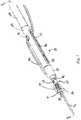
FIG. 1 is an isometric view of a first embodiment for a suture locking device in an unfired position;FIG. 2 is a longitudinal, cross-sectional view of the suture locking device ofFIG. 1 ;FIG. 3 is an exploded, isometric view of the suture locking device ofFIG. 1 ;FIG. 4A is an isolated, isometric view of the inner locking member ofFIG.3 ;FIG. 4B is a cross-sectional view of the inner locking member ofFIG. 4A , taken along line B-B;FIG. 5A is an isolated, isometric view of the outer locking member shown inFIG. 3 ;FIG. 5B is a cross-sectional view of the outer locking member shown inFIG. 5A , taken along line B-B;FIG. 6 is an isometric view of the adaptor and the anchor section of the launching member prior to attachment;FIG. 7A is a cross-sectional view of the suture locking device in an initial loading stage;FIG. 7B is a cross-sectional view of the suture locking device, in which the launching member is being inserted into the adaptor during loading;FIG. 7C is a cross-sectional view of the suture locking device at the end stage of loading, wherein the launching member has been lowered into axial alignment with the adaptor and housing;FIG. 8A is an isometric view of a launching member modified in accordance with an alternative embodiment for attaching the launching member to a drive cable;FIG. 8B is an isometric view showing the launching member ofFIG. 8A attached to the distal end of a ferrule and modified adaptor;FIG. 9 is a plan view of an exemplary deployment handle for the suture locking device;FIG. 10 is a cross-sectional view of the deployment handle ofFIG. 9 ;FIG. 11 is a cross-sectional view of the suture locking device ofFIG. 1 , showing the device threaded with suture material prior to firing;FIG. 12 is a cross-sectional view similar toFIG. 11 , showing the inner and outer locking members engaging during the initial stages of firing;FIG. 13 is a cross-sectional view of the device ofFIG. 11 , showing the components of the knotting element engaged just prior to fracture; andFIG. 14 is a cross-sectional view similar toFIG. 11 , showing the suture material severed and the knotting element detached from the device post firing.- During an endoscopic surgical procedure an endoscope, containing onboard visualization, is passed through a body orifice to reach a surgical site. Using the onboard visualization, small-diameter flexible instruments are manipulated at the site to join tissue segments together. Typically, the tissue segments are joined with a thin, flexible suturing material such as thread, wire or the like. Following the joining procedure, the suture material is secured in place to prevent the tissue from separating. During an open surgical procedure, in which a larger incision is made to accommodate instruments, suture materials are oftentimes joined by tying knots at the loose ends of the material. Various devices have been developed to assist the surgeon in tying knots during surgical procedures, including suture clip-type devices. In endoscopic procedures, however, knot tying can be difficult and time-consuming due to the small available working area within the endoscope. Oftentimes, the resulting knots lack the adequate holding strength or tightness to maintain the tissue junction. Accordingly, it is desirable to provide a suture locking device that can effectively be used in the confined space available in an endoscopic procedure. Additionally, it is desirable to provide a suture locking device that provides for in-line tensioning of the suture material prior to joining the suture ends together. Further, it is desirable to provide a suture locking device that can be reloaded and reused to position multiple suture knotting elements during a procedure.
- Referring now to the drawings in detail, wherein like numerals indicate the same elements throughout the views,
FIGS. 1-3 illustrate a first embodiment for asuturing locking device 20 of the present description which is intended to be coupled to endoscope for insertion within a body. Suture lockingdevice 20 deploys a knotting element during an endoscopic surgical procedure to effectively lock one or more pieces of suture material and prevent the material from dislodging within the patient's body. As shown in the Figures,suture locking device 20 comprises a substantially cylindrical, longitudinal launchingmember 24. The distal portion of launchingmember 24 comprises aninner locking member 26, which is shown in greater detail inFIGS. 4A and 4B . Aflange 31 is preferably located at the distal tip of inner lockingmember 26.Flange 31 includes an opening into an axially-extending bore orchannel 30.Bore 30 is sized to allow asuture material 36 to be inserted therethrough. The opening to bore 30 may be tapered, as indicated byreference numeral 28, to facilitate the threading ofsuture material 36 into the bore. Launchingmember 24 also includes anopening 35 from the proximal end ofbore 30 to the exterior of the launching member, to enablesuture material 36 to exit the member.Opening 35 may be angled, as indicated byreference numeral 38, to guidesuture material 36 in a proximal exit direction along the outer surface ofdevice 20. - The outer circumference of inner locking
member 26 comprises an uneven surface area that engagessuture material 36 when the knotting element is deployed. In the embodiment shown, the uneven surface area comprises a plurality of spaced indentations, as indicated byreference numeral 39.Indentations 39 are spaced apart distal ofsuture opening 35 to engage the proximal portion ofsuture material 36 as the material is looped back distally during firing. In addition to spaced indentations, other types of sculpted surface areas may also be utilized on the outer circumference of inner lockingmember 26 for engagingsuture material 36 during firing. A pair ofpositional stops 41 are located on opposite sides of inner lockingmember 26 adjacent to sutureopening 35. Positional stops 41 are shaped with a rampedproximal side 43 and a squared off distal end 45. The rampedproximal side 43 enables an outer locking member, which will be described below, to pass distally over stops 41 during firing to engageinner locking member 26. Once the outer locking member passes overpositional stops 41 and onto the distal end of inner lockingmember 26, the squared off distal end 45 of the stops blocks the outer locking member from moving proximally and disengaging from the knotting element. - As shown in
FIGS. 2 and3 , the proximal end of launchingmember 24 comprises an anchor section orknot tying element 40.Anchor section 40 comprises a longitudinally-extending, cylindrical shaft with a rounded proximal end.Anchor section 40 connects launchingmember 24 to adrive cable 42 so that the member may be moved by the cable during firing. A semi-circular cutout orrecess 44 is formed in the outer surface ofanchor section 40.Cutout 44 is shaped to engage a mating lip on a drive cable connector, which will be described below, when launchingmember 24 is inserted intodevice 20. - Between the
inner locking member 26 andanchor section 40 of launchingmember 24, is afracture section 32 shown inFIGS. 2 and3 .Fracture section 32 comprises an area of reduced diameter along the longitudinal length of launchingmember 24. Infracture section 32, the diameter of launchingmember 24 is substantially less than the diameter of the remaining length of the member, so as to form a weak point in the member. When pressure is applied to launchingmember 24 during firing, the reduced diameter infracture section 32 causes structural failure at this point, thereby separating the distal end of launchingmember 24, includinginner locking member 26, fromanchor section 40 of the launching member. The particular diameter utilized withinfracture section 32 will vary depending upon the diameter of the distal and proximal portions of launchingmember 24, as well as the strength of the particular materials used in manufacturing the launching member. The longitudinal length offracture section 32 is preferably minimized to the shortest length necessary to ensure fracturing. The distal and proximal portions of launchingmember 24 adjacent to fracturesection 32 have a parabolic shape, as indicated byreference numeral 52 inFIG. 2 , to concentrate the stress on launchingmember 24 within the fracture section. In the embodiment described above, launchingmember 24 is formed as a single unit from a biocompatible plastic material such as, for example, polyetheretherketone (PEEK). In addition to PEEK, other biocompatible materials such as, for example, Vectra, may be used to form the launching member. - A cylindrical
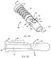
outer locking member 64 is disposed about the outer periphery of launchingmember 24. As shown in greater detail inFIGS. 5A and 5B , the inner surface of outer lockingmember 64 is separated into a firstinner diameter 66 and a second, smallerinner diameter 70. The distal opening to firstinner diameter 66 is tapered, as shown at 72, to provide a lead-in guide forinner locking member 26. The proximal end of firstinner diameter 66 is also angled inwardly towards secondinner diameter 70 to form anend stop 74. A detent 76 is formed on the outer circumference of launchingmember 24, as shown inFIGS. 2 and3 , for retaining outer lockingmember 64 in an unlocked position whilesuture locking device 20 is advanced to the suture site. In an unfired position,end stop 74 rests in contact with detent 76 on launchingmember 24 to position outer lockingmember 64 proximal of inner lockingmember 26 andsuture opening 35. The outer diameter of inner lockingmember 26, includingindentations 39, is greater than secondinner diameter 70 of outer lockingmember 64. This diameter differential between inner andouter locking members inner locking member 26 to contact end stop 74 as launchingmember 24 moves proximally during firing. The contact between inner lockingmember 26 and end stop 74 terminates proximal movement of the inner locking member, and prevents the inner locking member from traveling completely through outer lockingmember 64. - First
inner diameter 66 is selected to provide a clearance between the inner surface of outer lockingmember 64 and the outer surface of inner lockingmember 26 that is sufficient to deformsuture material 36 between the opposing surfaces when the inner and outer locking members are joined into a knotting element. Additionally,indentations 39 along the outer surface of inner lockingmember 26 increase the contact area betweensuture material 36 and the inner locking member. Secondinner diameter 70 extends proximally fromend stop 74 to the proximal end of outer lockingmember 64. In an unlocked position, secondinner diameter 70 surrounds launchingmember 24 proximal of detent 76. The reduced size of secondinner diameter 70 prevents outer lockingmember 64 from moving distally along launchingmember 24 and prematurely locking prior to firing. The outer diameter 78 of outer lockingmember 64 is sized to allow the member and suture material to concurrently pass through a 2.8mm working channel of an endoscope. - As shown in
FIG. 6 ,anchor section 40 of launchingmember 24 is inserted into a cylindrically-shapedadaptor 80. The distal end ofadaptor 80 is open or at least partially cut away, as indicated by reference numeral 79, to accommodateanchor section 40 when launchingmember 24 is loaded into the adaptor. Asemi-circular lip 83 protrudes into the inner diameter ofadaptor 80.Lip 83 engagescutout 44 of launchingmember 24 to operatively connect the launching member andadaptor 80. As shown inFIGS. 2 and3 , a cable connector 81 is disposed in the proximal end ofadaptor 80 for connectingdrive cable 42 to the adaptor and, correspondingly, to launchingmember 24. Drivecable 42 includes a coineddistal end 82 for attachment within cable connector 81. The larger size of coinedend 82 locks the cable within connector 81. Apin 88 is inserted throughadaptor 80 and connector 81 via pairs ofopenings Openings device 20.Pin 88 retains cable connector 81 withinadaptor 80. - A
cylindrical housing 84 extends proximally along the device axis from outer lockingmember 64.Housing 84 includes an open, distal end 86 that surrounds the outer circumference ofadaptor 80. The inner diameter of open distal end 86 is selected to enableadaptor 80 to move freely in an axial direction withinhousing 84. The axial length ofhousing 84 is sufficient to allowadaptor 80 to pull a substantial length of launchingmember 24 into the housing during firing, thereby assuring that the tension applied to drivecable 42 is fully transferred to fracturesection 32. The distal end ofhousing 84 also serves as a proximal end stop 90 for outer lockingmember 64. End stop 90 maintains outer lockingmember 64 in a fixed position during firing, thereby enabling inner lockingmember 26 to travel proximally into the firstinner diameter 66 of the outer locking member. Asinner locking member 26 travels into firstinner diameter 66, outer lockingmember 64 plastically deforms around the inner locking member due to the limited clearance between the outer surface of the inner locking member and the inner surface of the outer locking member. - In an exemplary embodiment, the clearance between the opposing surfaces of the inner and
outer locking members member 64 about the exterior of inner lockingmember 26. The clearance between the inner and outer locking members may vary, however, depending upon the type of suture material being joined. Preferably, the clearance between the opposing locked surfaces is less than the diameter of the suture material, thereby assuring deformation of the material and increased friction between the suture material and mating surfaces of the knotting element. - As shown in
FIGS. 1 and3 ,housing 84 includes a pair oflongitudinal side slots 96 through the outer diameter of the housing. The ends ofpin 88 extend beyondadaptor openings 87 intoside slots 96. Eachside slot 96 aligns with one of the exposed ends ofpin 88 so that the pin ends ride along the slots during firing. The movement ofpin 88 throughslots 96 properly orientsadaptor 80 to preventdrive cable 42 from rotating withinhousing 84 as the cable moves linearly during firing. Spaced aroundhousing 84 fromside slots 96 are a pair ofholes 98 that provide a passageway forsuture material 36 to pass throughhousing 84 for in-line tensioning and cutting, as will be described in more detail below. - To load launching
member 24 intodevice 20,adaptor 80 and cable connector 81 are first advanced distally until the partially open end ofadaptor 80 extends beyond the open distal end ofhousing 84, as shown inFIG. 7A . Launchingmember 24 with outer lockingmember 64 loaded thereon (referred to herein as the knot tying element), is then inserted into the distal end ofadaptor 80, by anglinganchor section 40 of the launching member into adaptor opening 79, as shown inFIG. 7B . Asanchor section 40 is angled intoadaptor 80,cutout 44 of the anchor section moves into position abovelip 83 of the adaptor. Oncecutout 44 is in position overlip 83, launchingmember 24 is lowered down intoadaptor 80 until the launching member is axially aligned withadaptor 80 andhousing 84, as shown inFIG. 7C . Once launchingmember 24 is lowered,lip 83 engagescutout 44 to enableadaptor 80 to pull the launching member proximally when tension is applied to the adaptor throughdrive cable 42. FIGS. 8A and 8B illustrate an alternative embodiment for attachingdrive cable 42 to a launching member. In this embodiment, the launching member and adaptor are both modified to form a reloadable connection therebetween. As shown inFIG. 8A , a modified launchingmember 124 includes a plurality ofbayonets 100.Bayonets 100 extend from apost 102 at the proximal end of launchingmember 124. Drivecable 42 is in turn securely attached, such as by welding or coining, to aferrule 104, having a plurality of circumferential openings 106.Ferrule 104 is attached by apin 110 to the open distal end of a modified housing 184. To attachdrive cable 42 to launchingmember 124,ferrule 104 is threaded over the proximal end of the launching member such that openings 106 pass betweenbayonets 100. To lockferrule 104 to launchingmember 124, the launching member is rotated relative to the ferrule untilbayonets 100 reach openings 106. Asbayonets 100 reach openings 106, the bayonets snap through the openings, locking launchingmember 124 toferrule 104, as shown inFIG. 8B . Asdrive cable 42 is pulled proximally during firing, the interaction betweenbayonets 100 and openings 106 pulls launchingmember 124 and, thus, inner lockingmember 26, proximally into outer lockingmember 64. To release launchingmember 124 fromferrule 104, the launching member and modified housing 184 (with the attached ferrule) are twisted in opposite directions, causingbayonets 100 to disengage from openings 106. Oncebayonets 100 are disengaged,ferrule 104 with attacheddrive cable 42 may be removed from launchingmember 124 and reattached to a new launching member by insertingferrule 104 over the proximal end of the new launching member and twisting the bayonets into openings 106.- Returning now to
FIG. 2 , acatheter 130 such as, for example, a Bowden cable, is attached to the proximal end ofadaptor 84. The inner diameter of the open proximal end ofadaptor 84 may be sized to permit a light interference fit withcatheter 130, to enable the adaptor and remaining aspects ofsuture locking device 20 to be detached from the catheter. Alternatively,suture locking device 20 may be permanently joined tocatheter 130 at the open proximal end ofadaptor 84. FIG. 9 illustrates the proximal end ofcatheter 130 and anexemplary handle 132 for deploying a knotting element fromsuture locking device 20. Handle 132 is attached at the proximal end ofdrive cable 42 for applying tension to the cable. Handle 132 comprises alongitudinal body portion 134, as well as agrip portion 136 for engaging the surgeon's fingers during operation ofdevice 20. Athumb guide 144 is located at the proximal end ofhandle 132. As shown in greater detail inFIG. 10 , the distal end ofhandle 132 includes anouter clamp 150 having a center bore for passage ofcatheter 130. A ring 146 is welded to the proximal end ofcatheter 130 and retained betweenclamp 150 and handlebody 134 to secure the coil. Drivecable 42 extends proximally beyondclamp 150 andcatheter 130 into a center bore 154 ofhandle body 134. A retaining member 156 is longitudinally disposed in bore 154 ofhandle body 134.Grip 136 is attached to retaining member 156 to move the retaining member withinhandle body 134 in response to pressure applied to the grip by the surgeon.- Drive
cable 42 extends into a center bore within retaining member 156. The proximal end ofdrive cable 42 is secured within retaining member 156 by an attachment mechanism, such as, for example, a piece of metal tubing crimped to the end of the cable. Drivecable 42 is locked within retaining member 156 so as to move with the retaining member along the longitudinal axis ofhandle body 134. A resilient member 158 extends aboutdrive cable 42 between the proximal end ofhandle body 134 and retaining member 156. Resilient member 158 serves to bias cable connector 81 into a proximal position withinadaptor 80. Anattachment mechanism 162 is lodged in the proximal end ofhandle body 134 to attachthumb guide 144 to the handle body, and to allow for rotation of the guide relative to the handle body. Tension is applied to drivecable 42 by pulling proximally ongrip 136. Asgrip 136 moves proximally, retaining member 156 moves proximally within bore 154 ofhandle body 134, due to the connection between the grip and retaining member. As retaining member 156 moves proximally, the length ofdrive cable 42 is pulled proximally, increasing the tension on the cable. The increased tension ondrive cable 42 is transferred to launchingmember 24 via the interconnection between cable connector 81,adaptor 80, and launchingmember 24. Handle body bore 154 is sized to allowdrive cable 42 to be pulled a sufficient distance to pullinner locking member 26 into outer lockingmember 64, as well as separate the knotting element from launchingmember 24. - To deploy a knotting element from
suture locking device 20, the device is introduced into the working channel of an externalized endoscope in an initial, unfired position. Suture lockingdevice 20 is advanced through the working channel of the endoscope until inner andouter locking members Suture material 36 that has been externalized out the patient's mouth (or other orifice or incision) is threaded into the distal end of inner lockingmember 26. The suture material is passed throughbore 30 of inner lockingmember 26 and out through opening 35 of launchingmember 24. Upon exiting launchingmember 24, the ends ofsuture material 36 are passed throughholes 98 inhousing 84 and retrieved by the surgeon. The threaded path ofsuture material 36 is shown inFIG. 11 . - Following threading of
suture material 36 intodevice 20, the surgeon reintroduces the endoscope into the patient, and advances the scope to the suture site using the suture strands as a guide. In-line tension is maintained onsuture material 36 whiledevice 20 is passed towards the suture site by holding the externalized ends of the suture material. Oncesuture locking device 20 is in position at the suture site, tension is applied tosuture material 36, as well as to handle 132, to fire the device. Asgrip 136 is drawn proximally, drivecable 42 is pulled proximally throughhandle 132,catheter 130 andhousing 84. The movement ofdrive cable 42 applies tension toadaptor 80, which in turn pulls launchingmember 24 proximally due to the interaction between cut-out 44 andlip 83. As launchingmember 24 moves proximally along the device axis, inner lockingmember 26 is drawn into firstinner diameter 66 of outer lockingmember 64, as shown inFIG. 12 . This interaction between inner andouter locking members material 36 back in a distal direction, and holds the suture material tight, preventing the loss of tension. - As pressure continues to be applied to drive
cable 42 byhandle 132, inner lockingmember 26 is pulled further within outer lockingmember 64, causing the outer locking member to plastically deform about the inner locking member due to the small tolerance between the opposing surfaces of the locking members. Asinner locking member 26 is pulled within outer lockingmember 64,suture material 36, which extends from the proximal end of inner member bore 30, is trapped between the outer diameter of the inner locking member and the firstinner diameter 66 of the outer locking member, as shown inFIG. 13 . Due to the limited clearance between the inner and outer locking member surfaces,suture material 36 is deformed therebetween. The uneven outer surface of inner lockingmember 26 increases the friction betweensuture material 36 and lockingmembers suture material 36 is tensioned between inner andouter locking members flange 31 creates a right angle bend in the material, further increasing the strength of the suture lock within the knotting element. - As outer locking
member 64 plastically deforms about inner lockingmember 26, launchingmember 24 andadaptor 80 move proximally withinhousing 84, with the outer ends ofpin 88 moving throughside slots 96. Asadaptor 80 moves into the proximal end ofhousing 84, the proximal edge of the adaptor contacts the portion ofsuture material 36 extending through the housing between holes 98. The contact between the edge of the advancingadaptor 80 andsuture material 36 severs the suture material withinhousing 84.FIG. 14 shows the distal separated end ofsuture material 36 after the proximal edge ofadaptor 80 has moved proximally beyondholes 98 and completely severed the suture material. - After severing, the distal end of
suture material 36 is locked between inner andouter locking members hole 98 ofhousing 84. As tension continues to be applied to drivecable 42 by way ofhandle 132, inner lockingmember 26 is prevented from further proximal movement within outer lockingmember 64 byend stop 74. Likewise, the locked inner andouter locking members housing 84, and thereby prevented from further proximal movement. Once inner andouter locking members member 24 viadrive cable 42 generates a material failure or break atfracture section 32 of the launching member. The breaking tension offracture section 32 is greater than the force required to plastically deform outer lockingmember 64 over inner lockingmember 26. The difference in tension force assures that inner andouter locking members member 24. As launchingmember 24 breaks apart atfracture section 32, the locked inner andouter members member 24 to form a separate knotting element 170, shown inFIG 14 . In the knotting element 170,flange 31 andpositional stops 41 preventouter locking member 64 from moving relative toinner locking member 26. Accordingly, inner andouter locking members suture material 36 deformed therebetween. - After separating from inner locking
member 26, the remaining portion of launchingmember 24 is propelled proximally untilpin 88 contacts the proximal end ofside slots 96, thereby stopping further proximal movement of the launching member. After firing,adaptor 80 and the remaining portion of launchingmember 24, shown inFIG. 14 , are removed from the body through the endoscope, leaving knotting element 170 at the suture site. After the remaining portions ofdevice 20 have been removed from the body, the device may be reloaded with a new launching member, as described above, and the firing process repeated, to lock additional pieces of suture material. - The invention is defined in the appended claims that follow :
Claims (10)
- A suture locking device (20) comprising:a. an adapter (80, 84) for insertion into a body, said adapter (80, 84) having a proximal end, a distal end (79) and a lip (83) within said distal end (79) projecting towards an interior of said distal end (79), wherein said distal end (79) of said adaptor (80, 84) is at least partially cut away;b. a knot tying element (24) releasably attachable to said distal end (79) of said adapter (80, 84), said knot tying element (24) having a distal and a proximal end (40), said proximal end (40) of said knot tying element (24) having a recess (44) thereon, said proximal end (40) of said knot tying element (24) being insertableby angling said proximal end (40) of said knot tying element (24) within said at least partially cut away distal end (79) of said adapter (80, 84) and then repositioning said knot tying element (24) into said adaptor (80, 84) such that said knot tying element (24) is axially aligned with said adaptor (80, 84) and said lip (83) and said recess (44) mate with each other to form a releasable lock.
- The suture locking device (20) of claim 1 wherein said knot tying element (24) further comprises a locking element (26) having a bore (30) adapted for a suture (36) to run therethrough, said locking element (26) having an outer surface with a plurality of indentations (39) disposed thereon.
- The suture locking device (20) of claim 1 wherein said distal end of said adapter (80, 84) has a first hole (98) on a first side of said adapter and a second hole (98) on a second side of said adapter wherein a suture (36) can go through said two holes (98) and wherein said holes (98) have centers which are at different locations along a longitudinal axis of said adapter (80, 84).
- The suture locking device (20) of claim 1 further comprising a catheter (130) having a distal end attached to said proximal end of said adapter (80, 84).
- The suture locking device (20) of claim 4 further comprising a drive cable (42) extending along and within said catheter (13), said drive cable (42) having a distal end attached to said proximal end of said adapter (80, 84).
- The suture locking device (20) of claim 1 wherein said adapter (80, 84) is coupled to an endoscope.
- The suture locking device (20) of claim 6 wherein said adapter (80, 84) is inserted into the working channel of an endoscope.
- The suture locking device (20) of claim 1 wherein said adapter (80, 84) is substantially cylindrical.
- The suture locking device (20) of claim 8 wherein said adapter (80, 84) has an outer diameter less than 2.8mm.
- The suture locking device (20) of claim 1 wherein said knot tying element (24) further comprises a locking element (26) having a bore (30) with a suture running therethrough, said locking element (26) having an outer surface with a plurality of indentations (29) disposed thereon and wherein said locking element (26) comprises polyetheretherketone.
Applications Claiming Priority (1)
| Application Number | Priority Date | Filing Date | Title |
|---|---|---|---|
| US11/437,440US20070270907A1 (en) | 2006-05-19 | 2006-05-19 | Suture locking device |
Publications (3)
| Publication Number | Publication Date |
|---|---|
| EP1857055A2 EP1857055A2 (en) | 2007-11-21 |
| EP1857055A3 EP1857055A3 (en) | 2010-03-24 |
| EP1857055B1true EP1857055B1 (en) | 2016-04-06 |
Family
ID=38476009
Family Applications (1)
| Application Number | Title | Priority Date | Filing Date |
|---|---|---|---|
| EP07252081.0ANot-in-forceEP1857055B1 (en) | 2006-05-19 | 2007-05-21 | Suture locking device |
Country Status (8)
| Country | Link |
|---|---|
| US (1) | US20070270907A1 (en) |
| EP (1) | EP1857055B1 (en) |
| JP (1) | JP5122181B2 (en) |
| CN (1) | CN101073507B (en) |
| AU (1) | AU2007202244B2 (en) |
| BR (1) | BRPI0704501B8 (en) |
| CA (1) | CA2589571C (en) |
| MX (1) | MX2007006073A (en) |
Families Citing this family (115)
| Publication number | Priority date | Publication date | Assignee | Title |
|---|---|---|---|---|
| US7615076B2 (en) | 1999-10-20 | 2009-11-10 | Anulex Technologies, Inc. | Method and apparatus for the treatment of the intervertebral disc annulus |
| US8128698B2 (en) | 1999-10-20 | 2012-03-06 | Anulex Technologies, Inc. | Method and apparatus for the treatment of the intervertebral disc annulus |
| US7004970B2 (en) | 1999-10-20 | 2006-02-28 | Anulex Technologies, Inc. | Methods and devices for spinal disc annulus reconstruction and repair |
| US8632590B2 (en) | 1999-10-20 | 2014-01-21 | Anulex Technologies, Inc. | Apparatus and methods for the treatment of the intervertebral disc |
| US7655004B2 (en) | 2007-02-15 | 2010-02-02 | Ethicon Endo-Surgery, Inc. | Electroporation ablation apparatus, system, and method |
| US7815662B2 (en) | 2007-03-08 | 2010-10-19 | Ethicon Endo-Surgery, Inc. | Surgical suture anchors and deployment device |
| US8075572B2 (en) | 2007-04-26 | 2011-12-13 | Ethicon Endo-Surgery, Inc. | Surgical suturing apparatus |
| US8100922B2 (en) | 2007-04-27 | 2012-01-24 | Ethicon Endo-Surgery, Inc. | Curved needle suturing tool |
| US20090024144A1 (en) | 2007-07-18 | 2009-01-22 | Zeiner Mark S | Hybrid endoscopic/laparoscopic device for forming serosa to serosa plications in a gastric cavity |
| EP2016909A2 (en) | 2007-07-18 | 2009-01-21 | Ethicon Endo-Surgery, Inc. | Device for insufflating the interior of a gastric cavity of a patient |
| US8579897B2 (en) | 2007-11-21 | 2013-11-12 | Ethicon Endo-Surgery, Inc. | Bipolar forceps |
| US8262655B2 (en) | 2007-11-21 | 2012-09-11 | Ethicon Endo-Surgery, Inc. | Bipolar forceps |
| US8568410B2 (en) | 2007-08-31 | 2013-10-29 | Ethicon Endo-Surgery, Inc. | Electrical ablation surgical instruments |
| US20090112059A1 (en) | 2007-10-31 | 2009-04-30 | Nobis Rudolph H | Apparatus and methods for closing a gastrotomy |
| US8480657B2 (en) | 2007-10-31 | 2013-07-09 | Ethicon Endo-Surgery, Inc. | Detachable distal overtube section and methods for forming a sealable opening in the wall of an organ |
| US8262680B2 (en) | 2008-03-10 | 2012-09-11 | Ethicon Endo-Surgery, Inc. | Anastomotic device |
| US8409252B2 (en)* | 2008-03-25 | 2013-04-02 | Linvatec Corporation | Knotless suture anchor |
| US8162978B2 (en)* | 2008-03-25 | 2012-04-24 | Linvatec Corporation | Non-metallic knotless suture anchor |
| US8652150B2 (en) | 2008-05-30 | 2014-02-18 | Ethicon Endo-Surgery, Inc. | Multifunction surgical device |
| US8679003B2 (en) | 2008-05-30 | 2014-03-25 | Ethicon Endo-Surgery, Inc. | Surgical device and endoscope including same |
| US8771260B2 (en) | 2008-05-30 | 2014-07-08 | Ethicon Endo-Surgery, Inc. | Actuating and articulating surgical device |
| US8070759B2 (en) | 2008-05-30 | 2011-12-06 | Ethicon Endo-Surgery, Inc. | Surgical fastening device |
| US8114072B2 (en) | 2008-05-30 | 2012-02-14 | Ethicon Endo-Surgery, Inc. | Electrical ablation device |
| US8317806B2 (en)* | 2008-05-30 | 2012-11-27 | Ethicon Endo-Surgery, Inc. | Endoscopic suturing tension controlling and indication devices |
| US8906035B2 (en) | 2008-06-04 | 2014-12-09 | Ethicon Endo-Surgery, Inc. | Endoscopic drop off bag |
| US8403926B2 (en) | 2008-06-05 | 2013-03-26 | Ethicon Endo-Surgery, Inc. | Manually articulating devices |
| US8709040B2 (en) | 2008-06-26 | 2014-04-29 | Vitasynergies, Llc | Suture anchor, guide for locating a hole in a bone, and suture anchor delivery tool |
| US8361112B2 (en) | 2008-06-27 | 2013-01-29 | Ethicon Endo-Surgery, Inc. | Surgical suture arrangement |
| US8888792B2 (en) | 2008-07-14 | 2014-11-18 | Ethicon Endo-Surgery, Inc. | Tissue apposition clip application devices and methods |
| US8262563B2 (en) | 2008-07-14 | 2012-09-11 | Ethicon Endo-Surgery, Inc. | Endoscopic translumenal articulatable steerable overtube |
| US8211125B2 (en) | 2008-08-15 | 2012-07-03 | Ethicon Endo-Surgery, Inc. | Sterile appliance delivery device for endoscopic procedures |
| US8529563B2 (en) | 2008-08-25 | 2013-09-10 | Ethicon Endo-Surgery, Inc. | Electrical ablation devices |
| US8241204B2 (en) | 2008-08-29 | 2012-08-14 | Ethicon Endo-Surgery, Inc. | Articulating end cap |
| US8480689B2 (en) | 2008-09-02 | 2013-07-09 | Ethicon Endo-Surgery, Inc. | Suturing device |
| US8409200B2 (en) | 2008-09-03 | 2013-04-02 | Ethicon Endo-Surgery, Inc. | Surgical grasping device |
| US8114119B2 (en) | 2008-09-09 | 2012-02-14 | Ethicon Endo-Surgery, Inc. | Surgical grasping device |
| US8337394B2 (en) | 2008-10-01 | 2012-12-25 | Ethicon Endo-Surgery, Inc. | Overtube with expandable tip |
| US8163022B2 (en) | 2008-10-14 | 2012-04-24 | Anulex Technologies, Inc. | Method and apparatus for the treatment of the intervertebral disc annulus |
| US8157834B2 (en) | 2008-11-25 | 2012-04-17 | Ethicon Endo-Surgery, Inc. | Rotational coupling device for surgical instrument with flexible actuators |
| US8172772B2 (en) | 2008-12-11 | 2012-05-08 | Ethicon Endo-Surgery, Inc. | Specimen retrieval device |
| US8317827B2 (en) | 2009-01-07 | 2012-11-27 | Ethicon Endo-Surgery, Inc. | Suturing devices and methods |
| US8361066B2 (en) | 2009-01-12 | 2013-01-29 | Ethicon Endo-Surgery, Inc. | Electrical ablation devices |
| US8828031B2 (en) | 2009-01-12 | 2014-09-09 | Ethicon Endo-Surgery, Inc. | Apparatus for forming an anastomosis |
| US9226772B2 (en) | 2009-01-30 | 2016-01-05 | Ethicon Endo-Surgery, Inc. | Surgical device |
| US8252057B2 (en) | 2009-01-30 | 2012-08-28 | Ethicon Endo-Surgery, Inc. | Surgical access device |
| US8037591B2 (en) | 2009-02-02 | 2011-10-18 | Ethicon Endo-Surgery, Inc. | Surgical scissors |
| US9179905B2 (en) | 2009-07-17 | 2015-11-10 | Pivot Medical, Inc. | Method and apparatus for re-attaching the labrum to the acetabulum, including the provision and use of a novel suture anchor system |
| US11246585B2 (en) | 2009-07-17 | 2022-02-15 | Stryker Puerto Rico Limited | Method and apparatus for attaching tissue to bone, including the provision and use of a novel knotless suture anchor system |
| US10058319B2 (en) | 2009-07-17 | 2018-08-28 | Pivot Medical, Inc. | Method and apparatus for attaching tissue to bone, including the provision and use of a novel knotless suture anchor system, including a novel locking element |
| US12232718B2 (en) | 2009-07-17 | 2025-02-25 | Stryker Puerto Rico Limited | Method and apparatus for attaching tissue to bone, including the provision and use of a novel knotless suture anchor system |
| US10238379B2 (en) | 2009-07-17 | 2019-03-26 | Pivot Medical, Inc. | Method and apparatus for attaching tissue to bone, including the provision and use of a novel knotless suture anchor system |
| US10426456B2 (en) | 2009-07-17 | 2019-10-01 | Pivot Medical, Inc. | Method and apparatus for re-attaching the labrum to the acetabulum, including the provision and use of a novel suture anchor system |
| US11197663B2 (en) | 2009-07-17 | 2021-12-14 | Stryker Puerto Rico Limited | Method and apparatus for attaching tissue to bone, including the provision and use of a novel knotless suture anchor system |
| US9149268B2 (en) | 2009-07-17 | 2015-10-06 | Pivot Medical, Inc. | Method and apparatus for attaching tissue to bone, including the provision and use of a novel knotless suture anchor system |
| US10136884B2 (en) | 2009-07-17 | 2018-11-27 | Pivot Medical, Inc. | Method and apparatus for attaching tissue to bone, including the provision and use of a novel knotless suture anchor system, including a retractable sheath |
| US20110098704A1 (en) | 2009-10-28 | 2011-04-28 | Ethicon Endo-Surgery, Inc. | Electrical ablation devices |
| US8608652B2 (en) | 2009-11-05 | 2013-12-17 | Ethicon Endo-Surgery, Inc. | Vaginal entry surgical devices, kit, system, and method |
| US8496574B2 (en) | 2009-12-17 | 2013-07-30 | Ethicon Endo-Surgery, Inc. | Selectively positionable camera for surgical guide tube assembly |
| US8353487B2 (en) | 2009-12-17 | 2013-01-15 | Ethicon Endo-Surgery, Inc. | User interface support devices for endoscopic surgical instruments |
| US8506564B2 (en) | 2009-12-18 | 2013-08-13 | Ethicon Endo-Surgery, Inc. | Surgical instrument comprising an electrode |
| US9028483B2 (en) | 2009-12-18 | 2015-05-12 | Ethicon Endo-Surgery, Inc. | Surgical instrument comprising an electrode |
| US8652153B2 (en) | 2010-01-11 | 2014-02-18 | Anulex Technologies, Inc. | Intervertebral disc annulus repair system and bone anchor delivery tool |
| US9005198B2 (en) | 2010-01-29 | 2015-04-14 | Ethicon Endo-Surgery, Inc. | Surgical instrument comprising an electrode |
| US8460340B2 (en) | 2010-08-30 | 2013-06-11 | Depuy Mitek, Llc | Knotless suture anchor |
| US8469998B2 (en) | 2010-08-30 | 2013-06-25 | Depuy Mitek, Llc | Knotless suture anchor |
| US8435264B2 (en) | 2010-08-30 | 2013-05-07 | Depuy Mitek, Llc | Knotless suture anchor and driver |
| US8540735B2 (en) | 2010-12-16 | 2013-09-24 | Apollo Endosurgery, Inc. | Endoscopic suture cinch system |
| US10092291B2 (en) | 2011-01-25 | 2018-10-09 | Ethicon Endo-Surgery, Inc. | Surgical instrument with selectively rigidizable features |
| US9314620B2 (en) | 2011-02-28 | 2016-04-19 | Ethicon Endo-Surgery, Inc. | Electrical ablation devices and methods |
| US9233241B2 (en) | 2011-02-28 | 2016-01-12 | Ethicon Endo-Surgery, Inc. | Electrical ablation devices and methods |
| US9254169B2 (en) | 2011-02-28 | 2016-02-09 | Ethicon Endo-Surgery, Inc. | Electrical ablation devices and methods |
| EP2683304B1 (en)* | 2011-03-10 | 2019-09-25 | Boston Scientific Scimed, Inc. | Flexible suturing instrument |
| US9049987B2 (en) | 2011-03-17 | 2015-06-09 | Ethicon Endo-Surgery, Inc. | Hand held surgical device for manipulating an internal magnet assembly within a patient |
| CN103917183A (en) | 2011-06-29 | 2014-07-09 | 皮沃特医疗公司 | Method and apparatus for re-attaching the labrum to the acetabulum, including the provision and use of a novel suture anchor system |
| US8968336B2 (en) | 2011-12-07 | 2015-03-03 | Edwards Lifesciences Corporation | Self-cinching surgical clips and delivery system |
| US9078652B2 (en) | 2011-12-19 | 2015-07-14 | Edwards Lifesciences Corporation | Side-entry knotless suture anchoring clamps and deployment tools |
| US9078645B2 (en) | 2011-12-19 | 2015-07-14 | Edwards Lifesciences Corporation | Knotless suture anchoring devices and tools for implants |
| US9017347B2 (en) | 2011-12-22 | 2015-04-28 | Edwards Lifesciences Corporation | Suture clip deployment devices |
| US8986199B2 (en) | 2012-02-17 | 2015-03-24 | Ethicon Endo-Surgery, Inc. | Apparatus and methods for cleaning the lens of an endoscope |
| US9427255B2 (en) | 2012-05-14 | 2016-08-30 | Ethicon Endo-Surgery, Inc. | Apparatus for introducing a steerable camera assembly into a patient |
| US9078662B2 (en) | 2012-07-03 | 2015-07-14 | Ethicon Endo-Surgery, Inc. | Endoscopic cap electrode and method for using the same |
| US9498202B2 (en) | 2012-07-10 | 2016-11-22 | Edwards Lifesciences Corporation | Suture securement devices |
| US10016193B2 (en) | 2013-11-18 | 2018-07-10 | Edwards Lifesciences Ag | Multiple-firing crimp device and methods for using and manufacturing same |
| US9545290B2 (en) | 2012-07-30 | 2017-01-17 | Ethicon Endo-Surgery, Inc. | Needle probe guide |
| US9572623B2 (en) | 2012-08-02 | 2017-02-21 | Ethicon Endo-Surgery, Inc. | Reusable electrode and disposable sheath |
| US10314649B2 (en) | 2012-08-02 | 2019-06-11 | Ethicon Endo-Surgery, Inc. | Flexible expandable electrode and method of intraluminal delivery of pulsed power |
| US9277957B2 (en) | 2012-08-15 | 2016-03-08 | Ethicon Endo-Surgery, Inc. | Electrosurgical devices and methods |
| US10179012B2 (en) | 2013-01-28 | 2019-01-15 | Cartiva, Inc. | Systems and methods for orthopedic repair |
| US9737294B2 (en) | 2013-01-28 | 2017-08-22 | Cartiva, Inc. | Method and system for orthopedic repair |
| US10098527B2 (en) | 2013-02-27 | 2018-10-16 | Ethidcon Endo-Surgery, Inc. | System for performing a minimally invasive surgical procedure |
| US10448946B2 (en) | 2013-03-12 | 2019-10-22 | Apollo Endosurgery Us, Inc. | Endoscopic suture cinch |
| WO2014164955A2 (en)* | 2013-03-12 | 2014-10-09 | Apollo Endosurgery, Inc. | Endoscopic suture cinch system with replaceable cinch |
| US10292694B2 (en) | 2013-04-22 | 2019-05-21 | Pivot Medical, Inc. | Method and apparatus for attaching tissue to bone |
| US9936940B2 (en) | 2013-06-07 | 2018-04-10 | Biomet Sports Medicine, Llc | Method and apparatus for coupling soft tissue to bone |
| US9468527B2 (en) | 2013-06-12 | 2016-10-18 | Edwards Lifesciences Corporation | Cardiac implant with integrated suture fasteners |
| WO2015006739A1 (en) | 2013-07-11 | 2015-01-15 | Edwards Lifesciences Corporation | Knotless suture fastener installation system |
| AU2014362199B2 (en) | 2013-12-12 | 2019-07-11 | Stryker Puerto Rico Limited | Method and apparatus for attaching tissue to bone, including the provision and use of a novel knotless suture anchor system |
| KR101574768B1 (en)* | 2014-02-17 | 2015-12-04 | 동국대학교 산학협력단 | Wire locking device for medical procedure |
| WO2015183749A1 (en) | 2014-05-30 | 2015-12-03 | Edwards Lifesciences Corporation | Systems for securing sutures |
| US10085735B2 (en)* | 2014-10-29 | 2018-10-02 | Smith & Nephew, Inc. | Modular tissue repair kit and devices and method related thereto |
| EP3229703B1 (en) | 2014-12-10 | 2024-08-28 | Edwards Lifesciences AG | Multiple-firing securing device |
| WO2016105511A1 (en) | 2014-12-24 | 2016-06-30 | Edwards Lifesciences Corporation | Suture clip deployment devices |
| US10470759B2 (en) | 2015-03-16 | 2019-11-12 | Edwards Lifesciences Corporation | Suture securement devices |
| CN104706391B (en)* | 2015-03-26 | 2017-06-20 | 诺琅医疗科技(上海)有限公司 | A kind of pad locking conduit that can cut suture |
| GB2547915B (en)* | 2016-03-02 | 2018-05-23 | Cook Medical Technologies Llc | Medical Filament delivery apparatus |
| US10939905B2 (en) | 2016-08-26 | 2021-03-09 | Edwards Lifesciences Corporation | Suture clips, deployment devices therefor, and methods of use |
| US10863980B2 (en) | 2016-12-28 | 2020-12-15 | Edwards Lifesciences Corporation | Suture fastener having spaced-apart layers |
| CN110520060B (en) | 2017-04-14 | 2022-08-09 | 奥林巴斯株式会社 | Wire fixing tool |
| JP6840839B2 (en) | 2017-04-14 | 2021-03-10 | オリンパス株式会社 | Thread fixture |
| CA3065223C (en)* | 2017-06-19 | 2024-05-07 | Harpoon Medical, Inc. | Method and apparatus for cardiac procedures |
| CN112294376B (en)* | 2019-08-29 | 2021-12-28 | 杭州德晋医疗科技有限公司 | A long-range suture locking device of staple and intervention formula for locking suture |
| CN112426188B (en)* | 2020-11-20 | 2021-09-17 | 中国人民解放军陆军军医大学第一附属医院 | Medical scissors |
| US12161318B2 (en) | 2020-12-01 | 2024-12-10 | Dunamis Medical Technologies, Llc | Re-tensionable suture anchor system and related methods |
| CN112855681A (en)* | 2021-02-24 | 2021-05-28 | 上海汇禾医疗科技有限公司 | Locking device and method for locking wire by using same |
| CN116236242B (en)* | 2021-12-07 | 2025-07-01 | 苏州微创骨科医疗工具有限公司 | Wire cutters |
Family Cites Families (12)
| Publication number | Priority date | Publication date | Assignee | Title |
|---|---|---|---|---|
| US5584835A (en)* | 1993-10-18 | 1996-12-17 | Greenfield; Jon B. | Soft tissue to bone fixation device and method |
| JP2605606B2 (en)* | 1993-12-06 | 1997-04-30 | 日本電気株式会社 | Train wireless communication system |
| US5545178A (en)* | 1994-04-29 | 1996-08-13 | Kensey Nash Corporation | System for closing a percutaneous puncture formed by a trocar to prevent tissue at the puncture from herniating |
| US6086608A (en)* | 1996-02-22 | 2000-07-11 | Smith & Nephew, Inc. | Suture collet |
| AU716132B2 (en)* | 1996-02-22 | 2000-02-17 | Smith & Nephew, Inc. | Suture collet |
| US5899921A (en)* | 1997-07-25 | 1999-05-04 | Innovasive Devices, Inc. | Connector device and method for surgically joining and securing flexible tissue repair members |
| US5871504A (en)* | 1997-10-21 | 1999-02-16 | Eaton; Katulle Koco | Anchor assembly and method for securing ligaments to bone |
| US6200329B1 (en)* | 1998-08-31 | 2001-03-13 | Smith & Nephew, Inc. | Suture collet |
| US7993368B2 (en)* | 2003-03-13 | 2011-08-09 | C.R. Bard, Inc. | Suture clips, delivery devices and methods |
| US6524328B2 (en)* | 2001-04-12 | 2003-02-25 | Scion International, Inc. | Suture lock, lock applicator and method therefor |
| US7189238B2 (en)* | 2002-09-25 | 2007-03-13 | Linvatec Corporation | Soft tissue anchor |
| US7255675B2 (en)* | 2004-03-23 | 2007-08-14 | Michael Gertner | Devices and methods to treat a patient |
- 2006
- 2006-05-19USUS11/437,440patent/US20070270907A1/ennot_activeAbandoned
- 2007
- 2007-05-18AUAU2007202244Apatent/AU2007202244B2/ennot_activeCeased
- 2007-05-18BRBRPI0704501Apatent/BRPI0704501B8/ennot_activeIP Right Cessation
- 2007-05-18JPJP2007133305Apatent/JP5122181B2/ennot_activeExpired - Fee Related
- 2007-05-21MXMX2007006073Apatent/MX2007006073A/enactiveIP Right Grant
- 2007-05-21CNCN2007101040650Apatent/CN101073507B/ennot_activeExpired - Fee Related
- 2007-05-21EPEP07252081.0Apatent/EP1857055B1/ennot_activeNot-in-force
- 2007-05-22CACA2589571Apatent/CA2589571C/ennot_activeExpired - Fee Related
Also Published As
| Publication number | Publication date |
|---|---|
| CN101073507B (en) | 2011-06-15 |
| JP2007313316A (en) | 2007-12-06 |
| EP1857055A3 (en) | 2010-03-24 |
| BRPI0704501A (en) | 2008-04-22 |
| CA2589571A1 (en) | 2007-11-19 |
| MX2007006073A (en) | 2009-01-09 |
| CN101073507A (en) | 2007-11-21 |
| AU2007202244B2 (en) | 2012-07-26 |
| US20070270907A1 (en) | 2007-11-22 |
| HK1110191A1 (en) | 2008-07-11 |
| BRPI0704501B1 (en) | 2018-11-27 |
| AU2007202244A1 (en) | 2007-12-06 |
| JP5122181B2 (en) | 2013-01-16 |
| EP1857055A2 (en) | 2007-11-21 |
| CA2589571C (en) | 2016-08-16 |
| BRPI0704501B8 (en) | 2021-06-22 |
Similar Documents
| Publication | Publication Date | Title |
|---|---|---|
| EP1857055B1 (en) | Suture locking device | |
| US20070270908A1 (en) | Suture locking method | |
| AU2007202339B2 (en) | Endoscopic gastric restriction methods and devices | |
| EP1749480B1 (en) | Apparatus for endoscopically performing gastric reduction surgery | |
| EP1839592B1 (en) | Surgical suturing apparatus | |
| EP1908420B1 (en) | Anastomotic ring device with locking means | |
| US8252006B2 (en) | Single pass gastric restriction with a corkscrew style wall anchor | |
| EP1759639A1 (en) | Method and apparatus for endoscopically performing gastric reduction surgery in a single step | |
| MX2007003971A (en) | Adjustable vacuum chamber for a surgical suturing apparatus. | |
| MX2007003979A (en) | Method for instrument insertion through a body orifice. | |
| MX2007003972A (en) | Suture with adhesive/sealant delivery mechanism. | |
| MX2007003974A (en) | Surgical suturing apparatus with needle position indicator. | |
| HK1110191B (en) | Suture locking device | |
| WO2008135083A1 (en) | An anastomotic applier and method for performing endolumenal and/or transluminal anastomosis | |
| AU2007352913A1 (en) | An anastomotic applier and method for performing endolumenal and/or transluminal anastomosis | |
| HK1098320B (en) | Apparatus for endoscopically performing gastric reduction surgery in a single step | |
| HK1113299B (en) | Endoscopic gastric restriction device |
Legal Events
| Date | Code | Title | Description |
|---|---|---|---|
| PUAI | Public reference made under article 153(3) epc to a published international application that has entered the european phase | Free format text:ORIGINAL CODE: 0009012 | |
| AK | Designated contracting states | Kind code of ref document:A2 Designated state(s):AT BE BG CH CY CZ DE DK EE ES FI FR GB GR HU IE IS IT LI LT LU LV MC MT NL PL PT RO SE SI SK TR | |
| AX | Request for extension of the european patent | Extension state:AL BA HR MK YU | |
| REG | Reference to a national code | Ref country code:HK Ref legal event code:DE Ref document number:1110191 Country of ref document:HK | |
| PUAL | Search report despatched | Free format text:ORIGINAL CODE: 0009013 | |
| AK | Designated contracting states | Kind code of ref document:A3 Designated state(s):AT BE BG CH CY CZ DE DK EE ES FI FR GB GR HU IE IS IT LI LT LU LV MC MT NL PL PT RO SE SI SK TR | |
| AX | Request for extension of the european patent | Extension state:AL BA HR MK RS | |
| 17P | Request for examination filed | Effective date:20100824 | |
| 17Q | First examination report despatched | Effective date:20100916 | |
| AKX | Designation fees paid | Designated state(s):AT BE BG CH CY CZ DE DK EE ES FI FR GB GR HU IE IS IT LI LT LU LV MC MT NL PL PT RO SE SI SK TR | |
| GRAP | Despatch of communication of intention to grant a patent | Free format text:ORIGINAL CODE: EPIDOSNIGR1 | |
| INTG | Intention to grant announced | Effective date:20151105 | |
| GRAS | Grant fee paid | Free format text:ORIGINAL CODE: EPIDOSNIGR3 | |
| GRAA | (expected) grant | Free format text:ORIGINAL CODE: 0009210 | |
| AK | Designated contracting states | Kind code of ref document:B1 Designated state(s):AT BE BG CH CY CZ DE DK EE ES FI FR GB GR HU IE IS IT LI LT LU LV MC MT NL PL PT RO SE SI SK TR | |
| REG | Reference to a national code | Ref country code:GB Ref legal event code:FG4D | |
| REG | Reference to a national code | Ref country code:FR Ref legal event code:PLFP Year of fee payment:10 | |
| REG | Reference to a national code | Ref country code:AT Ref legal event code:REF Ref document number:786837 Country of ref document:AT Kind code of ref document:T Effective date:20160415 Ref country code:CH Ref legal event code:EP | |
| REG | Reference to a national code | Ref country code:IE Ref legal event code:FG4D | |
| REG | Reference to a national code | Ref country code:DE Ref legal event code:R096 Ref document number:602007045633 Country of ref document:DE | |
| REG | Reference to a national code | Ref country code:LT Ref legal event code:MG4D Ref country code:NL Ref legal event code:MP Effective date:20160406 | |
| REG | Reference to a national code | Ref country code:AT Ref legal event code:MK05 Ref document number:786837 Country of ref document:AT Kind code of ref document:T Effective date:20160406 | |
| PG25 | Lapsed in a contracting state [announced via postgrant information from national office to epo] | Ref country code:BE Free format text:LAPSE BECAUSE OF NON-PAYMENT OF DUE FEES Effective date:20160531 | |
| PG25 | Lapsed in a contracting state [announced via postgrant information from national office to epo] | Ref country code:NL Free format text:LAPSE BECAUSE OF FAILURE TO SUBMIT A TRANSLATION OF THE DESCRIPTION OR TO PAY THE FEE WITHIN THE PRESCRIBED TIME-LIMIT Effective date:20160406 | |
| PG25 | Lapsed in a contracting state [announced via postgrant information from national office to epo] | Ref country code:IS Free format text:LAPSE BECAUSE OF FAILURE TO SUBMIT A TRANSLATION OF THE DESCRIPTION OR TO PAY THE FEE WITHIN THE PRESCRIBED TIME-LIMIT Effective date:20160806 Ref country code:LT Free format text:LAPSE BECAUSE OF FAILURE TO SUBMIT A TRANSLATION OF THE DESCRIPTION OR TO PAY THE FEE WITHIN THE PRESCRIBED TIME-LIMIT Effective date:20160406 Ref country code:FI Free format text:LAPSE BECAUSE OF FAILURE TO SUBMIT A TRANSLATION OF THE DESCRIPTION OR TO PAY THE FEE WITHIN THE PRESCRIBED TIME-LIMIT Effective date:20160406 Ref country code:PL Free format text:LAPSE BECAUSE OF FAILURE TO SUBMIT A TRANSLATION OF THE DESCRIPTION OR TO PAY THE FEE WITHIN THE PRESCRIBED TIME-LIMIT Effective date:20160406 | |
| PG25 | Lapsed in a contracting state [announced via postgrant information from national office to epo] | Ref country code:AT Free format text:LAPSE BECAUSE OF FAILURE TO SUBMIT A TRANSLATION OF THE DESCRIPTION OR TO PAY THE FEE WITHIN THE PRESCRIBED TIME-LIMIT Effective date:20160406 Ref country code:ES Free format text:LAPSE BECAUSE OF FAILURE TO SUBMIT A TRANSLATION OF THE DESCRIPTION OR TO PAY THE FEE WITHIN THE PRESCRIBED TIME-LIMIT Effective date:20160406 Ref country code:GR Free format text:LAPSE BECAUSE OF FAILURE TO SUBMIT A TRANSLATION OF THE DESCRIPTION OR TO PAY THE FEE WITHIN THE PRESCRIBED TIME-LIMIT Effective date:20160707 Ref country code:SE Free format text:LAPSE BECAUSE OF FAILURE TO SUBMIT A TRANSLATION OF THE DESCRIPTION OR TO PAY THE FEE WITHIN THE PRESCRIBED TIME-LIMIT Effective date:20160406 Ref country code:LV Free format text:LAPSE BECAUSE OF FAILURE TO SUBMIT A TRANSLATION OF THE DESCRIPTION OR TO PAY THE FEE WITHIN THE PRESCRIBED TIME-LIMIT Effective date:20160406 Ref country code:PT Free format text:LAPSE BECAUSE OF FAILURE TO SUBMIT A TRANSLATION OF THE DESCRIPTION OR TO PAY THE FEE WITHIN THE PRESCRIBED TIME-LIMIT Effective date:20160808 | |
| PG25 | Lapsed in a contracting state [announced via postgrant information from national office to epo] | Ref country code:BE Free format text:LAPSE BECAUSE OF FAILURE TO SUBMIT A TRANSLATION OF THE DESCRIPTION OR TO PAY THE FEE WITHIN THE PRESCRIBED TIME-LIMIT Effective date:20160406 | |
| REG | Reference to a national code | Ref country code:CH Ref legal event code:PL | |
| REG | Reference to a national code | Ref country code:DE Ref legal event code:R097 Ref document number:602007045633 Country of ref document:DE | |
| PG25 | Lapsed in a contracting state [announced via postgrant information from national office to epo] | Ref country code:DK Free format text:LAPSE BECAUSE OF FAILURE TO SUBMIT A TRANSLATION OF THE DESCRIPTION OR TO PAY THE FEE WITHIN THE PRESCRIBED TIME-LIMIT Effective date:20160406 Ref country code:LI Free format text:LAPSE BECAUSE OF NON-PAYMENT OF DUE FEES Effective date:20160531 Ref country code:RO Free format text:LAPSE BECAUSE OF FAILURE TO SUBMIT A TRANSLATION OF THE DESCRIPTION OR TO PAY THE FEE WITHIN THE PRESCRIBED TIME-LIMIT Effective date:20160406 Ref country code:CZ Free format text:LAPSE BECAUSE OF FAILURE TO SUBMIT A TRANSLATION OF THE DESCRIPTION OR TO PAY THE FEE WITHIN THE PRESCRIBED TIME-LIMIT Effective date:20160406 Ref country code:MC Free format text:LAPSE BECAUSE OF FAILURE TO SUBMIT A TRANSLATION OF THE DESCRIPTION OR TO PAY THE FEE WITHIN THE PRESCRIBED TIME-LIMIT Effective date:20160406 Ref country code:CH Free format text:LAPSE BECAUSE OF NON-PAYMENT OF DUE FEES Effective date:20160531 Ref country code:EE Free format text:LAPSE BECAUSE OF FAILURE TO SUBMIT A TRANSLATION OF THE DESCRIPTION OR TO PAY THE FEE WITHIN THE PRESCRIBED TIME-LIMIT Effective date:20160406 Ref country code:SK Free format text:LAPSE BECAUSE OF FAILURE TO SUBMIT A TRANSLATION OF THE DESCRIPTION OR TO PAY THE FEE WITHIN THE PRESCRIBED TIME-LIMIT Effective date:20160406 | |
| PLBE | No opposition filed within time limit | Free format text:ORIGINAL CODE: 0009261 | |
| STAA | Information on the status of an ep patent application or granted ep patent | Free format text:STATUS: NO OPPOSITION FILED WITHIN TIME LIMIT | |
| REG | Reference to a national code | Ref country code:IE Ref legal event code:MM4A | |
| 26N | No opposition filed | Effective date:20170110 | |
| REG | Reference to a national code | Ref country code:FR Ref legal event code:PLFP Year of fee payment:11 | |
| REG | Reference to a national code | Ref country code:HK Ref legal event code:GR Ref document number:1110191 Country of ref document:HK | |
| PG25 | Lapsed in a contracting state [announced via postgrant information from national office to epo] | Ref country code:IE Free format text:LAPSE BECAUSE OF NON-PAYMENT OF DUE FEES Effective date:20160521 Ref country code:SI Free format text:LAPSE BECAUSE OF FAILURE TO SUBMIT A TRANSLATION OF THE DESCRIPTION OR TO PAY THE FEE WITHIN THE PRESCRIBED TIME-LIMIT Effective date:20160406 | |
| REG | Reference to a national code | Ref country code:FR Ref legal event code:PLFP Year of fee payment:12 | |
| PG25 | Lapsed in a contracting state [announced via postgrant information from national office to epo] | Ref country code:CY Free format text:LAPSE BECAUSE OF FAILURE TO SUBMIT A TRANSLATION OF THE DESCRIPTION OR TO PAY THE FEE WITHIN THE PRESCRIBED TIME-LIMIT Effective date:20160406 Ref country code:HU Free format text:LAPSE BECAUSE OF FAILURE TO SUBMIT A TRANSLATION OF THE DESCRIPTION OR TO PAY THE FEE WITHIN THE PRESCRIBED TIME-LIMIT; INVALID AB INITIO Effective date:20070521 | |
| PG25 | Lapsed in a contracting state [announced via postgrant information from national office to epo] | Ref country code:TR Free format text:LAPSE BECAUSE OF FAILURE TO SUBMIT A TRANSLATION OF THE DESCRIPTION OR TO PAY THE FEE WITHIN THE PRESCRIBED TIME-LIMIT Effective date:20160406 Ref country code:LU Free format text:LAPSE BECAUSE OF NON-PAYMENT OF DUE FEES Effective date:20160521 Ref country code:MT Free format text:LAPSE BECAUSE OF NON-PAYMENT OF DUE FEES Effective date:20160531 | |
| PG25 | Lapsed in a contracting state [announced via postgrant information from national office to epo] | Ref country code:BG Free format text:LAPSE BECAUSE OF FAILURE TO SUBMIT A TRANSLATION OF THE DESCRIPTION OR TO PAY THE FEE WITHIN THE PRESCRIBED TIME-LIMIT Effective date:20160406 | |
| REG | Reference to a national code | Ref country code:FR Ref legal event code:PLFP Year of fee payment:17 | |
| PGFP | Annual fee paid to national office [announced via postgrant information from national office to epo] | Ref country code:GB Payment date:20230330 Year of fee payment:17 | |
| PGFP | Annual fee paid to national office [announced via postgrant information from national office to epo] | Ref country code:IT Payment date:20230412 Year of fee payment:17 Ref country code:FR Payment date:20230411 Year of fee payment:17 Ref country code:DE Payment date:20230331 Year of fee payment:17 | |
| REG | Reference to a national code | Ref country code:DE Ref legal event code:R119 Ref document number:602007045633 Country of ref document:DE | |
| GBPC | Gb: european patent ceased through non-payment of renewal fee | Effective date:20240521 | |
| PG25 | Lapsed in a contracting state [announced via postgrant information from national office to epo] | Ref country code:DE Free format text:LAPSE BECAUSE OF NON-PAYMENT OF DUE FEES Effective date:20241203 | |
| PG25 | Lapsed in a contracting state [announced via postgrant information from national office to epo] | Ref country code:FR Free format text:LAPSE BECAUSE OF NON-PAYMENT OF DUE FEES Effective date:20240531 | |
| PG25 | Lapsed in a contracting state [announced via postgrant information from national office to epo] | Ref country code:IT Free format text:LAPSE BECAUSE OF NON-PAYMENT OF DUE FEES Effective date:20240521 Ref country code:GB Free format text:LAPSE BECAUSE OF NON-PAYMENT OF DUE FEES Effective date:20240521 |