EP1857032B1 - Vacuum cleaner having primary and secondary cyclone units - Google Patents
Vacuum cleaner having primary and secondary cyclone unitsDownload PDFInfo
- Publication number
- EP1857032B1 EP1857032B1EP20060125823EP06125823AEP1857032B1EP 1857032 B1EP1857032 B1EP 1857032B1EP 20060125823EP20060125823EP 20060125823EP 06125823 AEP06125823 AEP 06125823AEP 1857032 B1EP1857032 B1EP 1857032B1
- Authority
- EP
- European Patent Office
- Prior art keywords
- dust
- unit
- dust collection
- main body
- cyclone unit
- Prior art date
- Legal status (The legal status is an assumption and is not a legal conclusion. Google has not performed a legal analysis and makes no representation as to the accuracy of the status listed.)
- Not-in-force
Links
Images


Classifications
- A—HUMAN NECESSITIES
- A47—FURNITURE; DOMESTIC ARTICLES OR APPLIANCES; COFFEE MILLS; SPICE MILLS; SUCTION CLEANERS IN GENERAL
- A47L—DOMESTIC WASHING OR CLEANING; SUCTION CLEANERS IN GENERAL
- A47L9/00—Details or accessories of suction cleaners, e.g. mechanical means for controlling the suction or for effecting pulsating action; Storing devices specially adapted to suction cleaners or parts thereof; Carrying-vehicles specially adapted for suction cleaners
- A47L9/10—Filters; Dust separators; Dust removal; Automatic exchange of filters
- A47L9/16—Arrangement or disposition of cyclones or other devices with centrifugal action
- A47L9/1616—Multiple arrangement thereof
- A47L9/1625—Multiple arrangement thereof for series flow
- A—HUMAN NECESSITIES
- A47—FURNITURE; DOMESTIC ARTICLES OR APPLIANCES; COFFEE MILLS; SPICE MILLS; SUCTION CLEANERS IN GENERAL
- A47L—DOMESTIC WASHING OR CLEANING; SUCTION CLEANERS IN GENERAL
- A47L5/00—Structural features of suction cleaners
- A47L5/12—Structural features of suction cleaners with power-driven air-pumps or air-compressors, e.g. driven by motor vehicle engine vacuum
- A47L5/22—Structural features of suction cleaners with power-driven air-pumps or air-compressors, e.g. driven by motor vehicle engine vacuum with rotary fans
- A47L5/36—Suction cleaners with hose between nozzle and casing; Suction cleaners for fixing on staircases; Suction cleaners for carrying on the back
- A47L5/362—Suction cleaners with hose between nozzle and casing; Suction cleaners for fixing on staircases; Suction cleaners for carrying on the back of the horizontal type, e.g. canister or sledge type
- A—HUMAN NECESSITIES
- A47—FURNITURE; DOMESTIC ARTICLES OR APPLIANCES; COFFEE MILLS; SPICE MILLS; SUCTION CLEANERS IN GENERAL
- A47L—DOMESTIC WASHING OR CLEANING; SUCTION CLEANERS IN GENERAL
- A47L9/00—Details or accessories of suction cleaners, e.g. mechanical means for controlling the suction or for effecting pulsating action; Storing devices specially adapted to suction cleaners or parts thereof; Carrying-vehicles specially adapted for suction cleaners
- A47L9/10—Filters; Dust separators; Dust removal; Automatic exchange of filters
- A47L9/16—Arrangement or disposition of cyclones or other devices with centrifugal action
- A47L9/1616—Multiple arrangement thereof
- A47L9/1641—Multiple arrangement thereof for parallel flow
Definitions
- the present inventionrelates to a vacuum cleaner, and more particularly, to a vacuum cleaner that can maximize the dust collection volume and easily discharge the collected dusts.
- a vacuum cleaneris a device that can suck air containing dusts using suction generated by a motor mounted in a main body and filter off the dusts in a dust filtering unit.
- the vacuum cleaneris classified into a canister type and an upright type.
- the canister type vacuum cleanerincludes a main body and an suction nozzle connected to the main body by a connection pipe.
- the canister type vacuum cleanerincludes a main body and a suction nozzle integrally formed with the main body.
- a dust collection unit mounted in a cyclone type vacuum cleanerseparates dusts from air using a cyclone principle and the air whose dusts are removed is discharged out of the main body.
- the multi-cyclone dust collection unitincludes a dust collection body defining an outer appearance, a primary cyclone unit for separating relatively large-sized dusts contained in the air, and a secondary cyclone unit to separate relatively small-sized dusts contained in the air.
- the dusts separated by the primary and secondary cyclone unitsare reserved in respective first and second dust reserving units formed in the dust collection body.
- the conventional dust collection unitincludes both of the primary and secondary cyclone units.
- the dust collection unitis detachably mounted in the main body to discharge the collected dusts.
- the conventional dust collection unitincludes both of the primary and secondary cyclone units, a space for the main chamber is structurally reduced. Therefore, the dust collection volume of the main chamber is reduced and thus the user must more frequently empty the dust collection unit.
- the conventional dust collection unitincludes both of the primary and secondary cyclone units, the weight of the dust collection unit increases and thus it difficult for the user to handle the vacuum cleaner when mounting the dust collection unit or discharging the collected dusts.
- the interior roommay be contaminated again during the process for separating the dust collection unit from the main body empty the dust collection unit or dumping the dusts out of the dust collection unit.
- the interior roommay be contaminated again during the process for separating the dust collection unit from the main body empty the dust collection unit or dumping the dusts out of the dust collection unit.
- GB 2404887Adiscloses three different types of vacuum cleaners in which different arrangements of cyclone units for separating dust from air are provided.
- two single cyclonesare arranged in series, one of which is located inside the other within a dust collecting unit.
- a single upstream cycloneis followed by a plurality of downstream cyclone arranged in parallel, wherein all cyclones appear to be attached to the dust collecting unit.
- the present inventionis directed to a vacuum cleaner that substantially obviates one or more problems due to limitations and disadvantages of the related art.
- An object of the present inventionis to provide a vacuum cleaner that is structurally simple while maximizing the dust collection volume.
- Another aspect of the present inventionis to provide a vacuum cleaner that can easily discharge the collected dusts.
- the above-described vacuum cleanerhas the following advantages.
- the primary cyclone unitis provided on the dust collection unit while the secondary cyclone unit is separated from the dust collection unit and provided on the main body unit, the structure of the dust collection unit is simplified and light-weighted. Therefore, the user can more conveniently handle the dust collection unit.
- the size of the first dust collection unitincreases to maximize the dust collection volume.
- the dust collection unitis separated from the main body in a state where it is enclosed, the recontamination if the indoor room by discharging the dusts by opening a cover member at a location where the user wants to discharge the dusts.
- the cover member provided on an upper portion of the dust collection unitis designed to simultaneously open and close the first and second dust collection units, the collected dusts can be effectively discharged.
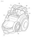
- Fig. 1is a perspective view of a vacuum cleaner according to an embodiment of the present invention
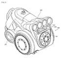
- Fig. 2is a perspective view of the vacuum cleaner Fig. 1 , when a dust collection unit is separated from the vacuum cleaner
- Fig. 3is a perspective view of a dust collection unit according to an embodiment of the present invention.
- a vacuum cleaner 10includes a main body 100 and a dust separation device for separating the dusts contained in the air sucked into the main body 100.
- the vacuum cleaner 10further includes a suction nozzle for sucking the air containing the dusts and a connection pipe for connecting the suction nozzle to the main body 100.
- a main body sucking portion 110is formed on a frontlower end portion of the main body 100 to allow the air to be sucked from the suction nozzle (not shown) into the main body 100.
- a main body discharge unit 120is formed on a side surface of the main body 100 to discharge the air separated from the dusts.
- a main body handle 140is formed on an upper portion of the main body 100.
- a guide cover 160is coupled to a rear portion of the main body 100 to guide the air whose dusts are removed by the dust separation device to the main body 100.
- the dust separation deviceincludes a dust collection unit 200 for primarily separating the dusts contained in the air and a secondary cyclone unit provided on the main body 100 for secondarily separating the dusts from the air whose dusts is primarily separated by the dust collection unit 200.
- the dust collection unit 200is detachably mounted on a front portion of the main body 100. As described above, in order to detachably mount the dust collection unit 200 on the main body 100, a mounting/dismounting lever 142 is provided on the handle 140 of the main body 100 and a hooking end 256 interlocked with the mounting/dismounting lever 142 is formed on the dust collection unit 200.
- the dust collection unit 200includes a primary cyclone unit for generating the cyclone current and a dust collection body 210 having a dust reserving portion in which the dusts separated by the primary cyclone unit.
- the dust collection unit 200is detachably mounted on the main body 100 and communicates with the secondary cyclone unit 300 and the main body 100 as the dust collection unit 200 is mounted on the main body 100.
- the main body 100is provided with an air discharge hole 130 for discharging the air sucked into the main body 100 to the dust collection unit 200.
- the dust collection unit 200is provided with a first sucking hole 212 through which the air is sucked from the air discharge hole 130.
- the first sucking hole 212is formed in a tangent direction of the dust collection unit 200 so as to generate the cyclone current in the dust collection unit 200.
- the dust collection unit 200is provided with a first discharge hole 252 through which the air whose dusts are separated at the primary cyclone unit is discharged.
- the main body 100is provided with a connection passage 114 for guiding the air discharged through the first discharge hole 252 to the secondary cyclone unit 300.
- the secondary cyclone unit 300includes a plurality of small cyclones that are cone-shaped.
- the small cyclonesare connected in parallel.
- the secondary cyclone unit 300is horizontally arranged on a rear-upper portion of the main body 100. That is, the secondary cyclone unit 300 is arranged at a predetermined angle with respect to the main body 100.
- the secondary cyclone unit 300is horizontally arranged on the main body 100, the space efficiency of the vacuum cleaner considering the arrangement of the vacuum motor.
- the secondary cyclone unit 300is separated from the dust collection unit 200 and provided on the main body 100, the structure of the dust collection unit 200 is simplified and light-weighted. Therefore, the user can easily handle the dust collection unit 200.
- the dusts separated by the secondary cyclone unit 300are reserved in the dust collection unit 200.
- the dust collection body 210is provided with a dust sucking hole 254 through which the dusts separated by the second cyclone unit 300 is sucked and a dust reserving portion in which the dusts separated by the secondary cyclone unit 300 are reserved.
- the dust reserving portion formed in the dust collection body 210includes a first dust reserving portion for reserving the dusts separated by the primary cyclone unit and a second dust reserving portion for reserving the dusts separated by the secondary cyclone unit 300.
- the secondary cyclone unit 300is separated from the dust collection unit 200 and provided to the main body 100, the dusts separated at the secondary cyclone unit 300 are reserved in the dust collection unit 200.
- the secondary cyclone unit 300may be inclined downward toward the dust collection unit 200 so that the separated dusts can be effectively directed to the dust collection unit 200.
- the dustsare primarily separated at the first cyclone unit.
- the separated dustsare reserved in the dust collection body 210.
- the air whose dusts are separatedis discharged from the dust collection unit 200 and introduced into the main body 100. Then, the air is directed to the secondary cyclone unit 300 by the connection passage 114 provided on the main body 100.
- the dusts contained in the air introduced into the secondary cyclone unit 300are further separated and the separated dusts are introduced and reserved in the dust collection unit 200. Then, the air is finally discharged to an external side through the main body discharge portion 120 along a passage formed in the main body 100.
- Fig. 4is a sectional view taken along line I-I' of Fig. 3 and Fig. 5 is a sectional view taken along line II-II' of Fig. 3 .
- the dust collection unit 200includes a dust collection body 210 defining an outer appearance, a primary cyclone unit 230 selectively received in the dust collection body 210 and separating the dusts contained in the air, and a cover member 250 for selectively opening and closing an upper portion of the dust collection body 210.
- the dust collection body 210is formed in a cylindricalshape and defines a dust reserving portion for reserving the separated dusts.
- the dust reserving portionincludes a first dust reserving portion 214 for reserving the dusts separated at the primary cyclone unit 230 and a second dust reserving portion 216 for reserving the dusts separated at the secondary cyclone unit 300.
- the dust collection body 210includes a first wall 211 forming the first dust reserving portion 214 and a second wall 212 for forming the second dust reserving portion 216. That is, the second wall 212 is designed to enclose a portion of the second wall 211.
- the second dust reserving portion 216is formed at an outer side of the first dust reserving portion 214.
- the size of the first dust reserving portion 214can be maximized to increase the dust collection volume of the first dust reserving portion 214.
- the first wall 211is provided with a circumferential step 219 for supporting a lower end of the first cyclone unit 230 received therein. Therefore, with reference to the circumferential step 219, the upper portion of the first dust reserving portion 214 has a diameter greater than that of the lower portion.
- a pair of pressing plates 221 and 222are provided on the dust collection body 210 to reduce the volume of the dusts reserved in the first dust reserving unit 214 and thus increase the dust collection amount.
- the pair of pressing plates 221 and 222acts to each other to compress the dusts to reduce the volume of the dusts. Therefore, the density of the dusts reserved in the first dust reserving unit 214 increases, the maximum dust collection amount of the first dust reserving unit 214 increases.
- the pressing plate 222may be a stationery plate fixed on a fixing shaft 224 formed on a bottom of the dust collection body 210.
- the pressing plate 221may be a rotational plate fixed on a rotational shaft coupled to the fixing shaft 224.
- a driven gear 228is coupled to the rotational shaft 226 to rotate by a driving source.
- the main body 100is provided with a driving gear engaged with the driven gear 228 and a driving motor for driving the driving gear.
- the rotational plate 221may rotate in both directions so as to compress the dusts at both sides of the fixing plate 222.
- the driving motormay be a synchronous motor.
- one of the pressing plates 221 and 222is provided to be movable in the dust collection body 210, the present invention is not limited to this embodiment.
- both of the pressing plates 221 and 222may be provided to be movable in the dust collection body 210.
- the dust collection body 210is opened at the upper portion so that the user can discharge the dusts by turning the same over.
- the cover member 250is detachably coupled to the upper portion of the dust collection body 210.
- the primary cyclone unit 230In order to discharge the dusts out of the dust collection body 210, the primary cyclone unit 230 is separated together with the cover member 250. Therefore, the primary cyclone unit 230 is coupled to a lower portion of the cover member 250.
- the primary cyclone unit 230is coupled to the cover member 250, the present invention is not limited to this embodiment.
- the primary cyclone unit 230may be integrally formed with the cover member 250.
- a dust guide passage 232is formed in the primary cyclone unit 230 to effectively discharge the dusts to the primary dust reserving unit 214.
- the dust guide passage 232allows the air to be sucked in the tangent direction and directed downward.
- an inlet 233 of the dust guide passage 232is formed on a side surface of the primary cyclone unit 230 and an outlet 234 of the dust guide passage 232 is formed on a bottom of the primary cyclone unit 230.
- the cover member 250is detachably coupled to the upper portion of the dust collection body 210. That is, the cover member 250 opens and closes simultaneously the first and second dust reserving portions 214 and 216.
- the userin order to empty the dust collection body 210, the user carries the dust collection body 210 to a trash basket or to an outdoor and empties the dust collection body 210 to prevent the indoor side from being recontaminated.
- cover member 250is provided at a bottom with an air discharge hole 251 through which the air whose dusts are separated at the primary cyclone unit 230 is discharged.
- An upper portion of a filter member 260 provided with a plurality of pores 262is coupled to an outer circumference of the air discharge hole 251.
- the air whose dusts are primarily separated at the primary cyclone unit 230is discharged through the air discharge hole 251 via the filter member 260.
- a passage 253 for guiding the air to the first discharge hole 252is formed in the cover member 250. That is, the passage 253 functions as a passage for connecting the discharge hole 251 to the first discharge hole 252.
- the cover member 250is provided with a dust sucking portion 254 through which the dusts separated at the secondary cyclone unit 300 is introduced and a dust discharge hole 257 through which the air introduced into the cover member 250 is discharged to the second dust reserving portion 216.
- the dust sucking hole 254is formed on a top of the cover member 250. As shown in Fig. 3 , the dust sucking hole 254 is provided by two that are symmetrically disposed at both sides of the first discharge hole 252. The dust discharge hole 257 is formed on a bottom of the cover member 250.
- the dust sucking hole 254is formed on the top of the cover member 250 and the dust discharge hole 257 is formed on the bottom of the cover member 250, a space is defined between the dust sucking hole 254 and the dust discharge hole 257.
- the dusts sucked through the dust sucking hole 254is preferably designed to allow the dust to be effective moved to the dust discharge hole 257.
- a guide rib 258is provided to allow the dusts sucked through the dust sucking hole 254 to be effectively moved to the second dust reserving portion 216 through the dust discharge hole 257.
- the dust guide rib 258extends from the dust sucking hole 254 to the dust discharge hole 257. Therefore, the dust guide rib 258 has a first side corresponding to the dust sucking hole 254 and a second side corresponding to the dust discharge hole 257.
- the dusts introduced through the dust sucking hole 254can be effectively directed to the dust discharge hole 257, thereby preventing the dusts introduced into the dust sucking hole 254 from accumulating in the cover member 250.
- the primary cyclone unit 230is provided in the dust collection unit 200 and the secondary cyclone unit 300 is provided in the main body 100.
- the cyclone unitmay further include a third cyclone unit.
- the third cyclone unitis also provided in the main body 100.
- the primarily and secondary cyclones unitsmay be provided in the dust collection unit 200 while the third cyclone unit is provided in the main body 100.
- one or more cyclone unitsare provided in the dust collection unit 200 and the rest are provided in the main body.
- the cyclone unit provided in the dust collection unit 200may be called a dust collection cyclone and the cyclone provided in the main body 100 may be called a main body cyclone.
- One or more dust collection cyclones and one or more main body cyclonemay be provided.
- Fig. 6is a sectional view of the vacuum cleaner.
- the secondary cyclone unit 300is provided on the upper portion of the main body 100.
- a connection passage 114is provided on the lower portion of the secondary cyclone unit 300 to guide the air discharge from the dust collection unit 200 to the secondary cyclone unit 300.
- a second sucking hole 302is formed on the secondary cyclone unit 300 to allow air passed through the connection passage 144 to be sucked into the secondary cyclone unit 300.
- a guide rib 304is formed near the second sucking hole 302 in the tangent direction of the secondary cyclone unit 300.
- the main body 100is provided with an air sucking hole (118 of Fig. 7 ) through which the air whose dusts are removed at the secondary cyclone unit 300 is formed.
- the air sucking hole 118 and the secondary cyclone unit 300communicate with each other when the guide cover 160 is mounted in the secondary cyclone unit 300 and main body 100.
- the guide cover 160shields the secondary cyclone unit 300 and, at the same time, forms a discharge passage (116 of Fig. 7 ) through which the air discharged from the secondary cyclone unit 300 is introduced into the air sucking hole 118.
- Fig. 7is a sectional view of the vacuum cleaner.
- the air sucked through the suction nozzleis directed into the main body 100 through the main body sucking portion 110 and then directed to the dust collection unit 200 through the communication passage 112.
- the air containing the dustsis sucked in the tangent direction of the primary cyclone unit 230 through the first sucking hole 212 of the dust collection body 210. Then, the sucked air rotates downward along the inner circumference of the primary cyclone unit 230, in the course of which the air and dusts are separated by the centrifugal force.
- the air whose dusts are separatedpasses through the filter member 260, in which course of which the dusts of the air are further filtered off. Then, the air is discharged out of the dust collection unit 200 through the first discharge hole 252 and the discharge hole 251.
- the separated dustsare introduced into the dust guide passage 232 in the tangent direction while rotating along the inner circumference of the primary cyclone unit 230.
- the dusts introduced into the dust guide passage 232changes its flow direction in the dust guide passage 232 and move downward through the discharge hole 234 along an outer circumference of the primary cyclone unit 230 to be reserved in the first dust reserving unit 214.
- the air discharged through the first discharge hole 252is introduced into the main body 100. Then, the air is introduced into the secondary cyclone unit 300 via the connection passage 114.
- the airis guided to the inner wall of the secondary cyclone unit 300 in the tangent direction of the through the second sucking hole 310 formed on an end of the connection passage 114 and thus the dusts contained in the air are further separated.
- the airis introduced into the discharge passage 118 formed in the main body 100 and discharged from the main body 100 via the motor pre-filter 152, vacuum motor 150 and main body discharge portion 120.
- the separated dustsare introduced into the dust collection unit 200 through the dust sucking hole 254 and reserved in the second dust reserving unit 216.
- the userseparates the dust collection unit 200 from the main body 100.
- the userseparates the cover member 250 to which the primary cyclone unit 230 is coupled is separated from the dust collection unit 200.
- the dust collection body 210is turned over to discharge the dusts.
- a first dust reserving portion 414a primary cyclone unit 430 selectively received in the dust collection body 210 and separating the dusts contained in the air, and a cover member 450 for selectively opening and closing an upper portion of the dust collection body 410.
- a secondary cyclone unit 300 for further separating the dusts from the air passed through the primary cyclone unit 430 and a dust collection container forming a second dust reserving portion 510 for reserving the dusts separated at the secondary cyclone unit 300 are reservedare provided in the main body 100.
- the dusts separated by the primary and secondary cyclone units 430 and 300are reserved in a separated part.
- the primary cyclone unit 430separates the relatively large-sized dusts while the secondary cyclone unit 300 separates the fine dusts, most of the dusts are stored in the first dust reserving unit 414. That is, the first dust reserving unit 414 is more quickly filled with the dusts. Therefore, the first dust reserving unit 414 must be more frequently empted.
- the dust collection body 410 having the first dust reserving portion 414is separated from the dust collection container 500 having the second dust reserving portion 510.
- the dust collection body 410can be separated from the main body 100 to discharge the dusts reserved in the first dust reserving portion 414.
- the structure of the dust collection body 410is simplified and light-weighted. Therefore, the user can easily handle the dust collection body 410.
- the dust collection container 500is provided to be detachably mounted on the main body 100 so that it can be empted easily after being separated from the main body 100.
- the dust collection container 500is coupled to the main body 100 and then the dust collection unit 400 is coupled to the main body. Therefore, one surface of the dust collection container may be formed to correspond to the shape of the dust collection body 410.
Landscapes
- Engineering & Computer Science (AREA)
- Mechanical Engineering (AREA)
- Filters For Electric Vacuum Cleaners (AREA)
- Electric Suction Cleaners (AREA)
Description
- The present invention relates to a vacuum cleaner, and more particularly, to a vacuum cleaner that can maximize the dust collection volume and easily discharge the collected dusts.
- Generally, a vacuum cleaner is a device that can suck air containing dusts using suction generated by a motor mounted in a main body and filter off the dusts in a dust filtering unit.
- The vacuum cleaner is classified into a canister type and an upright type. The canister type vacuum cleaner includes a main body and an suction nozzle connected to the main body by a connection pipe. The canister type vacuum cleaner includes a main body and a suction nozzle integrally formed with the main body.
- Meanwhile, a dust collection unit mounted in a cyclone type vacuum cleaner separates dusts from air using a cyclone principle and the air whose dusts are removed is discharged out of the main body.
- In recent years, in order to improve the dust collection performance, a multi-cyclone dust collection unit having a plurality of cyclone units has been proposed.
- That is, the multi-cyclone dust collection unit includes a dust collection body defining an outer appearance, a primary cyclone unit for separating relatively large-sized dusts contained in the air, and a secondary cyclone unit to separate relatively small-sized dusts contained in the air.
- The dusts separated by the primary and secondary cyclone units are reserved in respective first and second dust reserving units formed in the dust collection body.
- The conventional dust collection unit includes both of the primary and secondary cyclone units.
- The dust collection unit is detachably mounted in the main body to discharge the collected dusts.
- However, since the conventional dust collection unit includes both of the primary and secondary cyclone units, a space for the main chamber is structurally reduced. Therefore, the dust collection volume of the main chamber is reduced and thus the user must more frequently empty the dust collection unit.
- In addition, since the conventional dust collection unit includes both of the primary and secondary cyclone units, the weight of the dust collection unit increases and thus it difficult for the user to handle the vacuum cleaner when mounting the dust collection unit or discharging the collected dusts.
- Sixth, the interior room may be contaminated again during the process for separating the dust collection unit from the main body empty the dust collection unit or dumping the dusts out of the dust collection unit. Thus, there is a need to clean the room again.
GB 2404887A - Accordingly, the present invention is directed to a vacuum cleaner that substantially obviates one or more problems due to limitations and disadvantages of the related art.
- An object of the present invention is to provide a vacuum cleaner that is structurally simple while maximizing the dust collection volume.
- Another aspect of the present invention is to provide a vacuum cleaner that can easily discharge the collected dusts.
- To achieve these objects and other advantages and in accordance with the purpose of the invention, as embodied and broadly described herein, there is provided a vacuum cleaner as defined in claim 1. Preferred embodiments are defined in the dependent claims.
- The above-described vacuum cleaner has the following advantages.
- First, since the primary cyclone unit is provided on the dust collection unit while the secondary cyclone unit is separated from the dust collection unit and provided on the main body unit, the structure of the dust collection unit is simplified and light-weighted. Therefore, the user can more conveniently handle the dust collection unit.
- Second, although the secondary cyclone unit is separated from the dust collection unit, the dusts separated from the secondary cyclone unit are still reserved in the dust collection unit. Therefore, only the dust collection unit is separated from the main body unit and emptied.
- Third, when the second dust collection unit for reserving the dusts separated by the secondary cyclone unit is provided at an outer side of the first dust reserving unit for reserving the dusts separated by the first cyclone unit, the size of the first dust collection unit increases to maximize the dust collection volume.
- Fourth, since the dust collection unit is separated from the main body in a state where it is enclosed, the recontamination if the indoor room by discharging the dusts by opening a cover member at a location where the user wants to discharge the dusts.
- Fifth, since the cover member provided on an upper portion of the dust collection unit is designed to simultaneously open and close the first and second dust collection units, the collected dusts can be effectively discharged.
- It is to be understood that both the foregoing general description and the following detailed description of the present invention are exemplary and explanatory and are intended to provide further explanation of the invention as claimed.
- The accompanying drawings, which are included to provide a further understanding of the invention and are incorporated in and constitute a part of this application, illustrate embodiment(s) of the invention and together with the description serve to explain the principle of the invention. In the drawings:
Fig. 1 is a perspective view of a vacuum cleaner according to an embodiment of the present invention;Fig. 2 is a perspective view of the vacuum cleanerFig. 1 , when a dust collection unit is separated from the vacuum cleaner;Fig. 3 is a perspective view of a dust collection unit according to an embodiment of the present invention;Fig. 4 is a sectional view taken along line I-I' ofFig. 3 ;Fig. 5 is a sectional view taken along line II-II' ofFig. 3 ;Fig. 6 is a perspective view illustrating a state where a guide cover is separated from the vacuum cleaner; andFig. 7 is a sectional view of the vacuum cleaner ofFig. 1 .- Reference will now be made in detail to the preferred embodiments of the present invention, examples of which are illustrated in the accompanying drawings. Wherever possible, the same reference numbers will be used throughout the drawings to refer to the same or like parts.
Fig. 1 is a perspective view of a vacuum cleaner according to an embodiment of the present invention,Fig. 2 is a perspective view of the vacuum cleanerFig. 1 , when a dust collection unit is separated from the vacuum cleaner, andFig. 3 is a perspective view of a dust collection unit according to an embodiment of the present invention.- Referring to
Figs. 1 through 3 , avacuum cleaner 10 includes amain body 100 and a dust separation device for separating the dusts contained in the air sucked into themain body 100. - The
vacuum cleaner 10 further includes a suction nozzle for sucking the air containing the dusts and a connection pipe for connecting the suction nozzle to themain body 100. - Since the structure of the suction nozzle and connection pipe is identical to that of the conventional art, the detailed description thereof will be omitted herein.
- A main
body sucking portion 110 is formed on a frontlower end portion of themain body 100 to allow the air to be sucked from the suction nozzle (not shown) into themain body 100. - A main
body discharge unit 120 is formed on a side surface of themain body 100 to discharge the air separated from the dusts. - In addition, a
main body handle 140 is formed on an upper portion of themain body 100. - A
guide cover 160 is coupled to a rear portion of themain body 100 to guide the air whose dusts are removed by the dust separation device to themain body 100. - Meanwhile, the dust separation device includes a
dust collection unit 200 for primarily separating the dusts contained in the air and a secondary cyclone unit provided on themain body 100 for secondarily separating the dusts from the air whose dusts is primarily separated by thedust collection unit 200. - The
dust collection unit 200 is detachably mounted on a front portion of themain body 100. As described above, in order to detachably mount thedust collection unit 200 on themain body 100, a mounting/dismounting lever 142 is provided on thehandle 140 of themain body 100 and a hookingend 256 interlocked with the mounting/dismounting lever 142 is formed on thedust collection unit 200. - The
dust collection unit 200 includes a primary cyclone unit for generating the cyclone current and adust collection body 210 having a dust reserving portion in which the dusts separated by the primary cyclone unit. - Here, the
dust collection unit 200 is detachably mounted on themain body 100 and communicates with thesecondary cyclone unit 300 and themain body 100 as thedust collection unit 200 is mounted on themain body 100. - The
main body 100 is provided with anair discharge hole 130 for discharging the air sucked into themain body 100 to thedust collection unit 200. Thedust collection unit 200 is provided with a first suckinghole 212 through which the air is sucked from theair discharge hole 130. - At this point, the
first sucking hole 212 is formed in a tangent direction of thedust collection unit 200 so as to generate the cyclone current in thedust collection unit 200. - The
dust collection unit 200 is provided with afirst discharge hole 252 through which the air whose dusts are separated at the primary cyclone unit is discharged. Themain body 100 is provided with aconnection passage 114 for guiding the air discharged through thefirst discharge hole 252 to thesecondary cyclone unit 300. - Meanwhile, the
secondary cyclone unit 300 includes a plurality of small cyclones that are cone-shaped. The small cyclones are connected in parallel. - The
secondary cyclone unit 300 is horizontally arranged on a rear-upper portion of themain body 100. That is, thesecondary cyclone unit 300 is arranged at a predetermined angle with respect to themain body 100. - As described above, as the
secondary cyclone unit 300 is horizontally arranged on themain body 100, the space efficiency of the vacuum cleaner considering the arrangement of the vacuum motor. - Since the
secondary cyclone unit 300 is separated from thedust collection unit 200 and provided on themain body 100, the structure of thedust collection unit 200 is simplified and light-weighted. Therefore, the user can easily handle thedust collection unit 200. - Here, the dusts separated by the
secondary cyclone unit 300 are reserved in thedust collection unit 200. - Therefore, the
dust collection body 210 is provided with adust sucking hole 254 through which the dusts separated by thesecond cyclone unit 300 is sucked and a dust reserving portion in which the dusts separated by thesecondary cyclone unit 300 are reserved. - That is, the dust reserving portion formed in the
dust collection body 210 includes a first dust reserving portion for reserving the dusts separated by the primary cyclone unit and a second dust reserving portion for reserving the dusts separated by thesecondary cyclone unit 300. - That is, in the present embodiment, although the
secondary cyclone unit 300 is separated from thedust collection unit 200 and provided to themain body 100, the dusts separated at thesecondary cyclone unit 300 are reserved in thedust collection unit 200. - Here, the
secondary cyclone unit 300 may be inclined downward toward thedust collection unit 200 so that the separated dusts can be effectively directed to thedust collection unit 200. - The following will describe the operation of the above-described
vacuum cleaner 100. - First, when electric power is applied to the
vacuum cleaner 10, suction is generated by the vacuum motor and thus the air containing the dusts is sucked into the suction nozzle by the generated suction. The air introduced into the suction nozzle is directed into thedust collection unit 200 along a passage formed in the main body. - When the air containing the dusts is sucked into the
dust collection unit 200, the dusts are primarily separated at the first cyclone unit. The separated dusts are reserved in thedust collection body 210. On the contrary, the air whose dusts are separated is discharged from thedust collection unit 200 and introduced into themain body 100. Then, the air is directed to thesecondary cyclone unit 300 by theconnection passage 114 provided on themain body 100. - The dusts contained in the air introduced into the
secondary cyclone unit 300 are further separated and the separated dusts are introduced and reserved in thedust collection unit 200. Then, the air is finally discharged to an external side through the mainbody discharge portion 120 along a passage formed in themain body 100. - The following will describe the
dust collection unit 200 in more detail. Fig. 4 is a sectional view taken along line I-I' ofFig. 3 andFig. 5 is a sectional view taken along line II-II' ofFig. 3 .- Referring to
Figs. 4 and5 , thedust collection unit 200 includes adust collection body 210 defining an outer appearance, aprimary cyclone unit 230 selectively received in thedust collection body 210 and separating the dusts contained in the air, and acover member 250 for selectively opening and closing an upper portion of thedust collection body 210. - The
dust collection body 210 is formed in a cylindricalshape and defines a dust reserving portion for reserving the separated dusts. - The dust reserving portion includes a first
dust reserving portion 214 for reserving the dusts separated at theprimary cyclone unit 230 and a seconddust reserving portion 216 for reserving the dusts separated at thesecondary cyclone unit 300. - Here, the
dust collection body 210 includes afirst wall 211 forming the firstdust reserving portion 214 and asecond wall 212 for forming the seconddust reserving portion 216. That is, thesecond wall 212 is designed to enclose a portion of thesecond wall 211. - Accordingly, the second
dust reserving portion 216 is formed at an outer side of the firstdust reserving portion 214. - As described above, as the second dust reserving portion is formed at an outer side of the first
dust reserving portion 214, the size of the firstdust reserving portion 214 can be maximized to increase the dust collection volume of the firstdust reserving portion 214. - The
first wall 211 is provided with acircumferential step 219 for supporting a lower end of thefirst cyclone unit 230 received therein. Therefore, with reference to thecircumferential step 219, the upper portion of the firstdust reserving portion 214 has a diameter greater than that of the lower portion. - A pair of
pressing plates dust collection body 210 to reduce the volume of the dusts reserved in the firstdust reserving unit 214 and thus increase the dust collection amount. - Here, the pair of
pressing plates dust reserving unit 214 increases, the maximum dust collection amount of the firstdust reserving unit 214 increases. - The
pressing plate 222 may be a stationery plate fixed on a fixingshaft 224 formed on a bottom of thedust collection body 210. Thepressing plate 221 may be a rotational plate fixed on a rotational shaft coupled to the fixingshaft 224. - A driven
gear 228 is coupled to therotational shaft 226 to rotate by a driving source. - Here, the
main body 100 is provided with a driving gear engaged with the drivengear 228 and a driving motor for driving the driving gear. - Therefore, when the driving motor is driven, the driving gear and the driven
gear 228 rotate to rotate therotational plate 221 by the rotation of the drivengear 228. - At this point, the
rotational plate 221 may rotate in both directions so as to compress the dusts at both sides of the fixingplate 222. Accordingly, the driving motor may be a synchronous motor. - In the present embodiment, although one of the
pressing plates dust collection body 210, the present invention is not limited to this embodiment. For example, both of thepressing plates dust collection body 210. - Meanwhile, the
dust collection body 210 is opened at the upper portion so that the user can discharge the dusts by turning the same over. Thecover member 250 is detachably coupled to the upper portion of thedust collection body 210. - In order to discharge the dusts out of the
dust collection body 210, theprimary cyclone unit 230 is separated together with thecover member 250. Therefore, theprimary cyclone unit 230 is coupled to a lower portion of thecover member 250. - In the present embodiment, although the
primary cyclone unit 230 is coupled to thecover member 250, the present invention is not limited to this embodiment. For example, theprimary cyclone unit 230 may be integrally formed with thecover member 250. - Meanwhile, a
dust guide passage 232 is formed in theprimary cyclone unit 230 to effectively discharge the dusts to the primarydust reserving unit 214. - Here, the
dust guide passage 232 allows the air to be sucked in the tangent direction and directed downward. - Therefore, an
inlet 233 of thedust guide passage 232 is formed on a side surface of theprimary cyclone unit 230 and anoutlet 234 of thedust guide passage 232 is formed on a bottom of theprimary cyclone unit 230. - Meanwhile, the
cover member 250 is detachably coupled to the upper portion of thedust collection body 210. That is, thecover member 250 opens and closes simultaneously the first and seconddust reserving portions - Therefore, when the user separate the
cover member 250 to which theprimary cyclone unit 230 is coupled in order to discharge the dusts reserved in the first and seconddust reserving portions dust collection body 210 is opened. Then, the user turns thedust collection body 210 over to discharge the dusts. - At this point, in order to empty the
dust collection body 210, the user carries thedust collection body 210 to a trash basket or to an outdoor and empties thedust collection body 210 to prevent the indoor side from being recontaminated. - In addition, the
cover member 250 is provided at a bottom with anair discharge hole 251 through which the air whose dusts are separated at theprimary cyclone unit 230 is discharged. An upper portion of afilter member 260 provided with a plurality ofpores 262 is coupled to an outer circumference of theair discharge hole 251. - Accordingly, the air whose dusts are primarily separated at the
primary cyclone unit 230 is discharged through theair discharge hole 251 via thefilter member 260. - In addition, a
passage 253 for guiding the air to thefirst discharge hole 252 is formed in thecover member 250. That is, thepassage 253 functions as a passage for connecting thedischarge hole 251 to thefirst discharge hole 252. - In addition, the
cover member 250 is provided with adust sucking portion 254 through which the dusts separated at thesecondary cyclone unit 300 is introduced and adust discharge hole 257 through which the air introduced into thecover member 250 is discharged to the seconddust reserving portion 216. - The
dust sucking hole 254 is formed on a top of thecover member 250. As shown inFig. 3 , thedust sucking hole 254 is provided by two that are symmetrically disposed at both sides of thefirst discharge hole 252. Thedust discharge hole 257 is formed on a bottom of thecover member 250. - As described above, as the
dust sucking hole 254 is formed on the top of thecover member 250 and thedust discharge hole 257 is formed on the bottom of thecover member 250, a space is defined between thedust sucking hole 254 and thedust discharge hole 257. - Therefore, the dusts sucked through the
dust sucking hole 254 is preferably designed to allow the dust to be effective moved to thedust discharge hole 257. To realize this, aguide rib 258 is provided to allow the dusts sucked through thedust sucking hole 254 to be effectively moved to the seconddust reserving portion 216 through thedust discharge hole 257. - The
dust guide rib 258 extends from thedust sucking hole 254 to thedust discharge hole 257. Therefore, thedust guide rib 258 has a first side corresponding to thedust sucking hole 254 and a second side corresponding to thedust discharge hole 257. - By the
dust guide rib 258, a dust passage along which the dusts separated by thesecondary cyclone unit 300 flow is formed on thecover member 250. - Therefore, the dusts introduced through the
dust sucking hole 254 can be effectively directed to thedust discharge hole 257, thereby preventing the dusts introduced into thedust sucking hole 254 from accumulating in thecover member 250. - As described above, according to a feature of the present embodiment, the
primary cyclone unit 230 is provided in thedust collection unit 200 and thesecondary cyclone unit 300 is provided in themain body 100. - However, the cyclone unit may further include a third cyclone unit. In this case, the third cyclone unit is also provided in the
main body 100. - Alternatively, the primarily and secondary cyclones units may be provided in the
dust collection unit 200 while the third cyclone unit is provided in themain body 100. - That is, according to the present invention, among a plurality of cyclone units, one or more cyclone units are provided in the
dust collection unit 200 and the rest are provided in the main body. - Alternatively, the cyclone unit provided in the
dust collection unit 200 may be called a dust collection cyclone and the cyclone provided in themain body 100 may be called a main body cyclone. One or more dust collection cyclones and one or more main body cyclone may be provided. Fig. 6 is a sectional view of the vacuum cleaner.- Referring to
Fig. 6 , thesecondary cyclone unit 300 is provided on the upper portion of themain body 100. - A
connection passage 114 is provided on the lower portion of thesecondary cyclone unit 300 to guide the air discharge from thedust collection unit 200 to thesecondary cyclone unit 300. - A second sucking
hole 302 is formed on thesecondary cyclone unit 300 to allow air passed through the connection passage 144 to be sucked into thesecondary cyclone unit 300. - At this point, in order to direct the air in a tangent direction of the
secondary cyclone unit 300, aguide rib 304 is formed near the second suckinghole 302 in the tangent direction of thesecondary cyclone unit 300. - Meanwhile, the
main body 100 is provided with an air sucking hole (118 ofFig. 7 ) through which the air whose dusts are removed at thesecondary cyclone unit 300 is formed. - Herein, the
air sucking hole 118 and thesecondary cyclone unit 300 communicate with each other when theguide cover 160 is mounted in thesecondary cyclone unit 300 andmain body 100. - Therefore, the
guide cover 160 shields thesecondary cyclone unit 300 and, at the same time, forms a discharge passage (116 ofFig. 7 ) through which the air discharged from thesecondary cyclone unit 300 is introduced into theair sucking hole 118. - The following will describe the operation of the above-described
vacuum cleaner 10. Fig. 7 is a sectional view of the vacuum cleaner.- Referring to
Fig. 7 , when electric power is applied to thevacuum motor 150 of thevacuum cleaner 10, suction is generated by thevacuum motor 150 and thus the air containing the dusts is sucked into the suction nozzle by the generated suction. - The air sucked through the suction nozzle is directed into the
main body 100 through the mainbody sucking portion 110 and then directed to thedust collection unit 200 through thecommunication passage 112. - That is, the air containing the dusts is sucked in the tangent direction of the
primary cyclone unit 230 through the first suckinghole 212 of thedust collection body 210. Then, the sucked air rotates downward along the inner circumference of theprimary cyclone unit 230, in the course of which the air and dusts are separated by the centrifugal force. - The air whose dusts are separated passes through the
filter member 260, in which course of which the dusts of the air are further filtered off. Then, the air is discharged out of thedust collection unit 200 through thefirst discharge hole 252 and thedischarge hole 251. - Meanwhile, the separated dusts are introduced into the
dust guide passage 232 in the tangent direction while rotating along the inner circumference of theprimary cyclone unit 230. - Then, the dusts introduced into the
dust guide passage 232 changes its flow direction in thedust guide passage 232 and move downward through thedischarge hole 234 along an outer circumference of theprimary cyclone unit 230 to be reserved in the firstdust reserving unit 214. - Meanwhile, the air discharged through the
first discharge hole 252 is introduced into themain body 100. Then, the air is introduced into thesecondary cyclone unit 300 via theconnection passage 114. - Then, the air is guided to the inner wall of the
secondary cyclone unit 300 in the tangent direction of the through the second sucking hole 310 formed on an end of theconnection passage 114 and thus the dusts contained in the air are further separated. - Then, the air is introduced into the
discharge passage 118 formed in themain body 100 and discharged from themain body 100 via themotor pre-filter 152,vacuum motor 150 and mainbody discharge portion 120. - Meanwhile, the separated dusts are introduced into the
dust collection unit 200 through thedust sucking hole 254 and reserved in the seconddust reserving unit 216. - In addition, in order to empty the
dust collection body 210, the user separates thedust collection unit 200 from themain body 100. - Then, the user separates the
cover member 250 to which theprimary cyclone unit 230 is coupled is separated from thedust collection unit 200. Thedust collection body 210 is turned over to discharge the dusts. - a first dust reserving portion 414, a primary cyclone unit 430 selectively received in the
dust collection body 210 and separating the dusts contained in the air, and a cover member 450 for selectively opening and closing an upper portion of the dust collection body 410. - A
secondary cyclone unit 300 for further separating the dusts from the air passed through the primary cyclone unit 430 and a dust collection container forming a second dust reserving portion 510 for reserving the dusts separated at thesecondary cyclone unit 300 are reserved are provided in themain body 100. - That is, the dusts separated by the primary and
secondary cyclone units 430 and 300 are reserved in a separated part. - Here, since the primary cyclone unit 430 separates the relatively large-sized dusts while the
secondary cyclone unit 300 separates the fine dusts, most of the dusts are stored in the first dust reserving unit 414. That is, the first dust reserving unit 414 is more quickly filled with the dusts. Therefore, the first dust reserving unit 414 must be more frequently empted. - Therefore, the dust collection body 410 having the first dust reserving portion 414 is separated from the dust collection container 500 having the second dust reserving portion 510. As a result, only the dust collection body 410 can be separated from the
main body 100 to discharge the dusts reserved in the first dust reserving portion 414. - In addition, since only the first dust reserving portion 414 is formed in the dust collection body 410, the structure of the dust collection body 410 is simplified and light-weighted. Therefore, the user can easily handle the dust collection body 410.
- That is, the dust collection container 500 is provided to be detachably mounted on the
main body 100 so that it can be empted easily after being separated from themain body 100. - In addition, the dust collection container 500 is coupled to the
main body 100 and then the dust collection unit 400 is coupled to the main body. Therefore, one surface of the dust collection container may be formed to correspond to the shape of the dust collection body 410. - It will be apparent to those skilled in the art that various modifications and variations can be made in the present invention. Thus, it is intended that the present invention covers the modifications and variations of this invention provided they come within the scope of the appended claims and their equivalents.
Claims (8)
- A vacuum cleaner (10) comprising
a primary cyclone unit (230) and a secondary cyclone unit (300) for separating dust from air,
a dust collecting unit (200) including a dust collection body (210) for storing dust separated from the primary and secondary cyclone units (230,300), and
a main body (100) to which the dust collecting unit (200) is detachably mounted,
wherein the primary cyclone unit (230) is provided in the dust collecting unit (200) and the secondary cyclone unit (300) is provided on the main body (100),
wherein the secondary cyclone unit (300) is connected to the dust collecting unit (200) by mounting the dust collecting unit (200) on the main body (100) and a connection passage (114) is provided in the main body (100) for guiding air discharged from the primary cyclone unit (230) to the secondary cyclone unit (300),
characterised in that the dust collection body (210) defines a first dust reserving portion (214) for storing the dust separated from the primary cyclone unit (230) and a second dust reserving portion (216) for storing the dust separated from the secondary cyclone unit (300), and
wherein a cover member (250) is detachably coupled to an upper portion of the dust collection body (210) for opening/closing the first and second dust reserving portions (214,216). - The vacuum cleaner (10) according to claim 1, wherein the secondary cyclone unit (300) is disposed on the top of the main body (100).
- The vacuum cleaner (10) according to claim 1 or 2, wherein the secondary cyclone unit (300) is disposed slant to the main body (100) at a predetermined angle.
- The vacuum cleaner (10) according to claim 1, 2 or 3, wherein the secondary cyclone unit (300) declines toward the dust collecting unit (200).
- The vacuum cleaner (10) according to any one of claims 1 to 4, wherein the cover member (250) comprises a dust passage (253) for flowing dust discharged from the secondary cyclone unit (300) into the second dust reserving portion (216).
- The vacuum cleaner (10) according to any one of claims 1 to 5, wherein the primary cyclone unit (230) is combined with the cover member (250) and separated with the dust collecting unit (200).
- The vacuum cleaner (10) according to any one of claims 1 to 6, wherein the vacuum cleaner (10) comprises a guide cover (160) mounted on the main body (100) and forming a passage for flowing air discharged from the secondary cyclone unit (300) into the main body (100).
- The vacuum cleaner (10) according to any one of claims 1 to 7, wherein air including dust suctioned from the outside passes through the primary cyclone unit (230), and then passes through the secondary cyclone unit (300).
Applications Claiming Priority (2)
| Application Number | Priority Date | Filing Date | Title |
|---|---|---|---|
| KR1020060044362AKR100846900B1 (en) | 2006-05-17 | 2006-05-17 | Vacuum cleaner |
| KR1020060044359AKR100846904B1 (en) | 2006-05-17 | 2006-05-17 | Vacuum cleaner |
Publications (3)
| Publication Number | Publication Date |
|---|---|
| EP1857032A2 EP1857032A2 (en) | 2007-11-21 |
| EP1857032A3 EP1857032A3 (en) | 2009-07-15 |
| EP1857032B1true EP1857032B1 (en) | 2012-05-16 |
Family
ID=38292613
Family Applications (1)
| Application Number | Title | Priority Date | Filing Date |
|---|---|---|---|
| EP20060125823Not-in-forceEP1857032B1 (en) | 2006-05-17 | 2006-12-11 | Vacuum cleaner having primary and secondary cyclone units |
Country Status (4)
| Country | Link |
|---|---|
| EP (1) | EP1857032B1 (en) |
| JP (1) | JP4444946B2 (en) |
| AU (1) | AU2006249291B2 (en) |
| RU (1) | RU2328961C1 (en) |
Cited By (12)
| Publication number | Priority date | Publication date | Assignee | Title |
|---|---|---|---|---|
| US8240001B2 (en) | 2005-12-10 | 2012-08-14 | Lg Electronics Inc. | Vacuum cleaner with removable dust collector, and methods of operating the same |
| US8281455B2 (en) | 2005-12-10 | 2012-10-09 | Lg Electronics Inc. | Vacuum cleaner |
| US8404034B2 (en) | 2005-12-10 | 2013-03-26 | Lg Electronics Inc. | Vacuum cleaner and method of controlling the same |
| US8516652B2 (en) | 2009-03-31 | 2013-08-27 | Dyson Technology Limited | Cleaning appliance |
| US8544143B2 (en) | 2005-12-10 | 2013-10-01 | Lg Electronics Inc. | Vacuum cleaner with removable dust collector, and methods of operating the same |
| US8695155B2 (en) | 2009-03-31 | 2014-04-15 | Dyson Technology Limited | Cleaning appliance |
| US8707508B2 (en) | 2009-03-31 | 2014-04-29 | Dyson Technology Limited | Cleaning appliance |
| US8726459B2 (en) | 2007-01-24 | 2014-05-20 | Lg Electronics Inc. | Vacuum cleaner |
| US8898855B2 (en) | 2010-09-30 | 2014-12-02 | Dyson Technology Limited | Cleaning appliance |
| US9066645B2 (en) | 2010-09-30 | 2015-06-30 | Dyson Technology Limited | Cleaning appliance |
| US9095246B2 (en) | 2009-03-31 | 2015-08-04 | Dyson Technology Limited | Cleaning appliance |
| US9414726B2 (en) | 2010-09-30 | 2016-08-16 | Dyson Technology Limited | Cleaning appliance |
Families Citing this family (22)
| Publication number | Priority date | Publication date | Assignee | Title |
|---|---|---|---|---|
| US8978197B2 (en) | 2009-03-13 | 2015-03-17 | Lg Electronics Inc. | Vacuum cleaner |
| US7987551B2 (en)* | 2005-12-10 | 2011-08-02 | Lg Electronics Inc. | Vacuum cleaner |
| US8012250B2 (en) | 2005-12-10 | 2011-09-06 | Lg Electronics Inc. | Vacuum cleaner |
| US7882592B2 (en) | 2005-12-10 | 2011-02-08 | Lg Electronics Inc. | Vacuum cleaner |
| GB2454690A (en)* | 2007-11-15 | 2009-05-20 | Vax Ltd | Cyclonic dust separator for a vacuum cleaner |
| CN101596084B (en)* | 2008-06-06 | 2012-07-25 | 乐金电子(天津)电器有限公司 | Dust collecting barrel with separated part |
| EP2306878B1 (en)* | 2008-07-08 | 2016-10-12 | LG Electronics Inc. | Vacuum cleaner |
| US8528163B2 (en) | 2009-02-12 | 2013-09-10 | Lg Electronics Inc. | Vacuum cleaner |
| US8151409B2 (en) | 2009-02-26 | 2012-04-10 | Lg Electronics Inc. | Vacuum cleaner |
| US8713752B2 (en) | 2009-03-13 | 2014-05-06 | Lg Electronics Inc. | Vacuum cleaner |
| GB2469038B (en) | 2009-03-31 | 2013-01-02 | Dyson Technology Ltd | A cleaning appliance |
| GB2469048B (en) | 2009-03-31 | 2013-05-15 | Dyson Technology Ltd | Cleaning appliance with steering mechanism |
| JP5306968B2 (en) | 2009-11-06 | 2013-10-02 | 三菱電機株式会社 | Electric vacuum cleaner |
| JP5577853B2 (en)* | 2010-05-31 | 2014-08-27 | 三菱電機株式会社 | Electric vacuum cleaner |
| GB2484122A (en) | 2010-09-30 | 2012-04-04 | Dyson Technology Ltd | A cylinder type cleaning appliance |
| WO2012113414A1 (en)* | 2011-02-22 | 2012-08-30 | Aktiebolaget Electrolux | Vacuum cleaner |
| JP5841563B2 (en)* | 2013-05-17 | 2016-01-13 | シャープ株式会社 | Electric vacuum cleaner |
| JP5880590B2 (en)* | 2014-02-05 | 2016-03-09 | 三菱電機株式会社 | Electric vacuum cleaner |
| KR102319174B1 (en)* | 2015-01-19 | 2021-10-29 | 엘지전자 주식회사 | Dust collector for vacuum cleaner |
| JP5958631B2 (en)* | 2015-09-29 | 2016-08-02 | 三菱電機株式会社 | Electric vacuum cleaner |
| JP5958632B2 (en)* | 2015-09-29 | 2016-08-02 | 三菱電機株式会社 | Electric vacuum cleaner |
| KR102362520B1 (en)* | 2020-04-08 | 2022-02-11 | 이중호 | Vacuum cleaner detachable dust collector |
Family Cites Families (14)
| Publication number | Priority date | Publication date | Assignee | Title |
|---|---|---|---|---|
| SU1326236A1 (en)* | 1986-02-03 | 1987-07-30 | Ю. Ф. Киселев, В. М. Опанасюк и А. В. Кр чек | Vacuum cleaner |
| RU2019120C1 (en)* | 1992-04-23 | 1994-09-15 | Геннадий Федосеевич Казунин | Mobile vacuum cleaner |
| US6735817B2 (en)* | 1998-01-09 | 2004-05-18 | Royal Appliance Mfg. Co. | Upright vacuum cleaner with cyclonic air flow |
| EP1199970A4 (en)* | 1999-06-04 | 2008-04-23 | Lg Electronics Inc | Multi-cyclone collector for vacuum cleaner |
| US6910245B2 (en)* | 2000-01-14 | 2005-06-28 | White Consolidated Industries, Inc. | Upright vacuum cleaner with cyclonic air path |
| KR100510644B1 (en)* | 2000-02-17 | 2005-08-31 | 엘지전자 주식회사 | cyclone dust collector |
| KR100382451B1 (en)* | 2000-11-06 | 2003-05-09 | 삼성광주전자 주식회사 | Cyclone dust-collecting apparatus for vacuum cleaner |
| KR100406639B1 (en)* | 2001-01-11 | 2003-11-21 | 삼성광주전자 주식회사 | Upright typed vacuum cleaner |
| JP3699679B2 (en)* | 2001-12-28 | 2005-09-28 | 松下電器産業株式会社 | Vacuum cleaner |
| GB2404887A (en)* | 2003-08-13 | 2005-02-16 | Dyson Ltd | Grooved outlet for cyclonic separating apparatus |
| KR100595918B1 (en)* | 2004-02-11 | 2006-07-05 | 삼성광주전자 주식회사 | Cyclone dust collector |
| KR100533830B1 (en)* | 2004-05-14 | 2005-12-07 | 삼성광주전자 주식회사 | Multi cyclone dust collecting apparatus |
| JP3976750B2 (en)* | 2004-06-04 | 2007-09-19 | 三立機器株式会社 | Vacuum cleaner |
| GB2416721B (en)* | 2004-07-29 | 2007-07-11 | Dyson Ltd | Separating apparatus |
- 2006
- 2006-12-11EPEP20060125823patent/EP1857032B1/ennot_activeNot-in-force
- 2006-12-11RURU2006143773/11Apatent/RU2328961C1/ennot_activeIP Right Cessation
- 2006-12-11JPJP2006333719Apatent/JP4444946B2/ennot_activeExpired - Fee Related
- 2006-12-11AUAU2006249291Apatent/AU2006249291B2/ennot_activeCeased
Cited By (15)
| Publication number | Priority date | Publication date | Assignee | Title |
|---|---|---|---|---|
| US8240001B2 (en) | 2005-12-10 | 2012-08-14 | Lg Electronics Inc. | Vacuum cleaner with removable dust collector, and methods of operating the same |
| US8281455B2 (en) | 2005-12-10 | 2012-10-09 | Lg Electronics Inc. | Vacuum cleaner |
| US8312593B2 (en) | 2005-12-10 | 2012-11-20 | Lg Electronics Inc. | Vacuum cleaner with removable dust collector, and methods of operating the same |
| US8404034B2 (en) | 2005-12-10 | 2013-03-26 | Lg Electronics Inc. | Vacuum cleaner and method of controlling the same |
| US8544143B2 (en) | 2005-12-10 | 2013-10-01 | Lg Electronics Inc. | Vacuum cleaner with removable dust collector, and methods of operating the same |
| US8726459B2 (en) | 2007-01-24 | 2014-05-20 | Lg Electronics Inc. | Vacuum cleaner |
| US8695155B2 (en) | 2009-03-31 | 2014-04-15 | Dyson Technology Limited | Cleaning appliance |
| US8707508B2 (en) | 2009-03-31 | 2014-04-29 | Dyson Technology Limited | Cleaning appliance |
| US8516652B2 (en) | 2009-03-31 | 2013-08-27 | Dyson Technology Limited | Cleaning appliance |
| US8991001B2 (en) | 2009-03-31 | 2015-03-31 | Dyson Technology Limited | Canister vacuum cleaner |
| US9095246B2 (en) | 2009-03-31 | 2015-08-04 | Dyson Technology Limited | Cleaning appliance |
| US9282859B2 (en) | 2009-03-31 | 2016-03-15 | Dyson Technology Limited | Canister vacuum cleaner |
| US8898855B2 (en) | 2010-09-30 | 2014-12-02 | Dyson Technology Limited | Cleaning appliance |
| US9066645B2 (en) | 2010-09-30 | 2015-06-30 | Dyson Technology Limited | Cleaning appliance |
| US9414726B2 (en) | 2010-09-30 | 2016-08-16 | Dyson Technology Limited | Cleaning appliance |
Also Published As
| Publication number | Publication date |
|---|---|
| RU2328961C1 (en) | 2008-07-20 |
| JP4444946B2 (en) | 2010-03-31 |
| JP2007307352A (en) | 2007-11-29 |
| EP1857032A2 (en) | 2007-11-21 |
| AU2006249291A1 (en) | 2007-12-06 |
| EP1857032A3 (en) | 2009-07-15 |
| AU2006249291B2 (en) | 2009-02-26 |
Similar Documents
| Publication | Publication Date | Title |
|---|---|---|
| EP1857032B1 (en) | Vacuum cleaner having primary and secondary cyclone units | |
| KR100846900B1 (en) | Vacuum cleaner | |
| AU2008200341B2 (en) | Dust collector of vacuum cleaner | |
| US7749294B2 (en) | Compact robot vacuum cleaner | |
| US7582128B2 (en) | Vacuum cleaner | |
| EP1728459A2 (en) | Cyclone dust collecting apparatus with means for reducing inlet pressure loss | |
| EP1842597A2 (en) | Dust collector of vacuum cleaner | |
| EP1825798B1 (en) | Vacuum cleaner and dust separator of the same | |
| EP3653096B1 (en) | Vacuum cleaner | |
| KR101248722B1 (en) | Dust Collector and Vacuum Cleaner Having the Same | |
| WO2006026414A2 (en) | Cyclonic separation device for a vacuum cleaner | |
| EP1733671A2 (en) | Vacuum cleaner | |
| EP1676638A2 (en) | Apparatus for collecting dust and vacuum cleaner having the same | |
| EP1676517B1 (en) | Apparatus for collecting dust and vacuum cleaner having the same | |
| EP1676514B1 (en) | Vacuum cleaner | |
| EP1679026B1 (en) | Apparatus for collecting dust and vacuum cleaner having the same | |
| EP1676518B1 (en) | Apparatus for collecting dust and vacuum cleaner having the same | |
| KR20070111236A (en) | Vacuum cleaner | |
| WO2009138811A2 (en) | Inertial dust separator for vacuum cleaners | |
| KR20080022350A (en) | Dust separator of vacuum cleaner and vacuum cleaner | |
| KR100556444B1 (en) | Dust collector of vacuum cleaner | |
| KR100546624B1 (en) | Dust collector of vacuum cleaner | |
| KR20080006056A (en) | Foreign body separation mechanism and vacuum cleaner having the same | |
| KR100556443B1 (en) | Dust collector of vacuum cleaner | |
| JP2004329600A (en) | Electric vacuum cleaner |
Legal Events
| Date | Code | Title | Description |
|---|---|---|---|
| PUAI | Public reference made under article 153(3) epc to a published international application that has entered the european phase | Free format text:ORIGINAL CODE: 0009012 | |
| 17P | Request for examination filed | Effective date:20061213 | |
| AK | Designated contracting states | Kind code of ref document:A2 Designated state(s):AT BE BG CH CY CZ DE DK EE ES FI FR GB GR HU IE IS IT LI LT LU LV MC NL PL PT RO SE SI SK TR | |
| AX | Request for extension of the european patent | Extension state:AL BA HR MK YU | |
| PUAL | Search report despatched | Free format text:ORIGINAL CODE: 0009013 | |
| AK | Designated contracting states | Kind code of ref document:A3 Designated state(s):AT BE BG CH CY CZ DE DK EE ES FI FR GB GR HU IE IS IT LI LT LU LV MC NL PL PT RO SE SI SK TR | |
| AX | Request for extension of the european patent | Extension state:AL BA HR MK RS | |
| AKX | Designation fees paid | Designated state(s):AT BE BG CH CY CZ DE DK EE ES FI FR GB GR HU IE IS IT LI LT LU LV MC NL PL PT RO SE SI SK TR | |
| 17Q | First examination report despatched | Effective date:20100615 | |
| REG | Reference to a national code | Ref country code:DE Ref legal event code:R079 Ref document number:602006029402 Country of ref document:DE Free format text:PREVIOUS MAIN CLASS: A47L0009160000 Ipc:A47L0005360000 | |
| GRAP | Despatch of communication of intention to grant a patent | Free format text:ORIGINAL CODE: EPIDOSNIGR1 | |
| GRAJ | Information related to disapproval of communication of intention to grant by the applicant or resumption of examination proceedings by the epo deleted | Free format text:ORIGINAL CODE: EPIDOSDIGR1 | |
| RIC1 | Information provided on ipc code assigned before grant | Ipc:A47L 5/36 20060101AFI20111026BHEP Ipc:A47L 9/16 20060101ALI20111026BHEP | |
| GRAP | Despatch of communication of intention to grant a patent | Free format text:ORIGINAL CODE: EPIDOSNIGR1 | |
| GRAS | Grant fee paid | Free format text:ORIGINAL CODE: EPIDOSNIGR3 | |
| GRAA | (expected) grant | Free format text:ORIGINAL CODE: 0009210 | |
| AK | Designated contracting states | Kind code of ref document:B1 Designated state(s):AT BE BG CH CY CZ DE DK EE ES FI FR GB GR HU IE IS IT LI LT LU LV MC NL PL PT RO SE SI SK TR | |
| REG | Reference to a national code | Ref country code:GB Ref legal event code:FG4D | |
| REG | Reference to a national code | Ref country code:CH Ref legal event code:EP | |
| REG | Reference to a national code | Ref country code:AT Ref legal event code:REF Ref document number:557634 Country of ref document:AT Kind code of ref document:T Effective date:20120615 | |
| REG | Reference to a national code | Ref country code:IE Ref legal event code:FG4D | |
| REG | Reference to a national code | Ref country code:DE Ref legal event code:R096 Ref document number:602006029402 Country of ref document:DE Effective date:20120712 | |
| REG | Reference to a national code | Ref country code:NL Ref legal event code:VDEP Effective date:20120516 | |
| REG | Reference to a national code | Ref country code:LT Ref legal event code:MG4D Effective date:20120516 | |
| PG25 | Lapsed in a contracting state [announced via postgrant information from national office to epo] | Ref country code:IS Free format text:LAPSE BECAUSE OF FAILURE TO SUBMIT A TRANSLATION OF THE DESCRIPTION OR TO PAY THE FEE WITHIN THE PRESCRIBED TIME-LIMIT Effective date:20120916 Ref country code:PL Free format text:LAPSE BECAUSE OF FAILURE TO SUBMIT A TRANSLATION OF THE DESCRIPTION OR TO PAY THE FEE WITHIN THE PRESCRIBED TIME-LIMIT Effective date:20120516 Ref country code:LT Free format text:LAPSE BECAUSE OF FAILURE TO SUBMIT A TRANSLATION OF THE DESCRIPTION OR TO PAY THE FEE WITHIN THE PRESCRIBED TIME-LIMIT Effective date:20120516 Ref country code:FI Free format text:LAPSE BECAUSE OF FAILURE TO SUBMIT A TRANSLATION OF THE DESCRIPTION OR TO PAY THE FEE WITHIN THE PRESCRIBED TIME-LIMIT Effective date:20120516 Ref country code:SE Free format text:LAPSE BECAUSE OF FAILURE TO SUBMIT A TRANSLATION OF THE DESCRIPTION OR TO PAY THE FEE WITHIN THE PRESCRIBED TIME-LIMIT Effective date:20120516 Ref country code:CY Free format text:LAPSE BECAUSE OF FAILURE TO SUBMIT A TRANSLATION OF THE DESCRIPTION OR TO PAY THE FEE WITHIN THE PRESCRIBED TIME-LIMIT Effective date:20120516 | |
| REG | Reference to a national code | Ref country code:AT Ref legal event code:MK05 Ref document number:557634 Country of ref document:AT Kind code of ref document:T Effective date:20120516 | |
| PG25 | Lapsed in a contracting state [announced via postgrant information from national office to epo] | Ref country code:GR Free format text:LAPSE BECAUSE OF FAILURE TO SUBMIT A TRANSLATION OF THE DESCRIPTION OR TO PAY THE FEE WITHIN THE PRESCRIBED TIME-LIMIT Effective date:20120817 Ref country code:PT Free format text:LAPSE BECAUSE OF FAILURE TO SUBMIT A TRANSLATION OF THE DESCRIPTION OR TO PAY THE FEE WITHIN THE PRESCRIBED TIME-LIMIT Effective date:20120917 Ref country code:SI Free format text:LAPSE BECAUSE OF FAILURE TO SUBMIT A TRANSLATION OF THE DESCRIPTION OR TO PAY THE FEE WITHIN THE PRESCRIBED TIME-LIMIT Effective date:20120516 Ref country code:LV Free format text:LAPSE BECAUSE OF FAILURE TO SUBMIT A TRANSLATION OF THE DESCRIPTION OR TO PAY THE FEE WITHIN THE PRESCRIBED TIME-LIMIT Effective date:20120516 | |
| PG25 | Lapsed in a contracting state [announced via postgrant information from national office to epo] | Ref country code:BE Free format text:LAPSE BECAUSE OF FAILURE TO SUBMIT A TRANSLATION OF THE DESCRIPTION OR TO PAY THE FEE WITHIN THE PRESCRIBED TIME-LIMIT Effective date:20120516 | |
| PG25 | Lapsed in a contracting state [announced via postgrant information from national office to epo] | Ref country code:DK Free format text:LAPSE BECAUSE OF FAILURE TO SUBMIT A TRANSLATION OF THE DESCRIPTION OR TO PAY THE FEE WITHIN THE PRESCRIBED TIME-LIMIT Effective date:20120516 Ref country code:NL Free format text:LAPSE BECAUSE OF FAILURE TO SUBMIT A TRANSLATION OF THE DESCRIPTION OR TO PAY THE FEE WITHIN THE PRESCRIBED TIME-LIMIT Effective date:20120516 Ref country code:AT Free format text:LAPSE BECAUSE OF FAILURE TO SUBMIT A TRANSLATION OF THE DESCRIPTION OR TO PAY THE FEE WITHIN THE PRESCRIBED TIME-LIMIT Effective date:20120516 Ref country code:SK Free format text:LAPSE BECAUSE OF FAILURE TO SUBMIT A TRANSLATION OF THE DESCRIPTION OR TO PAY THE FEE WITHIN THE PRESCRIBED TIME-LIMIT Effective date:20120516 Ref country code:EE Free format text:LAPSE BECAUSE OF FAILURE TO SUBMIT A TRANSLATION OF THE DESCRIPTION OR TO PAY THE FEE WITHIN THE PRESCRIBED TIME-LIMIT Effective date:20120516 Ref country code:CZ Free format text:LAPSE BECAUSE OF FAILURE TO SUBMIT A TRANSLATION OF THE DESCRIPTION OR TO PAY THE FEE WITHIN THE PRESCRIBED TIME-LIMIT Effective date:20120516 Ref country code:RO Free format text:LAPSE BECAUSE OF FAILURE TO SUBMIT A TRANSLATION OF THE DESCRIPTION OR TO PAY THE FEE WITHIN THE PRESCRIBED TIME-LIMIT Effective date:20120516 | |
| PG25 | Lapsed in a contracting state [announced via postgrant information from national office to epo] | Ref country code:IT Free format text:LAPSE BECAUSE OF FAILURE TO SUBMIT A TRANSLATION OF THE DESCRIPTION OR TO PAY THE FEE WITHIN THE PRESCRIBED TIME-LIMIT Effective date:20120516 | |
| PLBE | No opposition filed within time limit | Free format text:ORIGINAL CODE: 0009261 | |
| STAA | Information on the status of an ep patent application or granted ep patent | Free format text:STATUS: NO OPPOSITION FILED WITHIN TIME LIMIT | |
| 26N | No opposition filed | Effective date:20130219 | |
| PG25 | Lapsed in a contracting state [announced via postgrant information from national office to epo] | Ref country code:ES Free format text:LAPSE BECAUSE OF FAILURE TO SUBMIT A TRANSLATION OF THE DESCRIPTION OR TO PAY THE FEE WITHIN THE PRESCRIBED TIME-LIMIT Effective date:20120827 | |
| REG | Reference to a national code | Ref country code:DE Ref legal event code:R097 Ref document number:602006029402 Country of ref document:DE Effective date:20130219 | |
| PG25 | Lapsed in a contracting state [announced via postgrant information from national office to epo] | Ref country code:BG Free format text:LAPSE BECAUSE OF FAILURE TO SUBMIT A TRANSLATION OF THE DESCRIPTION OR TO PAY THE FEE WITHIN THE PRESCRIBED TIME-LIMIT Effective date:20120816 Ref country code:MC Free format text:LAPSE BECAUSE OF NON-PAYMENT OF DUE FEES Effective date:20121231 | |
| REG | Reference to a national code | Ref country code:CH Ref legal event code:PL | |
| REG | Reference to a national code | Ref country code:IE Ref legal event code:MM4A | |
| PG25 | Lapsed in a contracting state [announced via postgrant information from national office to epo] | Ref country code:CH Free format text:LAPSE BECAUSE OF NON-PAYMENT OF DUE FEES Effective date:20121231 Ref country code:IE Free format text:LAPSE BECAUSE OF NON-PAYMENT OF DUE FEES Effective date:20121211 Ref country code:LI Free format text:LAPSE BECAUSE OF NON-PAYMENT OF DUE FEES Effective date:20121231 | |
| PG25 | Lapsed in a contracting state [announced via postgrant information from national office to epo] | Ref country code:TR Free format text:LAPSE BECAUSE OF FAILURE TO SUBMIT A TRANSLATION OF THE DESCRIPTION OR TO PAY THE FEE WITHIN THE PRESCRIBED TIME-LIMIT Effective date:20120516 | |
| PG25 | Lapsed in a contracting state [announced via postgrant information from national office to epo] | Ref country code:LU Free format text:LAPSE BECAUSE OF NON-PAYMENT OF DUE FEES Effective date:20121211 | |
| PG25 | Lapsed in a contracting state [announced via postgrant information from national office to epo] | Ref country code:HU Free format text:LAPSE BECAUSE OF FAILURE TO SUBMIT A TRANSLATION OF THE DESCRIPTION OR TO PAY THE FEE WITHIN THE PRESCRIBED TIME-LIMIT Effective date:20061211 | |
| REG | Reference to a national code | Ref country code:FR Ref legal event code:PLFP Year of fee payment:10 | |
| REG | Reference to a national code | Ref country code:FR Ref legal event code:PLFP Year of fee payment:11 | |
| REG | Reference to a national code | Ref country code:FR Ref legal event code:PLFP Year of fee payment:12 | |
| PGFP | Annual fee paid to national office [announced via postgrant information from national office to epo] | Ref country code:FR Payment date:20171110 Year of fee payment:12 | |
| PGFP | Annual fee paid to national office [announced via postgrant information from national office to epo] | Ref country code:GB Payment date:20171107 Year of fee payment:12 | |
| PGFP | Annual fee paid to national office [announced via postgrant information from national office to epo] | Ref country code:DE Payment date:20181105 Year of fee payment:13 | |
| GBPC | Gb: european patent ceased through non-payment of renewal fee | Effective date:20181211 | |
| PG25 | Lapsed in a contracting state [announced via postgrant information from national office to epo] | Ref country code:FR Free format text:LAPSE BECAUSE OF NON-PAYMENT OF DUE FEES Effective date:20181231 | |
| PG25 | Lapsed in a contracting state [announced via postgrant information from national office to epo] | Ref country code:GB Free format text:LAPSE BECAUSE OF NON-PAYMENT OF DUE FEES Effective date:20181211 | |
| REG | Reference to a national code | Ref country code:DE Ref legal event code:R119 Ref document number:602006029402 Country of ref document:DE | |
| PG25 | Lapsed in a contracting state [announced via postgrant information from national office to epo] | Ref country code:DE Free format text:LAPSE BECAUSE OF NON-PAYMENT OF DUE FEES Effective date:20200701 |