EP1855599B1 - System for all-inside suture fixation for implant attachment and soft tissue repair - Google Patents
System for all-inside suture fixation for implant attachment and soft tissue repairDownload PDFInfo
- Publication number
- EP1855599B1 EP1855599B1EP06720310.9AEP06720310AEP1855599B1EP 1855599 B1EP1855599 B1EP 1855599B1EP 06720310 AEP06720310 AEP 06720310AEP 1855599 B1EP1855599 B1EP 1855599B1
- Authority
- EP
- European Patent Office
- Prior art keywords
- anchor
- needle
- suture
- meniscus
- implant
- Prior art date
- Legal status (The legal status is an assumption and is not a legal conclusion. Google has not performed a legal analysis and makes no representation as to the accuracy of the status listed.)
- Not-in-force
Links
- 239000007943implantSubstances0.000titleclaimsdescription80
- 210000004872soft tissueAnatomy0.000titledescription16
- 230000017423tissue regenerationEffects0.000titledescription6
- 230000005499meniscusEffects0.000claimsdescription95
- 125000006850spacer groupChemical group0.000claimsdescription9
- 230000033001locomotionEffects0.000claimsdescription3
- 238000000034methodMethods0.000description47
- 210000001519tissueAnatomy0.000description15
- 238000003780insertionMethods0.000description13
- 230000037431insertionEffects0.000description13
- 230000008439repair processEffects0.000description10
- 238000001356surgical procedureMethods0.000description10
- 102000008186CollagenHuman genes0.000description6
- 108010035532CollagenProteins0.000description6
- 229920001436collagenPolymers0.000description6
- 230000006378damageEffects0.000description5
- 230000035515penetrationEffects0.000description4
- 230000008569processEffects0.000description4
- 239000011159matrix materialSubstances0.000description3
- 238000012986modificationMethods0.000description3
- 230000004048modificationEffects0.000description3
- 230000002028prematureEffects0.000description3
- 238000005452bendingMethods0.000description2
- 229920001432poly(L-lactide)Polymers0.000description2
- -1poly(L-lactide)Polymers0.000description2
- 229920000642polymerPolymers0.000description2
- 229910001220stainless steelInorganic materials0.000description2
- 239000010935stainless steelSubstances0.000description2
- 235000001188Peltandra virginicaNutrition0.000description1
- 244000197580Poria cocosSpecies0.000description1
- 235000008599Poria cocosNutrition0.000description1
- 208000027418Wounds and injuryDiseases0.000description1
- 230000004075alterationEffects0.000description1
- 230000009286beneficial effectEffects0.000description1
- 238000013461designMethods0.000description1
- 230000001066destructive effectEffects0.000description1
- 210000003811fingerAnatomy0.000description1
- 230000006870functionEffects0.000description1
- 230000035876healingEffects0.000description1
- 208000014674injuryDiseases0.000description1
- 230000009545invasionEffects0.000description1
- 210000000281joint capsuleAnatomy0.000description1
- 210000003127kneeAnatomy0.000description1
- 230000007246mechanismEffects0.000description1
- 230000000399orthopedic effectEffects0.000description1
- 230000001575pathological effectEffects0.000description1
- 230000000704physical effectEffects0.000description1
- 239000007787solidSubstances0.000description1
- 210000003813thumbAnatomy0.000description1
- 230000000451tissue damageEffects0.000description1
- 231100000827tissue damageToxicity0.000description1
- 238000012800visualizationMethods0.000description1
- 230000003245working effectEffects0.000description1
Images


Classifications
- A—HUMAN NECESSITIES
- A61—MEDICAL OR VETERINARY SCIENCE; HYGIENE
- A61B—DIAGNOSIS; SURGERY; IDENTIFICATION
- A61B17/00—Surgical instruments, devices or methods
- A61B17/04—Surgical instruments, devices or methods for suturing wounds; Holders or packages for needles or suture materials
- A61B17/0401—Suture anchors, buttons or pledgets, i.e. means for attaching sutures to bone, cartilage or soft tissue; Instruments for applying or removing suture anchors
- A—HUMAN NECESSITIES
- A61—MEDICAL OR VETERINARY SCIENCE; HYGIENE
- A61B—DIAGNOSIS; SURGERY; IDENTIFICATION
- A61B17/00—Surgical instruments, devices or methods
- A61B17/04—Surgical instruments, devices or methods for suturing wounds; Holders or packages for needles or suture materials
- A61B17/0467—Instruments for cutting sutures
- A—HUMAN NECESSITIES
- A61—MEDICAL OR VETERINARY SCIENCE; HYGIENE
- A61B—DIAGNOSIS; SURGERY; IDENTIFICATION
- A61B17/00—Surgical instruments, devices or methods
- A61B17/04—Surgical instruments, devices or methods for suturing wounds; Holders or packages for needles or suture materials
- A61B17/0469—Suturing instruments for use in minimally invasive surgery, e.g. endoscopic surgery
- A—HUMAN NECESSITIES
- A61—MEDICAL OR VETERINARY SCIENCE; HYGIENE
- A61B—DIAGNOSIS; SURGERY; IDENTIFICATION
- A61B17/00—Surgical instruments, devices or methods
- A61B17/04—Surgical instruments, devices or methods for suturing wounds; Holders or packages for needles or suture materials
- A61B17/0401—Suture anchors, buttons or pledgets, i.e. means for attaching sutures to bone, cartilage or soft tissue; Instruments for applying or removing suture anchors
- A61B2017/0409—Instruments for applying suture anchors
- A—HUMAN NECESSITIES
- A61—MEDICAL OR VETERINARY SCIENCE; HYGIENE
- A61B—DIAGNOSIS; SURGERY; IDENTIFICATION
- A61B17/00—Surgical instruments, devices or methods
- A61B17/04—Surgical instruments, devices or methods for suturing wounds; Holders or packages for needles or suture materials
- A61B17/0401—Suture anchors, buttons or pledgets, i.e. means for attaching sutures to bone, cartilage or soft tissue; Instruments for applying or removing suture anchors
- A61B2017/0417—T-fasteners
- A—HUMAN NECESSITIES
- A61—MEDICAL OR VETERINARY SCIENCE; HYGIENE
- A61B—DIAGNOSIS; SURGERY; IDENTIFICATION
- A61B17/00—Surgical instruments, devices or methods
- A61B17/04—Surgical instruments, devices or methods for suturing wounds; Holders or packages for needles or suture materials
- A61B17/0401—Suture anchors, buttons or pledgets, i.e. means for attaching sutures to bone, cartilage or soft tissue; Instruments for applying or removing suture anchors
- A61B2017/0446—Means for attaching and blocking the suture in the suture anchor
- A61B2017/0458—Longitudinal through hole, e.g. suture blocked by a distal suture knot
- A—HUMAN NECESSITIES
- A61—MEDICAL OR VETERINARY SCIENCE; HYGIENE
- A61B—DIAGNOSIS; SURGERY; IDENTIFICATION
- A61B17/00—Surgical instruments, devices or methods
- A61B17/04—Surgical instruments, devices or methods for suturing wounds; Holders or packages for needles or suture materials
- A61B17/0401—Suture anchors, buttons or pledgets, i.e. means for attaching sutures to bone, cartilage or soft tissue; Instruments for applying or removing suture anchors
- A61B2017/0464—Suture anchors, buttons or pledgets, i.e. means for attaching sutures to bone, cartilage or soft tissue; Instruments for applying or removing suture anchors for soft tissue
- A—HUMAN NECESSITIES
- A61—MEDICAL OR VETERINARY SCIENCE; HYGIENE
- A61B—DIAGNOSIS; SURGERY; IDENTIFICATION
- A61B17/00—Surgical instruments, devices or methods
- A61B17/04—Surgical instruments, devices or methods for suturing wounds; Holders or packages for needles or suture materials
- A61B17/0469—Suturing instruments for use in minimally invasive surgery, e.g. endoscopic surgery
- A61B2017/0474—Knot pushers
- A—HUMAN NECESSITIES
- A61—MEDICAL OR VETERINARY SCIENCE; HYGIENE
- A61B—DIAGNOSIS; SURGERY; IDENTIFICATION
- A61B17/00—Surgical instruments, devices or methods
- A61B17/04—Surgical instruments, devices or methods for suturing wounds; Holders or packages for needles or suture materials
- A61B17/0469—Suturing instruments for use in minimally invasive surgery, e.g. endoscopic surgery
- A61B2017/0475—Suturing instruments for use in minimally invasive surgery, e.g. endoscopic surgery using sutures having a slip knot
- A—HUMAN NECESSITIES
- A61—MEDICAL OR VETERINARY SCIENCE; HYGIENE
- A61B—DIAGNOSIS; SURGERY; IDENTIFICATION
- A61B17/00—Surgical instruments, devices or methods
- A61B17/04—Surgical instruments, devices or methods for suturing wounds; Holders or packages for needles or suture materials
- A61B2017/0496—Surgical instruments, devices or methods for suturing wounds; Holders or packages for needles or suture materials for tensioning sutures
- A—HUMAN NECESSITIES
- A61—MEDICAL OR VETERINARY SCIENCE; HYGIENE
- A61B—DIAGNOSIS; SURGERY; IDENTIFICATION
- A61B17/00—Surgical instruments, devices or methods
- A61B17/04—Surgical instruments, devices or methods for suturing wounds; Holders or packages for needles or suture materials
- A61B17/06—Needles ; Sutures; Needle-suture combinations; Holders or packages for needles or suture materials
- A61B2017/06052—Needle-suture combinations in which a suture is extending inside a hollow tubular needle, e.g. over the entire length of the needle
Definitions
- the present inventionrelates to a system for repairing a tear in a meniscus in a body with a suture.
- the present inventionrelates generally to a system for attaching an implant during meniscal repair and for other soft tissue repair. More particularly, the present invention relates to a system for an all-inside suture fixation device designed for the placement of surgical anchors for the attachment of an implant to the meniscus and for soft tissue repair. The present invention also relates to a system designed to reduce, or bring into close approximation, pieces of torn or damaged soft tissue to facilitate tissue repair and healing.
- a soft tissue implantin a joint
- Such implantsmay be bioresorbable and/or non-resorbable, synthetic and/or non-synthetic.
- a bioresorbable implantis the ReGen ® CMITM, a collagen-based meniscus implant, the surgical attachment of which can involve techniques that are difficult to master.
- Suture fixation devicessuch as the FAST-FIXTM and RAPIDLOCTM, which were designed to repair tears in meniscus tissue, have certain limitations in their delivery of anchors to attach an implant to the meniscal rim in that they may cause unnecessary destruction to the implant and require additional instruments and steps that are not integral to the device itself.
- the needle used to pass the anchor through an implant and through the meniscal rimpunctures the implant in a manner that may lead to tearing of the implant matrix.
- fixation devicethat includes an integrated knot pusher to secure the delivered anchor, and optionally, also includes a suture cutter for use after one or more anchors have been secured.
- Techniques that require separate instruments for knot pushing and suture cuttingare less efficient, and require greater skill, time, and additional manipulation at the surgical site.
- Prior art devices and methods for suture fixation of an implant to soft tissue within a jointtypically tear the matrix of the implant during needle insertion and/or anchor delivery.
- a device and method for fixing an implant to soft tissuethat can insert anchors through the implant and host tissue with minimal destruction of the implant, in a well-controlled and easy manner.
- a device and method for fixing a collagen-based meniscus implant to the host meniscal tissuein a well-controlled and easy manner, whereby the needle and anchor insertion cause minimal to no destruction of the collagen-based meniscus implant.
- US-A-2003/0158604describes method and devices for annulus disc repair with and without the use of a patch or stent. The methods and devices are particularly suited to the repair and/or reconstruction of spinal disc wall (annulus) after surgical invasion or pathologic rupture, with reduced failure rate as compared to conventional surgical procedures.
- a system for repairing a meniscus in a body with a suturecomprising: a suture including a first anchor, a second anchor, and a flexible portion connecting the first anchor and the second anchor, the flexible portion including a self-locking slide knot between the first anchor and the second anchor; a needle having a longitudinal extending bore and an open end, the bore being configured to receive the first anchor and the second anchor; and a pusher configured to be movable within the bore of the needle, the pusher being configured to (1) discharge the first anchor and the second anchor, and (2) push the self-locking slide knot after the discharge of the second anchor; characterised in that the system is configured to: insert the needle through the meniscus at a first location; deliver the first anchor to an opposite side of the meniscus, retract the needle from the meniscus; insert the needle through the meniscus at a second location on an opposite side of the tear as the first location; deliver the second anchor of the suture to the opposite side of the meniscus; and push
- a fixation delivery systemis an integrated design for use with the multiple elements required for suture fixation when attaching a soft tissue implant to host tissue or when performing tissue repair procedures in general.
- the system and methodachieves the deployment of anchors into soft tissue and knot pushing with the use of a single instrument, and also provides for suture cutting within that single instrument.
- the hollow needle applicator and anchorsare of smaller dimensions than current applicators and anchors to minimize the damage to the implant during needle insertion and anchor deployment.
- the applicator for deployment of the anchorsincludes a hollow needle or cannula having a longitudinal extending bore and an open end, into which a suture, which includes two surgical anchors, is loaded.
- the first anchor and the second anchorare connected via a flexible portion of the suture.
- the flexible portionincludes a self-locking slide knot located between the first anchor and the second anchor.
- the needleis inserted into an incision already made in the patient's body, through the implant, and through the host meniscus to the outside rim of the meniscus, or through the soft tissue requiring repair. Alternatively, the needle may penetrate directly through the patient's skin and into the joint capsule comprising the knee.
- the first anchoris ejected from the tip of the hollow needle by gripping the handle of the applicator and pulling the trigger, which advances a push rod within the hollow needle.
- the anchoris released from the open end of the needle to seat firmly on the surface of the soft tissue or rim of the meniscus (i.e., the meniscus rim).
- the needleis removed from the initial insertion site and inserted through the implant and through the meniscus or host soft tissue a short distance from the initial insertion point, without removing the needle from the patient's body.
- the second anchoris deployed by gripping the trigger of the applicator to advance the push rod a second time and release the second anchor.
- the needleis withdrawn or retracted from the second insertion site, thereby leaving two anchors positioned on the outside rim of the meniscus.
- the push rod, or pusherfunctions as a knot pusher and can be used to push a self-locking slide knot, located on the flexible portion between the first and second anchors, until the knot is flush with the implant.
- the flexible portionmay be tightened by hand until adequate tension is applied to hold the pair of anchors firmly in place.
- Excess length of the flexible portion/suturecan be cut using a cutter, which may be in the form of a suture cutting surface on the applicator.
- the systemis designed so that the deployment of the anchors, the pushing of the self-locking slide knot, and the optional cutting may all be completed without removing the needle from the patient's body.
- a system for repairing a meniscusincludes a suture that includes a first anchor, a second anchor, and a flexible portion connecting the first anchor and the second anchor.
- the flexible portionincludes a self-locking slide knot between the first anchor and the second anchor.
- the systemalso includes a needle having a longitudinal extending bore and an open end. The bore is configured to receive the first anchor and the second anchor.
- the systemfurther includes a pusher configured to be movable within the bore of the needle. The pusher is configured to (1) discharge the first anchor and the second anchor, and (2) push the self-locking slide knot after the discharge of the second anchor.
- a method for repairing a meniscusincludes providing a system for repairing a meniscus.
- the systemincludes a suture that includes a first anchor, a second anchor, and a flexible portion connecting the first anchor and the second anchor.
- the flexible portionincludes a self-locking slide knot between the first anchor and the second anchor.
- the systemalso includes a needle having a longitudinal extending bore and an open end. The bore is configured to receive the first anchor and the second anchor.
- the systemfurther includes a pusher configured to be movable within the bore of the needle. The pusher is configured to (1) discharge the first anchor and the second anchor, and (2) push the self-locking slide knot after the discharge of the second anchor.
- the methodalso includes providing an implant, passing the needle of the system through the implant and the meniscus at a first location to deliver the first anchor to an opposite side of the meniscus, retracting the needle from the meniscus and the implant, passing the needle of the system through the implant and the meniscus at a second location to deliver the second anchor to the opposite side of the meniscus, and pushing the self-locking slide knot to a surface of the implant.
- a method for repairing a meniscus in a body with an implant and a sutureincludes inserting a needle through the implant and the meniscus at a first location, delivering a first anchor of the suture to an opposite side of the meniscus, retracting the needle from the meniscus and the implant, inserting the needle through the implant and the meniscus at a second location, and delivering a second anchor of the suture to the opposite side of the meniscus.
- the second anchoris connected to the first anchor with a flexible portion of the suture.
- the methodalso includes pushing a self-locking slide knot located along the flexible portion between the first anchor and the second anchor to a surface of the implant. The delivering of the second anchor and the pushing the self-locking knot are completed without removing the needle from the body.
- a method for repairing a tear in a meniscus in a body with a sutureincludes inserting a needle through the meniscus at a first location, delivering a first anchor of the suture to an opposite side of the meniscus, retracting the needle from the meniscus, inserting the needle through the meniscus at a second location on an opposite side of the tear as the first location, and delivering a second anchor of the suture to the opposite side of the meniscus.
- the second anchoris connected to the first anchor with a flexible portion of the suture.
- the methodfurther includes pushing a self-locking slide knot located along the flexible portion between the first anchor and the second anchor to a surface of the meniscus. The delivering of the second anchor and the pushing of the self-locking knot are completed without removing the needle from the body.
- an applicatorfor delivering a suture to an implant for repairing a meniscus in a body.
- the sutureincludes a first anchor, a second anchor, and a flexible portion that connects the first anchor to the second anchor.
- the applicatorincludes a needle having a longitudinal bore. The longitudinal bore is configured to receive the first anchor and the second anchor.
- the applicatoralso includes a pusher for pushing the first anchor and the second anchor out of the longitudinal bore of the needle. The pusher is configured to receive the flexible portion therein and expose a portion of the flexible portion of the suture.
- the applicatoralso includes a cutting surface configured to cut the suture.
- this anchor delivery system devicemay be used in other procedures for soft-tissue repair, and most preferably for arthroscopic procedures. Examples include, but are not limited to use in reparative procedures for soft tissue damage in joints, securing tissue grafts, and attaching resorbable implants and synthetic scaffolds to host tissue.
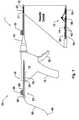
- FIG. 1A system 1 for repairing a meniscus according to embodiments of the present invention is illustrated in FIG. 1 .
- the system 1includes an applicator 10 that is constructed and arranged to deploy a suture 12 to the meniscus.
- the suture 12generally includes a flexible portion 58 and a pair of anchors 60, 70. The suture 12 will be discussed in greater detail below.
- the application 10includes a body portion 14 that defines a handle 16 that is configured to be grasped by the user.
- the body portion 14 of the applicator 10receives a cannula 18 that extends from the body portion 14 in a direction that is away from the handle 16.
- the body portion 14 and cannula 18may be constructed and arranged like those described and shown in U.S. Patent 5,928,252 , entitled Device and Method for Driving a Needle and Meniscal Repair. Because the inner workings of the body portion 14 are not related to the present invention, they are not described in detail herein.
- the applicator 10also includes a needle 20 that is connected to a distal end of the cannula 18.
- the needle 20may be considered to be a part of the cannula 18 itself.
- the needle 20will be described in greater detail below.
- the applicator 10also includes a pusher 23 that includes a hollow rod 24 that extends through the body portion 14, the cannula 18, and is slidingly received by the needle 20.
- a knob 26is attached to one end of the rod 24 and a spacer 28 with a tab 29 is disposed between the knob 26 and a proximal end 15 of the body portion 14 so that the movement of the knob 26 relative to the body portion 14 and, hence, movement of the rod 24 relative to the needle 20, may be limited to prevent premature ejection of one of the anchors 60 prior to the placement of the other anchor 70, as described in further detail below.
- a trigger 30is connected to and extends from the body portion 14, as shown in FIG. 1 . The trigger 30 is configured to manually control the advancement of the rod 24 within the cannula 18.
- a side lever 32is connected to the body portion so as to be pivotable thereon. Operation of the side lever 32 will be discussed in greater detail below.
- a depth penetration limiter 21is placed over the distal end of the cannula 18 so as to partially cover the needle 20.
- the limiter 21provides the user with a visualization of the depth of the needle 20 in the tissue to avoid neurovascular injury.
- An outer sheath 22is placed over the limiter 21 to aid in the insertion of the cannula 18 into the incision already created in the patient.
- the outer sheath 22is preferably designed to partially surround the limiter 21 so that the user may still see at least a portion of the limiter 21 when the needle 20 is being inserted into the incision.
- the outer sheath 22is removed by the user once the cannula 18 has been inserted into the incision site.
- the needle 20aincludes a sleeve 34a that is attached to the cannula 18 at a proximal end.
- the needle 20aalso includes a distal end 36a that is connected to the sleeve 34a and is constructed and arranged to be inserted into a meniscus or a tissue.
- the distal end 36ais substantially straight and includes a point 38a for piercing the meniscus or tissue and a slot 40a, which allows for the flexible portion 58 of the suture 12 to extend out of the needle 20a.
- the distal end 36a of the needle 20aalso includes a cutting surface 37a that is constructed and arranged to cut excess suture 12, which will be described in greater detail below.
- a cutting sheath 35a that at least partially surrounds the distal end 36amay also be provided.
- the cutting sheath 35acompletely surrounds the circumference of the distal end 36a.
- the cutting sheath 35amay only partially surround the distal end 36a.
- the cutting sheath 35ais configured to be slidable relative to the distal end 36a so that it may be moved longitudinally along the distal end 36a toward the point 38a, and then moved back again toward the sleeve 34a.
- the cutting sheath 35amay include a tab that extends outward from the needle 20a so that the user may manipulate the cutting sheath 35a via the tab.
- the cutting sheath 35aincludes at least one cutting surface 33a that is constructed and arranged to cut excess suture 12, which will be described in greater detail below.
- the distal end 36ais configured to hold the pair of anchors 60, 70 of the suture 12.
- the needle 20amay include a dimple 39a located near the point 38a to assist in seating the anchors 60, 70 prior to deployment of the anchors 60, 70 from the needle 20a, as will be described in greater detail below.
- the needle 20ais preferably manufactured from stainless steel, and is sized to withstand insertion through the implant and the meniscus substantially without bending or buckling.
- FIGs. 5-7Another embodiment of a needle 20b that may be used as the needle 20 in the applicator 10 is shown in FIGs. 5-7 .
- the needle 20bincludes a sleeve 34b that is attached to the cannula 18 at a proximal end.
- the needle 20balso includes a distal end 36b that is connected to the sleeve 34b and is constructed and arranged to be inserted into a meniscus or a tissue.
- the distal end 36bis curved such that it extends at an angle ⁇ relative to the sleeve 34b.
- the angle ⁇may be about 15-45°, and is preferably about 30°.
- the distal end 36balso includes a point 38b for piercing the meniscus or tissue and a slot 40b, which allows for portions of the suture 12 to extend out of the needle 20b.
- the distal end 36b of the needle 20balso includes at least one cutting surface 37b that is constructed and arranged to cut excess suture 12.
- a cutting sheath 35b that at least partially surrounds the distal end 36bmay also be provided.
- the cutting sheath 35bcompletely surrounds the circumference of the distal end 36b.
- the cutting sheath 35bmay only partially surround the distal end 36b.
- the cutting sheath 35bis configured to be slidable relative to the distal end 36b so that it may be moved longitudinally along the distal end 36b toward the point 38b, and back again to the sleeve 34b.
- the cutting sheath 35bmay include a tab that extends outward from the needle 20b so that the user may manipulate the cutting sheath 35b via the tab.
- the cutting sheath 35bincludes a cutting surface 33b that is constructed and arranged to cut excess suture 12.
- the distal end 36bis also configured to hold the pair of anchors 60, 70.
- the needle 20bmay also include a dimple 39b located near the point 38b to assist in seating the anchors 60, 70 prior to deployment.
- the needle 20bis preferably manufactured from stainless steel, and is sized to withstand insertion through the implant and the meniscus substantially without bending or buckling.
- the rod 24is hollow and is configured to receive the flexible portion 58 of the suture 12 that extends away from the needle 20.
- the knob 26includes a hole for receiving the rod 24, so that the flexible portion 58 of the suture 12 may extend through the knob 26 as well.
- a distal portion of the rod 24includes a pair of slots 42 that are configured to allow the flexible portion 58 of the suture 12 to be threaded out of the rod 24 via one slot 42 (the distal slot) and back into the rod 24 via the other slot 42 (the proximal slot), as represented by an exposed portion 44 of the flexible portion 58 of the suture 12.
- the rod 24may be flexible so that it may be used with the embodiment of the needle 20b described above.
- FIGs. 9-11illustrate an embodiment of an anchor 46 that may be used as the anchors 60, 70 of the suture 12.
- the anchor 46includes a tab 48 that extends upward from a body 50.
- the body 50has opposing ends 51 that are substantially perpendicular to a longitudinal axis LA of the anchor 46.
- a hole 52 that is centered on the longitudinal axis LAextends through the body 50 and the tab 48 where the body 50 and tab 48 are connected. Otherwise, the body 50 includes a hollowed out half-cylinder 53 at portions where the tab 48 is not connected.
- the anchor 46is preferably made out of a bioabsorbable polymer, such as poly(L-lactide).
- FIGs. 12-14Another embodiment of an anchor 54 for use in the suture 12 of the system 1 is shown in FIGs. 12-14 .
- the anchor 54is a solid rod with a pair of holes 56 that extend substantially perpendicularly through the longitudinal axis of the rod.
- the holes 56are sized to receive a flexible portion of the suture 12.
- a recessed channel 57is located between the holes 56 to seat the flexible portion 58 of the suture 12.
- the anchor 54is preferably made out of a bioabsorbable polymer, such as poly(L-lactide).
- the anchormay include at least one barb that is formed from or connected to a main body portion of the anchor.
- the barbmay be constructed and arranged to be biased to an orientation in which a free end of the barb extends away from the body, yet is oriented such that the free end is near the body when suitable pressure is applied to the barb.
- anchors 60, 70will be for the anchor 46 illustrated in FIGs. 9-11 , although it is understood that the anchor 54 of FIGs. 12-14 may be used with slight modifications to the language used to describe the assembly of the suture 12. Such modifications would be readily appreciated by one of skill in the art and are therefore not described herein.
- FIGs. 15-23show the various stages of an example of assembling the suture 12 of the system 1 of FIG. 1 .
- FIG. 15shows the flexible portion 58 of the suture 12 with one anchor 60 threaded thereon.
- FIG. 16shows a loop 62 and a knot 64 that closes the loop 62, with the anchor 60 being located within the loop 62.
- the knot 64is preferably a self-locking slide knot. Methods for tying a self-locking slide knot are described in, for example, " A New Clinch Knot,” Weston, P.V., Obstetrics & Gynecology, Vol. 78, pp.
- FIG. 17Note that the Figures are not necessarily drawn to scale. This distance is only meant to be an example and is not intended to be limiting in any way.
- the flexible portion 58 of the suture 12is tied off with one hitch knot 74 on the anchor 70, as shown in FIG. 18 .
- a needle 72is threaded with the remainder of the flexible portion 58.
- the end of the flexible portion 58 with the needle 72is passed through the center of the suture of the hitch knot twice to hold the hitch knot 74 in place, as shown in FIGs. 20 and 21 .
- the excess flexible portion 58is cut, leaving approximately 2 mm as a tail.
- the tip of the flexible portion 58may be melted to prevent fraying of the suture 12.
- An assembled suture 12 before it is loaded into the applicator 10is shown in FIG. 26 .
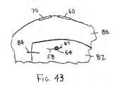
- FIG. 24shows a damaged meniscus 80 having a rim 81, and an implant 82 positioned adjacent the damaged part of the meniscus 80.
- the implant 82may be any type of implant 82 suitable for such meniscus repair.
- the implant 82includes collagen.
- the implant 82includes the CMI, a collagen-based meniscus implant.
- the implant 82 illustrated in the Figureshas already been cut to the appropriate size. Both ends of the implant 82 may be temporarily stapled or sutured using conventional means to hold the implant 82 in place while it is being secured to the meniscus 80.
- FIG. 25shows a pair of staples 84, or sutures, holding the implant 82 in place.
- the cannula 18, with the needle 20a attachedis inserted into the body portion 14 of the applicator 10.
- the needle 20a of FIGs. 2-4is shown.
- the needle 20bmay also be used in the same way.
- the illustrated and described embodimentsare not intended to be limiting in any way. While holding down the side lever 32 with a finger or a thumb, the rod 24 of the pusher 23 is inserted by the user into the proximal end 15 of the body portion 14 until the end of the rod 24 extends past the point 38a of the needle 20a with the slots 42 facing upward, as shown in FIG. 27 .
- an end 59 of the suture 12 that is opposite the anchor 70is threaded though the rod 24 of the pusher 23 at the distal end 36a of the needle 20a.
- the end 59 of the suture 12is laced through the distal end of the rod 24, pulled out of the rod 24 at the distal slot 42, threaded back into the rod 24 at the proximal slot 42, thereby leaving the exposed portion 44 outside of the rod 24.
- the end 59 of the suture 12may extend several inches outside the pusher 23 beyond the proximal end 15 of the body portion 14 of the applicator 10 so that the user may grasp the suture 12 during the implant attachment procedure, which will be described below.
- the userpresses the side lever 32 and retracts the pusher 23 back into the needle 20a, as shown in FIG. 29 , to locate the slots 42 and the exposed portion 44 of the suture 12 before the proximal end of the needle slot 40a, as shown in FIG. 30 .
- the anchor 60is inserted into the distal end 36a of the needle 20a, and is followed by the anchor 70, as shown in FIGs. 30 and 31 .
- the end 59 of the flexible portion 58 that extends out of the pusher 23 at the proximal end 15 of the body portion 14 of the applicator 10may be pulled so that the knot 64 is generally located on a side of the anchor 60 that is opposite the other anchor 70, as shown in FIG.
- a portion of the flexible portion 58may extend outside of the cannula 18 via the slot 40a of the needle 20a, as shown in FIGs. 30 and 31 .
- the pulling of the trigger 30causes the anchor 70, the anchor 60, and the knot 64 to be deployed in that order.
- the userplaces the spacer 28 between the knob 26 and the proximal end 15 of the body portion 14 so that the advancement of the anchor 60 will be limited until the placement of the anchor 70 is complete.
- the userthen inserts the depth penetration limiter 21 and the outer sheath 22 over the distal end of the cannula 18 so as to cover the needle 20 during insertion of the needle 20 into the incision site.
- the outer sheath 22may be removed from the cannula 18.
- the use of the spacer 28, the outer sheath 22, and the depth penetration limiter 21should be considered optional.
- the illustrated exampleis not intended to be limiting in any way.
- the usermay then advance the anchors 60, 70 until the anchor 70 is located near the point 38a of the needle 20a, without extending out of the needle 20a.
- the dimple 39amay be used to assist with the placement of the anchor 70.
- the usershould feel a slight resistance to the advancement of the anchor 70, which signals the user to stop advancing the pusher 23.
- the use of the dimple 39ashould be considered to be optional.
- the illustrated embodimentis not intended to be limiting in any way.
- the userWhile gripping the handle 16 and the trigger 30 on the applicator 10, the user inserts the needle 20a into a patient at an incision site so that the needle 20a may then be inserted through the implant 82 and through the meniscus 80 at a first location 86, preferably near the center of the implant 82, to a side opposite the insertion site, as shown in FIG. 32 .
- the usershould be sure that the hitch knot 74 on the anchor 70 has passed through the meniscus 80, as shown in FIG. 32 .
- the userthen advances the pusher 23 via the trigger 30 until the anchor 70 is pushed outside the needle 20a, as shown in FIG. 33 .
- the usershould be careful to not advance the pusher 23 further to avoid the premature deployment of the anchor 60.
- the spacer 28assists in preventing the premature deployment of the anchor 60.
- the dimple 39a that is located near the point 38a of the needle 20amay also be used to provide the user with tactile feedback that the anchor 60 has been advanced to its proper pre-deployment position.
- the userthen retracts the needle 20a slowly from the meniscus 80 and the implant 82, leaving the anchor 70 behind on the opposite side of the meniscus 80.
- the anchor 60will remain inside the needle 20a. If the user hasn't already done so, the user next advances the anchor 60 until the anchor 60 is located near the point 38a of the needle 20a. Again for embodiments that include the dimple 39a, the dimple 39a may be used to guide the user to correctly position the anchor 60.
- the userWhile gripping the handle 16 and the trigger 30 on the applicator 10, the user inserts the needle 20a though the implant 82 and through the meniscus 80 at a second location 88, which is preferably near the first location 86, until the center of the anchor 60 is outside the opposite side of the meniscus 80, as shown in FIG. 35 . If the user hasn't already done so, the user next removes the spacer 28 from the rod 24 by grasping the tab 29 and pulling the spacer 28 away from the rod 24. The user then advances the pusher 23 until the anchor 60 is pushed outside the needle 20a, as shown in FIG. 36 . The user then retracts the needle 20a, thereby leaving the anchor 60 on the opposite side of the meniscus 80, as shown in FIG. 37 .
- the usermay then advance the pusher 23 via the trigger 30 so that the rod 24 extends approximately 1 cm beyond the point 38a of the needle 20a, as shown in FIG. 38 . While gripping the handle 16 and the trigger 30 of the applicator 10, the user then holds the tip of the rod 24 against the knot 64 and pushes the knot 64 to the surface of the implant 82, being careful not to push the knot 64 through the implant 82.
- the usercontinues to grip the handle 16 and the trigger 30 while gently pulling on the end 59 of the flexible portion 58 of the suture 12 at the proximal end 15 of the body portion 14 of the applicator 10 until slack in the suture 12 is taken up, and the anchors 60, 70 sit flat against the meniscus 80, as shown in FIGs. 39 and 40 .
- the usermay extend the rod 24 of the pusher 23 out of the needle 20a approximately 1 cm.
- the usermay then rotate the pusher 23 up to approximately 180°, or until the slots 42 and the exposed portion 44 of the suture 12 are positioned to come into contact with the cutting surface 37a when the pusher 23 is pulled back toward the proximal end 15 of the body portion 14 of the applicator 10, as shown in FIG. 41 .
- Holding the end 59 of the flexible portion 58 that extends out of the proximal end 15, the usermay shear the exposed portion 44 of the suture 12 against the cutting surface 37a by sliding the pusher 23 longitudinally against the cutting surface 37a, as shown in FIG. 41 , thereby leaving a short tail 67 near the knot 64, as shown in FIG. 43 .
- the pusher 23may have to be moved back and forth against the cutting surface 37a before the suture 12 is fully cut.
- the usermay shear the exposed portion 44 of the suture 12 against the cutting surface 33a by sliding the cutting sheath 35a along the distal end 36a and toward the point 38a of the needle 20a, as shown in FIG. 42 , thereby leaving a short tail 67 near the knot 64, as shown in FIG. 43 .
- the cutting sheath 35amay have to be moved back and forth along the distal end of the needle 20a before the suture 12 is fully cut.
- the aforementioned system 1 and methodprovide an all-inside suture fixation to the implant and meniscus, because the needle 20a of the applicator 10 has not been removed from the patient's body between the deployment of the anchor 70, the pushing of the knot 64, and the cutting of the excess flexible portion 58 of the suture 12. This may be beneficial to the patient because it may reduce the time the applicator 10 is in the patient's body, and allows for a single, small entry point of the needle 20a, at the incision, into the patient's body.
- the usermay then repeat the steps shown in FIGs. 32-43 for any remaining sutures 12 that are needed to complete the fixation of the implant 82 to the meniscus 80. Generally, it may take three or more sutures 12 to secure the implant 82.
- the usermay remove the body portion 14 of the applicator 10 and pusher 23 from the cannula 18, and trim the excess flexible portion 58 of the suture 12 with scissors, or some other cutting device.
- the illustrated embodimentsare not intended to be limiting in any way.
- one or both of the anchors 60, 70may be the anchor described above that includes one or more barbs. This allows the user to advance the pusher 23 via the trigger 30 only until a distal end of the anchor is located adjacent the point of the needle 20 in an orientation in which the barb is no longer engaged by the wall of the needle 20. When the anchor is in this position, the wall of the needle 20 is no longer exerting pressure on the barb, thereby allowing the barb to be biased outward and away from the body of the anchor. The barb may then be used to engage the anchor with the meniscus 80 so that when the user pulls the needle 20 back through the meniscus 80 and the implant 82, the entirety of the anchor will pull out of the needle 20 without further advancement of the pusher 23.
- the needle 20may be designed such that the tab 48 on the anchor 46 may be used to engage the anchor 46 with the meniscus 80 before the anchor 46 exits the needle 20. This allows the entirety of the anchor 46 to be pulled out of the needle 20 when the needle 20 is pulled back through the meniscus 80, rather than pushing the entirety of the anchor 46 out of the needle 20 with the pusher 23, as described in the examples above.
- the needle 20may be inserted through the meniscus 80 a first location near the tear.
- the first anchor 70 of the suture 12may then be delivered to an opposite side of the meniscus 80, and the needle 20 retracted from the meniscus 80, without pulling out of the body.
- the needlemay then be inserted through the meniscus 80 at a second location on an opposite side of the tear as the first location.
- the second anchor 60 of the suture 12may then be delivered to the opposite side of the meniscus 80. Once the second anchor 60 is in the proper position, the user may then push the knot 64 to a surface of the meniscus 80 to tighten the suture. The excess of the flexible portion 58 of the suture 12 may then be cut with any of the cutting methods described above.
- the specificationmay have presented the method and/or process of the present disclosure as a particular sequence of steps. However, to the extent that the method or process does not rely on the particular order of steps set forth herein, the method or process should not be limited to the particular sequence of steps described. For example, any number of sutures may be prepared ahead of time. In addition, the advancement of the anchors within the cannula may occur before or after needle insertion. In addition, the delivery of the second anchor may not require that the needle be fully withdrawn; for example when two anchors are to be delivered through a single insertion site. As one of ordinary skill in the art would appreciate, other sequences of steps may be possible.
Landscapes
- Health & Medical Sciences (AREA)
- Surgery (AREA)
- Life Sciences & Earth Sciences (AREA)
- Medical Informatics (AREA)
- Animal Behavior & Ethology (AREA)
- Engineering & Computer Science (AREA)
- Biomedical Technology (AREA)
- Heart & Thoracic Surgery (AREA)
- Veterinary Medicine (AREA)
- Molecular Biology (AREA)
- Nuclear Medicine, Radiotherapy & Molecular Imaging (AREA)
- General Health & Medical Sciences (AREA)
- Public Health (AREA)
- Rheumatology (AREA)
- Surgical Instruments (AREA)
- Materials For Medical Uses (AREA)
- Prostheses (AREA)
Description
- The present invention relates to a system for repairing a tear in a meniscus in a body with a suture.
- The present invention relates generally to a system for attaching an implant during meniscal repair and for other soft tissue repair. More particularly, the present invention relates to a system for an all-inside suture fixation device designed for the placement of surgical anchors for the attachment of an implant to the meniscus and for soft tissue repair. The present invention also relates to a system designed to reduce, or bring into close approximation, pieces of torn or damaged soft tissue to facilitate tissue repair and healing.
- There are current procedures for surgical attachment of a soft tissue implant in a joint, such as an autograft, allograft, or xenograft tissue or other compatible tissues and/or devices. Such implants may be bioresorbable and/or non-resorbable, synthetic and/or non-synthetic. One example of a bioresorbable implant is the ReGen® CMI™, a collagen-based meniscus implant, the surgical attachment of which can involve techniques that are difficult to master. There is a need, therefore, for a fixation device to facilitate a faster, easier to use method for attaching an implant to a host tissue. Suture fixation devices, such as the FAST-FIX™ and RAPIDLOC™, which were designed to repair tears in meniscus tissue, have certain limitations in their delivery of anchors to attach an implant to the meniscal rim in that they may cause unnecessary destruction to the implant and require additional instruments and steps that are not integral to the device itself. The needle used to pass the anchor through an implant and through the meniscal rim punctures the implant in a manner that may lead to tearing of the implant matrix. There is a need, therefore, for a dimensionally smaller device that employs a smaller needle that delivers a less destructive anchor through an implant and the meniscus, thereby reducing the size of the puncture hole in the implant and the potential for tearing the implant matrix.
- There is a need, therefore, for a fixation device that includes an integrated knot pusher to secure the delivered anchor, and optionally, also includes a suture cutter for use after one or more anchors have been secured. Techniques that require separate instruments for knot pushing and suture cutting are less efficient, and require greater skill, time, and additional manipulation at the surgical site.
- Prior art devices and methods for suture fixation of an implant to soft tissue within a joint typically tear the matrix of the implant during needle insertion and/or anchor delivery. There remains a need for a device and method for fixing an implant to soft tissue that can insert anchors through the implant and host tissue with minimal destruction of the implant, in a well-controlled and easy manner. Also, there remains a need for a device and method for fixing a collagen-based meniscus implant to the host meniscal tissue, in a well-controlled and easy manner, whereby the needle and anchor insertion cause minimal to no destruction of the collagen-based meniscus implant. Also, there remains a need for a device and method for fixing a collagen-based meniscus implant to the host meniscal tissue that puts adequate tension between the anchors in a well-controlled and easy manner.
US-A-2003/0158604 describes method and devices for annulus disc repair with and without the use of a patch or stent. The methods and devices are particularly suited to the repair and/or reconstruction of spinal disc wall (annulus) after surgical invasion or pathologic rupture, with reduced failure rate as compared to conventional surgical procedures. - According to an aspect of the present invention, there is provided a system for repairing a meniscus in a body with a suture, the system comprising: a suture including a first anchor, a second anchor, and a flexible portion connecting the first anchor and the second anchor, the flexible portion including a self-locking slide knot between the first anchor and the second anchor; a needle having a longitudinal extending bore and an open end, the bore being configured to receive the first anchor and the second anchor; and a pusher configured to be movable within the bore of the needle, the pusher being configured to (1) discharge the first anchor and the second anchor, and (2) push the self-locking slide knot after the discharge of the second anchor; characterised in that the system is configured to: insert the needle through the meniscus at a first location; deliver the first anchor to an opposite side of the meniscus, retract the needle from the meniscus; insert the needle through the meniscus at a second location on an opposite side of the tear as the first location; deliver the second anchor of the suture to the opposite side of the meniscus; and push the self-locking slide knot to contact a surface of the meniscus; wherein delivering the second anchor and pushing the self-locking knot are completed without removing the needle from the body. In examples, a fixation delivery system is an integrated design for use with the multiple elements required for suture fixation when attaching a soft tissue implant to host tissue or when performing tissue repair procedures in general. The system and method achieves the deployment of anchors into soft tissue and knot pushing with the use of a single instrument, and also provides for suture cutting within that single instrument. The hollow needle applicator and anchors are of smaller dimensions than current applicators and anchors to minimize the damage to the implant during needle insertion and anchor deployment.
- In an embodiment, the applicator for deployment of the anchors includes a hollow needle or cannula having a longitudinal extending bore and an open end, into which a suture, which includes two surgical anchors, is loaded. The first anchor and the second anchor are connected via a flexible portion of the suture. The flexible portion includes a self-locking slide knot located between the first anchor and the second anchor. The needle is inserted into an incision already made in the patient's body, through the implant, and through the host meniscus to the outside rim of the meniscus, or through the soft tissue requiring repair. Alternatively, the needle may penetrate directly through the patient's skin and into the joint capsule comprising the knee. The first anchor is ejected from the tip of the hollow needle by gripping the handle of the applicator and pulling the trigger, which advances a push rod within the hollow needle. The anchor is released from the open end of the needle to seat firmly on the surface of the soft tissue or rim of the meniscus (i.e., the meniscus rim). The needle is removed from the initial insertion site and inserted through the implant and through the meniscus or host soft tissue a short distance from the initial insertion point, without removing the needle from the patient's body. The second anchor is deployed by gripping the trigger of the applicator to advance the push rod a second time and release the second anchor. The needle is withdrawn or retracted from the second insertion site, thereby leaving two anchors positioned on the outside rim of the meniscus. The push rod, or pusher, functions as a knot pusher and can be used to push a self-locking slide knot, located on the flexible portion between the first and second anchors, until the knot is flush with the implant. Also, the flexible portion may be tightened by hand until adequate tension is applied to hold the pair of anchors firmly in place. Excess length of the flexible portion/suture can be cut using a cutter, which may be in the form of a suture cutting surface on the applicator. Again, the system is designed so that the deployment of the anchors, the pushing of the self-locking slide knot, and the optional cutting may all be completed without removing the needle from the patient's body.
- In an embodiment, a system for repairing a meniscus is provided. The system includes a suture that includes a first anchor, a second anchor, and a flexible portion connecting the first anchor and the second anchor. The flexible portion includes a self-locking slide knot between the first anchor and the second anchor. The system also includes a needle having a longitudinal extending bore and an open end. The bore is configured to receive the first anchor and the second anchor. The system further includes a pusher configured to be movable within the bore of the needle. The pusher is configured to (1) discharge the first anchor and the second anchor, and (2) push the self-locking slide knot after the discharge of the second anchor.
- As an example, a method for repairing a meniscus is provided. The method includes providing a system for repairing a meniscus. The system includes a suture that includes a first anchor, a second anchor, and a flexible portion connecting the first anchor and the second anchor. The flexible portion includes a self-locking slide knot between the first anchor and the second anchor. The system also includes a needle having a longitudinal extending bore and an open end. The bore is configured to receive the first anchor and the second anchor. The system further includes a pusher configured to be movable within the bore of the needle. The pusher is configured to (1) discharge the first anchor and the second anchor, and (2) push the self-locking slide knot after the discharge of the second anchor. The method also includes providing an implant, passing the needle of the system through the implant and the meniscus at a first location to deliver the first anchor to an opposite side of the meniscus, retracting the needle from the meniscus and the implant, passing the needle of the system through the implant and the meniscus at a second location to deliver the second anchor to the opposite side of the meniscus, and pushing the self-locking slide knot to a surface of the implant.
- In an example, a method for repairing a meniscus in a body with an implant and a suture is provided. The method includes inserting a needle through the implant and the meniscus at a first location, delivering a first anchor of the suture to an opposite side of the meniscus, retracting the needle from the meniscus and the implant, inserting the needle through the implant and the meniscus at a second location, and delivering a second anchor of the suture to the opposite side of the meniscus. The second anchor is connected to the first anchor with a flexible portion of the suture. The method also includes pushing a self-locking slide knot located along the flexible portion between the first anchor and the second anchor to a surface of the implant. The delivering of the second anchor and the pushing the self-locking knot are completed without removing the needle from the body.
- In an example, a method for repairing a tear in a meniscus in a body with a suture is provided. The method includes inserting a needle through the meniscus at a first location, delivering a first anchor of the suture to an opposite side of the meniscus, retracting the needle from the meniscus, inserting the needle through the meniscus at a second location on an opposite side of the tear as the first location, and delivering a second anchor of the suture to the opposite side of the meniscus. The second anchor is connected to the first anchor with a flexible portion of the suture. The method further includes pushing a self-locking slide knot located along the flexible portion between the first anchor and the second anchor to a surface of the meniscus. The delivering of the second anchor and the pushing of the self-locking knot are completed without removing the needle from the body.
- In an embodiment, an applicator for delivering a suture to an implant for repairing a meniscus in a body is provided. The suture includes a first anchor, a second anchor, and a flexible portion that connects the first anchor to the second anchor. The applicator includes a needle having a longitudinal bore. The longitudinal bore is configured to receive the first anchor and the second anchor. The applicator also includes a pusher for pushing the first anchor and the second anchor out of the longitudinal bore of the needle. The pusher is configured to receive the flexible portion therein and expose a portion of the flexible portion of the suture. The applicator also includes a cutting surface configured to cut the suture.
- With minor alterations, this anchor delivery system device may be used in other procedures for soft-tissue repair, and most preferably for arthroscopic procedures. Examples include, but are not limited to use in reparative procedures for soft tissue damage in joints, securing tissue grafts, and attaching resorbable implants and synthetic scaffolds to host tissue.
- Other aspects, features, and advantages of the present invention will become apparent from the following detailed description, the accompanying drawings, and the appended claims.
- Features of the invention are shown in the drawings, in which like reference numerals designate like elements. The drawings form part of this original disclosure, in which:
FIG. 1 is a side view of an embodiment of a system for all-inside suture fixation for implant attachment and soft tissue repair of the present invention;FIG. 2 is a top view of an embodiment of a needle of the system ofFIG. 1 ;FIG. 3 is a side view of the needle ofFIG. 2 ;FIG. 4 is a cross-sectional view taken along line 4-4 inFIG. 2 ;FIG. 5 is a side view of another embodiment of the needle for the system ofFIG. 1 ;FIG. 6 is a top view of the needle ofFIG. 5 ;FIG. 7 is a cross-sectional view taken along line 7-7 inFIG. 6 ;FIG. 8 is a side view of a pusher of the system ofFIG. 1 ;FIG. 9 is a top view of an anchor of a suture of the system ofFIG. 1 ;FIG. 10 is an end view of the anchor ofFIG. 9 ;FIG. 11 is a side view of the anchor ofFIG. 9 ;FIG. 12 is a top view of another embodiment of an anchor of the suture for the system ofFIG. 1 ;FIG. 13 is an end view of the anchor ofFIG. 12 ;FIG. 14 is a side view of the anchor ofFIG. 12 ;FIG. 15 is a view of an anchor threaded onto a flexible portion of the suture of the system ofFIG. 1 ;FIG. 16 is a view of the anchor and the flexible portion ofFIG. 15 with a loop and a self-locking slide knot formed in the flexible portion;FIG. 17 is a view of the anchor and the flexible portion ofFIG. 16 with a second anchor positioned on the flexible portion;FIG. 18 is a partial view of the second anchor and the flexible portion ofFIG. 17 ;FIG. 19 is a partial view of the second anchor and the flexible portion ofFIG. 17 with a needle threaded on the flexible portion;FIG. 20 is a partial view of the needle threaded on the flexible portion and passing through the center of the suture at the second anchor;FIG. 21 is a partial view of the needle passing through the center of the suture at the second anchor a second time;FIG. 22 is a view of the anchor with a knot securing it to the flexible portion;FIG. 23 is a partial view of the flexible portion and the second anchor at one end thereof;FIG. 24 is a perspective view of a meniscus with an implant positioned on the meniscus;FIG. 25 is a view of the implant after it has been stapled to the meniscus;FIG. 26 is a view of the suture of the system ofFIG. 1 ;FIG. 27 is a top view of the needle with the pusher extended therefrom;FIG. 28 is a side view of the suture being threaded into the pusher and the needle;FIG. 29 is a side view of the suture further being threaded into the pusher and the needle;FIG. 30 is a top view of the needle with the suture loaded therein;FIG. 31 is a side view of the needle ofFIG. 30 ;FIG. 32 is a top view of the needle of the system ofFIG. 1 piercing the implant and meniscus ofFIG. 25 at a first location;FIG. 33 is a top view of the needle ofFIG. 32 after the first anchor has been ejected from the needle with the pusher;FIG. 34 is a perspective view of the needle ofFIG. 32 after it has been pulled back through the meniscus and implant;FIG. 35 is a top view of the needle ofFIG. 32 piercing the implant and meniscus ofFIG. 25 at a second location;FIG. 36 is a top view of the needle ofFIG. 35 after the second anchor has been ejected from the needle with the pusher;FIG. 37 is a top view of the needle ofFIG. 35 after is has been pulled back through the meniscus and implant;FIG. 38 is a top view of the needle ofFIG. 37 with the pusher extended out of the needle;FIG. 39 is a top view of the needle ofFIG. 38 with the pusher pushing the knot against the implant;FIG. 40 is a top view of the needle ofFIG. 39 after it has been pulled back following knot pushing and suture tensioning;FIG. 41 is a side view of the needle ofFIG. 40 with the suture exposed to the needle cutting surface;FIG. 42 is a side view of another embodiment of the needle ofFIG. 40 with the suture exposed to a cutting surface on a cutting sheath; andFIG. 43 is a top view of the repaired meniscus with the suture tightly in place.- A
system 1 for repairing a meniscus according to embodiments of the present invention is illustrated inFIG. 1 . Thesystem 1 includes anapplicator 10 that is constructed and arranged to deploy asuture 12 to the meniscus. Thesuture 12 generally includes aflexible portion 58 and a pair ofanchors suture 12 will be discussed in greater detail below. - The
application 10 includes abody portion 14 that defines ahandle 16 that is configured to be grasped by the user. Thebody portion 14 of theapplicator 10 receives a cannula 18 that extends from thebody portion 14 in a direction that is away from thehandle 16. Thebody portion 14 and cannula 18 may be constructed and arranged like those described and shown inU.S. Patent 5,928,252 , entitled Device and Method for Driving a Needle and Meniscal Repair. Because the inner workings of thebody portion 14 are not related to the present invention, they are not described in detail herein. - The
applicator 10 also includes aneedle 20 that is connected to a distal end of the cannula 18. Of course, theneedle 20 may be considered to be a part of the cannula 18 itself. Theneedle 20 will be described in greater detail below. Theapplicator 10 also includes apusher 23 that includes ahollow rod 24 that extends through thebody portion 14, the cannula 18, and is slidingly received by theneedle 20. Aknob 26 is attached to one end of therod 24 and aspacer 28 with atab 29 is disposed between theknob 26 and aproximal end 15 of thebody portion 14 so that the movement of theknob 26 relative to thebody portion 14 and, hence, movement of therod 24 relative to theneedle 20, may be limited to prevent premature ejection of one of theanchors 60 prior to the placement of theother anchor 70, as described in further detail below. Atrigger 30 is connected to and extends from thebody portion 14, as shown inFIG. 1 . Thetrigger 30 is configured to manually control the advancement of therod 24 within the cannula 18. Aside lever 32 is connected to the body portion so as to be pivotable thereon. Operation of theside lever 32 will be discussed in greater detail below. - As shown in
FIG. 1 , adepth penetration limiter 21 is placed over the distal end of the cannula 18 so as to partially cover theneedle 20. Thelimiter 21 provides the user with a visualization of the depth of theneedle 20 in the tissue to avoid neurovascular injury. Anouter sheath 22 is placed over thelimiter 21 to aid in the insertion of the cannula 18 into the incision already created in the patient. Theouter sheath 22 is preferably designed to partially surround thelimiter 21 so that the user may still see at least a portion of thelimiter 21 when theneedle 20 is being inserted into the incision. Theouter sheath 22 is removed by the user once the cannula 18 has been inserted into the incision site. - One embodiment of a
needle 20a that may be used as theneedle 20 inFIG. 1 is shown inFIGs. 2-4 . As shown, theneedle 20a includes asleeve 34a that is attached to the cannula 18 at a proximal end. Theneedle 20a also includes adistal end 36a that is connected to thesleeve 34a and is constructed and arranged to be inserted into a meniscus or a tissue. Thedistal end 36a is substantially straight and includes apoint 38a for piercing the meniscus or tissue and aslot 40a, which allows for theflexible portion 58 of thesuture 12 to extend out of theneedle 20a. As shown in the Figures, thedistal end 36a of theneedle 20a also includes a cuttingsurface 37a that is constructed and arranged to cutexcess suture 12, which will be described in greater detail below. - As shown in
FIGs. 2-4 , a cuttingsheath 35a that at least partially surrounds thedistal end 36a may also be provided. In the illustrated embodiment, the cuttingsheath 35a completely surrounds the circumference of thedistal end 36a. In other embodiments, the cuttingsheath 35a may only partially surround thedistal end 36a. The cuttingsheath 35a is configured to be slidable relative to thedistal end 36a so that it may be moved longitudinally along thedistal end 36a toward thepoint 38a, and then moved back again toward thesleeve 34a. The cuttingsheath 35a may include a tab that extends outward from theneedle 20a so that the user may manipulate the cuttingsheath 35a via the tab. As shown, the cuttingsheath 35a includes at least onecutting surface 33a that is constructed and arranged to cutexcess suture 12, which will be described in greater detail below. - As shown in
FIG. 4 , thedistal end 36a is configured to hold the pair ofanchors suture 12. Theneedle 20a may include adimple 39a located near thepoint 38a to assist in seating theanchors anchors needle 20a, as will be described in greater detail below. Theneedle 20a is preferably manufactured from stainless steel, and is sized to withstand insertion through the implant and the meniscus substantially without bending or buckling. - Another embodiment of a
needle 20b that may be used as theneedle 20 in theapplicator 10 is shown inFIGs. 5-7 . As shown, theneedle 20b includes asleeve 34b that is attached to the cannula 18 at a proximal end. Theneedle 20b also includes adistal end 36b that is connected to thesleeve 34b and is constructed and arranged to be inserted into a meniscus or a tissue. Thedistal end 36b is curved such that it extends at an angle α relative to thesleeve 34b. The angle α may be about 15-45°, and is preferably about 30°. Thedistal end 36b also includes apoint 38b for piercing the meniscus or tissue and aslot 40b, which allows for portions of thesuture 12 to extend out of theneedle 20b. Thedistal end 36b of theneedle 20b also includes at least onecutting surface 37b that is constructed and arranged to cutexcess suture 12. - As shown in
FIGs. 5-7 , a cuttingsheath 35b that at least partially surrounds thedistal end 36b may also be provided. In the illustrated embodiment, the cuttingsheath 35b completely surrounds the circumference of thedistal end 36b. In other embodiments, the cuttingsheath 35b may only partially surround thedistal end 36b. The cuttingsheath 35b is configured to be slidable relative to thedistal end 36b so that it may be moved longitudinally along thedistal end 36b toward thepoint 38b, and back again to thesleeve 34b. The cuttingsheath 35b may include a tab that extends outward from theneedle 20b so that the user may manipulate the cuttingsheath 35b via the tab. As shown, the cuttingsheath 35b includes a cuttingsurface 33b that is constructed and arranged to cutexcess suture 12. - As shown in
FIG. 7 , thedistal end 36b is also configured to hold the pair ofanchors needle 20b may also include adimple 39b located near thepoint 38b to assist in seating theanchors needle 20a ofFIGs. 2-4 , theneedle 20b is preferably manufactured from stainless steel, and is sized to withstand insertion through the implant and the meniscus substantially without bending or buckling. - An embodiment of the
pusher 23 is shown in greater detail inFIG. 8 . Therod 24 is hollow and is configured to receive theflexible portion 58 of thesuture 12 that extends away from theneedle 20. Theknob 26 includes a hole for receiving therod 24, so that theflexible portion 58 of thesuture 12 may extend through theknob 26 as well. A distal portion of therod 24 includes a pair ofslots 42 that are configured to allow theflexible portion 58 of thesuture 12 to be threaded out of therod 24 via one slot 42 (the distal slot) and back into therod 24 via the other slot 42 (the proximal slot), as represented by an exposedportion 44 of theflexible portion 58 of thesuture 12. This threading of thesuture 12 properly aligns the exposedportion 44 relative to therod 24 to facilitate the cutting of thesuture 12, which will be described in further detail below. As shown inFIG. 7 , therod 24 may be flexible so that it may be used with the embodiment of theneedle 20b described above. FIGs. 9-11 illustrate an embodiment of ananchor 46 that may be used as theanchors suture 12. As shown, theanchor 46 includes atab 48 that extends upward from abody 50. Thebody 50 has opposing ends 51 that are substantially perpendicular to a longitudinal axis LA of theanchor 46. Ahole 52 that is centered on the longitudinal axis LA extends through thebody 50 and thetab 48 where thebody 50 andtab 48 are connected. Otherwise, thebody 50 includes a hollowed out half-cylinder 53 at portions where thetab 48 is not connected. Theanchor 46 is preferably made out of a bioabsorbable polymer, such as poly(L-lactide).- Another embodiment of an
anchor 54 for use in thesuture 12 of thesystem 1 is shown inFIGs. 12-14 . As shown, theanchor 54 is a solid rod with a pair ofholes 56 that extend substantially perpendicularly through the longitudinal axis of the rod. Theholes 56 are sized to receive a flexible portion of thesuture 12. A recessedchannel 57 is located between theholes 56 to seat theflexible portion 58 of thesuture 12. Like theanchor 46, theanchor 54 is preferably made out of a bioabsorbable polymer, such as poly(L-lactide). - In another embodiment of an anchor that may be used as one or both of the
anchors suture 12, the anchor may include at least one barb that is formed from or connected to a main body portion of the anchor. The barb may be constructed and arranged to be biased to an orientation in which a free end of the barb extends away from the body, yet is oriented such that the free end is near the body when suitable pressure is applied to the barb. The use of such an anchor with thesystem 1 will be described in greater detail below. - Unless otherwise indicated herein, further discussions of the
anchors anchor 46 illustrated inFIGs. 9-11 , although it is understood that theanchor 54 ofFIGs. 12-14 may be used with slight modifications to the language used to describe the assembly of thesuture 12. Such modifications would be readily appreciated by one of skill in the art and are therefore not described herein. FIGs. 15-23 show the various stages of an example of assembling thesuture 12 of thesystem 1 ofFIG. 1 .FIG. 15 shows theflexible portion 58 of thesuture 12 with oneanchor 60 threaded thereon.FIG. 16 shows aloop 62 and aknot 64 that closes theloop 62, with theanchor 60 being located within theloop 62. Theknot 64 is preferably a self-locking slide knot. Methods for tying a self-locking slide knot are described in, for example, "A New Clinch Knot," Weston, P.V., Obstetrics & Gynecology, Vol. 78, pp. 144-47 (1991); "Physical Properties of Self Locking and Conventional Surgical Knots," Israelsson, L.A., et al., European Journal of Surgery, Vol. 160, No. 6-7, pp. 323-27 (1994); "Nicky's Knot-A New Slip Knot for Arthroscopic Surgery," De Beer, J.F., et al., Arthroscopy: The Journal of Arthroscopic and Relate Surgery, Vol. 14, No 1, pp. 109-110 (1998); "The Giant Knot: A New One-Way Self-Locking Secured Arthroscopic Slip Knot," Fleega, B.A., et al., Arthroscopy: The Journal of Arthroscopic and Relate Surgery, Vol. 15, No 4, pp. 451-52 (1999); "Arthroscopic Knot Tying Techniques," Nottage, W.M., et al., Arthroscopy: The Journal of Arthroscopic and Relate Surgery, Vol. 15, No 5, pp. 515-521 (1999); "The SMC Knot-A New Slip Knot With Locking Mechanism," Kim, S., et al., Arthroscopy: The Journal of Arthroscopic and Relate Surgery, Vol. 16, No 5, pp. 563-65 (2000); "Technical Note: A 'New' Arthroscopic Sliding Knot," Field, M.H., et al., Orthopedic Clinics of North America, Vol. 32, No. 3, pp. 525-26 (2001); "Arthroscopic Knot Tying," Kim, S., et al., Techniques in Shoulder & Elbow Surgery, Vol. 4, No. 2, pp. 35-43 (2003); "The PC Knot: A Secure and Satisfying Arthroscopic Slip Knot," Pallia, C.S., Arthroscopy: The Journal of Arthroscopic and Relate Surgery, Vol. 19, No 5, pp. 558-560 (2003); and "The Tuckahoe Knot: A Secure Locking Slip Knot," Wiley, W.B., et al., Arthroscopy: The Journal of Arthroscopic and Relate Surgery, Vol. 20, No 5, pp. 556-59 (2004).- Once the self-locking
slide knot 64 has been tied, anotheranchor 70 is slid onto theflexible portion 58 until it is located approximately 7 mm from theknot 64, as shown inFIG. 17 (note that the Figures are not necessarily drawn to scale). This distance is only meant to be an example and is not intended to be limiting in any way. Theflexible portion 58 of thesuture 12 is tied off with onehitch knot 74 on theanchor 70, as shown inFIG. 18 . - Next, as shown in
FIG. 19 , aneedle 72 is threaded with the remainder of theflexible portion 58. The end of theflexible portion 58 with theneedle 72 is passed through the center of the suture of the hitch knot twice to hold thehitch knot 74 in place, as shown inFIGs. 20 and 21 . As shown inFIG. 22 , the excessflexible portion 58 is cut, leaving approximately 2 mm as a tail. Finally, as shown inFIG. 23 , the tip of theflexible portion 58 may be melted to prevent fraying of thesuture 12. An assembledsuture 12 before it is loaded into theapplicator 10 is shown inFIG. 26 . FIG. 24 shows a damagedmeniscus 80 having arim 81, and animplant 82 positioned adjacent the damaged part of themeniscus 80. Theimplant 82 may be any type ofimplant 82 suitable for such meniscus repair. Preferably, theimplant 82 includes collagen. In an embodiment, theimplant 82 includes the CMI, a collagen-based meniscus implant. Theimplant 82 illustrated in the Figures has already been cut to the appropriate size. Both ends of theimplant 82 may be temporarily stapled or sutured using conventional means to hold theimplant 82 in place while it is being secured to themeniscus 80.FIG. 25 shows a pair ofstaples 84, or sutures, holding theimplant 82 in place.- To load the
suture 12 into theapplicator 10, the cannula 18, with theneedle 20a attached, is inserted into thebody portion 14 of theapplicator 10. In this embodiment, theneedle 20a ofFIGs. 2-4 is shown. However, it is understood that theneedle 20b may also be used in the same way. The illustrated and described embodiments are not intended to be limiting in any way. While holding down theside lever 32 with a finger or a thumb, therod 24 of thepusher 23 is inserted by the user into theproximal end 15 of thebody portion 14 until the end of therod 24 extends past thepoint 38a of theneedle 20a with theslots 42 facing upward, as shown inFIG. 27 . - Next, as shown in
FIG. 28 , anend 59 of thesuture 12 that is opposite theanchor 70 is threaded though therod 24 of thepusher 23 at thedistal end 36a of theneedle 20a. Theend 59 of thesuture 12 is laced through the distal end of therod 24, pulled out of therod 24 at thedistal slot 42, threaded back into therod 24 at theproximal slot 42, thereby leaving the exposedportion 44 outside of therod 24. Theend 59 of thesuture 12 may extend several inches outside thepusher 23 beyond theproximal end 15 of thebody portion 14 of theapplicator 10 so that the user may grasp thesuture 12 during the implant attachment procedure, which will be described below. Once thesuture 12 has been loaded into theapplicator 10, the user then presses theside lever 32 and retracts thepusher 23 back into theneedle 20a, as shown inFIG. 29 , to locate theslots 42 and the exposedportion 44 of thesuture 12 before the proximal end of theneedle slot 40a, as shown inFIG. 30 . Theanchor 60 is inserted into thedistal end 36a of theneedle 20a, and is followed by theanchor 70, as shown inFIGs. 30 and 31 . Theend 59 of theflexible portion 58 that extends out of thepusher 23 at theproximal end 15 of thebody portion 14 of theapplicator 10 may be pulled so that theknot 64 is generally located on a side of theanchor 60 that is opposite theother anchor 70, as shown inFIG. 31 After theanchors flexible portion 58 may extend outside of the cannula 18 via theslot 40a of theneedle 20a, as shown inFIGs. 30 and 31 . In this arrangement, the pulling of thetrigger 30 causes theanchor 70, theanchor 60, and theknot 64 to be deployed in that order. - Once the
system 1 is assembled, the user places thespacer 28 between theknob 26 and theproximal end 15 of thebody portion 14 so that the advancement of theanchor 60 will be limited until the placement of theanchor 70 is complete. The user then inserts thedepth penetration limiter 21 and theouter sheath 22 over the distal end of the cannula 18 so as to cover theneedle 20 during insertion of theneedle 20 into the incision site. Once theneedle 20 has been inserted into the incision site, theouter sheath 22 may be removed from the cannula 18. Of course, the use of thespacer 28, theouter sheath 22, and thedepth penetration limiter 21 should be considered optional. The illustrated example is not intended to be limiting in any way. - The user may then advance the
anchors anchor 70 is located near thepoint 38a of theneedle 20a, without extending out of theneedle 20a. Thedimple 39a may be used to assist with the placement of theanchor 70. In embodiments where thedimple 39a is used, the user should feel a slight resistance to the advancement of theanchor 70, which signals the user to stop advancing thepusher 23. Of course, the use of thedimple 39a should be considered to be optional. The illustrated embodiment is not intended to be limiting in any way. - While gripping the
handle 16 and thetrigger 30 on theapplicator 10, the user inserts theneedle 20a into a patient at an incision site so that theneedle 20a may then be inserted through theimplant 82 and through themeniscus 80 at afirst location 86, preferably near the center of theimplant 82, to a side opposite the insertion site, as shown inFIG. 32 . The user should be sure that thehitch knot 74 on theanchor 70 has passed through themeniscus 80, as shown inFIG. 32 . In an exemplary method, the user then advances thepusher 23 via thetrigger 30 until theanchor 70 is pushed outside theneedle 20a, as shown inFIG. 33 . The user should be careful to not advance thepusher 23 further to avoid the premature deployment of theanchor 60. The use of thespacer 28 assists in preventing the premature deployment of theanchor 60. In addition to, or in lieu of thespacer 23, thedimple 39a that is located near thepoint 38a of theneedle 20a may also be used to provide the user with tactile feedback that theanchor 60 has been advanced to its proper pre-deployment position. - As shown in
FIG. 34 , the user then retracts theneedle 20a slowly from themeniscus 80 and theimplant 82, leaving theanchor 70 behind on the opposite side of themeniscus 80. Theanchor 60 will remain inside theneedle 20a. If the user hasn't already done so, the user next advances theanchor 60 until theanchor 60 is located near thepoint 38a of theneedle 20a. Again for embodiments that include thedimple 39a, thedimple 39a may be used to guide the user to correctly position theanchor 60. - While gripping the
handle 16 and thetrigger 30 on theapplicator 10, the user inserts theneedle 20a though theimplant 82 and through themeniscus 80 at asecond location 88, which is preferably near thefirst location 86, until the center of theanchor 60 is outside the opposite side of themeniscus 80, as shown inFIG. 35 . If the user hasn't already done so, the user next removes thespacer 28 from therod 24 by grasping thetab 29 and pulling thespacer 28 away from therod 24. The user then advances thepusher 23 until theanchor 60 is pushed outside theneedle 20a, as shown inFIG. 36 . The user then retracts theneedle 20a, thereby leaving theanchor 60 on the opposite side of themeniscus 80, as shown inFIG. 37 . - Having deployed both
anchors pusher 23 via thetrigger 30 so that therod 24 extends approximately 1 cm beyond thepoint 38a of theneedle 20a, as shown inFIG. 38 . While gripping thehandle 16 and thetrigger 30 of theapplicator 10, the user then holds the tip of therod 24 against theknot 64 and pushes theknot 64 to the surface of theimplant 82, being careful not to push theknot 64 through theimplant 82. The user continues to grip thehandle 16 and thetrigger 30 while gently pulling on theend 59 of theflexible portion 58 of thesuture 12 at theproximal end 15 of thebody portion 14 of theapplicator 10 until slack in thesuture 12 is taken up, and theanchors meniscus 80, as shown inFIGs. 39 and40 . - With the
knot 64 now secured, the user may extend therod 24 of thepusher 23 out of theneedle 20a approximately 1 cm. The user may then rotate thepusher 23 up to approximately 180°, or until theslots 42 and the exposedportion 44 of thesuture 12 are positioned to come into contact with the cuttingsurface 37a when thepusher 23 is pulled back toward theproximal end 15 of thebody portion 14 of theapplicator 10, as shown inFIG. 41 . Holding theend 59 of theflexible portion 58 that extends out of theproximal end 15, the user may shear the exposedportion 44 of thesuture 12 against the cuttingsurface 37a by sliding thepusher 23 longitudinally against the cuttingsurface 37a, as shown inFIG. 41 , thereby leaving ashort tail 67 near theknot 64, as shown inFIG. 43 . Thepusher 23 may have to be moved back and forth against the cuttingsurface 37a before thesuture 12 is fully cut. - In another exemplary method, after the
knot 64 is secured, while holding theend 59 of theflexible portion 58 that extends out of theproximal end 15, the user may shear the exposedportion 44 of thesuture 12 against the cuttingsurface 33a by sliding the cuttingsheath 35a along thedistal end 36a and toward thepoint 38a of theneedle 20a, as shown inFIG. 42 , thereby leaving ashort tail 67 near theknot 64, as shown inFIG. 43 . The cuttingsheath 35a may have to be moved back and forth along the distal end of theneedle 20a before thesuture 12 is fully cut. - The
aforementioned system 1 and method provide an all-inside suture fixation to the implant and meniscus, because theneedle 20a of theapplicator 10 has not been removed from the patient's body between the deployment of theanchor 70, the pushing of theknot 64, and the cutting of the excessflexible portion 58 of thesuture 12. This may be beneficial to the patient because it may reduce the time theapplicator 10 is in the patient's body, and allows for a single, small entry point of theneedle 20a, at the incision, into the patient's body. - The user may then repeat the steps shown in
FIGs. 32-43 for any remainingsutures 12 that are needed to complete the fixation of theimplant 82 to themeniscus 80. Generally, it may take three ormore sutures 12 to secure theimplant 82. - Of course, in alternative exemplary methods, the user may remove the
body portion 14 of theapplicator 10 andpusher 23 from the cannula 18, and trim the excessflexible portion 58 of thesuture 12 with scissors, or some other cutting device. The illustrated embodiments are not intended to be limiting in any way. - Also, in alternative embodiments, one or both of the
anchors pusher 23 via thetrigger 30 only until a distal end of the anchor is located adjacent the point of theneedle 20 in an orientation in which the barb is no longer engaged by the wall of theneedle 20. When the anchor is in this position, the wall of theneedle 20 is no longer exerting pressure on the barb, thereby allowing the barb to be biased outward and away from the body of the anchor. The barb may then be used to engage the anchor with themeniscus 80 so that when the user pulls theneedle 20 back through themeniscus 80 and theimplant 82, the entirety of the anchor will pull out of theneedle 20 without further advancement of thepusher 23. - It is also contemplated that the
needle 20 may be designed such that thetab 48 on theanchor 46 may be used to engage theanchor 46 with themeniscus 80 before theanchor 46 exits theneedle 20. This allows the entirety of theanchor 46 to be pulled out of theneedle 20 when theneedle 20 is pulled back through themeniscus 80, rather than pushing the entirety of theanchor 46 out of theneedle 20 with thepusher 23, as described in the examples above. - Although the above-described procedure was in the context of attaching an implant to a meniscus with needle penetration of the implant and the meniscus in a substantially horizontal stitch, a substantially similar procedure may be used for the placement of other types of stitches, such as vertical and oblique, as would be appreciated by one of skill in the art. The illustrated and described embodiments should not be considered to be limiting in any way.
- In addition, although the above-described procedure was in the context of attaching an implant to a meniscus, a substantially similar procedure may be used to repair soft tissue, as would be appreciated by one of skill in the art. The illustrated and described embodiments and examples should not be considered to be limiting in any way. For example, to repair a tear in the
meniscus 80 with thesuture 12, theneedle 20 may be inserted through the meniscus 80 a first location near the tear. Thefirst anchor 70 of thesuture 12 may then be delivered to an opposite side of themeniscus 80, and theneedle 20 retracted from themeniscus 80, without pulling out of the body. The needle may then be inserted through themeniscus 80 at a second location on an opposite side of the tear as the first location. Thesecond anchor 60 of thesuture 12 may then be delivered to the opposite side of themeniscus 80. Once thesecond anchor 60 is in the proper position, the user may then push theknot 64 to a surface of themeniscus 80 to tighten the suture. The excess of theflexible portion 58 of thesuture 12 may then be cut with any of the cutting methods described above. - The foregoing disclosure of embodiments of the present and exemplary methods has been presented for purposes of illustration and description. It is not intended to be exhaustive or to limit the invention to the precise forms disclosed. Many variations and modifications of the embodiments described herein will be apparent to one of ordinary skill in the art in light of the above disclosure. The scope of the invention is to be defined only by the claims appended hereto, and by their equivalents.
- Further, in describing representative embodiments of the present invention, the specification may have presented the method and/or process of the present disclosure as a particular sequence of steps. However, to the extent that the method or process does not rely on the particular order of steps set forth herein, the method or process should not be limited to the particular sequence of steps described. For example, any number of sutures may be prepared ahead of time. In addition, the advancement of the anchors within the cannula may occur before or after needle insertion. In addition, the delivery of the second anchor may not require that the needle be fully withdrawn; for example when two anchors are to be delivered through a single insertion site. As one of ordinary skill in the art would appreciate, other sequences of steps may be possible. Therefore, the particular order of the steps set forth herein should not be construed as limitations on the claims. In addition, the claims directed to the method and/or process of the present disclosure should not be limited to the performance of their steps in the order written, and one skilled in the art can readily appreciate that the sequences may be varied.
Claims (5)
- A system for repairing a tear in a meniscus in a body with a suture, the system comprising:a suture (12) including a first anchor (70), a second anchor (60), and a flexible portion (58) connecting the first anchor (70) and the second anchor (60), the flexible portion (58) including a self-locking slide knot (64) between the first anchor (70) and the second anchor (70);a needle (20) having a longitudinal extending bore and an open end (36a), the bore being configured to receive the first anchor and the second anchor;a pusher (23) configured to be movable within the bore of the needle (20), the pusher (23) being configured to discharge the first anchor (70) and the second anchor (60), and to push the self-locking slide knot (64) after the discharge of the second anchor (70); andan implant (82) configured to be positioned adjacent a damaged part of the meniscus (80);wherein the system is configured to allow:(i) the needle (20) to be inserted through the implant (82) and the meniscus (80) at a first location;(ii) the pusher (23) to be moved within the bore to deliver the first anchor (70) to an opposite side of the meniscus (80);(iii) the needle (20) to be retracted from the meniscus (80) and the implant (82);(iv) the needle (20) to be inserted through the implant (82) and the meniscus (80) at a second location on an opposite side of the tear as the first location;(v) the pusher (23) to be moved within the bore to deliver the second anchor (60) of the suture (12) to the opposite side of the meniscus (80) without removing the needle (20) from the body; and(vi) the pusher (23) to be moved within the bore to push the self-locking slide knot (64) to contact a surface of the implant (82) without removing the needle (20) from the body;characterized in that the needle comprises a first cutting surface (37a) at the open end (36a) for cutting the flexible portion (58) of the suture (12); andin thatthe pusher (23) is configured to align the flexible portion (58) of the suture (12) with the first cutting surface (37a) and move relative to the first cutting surface (37a) so as to cut the flexible portion (58) of the suture (12).
- The system according to claim 1, wherein a second cutting surface (33a) for cutting the flexible portion (58) of the suture (12) is disposed on a cutting sheath (35a) that at least partially surrounds the needle (20), and wherein the cutting sheath (35a) is configured to move relative to the needle (20) so as to cut the flexible portion (58) of the suture (12).
- The system according to claim 1, wherein the pusher (23) comprises a hollow rod (24) with a pair of slots (42), the slots (42) being configured to expose a portion of the flexible portion (58) of the suture (12) so that the exposed portion is cut against the first cutting surface (37a).
- The system according to claim 1, wherein the needle (20) includes a dimple (39a) adjacent to the open end (36a), the dimple (39a) being configured to locate the first anchor (70) and the second anchor (60) prior to discharge from the needle (20).
- The system according to claim 1, further comprising a spacer (28) for positioning the pusher (23) relative to the needle (20), the spacer (28) being configured to limit movement of the pusher (23) when the first anchor (70) is being discharged.
Priority Applications (1)
| Application Number | Priority Date | Filing Date | Title |
|---|---|---|---|
| EP16173415.7AEP3097865B1 (en) | 2005-02-07 | 2006-02-07 | System for all-inside suture fixation for implant attachment and soft tissue repair |
Applications Claiming Priority (2)
| Application Number | Priority Date | Filing Date | Title |
|---|---|---|---|
| US65013105P | 2005-02-07 | 2005-02-07 | |
| PCT/US2006/004039WO2006086275A2 (en) | 2005-02-07 | 2006-02-07 | System and method for all-inside suture fixation for implant attachment and soft tissue repair |
Related Child Applications (1)
| Application Number | Title | Priority Date | Filing Date |
|---|---|---|---|
| EP16173415.7ADivisionEP3097865B1 (en) | 2005-02-07 | 2006-02-07 | System for all-inside suture fixation for implant attachment and soft tissue repair |
Publications (3)
| Publication Number | Publication Date |
|---|---|
| EP1855599A2 EP1855599A2 (en) | 2007-11-21 |
| EP1855599A4 EP1855599A4 (en) | 2013-05-22 |
| EP1855599B1true EP1855599B1 (en) | 2016-06-08 |
Family
ID=36793595
Family Applications (2)
| Application Number | Title | Priority Date | Filing Date |
|---|---|---|---|
| EP16173415.7AActiveEP3097865B1 (en) | 2005-02-07 | 2006-02-07 | System for all-inside suture fixation for implant attachment and soft tissue repair |
| EP06720310.9ANot-in-forceEP1855599B1 (en) | 2005-02-07 | 2006-02-07 | System for all-inside suture fixation for implant attachment and soft tissue repair |
Family Applications Before (1)
| Application Number | Title | Priority Date | Filing Date |
|---|---|---|---|
| EP16173415.7AActiveEP3097865B1 (en) | 2005-02-07 | 2006-02-07 | System for all-inside suture fixation for implant attachment and soft tissue repair |
Country Status (7)
| Country | Link |
|---|---|
| US (2) | US8808309B2 (en) |
| EP (2) | EP3097865B1 (en) |
| JP (1) | JP5030797B2 (en) |
| AU (1) | AU2006212876A1 (en) |
| CA (1) | CA2595630C (en) |
| ES (1) | ES2590252T3 (en) |
| WO (1) | WO2006086275A2 (en) |
Families Citing this family (158)
| Publication number | Priority date | Publication date | Assignee | Title |
|---|---|---|---|---|
| DE69931018T2 (en) | 1998-12-30 | 2006-11-23 | Ethicon, Inc. | Thread belay device |
| US7887551B2 (en) | 1999-12-02 | 2011-02-15 | Smith & Nephew, Inc. | Soft tissue attachment and repair |
| US7347863B2 (en) | 2004-05-07 | 2008-03-25 | Usgi Medical, Inc. | Apparatus and methods for manipulating and securing tissue |
| US7608092B1 (en) | 2004-02-20 | 2009-10-27 | Biomet Sports Medicince, LLC | Method and apparatus for performing meniscus repair |
| US8257394B2 (en) | 2004-05-07 | 2012-09-04 | Usgi Medical, Inc. | Apparatus and methods for positioning and securing anchors |
| US8444657B2 (en) | 2004-05-07 | 2013-05-21 | Usgi Medical, Inc. | Apparatus and methods for rapid deployment of tissue anchors |
| US9017381B2 (en) | 2007-04-10 | 2015-04-28 | Biomet Sports Medicine, Llc | Adjustable knotless loops |
| US8137382B2 (en) | 2004-11-05 | 2012-03-20 | Biomet Sports Medicine, Llc | Method and apparatus for coupling anatomical features |
| US7909851B2 (en)* | 2006-02-03 | 2011-03-22 | Biomet Sports Medicine, Llc | Soft tissue repair device and associated methods |
| US7749250B2 (en) | 2006-02-03 | 2010-07-06 | Biomet Sports Medicine, Llc | Soft tissue repair assembly and associated method |
| US9801708B2 (en) | 2004-11-05 | 2017-10-31 | Biomet Sports Medicine, Llc | Method and apparatus for coupling soft tissue to a bone |
| US7905903B2 (en) | 2006-02-03 | 2011-03-15 | Biomet Sports Medicine, Llc | Method for tissue fixation |
| US7857830B2 (en) | 2006-02-03 | 2010-12-28 | Biomet Sports Medicine, Llc | Soft tissue repair and conduit device |
| US7905904B2 (en) | 2006-02-03 | 2011-03-15 | Biomet Sports Medicine, Llc | Soft tissue repair device and associated methods |
| US8118836B2 (en) | 2004-11-05 | 2012-02-21 | Biomet Sports Medicine, Llc | Method and apparatus for coupling soft tissue to a bone |
| US8088130B2 (en) | 2006-02-03 | 2012-01-03 | Biomet Sports Medicine, Llc | Method and apparatus for coupling soft tissue to a bone |
| US8298262B2 (en) | 2006-02-03 | 2012-10-30 | Biomet Sports Medicine, Llc | Method for tissue fixation |
| US8361113B2 (en) | 2006-02-03 | 2013-01-29 | Biomet Sports Medicine, Llc | Method and apparatus for coupling soft tissue to a bone |
| US8303604B2 (en) | 2004-11-05 | 2012-11-06 | Biomet Sports Medicine, Llc | Soft tissue repair device and method |
| US8840645B2 (en) | 2004-11-05 | 2014-09-23 | Biomet Sports Medicine, Llc | Method and apparatus for coupling soft tissue to a bone |
| US8128658B2 (en) | 2004-11-05 | 2012-03-06 | Biomet Sports Medicine, Llc | Method and apparatus for coupling soft tissue to bone |
| US7658751B2 (en) | 2006-09-29 | 2010-02-09 | Biomet Sports Medicine, Llc | Method for implanting soft tissue |
| US20060189993A1 (en) | 2004-11-09 | 2006-08-24 | Arthrotek, Inc. | Soft tissue conduit device |
| US8998949B2 (en) | 2004-11-09 | 2015-04-07 | Biomet Sports Medicine, Llc | Soft tissue conduit device |
| US8128640B2 (en) | 2005-02-07 | 2012-03-06 | Ivy Sports Medicine LLC | System and method for all-inside suture fixation for implant attachment and soft tissue repair |
| JP5030797B2 (en) | 2005-02-07 | 2012-09-19 | アイビー スポーツ メディシン、エルエルシー | System and method for fully internal suture fixation of implant placement and soft tissue repair |
| US10195014B2 (en) | 2005-05-20 | 2019-02-05 | Neotract, Inc. | Devices, systems and methods for treating benign prostatic hyperplasia and other conditions |
| US8603106B2 (en) | 2005-05-20 | 2013-12-10 | Neotract, Inc. | Integrated handle assembly for anchor delivery system |
| US7758594B2 (en) | 2005-05-20 | 2010-07-20 | Neotract, Inc. | Devices, systems and methods for treating benign prostatic hyperplasia and other conditions |
| US8668705B2 (en) | 2005-05-20 | 2014-03-11 | Neotract, Inc. | Latching anchor device |
| US9549739B2 (en) | 2005-05-20 | 2017-01-24 | Neotract, Inc. | Devices, systems and methods for treating benign prostatic hyperplasia and other conditions |
| US10925587B2 (en) | 2005-05-20 | 2021-02-23 | Neotract, Inc. | Anchor delivery system |
| US8628542B2 (en) | 2005-05-20 | 2014-01-14 | Neotract, Inc. | Median lobe destruction apparatus and method |
| US7645286B2 (en) | 2005-05-20 | 2010-01-12 | Neotract, Inc. | Devices, systems and methods for retracting, lifting, compressing, supporting or repositioning tissues or anatomical structures |
| US8298291B2 (en) | 2005-05-26 | 2012-10-30 | Usgi Medical, Inc. | Methods and apparatus for securing and deploying tissue anchors |
| US9585651B2 (en)* | 2005-05-26 | 2017-03-07 | Usgi Medical, Inc. | Methods and apparatus for securing and deploying tissue anchors |
| US7875041B2 (en)* | 2005-09-28 | 2011-01-25 | Olympus Medical Systems Corp. | Suturing method for penetrating hole |
| US11259792B2 (en) | 2006-02-03 | 2022-03-01 | Biomet Sports Medicine, Llc | Method and apparatus for coupling anatomical features |
| US8562647B2 (en) | 2006-09-29 | 2013-10-22 | Biomet Sports Medicine, Llc | Method and apparatus for securing soft tissue to bone |
| US8968364B2 (en) | 2006-02-03 | 2015-03-03 | Biomet Sports Medicine, Llc | Method and apparatus for fixation of an ACL graft |
| US8506597B2 (en) | 2011-10-25 | 2013-08-13 | Biomet Sports Medicine, Llc | Method and apparatus for interosseous membrane reconstruction |
| US9468433B2 (en) | 2006-02-03 | 2016-10-18 | Biomet Sports Medicine, Llc | Method and apparatus for forming a self-locking adjustable loop |
| US9271713B2 (en) | 2006-02-03 | 2016-03-01 | Biomet Sports Medicine, Llc | Method and apparatus for tensioning a suture |
| US8801783B2 (en) | 2006-09-29 | 2014-08-12 | Biomet Sports Medicine, Llc | Prosthetic ligament system for knee joint |
| US8251998B2 (en) | 2006-08-16 | 2012-08-28 | Biomet Sports Medicine, Llc | Chondral defect repair |
| US7959650B2 (en) | 2006-09-29 | 2011-06-14 | Biomet Sports Medicine, Llc | Adjustable knotless loops |
| US8652171B2 (en) | 2006-02-03 | 2014-02-18 | Biomet Sports Medicine, Llc | Method and apparatus for soft tissue fixation |
| US10517587B2 (en) | 2006-02-03 | 2019-12-31 | Biomet Sports Medicine, Llc | Method and apparatus for forming a self-locking adjustable loop |
| US8771352B2 (en) | 2011-05-17 | 2014-07-08 | Biomet Sports Medicine, Llc | Method and apparatus for tibial fixation of an ACL graft |
| US8574235B2 (en) | 2006-02-03 | 2013-11-05 | Biomet Sports Medicine, Llc | Method for trochanteric reattachment |
| US9538998B2 (en) | 2006-02-03 | 2017-01-10 | Biomet Sports Medicine, Llc | Method and apparatus for fracture fixation |
| US9078644B2 (en) | 2006-09-29 | 2015-07-14 | Biomet Sports Medicine, Llc | Fracture fixation device |
| US8562645B2 (en) | 2006-09-29 | 2013-10-22 | Biomet Sports Medicine, Llc | Method and apparatus for forming a self-locking adjustable loop |
| US11311287B2 (en) | 2006-02-03 | 2022-04-26 | Biomet Sports Medicine, Llc | Method for tissue fixation |
| US8652172B2 (en) | 2006-02-03 | 2014-02-18 | Biomet Sports Medicine, Llc | Flexible anchors for tissue fixation |
| US9149267B2 (en) | 2006-02-03 | 2015-10-06 | Biomet Sports Medicine, Llc | Method and apparatus for coupling soft tissue to a bone |
| US8597327B2 (en) | 2006-02-03 | 2013-12-03 | Biomet Manufacturing, Llc | Method and apparatus for sternal closure |
| US8105355B2 (en) | 2006-05-18 | 2012-01-31 | C.R. Bard, Inc. | Suture lock fastening device |
| US9918826B2 (en) | 2006-09-29 | 2018-03-20 | Biomet Sports Medicine, Llc | Scaffold for spring ligament repair |
| US8500818B2 (en) | 2006-09-29 | 2013-08-06 | Biomet Manufacturing, Llc | Knee prosthesis assembly with ligament link |
| US8672969B2 (en) | 2006-09-29 | 2014-03-18 | Biomet Sports Medicine, Llc | Fracture fixation device |
| US11259794B2 (en) | 2006-09-29 | 2022-03-01 | Biomet Sports Medicine, Llc | Method for implanting soft tissue |
| US20080103527A1 (en)* | 2006-10-27 | 2008-05-01 | Martin David T | Flexible endoscopic suture anchor applier |
| US10441273B2 (en) | 2007-07-03 | 2019-10-15 | Ceterix Orthopaedics, Inc. | Pre-tied surgical knots for use with suture passers |
| US8465505B2 (en) | 2011-05-06 | 2013-06-18 | Ceterix Orthopaedics, Inc. | Suture passer devices and methods |
| US9861354B2 (en) | 2011-05-06 | 2018-01-09 | Ceterix Orthopaedics, Inc. | Meniscus repair |
| US20090024144A1 (en)* | 2007-07-18 | 2009-01-22 | Zeiner Mark S | Hybrid endoscopic/laparoscopic device for forming serosa to serosa plications in a gastric cavity |
| US8162961B2 (en) | 2007-07-23 | 2012-04-24 | Zimmer Orthobiologies, Inc. | Medical devices and methods for cutting and suturing biological tissue |
| US8496684B2 (en)* | 2007-10-31 | 2013-07-30 | Ethicon Endo-Surgery, Inc. | Method for deploying a device for gastric volume reduction |
| US20090118762A1 (en)* | 2007-10-31 | 2009-05-07 | Lawrence Crainch | Disposable cartridge for use in a gastric volume reduction procedure |
| EP2259729B1 (en)* | 2008-03-04 | 2016-01-06 | Cayenne Medical, Inc. | Arthroscopic meniscal repair systems |
| EP2098172B1 (en) | 2008-03-04 | 2017-02-22 | Arthrex, Inc. | System for meniscal repair using suture implant cinch construct |
| US8052719B2 (en) | 2008-04-01 | 2011-11-08 | Lonnie Paulos | Suture anchoring assemblies and methods of use |
| US9445804B2 (en) | 2008-04-01 | 2016-09-20 | The Lonnie And Shannon Paulos Trust (As Amended And Restated) | Suture anchoring assemblies and methods of use |
| US12245759B2 (en) | 2008-08-22 | 2025-03-11 | Biomet Sports Medicine, Llc | Method and apparatus for coupling soft tissue to bone |
| US12419632B2 (en) | 2008-08-22 | 2025-09-23 | Biomet Sports Medicine, Llc | Method and apparatus for coupling anatomical features |
| JP5162707B2 (en)* | 2008-10-21 | 2013-03-13 | カイエン メディカル インコーポレイテッド | Meniscal treatment system |
| AU2013200934B2 (en)* | 2008-10-21 | 2015-09-17 | Cayenne Medical, Inc. | Meniscal repair systems and methods |
| CN103705280B (en) | 2008-11-26 | 2017-11-14 | 史密夫和内修有限公司 | Tissue repair device |
| WO2010127083A2 (en)* | 2009-04-30 | 2010-11-04 | Mayo Foundation For Medical Education And Research | Body lumen occlusion apparatus and methods |
| AU2010242820B2 (en)* | 2009-05-01 | 2014-12-11 | Cayenne Medical, Inc. | Meniscal repair systems and methods |
| US8343227B2 (en) | 2009-05-28 | 2013-01-01 | Biomet Manufacturing Corp. | Knee prosthesis assembly with ligament link |
| US12096928B2 (en) | 2009-05-29 | 2024-09-24 | Biomet Sports Medicine, Llc | Method and apparatus for coupling soft tissue to a bone |
| US8828053B2 (en)* | 2009-07-24 | 2014-09-09 | Depuy Mitek, Llc | Methods and devices for repairing and anchoring damaged tissue |
| US8790369B2 (en)* | 2009-07-24 | 2014-07-29 | Depuy Mitek, Llc | Apparatus and method for repairing tissue |
| US8814903B2 (en)* | 2009-07-24 | 2014-08-26 | Depuy Mitek, Llc | Methods and devices for repairing meniscal tissue |
| WO2011037977A1 (en)* | 2009-09-22 | 2011-03-31 | Synthes Usa, Llc | Multi-stitch anchor suture-based soft tissue repair system |
| US9848868B2 (en) | 2011-01-10 | 2017-12-26 | Ceterix Orthopaedics, Inc. | Suture methods for forming locking loops stitches |
| US9011454B2 (en)* | 2009-11-09 | 2015-04-21 | Ceterix Orthopaedics, Inc. | Suture passer with radiused upper jaw |
| US11744575B2 (en) | 2009-11-09 | 2023-09-05 | Ceterix Orthopaedics, Inc. | Suture passer devices and methods |
| US9743919B2 (en) | 2010-04-27 | 2017-08-29 | DePuy Synthes Products, Inc. | Stitch lock for attaching two or more structures |
| US9451938B2 (en) | 2010-04-27 | 2016-09-27 | DePuy Synthes Products, Inc. | Insertion instrument for anchor assembly |
| CA2797607A1 (en) | 2010-04-27 | 2011-11-03 | Synthes Usa, Llc | Anchor assembly including expandable anchor |
| US9597064B2 (en) | 2010-04-27 | 2017-03-21 | DePuy Synthes Products, Inc. | Methods for approximating a tissue defect using an anchor assembly |
| EP3305209B1 (en) | 2010-06-09 | 2025-01-08 | C.R. Bard Inc. | Instruments for delivering transfascial sutures and transfascial suture assemblies. |
| US9345468B2 (en) | 2010-11-23 | 2016-05-24 | Medos International Sárl | Surgical filament snare assemblies |
| US8821543B2 (en) | 2010-12-23 | 2014-09-02 | Depuy Mitek, Llc | Adjustable anchor systems and methods |
| US8814905B2 (en) | 2010-11-23 | 2014-08-26 | Depuy Mitek, Llc | Surgical filament snare assemblies |
| WO2012088496A2 (en) | 2010-12-23 | 2012-06-28 | Depuy Mitek, Inc. | Adjustable anchor systems and methods |
| US9913638B2 (en) | 2011-01-10 | 2018-03-13 | Ceterix Orthopaedics, Inc. | Transosteal anchoring methods for tissue repair |
| US8795334B2 (en) | 2011-01-28 | 2014-08-05 | Smith & Nephew, Inc. | Tissue repair |
| US12329373B2 (en) | 2011-05-02 | 2025-06-17 | Biomet Sports Medicine, Llc | Method and apparatus for soft tissue fixation |
| US9492162B2 (en) | 2013-12-16 | 2016-11-15 | Ceterix Orthopaedics, Inc. | Automatically reloading suture passer devices and methods |
| US10524778B2 (en) | 2011-09-28 | 2020-01-07 | Ceterix Orthopaedics | Suture passers adapted for use in constrained regions |
| WO2013062933A1 (en) | 2011-10-24 | 2013-05-02 | C.R. Bard, Inc. | Instruments for delivering transfascial sutures, transfascial suture assemblies and methods of transfascial suturing |
| US9357991B2 (en) | 2011-11-03 | 2016-06-07 | Biomet Sports Medicine, Llc | Method and apparatus for stitching tendons |
| US9078648B2 (en) | 2011-11-07 | 2015-07-14 | C.R. Bard, Inc. | Instruments for delivering transfascial sutures and methods of transfascial suturing |
| US9370350B2 (en) | 2011-11-10 | 2016-06-21 | Biomet Sports Medicine, Llc | Apparatus for coupling soft tissue to a bone |
| US9314241B2 (en) | 2011-11-10 | 2016-04-19 | Biomet Sports Medicine, Llc | Apparatus for coupling soft tissue to a bone |
| US9381013B2 (en) | 2011-11-10 | 2016-07-05 | Biomet Sports Medicine, Llc | Method for coupling soft tissue to a bone |
| US9259217B2 (en) | 2012-01-03 | 2016-02-16 | Biomet Manufacturing, Llc | Suture Button |
| US9084597B2 (en) | 2012-03-09 | 2015-07-21 | Smith & Nephew, Inc. | Suture-based knotless repair |
| US10292801B2 (en) | 2012-03-29 | 2019-05-21 | Neotract, Inc. | System for delivering anchors for treating incontinence |
| US8790370B2 (en) | 2012-03-30 | 2014-07-29 | Depuy Mitek, Llc | Surgical filament assemblies |
| US9345567B2 (en) | 2012-05-07 | 2016-05-24 | Medos International Sàrl | Systems, devices, and methods for securing tissue using snare assemblies and soft anchors |
| US9060763B2 (en) | 2012-05-07 | 2015-06-23 | Medos International Sàrl | Systems, devices, and methods for securing tissue |
| US8894684B2 (en) | 2012-05-07 | 2014-11-25 | Medos International Sàrl | Systems, devices, and methods for securing tissue using a suture having one or more protrusions |
| US9060764B2 (en) | 2012-05-07 | 2015-06-23 | Medos International Sàrl | Systems, devices, and methods for securing tissue |
| US10130353B2 (en) | 2012-06-29 | 2018-11-20 | Neotract, Inc. | Flexible system for delivering an anchor |
| US9763655B2 (en) | 2012-09-20 | 2017-09-19 | Medos International Sarl | Systems, devices, and methods for securing tissue using hard anchors |
| US8986327B2 (en) | 2012-10-18 | 2015-03-24 | Smith & Nephew, Inc. | Flexible anchor delivery system |
| US9271716B2 (en) | 2012-12-27 | 2016-03-01 | Medos International Sàrl | Surgical constructs and methods for securing tissue |
| US9757119B2 (en) | 2013-03-08 | 2017-09-12 | Biomet Sports Medicine, Llc | Visual aid for identifying suture limbs arthroscopically |
| US9974643B2 (en) | 2013-03-11 | 2018-05-22 | Medos International Sàrl | Implant having adjustable filament coils |
| US10052094B2 (en) | 2013-03-11 | 2018-08-21 | Medos International Sàrl | Implant having adjustable filament coils |
| US9918827B2 (en) | 2013-03-14 | 2018-03-20 | Biomet Sports Medicine, Llc | Scaffold for spring ligament repair |
| US9737293B2 (en) | 2013-03-15 | 2017-08-22 | Medos International Sàrl | Surgical constructs with collapsing suture loop and methods for securing tissue |
| US9247935B2 (en) | 2013-09-23 | 2016-02-02 | Ceterix Orthopaedics, Inc. | Arthroscopic knot pusher and suture cutter |
| US10136886B2 (en) | 2013-12-20 | 2018-11-27 | Biomet Sports Medicine, Llc | Knotless soft tissue devices and techniques |
| CN204951031U (en) | 2014-04-08 | 2016-01-13 | 赛特里克斯整形公司 | Ware device is worn to draw by suture |
| US9615822B2 (en) | 2014-05-30 | 2017-04-11 | Biomet Sports Medicine, Llc | Insertion tools and method for soft anchor |
| US9700291B2 (en) | 2014-06-03 | 2017-07-11 | Biomet Sports Medicine, Llc | Capsule retractor |
| CN110623696A (en)* | 2014-06-15 | 2019-12-31 | 安奇拉医疗有限公司 | Apparatus and method for suturing tissue |
| US10039543B2 (en) | 2014-08-22 | 2018-08-07 | Biomet Sports Medicine, Llc | Non-sliding soft anchor |
| CN107106159A (en)* | 2014-09-25 | 2017-08-29 | 史密夫和内修有限公司 | Side loads knot cutter |
| KR20170077136A (en)* | 2014-10-29 | 2017-07-05 | 스미스 앤드 네퓨, 인크. | Modular tissue repair kit and devices and method related thereto |
| US10085735B2 (en)* | 2014-10-29 | 2018-10-02 | Smith & Nephew, Inc. | Modular tissue repair kit and devices and method related thereto |
| US10537320B2 (en) | 2015-02-04 | 2020-01-21 | Smith & Nephew, Inc. | Articulating needle |
| US9955980B2 (en) | 2015-02-24 | 2018-05-01 | Biomet Sports Medicine, Llc | Anatomic soft tissue repair |
| US9974534B2 (en) | 2015-03-31 | 2018-05-22 | Biomet Sports Medicine, Llc | Suture anchor with soft anchor of electrospun fibers |
| US10226245B2 (en) | 2015-07-21 | 2019-03-12 | Ceterix Orthopaedics, Inc. | Automatically reloading suture passer devices that prevent entanglement |
| US10405853B2 (en) | 2015-10-02 | 2019-09-10 | Ceterix Orthpaedics, Inc. | Knot tying accessory |
| US11090040B2 (en)* | 2015-12-28 | 2021-08-17 | Boston Scientific Scimed, Inc. | Delivery tools for medical implants and methods of using the same |
| US10390814B2 (en) | 2016-04-20 | 2019-08-27 | Medos International Sarl | Meniscal repair devices, systems, and methods |
| US10932769B2 (en)* | 2016-05-26 | 2021-03-02 | Ivy Sports Medicine, Llc | System and method for all-inside suture fixation for implant attachment and soft tissue repair |
| CN109906055B (en) | 2016-10-27 | 2022-05-10 | 史密夫和内修有限公司 | Tissue repair device |
| US10299829B2 (en)* | 2016-11-07 | 2019-05-28 | Ronald Yamada | Tissue repair system |
| WO2018087769A1 (en) | 2016-11-13 | 2018-05-17 | Anchora Medical Ltd. | Minimally-invasive tissue suturing device |
| US10575841B1 (en) | 2016-11-29 | 2020-03-03 | The Lonnie and Shannon Paulos Trust | Soft locking suture anchor assembly and methods of use |
| EP3648680B1 (en)* | 2017-07-07 | 2021-03-10 | Arthrex, Inc. | Suture-implant constructs and surgical device for delivering same |
| US10799231B2 (en) | 2018-01-08 | 2020-10-13 | Arthrex, Inc. | Suture-implant construct and method of deploying the same |
| US11006944B2 (en) | 2017-07-07 | 2021-05-18 | Arthrex, Inc. | Surgical device and methods of delivering implants |
| ES2953556T3 (en) | 2017-12-23 | 2023-11-14 | Teleflex Life Sciences Ltd | Expandable Tissue Docking Apparatus |
| CN109984778B (en)* | 2017-12-29 | 2022-02-22 | 先健科技(深圳)有限公司 | Medical suturing device and suturing system |
| EP3905967A4 (en)* | 2019-01-04 | 2022-10-05 | The Texas A&M University System | Approximating anchor device |
| US11064995B2 (en) | 2019-05-02 | 2021-07-20 | Arthrex, Inc. | Surgical device with trigger operated needle |
| US11375994B2 (en)* | 2019-07-12 | 2022-07-05 | Abbot Cardiovascular Systems, Inc. | Methods, systems, and devices for positioning sutures for closing an opening in tissue |
| CN114668437B (en)* | 2022-05-31 | 2022-08-26 | 杭州锐健马斯汀医疗器材有限公司 | Suturing device |
Family Cites Families (190)
| Publication number | Priority date | Publication date | Assignee | Title |
|---|---|---|---|---|
| US3103666A (en)* | 1961-12-28 | 1963-09-17 | Dennison Mfg Co | Tag attaching apparatus |
| US3399432A (en)* | 1965-12-08 | 1968-09-03 | Dennison Mfg Co | Button attachment |
| US3527223A (en)* | 1967-09-01 | 1970-09-08 | Melvin Shein | Ear stud and hollow piercer for insertion thereof |
| US3875648A (en)* | 1973-04-04 | 1975-04-08 | Dennison Mfg Co | Fastener attachment apparatus and method |
| US3845772A (en)* | 1973-09-17 | 1974-11-05 | D Smith | Retention suture device and method |
| US4235238A (en)* | 1978-05-11 | 1980-11-25 | Olympus Optical Co., Ltd. | Apparatus for suturing coeliac tissues |
| US4438769A (en) | 1982-04-15 | 1984-03-27 | Pratt Clyde R | Medical staple device |
| US6656182B1 (en) | 1982-05-20 | 2003-12-02 | John O. Hayhurst | Tissue manipulation |
| US5601557A (en)* | 1982-05-20 | 1997-02-11 | Hayhurst; John O. | Anchoring and manipulating tissue |
| US4741330A (en)* | 1983-05-19 | 1988-05-03 | Hayhurst John O | Method and apparatus for anchoring and manipulating cartilage |
| US5417691A (en)* | 1982-05-20 | 1995-05-23 | Hayhurst; John O. | Apparatus and method for manipulating and anchoring tissue |
| US4493323A (en) | 1982-12-13 | 1985-01-15 | University Of Iowa Research Foundation | Suturing device and method for using same |
| GR81919B (en) | 1983-06-20 | 1984-12-12 | Ethicon Inc | |
| DE3445738A1 (en) | 1984-12-14 | 1986-06-19 | Draenert Klaus | IMPLANT FOR BONE REINFORCEMENT AND ANCHORING OF BONE SCREWS, IMPLANTS OR IMPLANT PARTS |
| US4669473A (en) | 1985-09-06 | 1987-06-02 | Acufex Microsurgical, Inc. | Surgical fastener |
| US4705040A (en)* | 1985-11-18 | 1987-11-10 | Medi-Tech, Incorporated | Percutaneous fixation of hollow organs |
| US4738255A (en) | 1986-04-07 | 1988-04-19 | Biotron Labs, Inc. | Suture anchor system |
| US5437680A (en) | 1987-05-14 | 1995-08-01 | Yoon; Inbae | Suturing method, apparatus and system for use in endoscopic procedures |
| US4836205A (en) | 1988-03-21 | 1989-06-06 | Barrett Gene R | Grasper-stitcher device for arthroscopic anterior cruciate ligament repair |
| EP0702933B1 (en) | 1988-04-20 | 2004-08-25 | HAYHURST, John O. | Manipulating and anchoring tissue |
| US4994074A (en)* | 1990-02-01 | 1991-02-19 | Ethicon, Inc. | Copolymers of ε-caprolactone, glycolide and glycolic acid for suture coatings |
| US5176691A (en)* | 1990-09-11 | 1993-01-05 | Pierce Instruments, Inc. | Knot pusher |
| US5085661A (en)* | 1990-10-29 | 1992-02-04 | Gerald Moss | Surgical fastener implantation device |
| WO1992008415A1 (en)* | 1990-11-09 | 1992-05-29 | Arthrotek, Inc. | Surgical cutting instrument |
| US5405352A (en) | 1991-04-09 | 1995-04-11 | Weston; Peter V. | Suture knot, method for its formation and use, and knot forming apparatus |
| US5312422A (en)* | 1992-07-16 | 1994-05-17 | Linvatec Corporation | Endoscopic suturing needle |
| US5467786A (en)* | 1992-12-10 | 1995-11-21 | William C. Allen | Method for repairing tears and incisions in soft tissue |
| US5801848A (en) | 1993-01-06 | 1998-09-01 | Fontech Ltd. | Process for transmitting and/or storing information |
| US5380334A (en)* | 1993-02-17 | 1995-01-10 | Smith & Nephew Dyonics, Inc. | Soft tissue anchors and systems for implantation |
| US5549630A (en) | 1993-05-14 | 1996-08-27 | Bonutti; Peter M. | Method and apparatus for anchoring a suture |
| US5464426A (en) | 1993-05-14 | 1995-11-07 | Bonutti; Peter M. | Method of closing discontinuity in tissue |
| US5562687A (en)* | 1993-07-12 | 1996-10-08 | Mitek Surgical Products, Inc. | Surgical repair kit and its method of use |
| US5391182A (en) | 1993-08-03 | 1995-02-21 | Origin Medsystems, Inc. | Apparatus and method for closing puncture wounds |
| CA2124651C (en)* | 1993-08-20 | 2004-09-28 | David T. Green | Apparatus and method for applying and adjusting an anchoring device |
| US5601571A (en)* | 1994-05-17 | 1997-02-11 | Moss; Gerald | Surgical fastener implantation device |
| US5470337A (en)* | 1994-05-17 | 1995-11-28 | Moss; Gerald | Surgical fastener |
| US5601576A (en)* | 1994-08-10 | 1997-02-11 | Heartport Inc. | Surgical knot pusher and method of use |
| US5562684A (en)* | 1994-10-11 | 1996-10-08 | Ethicon, Inc. | Surgical knot pusher device and improved method of forming knots |
| US5667513A (en)* | 1995-06-07 | 1997-09-16 | Smith & Nephew Dyonics Inc. | Soft tissue anchor delivery apparatus |
| US5626614A (en)* | 1995-12-22 | 1997-05-06 | Applied Medical Resources Corporation | T-anchor suturing device and method for using same |
| US5702462A (en) | 1996-01-24 | 1997-12-30 | Oberlander; Michael | Method of meniscal repair |
| US5718717A (en) | 1996-08-19 | 1998-02-17 | Bonutti; Peter M. | Suture anchor |
| US5810848A (en)* | 1996-08-21 | 1998-09-22 | Hayhurst; John O. | Suturing system |
| US5948002A (en)* | 1996-11-15 | 1999-09-07 | Bonutti; Peter M. | Apparatus and method for use in positioning a suture anchor |
| CA2224366C (en) | 1996-12-11 | 2006-10-31 | Ethicon, Inc. | Meniscal repair device |
| US5928252A (en)* | 1997-01-21 | 1999-07-27 | Regen Biologics, Inc. | Device and method for driving a needle and meniscal repair |
| JP3134288B2 (en)* | 1997-01-30 | 2001-02-13 | 株式会社ニッショー | Endocardial suture surgery tool |
| US5759189A (en) | 1997-02-25 | 1998-06-02 | Smith & Nephew Inc. | Knot pusher |
| US5941439A (en)* | 1997-05-14 | 1999-08-24 | Mitek Surgical Products, Inc. | Applicator and method for deploying a surgical fastener in tissue |
| US6071292A (en) | 1997-06-28 | 2000-06-06 | Transvascular, Inc. | Transluminal methods and devices for closing, forming attachments to, and/or forming anastomotic junctions in, luminal anatomical structures |
| US5895395A (en) | 1997-07-17 | 1999-04-20 | Yeung; Teresa T. | Partial to full thickness suture device & method for endoscopic surgeries |
| US5954747A (en)* | 1997-11-20 | 1999-09-21 | Clark; Ron | Meniscus repair anchor system |
| US5976127A (en) | 1998-01-14 | 1999-11-02 | Lax; Ronald | Soft tissue fixation devices |
| US6047826A (en)* | 1998-03-18 | 2000-04-11 | Ethicon, Inc. | Package tray for meniscal needle |
| US6066146A (en)* | 1998-06-24 | 2000-05-23 | Carroll; Brendan J. | Laparascopic incision closure device |
| US6488691B1 (en) | 1998-06-24 | 2002-12-03 | Brendan J. Carroll | Laparascopic incision closure device |
| US6039753A (en)* | 1998-07-16 | 2000-03-21 | Meislin; Robert | Single unit surgical fastener and method |
| US6306159B1 (en)* | 1998-12-23 | 2001-10-23 | Depuy Orthopaedics, Inc. | Meniscal repair device |
| DE69931018T2 (en) | 1998-12-30 | 2006-11-23 | Ethicon, Inc. | Thread belay device |
| CA2358387C (en) | 1998-12-31 | 2007-11-13 | Jeffrey E. Yeung | Tissue fastening devices and delivery means |
| US7744613B2 (en)* | 1999-06-25 | 2010-06-29 | Usgi Medical, Inc. | Apparatus and methods for forming and securing gastrointestinal tissue folds |
| US6206895B1 (en)* | 1999-07-13 | 2001-03-27 | Scion Cardio-Vascular, Inc. | Suture with toggle and delivery system |
| US6592609B1 (en) | 1999-08-09 | 2003-07-15 | Bonutti 2003 Trust-A | Method and apparatus for securing tissue |
| US6231561B1 (en)* | 1999-09-20 | 2001-05-15 | Appriva Medical, Inc. | Method and apparatus for closing a body lumen |
| US7004970B2 (en)* | 1999-10-20 | 2006-02-28 | Anulex Technologies, Inc. | Methods and devices for spinal disc annulus reconstruction and repair |
| US7615076B2 (en) | 1999-10-20 | 2009-11-10 | Anulex Technologies, Inc. | Method and apparatus for the treatment of the intervertebral disc annulus |
| EP2221007B1 (en)* | 1999-12-02 | 2015-05-20 | Smith & Nephew, Inc. | Wound closure device |
| US7887551B2 (en) | 1999-12-02 | 2011-02-15 | Smith & Nephew, Inc. | Soft tissue attachment and repair |
| US7153312B1 (en) | 1999-12-02 | 2006-12-26 | Smith & Nephew Inc. | Closure device and method for tissue repair |
| US6635073B2 (en)* | 2000-05-03 | 2003-10-21 | Peter M. Bonutti | Method of securing body tissue |
| US6375658B1 (en)* | 2000-04-28 | 2002-04-23 | Smith & Nephew, Inc. | Cartilage grafting |
| US8366787B2 (en)* | 2000-08-04 | 2013-02-05 | Depuy Products, Inc. | Hybrid biologic-synthetic bioabsorbable scaffolds |
| US6554845B1 (en) | 2000-09-15 | 2003-04-29 | PARÉ Surgical, Inc. | Suturing apparatus and method |
| US6616684B1 (en) | 2000-10-06 | 2003-09-09 | Myocor, Inc. | Endovascular splinting devices and methods |
| ATE417550T1 (en)* | 2000-11-02 | 2009-01-15 | Smith & Nephew Inc | CLOSURE DEVICE FOR RECOVERING TISSUE |
| US6884249B2 (en)* | 2001-02-16 | 2005-04-26 | Depuy Mitek, Inc. | Surgical knot pusher and method of use |
| JP4197158B2 (en)* | 2001-07-16 | 2008-12-17 | デピュイ・プロダクツ・インコーポレイテッド | Devices with naturally occurring biologically derived materials |
| US8012205B2 (en)* | 2001-07-16 | 2011-09-06 | Depuy Products, Inc. | Cartilage repair and regeneration device |
| AU2002316694B2 (en)* | 2001-07-16 | 2007-09-06 | Depuy Products, Inc. | Hybrid biologic/synthetic porous extracellular matrix scaffolds |
| WO2003007786A2 (en)* | 2001-07-16 | 2003-01-30 | Depuy Products, Inc. | Porous delivery scaffold and method |
| US20050027307A1 (en)* | 2001-07-16 | 2005-02-03 | Schwartz Herbert Eugene | Unitary surgical device and method |
| AU2002313694B2 (en)* | 2001-07-16 | 2007-08-30 | Depuy Products, Inc. | Cartilage repair apparatus and method |
| WO2003007784A2 (en)* | 2001-07-16 | 2003-01-30 | Depuy Products, Inc. | Meniscus regeneration device and method |
| US7118583B2 (en)* | 2001-10-23 | 2006-10-10 | Arthrex, Inc. | Meniscal suturing instrument and method |
| WO2003047437A1 (en)* | 2001-12-04 | 2003-06-12 | The Children's Medical Center Corporation | Tissue repair |
| US7318833B2 (en)* | 2001-12-19 | 2008-01-15 | Nmt Medical, Inc. | PFO closure device with flexible thrombogenic joint and improved dislodgement resistance |
| US7150750B2 (en) | 2002-01-10 | 2006-12-19 | Boston Scientific Scimed, Inc. | Method and device for endoscopic suturing |
| DE10305584A1 (en) | 2002-02-04 | 2003-08-07 | Arthrex Inc | Endoscopic instrument, provided with gripping device suitable for gripping surgical thread and precise positioning of knot |
| CA2477220C (en)* | 2002-03-14 | 2007-11-06 | Jeffrey E. Yeung | Suture anchor and approximating device |
| US20060074438A1 (en)* | 2002-04-09 | 2006-04-06 | Kwan-Ho Chan | Surgical repair kit and its method of use |
| US6997933B2 (en)* | 2002-04-26 | 2006-02-14 | Bittar Edward S | Meniscus and soft tissue repair device and method of use |
| US8105342B2 (en) | 2002-05-08 | 2012-01-31 | Apollo Endosurgery, Inc. | Apparatus for ligating/suturing living tissues and system for resecting/suturing living tissues |
| US7494496B2 (en)* | 2002-05-17 | 2009-02-24 | Ucl Biomedica Plc | Device for transfixing and joining tissue |
| US6972027B2 (en) | 2002-06-26 | 2005-12-06 | Stryker Endoscopy | Soft tissue repair system |
| US20040166169A1 (en)* | 2002-07-15 | 2004-08-26 | Prasanna Malaviya | Porous extracellular matrix scaffold and method |
| US20040015186A1 (en)* | 2002-07-19 | 2004-01-22 | Bittar Edward S. | Meniscal repair device and method of use |
| US20040127915A1 (en)* | 2002-12-30 | 2004-07-01 | Fleenor Richard P. | Suture hoop system |
| US20040138683A1 (en)* | 2003-01-09 | 2004-07-15 | Walter Shelton | Suture arrow device and method of using |
| US7833237B2 (en)* | 2003-02-04 | 2010-11-16 | Lsi Solutions, Inc. | Instrument for assisting in the remote placement of tied surgical knots and trimming of suture away from the knot and method of use |
| US20040260343A1 (en) | 2003-02-04 | 2004-12-23 | Leclair Walter J. | T-type bone anchor |
| US9314235B2 (en) | 2003-02-05 | 2016-04-19 | Smith & Nephew, Inc. | Tissue anchor and insertion tool |
| US7320701B2 (en)* | 2003-06-02 | 2008-01-22 | Linvatec Corporation | Push-in suture anchor, insertion tool, and method for inserting a push-in suture anchor |
| JP4145200B2 (en) | 2003-06-06 | 2008-09-03 | オリンパス株式会社 | Suture device |
| WO2004112616A2 (en)* | 2003-06-16 | 2004-12-29 | Ortheon Medical Llc | Suture cutter |
| JP2007518446A (en)* | 2003-07-11 | 2007-07-12 | エンドグン・メディカル・システムズ・リミテッド | Surgical fasteners and surgical fixation devices |
| US8216252B2 (en) | 2004-05-07 | 2012-07-10 | Usgi Medical, Inc. | Tissue manipulation and securement system |
| JP4358589B2 (en) | 2003-10-08 | 2009-11-04 | オリンパス株式会社 | Medical treatment tool |
| US20050251189A1 (en) | 2004-05-07 | 2005-11-10 | Usgi Medical Inc. | Multi-position tissue manipulation assembly |
| US7361180B2 (en) | 2004-05-07 | 2008-04-22 | Usgi Medical, Inc. | Apparatus for manipulating and securing tissue |
| US7347863B2 (en) | 2004-05-07 | 2008-03-25 | Usgi Medical, Inc. | Apparatus and methods for manipulating and securing tissue |
| JP4653115B2 (en) | 2003-12-16 | 2011-03-16 | アイデックス ラボラトリーズ インコーポレイテッド | Tissue sampling device |
| US20050159762A1 (en) | 2003-12-30 | 2005-07-21 | Juha-Pekka Nuutinen | Suture arrow device and installation device |
| US7608092B1 (en) | 2004-02-20 | 2009-10-27 | Biomet Sports Medicince, LLC | Method and apparatus for performing meniscus repair |
| US7390332B2 (en)* | 2004-02-24 | 2008-06-24 | Depuy Mitek, Inc. | Methods and devices for repairing tissue |
| US8282659B2 (en)* | 2004-03-04 | 2012-10-09 | T.A.G. Medical Devices—Agriculture Cooperative Ltd. | Suture manipulating and cutting implement |
| US7066944B2 (en)* | 2004-03-11 | 2006-06-27 | Laufer Michael D | Surgical fastening system |
| US8057511B2 (en) | 2004-05-07 | 2011-11-15 | Usgi Medical, Inc. | Apparatus and methods for positioning and securing anchors |
| US7736374B2 (en) | 2004-05-07 | 2010-06-15 | Usgi Medical, Inc. | Tissue manipulation and securement system |
| US8257394B2 (en) | 2004-05-07 | 2012-09-04 | Usgi Medical, Inc. | Apparatus and methods for positioning and securing anchors |
| US8444657B2 (en) | 2004-05-07 | 2013-05-21 | Usgi Medical, Inc. | Apparatus and methods for rapid deployment of tissue anchors |
| US7390329B2 (en) | 2004-05-07 | 2008-06-24 | Usgi Medical, Inc. | Methods for grasping and cinching tissue anchors |
| WO2005112786A2 (en)* | 2004-05-14 | 2005-12-01 | Ethicon Endo-Surgery, Inc. | T-type suture anchoring devices and methods of using same |
| US8298262B2 (en) | 2006-02-03 | 2012-10-30 | Biomet Sports Medicine, Llc | Method for tissue fixation |
| US8303604B2 (en) | 2004-11-05 | 2012-11-06 | Biomet Sports Medicine, Llc | Soft tissue repair device and method |
| US8137382B2 (en) | 2004-11-05 | 2012-03-20 | Biomet Sports Medicine, Llc | Method and apparatus for coupling anatomical features |
| US7905903B2 (en) | 2006-02-03 | 2011-03-15 | Biomet Sports Medicine, Llc | Method for tissue fixation |
| US7749250B2 (en) | 2006-02-03 | 2010-07-06 | Biomet Sports Medicine, Llc | Soft tissue repair assembly and associated method |
| US8361113B2 (en) | 2006-02-03 | 2013-01-29 | Biomet Sports Medicine, Llc | Method and apparatus for coupling soft tissue to a bone |
| US7905904B2 (en) | 2006-02-03 | 2011-03-15 | Biomet Sports Medicine, Llc | Soft tissue repair device and associated methods |
| US20060189993A1 (en) | 2004-11-09 | 2006-08-24 | Arthrotek, Inc. | Soft tissue conduit device |
| US8128658B2 (en) | 2004-11-05 | 2012-03-06 | Biomet Sports Medicine, Llc | Method and apparatus for coupling soft tissue to bone |
| US7857830B2 (en) | 2006-02-03 | 2010-12-28 | Biomet Sports Medicine, Llc | Soft tissue repair and conduit device |
| US7658751B2 (en) | 2006-09-29 | 2010-02-09 | Biomet Sports Medicine, Llc | Method for implanting soft tissue |
| US7909851B2 (en) | 2006-02-03 | 2011-03-22 | Biomet Sports Medicine, Llc | Soft tissue repair device and associated methods |
| US8118836B2 (en) | 2004-11-05 | 2012-02-21 | Biomet Sports Medicine, Llc | Method and apparatus for coupling soft tissue to a bone |
| US20060190042A1 (en)* | 2004-11-05 | 2006-08-24 | Arthrotek, Inc. | Tissue repair assembly |
| US8088130B2 (en) | 2006-02-03 | 2012-01-03 | Biomet Sports Medicine, Llc | Method and apparatus for coupling soft tissue to a bone |
| US7914539B2 (en) | 2004-11-09 | 2011-03-29 | Biomet Sports Medicine, Llc | Tissue fixation device |
| US7608098B1 (en) | 2004-11-09 | 2009-10-27 | Biomet Sports Medicine, Llc | Bone fixation device |
| US8034090B2 (en) | 2004-11-09 | 2011-10-11 | Biomet Sports Medicine, Llc | Tissue fixation device |
| JP5030797B2 (en) | 2005-02-07 | 2012-09-19 | アイビー スポーツ メディシン、エルエルシー | System and method for fully internal suture fixation of implant placement and soft tissue repair |
| US8128640B2 (en) | 2005-02-07 | 2012-03-06 | Ivy Sports Medicine LLC | System and method for all-inside suture fixation for implant attachment and soft tissue repair |
| US7601659B2 (en) | 2005-04-01 | 2009-10-13 | E.I. Du Pont De Nemours And Company | Dewatering fabrics |
| US7594922B1 (en) | 2005-04-07 | 2009-09-29 | Medicine Lodge, Inc | System and method for meniscal repair through a meniscal capsular tunnel |
| US7896891B2 (en)* | 2005-05-20 | 2011-03-01 | Neotract, Inc. | Apparatus and method for manipulating or retracting tissue and anatomical structure |
| US8157815B2 (en)* | 2005-05-20 | 2012-04-17 | Neotract, Inc. | Integrated handle assembly for anchor delivery system |
| US7909836B2 (en)* | 2005-05-20 | 2011-03-22 | Neotract, Inc. | Multi-actuating trigger anchor delivery system |
| US8945152B2 (en)* | 2005-05-20 | 2015-02-03 | Neotract, Inc. | Multi-actuating trigger anchor delivery system |
| US7645286B2 (en)* | 2005-05-20 | 2010-01-12 | Neotract, Inc. | Devices, systems and methods for retracting, lifting, compressing, supporting or repositioning tissues or anatomical structures |
| US20070083236A1 (en)* | 2005-06-24 | 2007-04-12 | Smith & Nephew, Inc. | Methods and devices for tissue repair |
| US20060293709A1 (en) | 2005-06-24 | 2006-12-28 | Bojarski Raymond A | Tissue repair device |
| US7959650B2 (en) | 2006-09-29 | 2011-06-14 | Biomet Sports Medicine, Llc | Adjustable knotless loops |
| US8562647B2 (en) | 2006-09-29 | 2013-10-22 | Biomet Sports Medicine, Llc | Method and apparatus for securing soft tissue to bone |
| US8251998B2 (en) | 2006-08-16 | 2012-08-28 | Biomet Sports Medicine, Llc | Chondral defect repair |
| US8562645B2 (en) | 2006-09-29 | 2013-10-22 | Biomet Sports Medicine, Llc | Method and apparatus for forming a self-locking adjustable loop |
| US8506597B2 (en) | 2011-10-25 | 2013-08-13 | Biomet Sports Medicine, Llc | Method and apparatus for interosseous membrane reconstruction |
| US8574235B2 (en) | 2006-02-03 | 2013-11-05 | Biomet Sports Medicine, Llc | Method for trochanteric reattachment |
| US8597327B2 (en) | 2006-02-03 | 2013-12-03 | Biomet Manufacturing, Llc | Method and apparatus for sternal closure |
| DE102006010682A1 (en)* | 2006-03-08 | 2007-09-13 | Karl Storz Gmbh & Co. Kg | Medical knot pusher |
| US20070219567A1 (en)* | 2006-03-15 | 2007-09-20 | Bayer Hanspeter R | Suture pushing apparatus |
| US20080009904A1 (en)* | 2006-03-17 | 2008-01-10 | Bourque Barnard J | Soft Tissue Fixation |
| US7758598B2 (en)* | 2006-05-19 | 2010-07-20 | Ethicon Endo-Surgery, Inc. | Combination knotting element and suture anchor applicator |
| US8876842B2 (en) | 2006-05-22 | 2014-11-04 | Covidien Lp | Meniscal repair device |
| US20080033487A1 (en)* | 2006-08-07 | 2008-02-07 | Bioduct, Llc | Medical device for repair of tissue and method for implantation and fixation |
| US8500818B2 (en) | 2006-09-29 | 2013-08-06 | Biomet Manufacturing, Llc | Knee prosthesis assembly with ligament link |
| US9314234B2 (en) | 2007-07-03 | 2016-04-19 | Ceterix Orthopaedics, Inc. | Pre-tied surgical knots for use with suture passers |
| US8162961B2 (en) | 2007-07-23 | 2012-04-24 | Zimmer Orthobiologies, Inc. | Medical devices and methods for cutting and suturing biological tissue |
| GB2454325A (en) | 2007-10-29 | 2009-05-06 | Orthomimetics Ltd | A device for delivering a biomedical implant |
| EP2098172B1 (en) | 2008-03-04 | 2017-02-22 | Arthrex, Inc. | System for meniscal repair using suture implant cinch construct |
| US8828054B2 (en) | 2008-04-02 | 2014-09-09 | Liavatec Corporation | Method and apparatus for meniscal repair |
| ES2735225T3 (en) | 2008-04-02 | 2019-12-17 | Linvatec Corp | Meniscus repair device |
| US8241305B2 (en) | 2008-05-08 | 2012-08-14 | Biomet Sports Medicine, Llc | Method for repairing a meniscal tear |
| CN103705280B (en) | 2008-11-26 | 2017-11-14 | 史密夫和内修有限公司 | Tissue repair device |
| US9220493B2 (en) | 2009-02-06 | 2015-12-29 | Karl Storz Gmbh & Co. Kg | Suture anchor kit |
| US8343227B2 (en) | 2009-05-28 | 2013-01-01 | Biomet Manufacturing Corp. | Knee prosthesis assembly with ligament link |
| US8790369B2 (en) | 2009-07-24 | 2014-07-29 | Depuy Mitek, Llc | Apparatus and method for repairing tissue |
| US8814903B2 (en) | 2009-07-24 | 2014-08-26 | Depuy Mitek, Llc | Methods and devices for repairing meniscal tissue |
| US9848868B2 (en) | 2011-01-10 | 2017-12-26 | Ceterix Orthopaedics, Inc. | Suture methods for forming locking loops stitches |
| US8652153B2 (en) | 2010-01-11 | 2014-02-18 | Anulex Technologies, Inc. | Intervertebral disc annulus repair system and bone anchor delivery tool |
| CA2797607A1 (en) | 2010-04-27 | 2011-11-03 | Synthes Usa, Llc | Anchor assembly including expandable anchor |
| US8814904B2 (en) | 2010-10-26 | 2014-08-26 | Ziptek LLC. | Surgical suture system |
| DE102010060899A1 (en) | 2010-11-30 | 2012-05-31 | Glaser Gmbh Surgical Instruments | Device for meniscal repair |
| US9314241B2 (en) | 2011-11-10 | 2016-04-19 | Biomet Sports Medicine, Llc | Apparatus for coupling soft tissue to a bone |
| WO2013096855A1 (en) | 2011-12-23 | 2013-06-27 | Arthrex, Inc. | Drive system for tissue repair |
| WO2013099671A1 (en) | 2011-12-26 | 2013-07-04 | 古河電気工業株式会社 | Reflector, method for manufacturing reflector, and backlight panel |
| US9084597B2 (en) | 2012-03-09 | 2015-07-21 | Smith & Nephew, Inc. | Suture-based knotless repair |
| JP5926461B2 (en) | 2012-09-21 | 2016-05-25 | ボストン サイエンティフィック ニューロモデュレイション コーポレイション | Tissue fixture delivery device |
| US9247935B2 (en) | 2013-09-23 | 2016-02-02 | Ceterix Orthopaedics, Inc. | Arthroscopic knot pusher and suture cutter |
| US9993240B2 (en) | 2014-02-12 | 2018-06-12 | Roy H. Trawick | Meniscal repair device |
| US10085735B2 (en) | 2014-10-29 | 2018-10-02 | Smith & Nephew, Inc. | Modular tissue repair kit and devices and method related thereto |
- 2006
- 2006-02-07JPJP2007554285Apatent/JP5030797B2/ennot_activeExpired - Fee Related
- 2006-02-07AUAU2006212876Apatent/AU2006212876A1/ennot_activeAbandoned
- 2006-02-07EPEP16173415.7Apatent/EP3097865B1/enactiveActive
- 2006-02-07ESES06720310.9Tpatent/ES2590252T3/enactiveActive
- 2006-02-07WOPCT/US2006/004039patent/WO2006086275A2/enactiveApplication Filing
- 2006-02-07CACA2595630Apatent/CA2595630C/ennot_activeExpired - Fee Related
- 2006-02-07USUS11/348,467patent/US8808309B2/ennot_activeExpired - Fee Related
- 2006-02-07EPEP06720310.9Apatent/EP1855599B1/ennot_activeNot-in-force
- 2014
- 2014-08-19USUS14/462,902patent/US9949732B2/enactiveActive
Also Published As
| Publication number | Publication date |
|---|---|
| CA2595630C (en) | 2016-04-12 |
| ES2590252T3 (en) | 2016-11-21 |
| WO2006086275A2 (en) | 2006-08-17 |
| WO2006086275A3 (en) | 2007-11-15 |
| JP5030797B2 (en) | 2012-09-19 |
| US20150190129A1 (en) | 2015-07-09 |
| US20060178680A1 (en) | 2006-08-10 |
| EP3097865B1 (en) | 2020-01-08 |
| CA2595630A1 (en) | 2006-08-17 |
| JP2008529601A (en) | 2008-08-07 |
| US8808309B2 (en) | 2014-08-19 |
| US9949732B2 (en) | 2018-04-24 |
| EP1855599A4 (en) | 2013-05-22 |
| AU2006212876A2 (en) | 2006-08-17 |
| EP3097865A3 (en) | 2017-02-15 |
| AU2006212876A1 (en) | 2006-08-17 |
| EP1855599A2 (en) | 2007-11-21 |
| EP3097865A2 (en) | 2016-11-30 |
Similar Documents
| Publication | Publication Date | Title |
|---|---|---|
| EP1855599B1 (en) | System for all-inside suture fixation for implant attachment and soft tissue repair | |
| US20200214696A1 (en) | System And Method For All-Inside Suture Fixation For Implant Attachment And Soft Tissue Repair | |
| US11696752B2 (en) | Systems and methods for all-inside suture fixation for implant attachment and soft tissue repair | |
| US12226091B2 (en) | Methods and devices for knotless suture anchoring | |
| JP2002177285A (en) | Knotless suture fixing system without knot and using method | |
| US12226092B2 (en) | Knotless suture anchoring using two awl shafts | |
| US20230329700A1 (en) | System And Method For All-Inside Suture Fixation For Implant Attachment And Soft Tissue Repair |
Legal Events
| Date | Code | Title | Description |
|---|---|---|---|
| PUAI | Public reference made under article 153(3) epc to a published international application that has entered the european phase | Free format text:ORIGINAL CODE: 0009012 | |
| 17P | Request for examination filed | Effective date:20070728 | |
| AK | Designated contracting states | Kind code of ref document:A2 Designated state(s):AT BE BG CH CY CZ DE DK EE ES FI FR GB GR HU IE IS IT LI LT LU LV MC NL PL PT RO SE SI SK TR | |
| AX | Request for extension of the european patent | Extension state:AL BA HR MK YU | |
| R17D | Deferred search report published (corrected) | Effective date:20071115 | |
| RIC1 | Information provided on ipc code assigned before grant | Ipc:A61B 17/04 20060101AFI20080115BHEP | |
| REG | Reference to a national code | Ref country code:HK Ref legal event code:DE Ref document number:1108108 Country of ref document:HK | |
| DAX | Request for extension of the european patent (deleted) | ||
| RAP1 | Party data changed (applicant data changed or rights of an application transferred) | Owner name:IVY SPORTS MEDICINE | |
| A4 | Supplementary search report drawn up and despatched | Effective date:20130423 | |
| RIC1 | Information provided on ipc code assigned before grant | Ipc:A61B 17/04 20060101AFI20130417BHEP Ipc:A61B 17/06 20060101ALN20130417BHEP | |
| 17Q | First examination report despatched | Effective date:20140107 | |
| RIC1 | Information provided on ipc code assigned before grant | Ipc:A61B 17/04 20060101AFI20151215BHEP Ipc:A61B 17/06 20060101ALN20151215BHEP | |
| GRAP | Despatch of communication of intention to grant a patent | Free format text:ORIGINAL CODE: EPIDOSNIGR1 | |
| GRAJ | Information related to disapproval of communication of intention to grant by the applicant or resumption of examination proceedings by the epo deleted | Free format text:ORIGINAL CODE: EPIDOSDIGR1 | |
| REG | Reference to a national code | Ref country code:DE Ref legal event code:R079 Ref document number:602006049281 Country of ref document:DE Free format text:PREVIOUS MAIN CLASS: A61B0017100000 Ipc:A61B0017040000 | |
| GRAP | Despatch of communication of intention to grant a patent | Free format text:ORIGINAL CODE: EPIDOSNIGR1 | |
| INTG | Intention to grant announced | Effective date:20160201 | |
| INTG | Intention to grant announced | Effective date:20160212 | |
| RIC1 | Information provided on ipc code assigned before grant | Ipc:A61B 17/04 20060101AFI20160204BHEP Ipc:A61B 17/06 20060101ALN20160204BHEP | |
| GRAS | Grant fee paid | Free format text:ORIGINAL CODE: EPIDOSNIGR3 | |
| GRAA | (expected) grant | Free format text:ORIGINAL CODE: 0009210 | |
| AK | Designated contracting states | Kind code of ref document:B1 Designated state(s):AT BE BG CH CY CZ DE DK EE ES FI FR GB GR HU IE IS IT LI LT LU LV MC NL PL PT RO SE SI SK TR | |
| REG | Reference to a national code | Ref country code:GB Ref legal event code:FG4D | |
| REG | Reference to a national code | Ref country code:CH Ref legal event code:EP | |
| REG | Reference to a national code | Ref country code:IE Ref legal event code:FG4D | |
| REG | Reference to a national code | Ref country code:AT Ref legal event code:REF Ref document number:804655 Country of ref document:AT Kind code of ref document:T Effective date:20160715 | |
| REG | Reference to a national code | Ref country code:DE Ref legal event code:R096 Ref document number:602006049281 Country of ref document:DE | |
| REG | Reference to a national code | Ref country code:LT Ref legal event code:MG4D | |
| REG | Reference to a national code | Ref country code:NL Ref legal event code:MP Effective date:20160608 | |
| PG25 | Lapsed in a contracting state [announced via postgrant information from national office to epo] | Ref country code:LT Free format text:LAPSE BECAUSE OF FAILURE TO SUBMIT A TRANSLATION OF THE DESCRIPTION OR TO PAY THE FEE WITHIN THE PRESCRIBED TIME-LIMIT Effective date:20160608 Ref country code:FI Free format text:LAPSE BECAUSE OF FAILURE TO SUBMIT A TRANSLATION OF THE DESCRIPTION OR TO PAY THE FEE WITHIN THE PRESCRIBED TIME-LIMIT Effective date:20160608 | |
| REG | Reference to a national code | Ref country code:AT Ref legal event code:MK05 Ref document number:804655 Country of ref document:AT Kind code of ref document:T Effective date:20160608 | |
| REG | Reference to a national code | Ref country code:ES Ref legal event code:FG2A Ref document number:2590252 Country of ref document:ES Kind code of ref document:T3 Effective date:20161121 | |
| PG25 | Lapsed in a contracting state [announced via postgrant information from national office to epo] | Ref country code:GR Free format text:LAPSE BECAUSE OF FAILURE TO SUBMIT A TRANSLATION OF THE DESCRIPTION OR TO PAY THE FEE WITHIN THE PRESCRIBED TIME-LIMIT Effective date:20160909 Ref country code:SE Free format text:LAPSE BECAUSE OF FAILURE TO SUBMIT A TRANSLATION OF THE DESCRIPTION OR TO PAY THE FEE WITHIN THE PRESCRIBED TIME-LIMIT Effective date:20160608 Ref country code:NL Free format text:LAPSE BECAUSE OF FAILURE TO SUBMIT A TRANSLATION OF THE DESCRIPTION OR TO PAY THE FEE WITHIN THE PRESCRIBED TIME-LIMIT Effective date:20160608 Ref country code:LV Free format text:LAPSE BECAUSE OF FAILURE TO SUBMIT A TRANSLATION OF THE DESCRIPTION OR TO PAY THE FEE WITHIN THE PRESCRIBED TIME-LIMIT Effective date:20160608 | |
| REG | Reference to a national code | Ref country code:FR Ref legal event code:PLFP Year of fee payment:12 | |
| PG25 | Lapsed in a contracting state [announced via postgrant information from national office to epo] | Ref country code:SK Free format text:LAPSE BECAUSE OF FAILURE TO SUBMIT A TRANSLATION OF THE DESCRIPTION OR TO PAY THE FEE WITHIN THE PRESCRIBED TIME-LIMIT Effective date:20160608 Ref country code:EE Free format text:LAPSE BECAUSE OF FAILURE TO SUBMIT A TRANSLATION OF THE DESCRIPTION OR TO PAY THE FEE WITHIN THE PRESCRIBED TIME-LIMIT Effective date:20160608 Ref country code:RO Free format text:LAPSE BECAUSE OF FAILURE TO SUBMIT A TRANSLATION OF THE DESCRIPTION OR TO PAY THE FEE WITHIN THE PRESCRIBED TIME-LIMIT Effective date:20160608 Ref country code:CZ Free format text:LAPSE BECAUSE OF FAILURE TO SUBMIT A TRANSLATION OF THE DESCRIPTION OR TO PAY THE FEE WITHIN THE PRESCRIBED TIME-LIMIT Effective date:20160608 Ref country code:IS Free format text:LAPSE BECAUSE OF FAILURE TO SUBMIT A TRANSLATION OF THE DESCRIPTION OR TO PAY THE FEE WITHIN THE PRESCRIBED TIME-LIMIT Effective date:20161008 | |
| PG25 | Lapsed in a contracting state [announced via postgrant information from national office to epo] | Ref country code:AT Free format text:LAPSE BECAUSE OF FAILURE TO SUBMIT A TRANSLATION OF THE DESCRIPTION OR TO PAY THE FEE WITHIN THE PRESCRIBED TIME-LIMIT Effective date:20160608 Ref country code:PL Free format text:LAPSE BECAUSE OF FAILURE TO SUBMIT A TRANSLATION OF THE DESCRIPTION OR TO PAY THE FEE WITHIN THE PRESCRIBED TIME-LIMIT Effective date:20160608 Ref country code:PT Free format text:LAPSE BECAUSE OF FAILURE TO SUBMIT A TRANSLATION OF THE DESCRIPTION OR TO PAY THE FEE WITHIN THE PRESCRIBED TIME-LIMIT Effective date:20161010 Ref country code:BE Free format text:LAPSE BECAUSE OF FAILURE TO SUBMIT A TRANSLATION OF THE DESCRIPTION OR TO PAY THE FEE WITHIN THE PRESCRIBED TIME-LIMIT Effective date:20160608 | |
| REG | Reference to a national code | Ref country code:DE Ref legal event code:R097 Ref document number:602006049281 Country of ref document:DE | |
| PLBE | No opposition filed within time limit | Free format text:ORIGINAL CODE: 0009261 | |
| STAA | Information on the status of an ep patent application or granted ep patent | Free format text:STATUS: NO OPPOSITION FILED WITHIN TIME LIMIT | |
| 26N | No opposition filed | Effective date:20170309 | |
| PG25 | Lapsed in a contracting state [announced via postgrant information from national office to epo] | Ref country code:DK Free format text:LAPSE BECAUSE OF FAILURE TO SUBMIT A TRANSLATION OF THE DESCRIPTION OR TO PAY THE FEE WITHIN THE PRESCRIBED TIME-LIMIT Effective date:20160608 Ref country code:SI Free format text:LAPSE BECAUSE OF FAILURE TO SUBMIT A TRANSLATION OF THE DESCRIPTION OR TO PAY THE FEE WITHIN THE PRESCRIBED TIME-LIMIT Effective date:20160608 | |
| REG | Reference to a national code | Ref country code:HK Ref legal event code:WD Ref document number:1108108 Country of ref document:HK | |
| PG25 | Lapsed in a contracting state [announced via postgrant information from national office to epo] | Ref country code:MC Free format text:LAPSE BECAUSE OF FAILURE TO SUBMIT A TRANSLATION OF THE DESCRIPTION OR TO PAY THE FEE WITHIN THE PRESCRIBED TIME-LIMIT Effective date:20160608 | |
| REG | Reference to a national code | Ref country code:CH Ref legal event code:PL | |
| PG25 | Lapsed in a contracting state [announced via postgrant information from national office to epo] | Ref country code:LI Free format text:LAPSE BECAUSE OF NON-PAYMENT OF DUE FEES Effective date:20170228 Ref country code:CH Free format text:LAPSE BECAUSE OF NON-PAYMENT OF DUE FEES Effective date:20170228 | |
| REG | Reference to a national code | Ref country code:IE Ref legal event code:MM4A | |
| PG25 | Lapsed in a contracting state [announced via postgrant information from national office to epo] | Ref country code:LU Free format text:LAPSE BECAUSE OF NON-PAYMENT OF DUE FEES Effective date:20170207 | |
| REG | Reference to a national code | Ref country code:FR Ref legal event code:PLFP Year of fee payment:13 | |
| PG25 | Lapsed in a contracting state [announced via postgrant information from national office to epo] | Ref country code:IE Free format text:LAPSE BECAUSE OF NON-PAYMENT OF DUE FEES Effective date:20170207 | |
| PGFP | Annual fee paid to national office [announced via postgrant information from national office to epo] | Ref country code:DE Payment date:20180123 Year of fee payment:13 Ref country code:ES Payment date:20180301 Year of fee payment:13 Ref country code:GB Payment date:20180207 Year of fee payment:13 | |
| PGFP | Annual fee paid to national office [announced via postgrant information from national office to epo] | Ref country code:FR Payment date:20180111 Year of fee payment:13 Ref country code:IT Payment date:20180221 Year of fee payment:13 | |
| PG25 | Lapsed in a contracting state [announced via postgrant information from national office to epo] | Ref country code:HU Free format text:LAPSE BECAUSE OF FAILURE TO SUBMIT A TRANSLATION OF THE DESCRIPTION OR TO PAY THE FEE WITHIN THE PRESCRIBED TIME-LIMIT; INVALID AB INITIO Effective date:20060207 | |
| PG25 | Lapsed in a contracting state [announced via postgrant information from national office to epo] | Ref country code:BG Free format text:LAPSE BECAUSE OF FAILURE TO SUBMIT A TRANSLATION OF THE DESCRIPTION OR TO PAY THE FEE WITHIN THE PRESCRIBED TIME-LIMIT Effective date:20160608 | |
| REG | Reference to a national code | Ref country code:DE Ref legal event code:R119 Ref document number:602006049281 Country of ref document:DE | |
| GBPC | Gb: european patent ceased through non-payment of renewal fee | Effective date:20190207 | |
| PG25 | Lapsed in a contracting state [announced via postgrant information from national office to epo] | Ref country code:CY Free format text:LAPSE BECAUSE OF NON-PAYMENT OF DUE FEES Effective date:20160608 | |
| PG25 | Lapsed in a contracting state [announced via postgrant information from national office to epo] | Ref country code:GB Free format text:LAPSE BECAUSE OF NON-PAYMENT OF DUE FEES Effective date:20190207 Ref country code:DE Free format text:LAPSE BECAUSE OF NON-PAYMENT OF DUE FEES Effective date:20190903 | |
| PG25 | Lapsed in a contracting state [announced via postgrant information from national office to epo] | Ref country code:FR Free format text:LAPSE BECAUSE OF NON-PAYMENT OF DUE FEES Effective date:20190228 Ref country code:IT Free format text:LAPSE BECAUSE OF NON-PAYMENT OF DUE FEES Effective date:20190207 | |
| REG | Reference to a national code | Ref country code:ES Ref legal event code:FD2A Effective date:20200327 | |
| PG25 | Lapsed in a contracting state [announced via postgrant information from national office to epo] | Ref country code:TR Free format text:LAPSE BECAUSE OF FAILURE TO SUBMIT A TRANSLATION OF THE DESCRIPTION OR TO PAY THE FEE WITHIN THE PRESCRIBED TIME-LIMIT Effective date:20160608 | |
| PG25 | Lapsed in a contracting state [announced via postgrant information from national office to epo] | Ref country code:ES Free format text:LAPSE BECAUSE OF NON-PAYMENT OF DUE FEES Effective date:20190208 |