EP1855172A1 - Method for alarm suppression in a plant - Google Patents
Method for alarm suppression in a plantDownload PDFInfo
- Publication number
- EP1855172A1 EP1855172A1EP06009891AEP06009891AEP1855172A1EP 1855172 A1EP1855172 A1EP 1855172A1EP 06009891 AEP06009891 AEP 06009891AEP 06009891 AEP06009891 AEP 06009891AEP 1855172 A1EP1855172 A1EP 1855172A1
- Authority
- EP
- European Patent Office
- Prior art keywords
- alarm
- state
- alarm information
- plant
- value
- Prior art date
- Legal status (The legal status is an assumption and is not a legal conclusion. Google has not performed a legal analysis and makes no representation as to the accuracy of the status listed.)
- Ceased
Links
- 238000000034methodMethods0.000titleclaimsabstractdescription249
- 230000001629suppressionEffects0.000titledescription7
- 230000008569processEffects0.000claimsabstractdescription198
- 238000004590computer programMethods0.000claimsabstractdescription4
- 230000002596correlated effectEffects0.000claimsabstractdescription3
- 239000011159matrix materialSubstances0.000claimsdescription64
- 238000012545processingMethods0.000claimsdescription38
- 238000004886process controlMethods0.000claimsdescription15
- 230000001276controlling effectEffects0.000claimsdescription3
- 230000004044responseEffects0.000claimsdescription3
- 230000008859changeEffects0.000claimsdescription2
- 230000000875corresponding effectEffects0.000description21
- 230000007246mechanismEffects0.000description7
- 238000009434installationMethods0.000description6
- 238000011161developmentMethods0.000description5
- 230000018109developmental processEffects0.000description5
- 238000005516engineering processMethods0.000description4
- 238000010586diagramMethods0.000description3
- 230000000007visual effectEffects0.000description3
- 238000013500data storageMethods0.000description2
- 238000001914filtrationMethods0.000description2
- 230000000873masking effectEffects0.000description2
- 238000012806monitoring deviceMethods0.000description2
- 238000011017operating methodMethods0.000description2
- 230000009467reductionEffects0.000description2
- 230000011664signalingEffects0.000description2
- 239000000126substanceSubstances0.000description2
- 241000269400SirenidaeSpecies0.000description1
- 238000004458analytical methodMethods0.000description1
- 230000015572biosynthetic processEffects0.000description1
- 230000001419dependent effectEffects0.000description1
- 238000001514detection methodMethods0.000description1
- 230000000694effectsEffects0.000description1
- 238000005562fadingMethods0.000description1
- 230000010354integrationEffects0.000description1
- 238000007726management methodMethods0.000description1
- 238000010606normalizationMethods0.000description1
- 230000002688persistenceEffects0.000description1
- 238000007619statistical methodMethods0.000description1
- 230000007704transitionEffects0.000description1
Images
Classifications
- G—PHYSICS
- G05—CONTROLLING; REGULATING
- G05B—CONTROL OR REGULATING SYSTEMS IN GENERAL; FUNCTIONAL ELEMENTS OF SUCH SYSTEMS; MONITORING OR TESTING ARRANGEMENTS FOR SUCH SYSTEMS OR ELEMENTS
- G05B19/00—Programme-control systems
- G05B19/02—Programme-control systems electric
- G05B19/418—Total factory control, i.e. centrally controlling a plurality of machines, e.g. direct or distributed numerical control [DNC], flexible manufacturing systems [FMS], integrated manufacturing systems [IMS] or computer integrated manufacturing [CIM]
- G05B19/4184—Total factory control, i.e. centrally controlling a plurality of machines, e.g. direct or distributed numerical control [DNC], flexible manufacturing systems [FMS], integrated manufacturing systems [IMS] or computer integrated manufacturing [CIM] characterised by fault tolerance, reliability of production system
- G—PHYSICS
- G05—CONTROLLING; REGULATING
- G05B—CONTROL OR REGULATING SYSTEMS IN GENERAL; FUNCTIONAL ELEMENTS OF SUCH SYSTEMS; MONITORING OR TESTING ARRANGEMENTS FOR SUCH SYSTEMS OR ELEMENTS
- G05B23/00—Testing or monitoring of control systems or parts thereof
- G05B23/02—Electric testing or monitoring
- G05B23/0205—Electric testing or monitoring by means of a monitoring system capable of detecting and responding to faults
- G05B23/0259—Electric testing or monitoring by means of a monitoring system capable of detecting and responding to faults characterized by the response to fault detection
- G05B23/0267—Fault communication, e.g. human machine interface [HMI]
- G05B23/027—Alarm generation, e.g. communication protocol; Forms of alarm
- G—PHYSICS
- G05—CONTROLLING; REGULATING
- G05B—CONTROL OR REGULATING SYSTEMS IN GENERAL; FUNCTIONAL ELEMENTS OF SUCH SYSTEMS; MONITORING OR TESTING ARRANGEMENTS FOR SUCH SYSTEMS OR ELEMENTS
- G05B2219/00—Program-control systems
- G05B2219/30—Nc systems
- G05B2219/31—From computer integrated manufacturing till monitoring
- G05B2219/31437—Monitoring, global and local alarms
- G—PHYSICS
- G05—CONTROLLING; REGULATING
- G05B—CONTROL OR REGULATING SYSTEMS IN GENERAL; FUNCTIONAL ELEMENTS OF SUCH SYSTEMS; MONITORING OR TESTING ARRANGEMENTS FOR SUCH SYSTEMS OR ELEMENTS
- G05B2219/00—Program-control systems
- G05B2219/30—Nc systems
- G05B2219/31—From computer integrated manufacturing till monitoring
- G05B2219/31438—Priority, queue of alarms
- G—PHYSICS
- G05—CONTROLLING; REGULATING
- G05B—CONTROL OR REGULATING SYSTEMS IN GENERAL; FUNCTIONAL ELEMENTS OF SUCH SYSTEMS; MONITORING OR TESTING ARRANGEMENTS FOR SUCH SYSTEMS OR ELEMENTS
- G05B2219/00—Program-control systems
- G05B2219/30—Nc systems
- G05B2219/45—Nc applications
- G05B2219/45226—Process control
- Y—GENERAL TAGGING OF NEW TECHNOLOGICAL DEVELOPMENTS; GENERAL TAGGING OF CROSS-SECTIONAL TECHNOLOGIES SPANNING OVER SEVERAL SECTIONS OF THE IPC; TECHNICAL SUBJECTS COVERED BY FORMER USPC CROSS-REFERENCE ART COLLECTIONS [XRACs] AND DIGESTS
- Y02—TECHNOLOGIES OR APPLICATIONS FOR MITIGATION OR ADAPTATION AGAINST CLIMATE CHANGE
- Y02P—CLIMATE CHANGE MITIGATION TECHNOLOGIES IN THE PRODUCTION OR PROCESSING OF GOODS
- Y02P90/00—Enabling technologies with a potential contribution to greenhouse gas [GHG] emissions mitigation
- Y02P90/02—Total factory control, e.g. smart factories, flexible manufacturing systems [FMS] or integrated manufacturing systems [IMS]
Definitions
- the present inventionrelates to a method according to the preamble of patent claim 1 for operating a process plant in which a number of alarm information for displaying improper operating processes of the process plant is generated at the process level.
- the present inventionrelates to a process plant according to the preamble of claim 10 with a number of process level alarms configured to generate a number of alarm information for indicating improper process plant operations, and an alarm display device for displaying alarm information. Moreover, the present invention relates to a computer program product for operating a process plant.
- alarm management systemsin the form of designated, independent systems for alarm handling of process plants are known. Because they operate independently and independently of the control system of the process plant, they require corresponding additional attention by the plant operator. Furthermore, such independent systems do not offer the convenience of a solution integrated into the plant operation and, moreover, are not able to automatically take into account changes in the plant control technology, since separate data storage and separate engineering take place in particular.
- the inventionhas for its object to provide a process plant and a method for their operation, in which a reduction of the alarm volume depending on operating conditions of the system is possible in a simple manner, whereby full traceability of alarm information should be possible. In addition, despite all, a simple operability of the process plant should be given.
- the objectis also achieved by a computer program product for operating a process plant, which has program code sequences which, when executed in a process control system of the process plant, are designed according to determined process state data of the process plant for processing process level generated alarm information according to a method of the invention.
- the proposed solutionintegrates previous alarm suppression mechanisms with the possibility of determining the relevance of alarm information in the form of process alarms dynamically, ie on the basis of determined process states, and in this way suppressing non-relevant process alarms, ie not displaying them.
- the alarm processing system of the process plantalso records the current process states in order to correlate these with the process alarms.
- process states of an automation process or of individual subprocesses in the case of functional distribution of the automation processare thus also transmitted to the alarm processing system.
- the alarm processing systemdecides on the basis of a novel pairwise correlation of each one process state and an alarm information in conjunction with a respective associated correlation value, which process alarms should be displayed in which process states and which not. In this way, non-relevant alarms can be hidden in alarm displays for the operator. Alternatively or additionally, hidden alarm information from acoustic and / or visual signalers are not taken into account.
- the hidden alarm informationcan be archived in an alarm journal for later traceability by the operator for tracing.
- the overall functionality of the above-outlined alarm suppression mechanismcan be fully integrated into an existing process control system.
- the correlation of process states and alarm informationtakes place in the form of at least one configuration matrix, wherein a first dimension of the configuration matrix is formed by the defined process states and a second dimension of the configuration matrix by the generated alarm information, the correlation values being the entries represent the configuration matrix.
- a corresponding refinement of the process installation according to the inventionprovides that the alarm processing system for correlating the process states and the alarm information has at least one configuration matrix, wherein a first dimension of the configuration matrix is formed by the defined process states and a second dimension of the configuration matrix by the generated alarm information, the correlation values represent the entries of the configuration matrix.
- the second valueis assigned as a correlation value.
- At least those alarm information to which the first value has been assigned as correlation valueare archived in a memory device.
- all generated alarm informationis archived in the storage device regardless of its current relevance.
- step c) of the method according to the inventionis at the process level determined and transmitted together with the sum of the generated alarm information to a process control level of the process plant and that the steps b) and d) are performed in an alarm processing system at the process control level.
- step d) of the method according to the inventionis carried out again, pending, already generated alarm information being displayed as a function of the new process state.
- step dit is also provided that, if the process state is determined incorrectly in step c), all further generated alarm information is also displayed in the following step d).
- each subprocessis assigned a number of subprocess states and a number of generated alarm information in the form of an alarm group and that steps b) to d) of the method according to the invention are carried out separately for each sub-process.
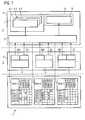
- FIG. 1shows a process plant 1, for example for carrying out chemical or pharmaceutical processes or for processes in the oil / gas industry, the woodworking industry, the paper industry or the like.
- a process plantbasically has a process control level 2 and a process level 3, the actual automation processes being based on the latter, which are characteristic of the type and use of the process plant.
- process control level 2and a process level 3
- process level 3the actual automation processes being based on the latter, which are characteristic of the type and use of the process plant.
- the process installation 1has an alarm system 5, which initially has an alarm processing system 6, which is preferably designed as a software in a data processing device not explicitly shown.
- the alarm processing system 6is operatively connected to an alarm indicator 7, which in turn has a number of alarm indicators / alarm generators 8.1 to 8.3 which are for example, visual / visual alarm indications such as lights or windows, or audible alarms such as horns or sirens.
- the alarm processing system 6is in operative connection with a memory device 9, which in the present case is designed to store an archive file 10 in the form of a so-called alarm journal.
- the process installation 1has as components of the automation process 4 a series of subprocesses A, B, C, which can each be identified with specific subprocesses or subprocesses of the automation process 4.
- Each of the three processes A to Ccomprises a number of process-related operations not explicitly shown, to which monitoring devices in the form of pressure, temperature sensors or the like are regularly assigned in a process plant of the type shown in FIG. 1, which monitor process states of the respective subprocess A to C.
- monitoring devicesare regularly associated with a number of process level alarms configured to generate a number of alarm information for indicating improper operations of the process plant or the respective (sub-) process, e.g. B. when a measured pressure drops sharply.
- each of the subprocesses A to C shown in FIG. 1 or the alarm transmitters provided in the context of the relevant subprocesscan also be referred to as an alarm group, whose specific embodiment in the case of the present invention will be discussed in more detail below with reference to FIG ,
- Each of the subprocesses A to C or the corresponding alarm groupinteracts with a message module or message module MA to MC and with a state module or state module ZA to ZC.
- the message blocks MA to MC and the state blocks ZA to ZCare in turn each with the alarm processing system 6 of the alarm system 5 in signaling connection.
- the alarm processing system 6includes a number of configuration matrices, matrix A, matrix B, matrix C. Each of the matrices is assigned to one of the subprocesses A to C or the corresponding alarm group.
- the second dimension (rows) of the configuration matrices matrix A, matrix B, matrix Cis formed by the respective sum of the alarm information that can be generated for the corresponding subprocess A to C.
- each of the alarm information designated in FIG. 1 with alarm Ai, alarm Bi, alarm Cicorresponds to the alarm signal of an alarm transmitter from the respective alarm group assigned to the corresponding subprocess.
- each of the displayed alarmsis provided for indicating an improper operation of the process plant or a running on this sub-process.
- the configuration matrices matrix A, matrix B, matrix Ccontain as entries correlation values for correlating each process state state Ai, state Bi, state Ci with the corresponding sum of the alarm information Ai, alarm Bi, alarm Ci that can be generated for the respective subprocess A to C.
- the correlation valuesare shown in Figure 1 in the form of crosses "X" and empty (white) fields in the respective matrices.
- each matrix entryrelates to a pair formed from a process state and an alarm information. Accordingly, each of these pairs is a first value ("X") or a second value (white field) assigned as a correlation value.
- the matrices matrix A, matrix B, matrix Cserve, depending on a specific / determined process state of the process plant 1 or a corresponding subprocess A to C, those alarm information alarm Ai, alarm Bi, alarm Ci generated in the course of this subprocess Display, d. H. to hide the first value ("X") as the correlation value.
- the "X" entries in the matrices Matrix A, Matrix B, Matrix C in FIG. 1form a configuration of non-relevant process alarms depending on a process state and serve the alarm processing system 6 as a kind of mask for masking alarm information, thus are not brought to display by the alarm indicator 7.
- each sub-process A to C or the associated alarm groupincludes a number of alarms that generate corresponding alarm information or alarm signals alarm Ai, alarm Bi, alarm Ci in the event of improper operation within the sub-process concerned.
- the configuration matrices Matrix A, Matrix B, Matrix Care used to determine which hardware interrupts are not relevant in which state of a particular subprocess and therefore, although they are generated at process level 3, need not be displayed at process level 2, for example by a siren switched on or a warning is shown on a screen, as would be possible with the help of the alarm indicator 7.
- the alarm group of the respective sub-process A to Ccorresponding alarm information is generated in the event of improper operation operations and transmitted via the associated message block MA, MB, MC to the alarm processing system 6.
- the state modules ZA, ZB, ZCrespectively assigned to the subprocesses A to C determine the current operating state of the subprocess and also transmit this to the alarm processing system 6.
- the alarm processing systemthus always knows in which process state a particular subprocess located.
- the alarm processing system 6transmits all generated alarm information, ie all relevant and all non-relevant process alarms to the memory device 9 or the alarm journal 10 guided therein independently of a display of alarm information by means of the alarm display device 7, thus independently From the display of alarm information at any time a (subsequent) control of the system state is possible.
- the projecting of the relevance of an alarm for an operating person (operator) of the process plant according to the invention with respect to the process statestakes place in a simple and unambiguous manner via a matrix and, in particular, requires no programming or system knowledge. It is sufficient if the project engineer who has configured the plant with regard to the automation function has process knowledge.
- the illustrated grouping of all alarming functions of a sub-process to an alarm groupalso a plant-wide alarm processing is possible, which - as shown in Figure 1 - associated with an advantageous central data storage and persistence even in distributed systems.
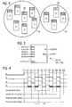
- FIG. 2shows a schematic representation of the copying of all alarming functions (also referred to herein as alarms) of a sub-process (cf., sub-processes A to C in FIG. 1) to an alarm group respectively assigned to the sub-processes.
- the individual alarm groupsare represented in FIG. 2 by circle-like boundary lines and have the same reference symbols A ', B' as the corresponding sub-processes in FIG. 1.
- Each alarm group A ', B'contains a number of alarm generators FB01 to FB06 or FB07 to FB09, each labeled as belonging to a respective alarm group A ', B' are "A '" and "B'", respectively.
- the alarms FB01 to FB09generate alarm information for indicating improper operation of the process plant or of the subprocess associated with the respective alarm group, which are transmitted to the alarm processing system 6 by the associated message module MA to MC (FIG.
- each alarm group A ', B' in FIG. 2also has a state module SR1 or SR2, which is likewise identified as belonging to the respective alarm group A ', B'"A'","B'".
- the state blocks SR1, SR2which correspond to the state blocks ZA to ZC shown there, serve for determining a (current) state of the relevant subprocess of the process plant and transmit it in standardized form to the alarm processing system 6 (FIG. 1).
- the state blocks ZA to ZC or SR1, SR2can therefore also be referred to as state normalization blocks.
- FIG. 3schematically shows one of the state modules ZA to ZC or SR1, SR2 assigned to a sub-process of FIGS. 1 or 2.
- Information about the process state of a sub-processis made available to the state block in the form of Boolean input parameters, which are designated in FIG. 3 as STATE_XX.
- STATE_XXIn the course of the illustrated embodiment up to thirty-two input parameters can be specified in this way.
- the input parameters STATE_XXdefine (code) a specific process state, which is communicated to the state block by the control logic of a user program (not shown) for controlling the automation process 4 at process level 3 (FIG. 1).
- the state module according to FIG. 3converts the (coded) state thus defined into an integer value QSTATE over a value range from zero to thirty-two and transmits this in the form of a state signal representing the respective process state to the alarm processing system 6, as shown in FIG.
- the value QSTATE for the state signal QSTATEis zero, and at a further output QERR of the state block an error signal with a low logic level (0) is output, which indicates error-free operation of the state block (not the process plant).
- the value zerois again output as the state signal QSTATE and generates a high logic level error signal (1) at the output QERR.
- FIG. 4shows the behavior of a process installation according to the invention during operation (runtime behavior) on the basis of a time diagram. Shown is a number of signal curves S1 to S4 as a function of the time t. In this case, certain times of the passage of time for the purpose of simpler identification are still denoted by numbers and are referred to below according to this numbering with t1, t2, .... Furthermore, in FIG. 4 certain control commands for operating the process plant 1 (FIG. 1 or the alarm system 5 present there) are indicated in quotation marks, which are assigned via punctured connection lines to specific times or signal transitions of the signals S1 to S4 are.
- the signals S1 to S4are binary signals that can be switched between a high logic level (1) and a low logic level (0).
- the control command "Activate alarm hiding" specified in FIG. 4is generated as a function of the configuration matrices Matrix A, Matrix B, Matrix C (FIG. 1), which are used to hide frame information as a function of process states of the process plant. It effects a switching of the corresponding signal S1 from a low to a high logic level at the times t1 and t8. As long as the signal S1 is not switched back to the low logic level ("deactivate alarm hiding", times t5, t12), the alarm hiding mechanism proposed in the context of the present invention is active. This can be traced in FIG. 4 on the basis of the signal curves S2 to S4 regarding the occurrence of alarm information in different areas of the process plant.
- the signal curve S2illustrates the pending or the generation of at least one alarm or alarm information at process level 3 (FIG. 1), for example by the alarm group A 'belonging to subprocess A (FIG. 2).
- This alarmis generated according to Figure 4 between the times t2 and t3, t4 and t6, t7 and t9 and t10 and t11.
- Waveform S3indicates the presence of this alarm in the alarm processing system 6 ( Figure 1). Since, according to the invention, no fading-out and suppression of alarm information takes place at process level 3, signal curve S3 corresponds exactly to signal curve S2 already described, since each alarm generated at the process level in the form of corresponding alarm information is also sent to process control level 2, d. H. enters the alarm processing system 6.
- control commands "activate alarm (coming)” and “deactive alarm (going)”furthermore given in FIG. 4 correlate with times at which the alarm in question is activated due to an improper operating procedure or deactivated again when returning to a proper operating procedure.
- the alarm system 5( Figure 1) is able to detect when the process plant or a subsystem / subprocess changes their state, so that pending alarms that are no longer relevant in the new system state according to the configuration matrices are hidden. In contrast, hidden alarms that become relevant in the new system state can be displayed again.
- the alarm system 5( Figure 1) further provides the ability to display to an operator a list of all hidden alarms. Alternatively or additionally, a list of those alarms can be displayed that would have to be hidden if they were generated by the (sub-) process at the relevant time.
- a timer functioncan be provided in the alarm system 5 (FIG. 1), so that when switching to a new system state, certain alarms that are no longer relevant in this state were relevant in a previous state, followed up for a certain period, d. H. be displayed, with the invention hide such alarms only after the expiration of a timer present in the timer function.
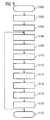
- FIG. 5shows a flow chart for illustrating an embodiment of the method according to the invention for operating a process plant, in particular the process plant 1 in FIG. 1.
- step S100a number of process states of the process plant are defined.
- a number of sub-processescan be defined in process step at step S102, wherein each sub-process is assigned a number of sub-process states and a number of generated alarm information in the form of an alarm group.
- each (partial) process stateis compared with the sum of the generatable, i. H. all of the alarm information that can be generated in connection with the relevant (sub-) process correlates, whereby each pair formed from a process state and an alarm information is assigned a first value or a second value as a correlation value.
- the correlation in step S104is preferably in the form of at least one configuration matrix, as has already been described in detail above.
- step S106a current operating state or partial operating state of the process plant is determined.
- step S108The particular state is transmitted to the alarm processing system at the process control level by a corresponding state device (step S108).
- step S110an error signal (see Figure 3) is also transmitted to the alarm processing system.
- step S112the alarm devices of at least one alarm group (FIG. 2) generate corresponding alarms or alarm information, which are likewise transmitted to the alarm processing system in step S114 by an associated signaling module (FIG. 1). This determines whether the proposed alarm hiding mechanism using the configuration matrices applies in accordance with the transmitted error signal in step S116.
- step S122ends in step S122.
- the methodcan return to step S106 following step S120, which is indicated by a dashed line in FIG. Accordingly, then in step S106, a re-determination of the current operating state of the process plant, whereupon the method is repeated corresponding to step S108.
- the inventionallows the detection of sub-process states for the purpose of assessing the relevance of alarms in combination with or based on the correlation between sub-station state and the sum of all subsystem alarms, this correlation being advantageously configured in the form of a matrix. In this way, a projecting of the alarm relevance in the process plant according to the invention without system and programming knowledge in a simple manner possible.
Landscapes
- Engineering & Computer Science (AREA)
- Physics & Mathematics (AREA)
- General Physics & Mathematics (AREA)
- Automation & Control Theory (AREA)
- General Engineering & Computer Science (AREA)
- Manufacturing & Machinery (AREA)
- Quality & Reliability (AREA)
- Human Computer Interaction (AREA)
- Testing And Monitoring For Control Systems (AREA)
Abstract
Description
Translated fromGermanDie vorliegende Erfindung betrifft ein Verfahren nach dem Oberbegriff des Patentanspruchs 1 zum Betreiben einer Prozessanlage, bei der auf Prozessebene eine Anzahl von Alarminformationen zum Anzeigen nicht ordnungsgemäßer Betriebsvorgänge der Prozessanlage generiert wird.The present invention relates to a method according to the preamble of
Weiterhin betrifft die vorliegende Erfindung eine Prozessanlage nach dem Oberbegriff des Patentanspruchs 10 mit einer Anzahl von Alarmgebern auf Prozessebene, die zum Generieren einer Anzahl von Alarminformationen zum Anzeigen nicht ordnungsgemäßer Betriebsvorgänge der Prozessanlage ausgebildet sind, und mit einer Alarmanzeigeeinrichtung zum Anzeigen von Alarminformationen. Darüber hinaus betrifft die vorliegende Erfindung ein Computerprogrammprodukt zum Betreiben einer Prozessanlage.Furthermore, the present invention relates to a process plant according to the preamble of
In der Leittechnik von Prozessanlagen, beispielsweise in der Chemieindustrie, der Pharmaindustrie oder der Öl-/Gasindustrie, werden regelmäßig Automatisierungssysteme eingesetzt, die im Falle nicht ordnungsgemäßer Betriebsvorgänge der Prozessanlage, wie Druckabfällen, Temperaturerhöhungen oder dergleichen, eine große Menge an Alarminformationen generieren und an einen Anlagenbediener (Operator) weiterleiten. Dies kann in bestimmten Situationen, beispielsweise beim Abschalten einer Prozessanlage, zu einer Flut systemgenerierter Alarme führen, die vom Operator nicht mehr beherrschbar bzw. überschaubar ist, woraus gegebenenfalls schwerwiegende Unfälle resultieren können.In the control technology of process equipment, for example in the chemical industry, the pharmaceutical industry or the oil / gas industry, automation systems are regularly used, which generate in case of improper operations of the process plant, such as pressure drops, temperature increases or the like, a large amount of alarm information and to a Forward plant operator (operator). In certain situations, for example when switching off a process plant, this can lead to a flood of system-generated alarms which are no longer manageable or manageable by the operator, which can possibly result in serious accidents.
Internationale Verbände, wie beispielsweise NAMUR (www.namur.de) verlangen daher in der Leittechnik von Prozessanlagen Lösungen, die in der Lage sind, in Abhängigkeit vom Anlagenzustand und der Kombination von anstehenden Alarmen bestimmte Alarme zu aktivieren bzw. zu deaktivieren (so genannte dynamische Alarmverarbeitung). Dies soll zu einer Reduktion des Alarmaufkommens führen und damit eine generelle Wiederherstellung der Anlagensicherheit ermöglichen.International associations such as NAMUR (www.namur.de) therefore demand solutions in the control technology of process plants that are capable of depending on the state of the plant and the combination of upcoming ones Alarms to activate or deactivate certain alarms (so-called dynamic alarm processing). This should lead to a reduction of the alarm volume and thus enable a general restoration of plant safety.
Aus dem Stand der Technik ist in diesem Zusammenhang die starre, d. h. nicht dynamische Filterung von Alarmen bekannt, bei der für jeden einzelnen generierbaren Alarm bestimmte Filterregeln explizit angegeben werden müssen. Prozessbedingte Alarmzustände (Teil-)Anlagenzustände werden vom System nicht erkannt oder dynamisch berücksichtigt.From the prior art in this context is the rigid, d. H. non-dynamic filtering of alarms, in which specific filter rules must be explicitly specified for each individual generated alarm. Process-related alarm states (partial) system states are not recognized by the system or taken into account dynamically.
Andere vorbekannte Lösungen ermöglichen die Filterung von Alarmen direkt an der Alarmquelle, d. h. auf Prozessebene, durch den Einbau einer entsprechenden Logik. Bei einer derartigen Lösung ist besonders als nachteilig anzusehen, dass eine Fehlerrückverfolgbarkeit nicht mehr gegeben ist. An der Quelle gefilterte Alarme können nicht archiviert werden und stehen somit nicht für spätere Analysen oder statistische Auswertungen auf Prozessleitebene zur Verfügung.Other prior art solutions allow the filtering of alarms directly at the alarm source, i. H. at the process level, by installing a corresponding logic. In such a solution is to be considered particularly disadvantageous that error traceability is no longer present. Source filtered alerts can not be archived and are therefore not available for later analysis or statistical analysis at the process control level.
Darüber hinaus sind so genannte Alarm-Management-Systeme in Form von designierten, unabhängigen Systemen für das Alarmhandling von Prozessanlagen bekannt. Da sie eigenständig und unabhängig vom Leitsystem der Prozessanlage arbeiten, erfordern sie entsprechende zusätzliche Aufmerksamkeit durch den Anlagenoperator. Des Weiteren bieten derartige unabhängige Systeme nicht den Komfort einer in den Anlagenbetrieb integrierten Lösung und sind darüber hinaus nicht in der Lage, Änderungen der Anlagenleittechnik automatisch zu berücksichtigen, da insbesondere eine getrennte Datenhaltung und ein getrenntes Engineering erfolgen.In addition, so-called alarm management systems in the form of designated, independent systems for alarm handling of process plants are known. Because they operate independently and independently of the control system of the process plant, they require corresponding additional attention by the plant operator. Furthermore, such independent systems do not offer the convenience of a solution integrated into the plant operation and, moreover, are not able to automatically take into account changes in the plant control technology, since separate data storage and separate engineering take place in particular.
Der Erfindung liegt die Aufgabe zugrunde, eine Prozessanlage und ein Verfahren zu deren Betrieb anzugeben, bei denen in einfacher Weise eine Reduktion des Alarmaufkommens in Abhängigkeit von Betriebszuständen der Anlage möglich ist, wobei eine vollständige Rückverfolgbarkeit von Alarminformationen möglich sein soll. Darüber hinaus soll trotz allem eine einfache Bedienbarkeit der Prozessanlage gegeben sein.The invention has for its object to provide a process plant and a method for their operation, in which a reduction of the alarm volume depending on operating conditions of the system is possible in a simple manner, whereby full traceability of alarm information should be possible. In addition, despite all, a simple operability of the process plant should be given.
Die Aufgabe wird bei einem Verfahren der eingangs genannten Art durch die kennzeichnenden Merkmale des Patentanspruchs 1 gelöst. Erfindungsgemäß ist ein Verfahren zum Betreiben einer Prozessanlage, bei der auf Prozessebene eine Anzahl von Alarminformationen zum Anzeigen nicht ordnungsgemäßer Betriebsvorgänge der Prozessanlage generiert wird, dadurch gekennzeichnet, dass
- a) eine Anzahl von Prozesszuständen der Prozessanlage definiert wird,
- b) jeder Prozesszustand mit der Summe der generierbaren Alarminformationen korreliert wird, wobei jedem aus einem Prozesszustand und einer Alarminformation gebildeten Paar ein erster Wert oder ein zweiter Wert als Korrelationswert zugewiesen wird,
- c) ein gegenwärtiger Betriebszustand der Prozessanlage bestimmt wird,
- d) in Abhängigkeit von dem bestimmten Prozesszustand diejenigen Alarminformationen nicht zur Anzeige gebracht werden, denen als Korrelationswert der erste Wert zugewiesen wurde.
- a) a number of process states of the process plant is defined,
- b) each process state is correlated with the sum of the generatable alarm information, wherein each pair formed from a process state and an alarm information is assigned a first value or a second value as a correlation value,
- c) a current operating state of the process plant is determined,
- d) depending on the particular process state, those alarm information items to which the first value has been assigned as the correlation value are not displayed.
Darüber hinaus wird die Aufgabe bei einer Prozessanlage der eingangs genannten Art durch die kennzeichnenden Merkmale des Patentanspruchs 10 gelöst.In addition, the problem is solved in a process plant of the type mentioned by the characterizing features of
Erfindungsgemäß ist eine Prozessanlage mit einer Anzahl von Alarmgebern auf Prozessebene, die zum Generieren einer Anzahl von Alarminformationen zum Anzeigen nicht ordnungsgemäßer Betriebsvorgänge der Prozessanlage ausgebildet sind, und mit einer Alarmanzeigeeinrichtung zum Anzeigen von Alarminformationen gekennzeichnet durch:
- mindestens einen einer Teilgruppe der Alarmgeber zugeordneten Zustandsbaustein, der zum Bestimmen wenigstens eines gegenwärtigen Prozesszustands der Prozessanlage aus einer Anzahl definierter Prozesszustände ausgebildet ist,
- ein Alarmverarbeitungssystem auf Prozessleitebene, das die generierten Alarminformationen und ein den bestimmten Prozesszustand repräsentierendes Zustandssignal empfängt und das zum Korrelieren jedes definierten Prozesszustands mit der Summe der empfangenen Alarminformationen ausgebildet ist, wobei jedem aus einem Prozesszustand und einer Alarminformation gebildeten Paar ein erster Wert oder ein zweiter Wert als Korrelationswert zuweisbar ist, wobei das Alarmverarbeitungssystem in Abhängigkeit von dem Zustandssignal zum Steuern der Alarmanzeigeeinrichtung zum Ausblenden derjenigen Alarminformationen ausgebildet ist, denen als Korrelationswert der erste Wert zugewiesen wurde.
- at least one state component assigned to a subgroup of the alarm generator and designed to determine at least one current process state of the process plant from a number of defined process states,
- a process control level alarm processing system that receives the generated alarm information and a state signal representing the determined process state and that is configured to correlate each defined process state with the sum of the received alarm information, wherein each pair formed from a process state and alarm information is a first value or a second value is assignable as a correlation value, wherein the alarm processing system is formed in response to the status signal for controlling the alarm display means for hiding those alarm information to which the first value has been assigned as a correlation value.
Die Aufgabe wird auch gelöst durch ein Computerprogrammprodukt zum Betreiben einer Prozessanlage, das Programmcodesequenzen aufweist, die bei Ausführung in einem Prozessleitsystem der Prozessanlage in Abhängigkeit von ermittelten Prozesszustandsdaten der Prozessanlage zum Verarbeiten von auf Prozessebene generierten Alarminformationen nach einem erfindungsgemäßen Verfahren ausgebildet sind.The object is also achieved by a computer program product for operating a process plant, which has program code sequences which, when executed in a process control system of the process plant, are designed according to determined process state data of the process plant for processing process level generated alarm information according to a method of the invention.
Vorteilhafte Ausgestaltungen der vorliegenden Erfindung sind Gegenstand von Unteransprüchen.Advantageous embodiments of the present invention are the subject of dependent claims.
Der vorgeschlagene Lösungsansatz integriert bisherige Alarmunterdrückungsmechanismen mit der Möglichkeit, die Relevanz von Alarminformationen in Form von Prozessalarmen dynamisch, d. h. anhand ermittelter Prozesszustände zu bestimmen und auf diese Weise nichtrelevante Prozessalarme auszublenden, d. h. nicht zur Anzeige zu bringen.The proposed solution integrates previous alarm suppression mechanisms with the possibility of determining the relevance of alarm information in the form of process alarms dynamically, ie on the basis of determined process states, and in this way suppressing non-relevant process alarms, ie not displaying them.
Zu diesem Zweck erfasst das Alarmverarbeitungssystem der Prozessanlage neben der Summe aller Prozessalarme auch die aktuellen Prozesszustände, um diese mit den Prozessalarmen zu korrelieren. Neben den auf Prozessebene generierten Prozessalarmen bzw. Alarminformationen werden also im Kontext der vorliegenden Erfindung auch Prozesszustände eines Automatisierungsprozesses bzw. einzelner Teilprozesse bei funktionaler Verteilung des Automatisierungsprozesses an das Alarmverarbeitungssystem übermittelt.For this purpose, in addition to the sum of all process alarms, the alarm processing system of the process plant also records the current process states in order to correlate these with the process alarms. In addition to the process alarms or alarm information generated at the process level, in the context of the present invention, process states of an automation process or of individual subprocesses in the case of functional distribution of the automation process are thus also transmitted to the alarm processing system.
Das Alarmverarbeitungssystem entscheidet aufgrund einer neuartigen paarweisen Korrelation aus jeweils einem Prozesszustand und einer Alarminformation in Verbindung mit einem jeweils zugeordneten Korrelationswert, welche Prozessalarme bei welchen Prozesszuständen angezeigt werden sollen und welche nicht. Nichtrelevante Alarme können auf diese Weise in Alarmanzeigen für den Operator ausgeblendet werden. Alternativ oder zusätzlich werden ausgeblendete Alarminformationen von akustischen und/oder optischen Signalgebern nicht berücksichtigt.The alarm processing system decides on the basis of a novel pairwise correlation of each one process state and an alarm information in conjunction with a respective associated correlation value, which process alarms should be displayed in which process states and which not. In this way, non-relevant alarms can be hidden in alarm displays for the operator. Alternatively or additionally, hidden alarm information from acoustic and / or visual signalers are not taken into account.
Da keine Unterdrückung von Alarminformationen an der Alarmquelle stattfindet, können zur Nachverfolgung insbesondere auch die ausgeblendeten Alarminformationen in einem Alarmjournal für eine spätere Nachvollziehbarkeit durch den Operator archiviert werden. Erfindungsgemäß ist somit die Gesamtfunktionalität des vorstehend skizzierten Alarmunterdrückungsmechanismus vollständig in ein vorhandenes Prozessleitsystem integrierbar.Since no suppression of alarm information takes place at the alarm source, in particular the hidden alarm information can be archived in an alarm journal for later traceability by the operator for tracing. Thus, according to the invention, the overall functionality of the above-outlined alarm suppression mechanism can be fully integrated into an existing process control system.
In Weiterbildung des erfindungsgemäßen Verfahrens ist vorgesehen, dass die Korrelation von Prozesszuständen und Alarminformationen in Form wenigstens einer Konfigurationsmatrix erfolgt, wobei eine erste Dimension der Konfigurationsmatrix durch die definierten Prozesszustände und eine zweite Dimension der Konfigurationsmatrix durch die generierbaren Alarminformationen gebildet wird, wobei die Korrelationswerte die Einträge der Konfigurationsmatrix darstellen.In a further development of the method according to the invention, it is provided that the correlation of process states and alarm information takes place in the form of at least one configuration matrix, wherein a first dimension of the configuration matrix is formed by the defined process states and a second dimension of the configuration matrix by the generated alarm information, the correlation values being the entries represent the configuration matrix.
Eine entsprechende Weiterbildung der erfindungsgemäßen Prozessanlage sieht vor, dass das Alarmverarbeitungssystem zum Korrelieren der Prozesszustände und der Alarminformationen wenigstens eine Konfigurationsmatrix aufweist, wobei eine erste Dimension der Konfigurationsmatrix durch die definierten Prozesszustände und eine zweite Dimension der Konfigurationsmatrix durch die generierbaren Alarminformationen gebildet sind, wobei die Korrelationswerte die Einträge der Konfigurationsmatrix darstellen.A corresponding refinement of the process installation according to the invention provides that the alarm processing system for correlating the process states and the alarm information has at least one configuration matrix, wherein a first dimension of the configuration matrix is formed by the defined process states and a second dimension of the configuration matrix by the generated alarm information, the correlation values represent the entries of the configuration matrix.
Auf diese Weise ist erfindungsgemäß in besonders einfacher Weise durch ein Vornehmen von Eintragungen in die Konfigurationsmatrix ein Projektieren der Alarmrelevanz ohne System- und/oder Programmierkenntnisse möglich.In this way, according to the invention, it is possible in a particularly simple manner to configure the alarm relevance without system and / or programming knowledge by making entries in the configuration matrix.
Aus Sicherheitsgründen ist es grundsätzlich erwünscht, alle generierten Alarminformationen zur Anzeige zu bringen, sofern nicht zustandsbedingte Gründe dagegensprechen, z. B. ist beim Abschalten einer Anlage das Ausblenden einer den erwarteten Druckabfall anzeigenden Alarminformation wünschenswert. Daher ist bei einer besonderen Ausführungsform der Erfindung vorgesehen, dass standardmäßig der zweite Wert (kein Ausblenden) als Korrelationswert zugewiesen wird.For security reasons, it is generally desirable to bring all generated alarm information to the display, unless state reasons speak against it, eg. B. when switching off a system fading a the expected pressure drop indicating alarm information is desirable. Therefore, it is provided in a particular embodiment of the invention that by default the second value (no fade-out) is assigned as a correlation value.
Um eine Rückverfolgbarkeit von Betriebszuständen der Prozessanlage zu gewährleisten, ist gemäß einer anderen Weiterbildung der Erfindung vorgesehen, dass in Abhängigkeit von dem bestimmten Prozesszustand zumindest diejenigen Alarminformationen, denen als Korrelationswert der erste Wert zugewiesen wurde, in einer Speichereinrichtung archiviert werden. Vorzugsweise werden jedoch alle generierten Alarminformationen unabhängig von ihrer gegenwärtigen Relevanz in der Speichereinrichtung archiviert.In order to ensure traceability of operating states of the process plant, it is provided according to another development of the invention that, depending on the particular process state, at least those alarm information to which the first value has been assigned as correlation value are archived in a memory device. Preferably, however, all generated alarm information is archived in the storage device regardless of its current relevance.
Zwecks einer vollständigen Integrierbarkeit der Erfindung in vorhandene Prozessanlagen ist in Weiterbildungen der Erfindung insbesondere vorgesehen, dass der Prozesszustand in Schritt c) des erfindungsgemäßen Verfahrens auf Prozessebene bestimmt und zusammen mit der Summe der generierten Alarminformationen zu einer Prozessleitebene der Prozessanlage übertragen wird und dass die Schritte b) und d) in einem Alarmverarbeitungssystem auf der Prozessleitebene durchgeführt werden.For the purpose of complete integration of the invention into existing process plants, it is provided in further developments of the invention in particular that the process state in step c) of the method according to the invention is at the process level determined and transmitted together with the sum of the generated alarm information to a process control level of the process plant and that the steps b) and d) are performed in an alarm processing system at the process control level.
Vorzugsweise wird bei einem Wechsel der Prozessanlage in einen neuen Prozesszustand im Zeitpunkt des Wechsels Schritt d) des erfindungsgemäßen Verfahrens erneut ausgeführt, wobei anstehende, bereits generierte Alarminformationen in Abhängigkeit von dem neuen Prozesszustand zur Anzeige gebracht werden.Preferably, when the process plant is changed to a new process state at the time of the change, step d) of the method according to the invention is carried out again, pending, already generated alarm information being displayed as a function of the new process state.
Auf diese Weise ist eine vollständig dynamische Alarmunterdrückung möglich.In this way, a fully dynamic alarm suppression is possible.
In Weiterbildung des erfindungsgemäßen Verfahrens ist noch vorgesehen, dass bei fehlerhafter Bestimmung des Prozesszustands in Schritt c) im nachfolgenden Schritt d) auch alle weiteren generierten Alarminformationen zur Anzeige gebracht werden.In a further development of the method according to the invention, it is also provided that, if the process state is determined incorrectly in step c), all further generated alarm information is also displayed in the following step d).
Auf diese Weise ist zum Erreichen einer erhöhten Anlagensicherheit gewährleistet, dass bei fehlerhaftem Arbeiten der erfindungsgemäßen Alarmunterdrückung keine generierten Alarminformationen verloren gehen.In this way, in order to achieve increased plant safety, it is ensured that no generated alarm information is lost if the alarm suppression according to the invention works incorrectly.
Wenn ein von der erfindungsgemäßen Anlage durchgeführter Automatisierungsprozess funktional in mehrere Teilprozesse aufgeteilt ist, sieht eine Weiterbildung der Erfindung vor, dass jedem Teilprozess eine Anzahl von Teilprozesszuständen und eine Anzahl von generierbaren Alarminformationen in Form einer Alarmgruppe zugeordnet werden und dass die Schritte b) bis d) des erfindungsgemäßen Verfahrens für jeden Teilprozess separat ausgeführt werden.If an automation process carried out by the installation according to the invention is functionally divided into several subprocesses, a development of the invention provides that each subprocess is assigned a number of subprocess states and a number of generated alarm information in the form of an alarm group and that steps b) to d) of the method according to the invention are carried out separately for each sub-process.
Weitere Eigenschaften und Vorteile der vorliegenden Erfindung ergeben sich aus der nachfolgenden Beschreibung von Ausführungsbeispielen anhand der Zeichnung.Further features and advantages of the present invention will become apparent from the following description of exemplary embodiments with reference to the drawing.
Es zeigt:
Figur 1- ein schematisches Blockschaltbild einer erfindungsgemäßen Prozessanlage,
Figur 2- eine schematische Darstellung einer Bildung von Alarmgruppen in der erfindungsgemäßen Prozessanlage gemäß
Figur 1, Figur 3- anhand einer detaillierten Darstellung einen Zustandsbaustein der Prozessanlage gemäß Figur 1,
Figur 4- ein Zeitablaufdiagramm des Alarmverhaltens einer nach einem erfindungsgemäßen Verfahren betriebenen Prozessanlage und
Figur 5- ein Flussdiagramm einer Ausgestaltung des erfindungsgemäßen Verfahrens.
- FIG. 1
- a schematic block diagram of a process plant according to the invention,
- FIG. 2
- 1 is a schematic representation of a formation of alarm groups in the process plant according to the invention according to FIG. 1,
- FIG. 3
- on the basis of a detailed representation of a state component of the process plant according to FIG. 1,
- FIG. 4
- a timing diagram of the alarm behavior of operated by a process according to the invention process plant and
- FIG. 5
- a flowchart of an embodiment of the method according to the invention.
Figur 1 zeigt eine Prozessanlage 1, beispielsweise zur Durchführung von chemischen oder pharmazeutischen Prozessen oder für Prozesse in der Öl-/Gasindustrie, der holzverarbeitenden Industrie, der Papierindustrie oder dergleichen. Eine derartige Anlage weist grundsätzlich eine Prozessleitebene 2 sowie eine Prozessebene 3 auf, wobei auf letzterer die eigentlichen Automatisierungsprozesse angesiedelt sind, die für Art und Einsatz der Prozessanlage charakteristisch sind. In Figur 1 ist exemplarisch ein derartiger Automatisierungsprozess dargestellt und mit Bezugszeichen 4 versehen.FIG. 1 shows a
Auf Prozessleitebene 2 besitzt die erfindungsgemäße Prozessanlage 1 ein Alarmsystem 5, das zunächst ein Alarmverarbeitungssystem 6 aufweist, welches vorzugsweise softwaretechnisch in einer nicht explizit dargestellten Datenverarbeitungseinrichtung ausgebildet ist. Das Alarmverarbeitungssystem 6 steht in Wirkverbindung mit einer Alarmanzeigeeinrichtung 7, die ihrerseits eine Anzahl von Alarmanzeigen/Alarmsignalgebern 8.1 bis 8.3 aufweist, bei denen es sich beispielsweise um visuelle/optische Alarmanzeigen, wie Lampen oder Bildschirmfenster, oder um akustische Alarmanzeigen, wie Hupen oder Sirenen, handeln kann. Darüber hinaus steht das Alarmverarbeitungssystem 6 in Wirkverbindung mit einer Speichereinrichtung 9, die vorliegend zum Speichern einer Archivdatei 10 in Form eines so genannten Alarmjournals ausgebildet ist.At
Auf Prozessebene 3 besitzt die erfindungsgemäße Prozessanlage 1 als Bestandteile des Automatisierungsprozesses 4 eine Reihe von Teilprozessen A, B, C, die jeweils mit bestimmten Teil- oder Unterprozessen des Automatisierungsprozesses 4 identifizierbar sind. Jeder der drei Prozesse A bis C umfasst eine Reihe von nicht explizit dargestellten prozesstechnischen Arbeitsvorgängen, denen bei einer Prozessanlage der in Figur 1 gezeigten Art regelmäßig Überwachungseinrichtungen in Form von Druck-, Temperatursensoren oder dergleichen zugeordnet sind, welche Prozesszustände des jeweiligen Teilprozesses A bis C überwachen. Darüber hinaus sind derartigen Überwachungseinrichtungen regelmäßig eine Anzahl von Alarmgebern auf Prozessebene zugeordnet, die zum Generieren einer Anzahl von Alarminformationen zum Anzeigen nicht ordnungsgemäßer Betriebsvorgänge der Prozessanlage bzw. des jeweiligen (Teil-)Prozesses ausgebildet sind, z. B. wenn ein gemessener Druck stark abfällt.At
In alarmtechnischer Hinsicht kann daher jeder der in Figur 1 dargestellten Teilprozesse A bis C bzw. die im Rahmen des betreffenden Teilprozesses vorgesehenen Alarmgeber auch als Alarmgruppe bezeichnet werden, auf deren konkrete Ausgestaltung im Falle der vorliegenden Erfindung weiter unten anhand der Figur 2 noch detailliert eingegangen wird.In terms of alarm technology, therefore, each of the subprocesses A to C shown in FIG. 1 or the alarm transmitters provided in the context of the relevant subprocess can also be referred to as an alarm group, whose specific embodiment in the case of the present invention will be discussed in more detail below with reference to FIG ,
Jeder der Teilprozesse A bis C bzw. die entsprechende Alarmgruppe wirkt mit einem Meldebaustein oder Meldemodul MA bis MC und mit einem Zustandsbaustein oder Zustandsmodul ZA bis ZC zusammen. Die Meldebausteine MA bis MC und die Zustandsbausteine ZA bis ZC stehen ihrerseits jeweils mit dem Alarmverarbeitungssystem 6 des Alarmsystems 5 in signaltechnischer Wirkverbindung.Each of the subprocesses A to C or the corresponding alarm group interacts with a message module or message module MA to MC and with a state module or state module ZA to ZC. The message blocks MA to MC and the state blocks ZA to ZC are in turn each with the
Wie aus Gründen der Übersichtlichkeit im unteren Teil der Figur 1 dargestellt ist, beinhaltet das Alarmverarbeitungssystem 6 eine Anzahl von Konfigurationsmatrizen Matrix A, Matrix B, Matrix C. Jede der Matrizen ist einem der Teilprozesse A bis C bzw. der entsprechenden Alarmgruppe zugeordnet. Eine erste Dimension (Spalten) der Konfigurationsmatrizen Matrix A, Matrix B, Matrix C wird durch vordefinierte Prozesszustände des entsprechenden Teilprozesses A bis C gebildet. Diese Prozesszustände sind in Figur 1 mit Zustand Ai, Zustand Bi, Zustand Ci bezeichnet, wobei i = 1, 2, ..., N. Dabei bezeichnet N eine maximale Anzahl möglicher Zustände pro Teilprozess, wobei N von Teilprozess zu Teilprozess variieren kann. Die zweite Dimension (Zeilen) der Konfigurationsmatrizen Matrix A, Matrix B, Matrix C ist durch die jeweilige Summe der für den entsprechenden Teilprozess A bis C generierbaren Alarminformationen gebildet. Dabei entspricht jede der in Figur 1 mit Alarm Ai, Alarm Bi, Alarm Ci bezeichneten Alarminformationen dem Alarmsignal eines Alarmgebers aus der dem entsprechenden Teilprozess jeweils zugeordneten Alarmgruppe. Dabei ist jeder der dargestellten Alarme zum Anzeigen eines nicht ordnungsgemäßen Betriebsvorgangs der Prozessanlage bzw. eines auf dieser ablaufenden Teilprozesses vorgesehen.As shown for clarity in the lower part of FIG. 1, the
Die Konfigurationsmatrizen Matrix A, Matrix B, Matrix C enthalten als Einträge Korrelationswerte zum Korrelieren jedes Prozesszustands Zustand Ai, Zustand Bi, Zustand Ci mit der entsprechenden Summe der für den jeweiligen Teilprozess A bis C generierbaren Alarminformationen Alarm Ai, Alarm Bi, Alarm Ci. Die Korrelationswerte sind in Figur 1 in Form von Kreuzen "X" bzw. leeren (weißen) Feldern in den entsprechenden Matrizen dargestellt. Dabei betrifft jeder Matrixeintrag ein aus einem Prozesszustand und einer Alarminformation gebildetes Paar. Entsprechend ist jedem dieser Paare ein erster Wert ("X") oder ein zweiter Wert (weißes Feld) als Korrelationswert zugewiesen.The configuration matrices matrix A, matrix B, matrix C contain as entries correlation values for correlating each process state state Ai, state Bi, state Ci with the corresponding sum of the alarm information Ai, alarm Bi, alarm Ci that can be generated for the respective subprocess A to C. The correlation values are shown in Figure 1 in the form of crosses "X" and empty (white) fields in the respective matrices. In this case, each matrix entry relates to a pair formed from a process state and an alarm information. Accordingly, each of these pairs is a first value ("X") or a second value (white field) assigned as a correlation value.
Die Matrizen Matrix A, Matrix B, Matrix C dienen erfindungsgemäß dazu, in Abhängigkeit von einem bestimmten/ermittelten Prozesszustand der Prozessanlage 1 bzw. eines entsprechenden Teilprozesses A bis C diejenigen im Rahmen dieses Teilprozesses generierten Alarminformationen Alarm Ai, Alarm Bi, Alarm Ci nicht zur Anzeige zu bringen, d. h. auszublenden, denen als Korrelationswert der erste Wert ("X") zugewiesen wurde. Mit anderen Worten: Die "X"-Einträge in den Matrizen Matrix A, Matrix B, Matrix C in Figur 1 bilden eine Konfiguration nichtrelevanter Prozessalarme in Abhängigkeit von einem Prozesszustand und dienen dem Alarmverarbeitungssystem 6 als eine Art Maske zum Ausblenden von Alarminformationen, die somit nicht zur Anzeige mittels der Alarmanzeigeeinrichtung 7 gebracht werden.According to the invention, the matrices matrix A, matrix B, matrix C serve, depending on a specific / determined process state of the
Der Betrieb der erfindungsgemäßen Prozessanlage 1 wird nachfolgend nochmals zusammenfassend erläutert:The operation of the
Für den Betrieb der Prozessanlage 1, d. h. zur Beschreibung der in den Teilprozessen A bis C ablaufenden Betriebsvorgänge werden eine Reihe von Zuständen Zustand Ai, Zustand Bi, Zustand Ci definiert, wie beispielsweise Anfahren, Normalbetrieb, Not-Aus, Herunterfahren oder dergleichen. Des Weiteren beinhaltet jeder Teilprozess A bis C bzw. die zugehörige Alarmgruppe eine Reihe von Alarmgebern, die bei einem Auftreten nicht ordnungsgemäßer Betriebsvorgänge innerhalb des betreffenden Teilprozesses entsprechende Alarminformationen oder Alarmsignale Alarm Ai, Alarm Bi, Alarm Ci erzeugen. Mit Hilfe der Konfigurationsmatrizen Matrix A, Matrix B, Matrix C wird festgelegt, welche Prozessalarme in welchem Zustand eines jeweiligen Teilprozesses nichtrelevant sind und daher, obgleich sie auf Prozessebene 3 generiert werden, auf Prozessleitebene 2 nicht zur Anzeige gebracht werden müssen, beispielsweise indem eine Sirene eingeschaltet oder ein Warnhinweis auf einem Bildschirm gezeigt wird, wie dies mit Hilfe der Alarmanzeigeeinrichtung 7 möglich wäre.For the operation of the
Mit anderen Worten: Durch die Alarmgruppe des betreffenden Teilprozesses A bis C werden im Falle nicht ordnungsgemäßer Betriebsvorgänge entsprechende Alarminformationen erzeugt und über den zugeordneten Meldebaustein MA, MB, MC an das Alarmverarbeitungssystem 6 übermittelt. Gleichzeitig bestimmen die den Teilprozessen A bis C jeweils zugeordneten Zustandsbausteine ZA, ZB, ZC (regelmäßig/kontinuierlich) den gegenwärtigen Betriebszustand des Teilprozesses und übermitteln diesen ebenfalls an das Alarmverarbeitungssystem 6. Das Alarmverarbeitungssystem hat somit jederzeit Kenntnis davon, in welchem Prozesszustand sich ein bestimmter Teilprozess befindet. Somit kann anhand der zugehörigen Konfigurationsmatrix Matrix A, Matrix B, Matrix C in Abhängigkeit von dem jeweiligen Prozesszustand des Teilprozesses bestimmt werden, welche der (anstehenden) Prozessalarme Ai, Bi, Ci in dem gegenwärtigen Zustand des Teilprozesses relevant sind (weißes Feld in der Matrix) und welche nicht ("X"). Dabei erfolgt das so genannte Alarm-Hiding (Ausblenden anstehender Alarminformationen) ausschließlich auf Prozessleitebene durch das Alarmverarbeitungssystem 6, an dem weiterhin alle durch die Alarmgruppen erzeugten Alarminformationen anliegen. Das Alarmverarbeitungssystem 6 entscheidet anschließend anhand der Konfigurationsmatrizen, welche Alarminformationen über die Alarmanzeigeeinrichtung 7 zur Anzeige gebracht werden und welche nicht.In other words, by the alarm group of the respective sub-process A to C corresponding alarm information is generated in the event of improper operation operations and transmitted via the associated message block MA, MB, MC to the
Bei der in Figur 1 gezeigten Ausgestaltung der erfindungsgemäßen Prozessanlage 1 übermittelt das Alarmverarbeitungssystem 6 unabhängig von einer Anzeige von Alarminformationen mittels der Alarmanzeigeeinrichtung 7 alle generierten Alarminformationen, d. h. alle relevanten und alle nichtrelevanten Prozessalarme an die Speichereinrichtung 9 bzw. das darin geführte Alarmjournal 10, sodass unabhängig von der Anzeige der Alarminformationen jederzeit eine (nachträgliche) Kontrolle des Anlagenzustands möglich ist.In the embodiment of the
In dieser Weise erfolgt erfindungsgemäß die Projektierung der Relevanz eines Alarms für eine Bedienperson (Operator) der erfindungsgemäßen Prozessanlage in Bezug auf die Prozesszustände in einfacher und eindeutiger Weise über eine Matrix und erfordert insbesondere keine Programmier- oder Systemkenntnisse. Es genügt, wenn der Projektierungsingenieur, der die Anlage bezüglich der Automatisierungsfunktion konfiguriert hat, Prozesskenntnisse hat. Durch die dargestellte Gruppierung aller alarmgebenden Funktionen eines Teilprozesses zu einer Alarmgruppe ist zudem eine anlagenweite Alarmverarbeitung möglich, die - wie in Figur 1 gezeigt - mit einer vorteilhaften zentralen Datenhaltung und -persistenz auch bei verteilten Systemen einhergeht.In this way, according to the invention, the projecting of the relevance of an alarm for an operating person (operator) of the process plant according to the invention with respect to the process states takes place in a simple and unambiguous manner via a matrix and, in particular, requires no programming or system knowledge. It is sufficient if the project engineer who has configured the plant with regard to the automation function has process knowledge. The illustrated grouping of all alarming functions of a sub-process to an alarm group also a plant-wide alarm processing is possible, which - as shown in Figure 1 - associated with an advantageous central data storage and persistence even in distributed systems.
Figur 2 zeigt anhand einer schematischen Darstellung die Kopierung aller alarmgebenden Funktionen (vorliegend auch als Alarmgeber bezeichnet) eines Teilprozesses (vgl. Teilprozesse A bis C in Figur 1) zu einer den Teilprozessen jeweils zugeordneten Alarmgruppe. Die einzelnen Alarmgruppen sind in Figur 2 durch kreisähnliche Umgrenzungslinien dargestellt und tragen ähnliche Bezugszeichen A', B', wie die entsprechenden Teilprozesse in Figur 1. Jede Alarmgruppe A', B' enthält eine Anzahl von Alarmgebern FB01 bis FB06 bzw. FB07 bis FB09, die jeweils als zu einer entsprechenden Alarmgruppe A', B' gehörig gekennzeichnet sind "A'" bzw. "B'". Wie bereits dargestellt wurde, erzeugen die Alarmgeber FB01 bis FB09 Alarminformationen zum Anzeigen nicht ordnungsgemäßer Betriebsvorgänge der Prozessanlage bzw. des der jeweiligen Alarmgruppe zugeordneten Teilprozesses, welche durch den zugehörigen Meldebaustein MA bis MC (Figur 1) an das Alarmverarbeitungssystem 6 übermittelt werden.2 shows a schematic representation of the copying of all alarming functions (also referred to herein as alarms) of a sub-process (cf., sub-processes A to C in FIG. 1) to an alarm group respectively assigned to the sub-processes. The individual alarm groups are represented in FIG. 2 by circle-like boundary lines and have the same reference symbols A ', B' as the corresponding sub-processes in FIG. 1. Each alarm group A ', B' contains a number of alarm generators FB01 to FB06 or FB07 to FB09, each labeled as belonging to a respective alarm group A ', B' are "A '" and "B'", respectively. As already stated, the alarms FB01 to FB09 generate alarm information for indicating improper operation of the process plant or of the subprocess associated with the respective alarm group, which are transmitted to the
Zusätzlich weist jede Alarmgruppe A', B' in Figur 2 noch einen Zustandsbaustein SR1 bzw. SR2 auf, der ebenfalls als zu der jeweiligen Alarmgruppe A', B' gehörig gekennzeichnet ist "A'", "B'". Wie ebenfalls unter Bezugnahme auf Figur 1 dargestellt wurde, dienen die Zustandsbausteine SR1, SR2, die den dort gezeigten Zustandsbausteinen ZA bis ZC entsprechen, zum Bestimmen eines (gegenwärtigen) Zustands des betreffenden Teilprozesses der Prozessanlage und übermitteln diesen in normierter Form an das Alarmverarbeitungssystem 6 (Figur 1). Die Zustandsbausteine ZA bis ZC bzw. SR1, SR2 lassen sich daher auch als Zustandsnormierungsbausteine bezeichnen.In addition, each alarm group A ', B' in FIG. 2 also has a state module SR1 or SR2, which is likewise identified as belonging to the respective alarm group A ', B'"A'","B'". As was also illustrated with reference to FIG. 1, the state blocks SR1, SR2, which correspond to the state blocks ZA to ZC shown there, serve for determining a (current) state of the relevant subprocess of the process plant and transmit it in standardized form to the alarm processing system 6 (FIG. 1). The state blocks ZA to ZC or SR1, SR2 can therefore also be referred to as state normalization blocks.
Wie vorstehend bereits detailliert erläutert wurde, dienen diese Zustände erfindungsgemäß dazu, anhand der Konfigurationsmatrizen Matrix A, Matrix B, Matrix C (Figur 1) zu entscheiden, welche generierten Alarminformationen in Abhängigkeit von dem bestimmten Prozesszustand zur Anzeige gebracht werden sollen und welche nicht.As has already been explained in detail above, these states are used according to the invention to decide on the basis of the configuration matrices Matrix A, Matrix B, Matrix C (FIG. 1) which generated alarm information is to be displayed as a function of the specific process state and which is not.
Figur 3 zeigt schematisch einen der einem Teilprozess der Figuren 1 oder 2 zugeordneten Zustandsbausteine ZA bis ZC bzw. SR1, SR2. Informationen über den Prozesszustand eines Teilprozesses werden dem Zustandsbaustein in Form von Booleschen Eingangsparametern zur Verfügung gestellt, die in Figur 3 mit STATE_XX bezeichnet sind. Im Zuge des dargestellten Ausführungsbeispiels können auf diese Weise bis zu zweiunddreißig Eingangsparameter vorgegeben werden. Die Eingangsparameter STATE_XX definieren (codieren) einen bestimmten Prozesszustand, welcher dem Zustandsbaustein durch die Steuerlogik eines (nicht gezeigten) Anwenderprogramms zur Steuerung des Automatisierungsprozesses 4 auf Prozessebene 3 (Figur 1) mitgeteilt wird. Auf diese Weise sind bei dem gezeigten Ausführungsbeispiel der vorliegenden Erfindung bis zu zweiunddreißig unterschiedliche Prozesszustände der Prozessanlage bzw. der ausgeführten Teilprozesse A bis C (Figur 1) definierbar. Der Zustandsbaustein gemäß Figur 3 wandelt den so definierten (codierten) Zustand in einen ganzzahligen Wert QSTATE auf einem Wertebereich von null bis zweiunddreißig um und übermittelt diesen in Form eines den jeweiligen Prozesszustand repräsentierenden Zustandssignals an das Alarmverarbeitungssystem 6, wie in Figur 1 gezeigt.FIG. 3 schematically shows one of the state modules ZA to ZC or SR1, SR2 assigned to a sub-process of FIGS. 1 or 2. Information about the process state of a sub-process is made available to the state block in the form of Boolean input parameters, which are designated in FIG. 3 as STATE_XX. In the course of the illustrated embodiment up to thirty-two input parameters can be specified in this way. The input parameters STATE_XX define (code) a specific process state, which is communicated to the state block by the control logic of a user program (not shown) for controlling the
Wenn bei dem gezeigten Ausführungsbeispiel der Figur 3 keines der linearen Eingangssignale STATE_XX einen hohen Logikpegel (1) hat, ergibt sich für das Zustandssignal QSTATE der Wert Null, und an einem weiteren Ausgang QERR des Zustandsbausteins wird ein Fehlersignal mit niedrigem Logikpegel (0) ausgegeben, was einen fehlerfreien Betrieb des Zustandsbausteins (nicht der Prozessanlage) anzeigt. Für den Fall, dass mehr als eines der binären Eingangssignale STATE_XX einen hohen Logikpegel (1) besitzen, wird als Zustandssignal QSTATE wiederum der Wert Null ausgegeben und am Ausgang QERR ein Fehlersignal mit hohem Logikpegel (1) erzeugt.In the embodiment shown in FIG. 3, if none of the linear input signals STATE_XX has a high logic level (1), the value QSTATE for the state signal QSTATE is zero, and at a further output QERR of the state block an error signal with a low logic level (0) is output, which indicates error-free operation of the state block (not the process plant). In the event that more than one of the binary input signals STATE_XX have a high logic level (1), the value zero is again output as the state signal QSTATE and generates a high logic level error signal (1) at the output QERR.
Das Fehlersignal QERR wird ebenfalls an das Alarmverarbeitungssystem 6 in Figur 1 übertragen, obwohl dies dort nicht explizit dargestellt ist. Es dient einer übergeordneten Steuerung des erfindungsgemäßen Alarm-Hiding-Mechanismus, wobei die unter Bezugnahme auf Figur 1 detailliert erläuterten Konfigurationsmatrizen Matrix A, Matrix B, Matrix C zum Ausblenden, d. h. zum Nicht-Anzeigen von Alarminformationen nur dann verwendet werden, wenn QERR = 0, d. h., wenn durch einen betreffenden Zustandsbaustein ZA bis ZC; SR1, SR2 kein Fehler signalisiert wird. Im entgegengesetzten Fall wird die entsprechende zugeordnete Konfigurationsmatrix Matrix A, Matrix B, Matrix C nicht verwendet, sondern es werden zur Sicherheit alle anstehenden generierten Alarminformationen für den betreffenden Teilprozess angezeigt und parallel archiviert.The error signal QERR is also transmitted to the
Figur 4 zeigt anhand eines Zeitablaufdiagramms das Verhalten einer erfindungsgemäßen Prozessanlage im Betrieb (Runtime-Verhalten). Dargestellt ist eine Anzahl von Signalverläufen S1 bis S4 in Anhängigkeit von der Zeit t. Dabei sind bestimmte Zeitpunkte des Zeitablaufs zwecks einfacherer Identifizierbarkeit weiterhin mit Ziffern bezeichnet und werden nachfolgend entsprechend dieser Nummerierung mit t1, t2, ... bezeichnet. Des Weiteren sind in Figur 4 in Anführungszeichen bestimmte Steuerbefehle zum Betreiben der Prozessanlage 1 (Figur 1, bzw. des dort vorhandenen Alarmsystems 5) angegeben, die über punktierte Verbindungslinien bestimmten Zeitpunkten bzw. Signalübergängen der Signale S1 bis S4 zugeordnet sind. Bei den Signalen S1 bis S4 handelt es sich um binäre Signale, die zwischen einem hohen Logikpegel (1) und einem niedrigen Logikpegel (0) umschaltbar sind.FIG. 4 shows the behavior of a process installation according to the invention during operation (runtime behavior) on the basis of a time diagram. Shown is a number of signal curves S1 to S4 as a function of the time t. In this case, certain times of the passage of time for the purpose of simpler identification are still denoted by numbers and are referred to below according to this numbering with t1, t2, .... Furthermore, in FIG. 4 certain control commands for operating the process plant 1 (FIG. 1 or the
Der in Figur 4 angegebene Steuerbefehl "Activate alarm hiding" wird in Abhängigkeit der Konfigurationsmatrizen Matrix A, Matrix B, Matrix C (Figur 1), welche zum Ausblenden von Rahmeninformationen in Abhängigkeit von Prozesszuständen der Prozessanlage verwendet werden, erzeugt. Er bewirkt ein Umschalten des entsprechenden Signals S1 von einem niedrigen auf einen hohen Logikpegel zu den Zeitpunkten t1 und t8. Solange das Signal S1 nicht wieder auf den niedrigen Logikpegel zurückgeschaltet wird ("deactivate alarm hiding"; Zeitpunkte t5, t12) ist der im Rahmen der vorliegenden Erfindung vorgeschlagene Alarm-Hiding-Mechanismus aktiv. Dies lässt sich in Figur 4 anhand der Signalverläufe S2 bis S4 betreffend das Anstehen von Alarminformationen in unterschiedlichen Bereichen der Prozessanlage nachvollziehen.The control command "Activate alarm hiding" specified in FIG. 4 is generated as a function of the configuration matrices Matrix A, Matrix B, Matrix C (FIG. 1), which are used to hide frame information as a function of process states of the process plant. It effects a switching of the corresponding signal S1 from a low to a high logic level at the times t1 and t8. As long as the signal S1 is not switched back to the low logic level ("deactivate alarm hiding", times t5, t12), the alarm hiding mechanism proposed in the context of the present invention is active. This can be traced in FIG. 4 on the basis of the signal curves S2 to S4 regarding the occurrence of alarm information in different areas of the process plant.
Der Signalverlauf S2 veranschaulicht das Anstehen bzw. die Generierung von mindestens einem Alarm bzw. einer Alarminformation auf Prozessebene 3 (Figur 1), beispielsweise durch die zu Teilprozess A gehörige Alarmgruppe A' (Figur 2). Dieser Alarm wird gemäß Figur 4 zwischen den Zeitpunkten t2 und t3, t4 und t6, t7 und t9 sowie t10 und t11 erzeugt. Signalverlauf S3 zeigt das Anstehen dieses Alarms in dem Alarmverarbeitungssystem 6 (Figur 1) an. Da erfindungsgemäß kein Ausblenden und Unterdrücken von Alarminformationen auf Prozessebene 3 stattfindet, entspricht der Signalverlauf S3 genau dem bereits beschriebenen Signalverlauf S2, da jeder auf Prozessebene erzeugte Alarm in Form einer entsprechenden Alarminformation auch auf die Prozessleitebene 2, d. h. in das Alarmverarbeitungssystem 6 gelangt.The signal curve S2 illustrates the pending or the generation of at least one alarm or alarm information at process level 3 (FIG. 1), for example by the alarm group A 'belonging to subprocess A (FIG. 2). This alarm is generated according to Figure 4 between the times t2 and t3, t4 and t6, t7 and t9 and t10 and t11. Waveform S3 indicates the presence of this alarm in the alarm processing system 6 (Figure 1). Since, according to the invention, no fading-out and suppression of alarm information takes place at
Der Signalverlauf S4 zeigt an, wie das Alarmverarbeitungssystem 6 (Figur 1) unter Verwendung einer entsprechenden Konfigurationsmatrix mit den anstehenden Alarminformationen verfährt. Speziell gibt Signalverlauf S4 an, ob die Alarminformation gemäß Signalverlauf S2, S3 in der Alarmanzeigeeinrichtung 7 (Figur 1) zur Anzeige gebracht wird, was durch einen hohen Logikpegel (1) symbolisiert ist. Vorausgesetzt, in der zu verwendenden Konfigurationsmatrix ist für den betreffenden Alarm in Abhängigkeit von einem gegenwärtigen Prozesszustand ein entsprechender (erster) Korrelationswert ("X" in Figur 1) eingetragen, wird der anstehende Alarm gemäß Signalverlauf S4 bei der Anzeige unterdrückt, was in Figur 4 durch dickere waagerechte Balken symbolisiert ist, und gelangt nur in der Zeit von t5 bis t8 zur Anzeige, da während dieser Zeit der im Rahmen der vorliegenden Erfindung vorgeschlagene Alarm-Hiding-Mechanismus deaktiviert ist (S1 = 0).The waveform S4 indicates how the alarm processing system 6 (Figure 1) proceeds with the pending alarm information using a corresponding configuration matrix. Specifically, waveform S4 indicates whether the alarm information according to waveform S2, S3 in the alarm indicator 7 (Figure 1) is displayed, which is symbolized by a high logic level (1). Provided that in the configuration matrix to be used, a corresponding (first) correlation value ("X" in FIG. 1) is entered for the relevant alarm as a function of a current process state, the pending alarm is suppressed according to signal curve S4 in the display, which is shown in FIG is symbolized by thicker horizontal bars, and only appears in the time from t5 to t8, since during this time the alarm hiding mechanism proposed in the context of the present invention is deactivated (S1 = 0).
Die in Figur 4 weiterhin angegebenen Steuerbefehle "activate alarm (coming)" und "deactive alarm (going)" korrelieren mit Zeitpunkten, in denen der betreffende Alarm aufgrund eines nicht ordnungsgemäßen Betriebsvorgangs aktiviert bzw. bei Rückkehr in einen ordnungsgemäßen Betriebsvorgang wieder deaktiviert wird.The control commands "activate alarm (coming)" and "deactive alarm (going)" furthermore given in FIG. 4 correlate with times at which the alarm in question is activated due to an improper operating procedure or deactivated again when returning to a proper operating procedure.
Auf diese Weise ist das Alarmsystem 5 (Figur 1) in der Lage zu erkennen, wann die Prozessanlage bzw. eine Teilanlage/Teilprozess ihren Zustand ändert, sodass anstehende Alarme, die im neuen Anlagenzustand nach Maßgabe der Konfigurationsmatrizen nicht mehr relevant sind, ausgeblendet werden. Demgegenüber können ausgeblendete Alarme, die im neuen Anlagenzustand relevant werden, wieder eingeblendet werden.In this way, the alarm system 5 (Figure 1) is able to detect when the process plant or a subsystem / subprocess changes their state, so that pending alarms that are no longer relevant in the new system state according to the configuration matrices are hidden. In contrast, hidden alarms that become relevant in the new system state can be displayed again.
In vorteilhafter Weise bietet das Alarmsystem 5 (Figur 1) weiterhin die Möglichkeit, einer Bedienperson eine Liste aller ausgeblendeten Alarme anzuzeigen. Alternativ oder zusätzlich kann eine Liste jener Alarme angezeigt werden, die auszublenden wären, wenn sie zu dem betreffenden Zeitpunkt vom (Teil-)Prozess generiert würden.Advantageously, the alarm system 5 (Figure 1) further provides the ability to display to an operator a list of all hidden alarms. Alternatively or additionally, a list of those alarms can be displayed that would have to be hidden if they were generated by the (sub-) process at the relevant time.
Darüber hinaus kann im Rahmen der vorliegenden Erfindung in dem Alarmsystem 5 (Figur 1) eine Timer-Funktion vorgesehen sein, sodass beim Umschalten in einen neuen Anlagenzustand bestimmte Alarme, die in diesem Zustand nicht mehr relevant sind, jedoch in einem vorhergehenden Zustand relevant waren, noch über einen bestimmten Zeitraum weiterverfolgt, d. h. angezeigt werden, wobei das erfindungsgemäße Ausblenden derartiger Alarme erst nach Ablauf eines in der Timer-Funktion vorhandenen Timers erfolgt.Moreover, in the context of the present invention, a timer function can be provided in the alarm system 5 (FIG. 1), so that when switching to a new system state, certain alarms that are no longer relevant in this state were relevant in a previous state, followed up for a certain period, d. H. be displayed, with the invention hide such alarms only after the expiration of a timer present in the timer function.
Figur 5 zeigt ein Flussdiagramm zur Darstellung einer Ausgestaltung des erfindungsgemäßen Verfahrens zum Betreiben einer Prozessanlage, insbesondere der Prozessanlage 1 in Figur 1.FIG. 5 shows a flow chart for illustrating an embodiment of the method according to the invention for operating a process plant, in particular the
Das Verfahren beginnt im Schritt S100. In einem anschließenden Schritt S102 wird eine Anzahl von Prozesszuständen der Prozessanlage definiert. Insbesondere können dabei in Schritt S102 auf Prozessebene eine Anzahl von Teilprozessen definiert werden, wobei jedem Teilprozess eine Anzahl von Teilprozesszuständen und eine Anzahl von generierbaren Alarminformationen in Form einer Alarmgruppe zugeordnet werden.The process starts in step S100. In a subsequent step S102, a number of process states of the process plant are defined. In particular, a number of sub-processes can be defined in process step at step S102, wherein each sub-process is assigned a number of sub-process states and a number of generated alarm information in the form of an alarm group.
Anschließend wird in Schritt S104 jeder (Teil-)Prozesszustand mit der Summe der generierbaren, d. h. aller in Zusammenhang mit dem betreffenden (Teil-)Prozess generierbaren Alarminformationen korreliert, wobei jedem aus einem Prozesszustand und einer Alarminformation gebildeten Paar ein erster Wert oder ein zweiter Wert als Korrelationswert zugewiesen wird. Erfindungsgemäß erfolgt dabei die Korrelation in Schritt S104 vorzugsweise in Form wenigstens einer Konfigurationsmatrix, wie weiter oben bereits ausführlich dargestellt wurde.Subsequently, in step S104, each (partial) process state is compared with the sum of the generatable, i. H. all of the alarm information that can be generated in connection with the relevant (sub-) process correlates, whereby each pair formed from a process state and an alarm information is assigned a first value or a second value as a correlation value. According to the invention, the correlation in step S104 is preferably in the form of at least one configuration matrix, as has already been described in detail above.
Für die nachfolgende Beschreibung wird angenommen, dass der im Rahmen der vorliegenden Erfindung vorgeschlagene Alarm-Hiding-Mechanismus aktiviert ist (S1 = 1 in Figur 4).For the following description, it is assumed that the alarm hiding mechanism proposed in the context of the present invention is activated (S1 = 1 in FIG. 4).
In Schritt S106 wird ein gegenwärtiger Betriebszustand oder Teilbetriebszustand der Prozessanlage bestimmt.In step S106, a current operating state or partial operating state of the process plant is determined.
Der bestimmte Zustand wird durch einen entsprechenden Zustandsbaustein an das Alarmverarbeitungssystem auf Prozessleitebene übermittelt (Schritt S108). Praktisch zeitgleich wird im Schritt S110 auch ein Fehlersignal (vgl. Figur 3) an das Alarmverarbeitungssystem übermittelt. Im Falle eines nicht ordnungsgemäßen Betriebszustands erzeugen in Schritt S112 die Alarmgeber wenigstens einer Alarmgruppe (Figur 2) entsprechende Alarme bzw. Alarminformationen, die in Schritt S114 durch einen zugeordneten Meldebaustein (Figur 1) ebenfalls an das Alarmverarbeitungssystem übertragen werden. Dieses ermittelt in Schritt S116, ob nach Maßgabe des übermittelten Fehlersignals der vorgeschlagene Alarm-Hiding-Mechanismus unter Verwendung der Konfigurationsmatrizen Anwendung findet.The particular state is transmitted to the alarm processing system at the process control level by a corresponding state device (step S108). At the same time, in step S110, an error signal (see Figure 3) is also transmitted to the alarm processing system. In the event of an improper operating state, in step S112 the alarm devices of at least one alarm group (FIG. 2) generate corresponding alarms or alarm information, which are likewise transmitted to the alarm processing system in step S114 by an associated signaling module (FIG. 1). This determines whether the proposed alarm hiding mechanism using the configuration matrices applies in accordance with the transmitted error signal in step S116.
Vorliegend sei angenommen, dass dies der Fall ist; somit erfolgt beim anschließenden Schritt aus S118 ein Ausblenden bestimmter Alarminformationen aufgrund der in den Matrizen enthaltenen Korrelationswerte, wobei nicht ausgeblendete Alarminformationen über die Alarmanzeigeeinrichtung zur Anzeige kommen. Praktisch zeitgleich werden in Schritt S120 wenigstens die ausgeblendeten Alarminformationen, vorzugsweise jedoch alle generierten Alarminformationen in der Speichereinrichtung der Prozessanlage archiviert.In the present case, it is assumed that this is the case; Thus, in the subsequent step from S118, certain alarm information is faded out due to the correlation values contained in the matrices, with non-faded alarm information being displayed via the alarm indicator. At the same time, at least the hidden alarm information, but preferably all generated alarm information, are archived in the memory device of the process plant in step S120.
Das Verfahren endet in Schritt S122. Alternativ und in an sich praxisrelevanter Weise kann das Verfahren jedoch im Anschluss an Schritt S120 nach Schritt S106 zurückkehren, was in Figur 5 durch eine gestrichelte Linie angedeutet ist. Entsprechend erfolgt dann in Schritt S106 eine erneute Bestimmung des gegenwärtigen Betriebszustands der Prozessanlage, woraufhin sich das Verfahren beginnend mit Schritt S108 entsprechend wiederholt.The process ends in step S122. Alternatively, however, in a practically relevant manner, the method can return to step S106 following step S120, which is indicated by a dashed line in FIG. Accordingly, then in step S106, a re-determination of the current operating state of the process plant, whereupon the method is repeated corresponding to step S108.
Auf diese Weise erlaubt die Erfindung das Erkennen von Teilprozesszuständen zum Zweck der Beurteilung der Relevanz von Alarmen in Kombination mit bzw. basierend auf der Korrelation zwischen Teilanlagenzustand und der Summe aller Teilanlagenalarme, wobei diese Korrelation vorteilhafterweise in Form einer Matrix konfiguriert ist. Auf diese Weise ist eine Projektierung der Alarmrelevanz bei der erfindungsgemäßen Prozessanlage ohne System- und Programmierkenntnisse in einfacher Weise möglich.In this way, the invention allows the detection of sub-process states for the purpose of assessing the relevance of alarms in combination with or based on the correlation between sub-station state and the sum of all subsystem alarms, this correlation being advantageously configured in the form of a matrix. In this way, a projecting of the alarm relevance in the process plant according to the invention without system and programming knowledge in a simple manner possible.
Claims (12)
Translated fromGermandadurch gekennzeichnet, dass
characterized in that
Priority Applications (2)
| Application Number | Priority Date | Filing Date | Title |
|---|---|---|---|
| EP06009891AEP1855172A1 (en) | 2006-05-12 | 2006-05-12 | Method for alarm suppression in a plant |
| US11/803,377US7620464B2 (en) | 2006-05-12 | 2007-05-14 | Method for operating a process plant, process plant and computer program product |
Applications Claiming Priority (1)
| Application Number | Priority Date | Filing Date | Title |
|---|---|---|---|
| EP06009891AEP1855172A1 (en) | 2006-05-12 | 2006-05-12 | Method for alarm suppression in a plant |
Publications (1)
| Publication Number | Publication Date |
|---|---|
| EP1855172A1true EP1855172A1 (en) | 2007-11-14 |
Family
ID=37561355
Family Applications (1)
| Application Number | Title | Priority Date | Filing Date |
|---|---|---|---|
| EP06009891ACeasedEP1855172A1 (en) | 2006-05-12 | 2006-05-12 | Method for alarm suppression in a plant |
Country Status (2)
| Country | Link |
|---|---|
| US (1) | US7620464B2 (en) |
| EP (1) | EP1855172A1 (en) |
Cited By (4)
| Publication number | Priority date | Publication date | Assignee | Title |
|---|---|---|---|---|
| WO2010060572A1 (en) | 2008-11-25 | 2010-06-03 | Pilz Gmbh & Co. Kg | Safety control and method for controlling an automated system |
| WO2010060574A1 (en)* | 2008-11-25 | 2010-06-03 | Pilz Gmbh & Co. Kg | Safety controller and method for controlling an automated installation |
| CN113485267A (en)* | 2021-07-12 | 2021-10-08 | 湖南先登智能科技有限公司 | Automatic control system for nickel-based target production |
| EP4083731A1 (en) | 2021-04-27 | 2022-11-02 | Siemens Aktiengesellschaft | Alarm management in process installations |
Families Citing this family (13)
| Publication number | Priority date | Publication date | Assignee | Title |
|---|---|---|---|---|
| DE102008060005A1 (en)* | 2008-11-25 | 2010-06-10 | Pilz Gmbh & Co. Kg | A safety controller and method for controlling an automated plant having a plurality of plant hardware components |
| EP2216695B1 (en)* | 2009-02-09 | 2013-03-27 | Siemens Aktiengesellschaft | Method for operating an automation system, corresponding computer program and system or device working according to the method |
| US8676537B2 (en)* | 2009-08-07 | 2014-03-18 | Taiwan Semiconductor Manufacturing Company, Ltd. | Portable wireless sensor |
| US8712571B2 (en)* | 2009-08-07 | 2014-04-29 | Taiwan Semiconductor Manufacturing Company, Ltd. | Method and apparatus for wireless transmission of diagnostic information |
| CN104011750A (en)* | 2011-12-28 | 2014-08-27 | 西门子公司 | Process technical systems |
| US10096238B2 (en)* | 2012-10-19 | 2018-10-09 | General Electric Technology Gmbh | Multidimensional information graphical user interface for energy systems |
| DE102014000701A1 (en)* | 2014-01-23 | 2015-07-23 | Sig Technology Ag | Method for controlling a packaging machine and a packaging machine |
| CN113050570B (en)* | 2015-10-09 | 2024-01-02 | 费希尔-罗斯蒙特系统公司 | System and method for providing an interconnection user interface corresponding to safety logic of a process control system |
| TWI650705B (en)* | 2017-08-17 | 2019-02-11 | 凌華科技股份有限公司 | System module and method for constructing customized display screen of non-intrusive data capture system |
| TWI668540B (en)* | 2017-10-30 | 2019-08-11 | 台灣積體電路製造股份有限公司 | Condition monitoring method for manufacturing tool, semiconductor manufacturing system and condition monitoring method thereof |
| CN108388653B (en)* | 2018-03-01 | 2020-07-31 | 东方电子股份有限公司 | Method for identifying opening type of 10kV outgoing line switch of transformer substation |
| EP4111278B1 (en)* | 2020-02-24 | 2024-02-14 | ABB Schweiz AG | A computer-implemented method for determining an operational state of an industrial plant |
| CN113886197B (en)* | 2021-09-26 | 2023-04-07 | 广东信通通信有限公司 | Alarm suppression method, device, equipment and storage medium |
Citations (2)
| Publication number | Priority date | Publication date | Assignee | Title |
|---|---|---|---|---|
| US5325522A (en)* | 1986-10-15 | 1994-06-28 | United States Data Corporation | Apparatus and method for communicating between devices trough use of a real time data base |
| DE102004016929A1 (en)* | 2003-04-08 | 2004-11-25 | Fisher-Rosemount Systems, Inc., Austin | Selection logic block with blanking functions for operation and maintenance for a process control system |
Family Cites Families (8)
| Publication number | Priority date | Publication date | Assignee | Title |
|---|---|---|---|---|
| US4975865A (en)* | 1989-05-31 | 1990-12-04 | Mitech Corporation | Method and apparatus for real-time control |
| US5267277A (en)* | 1989-11-02 | 1993-11-30 | Combustion Engineering, Inc. | Indicator system for advanced nuclear plant control complex |
| US5631825A (en)* | 1993-09-29 | 1997-05-20 | Dow Benelux N.V. | Operator station for manufacturing process control system |
| US6492901B1 (en)* | 2000-05-10 | 2002-12-10 | Westinghouse Electric Company Llc | Alarm management system |
| US6813587B2 (en)* | 2001-06-22 | 2004-11-02 | Invensys Systems, Inc. | Remotely monitoring/diagnosing distributed components of a supervisory process control and manufacturing information application from a central location |
| US7076312B2 (en)* | 2002-08-02 | 2006-07-11 | Fisher-Rosemount Systems, Inc. | Integrated electronic signatures for approval of process control and safety system software objects |
| DE10348563B4 (en)* | 2002-10-22 | 2014-01-09 | Fisher-Rosemount Systems, Inc. | Integration of graphic display elements, process modules and control modules in process plants |
| JP2007536634A (en)* | 2004-05-04 | 2007-12-13 | フィッシャー−ローズマウント・システムズ・インコーポレーテッド | Service-oriented architecture for process control systems |
- 2006
- 2006-05-12EPEP06009891Apatent/EP1855172A1/ennot_activeCeased
- 2007
- 2007-05-14USUS11/803,377patent/US7620464B2/enactiveActive
Patent Citations (2)
| Publication number | Priority date | Publication date | Assignee | Title |
|---|---|---|---|---|
| US5325522A (en)* | 1986-10-15 | 1994-06-28 | United States Data Corporation | Apparatus and method for communicating between devices trough use of a real time data base |
| DE102004016929A1 (en)* | 2003-04-08 | 2004-11-25 | Fisher-Rosemount Systems, Inc., Austin | Selection logic block with blanking functions for operation and maintenance for a process control system |
Non-Patent Citations (3)
| Title |
|---|
| BRAY M ET AL: "PRACTICAL ALARM FILTERING", INTECH, vol. 41, no. 2, February 1994 (1994-02-01), pages 34 - 36, XP009014395, ISSN: 0192-303X* |
| HENNINGSEN A ET AL: "Intelligent alarm handling in cement plants-lessons learned from the nuclear industry", CEMENT INDUSTRY TECHNICAL CONFERENCE, 1993. RECORD OF CONFERENCE PAPERS., 35TH IEEE TORONTO, ONT., CANADA 23-27 MAY 1993, NEW YORK, NY, USA,IEEE, US, 23 May 1993 (1993-05-23), pages 165 - 182, XP010111092, ISBN: 0-7803-0960-X* |
| LARSON, ÖHMAN, NIHLWING, JOKSTAD, KRISTIANSEN, KVALEM, LIND: "Alarm Reduction and Root Cause Analysis for Nuclear Power Plant Control Rooms", 2005, PROCEEDINGS OF THE ENLARGED HALDEN PROGRAMME GROUP MEETING, NORWAY, XP002413688* |
Cited By (7)
| Publication number | Priority date | Publication date | Assignee | Title |
|---|---|---|---|---|
| WO2010060572A1 (en) | 2008-11-25 | 2010-06-03 | Pilz Gmbh & Co. Kg | Safety control and method for controlling an automated system |
| WO2010060574A1 (en)* | 2008-11-25 | 2010-06-03 | Pilz Gmbh & Co. Kg | Safety controller and method for controlling an automated installation |
| US8560094B2 (en) | 2008-11-25 | 2013-10-15 | Pilz Gmbh & Co. Kg | Safety controller and method for controlling an automated installation |
| US8595827B2 (en) | 2008-11-25 | 2013-11-26 | Pilz Gmbh & Co. Kg | Safety controller and method for controlling an automated installation |
| EP4083731A1 (en) | 2021-04-27 | 2022-11-02 | Siemens Aktiengesellschaft | Alarm management in process installations |
| WO2022229105A1 (en) | 2021-04-27 | 2022-11-03 | Siemens Aktiengesellschaft | Alarm management in processing plants |
| CN113485267A (en)* | 2021-07-12 | 2021-10-08 | 湖南先登智能科技有限公司 | Automatic control system for nickel-based target production |
Also Published As
| Publication number | Publication date |
|---|---|
| US7620464B2 (en) | 2009-11-17 |
| US20080004723A1 (en) | 2008-01-03 |
Similar Documents
| Publication | Publication Date | Title |
|---|---|---|
| EP1855172A1 (en) | Method for alarm suppression in a plant | |
| EP1950639B1 (en) | Method for operating a process plant, process plant and computer program product | |
| DE60210448T2 (en) | IMPROVED HART DEVICE ALARM IN A PROCESS CONTROL SYSTEM | |
| DE10154534B4 (en) | Integrated alarm display in a process control network | |
| DE102004015617B4 (en) | Online device test block integrated into a process control / safety system | |
| DE102010037652B4 (en) | Method and apparatus for managing module run sequences in a process control environment | |
| DE10217107B4 (en) | Advanced device alarms in a process control system | |
| EP2356526B1 (en) | Safety control and method for controlling an automated system | |
| EP0893746B1 (en) | Process diagnosis system and method therefor | |
| EP2353052B1 (en) | Safety controller and method for controlling an automated installation | |
| DE102004016929B4 (en) | Control method and system for determining the presence of a shutdown condition within a process plant | |
| DE102010061132A1 (en) | Methods and Devices for Managing Process Control Status Rollups | |
| EP3451087B1 (en) | System and method for the selection and identification of field devices | |
| EP2356527B1 (en) | Safety control and method for controlling an automated system having a plurality of system hardware components | |
| EP3953774B1 (en) | Device for retreiving alarm causes | |
| EP1296207B1 (en) | HMI apparatus and method for operating a technical installation, automation system with HMI apparatus and computer program product with program for carrying out the method in a HMI apparatus or in an automation system | |
| EP2927819B1 (en) | Method for automatically processing a number of protocol files of an automation system | |
| DE3701714A1 (en) | METHOD AND DEVICE FOR MONITORING COMPUTER-CONTROLLED ACTUATORS | |
| DE10296915T5 (en) | Security Network System | |
| EP3622403A2 (en) | Method for the computer-aided, automated verification of requirements | |
| EP2188688B1 (en) | Method for monitoring a technical installation and monitoring system for carrying out said method | |
| DE60212376T2 (en) | SYSTEM FOR PROVIDABLE DIAGNOSIS IN A MEMORY PROGRAMMABLE CONTROL | |
| EP2928157B1 (en) | Method for analysing and/or evaluating of at least one event of a technical facility | |
| EP3454154A1 (en) | Automated detection of statistical dependencies between process messages | |
| EP4327168B1 (en) | Granular display of a loading state of web-based elements of a control system for a technical plant |
Legal Events
| Date | Code | Title | Description |
|---|---|---|---|
| PUAI | Public reference made under article 153(3) epc to a published international application that has entered the european phase | Free format text:ORIGINAL CODE: 0009012 | |
| AK | Designated contracting states | Kind code of ref document:A1 Designated state(s):AT BE BG CH CY CZ DE DK EE ES FI FR GB GR HU IE IS IT LI LT LU LV MC NL PL PT RO SE SI SK TR | |
| AX | Request for extension of the european patent | Extension state:AL BA HR MK YU | |
| 17P | Request for examination filed | Effective date:20071214 | |
| 17Q | First examination report despatched | Effective date:20080227 | |
| AKX | Designation fees paid | Designated state(s):DE FR GB IT | |
| STAA | Information on the status of an ep patent application or granted ep patent | Free format text:STATUS: THE APPLICATION HAS BEEN REFUSED | |
| 18R | Application refused | Effective date:20090615 |