EP1852033B1 - Electric depilator - Google Patents
Electric depilatorDownload PDFInfo
- Publication number
- EP1852033B1 EP1852033B1EP05706615AEP05706615AEP1852033B1EP 1852033 B1EP1852033 B1EP 1852033B1EP 05706615 AEP05706615 AEP 05706615AEP 05706615 AEP05706615 AEP 05706615AEP 1852033 B1EP1852033 B1EP 1852033B1
- Authority
- EP
- European Patent Office
- Prior art keywords
- pieces
- piece
- clipping
- whole set
- shaft
- Prior art date
- Legal status (The legal status is an assumption and is not a legal conclusion. Google has not performed a legal analysis and makes no representation as to the accuracy of the status listed.)
- Expired - Lifetime
Links
- 230000009467reductionEffects0.000claimsdescription10
- 210000004209hairAnatomy0.000description13
- 230000009471actionEffects0.000description6
- 230000000712assemblyEffects0.000description4
- 238000000429assemblyMethods0.000description4
- 208000002271trichotillomaniaDiseases0.000description4
- 238000000034methodMethods0.000description3
- 238000010276constructionMethods0.000description1
- 238000005516engineering processMethods0.000description1
- 238000004519manufacturing processMethods0.000description1
- 229910052751metalInorganic materials0.000description1
- 239000002184metalSubstances0.000description1
- 150000002739metalsChemical class0.000description1
- 230000008569processEffects0.000description1
Images


Classifications
- A—HUMAN NECESSITIES
- A45—HAND OR TRAVELLING ARTICLES
- A45D—HAIRDRESSING OR SHAVING EQUIPMENT; EQUIPMENT FOR COSMETICS OR COSMETIC TREATMENTS, e.g. FOR MANICURING OR PEDICURING
- A45D26/00—Hair-singeing apparatus; Apparatus for removing superfluous hair, e.g. tweezers
- A45D26/0023—Hair-singeing apparatus; Apparatus for removing superfluous hair, e.g. tweezers with rotating clamping elements
- A45D26/0028—Hair-singeing apparatus; Apparatus for removing superfluous hair, e.g. tweezers with rotating clamping elements with rotating discs or blades
Definitions
- the present inventionrelates to an electrical depilator, in particularly, to an electrical depilator which is easy in die sinking, convenient in assembling, and of low cost.
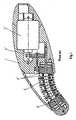
- Fig. 1shows a type of depilator among conventional ones.
- the depilatorcomprises a main body 1', a motor 2', a reduction gear set 3', an arcuate shaft 4', a set of base pieces 5' and thin clipping pieces 6'.
- Each clipping piece 6'is fixed on a corresponding base piece 5', that is, the thin clipping piece 6' is supported on and driven by the base piece 5' to move correspondingly.
- the whole set of base pieces 5'are coupled together by shifting yokes (not shown, or by bearing housings or shaft pins) so as to rotate synchronously.
- the whole set of base pieces 5' and the thin clipping pieces 6'are fitted over the arcuate shaft 4' which is supported on a shaft seat of the main body 1'.
- a first stage gear of the reduction gear set 3'meshes with a driving wheel of the motor 2', and a last stage gear is fixed on the base piece 5' which is located at the endmost position.
- the driving wheel of the motor 2'drives the whole set of base pieces 5' and the thin clipping pieces 6' supported on the base pieces 5' through the reduction gear set 3' to rotate around the arcuate shaft 4'.
- the clipping pieces 6' on the gradually-narrowed side of the arcuate shaft 4'are caused to perform a clipping action by the way of being pressed by the base pieces 5', and those on the gradually-widened side of the arcuate shaft 4' perform a loosening action.
- the depilatorcomprises a plurality of base pieces 5' performing pressure transfer and motion functions and thin clipping pieces 6' supported by the pieces 5' and performing a hair clipping function.
- the plurality of base pieces 5' and the clipping pieces 6'are arranged alternately in the following manner: one base piece 5' ⁇ two thin clipping pieces 6' ⁇ one base piece 5'...and so on.
- the cost of manufactureis high because the structure of the depilator is complicated and the thin clipping pieces 6' are generally made of metals.
- the assembling procedureis very troublesome because of the alternate arrangement in the form of one base piece 5' ⁇ two thin clipping pieces 6' ⁇ one base piece 5'... and so on.
- US Patent No. 5,976,157discloses a device for removing unwanted hair, including a housing and a hair-plucking assembly, rotably mounted to the housing, wherein the hair-plucking assembly comprises at least one disc assembly, wherein the disc assembly comprises an insert disc having at least one arm and two outer discs having at least one arm apiece, wherein the arms of the outer discs may be pressed against the arm of the insert disc to form two traps for hair.
- US Patent Application No. US 2001/0014809discloses a device for removing unwanted hair, including a hair-plucking assembly, a vibration assembly, a driving assembly, and a housing.
- the hair-plucking assemblyincludes at least two groups of disc assemblies that remove hairs as they rotate.
- disc assembliesare arranged in at least two rows, where disc assemblies arranged in one row rotate in an opposite direction to disc assemblies arranged in another row.
- the present inventionprovides an electrical depilator according to claim 1.
- the fixing membersmay be shifting yokes which are formed on both sides of each single-piece.
- One shifting yoke on a single-piecemay be inserted into and locked with another shifting yoke of an adjacent single-piece, thus the whole set of single-pieces are coupled together and rotated synchronously.
- the fixing membersmay be fork bodies which are provided with shaft holes at centers thereof corresponding to the position of the arcuate shaft.
- Each single-pieceis provided at both sides with fork shaped slots. Both sides of each fork body are inserted into and locked with two fork shaped slots of two adjacent single-pieces, thus the whole set of single-pieces are coupled together and rotated synchronously.
- the fixing membersmay be bearing housings.
- the whole set of single-piecesmay be coupled together by the bearing housings to be rotated synchronously.
- the fixing membersmay be shaft pins.
- the whole set of single-piecesmay be coupled together by the shaft pins to be rotated synchronously.
- the driving wheel of the motordrives the whole set of singe-pieces through the reduction gear set to rotate around the arcuate shaft.
- the single-pieces on the gradually-narrowed side of the arcuate shaftare caused to perform a clipping action, and those on the gradually-widened side of the arcuate shaft perform a loosening action.
- hairsare depilated quickly on the gradually-narrowed side of the arcuate shaft directly by use of the clipping surfaces of the singe-pieces, so as to depilate hairs quickly.
- the electrical depilator according to the present inventionhas the following advantages over the prior arts.
- the depilatoronly has a plurality of single-pieces. That is, the two types of pieces in the conventional art, i.e. the base pieces performing pressure transfer and motion functions and the thin clipping pieces supported by the pieces and performing a hair clipping function, are simplified as one type of single-pieces. As a result, the thin clipping pieces are eliminated. Thus, the number of members is reduced, which facilitates the die sinking because only the die for forming single-pieces is needed.
- the structureis greatly simplified and only the single-pieces are required to be assembled in assembling. Therefore, the assembling procedure is easy and the cost is reduced.
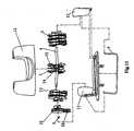
- an electrical depilatoraccording to one preferred embodiment of the present invention comprises a main body 1, a motor (not shown), a reduction gear set 3, an arcuate shaft 4 and a set of single-pieces 5.
- the arcuate shaft 4is supported on a shaft seat 11 of the main body 1.
- a first stage gear 31 of the reduction gear set 3meshes with the driving wheel (not shown) of the motor, and a last stage gear 32 is fixed on the single-piece 5 which is located at the endmost position.
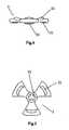
- Each single-piece 5has a clipping surface 51 and a supporting portion 52,as shown in Figs. 4-8 .
- the whole set of single-pieces 5are arranged in such a manner that the clipping surfaces 51 are opposite to each other.
- a clipping gap Ais formed between the opposite surfaces 51 of two single-pieces 5, as shown in Figs. 2 and 3 .
- the whole set of single-pieces 5are coupled together by fixing members so as to rotate synchronously.
- the fixing memberscan have a variety of specific structures. As shown in Figs. 4-8 of this embodiment, the fixing members are shifting yokes 53 which are formed on both sides of each single-piece 5.
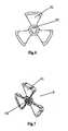
- the fixing memberscan also be fork bodies 54 shown in Fig. 14 which have three fork feet 542 respectively and are provided with shaft holes 541 at centers thereof corresponding to the inserting position of the arcuate shaft 4.
- each single-piece 5is provided at both sides thereof with fork shaped slots 501.
- each fork bodythat is, the three fork feet 542
- the fixing memberscan also be bearing housings which are not shown in drawings, by which the whole set of single-pieces 5 are coupled together and rotated synchronously.
- the fixing memberscan also be shaft pins which are not shown in drawings, by which the whole set of single-pieces 5 are coupled together and rotated synchronously. Referring to Figs 9 and 11 , the whole set of single-pieces 5 are fitted over the arcuate shaft 4 all together.
- the depilatorhas a good appearance, as shown in Fig. 10 .
- the driving wheel of the motordrives the whole set of singe-pieces 5 through the reduction gear set 3 to rotate around the arcuate shaft 4.
- the singe-pieces 5 on the gradually-narrowed side of the arcuate shaftare caused to perform a clipping action, and those on the gradually-widened side of the arcuate shaft perform a loosening action.
- hairsare depilated on the gradually-narrowed side of the arcuate shaft directly by use of the clipping surfaces of the singe-pieces 5 so as to depilate hairs quickly.
- Two types of pieces in the conventional arti.e.
- the base pieces 5' and the thin clipping pieces 6'are simplified as a type of single-pieces in the present invention, with the thin clipping pieces 6' being eliminated.
- the number of membersis reduced, which facilitates the die sinking because only the die for forming single-pieces 5 is needed.
- the structureis greatly simplified and only the single-pieces 5 are required to be assembled during the assembly process. Therefore, the assembly is easy and the cost is reduced.
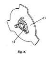
- a thin piece 55is fixed on each fork body 54 shown in Fig. 14 according to yet another embodiment of the present invention.
- the thin pieces 55 and the fork bodies 54, together with the whole set of single-pieces 5,are fitted over the arcuate shaft 4.
- the thin piece 55is provided between two opposite clipping surfaces 51 of two single-pieces 5, and two clipping gaps A are formed between both sides of each thin piece 55 and clipping surfaces 51 of two single-pieces 5, respectively. (That is, the gap A in Fig. 2 is divided into two parts.)
- two thin piecesare eliminated in this embodiment. Therefore, it is easy in die sinking, convenient in assembling, and of low cost.
- this embodimenthas twice the gaps with further introducing only one thin-piece 55. Thus, it has a better performance of depilating.
Landscapes
- Connection Of Motors, Electrical Generators, Mechanical Devices, And The Like (AREA)
- Dry Shavers And Clippers (AREA)
- Toys (AREA)
- Clamps And Clips (AREA)
- Gear Transmission (AREA)
- Chairs For Special Purposes, Such As Reclining Chairs (AREA)
Description
- The present invention relates to an electrical depilator, in particularly, to an electrical depilator which is easy in die sinking, convenient in assembling, and of low cost.
- There are various electrical depilators with different constructions in conventional technology and there are a great many patents relating to depilators.
Fig. 1 shows a type of depilator among conventional ones. The depilator comprises a main body 1', a motor 2', a reduction gear set 3', an arcuate shaft 4', a set of base pieces 5' and thin clipping pieces 6'. Each clipping piece 6' is fixed on a corresponding base piece 5', that is, the thin clipping piece 6' is supported on and driven by the base piece 5' to move correspondingly. The whole set of base pieces 5' are coupled together by shifting yokes (not shown, or by bearing housings or shaft pins) so as to rotate synchronously. The whole set of base pieces 5' and the thin clipping pieces 6' are fitted over the arcuate shaft 4' which is supported on a shaft seat of the main body 1'. A first stage gear of the reduction gear set 3' meshes with a driving wheel of the motor 2', and a last stage gear is fixed on the base piece 5' which is located at the endmost position.- When it is energized, the driving wheel of the motor 2' drives the whole set of base pieces 5' and the thin clipping pieces 6' supported on the base pieces 5' through the reduction gear set 3' to rotate around the arcuate shaft 4'. Thereby, the clipping pieces 6' on the gradually-narrowed side of the arcuate shaft 4' are caused to perform a clipping action by the way of being pressed by the base pieces 5', and those on the gradually-widened side of the arcuate shaft 4' perform a loosening action. Thus, hairs are depilated rapidly on the gradually-narrowed side of the arcuate shaft 4' by the clipping pieces 6', while the depilated hairs are thrown into the hair-collecting box on the gradually-widened side of the arcuate shaft 4'. Therefore, such depilator can depilate hairs rapidly.
- However, it can be readily appreciated that the above-mentioned depilator has the following disadvantages after a close study of its structure.
- The depilator comprises a plurality of base pieces 5' performing pressure transfer and motion functions and thin clipping pieces 6' supported by the pieces 5' and performing a hair clipping function. In addition, the plurality of base pieces 5' and the clipping pieces 6' are arranged alternately in the following manner: one base piece 5' → two thin clipping pieces 6' → one base piece 5'...and so on. Thus, there are too many members, which need die sinking not only for forming base piece 5' but also for forming thin clipping pieces 6'. Therefore, it is difficult in die sinking. Furthermore, the cost of manufacture is high because the structure of the depilator is complicated and the thin clipping pieces 6' are generally made of metals. Moreover, the assembling procedure is very troublesome because of the alternate arrangement in the form of one base piece 5' → two thin clipping pieces 6' → one base piece 5'... and so on.
US Patent No. 5,976,157 (YIU ) discloses a device for removing unwanted hair, including a housing and a hair-plucking assembly, rotably mounted to the housing, wherein the hair-plucking assembly comprises at least one disc assembly, wherein the disc assembly comprises an insert disc having at least one arm and two outer discs having at least one arm apiece, wherein the arms of the outer discs may be pressed against the arm of the insert disc to form two traps for hair.- US Patent Application No.
US 2001/0014809 discloses a device for removing unwanted hair, including a hair-plucking assembly, a vibration assembly, a driving assembly, and a housing. The hair-plucking assembly includes at least two groups of disc assemblies that remove hairs as they rotate. In an alternative embodiment, disc assemblies are arranged in at least two rows, where disc assemblies arranged in one row rotate in an opposite direction to disc assemblies arranged in another row. - In view of the above disadvantages in the conventional art, it is an object of the present invention to provide an electrical depilator which is easy in die sinking, convenient in assembling, and of low cost.
- In one aspect the present invention provides an electrical depilator according to claim 1.
- The fixing members may be shifting yokes which are formed on both sides of each single-piece. One shifting yoke on a single-piece may be inserted into and locked with another shifting yoke of an adjacent single-piece, thus the whole set of single-pieces are coupled together and rotated synchronously.
- The fixing members may be fork bodies which are provided with shaft holes at centers thereof corresponding to the position of the arcuate shaft. Each single-piece is provided at both sides with fork shaped slots. Both sides of each fork body are inserted into and locked with two fork shaped slots of two adjacent single-pieces, thus the whole set of single-pieces are coupled together and rotated synchronously.
- The fixing members may be bearing housings. The whole set of single-pieces may be coupled together by the bearing housings to be rotated synchronously.
- The fixing members may be shaft pins. The whole set of single-pieces may be coupled together by the shaft pins to be rotated synchronously.
- With the above structure, when energized, the driving wheel of the motor drives the whole set of singe-pieces through the reduction gear set to rotate around the arcuate shaft. Thereby, the single-pieces on the gradually-narrowed side of the arcuate shaft are caused to perform a clipping action, and those on the gradually-widened side of the arcuate shaft perform a loosening action. Thus, hairs are depilated quickly on the gradually-narrowed side of the arcuate shaft directly by use of the clipping surfaces of the singe-pieces, so as to depilate hairs quickly.
- The electrical depilator according to the present invention has the following advantages over the prior arts. The depilator only has a plurality of single-pieces. That is, the two types of pieces in the conventional art, i.e. the base pieces performing pressure transfer and motion functions and the thin clipping pieces supported by the pieces and performing a hair clipping function, are simplified as one type of single-pieces. As a result, the thin clipping pieces are eliminated. Thus, the number of members is reduced, which facilitates the die sinking because only the die for forming single-pieces is needed. In addition, the structure is greatly simplified and only the single-pieces are required to be assembled in assembling. Therefore, the assembling procedure is easy and the cost is reduced.
Fig. 1 is a schematic view showing the structure of a conventional electrical depilator;Fig. 2 is a view showing an appearance of the depilator according to one embodiment of the present invention;Fig. 3 is a partial exploded perspective view of the depilator according to one embodiment of the present invention;Fig. 4 is a side view of a single-piece according to one embodiment of the present invention;Fig. 5 is a top view of a single-piece according to one embodiment of the present invention;Fig. 6 is a bottom view of a single-piece according to one embodiment of the present invention;Fig. 7 is a perspective view of a single-piece according to one embodiment of the present invention;Fig. 8 is another perspective view of a single-piece according to one embodiment of the present invention;Fig. 9 is a perspective view of the whole set of single-pieces assembled on an arcuate shaft according to one embodiment of the present invention;Fig. 10 is a view partially showing the parts inFig. 3 being assembled;Fig. 11 is a partially exploded perspective view according to another embodiment of the present invention;Fig. 12 is a perspective view of a single-piece according to another embodiment of the present invention;Fig. 13 is another perspective view of a single-piece according to another embodiment of the present invention;Fig. 14 is a perspective view of a fork body according to another embodiment of the present invention;Fig. 15 is a partially exploded perspective view according to yet another embodiment of the present invention;Fig. 16 is a perspective view showing the fork body and the thin piece being assembled according to yet another embodiment of the present invention.- Embodiments of the present invention will be described in detail with reference to attached drawings.
- As shown in
Fig. 2 in conjunction withFig. 3 , an electrical depilator according to one preferred embodiment of the present invention comprises a main body 1, a motor (not shown), a reduction gear set 3, an arcuate shaft 4 and a set of single-pieces 5. - The arcuate shaft 4 is supported on a
shaft seat 11 of the main body 1. - A
first stage gear 31 of the reduction gear set 3 meshes with the driving wheel (not shown) of the motor, and alast stage gear 32 is fixed on the single-piece 5 which is located at the endmost position. - Each single-
piece 5 has a clippingsurface 51 and a supportingportion 52,as shown inFigs. 4-8 . The whole set of single-pieces 5 are arranged in such a manner that the clipping surfaces 51 are opposite to each other. A clipping gap A is formed between theopposite surfaces 51 of two single-pieces 5, as shown inFigs. 2 and3 . The whole set of single-pieces 5 are coupled together by fixing members so as to rotate synchronously. The fixing members can have a variety of specific structures. As shown inFigs. 4-8 of this embodiment, the fixing members are shiftingyokes 53 which are formed on both sides of each single-piece 5. One shiftingyoke 53 on each single-piece 5 is inserted into and locked with another shiftingyoke 53 on the adjacent single-piece 5, thus the whole set of single-pieces 5 are coupled together and rotated synchronously. In another embodiment, the fixing members can also befork bodies 54 shown inFig. 14 which have threefork feet 542 respectively and are provided withshaft holes 541 at centers thereof corresponding to the inserting position of the arcuate shaft 4. As shown in conjunction withFigs. 12 and 13 , each single-piece 5 is provided at both sides thereof with fork shapedslots 501. Both sides of each fork body (that is, the three fork feet 542) are inserted into and locked with two fork shapedslots 501 of two adjacent single-pieces 5, thus the whole set of single-pieces 5 are coupled together and rotated synchronously. The fixing members can also be bearing housings which are not shown in drawings, by which the whole set of single-pieces 5 are coupled together and rotated synchronously. The fixing members can also be shaft pins which are not shown in drawings, by which the whole set of single-pieces 5 are coupled together and rotated synchronously. Referring toFigs 9 and11 , the whole set of single-pieces 5 are fitted over the arcuate shaft 4 all together. - To facilitate the assembling of the single-
pieces 5 in the set, in the embodiment, firstly the whole set of single-pieces 5 are mounted on theshaft seat 11 by the arcuate shaft 4 and are fixed by aspring 6. Then the arcuate shaft 4, the reduction gear set 3 and theshaft seat 11 are covered by ashell 12, only the whole set of single-pieces 5 are exposed for depilating. Therefore, the depilator has a good appearance, as shown inFig. 10 . - With the above structure according to the present embodiment, when energized, the driving wheel of the motor drives the whole set of singe-
pieces 5 through the reduction gear set 3 to rotate around the arcuate shaft 4. Thereby, the singe-pieces 5 on the gradually-narrowed side of the arcuate shaft are caused to perform a clipping action, and those on the gradually-widened side of the arcuate shaft perform a loosening action. Thus, hairs are depilated on the gradually-narrowed side of the arcuate shaft directly by use of the clipping surfaces of the singe-pieces 5 so as to depilate hairs quickly. Two types of pieces in the conventional art, i.e. the base pieces 5' and the thin clipping pieces 6', are simplified as a type of single-pieces in the present invention, with the thin clipping pieces 6' being eliminated. Thus, the number of members is reduced, which facilitates the die sinking because only the die for forming single-pieces 5 is needed. In addition, the structure is greatly simplified and only the single-pieces 5 are required to be assembled during the assembly process. Therefore, the assembly is easy and the cost is reduced. - As shown in
Figs. 15-16 , athin piece 55 is fixed on eachfork body 54 shown inFig. 14 according to yet another embodiment of the present invention. Thethin pieces 55 and thefork bodies 54, together with the whole set of single-pieces 5, are fitted over the arcuate shaft 4. Thethin piece 55 is provided between two opposite clipping surfaces 51 of two single-pieces 5, and two clipping gaps A are formed between both sides of eachthin piece 55 and clipping surfaces 51 of two single-pieces 5, respectively. (That is, the gap A inFig. 2 is divided into two parts.) Compared with the conventional art, two thin pieces are eliminated in this embodiment. Therefore, it is easy in die sinking, convenient in assembling, and of low cost. In addition, compared with the above two embodiments, this embodiment has twice the gaps with further introducing only one thin-piece 55. Thus, it has a better performance of depilating.
Claims (5)
- An electrical depilator, comprising substantially a main body (1), a motor (2), a reduction gear set (3), an arcuate shaft (4) and a set of single-pieces (5), said arcuate shaft (4) being supported on a shaft seat (11) of the main body, a first stage gear (31) of said reduction gear set (3) being meshed with a driving wheel of said motor (2), a last stage gear (32) being fixed on the single-piece (5) which is located at the endmost position, each single-piece (5) having three arms, each of arms having a clipping surface (51) on one surface and a supporting portion (52) provided at the other surface of the arm opposite to the clipping surface, the whole set of single-pieces being arranged in such a manner that the clipping surfaces (51) are opposite to each other, a clipping gap being formed between opposite clipping surfaces (51) of two arms of two single-pieces (5), said whole set of single-pieces being coupled together by fixing members so as to rotate synchronously, and said whole set of single-pieces being fitted over the arcuate shaft all together.
- The electrical depilator according to claim 1, wherein:the fixing members are shifting yokes (53) which are formed on both sides of each single-piece (5), and one shifting yoke (53) on a single-piece (5) is inserted into and locked with another shifting yoke (53) on an adjacent single-piece (5) so that the whole set of single-pieces are coupled together and rotated synchronously.
- The electrical depilator according to claim 1, wherein:the fixing members are fork bodies (54) which are provided with shaft holes (541) at centers thereof corresponding to the position of the arcuate shaft (4), each single-piece (5) is provided at both sides with fork shaped slots (501), and both sides of each fork body (54) are inserted into and locked with two fork shaped slots (501) of two adjacent single-pieces (5), thereby the whole set of single-pieces are coupled together and rotated synchronously.
- The electrical depilator according to claim 1, wherein:the fixing members are bearing housings, and the whole set of single-pieces are coupled together by the bearing housings so as to rotate synchronously.
- The electrical depilator according to claim 1, wherein:the fixing members are shaft pins, and the whole set of single-pieces are coupled together by the shaft pins so as to rotate synchronously.
Applications Claiming Priority (1)
| Application Number | Priority Date | Filing Date | Title |
|---|---|---|---|
| PCT/CN2005/000178WO2006081709A1 (en) | 2005-02-06 | 2005-02-06 | Electric depilator |
Publications (3)
| Publication Number | Publication Date |
|---|---|
| EP1852033A1 EP1852033A1 (en) | 2007-11-07 |
| EP1852033A4 EP1852033A4 (en) | 2010-07-07 |
| EP1852033B1true EP1852033B1 (en) | 2012-12-05 |
Family
ID=36776933
Family Applications (1)
| Application Number | Title | Priority Date | Filing Date |
|---|---|---|---|
| EP05706615AExpired - LifetimeEP1852033B1 (en) | 2005-02-06 | 2005-02-06 | Electric depilator |
Country Status (9)
| Country | Link |
|---|---|
| US (1) | US7824418B2 (en) |
| EP (1) | EP1852033B1 (en) |
| JP (1) | JP4431610B2 (en) |
| CN (1) | CN100434012C (en) |
| BR (1) | BRPI0506691A (en) |
| CA (1) | CA2558750A1 (en) |
| ES (1) | ES2400489T3 (en) |
| TR (1) | TR200705459T1 (en) |
| WO (1) | WO2006081709A1 (en) |
Families Citing this family (9)
| Publication number | Priority date | Publication date | Assignee | Title |
|---|---|---|---|---|
| WO2008083531A1 (en)* | 2007-01-12 | 2008-07-17 | Tuming You | Depilating device with improved structure |
| CN201079113Y (en)* | 2007-07-03 | 2008-07-02 | 高永� | Dynamo-electric plucker |
| JP2015528362A (en)* | 2012-09-17 | 2015-09-28 | コーニンクレッカ フィリップス エヌ ヴェ | Epilation device with open configuration |
| US20150230580A1 (en)* | 2012-09-17 | 2015-08-20 | Koninklijke Philips N.V. | Epilating device |
| US9743738B2 (en)* | 2013-04-16 | 2017-08-29 | Braun Gmbh | Attachment for epilator and epilator |
| CN105747467B (en)* | 2016-04-20 | 2022-09-09 | 温州市日增电器有限公司 | Hair remover |
| CN106003161B (en)* | 2016-05-19 | 2018-05-04 | 泉州经济技术开发区盈瑞恒机电有限公司 | A kind of novel hand-held oxter shaving robot |
| CN106963460B (en)* | 2017-05-23 | 2023-07-21 | 深圳价之链跨境电商有限公司 | Skin cleaning device and application method thereof |
| EP3552513B1 (en) | 2018-04-12 | 2020-12-16 | Braun GmbH | Compact tweezer head for epilation |
Family Cites Families (51)
| Publication number | Priority date | Publication date | Assignee | Title |
|---|---|---|---|---|
| US853096A (en)* | 1906-06-16 | 1907-05-07 | Henry H Lewis | Depilatory instrument. |
| US1071978A (en)* | 1912-04-11 | 1913-09-02 | John E White | Device for removing hairs. |
| US2417530A (en)* | 1944-12-09 | 1947-03-18 | Weiser Tobiah | Electrical hair removing instrument |
| US2888927A (en)* | 1955-11-29 | 1959-06-02 | Fozard Ethel Marion | Method and apparatus for removal of superfluous hair |
| US2894512A (en)* | 1957-10-07 | 1959-07-14 | Tapper Robert | Epilation device |
| US3054405A (en)* | 1959-09-09 | 1962-09-18 | Tapper Robert | Electrical fepilator |
| US3088470A (en)* | 1960-10-27 | 1963-05-07 | Dean L Burdick Associates Inc | Device for applying creams and the like to the skin |
| CH466081A (en)* | 1966-11-02 | 1968-11-30 | Electrical Quality Products Es | Electric razor |
| US3673671A (en)* | 1969-11-14 | 1972-07-04 | Bowman Co P H | Method of fabricating wood trusses |
| US4174713A (en)* | 1976-03-26 | 1979-11-20 | Mehl Thomas L | Device for permanent removal of hair |
| CA1144990A (en)* | 1978-10-06 | 1983-04-19 | Robert H. Hahn | Depilatory tweezer |
| FR2639803B1 (en)* | 1988-12-07 | 1991-02-15 | Demeester Jacques | HAIR REMOVAL APPARATUS |
| AT391831B (en)* | 1989-02-10 | 1990-12-10 | Philips Nv | EPILATION APPARATUS |
| IL89290A (en)* | 1989-02-14 | 1992-08-18 | Dolev Moshe | Hair removal device |
| IL90433A (en)* | 1989-05-26 | 1993-04-04 | Yair Daar Moshav Galia And Shi | Depilatory device |
| IL93266A0 (en) | 1989-09-14 | 1990-11-29 | Crestmoore Ltd | Depilatory device |
| DE3930884A1 (en)* | 1989-09-15 | 1991-03-28 | Braun Ag | DEVICE FOR PLUCKING HAIR |
| JP2992356B2 (en)* | 1990-05-28 | 1999-12-20 | 松下電工株式会社 | Hair removal device |
| NL9002770A (en)* | 1990-12-17 | 1992-07-16 | Philips Nv | METHOD FOR EPILATING. |
| DE69229072T2 (en)* | 1991-02-20 | 1999-08-26 | Matsushita Electric Works | Depilatory device |
| US5163288A (en)* | 1991-03-05 | 1992-11-17 | Moshe Doley | Rotary head multi-spring hair removal device |
| US5100414A (en)* | 1991-03-05 | 1992-03-31 | Moshe Dolev | Rotary head multi-spring hair removal device |
| US5226907A (en)* | 1991-10-29 | 1993-07-13 | Tankovich Nikolai I | Hair removal device and method |
| US5425728A (en)* | 1991-10-29 | 1995-06-20 | Tankovich; Nicolai I. | Hair removal device and method |
| FR2686700A1 (en) | 1992-01-23 | 1993-07-30 | Rahban Thierry | ANALOG MULTIPLEXER PROTECTED AGAINST STRONG INPUT VOLTAGES. |
| US5196021A (en)* | 1992-02-25 | 1993-03-23 | Perfect Lady Ltd. | Depilatory device |
| US5230303A (en)* | 1992-06-12 | 1993-07-27 | Rubino Robert M | Pet hair removal apparatus |
| FR2699448A1 (en) | 1992-12-09 | 1994-06-24 | Carlier Jean | Local illumination appts. for skin surfaces operating during shaving or depilation |
| US5281233A (en)* | 1993-02-12 | 1994-01-25 | Moshe Dolev | Disc assembly hair remover |
| US5507753A (en)* | 1993-04-15 | 1996-04-16 | Matsushita Electric Works, Ltd. | Depilating device with skin guide stretcher |
| DE4320958A1 (en)* | 1993-06-24 | 1995-01-12 | Braun Ag | Body hair removal device |
| US5419344A (en)* | 1994-04-28 | 1995-05-30 | Thomas Lee DeWitt | Razor bump electrolysis |
| DE4427788C2 (en) | 1994-08-08 | 1999-11-25 | Braun Gmbh | Epilation device for removing hair from the human body |
| DE4428892A1 (en)* | 1994-08-18 | 1996-02-22 | Braun Ag | Epilation device with a multi-shell housing |
| US5595568A (en)* | 1995-02-01 | 1997-01-21 | The General Hospital Corporation | Permanent hair removal using optical pulses |
| DE19521585A1 (en)* | 1995-06-14 | 1996-12-19 | Braun Ag | Device for plucking hair from human skin |
| EP1044624B1 (en) | 1995-08-28 | 2003-12-10 | Matsushita Electric Works, Ltd. | Hand-held depilating device |
| US6165182A (en)* | 1995-11-28 | 2000-12-26 | U.S. Philips Corporation | Depilation apparatus with vibration member |
| FR2745992B1 (en)* | 1996-03-13 | 1998-08-28 | MECHANICAL PAIN REMOVAL DEVICE AND RELATED METHOD | |
| US5630811A (en)* | 1996-03-25 | 1997-05-20 | Miller; Iain D. | Method and apparatus for hair removal |
| US6067714A (en)* | 1997-10-03 | 2000-05-30 | Sharper Image Corporation | Turbo cleaning illuminated personal groomer |
| JP3840795B2 (en) | 1998-04-15 | 2006-11-01 | 松下電工株式会社 | Hair removal equipment |
| TW443921B (en)* | 1998-04-15 | 2001-07-01 | Matsushita Electric Works Ltd | Depilator |
| US6824546B1 (en)* | 1998-07-09 | 2004-11-30 | Soft Lines, Ltd. | Hair removal device with disc and vibration assemblies |
| US6123713A (en)* | 1998-07-09 | 2000-09-26 | K.I.S. Ltd | Hair removal device with vibrating assembly |
| US5976157A (en)* | 1998-07-09 | 1999-11-02 | K.I.S. Ltd. | Hair removal device with disc assembly |
| US6436106B2 (en) | 1998-07-09 | 2002-08-20 | Soft Lines, Ltd. | Hair removal device with disc, vibration, and light assemblies |
| JP3849345B2 (en)* | 1999-04-23 | 2006-11-22 | 松下電工株式会社 | Hair removal equipment |
| WO2002065871A1 (en)* | 2001-02-23 | 2002-08-29 | Koninklijke Philips Electronics N.V. | Hair removing device comprising a heating member |
| US6824461B1 (en)* | 2003-05-19 | 2004-11-30 | Moshe Dolev | Hair depilating device and method for improved depilating coverage |
| CN2722646Y (en)* | 2004-07-27 | 2005-09-07 | 刘莱生 | Electric hair picker |
- 2005
- 2005-02-06EPEP05706615Apatent/EP1852033B1/ennot_activeExpired - Lifetime
- 2005-02-06CNCNB2005800181203Apatent/CN100434012C/ennot_activeExpired - Fee Related
- 2005-02-06BRBRPI0506691-3Apatent/BRPI0506691A/ennot_activeIP Right Cessation
- 2005-02-06WOPCT/CN2005/000178patent/WO2006081709A1/enactiveApplication Filing
- 2005-02-06TRTR2007/05459Tpatent/TR200705459T1/enunknown
- 2005-02-06JPJP2007501097Apatent/JP4431610B2/ennot_activeExpired - Fee Related
- 2005-02-06ESES05706615Tpatent/ES2400489T3/ennot_activeExpired - Lifetime
- 2005-02-06USUS10/573,099patent/US7824418B2/ennot_activeExpired - Fee Related
- 2005-02-06CACA002558750Apatent/CA2558750A1/ennot_activeAbandoned
Also Published As
| Publication number | Publication date |
|---|---|
| CN1964645A (en) | 2007-05-16 |
| ES2400489T3 (en) | 2013-04-10 |
| EP1852033A1 (en) | 2007-11-07 |
| US20100292709A9 (en) | 2010-11-18 |
| WO2006081709A1 (en) | 2006-08-10 |
| US20080195118A1 (en) | 2008-08-14 |
| US7824418B2 (en) | 2010-11-02 |
| BRPI0506691A (en) | 2007-05-02 |
| TR200705459T1 (en) | 2008-01-21 |
| JP4431610B2 (en) | 2010-03-17 |
| EP1852033A4 (en) | 2010-07-07 |
| JP2007517639A (en) | 2007-07-05 |
| CN100434012C (en) | 2008-11-19 |
| CA2558750A1 (en) | 2006-08-10 |
Similar Documents
| Publication | Publication Date | Title |
|---|---|---|
| EP1852033B1 (en) | Electric depilator | |
| JP3542819B2 (en) | Gear device | |
| KR20020063487A (en) | A hand-held epilating device | |
| US20050187563A1 (en) | Hair removal device with disc and vibration assemblies | |
| EP1961328B1 (en) | Hair removal apparatus | |
| JP4584314B2 (en) | Epilation head and epilator | |
| JP2006175072A (en) | Depilation device | |
| JP2823316B2 (en) | Hair removal device | |
| US6473931B2 (en) | Painting roller assembly | |
| EP0460259A1 (en) | Rotary machine | |
| JP2001037533A (en) | Hair removing device | |
| JPH04126103A (en) | Depilating device | |
| JP4026564B2 (en) | Hair removal equipment | |
| JP7515926B2 (en) | Motor Actuator | |
| JP3873446B2 (en) | Hair removal equipment | |
| JP6820370B2 (en) | Electric skin treatment device and coupling unit for skin treatment device | |
| EP1067018A3 (en) | Steering column switch | |
| SU1723632A1 (en) | Electric machine and method of its assembly | |
| JP2003230251A (en) | Single axis actuator | |
| JP2004105639A (en) | Depilator | |
| JPH07336955A (en) | Motor brush box | |
| JPH04348704A (en) | Depilating device | |
| WO2002028219A1 (en) | Manual pocket device for hair-removal | |
| JP2000238531A (en) | Sun visor for vehicle with mirror | |
| JP2000125925A (en) | Depilator |
Legal Events
| Date | Code | Title | Description |
|---|---|---|---|
| PUAI | Public reference made under article 153(3) epc to a published international application that has entered the european phase | Free format text:ORIGINAL CODE: 0009012 | |
| 17P | Request for examination filed | Effective date:20060629 | |
| AK | Designated contracting states | Kind code of ref document:A1 Designated state(s):AT BE BG CH CY CZ DE DK EE ES FI FR GB GR HU IE IS IT LI LT LU MC NL PL PT RO SE SI SK TR | |
| DAX | Request for extension of the european patent (deleted) | ||
| A4 | Supplementary search report drawn up and despatched | Effective date:20100604 | |
| 17Q | First examination report despatched | Effective date:20111128 | |
| GRAP | Despatch of communication of intention to grant a patent | Free format text:ORIGINAL CODE: EPIDOSNIGR1 | |
| GRAS | Grant fee paid | Free format text:ORIGINAL CODE: EPIDOSNIGR3 | |
| GRAA | (expected) grant | Free format text:ORIGINAL CODE: 0009210 | |
| AK | Designated contracting states | Kind code of ref document:B1 Designated state(s):AT BE BG CH CY CZ DE DK EE ES FI FR GB GR HU IE IS IT LI LT LU MC NL PL PT RO SE SI SK TR | |
| REG | Reference to a national code | Ref country code:GB Ref legal event code:FG4D | |
| REG | Reference to a national code | Ref country code:CH Ref legal event code:EP | |
| REG | Reference to a national code | Ref country code:AT Ref legal event code:REF Ref document number:586786 Country of ref document:AT Kind code of ref document:T Effective date:20121215 | |
| REG | Reference to a national code | Ref country code:IE Ref legal event code:FG4D | |
| REG | Reference to a national code | Ref country code:DE Ref legal event code:R096 Ref document number:602005037270 Country of ref document:DE Effective date:20130131 | |
| REG | Reference to a national code | Ref country code:ES Ref legal event code:FG2A Ref document number:2400489 Country of ref document:ES Kind code of ref document:T3 Effective date:20130410 | |
| REG | Reference to a national code | Ref country code:AT Ref legal event code:MK05 Ref document number:586786 Country of ref document:AT Kind code of ref document:T Effective date:20121205 | |
| PG25 | Lapsed in a contracting state [announced via postgrant information from national office to epo] | Ref country code:LT Free format text:LAPSE BECAUSE OF FAILURE TO SUBMIT A TRANSLATION OF THE DESCRIPTION OR TO PAY THE FEE WITHIN THE PRESCRIBED TIME-LIMIT Effective date:20121205 Ref country code:FI Free format text:LAPSE BECAUSE OF FAILURE TO SUBMIT A TRANSLATION OF THE DESCRIPTION OR TO PAY THE FEE WITHIN THE PRESCRIBED TIME-LIMIT Effective date:20121205 Ref country code:SE Free format text:LAPSE BECAUSE OF FAILURE TO SUBMIT A TRANSLATION OF THE DESCRIPTION OR TO PAY THE FEE WITHIN THE PRESCRIBED TIME-LIMIT Effective date:20121205 | |
| REG | Reference to a national code | Ref country code:NL Ref legal event code:VDEP Effective date:20121205 | |
| REG | Reference to a national code | Ref country code:LT Ref legal event code:MG4D | |
| PG25 | Lapsed in a contracting state [announced via postgrant information from national office to epo] | Ref country code:GR Free format text:LAPSE BECAUSE OF FAILURE TO SUBMIT A TRANSLATION OF THE DESCRIPTION OR TO PAY THE FEE WITHIN THE PRESCRIBED TIME-LIMIT Effective date:20130306 Ref country code:SI Free format text:LAPSE BECAUSE OF FAILURE TO SUBMIT A TRANSLATION OF THE DESCRIPTION OR TO PAY THE FEE WITHIN THE PRESCRIBED TIME-LIMIT Effective date:20121205 Ref country code:PL Free format text:LAPSE BECAUSE OF FAILURE TO SUBMIT A TRANSLATION OF THE DESCRIPTION OR TO PAY THE FEE WITHIN THE PRESCRIBED TIME-LIMIT Effective date:20121205 | |
| PG25 | Lapsed in a contracting state [announced via postgrant information from national office to epo] | Ref country code:AT Free format text:LAPSE BECAUSE OF FAILURE TO SUBMIT A TRANSLATION OF THE DESCRIPTION OR TO PAY THE FEE WITHIN THE PRESCRIBED TIME-LIMIT Effective date:20121205 | |
| PG25 | Lapsed in a contracting state [announced via postgrant information from national office to epo] | Ref country code:BE Free format text:LAPSE BECAUSE OF FAILURE TO SUBMIT A TRANSLATION OF THE DESCRIPTION OR TO PAY THE FEE WITHIN THE PRESCRIBED TIME-LIMIT Effective date:20121205 Ref country code:IS Free format text:LAPSE BECAUSE OF FAILURE TO SUBMIT A TRANSLATION OF THE DESCRIPTION OR TO PAY THE FEE WITHIN THE PRESCRIBED TIME-LIMIT Effective date:20130405 Ref country code:BG Free format text:LAPSE BECAUSE OF FAILURE TO SUBMIT A TRANSLATION OF THE DESCRIPTION OR TO PAY THE FEE WITHIN THE PRESCRIBED TIME-LIMIT Effective date:20130305 Ref country code:EE Free format text:LAPSE BECAUSE OF FAILURE TO SUBMIT A TRANSLATION OF THE DESCRIPTION OR TO PAY THE FEE WITHIN THE PRESCRIBED TIME-LIMIT Effective date:20121205 Ref country code:CZ Free format text:LAPSE BECAUSE OF FAILURE TO SUBMIT A TRANSLATION OF THE DESCRIPTION OR TO PAY THE FEE WITHIN THE PRESCRIBED TIME-LIMIT Effective date:20121205 Ref country code:SK Free format text:LAPSE BECAUSE OF FAILURE TO SUBMIT A TRANSLATION OF THE DESCRIPTION OR TO PAY THE FEE WITHIN THE PRESCRIBED TIME-LIMIT Effective date:20121205 | |
| PG25 | Lapsed in a contracting state [announced via postgrant information from national office to epo] | Ref country code:PT Free format text:LAPSE BECAUSE OF FAILURE TO SUBMIT A TRANSLATION OF THE DESCRIPTION OR TO PAY THE FEE WITHIN THE PRESCRIBED TIME-LIMIT Effective date:20130405 Ref country code:NL Free format text:LAPSE BECAUSE OF FAILURE TO SUBMIT A TRANSLATION OF THE DESCRIPTION OR TO PAY THE FEE WITHIN THE PRESCRIBED TIME-LIMIT Effective date:20121205 Ref country code:RO Free format text:LAPSE BECAUSE OF FAILURE TO SUBMIT A TRANSLATION OF THE DESCRIPTION OR TO PAY THE FEE WITHIN THE PRESCRIBED TIME-LIMIT Effective date:20121205 | |
| PG25 | Lapsed in a contracting state [announced via postgrant information from national office to epo] | Ref country code:MC Free format text:LAPSE BECAUSE OF NON-PAYMENT OF DUE FEES Effective date:20130228 | |
| REG | Reference to a national code | Ref country code:CH Ref legal event code:PL | |
| PLBE | No opposition filed within time limit | Free format text:ORIGINAL CODE: 0009261 | |
| STAA | Information on the status of an ep patent application or granted ep patent | Free format text:STATUS: NO OPPOSITION FILED WITHIN TIME LIMIT | |
| PG25 | Lapsed in a contracting state [announced via postgrant information from national office to epo] | Ref country code:DK Free format text:LAPSE BECAUSE OF FAILURE TO SUBMIT A TRANSLATION OF THE DESCRIPTION OR TO PAY THE FEE WITHIN THE PRESCRIBED TIME-LIMIT Effective date:20121205 Ref country code:CH Free format text:LAPSE BECAUSE OF NON-PAYMENT OF DUE FEES Effective date:20130228 Ref country code:LI Free format text:LAPSE BECAUSE OF NON-PAYMENT OF DUE FEES Effective date:20130228 | |
| 26N | No opposition filed | Effective date:20130906 | |
| PG25 | Lapsed in a contracting state [announced via postgrant information from national office to epo] | Ref country code:CY Free format text:LAPSE BECAUSE OF FAILURE TO SUBMIT A TRANSLATION OF THE DESCRIPTION OR TO PAY THE FEE WITHIN THE PRESCRIBED TIME-LIMIT Effective date:20121205 | |
| REG | Reference to a national code | Ref country code:IE Ref legal event code:MM4A | |
| PG25 | Lapsed in a contracting state [announced via postgrant information from national office to epo] | Ref country code:IT Free format text:LAPSE BECAUSE OF FAILURE TO SUBMIT A TRANSLATION OF THE DESCRIPTION OR TO PAY THE FEE WITHIN THE PRESCRIBED TIME-LIMIT Effective date:20121205 | |
| REG | Reference to a national code | Ref country code:DE Ref legal event code:R097 Ref document number:602005037270 Country of ref document:DE Effective date:20130906 | |
| PG25 | Lapsed in a contracting state [announced via postgrant information from national office to epo] | Ref country code:IE Free format text:LAPSE BECAUSE OF NON-PAYMENT OF DUE FEES Effective date:20130206 | |
| REG | Reference to a national code | Ref country code:FR Ref legal event code:PLFP Year of fee payment:11 | |
| PGFP | Annual fee paid to national office [announced via postgrant information from national office to epo] | Ref country code:ES Payment date:20150212 Year of fee payment:11 Ref country code:DE Payment date:20150210 Year of fee payment:11 | |
| PGFP | Annual fee paid to national office [announced via postgrant information from national office to epo] | Ref country code:GB Payment date:20150211 Year of fee payment:11 Ref country code:FR Payment date:20150223 Year of fee payment:11 | |
| PG25 | Lapsed in a contracting state [announced via postgrant information from national office to epo] | Ref country code:TR Free format text:LAPSE BECAUSE OF FAILURE TO SUBMIT A TRANSLATION OF THE DESCRIPTION OR TO PAY THE FEE WITHIN THE PRESCRIBED TIME-LIMIT Effective date:20121205 | |
| PG25 | Lapsed in a contracting state [announced via postgrant information from national office to epo] | Ref country code:LU Free format text:LAPSE BECAUSE OF NON-PAYMENT OF DUE FEES Effective date:20130206 Ref country code:HU Free format text:LAPSE BECAUSE OF FAILURE TO SUBMIT A TRANSLATION OF THE DESCRIPTION OR TO PAY THE FEE WITHIN THE PRESCRIBED TIME-LIMIT; INVALID AB INITIO Effective date:20050206 | |
| REG | Reference to a national code | Ref country code:DE Ref legal event code:R119 Ref document number:602005037270 Country of ref document:DE | |
| GBPC | Gb: european patent ceased through non-payment of renewal fee | Effective date:20160206 | |
| REG | Reference to a national code | Ref country code:FR Ref legal event code:ST Effective date:20161028 | |
| PG25 | Lapsed in a contracting state [announced via postgrant information from national office to epo] | Ref country code:GB Free format text:LAPSE BECAUSE OF NON-PAYMENT OF DUE FEES Effective date:20160206 Ref country code:DE Free format text:LAPSE BECAUSE OF NON-PAYMENT OF DUE FEES Effective date:20160901 Ref country code:FR Free format text:LAPSE BECAUSE OF NON-PAYMENT OF DUE FEES Effective date:20160229 | |
| PG25 | Lapsed in a contracting state [announced via postgrant information from national office to epo] | Ref country code:ES Free format text:LAPSE BECAUSE OF NON-PAYMENT OF DUE FEES Effective date:20160207 |