EP1850013A2 - Ventilator assembly - Google Patents
Ventilator assemblyDownload PDFInfo
- Publication number
- EP1850013A2 EP1850013A2EP07006494AEP07006494AEP1850013A2EP 1850013 A2EP1850013 A2EP 1850013A2EP 07006494 AEP07006494 AEP 07006494AEP 07006494 AEP07006494 AEP 07006494AEP 1850013 A2EP1850013 A2EP 1850013A2
- Authority
- EP
- European Patent Office
- Prior art keywords
- fan
- volume flow
- arrangement
- arrangement according
- generated
- Prior art date
- Legal status (The legal status is an assumption and is not a legal conclusion. Google has not performed a legal analysis and makes no representation as to the accuracy of the status listed.)
- Granted
Links
- 238000012937correctionMethods0.000claimsdescription17
- 239000004065semiconductorSubstances0.000claimsdescription13
- 238000001514detection methodMethods0.000claimsdescription11
- 230000006870functionEffects0.000claimsdescription10
- 230000001419dependent effectEffects0.000claimsdescription6
- 238000000034methodMethods0.000claimsdescription4
- 238000003860storageMethods0.000claimsdescription4
- 230000000694effectsEffects0.000claims1
- 238000004519manufacturing processMethods0.000abstractdescription2
- 238000005259measurementMethods0.000description15
- 238000010586diagramMethods0.000description7
- 238000009423ventilationMethods0.000description4
- 230000000903blocking effectEffects0.000description2
- 239000003990capacitorSubstances0.000description2
- 238000011109contaminationMethods0.000description2
- 230000007423decreaseEffects0.000description2
- 238000012986modificationMethods0.000description2
- 230000004048modificationEffects0.000description2
- 238000013459approachMethods0.000description1
- 238000003287bathingMethods0.000description1
- 238000009530blood pressure measurementMethods0.000description1
- 238000013461designMethods0.000description1
- 238000011161developmentMethods0.000description1
- 230000018109developmental processEffects0.000description1
- 230000005484gravityEffects0.000description1
- 238000010438heat treatmentMethods0.000description1
- 238000009434installationMethods0.000description1
- 230000001681protective effectEffects0.000description1
Images


Classifications
- F—MECHANICAL ENGINEERING; LIGHTING; HEATING; WEAPONS; BLASTING
- F04—POSITIVE - DISPLACEMENT MACHINES FOR LIQUIDS; PUMPS FOR LIQUIDS OR ELASTIC FLUIDS
- F04D—NON-POSITIVE-DISPLACEMENT PUMPS
- F04D27/00—Control, e.g. regulation, of pumps, pumping installations or pumping systems specially adapted for elastic fluids
- F04D27/004—Control, e.g. regulation, of pumps, pumping installations or pumping systems specially adapted for elastic fluids by varying driving speed
- F—MECHANICAL ENGINEERING; LIGHTING; HEATING; WEAPONS; BLASTING
- F04—POSITIVE - DISPLACEMENT MACHINES FOR LIQUIDS; PUMPS FOR LIQUIDS OR ELASTIC FLUIDS
- F04D—NON-POSITIVE-DISPLACEMENT PUMPS
- F04D25/00—Pumping installations or systems
- F04D25/02—Units comprising pumps and their driving means
- F04D25/06—Units comprising pumps and their driving means the pump being electrically driven
- F04D25/0606—Units comprising pumps and their driving means the pump being electrically driven the electric motor being specially adapted for integration in the pump
- F04D25/0666—Units comprising pumps and their driving means the pump being electrically driven the electric motor being specially adapted for integration in the pump a sensor is integrated into the pump/motor design
- F—MECHANICAL ENGINEERING; LIGHTING; HEATING; WEAPONS; BLASTING
- F24—HEATING; RANGES; VENTILATING
- F24F—AIR-CONDITIONING; AIR-HUMIDIFICATION; VENTILATION; USE OF AIR CURRENTS FOR SCREENING
- F24F11/00—Control or safety arrangements
- F24F11/70—Control systems characterised by their outputs; Constructional details thereof
- F24F11/72—Control systems characterised by their outputs; Constructional details thereof for controlling the supply of treated air, e.g. its pressure
- F24F11/74—Control systems characterised by their outputs; Constructional details thereof for controlling the supply of treated air, e.g. its pressure for controlling air flow rate or air velocity
- F24F11/77—Control systems characterised by their outputs; Constructional details thereof for controlling the supply of treated air, e.g. its pressure for controlling air flow rate or air velocity by controlling the speed of ventilators
- Y—GENERAL TAGGING OF NEW TECHNOLOGICAL DEVELOPMENTS; GENERAL TAGGING OF CROSS-SECTIONAL TECHNOLOGIES SPANNING OVER SEVERAL SECTIONS OF THE IPC; TECHNICAL SUBJECTS COVERED BY FORMER USPC CROSS-REFERENCE ART COLLECTIONS [XRACs] AND DIGESTS
- Y02—TECHNOLOGIES OR APPLICATIONS FOR MITIGATION OR ADAPTATION AGAINST CLIMATE CHANGE
- Y02B—CLIMATE CHANGE MITIGATION TECHNOLOGIES RELATED TO BUILDINGS, e.g. HOUSING, HOUSE APPLIANCES OR RELATED END-USER APPLICATIONS
- Y02B30/00—Energy efficient heating, ventilation or air conditioning [HVAC]
- Y02B30/70—Efficient control or regulation technologies, e.g. for control of refrigerant flow, motor or heating
Definitions
- the inventionrelates to an arrangement with a fan, in particular with an axial fan for the ventilation of a low energy house.
- Low-energy housesare usually forced-ventilated.
- different air flow ratesare required to ventilate different rooms.
- a continuous air volume flowbetween 5 l / s and 10 l / s is desired.
- the air flow rateshould be e.g. be increased to 15 l / s to ensure adequate ventilation of the bathroom.
- fansare usually used with the appropriate power reserve. Such fans promote according to their characteristic fan characteristic at maximum backpressure the minimum air flow rate, and at lower back pressure a much larger air flow rate.
- the air volume flowis too high, a lot of heat will be lost and unnecessary noise will be produced because the fan is constantly operating at high speed.
- a preferred embodiment of the inventionis the subject of claim 9. This gives a very compact and inexpensive control circuit for the ECM.
- a preferred embodiment of the inventionis the subject of claim 16. This gives a simple and stable control loop for the ECM.
- the terms left, right, up and downrefer to the respective drawing figure, and may vary from one drawing figure to the next, depending on a particular orientation (portrait or landscape). Identical or equivalent parts are denoted by the same reference numerals in the various figures and usually described only once.
- FIG. 1shows a fan arrangement 100 with a fan 120, which has a fan wheel 122.
- the fan 120is assigned to its drive a controlled by a microcontroller (microprocessor) ⁇ C 130 ECM 110th
- the microcontroller 130has a temperature and offset compensation arrangement COMP 150, a volumetric flow control arrangement V-RGL 160, and a speed controller N-RGL 170.
- the ⁇ C 130On the input side, the ⁇ C 130 is connected to a detection device FLOW SENSOR 140 for detecting an air volume flow generated by the fan 120, which is indicated schematically by arrows 125, and to the ECM 110. On the output side, the ⁇ C 130 is connected to the ECM 110.
- assembly 150is exemplified as a single component. However, their functions can also be performed by different components, which are realized separately.
- the fan 120is driven by the ECM 110 with the fan 122 rotating and an air flow 125 toward generated to the detection device 140. This is detected by the detection device 140, which generates a volumetric flow measurement Vmess for this purpose.
- the generation of this measured value Vmessis carried out using a device suitable for this purpose, for example a thermal anemometer or a flap anemometer.
- a thermal anemometer or a flap anemometerAn exemplary thermal anemometer with semiconductor sensors will be described below with reference to FIG.
- An exemplary flap anemometer with magnetic sensorwill be described below with reference to FIG.
- the detection of the air volume flow 125 and the generation of the measured value Vmesscan be done in any suitable manner.
- any other anemometerinstead of the described anemometer, e.g. a thermal hot wire anemometer, a flap anemometer with potentiometer, or a windmill anemometer for measuring the air flow rate and generating the measured value Vmess.
- the measured value Vmess and the current temperature Tuare supplied to the temperature and offset compensation arrangement 150.
- Thisis designed to correct the measured value Vmess as a function of the current temperature Tu during startup of the fan 120 and to compensate for an offset occurring in the measured value Vmess by the detection device 140 during operation of the fan 120.
- the arrangement 150has a memory unit 152 in which correction values dependent on the current temperature Tu are stored for correcting the measured value Vmess. From this memory unit 152, the arrangement 150 determines when commissioning the fan 120 depending on a respective current temperature Tu a corresponding correction value, with which the measured value V meas is corrected.
- An example method for temperature compensation of the measured value Vmess when starting the fan 120is described in FIG. Exemplary correction values are described in FIG. 8.
- the arrangement 150determines at a given fan speed the offset of the measured value Vmess generated by the detection device 140 and corrects this as a function of the current temperature Tu.
- the corrected offsetis stored as a temperature-compensated offset and the actual volumetric flow measured value by an addition - Subjected or subtraction process for the purpose of offset compensation.
- An example method for offset compensation of the actual measured value during operation of the fan 120is described in FIG. 7.
- the temperature- and offset-compensated measured value Vmesswhich is also referred to below as Vist, is linked to a volumetric flow setpoint value V_s and fed to the control arrangement 160.
- the two valuesare compared in order to determine a deviation of the value V ist from the desired value V_s.
- the arrangement 160determines a speed setpoint N_s for the ECM 110 as a function of the determined deviation.
- the speed setpoint N_sis supplied with the speed actual value N is linked, and the speed controller 170th
- the determination of the actual value Nistcan be made by any suitable device for speed determination, for example using analog or digital rotor position sensors.
- a deviation of the actual value Nist from the setpoint value N_sis preferably determined.
- the speed controller 170uses this deviation, the speed controller 170 generates a manipulated variable S, which serves to regulate the speed of the ECM 110 to the speed setpoint N_s generated by the volume flow control device 160.
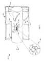
- FIG. 2shows a perspective, partially sectioned view of an embodiment of the fan 120 of FIG. 1, which is shown by way of example as a so-called pipe ventilator.
- Thishas a tube 260 in which the (not shown) inner stator of the ECM 110 is disposed in a Statortopf 270, which is fastened for example by means (not shown) spokes in the tube 260.
- an outer rotor 250rotates about the stator 270, on the periphery of which the fan blade 122 provided with fan blades 220 is mounted.
- the vanes 220in use, produce an air flow 125 which is transported axially to the left through the tube 260. For this reason, such a fan is called an axial fan. 2 shows on the right the inflow side with a protective grille 262 and on the left the outflow side of the fan 120.
- an air guide tube 248is provided on the Statortopf 270, in which at least a portion of the detection device 140 is arranged.
- An exemplary thermal anemometeris described in FIG.
- the sensors 242, 244are thermally decoupled to allow a determination of the flow rate of the air volume flow 125 via their differential heating. This thermal decoupling can be enhanced by corresponding slots in the circuit board 245. From the flow velocity, the volumetric flow measured value Vmess is derived.
- a temperature sensor 246is provided, which faces the fan wheel 122 and serves to measure the current temperature Tu. Since contamination of the sensors 242, 244 can negatively affect the measurement of the air volume flow 125 and the temperature sensor 246 is insensitive to contamination, it serves as a strainer for the two sensors 242, 244th
- FIG. 2An enlarged detail view of the Lucasleitrohrs 248 provided at the Statortopf 270 with the therein PCB 245 and the sensors 242, 244, 246 is shown in Fig. 2 at 280 in plan view from the left. Since the sensors 242, 244, 246 are arranged in a line one behind the other so that the temperature sensor 246 can serve as a strainer for the semiconductor sensors 242, 244, only the semiconductor sensor 242 is visible at 280.
- the air duct 248causes a uniform flow of air to pass over the sensors 242, 244, 246 to allow accurate measurement of the air volumetric flow 125. This is necessary because at maximum back pressure no air is conveyed through the pipe 260, but in the area of the air duct 248 due to the action of the fan wheel 122 still a strong swirling air flow can occur. This can strongly falsify the measurement of the flow velocity and is therefore suppressed by the action of the air guide tube 248.
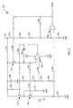
- FIG. 3shows a simplified circuit diagram of an exemplary circuit 300 with which a thermal anemometer according to a preferred embodiment is realized.
- the circuit 300comprises two bipolar transistors 310, 320, which in FIG. 2 serve as semiconductor sensors 242, 244 for measuring the air volume flow 125.
- the collector of the transistor 310is on the one hand via a resistor 344 with its base and on the other hand connected via a line 342 to a supply voltage source Vcc. Its emitter is connected to the collector and base of the transistor 320. Its base is connected via a line 362 to the output of an operational amplifier 385 and via two series-connected resistors 364, 376 to a line 382, which on the one hand to the non-inverting input of the operational amplifier 385 and on the other hand via two series-formed resistors 384, 386 is connected to a line 392.
- the operational amplifier 385is driven using the supply voltage source Vcc and ground GND.
- the inverting input of this operational amplifier 385is connected via a resistor 378 to the base of the transistor 320, which is connected via a resistor 374 to ground GND.
- the emitter of the transistor 320is connected on the one hand to a line 392 and on the other hand via a resistor 394 to ground GND.
- the line 342is connected via a capacitor 346 to ground and also to the collector of an npn transistor 330, whose emitter is connected on the one hand via a capacitor 366 to the line 362 and on the other hand to the inverting input of the operational amplifier 385. Its base is connected via a line 332 to the output of an operational amplifier 395, which is also connected via a resistor 398 to its inverting input and at which the volumetric flow measurement Vmess is generated.
- the inverting input of the operational amplifier 395is also connected via a series connection of two arranged in a line 302 resistors 304, 306 with Vcc and a resistor 396 to ground GND.
- the non-inverting input of operational amplifier 395is connected to line 392.
- the operational amplifier 385In operation of the circuit 300, the operational amplifier 385, regardless of thermal resistance and ambient temperature changes, causes a predetermined, approximately constant temperature difference of, for example, 25 ° C between the two series-connected transistors 310, 320, through which a current I Q flows.
- the operational amplifier 385accomplishes this by maintaining a constant ratio between the base-emitter voltages (UBE) of the transistors 310, 320, the power dissipation of which is controlled by influencing the current IQ.
- UBEbase-emitter voltages
- both transistors 310, 320carry the same current I Q , their relative energy output is determined only via their collector-emitter voltage (UCE).
- the circuit 300is designed such that, in operation, the collector-emitter voltage of the transistor 310 (UCE1) is greater than the collector-emitter voltage of the transistor 320 (UCE2). Therefore, regardless of the magnitude of the current IQ, the transistor 310 receives more energy and therefore becomes warmer than the diode-connected transistor 320. If now the air flow rate of the fan 120 increases, the thermal resistance of the transistors 310, 320 and decreases the operational amplifier 385 holds the predefined temperature difference constant by increasing the current I Q. This is detected by the resistor 394 and amplified by the operational amplifier 395, at whose output the measured value Vmess is generated.
- the operational amplifier 395in cooperation with the transistor 330, limits the voltage across the resistor 394 to a maximum of 2 V. Thus, blocking is prevented which would occur when the output of the operational amplifier 385 rises to approximately 5 V. In this case, UCE1 would approach the value UCE2 and it would be impossible to reach the given temperature difference. Similarly, the resistors 344, 374 prevent blocking when the fan 120 is turned on. The quadratic ratio between IQ and the power of the transistors 310, 320 makes a good contribution to the linearization.
- FIG. 4shows a block diagram of another preferred embodiment of the fan 120 of FIG. 1, which is also shown in FIG. 4 analogous to FIG. 2 as a tube ventilator with the schematically indicated tube 260.
- the same and equivalent components as in Figs. 1 and 2are therefore omitted in Fig. 4 either, such as the ⁇ C 130 of Fig. 1 or the temperature sensor 248 of Fig. 2, or denoted by the same reference numerals and not again in detail described.
- FIG. 4illustrates an implementation of the sensing device 140 of FIG. 1 using a valve anemometer 410 and a Hall sensor 430 associated therewith.
- the valve anemometer 410has a baffle 420 connected to a torsion spring 422 and at one end a permanent magnet 424 carries, which generates a magnetic field at the Hall sensor 430.
- the storage flap 420is replaced by the air volume flow 125 deflected.
- the deflectiondepends on the air volume flow 125, ie, the greater the volume flow 125, the greater the deflection of the flap 420.
- the torsion spring 422counteracts the deflection of the flap 420 in order to move it to its rest position.
- the deflection of the flap 420is detected by the Hall sensor 430. Since the magnet 424 moves away from the Hall sensor 430 during a deflection of the flap 420, as can be seen in FIG. 4, the field strength of the magnet 424 occurring at the sensor 430 is a direct measure of the deflection of the flap 420 Field strength, for example, an analog Hall IC used to implement the sensor 430, in which the output or Hall voltage is directly proportional to the field strength. The value Vmess is derived from this Hall voltage.
- the fan 120may be position independent, i. regardless of any required orientation, be mounted.
- the magnet 424is designed as a counterweight to the weight of the deflectable wing of the flap 420.
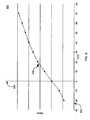
- FIG. 5is a measurement diagram 500 showing an exemplary Hall voltage 530 measured with the flap anemometer 410 of FIG. 4 versus different deflection angles of the damper 420. In this case, corresponding deflection angles are shown in degrees on the horizontal axis 510. On the vertical axis 520 Hall voltages measured at the respective deflections are shown.
- the Hall voltage 530is maximum when the flap 420 is in its rest position and decreases with increasing deflection.
- FIG. 6shows a routine "Init V offset " S600, which is used during the initialization or initialization of the fan 120 of FIG. 1, 2 or 4, ie when the fan wheel 122 is at a standstill, by the temperature and offset compensation arrangement 150 of FIG 1 is executed.
- the routine S600is used to determine a correction value for the zero point adjustment or for the calibration of the fan 120.
- the fan 120Since the fan 120 is not in operation when the routine S600 is executed, it should be Fan 122 stand still and the volumetric flow rate Vmess therefore be equal to zero. As a rule, however, a measured value Vmess, which is not equal to zero, nevertheless can occur due to component tolerances. Therefore, the fan 120 is calibrated by the zero point adjustment effected by the routine S600.
- the ambient temperatureis measured by the temperature sensor 248 and set as the current temperature Tu.
- a correction value Vtemp associated with the current temperature Tuis determined for zeroing the measured value Vmess. Exemplary correction values as a function of corresponding actual temperatures Tu are shown in FIG. 8.
- V offset V offsetV measured - V temp determined for zero point adjustment.
- FIG. 7shows a routine "Calc V ist " S700 performed by the fan 120 of FIG. 1, 2, or 4 from the temperature and offset compensation assembly 150 of FIG. 1.
- the routine S700is used for temperature and offset compensation of the volumetric flow measured value Vmess, which has a dependent of the current temperature Tu error, which usually increases with increasing temperature Tu.
- a respective current temperature Tu and a correction value Vtemp associated therewithare determined at S702 and S704.
- the measured value Vmessis applied with the correction value Vtemp determined at S704 and the correction value Voffset determined at S608 (Fig. 6), exemplified by a subtraction operation.
- the routine S700ends at S709.
- routines S600 of FIG. 6 and S700 of FIG. 7may also be used separately.
- the calibration of the fan 120could already be done at the factory during production.
- an execution of the routine S600 at the startup of the fan 120can be omitted, so that only the routine S700 is to be executed in its operation.
- FIG. 8shows a diagram 800 which illustrates an exemplary characteristic curve 830 of the temperature profile of the air volume flow measurement according to embodiments of the invention.
- the characteristic 830defines the temperature-dependent correction values Vtemp which are used in the routines S600 of FIG. 6 and S700 of FIG.
- Fig. 9is an exemplary measurement report 900 shows the from the fan 120 (Fig. 1) generated air-flow rate with four different waveforms 930, 940, 950, 960.
- the generated volume flow measuring value VMeas on the horizontal axis 910is shown, and on the vertical axis 920, back pressure measurements ⁇ p are shown.
- the curve 930was determined during operation of the fan with maximum fan speed without the air volume flow control according to the invention.
- This curveillustrates the air volume flow that can be generated by the fan 120 at a specific backpressure ⁇ p, which is fan-specific.
- the air volume flow generated by the fan 120is not constant in this case, but is inversely proportional to the back pressure, i. the greater the backpressure, the smaller the air volume flow generated.
- the curves 940, 950, 960illustrate measurements when using the air volume flow control according to the invention according to FIGS. 2 to 4, wherein each of these curves is based on a different volumetric flow setpoint value V_s.
- V_svolumetric flow setpoint value
- FIG. 10shows an exemplary measurement protocol 1000 with four different measurement curves 1030, 1040, 1050, 1060, which illustrate the dependence of the rotational speed actual value N ist of the fan 120 depicted on the vertical axis 1010 on the backpressure ⁇ p depicted on the horizontal axis 1020. These were determined in each case during the determination of the measurement curves 930-960 of FIG. 9. Accordingly, the curve 1030 was determined during operation of the fan with maximum fan speed without the air volume flow control according to the invention as a basis for comparison.
- the curves 1040, 1050, 1060show measurements when using the air volume flow control according to the invention as shown in FIGS. 2 to 4. Each of these curves is based on a different volume flow setpoint V_s. As can be seen from the curves 1040, 1050, 1060, the fan 120 is operated with increasing backpressure ⁇ p with increasing speed in order to keep the air volume flow generated by this substantially constant.
Landscapes
- Engineering & Computer Science (AREA)
- Mechanical Engineering (AREA)
- General Engineering & Computer Science (AREA)
- Physics & Mathematics (AREA)
- Fluid Mechanics (AREA)
- Chemical & Material Sciences (AREA)
- Combustion & Propulsion (AREA)
- Control Of Positive-Displacement Air Blowers (AREA)
Abstract
Description
Translated fromGermanDie Erfindung betrifft eine Anordnung mit einem Lüfter, insbesondere mit einem Axiallüfter für die Belüftung eines Niedrigenergiehauses.The invention relates to an arrangement with a fan, in particular with an axial fan for the ventilation of a low energy house.
Niedrigenergiehäuser werden in der Regel zwangsbelüftet. Dabei sind zur Belüftung unterschiedlicher Räume je nach Nutzungsart verschiedene Luft-Volumenströme erforderlich. In einem Badezimmer wird beispielsweise ein kontinuierlicher Luft-Volumenstrom zwischen 5 l/s und 10 l/s gewünscht. Wenn geduscht oder gebadet wird, sollte der Luft-Volumenstrom z.B. auf 15 l/s gesteigert werden, um eine ausreichende Belüftung des Badezimmers zu gewährleisten. Um hierbei einen minimalen Luft-Volumenstrom bei unterschiedlichen Staudrücken zu gewährleisten, werden gewöhnlich Lüfter mit entsprechender Leistungsreserve eingesetzt. Derartige Lüfter fördern entsprechend ihrer charakteristischen Lüfterkennlinie bei maximal möglichem Staudruck den minimalen Luft-Volumenstrom, und bei niedrigerem Staudruck einen wesentlich größeren Luft-Volumenstrom. Bei zu hohem Luft-Volumenstrom geht jedoch viel Wärme verloren, und es ergibt sich eine unnötige Lärmbelastung, weil der Lüfter ständig bei hoher Drehzahl betrieben wird.Low-energy houses are usually forced-ventilated. Depending on the type of use, different air flow rates are required to ventilate different rooms. In a bathroom, for example, a continuous air volume flow between 5 l / s and 10 l / s is desired. When showering or bathing, the air flow rate should be e.g. be increased to 15 l / s to ensure adequate ventilation of the bathroom. In order to ensure a minimum air volume flow at different back pressures, fans are usually used with the appropriate power reserve. Such fans promote according to their characteristic fan characteristic at maximum backpressure the minimum air flow rate, and at lower back pressure a much larger air flow rate. However, if the air volume flow is too high, a lot of heat will be lost and unnecessary noise will be produced because the fan is constantly operating at high speed.
Derzeit sind Luft-Volumenstromregelungen für Radiallüfter mit vorwärtsgekrümmten Schaufeln bekannt, da bei diesen eine eindeutige Beziehung zwischen Luft-Volumenstrom und Drehmoment bzw. Motorstrom besteht. Deshalb ist in Abhängigkeit von der Drehzahl und jeweiligen Stromaufnahme eine geeignete Luft-Volumenstromregelung solcher Radiallüfter möglich.Currently, air flow controls for centrifugal fans with forward curved blades are known because of their unique relationship between air flow rate and torque or motor current. Therefore, depending on the speed and current consumption, a suitable air flow control of such radial fan is possible.
Radiallüfter sind jedoch wegen ihrer mechanischen Abmessungen und 90° Luftumlenkung zum Einbau in bereits vorhandene Lüftungsrohre in der Regel ungeeignet. Im Gegensatz hierzu können Anordnungen mit Axiallüftern meist direkt in vorhandene Lüftungsrohre eingebaut werden.However, radial fans are generally unsuitable for installation in already existing ventilation pipes because of their mechanical dimensions and 90 ° air deflection. In contrast, arrangements with axial fans can usually be installed directly in existing ventilation pipes.
Es ist deshalb eine Aufgabe der Erfindung, eine neue Lüfteranordnung bereit zu stellen.It is therefore an object of the invention to provide a new fan assembly.
Nach der Erfindung wird diese Aufgabe gelöst durch eine Anordnung gemäß Anspruch 1. Eine solche Anordnung ermöglicht es, einen den Lüfter antreibenden elektronisch kommutierten Motor (ECM) derart anzusteuern, dass der Lüfter einen im Wesentlichen konstanten Luft-Volumenstrom erzeugt. Hierzu wird die Drehzahl des ECM als Funktion eines jeweils gemessenen Luft-Volumenstrom des Lüfters so geregelt, dass dieser Volumenstrom etwa einem vorgegebenen Wert entspricht.According to the invention, this object is achieved by an arrangement according to claim 1. Such an arrangement makes it possible to control a fan driving electronically commutated motor (ECM) such that the fan generates a substantially constant air flow rate. For this purpose, the speed of the ECM is controlled as a function of each measured air volume flow of the fan so that this volume flow corresponds approximately to a predetermined value.
Eine bevorzugte Weiterbildung der Erfindung ist Gegenstand des Anspruchs 9. Man erhält hierdurch einen sehr kompakten und preiswerten Regelkreis für den ECM.A preferred embodiment of the invention is the subject of claim 9. This gives a very compact and inexpensive control circuit for the ECM.
Eine bevorzugte Weiterbildung der Erfindung ist Gegenstand des Anspruchs 16. Man erhält hierdurch einen einfachen und stabilen Regelkreis für den ECM.A preferred embodiment of the invention is the subject of claim 16. This gives a simple and stable control loop for the ECM.
Weitere Einzelheiten und vorteilhafte Weiterbildungen der Erfindung ergeben sich aus den im folgenden beschriebenen und in der Zeichnung dargestellten, in keiner Weise als Einschränkung der Erfindung zu verstehenden Ausführungsbeispielen, sowie aus den übrigen Unteransprüchen. Es zeigt:
- Fig. 1
- ein Blockdiagramm einer Lüfteranordnung gemäß einer Ausführungsform,
- Fig. 2
- eine raumbildliche Darstellung einer Lüfteranordnung mit thermischem Anemometer gemäß einer Ausführungsform,
- Fig. 3
- ein Schaltungsdiagramm des thermischen Anemometers der Fig. 2,
- Fig. 4
- ein Blockdiagramm einer Lüfteranordnung mit Klappen-Anemometer gemäß einer Ausführungsform,
- Fig. 5
- eine Kennlinie des Klappen-Anemometers von Fig. 4,
- Fig. 6
- ein Flussdiagramm für eine Initialisierungs-Routine der Lüfteranordnung von Fig. 2 oder Fig. 4,
- Fig. 7
- ein Flussdiagramm für eine Luft-Volumenstrom-Regelungsroutine im Betrieb der Lüfteranordnung von Fig. 2 oder Fig. 4,
- Fig. 8
- eine beispielhafte Kennlinie für einen bei Fig. 6 und Fig. 7 erforderlichen Korrekturwert,
- Fig. 9
- ein beispielhaftes Messprotokoll eines Lüfters mit Luft-Volumenstromregelung gemäß einer Ausführungsform, und
- Fig. 10
- ein anderes beispielhaftes Messprotokoll eines Lüfters mit Luft-Volumenstromregelung gemäß einer Ausführungsform.
- Fig. 1
- a block diagram of a fan assembly according to an embodiment,
- Fig. 2
- a three-dimensional representation of a fan assembly with thermal anemometer according to an embodiment,
- Fig. 3
- 2 is a circuit diagram of the thermal anemometer of FIG. 2;
- Fig. 4
- 1 is a block diagram of a flap anemometer fan assembly according to an embodiment;
- Fig. 5
- a characteristic of the valve anemometer of Fig. 4,
- Fig. 6
- 2 is a flow chart for an initialization routine of the fan assembly of FIG. 2 or FIG. 4;
- Fig. 7
- 3 is a flowchart for an air volume control routine during operation of the fan assembly of FIG. 2 or FIG. 4;
- Fig. 8
- an exemplary characteristic curve for a correction value required in FIGS. 6 and 7,
- Fig. 9
- an exemplary measurement protocol of a fan with air volume flow control according to an embodiment, and
- Fig. 10
- another exemplary measurement protocol of a fan with air flow control according to one embodiment.
In der nachfolgenden Beschreibung beziehen sich die Begriffe links, rechts, oben und unten auf die jeweilige Zeichnungsfigur und können in Abhängigkeit von einer jeweils gewählten Ausrichtung (Hochformat oder Querformat) von einer Zeichnungsfigur zur nächsten variieren. Gleiche oder gleich wirkende Teile werden in den verschiedenen Figuren mit denselben Bezugszeichen bezeichnet und gewöhnlich nur einmal beschrieben.In the following description, the terms left, right, up and down refer to the respective drawing figure, and may vary from one drawing figure to the next, depending on a particular orientation (portrait or landscape). Identical or equivalent parts are denoted by the same reference numerals in the various figures and usually described only once.
Fig. 1 zeigt eine Lüfteranordnung 100 mit einem Lüfter 120, welcher ein Lüfterrad 122 hat. Dem Lüfter 120 ist zu seinem Antrieb ein von einem Mikrocontroller (Mikroprozessor) µC 130 gesteuerter ECM 110 zugeordnet. Der Mikrocontroller 130 hat eine Temperatur- und Offset-Kompensationsanordnung COMP 150, eine Volumenstrom-Regelanordnung V-RGL 160, und einen Drehzahlregler N-RGL 170.1 shows a
Eingangsseitig ist der µC 130 mit einer Erfassungsvorrichtung FLOW SENSOR 140 zur Erfassung eines vom Lüfter 120 erzeugten Luft-Volumenstroms, welcher mit Pfeilen 125 schematisch angedeutet ist, und dem ECM 110 verbunden. Ausgangsseitig ist der µC 130 mit dem ECM 110 verbunden.On the input side, the
Es wird darauf hingewiesen, dass die Anordnung 150 beispielhaft als eine einzelne Komponente dargestellt ist. Deren Funktionen können jedoch ebenso durch unterschiedliche Komponenten ausgeführt werden, welche getrennt voneinander realisiert werden.It should be understood that the
lm Betrieb der Anordnung 100 wird der Lüfter 120 von dem ECM 110 angetrieben, wobei das Lüfterrad 122 in Drehung versetzt wird und einen Luft-Volumenstrom 125 in Richtung zur Erfassungsvorrichtung 140 erzeugt. Dieser wird von der Erfassungsvorrichtung 140 erfasst, welche hierfür einen Volumenstrom-Messwert Vmess erzeugt.In operation of the
Die Erzeugung dieses Messwerts Vmess erfolgt unter Verwendung einer hierzu geeigneten Vorrichtung, beispielsweise eines thermischen Anemometers oder eines Klappen-Anemometers. Ein beispielhaftes thermisches Anemometer mit Halbleitersensoren wird nachstehend bei Fig. 3 beschrieben. Ein beispielhaftes Klappen-Anemometer mit Magnetsensor wird nachstehend bei Fig. 4 beschrieben. Es wird darauf hingewiesen, dass die Erfassung des Luft-Volumenstroms 125 und die Erzeugung des Messwerts Vmess auf jede hierfür geeignete Art und Weise erfolgen kann. Z.B. kann anstelle der beschriebenen Anemometer auch ein beliebiges anderes Anemometer verwendet werden, z.B. ein thermisches Hitzdrahtanemometer, ein Klappen-Anemometer mit Potentiometer, oder ein Windradanemometer zur Messung des Luft-Volumenstroms und zur Erzeugung des Messwerts Vmess.The generation of this measured value Vmess is carried out using a device suitable for this purpose, for example a thermal anemometer or a flap anemometer. An exemplary thermal anemometer with semiconductor sensors will be described below with reference to FIG. An exemplary flap anemometer with magnetic sensor will be described below with reference to FIG. It should be noted that the detection of the
Der Messwert Vmess und die aktuelle Temperatur Tu werden der Temperatur- und Offset-Kompensationsanordnung 150 zugeführt. Diese ist dazu ausgebildet, bei der Inbetriebnahme des Lüfters 120 den Messwert Vmess in Abhängigkeit von der aktuellen Temperatur Tu zu korrigieren und im Betrieb des Lüfters 120 einen im Messwert Vmess durch die Erfassungsvorrichtung 140 entstehenden Offset zu kompensieren. Hierzu hat die Anordnung 150 eine Speichereinheit 152, in welcher von der aktuellen Temperatur Tu abhängige Korrekturwerte zur Korrektur des Messwerts Vmess gespeichert sind. Aus dieser Speichereinheit 152 bestimmt die Anordnung 150 bei der Inbetriebnahme des Lüfters 120 abhängig von einer jeweils bestimmten aktuellen Temperatur Tu einen entsprechenden Korrekturwert, mit dem der Messwert Vmess korrigiert wird. Ein beispielhaftes Verfahren zur Temperaturkompensation des Messwerts Vmess bei Inbetriebnahme des Lüfters 120 wird bei Fig. 6 beschrieben. Beispielhafte Korrekturwerte werden bei Fig. 8 beschrieben.The measured value Vmess and the current temperature Tu are supplied to the temperature and offset
Im Betrieb des Lüfters 120 bestimmt die Anordnung 150 bei einer vorgegebenen Lüfterdrehzahl den durch die Erfassungsvorrichtung 140 erzeugten Offset des Messwerts Vmess und korrigiert diesen abhängig von der aktuellen Temperatur Tu. Der korrigierte Offset wird als temperaturkompensierter Offset abgespeichert und dem tatsächlichen Volumenstrom-Messwert durch einen Additions- oder Subtraktionsvorgang zwecks Offset-Kompensation beaufschlagt. Ein beispielhaftes Verfahren zur Offset-Kompensation des tatsächlichen Messwerts im Betrieb des Lüfters 120 wird bei Fig. 7 beschrieben.During operation of the
Der Temperatur- und Offset-kompensierte Messwert Vmess, welcher nachfolgend auch als als Vist bezeichnet wird, wird mit einem Volumenstrom-Sollwert V_s verknüpft und der Regelanordnung 160 zugeführt. Hierbei erfolgt beispielsweise ein Vergleich der beiden Werte, um eine Abweichung des Werts Vist vom Sollwert V_s zu bestimmen. Die Anordnung 160 ermittelt in Abhängigkeit von der ermittelten Abweichung einen Drehzahl-Sollwert N_s für den ECM 110.The temperature- and offset-compensated measured value Vmess, which is also referred to below as Vist, is linked to a volumetric flow setpoint value V_s and fed to the
Der Drehzahl-Sollwert N_s wird mit dem Drehzahl-lstwert Nist verknüpft und dem Drehzahlregler 170 zugeführt. Die Bestimmung des lstwerts Nist kann durch jede beliebige geeignete Vorrichtung zur Drehzahlbestimmung erfolgen, beispielsweise unter Verwendung von analogen oder digitalen Rotorstellungssensoren. Bei der Verknüpfung beider Werte wird vorzugsweise eine Abweichung des Istwerts Nist von dem Sollwert N_s bestimmt. Der Drehzahlregler 170 erzeugt unter Verwendung dieser Abweichung eine Stellgröße S, welche zur Regelung der Drehzahl des ECM 110 auf den von der Volumenstrom-Regelanordnung 160 erzeugten Drehzahl-Sollwert N_s dient.The speed setpoint N_s is supplied with the speed actual value Nis linked, and the speed controller 170th The determination of the actual value Nist can be made by any suitable device for speed determination, for example using analog or digital rotor position sensors. When linking both values, a deviation of the actual value Nist from the setpoint value N_s is preferably determined. Using this deviation, the
Dies ermöglicht es, den ECM 110 derart anzusteuern, dass der Lüfter 120 unabhängig von seiner Bauart einen etwa konstanten Luft-Volumenstrom erzeugt.This makes it possible to control the
Fig. 2 zeigt eine perspektivische, teilweise geschnittene Ansicht einer Ausführungsform des Lüfters 120 von Fig. 1, welcher beispielhaft als sogenannter Rohrlüfter dargestellt ist. Dieser hat ein Rohr 260, in dem der (nicht dargestellte) Innenstator des ECM 110 in einem Statortopf 270 angeordnet ist, welcher z.B. mittels (nicht dargestellter) Speichen in dem Rohr 260 befestigt ist. Um den Stator 270 herum rotiert im Betrieb ein Außenrotor 250, auf dessen Peripherie das mit Lüfterflügeln 220 versehene Lüfterrad 122 befestigt ist. Die Flügel 220 erzeugen im Betrieb einen Luft-Volumenstrom 125, der nach links axial durch das Rohr 260 transportiert wird. Aus diesem Grunde nennt man einen solchen Lüfter einen Axiallüfter. Fig. 2 zeigt rechts die Zuströmseite mit einem Schutzgitter 262 und links die Abströmseite des Lüfters 120.FIG. 2 shows a perspective, partially sectioned view of an embodiment of the
Gemäß einer bevorzugten Ausführungsform ist an dem Statortopf 270 ein Luftleitrohr 248 vorgesehen, in dem zumindest ein Teil der Erfassungsvorrichtung 140 angeordnet ist. Diese umfasst in Fig. 2 beispielhaft eine Leiterplatte 245 und zwei darauf angeordnete Halbleitersensoren 242, 244 zur Erfassung des Luft-Volumenstroms 125, welche Teil eines thermischen Anemometers sind. Ein beispielhaftes thermisches Anemometer wird bei Fig. 3 beschrieben.According to a preferred embodiment, an
Die Sensoren 242, 244 sind thermisch entkoppelt, um eine Bestimmung der Strömungsgeschwindigkeit des Luft-Volumenstroms 125 über deren differentielle Erwärmung zu ermöglichen. Diese thermische Entkopplung kann durch entsprechende Schlitze in der Leiterplatte 245 verstärkt werden. Aus der Strömungsgeschwindigkeit wird der Volumenstrom-Messwert Vmess abgeleitet.The
Rechts von den beiden Sensoren 242, 244 ist ein Temperatursensor 246 vorgesehen, der dem Lüfterrad 122 zugewandt ist und zur Messung der aktuellen Temperatur Tu dient. Da sich eine Verschmutzung der Sensoren 242, 244 negativ auf die Messung des Luft-Volumenstroms 125 auswirken kann und der Temperatursensor 246 unempfindlich gegen Verschmutzung ist, dient er als Schmutzfänger für die beiden Sensoren 242, 244.To the right of the two
Eine vergrößerte Detailansicht des am Statortopf 270 vorgesehenen Luftleitrohrs 248 mit der darin angeordneten Leiterplatte 245 und den Sensoren 242, 244, 246 ist in Fig. 2 bei 280 in Draufsicht von links gezeigt. Da die Sensoren 242, 244, 246 in einer Linie hintereinander angeordnet sind, damit der Temperatursensor 246 als Schmutzfänger für die Halbleitersensoren 242, 244 dienen kann, ist bei 280 nur der Halbleitersensor 242 sichtbar.An enlarged detail view of the
Das Luftleitrohr 248 bewirkt, dass eine gleichförmige Luftströmung über die Sensoren 242, 244, 246 geleitet wird, um eine akkurate Messung des Luft-Volumenstroms 125 zu ermöglichen. Dies ist erforderlich, da bei maximalem Gegendruck keine Luft mehr durch das Rohr 260 gefördert wird, aber im Bereich des Luftleitrohrs 248 auf Grund der Wirkung des Lüfterrades 122 dennoch eine stark verwirbelte Luftströmung auftreten kann. Diese kann die Messung der Strömungsgeschwindigkeit stark verfälschen und wird deshalb durch die Wirkung des Luftleitrohrs 248 unterdrückt.The
Fig. 3 zeigt ein vereinfachtes Schaltbild einer beispielhaften Schaltung 300, mit welcher ein thermisches Anemometer gemäß einer bevorzugten Ausführungsform realisiert wird. Die Schaltung 300 umfasst zwei Bipolartransistoren 310, 320, welche bei Fig. 2 als Halbleitersensoren 242, 244 zur Messung des Luft-Volumenstroms 125 dienen.3 shows a simplified circuit diagram of an
Der Kollektor des Transistors 310 ist einerseits über einen Widerstand 344 mit seiner Basis und andererseits über eine Leitung 342 mit einer Versorgungsspannungsquelle Vcc verbunden. Sein Emitter ist mit Kollektor und Basis des Transistors 320 verbunden. Seine Basis ist über eine Leitung 362 mit dem Ausgang eines Operationsverstärkers 385 verbunden und über zwei in Reihen geschaltete Widerstände 364, 376 mit einer Leitung 382, welche einerseits mit dem nicht-invertierenden Eingang des Operationsverstärkers 385 und andererseits über zwei in Reihe gestaltete Widerstände 384, 386 mit einer Leitung 392 verbunden ist. Der Operationsverstärker 385 wird unter Verwendung der Versorgungsspannungsquelle Vcc und Masse GND angesteuert. Der invertierende Eingang dieses Operationsverstärkers 385 ist über einen Widerstand 378 mit der Basis des Transistors 320 verbunden, welche über einen Widerstand 374 mit Masse GND verbunden ist. Der Emitter des Transistors 320 ist einerseits mit einer Leitung 392 und andererseits über einen Widerstand 394 mit Masse GND verbunden.The collector of the
Die Leitung 342 ist über einen Kondensator 346 mit Masse verbunden und ebenso mit dem Kollektor eines npn-Transistors 330, dessen Emitter einerseits über einen Kondensator 366 mit der Leitung 362 und andererseits mit dem invertierenden Eingang des Operationsverstärkers 385 verbunden ist. Seine Basis ist über eine Leitung 332 mit dem Ausgang eines Operationsverstärkers 395 verbunden, welcher auch über einen Widerstand 398 mit dessen invertierendem Eingang verbunden ist und an dem der Volumenstrom-Messwert Vmess erzeugt wird. Der invertierende Eingang des Operationsverstärkers 395 ist darüber hinaus über eine Reihenschaltung zweier in einer Leitung 302 angeordneter Widerstände 304, 306 mit Vcc verbunden und über einen Widerstand 396 mit Masse GND. Der nicht-invertierende Eingang des Operationsverstärkers 395 ist mit der Leitung 392 verbunden.The
Im Betrieb der Schaltung 300 bewirkt der Operationsverstärker 385, unabhängig von thermischen Widerstands- und Umgebungstemperaturänderungen, eine vorgegebene, etwa konstante Temperaturdifferenz von beispielsweise 25° C zwischen den beiden in Reihe geschalteten Transistoren 310, 320, durch welche ein Strom IQ fließt. Der Operationsverstärker 385 erreicht dies durch Aufrechterhalten eines konstanten Verhältnisses zwischen den Basis-Emitter-Spannungen (UBE) der Transistoren 310, 320, deren Verlustleistung durch Beeinflussung des Stromes IQ gesteuert wird. Zwischen IQ und der Aufnahmeleistung der Transistoren 310, 320 besteht eine im Wesentlichen quadratische Beziehung.In operation of the
Da beide Transistoren 310, 320 denselben Strom lQ führen, wird ihre relative Energieabgabe nur über ihre Kollektor-Emitter-Spannung (UCE) bestimmt. Hierbei ist die Schaltung 300 derart ausgelegt, dass im Betrieb die Kollektor-Emitter-Spannung des Transistors 310 (UCE1) größer ist als die Kollektor-Emitter-Spannung des Transistors 320 (UCE2). Daher nimmt der Transistor 310 unabhängig von der Größe des Stromes IQ jeweils mehr Energie auf und wird daher wärmer als der als Diode geschaltete Transistor 320. Wird nun der Luft-Volumenstrom des Lüfters 120 erhöht, verringert sich der thermische Widerstand der Transistoren 310, 320 und der Operationsverstärker 385 hält die vorgegebene Temperaturdifferenz konstant, indem er den Strom IQ erhöht. Dieser wird vom Widerstand 394 erfasst und vom Operationsverstärker 395 verstärkt, an dessen Ausgang der Messwert Vmess erzeugt wird.Since both
Der Operationsverstärker 395 begrenzt im Zusammenspiel mit dem Transistor 330 die Spannung am Widerstand 394 auf maximal 2 V. Somit wird eine Sperrung verhindert, die auftreten würde, wenn der Ausgang des Operationsverstärkers 385 auf etwa 5 V ansteigt. In diesem Fall würde sich UCE1 dem Wert UCE2 nähern und es würde unmöglich sein, die vorgegebene Temperaturdifferenz zu erreichen. Ähnlich verhindern die Widerstände 344, 374 eine Sperrung beim Einschalten des Lüfters 120. Das zwischen IQ und der Aufnahmeleistung der Transistoren 310, 320 bestehende quadratische Verhältnis leistet einen guten Beitrag zur Linearisierung.The
Fig. 4 zeigt ein Blockdiagramm einer anderen bevorzugten Ausführungsform des Lüfters 120 von Fig. 1, welcher in Fig. 4 analog zu Fig. 2 ebenfalls als Rohrlüfter mit dem schematisch angedeuteten Rohr 260 dargestellt ist. Gleiche und gleich wirkende Komponenten wie in den Fig. 1 und 2 werden deshalb in Fig. 4 entweder weggelassen, wie z.B. der µC 130 von Fig. 1 oder der Temperatursensor 248 von Fig. 2, oder mit denselben Bezugszeichen gekennzeichnet und nicht nochmals im Detail beschrieben.FIG. 4 shows a block diagram of another preferred embodiment of the
Fig. 4 illustriert eine Realisierung der Erfassungsvorrichtung 140 von Fig. 1 unter Verwendung eines Klappen-Anemometers 410 und eines diesem zugeordneten Hall-Sensors 430. Das Klappen-Anemometer 410 hat eine Stauklappe 420, welche mit einer Torsionsfeder 422 verbunden ist und an einem Ende einen Permanentmagneten 424 trägt, welcher am Hall-Sensor 430 ein Magnetfeld erzeugt.FIG. 4 illustrates an implementation of the
Im Betrieb des Lüfters 120 wird die Stauklappe 420 durch den Luft-Volumenstrom 125 ausgelenkt. Die Auslenkung hängt vom Luft-Volumenstrom 125 ab, d.h. je stärker der Volumenstrom 125 ist, umso größer ist die Auslenkung der Klappe 420. Die Torsionsfeder 422 wirkt der Auslenkung der Klappe 420 entgegen, um diese in ihre Ruhestellung zu bewegen.During operation of the
Die Auslenkung der Klappe 420 wird mit dem Hall-Sensor 430 erfasst. Da sich der Magnet 424 bei einer Auslenkung der Klappe 420, wie aus Fig. 4 ersichtlich, von dem Hall-Sensor 430 entfernt, ist die am Sensor 430 auftretende Feldstärke des Magneten 424 ein direktes Maß für die Auslenkung der Klappe 420. Zur Erfassung dieser Feldstärke wird beispielsweise ein analoges Hall-lC zur Realisierung des Sensors 430 verwendet, bei dem die Ausgangs- bzw. Hallspannung direkt proportional zur Feldstärke ist. Aus dieser Hallspannung wird der Wert Vmess abgeleitet.The deflection of the
Durch eine Lagerung der Stauklappe 420 in ihrem Schwerpunkt kann der Lüfter 120 lageunabhängig, d.h. unabhängig von einer jeweils erforderlichen Ausrichtung, montiert werden. In einer besonders vorteilhaften Ausführung wird der Magnet 424 hierbei als Gegengewicht zum Gewicht des auslenkbaren Flügels der Klappe 420 ausgebildet.By supporting the
Fig. 5 zeigt ein Messdiagramm 500, das eine beispielhafte, mit dem Klappen-Anemometer 410 von Fig. 4 gemessene Hallspannung 530 in Abhängigkeit von unterschiedlichen Auslenkungswinkeln der Stauklappe 420 zeigt. Hierbei sind entsprechende Auslenkungswinkel in Gradangaben auf der horizontalen Achse 510 abgebildet. Auf der vertikalen Achse 520 sind bei den entsprechenden Auslenkungen gemessene Hallspannungen abgebildet.FIG. 5 is a measurement diagram 500 showing an
Wie Fig. 5 zeigt, ist die Hallspannung 530 maximal, wenn die Klappe 420 sich in ihrer Ruhestellung befindet und nimmt mit steigender Auslenkung ab.As shown in FIG. 5, the
Fig. 6 zeigt eine Routine "Init Voffset" S600, welche bei der Inbetriebnahme bzw. Initialisierung des Lüfters 120 von Fig. 1, 2 oder 4, d.h. bei Stillstand des Lüfterrads 122, von der Temperatur- und Offset-Kompensationsanordnung 150 der Fig. 1 ausgeführt wird. Die Routine S600 dient zur Bestimmung eines Korrekturwerts zum Nullpunktabgleich bzw. zur Kalibrierung des Lüfters 120.6 shows a routine "Init Voffset " S600, which is used during the initialization or initialization of the
Da der Lüfter 120 bei Ausführung der Routine S600 nicht im Betrieb ist, müsste sein Lüfterrad 122 stillstehen und der Volumenstrom-Messwert Vmess folglich gleich Null sein. In der Regel kann jedoch trotzdem ein Messwert Vmess, der ungleich Null ist, aufgrund von Bauteiltoleranzen auftreten. Deshalb wird der Lüfter 120 durch den von der Routine S600 bewirkten Nullpunktabgleich kalibriert.Since the
Bei S602 wird die Umgebungstemperatur vom Temperatursensor 248 gemessen und als aktuelle Temperatur Tu gesetzt.At S602, the ambient temperature is measured by the
Bei S604 wird aus einer in der Speichereinheit 152 der Anordnung 150 gespeicherten Tabelle ein der aktuellen Temperatur Tu zugeordneter Korrekturwert Vtemp zum Nullpunktabgleich des Messwerts Vmess bestimmt. Beispielhafte Korrekturwerte in Abhängigkeit entsprechender aktueller Temperaturen Tu sind in Fig. 8 dargestellt.At S604, from a table stored in the
Bei S606 wird der Volumenstrom-Messwert Vmess erfasst.At S606, the volume flow measured value Vmeasurement is recorded.
Bei S608 wird ein entsprechender Korrekturwert Voffset mit Voffset := Vmess - Vtemp zum Nullpunktabgleich ermittelt. Die Routine S600 endet dann bei S609.In S608 a corresponding correction value Voffset Voffset is: = Vmeasured - Vtemp determined for zero point adjustment. The routine S600 then ends at S609.
Fig. 7 zeigt eine Routine "Calc Vist" S700, welche im Betrieb des Lüfters 120 von Fig. 1, 2 oder 4 von der Temperatur- und Offset-Kompensationsanordnung 150 von Fig. 1 ausgeführt wird. Die Routine S700 dient zur Temperatur- und Offset-Kompensation des Volumenstrom-Messwerts Vmess, welcher einen von der aktuellen Temperatur Tu abhängigen Fehler aufweist, der in der Regel bei wachsender Temperatur Tu ansteigt.FIG. 7 shows a routine "Calc Vist " S700 performed by the
Analog zu S602 und S604 von Fig. 6 werden bei S702 und S704 eine jeweils aktuelle Temperatur Tu und ein dieser zugeordneter Korrekturwert Vtemp bestimmt.Analogously to S602 and S604 of FIG. 6, a respective current temperature Tu and a correction value Vtemp associated therewith are determined at S702 and S704.
Bei S706 wird analog zu S606 der durch den Lüfter 120 erzeugte Volumenstrom-Messwert Vmess erfasst, welcher jedoch temperatur- und offsetbedingt fehlerbehaftet ist. Deshalb erfolgt bei S708 eine Temperatur- und Offset-Kompensation.In S706, analogously to S606, the volumetric flow measured value Vmess generated by the
Wie Fig. 7 zeigt, wird bei S708 der Messwert Vmess mit dem bei S704 bestimmten Korrekturwert Vtemp und dem bei S608 (Fig. 6) bestimmten Korrekturwert Voffset beaufschlagt, hier beispielhaft durch einen Subtraktionsvorgang. Hierbei erhält man den Temperatur- und offsetkompensierten Wert Vist mit Vist := Vmess - Voffset - Vtemp. Die Routine S700 endet bei S709.As shown in Fig. 7, at S708, the measured value Vmess is applied with the correction value Vtemp determined at S704 and the correction value Voffset determined at S608 (Fig. 6), exemplified by a subtraction operation. The temperature-compensated and offset-compensated value Vist is obtained here with Vist: = Vmess-Voffset-Vtemp. The routine S700 ends at S709.
Es wird darauf hingewiesen, dass die Routinen S600 von Fig. 6 und S700 von Fig. 7 auch getrennt voneinander verwendet werden können. Z.B. könnte die Kalibrierung des Lüfters 120 bereits werksseitig bei der Fertigung erfolgen. Hierbei kann eine Ausführung der Routine S600 bei der Inbetriebnahme des Lüfters 120 entfallen, so dass lediglich die Routine S700 in dessen Betrieb auszuführen ist.It should be noted that the routines S600 of FIG. 6 and S700 of FIG. 7 may also be used separately. For example, For example, the calibration of the
Fig. 8 zeigt ein Diagramm 800, welches eine beispielhafte Kennlinie 830 des Temperaturgangs der Luft-Volumenstrommessung gemäß Ausführungsformen der Erfindung illustriert. Die Kennlinie 830 definiert die temperaturabhängigen Korrekturwerte Vtemp, welche bei den Routinen S600 von Fig. 6 und S700 von Fig. 7 verwendet werden.8 shows a diagram 800 which illustrates an exemplary
Wie aus Fig. 8 ersichtlich, sind entsprechende Temperaturen in ° C, welche die Temperaturen Tu darstellen, auf der horizontalen Achse 810 abgebildet. Auf der vertikalen Achse 820 sind die diesen zugeordneten Korrekturwerte Vtemp abgebildet. Diese nehmen bei der Kennlinie 830 mit steigender Temperatur Tu zu.As can be seen from FIG. 8, corresponding temperatures in ° C., which represent the temperatures Tu, are depicted on the
Fig. 9 zeigt ein beispielhaftes Messprotokoll 900 des vom Lüfter 120 (Fig. 1) erzeugten Luft-Volumenstroms mit vier verschiedenen Messkurven 930, 940, 950, 960. Hierbei ist der erzeugte Volumenstrom-Messwert Vmess auf der horizontalen Achse 910 abgebildet und auf der vertikalen Achse 920 sind Gegendruck-Messwerte △p dargestellt.Fig. 9 is an
Die Kurve 930 wurde bei Betrieb des Lüfters mit maximaler Lüfterdrehzahl ohne die erfindungsgemäße Luft-Volumenstromregelung bestimmt. Diese Kurve illustriert den bei einem bestimmten Gegendruck △p maximal von dem Lüfter 120 erzeugbaren Luft-Volumenstrom, welcher lüfterspezifisch ist. Wie die Kurve 930 verdeutlicht, ist der von dem Lüfter 120 erzeugte Luft-Volumenstrom hierbei nicht konstant, sondern verläuft umgekehrt proportional zum Gegendruck, d.h. je größer der Gegendruck, umso kleiner ist der erzeugte Luft-Volumenstrom.The
Die Kurven 940, 950, 960 illustrieren Messungen bei Verwendung der erfindungsgemäßen Luft-Volumenstromregelung gemäß den Fig. 2 bis 4, wobei jeder dieser Kurven ein unterschiedlicher Volumenstrom-Sollwert V_s zugrunde liegt. Wie aus den Kurven 940, 950, 960 ersichtlich, ist der von dem Lüfter 120 erzeugte Luft-Volumenstrom hierbei jeweils bis zu einem bestimmten Gegendruck etwa konstant.The
Fig. 10 zeigt ein beispielhaftes Messprotokoll 1000 mit vier verschiedenen Messkurven 1030, 1040, 1050, 1060, welche die Abhängigkeit des auf der vertikalen Achse 1010 abgebildeten Drehzahl-Istwerts Nist des Lüfters 120 von dem auf der horizontalen Achse 1020 abgebildeten Gegendruck Δp illustrieren. Diese wurden jeweils bei der Bestimmung der Messkurven 930 - 960 von Fig. 9 ermittelt. Dementsprechend wurde die Kurve 1030 bei Betrieb des Lüfters mit maximaler Lüfterdrehzahl ohne die erfindungsgemäße Luft-Volumenstromregelung als Vergleichsgrundlage bestimmt.10 shows an
Die Kurven 1040, 1050, 1060 zeigen Messungen bei Verwendung der erfindungsgemäßen Luft-Volumenstromregelung gemäß den Fig. 2 bis 4. Jeder dieser Kurven liegt ein unterschiedlicher Volumenstrom-Sollwert V_s zugrunde. Wie aus den Kurven 1040, 1050, 1060 ersichtlich, wird der Lüfter 120 bei wachsendem Gegendruck Δp mit steigender Drehzahl betrieben, um den von diesem erzeugten Luft-Volumenstrom im Wesentlichen konstant zu halten.The
Naturgemäß sind im Rahmen der vorliegenden Erfindung vielfache Abwandlungen und Modifikationen möglich.Naturally, many modifications and modifications are possible within the scope of the present invention.
Claims (25)
Translated fromGermanApplications Claiming Priority (1)
| Application Number | Priority Date | Filing Date | Title |
|---|---|---|---|
| DE102006020421 | 2006-04-24 |
Publications (3)
| Publication Number | Publication Date |
|---|---|
| EP1850013A2true EP1850013A2 (en) | 2007-10-31 |
| EP1850013A3 EP1850013A3 (en) | 2010-09-01 |
| EP1850013B1 EP1850013B1 (en) | 2012-05-02 |
Family
ID=38282996
Family Applications (1)
| Application Number | Title | Priority Date | Filing Date |
|---|---|---|---|
| EP07006494ANot-in-forceEP1850013B1 (en) | 2006-04-24 | 2007-03-29 | Ventilator assembly |
Country Status (3)
| Country | Link |
|---|---|
| US (1) | US7880421B2 (en) |
| EP (1) | EP1850013B1 (en) |
| AT (1) | ATE556276T1 (en) |
Cited By (4)
| Publication number | Priority date | Publication date | Assignee | Title |
|---|---|---|---|---|
| EP2093428A1 (en)* | 2008-02-25 | 2009-08-26 | Vent-Axia Group Limited | A fan assembly and method of controlling the volume flow rate of fluid through such an assembly |
| CN102192174A (en)* | 2010-03-19 | 2011-09-21 | 元山科技工业股份有限公司 | Fan rotating speed control method |
| EP3287641A1 (en)* | 2016-08-23 | 2018-02-28 | ebm-papst Mulfingen GmbH & Co. KG | Method for regulating the massflow of a ventilator |
| EP4204692A1 (en)* | 2021-09-03 | 2023-07-05 | Ziehl-Abegg Se | Method for quantitatively determining current operating-state-dependent variables, more particularly the current conveyed volumetric flow rate, of a fan, and fan for application of the method |
Families Citing this family (27)
| Publication number | Priority date | Publication date | Assignee | Title |
|---|---|---|---|---|
| KR100946719B1 (en)* | 2007-11-28 | 2010-03-12 | 영 춘 정 | Multi-programmable constant flow control device of variable speed non-commutator motor |
| US8159160B2 (en)* | 2008-12-30 | 2012-04-17 | International Business Machines Corporation | Apparatus, system, and method for improved fan control in a power supply |
| CN103534660B (en)* | 2011-06-16 | 2017-03-22 | Abb研究有限公司 | Method and system for fluid flow control in a fluid network system |
| US9835265B2 (en) | 2011-12-15 | 2017-12-05 | Honeywell International Inc. | Valve with actuator diagnostics |
| US8947242B2 (en) | 2011-12-15 | 2015-02-03 | Honeywell International Inc. | Gas valve with valve leakage test |
| US9851103B2 (en) | 2011-12-15 | 2017-12-26 | Honeywell International Inc. | Gas valve with overpressure diagnostics |
| US9995486B2 (en) | 2011-12-15 | 2018-06-12 | Honeywell International Inc. | Gas valve with high/low gas pressure detection |
| US9846440B2 (en) | 2011-12-15 | 2017-12-19 | Honeywell International Inc. | Valve controller configured to estimate fuel comsumption |
| US9074770B2 (en) | 2011-12-15 | 2015-07-07 | Honeywell International Inc. | Gas valve with electronic valve proving system |
| US8839815B2 (en) | 2011-12-15 | 2014-09-23 | Honeywell International Inc. | Gas valve with electronic cycle counter |
| US8905063B2 (en) | 2011-12-15 | 2014-12-09 | Honeywell International Inc. | Gas valve with fuel rate monitor |
| US8899264B2 (en) | 2011-12-15 | 2014-12-02 | Honeywell International Inc. | Gas valve with electronic proof of closure system |
| US9557059B2 (en) | 2011-12-15 | 2017-01-31 | Honeywell International Inc | Gas valve with communication link |
| NL2008774C2 (en) | 2012-03-19 | 2013-09-23 | Contronics Engineering B V | A determination method and a control method for a fluid displacement device, controller and system. |
| US10422531B2 (en) | 2012-09-15 | 2019-09-24 | Honeywell International Inc. | System and approach for controlling a combustion chamber |
| US9234661B2 (en) | 2012-09-15 | 2016-01-12 | Honeywell International Inc. | Burner control system |
| EP2868970B1 (en) | 2013-10-29 | 2020-04-22 | Honeywell Technologies Sarl | Regulating device |
| US10024439B2 (en) | 2013-12-16 | 2018-07-17 | Honeywell International Inc. | Valve over-travel mechanism |
| US10915669B2 (en) | 2014-06-20 | 2021-02-09 | Ademco Inc. | HVAC zoning devices, systems, and methods |
| US9841122B2 (en) | 2014-09-09 | 2017-12-12 | Honeywell International Inc. | Gas valve with electronic valve proving system |
| US9645584B2 (en) | 2014-09-17 | 2017-05-09 | Honeywell International Inc. | Gas valve with electronic health monitoring |
| US10503181B2 (en) | 2016-01-13 | 2019-12-10 | Honeywell International Inc. | Pressure regulator |
| US10564062B2 (en) | 2016-10-19 | 2020-02-18 | Honeywell International Inc. | Human-machine interface for gas valve |
| US11073281B2 (en) | 2017-12-29 | 2021-07-27 | Honeywell International Inc. | Closed-loop programming and control of a combustion appliance |
| US10697815B2 (en) | 2018-06-09 | 2020-06-30 | Honeywell International Inc. | System and methods for mitigating condensation in a sensor module |
| CN108799177B (en)* | 2018-06-19 | 2020-08-18 | 浙江贤丰机电设备有限公司 | Intelligent fan rotating speed control method |
| US11092346B2 (en)* | 2019-01-08 | 2021-08-17 | Johnson Controls Technology Company | Integrated zone control system |
Citations (7)
| Publication number | Priority date | Publication date | Assignee | Title |
|---|---|---|---|---|
| US4806833A (en) | 1986-09-22 | 1989-02-21 | General Electric Company | System for conditioning air, method of operating such, and circuit |
| DE69101216T2 (en) | 1990-07-02 | 1994-09-22 | Cogema | METHOD AND DEVICE FOR REGULATING THE AMOUNT OF AIR IN A PIPELINE NETWORK. |
| EP0681150A2 (en) | 1994-05-02 | 1995-11-08 | Carrier Corporation | Airflow control for variable speed blowers |
| EP1039139A1 (en) | 1999-03-23 | 2000-09-27 | ebm Werke GmbH & Co. | Blower with characteristic curve |
| DE10035829A1 (en) | 1999-08-14 | 2001-04-26 | Ziehl Abegg Gmbh & Co Kg | Ventilating unit especially for stall ventilation, has speed of motor adjusted by alterating and operating voltage and actual volume flow is determined |
| DE10230242A1 (en) | 2002-07-04 | 2004-01-29 | Rational Ag | Operating method for electric fan unit for cooking appliance evaluates measured value for detecting motor overload or overheating for reducing motor revs |
| EP0848150B1 (en) | 1996-12-11 | 2004-05-12 | ABB Turbo Systems AG | Cleaning device for the turbine of a turbocharger |
Family Cites Families (14)
| Publication number | Priority date | Publication date | Assignee | Title |
|---|---|---|---|---|
| US4196628A (en)* | 1979-01-10 | 1980-04-08 | General Electric Company | Portable psychrometric test apparatus and method for air conditioning equipment |
| DE8229509U1 (en) | 1982-10-21 | 1983-08-04 | Gebrüder Trox, GmbH, 4133 Neukirchen-Vluyn | Control valve to keep the volume flow constant, especially in ventilation systems |
| US4978896A (en) | 1989-07-26 | 1990-12-18 | General Electric Company | Method and apparatus for controlling a blower motor in an air handling system |
| US5019757A (en) | 1990-03-19 | 1991-05-28 | General Electric Company | Method and apparatus for controlling a blower motor in an air handling system to provide constant pressure |
| US5415583A (en)* | 1993-12-21 | 1995-05-16 | Brandt, Jr.; Robert O. | Fume hood air flow control system |
| DE19804330A1 (en) | 1998-02-04 | 1999-08-12 | K Busch Gmbh Druck & Vakuum Dr | Process for regulating a compressor |
| US6286326B1 (en)* | 1998-05-27 | 2001-09-11 | Worksmart Energy Enterprises, Inc. | Control system for a refrigerator with two evaporating temperatures |
| DE29914892U1 (en) | 1999-08-25 | 1999-12-30 | Siemens AG, 80333 München | Control device for volume flow control, in particular of a blower |
| US6217437B1 (en)* | 1999-11-05 | 2001-04-17 | Lab Products, Inc. | Double-sided work station |
| DE10113249A1 (en) | 2001-03-19 | 2002-10-02 | Siemens Ag | Pressure generator for flowing media |
| US6504338B1 (en) | 2001-07-12 | 2003-01-07 | Varidigm Corporation | Constant CFM control algorithm for an air moving system utilizing a centrifugal blower driven by an induction motor |
| DE10220446C1 (en) | 2002-05-07 | 2003-10-16 | Enginion Ag | Gas flow regulation device for burner provides 2-stage regulation via fan with variable flow volume and choke element on output side of fan |
| US6905242B2 (en)* | 2003-01-16 | 2005-06-14 | Dwyer Instruments, Inc. | Sensor temperature control in a thermal anemometer |
| DE202005001746U1 (en) | 2004-08-20 | 2005-12-22 | Nash-Elmo Industries Gmbh | Fluidic machine controller, has governor module which from actual value and reference value produces set value supplied to both control module and to control unit |
- 2007
- 2007-03-29ATAT07006494Tpatent/ATE556276T1/enactive
- 2007-03-29EPEP07006494Apatent/EP1850013B1/ennot_activeNot-in-force
- 2007-04-18USUS11/736,621patent/US7880421B2/ennot_activeExpired - Fee Related
Patent Citations (7)
| Publication number | Priority date | Publication date | Assignee | Title |
|---|---|---|---|---|
| US4806833A (en) | 1986-09-22 | 1989-02-21 | General Electric Company | System for conditioning air, method of operating such, and circuit |
| DE69101216T2 (en) | 1990-07-02 | 1994-09-22 | Cogema | METHOD AND DEVICE FOR REGULATING THE AMOUNT OF AIR IN A PIPELINE NETWORK. |
| EP0681150A2 (en) | 1994-05-02 | 1995-11-08 | Carrier Corporation | Airflow control for variable speed blowers |
| EP0848150B1 (en) | 1996-12-11 | 2004-05-12 | ABB Turbo Systems AG | Cleaning device for the turbine of a turbocharger |
| EP1039139A1 (en) | 1999-03-23 | 2000-09-27 | ebm Werke GmbH & Co. | Blower with characteristic curve |
| DE10035829A1 (en) | 1999-08-14 | 2001-04-26 | Ziehl Abegg Gmbh & Co Kg | Ventilating unit especially for stall ventilation, has speed of motor adjusted by alterating and operating voltage and actual volume flow is determined |
| DE10230242A1 (en) | 2002-07-04 | 2004-01-29 | Rational Ag | Operating method for electric fan unit for cooking appliance evaluates measured value for detecting motor overload or overheating for reducing motor revs |
Cited By (5)
| Publication number | Priority date | Publication date | Assignee | Title |
|---|---|---|---|---|
| EP2093428A1 (en)* | 2008-02-25 | 2009-08-26 | Vent-Axia Group Limited | A fan assembly and method of controlling the volume flow rate of fluid through such an assembly |
| CN102192174A (en)* | 2010-03-19 | 2011-09-21 | 元山科技工业股份有限公司 | Fan rotating speed control method |
| EP3287641A1 (en)* | 2016-08-23 | 2018-02-28 | ebm-papst Mulfingen GmbH & Co. KG | Method for regulating the massflow of a ventilator |
| CN107762954A (en)* | 2016-08-23 | 2018-03-06 | 依必安-派特穆尔芬根股份有限两合公司 | The volume flow control method of ventilation blower |
| EP4204692A1 (en)* | 2021-09-03 | 2023-07-05 | Ziehl-Abegg Se | Method for quantitatively determining current operating-state-dependent variables, more particularly the current conveyed volumetric flow rate, of a fan, and fan for application of the method |
Also Published As
| Publication number | Publication date |
|---|---|
| EP1850013B1 (en) | 2012-05-02 |
| US7880421B2 (en) | 2011-02-01 |
| US20080124226A1 (en) | 2008-05-29 |
| ATE556276T1 (en) | 2012-05-15 |
| EP1850013A3 (en) | 2010-09-01 |
Similar Documents
| Publication | Publication Date | Title |
|---|---|---|
| EP1850013B1 (en) | Ventilator assembly | |
| US4392417A (en) | Variable dead band pressure control system | |
| JPS6231652B2 (en) | ||
| US6430985B1 (en) | Multiple point calibrated HVAC flow rate controller | |
| DE102007017682A1 (en) | Axial fan arrangement for ventilation of low-power building, has flow-controlling arrangement generating speed-reference value for electrically commutated motor, and speed controller controlling speed of motor to speed-reference value | |
| CA2418425C (en) | Method and device for measuring airflows through hvac grilles | |
| EP3504441B1 (en) | Fan comprising integrated flow control | |
| EP2508810A1 (en) | Ventilator module | |
| US4257318A (en) | Variable dead band pressure control system | |
| DE102017210123A1 (en) | An air handling system and measurement system and method for determining at least one parameter of an airflow exiting an air vent | |
| EP2556303B1 (en) | Pneumatic composite having mass balancing | |
| WO2021180260A1 (en) | Method for operating a temperature-control fan | |
| DE102004009605A1 (en) | Temperature sensor and arrangement for climate control of a motor vehicle interior | |
| DE4330922A1 (en) | Device for monitoring the air flow of a cooling device for a switchgear cabinet or an electronics housing | |
| CN113465149A (en) | System and method for characterizing Variable Air Volume (VAV) valves used in HVAC systems | |
| WO2021032255A1 (en) | Method for the quantitative determination of an actual operating state-dependent variable of a fan, in particular of a pressure change or pressure increase, and fan | |
| DE202017100465U1 (en) | Device for detecting a filter blockage | |
| EP3573737A1 (en) | Device and method for detecting filter clogging | |
| EP0984257B1 (en) | Autocalibrating device for measuring differential pressure | |
| WO2022268443A1 (en) | Monitoring device and method for monitoring the quality of a gas atmosphere | |
| DE102013217992A1 (en) | Room ventilation device and air flow control for a room ventilation device | |
| EP1413463B1 (en) | Arrangement for the determination of the interior temperature | |
| DE102016117323B3 (en) | Method for keeping constant the combustion air mass flow supplied to the burner chamber of a mobile heater and heating device operating according to such a method | |
| DE102015005125B4 (en) | Arrangement for detecting the temperature in the interior of a motor vehicle | |
| DE102020213419A1 (en) | Fan for determining a media flow moved by the fan and corresponding method |
Legal Events
| Date | Code | Title | Description |
|---|---|---|---|
| PUAI | Public reference made under article 153(3) epc to a published international application that has entered the european phase | Free format text:ORIGINAL CODE: 0009012 | |
| AK | Designated contracting states | Kind code of ref document:A2 Designated state(s):AT BE BG CH CY CZ DE DK EE ES FI FR GB GR HU IE IS IT LI LT LU LV MC MT NL PL PT RO SE SI SK TR | |
| AX | Request for extension of the european patent | Extension state:AL BA HR MK YU | |
| PUAL | Search report despatched | Free format text:ORIGINAL CODE: 0009013 | |
| AK | Designated contracting states | Kind code of ref document:A3 Designated state(s):AT BE BG CH CY CZ DE DK EE ES FI FR GB GR HU IE IS IT LI LT LU LV MC MT NL PL PT RO SE SI SK TR | |
| AX | Request for extension of the european patent | Extension state:AL BA HR MK RS | |
| AKX | Designation fees paid | Designated state(s):AT BE BG CH CY CZ DE DK EE ES FI FR GB GR HU IE IS IT LI LT LU LV MC MT NL PL PT RO SE SI SK TR | |
| 17P | Request for examination filed | Effective date:20110611 | |
| REG | Reference to a national code | Ref country code:DE Ref legal event code:R079 Ref document number:502007009796 Country of ref document:DE Free format text:PREVIOUS MAIN CLASS: F04D0027020000 Ipc:F24F0011000000 | |
| GRAP | Despatch of communication of intention to grant a patent | Free format text:ORIGINAL CODE: EPIDOSNIGR1 | |
| RIC1 | Information provided on ipc code assigned before grant | Ipc:F04D 27/02 20060101ALI20111026BHEP Ipc:F24F 11/00 20060101AFI20111026BHEP | |
| GRAJ | Information related to disapproval of communication of intention to grant by the applicant or resumption of examination proceedings by the epo deleted | Free format text:ORIGINAL CODE: EPIDOSDIGR1 | |
| GRAP | Despatch of communication of intention to grant a patent | Free format text:ORIGINAL CODE: EPIDOSNIGR1 | |
| GRAS | Grant fee paid | Free format text:ORIGINAL CODE: EPIDOSNIGR3 | |
| GRAA | (expected) grant | Free format text:ORIGINAL CODE: 0009210 | |
| AK | Designated contracting states | Kind code of ref document:B1 Designated state(s):AT BE BG CH CY CZ DE DK EE ES FI FR GB GR HU IE IS IT LI LT LU LV MC MT NL PL PT RO SE SI SK TR | |
| REG | Reference to a national code | Ref country code:GB Ref legal event code:FG4D Free format text:NOT ENGLISH | |
| REG | Reference to a national code | Ref country code:CH Ref legal event code:EP Ref country code:AT Ref legal event code:REF Ref document number:556276 Country of ref document:AT Kind code of ref document:T Effective date:20120515 | |
| REG | Reference to a national code | Ref country code:IE Ref legal event code:FG4D Free format text:LANGUAGE OF EP DOCUMENT: GERMAN | |
| REG | Reference to a national code | Ref country code:DE Ref legal event code:R096 Ref document number:502007009796 Country of ref document:DE Effective date:20120705 | |
| REG | Reference to a national code | Ref country code:NL Ref legal event code:VDEP Effective date:20120502 | |
| REG | Reference to a national code | Ref country code:LT Ref legal event code:MG4D Effective date:20120502 | |
| PG25 | Lapsed in a contracting state [announced via postgrant information from national office to epo] | Ref country code:CY Free format text:LAPSE BECAUSE OF FAILURE TO SUBMIT A TRANSLATION OF THE DESCRIPTION OR TO PAY THE FEE WITHIN THE PRESCRIBED TIME-LIMIT Effective date:20120502 Ref country code:PL Free format text:LAPSE BECAUSE OF FAILURE TO SUBMIT A TRANSLATION OF THE DESCRIPTION OR TO PAY THE FEE WITHIN THE PRESCRIBED TIME-LIMIT Effective date:20120502 Ref country code:FI Free format text:LAPSE BECAUSE OF FAILURE TO SUBMIT A TRANSLATION OF THE DESCRIPTION OR TO PAY THE FEE WITHIN THE PRESCRIBED TIME-LIMIT Effective date:20120502 Ref country code:LT Free format text:LAPSE BECAUSE OF FAILURE TO SUBMIT A TRANSLATION OF THE DESCRIPTION OR TO PAY THE FEE WITHIN THE PRESCRIBED TIME-LIMIT Effective date:20120502 Ref country code:IS Free format text:LAPSE BECAUSE OF FAILURE TO SUBMIT A TRANSLATION OF THE DESCRIPTION OR TO PAY THE FEE WITHIN THE PRESCRIBED TIME-LIMIT Effective date:20120902 Ref country code:SE Free format text:LAPSE BECAUSE OF FAILURE TO SUBMIT A TRANSLATION OF THE DESCRIPTION OR TO PAY THE FEE WITHIN THE PRESCRIBED TIME-LIMIT Effective date:20120502 | |
| PG25 | Lapsed in a contracting state [announced via postgrant information from national office to epo] | Ref country code:LV Free format text:LAPSE BECAUSE OF FAILURE TO SUBMIT A TRANSLATION OF THE DESCRIPTION OR TO PAY THE FEE WITHIN THE PRESCRIBED TIME-LIMIT Effective date:20120502 Ref country code:GR Free format text:LAPSE BECAUSE OF FAILURE TO SUBMIT A TRANSLATION OF THE DESCRIPTION OR TO PAY THE FEE WITHIN THE PRESCRIBED TIME-LIMIT Effective date:20120803 Ref country code:SI Free format text:LAPSE BECAUSE OF FAILURE TO SUBMIT A TRANSLATION OF THE DESCRIPTION OR TO PAY THE FEE WITHIN THE PRESCRIBED TIME-LIMIT Effective date:20120502 Ref country code:PT Free format text:LAPSE BECAUSE OF FAILURE TO SUBMIT A TRANSLATION OF THE DESCRIPTION OR TO PAY THE FEE WITHIN THE PRESCRIBED TIME-LIMIT Effective date:20120903 | |
| PG25 | Lapsed in a contracting state [announced via postgrant information from national office to epo] | Ref country code:NL Free format text:LAPSE BECAUSE OF FAILURE TO SUBMIT A TRANSLATION OF THE DESCRIPTION OR TO PAY THE FEE WITHIN THE PRESCRIBED TIME-LIMIT Effective date:20120502 Ref country code:EE Free format text:LAPSE BECAUSE OF FAILURE TO SUBMIT A TRANSLATION OF THE DESCRIPTION OR TO PAY THE FEE WITHIN THE PRESCRIBED TIME-LIMIT Effective date:20120502 Ref country code:SK Free format text:LAPSE BECAUSE OF FAILURE TO SUBMIT A TRANSLATION OF THE DESCRIPTION OR TO PAY THE FEE WITHIN THE PRESCRIBED TIME-LIMIT Effective date:20120502 Ref country code:RO Free format text:LAPSE BECAUSE OF FAILURE TO SUBMIT A TRANSLATION OF THE DESCRIPTION OR TO PAY THE FEE WITHIN THE PRESCRIBED TIME-LIMIT Effective date:20120502 Ref country code:DK Free format text:LAPSE BECAUSE OF FAILURE TO SUBMIT A TRANSLATION OF THE DESCRIPTION OR TO PAY THE FEE WITHIN THE PRESCRIBED TIME-LIMIT Effective date:20120502 Ref country code:CZ Free format text:LAPSE BECAUSE OF FAILURE TO SUBMIT A TRANSLATION OF THE DESCRIPTION OR TO PAY THE FEE WITHIN THE PRESCRIBED TIME-LIMIT Effective date:20120502 | |
| PLBE | No opposition filed within time limit | Free format text:ORIGINAL CODE: 0009261 | |
| STAA | Information on the status of an ep patent application or granted ep patent | Free format text:STATUS: NO OPPOSITION FILED WITHIN TIME LIMIT | |
| 26N | No opposition filed | Effective date:20130205 | |
| PG25 | Lapsed in a contracting state [announced via postgrant information from national office to epo] | Ref country code:ES Free format text:LAPSE BECAUSE OF FAILURE TO SUBMIT A TRANSLATION OF THE DESCRIPTION OR TO PAY THE FEE WITHIN THE PRESCRIBED TIME-LIMIT Effective date:20120813 | |
| REG | Reference to a national code | Ref country code:DE Ref legal event code:R097 Ref document number:502007009796 Country of ref document:DE Effective date:20130205 | |
| PG25 | Lapsed in a contracting state [announced via postgrant information from national office to epo] | Ref country code:BG Free format text:LAPSE BECAUSE OF FAILURE TO SUBMIT A TRANSLATION OF THE DESCRIPTION OR TO PAY THE FEE WITHIN THE PRESCRIBED TIME-LIMIT Effective date:20120802 | |
| BERE | Be: lapsed | Owner name:EBM-PAPST ST. GEORGEN G.M.B.H. & CO. KG Effective date:20130331 | |
| PG25 | Lapsed in a contracting state [announced via postgrant information from national office to epo] | Ref country code:MC Free format text:LAPSE BECAUSE OF NON-PAYMENT OF DUE FEES Effective date:20130331 | |
| REG | Reference to a national code | Ref country code:CH Ref legal event code:PL | |
| REG | Reference to a national code | Ref country code:IE Ref legal event code:MM4A | |
| PG25 | Lapsed in a contracting state [announced via postgrant information from national office to epo] | Ref country code:IE Free format text:LAPSE BECAUSE OF NON-PAYMENT OF DUE FEES Effective date:20130329 Ref country code:BE Free format text:LAPSE BECAUSE OF NON-PAYMENT OF DUE FEES Effective date:20130331 Ref country code:CH Free format text:LAPSE BECAUSE OF NON-PAYMENT OF DUE FEES Effective date:20130331 Ref country code:LI Free format text:LAPSE BECAUSE OF NON-PAYMENT OF DUE FEES Effective date:20130331 | |
| REG | Reference to a national code | Ref country code:AT Ref legal event code:MM01 Ref document number:556276 Country of ref document:AT Kind code of ref document:T Effective date:20130329 | |
| PG25 | Lapsed in a contracting state [announced via postgrant information from national office to epo] | Ref country code:MT Free format text:LAPSE BECAUSE OF FAILURE TO SUBMIT A TRANSLATION OF THE DESCRIPTION OR TO PAY THE FEE WITHIN THE PRESCRIBED TIME-LIMIT Effective date:20120502 | |
| PG25 | Lapsed in a contracting state [announced via postgrant information from national office to epo] | Ref country code:AT Free format text:LAPSE BECAUSE OF NON-PAYMENT OF DUE FEES Effective date:20130329 | |
| PG25 | Lapsed in a contracting state [announced via postgrant information from national office to epo] | Ref country code:TR Free format text:LAPSE BECAUSE OF FAILURE TO SUBMIT A TRANSLATION OF THE DESCRIPTION OR TO PAY THE FEE WITHIN THE PRESCRIBED TIME-LIMIT Effective date:20120502 | |
| PG25 | Lapsed in a contracting state [announced via postgrant information from national office to epo] | Ref country code:HU Free format text:LAPSE BECAUSE OF FAILURE TO SUBMIT A TRANSLATION OF THE DESCRIPTION OR TO PAY THE FEE WITHIN THE PRESCRIBED TIME-LIMIT; INVALID AB INITIO Effective date:20070329 Ref country code:LU Free format text:LAPSE BECAUSE OF NON-PAYMENT OF DUE FEES Effective date:20130329 | |
| REG | Reference to a national code | Ref country code:FR Ref legal event code:PLFP Year of fee payment:10 | |
| PGFP | Annual fee paid to national office [announced via postgrant information from national office to epo] | Ref country code:DE Payment date:20160301 Year of fee payment:10 Ref country code:IT Payment date:20160126 Year of fee payment:10 | |
| PGFP | Annual fee paid to national office [announced via postgrant information from national office to epo] | Ref country code:GB Payment date:20160304 Year of fee payment:10 Ref country code:FR Payment date:20160128 Year of fee payment:10 | |
| REG | Reference to a national code | Ref country code:DE Ref legal event code:R119 Ref document number:502007009796 Country of ref document:DE | |
| GBPC | Gb: european patent ceased through non-payment of renewal fee | Effective date:20170329 | |
| REG | Reference to a national code | Ref country code:FR Ref legal event code:ST Effective date:20171130 | |
| PG25 | Lapsed in a contracting state [announced via postgrant information from national office to epo] | Ref country code:FR Free format text:LAPSE BECAUSE OF NON-PAYMENT OF DUE FEES Effective date:20170331 Ref country code:DE Free format text:LAPSE BECAUSE OF NON-PAYMENT OF DUE FEES Effective date:20171003 | |
| PG25 | Lapsed in a contracting state [announced via postgrant information from national office to epo] | Ref country code:IT Free format text:LAPSE BECAUSE OF NON-PAYMENT OF DUE FEES Effective date:20170329 Ref country code:GB Free format text:LAPSE BECAUSE OF NON-PAYMENT OF DUE FEES Effective date:20170329 |