EP1848243B1 - Multi-channel echo compensation system and method - Google Patents
Multi-channel echo compensation system and methodDownload PDFInfo
- Publication number
- EP1848243B1 EP1848243B1EP06008006AEP06008006AEP1848243B1EP 1848243 B1EP1848243 B1EP 1848243B1EP 06008006 AEP06008006 AEP 06008006AEP 06008006 AEP06008006 AEP 06008006AEP 1848243 B1EP1848243 B1EP 1848243B1
- Authority
- EP
- European Patent Office
- Prior art keywords
- signal
- channel
- compensation
- loudspeaker
- signals
- Prior art date
- Legal status (The legal status is an assumption and is not a legal conclusion. Google has not performed a legal analysis and makes no representation as to the accuracy of the status listed.)
- Active
Links
Images


Classifications
- H—ELECTRICITY
- H04—ELECTRIC COMMUNICATION TECHNIQUE
- H04M—TELEPHONIC COMMUNICATION
- H04M9/00—Arrangements for interconnection not involving centralised switching
- H04M9/08—Two-way loud-speaking telephone systems with means for conditioning the signal, e.g. for suppressing echoes for one or both directions of traffic
- H04M9/082—Two-way loud-speaking telephone systems with means for conditioning the signal, e.g. for suppressing echoes for one or both directions of traffic using echo cancellers
- H—ELECTRICITY
- H04—ELECTRIC COMMUNICATION TECHNIQUE
- H04R—LOUDSPEAKERS, MICROPHONES, GRAMOPHONE PICK-UPS OR LIKE ACOUSTIC ELECTROMECHANICAL TRANSDUCERS; DEAF-AID SETS; PUBLIC ADDRESS SYSTEMS
- H04R3/00—Circuits for transducers, loudspeakers or microphones
- H04R3/02—Circuits for transducers, loudspeakers or microphones for preventing acoustic reaction, i.e. acoustic oscillatory feedback
- H—ELECTRICITY
- H04—ELECTRIC COMMUNICATION TECHNIQUE
- H04R—LOUDSPEAKERS, MICROPHONES, GRAMOPHONE PICK-UPS OR LIKE ACOUSTIC ELECTROMECHANICAL TRANSDUCERS; DEAF-AID SETS; PUBLIC ADDRESS SYSTEMS
- H04R2499/00—Aspects covered by H04R or H04S not otherwise provided for in their subgroups
- H04R2499/10—General applications
- H04R2499/13—Acoustic transducers and sound field adaptation in vehicles
- Y—GENERAL TAGGING OF NEW TECHNOLOGICAL DEVELOPMENTS; GENERAL TAGGING OF CROSS-SECTIONAL TECHNOLOGIES SPANNING OVER SEVERAL SECTIONS OF THE IPC; TECHNICAL SUBJECTS COVERED BY FORMER USPC CROSS-REFERENCE ART COLLECTIONS [XRACs] AND DIGESTS
- Y02—TECHNOLOGIES OR APPLICATIONS FOR MITIGATION OR ADAPTATION AGAINST CLIMATE CHANGE
- Y02D—CLIMATE CHANGE MITIGATION TECHNOLOGIES IN INFORMATION AND COMMUNICATION TECHNOLOGIES [ICT], I.E. INFORMATION AND COMMUNICATION TECHNOLOGIES AIMING AT THE REDUCTION OF THEIR OWN ENERGY USE
- Y02D30/00—Reducing energy consumption in communication networks
- Y02D30/70—Reducing energy consumption in communication networks in wireless communication networks
Definitions
- the inventionis directed to a multi-channel echo compensation system and method, in particular, to compensate for echoes that are present in a microphone signal and result from a multi-channel source.
- a typical exampleis a hands-free telephony system in a vehicular cabin.
- a telephony systemusually comprises one or more microphones to acquire speech signals from a speaker.
- some loudspeakersare mounted in the vehicular cabin as well. Via these loudspeakers, signals, from a radio or a CD player, for example, are output. These signals are also acquired by the microphones of the hands-free telephony system resulting in a distortion of the microphone signal.
- adaptive filtersare used to provide a compensating signal corresponding to the unwanted signals contained in the microphone signal.
- the adaptive filtersuse the input signals of the loudspeakers to determine a compensation signal that will be subtracted from the microphone signal.
- the structure of a conventional echo compensation systemis illustrated in Fig. 6 .
- three microphones 601are provided to acquire, first of all, speech signals from a speaker. However, these microphones also acquire audio signals coming from loudspeakers 602. On the microphone output channel 603 connected to the microphones, a beam-forming means 604 is provided to combine the microphone output signals in a suitable way.
- the signals h L ( n ) and h R ( n ) acquired by the microphone arrayare imitated by adaptive compensation filters 605 and 606. These adaptive filters use the loudspeaker input signals x L ( n ) and x R ( n ) (which can possibly be amplified in an amplifier 607) to provide a compensation signal d ⁇ ( n ) which comes as close as possible to the loudspeaker signal acquired by the microphones (which is denoted by d ( n )). By subtracting the compensation signal from the microphone signal, the portion in the microphone signal stemming from the loudspeaker is removed and the resulting signal e ( n ) becomes minimal.
- S x L x R ( ⁇ ), S x L x L ( ⁇ ) and S x R x R ( ⁇ )denote the cross-power spectral density and the auto-power spectral densities, respectively, of the signals x L ( n ) and x R ( n ) . If the coherence is very high, i.e. if the two signals are almost linearly dependent, the cost functions used in multi-channel adaptation algorithms do not have a unique solution. This has the consequence that, for example in the case of an interview, after a change of the speaker, the filters have to be balanced anew such that echoes occur again for a short time.
- echoesare distorting a microphone signal
- control devicessuch as a car radio or a system for passenger communication in a vehicular cabin.
- a non-linear pre-processingis performed on the radio signals which is indicated in Fig. 6 by a corresponding pre-processing means 609.
- a possible non-linear pre-processingmay consist of the addition of a half-wave rectifier (see for example, J. Benesty, T. Gänsler, D. R. Morgan, M. M. Sondhi, S. L. Gay, Advances in Network and Acoustic Echo Cancellation, Springer Verlag, Berlin, 2001 ).
- Another possibilityis a time variant pre-filtering as disclosed in A. Sugiyama, Y. Joncour, A. Hirano, A Stereo Echo Canceller with Correct Echo-Path Identification Based on an Input-Sliding Technique, IEEE Transactions on Signal Processing, Vol. 49, Nr. 1, Pages 2577-2587, 2001 .
- the United States patent US-B1-6 738 480discloses a hybrid technique allowing an appropriate echo cancellation scheme, mono or stereo, to be adapted on a dynamic basis.
- the inventionprovides a multi-channel echo compensation system, comprising:
- the pre-determined criterion to determine a correlation valuecan have different forms.
- the correlation valuecan be determined as the coherence value.
- the thresholdcan be selected to be 0.97. If the coherence value is greater than or equal to this value, the signals on the different input channels are considered to be highly correlated so that the adaptive filtering to provide a compensation signal can be performed with only one filter.
- the multi-channel echo compensation systemhas the further advantage that the required computing power can be reduced considerably in the case of highly correlated signals on different input channels.
- the computing power required to perform the adaptive filtering and the update of the filterscan be reduced by 50%.
- the above multi-channel echo compensation systemcan be concerned with the case of exactly two loudspeakers or more than two loudspeakers. In the latter case, a corresponding number of loudspeaker input channels, compensation channels, and adaptive compensation filters is provided. Then, if a correlation value is determined for two of the loudspeaker input channels which passes the pre-determined threshold, all but one of the adaptive compensation filters can be de-activated.
- the pre-processing meanscan be configured to provide a linear combination, particularly a difference and/or a sum, of signals of the two loudspeaker input channels to at least one of the adaptive compensation filters.
- Linear combinations of signalsallow to detect correlations between the signals in a very simple way.
- the pre-processing meanscan be configured to provide a sum of the signals of the two loudspeaker input channels to a first of the adaptive compensation filters and a difference of the signals of the two second loudspeaker input channels to a second of the adaptive compensation filters.
- the difference signalis very small or even zero. Therefore, it can be easily determined whether the two input signals are correlated or not.
- the pre-processing meanscan be configured to de-activate the second of the adaptive compensation filters if the determined correlation value passes the pre-determined threshold.
- the pre-processing meanscan be configured to determine a correlation value according to a pre-determined criterion based on the signal power of a signal, in particular, representing the difference and/or the sum of the signals of the two loudspeaker input channels.
- the difference of these signalshas almost vanishing power.
- the signal powercan be determined as the norm of a corresponding signal vector; thus, a very good indication of the correlation between the two signals is obtained.
- the correlation valuecan be determined recursively. This reduces the required computing power to determine the correlation value. For example, if the signal vectors have a length N, the squared norm of this vector at time n equals the squared norm of the vector at time n-1 plus the n-th value squared of the signal vector minus the (n-N)-th value squared of the signal vector.
- Each adaptive compensation filtercan be configured such that no adaptation of the adaptive compensation filter is performed if the adaptive compensation filter is de-activated. Such a configuration of the adaptive compensation filters further reduces the required computing power and increases the stability of the filters.
- the pre-processing meanscan comprise:
- the signal power of the subtracted signalwill be very low.
- the summed signalwill have a signal power which essentially corresponds to twice the signal power of the respective signals in the loudspeaker input channels. If the signal power of the subtracted signal is below a pre-determined threshold, this is a criterion to determine that the correlation is very high. Then, the adaptive filter being connected to the first output of the pre-processing means can be de-activated. The compensation of the microphone output signal can be based on the summed signal only which is input into the corresponding adaptive compensation filter.
- the pre-processing meanscan comprise a multiplying means on the first and/or the second signal path to multiply a signal on the first and/or on the second signal path by a weighting factor, in particular, to multiply the subtracted signal and the summed signal by a common weighting factor.
- the signals after summation or subtractionare a superposition of different signals.
- the signals on a first and a second loudspeaker input channelare highly correlated and summed in the pre-processing means, the corresponding summed signal corresponds to the signal on one of the loudspeaker input channels, but with twice the signal power. In that case, multiplying the summed signal by a factor of 0.5 leads to a resulting signal which essentially corresponds to the signal of one of the loudspeaker input channels.
- the pre-processing meanscan comprise a first adaptive pre-processing filter on the third signal path, the adaptation of which is based on the difference between the signals on the second and on the third signal path, and a second adaptive pre-processing filter on the fourth signal path, the adaptation of which is based on the difference between the signals on the first and on the fourth signal path.
- the two speakersare often placed on different sides in an acoustic way.
- one speakeris more present on a first channel, whereas the other speaker is more present on a second channel.
- the speech signals on both loudspeaker input channelsare still highly correlated, however, their difference would be non-zero.
- Providing adaptive pre-processing filters on the third and fourth signal pathsis useful in overcoming this problem.
- the adaptive compensation filters and the adaptive pre-processing filterscan be configured such that the adaptation of the pre-processing filters is performed slower than the adaptation of the compensation filters.
- the increments in the adaptation process of the pre-processing filterscan be smaller than the increments in the adaptation process of the compensation filters.
- the adaptation increments of the compensation filterscan be larger than the adaptation increments of the pre-processing filters. In this way, the adaptation of the pre-processing filters will be slower than that of the compensation filters.
- the pre-processing meanscan comprise a delay means on the first and on the second signal path, respectively, each delay means being configured to delay the signals on the first and on the second signal path before arriving at the summing means and subtracting means, respectively.
- the delay of the delay meanscan be selected such that it corresponds to about half of the length of a corresponding adaptive pre-processing filter. Then, about half of this adaptive pre-processing filter reproduces non-causal parts.
- the previously described multi-channel echo compensation systemscan comprise a summing means which is provided between the adaptive compensation filters and the microphone output channel and is configured to sum the signals emanating from the adaptive compensation filters.
- the at least one microphone of the above multi-channel echo compensation systemscan be configured as an array of at least two microphones being connected to a beam-forming means on the microphone output channel.
- the beam-forming meansyields a suitable directivity of the microphone array.
- the inventionalso provides a method for compensating echoes in a multi-channel system, the multi-channel system comprising two loudspeakers, each loudspeaker being connected to a loudspeaker input channel for providing a loudspeaker input signal to be emanated by the loudspeaker, at least one microphone for acquiring a signal emanating from the loudspeakers, the at least one microphone being connected to a microphone output channel, a compensation channel for each loudspeaker input channel, each compensation channel connecting a respective loudspeaker input channel and the microphone output channel, an adaptive compensation filter for each compensation channel, wherein each adaptive compensation filter is configured to filter a signal on the respective compensation channel such that a compensation output signal is provided to compensate a microphone output signal for a signal emanating from the loudspeakers, the method comprising the steps of:
- the pre-processing stepcan comprise providing a linear combination, particularly a difference and/or a sum, of signals of the two loudspeaker input channels to at least one of the adaptive compensation filters.
- the pre-processing stepcan comprise providing a sum of the signals of the first and the second loudspeaker input channel to a first of the adaptive compensation filters and a difference of the signals of the first and second loudspeaker input channels to a second of the adaptive compensation filters.
- the pre-processing stepcan comprise de-activating the second of the adaptive compensation filters if the determined correlation value passes the pre-determined threshold.
- the pre-processing stepcan comprise determining a correlation value according to a pre-determined criterion based on the signal power of a signal, in particular, representing the difference and/or the sum of the signals of the two loudspeaker input channels.
- the correlation valuecan be determined recursively.
- the pre-processing stepcan comprise summing the loudspeaker input signals on the two compensation input signals to obtain a summed signal and subtracting the loudspeaker input signals on the two compensation input signals to obtain a subtracted signal.
- the pre-processing stepcan comprise multiplying the summed signal and the subtracted signal by a weighting factor, in particular, by a common weighting factor.
- the pre-processing stepcan comprise:
- the adaptively filtering of the pre-processing stepcan be performed slower than the adaptation of the adaptive compensation filters.
- the adaptation increments of the compensation filterscan be chosen to be larger than the adaptation increments of the adaptively filtering of the pre-processing step.
- the pre-processing stepcan comprise:
- the delaycan be selected such that it corresponds to about half of the length of a corresponding filter for adaptively filtering in the pre-processing step.
- the above described methodscan comprise the step of summing the signals emanating from the adaptive compensation filters.
- the inventionalso provides a computer program product comprising one or more computer readable media having computer-executable instructions for performing the steps of the above described methods when run on a computer.
- Fig. 1illustrates schematically an embodiment of a multi-channel echo compensation system according to the present invention.
- a stereo signal sourcesuch as a car radio (not shown) outputs radio signals for a left loudspeaker channel x L ( n ) and for a right loudspeaker channel x R ( n ) .
- These radio signalsare emanated by two loudspeakers 102 and are acquired by a microphone array consisting of three microphones 101.
- nindicates the time dependence of the coefficients.
- the signals acquired by the microphones 101are output to a microphone output channel 103, on which a processing means 104 is provided.
- a processing meanscan perform a linear time invariant processing, for example, as it is done by a beam-former or a high-pass filter.
- the microphone output signal(in the example after the processing means 104) is denoted by d(n).
- the microphonesare mainly used to acquire speech signals from a speaker, for example, for a hands-free telephony system or for a hands-free control system of specific devices. In view of this, it is desirable to reduce radio signal components in the microphone output signal d(n).
- the order of the adaptive filters Nis smaller than the order of the impulse responses.
- 300 to 500 coefficients at a sampling rate of 11 kHzcan be used for the adaptive filters.
- This output signalis used to adapt the adaptive compensation filters.
- the adaptation of the filtersis to be performed in such a way that the estimated impulse response ⁇ L,i ( n ) and ⁇ R,i ( n ) are as close as possible to the real impulse responses h L,i ( n ) and h R,i ( n ) and that a high number of coefficients is estimated.
- the adaptation of the filterscan be performed via the NLMS algorithm
- each loudspeaker input channel 111 and 112is connected to the microphone output channel 103 by a corresponding compensation channel 113 and 114 such that each compensation channel receives a respective loudspeaker input signal.
- the pre-processing means 110comprises two inputs 115 and 116, each input being connected to a respective loudspeaker input channel via a compensation channel.
- the pre-processing means 110further comprises two outputs 117 and 118, these outputs being connected to the respective adaptive compensation filters 105 and 106.
- first signal path 119connecting the first input 115 and the first output 117; furthermore, there is a second signal path connecting the second input 116 and the second output 118.
- a subtracting means 121On the first signal path 119, a subtracting means 121, and on the second signal path 120, a summing means 122, are provided.
- a third signal path 123connects the first input 115 and the summing means 122, whereas a fourth signal path 124 connects the second input 116 and the subtracting means 121.
- the summing and the subtracting meansare followed by a multiplying means 125 to multiply the summed and the subtracted signals by a common weighting factor of 0.5.
- weighting with a factor of 0.5can be realized by shifting the result in the accumulation register by one bit.
- Fig. 2shows the variation in time of a typical stereo radio signal.
- the upper graphcorresponds to the left loudspeaker input channel and the lower graph to the right loudspeaker input channel.
- the power spectrum for the playback of newsis depicted; the right part corresponds to the playback of classical music.
- Fig. 3illustrates the signals x s ( n ) and x D ( n ) corresponding to the signals of Fig. 2 .
- the upper graphshows x s ( n ) weighted by a factor of 0.5 and the lower graph shows x D ( n ) weighted by a factor of 0.5.
- the difference signal x D ( n )vanishes or at least almost vanishes during this time period.
- the summed signals and the subtracted signalsdiffer only slightly from the original signals.
- the corresponding adaptive compensation filter 105is de-activated. Then, no adaptation of this adaptive compensation filter is performed so that the computing power required to adapt the filters is halved. However, although only one of the adaptive compensation filters is activated, the resulting echo reduction is unaltered to a large degree.
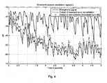
- FIG. 4This is illustrated in Fig. 4 .
- the variation of a microphone output signal d ( n ) in time without additional echo compensationis shown.
- an output signal e ( n )for which a conventional echo compensation as illustrated in Fig. 6 was performed, is depicted as a comparative example.
- the graphalso shows the short time power of an output signal e ( n ) for which an echo compensation according to Fig. 1 was performed.
- 4 dBwere added to the values of this last curve for better illustration. In other words, without the additional 4 dB, the curves of the output signals with the conventional and the novel echo compensation method would be almost indistinguishable.
- the radio signalcan be reduced by approximately 30 dB.
- the pre-processing means 110 and the adaptive filters 105 and 106have been depicted as separate elements. Then, control of the adaptive filters by the pre-processing means, in particular, de-activation of one of the adaptive filters, has to be performed via a corresponding control connection (not shown). However, it is to be understood that checking whether a correlation value is below a pre-determined threshold can also be performed at the input of an adaptive filter; in this case, the pre-processing means would comprise part of the adaptive filter as well.
- the conventional echo compensation method according to Fig. 6has the following convergence behavior for the adaptive compensation filters: h L n ⁇
- E e 2 n ⁇ minh L n , h ⁇ L n ⁇
- E e 2 n ⁇ minh ⁇ R n . under the condition that the signals are not completely correlated.
- the novel echo compensation method according to Fig. 1has the following convergence behavior, even if the input signals are fully correlated: h ⁇ S n ⁇
- E e 2 n ⁇ minh L n + h R n , h ⁇ D n ⁇
- E e 2 n ⁇ minh L n - h R n .
- FIG. 5An extension of the multi-channel echo compensation system illustrated in Fig. 1 is depicted schematically in Fig. 5 .
- the structure of the corresponding pre-processing meansis shown.
- This embodimentis particularly useful if, in an interview, one of the speakers is (acoustically) placed to the left and the other to the right. This can be done by varying the amplification of the right and the left channel, by inserting delay time elements, or by a combination of both. In addition, further filters for amending the tone can be used.
- additional adaptive pre-processing filters 526 and 527are provided along the third signal path 523 and the fourth signal path 524, respectively. Furthermore, on the first signal path 519 and the second signal path 520, a delay means 528 and 529, respectively, is provided. These delay means are provided before the summing and the subtracting means in the direction of the signal flow.
- the adaptation of the pre-processing filters 526 and 527can be performed via the NLMS algorithm, as in the case of the compensation filters.
- the adaptation of the pre-processing filters 526 and 527is performed slower than the adaptation of the compensation filters 105 and 106. This can be achieved, for example, by choosing smaller increments in the case of the adaptation of the pre-processing filters: 0 ⁇ ⁇ G ⁇ ⁇ ⁇ 1.
- the delay elements 528 and 529can be configured in such a way that the delay times of N V cycles are selected that about half of the corresponding filter reproduce non-causal parts: N V ⁇ N G 2 .
- the adaptive pre-processing of Fig. 5corresponds to the fixed pre-processing shown in Fig. 1 .
- the multi-channel echo compensation systemwas described for the case of a two-channel, i.e. stereo, system.
- the pre-processing meanscan be configured to de-activate all but one of the adaptive filters if a correlation value passes a pre-determined threshold.
Landscapes
- Engineering & Computer Science (AREA)
- Signal Processing (AREA)
- Health & Medical Sciences (AREA)
- General Health & Medical Sciences (AREA)
- Otolaryngology (AREA)
- Physics & Mathematics (AREA)
- Acoustics & Sound (AREA)
- Circuit For Audible Band Transducer (AREA)
- Telephone Function (AREA)
- Cable Transmission Systems, Equalization Of Radio And Reduction Of Echo (AREA)
- Interconnected Communication Systems, Intercoms, And Interphones (AREA)
Abstract
Description
- The invention is directed to a multi-channel echo compensation system and method, in particular, to compensate for echoes that are present in a microphone signal and result from a multi-channel source.
- The presence of echoes in a microphone signal is a problem occurring in different kinds of communication systems. A typical example is a hands-free telephony system in a vehicular cabin. Such a telephony system usually comprises one or more microphones to acquire speech signals from a speaker. However, some loudspeakers are mounted in the vehicular cabin as well. Via these loudspeakers, signals, from a radio or a CD player, for example, are output. These signals are also acquired by the microphones of the hands-free telephony system resulting in a distortion of the microphone signal.
- In order to compensate for these unwanted signals, adaptive filters are used to provide a compensating signal corresponding to the unwanted signals contained in the microphone signal. For this, the adaptive filters use the input signals of the loudspeakers to determine a compensation signal that will be subtracted from the microphone signal. The structure of a conventional echo compensation system is illustrated in
Fig. 6 . - In the system illustrated in this figure, three
microphones 601 are provided to acquire, first of all, speech signals from a speaker. However, these microphones also acquire audio signals coming fromloudspeakers 602. On themicrophone output channel 603 connected to the microphones, a beam-formingmeans 604 is provided to combine the microphone output signals in a suitable way. - The signalshL(n) andhR(n) acquired by the microphone array are imitated by
adaptive compensation filters - When compensating signals stemming from a
car radio 608, there is the problem that the absolute value squared of the coherence
L xR (Ω),SxL xL (Ω) andSxR xR (Ω) denote the cross-power spectral density and the auto-power spectral densities, respectively, of the signalsxL(n) andxR(n). If the coherence is very high, i.e. if the two signals are almost linearly dependent, the cost functions used in multi-channel adaptation algorithms do not have a unique solution. This has the consequence that, for example in the case of an interview, after a change of the speaker, the filters have to be balanced anew such that echoes occur again for a short time. - Other examples in which echoes are distorting a microphone signal are a hands-free system that is provided to control devices such as a car radio or a system for passenger communication in a vehicular cabin.
- During the past years, many efforts have been made to solve the above problem. According to one proposal, a non-linear pre-processing is performed on the radio signals which is indicated in
Fig. 6 by a corresponding pre-processing means 609. A possible non-linear pre-processing may consist of the addition of a half-wave rectifier (see for example, J. Benesty, T. Gänsler, D. R. Morgan, M. M. Sondhi, S. L. Gay, Advances in Network and Acoustic Echo Cancellation, Springer Verlag, Berlin, 2001). Another possibility is a time variant pre-filtering as disclosed inA. Sugiyama, Y. Joncour, A. Hirano, A Stereo Echo Canceller with Correct Echo-Path Identification Based on an Input-Sliding Technique, IEEE Transactions on Signal Processing, Vol. 49, Nr. 1, Pages 2577-2587, 2001. - The
United States patent US-B1-6 738 480 discloses a hybrid technique allowing an appropriate echo cancellation scheme, mono or stereo, to be adapted on a dynamic basis. - It is a drawback of these methods that the signals on their path from the signal source (i.e. the car radio) to the loudspeakers are modified resulting in audible artefacts.
- In view of the above-mentioned drawback of the prior art, it is the problem underlying the present invention to provide a multi-channel echo compensation system with improved echo compensation. This problem is solved by a system according to
claim 1 and a method according to claim 17. - Accordingly, the invention provides a multi-channel echo compensation system, comprising:
- two loudspeaker input channels, each loudspeaker input channel being connected to a loudspeaker for providing a loudspeaker input signal to be emanated by the loudspeaker,
- a microphone output channel being connected to at least one microphone for receiving a microphone output signal from the at least one microphone, wherein each microphone is configured to acquire a signal emanating from the loudspeakers,
- a compensation channel for each loudspeaker input channel, each compensation channel connecting a respective loudspeaker input channel and the microphone output channel,
- an adaptive compensation filter for each compensation channel, wherein each adaptive compensation filter is configured to filter a signal on the respective compensation channel such that a compensation output signal is provided to compensate a microphone output signal for a signal emanating from the loudspeakers,
- a pre-processing means for pre-processing loudspeaker input signals on the compensation channels, the pre-processing means being configured to determine a correlation value of the loudspeaker input signals for the two loudspeakers according to a pre-determined criterion and to de-activate one of the adaptive compensation filters if the determined correlation value passes a pre-determined threshold.
- By de-activating one of the adaptive compensation filters, the above-mentioned problem of a non-unique solution of the adaptation process is overcome.
- The pre-determined criterion to determine a correlation value can have different forms. For example, the correlation value can be determined as the coherence value. In this case, for example, the threshold can be selected to be 0.97. If the coherence value is greater than or equal to this value, the signals on the different input channels are considered to be highly correlated so that the adaptive filtering to provide a compensation signal can be performed with only one filter.
- The multi-channel echo compensation system according to the invention has the further advantage that the required computing power can be reduced considerably in the case of highly correlated signals on different input channels. In particular, in the case of exactly two loudspeakers, i.e. a stereo system, the computing power required to perform the adaptive filtering and the update of the filters can be reduced by 50%.
- The above multi-channel echo compensation system can be concerned with the case of exactly two loudspeakers or more than two loudspeakers. In the latter case, a corresponding number of loudspeaker input channels, compensation channels, and adaptive compensation filters is provided. Then, if a correlation value is determined for two of the loudspeaker input channels which passes the pre-determined threshold, all but one of the adaptive compensation filters can be de-activated.
- The pre-processing means can be configured to provide a linear combination, particularly a difference and/or a sum, of signals of the two loudspeaker input channels to at least one of the adaptive compensation filters.
- Linear combinations of signals, particularly differences of signals, allow to detect correlations between the signals in a very simple way.
- In particular, the pre-processing means can be configured to provide a sum of the signals of the two loudspeaker input channels to a first of the adaptive compensation filters and a difference of the signals of the two second loudspeaker input channels to a second of the adaptive compensation filters.
- In this way, if the signals of the first and the second loudspeaker input channel are highly correlated (for example, if the signal to be output by the loudspeaker is a mono-signal), the difference signal is very small or even zero. Therefore, it can be easily determined whether the two input signals are correlated or not.
- In this case, in particular, the pre-processing means can be configured to de-activate the second of the adaptive compensation filters if the determined correlation value passes the pre-determined threshold.
- The pre-processing means can be configured to determine a correlation value according to a pre-determined criterion based on the signal power of a signal, in particular, representing the difference and/or the sum of the signals of the two loudspeaker input channels.
- If the input signals are highly correlated, the difference of these signals has almost vanishing power. In particular, the signal power can be determined as the norm of a corresponding signal vector; thus, a very good indication of the correlation between the two signals is obtained.
- In the above multi-channel echo compensation system, the correlation value can be determined recursively. This reduces the required computing power to determine the correlation value. For example, if the signal vectors have a length N, the squared norm of this vector at time n equals the squared norm of the vector at time n-1 plus the n-th value squared of the signal vector minus the (n-N)-th value squared of the signal vector.
- Each adaptive compensation filter can be configured such that no adaptation of the adaptive compensation filter is performed if the adaptive compensation filter is de-activated. Such a configuration of the adaptive compensation filters further reduces the required computing power and increases the stability of the filters.
- In the above-described multi-channel echo compensation systems, the pre-processing means can comprise:
- two inputs, each input being connected to a respective loudspeaker input channel,
- two outputs, each output being connected to a respective adaptive compensation filter,
- a first signal path connecting the first input and the first output and a second signal path connecting the second input and the second output,
- a subtracting means on the first signal path and a summing means on the second signal path,
- a third signal path connecting the first input and the summing means such that a signal on the first signal path and a signal on the second signal path are summed to obtain a summed signal,
- and a fourth signal path connecting the second input and the subtracting means such that a signal on the first signal path and a signal on the second signal path are subtracted from each other to obtain a subtracted signal.
- This is a very advantageous implementation of a multi-channel echo compensation system. In particular, if the signals on the two loudspeaker input channels are highly correlated, the signal power of the subtracted signal will be very low. On the other hand, in this case, the summed signal will have a signal power which essentially corresponds to twice the signal power of the respective signals in the loudspeaker input channels. If the signal power of the subtracted signal is below a pre-determined threshold, this is a criterion to determine that the correlation is very high. Then, the adaptive filter being connected to the first output of the pre-processing means can be de-activated. The compensation of the microphone output signal can be based on the summed signal only which is input into the corresponding adaptive compensation filter.
- The pre-processing means can comprise a multiplying means on the first and/or the second signal path to multiply a signal on the first and/or on the second signal path by a weighting factor, in particular, to multiply the subtracted signal and the summed signal by a common weighting factor.
- In this way, one can take into account that the signals after summation or subtraction are a superposition of different signals. In particular, if the signals on a first and a second loudspeaker input channel are highly correlated and summed in the pre-processing means, the corresponding summed signal corresponds to the signal on one of the loudspeaker input channels, but with twice the signal power. In that case, multiplying the summed signal by a factor of 0.5 leads to a resulting signal which essentially corresponds to the signal of one of the loudspeaker input channels.
- The pre-processing means can comprise a first adaptive pre-processing filter on the third signal path, the adaptation of which is based on the difference between the signals on the second and on the third signal path, and a second adaptive pre-processing filter on the fourth signal path, the adaptation of which is based on the difference between the signals on the first and on the fourth signal path.
- When playing back an interview on a stereo channel system, for example, the two speakers are often placed on different sides in an acoustic way. In other words, one speaker is more present on a first channel, whereas the other speaker is more present on a second channel. In such a case, the speech signals on both loudspeaker input channels are still highly correlated, however, their difference would be non-zero. Providing adaptive pre-processing filters on the third and fourth signal paths is useful in overcoming this problem.
- The adaptive compensation filters and the adaptive pre-processing filters can be configured such that the adaptation of the pre-processing filters is performed slower than the adaptation of the compensation filters.
- Such a configuration increases the stability of the system. In particular, the increments in the adaptation process of the pre-processing filters can be smaller than the increments in the adaptation process of the compensation filters.
- The adaptation increments of the compensation filters can be larger than the adaptation increments of the pre-processing filters. In this way, the adaptation of the pre-processing filters will be slower than that of the compensation filters.
- The pre-processing means can comprise a delay means on the first and on the second signal path, respectively, each delay means being configured to delay the signals on the first and on the second signal path before arriving at the summing means and subtracting means, respectively.
- In this way, one overcomes the problem that the adaptive pre-processing filters do not necessarily converge towards a causal optimal solution.
- In particular, the delay of the delay means can be selected such that it corresponds to about half of the length of a corresponding adaptive pre-processing filter. Then, about half of this adaptive pre-processing filter reproduces non-causal parts.
- The previously described multi-channel echo compensation systems can comprise a summing means which is provided between the adaptive compensation filters and the microphone output channel and is configured to sum the signals emanating from the adaptive compensation filters.
- In this way, an advantageous compensation signal for subtraction from the microphone output signal is provided.
- The at least one microphone of the above multi-channel echo compensation systems can be configured as an array of at least two microphones being connected to a beam-forming means on the microphone output channel.
- Such a configuration improves the signal to noise ratio in the microphone output channel. In particular, the beam-forming means yields a suitable directivity of the microphone array.
- The invention also provides a method for compensating echoes in a multi-channel system, the multi-channel system comprising two loudspeakers, each loudspeaker being connected to a loudspeaker input channel for providing a loudspeaker input signal to be emanated by the loudspeaker, at least one microphone for acquiring a signal emanating from the loudspeakers, the at least one microphone being connected to a microphone output channel, a compensation channel for each loudspeaker input channel, each compensation channel connecting a respective loudspeaker input channel and the microphone output channel, an adaptive compensation filter for each compensation channel, wherein each adaptive compensation filter is configured to filter a signal on the respective compensation channel such that a compensation output signal is provided to compensate a microphone output signal for a signal emanating from the loudspeakers, the method comprising the steps of:
- receiving loudspeaker input signals, wherein each loudspeaker input signal is received on a compensation channel,
- pre-processing the loudspeaker input signals on the compensation channels, the pre-processing step comprising determining a correlation value of two loudspeaker signals for the two loudspeakers according to a pre-determined criterion and de-activating one of the adaptive compensation filters if the determined correlation value passes a pre-determined threshold.
- The features and advantages described above in the context of the multi-channel echo compensation system apply to the case of the compensation method as well.
- The pre-processing step can comprise providing a linear combination, particularly a difference and/or a sum, of signals of the two loudspeaker input channels to at least one of the adaptive compensation filters.
- The pre-processing step can comprise providing a sum of the signals of the first and the second loudspeaker input channel to a first of the adaptive compensation filters and a difference of the signals of the first and second loudspeaker input channels to a second of the adaptive compensation filters.
- The pre-processing step can comprise de-activating the second of the adaptive compensation filters if the determined correlation value passes the pre-determined threshold.
- The pre-processing step can comprise determining a correlation value according to a pre-determined criterion based on the signal power of a signal, in particular, representing the difference and/or the sum of the signals of the two loudspeaker input channels.
- In the above described methods, the correlation value can be determined recursively.
- The pre-processing step can comprise summing the loudspeaker input signals on the two compensation input signals to obtain a summed signal and subtracting the loudspeaker input signals on the two compensation input signals to obtain a subtracted signal.
- The pre-processing step can comprise multiplying the summed signal and the subtracted signal by a weighting factor, in particular, by a common weighting factor.
- In the above methods, the pre-processing step can comprise:
- adaptively filtering a loudspeaker signal of a first loudspeaker input channel before being added to a loudspeaker signal of a second loudspeaker channel, wherein the adaptation is based on the difference between the loudspeaker signals of the first and the second loudspeaker input channel, and
- adaptively filtering a loudspeaker signal of a second loudspeaker input channel before being subtracted from a loudspeaker signal of a first loudspeaker channel, wherein the adaptation is based on the difference between the loudspeaker signals of the first and the second loudspeaker input channel.
- In particular, the adaptively filtering of the pre-processing step can be performed slower than the adaptation of the adaptive compensation filters. For example, the adaptation increments of the compensation filters can be chosen to be larger than the adaptation increments of the adaptively filtering of the pre-processing step.
- The pre-processing step can comprise:
- delaying a loudspeaker signal of a second loudspeaker input channel before being added to an adaptively filtered loudspeaker signal of a first loudspeaker input channel,
- delaying a loudspeaker signal of a first loudspeaker input channel before subtracting an adaptively filtered loudspeaker signal of a second loudspeaker input channel therefrom.
- In particular, the delay can be selected such that it corresponds to about half of the length of a corresponding filter for adaptively filtering in the pre-processing step.
- The above described methods can comprise the step of summing the signals emanating from the adaptive compensation filters.
- The invention also provides a computer program product comprising one or more computer readable media having computer-executable instructions for performing the steps of the above described methods when run on a computer.
- Further features and advantages of the invention will be described in the following with reference to the figures.
- Fig. 1
- illustrates the structure of a multi-channel echo compensation system;
- Fig. 2
- illustrates an example of the variation in time of a radio signal on two loudspeaker input channels;
- Fig. 3
- illustrates the variation in time of the sum and the difference of a radio signal;
- Fig. 4
- illustrates an example of the short time power spectrum of different signals;
- Fig. 5
- illustrates the structure of another multi-channel echo compensation system;
- Fig. 6
- illustrates the structure of a prior art multi-channel echo compensation system.
Fig. 1 illustrates schematically an embodiment of a multi-channel echo compensation system according to the present invention. In this example, a stereo signal source such as a car radio (not shown) outputs radio signals for a left loudspeaker channelxL(n) and for a right loudspeaker channelxR(n). These radio signals are emanated by twoloudspeakers 102 and are acquired by a microphone array consisting of threemicrophones 101. The transmission from the loudspeakers to the microphones, for example, in a vehicular cabin, can be described by finite impulse responses:

- The variable n indicates the time dependence of the coefficients.
- The signals acquired by the
microphones 101 are output to amicrophone output channel 103, on which a processing means 104 is provided. Such a processing means can perform a linear time invariant processing, for example, as it is done by a beam-former or a high-pass filter. The microphone output signal (in the example after the processing means 104) is denoted byd(n). - The microphones are mainly used to acquire speech signals from a speaker, for example, for a hands-free telephony system or for a hands-free control system of specific devices. In view of this, it is desirable to reduce radio signal components in the microphone output signald(n). To reduce these components, two
adaptive compensation filters 

- In general, the order of the adaptive filtersN is smaller than the order of the impulse responses. As an example, 300 to 500 coefficients at a sampling rate of 11 kHz can be used for the adaptive filters. The adaptive filters are to provide a compensation signal that is to be subtracted from the microphone output signald(n). This results in a signale(n) which is sometimes called error signal and which has the form:

- This output signal is used to adapt the adaptive compensation filters. The adaptation of the filters is to be performed in such a way that the estimated impulse responseĥL,i(n) andĥR,i(n) are as close as possible to the real impulse responseshL,i(n) andhR,i (n) and that a high number of coefficients is estimated. The adaptation of the filters can be performed via the NLMS algorithm
- In the example of
Fig. 1 , eachloudspeaker input channel microphone output channel 103 by acorresponding compensation channel inputs outputs adaptive compensation filters - Within the pre-processing means 110, there is a
first signal path 119 connecting thefirst input 115 and thefirst output 117; furthermore, there is a second signal path connecting thesecond input 116 and thesecond output 118. On thefirst signal path 119, a subtracting means 121, and on thesecond signal path 120, a summingmeans 122, are provided. - A
third signal path 123 connects thefirst input 115 and the summing means 122, whereas afourth signal path 124 connects thesecond input 116 and the subtracting means 121. On the first and the second signal path, the summing and the subtracting means are followed by a multiplying means 125 to multiply the summed and the subtracted signals by a common weighting factor of 0.5. As a result, the following linear combinations of the loudspeaker input channels are emanating from the pre-processing means at theoutputs 117 and 118:

- In conventional signal processors, weighting with a factor of 0.5 can be realized by shifting the result in the accumulation register by one bit.
Fig. 2 shows the variation in time of a typical stereo radio signal. The upper graph corresponds to the left loudspeaker input channel and the lower graph to the right loudspeaker input channel. In the left part of each graph, the power spectrum for the playback of news is depicted; the right part corresponds to the playback of classical music.Fig. 3 illustrates the signalsxs(n) andxD(n) corresponding to the signals ofFig. 2 . The upper graph showsxs(n) weighted by a factor of 0.5 and the lower graph showsxD(n) weighted by a factor of 0.5. As a signal corresponding to the playback of news is usually a mono-signal, the difference signalxD(n) vanishes or at least almost vanishes during this time period. In the case of classical music, the summed signals and the subtracted signals differ only slightly from the original signals.- Returning to
Fig. 1 , as soon as the difference signalxD(n) has a power spectrum below a pre-determined threshold, the correspondingadaptive compensation filter 105 is de-activated. Then, no adaptation of this adaptive compensation filter is performed so that the computing power required to adapt the filters is halved. However, although only one of the adaptive compensation filters is activated, the resulting echo reduction is unaltered to a large degree. - This is illustrated in
Fig. 4 . In this figure, the variation of a microphone output signald(n) in time without additional echo compensation is shown. Furthermore, an output signale(n), for which a conventional echo compensation as illustrated inFig. 6 was performed, is depicted as a comparative example. Furthermore, the graph also shows the short time power of an output signale(n) for which an echo compensation according toFig. 1 was performed. However, 4 dB were added to the values of this last curve for better illustration. In other words, without the additional 4 dB, the curves of the output signals with the conventional and the novel echo compensation method would be almost indistinguishable. - It is to be pointed out that, although the resulting echo compensation with the novel method is as good as the conventional method, the required computing power is significantly reduced. As can be seen, after some tuning, the radio signal can be reduced by approximately 30 dB.
- In
Fig. 1 , the pre-processing means 110 and theadaptive filters - Determining a correlation value according to a pre-determined criterion can be performed by determining the squared norm, i.e. in the signal power, of the signal vector at the output of the pre-processing means or the input of the adaptive compensation filter. This can be done in a recursive way:


- If the norm determined in this way falls below a pre-determined threshold, a corresponding release variableaS(n) andaD(n) can be set to zero:


- The pre-determined threshold, for example, can be set to 0.03. Then, the determination of the output signale(n) after subtraction of the compensation signal is:

- In this equation, the sums (corresponding to a convolution) are to be determined only if the corresponding release variable is non-zero. Correspondingly, the adaptation of the adaptive compensation filters is to be performed only under these circumstances:


- It is to be pointed out that the conventional echo compensation method according to
Fig. 6 has the following convergence behavior for the adaptive compensation filters:

Fig. 1 has the following convergence behavior, even if the input signals are fully correlated:

- Thus, there is no non-uniqueness with the novel method.
- An extension of the multi-channel echo compensation system illustrated in
Fig. 1 is depicted schematically inFig. 5 . In this figure, the structure of the corresponding pre-processing means is shown. - This embodiment is particularly useful if, in an interview, one of the speakers is (acoustically) placed to the left and the other to the right. This can be done by varying the amplification of the right and the left channel, by inserting delay time elements, or by a combination of both. In addition, further filters for amending the tone can be used.
- In such a case, a modified pre-processing means as shown in
Fig. 5 is advantageous. In this embodiment, the output signals of the pre-processing means have the form:

- Here, additional adaptive
pre-processing filters third signal path 523 and thefourth signal path 524, respectively. Furthermore, on thefirst signal path 519 and thesecond signal path 520, a delay means 528 and 529, respectively, is provided. These delay means are provided before the summing and the subtracting means in the direction of the signal flow. - The adaptation of the
pre-processing filters 

- Then, the filter adaptation is performed according to


- Preferably, the adaptation of the
pre-processing filters 
- As the
filters delay elements 
- In the case of a mono-signal (xL(n) =xR(n)), both filters converge to the optimal solutions with the transfer functions


- Then, the signals output by the pre-processing means have the form


- Thus, except for a delay byNV cycles, the adaptive pre-processing of
Fig. 5 corresponds to the fixed pre-processing shown inFig. 1 . - In the above examples, the multi-channel echo compensation system was described for the case of a two-channel, i.e. stereo, system. However, an extension to more than two channels is also possible. In this case, for example, the pre-processing means can be configured to de-activate all but one of the adaptive filters if a correlation value passes a pre-determined threshold.


Claims (31)
- Multi-channel echo compensation system, comprising:two loudspeaker input channels (111, 112), each loudspeaker input channel being connected to a loudspeaker for providing a loudspeaker input signal to be emanated by the loudspeaker,a microphone output channel (103) being connected to at least one microphone (101) for receiving a microphone output signal from the at least one microphone, wherein each microphone is configured to acquire a signal emanating from the loudspeakers,a compensation channel (113, 114) for each loudspeaker input channel, each compensation channel connecting a respective loudspeaker input channel and the microphone output channel,an adaptive compensation filter (105, 106) for each compensation channel, wherein each adaptive compensation filter is configured to filter a signal on the respective compensation channel such that a compensation output signal is provided to compensate a microphone output signal for a signal emanating from the loudspeakers,a pre-processing means (110) for pre-processing loudspeaker input signals on the compensation channels, the pre-processing means being configured to determine a correlation value of the loudspeaker input signals for the two loudspeakers according to a pre-determined criterion and to de-activate one of the adaptive compensation filters if the determined correlation value passes a pre-determined threshold.
- Multi-channel echo compensation system according to claim 1, wherein the pre-processing means is configured to provide a linear combination, particularly a difference and/or a sum, of signals of the two loudspeaker input channels to at least one of the adaptive compensation filters.
- Multi-channel echo compensation system according to claim 1 or 2, wherein the pre-processing means is configured to provide a sum of the signals of the two loudspeaker input channels to a first of the adaptive compensation filters and a difference of the signals of the two loudspeaker input channels to a second of the adaptive compensation filters.
- Multi-channel echo compensation system according to claim 3, wherein the pre-processing means is configured to de-activate the second of the adaptive compensation filters if the determined correlation value passes the pre-determined threshold.
- Multi-channel echo compensation system according to one of the preceding claims, wherein the pre-processing means is configured to determine a correlation value according to a pre-determined criterion based on the signal power of a signal, in particular, representing the difference and/or the sum of the signals of the two loudspeaker input channels.
- Multi-channel echo compensation system according to one of the preceding claims, wherein the correlation value is determined recursively.
- Multi-channel echo compensation system according to one of the preceding claims, wherein each adaptive compensation filter is configured such that no adaptation of the adaptive compensation filter is performed if the adaptive compensation filter is de-activated.
- Multi-channel echo compensation system according to one of the preceding claims, wherein the pre-processing means comprises:two inputs, each input being connected to a respective loudspeaker input channel,two outputs, each output being connected to a respective adaptive compensation filter,a first signal path connecting the first input and the first output and a second signal path connecting the second input and the second output,a subtracting means on the first signal path and a summing means on the second signal path,a third signal path connecting the first input and the summing means such that a signal on the first signal path and a signal on the second signal path are summed to obtain a summed signal,and a fourth signal path connecting the second input and the subtracting means such that a signal on the first signal path and a signal on the second signal path are subtracted from each other to obtain a subtracted signal.
- Multi-channel echo compensation system according to claim 8, wherein the pre-processing means comprises a multiplying means on the first and/or the second signal path to multiply a signal on the first and/or on the second signal path by a weighting factor, in particular, to multiply the subtracted signal and the summed signal by a common weighting factor.
- Multi-channel echo compensation system according to claim 8 or 9, wherein the pre-processing means comprises:a first adaptive pre-processing filter on the third signal path, the adaptation of which is based on the difference between the signals on the second and on the third signal path,a second adaptive pre-processing filter on the fourth signal path the adaptation of which is based on the difference between the signals on the first and on the fourth signal path.
- Multi-channel echo compensation system according to claim 10, wherein the adaptive compensation filters and the adaptive pre-processing filters are configured such that the adaptation of the pre-processing filters is performed slower than the adaptation of the compensation filters.
- Multi-channel echo compensation system according to claim 11, wherein the adaptation increments of the compensation filters are larger than the adaptation increments of the pre-processing filters.
- Multi-channel echo compensation system according to one of the claims 10 - 12, wherein the pre-processing means comprises a delay means on the first and on the second signal path, respectively, each delay means being configured to delay the signals on the first and second signal path before arriving at the summing means and subtracting means, respectively.
- Multi-channel echo compensation system according to claim 13, wherein the delay of the delay means is selected such that it corresponds to about half of the length of a corresponding adaptive pre-processing filter.
- Multi-channel echo compensation system according to one of the preceding claims, comprising a summing means which is provided between the adaptive compensation filters and the microphone output channel and is configured to sum the signals emanating from the adaptive compensation filters.
- Multi-channel echo compensation system according to one of the preceding claims, wherein the at least one microphone is configured as an array of at least two microphones being connected to a beam-forming means on the microphone output channel.
- Method for compensating echoes in a multi-channel system, the multi-channel system comprising two loudspeakers, each loudspeaker being connected to a loud-speaker input channel (111, 112) for providing a loudspeaker input signal to be emanated by the loudspeaker, at least one microphone (101) for acquiring a signal emanating from the loudspeakers, the at least one microphone (101) being connected to a microphone output channel (103), a compensation channel (113, 114) for each loudspeaker input channel, each compensation channel connecting a respective loudspeaker input channel and the microphone output channel, an adaptive compensation filter (105, 106) for each compensation channel, wherein each adaptive compensation filter (105, 106) is configured to filter a signal on the respective compensation channel such that a compensation output signal is provided to compensate a microphone output signal for a signal emanating from the loudspeakers, the method comprising the steps of:receiving loudspeaker input signals, wherein each loudspeaker input signal is received on a compensation channel,pre-processing (110) the loudspeaker input signals on the compensation channels, the pre-processing step comprising determining a correlation value of two loudspeaker signals for the two loudspeakers according to a pre-determined criterion and deactivating one of the adaptive compensation filters if the determined correlation value passes a pre-determined threshold.
- Method according to claim 17, wherein the pre-processing step comprises providing a linear combination, particularly a difference and/or a sum, of signals of the two loudspeaker input channels to at least one of the adaptive compensation filters.
- Method according to claim 17 or 18, wherein the pre-processing step comprises providing a sum of the signals of the first and the second loudspeaker input channel to a first of the adaptive compensation filters and a difference of the signals of the first and second loudspeaker input channels to a second of the adaptive compensation filters.
- Method according to claim 19, wherein the pre-processing step comprises deactivating the second of the adaptive compensation filters if the determined correlation value passes the pre-determined threshold.
- Method according to one of the claims 17 - 20, wherein the pre-processing step comprises determining a correlation value according to a pre-determined criterion based on the signal power of a signal, in particular, representing the difference and/or the sum of the signals of the two loudspeaker input channels.
- Method according to one of the claims 17 - 21, wherein the correlation value is determined recursively.
- Method according to one of the claims 17 - 22, wherein the pre-processing step comprises summing the loudspeaker input signals on the two compensation input signals to obtain a summed signal and subtracting the loudspeaker input signals on the two compensation input signals to obtain a subtracted signal.
- Method according to claim 23, wherein the pre-processing step comprises multiplying the summed signal and the subtracted signal by a weighting factor, in particular, by a common weighting factor.
- Method according to claim 23 or 24, wherein the pre-processing step comprises:adaptively filtering a loudspeaker signal of a first loudspeaker input channel before being added to a loudspeaker signal of a second loudspeaker channel, wherein the adaptation is based on the difference between the loudspeaker signals of the first and the second loudspeaker input channel, andadaptively filtering a loudspeaker signal of a second loudspeaker input channel before being subtracted from a loudspeaker signal of a first loudspeaker channel, wherein the adaptation is based on the difference between the loudspeaker signals of the first and the second loudspeaker input channel.
- Method according to claim 25 wherein the adaptively filtering of the pre-processing step is performed slower than the adaptation of the adaptive compensation filters.
- Method according to claim 26 wherein the adaptation increments of the compensation filters are chosen to be larger than the adaptation increments of the adaptively filtering of the pre-processing step.
- Method according to one of the claims 25 - 27, wherein the pre-processing step comprisesdelaying a loudspeaker signal of a second loudspeaker input channel before being added to an adaptively filtered loudspeaker signal of a first loudspeaker input channel,delaying a loudspeaker signal of a first loudspeaker input channel before subtracting an adaptively filtered loudspeaker signal of a second loudspeaker input channel therefrom.
- Method according to claim 28, wherein the delay is selected such that it corresponds to about half of the length of a corresponding filter for adaptively filtering in the pre-processing step.
- Method according to one of the claims 17 - 29, comprising the step of summing the signals emanating from the adaptive compensation filters.
- Computer program product comprising one or more computer readable media having computer-executable instructions addapted to perform all the steps of the method according to one of the claims 17 - 30 when run on a computer.
Priority Applications (5)
| Application Number | Priority Date | Filing Date | Title |
|---|---|---|---|
| EP06008006AEP1848243B1 (en) | 2006-04-18 | 2006-04-18 | Multi-channel echo compensation system and method |
| AT06008006TATE423433T1 (en) | 2006-04-18 | 2006-04-18 | SYSTEM AND METHOD FOR MULTI-CHANNEL ECHO COMPENSATION |
| DE602006005228TDE602006005228D1 (en) | 2006-04-18 | 2006-04-18 | System and method for multi-channel echo cancellation |
| JP2007077953AJP5371197B2 (en) | 2006-04-18 | 2007-03-23 | Multi-channel echo correction system and method |
| US11/787,348US8130969B2 (en) | 2006-04-18 | 2007-04-16 | Multi-channel echo compensation system |
Applications Claiming Priority (1)
| Application Number | Priority Date | Filing Date | Title |
|---|---|---|---|
| EP06008006AEP1848243B1 (en) | 2006-04-18 | 2006-04-18 | Multi-channel echo compensation system and method |
Publications (2)
| Publication Number | Publication Date |
|---|---|
| EP1848243A1 EP1848243A1 (en) | 2007-10-24 |
| EP1848243B1true EP1848243B1 (en) | 2009-02-18 |
Family
ID=37232931
Family Applications (1)
| Application Number | Title | Priority Date | Filing Date |
|---|---|---|---|
| EP06008006AActiveEP1848243B1 (en) | 2006-04-18 | 2006-04-18 | Multi-channel echo compensation system and method |
Country Status (5)
| Country | Link |
|---|---|
| US (1) | US8130969B2 (en) |
| EP (1) | EP1848243B1 (en) |
| JP (1) | JP5371197B2 (en) |
| AT (1) | ATE423433T1 (en) |
| DE (1) | DE602006005228D1 (en) |
Cited By (1)
| Publication number | Priority date | Publication date | Assignee | Title |
|---|---|---|---|---|
| US8385557B2 (en) | 2008-06-19 | 2013-02-26 | Microsoft Corporation | Multichannel acoustic echo reduction |
Families Citing this family (90)
| Publication number | Priority date | Publication date | Assignee | Title |
|---|---|---|---|---|
| US8949120B1 (en)* | 2006-05-25 | 2015-02-03 | Audience, Inc. | Adaptive noise cancelation |
| EP1879181B1 (en)* | 2006-07-11 | 2014-05-21 | Nuance Communications, Inc. | Method for compensation audio signal components in a vehicle communication system and system therefor |
| JP5565593B2 (en)* | 2009-10-01 | 2014-08-06 | 日本電気株式会社 | Signal processing method, signal processing apparatus, and signal processing program |
| US8634569B2 (en) | 2010-01-08 | 2014-01-21 | Conexant Systems, Inc. | Systems and methods for echo cancellation and echo suppression |
| KR20110106715A (en)* | 2010-03-23 | 2011-09-29 | 삼성전자주식회사 | Rear Noise Canceling Device and Method |
| WO2012094528A1 (en)* | 2011-01-05 | 2012-07-12 | Conexant Systems, Inc., A Delaware Corporation | Systems and methods for stereo echo cancellation |
| JP5649488B2 (en)* | 2011-03-11 | 2015-01-07 | 株式会社東芝 | Voice discrimination device, voice discrimination method, and voice discrimination program |
| US9768829B2 (en) | 2012-05-11 | 2017-09-19 | Intel Deutschland Gmbh | Methods for processing audio signals and circuit arrangements therefor |
| US9491561B2 (en)* | 2013-04-11 | 2016-11-08 | Broadcom Corporation | Acoustic echo cancellation with internal upmixing |
| WO2015179482A1 (en)* | 2014-05-20 | 2015-11-26 | Cummins Inc. | Hybrid motor assist of gear shifting |
| DE112014006865B4 (en) | 2014-08-13 | 2022-06-09 | Mitsubishi Electric Corporation | echo canceller |
| JP6398470B2 (en)* | 2014-08-27 | 2018-10-03 | 沖電気工業株式会社 | Stereo echo suppression device, echo suppression device, stereo echo suppression method, and stereo echo suppression program |
| US9565493B2 (en) | 2015-04-30 | 2017-02-07 | Shure Acquisition Holdings, Inc. | Array microphone system and method of assembling the same |
| US9554207B2 (en) | 2015-04-30 | 2017-01-24 | Shure Acquisition Holdings, Inc. | Offset cartridge microphones |
| US9965247B2 (en) | 2016-02-22 | 2018-05-08 | Sonos, Inc. | Voice controlled media playback system based on user profile |
| US9811314B2 (en) | 2016-02-22 | 2017-11-07 | Sonos, Inc. | Metadata exchange involving a networked playback system and a networked microphone system |
| US9826306B2 (en) | 2016-02-22 | 2017-11-21 | Sonos, Inc. | Default playback device designation |
| US10095470B2 (en) | 2016-02-22 | 2018-10-09 | Sonos, Inc. | Audio response playback |
| US9947316B2 (en) | 2016-02-22 | 2018-04-17 | Sonos, Inc. | Voice control of a media playback system |
| US10264030B2 (en) | 2016-02-22 | 2019-04-16 | Sonos, Inc. | Networked microphone device control |
| US9978390B2 (en) | 2016-06-09 | 2018-05-22 | Sonos, Inc. | Dynamic player selection for audio signal processing |
| US10134399B2 (en) | 2016-07-15 | 2018-11-20 | Sonos, Inc. | Contextualization of voice inputs |
| US10115400B2 (en) | 2016-08-05 | 2018-10-30 | Sonos, Inc. | Multiple voice services |
| US9942678B1 (en) | 2016-09-27 | 2018-04-10 | Sonos, Inc. | Audio playback settings for voice interaction |
| US10181323B2 (en) | 2016-10-19 | 2019-01-15 | Sonos, Inc. | Arbitration-based voice recognition |
| US10367948B2 (en) | 2017-01-13 | 2019-07-30 | Shure Acquisition Holdings, Inc. | Post-mixing acoustic echo cancellation systems and methods |
| US11183181B2 (en) | 2017-03-27 | 2021-11-23 | Sonos, Inc. | Systems and methods of multiple voice services |
| US10475449B2 (en) | 2017-08-07 | 2019-11-12 | Sonos, Inc. | Wake-word detection suppression |
| US10048930B1 (en) | 2017-09-08 | 2018-08-14 | Sonos, Inc. | Dynamic computation of system response volume |
| US10446165B2 (en) | 2017-09-27 | 2019-10-15 | Sonos, Inc. | Robust short-time fourier transform acoustic echo cancellation during audio playback |
| US10051366B1 (en) | 2017-09-28 | 2018-08-14 | Sonos, Inc. | Three-dimensional beam forming with a microphone array |
| US10621981B2 (en) | 2017-09-28 | 2020-04-14 | Sonos, Inc. | Tone interference cancellation |
| US10482868B2 (en) | 2017-09-28 | 2019-11-19 | Sonos, Inc. | Multi-channel acoustic echo cancellation |
| US10466962B2 (en) | 2017-09-29 | 2019-11-05 | Sonos, Inc. | Media playback system with voice assistance |
| US10880650B2 (en) | 2017-12-10 | 2020-12-29 | Sonos, Inc. | Network microphone devices with automatic do not disturb actuation capabilities |
| US10818290B2 (en) | 2017-12-11 | 2020-10-27 | Sonos, Inc. | Home graph |
| US11343614B2 (en) | 2018-01-31 | 2022-05-24 | Sonos, Inc. | Device designation of playback and network microphone device arrangements |
| US11175880B2 (en) | 2018-05-10 | 2021-11-16 | Sonos, Inc. | Systems and methods for voice-assisted media content selection |
| US10959029B2 (en) | 2018-05-25 | 2021-03-23 | Sonos, Inc. | Determining and adapting to changes in microphone performance of playback devices |
| CN112335261B (en) | 2018-06-01 | 2023-07-18 | 舒尔获得控股公司 | Patterned microphone array |
| US11297423B2 (en) | 2018-06-15 | 2022-04-05 | Shure Acquisition Holdings, Inc. | Endfire linear array microphone |
| US10575116B2 (en)* | 2018-06-20 | 2020-02-25 | Lg Display Co., Ltd. | Spectral defect compensation for crosstalk processing of spatial audio signals |
| US10681460B2 (en) | 2018-06-28 | 2020-06-09 | Sonos, Inc. | Systems and methods for associating playback devices with voice assistant services |
| US11076035B2 (en) | 2018-08-28 | 2021-07-27 | Sonos, Inc. | Do not disturb feature for audio notifications |
| US10461710B1 (en) | 2018-08-28 | 2019-10-29 | Sonos, Inc. | Media playback system with maximum volume setting |
| US10587430B1 (en) | 2018-09-14 | 2020-03-10 | Sonos, Inc. | Networked devices, systems, and methods for associating playback devices based on sound codes |
| US11310596B2 (en) | 2018-09-20 | 2022-04-19 | Shure Acquisition Holdings, Inc. | Adjustable lobe shape for array microphones |
| US11024331B2 (en) | 2018-09-21 | 2021-06-01 | Sonos, Inc. | Voice detection optimization using sound metadata |
| US10811015B2 (en) | 2018-09-25 | 2020-10-20 | Sonos, Inc. | Voice detection optimization based on selected voice assistant service |
| US11100923B2 (en) | 2018-09-28 | 2021-08-24 | Sonos, Inc. | Systems and methods for selective wake word detection using neural network models |
| US10692518B2 (en) | 2018-09-29 | 2020-06-23 | Sonos, Inc. | Linear filtering for noise-suppressed speech detection via multiple network microphone devices |
| US11899519B2 (en) | 2018-10-23 | 2024-02-13 | Sonos, Inc. | Multiple stage network microphone device with reduced power consumption and processing load |
| EP3654249A1 (en) | 2018-11-15 | 2020-05-20 | Snips | Dilated convolutions and gating for efficient keyword spotting |
| US11183183B2 (en) | 2018-12-07 | 2021-11-23 | Sonos, Inc. | Systems and methods of operating media playback systems having multiple voice assistant services |
| US11132989B2 (en) | 2018-12-13 | 2021-09-28 | Sonos, Inc. | Networked microphone devices, systems, and methods of localized arbitration |
| US10602268B1 (en) | 2018-12-20 | 2020-03-24 | Sonos, Inc. | Optimization of network microphone devices using noise classification |
| US10867604B2 (en) | 2019-02-08 | 2020-12-15 | Sonos, Inc. | Devices, systems, and methods for distributed voice processing |
| CN113841419B (en) | 2019-03-21 | 2024-11-12 | 舒尔获得控股公司 | Ceiling array microphone enclosure and associated design features |
| US11558693B2 (en) | 2019-03-21 | 2023-01-17 | Shure Acquisition Holdings, Inc. | Auto focus, auto focus within regions, and auto placement of beamformed microphone lobes with inhibition and voice activity detection functionality |
| WO2020191380A1 (en) | 2019-03-21 | 2020-09-24 | Shure Acquisition Holdings,Inc. | Auto focus, auto focus within regions, and auto placement of beamformed microphone lobes with inhibition functionality |
| US11120794B2 (en) | 2019-05-03 | 2021-09-14 | Sonos, Inc. | Voice assistant persistence across multiple network microphone devices |
| CN114051738B (en) | 2019-05-23 | 2024-10-01 | 舒尔获得控股公司 | Steerable speaker array, system and method thereof |
| WO2020243471A1 (en) | 2019-05-31 | 2020-12-03 | Shure Acquisition Holdings, Inc. | Low latency automixer integrated with voice and noise activity detection |
| US11200894B2 (en) | 2019-06-12 | 2021-12-14 | Sonos, Inc. | Network microphone device with command keyword eventing |
| US10586540B1 (en) | 2019-06-12 | 2020-03-10 | Sonos, Inc. | Network microphone device with command keyword conditioning |
| EP3771226A1 (en)* | 2019-07-23 | 2021-01-27 | FRAUNHOFER-GESELLSCHAFT zur Förderung der angewandten Forschung e.V. | Acoustic echo cancellation unit |
| US11138969B2 (en) | 2019-07-31 | 2021-10-05 | Sonos, Inc. | Locally distributed keyword detection |
| US10871943B1 (en) | 2019-07-31 | 2020-12-22 | Sonos, Inc. | Noise classification for event detection |
| EP4018680A1 (en) | 2019-08-23 | 2022-06-29 | Shure Acquisition Holdings, Inc. | Two-dimensional microphone array with improved directivity |
| US11189286B2 (en) | 2019-10-22 | 2021-11-30 | Sonos, Inc. | VAS toggle based on device orientation |
| WO2021087377A1 (en) | 2019-11-01 | 2021-05-06 | Shure Acquisition Holdings, Inc. | Proximity microphone |
| US11200900B2 (en) | 2019-12-20 | 2021-12-14 | Sonos, Inc. | Offline voice control |
| US11562740B2 (en) | 2020-01-07 | 2023-01-24 | Sonos, Inc. | Voice verification for media playback |
| US11556307B2 (en) | 2020-01-31 | 2023-01-17 | Sonos, Inc. | Local voice data processing |
| US11552611B2 (en) | 2020-02-07 | 2023-01-10 | Shure Acquisition Holdings, Inc. | System and method for automatic adjustment of reference gain |
| US11308958B2 (en) | 2020-02-07 | 2022-04-19 | Sonos, Inc. | Localized wakeword verification |
| USD944776S1 (en) | 2020-05-05 | 2022-03-01 | Shure Acquisition Holdings, Inc. | Audio device |
| US11308962B2 (en) | 2020-05-20 | 2022-04-19 | Sonos, Inc. | Input detection windowing |
| US11482224B2 (en) | 2020-05-20 | 2022-10-25 | Sonos, Inc. | Command keywords with input detection windowing |
| US11706562B2 (en) | 2020-05-29 | 2023-07-18 | Shure Acquisition Holdings, Inc. | Transducer steering and configuration systems and methods using a local positioning system |
| US12387716B2 (en) | 2020-06-08 | 2025-08-12 | Sonos, Inc. | Wakewordless voice quickstarts |
| US11698771B2 (en) | 2020-08-25 | 2023-07-11 | Sonos, Inc. | Vocal guidance engines for playback devices |
| US12283269B2 (en) | 2020-10-16 | 2025-04-22 | Sonos, Inc. | Intent inference in audiovisual communication sessions |
| US11984123B2 (en) | 2020-11-12 | 2024-05-14 | Sonos, Inc. | Network device interaction by range |
| EP4285605A1 (en) | 2021-01-28 | 2023-12-06 | Shure Acquisition Holdings, Inc. | Hybrid audio beamforming system |
| EP4409933A1 (en) | 2021-09-30 | 2024-08-07 | Sonos, Inc. | Enabling and disabling microphones and voice assistants |
| WO2023059655A1 (en) | 2021-10-04 | 2023-04-13 | Shure Acquisition Holdings, Inc. | Networked automixer systems and methods |
| US12250526B2 (en) | 2022-01-07 | 2025-03-11 | Shure Acquisition Holdings, Inc. | Audio beamforming with nulling control system and methods |
| US12327549B2 (en) | 2022-02-09 | 2025-06-10 | Sonos, Inc. | Gatekeeping for voice intent processing |
| CN117234454B (en)* | 2023-11-13 | 2024-02-20 | 福建联迪商用设备有限公司 | Multichannel audio output control method and device and electronic equipment |
Family Cites Families (27)
| Publication number | Priority date | Publication date | Assignee | Title |
|---|---|---|---|---|
| US604607A (en)* | 1898-05-24 | Vapor-condenser for vacuum-pans | ||
| US5263019A (en) | 1991-01-04 | 1993-11-16 | Picturetel Corporation | Method and apparatus for estimating the level of acoustic feedback between a loudspeaker and microphone |
| JP3407392B2 (en)* | 1994-03-22 | 2003-05-19 | 松下電器産業株式会社 | Stereo echo canceller |
| DE19814971A1 (en)* | 1998-04-03 | 1999-10-07 | Daimlerchrysler Aerospace Ag | Procedure for the elimination of interference from a microphone signal |
| US6421377B1 (en)* | 1998-05-13 | 2002-07-16 | Globespanvirata, Inc. | System and method for echo cancellation over asymmetric spectra |
| US6442275B1 (en)* | 1998-09-17 | 2002-08-27 | Lucent Technologies Inc. | Echo canceler including subband echo suppressor |
| US6049607A (en) | 1998-09-18 | 2000-04-11 | Lamar Signal Processing | Interference canceling method and apparatus |
| JP2000209135A (en)* | 1999-01-20 | 2000-07-28 | Oki Electric Ind Co Ltd | Echo canceller |
| US6510225B1 (en)* | 1999-02-16 | 2003-01-21 | Denso Corporation | Ultrasonically-calibrated fast-start echo canceller for cellular and pcs telephone car kits |
| FR2793629B1 (en)* | 1999-05-12 | 2001-08-03 | Matra Nortel Communications | METHOD AND DEVICE FOR CANCELING STEREOPHONIC ECHO WITH FILTERING IN THE FREQUENTIAL DOMAIN |
| US6522746B1 (en)* | 1999-11-03 | 2003-02-18 | Tellabs Operations, Inc. | Synchronization of voice boundaries and their use by echo cancellers in a voice processing system |
| SE519981C2 (en)* | 2000-09-15 | 2003-05-06 | Ericsson Telefon Ab L M | Coding and decoding of signals from multiple channels |
| JP4162860B2 (en)* | 2001-01-12 | 2008-10-08 | アルパイン株式会社 | Unnecessary sound signal removal device |
| DE60142583D1 (en)* | 2001-01-23 | 2010-08-26 | Koninkl Philips Electronics Nv | ASYMMETRIC MULTICHANNEL FILTER |
| JP3608525B2 (en)* | 2001-05-09 | 2005-01-12 | ヤマハ株式会社 | Impulse response setting method for 2-channel echo cancellation filter, 2-channel echo canceller, and bidirectional 2-channel audio transmission apparatus |
| JP3506138B2 (en)* | 2001-07-11 | 2004-03-15 | ヤマハ株式会社 | Multi-channel echo cancellation method, multi-channel audio transmission method, stereo echo canceller, stereo audio transmission device, and transfer function calculation device |
| US8098844B2 (en)* | 2002-02-05 | 2012-01-17 | Mh Acoustics, Llc | Dual-microphone spatial noise suppression |
| US20030185402A1 (en)* | 2002-03-27 | 2003-10-02 | Lucent Technologies, Inc. | Adaptive distortion manager for use with an acoustic echo canceler and a method of operation thereof |
| JP4161628B2 (en)* | 2002-07-19 | 2008-10-08 | 日本電気株式会社 | Echo suppression method and apparatus |
| EP1398946B1 (en)* | 2002-09-12 | 2006-01-04 | Siemens Aktiengesellschaft | Communication terminal apparatus with bandwidth enlargement and echo canceler |
| US20040059571A1 (en) | 2002-09-24 | 2004-03-25 | Marantz Japan, Inc. | System for inputting speech, radio receiver and communication system |
| US6990193B2 (en)* | 2002-11-29 | 2006-01-24 | Mitel Knowledge Corporation | Method of acoustic echo cancellation in full-duplex hands free audio conferencing with spatial directivity |
| US20050213747A1 (en)* | 2003-10-07 | 2005-09-29 | Vtel Products, Inc. | Hybrid monaural and multichannel audio for conferencing |
| US7577248B2 (en)* | 2004-06-25 | 2009-08-18 | Texas Instruments Incorporated | Method and apparatus for echo cancellation, digit filter adaptation, automatic gain control and echo suppression utilizing block least mean squares |
| KR100827146B1 (en)* | 2004-09-20 | 2008-05-02 | 삼성전자주식회사 | Echo cancellation method and device in mobile terminal |
| DE602005003643T2 (en)* | 2005-04-01 | 2008-11-13 | Mitel Networks Corporation, Ottawa | A method of accelerating the training of an acoustic echo canceller in a full duplex audio conference system by acoustic beamforming |
| US7970123B2 (en)* | 2005-10-20 | 2011-06-28 | Mitel Networks Corporation | Adaptive coupling equalization in beamforming-based communication systems |
- 2006
- 2006-04-18EPEP06008006Apatent/EP1848243B1/enactiveActive
- 2006-04-18ATAT06008006Tpatent/ATE423433T1/ennot_activeIP Right Cessation
- 2006-04-18DEDE602006005228Tpatent/DE602006005228D1/enactiveActive
- 2007
- 2007-03-23JPJP2007077953Apatent/JP5371197B2/ennot_activeExpired - Fee Related
- 2007-04-16USUS11/787,348patent/US8130969B2/enactiveActive
Cited By (2)
| Publication number | Priority date | Publication date | Assignee | Title |
|---|---|---|---|---|
| US8385557B2 (en) | 2008-06-19 | 2013-02-26 | Microsoft Corporation | Multichannel acoustic echo reduction |
| US9264807B2 (en) | 2008-06-19 | 2016-02-16 | Microsoft Technology Licensing, Llc | Multichannel acoustic echo reduction |
Also Published As
| Publication number | Publication date |
|---|---|
| US8130969B2 (en) | 2012-03-06 |
| ATE423433T1 (en) | 2009-03-15 |
| DE602006005228D1 (en) | 2009-04-02 |
| EP1848243A1 (en) | 2007-10-24 |
| JP2007288775A (en) | 2007-11-01 |
| JP5371197B2 (en) | 2013-12-18 |
| US20080031466A1 (en) | 2008-02-07 |
Similar Documents
| Publication | Publication Date | Title |
|---|---|---|
| EP1848243B1 (en) | Multi-channel echo compensation system and method | |
| EP1855457B1 (en) | Multi channel echo compensation using a decorrelation stage | |
| US8594320B2 (en) | Hybrid echo and noise suppression method and device in a multi-channel audio signal | |
| EP1406397B1 (en) | MULTI−CHANNEL ECHO CANCEL METHOD, MULTI−CHANNEL SOUND TRANSFER METHOD, STEREO ECHO CANCELLER, STEREO SOUND TRANSFER APPARATUS, AND TRANSFER FUNCTION CALCULATION APPARATUS | |
| US8189765B2 (en) | Multichannel echo canceller | |
| US7742592B2 (en) | Method and device for removing echo in an audio signal | |
| EP1879181B1 (en) | Method for compensation audio signal components in a vehicle communication system and system therefor | |
| US9509854B2 (en) | Echo cancellation | |
| EP2237270B1 (en) | A method for determining a noise reference signal for noise compensation and/or noise reduction | |
| JP3397269B2 (en) | Multi-channel echo cancellation method | |
| Gilloire et al. | Using auditory properties to improve the behaviour of stereophonic acoustic echo cancellers | |
| EP3312839B1 (en) | Device for assisting two-way conversation and method for assisting two-way conversation | |
| US20040264610A1 (en) | Interference cancelling method and system for multisensor antenna | |
| EP1718103B1 (en) | Compensation of reverberation and feedback | |
| US7620172B2 (en) | Method and system for eliminating noises and echo in voice signals | |
| US20060182268A1 (en) | Audio system | |
| US8761410B1 (en) | Systems and methods for multi-channel dereverberation | |
| JP2004349806A (en) | Multi-channel acoustic echo canceling method, its apparatus, its program and its recording medium | |
| JP2008033307A (en) | Multichannel echo canceller | |
| Wada et al. | Multi-channel acoustic echo cancellation based on residual echo enhancement with effective channel decorrelation via resampling | |
| Muto et al. | An adaptive algorithm with variable step gain for multi-channel echo canceller | |
| JP2000308176A (en) | Multi-channel loudspeaker communication echo canceling method and apparatus, and program recording medium |
Legal Events
| Date | Code | Title | Description |
|---|---|---|---|
| PUAI | Public reference made under article 153(3) epc to a published international application that has entered the european phase | Free format text:ORIGINAL CODE: 0009012 | |
| AK | Designated contracting states | Kind code of ref document:A1 Designated state(s):AT BE BG CH CY CZ DE DK EE ES FI FR GB GR HU IE IS IT LI LT LU LV MC NL PL PT RO SE SI SK TR | |
| AX | Request for extension of the european patent | Extension state:AL BA HR MK YU | |
| 17P | Request for examination filed | Effective date:20080421 | |
| AKX | Designation fees paid | Designated state(s):AT BE BG CH CY CZ DE DK EE ES FI FR GB GR HU IE IS IT LI LT LU LV MC NL PL PT RO SE SI SK TR | |
| GRAP | Despatch of communication of intention to grant a patent | Free format text:ORIGINAL CODE: EPIDOSNIGR1 | |
| GRAS | Grant fee paid | Free format text:ORIGINAL CODE: EPIDOSNIGR3 | |
| GRAA | (expected) grant | Free format text:ORIGINAL CODE: 0009210 | |
| AK | Designated contracting states | Kind code of ref document:B1 Designated state(s):AT BE BG CH CY CZ DE DK EE ES FI FR GB GR HU IE IS IT LI LT LU LV MC NL PL PT RO SE SI SK TR | |
| REG | Reference to a national code | Ref country code:GB Ref legal event code:FG4D | |
| REG | Reference to a national code | Ref country code:CH Ref legal event code:EP | |
| REG | Reference to a national code | Ref country code:IE Ref legal event code:FG4D | |
| REF | Corresponds to: | Ref document number:602006005228 Country of ref document:DE Date of ref document:20090402 Kind code of ref document:P | |
| PG25 | Lapsed in a contracting state [announced via postgrant information from national office to epo] | Ref country code:SI Free format text:LAPSE BECAUSE OF FAILURE TO SUBMIT A TRANSLATION OF THE DESCRIPTION OR TO PAY THE FEE WITHIN THE PRESCRIBED TIME-LIMIT Effective date:20090218 Ref country code:NL Free format text:LAPSE BECAUSE OF FAILURE TO SUBMIT A TRANSLATION OF THE DESCRIPTION OR TO PAY THE FEE WITHIN THE PRESCRIBED TIME-LIMIT Effective date:20090218 Ref country code:FI Free format text:LAPSE BECAUSE OF FAILURE TO SUBMIT A TRANSLATION OF THE DESCRIPTION OR TO PAY THE FEE WITHIN THE PRESCRIBED TIME-LIMIT Effective date:20090218 Ref country code:LT Free format text:LAPSE BECAUSE OF FAILURE TO SUBMIT A TRANSLATION OF THE DESCRIPTION OR TO PAY THE FEE WITHIN THE PRESCRIBED TIME-LIMIT Effective date:20090218 Ref country code:ES Free format text:LAPSE BECAUSE OF FAILURE TO SUBMIT A TRANSLATION OF THE DESCRIPTION OR TO PAY THE FEE WITHIN THE PRESCRIBED TIME-LIMIT Effective date:20090529 | |
| NLV1 | Nl: lapsed or annulled due to failure to fulfill the requirements of art. 29p and 29m of the patents act | ||
| PG25 | Lapsed in a contracting state [announced via postgrant information from national office to epo] | Ref country code:LV Free format text:LAPSE BECAUSE OF FAILURE TO SUBMIT A TRANSLATION OF THE DESCRIPTION OR TO PAY THE FEE WITHIN THE PRESCRIBED TIME-LIMIT Effective date:20090218 Ref country code:PL Free format text:LAPSE BECAUSE OF FAILURE TO SUBMIT A TRANSLATION OF THE DESCRIPTION OR TO PAY THE FEE WITHIN THE PRESCRIBED TIME-LIMIT Effective date:20090218 Ref country code:SE Free format text:LAPSE BECAUSE OF FAILURE TO SUBMIT A TRANSLATION OF THE DESCRIPTION OR TO PAY THE FEE WITHIN THE PRESCRIBED TIME-LIMIT Effective date:20090518 Ref country code:IS Free format text:LAPSE BECAUSE OF FAILURE TO SUBMIT A TRANSLATION OF THE DESCRIPTION OR TO PAY THE FEE WITHIN THE PRESCRIBED TIME-LIMIT Effective date:20090618 Ref country code:AT Free format text:LAPSE BECAUSE OF FAILURE TO SUBMIT A TRANSLATION OF THE DESCRIPTION OR TO PAY THE FEE WITHIN THE PRESCRIBED TIME-LIMIT Effective date:20090218 | |
| PG25 | Lapsed in a contracting state [announced via postgrant information from national office to epo] | Ref country code:BE Free format text:LAPSE BECAUSE OF FAILURE TO SUBMIT A TRANSLATION OF THE DESCRIPTION OR TO PAY THE FEE WITHIN THE PRESCRIBED TIME-LIMIT Effective date:20090218 | |
| PG25 | Lapsed in a contracting state [announced via postgrant information from national office to epo] | Ref country code:DK Free format text:LAPSE BECAUSE OF FAILURE TO SUBMIT A TRANSLATION OF THE DESCRIPTION OR TO PAY THE FEE WITHIN THE PRESCRIBED TIME-LIMIT Effective date:20090218 Ref country code:EE Free format text:LAPSE BECAUSE OF FAILURE TO SUBMIT A TRANSLATION OF THE DESCRIPTION OR TO PAY THE FEE WITHIN THE PRESCRIBED TIME-LIMIT Effective date:20090218 Ref country code:CZ Free format text:LAPSE BECAUSE OF FAILURE TO SUBMIT A TRANSLATION OF THE DESCRIPTION OR TO PAY THE FEE WITHIN THE PRESCRIBED TIME-LIMIT Effective date:20090218 Ref country code:PT Free format text:LAPSE BECAUSE OF FAILURE TO SUBMIT A TRANSLATION OF THE DESCRIPTION OR TO PAY THE FEE WITHIN THE PRESCRIBED TIME-LIMIT Effective date:20090727 | |
| PG25 | Lapsed in a contracting state [announced via postgrant information from national office to epo] | Ref country code:SK Free format text:LAPSE BECAUSE OF FAILURE TO SUBMIT A TRANSLATION OF THE DESCRIPTION OR TO PAY THE FEE WITHIN THE PRESCRIBED TIME-LIMIT Effective date:20090218 Ref country code:RO Free format text:LAPSE BECAUSE OF FAILURE TO SUBMIT A TRANSLATION OF THE DESCRIPTION OR TO PAY THE FEE WITHIN THE PRESCRIBED TIME-LIMIT Effective date:20090218 | |
| PLBE | No opposition filed within time limit | Free format text:ORIGINAL CODE: 0009261 | |
| STAA | Information on the status of an ep patent application or granted ep patent | Free format text:STATUS: NO OPPOSITION FILED WITHIN TIME LIMIT | |
| 26N | No opposition filed | Effective date:20091119 | |
| PG25 | Lapsed in a contracting state [announced via postgrant information from national office to epo] | Ref country code:BG Free format text:LAPSE BECAUSE OF FAILURE TO SUBMIT A TRANSLATION OF THE DESCRIPTION OR TO PAY THE FEE WITHIN THE PRESCRIBED TIME-LIMIT Effective date:20090518 | |
| PG25 | Lapsed in a contracting state [announced via postgrant information from national office to epo] | Ref country code:MC Free format text:LAPSE BECAUSE OF NON-PAYMENT OF DUE FEES Effective date:20090430 Ref country code:IE Free format text:LAPSE BECAUSE OF NON-PAYMENT OF DUE FEES Effective date:20090418 | |
| PG25 | Lapsed in a contracting state [announced via postgrant information from national office to epo] | Ref country code:GR Free format text:LAPSE BECAUSE OF FAILURE TO SUBMIT A TRANSLATION OF THE DESCRIPTION OR TO PAY THE FEE WITHIN THE PRESCRIBED TIME-LIMIT Effective date:20090519 | |
| REG | Reference to a national code | Ref country code:CH Ref legal event code:PL | |
| PG25 | Lapsed in a contracting state [announced via postgrant information from national office to epo] | Ref country code:LI Free format text:LAPSE BECAUSE OF NON-PAYMENT OF DUE FEES Effective date:20100430 Ref country code:CH Free format text:LAPSE BECAUSE OF NON-PAYMENT OF DUE FEES Effective date:20100430 | |
| PG25 | Lapsed in a contracting state [announced via postgrant information from national office to epo] | Ref country code:IT Free format text:LAPSE BECAUSE OF FAILURE TO SUBMIT A TRANSLATION OF THE DESCRIPTION OR TO PAY THE FEE WITHIN THE PRESCRIBED TIME-LIMIT Effective date:20090218 | |
| PG25 | Lapsed in a contracting state [announced via postgrant information from national office to epo] | Ref country code:LU Free format text:LAPSE BECAUSE OF NON-PAYMENT OF DUE FEES Effective date:20090418 | |
| PG25 | Lapsed in a contracting state [announced via postgrant information from national office to epo] | Ref country code:HU Free format text:LAPSE BECAUSE OF FAILURE TO SUBMIT A TRANSLATION OF THE DESCRIPTION OR TO PAY THE FEE WITHIN THE PRESCRIBED TIME-LIMIT Effective date:20090819 | |
| PG25 | Lapsed in a contracting state [announced via postgrant information from national office to epo] | Ref country code:TR Free format text:LAPSE BECAUSE OF FAILURE TO SUBMIT A TRANSLATION OF THE DESCRIPTION OR TO PAY THE FEE WITHIN THE PRESCRIBED TIME-LIMIT Effective date:20090218 | |
| PG25 | Lapsed in a contracting state [announced via postgrant information from national office to epo] | Ref country code:CY Free format text:LAPSE BECAUSE OF FAILURE TO SUBMIT A TRANSLATION OF THE DESCRIPTION OR TO PAY THE FEE WITHIN THE PRESCRIBED TIME-LIMIT Effective date:20090218 | |
| REG | Reference to a national code | Ref country code:DE Ref legal event code:R082 Ref document number:602006005228 Country of ref document:DE Representative=s name:GRUENECKER, KINKELDEY, STOCKMAIR & SCHWANHAEUS, DE | |
| REG | Reference to a national code | Ref country code:DE Ref legal event code:R081 Ref document number:602006005228 Country of ref document:DE Owner name:NUANCE COMMUNICATIONS, INC. (N.D.GES.D. STAATE, US Free format text:FORMER OWNER: HARMAN BECKER AUTOMOTIVE SYSTEMS GMBH, 76307 KARLSBAD, DE Effective date:20120411 Ref country code:DE Ref legal event code:R082 Ref document number:602006005228 Country of ref document:DE Representative=s name:GRUENECKER, KINKELDEY, STOCKMAIR & SCHWANHAEUS, DE Effective date:20120411 Ref country code:DE Ref legal event code:R082 Ref document number:602006005228 Country of ref document:DE Representative=s name:GRUENECKER PATENT- UND RECHTSANWAELTE PARTG MB, DE Effective date:20120411 | |
| REG | Reference to a national code | Ref country code:FR Ref legal event code:TP Owner name:NUANCE COMMUNICATIONS, INC., US Effective date:20120924 | |
| REG | Reference to a national code | Ref country code:FR Ref legal event code:PLFP Year of fee payment:11 | |
| REG | Reference to a national code | Ref country code:FR Ref legal event code:PLFP Year of fee payment:12 | |
| REG | Reference to a national code | Ref country code:FR Ref legal event code:PLFP Year of fee payment:13 | |
| REG | Reference to a national code | Ref country code:GB Ref legal event code:732E Free format text:REGISTERED BETWEEN 20191017 AND 20191023 | |
| PGFP | Annual fee paid to national office [announced via postgrant information from national office to epo] | Ref country code:FR Payment date:20250224 Year of fee payment:20 | |
| PGFP | Annual fee paid to national office [announced via postgrant information from national office to epo] | Ref country code:GB Payment date:20250227 Year of fee payment:20 | |
| PGFP | Annual fee paid to national office [announced via postgrant information from national office to epo] | Ref country code:DE Payment date:20250218 Year of fee payment:20 |