EP1847127B1 - Method and apparatus for facilitating toggling between internet and tv broadcasts - Google Patents
Method and apparatus for facilitating toggling between internet and tv broadcastsDownload PDFInfo
- Publication number
- EP1847127B1 EP1847127B1EP05703078.5AEP05703078AEP1847127B1EP 1847127 B1EP1847127 B1EP 1847127B1EP 05703078 AEP05703078 AEP 05703078AEP 1847127 B1EP1847127 B1EP 1847127B1
- Authority
- EP
- European Patent Office
- Prior art keywords
- internet
- user
- data
- display information
- premises
- Prior art date
- Legal status (The legal status is an assumption and is not a legal conclusion. Google has not performed a legal analysis and makes no representation as to the accuracy of the status listed.)
- Expired - Lifetime
Links
Images


Classifications
- H—ELECTRICITY
- H04—ELECTRIC COMMUNICATION TECHNIQUE
- H04N—PICTORIAL COMMUNICATION, e.g. TELEVISION
- H04N21/00—Selective content distribution, e.g. interactive television or video on demand [VOD]
- H04N21/40—Client devices specifically adapted for the reception of or interaction with content, e.g. set-top-box [STB]; Operations thereof
- H04N21/43—Processing of content or additional data, e.g. demultiplexing additional data from a digital video stream; Elementary client operations, e.g. monitoring of home network or synchronising decoder's clock; Client middleware
- H04N21/44—Processing of video elementary streams, e.g. splicing a video clip retrieved from local storage with an incoming video stream or rendering scenes according to encoded video stream scene graphs
- H04N21/44016—Processing of video elementary streams, e.g. splicing a video clip retrieved from local storage with an incoming video stream or rendering scenes according to encoded video stream scene graphs involving splicing one content stream with another content stream, e.g. for substituting a video clip
- H—ELECTRICITY
- H04—ELECTRIC COMMUNICATION TECHNIQUE
- H04N—PICTORIAL COMMUNICATION, e.g. TELEVISION
- H04N21/00—Selective content distribution, e.g. interactive television or video on demand [VOD]
- H04N21/40—Client devices specifically adapted for the reception of or interaction with content, e.g. set-top-box [STB]; Operations thereof
- H04N21/43—Processing of content or additional data, e.g. demultiplexing additional data from a digital video stream; Elementary client operations, e.g. monitoring of home network or synchronising decoder's clock; Client middleware
- H04N21/431—Generation of visual interfaces for content selection or interaction; Content or additional data rendering
- H04N21/4312—Generation of visual interfaces for content selection or interaction; Content or additional data rendering involving specific graphical features, e.g. screen layout, special fonts or colors, blinking icons, highlights or animations
- H04N21/4316—Generation of visual interfaces for content selection or interaction; Content or additional data rendering involving specific graphical features, e.g. screen layout, special fonts or colors, blinking icons, highlights or animations for displaying supplemental content in a region of the screen, e.g. an advertisement in a separate window
- H—ELECTRICITY
- H04—ELECTRIC COMMUNICATION TECHNIQUE
- H04N—PICTORIAL COMMUNICATION, e.g. TELEVISION
- H04N21/00—Selective content distribution, e.g. interactive television or video on demand [VOD]
- H04N21/40—Client devices specifically adapted for the reception of or interaction with content, e.g. set-top-box [STB]; Operations thereof
- H04N21/43—Processing of content or additional data, e.g. demultiplexing additional data from a digital video stream; Elementary client operations, e.g. monitoring of home network or synchronising decoder's clock; Client middleware
- H04N21/433—Content storage operation, e.g. storage operation in response to a pause request, caching operations
- H04N21/4331—Caching operations, e.g. of an advertisement for later insertion during playback
- H—ELECTRICITY
- H04—ELECTRIC COMMUNICATION TECHNIQUE
- H04N—PICTORIAL COMMUNICATION, e.g. TELEVISION
- H04N21/00—Selective content distribution, e.g. interactive television or video on demand [VOD]
- H04N21/40—Client devices specifically adapted for the reception of or interaction with content, e.g. set-top-box [STB]; Operations thereof
- H04N21/43—Processing of content or additional data, e.g. demultiplexing additional data from a digital video stream; Elementary client operations, e.g. monitoring of home network or synchronising decoder's clock; Client middleware
- H04N21/438—Interfacing the downstream path of the transmission network originating from a server, e.g. retrieving encoded video stream packets from an IP network
- H04N21/4381—Recovering the multiplex stream from a specific network, e.g. recovering MPEG packets from ATM cells
- H—ELECTRICITY
- H04—ELECTRIC COMMUNICATION TECHNIQUE
- H04N—PICTORIAL COMMUNICATION, e.g. TELEVISION
- H04N21/00—Selective content distribution, e.g. interactive television or video on demand [VOD]
- H04N21/40—Client devices specifically adapted for the reception of or interaction with content, e.g. set-top-box [STB]; Operations thereof
- H04N21/43—Processing of content or additional data, e.g. demultiplexing additional data from a digital video stream; Elementary client operations, e.g. monitoring of home network or synchronising decoder's clock; Client middleware
- H04N21/443—OS processes, e.g. booting an STB, implementing a Java virtual machine in an STB or power management in an STB
- H04N21/4438—Window management, e.g. event handling following interaction with the user interface
- H—ELECTRICITY
- H04—ELECTRIC COMMUNICATION TECHNIQUE
- H04N—PICTORIAL COMMUNICATION, e.g. TELEVISION
- H04N21/00—Selective content distribution, e.g. interactive television or video on demand [VOD]
- H04N21/40—Client devices specifically adapted for the reception of or interaction with content, e.g. set-top-box [STB]; Operations thereof
- H04N21/45—Management operations performed by the client for facilitating the reception of or the interaction with the content or administrating data related to the end-user or to the client device itself, e.g. learning user preferences for recommending movies, resolving scheduling conflicts
- H04N21/462—Content or additional data management, e.g. creating a master electronic program guide from data received from the Internet and a Head-end, controlling the complexity of a video stream by scaling the resolution or bit-rate based on the client capabilities
- H04N21/4622—Retrieving content or additional data from different sources, e.g. from a broadcast channel and the Internet
- H—ELECTRICITY
- H04—ELECTRIC COMMUNICATION TECHNIQUE
- H04N—PICTORIAL COMMUNICATION, e.g. TELEVISION
- H04N21/00—Selective content distribution, e.g. interactive television or video on demand [VOD]
- H04N21/40—Client devices specifically adapted for the reception of or interaction with content, e.g. set-top-box [STB]; Operations thereof
- H04N21/47—End-user applications
- H04N21/478—Supplemental services, e.g. displaying phone caller identification, shopping application
- H04N21/4782—Web browsing, e.g. WebTV
- H—ELECTRICITY
- H04—ELECTRIC COMMUNICATION TECHNIQUE
- H04N—PICTORIAL COMMUNICATION, e.g. TELEVISION
- H04N21/00—Selective content distribution, e.g. interactive television or video on demand [VOD]
- H04N21/60—Network structure or processes for video distribution between server and client or between remote clients; Control signalling between clients, server and network components; Transmission of management data between server and client, e.g. sending from server to client commands for recording incoming content stream; Communication details between server and client
- H04N21/61—Network physical structure; Signal processing
- H04N21/6106—Network physical structure; Signal processing specially adapted to the downstream path of the transmission network
- H04N21/6118—Network physical structure; Signal processing specially adapted to the downstream path of the transmission network involving cable transmission, e.g. using a cable modem
- H—ELECTRICITY
- H04—ELECTRIC COMMUNICATION TECHNIQUE
- H04N—PICTORIAL COMMUNICATION, e.g. TELEVISION
- H04N21/00—Selective content distribution, e.g. interactive television or video on demand [VOD]
- H04N21/60—Network structure or processes for video distribution between server and client or between remote clients; Control signalling between clients, server and network components; Transmission of management data between server and client, e.g. sending from server to client commands for recording incoming content stream; Communication details between server and client
- H04N21/61—Network physical structure; Signal processing
- H04N21/6106—Network physical structure; Signal processing specially adapted to the downstream path of the transmission network
- H04N21/6125—Network physical structure; Signal processing specially adapted to the downstream path of the transmission network involving transmission via Internet
- H—ELECTRICITY
- H04—ELECTRIC COMMUNICATION TECHNIQUE
- H04N—PICTORIAL COMMUNICATION, e.g. TELEVISION
- H04N21/00—Selective content distribution, e.g. interactive television or video on demand [VOD]
- H04N21/60—Network structure or processes for video distribution between server and client or between remote clients; Control signalling between clients, server and network components; Transmission of management data between server and client, e.g. sending from server to client commands for recording incoming content stream; Communication details between server and client
- H04N21/61—Network physical structure; Signal processing
- H04N21/6106—Network physical structure; Signal processing specially adapted to the downstream path of the transmission network
- H04N21/6143—Network physical structure; Signal processing specially adapted to the downstream path of the transmission network involving transmission via a satellite
- H—ELECTRICITY
- H04—ELECTRIC COMMUNICATION TECHNIQUE
- H04N—PICTORIAL COMMUNICATION, e.g. TELEVISION
- H04N21/00—Selective content distribution, e.g. interactive television or video on demand [VOD]
- H04N21/60—Network structure or processes for video distribution between server and client or between remote clients; Control signalling between clients, server and network components; Transmission of management data between server and client, e.g. sending from server to client commands for recording incoming content stream; Communication details between server and client
- H04N21/63—Control signaling related to video distribution between client, server and network components; Network processes for video distribution between server and clients or between remote clients, e.g. transmitting basic layer and enhancement layers over different transmission paths, setting up a peer-to-peer communication via Internet between remote STB's; Communication protocols; Addressing
- H04N21/643—Communication protocols
- H04N21/64322—IP
- H—ELECTRICITY
- H04—ELECTRIC COMMUNICATION TECHNIQUE
- H04N—PICTORIAL COMMUNICATION, e.g. TELEVISION
- H04N21/00—Selective content distribution, e.g. interactive television or video on demand [VOD]
- H04N21/80—Generation or processing of content or additional data by content creator independently of the distribution process; Content per se
- H04N21/81—Monomedia components thereof
- H04N21/812—Monomedia components thereof involving advertisement data
- H—ELECTRICITY
- H04—ELECTRIC COMMUNICATION TECHNIQUE
- H04N—PICTORIAL COMMUNICATION, e.g. TELEVISION
- H04N21/00—Selective content distribution, e.g. interactive television or video on demand [VOD]
- H04N21/80—Generation or processing of content or additional data by content creator independently of the distribution process; Content per se
- H04N21/85—Assembly of content; Generation of multimedia applications
- H04N21/854—Content authoring
- H—ELECTRICITY
- H04—ELECTRIC COMMUNICATION TECHNIQUE
- H04N—PICTORIAL COMMUNICATION, e.g. TELEVISION
- H04N21/00—Selective content distribution, e.g. interactive television or video on demand [VOD]
- H04N21/40—Client devices specifically adapted for the reception of or interaction with content, e.g. set-top-box [STB]; Operations thereof
- H04N21/43—Processing of content or additional data, e.g. demultiplexing additional data from a digital video stream; Elementary client operations, e.g. monitoring of home network or synchronising decoder's clock; Client middleware
- H04N21/431—Generation of visual interfaces for content selection or interaction; Content or additional data rendering
Definitions
- This inventionrelates to the broadcast of audio/video content over the TV infrastructure and Internet.
- Internet TVis fast becoming a viable alternative to regular and cable TV broadcast channels.
- Internet TVis not subject to the government licensing laws required by cable and broadcast TV channels and thus offers programs that may not be obtainable using regular and cable TV broadcast channels.
- WO 00/08855 to United Video Properties, Inc.describes a screen generator that merges program guide data with a TV image and superimposes an Interactive TV Guide on the regular TV image.
- US 6,130,898 to Bell Atlantic Network Services, Inc.entitled “ Simulcasting digital video programs for broadcast and interactive services” teaches an interactive TV system where TV broadcast data is merged with Internet data.
- public wireless packet data networkis combined with a broadband digital broadcast network at a plurality of transmitter sites.
- Customer premises receiving systemsinclude a receiving antenna and one or more digital entertainment terminals.
- the terminalincludes a channel selector and digital receiver for capturing a digital transport stream from a selected channel.
- a processorconverts selected program information from the transport stream for presentation, e.g. via a television set.
- the terminalalso includes a CPU controlling the operation of the channel selector and the processor in response to user inputs.
- US 2002/0088004(corresponding to WO0219689 published Mar. 7, 2002 ) to Sony Electronics Inc. describes a system and method for interactive television (ITV) includes presenting both TV channels and "virtual channels" on an ITV.
- a virtual channelcan be a Web page stored in memory of the ITV (or remote therefrom) and accessed by a microprocessor in the ITV when a user selects the virtual channel number using a conventional TV remote control.
- the particular Web pagecan be established based on consumer data, such as demographic data supplied by the consumer or consumer responses to prompts displayed along with a channel.
- the Web page associated with the virtual channelcan be updated or changed by sending data to the ITV through the VBI of a TV signal or via the Internet, through a modem on the ITV.
- Video TV broadcast data and content conveyed via the Internetare fed to separate inputs of a subscriber's TV set, thus requiring the TV set to have a digital data input, as well as the facility to combine both signals to form a composite
- Advertisementsmay be provided for passive programming such as television programs, commercials, pay-per-view programs, passive video products, or other suitable passive programming.
- Interactive advertisementsmay be provided in interactive applications such as interactive television program guides, web browsers, home shopping applications, operating systems, or other suitable interactive applications. It appears that composite video data is prepared off-line by what is referred to as a main facility and then conveyed to a subscriber's TV set.
- WO 02/19689 Adiscloses a system and method for interactive television (ITV) for presenting both TV channels and "virtual channels" on an ITV.
- a virtual channelcan be a Web page stored in memory of the ITV (or remote therefrom) and accessed by a microprocessor in the ITV when a user selects the virtual channel number using a conventional TV remote control.
- the particular Web pagecan be established based on consumer data or consumer responses to prompts displayed along with a channel.
- the Web page associated with the virtual channelcan be updated or changed by sending data to the ITV through the VBI of a TV signal or via the Internet, through a modem on the ITV.
- US 2001/0003212discloses a system that communicates video information including television content associated with a plurality of channels and ancillary information. Information may be transmitted with the ancillary information that is indicative of the type of content included in the ancillary information.
- US 2002/0056129discloses an interactive television trigger having a time attribute value that indicates a future time when the trigger is to be executed.
- the triggerIn situations where the trigger cannot be sent to the receiver unit at the desired time of trigger execution (for example, due to limited available bandwidth of a communication channel to the receiver unit), the trigger is sent prior to the future time.
- the receiver unitthen executes the trigger on the receiver unit at the future time as indicated by the time attribute.
- ATVEFAdvanced Television Enhancement Forum
- Such a TV-Internet Integration Boxpermits a TV set connected thereto to display Internet program selection data while viewing a TV broadcast program and to use the selected data to select an Internet movie for display instead of the TV broadcast program.
- Fig. 1is pictorial representation showing a mixed broadcast network 10 having a Cable TV Box 11 coupled to a satellite 12 and a Cable TV transmitter 13 for receiving a cable TV broadcast signal (constituting first data).
- An Internet broadcast signalcomprising IP packet data (constituting second data) is streamed from a web server 14 via the Internet 15 (constituting a digital data communications network) to a TV-Internet Integration Box 16 for display on a TV set 17 coupled thereto.
- the TV set 17may be constituted by a computer having a video card and a high resolution display monitor.
- the TV-Internet Integration Box 16is connected to the Cable TV Box 11 for combining the broadcast TV signals received by the Cable TV Box 11 with the IP packet data broadcast via the Internet 15. Also shown is an advertiser 18 having a computer coupled to the Internet 15 for downloading advertising content to the web server 14 for storage in a database 19 and a telephone 20 coupled to the TV-Internet Integration Box 16 for feeding telephony signals to the TV-Internet Integration Box 16, which combines the received telephony signals with video data received from the Cable TV Box 11 and/or the Internet 15.
- the advertiser 18typically pays for specific time slots and for one or more specific channels during which his advertisement will be broadcast.
- the advertiser 18also specifies when the advertisement is to be broadcast and on which TV channel or channels.
- a sports advertisercan request time during the interval of a football match to broadcast a commercial, while a toy advertiser would obviously prefer to broadcast a commercial during a children's TV program.
- Different time slotsmay be charged out at different rates depending on the ratings associated with the associated TV program.
- the advertisement content as well as the selected time slots and program dataare stored in the database 19 accessed by the web server 14.
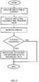
- Fig. 2is a flow diagram showing the principal actions carried out by the web server 14, which is responsive to an event timetable stored and updated in the database 19.
- an IP content providerinterfaces with the web server for creating IP content and associating therewith calendar and program data indicating dates, times and channels in respect of which the IP content is to be streamed to the customer premises.
- the web server 14monitors events, which are triggered in known manner causing the web server 14 to extract from the database 19 pre-stored IP content for streaming over the Internet 15 to the TV-Internet Integration Box 16, where it is processed as described below with reference to Fig. 3 of the drawings.
- Fig. 3is a flow diagram showing the principal actions carried out by the TV-Internet Integration Box 16.
- the subscriberselects what kind of IP content he wishes to receive and in respect of which program details, such as icons and/or textual data, are to be displayed together with the TV broadcast data.
- program detailssuch as icons and/or textual data
- the subscriberis able to program the TV-Internet Integration Box 16 in much the same way that a video cassette recorder is programmed so as to store in the memory 26 a timetable indicating what type of IP data is to be displayed and when. The timetable is updated as and when required by the subscriber.
- the TV-Internet Integration Box 16is adapted to check the timetable periodically and to filter out incoming IP content that is either of a type that is not required or that is broadcast during an unauthorized time window. By such means, an additional layer of authorization may be provided to that stored in the database 19 for access by the web server 14, thus allowing pre-fetching of IP content and storage in the memory 26 of the TV-Internet Integration Box 16.
- the TV-Internet Integration Box 16Upon detecting a matching event, corresponding to received IP content that is of interest to the subscriber, the TV-Internet Integration Box 16 overlays the matched IP content with the current broadcast and displays the new integrated video on the subscriber's TV set 17.
- the matched informationmay be an icon that indicates to the subscriber that an Internet movie is currently being broadcast; or it may be an advertisement or information related to the TV program being broadcast.
- the subscribercan respond to the overlaid data using a remote control unit, described below with reference to Fig. 6 of the drawings, which is programmed to interact with the displayed icon or other data that is overlaid on the TV broadcast.
- the displayed IP contentmay optionally contain textual information advising the subscriber to press a particular button on the remote control unit.
- buttons on the remote control unitmay be color-coded and the icon may be colored so as to indicate to the subscriber which color-coded button to press for selection of the corresponding IP content.
- the TV-Internet Integration Box 16receives the signal from the remote control unit and changes the priorities for use with the Picture-in-Picture (PIP) technique to display the TV broadcast in a reduced window and to show the other media, i.e. the IP content, in an enlarged window.
- the IP contentcan be a custom designed web page for TV, or a game or advertisement movie or any other information placed on the matched record.
- PIP techniquesare known per se and allow a video or graphics image to be inserted on top of a movie clip and to be positioned and sized. An Effect In and Effect Out may be used to fade or move the inserted video to the screen.
- the bulk of the IP content e.g. corresponding to a moviemay be rendered transparent so as to provide a transparent window through which an icon e.g. relating to the movie is visible.
- the video content of the TV broadcastis displayed in one window and the IP content in another window. Since the bulk of the IP content is transparent it will remain invisible to the subscriber, while the icon (or text) will be visible since it is opaque.
- the attributesmay simply be reversed so as to hide the icon while displaying the movie or other content.
- the TV broadcastmay be re-sized either to display it in a minimized window it the case that it is to be suppressed altogether, or to display it superimposed on the IP content so that both are visible at the same time in different, possibly overlapping, windows.
- Fig. 4is a flow diagram showing the principal actions carried out by an IP content provider such as an advertiser for creating IP content for overlaying by the TV-Internet Integration Box with a broadcast TV signal.
- an IP content providersuch as an advertiser for creating IP content for overlaying by the TV-Internet Integration Box with a broadcast TV signal.
- the advertiserdesigns an advertisement and sends it together with a request to a web site link via the Internet or off-line as required.
- the IP contentis intended for display on a low resolution TV screen
- any textual information that forms part of the IP contentis formatted so as to be legible when displayed on lower resolution TV screens.
- thisrequires reducing the quantity of textual information to a minimum and sizing any text so that it is legible.
- a web advertiserwill wish to create an on-line advertisement based on an existing web page. In such case, it may be necessary to reduce and resize any textual information so as to comply with these requirements.
- the requestspecifies calendar and program data as explained above, which the web site operator checks for availability and type, defining to which group of users it belongs. If the required time slots are available for the requested channels, the site operator confirms the request and forwards the request to the web control room for final confirmation. On confirming the request, a status flag of the advertisement is changed so as to indicate that the advertisement is awaiting final confirmation from the web control room. At the web control room the advertisement is checked for content by human evaluators who either approve or reject the advertisement content and, in the case of rejection, may provide reasons therefor. If the advertisement (or other IP content) is approved by the web control center, its status is set to "approved" and the web control center bills the customer and the web site operator adds the advertisement and the scheduling information to the database 19.
- the customer who is billedis typically the advertiser but may be any entity that is identified by a digital signature associated with the advertisement. If either of the requests for approval is rejected the status of the advertisement is set to "rejected" and the web control room informs the advertiser of the grounds for rejection, allowing the advertiser to change the request and re-send to the web site operator.
- the web servermay be adapted to display to the advertiser the occupied timetable and suggest new timetable. Only those advertisements whose status flag indicates that they are approved by the web control room are actually available for transmission. The time slot and channel information associated with any advertisement that is not so approved remain available for other advertisements and will be shown as available to another advertiser who attempts to schedule an advertisement. Only when the advertisement is actually approved by the web site operator and its status is updated accordingly, are the transmission time and channel locked for use by other users.
- the IP packet datamay optionally be associated with predefined user-profiles that are also stored in the database 19 so that the advertisement or other IP data is sent only to specific TV-Internet Integration Boxes.
- user-profilesmay be configured by the advertiser or by the user.
- the inventionallows supplementary or complementary program content to be associated with a TV broadcast, while providing the facility to view the supplementary program content only to specific subscribers, according to their user-profiles.
- the inventionallows sign language to be associated with a TV broadcast for the hard of hearing. It is known to display sign language in a corner of the screen, but since this is usually done indiscriminately it also apt to disturb the majority of viewers who do not need the sign language.
- the inventionmay be used to avoid this by conveying the sign language as IP content separate from main TV broadcast and allowing subscribers to register for a "sign language" service so that only registered subscribers receive the IP content. IP content files corresponding to sign language to be associated with different TV broadcasts are created as explained above, and stored in the database 19 together with user-profile data indicating which subscribers are registered to obtain the service.
- the user-profile datamay contain data that further refines the target audience, such as categories of TV program alongside which the sign language is to be displayed.
- the user-profile datamay further contain geographical data or language data that allows sign language corresponding to a target language to be conveyed to specific audiences.
- a TV programcan be accompanied by a sign language overlay that is customized to a target language depending on the location of the IP target address or the language requested by the subscriber on registering for the service.
- Fig. 5is a block diagram showing the functionality of the TV-Internet Integration Box 16 shown in Fig. 1 .
- the TV-Internet Integration Box 16comprises a first input 21 for receiving first data corresponding to a TV broadcast signal, typically being a cable TV signal and a second input 22 for receiving respective second data corresponding to IP packet data.
- the IP packet datamay optionally be downloaded to specific TV-Internet Integration Boxes in accordance with predefined user-profiles associated with IP packet data and stored in the database 19.
- a combiner unit 23is coupled to the first and second inputs for combining the first data and the second data to form a combined video signal.
- a video output 24is coupled to the combiner unit 23 for conveying the combined video signal to a TV set in a user premises.
- the TV setmay be a conventional TV having a relatively low resolution screen for displaying a first image corresponding to the first data and having superimposed thereon a second image corresponding to the second data.
- itcan be a computer having a video card for displaying a combined video image on a high resolution display monitor.
- the combiner unit 23is shown coupled to a processing unit 25 although in practice it may be implemented in software by the processing unit 25.
- a memory 26is coupled to the processing unit 25 for storing program data, such as profiles and program timetables etc. so as to allow the processing unit 25 to filter incoming IP content according to pre-defined profiles and other selection data.
- the processing unit 25is also coupled to a user interface 27 that allows the subscriber to program the TV-Internet Integration Box 16 and store the program data in the memory 26.
- An IR receiver 28is adapted to receive IR commands from a remote control unit described below with reference to Fig. 6 and is coupled to a decoder 29, which decodes a received IR signal and feeds it to the processing unit 25 for further processing.
- Fig. 6is a block diagram showing the functionality of a remote control unit 30 for interfacing with the TV-Internet Integration Box 16 shown in Fig. 5 .
- the remote control unit 30includes a processing unit 31 coupled to a user interface 32, typically having a keypad or pushbuttons for program selection and setting as well as other functions.
- the user interface 32is coupled to an encoder 33 which is responsive to a pressed key or key combination for producing a corresponding IR signal that is transmitted by an IR transmitter 34 to the TV-Internet Integration Box 16 for receipt by the IR receiver 28 thereof.
- the keysmay be color coded in correspondence with prearranged colors of commonly displayed icons, so that pressing on a specific key activates the displayed icon of the same color.
- at least some of the keysmay be covered with transfers depicting commonly displayed icons, whereupon the appropriate keys or button for activating each icon are easily recognized.
- the keysmay also be programmed so that depressing the same key more than once automatically re-sizes the windows containing the TV broadcast and the Internet broadcast.
- Fig. 7ashows the default situation where a TV screen 40 displays a conventional TV broadcast in a window 41 that is sized to occupy the whole area of the TV screen 40 and will be referred to as the primary window.
- IP icons 42, 43 and 44each of which points to a different IP content that is streamed from a respective web site of known address.
- the IP content corresponding theretois displayed within a small window 45 (referred to as the secondary window) that is contained within the primary window 41 as shown in Fig. 7a .
- each keyoperates as a three-way toggle that switches between three different display modes.
- the second data containing display information for the iconsalso contains data that informs the TV-Internet Integration Box 16 on which channel or channels the associated IP content is to be streamed and at what times.
- the second dataalso specifies the web site where the IP content is located. This is summarized in the following table: Table I: Second data - definition Icon image Channel Time Website of IP content ICON.GIF 2; 23 19:30; 21:30 www.AB.com/adverts/123.htm
- the second data depicted in Table I aboveshows that the icon image is contained in a file called ICON.GIF and that the IP content relating thereto is to be streamed on channels 2 and 23 at times 19:30 and 21:30, these being the start times.
- the end timesare determined by the duration of the IP content to be streamed, which is downloaded from a web site whose name is shown in the table and is contained in the second data.
- the second datais downloaded from the web server 14 whose web site address is known to the TV-Internet Integration Box 16.
- the processing unit 25is programmed to access the web server 14 periodically and download current program data. For example, once every 2 to 3 hours the TV-Internet Integration Box 16 may automatically access the web server 14 to download the second data corresponding current program data for the next 3 hours as formatted according to Table I.
- the downloaded informationis stored locally in the memory 26 of the TV-Internet Integration Box 16. This allows the TV-Internet Integration Box 16 to pre-fetch IP content relating to all the currently displayed icons and to store the data relating thereto in the memory 26 thus obviating the need to access the web site of a selected icon for the purpose of downloading IP selected content. Since this carries the overhead of web access and downloading of data, which can be cumbersome particularly if there is insufficient bandwidth, pre-fetching in this manner ensures that initial IP content data will be immediately available on selection of one of the icons.
- Fig. 8is a flow diagram showing the principal actions carried out by the TV-Internet Integration Box when pre-fetching a digital broadcast signal.
- the TV-Internet Integration Box 16periodically accesses the web server 14 and downloads current program data, constituting the second data. It then extracts from the current program data the image files of the current icons and stores them in the memory 26. In like manner, it extracts the web sites of the IP content corresponding to the currently displayed icons and then accesses these sites to pre-fetch the respective IP content, which it likewise stores in the memory 26.
- the TV-Internet Integration Box 16opens a secondary window 45 within the primary window 41, reads from the memory 26 the pre-fetched IP content and displays it in the secondary window 45.
- the TV-Internet Integration Boxmay be at least partially implemented by a suitably programmed computer.
- the inventioncontemplates a computer program being readable by a computer for executing the method of the invention.
- the inventionfurther contemplates a machine-readable memory tangibly embodying a program of instructions executable by the machine for executing the method of the invention.
Landscapes
- Engineering & Computer Science (AREA)
- Multimedia (AREA)
- Signal Processing (AREA)
- Databases & Information Systems (AREA)
- Marketing (AREA)
- Business, Economics & Management (AREA)
- Human Computer Interaction (AREA)
- Software Systems (AREA)
- Astronomy & Astrophysics (AREA)
- General Physics & Mathematics (AREA)
- Physics & Mathematics (AREA)
- Computer Security & Cryptography (AREA)
- Two-Way Televisions, Distribution Of Moving Picture Or The Like (AREA)
Description
- This invention relates to the broadcast of audio/video content over the TV infrastructure and Internet.
- With the proliferation of cable TV and the high bandwidth currently available for the Internet, which promises to increase even more in the near future, Internet TV is fast becoming a viable alternative to regular and cable TV broadcast channels. Moreover, Internet TV is not subject to the government licensing laws required by cable and broadcast TV channels and thus offers programs that may not be obtainable using regular and cable TV broadcast channels.
- It is not uncommon for Internet broadcasters to offer near DVD-quality movies that can be viewed either using video streaming or downloaded to the hard disk of a subscriber's computer for viewing "off-line". The video quality of such movies is vastly superior to that obtainable on a regular TV set, owing to the high resolution associated with computer displays that cannot presently be matched by TV screens. However, this is not particularly troublesome where only pictures are displayed; but it becomes a problem when textual information is displayed that is formatted for high resolution computer monitors since the text is then barely legible when displayed on lower resolution TV screens. Thus, if a regular TV set is used to display Internet content that is rich in text, the resulting display quality is poor.
- It would therefore be a significant benefit to users of low resolution displays such as TV screens, to be able to watch regular and cable TV broadcasts and to integrate with Internet content on demand. In particular, it would be desirable to provide such a user with a visual and legible indication when viewing a regular or TV broadcast of available Internet movies or other programs and allow him to use the displayed indication to integrate with a desired Internet broadcast.
- These requirements have been only partially addressed in the art.
WO 00/08855 US 2002/0093594 (Kikinis ) entitled"Method and system for identifying addressing data within a television presentation" illustrates inFig. 5 the common connection of TV and Internet to a set-top box.US 6,606,746 to OpenTV, Inc. entitled"Interactive television system and method for displaying a graphical user interface using insert pictures" discloses interactive television having a compressed background picture and one or more compressed insert pictures commonly connected to a TV-Internet Integration box. The compressed insert pictures represent items of a GUI. The local system i.e. computer "pastes" the insert pictures into the background image.US 6,130,898 to Bell Atlantic Network Services, Inc., entitled "Simulcasting digital video programs for broadcast and interactive services" teaches an interactive TV system where TV broadcast data is merged with Internet data. To this end, public wireless packet data network is combined with a broadband digital broadcast network at a plurality of transmitter sites. Customer premises receiving systems include a receiving antenna and one or more digital entertainment terminals. The terminal includes a channel selector and digital receiver for capturing a digital transport stream from a selected channel. A processor converts selected program information from the transport stream for presentation, e.g. via a television set. The terminal also includes a CPU controlling the operation of the channel selector and the processor in response to user inputs.US 2002/0088004 (corresponding toWO0219689 published Mar. 7, 2002 US 2004/0107437 (Herrington et al.) published June 3, 2004 discloses systems and methods for providing enhanced advertising and merchandising opportunities. Advertisements may be provided for passive programming such as television programs, commercials, pay-per-view programs, passive video products, or other suitable passive programming. Interactive advertisements may be provided in interactive applications such as interactive television program guides, web browsers, home shopping applications, operating systems, or other suitable interactive applications. It appears that composite video data is prepared off-line by what is referred to as a main facility and then conveyed to a subscriber's TV set.- None of these references appears to disclose the ability to merge broadcast TV signals with IP packet data at a customer site, specifically in such a manner that a conventional TV set is able to display Internet program selection data while viewing a TV broadcast program and to use the selected data to select an Internet channel, such as a movie, for display on the TV set instead of the TV broadcast program.
WO 02/19689 A US 2001/0003212 discloses a system that communicates video information including television content associated with a plurality of channels and ancillary information. Information may be transmitted with the ancillary information that is indicative of the type of content included in the ancillary information.US 2002/0056129 discloses an interactive television trigger having a time attribute value that indicates a future time when the trigger is to be executed. In situations where the trigger cannot be sent to the receiver unit at the desired time of trigger execution (for example, due to limited available bandwidth of a communication channel to the receiver unit), the trigger is sent prior to the future time. The receiver unit then executes the trigger on the receiver unit at the future time as indicated by the time attribute.- The public standard ATVEF (Advanced Television Enhancement Forum) Specification describes delivery mechanisms for interactive television experiences using existing Internet technologies.
- It is therefore an object of the present invention to provide a TV-Internet Integration Box having the ability to merge broadcast TV signals with IP packet data at a customer site.
- It is a further object that such a TV-Internet Integration Box permits a TV set connected thereto to display Internet program selection data while viewing a TV broadcast program and to use the selected data to select an Internet movie for display instead of the TV broadcast program.
- These objectives are realized in accordance with the attached independent claims. Various embodiments of the present invention are specified by the dependent claims.
- In order to understand the invention and to see how it may be carried out in practice, a preferred embodiment will now be described, by way of non-limiting example only, with reference to the accompanying drawings, in which:
Fig. 1 is pictorial representation showing a TV-Internet Integration Box according to the invention connected to a mixed broadcast network for combining Internet and broadcast TV signals;Fig. 2 is a flow diagram showing the principal actions carried out by the web server shown inFig. 1 ;Fig. 3 is a flow diagram showing the principal actions carried out by the TV-Internet Integration Box shown inFig. 1 ;Fig. 4 is a flow diagram showing the principal actions carried out by an IP content provider such as an advertiser for creating IP content for overlaying by the TV-Internet Integration Box with a broadcast TV signal;Fig. 5 is a block diagram showing the functionality of the TV-Internet Integration Box shown inFig. 1 ;Fig. 6 is a block diagram showing the functionality of a remote control unit for interfacing with the TV-Internet Integration Box shown inFig. 5 ;Figs. 7a,7b and 7c are pictorial representations showing a TV set during different stages of receiving and displaying combined Internet and broadcast TV signals; andFig. 8 is a flow diagram showing the principal actions carried out by the TV-Internet Integration Box when pre-fetching a digital broadcast signal.Fig. 1 is pictorial representation showing a mixedbroadcast network 10 having aCable TV Box 11 coupled to asatellite 12 and aCable TV transmitter 13 for receiving a cable TV broadcast signal (constituting first data). An Internet broadcast signal comprising IP packet data (constituting second data) is streamed from aweb server 14 via the Internet 15 (constituting a digital data communications network) to a TV-Internet Integration Box 16 for display on aTV set 17 coupled thereto. TheTV set 17 may be constituted by a computer having a video card and a high resolution display monitor. However, the principal benefit of the invention is obtained when a regular TV set having low resolution is used, since such a configuration has not so far been used to integrate Internet programs with conventional TV broadcasts in the manner proposed by the invention. The TV-Internet Integration Box 16 is connected to theCable TV Box 11 for combining the broadcast TV signals received by theCable TV Box 11 with the IP packet data broadcast via theInternet 15. Also shown is anadvertiser 18 having a computer coupled to theInternet 15 for downloading advertising content to theweb server 14 for storage in adatabase 19 and atelephone 20 coupled to the TV-Internet Integration Box 16 for feeding telephony signals to the TV-Internet Integration Box 16, which combines the received telephony signals with video data received from theCable TV Box 11 and/or theInternet 15.- The
advertiser 18 typically pays for specific time slots and for one or more specific channels during which his advertisement will be broadcast. Thus, in addition to the advertising content which is prepared and then stored on theweb server 14 in known manner, theadvertiser 18 also specifies when the advertisement is to be broadcast and on which TV channel or channels. By such means, a sports advertiser can request time during the interval of a football match to broadcast a commercial, while a toy advertiser would obviously prefer to broadcast a commercial during a children's TV program. Different time slots may be charged out at different rates depending on the ratings associated with the associated TV program. After selecting one or more time slots, the advertisement content as well as the selected time slots and program data are stored in thedatabase 19 accessed by theweb server 14. Fig. 2 is a flow diagram showing the principal actions carried out by theweb server 14, which is responsive to an event timetable stored and updated in thedatabase 19. To this end, an IP content provider interfaces with the web server for creating IP content and associating therewith calendar and program data indicating dates, times and channels in respect of which the IP content is to be streamed to the customer premises. Once this is done, theweb server 14 monitors events, which are triggered in known manner causing theweb server 14 to extract from thedatabase 19 pre-stored IP content for streaming over theInternet 15 to the TV-Internet Integration Box 16, where it is processed as described below with reference toFig. 3 of the drawings.Fig. 3 is a flow diagram showing the principal actions carried out by the TV-Internet Integration Box 16. In accordance with one embodiment of the invention, the subscriber selects what kind of IP content he wishes to receive and in respect of which program details, such as icons and/or textual data, are to be displayed together with the TV broadcast data. For example, a subscriber may wish to block certain types of program material or may wish to receive details thereof only during limited hours, for example when the children are asleep. To this end, the subscriber is able to program the TV-Internet Integration Box 16 in much the same way that a video cassette recorder is programmed so as to store in the memory 26 a timetable indicating what type of IP data is to be displayed and when. The timetable is updated as and when required by the subscriber. The TV-Internet Integration Box 16 is adapted to check the timetable periodically and to filter out incoming IP content that is either of a type that is not required or that is broadcast during an unauthorized time window. By such means, an additional layer of authorization may be provided to that stored in thedatabase 19 for access by theweb server 14, thus allowing pre-fetching of IP content and storage in thememory 26 of the TV-Internet Integration Box 16. Upon detecting a matching event, corresponding to received IP content that is of interest to the subscriber, the TV-Internet Integration Box 16 overlays the matched IP content with the current broadcast and displays the new integrated video on the subscriber'sTV set 17. For example, the matched information may be an icon that indicates to the subscriber that an Internet movie is currently being broadcast; or it may be an advertisement or information related to the TV program being broadcast.- The subscriber can respond to the overlaid data using a remote control unit, described below with reference to
Fig. 6 of the drawings, which is programmed to interact with the displayed icon or other data that is overlaid on the TV broadcast. To this end, the displayed IP content may optionally contain textual information advising the subscriber to press a particular button on the remote control unit. Alternatively, buttons on the remote control unit may be color-coded and the icon may be colored so as to indicate to the subscriber which color-coded button to press for selection of the corresponding IP content. If the subscriber responds to the overlaid data by pressing a button on the remote control unit, the TV-Internet Integration Box 16 receives the signal from the remote control unit and changes the priorities for use with the Picture-in-Picture (PIP) technique to display the TV broadcast in a reduced window and to show the other media, i.e. the IP content, in an enlarged window. The IP content can be a custom designed web page for TV, or a game or advertisement movie or any other information placed on the matched record. PIP techniques are knownper se and allow a video or graphics image to be inserted on top of a movie clip and to be positioned and sized. An Effect In and Effect Out may be used to fade or move the inserted video to the screen. In accordance with one such technique, the bulk of the IP content e.g. corresponding to a movie may be rendered transparent so as to provide a transparent window through which an icon e.g. relating to the movie is visible. The video content of the TV broadcast is displayed in one window and the IP content in another window. Since the bulk of the IP content is transparent it will remain invisible to the subscriber, while the icon (or text) will be visible since it is opaque. On selecting the displayed icon, the attributes may simply be reversed so as to hide the icon while displaying the movie or other content. At the same time, the TV broadcast may be re-sized either to display it in a minimized window it the case that it is to be suppressed altogether, or to display it superimposed on the IP content so that both are visible at the same time in different, possibly overlapping, windows. Fig. 4 is a flow diagram showing the principal actions carried out by an IP content provider such as an advertiser for creating IP content for overlaying by the TV-Internet Integration Box with a broadcast TV signal. Thus, the advertiser designs an advertisement and sends it together with a request to a web site link via the Internet or off-line as required. Since the IP content is intended for display on a low resolution TV screen, any textual information that forms part of the IP content is formatted so as to be legible when displayed on lower resolution TV screens. Generally, this requires reducing the quantity of textual information to a minimum and sizing any text so that it is legible. Often, a web advertiser will wish to create an on-line advertisement based on an existing web page. In such case, it may be necessary to reduce and resize any textual information so as to comply with these requirements.- The request specifies calendar and program data as explained above, which the web site operator checks for availability and type, defining to which group of users it belongs. If the required time slots are available for the requested channels, the site operator confirms the request and forwards the request to the web control room for final confirmation. On confirming the request, a status flag of the advertisement is changed so as to indicate that the advertisement is awaiting final confirmation from the web control room. At the web control room the advertisement is checked for content by human evaluators who either approve or reject the advertisement content and, in the case of rejection, may provide reasons therefor. If the advertisement (or other IP content) is approved by the web control center, its status is set to "approved" and the web control center bills the customer and the web site operator adds the advertisement and the scheduling information to the
database 19. The customer who is billed is typically the advertiser but may be any entity that is identified by a digital signature associated with the advertisement. If either of the requests for approval is rejected the status of the advertisement is set to "rejected" and the web control room informs the advertiser of the grounds for rejection, allowing the advertiser to change the request and re-send to the web site operator. Optionally, in such case the web server may be adapted to display to the advertiser the occupied timetable and suggest new timetable. Only those advertisements whose status flag indicates that they are approved by the web control room are actually available for transmission. The time slot and channel information associated with any advertisement that is not so approved remain available for other advertisements and will be shown as available to another advertiser who attempts to schedule an advertisement. Only when the advertisement is actually approved by the web site operator and its status is updated accordingly, are the transmission time and channel locked for use by other users. - The IP packet data may optionally be associated with predefined user-profiles that are also stored in the
database 19 so that the advertisement or other IP data is sent only to specific TV-Internet Integration Boxes. Such user-profiles may be configured by the advertiser or by the user. Thus, for example, the invention allows supplementary or complementary program content to be associated with a TV broadcast, while providing the facility to view the supplementary program content only to specific subscribers, according to their user-profiles. - Thus, by way of non-limiting example, the invention allows sign language to be associated with a TV broadcast for the hard of hearing. It is known to display sign language in a corner of the screen, but since this is usually done indiscriminately it also apt to disturb the majority of viewers who do not need the sign language. The invention may be used to avoid this by conveying the sign language as IP content separate from main TV broadcast and allowing subscribers to register for a "sign language" service so that only registered subscribers receive the IP content. IP content files corresponding to sign language to be associated with different TV broadcasts are created as explained above, and stored in the
database 19 together with user-profile data indicating which subscribers are registered to obtain the service. The user-profile data may contain data that further refines the target audience, such as categories of TV program alongside which the sign language is to be displayed. The user-profile data may further contain geographical data or language data that allows sign language corresponding to a target language to be conveyed to specific audiences. By such means, a TV program can be accompanied by a sign language overlay that is customized to a target language depending on the location of the IP target address or the language requested by the subscriber on registering for the service. Fig. 5 is a block diagram showing the functionality of the TV-Internet Integration Box 16 shown inFig. 1 . Thus, the TV-Internet Integration Box 16 comprises afirst input 21 for receiving first data corresponding to a TV broadcast signal, typically being a cable TV signal and asecond input 22 for receiving respective second data corresponding to IP packet data. The IP packet data may optionally be downloaded to specific TV-Internet Integration Boxes in accordance with predefined user-profiles associated with IP packet data and stored in thedatabase 19. Acombiner unit 23 is coupled to the first and second inputs for combining the first data and the second data to form a combined video signal. Avideo output 24 is coupled to thecombiner unit 23 for conveying the combined video signal to a TV set in a user premises. The TV set may be a conventional TV having a relatively low resolution screen for displaying a first image corresponding to the first data and having superimposed thereon a second image corresponding to the second data. Alternatively, it can be a computer having a video card for displaying a combined video image on a high resolution display monitor.- The
combiner unit 23 is shown coupled to aprocessing unit 25 although in practice it may be implemented in software by theprocessing unit 25. Amemory 26 is coupled to theprocessing unit 25 for storing program data, such as profiles and program timetables etc. so as to allow theprocessing unit 25 to filter incoming IP content according to pre-defined profiles and other selection data. Theprocessing unit 25 is also coupled to auser interface 27 that allows the subscriber to program the TV-Internet Integration Box 16 and store the program data in thememory 26. AnIR receiver 28 is adapted to receive IR commands from a remote control unit described below with reference toFig. 6 and is coupled to adecoder 29, which decodes a received IR signal and feeds it to theprocessing unit 25 for further processing. Fig. 6 is a block diagram showing the functionality of aremote control unit 30 for interfacing with the TV-Internet Integration Box 16 shown inFig. 5 . Theremote control unit 30 includes aprocessing unit 31 coupled to auser interface 32, typically having a keypad or pushbuttons for program selection and setting as well as other functions. Theuser interface 32 is coupled to anencoder 33 which is responsive to a pressed key or key combination for producing a corresponding IR signal that is transmitted by anIR transmitter 34 to the TV-Internet Integration Box 16 for receipt by theIR receiver 28 thereof.- As noted above, the keys may be color coded in correspondence with prearranged colors of commonly displayed icons, so that pressing on a specific key activates the displayed icon of the same color. Alternatively, at least some of the keys may be covered with transfers depicting commonly displayed icons, whereupon the appropriate keys or button for activating each icon are easily recognized.
- The keys may also be programmed so that depressing the same key more than once automatically re-sizes the windows containing the TV broadcast and the Internet broadcast. For example,
Fig. 7a shows the default situation where aTV screen 40 displays a conventional TV broadcast in awindow 41 that is sized to occupy the whole area of theTV screen 40 and will be referred to as the primary window. Also shown areIP icons remote control unit 30 that corresponds to theicon 42, the IP content corresponding thereto is displayed within a small window 45 (referred to as the secondary window) that is contained within theprimary window 41 as shown inFig. 7a . Theicons remote control unit 30. On pressing a key a second time in succession, the IP content is re-sized so that itswindow 45 occupies substantially the whole area of the screen as shown inFig. 7c . On pressing the key a third time in succession, the situation reverts to the default shown inFig. 7a where theprimary window 41 containing the TV broadcast occupies the whole area of theTV screen 40. Thus, each key operates as a three-way toggle that switches between three different display modes. - The second data containing display information for the icons also contains data that informs the TV-
Internet Integration Box 16 on which channel or channels the associated IP content is to be streamed and at what times. The second data also specifies the web site where the IP content is located. This is summarized in the following table:Table I: Second data -definition Icon image Channel Time Website of IP content ICON.GIF 2; 23 19:30; 21:30 www.AB.com/adverts/123.htm - Thus, the second data depicted in Table I above shows that the icon image is contained in a file called ICON.GIF and that the IP content relating thereto is to be streamed on
channels 2 and 23 at times 19:30 and 21:30, these being the start times. The end times are determined by the duration of the IP content to be streamed, which is downloaded from a web site whose name is shown in the table and is contained in the second data. - The second data is downloaded from the
web server 14 whose web site address is known to the TV-Internet Integration Box 16. According to the present invention, theprocessing unit 25 is programmed to access theweb server 14 periodically and download current program data. For example, once every 2 to 3 hours the TV-Internet Integration Box 16 may automatically access theweb server 14 to download the second data corresponding current program data for the next 3 hours as formatted according to Table I. The downloaded information is stored locally in thememory 26 of the TV-Internet Integration Box 16. This allows the TV-Internet Integration Box 16 to pre-fetch IP content relating to all the currently displayed icons and to store the data relating thereto in thememory 26 thus obviating the need to access the web site of a selected icon for the purpose of downloading IP selected content. Since this carries the overhead of web access and downloading of data, which can be cumbersome particularly if there is insufficient bandwidth, pre-fetching in this manner ensures that initial IP content data will be immediately available on selection of one of the icons. Fig. 8 is a flow diagram showing the principal actions carried out by the TV-Internet Integration Box when pre-fetching a digital broadcast signal. Thus, the TV-Internet Integration Box 16 periodically accesses theweb server 14 and downloads current program data, constituting the second data. It then extracts from the current program data the image files of the current icons and stores them in thememory 26. In like manner, it extracts the web sites of the IP content corresponding to the currently displayed icons and then accesses these sites to pre-fetch the respective IP content, which it likewise stores in thememory 26. On selection of an icon, the TV-Internet Integration Box 16 opens asecondary window 45 within theprimary window 41, reads from thememory 26 the pre-fetched IP content and displays it in thesecondary window 45.- It will be understood that the TV-Internet Integration Box according to the invention may be at least partially implemented by a suitably programmed computer. Likewise, the invention contemplates a computer program being readable by a computer for executing the method of the invention. The invention further contemplates a machine-readable memory tangibly embodying a program of instructions executable by the machine for executing the method of the invention.
Claims (16)
- A method for generating at a user's premises a combined video signal consisting of a TV broadcast signal constituting a first data and overlay display information constituting a second data, the method comprising:(a) providing a combiner unit (23) at the user's premises, wherein:the combiner unit (23) is connected to a first input (21) for receiving said first data,the combiner unit is connected to a video output (24) at the user's premises for conveying the combined video signal to a TV set, andthe combiner unit (23) is connected to a second input (22) for receiving said second data from an Internet data source providing said overlay display information over the Internet (15),characterized in that:the combiner unit (23) is connected to a processor unit (25) which periodically accesses the Internet data source for downloading said second data which are then stored in a memory (26);said overlay display information includes at least:a Web link indicating a website where an Internet content that is associated with said overlay display information is stored,an icon indicative of the content associated with said overlay display information, andoverlay trigger criteria including at least a channel information and a time information defining on which channel or channels of said TV broadcast signal the associated Internet content is to be streamed and at what times; andthe method further comprises:
(b) processing at the user's premises said overlay display information and generating at the user's premises a corresponding combined video signal upon detecting that said overlay trigger criteria are met, wherein generating the combined video signal includes:generating at the user's premises a first display window (41) including at least a first portion corresponding to said TV broadcast signals and a second portion overlaid over said first portion and corresponding at least to said icon, andassociating the Web link with said second portion of the first display window (41) thereby allowing a user to cause the combiner unit (23) to retrieve said Internet content, generate a second video display window (45) including at least a portion which corresponds to said Internet content, and provide the second video display window (45) within the first display window (41) as output. - The method according to claim 1, wherein said overlay display information is received at the user premises according to a pre-stored user profile.
- The method according to any one of claims 1 to 2, further including:receiving a command from a user at said user premises; andresponsive to said command, resizing said second video display window (41).
- The method according to any one of the preceding claims, wherein the overlay display information includes one or more icons and for each of said one or more icons said overlay display information includes a respective Web link indicating a web site where the Internet content associated with the respective icon is stored and respective overlay trigger criteria, and wherein generating said second portion overlaid over said first portion further includes generating a second portion for each of said one or more icons.
- The method according to claim 4, further including: prefetching from said website and storing in said memory (26) the Internet content corresponding to said one or more icons currently displayed.
- The method according to any one of claims 1 to 5, wherein the Internet content is supplementary or complementary to the first data.
- The method according to any one of claims 1 to 6, wherein said icon indicates to the user that Internet content is currently being broadcast.
- The method according to claim 7, including selecting specific Internet content by pressing a color-coded button on a remote control unit (30) in accordance with a color of said icon.
- The method according to any one of claims 1 to 6, wherein said overlay display information contains textual information advising the user to press a particular button on the remote control unit (30).
- A TV-Internet Integration Box (16) for generating at a user's premises a combined video signal consisting of a TV broadcast signal constituting a first data and overlay display information constituting a second data, the TV-Internet Integration Box comprising:a combiner unit (23) at a user's premises coupled to a first input (21) for receiving said first data,the combiner unit is connected to a video output (24) for conveying the combined video signal to a TV set, whereinthe combiner unit (23) is connected to a second input (22) for receiving said second data from an Internet data source providing said overlay display information over the Internet (15),characterized in that:the combiner unit (23) is connected to a processor unit (25) which periodically accesses the Internet data source for downloading said second data which are then stored in a memory (26);said overlay display information includes at least:a Web link indicating a website where an Internet content that is associated with said overlay display information is stored,an icon indicative of the content associated with said overlay display information, andoverlay trigger criteria including at least a channel information and a time information defining on which channel or channels of said TV broadcast signal the associated Internet content is to be streamed and at what times; andwherein said combiner unit (23) is configured to process at the user's premises said overlay display information and to generate at the user's premises a corresponding combined video signal upon detecting that said criteria are met, wherein said combiner unit (23) is further configured, when generating the combined video signal, to:generate at the user's premises a first display window (41) including at least a first portion corresponding to said TV broadcast signal and a second portion overlaid over said first portion and corresponding at least to said icon or program details, andassociate the Web link with said second portion of the first display window (41) thereby allowing a user to cause the combiner unit (23) to retrieve said Internet content, generate a second video display window (45) including at least a portion which corresponds to said Internet content, and provide the second video display window (45) as output.
- The TV-Internet Integration Box according to claim 10, wherein said overlay display information is received at the user premises according to a pre-stored user-profile.
- The TV-Internet Integration Box according to claim 10 or 11, further configured to receive a command from a remote control unit (30) at said user premises; and to resize said second video display window (41) in response to said command.
- The TV-Internet Integration Box according to any one of claims 10 to 12, wherein the overlay display information includes one or more icons and for each of said one or more icons said overlay display information includes a respective Web link indicating a web site where the Internet content associated with the respective icon is stored and respective overlay trigger criteria, and
wherein the combiner unit (23) is further configured, when generating said second portion overlaid over said first portion, to generate a second portion for each of said one or more icons. - The TV-Internet Integration Box according to claim 13, further configured to prefetch from said website and store in said memory (26) the Internet content corresponding to said one or more icons currently displayed.
- The TV-Internet Integration Box according to any one of claims 10 to 14, wherein said icon indicates to the user that digital data from Internet content is currently being broadcast.
- The TV-Internet Integration Box according to any one of claims 10 to 15, wherein the icon is colored so as to allow user selection of a specific Internet content by pressing a color-coded button on a remote control unit (30) in accordance with a color of said icon.
Priority Applications (1)
| Application Number | Priority Date | Filing Date | Title |
|---|---|---|---|
| EP19203153.2AEP3629575A1 (en) | 2005-01-11 | 2005-01-11 | Method and apparatus for facilitating toggling between internet and tv broadcasts |
Applications Claiming Priority (1)
| Application Number | Priority Date | Filing Date | Title |
|---|---|---|---|
| PCT/IL2005/000035WO2006075313A1 (en) | 2005-01-11 | 2005-01-11 | Method and apparatus for facilitating toggling between internet and tv broadcasts |
Related Child Applications (2)
| Application Number | Title | Priority Date | Filing Date |
|---|---|---|---|
| EP19203153.2ADivisionEP3629575A1 (en) | 2005-01-11 | 2005-01-11 | Method and apparatus for facilitating toggling between internet and tv broadcasts |
| EP19203153.2ADivision-IntoEP3629575A1 (en) | 2005-01-11 | 2005-01-11 | Method and apparatus for facilitating toggling between internet and tv broadcasts |
Publications (2)
| Publication Number | Publication Date |
|---|---|
| EP1847127A1 EP1847127A1 (en) | 2007-10-24 |
| EP1847127B1true EP1847127B1 (en) | 2020-08-05 |
Family
ID=34981541
Family Applications (2)
| Application Number | Title | Priority Date | Filing Date |
|---|---|---|---|
| EP19203153.2AWithdrawnEP3629575A1 (en) | 2005-01-11 | 2005-01-11 | Method and apparatus for facilitating toggling between internet and tv broadcasts |
| EP05703078.5AExpired - LifetimeEP1847127B1 (en) | 2005-01-11 | 2005-01-11 | Method and apparatus for facilitating toggling between internet and tv broadcasts |
Family Applications Before (1)
| Application Number | Title | Priority Date | Filing Date |
|---|---|---|---|
| EP19203153.2AWithdrawnEP3629575A1 (en) | 2005-01-11 | 2005-01-11 | Method and apparatus for facilitating toggling between internet and tv broadcasts |
Country Status (7)
| Country | Link |
|---|---|
| US (7) | USRE50399E1 (en) |
| EP (2) | EP3629575A1 (en) |
| JP (1) | JP2008527897A (en) |
| CN (1) | CN100508593C (en) |
| CA (1) | CA2592508C (en) |
| TW (1) | TWI283131B (en) |
| WO (1) | WO2006075313A1 (en) |
Families Citing this family (45)
| Publication number | Priority date | Publication date | Assignee | Title |
|---|---|---|---|---|
| US7917130B1 (en) | 2003-03-21 | 2011-03-29 | Stratosaudio, Inc. | Broadcast response method and system |
| EP1728374B1 (en)* | 2004-02-03 | 2009-10-28 | SanDisk Secure Content Solutions, Inc. | Protection of digital data content |
| KR20060132005A (en)* | 2004-03-25 | 2006-12-20 | 소프트뱅크비비 가부시키가이샤 | Information delivery system and information delivery method |
| GB2419975A (en)* | 2004-11-09 | 2006-05-10 | Nokia Corp | Auxiliary content handling |
| US8107010B2 (en)* | 2005-01-05 | 2012-01-31 | Rovi Solutions Corporation | Windows management in a television environment |
| US9294729B2 (en)* | 2006-01-19 | 2016-03-22 | At&T Intellectual Property I, L.P. | System and method for providing content over a television network |
| WO2008018049A1 (en)* | 2006-08-10 | 2008-02-14 | Tvngo Ltd. | Method and apparatus for facilitating a universal tv control to emulate mouse cursor controls of internet tv |
| US7861260B2 (en) | 2007-04-17 | 2010-12-28 | Almondnet, Inc. | Targeted television advertisements based on online behavior |
| US8566164B2 (en)* | 2007-12-31 | 2013-10-22 | Intent IQ, LLC | Targeted online advertisements based on viewing or interacting with television advertisements |
| US7688861B2 (en)* | 2007-04-27 | 2010-03-30 | Hewlett-Packard Development Company, L.P. | Media channel switching |
| KR20090025056A (en)* | 2007-09-05 | 2009-03-10 | 삼성전자주식회사 | Method of outputting data from broadcast receiving device and broadcast receiving device |
| WO2009111515A2 (en)* | 2008-03-04 | 2009-09-11 | Wms Gaming, Inc. | Controlling wagering transactions for multi-provider game content |
| US20110009188A1 (en)* | 2007-11-20 | 2011-01-13 | Adiraju Srinivyasa M | Controlling wagering transactions for multi-provider game content |
| KR20090062681A (en)* | 2007-12-13 | 2009-06-17 | 삼성전자주식회사 | GI provision method and broadcasting receiver |
| US8631448B2 (en) | 2007-12-14 | 2014-01-14 | Stratosaudio, Inc. | Systems and methods for scheduling interactive media and events |
| US20090177736A1 (en) | 2007-12-14 | 2009-07-09 | Christensen Kelly M | Systems and methods for outputting updated media |
| US8166081B2 (en) | 2008-02-05 | 2012-04-24 | Stratosaudio, Inc. | System and method for advertisement transmission and display |
| WO2009115765A1 (en)* | 2008-03-19 | 2009-09-24 | Hewlett-Packard Development Company, L.P. | Media content preparation and delivery |
| US20110289528A1 (en)* | 2008-10-02 | 2011-11-24 | Yang Pan | Dedicated button of remote control for advertisement delivery using interactive television |
| WO2010056924A1 (en)* | 2008-11-13 | 2010-05-20 | Wms Gaming, Inc. | Presenting content in wagering game systems |
| TWI454145B (en)* | 2009-02-03 | 2014-09-21 | Univ Nat Cheng Kung | A method and program product for the rapid movement of channels for Internet TV |
| IL198607A (en)* | 2009-05-06 | 2016-07-31 | Golobrodsky Oleg | Device and method for providing services to a user of a tv set |
| KR20110029553A (en)* | 2009-09-16 | 2011-03-23 | 삼성전자주식회사 | Display device and driving method |
| US8407756B2 (en) | 2009-09-22 | 2013-03-26 | At&T Intellectual Property I, L.P. | Systems and methods for remote web query and image selection exchange to video screen |
| DE102010009738A1 (en)* | 2010-03-01 | 2011-09-01 | Institut für Rundfunktechnik GmbH | Arrangement for translating spoken language into a sign language for the deaf |
| US10271090B2 (en)* | 2010-07-30 | 2019-04-23 | Richard Winter | Dynamic video content apparatuses, systems and methods |
| TW201207634A (en)* | 2010-08-09 | 2012-02-16 | Hon Hai Prec Ind Co Ltd | System and method for importing information of images |
| BR112013026829A2 (en)* | 2011-04-22 | 2017-07-04 | Samsung Electronics Co Ltd | receiver, dataflow processing method, method of transmitting a data stream, and method of transmitting dataflow |
| US20130055313A1 (en)* | 2011-08-31 | 2013-02-28 | Sony Corporation | Method, computer program, reception apparatus, and information providing apparatus for accessing content from a plurality of content sources |
| ITBO20120053A1 (en)* | 2012-02-06 | 2013-08-07 | Cenacchi Federica | DECENTRALIZED AND MULTI-LAYERING ARCHITECTURE OF DISTRIBUTION AND DISTRIBUTION OF DIGITAL INTERACTIVE CONTENT INTEGRATED TO TELEVISION DIFFUSION |
| JP5362065B2 (en)* | 2012-03-30 | 2013-12-11 | 株式会社東芝 | Television equipment |
| USD711902S1 (en)* | 2012-08-03 | 2014-08-26 | Microsoft Corporation | Display screen with graphical user interface |
| USD723057S1 (en) | 2012-08-07 | 2015-02-24 | Microsoft Corporation | Display screen with animated graphical user interface |
| CN102917265A (en)* | 2012-10-25 | 2013-02-06 | 深圳创维-Rgb电子有限公司 | Information browsing method and system based on network television |
| US8713600B2 (en) | 2013-01-30 | 2014-04-29 | Almondnet, Inc. | User control of replacement television advertisements inserted by a smart television |
| TWI521959B (en) | 2013-12-13 | 2016-02-11 | 財團法人工業技術研究院 | Method and system of searching and collating video files, method for establishing a semantic group, and program storage medium therefor |
| US9749701B2 (en) | 2014-04-17 | 2017-08-29 | Microsoft Technology Licensing, Llc | Intelligent routing of notifications to grouped devices |
| KR101699337B1 (en)* | 2014-08-20 | 2017-01-24 | 전자부품연구원 | Ultra high definition video data transceiving system based on scalable high efficiency video coding |
| US9990028B2 (en)* | 2014-10-03 | 2018-06-05 | Verizon Patent And Licensing Inc. | System and method for providing live augmented reality content |
| US20160212492A1 (en)* | 2015-01-21 | 2016-07-21 | Rovi Guides, Inc. | Systems and methods for automatically modifying functionality of an actuator |
| CN106331794A (en)* | 2015-06-29 | 2017-01-11 | 联想(北京)有限公司 | Information processing method and electronic device |
| US9628839B1 (en) | 2015-10-06 | 2017-04-18 | Arris Enterprises, Inc. | Gateway multi-view video stream processing for second-screen content overlay |
| CN106973322A (en) | 2015-12-09 | 2017-07-21 | 财团法人工业技术研究院 | Multi-media content cross-screen synchronization device and method, playing device and server |
| JP6186457B2 (en)* | 2016-01-19 | 2017-08-23 | ヤフー株式会社 | Information display program, information display device, information display method, and distribution device |
| US10284900B2 (en)* | 2016-03-15 | 2019-05-07 | Sony Corporation | Multiview as an application for physical digital media |
Citations (2)
| Publication number | Priority date | Publication date | Assignee | Title |
|---|---|---|---|---|
| US20010003212A1 (en)* | 1999-10-29 | 2001-06-07 | Jerilyn L. Marler | Identifying ancillary information associated with an audio/video program |
| US20020056129A1 (en)* | 1999-10-05 | 2002-05-09 | Dean J. Blackketter | Trigger having a time attribute |
Family Cites Families (38)
| Publication number | Priority date | Publication date | Assignee | Title |
|---|---|---|---|---|
| NZ259147A (en)* | 1992-12-09 | 1997-05-26 | Discovery Communicat Inc | Network controller for cable television |
| JPH08202636A (en) | 1995-01-27 | 1996-08-09 | Global Manag Kk | Intelligent peripheral equipment device having general-purpose input file generating function |
| US5822324A (en) | 1995-03-16 | 1998-10-13 | Bell Atlantic Network Services, Inc. | Simulcasting digital video programs for broadcast and interactive services |
| US6240555B1 (en) | 1996-03-29 | 2001-05-29 | Microsoft Corporation | Interactive entertainment system for presenting supplemental interactive content together with continuous video programs |
| WO1997043855A1 (en)* | 1996-05-16 | 1997-11-20 | Kabushiki Kaisha Infocity | Method for transmitting and displaying information and device for displaying information |
| JP3649433B2 (en)* | 1996-05-16 | 2005-05-18 | 株式会社インフォシティ | Information display device and information transmission display method |
| US5801747A (en)* | 1996-11-15 | 1998-09-01 | Hyundai Electronics America | Method and apparatus for creating a television viewer profile |
| US6510557B1 (en)* | 1997-01-03 | 2003-01-21 | Texas Instruments Incorporated | Apparatus for the integration of television signals and information from an information service provider |
| US20020007493A1 (en)* | 1997-07-29 | 2002-01-17 | Laura J. Butler | Providing enhanced content with broadcast video |
| US6606746B1 (en) | 1997-10-16 | 2003-08-12 | Opentv, Inc. | Interactive television system and method for displaying a graphical user interface using insert pictures |
| IL141104A0 (en) | 1998-07-27 | 2002-02-10 | Webtv Networks Inc | Remote computer access |
| CN1317201A (en) | 1998-08-05 | 2001-10-10 | 联合视频制品公司 | System and method for synchronizing TV-related product content and internet-delivered information |
| US6182287B1 (en) | 1999-02-04 | 2001-01-30 | Thomson Licensing S.A. | Preferred service management system for a multimedia video decoder |
| US6351270B1 (en)* | 1999-03-01 | 2002-02-26 | Sony Corporation | Miniature video in the guide logo |
| US6136898A (en) | 1999-06-15 | 2000-10-24 | Marathon Ashland Petroleum Llc | Unblown ethylene-vinyl acetate copolymer treated asphalt and its method of preparation |
| US6760324B1 (en) | 1999-09-10 | 2004-07-06 | Array Telecom Corporation | Method, system, and computer program product for providing voice over the internet communication |
| TW516309B (en)* | 1999-12-10 | 2003-01-01 | United Video Properties Inc | Features for use with advanced set-top applications on interactive television systems |
| US20020124255A1 (en) | 1999-12-10 | 2002-09-05 | United Video Properties, Inc. | Systems and methods for coordinating interactive and passive advertisement and merchandising opportunities |
| US7340457B1 (en)* | 1999-12-16 | 2008-03-04 | Texas Instruments Incorporated | Apparatus and method to facilitate the customization of television content with supplemental data |
| US6892359B1 (en) | 2000-02-18 | 2005-05-10 | Xside Corporation | Method and system for controlling a complementary user interface on a display surface |
| US7096489B2 (en) | 2000-08-28 | 2006-08-22 | Sony Corporation | System and method for interactive television |
| EP2028859A1 (en) | 2000-08-28 | 2009-02-25 | Sony Electronics, Inc. | System for interactive television |
| JP2002135676A (en)* | 2000-10-27 | 2002-05-10 | Canon Inc | Television signal receiving apparatus, its processing method and recording medium |
| US7456902B2 (en) | 2000-12-04 | 2008-11-25 | Jlb Ventures, Llc | Method and system for identifying addressing data within a television presentation |
| JP4765182B2 (en)* | 2001-01-19 | 2011-09-07 | ソニー株式会社 | Interactive television communication method and interactive television communication client device |
| US20030030652A1 (en)* | 2001-04-17 | 2003-02-13 | Digeo, Inc. | Apparatus and methods for advertising in a transparent section in an interactive content page |
| JP2004007323A (en)* | 2001-06-11 | 2004-01-08 | Matsushita Electric Ind Co Ltd | Television broadcast receiver |
| JP2003018575A (en)* | 2001-07-03 | 2003-01-17 | Matsushita Electric Ind Co Ltd | Television receiver, information acquisition system, and information acquisition method |
| US7631327B2 (en) | 2001-08-08 | 2009-12-08 | Accenture Global Services Gmbh | Enhanced custom content television |
| JP2003069950A (en)* | 2001-08-29 | 2003-03-07 | Mitsubishi Electric Corp | Commercial providing system and commercial providing method |
| EP1317143A1 (en)* | 2001-11-28 | 2003-06-04 | Deutsche Thomson-Brandt Gmbh | Recording of broadcasting enhancement services |
| JP2003323370A (en)* | 2002-04-30 | 2003-11-14 | Hitachi Software Eng Co Ltd | Personal www proxy program, personal information terminal and content prefetch method of personal information terminal |
| CN1469644A (en)* | 2002-07-17 | 2004-01-21 | 众频科技股份有限公司 | Method and system for combining IP website broadcast and on-demand video signal |
| US20040064835A1 (en) | 2002-09-26 | 2004-04-01 | International Business Machines Corporation | System and method for content based on-demand video media overlay |
| EP1582038A4 (en) | 2003-01-07 | 2008-11-12 | Home Box Office Inc | Integrated media viewing environment |
| US8281339B1 (en)* | 2004-01-12 | 2012-10-02 | United Video Properties, Inc. | Customizable flip and browse overlays in an interactive television system |
| US7546902B2 (en) | 2005-11-07 | 2009-06-16 | Larry Victor Schwertner | Personnel lift apparatus |
| US20100085483A1 (en)* | 2008-10-02 | 2010-04-08 | Yang Pan | Dedicated button of remote control for advertisement delivery using interactive television |
- 2005
- 2005-01-11USUS17/714,917patent/USRE50399E1/enactiveActive
- 2005-01-11EPEP19203153.2Apatent/EP3629575A1/ennot_activeWithdrawn
- 2005-01-11WOPCT/IL2005/000035patent/WO2006075313A1/enactiveApplication Filing
- 2005-01-11JPJP2007550930Apatent/JP2008527897A/enactivePending
- 2005-01-11USUS11/794,825patent/US8132220B2/ennot_activeCeased
- 2005-01-11EPEP05703078.5Apatent/EP1847127B1/ennot_activeExpired - Lifetime
- 2005-01-11CACA2592508Apatent/CA2592508C/ennot_activeExpired - Lifetime
- 2005-04-26TWTW094113241Apatent/TWI283131B/ennot_activeIP Right Cessation
- 2005-08-25CNCNB2005100966234Apatent/CN100508593C/ennot_activeExpired - Fee Related
- 2011
- 2011-12-23USUS13/336,239patent/US9392339B2/enactiveActive
- 2011-12-23USUS13/336,189patent/US9407969B2/ennot_activeCeased
- 2011-12-23USUS13/336,219patent/US9124945B2/enactiveActive
- 2015
- 2015-11-25USUS14/951,990patent/US9794621B2/ennot_activeExpired - Lifetime
- 2022
- 2022-07-18USUS17/867,612patent/USRE50328E1/enactiveActive
Patent Citations (2)
| Publication number | Priority date | Publication date | Assignee | Title |
|---|---|---|---|---|
| US20020056129A1 (en)* | 1999-10-05 | 2002-05-09 | Dean J. Blackketter | Trigger having a time attribute |
| US20010003212A1 (en)* | 1999-10-29 | 2001-06-07 | Jerilyn L. Marler | Identifying ancillary information associated with an audio/video program |
Also Published As
| Publication number | Publication date |
|---|---|
| CN100508593C (en) | 2009-07-01 |
| US9794621B2 (en) | 2017-10-17 |
| USRE50399E1 (en) | 2025-04-22 |
| TWI283131B (en) | 2007-06-21 |
| EP3629575A1 (en) | 2020-04-01 |
| USRE50328E1 (en) | 2025-03-04 |
| JP2008527897A (en) | 2008-07-24 |
| US20120096507A1 (en) | 2012-04-19 |
| HK1089315A1 (en) | 2006-11-24 |
| CA2592508A1 (en) | 2006-07-20 |
| US9392339B2 (en) | 2016-07-12 |
| EP1847127A1 (en) | 2007-10-24 |
| CA2592508C (en) | 2017-05-02 |
| US20080046942A1 (en) | 2008-02-21 |
| WO2006075313A1 (en) | 2006-07-20 |
| US8132220B2 (en) | 2012-03-06 |
| US9407969B2 (en) | 2016-08-02 |
| US9124945B2 (en) | 2015-09-01 |
| US20170302993A9 (en) | 2017-10-19 |
| CN1805538A (en) | 2006-07-19 |
| US20160261910A1 (en) | 2016-09-08 |
| US20120096506A1 (en) | 2012-04-19 |
| US20120096505A1 (en) | 2012-04-19 |
| TW200625960A (en) | 2006-07-16 |
Similar Documents
| Publication | Publication Date | Title |
|---|---|---|
| USRE50328E1 (en) | Forming overlays at user's premises and utilizing them for selective combinations of TV broadcast channel format material and IP-format material | |
| US10395273B2 (en) | Computer program product for providing selective advertising to a television viewer using an interactive display | |
| US9197938B2 (en) | Contextual display of information with an interactive user interface for television | |
| JP3958354B2 (en) | Improved set-top terminals for cable TV distribution systems | |
| EP1097583B1 (en) | Navigation system for a multichannel digital television system | |
| US7320134B1 (en) | System and method for cable operator control over enhanced programming | |
| US20110265115A1 (en) | Displaying Enhanced Content Information on a Remote Control Unit | |
| JP2024166253A (en) | Method of providing programs and video content | |
| KR100843303B1 (en) | System and method for providing selective advertisement in video on demand system | |
| JP7687873B2 (en) | Distribution System | |
| HK1089315B (en) | Method and apparatus for facilitating toggling between internet and tv broadcasts | |
| HK1033517B (en) | Navigation system for a multichannel digital television system |
Legal Events
| Date | Code | Title | Description |
|---|---|---|---|
| PUAI | Public reference made under article 153(3) epc to a published international application that has entered the european phase | Free format text:ORIGINAL CODE: 0009012 | |
| 17P | Request for examination filed | Effective date:20070813 | |
| RBV | Designated contracting states (corrected) | Designated state(s):AT BE BG CH CY CZ DE DK EE ES FI FR GB GR HU IE IS IT LI LT LU MC NL PL PT RO SE SI SK TR | |
| DAX | Request for extension of the european patent (deleted) | ||
| 17Q | First examination report despatched | Effective date:20111115 | |
| GRAP | Despatch of communication of intention to grant a patent | Free format text:ORIGINAL CODE: EPIDOSNIGR1 | |
| STAA | Information on the status of an ep patent application or granted ep patent | Free format text:STATUS: GRANT OF PATENT IS INTENDED | |
| RIC1 | Information provided on ipc code assigned before grant | Ipc:H04N 21/4782 20110101ALI20190528BHEP Ipc:H04N 21/44 20110101ALI20190528BHEP Ipc:H04N 21/61 20110101ALI20190528BHEP Ipc:H04N 21/854 20110101ALI20190528BHEP Ipc:H04N 21/443 20110101ALI20190528BHEP Ipc:H04N 21/438 20110101ALI20190528BHEP Ipc:H04N 7/173 20110101AFI20190528BHEP Ipc:H04N 21/433 20110101ALI20190528BHEP Ipc:H04N 21/81 20110101ALI20190528BHEP Ipc:H04N 21/431 20110101ALI20190528BHEP Ipc:H04N 21/643 20110101ALI20190528BHEP Ipc:H04N 21/462 20110101ALI20190528BHEP | |
| INTG | Intention to grant announced | Effective date:20190621 | |
| GRAS | Grant fee paid | Free format text:ORIGINAL CODE: EPIDOSNIGR3 | |
| GRAA | (expected) grant | Free format text:ORIGINAL CODE: 0009210 | |
| STAA | Information on the status of an ep patent application or granted ep patent | Free format text:STATUS: THE PATENT HAS BEEN GRANTED | |
| REG | Reference to a national code | Ref country code:DE Ref legal event code:R081 Ref document number:602005056939 Country of ref document:DE Owner name:TVNGO LTD., IL Free format text:FORMER OWNER: TVNGO LTD., RAANANA, IL | |
| AK | Designated contracting states | Kind code of ref document:B1 Designated state(s):AT BE BG CH CY CZ DE DK EE ES FI FR GB GR HU IE IS IT LI LT LU MC NL PL PT RO SE SI SK TR | |
| REG | Reference to a national code | Ref country code:GB Ref legal event code:FG4D | |
| REG | Reference to a national code | Ref country code:CH Ref legal event code:EP | |
| REG | Reference to a national code | Ref country code:AT Ref legal event code:REF Ref document number:1300382 Country of ref document:AT Kind code of ref document:T Effective date:20200815 | |
| REG | Reference to a national code | Ref country code:DE Ref legal event code:R096 Ref document number:602005056939 Country of ref document:DE | |
| REG | Reference to a national code | Ref country code:IE Ref legal event code:FG4D | |
| REG | Reference to a national code | Ref country code:LT Ref legal event code:MG4D | |
| REG | Reference to a national code | Ref country code:NL Ref legal event code:MP Effective date:20200805 | |
| REG | Reference to a national code | Ref country code:AT Ref legal event code:MK05 Ref document number:1300382 Country of ref document:AT Kind code of ref document:T Effective date:20200805 | |
| PG25 | Lapsed in a contracting state [announced via postgrant information from national office to epo] | Ref country code:SE Free format text:LAPSE BECAUSE OF FAILURE TO SUBMIT A TRANSLATION OF THE DESCRIPTION OR TO PAY THE FEE WITHIN THE PRESCRIBED TIME-LIMIT Effective date:20200805 Ref country code:FI Free format text:LAPSE BECAUSE OF FAILURE TO SUBMIT A TRANSLATION OF THE DESCRIPTION OR TO PAY THE FEE WITHIN THE PRESCRIBED TIME-LIMIT Effective date:20200805 Ref country code:LT Free format text:LAPSE BECAUSE OF FAILURE TO SUBMIT A TRANSLATION OF THE DESCRIPTION OR TO PAY THE FEE WITHIN THE PRESCRIBED TIME-LIMIT Effective date:20200805 Ref country code:AT Free format text:LAPSE BECAUSE OF FAILURE TO SUBMIT A TRANSLATION OF THE DESCRIPTION OR TO PAY THE FEE WITHIN THE PRESCRIBED TIME-LIMIT Effective date:20200805 Ref country code:BG Free format text:LAPSE BECAUSE OF FAILURE TO SUBMIT A TRANSLATION OF THE DESCRIPTION OR TO PAY THE FEE WITHIN THE PRESCRIBED TIME-LIMIT Effective date:20201105 Ref country code:GR Free format text:LAPSE BECAUSE OF FAILURE TO SUBMIT A TRANSLATION OF THE DESCRIPTION OR TO PAY THE FEE WITHIN THE PRESCRIBED TIME-LIMIT Effective date:20201106 Ref country code:ES Free format text:LAPSE BECAUSE OF FAILURE TO SUBMIT A TRANSLATION OF THE DESCRIPTION OR TO PAY THE FEE WITHIN THE PRESCRIBED TIME-LIMIT Effective date:20200805 Ref country code:PT Free format text:LAPSE BECAUSE OF FAILURE TO SUBMIT A TRANSLATION OF THE DESCRIPTION OR TO PAY THE FEE WITHIN THE PRESCRIBED TIME-LIMIT Effective date:20201207 | |
| PG25 | Lapsed in a contracting state [announced via postgrant information from national office to epo] | Ref country code:IS Free format text:LAPSE BECAUSE OF FAILURE TO SUBMIT A TRANSLATION OF THE DESCRIPTION OR TO PAY THE FEE WITHIN THE PRESCRIBED TIME-LIMIT Effective date:20201205 Ref country code:NL Free format text:LAPSE BECAUSE OF FAILURE TO SUBMIT A TRANSLATION OF THE DESCRIPTION OR TO PAY THE FEE WITHIN THE PRESCRIBED TIME-LIMIT Effective date:20200805 Ref country code:PL Free format text:LAPSE BECAUSE OF FAILURE TO SUBMIT A TRANSLATION OF THE DESCRIPTION OR TO PAY THE FEE WITHIN THE PRESCRIBED TIME-LIMIT Effective date:20200805 | |
| PG25 | Lapsed in a contracting state [announced via postgrant information from national office to epo] | Ref country code:RO Free format text:LAPSE BECAUSE OF FAILURE TO SUBMIT A TRANSLATION OF THE DESCRIPTION OR TO PAY THE FEE WITHIN THE PRESCRIBED TIME-LIMIT Effective date:20200805 Ref country code:EE Free format text:LAPSE BECAUSE OF FAILURE TO SUBMIT A TRANSLATION OF THE DESCRIPTION OR TO PAY THE FEE WITHIN THE PRESCRIBED TIME-LIMIT Effective date:20200805 Ref country code:DK Free format text:LAPSE BECAUSE OF FAILURE TO SUBMIT A TRANSLATION OF THE DESCRIPTION OR TO PAY THE FEE WITHIN THE PRESCRIBED TIME-LIMIT Effective date:20200805 Ref country code:CZ Free format text:LAPSE BECAUSE OF FAILURE TO SUBMIT A TRANSLATION OF THE DESCRIPTION OR TO PAY THE FEE WITHIN THE PRESCRIBED TIME-LIMIT Effective date:20200805 | |
| REG | Reference to a national code | Ref country code:DE Ref legal event code:R097 Ref document number:602005056939 Country of ref document:DE | |
| PLBE | No opposition filed within time limit | Free format text:ORIGINAL CODE: 0009261 | |
| STAA | Information on the status of an ep patent application or granted ep patent | Free format text:STATUS: NO OPPOSITION FILED WITHIN TIME LIMIT | |
| PG25 | Lapsed in a contracting state [announced via postgrant information from national office to epo] | Ref country code:SK Free format text:LAPSE BECAUSE OF FAILURE TO SUBMIT A TRANSLATION OF THE DESCRIPTION OR TO PAY THE FEE WITHIN THE PRESCRIBED TIME-LIMIT Effective date:20200805 | |
| 26N | No opposition filed | Effective date:20210507 | |
| PG25 | Lapsed in a contracting state [announced via postgrant information from national office to epo] | Ref country code:IT Free format text:LAPSE BECAUSE OF FAILURE TO SUBMIT A TRANSLATION OF THE DESCRIPTION OR TO PAY THE FEE WITHIN THE PRESCRIBED TIME-LIMIT Effective date:20200805 | |
| PG25 | Lapsed in a contracting state [announced via postgrant information from national office to epo] | Ref country code:SI Free format text:LAPSE BECAUSE OF FAILURE TO SUBMIT A TRANSLATION OF THE DESCRIPTION OR TO PAY THE FEE WITHIN THE PRESCRIBED TIME-LIMIT Effective date:20200805 Ref country code:MC Free format text:LAPSE BECAUSE OF FAILURE TO SUBMIT A TRANSLATION OF THE DESCRIPTION OR TO PAY THE FEE WITHIN THE PRESCRIBED TIME-LIMIT Effective date:20200805 | |
| REG | Reference to a national code | Ref country code:CH Ref legal event code:PL | |
| PG25 | Lapsed in a contracting state [announced via postgrant information from national office to epo] | Ref country code:LU Free format text:LAPSE BECAUSE OF NON-PAYMENT OF DUE FEES Effective date:20210111 | |
| REG | Reference to a national code | Ref country code:BE Ref legal event code:MM Effective date:20210131 | |
| PG25 | Lapsed in a contracting state [announced via postgrant information from national office to epo] | Ref country code:LI Free format text:LAPSE BECAUSE OF NON-PAYMENT OF DUE FEES Effective date:20210131 Ref country code:CH Free format text:LAPSE BECAUSE OF NON-PAYMENT OF DUE FEES Effective date:20210131 | |
| PG25 | Lapsed in a contracting state [announced via postgrant information from national office to epo] | Ref country code:IE Free format text:LAPSE BECAUSE OF NON-PAYMENT OF DUE FEES Effective date:20210111 | |
| PG25 | Lapsed in a contracting state [announced via postgrant information from national office to epo] | Ref country code:BE Free format text:LAPSE BECAUSE OF NON-PAYMENT OF DUE FEES Effective date:20210131 | |
| PG25 | Lapsed in a contracting state [announced via postgrant information from national office to epo] | Ref country code:HU Free format text:LAPSE BECAUSE OF FAILURE TO SUBMIT A TRANSLATION OF THE DESCRIPTION OR TO PAY THE FEE WITHIN THE PRESCRIBED TIME-LIMIT; INVALID AB INITIO Effective date:20050111 Ref country code:CY Free format text:LAPSE BECAUSE OF FAILURE TO SUBMIT A TRANSLATION OF THE DESCRIPTION OR TO PAY THE FEE WITHIN THE PRESCRIBED TIME-LIMIT Effective date:20200805 | |
| PGFP | Annual fee paid to national office [announced via postgrant information from national office to epo] | Ref country code:DE Payment date:20240119 Year of fee payment:20 Ref country code:GB Payment date:20240119 Year of fee payment:20 | |
| PGFP | Annual fee paid to national office [announced via postgrant information from national office to epo] | Ref country code:FR Payment date:20240124 Year of fee payment:20 | |
| PG25 | Lapsed in a contracting state [announced via postgrant information from national office to epo] | Ref country code:TR Free format text:LAPSE BECAUSE OF FAILURE TO SUBMIT A TRANSLATION OF THE DESCRIPTION OR TO PAY THE FEE WITHIN THE PRESCRIBED TIME-LIMIT Effective date:20200805 | |
| REG | Reference to a national code | Ref country code:DE Ref legal event code:R071 Ref document number:602005056939 Country of ref document:DE | |
| REG | Reference to a national code | Ref country code:GB Ref legal event code:PE20 Expiry date:20250110 | |
| PG25 | Lapsed in a contracting state [announced via postgrant information from national office to epo] | Ref country code:GB Free format text:LAPSE BECAUSE OF EXPIRATION OF PROTECTION Effective date:20250110 |