EP1844715B1 - Suture tensioning device - Google Patents
Suture tensioning deviceDownload PDFInfo
- Publication number
- EP1844715B1 EP1844715B1EP07251214.8AEP07251214AEP1844715B1EP 1844715 B1EP1844715 B1EP 1844715B1EP 07251214 AEP07251214 AEP 07251214AEP 1844715 B1EP1844715 B1EP 1844715B1
- Authority
- EP
- European Patent Office
- Prior art keywords
- suture
- insert
- shaft
- grasping member
- knotting element
- Prior art date
- Legal status (The legal status is an assumption and is not a legal conclusion. Google has not performed a legal analysis and makes no representation as to the accuracy of the status listed.)
- Not-in-force
Links
Images


Classifications
- A—HUMAN NECESSITIES
- A61—MEDICAL OR VETERINARY SCIENCE; HYGIENE
- A61B—DIAGNOSIS; SURGERY; IDENTIFICATION
- A61B17/00—Surgical instruments, devices or methods
- A61B17/04—Surgical instruments, devices or methods for suturing wounds; Holders or packages for needles or suture materials
- A—HUMAN NECESSITIES
- A61—MEDICAL OR VETERINARY SCIENCE; HYGIENE
- A61B—DIAGNOSIS; SURGERY; IDENTIFICATION
- A61B17/00—Surgical instruments, devices or methods
- A61B17/04—Surgical instruments, devices or methods for suturing wounds; Holders or packages for needles or suture materials
- A61B17/0483—Hand-held instruments for holding sutures
- A—HUMAN NECESSITIES
- A61—MEDICAL OR VETERINARY SCIENCE; HYGIENE
- A61B—DIAGNOSIS; SURGERY; IDENTIFICATION
- A61B17/00—Surgical instruments, devices or methods
- A61B17/04—Surgical instruments, devices or methods for suturing wounds; Holders or packages for needles or suture materials
- A61B17/0487—Suture clamps, clips or locks, e.g. for replacing suture knots; Instruments for applying or removing suture clamps, clips or locks
- A—HUMAN NECESSITIES
- A61—MEDICAL OR VETERINARY SCIENCE; HYGIENE
- A61B—DIAGNOSIS; SURGERY; IDENTIFICATION
- A61B17/00—Surgical instruments, devices or methods
- A61B17/04—Surgical instruments, devices or methods for suturing wounds; Holders or packages for needles or suture materials
- A61B17/0401—Suture anchors, buttons or pledgets, i.e. means for attaching sutures to bone, cartilage or soft tissue; Instruments for applying or removing suture anchors
- A61B2017/0445—Suture anchors, buttons or pledgets, i.e. means for attaching sutures to bone, cartilage or soft tissue; Instruments for applying or removing suture anchors cannulated, e.g. with a longitudinal through-hole for passage of an instrument
- A—HUMAN NECESSITIES
- A61—MEDICAL OR VETERINARY SCIENCE; HYGIENE
- A61B—DIAGNOSIS; SURGERY; IDENTIFICATION
- A61B17/00—Surgical instruments, devices or methods
- A61B17/04—Surgical instruments, devices or methods for suturing wounds; Holders or packages for needles or suture materials
- A61B17/0401—Suture anchors, buttons or pledgets, i.e. means for attaching sutures to bone, cartilage or soft tissue; Instruments for applying or removing suture anchors
- A61B2017/0446—Means for attaching and blocking the suture in the suture anchor
- A61B2017/0454—Means for attaching and blocking the suture in the suture anchor the anchor being crimped or clamped on the suture
- A—HUMAN NECESSITIES
- A61—MEDICAL OR VETERINARY SCIENCE; HYGIENE
- A61B—DIAGNOSIS; SURGERY; IDENTIFICATION
- A61B17/00—Surgical instruments, devices or methods
- A61B17/04—Surgical instruments, devices or methods for suturing wounds; Holders or packages for needles or suture materials
- A61B17/0487—Suture clamps, clips or locks, e.g. for replacing suture knots; Instruments for applying or removing suture clamps, clips or locks
- A61B2017/0488—Instruments for applying suture clamps, clips or locks
- A—HUMAN NECESSITIES
- A61—MEDICAL OR VETERINARY SCIENCE; HYGIENE
- A61B—DIAGNOSIS; SURGERY; IDENTIFICATION
- A61B17/00—Surgical instruments, devices or methods
- A61B17/04—Surgical instruments, devices or methods for suturing wounds; Holders or packages for needles or suture materials
- A61B2017/0496—Surgical instruments, devices or methods for suturing wounds; Holders or packages for needles or suture materials for tensioning sutures
Definitions
- the inventionrelates broadly to devices for tensioning a suture.
- Severe obesityis a major health risk that can decrease life expectancy and give rise to a number of other associated ailments, including the onset of cardiovascular disease, hypertension, diabetes and severe arthritis.
- a number of surgical procedurescan be performed to aid in the treatment of obesity.
- the most common procedureis a gastric restriction procedure in which opposed gastric walls are fastened or stapled together to effectively reduce the volume of a patient's stomach. More specifically, the stomach is divided by a series of staples or fasteners that extend vertically for about 2.5 inches to create a smaller stomach pouch. The outlet of the pouch into the larger stomach limits the amount of food the stomach can hold and reduces the rate of gastric emptying.
- Suture-coupled fastenersoffer the advantage of allowing the surgeon to adjust the tension of the sutures, if necessary, whereas staples must be removed and reapplied.
- the stomachis resilient and tends to stretch to return to its original state, it is often necessary to re-create the gastric restriction over time.
- Suture-coupled fastenersallow the surgeon to merely apply additional tension to the suture to keep the stomach walls together.
- suture-coupled fastenerstend to be more advantageous than staples, as the surgeon is attaching the fasteners to the opposed walls of the stomach, slack or loops of excess suture can form.
- the suturemust be tightly cinched to pull the gastric walls together so that the reduced volume of the patient's stomach can be maintained. If any slack or loose loops of suture are present, the stomach will expand and the restriction procedure will not be effective. Where additional tension is not effective to remove any slack or loops, it may be necessary to knot the excess suture to prevent it from loosening.
- European patent application publication number EP0669101A1discloses an apparatus for tensioning a suture including an elongated endoscopic body portion and a tool assembly that can be releasably disposed within the distal end of the body portion.
- the tool assemblyincludes an opening for releasably receiving a securing member at an acute angle relative to the longitudinal axis of the body portion.
- a conventional threading tool or a conventional grasping toolcan be used to engage and pull a suture material through the securing member for tensioning the suture.
- a suture tensioning devicehaving a shaft, a knotting element, and a suture grasping member.
- the knotting elementis removably coupled to a distal end of the shaft, and it is adapted to receive a suture and to lock to engage the suture.
- the suture grasping memberis movably coupled to the shaft, and it is configured to grasp a suture and pull it through the knotting element to allow the knotting element to lock and engage the suture.
- the term "knotting element” used throughout the descriptionrefers to a suture locking and engaging element.
- the suture grasping membercan have a variety of configurations.
- the suture grasping memberis slidably disposed within an inner lumen formed in the shaft and it extends through at least a portion of the knotting element.
- the suture grasping membercan include a hook formed on a distal end thereof and adapted to engage a length of suture.
- the knotting elementcan also have a variety of configurations, but in one exemplary embodiment it can include an outer sleeve and an insert receivable within the outer sleeve for locking a suture therebetween.
- the insertcan be sized to secure a suture by interference fit.
- the insertcan be compressible and the outer sleeve can be sized to compress the insert therein.
- the insert and outer sleevecan also include a locking mechanism formed therebetween and adapted to prevent the insert from backing out of the sleeve once received therein.
- the locking mechanismfor example, can include a flange formed on the insert and a complementary cam formed on the sleeve and adapted to engage the flange.
- the devicecan also include features to allow the knotting element to removably mate to the shaft.
- a distal end of the shaft and a proximal end of the knotting elementcan include a mating element adapted to removably mate the knotting element to the shaft.
- the mating elementcan be, for example, at least one pin and at least one bore adapted to receive and engage the pin.
- the pin(s)can be sized such that it is held in the bore(s) by interference fit. Various techniques can be used to release the pin(s) from the bore(s).
- the shaftcan also have a variety of configurations, but in an exemplary embodiment it can include an actuator that is adapted to advance the insert into the outer sleeve of the knotting element to lock a suture therein.
- the actuatorcan include a rod that extends through an inner lumen of the shaft.
- the distal end of the rod and a proximal end of the insertcan include a mating element adapted to removably mate the insert to the rod.
- the mating elementcan be, for example, at least one pin and at least one bore adapted to receive and engage the pin.
- the pin(s)can be sized such that it is held in the bore(s) by interference fit.
- the present disclosurealso provides a method for tensioning suture which includes engaging a length of suture with a suture grasping member coupled to a shaft.
- the suturecan have opposed ends extending through tissue.
- the suture grasping memberis then retracted to pull the suture through a knotting element coupled to a distal end of the shaft to tension the suture relative to the tissue.
- a mechanism on the shaftcan be actuated to lock the knotting element with the suture therein, and the knotting element can be released from the shaft.
- the suture grasping memberis advanced distally through at least a portion of the knotting element, and the suture is engaged with a hook formed on a distal end of the suture grasping member.
- actuating the knotting elementcan include advancing an insert into an outer sleeve of the knotting element to compress the insert and engage a suture extending therethrough.
- Releasing the knotting elementcan include releasing a proximal end of the insert from a distal end of a rod that extends through an inner lumen of the shaft.
- Releasing the knotting elementcan also include releasing a proximal end of the sleeve from a distal end of the shaft.
- the present disclosurealso provides a method of reconditioning the suture tensioning device which includes replacing or cleaning at least a portion of at least one of the shaft, knotting element, and suture grasping member.
- the methodcan further include disassembling at least a portion of the device before the step of replacing or cleaning.
- the methodcan also include reassembling at least a portion of the device after the step of replacing or cleaning.
- a suture tensioning devicehaving a shaft and a suture grasping member movably coupled to the shaft.
- the devicecan be configured to removably couple to a knotting element for locking suture extending therethrough.
- the suture grasping membercan be configured to grasp a suture and pull it through the knotting element to allow the knotting element to lock and engage the suture thereby tensioning the suture relative to tissue through which the suture extends.
- the suture tensioning devicecan be used in any procedure in which it is desirable to tension suture
- the suture tensioning deviceis particularly effective for use in tensioning slack or loops that have formed in sutures used to join opposed walls of the stomach during a gastric restriction procedure and/or for use in tensioning suture which has become loose or otherwise needs to be re-tensioned.
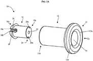
- FIGS. 1A and 1Billustrate one exemplary embodiment of a knotting element 10 that can be used with the suture tensioning devices and methods disclosed herein.
- the knotting element 10includes an outer sleeve 12 and an insert 16 receivable within the outer sleeve 12.
- the outer sleeve 12has a generally cylindrical shape with an inner lumen 14 extending between proximal and distal ends 12a, 12b thereof.
- the lumen 14preferably has a size and shape that is effective to receive the insert 16 therein, and more preferably that is effective to compress at least a portion of the insert 16 to lock a suture extending therethrough, as will be discussed below.
- the insert 16can also have a generally cylindrical shape such that it can be slidably received within the lumen 14 of the sleeve 12.
- An inner lumen 22can extend between proximal and distal ends 16a, 16b of the insert 16 for receiving a suture therethrough.
- the insert 16can also include a suture-receiving cavity 18 formed in the distal end thereof.
- the cavity 18is effective to separate or split the distal end of the insert 16 such that the opposed ends of the insert 16 can be compressed toward one another.
- at least a portion of the lumen 14has an inner diameter that is smaller than an outer diameter of a compressible portion of the insert 16 to compress the insert 16 when it is received therein.
- a distal portion of the lumen 14 in the sleeve 12has a reduced diameter that is effective to compress the distal portion of the insert 16 around the suture receiving cavity 18. As a result, a suture extending through the suture receiving cavity 18 will be engaged therein.
- FIG. 1Ba distal portion of the lumen 14 in the sleeve 12 has a reduced diameter that is effective to compress the distal portion of the insert 16 around the suture receiving cavity 18.
- the suture receiving cavity 18can include opposed ridges 18a, 18b formed therein and extending transverse to the lumen 22 in the insert 16.
- the ridges 18a, 18bcan facilitate engagement of a suture positioned therebetween and pulled into the lumen 22.
- a person skilled in the artwill appreciate that a variety of other techniques can be used to engage a suture within the insert 16 or between the insert 16 and the sleeve 12.
- the knotting element 10can also include a locking mechanism formed between the outer sleeve 12 and the insert 16 and adapted to prevent the insert 16 from backing out of the sleeve 12 once received therein.
- the locking mechanismcan have various configurations, in the illustrated embodiment the distal end 16b of the insert 16 includes a flange 26 formed thereon, and the inner lumen 14 of the sleeve includes a complementary cam 27 formed thereon and adapted to engage the flange 26 when the insert 16 is slid into the sleeve 12.
- the flange 26can engage and abut against a lip 28 of the cam 27. The lip 28 will lock the insert 16 within the sleeve 12 thereby preventing the insert 16 from backing out, i.e., sliding proximally within the sleeve 12.
- FIGS. 2A and 2Billustrate one exemplary embodiment of a suture tensioning device 20 having a shaft 30 and a suture grasping member 50 movably coupled to the shaft 30.
- a distal end 30b of the shaft 30can couple to the knotting element 10
- the suture grasping member 50is configured to grasp a suture and pull it through the knotting element 10 to allow the knotting element 10 to lock and engage the suture therein.
- the device 20can also include an actuation mechanism 46 formed on the shaft 30 that can be actuated to lock the knotting element 10 with the suture therein.
- the device 20can also include features to release the knotting element 10.
- the shaft 30 of the device 10is shown in more detail in FIG. 3 . While the shaft can have any shape and size, in the illustrated embodiment the shaft 30 has a generally elongate body in the form of a housing having proximal and distal ends 30a, 30b.
- the proximal end 30a of the shaft 30can be in the form of, or can include, a handle for grasping and manipulating the device.
- the distal end 30b of the shaft 30can removably mate to the knotting element, as will be explained below in more detail.
- An inner lumen 34can extend between the proximal and distal ends 30a, 30b of the shaft 30 for slidably receiving the suture grasping member 50, as shown in FIG. 2B .
- the length of the shaft 30can vary depending on the intended use. For example, in one exemplary embodiment, the length can be configured for endoscopic use, and all or portions of the shaft 30 can be flexible to accommodate an endoscopic procedure.
- the distal end 30b of the shaft 30is preferably adapted to removably mate to the knotting element 10. While various mating techniques can be used, in one exemplary embodiment the shaft 30 can include a mating element formed on the distal end thereof and adapted to removably mate to a complementary mating element formed on the knotting element 10. In the illustrated embodiment, the distal end 30b of the shaft 30 includes first and second pins 32a, 32b formed thereon and adapted to be slidably received within first and second bores 13a, 13b formed in the proximal end of the outer sleeve 12 of the knotting element 10.
- the pin(s) and bore(s)can have various shapes and sizes, and they can be effective to mate to one another using a snap-fit, interference fit, or other engagement technique. Exemplary pin shapes include cylindrical and hexagonal.
- the mating elementis effective to secure the sleeve 12 to the shaft 30 during the suture tensioning procedure.
- a person skilled in the artwill appreciate that other available mating techniques can be used including, for example, a magnetic engagement, a twist lock connection, or a threaded mating connection formed between the sleeve 12 of the knotting element 10 and the shaft 30.
- the shaft 30can also include an actuator adapted to advance the insert 16 into the sleeve 12 of the knotting element 10 to thereby lock a suture within the knotting element 10.
- the actuatorcan be in the form of a rod 40 that extends through the inner lumen 34 of the shaft 30.
- the rod 40can have an inner lumen 42 extending from a proximal end 40a to a distal end 40b thereof for receiving the suture grasping member, which will be described below in more detail.
- the distal end 40b of the rod 40can abut against the insert 16 of the knotting element 10 to move the insert 16.
- the rod 40can include a mating element formed on the distal end 40b thereof and adapted to removably mate to a complementary mating element formed on the insert 16 of the knotting element 10. While the mating element can have a variety of configurations, in one embodiment, the mating elements 24, 44 associated with the insert 16 and the rod 40 can be similar to the mating elements 13, 30 described above.
- the distal end 40b of the rod 40includes first and second pins 44a, 44b formed thereon and adapted to be slidably received within first and second bores 24a, 24b formed in the proximal end of the insert 16 of the knotting element 10.
- the pin(s) and bore(s)can have various shapes and sizes, and they can be effective to mate to one another using a snap-fit, interference fit, or other engagement technique. Exemplary pin shapes include cylindrical and hexagonal. As with the mating element described above, other available mating techniques can be used including, for example, a magnetic engagement, a twist lock connection, or a threaded mating connection formed between the insert 16 of the knotting element 10 and the rod 40. In use, the rod 40 can be slidably movable within the inner lumen 34 of the shaft 30 to advance the insert 16 into the sleeve 12 of the knotting element 10. Various techniques can be used to move the rod 40 relative to the shaft 30 including, for example, a handle, knob, or lever. In the embodiment shown in FIG.
- a handle 46is disposed on the proximal end 40a of the rod 40 and is positioned within a slot 36 formed in the shaft 30.
- the handle 46 on the rod 40can slidably move between a proximal position in which it retains the insert 16 within the shaft 30, and a distal position in which the insert 16 is advanced into the sleeve 12. Once the insert 16 is locked within the sleeve 12, as described above, the rod 40 can be released from the insert 16 by retracting the rod 40. The locking mechanism will prevent the insert from being retracted with the rod 40.
- the tensioning device 20can also include a suture grasping member 50 that is adapted to grasp a suture and pull the suture through the knotting element.
- the suture grasping member 50can have virtually any shape and size, but in one exemplary embodiment it has a generally elongate configuration with a proximal end 50a extending from the proximal end 30a of the shaft 30 and a distal end 50b extending through the shaft 30, rod 40, and knotting element 10.
- the proximal end 50a of the suture grasping member 50can be movably coupled to the shaft 30, and the distal most end 50b of the suture grasping member 50 can include an engagement mechanism, such as a hook 52, formed thereon for engaging a suture.
- an engagement mechanismsuch as a hook 52
- Other techniquessuch as grasping devices, can be used to engage a suture.
- a handlecan be disposed at the proximal end 50a of the suture grasping member 50 for advancing and retracting the member between a distal position in which the distal end 50b of the suture grasping member 50 extends beyond the distal end 30b of the shaft 30 to grasp a length of suture 60, and a proximal position in which the distal end 50b of the suture grasping member 50 is pulled through the knotting element 10.
- the suture grasping member 50is formed from a thin wire made of a rigid or semi-rigid material, and it has an elongate length to facilitate use in an endoscopic procedure.
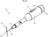
- FIGS. 6A-6Dillustrate the device 20 in use for tensioning and locking a length of suture having opposed ends extending through tissue (not shown).
- the device 20can be inserted into the body, for example, through an access port or, in a preferred embodiment, endoscopically (i.e., through a natural orifice such as the esophagus).
- the device 20can be used in conjunction with an endoscope or it can optionally include on-board image gathering and/or display optics to facilitate endoscopic viewing.
- the suture grasping member 50can be advanced such that a distal portion of the member 50 extends distally from the distal end 30b of the shaft 30 and from the knotting element 10.
- the suture grasping member 50can be manipulated to engage the suture 60 using the hook 52 formed on the distal end 50b of the member 50.
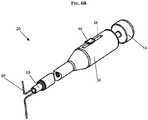
- the suture grasping member 50can be retracted by pulling the handle 54 on the proximal end of the suture grasping member 50 to pull the suture 60 through the knotting element 10 thereby tensioning the suture 60 as shown in FIG. 6B .
- the tensioncan be adjusted by moving the suture grasping member 50 to a desired position.
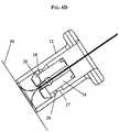
- the suture 60can then be locked within the knotting element 10 by advancing the rod 40 distally to cause the insert 16 to be advanced into and compressed by the sleeve 12, as shown in FIG. 6C .
- the flange 26 formed on the insert 16slides over the cam 27 formed on the sleeve 12. Once the flange 26 has cleared the cam 27, the flange 26 engages the lip 28 adjacent to the cam 27 and the insert 16 is prevented from backing out. The reduced diameter region in the lumen 14 will compress the insert 16 to lock the suture therein.
- the knotting element 10can be released from the device 20.
- the insert 16can be released from the rod 40 by retracting the rod 40.
- the lip 28 on the sleeve 12will engage the flange 26 on the insert 16 to retain the insert 16 within the sleeve 12.
- the sleeve 12can be released from the shaft 30 by, for example, retracting the pins 32a, 32b on the distal end 30b of the shaft 30 using an actuating mechanism (not shown) that extends through the shaft and is coupled to or integrally formed with the pins.
- the rod 40can be rotated after it is detached from the insert 16 such that the pins on the rod 40 are offset from the bores in the insert 16. The rod 40 can then be moved distally to push the knotting element 10 off of the distal end of the shaft 30.
- the sleeve 12can be threadably released from the shaft 30. A person skilled in the art will appreciate that a variety of other techniques can be used to release the knotting element.
- the suture tensioning device 20, or portions thereofcan be designed to be disposed of after a single use, or it can be designed to be used multiple times. In either case, however, the device can be reconditioned for reuse after at least one use. Reconditioning can include any combination of the steps of disassembly of the device, followed by cleaning or replacement of particular pieces, and subsequent reassembly.
- the suture tensioning device and its components shown in FIGS. 1A-5can be reconditioned after the device has been used in a medical procedure.
- the devicecan be disassembled, and any number of the particular pieces (e.g., the shaft 30, the rod 40, the knotting element 10, or the suture grasping member 50) can be selectively replaced or removed in any combination.
- the knotting elementcan be replaced by a new knotting element, while the remaining pieces are sterilized for reuse. Replacement of pieces can also include replacement of portions of particular elements.
- the devicecan be reassembled for subsequent use either at a reconditioning facility, or by a surgical team immediately prior to a surgical procedure.
- reconditioning of a suture tensioning devicecan utilize a variety of techniques for disassembly, cleaning/replacement, and reassembly. Use of such techniques, and the resulting reconditioned suture tensioning device, are all within the scope of the present application.
Landscapes
- Health & Medical Sciences (AREA)
- Life Sciences & Earth Sciences (AREA)
- Surgery (AREA)
- Heart & Thoracic Surgery (AREA)
- Engineering & Computer Science (AREA)
- Biomedical Technology (AREA)
- Nuclear Medicine, Radiotherapy & Molecular Imaging (AREA)
- Medical Informatics (AREA)
- Molecular Biology (AREA)
- Animal Behavior & Ethology (AREA)
- General Health & Medical Sciences (AREA)
- Public Health (AREA)
- Veterinary Medicine (AREA)
- Surgical Instruments (AREA)
Description
- The invention relates broadly to devices for tensioning a suture.
- Severe obesity is a major health risk that can decrease life expectancy and give rise to a number of other associated ailments, including the onset of cardiovascular disease, hypertension, diabetes and severe arthritis. A number of surgical procedures can be performed to aid in the treatment of obesity. The most common procedure is a gastric restriction procedure in which opposed gastric walls are fastened or stapled together to effectively reduce the volume of a patient's stomach. More specifically, the stomach is divided by a series of staples or fasteners that extend vertically for about 2.5 inches to create a smaller stomach pouch. The outlet of the pouch into the larger stomach limits the amount of food the stomach can hold and reduces the rate of gastric emptying.
- Some gastric restriction procedures utilize a series of fasteners that are coupled by a suture used to cinch and pull the fastened tissue together. Suture-coupled fasteners offer the advantage of allowing the surgeon to adjust the tension of the sutures, if necessary, whereas staples must be removed and reapplied. In particular, because the stomach is resilient and tends to stretch to return to its original state, it is often necessary to re-create the gastric restriction over time. Where the stomach is stapled, the original staples must be removed and replaced. Suture-coupled fasteners, on the other hand, allow the surgeon to merely apply additional tension to the suture to keep the stomach walls together.
- It may also be necessary to tension the suture during the initial gastric restriction procedure. While suture-coupled fasteners tend to be more advantageous than staples, as the surgeon is attaching the fasteners to the opposed walls of the stomach, slack or loops of excess suture can form. For the gastric restriction procedure to be successful, the suture must be tightly cinched to pull the gastric walls together so that the reduced volume of the patient's stomach can be maintained. If any slack or loose loops of suture are present, the stomach will expand and the restriction procedure will not be effective. Where additional tension is not effective to remove any slack or loops, it may be necessary to knot the excess suture to prevent it from loosening. European patent application publication number
EP0669101A1 discloses an apparatus for tensioning a suture including an elongated endoscopic body portion and a tool assembly that can be releasably disposed within the distal end of the body portion. The tool assembly includes an opening for releasably receiving a securing member at an acute angle relative to the longitudinal axis of the body portion. A conventional threading tool or a conventional grasping tool can be used to engage and pull a suture material through the securing member for tensioning the suture. - Accordingly, a need exists for methods and devices for tensioning a length of suture.
- The present invention generally provides devices for tensioning a length of suture as defined in the appended claims. A suture tensioning device is provided having a shaft, a knotting element, and a suture grasping member. The knotting element is removably coupled to a distal end of the shaft, and it is adapted to receive a suture and to lock to engage the suture. The suture grasping member is movably coupled to the shaft, and it is configured to grasp a suture and pull it through the knotting element to allow the knotting element to lock and engage the suture. Subsequently, the term "knotting element" used throughout the description refers to a suture locking and engaging element.
- The suture grasping member can have a variety of configurations. The suture grasping member is slidably disposed within an inner lumen formed in the shaft and it extends through at least a portion of the knotting element. The suture grasping member can include a hook formed on a distal end thereof and adapted to engage a length of suture.
- The knotting element can also have a variety of configurations, but in one exemplary embodiment it can include an outer sleeve and an insert receivable within the outer sleeve for locking a suture therebetween. The insert can be sized to secure a suture by interference fit. For example, the insert can be compressible and the outer sleeve can be sized to compress the insert therein. The insert and outer sleeve can also include a locking mechanism formed therebetween and adapted to prevent the insert from backing out of the sleeve once received therein. The locking mechanism, for example, can include a flange formed on the insert and a complementary cam formed on the sleeve and adapted to engage the flange.
- The device can also include features to allow the knotting element to removably mate to the shaft. In one aspect, a distal end of the shaft and a proximal end of the knotting element can include a mating element adapted to removably mate the knotting element to the shaft. The mating element can be, for example, at least one pin and at least one bore adapted to receive and engage the pin. The pin(s) can be sized such that it is held in the bore(s) by interference fit. Various techniques can be used to release the pin(s) from the bore(s).
- The shaft can also have a variety of configurations, but in an exemplary embodiment it can include an actuator that is adapted to advance the insert into the outer sleeve of the knotting element to lock a suture therein. The actuator can include a rod that extends through an inner lumen of the shaft. In one embodiment, the distal end of the rod and a proximal end of the insert can include a mating element adapted to removably mate the insert to the rod. The mating element can be, for example, at least one pin and at least one bore adapted to receive and engage the pin. In a further embodiment, the pin(s) can be sized such that it is held in the bore(s) by interference fit.
- The present disclosure also provides a method for tensioning suture which includes engaging a length of suture with a suture grasping member coupled to a shaft. The suture can have opposed ends extending through tissue. The suture grasping member is then retracted to pull the suture through a knotting element coupled to a distal end of the shaft to tension the suture relative to the tissue. A mechanism on the shaft can be actuated to lock the knotting element with the suture therein, and the knotting element can be released from the shaft. In an exemplary embodiment, the suture grasping member is advanced distally through at least a portion of the knotting element, and the suture is engaged with a hook formed on a distal end of the suture grasping member. In another aspect, actuating the knotting element can include advancing an insert into an outer sleeve of the knotting element to compress the insert and engage a suture extending therethrough. Releasing the knotting element can include releasing a proximal end of the insert from a distal end of a rod that extends through an inner lumen of the shaft. Releasing the knotting element can also include releasing a proximal end of the sleeve from a distal end of the shaft.
- The present disclosure also provides a method of reconditioning the suture tensioning device which includes replacing or cleaning at least a portion of at least one of the shaft, knotting element, and suture grasping member. The method can further include disassembling at least a portion of the device before the step of replacing or cleaning. The method can also include reassembling at least a portion of the device after the step of replacing or cleaning.
- The invention will be more fully understood from the following detailed description taken in conjunction with the accompanying drawings, in which:
FIG. 1A is a perspective view of one embodiment of a knotting element having an insert and an outer sleeve;FIG. 1B is a cross-sectional view of the knotting element shown inFIG. 1 with the insert received within the outer sleeve;FIG. 2A is a perspective view of one embodiment of a suture tensioning device showing the knotting element ofFIGS. 1A and1B coupled thereto;FIG. 2B is a cross-sectional view of the suture tensioning device and knotting element shown inFIG. 2A ;FIG. 3 is a perspective view of a shaft of the suture tensioning device shown inFIG. 2A ;FIG. 4 is a perspective view of an actuator of the suture tensioning device shown inFIG. 2A ;FIG. 5 is a perspective view of a suture grasping member of the suture tensioning device shown inFIG. 2A ;FIG. 6A is a perspective view of the suture tensioning device shown inFIG. 2A showing the suture grasping member extending through the knotting element and engaging a length of suture;FIG. 6B is a perspective view of the suture tensioning device shown inFIG. 6A showing the suture grasping member in a retracted position to pull the suture through the knotting element;FIG. 6C is a cross-sectional view of a distal portion of the suture tensioning device and the knotting element shown inFIG. 6B showing a suture locked in the knotting element;FIG. 6D is a cross-sectional view of the knotting element ofFIG. 6C detached from the suture tensioning device;- Certain exemplary embodiments will now be described to provide an overall understanding of the principles, structure, function, manufacture, and use of the devices and methods disclosed herein. One or more examples of these embodiments are illustrated in the accompanying drawings. Those skilled in the art will understand that the devices and methods specifically described herein and illustrated in the accompanying drawings are non-limiting exemplary embodiments and that the scope of the present invention is defined solely by the claims. The features illustrated or described in connection with one exemplary embodiment may be combined with features of other embodiments. Such modifications and variations are intended to be included within the scope of the present invention.
- The present invention generally provides devices and methods for tensioning a length of suture. In an exemplary embodiment, a suture tensioning device is provided having a shaft and a suture grasping member movably coupled to the shaft. The device can be configured to removably couple to a knotting element for locking suture extending therethrough. In particular, the suture grasping member can be configured to grasp a suture and pull it through the knotting element to allow the knotting element to lock and engage the suture thereby tensioning the suture relative to tissue through which the suture extends. While the suture tensioning device can be used in any procedure in which it is desirable to tension suture, the suture tensioning device is particularly effective for use in tensioning slack or loops that have formed in sutures used to join opposed walls of the stomach during a gastric restriction procedure and/or for use in tensioning suture which has become loose or otherwise needs to be re-tensioned.
- The suture tensioning devices and methods disclosed herein can be used with any device or element known in the art that is effective to knot or lock a suture therein. By way of non-limiting example,
FIGS. 1A and1B illustrate one exemplary embodiment of aknotting element 10 that can be used with the suture tensioning devices and methods disclosed herein. As shown, theknotting element 10 includes anouter sleeve 12 and aninsert 16 receivable within theouter sleeve 12. Theouter sleeve 12 has a generally cylindrical shape with aninner lumen 14 extending between proximal anddistal ends lumen 14 preferably has a size and shape that is effective to receive theinsert 16 therein, and more preferably that is effective to compress at least a portion of theinsert 16 to lock a suture extending therethrough, as will be discussed below. Theinsert 16 can also have a generally cylindrical shape such that it can be slidably received within thelumen 14 of thesleeve 12. Aninner lumen 22 can extend between proximal anddistal ends 16a, 16b of theinsert 16 for receiving a suture therethrough. As shown inFIGS. 1A and1B , theinsert 16 can also include a suture-receivingcavity 18 formed in the distal end thereof. Thecavity 18 is effective to separate or split the distal end of theinsert 16 such that the opposed ends of theinsert 16 can be compressed toward one another. In an exemplary embodiment, at least a portion of thelumen 14 has an inner diameter that is smaller than an outer diameter of a compressible portion of theinsert 16 to compress theinsert 16 when it is received therein. As shown inFIG. 1B , a distal portion of thelumen 14 in thesleeve 12 has a reduced diameter that is effective to compress the distal portion of theinsert 16 around thesuture receiving cavity 18. As a result, a suture extending through thesuture receiving cavity 18 will be engaged therein. As further shown inFIG. 1A , thesuture receiving cavity 18 can includeopposed ridges lumen 22 in theinsert 16. Theridges lumen 22. A person skilled in the art will appreciate that a variety of other techniques can be used to engage a suture within theinsert 16 or between theinsert 16 and thesleeve 12. - As further shown in
FIGS 1A and1B , theknotting element 10 can also include a locking mechanism formed between theouter sleeve 12 and theinsert 16 and adapted to prevent theinsert 16 from backing out of thesleeve 12 once received therein. While the locking mechanism can have various configurations, in the illustrated embodiment the distal end 16b of theinsert 16 includes aflange 26 formed thereon, and theinner lumen 14 of the sleeve includes acomplementary cam 27 formed thereon and adapted to engage theflange 26 when theinsert 16 is slid into thesleeve 12. In particular, as theflange 26 slides past thecam 27, theflange 26 can engage and abut against alip 28 of thecam 27. Thelip 28 will lock theinsert 16 within thesleeve 12 thereby preventing theinsert 16 from backing out, i.e., sliding proximally within thesleeve 12. - As previously indicated, the present invention provides a suture tensioning device for engaging and pulling a length of suture through a knotting element, such as knotting
element 10 shown inFIGS. 1A and1B .FIGS. 2A and2B illustrate one exemplary embodiment of asuture tensioning device 20 having ashaft 30 and asuture grasping member 50 movably coupled to theshaft 30. Adistal end 30b of theshaft 30 can couple to theknotting element 10, and thesuture grasping member 50 is configured to grasp a suture and pull it through theknotting element 10 to allow theknotting element 10 to lock and engage the suture therein. Thedevice 20 can also include anactuation mechanism 46 formed on theshaft 30 that can be actuated to lock theknotting element 10 with the suture therein. Thedevice 20 can also include features to release theknotting element 10. - The
shaft 30 of thedevice 10 is shown in more detail inFIG. 3 . While the shaft can have any shape and size, in the illustrated embodiment theshaft 30 has a generally elongate body in the form of a housing having proximal anddistal ends proximal end 30a of theshaft 30 can be in the form of, or can include, a handle for grasping and manipulating the device. Thedistal end 30b of theshaft 30 can removably mate to the knotting element, as will be explained below in more detail. Aninner lumen 34 can extend between the proximal anddistal ends shaft 30 for slidably receiving thesuture grasping member 50, as shown inFIG. 2B . The length of theshaft 30 can vary depending on the intended use. For example, in one exemplary embodiment, the length can be configured for endoscopic use, and all or portions of theshaft 30 can be flexible to accommodate an endoscopic procedure. - As indicated above, the
distal end 30b of theshaft 30 is preferably adapted to removably mate to theknotting element 10. While various mating techniques can be used, in one exemplary embodiment theshaft 30 can include a mating element formed on the distal end thereof and adapted to removably mate to a complementary mating element formed on theknotting element 10. In the illustrated embodiment, thedistal end 30b of theshaft 30 includes first andsecond pins second bores 13a, 13b formed in the proximal end of theouter sleeve 12 of theknotting element 10. The pin(s) and bore(s) can have various shapes and sizes, and they can be effective to mate to one another using a snap-fit, interference fit, or other engagement technique. Exemplary pin shapes include cylindrical and hexagonal. In use, the mating element is effective to secure thesleeve 12 to theshaft 30 during the suture tensioning procedure. A person skilled in the art will appreciate that other available mating techniques can be used including, for example, a magnetic engagement, a twist lock connection, or a threaded mating connection formed between thesleeve 12 of theknotting element 10 and theshaft 30. - As shown in
FIG. 4 , theshaft 30 can also include an actuator adapted to advance theinsert 16 into thesleeve 12 of theknotting element 10 to thereby lock a suture within theknotting element 10. In one embodiment, the actuator can be in the form of arod 40 that extends through theinner lumen 34 of theshaft 30. Therod 40 can have aninner lumen 42 extending from aproximal end 40a to adistal end 40b thereof for receiving the suture grasping member, which will be described below in more detail. Thedistal end 40b of therod 40 can abut against theinsert 16 of theknotting element 10 to move theinsert 16. In an exemplary embodiment, therod 40 can include a mating element formed on thedistal end 40b thereof and adapted to removably mate to a complementary mating element formed on theinsert 16 of theknotting element 10. While the mating element can have a variety of configurations, in one embodiment, themating elements insert 16 and therod 40 can be similar to themating elements FIG. 4 , thedistal end 40b of therod 40 includes first andsecond pins second bores insert 16 of theknotting element 10. The pin(s) and bore(s) can have various shapes and sizes, and they can be effective to mate to one another using a snap-fit, interference fit, or other engagement technique. Exemplary pin shapes include cylindrical and hexagonal. As with the mating element described above, other available mating techniques can be used including, for example, a magnetic engagement, a twist lock connection, or a threaded mating connection formed between theinsert 16 of theknotting element 10 and therod 40. In use, therod 40 can be slidably movable within theinner lumen 34 of theshaft 30 to advance theinsert 16 into thesleeve 12 of theknotting element 10. Various techniques can be used to move therod 40 relative to theshaft 30 including, for example, a handle, knob, or lever. In the embodiment shown inFIG. 4 , ahandle 46 is disposed on theproximal end 40a of therod 40 and is positioned within aslot 36 formed in theshaft 30. Thehandle 46 on therod 40 can slidably move between a proximal position in which it retains theinsert 16 within theshaft 30, and a distal position in which theinsert 16 is advanced into thesleeve 12. Once theinsert 16 is locked within thesleeve 12, as described above, therod 40 can be released from theinsert 16 by retracting therod 40. The locking mechanism will prevent the insert from being retracted with therod 40. - As shown in
FIGS. 2A ,2B and5 , thetensioning device 20 can also include asuture grasping member 50 that is adapted to grasp a suture and pull the suture through the knotting element. Thesuture grasping member 50 can have virtually any shape and size, but in one exemplary embodiment it has a generally elongate configuration with aproximal end 50a extending from theproximal end 30a of theshaft 30 and adistal end 50b extending through theshaft 30,rod 40, and knottingelement 10. Theproximal end 50a of thesuture grasping member 50 can be movably coupled to theshaft 30, and the distalmost end 50b of thesuture grasping member 50 can include an engagement mechanism, such as ahook 52, formed thereon for engaging a suture. Other techniques, such as grasping devices, can be used to engage a suture. As further shown inFIGS. 2A ,2B , and5 , a handle can be disposed at theproximal end 50a of thesuture grasping member 50 for advancing and retracting the member between a distal position in which thedistal end 50b of thesuture grasping member 50 extends beyond thedistal end 30b of theshaft 30 to grasp a length ofsuture 60, and a proximal position in which thedistal end 50b of thesuture grasping member 50 is pulled through theknotting element 10. In an exemplary embodiment, thesuture grasping member 50 is formed from a thin wire made of a rigid or semi-rigid material, and it has an elongate length to facilitate use in an endoscopic procedure. FIGS. 6A-6D illustrate thedevice 20 in use for tensioning and locking a length of suture having opposed ends extending through tissue (not shown). Thedevice 20 can be inserted into the body, for example, through an access port or, in a preferred embodiment, endoscopically (i.e., through a natural orifice such as the esophagus). Thedevice 20 can be used in conjunction with an endoscope or it can optionally include on-board image gathering and/or display optics to facilitate endoscopic viewing. Once thedevice 20 is positioned in the body proximate to suture 60 to be tensioned, thesuture grasping member 50 can be advanced such that a distal portion of themember 50 extends distally from thedistal end 30b of theshaft 30 and from theknotting element 10. As shown inFIG. 6A , thesuture grasping member 50 can be manipulated to engage thesuture 60 using thehook 52 formed on thedistal end 50b of themember 50. After engaging thesuture 60, thesuture grasping member 50 can be retracted by pulling thehandle 54 on the proximal end of thesuture grasping member 50 to pull thesuture 60 through theknotting element 10 thereby tensioning thesuture 60 as shown inFIG. 6B . The tension can be adjusted by moving thesuture grasping member 50 to a desired position. Thesuture 60 can then be locked within theknotting element 10 by advancing therod 40 distally to cause theinsert 16 to be advanced into and compressed by thesleeve 12, as shown inFIG. 6C . As theinsert 16 is slidably received by thesleeve 12, theflange 26 formed on theinsert 16 slides over thecam 27 formed on thesleeve 12. Once theflange 26 has cleared thecam 27, theflange 26 engages thelip 28 adjacent to thecam 27 and theinsert 16 is prevented from backing out. The reduced diameter region in thelumen 14 will compress theinsert 16 to lock the suture therein.- After locking the
suture 60 within theknotting element 10, theknotting element 10 can be released from thedevice 20. In one exemplary embodiment, theinsert 16 can be released from therod 40 by retracting therod 40. As described above, as therod 40 is retracted, thelip 28 on thesleeve 12 will engage theflange 26 on theinsert 16 to retain theinsert 16 within thesleeve 12. Thesleeve 12 can be released from theshaft 30 by, for example, retracting thepins distal end 30b of theshaft 30 using an actuating mechanism (not shown) that extends through the shaft and is coupled to or integrally formed with the pins. In other embodiments, therod 40 can be rotated after it is detached from theinsert 16 such that the pins on therod 40 are offset from the bores in theinsert 16. Therod 40 can then be moved distally to push theknotting element 10 off of the distal end of theshaft 30. In yet another embodiment, thesleeve 12 can be threadably released from theshaft 30. A person skilled in the art will appreciate that a variety of other techniques can be used to release the knotting element. - In another exemplary embodiment, the
suture tensioning device 20, or portions thereof, can be designed to be disposed of after a single use, or it can be designed to be used multiple times. In either case, however, the device can be reconditioned for reuse after at least one use. Reconditioning can include any combination of the steps of disassembly of the device, followed by cleaning or replacement of particular pieces, and subsequent reassembly. By way of example, the suture tensioning device and its components shown inFIGS. 1A-5 can be reconditioned after the device has been used in a medical procedure. The device can be disassembled, and any number of the particular pieces (e.g., theshaft 30, therod 40, theknotting element 10, or the suture grasping member 50) can be selectively replaced or removed in any combination. For instance, the knotting element can be replaced by a new knotting element, while the remaining pieces are sterilized for reuse. Replacement of pieces can also include replacement of portions of particular elements. Upon cleaning and/or replacement of particular parts, the device can be reassembled for subsequent use either at a reconditioning facility, or by a surgical team immediately prior to a surgical procedure. Those skilled in the art will appreciate that reconditioning of a suture tensioning device can utilize a variety of techniques for disassembly, cleaning/replacement, and reassembly. Use of such techniques, and the resulting reconditioned suture tensioning device, are all within the scope of the present application. - Persons skilled in the art will understand that the devices and methods specifically described herein and illustrated in the accompanying drawings are non-limiting exemplary embodiments. The features illustrated or described in connection with one exemplary embodiment may be combined with the features of other embodiments. Such modifications and variations are intended to be included within the scope of the present invention. As well, one skilled in the art will appreciate further features and advantages of the invention based on the above-described embodiments. Accordingly, the invention is not to be limited by what has been particularly shown and described, except as indicated by the appended claims.
Claims (9)
- A suture tensioning device (20), comprising:a shaft (30) having proximal and distal ends (30a, 30b);a suture locking and engaging element (10) removably coupled to the distal end of the shaft (30b) and adapted to receive a suture (60) and to lock to engage the suture; anda suture grasping member (50) movably coupled to the shaft (30), the suture grasping member (50) slidably disposed within an inner lumen (34) formed in the shaft (30) and extending through at least a portion of the suture locking and engaging element (10), the suture grasping member configured to grasp a suture at the distal end of the suture grasping member and pull it through the suture locking and engaging element to allow the suture locking and engaging element to lock and engage the suture thereby tensioning the suture relative to tissue through which the suture extends.
- The device of claim 1, wherein the suture grasping member (50) includes a hook (52) formed on a distal end thereof and adapted to engage a length of suture.
- The device of claim 1, wherein the distal end of the shaft (30b) and a proximal end of the suture locking and engaging element include a mating element (32, 13) adapted to removably mate the suture locking and engaging element to the shaft.
- The device of claim 3, wherein the mating element (32, 13) comprises at least one pin (32a, 32b) and at least one bore (13a, 13b) adapted to receive and engage the pin.
- The device of claim 4, wherein the at least one pin is sized to be held in the at least one bore by interference fit.
- The device of claim 1, wherein the suture locking and engaging element (10) includes an outer sleeve (12) and insert (16) receivable within the outer sleeve to lock a suture therein.
- The device of claim 6, wherein the insert (16) is sized to secure a suture by interference fit within the outer sleeve (12).
- The device of claim 6, wherein the insert (16) is compressible, and wherein the outer sleeve (12) is sized to compress the insert therein.
- The device of claim 6, wherein the insert (16) and outer sleeve (12) of the suture locking and engaging element include a locking mechanism (26, 27, 28) formed therebetween and adapted to prevent the insert from backing out of the sleeve once received therein.
Applications Claiming Priority (1)
| Application Number | Priority Date | Filing Date | Title |
|---|---|---|---|
| US11/277,334US8758405B2 (en) | 2006-03-23 | 2006-03-23 | Suture tensioning device |
Publications (3)
| Publication Number | Publication Date |
|---|---|
| EP1844715A2 EP1844715A2 (en) | 2007-10-17 |
| EP1844715A3 EP1844715A3 (en) | 2007-10-24 |
| EP1844715B1true EP1844715B1 (en) | 2017-07-19 |
Family
ID=38434795
Family Applications (1)
| Application Number | Title | Priority Date | Filing Date |
|---|---|---|---|
| EP07251214.8ANot-in-forceEP1844715B1 (en) | 2006-03-23 | 2007-03-22 | Suture tensioning device |
Country Status (8)
| Country | Link |
|---|---|
| US (1) | US8758405B2 (en) |
| EP (1) | EP1844715B1 (en) |
| JP (1) | JP5154115B2 (en) |
| CN (1) | CN101040789B (en) |
| AU (1) | AU2007201206B2 (en) |
| BR (1) | BRPI0705893B8 (en) |
| CA (1) | CA2582837C (en) |
| MX (1) | MX2007003578A (en) |
Families Citing this family (39)
| Publication number | Priority date | Publication date | Assignee | Title |
|---|---|---|---|---|
| US6319252B1 (en) | 1999-07-23 | 2001-11-20 | Mcdevitt Dennis | System and method for attaching soft tissue to bone |
| US6527794B1 (en) | 1999-08-10 | 2003-03-04 | Ethicon, Inc. | Self-locking suture anchor |
| US6733506B1 (en) | 2000-11-16 | 2004-05-11 | Ethicon, Inc. | Apparatus and method for attaching soft tissue to bone |
| US20050251178A1 (en)* | 2004-05-03 | 2005-11-10 | Tirabassi Michael V | Hooked rod delivery system for use in minimally invasive surgery |
| US7749249B2 (en) | 2006-02-21 | 2010-07-06 | Kardium Inc. | Method and device for closing holes in tissue |
| US8449605B2 (en) | 2006-06-28 | 2013-05-28 | Kardium Inc. | Method for anchoring a mitral valve |
| US7837610B2 (en) | 2006-08-02 | 2010-11-23 | Kardium Inc. | System for improving diastolic dysfunction |
| US9788825B2 (en) | 2006-08-04 | 2017-10-17 | Depuy Mitek, Llc | Suture anchor with relief mechanism |
| US9750492B2 (en) | 2006-08-04 | 2017-09-05 | Depuy Mitek, Llc | Suture anchor system with tension relief mechanism |
| WO2008085994A2 (en)* | 2007-01-08 | 2008-07-17 | Endogastric Solutions | Connected fasteners, delivery device and method |
| USD571465S1 (en)* | 2007-01-30 | 2008-06-17 | Koros Tibor B | Suturing guide |
| AU2008316604B2 (en) | 2007-10-25 | 2014-11-06 | Smith & Nephew, Inc. | Anchor assembly |
| US20090287304A1 (en) | 2008-05-13 | 2009-11-19 | Kardium Inc. | Medical Device for Constricting Tissue or a Bodily Orifice, for example a mitral valve |
| US8974494B2 (en)* | 2008-07-17 | 2015-03-10 | Smith & Nephew, Inc. | Surgical devices |
| US8052696B2 (en)* | 2008-08-22 | 2011-11-08 | The Anspach Effort, Inc. | Suture tensioning device |
| US9023058B2 (en)* | 2008-10-07 | 2015-05-05 | Kardium Inc. | Surgical instrument and method for tensioning and securing a flexible suture |
| US8888791B2 (en) | 2008-10-07 | 2014-11-18 | Kardium Inc. | Surgical instrument and method for tensioning and securing a flexible suture |
| US20100145365A1 (en)* | 2008-12-05 | 2010-06-10 | Mclawhorn Tyler E | Fixture for maintaining the tension applied to a suture during intracorporeal procedures |
| WO2011041571A2 (en) | 2009-10-01 | 2011-04-07 | Kardium Inc. | Medical device, kit and method for constricting tissue or a bodily orifice, for example, a mitral valve |
| JP2013510659A (en) | 2009-11-10 | 2013-03-28 | スミス アンド ネフュー インコーポレーテッド | Tissue repair device |
| WO2015066620A1 (en) | 2010-09-10 | 2015-05-07 | Pivot Medical, Inc. | Method and apparatus for passing suture through tissue |
| CA2813597C (en) | 2010-09-10 | 2019-09-03 | Pivot Medical, Inc. | Method and apparatus for passing suture through tissue |
| US10098631B2 (en) | 2010-09-10 | 2018-10-16 | Pivot Medical, Inc. | Method and apparatus for passing suture through tissue |
| US8940002B2 (en) | 2010-09-30 | 2015-01-27 | Kardium Inc. | Tissue anchor system |
| US9072511B2 (en) | 2011-03-25 | 2015-07-07 | Kardium Inc. | Medical kit for constricting tissue or a bodily orifice, for example, a mitral valve |
| ES2671928T3 (en)* | 2011-06-08 | 2018-06-11 | Sentreheart, Inc. | Tissue ligation devices and tension devices for them |
| US9345465B2 (en)* | 2012-01-13 | 2016-05-24 | Dallen Medical, Inc. | Actuator for band tensioning system |
| US20140058445A1 (en)* | 2012-05-14 | 2014-02-27 | Terry Mattchen | High tension suture anchor |
| US11446062B2 (en) | 2013-03-14 | 2022-09-20 | Kinamed, Inc. | Vector compression system |
| US10383658B2 (en) | 2013-03-14 | 2019-08-20 | Poly-4 Group, Lp | Vector compression system |
| EP3229703B1 (en)* | 2014-12-10 | 2024-08-28 | Edwards Lifesciences AG | Multiple-firing securing device |
| WO2016105511A1 (en) | 2014-12-24 | 2016-06-30 | Edwards Lifesciences Corporation | Suture clip deployment devices |
| US9924935B2 (en) | 2015-10-23 | 2018-03-27 | Smith & Nephew, Inc. | Suture anchor assembly with slip fit tip |
| US9439648B1 (en)* | 2016-04-06 | 2016-09-13 | Salem A. Alhaqan | Suture passer with retractable needle sheath |
| EP3925545B1 (en) | 2018-02-26 | 2025-06-18 | SV SwissVortex Ltd. | Suture fasteners |
| CN110403655B (en)* | 2019-07-25 | 2022-04-08 | 立欣彤 | Adjustable suture |
| EP4231947A4 (en) | 2020-10-23 | 2024-10-02 | Envision Endoscopy, Inc. | ENDOSCOPIC SUTURE STRAP |
| WO2022245822A1 (en) | 2021-05-17 | 2022-11-24 | Applied Medical Technology, Inc. | Magnet-assisted suture graspers |
| CN116269567B (en)* | 2023-05-23 | 2023-09-12 | 杭州翡宠生物科学有限公司 | suture tensioning device |
Citations (3)
| Publication number | Priority date | Publication date | Assignee | Title |
|---|---|---|---|---|
| EP0669101A1 (en)* | 1994-02-24 | 1995-08-30 | United States Surgical Corporation | Method and apparatus for applying a cinch member to the ends of a suture |
| WO2001066001A2 (en)* | 2000-03-03 | 2001-09-13 | C.R. Bard, Inc. | Suture clips, delivery devices and methods |
| US20030109891A1 (en)* | 2001-12-07 | 2003-06-12 | Mike Dana | Snared suture trimmer |
Family Cites Families (41)
| Publication number | Priority date | Publication date | Assignee | Title |
|---|---|---|---|---|
| US3877434A (en) | 1974-02-11 | 1975-04-15 | Sherwood Medical Ind Inc | Vascular tourniquet |
| US5437680A (en)* | 1987-05-14 | 1995-08-01 | Yoon; Inbae | Suturing method, apparatus and system for use in endoscopic procedures |
| US5087263A (en)* | 1990-04-25 | 1992-02-11 | Mitek Surgical Products, Inc. | Suture throw holder and rundown system |
| US5133723A (en)* | 1990-04-25 | 1992-07-28 | Mitek Surgical Products, Inc. | Suture rundown tool and cutter system |
| US5084058A (en)* | 1990-04-25 | 1992-01-28 | Mitek Surgical Products, Inc. | Suture rundown tool and cutter system |
| US5562668A (en)* | 1990-07-31 | 1996-10-08 | Johnson; David P. | Tension device for anchoring ligament grafts |
| US5281237A (en) | 1992-09-25 | 1994-01-25 | Gimpelson Richard J | Surgical stitching device and method of use |
| ES2049653B1 (en)* | 1992-10-05 | 1994-12-16 | Velazquez Francisco Farrer | CORRECTIVE DEVICE FOR FEMALE URINARY INCONTINENCE. |
| IL127978A0 (en)* | 1999-01-08 | 1999-11-30 | Influence Med Tech Ltd | Incontinence device |
| EP0664688B1 (en)* | 1993-07-26 | 2002-06-05 | Innovasive Devices, Inc. | Suture grasping device |
| DE4340821C1 (en)* | 1993-12-01 | 1995-03-23 | Univ Ludwigs Albert | Surgical instrument for clamping a vessel or the like |
| CA2141911C (en)* | 1994-02-24 | 2002-04-23 | Jude S. Sauer | Surgical crimping device and method of use |
| US5788697A (en)* | 1994-02-24 | 1998-08-04 | Pioneer Laboratories, Inc. | Cable tensioning device |
| US5643295A (en)* | 1994-12-29 | 1997-07-01 | Yoon; Inbae | Methods and apparatus for suturing tissue |
| US5665109A (en)* | 1994-12-29 | 1997-09-09 | Yoon; Inbae | Methods and apparatus for suturing tissue |
| US5810853A (en)* | 1996-01-16 | 1998-09-22 | Yoon; Inbae | Knotting element for use in suturing anatomical tissue and methods therefor |
| AU716132B2 (en) | 1996-02-22 | 2000-02-17 | Smith & Nephew, Inc. | Suture collet |
| US5752964A (en)* | 1996-04-16 | 1998-05-19 | Mericle; Robert W. | Surgical knot pusher with flattened spatulated tip |
| GB9620046D0 (en)* | 1996-09-26 | 1996-11-13 | Neoligaments | Attachment device for use in the implantation of prosthetic ligament |
| AU6329498A (en)* | 1997-02-13 | 1998-09-08 | Boston Scientific Ireland Limited, Barbados Head Office | Percutaneous and hiatal devices and methods for use in minimally invasive pelvicsurgery |
| US6143005A (en)* | 1997-05-01 | 2000-11-07 | Yoon; Inbae | Suturing instrument with rotatably mounted offset needle holder and method of using the same |
| US5910148A (en) | 1997-08-06 | 1999-06-08 | Mitek Surgical Products, Inc. | Suture retrograder |
| US6053921A (en)* | 1997-08-26 | 2000-04-25 | Spinal Concepts, Inc. | Surgical cable system and method |
| US6045561A (en)* | 1998-06-23 | 2000-04-04 | Orthopaedic Biosystems Ltd., Inc. | Surgical knot manipulator |
| AU5273599A (en)* | 1998-08-10 | 2000-03-06 | Coroneo Inc. | Surgical suture and associated anchoring mechanism for tissue retraction |
| US6368326B1 (en)* | 1998-09-28 | 2002-04-09 | Daos Limited | Internal cord fixation device |
| US6306159B1 (en)* | 1998-12-23 | 2001-10-23 | Depuy Orthopaedics, Inc. | Meniscal repair device |
| DE69931018T2 (en)* | 1998-12-30 | 2006-11-23 | Ethicon, Inc. | Thread belay device |
| US6221084B1 (en) | 1999-01-15 | 2001-04-24 | Pare Surgical, Inc. | Knot tying apparatus having a notched thread cover and method for using same |
| US7153312B1 (en)* | 1999-12-02 | 2006-12-26 | Smith & Nephew Inc. | Closure device and method for tissue repair |
| US7993368B2 (en)* | 2003-03-13 | 2011-08-09 | C.R. Bard, Inc. | Suture clips, delivery devices and methods |
| EP1192908A3 (en)* | 2000-10-02 | 2004-05-26 | Howmedica Osteonics Corp. | System and method for spinal reconstruction |
| AU2002239723B2 (en)* | 2000-10-24 | 2004-08-26 | The Spineology Group, Llc | Tension band clip |
| US6641597B2 (en)* | 2001-05-25 | 2003-11-04 | Arthrex, Inc. | Interference fit knotless suture anchor fixation |
| US6695852B2 (en)* | 2001-10-31 | 2004-02-24 | Spineology, Inc. | Tension tools for tension band clip |
| US7918867B2 (en)* | 2001-12-07 | 2011-04-05 | Abbott Laboratories | Suture trimmer |
| US8211123B2 (en)* | 2001-12-21 | 2012-07-03 | Abbott Laboratories | Suture trimmer |
| DE10305584A1 (en)* | 2002-02-04 | 2003-08-07 | Arthrex Inc | Endoscopic instrument, provided with gripping device suitable for gripping surgical thread and precise positioning of knot |
| US20030163143A1 (en)* | 2002-02-26 | 2003-08-28 | Akio Wakabayashi | Apparatus and method for suturing in restricted space |
| US7491212B2 (en)* | 2003-02-19 | 2009-02-17 | Smith & Nephew, Inc. | Transmitting an actuating force along a curved instrument |
| US7390329B2 (en)* | 2004-05-07 | 2008-06-24 | Usgi Medical, Inc. | Methods for grasping and cinching tissue anchors |
- 2006
- 2006-03-23USUS11/277,334patent/US8758405B2/ennot_activeExpired - Fee Related
- 2007
- 2007-03-20AUAU2007201206Apatent/AU2007201206B2/ennot_activeCeased
- 2007-03-22JPJP2007075145Apatent/JP5154115B2/ennot_activeExpired - Fee Related
- 2007-03-22EPEP07251214.8Apatent/EP1844715B1/ennot_activeNot-in-force
- 2007-03-22CACA2582837Apatent/CA2582837C/ennot_activeExpired - Fee Related
- 2007-03-23BRBRPI0705893Apatent/BRPI0705893B8/ennot_activeIP Right Cessation
- 2007-03-23CNCN200710089476.7Apatent/CN101040789B/ennot_activeExpired - Fee Related
- 2007-03-23MXMX2007003578Apatent/MX2007003578A/enactiveIP Right Grant
Patent Citations (3)
| Publication number | Priority date | Publication date | Assignee | Title |
|---|---|---|---|---|
| EP0669101A1 (en)* | 1994-02-24 | 1995-08-30 | United States Surgical Corporation | Method and apparatus for applying a cinch member to the ends of a suture |
| WO2001066001A2 (en)* | 2000-03-03 | 2001-09-13 | C.R. Bard, Inc. | Suture clips, delivery devices and methods |
| US20030109891A1 (en)* | 2001-12-07 | 2003-06-12 | Mike Dana | Snared suture trimmer |
Also Published As
| Publication number | Publication date |
|---|---|
| AU2007201206A1 (en) | 2007-10-11 |
| CA2582837A1 (en) | 2007-09-23 |
| BRPI0705893B8 (en) | 2021-06-22 |
| CA2582837C (en) | 2016-02-09 |
| CN101040789B (en) | 2015-02-18 |
| JP5154115B2 (en) | 2013-02-27 |
| CN101040789A (en) | 2007-09-26 |
| AU2007201206B2 (en) | 2013-02-14 |
| US8758405B2 (en) | 2014-06-24 |
| US20070225736A1 (en) | 2007-09-27 |
| BRPI0705893B1 (en) | 2019-01-02 |
| BRPI0705893A (en) | 2008-08-26 |
| EP1844715A2 (en) | 2007-10-17 |
| MX2007003578A (en) | 2008-11-27 |
| EP1844715A3 (en) | 2007-10-24 |
| JP2007252923A (en) | 2007-10-04 |
Similar Documents
| Publication | Publication Date | Title |
|---|---|---|
| EP1844715B1 (en) | Suture tensioning device | |
| US12178426B2 (en) | Surgical fastening | |
| US8317806B2 (en) | Endoscopic suturing tension controlling and indication devices | |
| AU735268B2 (en) | Suture cartridge assembly for a surgical knot | |
| EP3157442B1 (en) | Assembly for securing gastrointestinal tissue folds | |
| CN101073507B (en) | Suture locking device | |
| EP2349011B1 (en) | Devices for applying multiple suture anchors | |
| EP3569161B1 (en) | Anchoring system for securing a suture to a pre-drilled hole | |
| JP5208944B2 (en) | Suture device | |
| EP2683305B1 (en) | Suture passing devices | |
| JP7184548B2 (en) | Suture magazine for surgical suture threader | |
| EP0870470A1 (en) | Suture cartridge assembly for a surgical knot | |
| US20120165842A1 (en) | Endoluminal fold creation | |
| US6258106B1 (en) | Surgical knot pusher and method of use | |
| US20130217957A1 (en) | Devices and methods for the endolumenal treatment of obesity | |
| CN102202584A (en) | Surgical stapling instrument for applying large staples through small delivery holes and method for securing tissue folds with surgical stapler | |
| JPH11511362A (en) | Ligation device with multiple loop ligature supply and method | |
| WO1997025927A1 (en) | Knotting element for use in suturing anatomical tissue and methods therefor | |
| JPH08500506A (en) | Endoscopic suturing device | |
| JP5232471B2 (en) | Deployable needle suturing device and associated handle assembly with suture rotation operation system | |
| HK1111582B (en) | Suture tensioning device | |
| US9730718B2 (en) | Medical device with quick-release mechanism | |
| HK1111582A (en) | Suture tensioning device |
Legal Events
| Date | Code | Title | Description |
|---|---|---|---|
| PUAI | Public reference made under article 153(3) epc to a published international application that has entered the european phase | Free format text:ORIGINAL CODE: 0009012 | |
| PUAL | Search report despatched | Free format text:ORIGINAL CODE: 0009013 | |
| AK | Designated contracting states | Kind code of ref document:A2 Designated state(s):AT BE BG CH CY CZ DE DK EE ES FI FR GB GR HU IE IS IT LI LT LU LV MC MT NL PL PT RO SE SI SK TR | |
| AX | Request for extension of the european patent | Extension state:AL BA HR MK YU | |
| AK | Designated contracting states | Kind code of ref document:A3 Designated state(s):AT BE BG CH CY CZ DE DK EE ES FI FR GB GR HU IE IS IT LI LT LU LV MC MT NL PL PT RO SE SI SK TR | |
| AX | Request for extension of the european patent | Extension state:AL BA HR MK YU | |
| 17P | Request for examination filed | Effective date:20080404 | |
| 17Q | First examination report despatched | Effective date:20080509 | |
| AKX | Designation fees paid | Designated state(s):AT BE BG CH CY CZ DE DK EE ES FI FR GB GR HU IE IS IT LI LT LU LV MC MT NL PL PT RO SE SI SK TR | |
| REG | Reference to a national code | Ref country code:HK Ref legal event code:DE Ref document number:1111582 Country of ref document:HK | |
| GRAP | Despatch of communication of intention to grant a patent | Free format text:ORIGINAL CODE: EPIDOSNIGR1 | |
| INTG | Intention to grant announced | Effective date:20170126 | |
| GRAS | Grant fee paid | Free format text:ORIGINAL CODE: EPIDOSNIGR3 | |
| GRAA | (expected) grant | Free format text:ORIGINAL CODE: 0009210 | |
| AK | Designated contracting states | Kind code of ref document:B1 Designated state(s):AT BE BG CH CY CZ DE DK EE ES FI FR GB GR HU IE IS IT LI LT LU LV MC MT NL PL PT RO SE SI SK TR | |
| REG | Reference to a national code | Ref country code:GB Ref legal event code:FG4D | |
| REG | Reference to a national code | Ref country code:CH Ref legal event code:EP | |
| REG | Reference to a national code | Ref country code:IE Ref legal event code:FG4D | |
| REG | Reference to a national code | Ref country code:AT Ref legal event code:REF Ref document number:909575 Country of ref document:AT Kind code of ref document:T Effective date:20170815 | |
| REG | Reference to a national code | Ref country code:DE Ref legal event code:R096 Ref document number:602007051670 Country of ref document:DE | |
| REG | Reference to a national code | Ref country code:NL Ref legal event code:MP Effective date:20170719 | |
| REG | Reference to a national code | Ref country code:LT Ref legal event code:MG4D | |
| REG | Reference to a national code | Ref country code:AT Ref legal event code:MK05 Ref document number:909575 Country of ref document:AT Kind code of ref document:T Effective date:20170719 | |
| PG25 | Lapsed in a contracting state [announced via postgrant information from national office to epo] | Ref country code:NL Free format text:LAPSE BECAUSE OF FAILURE TO SUBMIT A TRANSLATION OF THE DESCRIPTION OR TO PAY THE FEE WITHIN THE PRESCRIBED TIME-LIMIT Effective date:20170719 Ref country code:LT Free format text:LAPSE BECAUSE OF FAILURE TO SUBMIT A TRANSLATION OF THE DESCRIPTION OR TO PAY THE FEE WITHIN THE PRESCRIBED TIME-LIMIT Effective date:20170719 Ref country code:AT Free format text:LAPSE BECAUSE OF FAILURE TO SUBMIT A TRANSLATION OF THE DESCRIPTION OR TO PAY THE FEE WITHIN THE PRESCRIBED TIME-LIMIT Effective date:20170719 Ref country code:FI Free format text:LAPSE BECAUSE OF FAILURE TO SUBMIT A TRANSLATION OF THE DESCRIPTION OR TO PAY THE FEE WITHIN THE PRESCRIBED TIME-LIMIT Effective date:20170719 Ref country code:SE Free format text:LAPSE BECAUSE OF FAILURE TO SUBMIT A TRANSLATION OF THE DESCRIPTION OR TO PAY THE FEE WITHIN THE PRESCRIBED TIME-LIMIT Effective date:20170719 | |
| REG | Reference to a national code | Ref country code:FR Ref legal event code:PLFP Year of fee payment:12 | |
| PG25 | Lapsed in a contracting state [announced via postgrant information from national office to epo] | Ref country code:GR Free format text:LAPSE BECAUSE OF FAILURE TO SUBMIT A TRANSLATION OF THE DESCRIPTION OR TO PAY THE FEE WITHIN THE PRESCRIBED TIME-LIMIT Effective date:20171020 Ref country code:LV Free format text:LAPSE BECAUSE OF FAILURE TO SUBMIT A TRANSLATION OF THE DESCRIPTION OR TO PAY THE FEE WITHIN THE PRESCRIBED TIME-LIMIT Effective date:20170719 Ref country code:IS Free format text:LAPSE BECAUSE OF FAILURE TO SUBMIT A TRANSLATION OF THE DESCRIPTION OR TO PAY THE FEE WITHIN THE PRESCRIBED TIME-LIMIT Effective date:20171119 Ref country code:BG Free format text:LAPSE BECAUSE OF FAILURE TO SUBMIT A TRANSLATION OF THE DESCRIPTION OR TO PAY THE FEE WITHIN THE PRESCRIBED TIME-LIMIT Effective date:20171019 Ref country code:ES Free format text:LAPSE BECAUSE OF FAILURE TO SUBMIT A TRANSLATION OF THE DESCRIPTION OR TO PAY THE FEE WITHIN THE PRESCRIBED TIME-LIMIT Effective date:20170719 Ref country code:PL Free format text:LAPSE BECAUSE OF FAILURE TO SUBMIT A TRANSLATION OF THE DESCRIPTION OR TO PAY THE FEE WITHIN THE PRESCRIBED TIME-LIMIT Effective date:20170719 | |
| REG | Reference to a national code | Ref country code:DE Ref legal event code:R097 Ref document number:602007051670 Country of ref document:DE | |
| PG25 | Lapsed in a contracting state [announced via postgrant information from national office to epo] | Ref country code:DK Free format text:LAPSE BECAUSE OF FAILURE TO SUBMIT A TRANSLATION OF THE DESCRIPTION OR TO PAY THE FEE WITHIN THE PRESCRIBED TIME-LIMIT Effective date:20170719 Ref country code:RO Free format text:LAPSE BECAUSE OF FAILURE TO SUBMIT A TRANSLATION OF THE DESCRIPTION OR TO PAY THE FEE WITHIN THE PRESCRIBED TIME-LIMIT Effective date:20170719 Ref country code:CZ Free format text:LAPSE BECAUSE OF FAILURE TO SUBMIT A TRANSLATION OF THE DESCRIPTION OR TO PAY THE FEE WITHIN THE PRESCRIBED TIME-LIMIT Effective date:20170719 | |
| PLBE | No opposition filed within time limit | Free format text:ORIGINAL CODE: 0009261 | |
| STAA | Information on the status of an ep patent application or granted ep patent | Free format text:STATUS: NO OPPOSITION FILED WITHIN TIME LIMIT | |
| PG25 | Lapsed in a contracting state [announced via postgrant information from national office to epo] | Ref country code:SK Free format text:LAPSE BECAUSE OF FAILURE TO SUBMIT A TRANSLATION OF THE DESCRIPTION OR TO PAY THE FEE WITHIN THE PRESCRIBED TIME-LIMIT Effective date:20170719 Ref country code:EE Free format text:LAPSE BECAUSE OF FAILURE TO SUBMIT A TRANSLATION OF THE DESCRIPTION OR TO PAY THE FEE WITHIN THE PRESCRIBED TIME-LIMIT Effective date:20170719 | |
| 26N | No opposition filed | Effective date:20180420 | |
| PG25 | Lapsed in a contracting state [announced via postgrant information from national office to epo] | Ref country code:SI Free format text:LAPSE BECAUSE OF FAILURE TO SUBMIT A TRANSLATION OF THE DESCRIPTION OR TO PAY THE FEE WITHIN THE PRESCRIBED TIME-LIMIT Effective date:20170719 | |
| REG | Reference to a national code | Ref country code:CH Ref legal event code:PL | |
| PG25 | Lapsed in a contracting state [announced via postgrant information from national office to epo] | Ref country code:MC Free format text:LAPSE BECAUSE OF FAILURE TO SUBMIT A TRANSLATION OF THE DESCRIPTION OR TO PAY THE FEE WITHIN THE PRESCRIBED TIME-LIMIT Effective date:20170719 | |
| REG | Reference to a national code | Ref country code:BE Ref legal event code:MM Effective date:20180331 | |
| REG | Reference to a national code | Ref country code:IE Ref legal event code:MM4A | |
| PG25 | Lapsed in a contracting state [announced via postgrant information from national office to epo] | Ref country code:LU Free format text:LAPSE BECAUSE OF NON-PAYMENT OF DUE FEES Effective date:20180322 | |
| PG25 | Lapsed in a contracting state [announced via postgrant information from national office to epo] | Ref country code:IE Free format text:LAPSE BECAUSE OF NON-PAYMENT OF DUE FEES Effective date:20180322 | |
| PG25 | Lapsed in a contracting state [announced via postgrant information from national office to epo] | Ref country code:LI Free format text:LAPSE BECAUSE OF NON-PAYMENT OF DUE FEES Effective date:20180331 Ref country code:CH Free format text:LAPSE BECAUSE OF NON-PAYMENT OF DUE FEES Effective date:20180331 Ref country code:BE Free format text:LAPSE BECAUSE OF NON-PAYMENT OF DUE FEES Effective date:20180331 | |
| PGFP | Annual fee paid to national office [announced via postgrant information from national office to epo] | Ref country code:DE Payment date:20190312 Year of fee payment:13 | |
| PG25 | Lapsed in a contracting state [announced via postgrant information from national office to epo] | Ref country code:MT Free format text:LAPSE BECAUSE OF NON-PAYMENT OF DUE FEES Effective date:20180322 | |
| PG25 | Lapsed in a contracting state [announced via postgrant information from national office to epo] | Ref country code:TR Free format text:LAPSE BECAUSE OF FAILURE TO SUBMIT A TRANSLATION OF THE DESCRIPTION OR TO PAY THE FEE WITHIN THE PRESCRIBED TIME-LIMIT Effective date:20170719 | |
| PG25 | Lapsed in a contracting state [announced via postgrant information from national office to epo] | Ref country code:PT Free format text:LAPSE BECAUSE OF FAILURE TO SUBMIT A TRANSLATION OF THE DESCRIPTION OR TO PAY THE FEE WITHIN THE PRESCRIBED TIME-LIMIT Effective date:20170719 Ref country code:HU Free format text:LAPSE BECAUSE OF FAILURE TO SUBMIT A TRANSLATION OF THE DESCRIPTION OR TO PAY THE FEE WITHIN THE PRESCRIBED TIME-LIMIT; INVALID AB INITIO Effective date:20070322 | |
| PG25 | Lapsed in a contracting state [announced via postgrant information from national office to epo] | Ref country code:CY Free format text:LAPSE BECAUSE OF FAILURE TO SUBMIT A TRANSLATION OF THE DESCRIPTION OR TO PAY THE FEE WITHIN THE PRESCRIBED TIME-LIMIT Effective date:20170719 | |
| REG | Reference to a national code | Ref country code:DE Ref legal event code:R119 Ref document number:602007051670 Country of ref document:DE | |
| PG25 | Lapsed in a contracting state [announced via postgrant information from national office to epo] | Ref country code:DE Free format text:LAPSE BECAUSE OF NON-PAYMENT OF DUE FEES Effective date:20201001 | |
| PGFP | Annual fee paid to national office [announced via postgrant information from national office to epo] | Ref country code:GB Payment date:20220203 Year of fee payment:16 | |
| PGFP | Annual fee paid to national office [announced via postgrant information from national office to epo] | Ref country code:IT Payment date:20220210 Year of fee payment:16 Ref country code:FR Payment date:20220209 Year of fee payment:16 | |
| GBPC | Gb: european patent ceased through non-payment of renewal fee | Effective date:20230322 | |
| PG25 | Lapsed in a contracting state [announced via postgrant information from national office to epo] | Ref country code:GB Free format text:LAPSE BECAUSE OF NON-PAYMENT OF DUE FEES Effective date:20230322 | |
| PG25 | Lapsed in a contracting state [announced via postgrant information from national office to epo] | Ref country code:GB Free format text:LAPSE BECAUSE OF NON-PAYMENT OF DUE FEES Effective date:20230322 Ref country code:FR Free format text:LAPSE BECAUSE OF NON-PAYMENT OF DUE FEES Effective date:20230331 | |
| PG25 | Lapsed in a contracting state [announced via postgrant information from national office to epo] | Ref country code:IT Free format text:LAPSE BECAUSE OF NON-PAYMENT OF DUE FEES Effective date:20230322 |