EP1843610B1 - A communication apparatus and a method for saving static power consumption of the communication apparatus - Google Patents
A communication apparatus and a method for saving static power consumption of the communication apparatusDownload PDFInfo
- Publication number
- EP1843610B1 EP1843610B1EP06775404.4AEP06775404AEP1843610B1EP 1843610 B1EP1843610 B1EP 1843610B1EP 06775404 AEP06775404 AEP 06775404AEP 1843610 B1EP1843610 B1EP 1843610B1
- Authority
- EP
- European Patent Office
- Prior art keywords
- circuit module
- control signal
- line card
- ivd
- power
- Prior art date
- Legal status (The legal status is an assumption and is not a legal conclusion. Google has not performed a legal analysis and makes no representation as to the accuracy of the status listed.)
- Not-in-force
Links
- 238000000034methodMethods0.000titleclaimsdescription14
- 238000004891communicationMethods0.000titledescription28
- 230000003068static effectEffects0.000titledescription6
- 230000006855networkingEffects0.000description22
- 238000010586diagramMethods0.000description11
- 230000005540biological transmissionEffects0.000description7
- 101150040329CIR1 geneProteins0.000description6
- 238000005516engineering processMethods0.000description4
- RYGMFSIKBFXOCR-UHFFFAOYSA-NCopperChemical compound[Cu]RYGMFSIKBFXOCR-UHFFFAOYSA-N0.000description2
- 229910052802copperInorganic materials0.000description2
- 239000010949copperSubstances0.000description2
- 238000012423maintenanceMethods0.000description2
- 230000008569processEffects0.000description2
- 230000008859changeEffects0.000description1
- 238000006243chemical reactionMethods0.000description1
- 239000012141concentrateSubstances0.000description1
- 238000001514detection methodMethods0.000description1
- 229910052737goldInorganic materials0.000description1
- 239000010931goldSubstances0.000description1
- 238000006467substitution reactionMethods0.000description1
- 230000007704transitionEffects0.000description1
Images


Classifications
- H—ELECTRICITY
- H04—ELECTRIC COMMUNICATION TECHNIQUE
- H04M—TELEPHONIC COMMUNICATION
- H04M3/00—Automatic or semi-automatic exchanges
- H04M3/005—Interface circuits for subscriber lines
- H04M3/007—Access interface units for simultaneous transmission of speech and data, e.g. digital subscriber line [DSL] access interface units
- H—ELECTRICITY
- H04—ELECTRIC COMMUNICATION TECHNIQUE
- H04L—TRANSMISSION OF DIGITAL INFORMATION, e.g. TELEGRAPHIC COMMUNICATION
- H04L12/00—Data switching networks
- H04L12/02—Details
- H04L12/12—Arrangements for remote connection or disconnection of substations or of equipment thereof
- H—ELECTRICITY
- H04—ELECTRIC COMMUNICATION TECHNIQUE
- H04M—TELEPHONIC COMMUNICATION
- H04M11/00—Telephonic communication systems specially adapted for combination with other electrical systems
- H04M11/06—Simultaneous speech and data transmission, e.g. telegraphic transmission over the same conductors
- H04M11/062—Simultaneous speech and data transmission, e.g. telegraphic transmission over the same conductors using different frequency bands for speech and other data
- Y—GENERAL TAGGING OF NEW TECHNOLOGICAL DEVELOPMENTS; GENERAL TAGGING OF CROSS-SECTIONAL TECHNOLOGIES SPANNING OVER SEVERAL SECTIONS OF THE IPC; TECHNICAL SUBJECTS COVERED BY FORMER USPC CROSS-REFERENCE ART COLLECTIONS [XRACs] AND DIGESTS
- Y02—TECHNOLOGIES OR APPLICATIONS FOR MITIGATION OR ADAPTATION AGAINST CLIMATE CHANGE
- Y02D—CLIMATE CHANGE MITIGATION TECHNOLOGIES IN INFORMATION AND COMMUNICATION TECHNOLOGIES [ICT], I.E. INFORMATION AND COMMUNICATION TECHNOLOGIES AIMING AT THE REDUCTION OF THEIR OWN ENERGY USE
- Y02D30/00—Reducing energy consumption in communication networks
- Y02D30/50—Reducing energy consumption in communication networks in wire-line communication networks, e.g. low power modes or reduced link rate
Definitions
- the present inventionrelates to communication field, and more particularly, to a communication device and a method for saving static power consumption of the communication device.
- Digital Subscriber Linesuch as Asymmetric DSL, Very high data rate DSL, etc.
- xDSLDigital Subscriber Line
- the DSL technologysupports both symmetric and asymmetric transmission modes in subscriber loops of traditional POTS (a plain old telephone service), so that a transmission bottleneck of the "last kilometer" often happening between a network service provider and an end subscriber is solved.
- POTSplain old telephone service
- the xDSLprovides high-bandwidth services by employing copper twisted-pairs, the investments of operators are effectively guaranteed to be returned, and the subscribers are provided with wideband services. Accordingly, the xDSL is well developed all over the world.
- Asymmetric Digital Subscriber Lineis a type of the xDSL, which is appropriate for transmitting asymmetric data streams used in personal wideband access services, wherein the amount of data of downlink streams (from a Central Office, CO to a Customer Premise Equipment, CPE) of a personal wideband access services is extremely larger than that of uplink (from the CPE to the CO) streams.
- the ADSLhas overpowering advantages in personal wideband access applications. Till now, more than 50,000,000 subscribers enjoy multimedia services provided by the ADSL, such as high-speed net-surfing, video services. ADSL service providers develop a new "gold mine" on the twisted-pair, making the ADSL services become another important income source besides the POTS.
- VDSLVery high data rate DSL
- G.SHDSLSingle Line High Data Rate Digital Subscriber Line
- the G.SHDSLis more often used by business consumers because it can provide asymmetric services.
- All of the ADSL, ADSL2+ (second generation ADSL), and the VDSLemploy frequencies higher than that used in traditional telephone signals (below 3.4KHz).
- the frequency range of the ADSLis 25.875KHz ⁇ 1104KHz
- the frequency range of the ADSL2+is 25.875KHz ⁇ 2208KHz
- the frequency range of the VDSLmay be 25KHz ⁇ 30MHz.
- the xDSL and the POTS servicescan transmit in one telephone line.
- the mixed signals of the xDSL and the POTS servicescan be separated by filters set in transceivers on both ends of the telephone line.
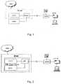
- a system model of an ADSL or a VDSLis shown in Fig.
- a filter in the ADSL or VDSL services communication systemcan be referred to as a Splitter.
- a DSL Access Multiplexer(DSLAM) is included.
- the DSLAMcan provide multi-path ADSL services or VDSL services.
- the amount of xDSL linesis closer to the amount of POTS lines, and may be nearly the same as that of the POTS lines eventually.
- the complexity, difficulty and maintenance cost of networking of the xDSLwill be greatly increased if the networking mode is the same to that shown in Fig. 1 .
- a new networking modethat is an Integrated Voice Data (IVD) networking mode, has been employed by operators.
- IVDIntegrated Voice Data
- the IVD networking modeis shown in Fig. 2 .
- the IVD networking systemmainly includes an IVD line card set in a Multiple Services Access Node (MSAN).
- the IVD line cardincludes an xTU-C (xDSL CO unit), a POTS (traditional telephone service) process unit, and a Low Pass Filter (LPF).
- the IVD line cardsupports POTS transmission process of xDSL service.
- xTU-CxDSL CO unit
- POTStraditional telephone service
- LPFLow Pass Filter
- the IVD line cardsupports POTS transmission process of xDSL service.
- the IVD networking modemay become a primary mode in the next generation network.
- a series of difficulties and problemswill be brought by the use of the IVD networking.
- the power consumption of deviceis relatively high. At the early stage, when the utilization ratio of xDSL line is rather low, the problem of high power consumption is much more noticeable.
- the DSLAMemploys a centralized multiplexing mode.
- the density of the utility of the DSLAM devicecan be increased gradually according to the increase of number of subscribers.
- the average utilization ratio of the DSLAM deviceis relatively high, and the power consumption is relatively low.
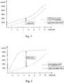
- a schematic diagram illustrating a relationship between the networking scale and the port utilization ratio in the DSLAM networking modeis as shown in Fig. 3 .
- Fig. 2in an IVD networking mode of Multiply Service Access Node (MSAN), all wideband ports should be deployed along with narrowband ports at one time.
- MSANMultiply Service Access Node
- Fig. 4shows the networking scale and the port utilization ratio of the IVD networking mode.
- the static power consumptionis rather high at the early stage of networking using the IVD mode.
- the static power consumption of 32ch POTSis around 3W
- the static power consumption of 32ch ADSLis near 10W when the ADSL is inactive.
- the IVDis only used as a POTS, the power consumption of the IVD is 4 times of that of a PSTN device. The higher power consumption is obviously contrary to the operator's objective of saving network's power.
- a method for saving power of xDSL lines in existing artincludes the application of L2/L3 low power consumption mode, Power management (port power management), Power cutback, and so on.
- WO 99/07162 Adiscloses a method for power conservation for POTS and modulated data transmission.
- an ADSL unitmay enter into low-power mode by shutting off the unnecessary sections of signal processing, transmitting and receiving circuitry; circuitry 115 to detect a resume signal must remain capable of signal detection during low power operation.
- the resume signalis detected, the ADSL unit resumes full power operation.
- ADSL link statesare defined to allow an ATU to enter a low power state without totally disconnecting the link.
- the ADSL link statesinclude L0, L1 and L3 which are respectively indicates full on, low power and Idle. Link state transitions can be performed.
- Embodiments of the present inventionprovide a xDSL access device and a method for saving power of communication device, so as to effectively reducing the power consumption when the xDSL line is inactive.
- An embodiment of the present inventionprovides a xDSL access device.
- the xDSL access deviceincludes a plurality of service units and a power control circuit, in which the power control circuit is adapted to cut off power supply of at least one service unit that is inactive of the plurality of service units according to the control signal to save power consumption of the xDSL access device.
- the power control circuitincludes a control signal unit which is adapted to transmit the control signal and a power control unit which is adapted to cut off power supply of at least one service unit of the plurality of service units according to the control signal transmitted from the control signal unit.
- the control signal unitinclude an external control signal unit adapted to receive a control signal from outside of the xDSL access device, and transmit the control signal to the power control unit; and/or an internal control signal unit adapted to generate a control signal derived from at least one of a master control module, an internal circuit module with independent power supply, an internal independent management module and a mechanical switch, and transmitting the control signal to the power control unit.
- the power control unitmay include a first power control unit for the whole xDSL access device, set at an input point of power supply of the xDSL access device, adapted to cut off power supply of the at least one service unit of the plurality of service units in the xDSL access device according to the control signal transmitted from the control signal unit; and/or a second power control unit for a service unit of the plurality of the service units, set at an input point of the power supply of the service unit inside the xDSL access device, and adapted to cut off power supply of the service unit according to the control signal come from the control signal unit.
- the plurality of service unitsincludes at least one line card in the xDSL access device or independent circuit modules in the line card.
- the power control circuit unitis set at an input point of the power supply of a wideband circuit module in the line card, and/or, at an input point of the power supply of a narrowband circuit module in the line card.
- the wideband circuit moduleincludes an Asymmetric Digital Subscriber Line (ADSL), ADSL2, ADSL2+, Very high rate ratio DSL (VDSL), VDSL2, or Single Line High Data Rate DSL (G.SHDSL) service modules, and the narrowband circuit module includes a plain old telephone service (POTS) or an Integrated Service Digital Network (ISDN) circuit module.
- ADSLAsymmetric Digital Subscriber Line
- ADSL2ADSL2, ADSL2+, Very high rate ratio DSL (VDSL), VDSL2, or Single Line High Data Rate DSL (G.SHDSL) service modules
- POTSplain old telephone service
- ISDNIntegrated Service Digital Network
- An embodiment of the present inventionprovides a method for saving power consumption of an xDSL access device.
- the methodincludes: receiving a control signal; and cutting off power supply of at least one service unit that is inactive in the xDSL access device according to the control signal to save power consumption of the xDSL access device.
- the service unitis an IVD line card in the xDSL access device or an independent circuit module in the IVD line card.
- the control signalis derived from outside of the IVD line card.
- the control signal derived from outside of the IVD line cardis generated by control of computer command lines and NMS graphical interface management software.
- the control signalis derived from a wideband circuit module in the IVD line card; and the cutting off power supply of at least one service unit that is inactive in the xDSL access device according to the control signal includes: cutting off power supply of a narrowband circuit module in the IVD line card according to the control signal from the wideband circuit module.
- the control signalis from a narrowband circuit module in the IVD line card; and the cutting off power supply of at least one service unit that is inactive in the xDSL access device according to the control signal includes: cutting off power supply of a wideband circuit module in the IVD line card according to the control signal from the narrowband circuit module.
- the control signalis derived from a mechanical switch or a jump line in the IVD line card.
- power supply of partial communication circuit modules, line cards, or the devicecan be cut off to save the power of the communication circuit modules, line cards, or the device, since the power control circuit, according to the embodiments of the present invention, is set at the input point of the power supply of the communication device, or at the input point of the power supply of service units inside the communication device.
- the power supply of whole or partial narrowband circuit modules and wideband circuit modulescan be cut off to reduce the power consumption of the wideband ports of the IVD line card, and to make the power consumption of the IVD device close to or even equal to the power level of the PSTN device if the active ratio of wideband ports is relatively low, because the power control circuits, according to the embodiments of the present invention, are set at the input points of the power supply of the narrowband circuit module and wideband circuit module.
- An application embodiment in an IVD line card of the present inventionincludes a power control circuit.
- the power control circuitis set at the input point of the power supply of the IVD line card or independent modules in the IVD line card; power supply of a wideband circuit module or a narrowband circuit module of the IVD line card can be cut off under the control of the power control unit if necessary. Therefore, the power of the IVD line card is saved.
- the scheme according to an embodiment of the present inventioncan be applied to the IVD line card or other similar communication devices, to reduce the power consumption.
- Fig. 5is a schematic diagram illustrating the structure of a communication device according to an embodiment of the present invention.
- the communication devicemainly includes a control signal unit and a power control unit.
- the control signal unitis used to transmit a control signal to the power control unit.
- the control signalis used to notify the power control unit to cut off power supply of some service units in the communication device, so as to cut off the power supply of the some service units, thereby saving the power consumption of the communication device.
- the control signal unitincludes an external control signal unit and/or an internal control signal unit, and the external control signal unit is used to receive a control signal from the outside of the communication device, and transmit the received control signal to the power control unit.
- the internal control signal unitis used to generate a control signal using at least one part of the communication device including a main control module, an internal circuit module with independent power supply, an internal independent management module or a mechanical switch.
- the control signalis transmitted to the power control unit, that is, the source of the control signal transmitted to the power control unit comes from the main control module, the internal circuit module with independent power supply, the internal independent management module, and/or the mechanical switch.
- the power control unitis used to cut off power supply of some service units in the communication device according to the control signal come from the control signal unit.
- the power control unitincludes a first power control unit for the whole communication device and/or a second power control unit for the service units.
- the first power control unit for the whole communication deviceis set at the input point of the power supply of the communication device.
- the first power control unitis used to cut off power supply of some of the service units in the communication device according to the control signal come from the control signal unit.
- the second power control unit for the service unitsis set at input point of the power supply of the service units of the communication device.
- the second power control unitis used to cut off power supply of the service units according to the control signal come from the control signal unit.
- the service unitscan be line cards in the communication device, or independent modules inside the line cards.
- the power control circuitis set at the input point of the power supply of the wideband circuit module and/or the narrowband circuit module of the line card.
- the specific implementationincludes the following solutions.
- the power control circuitis set at the input point of the power supply of the wideband circuit module, the control signal can come from the narrowband circuit module or other circuit modules with independent power supply inside the line card (including circuit modules with independent power supply inside the wideband circuit module).
- the whole or partial power supply of the wideband circuit modulecan be cut off according to the control signal from the narrowband circuit module or other circuit modules with independent power supply inside the line card (including the circuit module with independent power supply inside the wideband circuit module). The power consumption is saved.
- the control signalcan come from the wideband circuit module or other circuit modules with independent power supply inside the line card (including circuit modules with independent power supply inside the narrowband circuit module).
- the power supply of the whole or partial narrowband circuit modulemay be cut off according to the control signal from the wideband circuit module or other circuit modules with independent power supply inside the line card (including circuit modules with independent power supply inside the narrowband circuit module). The power consumption is saved.
- the wideband circuit module inside the IVD line card mentioned-aboverefers to such service module as ADSL/ADSL2/ADSL2+/VDSL/VDSL2/G.SHDSL
- the narrowband circuit module inside the IVD line card mentioned-aboverefers to such circuit module as POTS/ISDN.
- the method according to an embodiment of the present inventionis shown in Fig. 6 .
- Block 6-1Set a power control circuit at the input point of the power supply of the IVD line card.
- the power control circuitincludes the control signal unit and the power control unit, as described above.
- power control circuitsneed to be set at the input point of the power supply of the wideband circuit module and at the input point of the power supply of the narrowband circuit module respectively; and the power control circuit set at the input point of the power supply of the wideband circuit module cut off power supply of the wideband circuit module, while the power control circuit set at the input point of the power supply of the narrowband circuit module cut off power supply of the narrowband circuit module.
- Block 6-2Configure control signals with different source for the power control circuit.
- the power control circuitis set at the input point of the power supply of the IVD line card, in the present embodiment, there are three implementations for setting the source of the control signals for the power control circuit.
- control signalsare from the outside of the line card, such as the system control module or other monitor modules.
- the system control module or other monitor modulestransmits the control signals to the power control circuit through a backboard.
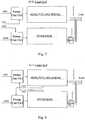
- the power supply control function of an IVD line card when power control signals come from outside of the IVD line cardis illustrated in Fig. 7 .
- a control signal con1is derived from a first power control circuit Power Con Cir1
- a control signal con2is derived from a second power control circuit Power Con Cir2.
- the control signals from the backboardare used to cut off the whole or partial power supply of the wideband circuit module or the narrowband circuit module, so the power consumption is saved.
- the control signal from the backboardis selectively derived from the system master control board, the system monitor board, other public management modules, other public monitor and control modules, or the like.
- the system master control board, the system monitor board, other public management modules, other public monitor and control modules, or the likeare controlled by a host computer command lines, or a management software systems such as Network Management System (NMS) graphical interfaces and the like.
- NMSNetwork Management System
- power supply for service units such as the wideband circuit module and so oncan be controlled by the host computer command lines or the management software systems. In other words, whether the power of service units such as the wideband circuit module and the like is supplied by the power control circuit of input point of the power supply of service units such as the wideband circuit module and the like is controlled.
- the control signalsare derived from a different circuit module inside the line card, that is, the control signal for power supply of the wideband circuit module comes from the narrowband circuit module, while the control signal for power supply of the narrowband circuit module comes from the wideband circuit module.
- the power supply control function of the IVD line cardis as shown in Fig. 8 .
- the control signals for power supply of the wideband circuit module and the narrowband circuit moduleall come from a same independent management module inside the line card.
- the power supply control function of the IVD line cardis as shown in Fig. 9 .
- the independent management module in Fig. 9is a Power Con Model (power control module) configured with a Management Port.
- control signalsare derived from a mechanical switch or a jump line.
- the power supply control function of the IVD line cardis shown in Fig. 10 .
- the control signalcome from the first power control circuit Power Con Cir1 is con1
- the control signalcome from the second power control circuit Power Con Cir2 is con2
- the control signalsare derived from an on-off Switch.
- At least one of the three above-mentioned sources of control signalsmay be chosen as the source of control signals introduced by the power control circuit.
- Block 6-3Configure working modes for the IVD line card using the power control circuit and the control signals to be introduced.
- the power input of the wideband circuit moduleis -48VI, that is converted to power needed by the wideband circuit module through Direct Current/Direct Current (DC/DC) conversion.
- the first power control circuit Power Con Cir1is the power control circuit of the wideband circuit module. Control signals generated with one of the three above-mentioned manners may cut off the power supply of the wideband circuit module using the Power Con Cir1. Therefore, the power consumption of the wideband circuit is reduced.
- the power input of narrowband circuit moduleis -48VII, and the power input provides high-voltage power supply for the POTS feed-electricity circuit.
- the second power control circuit Power Con Cir2is the power control circuit of the narrowband circuit module. Control signals generated in one of the three above-mentioned manners may cut off the power supply of the narrowband circuit module using the Power Con Cir2. Therefore, the power consumption of the narrowband circuit is reduced.
- Power Con Cir1 and Power Con Cir2are independently with each other.
- the wideband circuit module or the narrowband circuit module of the IVD line cardcan be closed with application requirements, that is, the IVD line card is configured with different working modes using the configured power control circuit and control signals.
- Fig. 11is the schematic diagram illustrating the relationship between working modes of the IVD line card and the logical relationship of the power control circuits.
- the powermay be saved about 70% if the IVD line card is working in the POTS Only Mode, while the power may be saved about 30% if the IVD line card is working in the ADSL Only mode.
- Block 6-4The NMS uses the power control circuit to implement centralized management of different IVD line cards.
- the NMScan implement centralized management of the different IVD line cards through controlling the control signals transmitted to the power control circuit. That is, the NMS can configure ratios of working modes for IVD line cards according to the ratios occupied by the subscriber ports of the IVD line cards. Power consumption of the whole network can be reduced by the centralized management.
- Fig. 12is a schematic diagram illustrating the centralized management. As shown in Fig. 12 , power consumption of MSAN in different modes can be estimated, and more than 70% of the power consumption may be saved.
- the method according to the embodiments of the present inventionmay also be applied to other modules, line cards or devices.
Landscapes
- Engineering & Computer Science (AREA)
- Signal Processing (AREA)
- Computer Networks & Wireless Communication (AREA)
- Telephonic Communication Services (AREA)
- Interface Circuits In Exchanges (AREA)
- Devices For Supply Of Signal Current (AREA)
- Direct Current Feeding And Distribution (AREA)
- Mobile Radio Communication Systems (AREA)
Description
- The present invention relates to communication field, and more particularly, to a communication device and a method for saving static power consumption of the communication device.
- Digital Subscriber Line (xDSL, such as Asymmetric DSL, Very high data rate DSL, etc.) is used in point-to-point transmission technology, using copper twisted-pairs as transmission media. The DSL technology supports both symmetric and asymmetric transmission modes in subscriber loops of traditional POTS (a plain old telephone service), so that a transmission bottleneck of the "last kilometer" often happening between a network service provider and an end subscriber is solved. Because the xDSL provides high-bandwidth services by employing copper twisted-pairs, the investments of operators are effectively guaranteed to be returned, and the subscribers are provided with wideband services. Accordingly, the xDSL is well developed all over the world.
- Asymmetric Digital Subscriber Line (ADSL) is a type of the xDSL, which is appropriate for transmitting asymmetric data streams used in personal wideband access services, wherein the amount of data of downlink streams (from a Central Office, CO to a Customer Premise Equipment, CPE) of a personal wideband access services is extremely larger than that of uplink (from the CPE to the CO) streams. The ADSL has overpowering advantages in personal wideband access applications. Till now, more than 50,000,000 subscribers enjoy multimedia services provided by the ADSL, such as high-speed net-surfing, video services. ADSL service providers develop a new "gold mine" on the twisted-pair, making the ADSL services become another important income source besides the POTS.
- According to the growing bandwidth demands of the subscribers, an access technology providing higher bandwidth and more flexible allocation of uplink and downlink bandwidths, such as the Very high data rate DSL (VDSL), is applied. Another widely used DSL technology is Single Line High Data Rate Digital Subscriber Line (G.SHDSL). The G.SHDSL is more often used by business consumers because it can provide asymmetric services.
- All of the ADSL, ADSL2+ (second generation ADSL), and the VDSL employ frequencies higher than that used in traditional telephone signals (below 3.4KHz). The frequency range of the ADSL is 25.875KHz∼1104KHz, the frequency range of the ADSL2+ is 25.875KHz∼2208KHz, and the frequency range of the VDSL may be 25KHz∼30MHz. As transmitting on different frequency bands, the xDSL and the POTS services can transmit in one telephone line. The mixed signals of the xDSL and the POTS services can be separated by filters set in transceivers on both ends of the telephone line. A system model of an ADSL or a VDSL is shown in
Fig. 1 , a filter in the ADSL or VDSL services communication system can be referred to as a Splitter. In the system, a DSL Access Multiplexer (DSLAM) is included. The DSLAM can provide multi-path ADSL services or VDSL services. - According to the rapidly growing applications of xDSL, the amount of xDSL lines is closer to the amount of POTS lines, and may be nearly the same as that of the POTS lines eventually. The complexity, difficulty and maintenance cost of networking of the xDSL will be greatly increased if the networking mode is the same to that shown in
Fig. 1 . Thus, a new networking mode, that is an Integrated Voice Data (IVD) networking mode, has been employed by operators. - The IVD networking mode is shown in
Fig. 2 . The IVD networking system mainly includes an IVD line card set in a Multiple Services Access Node (MSAN). The IVD line card includes an xTU-C (xDSL CO unit), a POTS (traditional telephone service) process unit, and a Low Pass Filter (LPF). The IVD line card supports POTS transmission process of xDSL service. There are a series of advantages of the IVD networking mode, such as low stock cost, low networking complexity, low maintenance cost, and so on. Accordingly, the IVD networking mode may become a primary mode in the next generation network. However, a series of difficulties and problems will be brought by the use of the IVD networking. For example, the power consumption of device is relatively high. At the early stage, when the utilization ratio of xDSL line is rather low, the problem of high power consumption is much more noticeable. - As shown in
Fig. 1 , the DSLAM employs a centralized multiplexing mode. In this mode, the density of the utility of the DSLAM device can be increased gradually according to the increase of number of subscribers. The average utilization ratio of the DSLAM device is relatively high, and the power consumption is relatively low. A schematic diagram illustrating a relationship between the networking scale and the port utilization ratio in the DSLAM networking mode is as shown inFig. 3 . - As shown in
Fig. 2 , in an IVD networking mode of Multiply Service Access Node (MSAN), all wideband ports should be deployed along with narrowband ports at one time. At the early stage of networking, the ratio of wideband subscribers to narrowband subscribers is relatively low, and the power consumption of wideband part is relatively high.Fig. 4 shows the networking scale and the port utilization ratio of the IVD networking mode. The static power consumption is rather high at the early stage of networking using the IVD mode. For example, in a typical 32ch IVD, the static power consumption of 32ch POTS is around 3W, while the static power consumption of 32ch ADSL is near 10W when the ADSL is inactive. In an extreme case, the IVD is only used as a POTS, the power consumption of the IVD is 4 times of that of a PSTN device. The higher power consumption is obviously contrary to the operator's objective of saving network's power. - Implementations for reducing power consumption are provided currently. A method for saving power of xDSL lines in existing art includes the application of L2/L3 low power consumption mode, Power management (port power management), Power cutback, and so on.
WO 99/07162 A - According to ITU-T G.992.2 "splitterless asymmetric digital subscriber line (ADSL) transceivers", ADSL link states are defined to allow an ATU to enter a low power state without totally disconnecting the link. The ADSL link states include L0, L1 and L3 which are respectively indicates full on, low power and Idle. Link state transitions can be performed.
- The inventor found in the inventing process that the methods for saving power for xDSL lines in the existing art just concentrate on how to save power when the xDSL lines are active, and no feasible solution is given for saving the static power consumption when the xDSL lines are inactive.
- Embodiments of the present invention provide a xDSL access device and a method for saving power of communication device, so as to effectively reducing the power consumption when the xDSL line is inactive.
- An embodiment of the present invention provides a xDSL access device. The xDSL access device includes a plurality of service units and a power control circuit, in which the power control circuit is adapted to cut off power supply of at least one service unit that is inactive of the plurality of service units according to the control signal to save power consumption of the xDSL access device.
- The power control circuit includes a control signal unit which is adapted to transmit the control signal and a power control unit which is adapted to cut off power supply of at least one service unit of the plurality of service units according to the control signal transmitted from the control signal unit.
- The control signal unit include an external control signal unit adapted to receive a control signal from outside of the xDSL access device, and transmit the control signal to the power control unit; and/or an internal control signal unit adapted to generate a control signal derived from at least one of a master control module, an internal circuit module with independent power supply, an internal independent management module and a mechanical switch, and transmitting the control signal to the power control unit.
- The power control unit may include a first power control unit for the whole xDSL access device, set at an input point of power supply of the xDSL access device, adapted to cut off power supply of the at least one service unit of the plurality of service units in the xDSL access device according to the control signal transmitted from the control signal unit; and/or a second power control unit for a service unit of the plurality of the service units, set at an input point of the power supply of the service unit inside the xDSL access device, and adapted to cut off power supply of the service unit according to the control signal come from the control signal unit.
- The plurality of service units includes at least one line card in the xDSL access device or independent circuit modules in the line card.
- The power control circuit unit is set at an input point of the power supply of a wideband circuit module in the line card, and/or, at an input point of the power supply of a narrowband circuit module in the line card.
- The wideband circuit module includes an Asymmetric Digital Subscriber Line (ADSL), ADSL2, ADSL2+, Very high rate ratio DSL (VDSL), VDSL2, or Single Line High Data Rate DSL (G.SHDSL) service modules, and the narrowband circuit module includes a plain old telephone service (POTS) or an Integrated Service Digital Network (ISDN) circuit module.
- An embodiment of the present invention provides a method for saving power consumption of an xDSL access device. The method includes: receiving a control signal; and cutting off power supply of at least one service unit that is inactive in the xDSL access device according to the control signal to save power consumption of the xDSL access device.
- The service unit is an IVD line card in the xDSL access device or an independent circuit module in the IVD line card.
- The control signal is derived from outside of the IVD line card.
- The control signal derived from outside of the IVD line card is generated by control of computer command lines and NMS graphical interface management software.
- The control signal is derived from a wideband circuit module in the IVD line card; and the cutting off power supply of at least one service unit that is inactive in the xDSL access device according to the control signal includes: cutting off power supply of a narrowband circuit module in the IVD line card according to the control signal from the wideband circuit module.
- The control signal is from a narrowband circuit module in the IVD line card; and the cutting off power supply of at least one service unit that is inactive in the xDSL access device according to the control signal includes: cutting off power supply of a wideband circuit module in the IVD line card according to the control signal from the narrowband circuit module.
- The control signal is derived from a mechanical switch or a jump line in the IVD line card.
- It can be seen from the technical solution provided by the present invention that, power supply of partial communication circuit modules, line cards, or the device can be cut off to save the power of the communication circuit modules, line cards, or the device, since the power control circuit, according to the embodiments of the present invention, is set at the input point of the power supply of the communication device, or at the input point of the power supply of service units inside the communication device. Further, the power supply of whole or partial narrowband circuit modules and wideband circuit modules can be cut off to reduce the power consumption of the wideband ports of the IVD line card, and to make the power consumption of the IVD device close to or even equal to the power level of the PSTN device if the active ratio of wideband ports is relatively low, because the power control circuits, according to the embodiments of the present invention, are set at the input points of the power supply of the narrowband circuit module and wideband circuit module.
Fig. 1 is a schematic diagram illustrating a system model of ADSL and VDSL.Fig. 2 is a schematic diagram illustrating an IVD networking mode.Fig. 3 is a schematic diagram illustrating networking scale and port utilization ratio in the DSLAM networking mode.Fig. 4 is a schematic diagram illustrating networking scale and port utilization ratio in the IVD networking mode.Fig. 5 is a schematic diagram illustrating the structure of a communication device according to an embodiment of the present invention.Fig. 6 is a flow chart of a method according to an embodiment of the present invention.Fig. 7 is a schematic diagram illustrating the power supply control function of an IVD line card when power control signals come from outside the IVD line card.Fig. 8 is a schematic diagram illustrating the power supply control function of an IVD line card when power control signals for a wideband circuit module come from a narrowband circuit module, and power control signals for the narrowband circuit module come from the control power supply of the communication device or service units of the communication device, i.e. power supply of some service units (including independent circuit modules of the service units) is controlled to be cut off to save the power consumption.- An application embodiment in an IVD line card of the present invention includes a power control circuit. The power control circuit is set at the input point of the power supply of the IVD line card or independent modules in the IVD line card; power supply of a wideband circuit module or a narrowband circuit module of the IVD line card can be cut off under the control of the power control unit if necessary. Therefore, the power of the IVD line card is saved. The scheme according to an embodiment of the present invention can be applied to the IVD line card or other similar communication devices, to reduce the power consumption.
- Specific description will be given with reference to the embodiments and the accompany drawings.
Fig. 5 is a schematic diagram illustrating the structure of a communication device according to an embodiment of the present invention. The communication device mainly includes a control signal unit and a power control unit. - The control signal unit is used to transmit a control signal to the power control unit. The control signal is used to notify the power control unit to cut off power supply of some service units in the communication device, so as to cut off the power supply of the some service units, thereby saving the power consumption of the communication device.
- The control signal unit includes an external control signal unit and/or an internal control signal unit, and the external control signal unit is used to receive a control signal from the outside of the communication device, and transmit the received control signal to the power control unit.
- The internal control signal unit is used to generate a control signal using at least one part of the communication device including a main control module, an internal circuit module with independent power supply, an internal independent management module or a mechanical switch. The control signal is transmitted to the power control unit, that is, the source of the control signal transmitted to the power control unit comes from the main control module, the internal circuit module with independent power supply, the internal independent management module, and/or the mechanical switch.
- The power control unit is used to cut off power supply of some service units in the communication device according to the control signal come from the control signal unit.
- The power control unit includes a first power control unit for the whole communication device and/or a second power control unit for the service units.
- The first power control unit for the whole communication device is set at the input point of the power supply of the communication device. The first power control unit is used to cut off power supply of some of the service units in the communication device according to the control signal come from the control signal unit.
- The second power control unit for the service units is set at input point of the power supply of the service units of the communication device. The second power control unit is used to cut off power supply of the service units according to the control signal come from the control signal unit. The service units can be line cards in the communication device, or independent modules inside the line cards.
- As an embodiment, in an IVD line card, the power control circuit is set at the input point of the power supply of the wideband circuit module and/or the narrowband circuit module of the line card. The specific implementation includes the following solutions.
- (1) setting the power control circuit at the input point of the power supply of the wideband circuit module.
- (2) setting the power control circuit at the input point of the power supply of the narrowband circuit module.
- (3) setting the power control circuit at the input point of the power supply of the wideband circuit module and the narrowband circuit module simultaneously.
- If the solutions (1) and (3) were used, the power control circuit is set at the input point of the power supply of the wideband circuit module, the control signal can come from the narrowband circuit module or other circuit modules with independent power supply inside the line card (including circuit modules with independent power supply inside the wideband circuit module). The whole or partial power supply of the wideband circuit module can be cut off according to the control signal from the narrowband circuit module or other circuit modules with independent power supply inside the line card (including the circuit module with independent power supply inside the wideband circuit module). The power consumption is saved.
- If the solution (2) and (3) were used, the power control circuit is set at the input point of the power supply of the narrowband circuit module, the control signal can come from the wideband circuit module or other circuit modules with independent power supply inside the line card (including circuit modules with independent power supply inside the narrowband circuit module). The power supply of the whole or partial narrowband circuit module may be cut off according to the control signal from the wideband circuit module or other circuit modules with independent power supply inside the line card (including circuit modules with independent power supply inside the narrowband circuit module). The power consumption is saved.
- The wideband circuit module inside the IVD line card mentioned-above refers to such service module as ADSL/ADSL2/ADSL2+/VDSL/VDSL2/G.SHDSL, and the narrowband circuit module inside the IVD line card mentioned-above refers to such circuit module as POTS/ISDN.
- Taking the IVD line card as an example, the method according to an embodiment of the present invention is shown in
Fig. 6 . - Block 6-1: Set a power control circuit at the input point of the power supply of the IVD line card.
- The power control circuit includes the control signal unit and the power control unit, as described above.
- According to the embodiment, power control circuits need to be set at the input point of the power supply of the wideband circuit module and at the input point of the power supply of the narrowband circuit module respectively; and the power control circuit set at the input point of the power supply of the wideband circuit module cut off power supply of the wideband circuit module, while the power control circuit set at the input point of the power supply of the narrowband circuit module cut off power supply of the narrowband circuit module.
- Block 6-2: Configure control signals with different source for the power control circuit.
- After the power control circuit is set at the input point of the power supply of the IVD line card, in the present embodiment, there are three implementations for setting the source of the control signals for the power control circuit.
- In the first implementation, the control signals are from the outside of the line card, such as the system control module or other monitor modules. The system control module or other monitor modules transmits the control signals to the power control circuit through a backboard. The power supply control function of an IVD line card when power control signals come from outside of the IVD line card is illustrated in
Fig. 7 . A control signal con1 is derived from a first power control circuit Power Con Cir1, and a control signal con2 is derived from a second power control circuit Power Con Cir2. For example, the control signals from the backboard are used to cut off the whole or partial power supply of the wideband circuit module or the narrowband circuit module, so the power consumption is saved. The control signal from the backboard is selectively derived from the system master control board, the system monitor board, other public management modules, other public monitor and control modules, or the like. The system master control board, the system monitor board, other public management modules, other public monitor and control modules, or the like are controlled by a host computer command lines, or a management software systems such as Network Management System (NMS) graphical interfaces and the like. i.e. power supply for service units such as the wideband circuit module and so on can be controlled by the host computer command lines or the management software systems. In other words, whether the power of service units such as the wideband circuit module and the like is supplied by the power control circuit of input point of the power supply of service units such as the wideband circuit module and the like is controlled. - In a second implementation, the control signals are derived from a different circuit module inside the line card, that is, the control signal for power supply of the wideband circuit module comes from the narrowband circuit module, while the control signal for power supply of the narrowband circuit module comes from the wideband circuit module. In this case, the power supply control function of the IVD line card is as shown in
Fig. 8 . Optionally, the control signals for power supply of the wideband circuit module and the narrowband circuit module all come from a same independent management module inside the line card. In this case, the power supply control function of the IVD line card is as shown inFig. 9 . InFig. 8 andFig. 9 , the control signal come from the first power control circuit Power Con Cir1 is con1, the control signal come from the second power control circuit Power Con Cir2 is con2. The independent management module inFig. 9 is a Power Con Model (power control module) configured with a Management Port. - In a third implementation, the control signals are derived from a mechanical switch or a jump line. In this case, the power supply control function of the IVD line card is shown in
Fig. 10 . Similarly, inFig. 10 , the control signal come from the first power control circuit Power Con Cir1 is con1, the control signal come from the second power control circuit Power Con Cir2 is con2, and the control signals are derived from an on-off Switch. - According to the embodiment of the present invention, at least one of the three above-mentioned sources of control signals may be chosen as the source of control signals introduced by the power control circuit.
- Block 6-3: Configure working modes for the IVD line card using the power control circuit and the control signals to be introduced.
- As shown in
Fig. 7 to Fig. 10 , the power input of the wideband circuit module is -48VI, that is converted to power needed by the wideband circuit module through Direct Current/Direct Current (DC/DC) conversion. The first power control circuit Power Con Cir1 is the power control circuit of the wideband circuit module. Control signals generated with one of the three above-mentioned manners may cut off the power supply of the wideband circuit module using the Power Con Cir1. Therefore, the power consumption of the wideband circuit is reduced. - The power input of narrowband circuit module is -48VII, and the power input provides high-voltage power supply for the POTS feed-electricity circuit. The second power control circuit Power Con Cir2 is the power control circuit of the narrowband circuit module. Control signals generated in one of the three above-mentioned manners may cut off the power supply of the narrowband circuit module using the Power Con Cir2. Therefore, the power consumption of the narrowband circuit is reduced.
- Power Con Cir1 and Power Con Cir2 are independently with each other.
- In the IVD line card shown in
Fig. 7 to Fig. 10 , the wideband circuit module or the narrowband circuit module of the IVD line card can be closed with application requirements, that is, the IVD line card is configured with different working modes using the configured power control circuit and control signals.Fig. 11 is the schematic diagram illustrating the relationship between working modes of the IVD line card and the logical relationship of the power control circuits. - As shown in
Fig. 11 , the power may be saved about 70% if the IVD line card is working in the POTS Only Mode, while the power may be saved about 30% if the IVD line card is working in the ADSL Only mode. - Block 6-4: The NMS uses the power control circuit to implement centralized management of different IVD line cards.
- In this embodiment, the NMS can implement centralized management of the different IVD line cards through controlling the control signals transmitted to the power control circuit. That is, the NMS can configure ratios of working modes for IVD line cards according to the ratios occupied by the subscriber ports of the IVD line cards. Power consumption of the whole network can be reduced by the centralized management.
Fig. 12 is a schematic diagram illustrating the centralized management. As shown inFig. 12 , power consumption of MSAN in different modes can be estimated, and more than 70% of the power consumption may be saved. - The method according to the embodiments of the present invention may also be applied to other modules, line cards or devices.
- The foregoing is only preferred embodiments of the present invention. The protection scope of the present invention, however, is not limited to the above description. Any change or substitution, within the technical scope disclosed by the present invention, easily occurring to those skilled in the art should be covered by the protection scope of the present invention. Therefore, the protection scope of the present invention should be according to the claims.
Claims (5)
- An Integrated Voice Data, IVD, line card,characterized by comprising:a wideband circuit module, a narrowband circuit module and a power control circuit, whereinthe power control circuit is adapted to cut off power supply of the wideband circuit module when the IVD line card works in a Plain Old Telephone Service, POTS, only mode, and to cut off power supply of the narrowband circuit module when the IVD line card works in an Asymmetric Digital Subscriber Line, ADSL, only mode;wherein the power control circuit comprises:a control signal unit, adapted to transmit a control signal; anda power control unit, adapted to cut off the power supply of the wideband circuit module or the narrowband circuit module according to the control signal transmitted from the control signal unit;wherein the control signal unit comprises:an external control signal unit, adapted to receive the control signal from outside of the IVD line card, and transmit the control signal to the power control unit, wherein the control signal is generated by computer command lines or Network Management System, NMS, graphical interface management software.
- The IVD line card of claim 1, wherein the power control circuit is set at an input point of the power supply of the wideband circuit module in the IVD line card, and/or, at an input point of the power supply of the narrowband circuit module in the IVD line card.
- The IVD line card of claim 2, wherein the wideband circuit module comprises an Asymmetric Digital Subscriber Line (ADSL), ADSL2, ADSL2+, Very high rate ratio DSL (VDSL), VDSL2, or Single Line High Data Rate DSL (G.SHDSL) service modules, and the narrowband circuit module comprises a plain old telephone service (POTS) or an Integrated Service Digital Network (ISDN) circuit module.
- A Multiply Service Access Node, MSAN, comprising an Integrated Voice Data, IVD, line card as described in any one of claims 1 to 3.
- A method for saving power consumption of an Integrated Voice Data, IVD, line card,characterized by comprising:receiving a control signal from outside of the IVD line card, wherein the control signal is generated by computer command lines or Network Management System, NMS, graphical interface management software, and the control signal is used to cut off power supply of a wideband circuit module of the IVD line card when the IVD line card works in a Plain Old Telephone Service, POTS, only mode, and to cut off power supply of a narrowband circuit module of the IVD line card when the IVD line card works in an Asymmetric Digital Subscriber Line, ADSL, only mode;cutting off power supply of the wideband circuit module or the narrowband circuit module according to the control signal.
Applications Claiming Priority (2)
| Application Number | Priority Date | Filing Date | Title |
|---|---|---|---|
| CNB2005100909392ACN100502291C (en) | 2005-08-22 | 2005-08-22 | A communication device and method for saving static power consumption of the communication device |
| PCT/CN2006/002086WO2007022699A1 (en) | 2005-08-22 | 2006-08-17 | A communication apparatus and a method for saving static power consumption of the communication apparatus |
Publications (3)
| Publication Number | Publication Date |
|---|---|
| EP1843610A1 EP1843610A1 (en) | 2007-10-10 |
| EP1843610A4 EP1843610A4 (en) | 2008-03-05 |
| EP1843610B1true EP1843610B1 (en) | 2016-03-30 |
Family
ID=37425731
Family Applications (1)
| Application Number | Title | Priority Date | Filing Date |
|---|---|---|---|
| EP06775404.4ANot-in-forceEP1843610B1 (en) | 2005-08-22 | 2006-08-17 | A communication apparatus and a method for saving static power consumption of the communication apparatus |
Country Status (6)
| Country | Link |
|---|---|
| US (1) | US7849338B2 (en) |
| EP (1) | EP1843610B1 (en) |
| CN (2) | CN100502291C (en) |
| BR (1) | BRPI0614940B1 (en) |
| MY (1) | MY156421A (en) |
| WO (1) | WO2007022699A1 (en) |
Families Citing this family (15)
| Publication number | Priority date | Publication date | Assignee | Title |
|---|---|---|---|---|
| WO2008088912A1 (en) | 2007-01-16 | 2008-07-24 | Ikanos Communications, Inc. | Method and apparatus for dsl line card power management |
| CN101232659B (en)* | 2008-02-20 | 2011-04-20 | 中兴通讯股份有限公司 | Method for reducing single board power consumption |
| EP2139155A1 (en)* | 2008-06-27 | 2009-12-30 | Nokia Siemens Networks Oy | Method and device for processing data and communication system comprising such device |
| CN101370207B (en)* | 2008-09-11 | 2012-07-04 | 华为终端有限公司 | Method, apparatus and system for reducing termination power loss |
| CN101833365B (en)* | 2009-03-09 | 2011-09-14 | 华为技术有限公司 | Single board energy saving device, method and single board |
| CN102300290A (en)* | 2010-06-22 | 2011-12-28 | 中兴通讯股份有限公司 | Consumption-reducing device and method for baseband processing unit (BBU) of base station |
| CN101938378B (en)* | 2010-09-13 | 2015-01-28 | 中兴通讯股份有限公司 | Veneer charging and discharging management system and application method thereof |
| US9189005B2 (en)* | 2010-11-26 | 2015-11-17 | Nec Corporation | Transmission power control circuit and transmission device, transmission power control method, program |
| CN102204364B (en) | 2011-04-26 | 2013-01-16 | 华为终端有限公司 | Method and server for processing service |
| US9392106B2 (en)* | 2011-08-09 | 2016-07-12 | Alcatel Lucent | System and method for reducing power consumption in telecommunication systems |
| CN102968168A (en)* | 2012-10-24 | 2013-03-13 | 福建星网锐捷网络有限公司 | Method for enabling wire clip, management board and wire clip |
| TWI500292B (en)* | 2012-11-08 | 2015-09-11 | Realtek Semiconductor Corp | Energy efficient network communication device and method |
| CN105245350B (en)* | 2015-08-31 | 2019-01-15 | 广州市优普计算机有限公司 | A kind of DSL power-on and power-off means of communication and its equipment |
| CN109672631A (en)* | 2017-10-16 | 2019-04-23 | 北京中科晶上科技股份有限公司 | High speed power board and control method based on VPX standard |
| CN110034938B (en)* | 2019-03-28 | 2021-01-26 | 烽火通信科技股份有限公司 | Method and system for reducing board card power consumption |
Family Cites Families (18)
| Publication number | Priority date | Publication date | Assignee | Title |
|---|---|---|---|---|
| US4484028A (en)* | 1982-11-01 | 1984-11-20 | Motorola, Inc. | Digital loop transceiver having a power up/down circuit |
| JPH05327587A (en)* | 1992-04-01 | 1993-12-10 | Nec Corp | Radio communication equipment |
| US5754870A (en)* | 1996-02-16 | 1998-05-19 | New Media Corp. | Power management of a computer plug-in card having a remote data link |
| US6208670B1 (en)* | 1997-03-10 | 2001-03-27 | Conklin Corporation | Digital carrier system for rural telephone and data applications |
| US6757268B1 (en)* | 1997-07-21 | 2004-06-29 | Winstar Corporation | Metropolitan wide area network |
| US5956323A (en)* | 1997-07-30 | 1999-09-21 | Nokia High Speed Access Products Inc. | Power conservation for pots and modulated data transmission |
| US6480487B1 (en)* | 1998-08-24 | 2002-11-12 | Verizon Services Group | Digital loop carrier remote terminal having integrated digital subscriber plug-in line cards for multiplexing of telephone and broadband signals |
| US6597689B1 (en)* | 1998-12-30 | 2003-07-22 | Nortel Networks Limited | SVC signaling system and method |
| JP3928292B2 (en)* | 1999-03-01 | 2007-06-13 | ソニー株式会社 | Electronics |
| US7075903B1 (en)* | 1999-04-14 | 2006-07-11 | Adc Telecommunications, Inc. | Reduced power consumption in a communication device |
| KR100400168B1 (en)* | 1999-07-21 | 2003-10-01 | 삼성전자주식회사 | Method for saving battery using power control of display unit in a potable phone |
| US6799279B1 (en)* | 2000-06-21 | 2004-09-28 | Matsushita Electric Industrial Co., Ltd. | Method and apparatus for stopping supply of power to a specific function for playing contents stored on media in response to a low battery level |
| US6898280B1 (en)* | 2000-11-15 | 2005-05-24 | Lucent Technologies Inc. | Line card and method for supporting pots, asymmetric DSL and symmetric DSL services |
| US6952785B1 (en)* | 2002-03-04 | 2005-10-04 | Cisco Technology, Inc. | Methods and apparatus for powering a data communications port |
| JP4127016B2 (en)* | 2002-10-30 | 2008-07-30 | 日本電気株式会社 | Mobile phone |
| US20050152300A1 (en)* | 2003-12-18 | 2005-07-14 | Idirect Incorporated | Virtual router system, method and apparatus |
| CN1555206A (en)* | 2003-12-23 | 2004-12-15 | 冯柯霖 | Power saving device for mobile phone |
| US7613938B2 (en)* | 2006-03-08 | 2009-11-03 | Alcatel Lucent | Power cycle circuit |
- 2005
- 2005-08-22CNCNB2005100909392Apatent/CN100502291C/ennot_activeExpired - Fee Related
- 2006
- 2006-08-17MYMYPI20080251Apatent/MY156421A/enunknown
- 2006-08-17CNCN2006800122534Apatent/CN101161002B/ennot_activeExpired - Fee Related
- 2006-08-17WOPCT/CN2006/002086patent/WO2007022699A1/enactiveApplication Filing
- 2006-08-17EPEP06775404.4Apatent/EP1843610B1/ennot_activeNot-in-force
- 2006-08-17BRBRPI0614940-5Apatent/BRPI0614940B1/ennot_activeIP Right Cessation
- 2007
- 2007-08-07USUS11/834,758patent/US7849338B2/enactiveActive
Also Published As
| Publication number | Publication date |
|---|---|
| WO2007022699A1 (en) | 2007-03-01 |
| MY156421A (en) | 2016-02-26 |
| CN1866839A (en) | 2006-11-22 |
| CN100502291C (en) | 2009-06-17 |
| BRPI0614940A2 (en) | 2013-01-01 |
| US7849338B2 (en) | 2010-12-07 |
| BRPI0614940B1 (en) | 2018-02-14 |
| CN101161002A (en) | 2008-04-09 |
| EP1843610A4 (en) | 2008-03-05 |
| EP1843610A1 (en) | 2007-10-10 |
| CN101161002B (en) | 2011-04-06 |
| US20080059821A1 (en) | 2008-03-06 |
Similar Documents
| Publication | Publication Date | Title |
|---|---|---|
| EP1843610B1 (en) | A communication apparatus and a method for saving static power consumption of the communication apparatus | |
| EP1284087B1 (en) | INTEGRATED TELEPHONE SET WITH AN xDSL-MODEM | |
| US9014244B2 (en) | Methods of implementing low-power mode for DSL modems | |
| US7142590B2 (en) | Method and system for oversubscribing a DSL modem | |
| JP2003504971A (en) | Method and apparatus for combining voice and XDSL line card functions | |
| CN1276948A (en) | Power conservation for POTS and modulated data transmission | |
| KR20010023363A (en) | Apparatus and method for concurrent voice and data transmission | |
| US20110019725A1 (en) | Dsl method having variable upload/download bit rate and application-specific dynamic profile switching | |
| CN101136659A (en) | A method, system and device for eliminating xDSL multi-pair crosstalk | |
| CN103828250B (en) | For saving the method for the power in telecommunication system | |
| CN100367721C (en) | Method and system for DSL power saving | |
| US6647024B1 (en) | System and method for an all digital communication system with a life line | |
| EP2071752A1 (en) | A method,system of dada transmission | |
| US7142591B2 (en) | Method and system for oversubscribing a pool of modems | |
| CN101159509B (en) | Method, system and device for power management | |
| US20080130247A1 (en) | Broadband-narrowband combining board in integrated access apparatus | |
| US20050231882A1 (en) | Device for controlling an xdsl communication line | |
| EP1626548B1 (en) | Processing apparatus of broadband and narrowband services in a communication device and method thereof | |
| CN101741606A (en) | A VDSL2 configuration management model based on actual business application scenarios | |
| CN101317429A (en) | Apparatus, system and method for diagnosing digital subscriber line transceiver interoperability problems | |
| CA2464132C (en) | Method and system for dsl power saving | |
| Pickering | Wireline access evolution | |
| KR20000056041A (en) | Fixed rate controller of ADSL modem | |
| KR20030064273A (en) | INTEGRATED TELEPHONE SET WITH AN xDLS-MODEM | |
| Gaikwad et al. | Optimal Transmit Spectra for Communication on Digital Subscriber Lines |
Legal Events
| Date | Code | Title | Description |
|---|---|---|---|
| PUAI | Public reference made under article 153(3) epc to a published international application that has entered the european phase | Free format text:ORIGINAL CODE: 0009012 | |
| 17P | Request for examination filed | Effective date:20070803 | |
| AK | Designated contracting states | Kind code of ref document:A1 Designated state(s):AT BE BG CH CY CZ DE DK EE ES FI FR GB GR HU IE IS IT LI LT LU LV MC NL PL PT RO SE SI SK TR | |
| A4 | Supplementary search report drawn up and despatched | Effective date:20080204 | |
| RIC1 | Information provided on ipc code assigned before grant | Ipc:H04M 3/00 20060101AFI20080129BHEP | |
| DAX | Request for extension of the european patent (deleted) | ||
| 17Q | First examination report despatched | Effective date:20111011 | |
| DAX | Request for extension of the european patent (deleted) | ||
| REG | Reference to a national code | Ref country code:DE Ref legal event code:R079 Ref document number:602006048453 Country of ref document:DE Free format text:PREVIOUS MAIN CLASS: H04Q0007320000 Ipc:H04L0012120000 | |
| RIC1 | Information provided on ipc code assigned before grant | Ipc:H04L 12/12 20060101AFI20150813BHEP Ipc:H04M 3/00 20060101ALI20150813BHEP Ipc:H04M 11/06 20060101ALI20150813BHEP | |
| GRAP | Despatch of communication of intention to grant a patent | Free format text:ORIGINAL CODE: EPIDOSNIGR1 | |
| INTG | Intention to grant announced | Effective date:20151006 | |
| GRAS | Grant fee paid | Free format text:ORIGINAL CODE: EPIDOSNIGR3 | |
| GRAA | (expected) grant | Free format text:ORIGINAL CODE: 0009210 | |
| AK | Designated contracting states | Kind code of ref document:B1 Designated state(s):AT BE BG CH CY CZ DE DK EE ES FI FR GB GR HU IE IS IT LI LT LU LV MC NL PL PT RO SE SI SK TR | |
| REG | Reference to a national code | Ref country code:GB Ref legal event code:FG4D | |
| REG | Reference to a national code | Ref country code:CH Ref legal event code:EP | |
| REG | Reference to a national code | Ref country code:AT Ref legal event code:REF Ref document number:786429 Country of ref document:AT Kind code of ref document:T Effective date:20160415 | |
| REG | Reference to a national code | Ref country code:IE Ref legal event code:FG4D | |
| REG | Reference to a national code | Ref country code:DE Ref legal event code:R096 Ref document number:602006048453 Country of ref document:DE | |
| REG | Reference to a national code | Ref country code:FR Ref legal event code:PLFP Year of fee payment:11 | |
| REG | Reference to a national code | Ref country code:LT Ref legal event code:MG4D | |
| PG25 | Lapsed in a contracting state [announced via postgrant information from national office to epo] | Ref country code:GR Free format text:LAPSE BECAUSE OF FAILURE TO SUBMIT A TRANSLATION OF THE DESCRIPTION OR TO PAY THE FEE WITHIN THE PRESCRIBED TIME-LIMIT Effective date:20160701 Ref country code:FI Free format text:LAPSE BECAUSE OF FAILURE TO SUBMIT A TRANSLATION OF THE DESCRIPTION OR TO PAY THE FEE WITHIN THE PRESCRIBED TIME-LIMIT Effective date:20160330 | |
| REG | Reference to a national code | Ref country code:NL Ref legal event code:MP Effective date:20160330 | |
| REG | Reference to a national code | Ref country code:AT Ref legal event code:MK05 Ref document number:786429 Country of ref document:AT Kind code of ref document:T Effective date:20160330 | |
| PG25 | Lapsed in a contracting state [announced via postgrant information from national office to epo] | Ref country code:SE Free format text:LAPSE BECAUSE OF FAILURE TO SUBMIT A TRANSLATION OF THE DESCRIPTION OR TO PAY THE FEE WITHIN THE PRESCRIBED TIME-LIMIT Effective date:20160330 Ref country code:LT Free format text:LAPSE BECAUSE OF FAILURE TO SUBMIT A TRANSLATION OF THE DESCRIPTION OR TO PAY THE FEE WITHIN THE PRESCRIBED TIME-LIMIT Effective date:20160330 Ref country code:LV Free format text:LAPSE BECAUSE OF FAILURE TO SUBMIT A TRANSLATION OF THE DESCRIPTION OR TO PAY THE FEE WITHIN THE PRESCRIBED TIME-LIMIT Effective date:20160330 | |
| PG25 | Lapsed in a contracting state [announced via postgrant information from national office to epo] | Ref country code:NL Free format text:LAPSE BECAUSE OF FAILURE TO SUBMIT A TRANSLATION OF THE DESCRIPTION OR TO PAY THE FEE WITHIN THE PRESCRIBED TIME-LIMIT Effective date:20160330 | |
| PG25 | Lapsed in a contracting state [announced via postgrant information from national office to epo] | Ref country code:PL Free format text:LAPSE BECAUSE OF FAILURE TO SUBMIT A TRANSLATION OF THE DESCRIPTION OR TO PAY THE FEE WITHIN THE PRESCRIBED TIME-LIMIT Effective date:20160330 Ref country code:IS Free format text:LAPSE BECAUSE OF FAILURE TO SUBMIT A TRANSLATION OF THE DESCRIPTION OR TO PAY THE FEE WITHIN THE PRESCRIBED TIME-LIMIT Effective date:20160730 Ref country code:EE Free format text:LAPSE BECAUSE OF FAILURE TO SUBMIT A TRANSLATION OF THE DESCRIPTION OR TO PAY THE FEE WITHIN THE PRESCRIBED TIME-LIMIT Effective date:20160330 | |
| PG25 | Lapsed in a contracting state [announced via postgrant information from national office to epo] | Ref country code:CZ Free format text:LAPSE BECAUSE OF FAILURE TO SUBMIT A TRANSLATION OF THE DESCRIPTION OR TO PAY THE FEE WITHIN THE PRESCRIBED TIME-LIMIT Effective date:20160330 Ref country code:PT Free format text:LAPSE BECAUSE OF FAILURE TO SUBMIT A TRANSLATION OF THE DESCRIPTION OR TO PAY THE FEE WITHIN THE PRESCRIBED TIME-LIMIT Effective date:20160801 Ref country code:SK Free format text:LAPSE BECAUSE OF FAILURE TO SUBMIT A TRANSLATION OF THE DESCRIPTION OR TO PAY THE FEE WITHIN THE PRESCRIBED TIME-LIMIT Effective date:20160330 Ref country code:RO Free format text:LAPSE BECAUSE OF FAILURE TO SUBMIT A TRANSLATION OF THE DESCRIPTION OR TO PAY THE FEE WITHIN THE PRESCRIBED TIME-LIMIT Effective date:20160330 Ref country code:AT Free format text:LAPSE BECAUSE OF FAILURE TO SUBMIT A TRANSLATION OF THE DESCRIPTION OR TO PAY THE FEE WITHIN THE PRESCRIBED TIME-LIMIT Effective date:20160330 Ref country code:ES Free format text:LAPSE BECAUSE OF FAILURE TO SUBMIT A TRANSLATION OF THE DESCRIPTION OR TO PAY THE FEE WITHIN THE PRESCRIBED TIME-LIMIT Effective date:20160330 | |
| PG25 | Lapsed in a contracting state [announced via postgrant information from national office to epo] | Ref country code:BE Free format text:LAPSE BECAUSE OF FAILURE TO SUBMIT A TRANSLATION OF THE DESCRIPTION OR TO PAY THE FEE WITHIN THE PRESCRIBED TIME-LIMIT Effective date:20160330 Ref country code:IT Free format text:LAPSE BECAUSE OF FAILURE TO SUBMIT A TRANSLATION OF THE DESCRIPTION OR TO PAY THE FEE WITHIN THE PRESCRIBED TIME-LIMIT Effective date:20160330 | |
| REG | Reference to a national code | Ref country code:DE Ref legal event code:R097 Ref document number:602006048453 Country of ref document:DE | |
| PG25 | Lapsed in a contracting state [announced via postgrant information from national office to epo] | Ref country code:DK Free format text:LAPSE BECAUSE OF FAILURE TO SUBMIT A TRANSLATION OF THE DESCRIPTION OR TO PAY THE FEE WITHIN THE PRESCRIBED TIME-LIMIT Effective date:20160330 | |
| PLBE | No opposition filed within time limit | Free format text:ORIGINAL CODE: 0009261 | |
| STAA | Information on the status of an ep patent application or granted ep patent | Free format text:STATUS: NO OPPOSITION FILED WITHIN TIME LIMIT | |
| 26N | No opposition filed | Effective date:20170103 | |
| PG25 | Lapsed in a contracting state [announced via postgrant information from national office to epo] | Ref country code:MC Free format text:LAPSE BECAUSE OF FAILURE TO SUBMIT A TRANSLATION OF THE DESCRIPTION OR TO PAY THE FEE WITHIN THE PRESCRIBED TIME-LIMIT Effective date:20160330 | |
| REG | Reference to a national code | Ref country code:CH Ref legal event code:PL | |
| PG25 | Lapsed in a contracting state [announced via postgrant information from national office to epo] | Ref country code:CH Free format text:LAPSE BECAUSE OF NON-PAYMENT OF DUE FEES Effective date:20160831 Ref country code:LI Free format text:LAPSE BECAUSE OF NON-PAYMENT OF DUE FEES Effective date:20160831 | |
| PG25 | Lapsed in a contracting state [announced via postgrant information from national office to epo] | Ref country code:SI Free format text:LAPSE BECAUSE OF FAILURE TO SUBMIT A TRANSLATION OF THE DESCRIPTION OR TO PAY THE FEE WITHIN THE PRESCRIBED TIME-LIMIT Effective date:20160330 | |
| REG | Reference to a national code | Ref country code:IE Ref legal event code:MM4A | |
| REG | Reference to a national code | Ref country code:FR Ref legal event code:PLFP Year of fee payment:12 | |
| PG25 | Lapsed in a contracting state [announced via postgrant information from national office to epo] | Ref country code:IE Free format text:LAPSE BECAUSE OF NON-PAYMENT OF DUE FEES Effective date:20160817 | |
| PG25 | Lapsed in a contracting state [announced via postgrant information from national office to epo] | Ref country code:LU Free format text:LAPSE BECAUSE OF NON-PAYMENT OF DUE FEES Effective date:20160817 | |
| PG25 | Lapsed in a contracting state [announced via postgrant information from national office to epo] | Ref country code:HU Free format text:LAPSE BECAUSE OF FAILURE TO SUBMIT A TRANSLATION OF THE DESCRIPTION OR TO PAY THE FEE WITHIN THE PRESCRIBED TIME-LIMIT; INVALID AB INITIO Effective date:20060817 Ref country code:CY Free format text:LAPSE BECAUSE OF FAILURE TO SUBMIT A TRANSLATION OF THE DESCRIPTION OR TO PAY THE FEE WITHIN THE PRESCRIBED TIME-LIMIT Effective date:20160330 | |
| PG25 | Lapsed in a contracting state [announced via postgrant information from national office to epo] | Ref country code:TR Free format text:LAPSE BECAUSE OF FAILURE TO SUBMIT A TRANSLATION OF THE DESCRIPTION OR TO PAY THE FEE WITHIN THE PRESCRIBED TIME-LIMIT Effective date:20160330 | |
| REG | Reference to a national code | Ref country code:FR Ref legal event code:PLFP Year of fee payment:13 | |
| PG25 | Lapsed in a contracting state [announced via postgrant information from national office to epo] | Ref country code:BG Free format text:LAPSE BECAUSE OF FAILURE TO SUBMIT A TRANSLATION OF THE DESCRIPTION OR TO PAY THE FEE WITHIN THE PRESCRIBED TIME-LIMIT Effective date:20160330 | |
| PGFP | Annual fee paid to national office [announced via postgrant information from national office to epo] | Ref country code:GB Payment date:20220630 Year of fee payment:17 | |
| PGFP | Annual fee paid to national office [announced via postgrant information from national office to epo] | Ref country code:DE Payment date:20220608 Year of fee payment:17 | |
| PGFP | Annual fee paid to national office [announced via postgrant information from national office to epo] | Ref country code:FR Payment date:20220709 Year of fee payment:17 | |
| REG | Reference to a national code | Ref country code:DE Ref legal event code:R119 Ref document number:602006048453 Country of ref document:DE | |
| GBPC | Gb: european patent ceased through non-payment of renewal fee | Effective date:20230817 | |
| PG25 | Lapsed in a contracting state [announced via postgrant information from national office to epo] | Ref country code:GB Free format text:LAPSE BECAUSE OF NON-PAYMENT OF DUE FEES Effective date:20230817 | |
| PG25 | Lapsed in a contracting state [announced via postgrant information from national office to epo] | Ref country code:GB Free format text:LAPSE BECAUSE OF NON-PAYMENT OF DUE FEES Effective date:20230817 Ref country code:FR Free format text:LAPSE BECAUSE OF NON-PAYMENT OF DUE FEES Effective date:20230831 Ref country code:DE Free format text:LAPSE BECAUSE OF NON-PAYMENT OF DUE FEES Effective date:20240301 |