EP1842492B1 - Packaging for surgical sutures - Google Patents
Packaging for surgical suturesDownload PDFInfo
- Publication number
- EP1842492B1 EP1842492B1EP07005462AEP07005462AEP1842492B1EP 1842492 B1EP1842492 B1EP 1842492B1EP 07005462 AEP07005462 AEP 07005462AEP 07005462 AEP07005462 AEP 07005462AEP 1842492 B1EP1842492 B1EP 1842492B1
- Authority
- EP
- European Patent Office
- Prior art keywords
- panel
- panels
- suture
- closure
- main
- Prior art date
- Legal status (The legal status is an assumption and is not a legal conclusion. Google has not performed a legal analysis and makes no representation as to the accuracy of the status listed.)
- Not-in-force
Links
- 238000004806packaging method and processMethods0.000titleclaimsdescription5
- 238000004804windingMethods0.000claimsdescription13
- 238000000034methodMethods0.000claimsdescription7
- 239000000123paperSubstances0.000description8
- 239000000463materialSubstances0.000description6
- 239000006260foamSubstances0.000description4
- 239000000853adhesiveSubstances0.000description3
- 230000001070adhesive effectEffects0.000description3
- 239000011094fiberboardSubstances0.000description3
- 239000002991molded plasticSubstances0.000description3
- 239000011087paperboardSubstances0.000description3
- 239000004775TyvekSubstances0.000description2
- 229920000690TyvekPolymers0.000description2
- 238000012986modificationMethods0.000description2
- 230000004048modificationEffects0.000description2
- 230000002093peripheral effectEffects0.000description2
- 239000004033plasticSubstances0.000description2
- 229920003023plasticPolymers0.000description2
- 239000004698PolyethyleneSubstances0.000description1
- XAGFODPZIPBFFR-UHFFFAOYSA-NaluminiumChemical compound[Al]XAGFODPZIPBFFR-UHFFFAOYSA-N0.000description1
- 229910052782aluminiumInorganic materials0.000description1
- 230000005540biological transmissionEffects0.000description1
- 239000011111cardboardSubstances0.000description1
- 239000004568cementSubstances0.000description1
- 238000010276constructionMethods0.000description1
- 230000001419dependent effectEffects0.000description1
- 239000002657fibrous materialSubstances0.000description1
- 239000011888foilSubstances0.000description1
- -1polyethylenePolymers0.000description1
- 229920000573polyethylenePolymers0.000description1
- 238000000926separation methodMethods0.000description1
- 239000000725suspensionSubstances0.000description1
- 239000003356suture materialSubstances0.000description1
Images


Classifications
- A—HUMAN NECESSITIES
- A61—MEDICAL OR VETERINARY SCIENCE; HYGIENE
- A61B—DIAGNOSIS; SURGERY; IDENTIFICATION
- A61B17/00—Surgical instruments, devices or methods
- A61B17/04—Surgical instruments, devices or methods for suturing wounds; Holders or packages for needles or suture materials
- A61B17/06—Needles ; Sutures; Needle-suture combinations; Holders or packages for needles or suture materials
- A61B17/06114—Packages or dispensers for needles or sutures
- A61B17/06133—Packages or dispensers for needles or sutures of parallelepipedal shape, e.g. made of rectangular or slightly oval panels
- A61B17/06138—Packages or dispensers for needles or sutures of parallelepipedal shape, e.g. made of rectangular or slightly oval panels including a retainer comprising three or more foldable panels
- A—HUMAN NECESSITIES
- A61—MEDICAL OR VETERINARY SCIENCE; HYGIENE
- A61B—DIAGNOSIS; SURGERY; IDENTIFICATION
- A61B17/00—Surgical instruments, devices or methods
- A61B17/04—Surgical instruments, devices or methods for suturing wounds; Holders or packages for needles or suture materials
- A61B17/06—Needles ; Sutures; Needle-suture combinations; Holders or packages for needles or suture materials
- A61B17/06114—Packages or dispensers for needles or sutures
- A61B2017/06142—Packages or dispensers for needles or sutures having needle- or suture- retaining members, e.g. holding tabs or needle parks
- A—HUMAN NECESSITIES
- A61—MEDICAL OR VETERINARY SCIENCE; HYGIENE
- A61B—DIAGNOSIS; SURGERY; IDENTIFICATION
- A61B17/00—Surgical instruments, devices or methods
- A61B17/04—Surgical instruments, devices or methods for suturing wounds; Holders or packages for needles or suture materials
- A61B17/06—Needles ; Sutures; Needle-suture combinations; Holders or packages for needles or suture materials
- A61B17/06114—Packages or dispensers for needles or sutures
- A61B2017/06152—Packages or dispensers for needles or sutures containing a suture wound in a figure-8 configuration
Definitions
- the present disclosurerelates generally to surgical suture packaging, and, more particularly, relates to a foldable suture package for retaining at least one suture.
- Surgical packages for sutures with attached needlesare widely known in the art.
- Two commonly used suture packagesinclude a molded plastic retainer and a folded paper retainer.
- a conventional molded plastic retainerincorporates a molded channel, e.g., a racetrack channel, for receiving a plurality of sutures and a needle park for mounting the needles attached to the sutures.
- the folded paper retaineris generally constructed from paperboard, fiberboard or other suitable material, and incorporates a plurality of panels which are folded to form an envelope in which the wound suture(s) is placed.
- suture retainers in the form of folded panels of papercan be seen in US-A-2004/0020795 , US-A-4369880 and US-A-5871089 , as well as in DE-A-197 06 729 .
- a folded paper retainer for a reel dispenser of suture materialis disclosed in US-A-5460263 .
- a surgical suture package for storing at least one surgical sutureincludes an outer jacket having a plurality of panels foldably connected to each other and adapted to fold upon each other to form an inner pocket and an inner retainer for positioning within the pocket of the outer jacket.
- the suture packagealso includes an outer envelope which defines a pouch for receiving the inner retainer member and the outer jacket in the folded conditions thereof.
- the inner retainerincludes a row of support panels having a main support panel for supporting the at least one suture, and a pair of side support panels foldably connected to the main support panel along respective opposed major sides of the main support panel.
- the side support panelsare adapted to be folded onto the main support panel to enclose the at least one suture.
- a cover panelis foldably connected to the main support panel along a minor side of the main support panel, and is adapted to be folded onto the support panels.
- a row of closure panels including a main closure panelis foldably connected to the main support panel along a second minor side of the main closure panel, and a pair of side closure panels is foldably connected to the main closure panel along respective opposed major sides of the main closure panel.
- the main closure panelis adapted to be folded along the second minor side of the main support panel onto the main support panel and the side closure panels are adapted to be folded along the major sides of the main closure panel to enclose the support and cover panels.
- Meansmay be provided, for retaining the side closure panels in a folded condition enclosing the support and cover panels.
- the side closure panelsinclude a tab and slot arrangement for releasably retaining the side closure panels in a folded condition enclosing the support and cover panels.
- the outer jacketincludes at least two outer panels foldably connected to each other to define the pocket.
- the outer jacketincludes a row of three outer panels foldably connected to each other to define the pocket.
- the outer panelsinclude a central outer panel and side outer panels foldably connected to respective major sides of the central outer panel.
- the side outer panelsinclude a tab and slot arrangement for retaining the outer panels in a folded condition.
- the side outer panelsmay be each connected to the central outer panel through a gusset.
- the outer jacketfurther may include a top panel connected to a minor side of one of the side outer panels.
- the top panelis adapted to fold along an intermediate fold line thereof to substantially enclose the pocket formed by the outer enclosure.
- the top panelmay include a locking slit dimensioned to receive a minor side of the other of the side panel or central outer panel.
- the cover panel of the inner retainermay include a suture receiving slot for receiving and supporting a suture end portion of the at least one suture.
- a suture clipis attachable to the at least one suture.
- a plurality of suturesmay be supported within the inner retainer whereby the suture clip is connected to each end portion of the sutures.
- a suture package for a plurality of surgical needled suturesincludes first and second rows of panels.
- the first rowincludes a main support panel for supporting a plurality of needled sutures, and a pair of side support panels foldably connected to the main support panel along respective opposed major sides of the main support panel, whereby the side support panels are adapted to be folded onto the main support panel to enclose the sutures.
- the second rowincludes a cover panel foldably connected to the main support panel along a first minor side of the main support panel and adapted to be folded onto the support panels.
- a suture clipis attachable to each of the suture end portions, preferably, proximal of the needles to permit concurrent removal of the sutures from the support panels.
- the suture packagemay include a third row having a plurality of closure panels.
- the closure panelsinclude a main closure panel foldably connected to the main support panel along a second minor side of the main closure panel, and a pair of side closure panels foldably connected to the main closure panel along respective opposed major sides of the main closure panel.
- the main closure panelis adapted to be folded along the second minor side of the main support panel onto the cover panel and the side closure panels are adapted to be folded along the major sides of the main closure panel to enclose the support and cover panels.
- the outer jackethas at least two outer panels foldably connected to each other and adapted to fold upon each other to form an inner pocket.
- the inner pocketis adapted to at least partially accommodate the support, cover and closure panels in a folded condition thereof.
- the outer jacketpreferably includes three panels.
- a method of packaging a plurality of suturesis also disclosed.
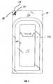
- FIGS. 1-2illustrate a suture package depicted generally as reference numeral 10.
- Suture package 10includes envelope 50, outer jacket 100 and inner retainer 200 which is secured within the outer jacket 100.
- Envelope 50receives outer jacket 100 and inner retainer 200 when the outer jacket 100 and the inner retainer 200 are in their respective folded conditions.
- envelope 50is removed.
- Envelope 50includes top sheet 52 and bottom sheet 54.
- Top sheet 52may be formed of a clear plastic, such as a polyethylene, or other like material.
- Bottom sheet 54may be constructed from paperboard, fiberboard, Tyvek®, aluminum foil or other like material. The materials of construction of top and bottom sheets 52, 54 preferably prevent or greatly impede the transmission of moisture therethrough.
- Top sheet 52 and bottom sheet 54are generally rectangular in shape and substantially the same size. Sheets 52, 54 are adhered together along their respective peripheries by an adhesive, cement, etc. or the like. In one preferred embodiment, a peripheral line of peelable adhesive is used. Sheets 52, 54 define flaps 56, 58 at one corner, which are devoid of adhesive.
- Flaps 56, 58remain unattached to be readily grasped by the operator to facilitate at least partial separation of sheets 52, 54 when opening envelope 50.
- Envelope 50hermetically seals outer jacket 100 and inner retainer 200, preventing contaminates from reaching the stored sutures 300 and, as mentioned above, minimizing passage of moisture.
- Outer jacket 100is visible through top sheet 52 of envelope 50 as depicted in FIG. 1 .
- Outer jacket 100defines inner pocket 102 when in the folded condition to receive folded inner retainer 200.
- outer jacket 100is shown in a flat, unfolded or pre-folded state.
- Outer jacket 100may be constructed from paperboard, fiberboard, cardboard or any other fibrous material such as Tyvek®, or like material.
- Outer jacket 100is preferably die cut to form a series of interconnected panels.
- outer jacket 100includes panels 110,120, 130 and top panel 140. Panels 110, 120, 130 are generally rectangular in shape and substantially the same size.
- Panels 110,120, 130each have respective opposed major sides 112,122, 132 also referred to as longitudinal edges with reference to reference longitudinal axis "x", and respective opposed minor sides 114, 124, 134, also referred to as transverse edges.
- Centrally positioned panel 110includes a foam strip 150 adjacent its lower minor side 114.
- Foam strip 150functions as a stop when inner retainer 200 is inserted within pocket 102 of folded outer jacket 100.
- Foam strip 150may also maintain the folded panels 120, 130 a desired or predetermined distance from centrally positioned panel 110.
- Panel 130includes longitudinal slot 136 along one major side 132 adjacent centrally positioned panel 110.
- Panel 120includes tab 126 formed therein. Tab 126 is dimensioned to cooperate with longitudinal slot 136 to releasably secure panels 110, 130 thereby securing the panels 110, 120, 130 a folded condition.
- Gussets 160, 170respectively interconnect panels 120, 130 and centrally positioned panel 110.
- Gussets 160, 170are substantially triangular in shape tapering inwardly toward the lower end of outer jacket 110. Gussets 160, 170 prevent panels 120, 130 from collapsing onto, and contacting panel 110 when the panels 120, 130 are folded onto the panel 110. Gussets 160, 170 also provide depth to the folded outer jacket 100 thereby increasing the size of pocket 102 formed by folded panels 110, 120, 130.
- Gussets 160, 170define double fold lines corresponding to major sides 112, 122, 132 about which panels 120, 130 fold onto centrally positioned panel 110.
- gussets 160, 170ensures that pocket 102 has a greater depth adjacent the upper or open end of outer jacket 100 and a lesser depth toward the lower end of outer jacket 100. This arrangement permits folded inner retainer 200 to be readily inserted into pocket 102 while ensuring that the inner retainer 200 is frictionally engaged within the pocket 102 adjacent the lower end of the outer jacket 100.
- top panel 140is foldably connected to panel 120 along upper minor side 124 of the panel 120.
- top panel 140may be folded backwards to expose the contents within outer jacket 100.
- Top panel 140includes intermediate fold line 142 which thereby defines upper top panel portion 144 and lower top panel portion 146.
- Top panel portion 144is adapted to fold along fold line 142 onto top panel portion 146 to enclose the pocket 102 defined by outer jacket 100.
- Top panel portion 144includes arcuate slit 148 which is configured and dimensioned to receive upper minor side 114 of panel 110 or upper minor side 134 of panel 130 to secure top panel 140 in a folded condition.
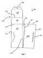
- FIG. 3illustrates the process of folding outer jacket 100 to form pocket 102 for receiving inner retainer 200.
- panel 130is folded along major side 132 onto panel 110 such that the rear surface 130a of the panel 130 is exposed as depicted in FIG. 4 .
- panel 120is folded along major side 122 onto panels 110, 130 such that rear surface 120a of the panel 120 is exposed as shown in FIG. 5 .
- panels 110, 130may be folded onto panel 120.
- tab 126 of panel 120is then inserted into slot 136 of panel 130 to releasably secure the panels 120, 130.
- FIG. 6illustrates the front side of outer jacket 100 with top panel 140 in an open position and pocket 102 accessible for reception of the folded inner retainer 200.
- Inner retainer 200is shown in a flat, unfolded or pre-folded state.
- Inner retainer 200is constructed from paper or any other like material identified hereinabove in connection with outer jacket 100.
- Inner retainer 200includes a first or central row of support panels, namely, centrally positioned main support panel 210, and side support panels 212, 214 on each side of the main support panel 210.
- Main support panel 210defines openings 216 adjacent upper and lower minor sides 218 of the main support panel 210. Openings 216 are sized and configured to receive winding pins or pegs of a winding device (not shown).
- Sutures 300may be wound about the winding pins either manually or through automated means.
- Main support panel 210is generally rectangular in configuration defining major sides 220 and minor sides 218.
- Side support panels 212, 214are generally trapezoidal in shaped and have major sides 222 which are interconnected to major sides 220 of main support panel 210 through gusset 224.
- Gussets 224define double fold lines corresponding to major sides 220, 222 about which side support panels 212, 214 fold onto main support panel 210. Gussets 224 increase the depth of the folded support panels to thereby provided sufficient space to store sutures 300.
- Inner retainer 200further includes cover panel 230 which forms a second row of panels of the inner retainer 200.
- Cover panel 230includes minor side 232 which is connected to upper minor side 218 of main support panel 210 through gusset 234.
- Gusset 234defines a double fold line about which panel 230 folds onto main support panel 210.
- Cover panel 230may have suture receiving slot 236 extending from a peripheral edge (e.g., major side 238) of the cover panel 230 into the central area of the cover panel 230.
- Suture receiving slot 234may be utilized to receive end portions of sutures 300 to assist supporting the suture end portions and attached needles 400 within inner retainer 200 as will be discussed.
- suture receiving slot 236may receive suture clip 500 which is attached to the end portions of sutures 300.
- cover panel 230may be devoid of suture receiving slot 236.
- Inner retainer 200further includes a third row of closure panels, namely, central closure panel 240 and a pair of side closure panels 242, 244 connected to the central closure panel 240.
- Central closure panel 240is connected along minor side 246 to minor side 218 of main support panel 210 through gusset 248. Gusset 248 defines a double fold line about which central panel 242 folds onto main support panel 210.
- Central closure panel 242defines an arcuate or recessed lower minor side 250. The recessed configuration of minor side 250 assists in exposing the stored needles 400 of the assembled package as will be discussed.
- Central closure panel 242further defines major sides 252.
- Side closure panels 242, 244include major sides 254, 256, and are connected to central closure panel 242 through gussets 258, 260 respectively.
- Gussets 258, 260each define double fold lines.
- Side closure panels 242, 244include tabs 262 and slots 264 respectively. Slots 264 of side panel 244 are sized to receive tabs 262 of side panel 242 to facilitate retaining the side closure panels 242, 244 in a folded condition.
- pre-folded inner retainer 200is placed on a winding device such that openings 216 are aligned with and receive winding pegs of the winding device (not shown).
- Individual sutures 300 with attached needles 400are wound around the winding pegs either manually or through an automated suture winding process.
- Sutures 300may be wrapped around the winding pegs collectively as a bundle, or individually.
- sutures 300have suture clip 500 attached to the suture end portions 302 adjacent needles 400.
- Suture clip 500retains the sutures in a bundle and preferably in spaced relation to minimize tangling of the suture ends 302.
- Suture clip 500also permits sutures 300 to be removed from inner retainer 200 as a bundle rather than as individual sutures. Suture clip 500 may be attached to the individual sutures 300 prior to or subsequent to the winding process.
- suture clip 500includes resilient finger 502. Resilient finger 502 may be displaced or pivoted away from suture clip 500 as shown by directional arrow "p" to receive sutures 300. Preferably, finger 502 has sufficient resiliency to return to its normal position to frictionally engage sutures 300.
- Other arrangements for suture clip 500are also envisioned including separately mounted clamps, an aperture, a slit extending through the suture clip 500, etc.
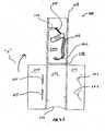
- FIG. 7illustrates side support panel 212 in their folded conditions on central support panel 210.
- gussets 224provide sufficient depth to the folded support panels 210, 212, 214 to accommodate the loaded sutures 300.
- cover panel 230is folded onto main support panel 210 to cover the wound sutures 300 with the exception of the suture end portions 302 adjacent the attached needles 400 and suture clip 500.
- Suture clip 500 and attached needles 400are preferably positioned on the rear side 230a of cover panel 230 and preferably hung in suspension over minor side 218 of main support panel 210.
- clip 500may be manipulated to engage suture receiving slot 236 of cover panel 230.
- individual suture portions 304 on the side of suture clip 500 away from needles 400are passed through suture receiving slot 236 of cover panel 230 and cover panel 230 is folded onto main support panel 210 as depicted in FIG. 9A . In this manner, suture receiving slot 236 supports the individual sutures 300 with attached needles 400 and suture clip 500 in suspended manner against rear side 230a of cover panel 230.
- FIG. 10illustrates central closure panel 240 in the folded condition.
- the rear side 210a of needle support panel 210is shown.
- Side closure panels 242, 244are then folded around main support panel side 210 and tabs 262 are inserted within slots 264 to secure the side closure panels 242, 244 together as depicted in FIG. 11 .
- suture clip 500is manipulated to hang over the arcuate minor side 250 to provide enhanced access to the suture clip 250, and attached needles 400 and sutures 300 as depicted in FIG. 12 .
- inner retainer 200is then positioned within pocket 102 of outer jacket 100 and advanced to a position where the outer jacket 100 frictionally engages the inner retainer 200 and/or the inner retainer 200 abuts foam strip 150.
- Top panel portion 144is folded along fold line 142 onto top panel portion 146. In the folded position, tab 148 of panel portion 144 engages the top minor side 114 of panel 110, thus securing inner retainer 200 within outer jacket 100.
- inner retainer 200, securely contained within outer jacket 100is sealed within outer envelope 50.
- outer envelope 50is opened by separating flaps 54, 56.
- tab 148 of cover panel 140is disengaged from the top minor side 114 of panel 110 and panel 140 is folded back along fold line 124.
- Inner retainer 200is then removed from pocket 102 of outer jacket 100.
- Panels 242, 244are then unfolded first by disengaging tabs 262 of panel 242 from slots 264 of panel 244.
- Suture bundle 300is thus accessible and may be removed as a bundle using suture clip 500. Removal of the sutures 300 as a bundle greatly minimizes the potential of suture tangling which would otherwise exist if the sutures were removed individually. If desired, the remainder of inner retainer 200 may be unfolded prior to removing the sutures 300.
Landscapes
- Health & Medical Sciences (AREA)
- Surgery (AREA)
- Life Sciences & Earth Sciences (AREA)
- Biomedical Technology (AREA)
- Nuclear Medicine, Radiotherapy & Molecular Imaging (AREA)
- Engineering & Computer Science (AREA)
- Dentistry (AREA)
- Heart & Thoracic Surgery (AREA)
- Medical Informatics (AREA)
- Molecular Biology (AREA)
- Animal Behavior & Ethology (AREA)
- General Health & Medical Sciences (AREA)
- Public Health (AREA)
- Veterinary Medicine (AREA)
- Surgical Instruments (AREA)
Description
- The present disclosure relates generally to surgical suture packaging, and, more particularly, relates to a foldable suture package for retaining at least one suture.
- Surgical packages for sutures with attached needles are widely known in the art. Two commonly used suture packages include a molded plastic retainer and a folded paper retainer. A conventional molded plastic retainer incorporates a molded channel, e.g., a racetrack channel, for receiving a plurality of sutures and a needle park for mounting the needles attached to the sutures. The folded paper retainer is generally constructed from paperboard, fiberboard or other suitable material, and incorporates a plurality of panels which are folded to form an envelope in which the wound suture(s) is placed.
- While molded plastic retainers can receive a number of sutures with attached needles of various sizes, the folded paper retainers are generally more cost effective and less wasteful than the plastic retainers. However, drawbacks of conventional folded paper retainers include difficulties in opening the retainer, and in accessing and removing the stored sutures. In addition, if several sutures are stored in a folded paper retainer, these sutures have a tendency to tangle if provisions are not made to maintain the sutures separated.
- Examples of suture retainers in the form of folded panels of paper can be seen in
US-A-2004/0020795 ,US-A-4369880 andUS-A-5871089 , as well as inDE-A-197 06 729 . A folded paper retainer for a reel dispenser of suture material is disclosed inUS-A-5460263 . - The invention is defined in claim 1 below. The dependent claims are directed to optional features and preferred embodiments. The present disclosure relates to improvements in surgical suture packaging. A surgical suture package for storing at least one surgical suture includes an outer jacket having a plurality of panels foldably connected to each other and adapted to fold upon each other to form an inner pocket and an inner retainer for positioning within the pocket of the outer jacket. The suture package also includes an outer envelope which defines a pouch for receiving the inner retainer member and the outer jacket in the folded conditions thereof. The inner retainer includes a row of support panels having a main support panel for supporting the at least one suture, and a pair of side support panels foldably connected to the main support panel along respective opposed major sides of the main support panel. The side support panels are adapted to be folded onto the main support panel to enclose the at least one suture. A cover panel is foldably connected to the main support panel along a minor side of the main support panel, and is adapted to be folded onto the support panels. A row of closure panels including a main closure panel is foldably connected to the main support panel along a second minor side of the main closure panel, and a pair of side closure panels is foldably connected to the main closure panel along respective opposed major sides of the main closure panel. The main closure panel is adapted to be folded along the second minor side of the main support panel onto the main support panel and the side closure panels are adapted to be folded along the major sides of the main closure panel to enclose the support and cover panels.
- Means may be provided, for retaining the side closure panels in a folded condition enclosing the support and cover panels. Alternatively, the side closure panels include a tab and slot arrangement for releasably retaining the side closure panels in a folded condition enclosing the support and cover panels.
- The outer jacket includes at least two outer panels foldably connected to each other to define the pocket. Preferably, the outer jacket includes a row of three outer panels foldably connected to each other to define the pocket. The outer panels include a central outer panel and side outer panels foldably connected to respective major sides of the central outer panel. The side outer panels include a tab and slot arrangement for retaining the outer panels in a folded condition. The side outer panels may be each connected to the central outer panel through a gusset. The outer jacket further may include a top panel connected to a minor side of one of the side outer panels. The top panel is adapted to fold along an intermediate fold line thereof to substantially enclose the pocket formed by the outer enclosure. The top panel may include a locking slit dimensioned to receive a minor side of the other of the side panel or central outer panel.
- The cover panel of the inner retainer may include a suture receiving slot for receiving and supporting a suture end portion of the at least one suture. Alternatively, a suture clip is attachable to the at least one suture. A plurality of sutures may be supported within the inner retainer whereby the suture clip is connected to each end portion of the sutures.
- In another preferred embodiment, a suture package for a plurality of surgical needled sutures includes first and second rows of panels. The first row includes a main support panel for supporting a plurality of needled sutures, and a pair of side support panels foldably connected to the main support panel along respective opposed major sides of the main support panel, whereby the side support panels are adapted to be folded onto the main support panel to enclose the sutures. The second row includes a cover panel foldably connected to the main support panel along a first minor side of the main support panel and adapted to be folded onto the support panels. A suture clip is attachable to each of the suture end portions, preferably, proximal of the needles to permit concurrent removal of the sutures from the support panels.
- The suture package may include a third row having a plurality of closure panels. The closure panels include a main closure panel foldably connected to the main support panel along a second minor side of the main closure panel, and a pair of side closure panels foldably connected to the main closure panel along respective opposed major sides of the main closure panel. The main closure panel is adapted to be folded along the second minor side of the main support panel onto the cover panel and the side closure panels are adapted to be folded along the major sides of the main closure panel to enclose the support and cover panels.
- An outer jacket is of necessity provided. The outer jacket has at least two outer panels foldably connected to each other and adapted to fold upon each other to form an inner pocket. The inner pocket is adapted to at least partially accommodate the support, cover and closure panels in a folded condition thereof. The outer jacket preferably includes three panels.
- A method of packaging a plurality of sutures is also disclosed.
- Preferred embodiments of the present disclosure will be better appreciated by reference to the drawings wherein:
FIG. 1 is a front plan view of a suture package including an envelope, a foldable outer jacket and a foldable inner retainer ;FIG. 2 is a front plan view of the outer jacket with the inner retainer positioned within the pocket of the outer jacket;FIG. 3 is a front plan view of the outer jacket in an unfolded condition;FIGS. 4-6 are plan views illustrating the preferred sequence of folding the outer jacket to form the pocket;FIG. 7 is a front plan view of the inner retainer in an unfolded condition; andFIGS 8-12 are plan views illustrating the preferred sequence of loading and folding the inner retainer to form a suture compartment for a plurality of sutures.- Referring now to the drawings wherein like reference numerals illustrate similar components throughout the several views,
FIGS. 1-2 illustrate a suture package depicted generally as reference numeral 10. Suture package 10 includesenvelope 50,outer jacket 100 andinner retainer 200 which is secured within theouter jacket 100. Envelope 50 receivesouter jacket 100 andinner retainer 200 when theouter jacket 100 and theinner retainer 200 are in their respective folded conditions. InFIG. 2 ,envelope 50 is removed. Envelope 50 includestop sheet 52 andbottom sheet 54.Top sheet 52 may be formed of a clear plastic, such as a polyethylene, or other like material.Bottom sheet 54 may be constructed from paperboard, fiberboard, Tyvek®, aluminum foil or other like material. The materials of construction of top andbottom sheets Top sheet 52 andbottom sheet 54 are generally rectangular in shape and substantially the same size.Sheets Sheets flaps Flaps sheets envelope 50.Envelope 50 hermetically sealsouter jacket 100 andinner retainer 200, preventing contaminates from reaching the storedsutures 300 and, as mentioned above, minimizing passage of moisture.Outer jacket 100 is visible throughtop sheet 52 ofenvelope 50 as depicted inFIG. 1 .- With reference to
FIGS. 2-3 ,outer jacket 100 will be discussed.Outer jacket 100 definesinner pocket 102 when in the folded condition to receive foldedinner retainer 200. InFIG. 3 ,outer jacket 100 is shown in a flat, unfolded or pre-folded state.Outer jacket 100 may be constructed from paperboard, fiberboard, cardboard or any other fibrous material such as Tyvek®, or like material.Outer jacket 100 is preferably die cut to form a series of interconnected panels. Specifically,outer jacket 100 includes panels 110,120, 130 andtop panel 140.Panels minor sides panel 110 includes a foam strip 150 adjacent its lowerminor side 114. Foam strip 150 functions as a stop wheninner retainer 200 is inserted withinpocket 102 of foldedouter jacket 100. Foam strip 150 may also maintain the foldedpanels 120, 130 a desired or predetermined distance from centrally positionedpanel 110.Panel 130 includeslongitudinal slot 136 along onemajor side 132 adjacent centrally positionedpanel 110.Panel 120 includestab 126 formed therein.Tab 126 is dimensioned to cooperate withlongitudinal slot 136 to releasablysecure panels panels Gussets panels panel 110.Gussets outer jacket 110.Gussets panels panel 110 when thepanels panel 110.Gussets outer jacket 100 thereby increasing the size ofpocket 102 formed by foldedpanels Gussets major sides panels panel 110. The triangular or tapering configuration ofgussets pocket 102 has a greater depth adjacent the upper or open end ofouter jacket 100 and a lesser depth toward the lower end ofouter jacket 100. This arrangement permits foldedinner retainer 200 to be readily inserted intopocket 102 while ensuring that theinner retainer 200 is frictionally engaged within thepocket 102 adjacent the lower end of theouter jacket 100.- With continued reference to
FIGS. 2-3 ,top panel 140 is foldably connected topanel 120 along upperminor side 124 of thepanel 120. In this regard,top panel 140 may be folded backwards to expose the contents withinouter jacket 100.Top panel 140 includesintermediate fold line 142 which thereby defines uppertop panel portion 144 and lowertop panel portion 146.Top panel portion 144 is adapted to fold alongfold line 142 ontotop panel portion 146 to enclose thepocket 102 defined byouter jacket 100.Top panel portion 144 includesarcuate slit 148 which is configured and dimensioned to receive upperminor side 114 ofpanel 110 or upperminor side 134 ofpanel 130 to securetop panel 140 in a folded condition. - The process of folding
outer jacket 100 to formpocket 102 for receivinginner retainer 200 will be described in detail. Initially, with reference toFIG. 3 ,panel 130 is folded alongmajor side 132 ontopanel 110 such that the rear surface 130a of thepanel 130 is exposed as depicted inFIG. 4 . Thereafter,panel 120 is folded alongmajor side 122 ontopanels panel 120 is exposed as shown inFIG. 5 . (Alternatively,panels panel 120.) Withpanels tab 126 ofpanel 120 is then inserted intoslot 136 ofpanel 130 to releasably secure thepanels FIG. 6 illustrates the front side ofouter jacket 100 withtop panel 140 in an open position andpocket 102 accessible for reception of the foldedinner retainer 200. - Referring now to
FIG. 7 ,inner retainer 200 will be discussed.Inner retainer 200 is shown in a flat, unfolded or pre-folded state.Inner retainer 200 is constructed from paper or any other like material identified hereinabove in connection withouter jacket 100.Inner retainer 200 includes a first or central row of support panels, namely, centrally positionedmain support panel 210, andside support panels main support panel 210.Main support panel 210 definesopenings 216 adjacent upper and lowerminor sides 218 of themain support panel 210.Openings 216 are sized and configured to receive winding pins or pegs of a winding device (not shown).Sutures 300 may be wound about the winding pins either manually or through automated means.Main support panel 210 is generally rectangular in configuration definingmajor sides 220 andminor sides 218.Side support panels major sides 222 which are interconnected tomajor sides 220 ofmain support panel 210 throughgusset 224.Gussets 224 define double fold lines corresponding tomajor sides side support panels main support panel 210.Gussets 224 increase the depth of the folded support panels to thereby provided sufficient space to storesutures 300. Inner retainer 200 further includescover panel 230 which forms a second row of panels of theinner retainer 200.Cover panel 230 includesminor side 232 which is connected to upperminor side 218 ofmain support panel 210 throughgusset 234.Gusset 234 defines a double fold line about whichpanel 230 folds ontomain support panel 210.Cover panel 230 may havesuture receiving slot 236 extending from a peripheral edge (e.g., major side 238) of thecover panel 230 into the central area of thecover panel 230. Suture receivingslot 234 may be utilized to receive end portions ofsutures 300 to assist supporting the suture end portions and attachedneedles 400 withininner retainer 200 as will be discussed. Alternatively, suture receivingslot 236 may receivesuture clip 500 which is attached to the end portions ofsutures 300. As a further alternative,cover panel 230 may be devoid ofsuture receiving slot 236.Inner retainer 200 further includes a third row of closure panels, namely,central closure panel 240 and a pair ofside closure panels central closure panel 240.Central closure panel 240 is connected alongminor side 246 tominor side 218 ofmain support panel 210 throughgusset 248.Gusset 248 defines a double fold line about whichcentral panel 242 folds ontomain support panel 210.Central closure panel 242 defines an arcuate or recessed lowerminor side 250. The recessed configuration ofminor side 250 assists in exposing the storedneedles 400 of the assembled package as will be discussed.Central closure panel 242 further definesmajor sides 252.Side closure panels major sides central closure panel 242 throughgussets Gussets Side closure panels tabs 262 andslots 264 respectively.Slots 264 ofside panel 244 are sized to receivetabs 262 ofside panel 242 to facilitate retaining theside closure panels - The preferred sequence of loading
inner retainer 200 withsutures 300 and folding theinner retainer 200 will be discussed. Initially, pre-foldedinner retainer 200 is placed on a winding device such thatopenings 216 are aligned with and receive winding pegs of the winding device (not shown).Individual sutures 300 with attachedneedles 400 are wound around the winding pegs either manually or through an automated suture winding process.Sutures 300 may be wrapped around the winding pegs collectively as a bundle, or individually. Preferably, sutures 300 havesuture clip 500 attached to thesuture end portions 302adjacent needles 400.Suture clip 500 retains the sutures in a bundle and preferably in spaced relation to minimize tangling of the suture ends 302.Suture clip 500 also permitssutures 300 to be removed frominner retainer 200 as a bundle rather than as individual sutures.Suture clip 500 may be attached to theindividual sutures 300 prior to or subsequent to the winding process. In one preferred embodiment depicted inFIG. 7A ,suture clip 500 includesresilient finger 502.Resilient finger 502 may be displaced or pivoted away fromsuture clip 500 as shown by directional arrow "p" to receivesutures 300. Preferably,finger 502 has sufficient resiliency to return to its normal position to frictionally engage sutures 300. Other arrangements forsuture clip 500 are also envisioned including separately mounted clamps, an aperture, a slit extending through thesuture clip 500, etc. Oncesutures 300 have been wound onto the winding pegs, the winding pegs may be removed andinner retainer 200 may be folded. - Once
sutures 300 are in position supported bycentral support panel 210 as shown inFIG. 7 ,side support panel 212 is folded along the double fold line sides defined bygusset 220 onto thecentral support panel 210.Side support panel 214 is then along the double fold line defined bygusset 224 onto the rear side 212a ofside support panel 212 to expose the rear side 214a of theside support panel 214.FIG. 8 illustratesside support panels central support panel 210. As appreciated,gussets 224 provide sufficient depth to the foldedsupport panels - With reference to
FIG. 9 ,cover panel 230 is folded ontomain support panel 210 to cover the wound sutures 300 with the exception of thesuture end portions 302 adjacent the attachedneedles 400 andsuture clip 500.Suture clip 500 and attachedneedles 400 are preferably positioned on the rear side 230a ofcover panel 230 and preferably hung in suspension overminor side 218 ofmain support panel 210. In the alternative,clip 500 may be manipulated to engagesuture receiving slot 236 ofcover panel 230. As a further alternative,individual suture portions 304 on the side ofsuture clip 500 away fromneedles 400 are passed throughsuture receiving slot 236 ofcover panel 230 andcover panel 230 is folded ontomain support panel 210 as depicted inFIG. 9A . In this manner,suture receiving slot 236 supports theindividual sutures 300 with attachedneedles 400 andsuture clip 500 in suspended manner against rear side 230a ofcover panel 230. - Once
cover panel 230 is in position,central closure panel 240 is folded in the direction of the arrow "a" ofFIG. 9 along the double fold line provided bygusset 248 onto the rear side 230a ofcover panel 230.FIG. 10 illustratescentral closure panel 240 in the folded condition. InFIG. 10 , the rear side 210a ofneedle support panel 210 is shown.Side closure panels support panel side 210 andtabs 262 are inserted withinslots 264 to secure theside closure panels FIG. 11 . Preferably,suture clip 500 is manipulated to hang over the arcuateminor side 250 to provide enhanced access to thesuture clip 250, and attachedneedles 400 andsutures 300 as depicted inFIG. 12 . - Referring again to
FIG. 2 ,inner retainer 200 is then positioned withinpocket 102 ofouter jacket 100 and advanced to a position where theouter jacket 100 frictionally engages theinner retainer 200 and/or theinner retainer 200 abuts foam strip 150.Top panel portion 144 is folded alongfold line 142 ontotop panel portion 146. In the folded position,tab 148 ofpanel portion 144 engages the topminor side 114 ofpanel 110, thus securinginner retainer 200 withinouter jacket 100. Finally,inner retainer 200, securely contained withinouter jacket 100, is sealed withinouter envelope 50. - In order to access
suture bundle 300,outer envelope 50 is opened by separatingflaps tab 148 ofcover panel 140 is disengaged from the topminor side 114 ofpanel 110 andpanel 140 is folded back alongfold line 124.Inner retainer 200 is then removed frompocket 102 ofouter jacket 100.Panels tabs 262 ofpanel 242 fromslots 264 ofpanel 244.Suture bundle 300 is thus accessible and may be removed as a bundle usingsuture clip 500. Removal of thesutures 300 as a bundle greatly minimizes the potential of suture tangling which would otherwise exist if the sutures were removed individually. If desired, the remainder ofinner retainer 200 may be unfolded prior to removing thesutures 300. - It will be understood that various modifications may be made to the embodiments disclosed herein. Therefore, the above description should not be construed as limiting, but merely as exemplifications of preferred embodiments. Those skilled in the art will envision other modifications within the scope of the claims below.
Claims (14)
- A surgical suture package (10) for storing at least one surgical suture (300), which comprises:an outer jacket (100) including a plurality of panels foldably connected to each other and adapted to fold upon each other to form an inner pocket (102);an inner retainer (200) for positioning within the pocket of the outer jacket, and for removal from the pocket when access to the suture is required andan outer envelope (50), the outer envelope defining a pouch for receiving the inner retainer member and the outer jacket in the folded conditions thereof; andthe inner retainer including:a row of support panels, the support panels including a main support panel (210) for supporting the at least one suture (300), and a pair of side support panels (212, 214) foldably connected to the main support panel along respective opposed major sides (220, 222) of the main support panel, whereby the side support panels are adapted to be folded onto the main support panel to enclose the at least one suture;a cover panel (230) foldably connected to the main support panel along a minor side (232) of the main support panel, the cover panel being adapted to be folded onto the support panels; anda row of closure panels, the closure panels including a main closure panel (240) foldably connected to the main support panel along a second minor side (246) of the main closure panel, and a pair of side closure panels foldably connected to the main closure panel along respective opposed major sides (254, 256) of the main closure panel, whereby the main closure panel is adapted to be folded along the second minor side of the main support panel onto the main support panel and the side closure panels are adapted to be folded along the major sides of the main closure panel to enclose the support and cover panels.
- The suture package according to claim 1, including means (262, 264) for retaining the side closure panels in a folded condition enclosing the support and cover panels.
- The suture package according to claim 2, wherein the means for retaining the side closure panels comprise a tab (262) and slot (264) arrangement for releasably retaining the side closure panels in a folded condition enclosing the support and cover panels.
- The suture package according to claim 1, 2 or 3, wherein the outer jacket includes at least two outer panels (110, 120, 130) foldably connected to each other to define the pocket.
- The suture package according to claim 4, wherein the outer jacket includes a row of three outer panels foldably connected to each other to define the pocket, the outer panels including a central outer panel (110) and side outer panels (120, 130) foldably connected to respective major sides of the central outer panel.
- The suture package according to claim 5, wherein the side outer panels includes a tab (126) and slot (136) arrangement for retaining the outer panels in a folded condition.
- The suture package according to claim 5 or 6, wherein the side outer panels are each connected to the central outer panel through a gusset (160, 170).
- The suture package according to any one of the preceding claims, wherein the outer jacket includes a top panel (140) connected to a minor side (124) of one of the side outer panels, the top panel adapted to fold along an intermediate fold line (142) thereof to substantially enclose the pocket formed by the outer enclosure.
- The suture package according to claim 8, wherein the top panel includes a locking slit (148) dimensioned to receive a minor side (124, 114) of the other of the side panel or central outer panel.
- The suture package according to any one of the preceding claims, wherein the cover panel includes a suture receiving slot (236) for receiving and supporting a suture end portion of the at least one suture.
- The suture package according to any one of the preceding claims, including a suture clip (500) attachable to the at least one suture.
- The suture package according to claim 11, including a plurality of sutures supported within the inner retainer, the suture clip being connected to each end portion (302) of the sutures.
- A method of packaging at least one suture, the method comprising the steps of:providing an inner retainer member including:a row of support panels having a main support panel and a pair of side support panels foldably connected to the main support panel along respective opposed major edges of the main support panel; anda cover panel foldably connected to the main support panel along a minor edge of the main support panel;placing a plurality of sutures on the main support panel of the row of support panels;attaching a suture clip to each suture end portion of the sutures;folding the side support panels along the major edges onto the main support panel to enclose the sutures;folding the cover panel along the minor edge of the main support panel whereby the cover panel covers the support panels;positioning the suture end portions and the suture clip adjacent a rear side of the support panel such that the suture end portions and the suture clip are accessible, wherein the inner retainer member includes a row of closure panels, the closure panels including a main closure panel foldably connected to the main support panel along a second minor edge of the main closure panel, and a pair of side closure panels foldably connected to the main closure panel along respective opposed major edges of the main closure panel and further including the step of folding the main closure panel along the second minor edge of the main support panel onto the main support panel and folding the side closure panels along the major edges of the main closure panel to enclose the support and cover panels;providing an outer jacket, the outer jacket including a plurality of outer panels foldably connected to each other to define a pocket;positioning the inner retainer member in a folded condition within the pocket of the outer jacket;providing an outer envelope (50), the outer envelope defining a pouch for receiving the inner retainer member and the outer jacket in the folded conditions thereof; andpositioning the inner retainer member and the outer jacket in a folded condition within the pouch of the outer enveloppe.
- The method according to claim 13, wherein the step of placing includes winding a plurality of sutures on the main support panel.
Applications Claiming Priority (1)
| Application Number | Priority Date | Filing Date | Title |
|---|---|---|---|
| US11/396,776US7600634B2 (en) | 2006-04-03 | 2006-04-03 | Packaging for surgical sutures |
Publications (3)
| Publication Number | Publication Date |
|---|---|
| EP1842492A2 EP1842492A2 (en) | 2007-10-10 |
| EP1842492A3 EP1842492A3 (en) | 2008-05-21 |
| EP1842492B1true EP1842492B1 (en) | 2010-06-02 |
Family
ID=38326024
Family Applications (1)
| Application Number | Title | Priority Date | Filing Date |
|---|---|---|---|
| EP07005462ANot-in-forceEP1842492B1 (en) | 2006-04-03 | 2007-03-16 | Packaging for surgical sutures |
Country Status (7)
| Country | Link |
|---|---|
| US (3) | US7600634B2 (en) |
| EP (1) | EP1842492B1 (en) |
| JP (2) | JP2007275568A (en) |
| AU (1) | AU2007201304A1 (en) |
| CA (1) | CA2582637A1 (en) |
| DE (1) | DE602007006854D1 (en) |
| ES (1) | ES2344807T3 (en) |
Families Citing this family (23)
| Publication number | Priority date | Publication date | Assignee | Title |
|---|---|---|---|---|
| WO2008150773A1 (en)* | 2007-05-29 | 2008-12-11 | Angiotech Pharmaceuticals, Inc. | Suture packaging |
| EP2205163B1 (en)* | 2007-09-10 | 2018-12-12 | Ethicon, LLC | Suture packaging and methods related thereto |
| CA2740640C (en)* | 2010-05-20 | 2018-09-04 | Honeywell International Inc. | Emergency rope bail-out bag |
| EP3155978B1 (en) | 2010-06-11 | 2022-04-13 | Cilag GmbH International | Suture delivery tools for endoscopic and robot-assisted surgery |
| USD657124S1 (en) | 2010-06-22 | 2012-04-10 | Ethicon, Inc. | Box for medical implants |
| US8517174B2 (en) | 2010-06-22 | 2013-08-27 | Ethicon, Inc. | Dispensing packages for medical devices having two components that are mechanically interlocked and methods therefor |
| US8540139B2 (en) | 2010-06-22 | 2013-09-24 | Ethicon, Inc. | Outer boxes for storing and delivering medical devices used during surgical procedures and methods therefor |
| JP6013352B2 (en) | 2010-11-09 | 2016-10-25 | エシコン・エルエルシーEthicon LLC | Emergency indwelling suture and package |
| USD666805S1 (en)* | 2011-11-03 | 2012-09-11 | Ferguson Arlene H | Post-mastectomy drainage tube carrier |
| US20130341123A1 (en)* | 2012-06-21 | 2013-12-26 | Vincent McMahon | Emergency device with quick release hook |
| US9439752B2 (en) | 2014-03-28 | 2016-09-13 | Medos International Sàrl | Implant and filament management device |
| BR102015007027B1 (en) | 2014-03-28 | 2022-02-08 | Medos International Sàrl | IMPLANT AND FILAMENT MANAGEMENT DEVICE |
| DE102014114042A1 (en)* | 2014-09-26 | 2016-03-31 | Eckart Frimberger | Packaging with a medical instrument arranged therein |
| US9776783B2 (en) | 2015-06-04 | 2017-10-03 | Covidien Lp | Foldable sleeve for surgical instrument |
| US10004567B2 (en)* | 2016-09-15 | 2018-06-26 | Ethicon, Inc. | Sterile packaging systems for medical devices |
| USD826043S1 (en) | 2016-11-11 | 2018-08-21 | Ethicon, Inc. | Medical device folder |
| US11622762B2 (en)* | 2019-07-02 | 2023-04-11 | Conmed Corporation | Implant and suture organization device |
| US20220346778A1 (en)* | 2021-04-29 | 2022-11-03 | Origami Surgical, Inc. | Housing for storing sutures therein, and methods of use therefor |
| US11678961B2 (en)* | 2021-06-04 | 2023-06-20 | The Autoflosser LLC | Packaging for lengths of dental floss |
| US12186268B2 (en) | 2022-01-20 | 2025-01-07 | Cryoport, Inc. | Foldable cassette bags for transporting biomaterials |
| US11691788B1 (en) | 2022-01-20 | 2023-07-04 | Cryoport, Inc. | Foldable cassette bags for transporting biomaterials |
| US12280008B2 (en) | 2022-04-07 | 2025-04-22 | Cryoport, Inc. | Systems and devices for transporting biomaterials |
| US12383465B2 (en) | 2022-06-29 | 2025-08-12 | Cryoport, Inc. | Cassette bags for transporting biomaterials |
Family Cites Families (107)
| Publication number | Priority date | Publication date | Assignee | Title |
|---|---|---|---|---|
| US301801A (en)* | 1884-07-08 | And forming the heads and faces | ||
| US3162307A (en)* | 1963-07-10 | 1964-12-22 | Ethicon Inc | Surgical package |
| FR1404779A (en)* | 1964-07-09 | 1965-07-02 | Ethicon Inc | Sterile surgical packaging |
| JPS5549789Y2 (en)* | 1974-06-18 | 1980-11-20 | ||
| US3951261A (en)* | 1974-08-28 | 1976-04-20 | Ethicon, Inc. | Needled suture mounting and dispensing device and package |
| US4142628A (en)* | 1977-05-16 | 1979-03-06 | American Cyanamid Company | Direct dispensing suture package for a multiple of sterile surgical sutures with or without needles attached |
| USD272600S (en)* | 1980-12-12 | 1984-02-14 | Kubas Robert J | Suture package |
| US4369880A (en)* | 1981-03-06 | 1983-01-25 | Howmedica, Inc. | Pop-up armed suture |
| US4574948A (en)* | 1981-03-06 | 1986-03-11 | Howmedica, Inc. | Linear fold armed suture |
| US4412614A (en)* | 1982-02-16 | 1983-11-01 | Ethicon, Inc. | Three panel needled suture holder |
| DE3336116C1 (en)* | 1983-10-05 | 1985-07-11 | Fa. Ferdinand Bernhard Schmetz, 5120 Herzogenrath | Needle pack |
| US4574957A (en)* | 1984-03-30 | 1986-03-11 | Ethicon, Inc. | Packing of surgical needle |
| US4699271A (en)* | 1984-06-14 | 1987-10-13 | Lincoln Jay P | Plastic dispensing pack for surgical sutures |
| US4533041A (en)* | 1984-07-31 | 1985-08-06 | Ethicon, Inc. | Multistrand suture package with single strand suture dispensing |
| US4579221A (en)* | 1985-04-15 | 1986-04-01 | Corella Arthur P | Package, instrumentation, system and method for packaging flaccid items, filaments and the like |
| US4555016A (en)* | 1985-06-14 | 1985-11-26 | Ethicon, Inc. | Three-panel needled suture holder |
| US4572363A (en)* | 1985-07-10 | 1986-02-25 | Ethicon, Inc. | Suture retainer for multistrand sutures with single strand suture dispensing |
| US4674629A (en)* | 1985-12-10 | 1987-06-23 | Sharpoint, Inc. | Suture carrier |
| US4615435A (en)* | 1985-12-19 | 1986-10-07 | Ethicon, Inc. | Retainer for surgical sutures |
| US4700833A (en)* | 1986-02-07 | 1987-10-20 | Sharpoint L.P. | Suture winding card |
| US4708241A (en)* | 1986-08-06 | 1987-11-24 | American Cyanamid Company | Suture package |
| US4821878A (en)* | 1986-10-08 | 1989-04-18 | Prd Corporation | Round dispenser for sutures |
| JPH0525605Y2 (en)* | 1987-01-26 | 1993-06-29 | ||
| US4730725A (en)* | 1987-04-13 | 1988-03-15 | Morf, Inc. | Suture tray |
| US5366081A (en)* | 1987-08-26 | 1994-11-22 | United States Surgical Corporation | Packaged synthetic absorbable surgical elements |
| BR8800527A (en)* | 1988-02-09 | 1989-09-12 | Johnson & Johnson Produtos Pro | PACKAGING FOR SUTURES |
| US4949043A (en)* | 1988-04-18 | 1990-08-14 | Resonance Research Inc. | Apparatus for rendering a static magnetic field uniform |
| US4946043A (en)* | 1988-10-28 | 1990-08-07 | Ethicon, Inc. | Retainer for surgical sutures |
| US4884681A (en)* | 1988-10-28 | 1989-12-05 | Ethicon, Inc. | Retainer for surgical sutures |
| US4887710A (en)* | 1988-10-28 | 1989-12-19 | Ethicon, Inc. | Retainer for surgical sutures |
| US5048678A (en)* | 1989-04-19 | 1991-09-17 | American Cyanamid Company | Self-contained surgical suture package |
| US5154283A (en)* | 1990-08-13 | 1992-10-13 | United States Surgical Corporation | Molded suture retainer |
| US5359831A (en)* | 1989-08-01 | 1994-11-01 | United States Surgical Corporation | Molded suture retainer |
| US5425445A (en)* | 1989-08-01 | 1995-06-20 | United States Surgical Corporation | Retainer for a combined surgical suture-needle device |
| US4967902A (en) | 1989-09-12 | 1990-11-06 | Ethicon, Inc. | One piece channel suture packages |
| US5024323A (en)* | 1989-09-25 | 1991-06-18 | Bernard Bolton | Suture extender and needle guard |
| US5066914A (en)* | 1990-03-26 | 1991-11-19 | General Electric Company | Gradient amplifier system with flexible amplifier allocation |
| US5024322A (en)* | 1990-04-27 | 1991-06-18 | United States Surgical Corporation | Armed suture package |
| US5086914A (en)* | 1990-05-14 | 1992-02-11 | W. L. Gore & Associates, Inc. | Suture package |
| US5121836A (en)* | 1990-05-25 | 1992-06-16 | United States Surgical Corporation | Retainer for combined surgical suture-needle device |
| US5092455A (en)* | 1990-06-05 | 1992-03-03 | United States Surgical Corporation | Suture retainer |
| US5261210A (en)* | 1990-08-13 | 1993-11-16 | United States Surgical Corporation | Molded suture retainer |
| US5078730A (en)* | 1990-11-06 | 1992-01-07 | Mitek Surgical Products, Inc. | Holder for suture anchor assembly |
| US5277299A (en)* | 1990-12-17 | 1994-01-11 | United States Surgical Corporation | Package for multiple sutures |
| US5236082A (en)* | 1990-12-31 | 1993-08-17 | United States Surgical Corporation | Needle shield device for surgical packages |
| US5358102A (en)* | 1990-12-31 | 1994-10-25 | United States Surgical Corporation | Needle shield device for surgical packages |
| US5127518A (en)* | 1991-05-09 | 1992-07-07 | United States Surgical Corporation | Package for surgical sutures |
| US5123528A (en) | 1991-01-07 | 1992-06-23 | United States Surgical Corporation | Package for needle sutures or the like |
| US5131534A (en)* | 1991-01-07 | 1992-07-21 | United States Surgical Corporation | Suture dispenser |
| US5101968A (en)* | 1991-05-07 | 1992-04-07 | Lukens Medical Corporation | Retainers for needled surgical sutures |
| EP0521170B1 (en)* | 1991-06-11 | 1994-04-06 | B. Braun Holding AG | Package for suture materials |
| CA2076069C (en)* | 1991-10-07 | 1999-11-09 | David L. Brown | Retainer for a suture reel dispenser |
| US5279411A (en)* | 1991-10-10 | 1994-01-18 | Ethicon, Inc. | Pack with elementary threads and needle-thread combinations for surgical purposes |
| CA2080978A1 (en)* | 1992-01-02 | 1993-07-03 | Hans-Jurgen F. Sinn | Retainer for a combined surgical needle shield with a needle tip stop feature |
| US5249673A (en)* | 1992-02-07 | 1993-10-05 | United States Surgical Corporation | Package and method of loading for resilient surgical sutures |
| US5226535A (en)* | 1992-02-14 | 1993-07-13 | Ethicon, Inc. | Package for endoscopic suture loop and cannula |
| US5199561A (en) | 1992-02-18 | 1993-04-06 | Ethicon, Inc. | Package for endoscopic needle and suture and cannula assembly |
| US5174087A (en)* | 1992-02-19 | 1992-12-29 | Mitek Surgical Products, Inc. | Suture anchor assembly packaging system |
| US5228565A (en)* | 1992-02-26 | 1993-07-20 | United States Surgical Corporation | Package and method of loading for resilient surgical sutures |
| US5335783A (en)* | 1992-04-16 | 1994-08-09 | United States Surgical Corporation | Retainer for a combined surgical needle-suture device |
| US5301801A (en)* | 1992-04-17 | 1994-04-12 | United States Surgical Corporation | Retainer package for resilient surgical sutures |
| US5392903A (en)* | 1992-06-11 | 1995-02-28 | United States Surgical Corporation | Package for retaining surgical sutures |
| CA2091317C (en)* | 1992-06-19 | 1998-10-06 | Hans-Jurgen F. Sinn | Needle shield device for surgical packages |
| CA2097664C (en)* | 1992-07-09 | 1999-05-04 | David L. Brown | Package for surgical devices |
| US5259175A (en)* | 1992-11-24 | 1993-11-09 | The Toro Company | Lawn mower height of cut adjustment system |
| DE4240831C1 (en)* | 1992-12-04 | 1993-10-07 | Braun Melsungen Ag | Suture pack |
| US5350060A (en)* | 1993-01-15 | 1994-09-27 | Ethicon, Inc. | Procedure kit and package |
| US5348146A (en)* | 1993-02-11 | 1994-09-20 | American Cyanamid Co. | Suture package |
| US5341922A (en) | 1993-02-24 | 1994-08-30 | Ethicon, Inc. | Peelable foil suture packaging |
| BR9301757A (en)* | 1993-05-05 | 1994-11-29 | Johnson & Johnson Produtos Pro | Foldable packaging for surgical products |
| US5538132A (en)* | 1993-06-28 | 1996-07-23 | Tri-State Hospital Supply Corp. | Guard structure for sharps |
| US5435438A (en)* | 1993-08-02 | 1995-07-25 | United States Surgical Corporation | Retainer package for multiple suture |
| CA2129277A1 (en)* | 1993-09-13 | 1995-03-14 | Christopher Scanlon | Retainer package for resilient filaments |
| DE4335659C1 (en)* | 1993-10-15 | 1995-05-04 | Ethicon Gmbh | Packaging with surgical sutures |
| US5566822A (en)* | 1993-12-09 | 1996-10-22 | United States Surgical Corporation | Suture retainer |
| US5487469A (en)* | 1994-01-26 | 1996-01-30 | Ethicon, Inc. | Package for endoscopic instrument |
| FR2717673B1 (en)* | 1994-03-22 | 1996-06-28 | Ethnor | Packaging for surgical suture. |
| US5427243A (en)* | 1994-06-15 | 1995-06-27 | Ethicon, Inc. | Temporary pacing wire package |
| US5494154A (en)* | 1994-07-12 | 1996-02-27 | Look Incorporated | Surgical suture package |
| DE4430606C2 (en)* | 1994-08-16 | 1997-11-06 | Ethicon Gmbh | Packaging with surgical sutures |
| US5566821A (en)* | 1995-01-10 | 1996-10-22 | United States Surgical Corporation | Suture retainer |
| BR9500286A (en) | 1995-01-24 | 1997-01-14 | Johnson & Johnson | Package for surgical suture with needle |
| US5582288A (en)* | 1995-03-20 | 1996-12-10 | Deknatel Technology Corporation | Suture pack |
| US5675961A (en)* | 1995-06-06 | 1997-10-14 | Ethicon, Inc. | Suture dispenser |
| US5762816A (en)* | 1995-11-14 | 1998-06-09 | Murata Manufacturing Co., Ltd. | Piezoelectric ceramic composition |
| EP0800789A1 (en)* | 1996-04-10 | 1997-10-15 | Ethicon, Inc. | Package for suture anchor assembly |
| DE19634726A1 (en)* | 1996-08-28 | 1998-03-05 | Braun Surgical Ag B | Multi-thread pack for surgical sutures |
| DE19706739A1 (en) | 1997-01-14 | 1998-07-16 | Fliether Karl Gmbh & Co | Key and lever operated lock with bolt and latch |
| DE19706729C2 (en)* | 1997-02-20 | 2003-04-10 | Mpn Medizinprodukte Neustadt H | thread carrier |
| FR2762206B1 (en)* | 1997-04-18 | 1999-07-02 | Ethnor | SUPPORT PACKAGE FOR RIGHT NEEDLE SURGICAL SUTURE |
| US6045035A (en)* | 1997-11-04 | 2000-04-04 | Microflex Corporation | Interlocking mailing package |
| US6015042A (en)* | 1998-02-12 | 2000-01-18 | Ethicon, Inc. | Double-armed suture package having ramped needle park |
| US6138440A (en)* | 1998-03-06 | 2000-10-31 | United States Surgical Corporation | Surgical suture retainer package |
| US6080184A (en)* | 1998-06-25 | 2000-06-27 | Linvatec Corporation | Package for retaining a suture and a suture anchor |
| US6029805A (en)* | 1998-12-22 | 2000-02-29 | Ethicon, Inc. | Multiple suture retainer and suture package |
| US6029806A (en)* | 1999-03-15 | 2000-02-29 | Ethicon, Inc. | Package for double-armed sutures |
| US6260696B1 (en)* | 1999-04-16 | 2001-07-17 | Genzyme Corporation | Suture package |
| US6237757B1 (en)* | 1999-09-21 | 2001-05-29 | Ethicon, Inc. | Horizontal drop-feed, dispenser box |
| JP2003510156A (en)* | 1999-10-01 | 2003-03-18 | ジェンザイム・コーポレーション | Package for surgical suture with needle |
| WO2001054591A1 (en)* | 2000-01-28 | 2001-08-02 | Idx Medical, Ltd. | Non-kinking and non-tangling suture package |
| US6234327B1 (en)* | 2000-02-03 | 2001-05-22 | Lisa Reed | Suture holder |
| US6598737B2 (en)* | 2001-07-05 | 2003-07-29 | Ethicon, Inc. | Angled dispenser box for sutures |
| US6719128B2 (en)* | 2001-08-09 | 2004-04-13 | Ethicon, Inc. | Pillow-shaped suture package with pressure panel |
| FR2832052B1 (en)* | 2001-11-15 | 2004-10-29 | Sofradim Production | DEVICE FOR PACKING AND FOLDING A PIECE OF SOFT MATERIAL, IN PARTICULAR A PARIETAL REINFORCEMENT |
| US6739450B2 (en)* | 2002-03-22 | 2004-05-25 | Ethicon, Inc. | Two-tiered multistrand suture folder |
| US7637369B2 (en)* | 2003-07-18 | 2009-12-29 | Tyco Healthcare Group Lp | Suture packaging |
| US6915623B2 (en)* | 2003-08-14 | 2005-07-12 | Ethicon, Inc. | Method for assembling a package for sutures |
- 2006
- 2006-04-03USUS11/396,776patent/US7600634B2/ennot_activeExpired - Fee Related
- 2007
- 2007-03-16EPEP07005462Apatent/EP1842492B1/ennot_activeNot-in-force
- 2007-03-16ESES07005462Tpatent/ES2344807T3/enactiveActive
- 2007-03-16DEDE602007006854Tpatent/DE602007006854D1/enactiveActive
- 2007-03-22JPJP2007075101Apatent/JP2007275568A/enactivePending
- 2007-03-26AUAU2007201304Apatent/AU2007201304A1/ennot_activeAbandoned
- 2007-03-26CACA002582637Apatent/CA2582637A1/ennot_activeAbandoned
- 2009
- 2009-10-02USUS12/572,381patent/US8091321B2/ennot_activeExpired - Fee Related
- 2009-10-05USUS12/573,169patent/US20100044262A1/ennot_activeAbandoned
- 2012
- 2012-03-22JPJP2012065792Apatent/JP2012161618A/enactivePending
Also Published As
| Publication number | Publication date |
|---|---|
| EP1842492A2 (en) | 2007-10-10 |
| AU2007201304A1 (en) | 2007-10-18 |
| US8091321B2 (en) | 2012-01-10 |
| US20070227915A1 (en) | 2007-10-04 |
| US20100018164A1 (en) | 2010-01-28 |
| US20100044262A1 (en) | 2010-02-25 |
| US7600634B2 (en) | 2009-10-13 |
| EP1842492A3 (en) | 2008-05-21 |
| JP2007275568A (en) | 2007-10-25 |
| ES2344807T3 (en) | 2010-09-07 |
| DE602007006854D1 (en) | 2010-07-15 |
| CA2582637A1 (en) | 2007-10-03 |
| JP2012161618A (en) | 2012-08-30 |
Similar Documents
| Publication | Publication Date | Title |
|---|---|---|
| EP1842492B1 (en) | Packaging for surgical sutures | |
| US20240074748A1 (en) | Suture packaging | |
| US4572363A (en) | Suture retainer for multistrand sutures with single strand suture dispensing | |
| CA1094990A (en) | Package for armed sutures | |
| JPS6182740A (en) | Multi-panel holder for surgical sutures | |
| CA1179986A (en) | Single dispensing multiple suture package | |
| US5494154A (en) | Surgical suture package | |
| EP2584996B1 (en) | Dispensing packages for medical devices having two components that are mechanically interlocked and methods therefor | |
| EP0505612B1 (en) | Package for multiple sutures | |
| US10016247B2 (en) | Packaging for medical devices | |
| EP0276964B1 (en) | A package containing a suture | |
| US8540139B2 (en) | Outer boxes for storing and delivering medical devices used during surgical procedures and methods therefor | |
| KR880001044B1 (en) | Package for needle-attached surgical sutures | |
| EP0512191B1 (en) | Package for surgical sutures | |
| JPS6077746A (en) | Folding holder for suturing yarn wound in snail like form | |
| JPS60148550A (en) | Suturing yarn package |
Legal Events
| Date | Code | Title | Description |
|---|---|---|---|
| PUAI | Public reference made under article 153(3) epc to a published international application that has entered the european phase | Free format text:ORIGINAL CODE: 0009012 | |
| AK | Designated contracting states | Kind code of ref document:A2 Designated state(s):AT BE BG CH CY CZ DE DK EE ES FI FR GB GR HU IE IS IT LI LT LU LV MC MT NL PL PT RO SE SI SK TR | |
| AX | Request for extension of the european patent | Extension state:AL BA HR MK YU | |
| PUAL | Search report despatched | Free format text:ORIGINAL CODE: 0009013 | |
| AK | Designated contracting states | Kind code of ref document:A3 Designated state(s):AT BE BG CH CY CZ DE DK EE ES FI FR GB GR HU IE IS IT LI LT LU LV MC MT NL PL PT RO SE SI SK TR | |
| AX | Request for extension of the european patent | Extension state:AL BA HR MK RS | |
| 17P | Request for examination filed | Effective date:20080731 | |
| 17Q | First examination report despatched | Effective date:20080901 | |
| AKX | Designation fees paid | Designated state(s):DE ES FR GB IE IT | |
| GRAP | Despatch of communication of intention to grant a patent | Free format text:ORIGINAL CODE: EPIDOSNIGR1 | |
| GRAS | Grant fee paid | Free format text:ORIGINAL CODE: EPIDOSNIGR3 | |
| GRAA | (expected) grant | Free format text:ORIGINAL CODE: 0009210 | |
| AK | Designated contracting states | Kind code of ref document:B1 Designated state(s):DE ES FR GB IE IT | |
| REG | Reference to a national code | Ref country code:GB Ref legal event code:FG4D | |
| REG | Reference to a national code | Ref country code:IE Ref legal event code:FG4D | |
| REF | Corresponds to: | Ref document number:602007006854 Country of ref document:DE Date of ref document:20100715 Kind code of ref document:P | |
| REG | Reference to a national code | Ref country code:ES Ref legal event code:FG2A Ref document number:2344807 Country of ref document:ES Kind code of ref document:T3 | |
| PLBE | No opposition filed within time limit | Free format text:ORIGINAL CODE: 0009261 | |
| STAA | Information on the status of an ep patent application or granted ep patent | Free format text:STATUS: NO OPPOSITION FILED WITHIN TIME LIMIT | |
| 26N | No opposition filed | Effective date:20110303 | |
| REG | Reference to a national code | Ref country code:DE Ref legal event code:R097 Ref document number:602007006854 Country of ref document:DE Effective date:20110302 | |
| PGFP | Annual fee paid to national office [announced via postgrant information from national office to epo] | Ref country code:IT Payment date:20120323 Year of fee payment:6 | |
| PGFP | Annual fee paid to national office [announced via postgrant information from national office to epo] | Ref country code:DE Payment date:20130327 Year of fee payment:7 Ref country code:GB Payment date:20130327 Year of fee payment:7 Ref country code:IE Payment date:20130325 Year of fee payment:7 Ref country code:FR Payment date:20130405 Year of fee payment:7 | |
| REG | Reference to a national code | Ref country code:DE Ref legal event code:R119 Ref document number:602007006854 Country of ref document:DE | |
| GBPC | Gb: european patent ceased through non-payment of renewal fee | Effective date:20140316 | |
| REG | Reference to a national code | Ref country code:FR Ref legal event code:ST Effective date:20141128 | |
| REG | Reference to a national code | Ref country code:IE Ref legal event code:MM4A | |
| REG | Reference to a national code | Ref country code:DE Ref legal event code:R119 Ref document number:602007006854 Country of ref document:DE Effective date:20141001 | |
| PG25 | Lapsed in a contracting state [announced via postgrant information from national office to epo] | Ref country code:GB Free format text:LAPSE BECAUSE OF NON-PAYMENT OF DUE FEES Effective date:20140316 Ref country code:IE Free format text:LAPSE BECAUSE OF NON-PAYMENT OF DUE FEES Effective date:20140316 Ref country code:FR Free format text:LAPSE BECAUSE OF NON-PAYMENT OF DUE FEES Effective date:20140331 Ref country code:DE Free format text:LAPSE BECAUSE OF NON-PAYMENT OF DUE FEES Effective date:20141001 | |
| PGFP | Annual fee paid to national office [announced via postgrant information from national office to epo] | Ref country code:ES Payment date:20141027 Year of fee payment:8 | |
| PG25 | Lapsed in a contracting state [announced via postgrant information from national office to epo] | Ref country code:IT Free format text:LAPSE BECAUSE OF NON-PAYMENT OF DUE FEES Effective date:20140316 | |
| PG25 | Lapsed in a contracting state [announced via postgrant information from national office to epo] | Ref country code:ES Free format text:LAPSE BECAUSE OF NON-PAYMENT OF DUE FEES Effective date:20150317 | |
| REG | Reference to a national code | Ref country code:ES Ref legal event code:FD2A Effective date:20180710 |