EP1841366B1 - Vascular plug having composite construction - Google Patents
Vascular plug having composite constructionDownload PDFInfo
- Publication number
- EP1841366B1 EP1841366B1EP06718448.1AEP06718448AEP1841366B1EP 1841366 B1EP1841366 B1EP 1841366B1EP 06718448 AEP06718448 AEP 06718448AEP 1841366 B1EP1841366 B1EP 1841366B1
- Authority
- EP
- European Patent Office
- Prior art keywords
- sealing
- sealing member
- tether
- sealing device
- restraining member
- Prior art date
- Legal status (The legal status is an assumption and is not a legal conclusion. Google has not performed a legal analysis and makes no representation as to the accuracy of the status listed.)
- Ceased
Links
- 230000002792vascularEffects0.000titledescription32
- 239000002131composite materialSubstances0.000titledescription4
- 238000010276constructionMethods0.000titledescription3
- 238000007789sealingMethods0.000claimsdescription247
- 239000000463materialSubstances0.000claimsdescription71
- 230000000452restraining effectEffects0.000claimsdescription49
- 230000017531blood circulationEffects0.000claimsdescription26
- 239000000017hydrogelSubstances0.000claimsdescription20
- 239000006260foamSubstances0.000claimsdescription12
- 229920000954PolyglycolidePolymers0.000claimsdescription8
- 229920000747poly(lactic acid)Polymers0.000claimsdescription7
- 102000008186CollagenHuman genes0.000claimsdescription4
- 108010035532CollagenProteins0.000claimsdescription4
- 229920001436collagenPolymers0.000claimsdescription4
- 239000004744fabricSubstances0.000claims2
- 239000002253acidSubstances0.000claims1
- 239000004633polyglycolic acidSubstances0.000claims1
- 238000000034methodMethods0.000description22
- 210000004204blood vesselAnatomy0.000description19
- 206010052428WoundDiseases0.000description13
- 208000027418Wounds and injuryDiseases0.000description11
- 210000001519tissueAnatomy0.000description10
- 238000013461designMethods0.000description9
- 239000012530fluidSubstances0.000description9
- 230000008569processEffects0.000description8
- 230000000717retained effectEffects0.000description7
- 230000006835compressionEffects0.000description6
- 238000007906compressionMethods0.000description6
- 230000023597hemostasisEffects0.000description6
- 238000013152interventional procedureMethods0.000description5
- 230000007246mechanismEffects0.000description5
- 239000008280bloodSubstances0.000description4
- 210000004369bloodAnatomy0.000description4
- 230000000694effectsEffects0.000description4
- 239000000499gelSubstances0.000description4
- 239000007787solidSubstances0.000description4
- 206010053567CoagulopathiesDiseases0.000description3
- 230000002745absorbentEffects0.000description3
- 239000002250absorbentSubstances0.000description3
- 230000035602clottingEffects0.000description3
- 210000001105femoral arteryAnatomy0.000description3
- 239000000835fiberSubstances0.000description3
- 239000011800void materialSubstances0.000description3
- PJRSUKFWFKUDTH-JWDJOUOUSA-N(2s)-6-amino-2-[[2-[[(2s)-2-[[(2s,3s)-2-[[(2s)-2-[[2-[[(2s)-2-[[(2s)-6-amino-2-[[(2s)-2-[[(2s)-2-[[(2s)-2-[(2-aminoacetyl)amino]-4-methylsulfanylbutanoyl]amino]propanoyl]amino]-3-hydroxypropanoyl]amino]hexanoyl]amino]propanoyl]amino]acetyl]amino]propanoylChemical compoundCSCC[C@H](NC(=O)CN)C(=O)N[C@@H](C)C(=O)N[C@@H](CO)C(=O)N[C@@H](CCCCN)C(=O)N[C@@H](C)C(=O)NCC(=O)N[C@@H](C)C(=O)N[C@@H]([C@@H](C)CC)C(=O)N[C@@H](C)C(=O)NCC(=O)N[C@@H](CCCCN)C(=O)N[C@@H]([C@@H](C)CC)C(=O)N[C@@H](C)C(=O)N[C@@H](CCCCN)C(=O)N[C@@H](C(C)C)C(=O)N[C@@H](C)C(=O)N[C@@H](CC(C)C)C(=O)N[C@@H](CCCCN)C(=O)N[C@@H](C)C(=O)N[C@@H](CC(C)C)C(N)=OPJRSUKFWFKUDTH-JWDJOUOUSA-N0.000description2
- 229920002153Hydroxypropyl cellulosePolymers0.000description2
- PXHVJJICTQNCMI-UHFFFAOYSA-NNickelChemical compound[Ni]PXHVJJICTQNCMI-UHFFFAOYSA-N0.000description2
- 239000004677NylonSubstances0.000description2
- 238000010521absorption reactionMethods0.000description2
- 238000002399angioplastyMethods0.000description2
- 239000011248coating agentSubstances0.000description2
- 238000000576coating methodMethods0.000description2
- 239000001863hydroxypropyl celluloseSubstances0.000description2
- 235000010977hydroxypropyl celluloseNutrition0.000description2
- 238000004519manufacturing processMethods0.000description2
- 230000005012migrationEffects0.000description2
- 238000013508migrationMethods0.000description2
- 238000012986modificationMethods0.000description2
- 230000004048modificationEffects0.000description2
- 229920001778nylonPolymers0.000description2
- 108010021753peptide-Gly-Leu-amideProteins0.000description2
- 230000000704physical effectEffects0.000description2
- BASFCYQUMIYNBI-UHFFFAOYSA-NplatinumChemical compound[Pt]BASFCYQUMIYNBI-UHFFFAOYSA-N0.000description2
- 229920000642polymerPolymers0.000description2
- 239000010935stainless steelSubstances0.000description2
- 229910001220stainless steelInorganic materials0.000description2
- 238000001356surgical procedureMethods0.000description2
- 239000003356suture materialSubstances0.000description2
- 239000002759woven fabricSubstances0.000description2
- PGOHTUIFYSHAQG-LJSDBVFPSA-N(2S)-6-amino-2-[[(2S)-5-amino-2-[[(2S)-2-[[(2S)-2-[[(2S)-2-[[(2S)-4-amino-2-[[(2S)-2-[[(2S)-2-[[(2S)-2-[[(2S)-2-[[(2S)-5-amino-2-[[(2S)-5-amino-2-[[(2S)-2-[[(2S)-2-[[(2S)-2-[[(2S,3R)-2-[[(2S)-5-amino-2-[[(2S)-2-[[(2S)-2-[[(2S,3R)-2-[[(2S)-2-[[(2S)-2-[[(2S)-2-[[(2S)-2-[[(2S)-5-amino-2-[[(2S)-1-[(2S,3R)-2-[[(2S)-2-[[(2S)-2-[[(2R)-2-[[(2S)-2-[[(2S)-2-[[2-[[(2S)-2-[[(2S)-2-[[(2S)-2-[[(2S)-1-[(2S)-2-[[(2S)-2-[[(2S)-2-[[(2S)-2-amino-4-methylsulfanylbutanoyl]amino]-3-(1H-indol-3-yl)propanoyl]amino]-5-carbamimidamidopentanoyl]amino]propanoyl]pyrrolidine-2-carbonyl]amino]-3-methylbutanoyl]amino]-4-methylpentanoyl]amino]-4-methylpentanoyl]amino]acetyl]amino]-3-hydroxypropanoyl]amino]-4-methylpentanoyl]amino]-3-sulfanylpropanoyl]amino]-4-methylsulfanylbutanoyl]amino]-5-carbamimidamidopentanoyl]amino]-3-hydroxybutanoyl]pyrrolidine-2-carbonyl]amino]-5-oxopentanoyl]amino]-3-hydroxypropanoyl]amino]-3-hydroxypropanoyl]amino]-3-(1H-imidazol-5-yl)propanoyl]amino]-4-methylpentanoyl]amino]-3-hydroxybutanoyl]amino]-3-(1H-indol-3-yl)propanoyl]amino]-5-carbamimidamidopentanoyl]amino]-5-oxopentanoyl]amino]-3-hydroxybutanoyl]amino]-3-hydroxypropanoyl]amino]-3-carboxypropanoyl]amino]-3-hydroxypropanoyl]amino]-5-oxopentanoyl]amino]-5-oxopentanoyl]amino]-3-phenylpropanoyl]amino]-5-carbamimidamidopentanoyl]amino]-3-methylbutanoyl]amino]-4-methylpentanoyl]amino]-4-oxobutanoyl]amino]-5-carbamimidamidopentanoyl]amino]-3-(1H-indol-3-yl)propanoyl]amino]-4-carboxybutanoyl]amino]-5-oxopentanoyl]amino]hexanoic acidChemical compoundCSCC[C@H](N)C(=O)N[C@@H](Cc1c[nH]c2ccccc12)C(=O)N[C@@H](CCCNC(N)=N)C(=O)N[C@@H](C)C(=O)N1CCC[C@H]1C(=O)N[C@@H](C(C)C)C(=O)N[C@@H](CC(C)C)C(=O)N[C@@H](CC(C)C)C(=O)NCC(=O)N[C@@H](CO)C(=O)N[C@@H](CC(C)C)C(=O)N[C@@H](CS)C(=O)N[C@@H](CCSC)C(=O)N[C@@H](CCCNC(N)=N)C(=O)N[C@@H]([C@@H](C)O)C(=O)N1CCC[C@H]1C(=O)N[C@@H](CCC(N)=O)C(=O)N[C@@H](CO)C(=O)N[C@@H](CO)C(=O)N[C@@H](Cc1cnc[nH]1)C(=O)N[C@@H](CC(C)C)C(=O)N[C@@H]([C@@H](C)O)C(=O)N[C@@H](Cc1c[nH]c2ccccc12)C(=O)N[C@@H](CCCNC(N)=N)C(=O)N[C@@H](CCC(N)=O)C(=O)N[C@@H]([C@@H](C)O)C(=O)N[C@@H](CO)C(=O)N[C@@H](CC(O)=O)C(=O)N[C@@H](CO)C(=O)N[C@@H](CCC(N)=O)C(=O)N[C@@H](CCC(N)=O)C(=O)N[C@@H](Cc1ccccc1)C(=O)N[C@@H](CCCNC(N)=N)C(=O)N[C@@H](C(C)C)C(=O)N[C@@H](CC(C)C)C(=O)N[C@@H](CC(N)=O)C(=O)N[C@@H](CCCNC(N)=N)C(=O)N[C@@H](Cc1c[nH]c2ccccc12)C(=O)N[C@@H](CCC(O)=O)C(=O)N[C@@H](CCC(N)=O)C(=O)N[C@@H](CCCCN)C(O)=OPGOHTUIFYSHAQG-LJSDBVFPSA-N0.000description1
- 208000005189EmbolismDiseases0.000description1
- 206010018852HaematomaDiseases0.000description1
- 208000032843HemorrhageDiseases0.000description1
- 241000124008MammaliaSpecies0.000description1
- 102000002262ThromboplastinHuman genes0.000description1
- 108010000499ThromboplastinProteins0.000description1
- RTAQQCXQSZGOHL-UHFFFAOYSA-NTitaniumChemical compound[Ti]RTAQQCXQSZGOHL-UHFFFAOYSA-N0.000description1
- HZEWFHLRYVTOIW-UHFFFAOYSA-N[Ti].[Ni]Chemical compound[Ti].[Ni]HZEWFHLRYVTOIW-UHFFFAOYSA-N0.000description1
- 229910045601alloyInorganic materials0.000description1
- 239000000956alloySubstances0.000description1
- 230000002421anti-septic effectEffects0.000description1
- 239000000560biocompatible materialSubstances0.000description1
- 229920002988biodegradable polymerPolymers0.000description1
- 239000004621biodegradable polymerSubstances0.000description1
- 230000000740bleeding effectEffects0.000description1
- 229910010293ceramic materialInorganic materials0.000description1
- 230000008859changeEffects0.000description1
- 239000003795chemical substances by applicationSubstances0.000description1
- 229920006037cross link polymerPolymers0.000description1
- 238000011161developmentMethods0.000description1
- 230000009977dual effectEffects0.000description1
- 238000005516engineering processMethods0.000description1
- PCHJSUWPFVWCPO-UHFFFAOYSA-NgoldChemical compound[Au]PCHJSUWPFVWCPO-UHFFFAOYSA-N0.000description1
- 239000010931goldSubstances0.000description1
- 229910052737goldInorganic materials0.000description1
- 230000002439hemostatic effectEffects0.000description1
- 208000014674injuryDiseases0.000description1
- 238000009434installationMethods0.000description1
- 239000007788liquidSubstances0.000description1
- 229910052751metalInorganic materials0.000description1
- 239000002184metalSubstances0.000description1
- 229910001092metal group alloyInorganic materials0.000description1
- 150000002739metalsChemical class0.000description1
- 239000000203mixtureSubstances0.000description1
- 210000003205muscleAnatomy0.000description1
- 229910052759nickelInorganic materials0.000description1
- 229910001000nickel titaniumInorganic materials0.000description1
- 210000000056organAnatomy0.000description1
- 229910052697platinumInorganic materials0.000description1
- 229920002635polyurethanePolymers0.000description1
- 239000004814polyurethaneSubstances0.000description1
- 230000002265preventionEffects0.000description1
- 230000001737promoting effectEffects0.000description1
- 238000005096rolling processMethods0.000description1
- 239000012056semi-solid materialSubstances0.000description1
- 239000011343solid materialSubstances0.000description1
- 239000007858starting materialSubstances0.000description1
- 238000007920subcutaneous administrationMethods0.000description1
- 239000010936titaniumSubstances0.000description1
- 229910052719titaniumInorganic materials0.000description1
- 230000008733traumaEffects0.000description1
Images


Classifications
- A—HUMAN NECESSITIES
- A61—MEDICAL OR VETERINARY SCIENCE; HYGIENE
- A61B—DIAGNOSIS; SURGERY; IDENTIFICATION
- A61B17/00—Surgical instruments, devices or methods
- A61B17/0057—Implements for plugging an opening in the wall of a hollow or tubular organ, e.g. for sealing a vessel puncture or closing a cardiac septal defect
- A—HUMAN NECESSITIES
- A61—MEDICAL OR VETERINARY SCIENCE; HYGIENE
- A61B—DIAGNOSIS; SURGERY; IDENTIFICATION
- A61B17/00—Surgical instruments, devices or methods
- A61B17/12—Surgical instruments, devices or methods for ligaturing or otherwise compressing tubular parts of the body, e.g. blood vessels or umbilical cord
- A61B17/12022—Occluding by internal devices, e.g. balloons or releasable wires
- A61B17/12099—Occluding by internal devices, e.g. balloons or releasable wires characterised by the location of the occluder
- A61B17/12109—Occluding by internal devices, e.g. balloons or releasable wires characterised by the location of the occluder in a blood vessel
- A—HUMAN NECESSITIES
- A61—MEDICAL OR VETERINARY SCIENCE; HYGIENE
- A61B—DIAGNOSIS; SURGERY; IDENTIFICATION
- A61B17/00—Surgical instruments, devices or methods
- A61B17/12—Surgical instruments, devices or methods for ligaturing or otherwise compressing tubular parts of the body, e.g. blood vessels or umbilical cord
- A61B17/12022—Occluding by internal devices, e.g. balloons or releasable wires
- A61B17/12131—Occluding by internal devices, e.g. balloons or releasable wires characterised by the type of occluding device
- A61B17/12159—Solid plugs; being solid before insertion
- A—HUMAN NECESSITIES
- A61—MEDICAL OR VETERINARY SCIENCE; HYGIENE
- A61B—DIAGNOSIS; SURGERY; IDENTIFICATION
- A61B17/00—Surgical instruments, devices or methods
- A61B17/12—Surgical instruments, devices or methods for ligaturing or otherwise compressing tubular parts of the body, e.g. blood vessels or umbilical cord
- A61B17/12022—Occluding by internal devices, e.g. balloons or releasable wires
- A61B17/12131—Occluding by internal devices, e.g. balloons or releasable wires characterised by the type of occluding device
- A61B17/12163—Occluding by internal devices, e.g. balloons or releasable wires characterised by the type of occluding device having a string of elements connected to each other
- A—HUMAN NECESSITIES
- A61—MEDICAL OR VETERINARY SCIENCE; HYGIENE
- A61B—DIAGNOSIS; SURGERY; IDENTIFICATION
- A61B17/00—Surgical instruments, devices or methods
- A61B17/12—Surgical instruments, devices or methods for ligaturing or otherwise compressing tubular parts of the body, e.g. blood vessels or umbilical cord
- A61B17/12022—Occluding by internal devices, e.g. balloons or releasable wires
- A61B17/12131—Occluding by internal devices, e.g. balloons or releasable wires characterised by the type of occluding device
- A61B17/12168—Occluding by internal devices, e.g. balloons or releasable wires characterised by the type of occluding device having a mesh structure
- A61B17/12172—Occluding by internal devices, e.g. balloons or releasable wires characterised by the type of occluding device having a mesh structure having a pre-set deployed three-dimensional shape
- A—HUMAN NECESSITIES
- A61—MEDICAL OR VETERINARY SCIENCE; HYGIENE
- A61B—DIAGNOSIS; SURGERY; IDENTIFICATION
- A61B17/00—Surgical instruments, devices or methods
- A61B17/12—Surgical instruments, devices or methods for ligaturing or otherwise compressing tubular parts of the body, e.g. blood vessels or umbilical cord
- A61B17/12022—Occluding by internal devices, e.g. balloons or releasable wires
- A61B17/12131—Occluding by internal devices, e.g. balloons or releasable wires characterised by the type of occluding device
- A61B17/12181—Occluding by internal devices, e.g. balloons or releasable wires characterised by the type of occluding device formed by fluidized, gelatinous or cellular remodelable materials, e.g. embolic liquids, foams or extracellular matrices
- A61B17/1219—Occluding by internal devices, e.g. balloons or releasable wires characterised by the type of occluding device formed by fluidized, gelatinous or cellular remodelable materials, e.g. embolic liquids, foams or extracellular matrices expandable in contact with liquids
- A—HUMAN NECESSITIES
- A61—MEDICAL OR VETERINARY SCIENCE; HYGIENE
- A61B—DIAGNOSIS; SURGERY; IDENTIFICATION
- A61B17/00—Surgical instruments, devices or methods
- A61B2017/00004—(bio)absorbable, (bio)resorbable or resorptive
- A—HUMAN NECESSITIES
- A61—MEDICAL OR VETERINARY SCIENCE; HYGIENE
- A61B—DIAGNOSIS; SURGERY; IDENTIFICATION
- A61B17/00—Surgical instruments, devices or methods
- A61B17/0057—Implements for plugging an opening in the wall of a hollow or tubular organ, e.g. for sealing a vessel puncture or closing a cardiac septal defect
- A61B2017/00646—Type of implements
- A61B2017/00654—Type of implements entirely comprised between the two sides of the opening
- A—HUMAN NECESSITIES
- A61—MEDICAL OR VETERINARY SCIENCE; HYGIENE
- A61B—DIAGNOSIS; SURGERY; IDENTIFICATION
- A61B17/00—Surgical instruments, devices or methods
- A61B2017/00743—Type of operation; Specification of treatment sites
- A61B2017/00778—Operations on blood vessels
- A—HUMAN NECESSITIES
- A61—MEDICAL OR VETERINARY SCIENCE; HYGIENE
- A61B—DIAGNOSIS; SURGERY; IDENTIFICATION
- A61B17/00—Surgical instruments, devices or methods
- A61B2017/00831—Material properties
- A61B2017/00898—Material properties expandable upon contact with fluid
Definitions
- EP0084960discloses an absorbent device comprising a restraining member comprising a woven first material and defining an interior space therein, a sealing member comprising a second material at least partially located within the interior space of said restraining member, and wherein the sealing member will expand upon exposure to blood flow.
- the present inventionis directed to improved vascular sealing devices used to seal incisions and/or punctured blood vessels.
- the vascular sealing devicesare particularly useful for sealing incisions and punctures that result from catheterization or interventional procedures, such as angioplasty or stenting, although they are not limited to such uses. These incisions and punctures are commonly made to the femoral artery, and the devices described herein are particularly adapted for these purposes. It should be understood, however, that the devices may also be used to seal incisions and/or punctures in other blood vessels or organs.
- a devicehaving the features of claim 1 for substantially sealing a wound that extends through tissue to an opening in a body lumen.
- the sealing deviceincludes a sealing member and a tether.
- the sealing membergenerally performs the function of occupying a space in an incision, puncture, or other wound and sealing the space in the incision, puncture, or wound that it occupies, to prevent further blood flow.
- the tetheris typically attached in some manner to the sealing member, and provides the user with the ability to withdraw the sealing member if necessary. In certain devices, the tether also provides the user with the ability to manipulate the sealing member for desired effect, such as to radially expand the sealing member within the incision.
- the sealing devicefurther includes a restraining member associated with the sealing member. The restraining member provides the ability to more securely restrain the sealing member to prevent it from migrating from the deployment location within a tissue tract. The restraining member may also provide an additional capability of manipulating the sealing member after deployment.
- the sealing member materialexpand when the sealing member is deployed and exposed to blood flow from the target vessel. This expansion may cause the sealing member, and therefore the sealing device, to expand radially upon deployment and to thereby engage the incision tissue more firmly, thus tending to prevent migration of the sealing device and increase the effectiveness of the seal.
- the sealing devicemay take any of a variety of different forms or shapes depending upon the nature of the intended use, the material used to make up the device, and other factors.
- the tetheris attached to the sealing member and is adapted to extend proximally from the sealing member, through and out of the incision, thereby allowing for manipulation by the user.
- the tethermay be used to adjust the sealing member after its deployment, such as by increasing the effective radial dimension of the sealing member, or to remove the sealing member altogether if necessary.
- the sealing member, restraining member, and the tether of the vascular sealing deviceare preferably formed of bioabsorbable materials such as collagen, polyglycolic acids (PGAs), polylactides (PLAs), hydrogel, or gel-foam. These materials may be provided in solid, gel, foam, felt, or other forms.
- bioabsorbable materialssuch as collagen, polyglycolic acids (PGAs), polylactides (PLAs), hydrogel, or gel-foam.
- PGAspolyglycolic acids
- PLAspolylactides
- hydrogelor gel-foam.
- hydrogelssuch as hydroxypropyl cellulose (HPC) hydrogels
- HPChydroxypropyl cellulose
- the sealing member 22 of the device shown in Figure IAhas a generally tubular shape that surrounds the tether 24 near its end.
- the sealing member 22may be loosely or firmly secured to the tether 24 by conventional means, or it may be allowed to slide along at least a portion of the length of the tether 24.
- the tether 24 shown in the Figure IA sealing deviceperforms at least the function of providing the user the ability to retrieve the sealing device 20 from its deployed state if necessary.
- the tether 24is preferably formed of conventional suture material, such as a biodegradable polymer having sufficient tensile strength to perform the above functions. Examples of such materials include PGA, PLA, and PGLA polymers.
- the tethermay be formed of a non-bioabsorbable material such as those described above.
- the stop member 26 shown in the Figure IA sealing deviceperforms at least the function of retaining the sealing member 22 on the tether 24.
- the stop member 26may be formed of any biocompatible material suitable to perform this purpose.
- the stop member 26may comprise a knot formed at the end of the tether 24.
- the sealing device 20is particularly adapted to be used to seal an incision, puncture, or other wound found in the body of a patient, typically a human or other mammal.
- the device 20may be delivered to the wound site by any suitable means.
- the devicemay be delivered to the incision tract using the delivery device described in co-pending published United States Patent Application 2005/0085856 , entitled “Locator and Delivery Device and Method of Use,” filed on May 21, 2004, and assigned to Ensure Medical, Inc., the assignee herein (hereinafter referred to as "the'856 application").
- the delivery device described in the '856 applicationis adapted to deliver a vascular plug or other sealing device in an incision tract to a point proximal to the blood vessel.
- the sealing member 22is exposed to blood flow from the blood vessel. This exposure causes the sealing member 22 to expand due to absorption of the blood, as shown in Figure IB.
- This expansion of the sealing member 22, which has been inserted into the incision tract,causes the sealing member 22 to lodge itself firmly in the incision tract, thereby preventing the sealing device 20 from migrating out of position and creating an effective seal that prevents blood flow from the vessel.
- the components making up the sealing device 20may be formed entirely of bioabsorbable materials, or they may be formed of a combination of bioabsorbable and non-bioabsorbable materials.
- the sealing member 22may be formed of one or more bioabsorbable materials, while the tether 24 is formed of a nonbioabsorbable material. Other combinations are also possible.
- a clotting agent or other hemostasis promoting material -such as a thromboplastin or other conventional clotting agent- may be incorporated into, added to, or used in combination with the sealing device 20.
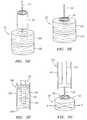
- an alternative vascular sealing device 20includes a number of disc-shaped sealing member 22a-d that are slidably attached to the end of a tether 24.
- the disc-shaped sealing members 22a-d and tether 24may be formed of any of the same materials described above in relation to the sealing device 20 shown in Figures IA and IB.
- the sealing device 20is shown loaded into a delivery device 100, the distal end of which is shown in the Figure.
- the delivery devicehas a cylindrical delivery tube 102, shown in cross-section in Figure 3A , which in turn has an opening 104 at its distal end.
- the internal space defined by the interior of the delivery tube 102is adapted to receive and retain the sealing device 20 for delivery to an incision.
- the sealing device 20is deployed through the opening 104 (by a plunger, by retraction of the delivery tube 102, or by another mechanism associated with the delivery device) and into the incision tract, adjacent to the blood vessel opening.
- the disc-shaped sealing members 22a-care spaced apart slightly on the tether 24 in order to be slanted at an angle relative to the axis defined by the tether 24 as they are loaded into and retained within the delivery device. This slanting reduces the radial profile of the disc-shaped sealing members 22a-c, allowing them to be loaded into a smaller diameter delivery tube than would be needed if the sealing members 22a-c were loaded without the slant.
- Figure 3Bshows the sealing device 20 after delivery within an incision tract and withdrawal of the delivery device 100.
- the sealing members 22a-dremain in the slanted, spaced-apart orientation that they occupied within the interior of the delivery tube 102.
- the disc-shaped sealing members 22a-dare exposed to blood flow and begin to expand.
- it is possible and desirable to align and compress the individual disc-shaped sealing members 22a-cby backing the delivery tube 102 up against the most proximally located disc 22d, and pulling on the tether 24 (see arrow "A" in Figure 3B ) to cause the individual discs 22a-d to align and compress against one another while being retained on the tether 24.
- the effectis to form a radially compressed sealing member 22a-d having an effectively larger radial dimension.
- the compressed sealing member 22a-dis thereby lodged firmly within the incision tract, seals the tract against blood flow from the blood vessel, and promotes hemostasis.
- Figures 4A and 4Bshow still another alternative sealing device 20.
- the deviceincludes a sealing member 22 formed as a tube that surrounds a portion of a tether 24.
- a first endcap 28is attached to the end of the tether 24, and a second endcap 29 is slidably attached to the tether 24 just proximally of the tubular sealing member 22.
- the tubular sealing member 22 and tether 24may be formed of any of the same materials described above in relation to the sealing device 20 shown in Figures IA and IB.
- the end caps 28 and 29are preferably in the form of solid or semi-solid discs.
- the end capsmay be formed of either a bioabsorbable material or a non-bioabsorbable material. In one design the end caps are formed of a bioabsorbable material, preferably polymeric.
- the device 20 shown in Figures 4A and 4Bmay be delivered with a delivery device 100 as shown in Figure 4A .
- the device 20may be expelled from the delivery tube 102 through the opening 104 at its distal end by a plunger 106, or, alternatively, the delivery tube 102 is withdrawn from around the sealing device 20 as the sealing device 20 is retained in place in an incision tract. In either case, the sealing device 20 and delivery device 100 are separated, leaving the sealing device in place within an incision tract.
- the sealing device 20may be compressed in a manner similar to that described above in relation to Figures 3A through 3C .
- the plunger 106, the delivery tube 102, or some other membermay be placed against the second endcap 29 to provide a back up, and the tether 24 is then drawn taught (see arrow "A") in order to drive the two endcaps 28, 29 toward one another and compress the tubular sealing member 22.
- the tether 24may be simply held taut, and the second endcap 29 is then forced down toward the first endcap 28 by the plunger 106, the delivery tube 102, or other member (see arrows "B"), compressing the tubular sealing member 22 in the process.
- the end resultis that shown in Figure 4B , with the tubular sealing member 22 compressed radially (see arrows "E") to cause the sealing device to lodge firmly in the incision tract and to provide a seal against blood flow from the blood vessel.
- the sealing device 20includes a pair of disc-shaped sealing members 22a-b that are attached to a tether 24 near its distal end.
- the disc-shaped sealing members 22a-b and tether 24may be formed of any of the same materials described above in relation to the sealing device 20 shown in Figures IA and IB.
- two disc-shaped sealing members 22a-bare shown in the Figures, more or fewer disc-shaped sealing members may be provided.
- the discsare separated by only a small amount of space, unlike the design shown in Figures 3A-B . Therefore, as shown in Figure 5B , in order to load the disc-shaped sealing members 22a-b into the delivery tube 102 of a delivery device 100 (see arrow “L” in Figure 5B ), the disc-shape'd sealing members 22a-b are compressed radially during the loading process (see arrows "C” in Figure 5B ). In many cases, one result of this radial compression is that the disc-shaped sealing members 22a-b remain in their compressed state after delivery, i.e., after exiting the delivery tube 102.
- FIG. 5CThis effect is illustrated in Figure 5C , where a plunger 106 associated with the delivery device 100 is shown deploying the sealing device 20 by applying a force (see arrows "F") on the proximal end of the plunger 106.
- the radial dimension (see arrows "d") of the sealing members 22a-b of the sealing device 20is approximately the same as the inner diameter of the delivery tube 102 (arrows "d").
- This effectmay be problematic in cases in which the disc-shaped sealing members 22a-b are formed of a material that does not expand significantly upon deployment in an incision tract, and in cases in which the tissue in which the incision tract is formed has become inelastic due to, for example, multiple sheath exchanges during any surgical procedures.
- the sealing member 22a-bwill tend to have a radial dimension (effective diameter) that may be slightly smaller than the diameter of the incision, and the tissue sunounding the incision has insufficient elasticity to adequately collapse around the sealing member 22a-b to cause it to firmly lodge in place.
- each of the pair of disc-shaped sealing members 22a-bis provided with a cylindrical void space at its center.
- the sealing members 22a-bare preferably formed from a material that demonstrates a relatively small amount of expansion when exposed to fluids in comparison to the expansion capability of the hydrogels described above.
- An example of a suitable materialis a PGA felt material.
- a separate volumetric expansion member 30is dimensioned to be inserted into the void space formed in the sealing member 22a-b.
- the sealing device 20is then loaded into a delivery device, as shown in Figure 5F .
- the delivery device 100like those described elsewhere herein, includes a delivery tube 102 and a plunger 106 adapted to expel the sealing device 20 through the opening 104 at the distal end of the delivery device 100, or to maintain the position of the sealing device 20 while the delivery tube 102 is withdrawn.
- the sealing member 22a-bincluding the volumetric expansion member 30, is exposed to blood flow from the blood vessel.
- the expansion member associated with the sealing member 22a-bexpands radially to a much greater degree, as illustrated by arrows "E" in Figure 5G . This enhances the expansion of the disc-shaped sealing members 22a-b, causing the sealing member 22a-b to more effectively seal the incision tract against further blood flow and to promote hemostasis.
- volumetric expansion member 30may be provided on the exterior of the sealing member, or it may be embedded elsewhere within the sealing member.
- the expansion membermay also take on forms other than a rolled sheet, and the sealing member may take on forms other than the disc-shaped members shown in the Figures.
- an alternative sealing device 20includes a sealing member 22 in the form of a mechanical flower.
- the sealing member 22is preferably formed of a hydrogel or any of the other materials described herein.
- the mechanical flowerincludes a number of petals 32 that project radially away from the core 34 of the flower.
- a tether 24is attached to the core 34 and is adapted to extend out of an incision upon deployment of the sealing device 20 in an incision tract.
- the shape of the mechanical floweris selected due to its capacity for expanding after deployment and exposure to blood flow.
- the mechanical flowerprior to deployment (as, for example, while loaded in a delivery device 100), the mechanical flower may be compressed such that all of the petals 34 extend in a single general direction and each is in close proximity the others.
- the mechanical floweris allowed to "bloom," i.e., to expand such that the petals 34 separate from one another, as shown, for example, in Figure 6B .
- This expansionmay be caused by a combination of release from the confines of the delivery device and the expansion attributable to the exposure of the superabsorbent sealing member 22 to blood flow in the incision tract 50.
- This expansionprovides the capability for the sealing device to lodge firmly within a tissue tract and to seal the tract against blood flow from the blood vessel 52.
- an alternative sealing device 20includes a collection of individual fibers 36 secured by a center tie 38.
- the fibers 36are preferably formed of an hydrogel or other expansive material such as those discussed herein.
- the center tie 38is also formed of one of the materials described above, but preferably a more rigid material to provide a secure attachment to the collection of fibers 36 making up the sealing member 22.
- a tether 24extends from the center tie 38 and outward from an incision tract once the sealing device 20 is deployed.
- a construction of the sealing devicethat is particularly preferred is a composite construction that includes a tether, a sealing member, and a separate restraining member.
- the sealing member 22preferably comprises a bundle or other body of a material such as a hydrogel or other of those materials discussed herein.
- the sealing member 22may be in the form of a felt, a gel, a foam, or other solid or semi-solid material.
- the sealing member 22is enclosed and retained by a restraining member 40.
- the restraining member 40comprises a porous basket, such as a knit, braided, or woven fabric that encloses and/or encapsulates the sealing member 22.
- the restraining member 40preferably is formed from a material that is porous but fairly rigid and/or that has fairly high tensile strength in order to adequately restrain the sealing member 22.
- the restraining membermay comprise a fairly loose knit, a braided structure, a tightly-woven fabric, or something in between.
- both the sealing member 22 and the restraining member 40are formed from bioabsorbable materials.
- one of the sealing member 22 and the restraining member 40is formed of a bioabsorbable material, while the other is formed from a non-bioabsorbable material.
- Suitable bioabsorbable and non-bioabsorbable materialsare those described above.
- the restraining member 40 shown in Figures 8A and 8Bincludes a mechanism for selectively compressing and radially expanding the sealing member 22 enclosed within the restraining member 40.
- the mechanismincludes a cinch line 42 that runs through a channel 44 formed on the upper periphery of the restraining member 40.
- a snare knot 46is formed on the cinch line 42 in the channel 44 and provides the ability to draw the cinch line tight in order to compress the sealing member 22 enclosed in the restraining member 40.
- the cinch line 42When the cinch line 42 is drawn tight (see arrows "T" in Figure 8B ), it changes the shape of the porous basket forming the restraining member 40 by reducing its height, causing the volume of the sealing member 22 enclosed within the restraining member 40 to expand radially, as shown in Figure 8B .
- the material making up the restraining member 40is preferably constructed in such a way to facilitate this change of shape, such as by providing a looser or more flexible braided, woven, or knit structure along the sides of the restraining member 40.
- the cinch line 42 and snare knot 46may be accessible by way of the tether 24, or by a separate line that extends from the restraining member 40.
- the sealing device 20 shown in Figures 8A and 8Bmay be deployed in a manner similar to those described elsewhere herein.
- the sealing device 20may be deployed in an incision tract by using a delivery device having a delivery tube that expels the sealing device 20 from its distal end once properly located within the incision tract.
- the sealing device 20will encounter blood flow from the vessel being sealed, thereby causing the sealing member 22 enclosed by the restraining member 40 to expand, including radial expansion.
- the usermay selectively tighten the cinch line 42 to compress the sealing member 22 to provide additional radial expansion. In this way, the sealing device 20 may be expanded to firmly lodge the device within the incision tract to prevent its migration out of the tract and to seal the tract against blood flow.
- FIG. 9A through 91an additional embodiment of a sealing device is shown, as is a method of making the sealing device.
- the sealing device shown in Figures 9 A through 91is constructed to include a tether, a sealing member, and a restraining member.
- the sealing member 22is a hydrogel foam pad, although other bioabsorbable, highly-expandable materials may be used as well.
- the sealing member 22may be formed from a non-bioabsorbable material.
- the foam padpreferably has dimensions that allow it to be compressed and rolled (as described below) to a shape and size suitable for receipt in a delivery device and for its ultimate use as a sealing device in an incision tract.
- One method of performing this compression stepis to use a compressive roller 110 to apply a compressing force to the pad, much like a rolling pin. This method is illustrated by arrow "R" in Figure 9B .
- the result of the compression stepis to obtain a highly compressed, flat foam pad of hydrogel or other bioabsorbable (or non-bioabsorbable) material.
- the sealing memberis rolled into a coil.
- the coil shapeis preferred because it creates a low-profile sealing member in the dry state that is capable of a high degree of radial expansion when the sealing member is exposed to blood flow.
- the low profile in the dry stateis useful to facilitate delivery of the sealing device, while the high degree of radial expansion when exposed to fluid is useful to facilitate firmly lodging the sealing device in an incision tract and sealing the tract against blood flow.
- Other and different shapes and dimensionsare also possible, and each may contribute more or less to these objectives.
- the sealing membermay be a wadded or otherwise compressed mass.
- the coiled sheet shapeis a preferred embodiment.
- Figure 9Dshows a preferred restraining member 40 for use with the sealing device.
- the restraining member 40is a porous, tubular member formed of a knit, woven, or braided material.
- the composition of the tubular restraining member 40is preferably of a bioabsorbable material, such as suture material formed from PGA, PLA, or PGLA.
- the restraining member 40may be formed of a non-bioabsorbable material, such as nylon or stainless steel filament mesh.
- the knit or braided structureallows the restraining member 40 to expand when needed to accommodate the sealing member 22 within its interior.
- Figure 9Eprovides an illustration of a process for inserting the sealing member 22, in this case a compressed and coiled sheet of hydrogel material, into the restraining member 40.
- the arrow "A"indicates passage of the sealing member 22 into the interior space defined by the restraining member 40, within which the sealing member is enclosed and retained.
- the woven, braided, or knit structure of the restraining member 40 materialallows for expansion of the restraining member 40 to accommodate the sealing member 22.
- the open end of the restraining member 40may beclosed or sealed to fully enclose the sealing member 22, as shown in Figure 9F .
- a proximal portion 41 of the restraining member 40 that extends proximally of the sealing member 22may be used instead of, or as a replacement for, a tether as used in other embodiments described herein.
- the proximal portion 41 of the restraining member 40would extend out of the incision tract and may be used to manipulate the sealing device 20 and/or to remove the sealing device 20 from the incision if necessary.
- Figure 9Fillustrates one embodiment of the complete sealing device 20 in its predeployment, unexpanded state.
- This statein which the sealing device 20 has a reduced profile, is suitable for loading the device 20 into an appropriate delivery device, such as the delivery devices described previously herein.
- the sealing deviceis then able to be delivered by, for example, expelling the device out of the open distal end of a delivery tube, into an incision tract and near an opening in a target blood vessel.
- the sealing member 22 within the sealing devicewill expand, as illustrated by the arrows "E" in Figure 9G . This expansion will cause the sealing device 20 to lodge firmly within the incision tract, sealing the incision against blood flow.
- Figures 9H and 91show a sealing device 20 similar to that described above in relation to Figures 9F and 9G , but also including a tether 24.
- the tether 24is preferably attached to the sealing member 22 and the restraining member 40, and may be used to manipulate the sealing device 20 after deployment, or to remove the sealing device 20 from the incision if necessary.
- the tether 24may be attached to the sealing member 22 and restraining member 40 in a manner that allows the user to exert an upward force (see arrows "F") on the tether that increases the radial expansion (arrows "E") of the sealing member 22 inside the restraining member 40.
- This increased radial expansion due to mechanical manipulation of the sealing devicewill increase the ability of the device to lodge firmly within the incision tract, seal the incision against blood flow, and promote hemostasis.
- each of the foregoing designsmay also be constructed of a combination of one or more components formed from bioabsorbable materials, and one or more components formed from non-bioabsorbable materials.
Landscapes
- Health & Medical Sciences (AREA)
- Surgery (AREA)
- Life Sciences & Earth Sciences (AREA)
- Heart & Thoracic Surgery (AREA)
- Molecular Biology (AREA)
- Veterinary Medicine (AREA)
- Engineering & Computer Science (AREA)
- Biomedical Technology (AREA)
- Public Health (AREA)
- Medical Informatics (AREA)
- Nuclear Medicine, Radiotherapy & Molecular Imaging (AREA)
- Animal Behavior & Ethology (AREA)
- General Health & Medical Sciences (AREA)
- Reproductive Health (AREA)
- Vascular Medicine (AREA)
- Cardiology (AREA)
- Surgical Instruments (AREA)
- Materials For Medical Uses (AREA)
Description
- The present invention relates generally to apparatus for sealing or closing passages through tissue, and more particularly to devices for sealing punctures or other openings communicating with body lumens, such as blood vessels.
- Catheterization and interventional procedures, such as angioplasty or stenting, generally are performed by inserting a hollow needle through a patient's skin and muscle tissue into the vascular system. A guide wire may then be passed through the needle lumen into the patient's blood vessel accessed by the needle. The needle may be removed, and an introducer sheath may be advanced over the guide wire into the vessel, e.g., in conjunction with or subsequent to a dilator. A catheter or other device may then be advanced through a lumen of the introducer sheath and over the guide wire into a position for performing a medical procedure. Thus, the introducer sheath may facilitate introduction of various devices into the vessel, while minimizing trauma to the vessel wall and/or minimizing blood loss during a procedure.
- Upon completion of the procedure, the devices and introducer sheath may be removed, leaving a puncture site in the vessel wall. External pressure may be applied to the puncture site until clotting and wound sealing occur. This procedure, however, may be time consuming and expensive, requiring as much as an hour of a physician's or nurse's time. It is also uncomfortable for the patient, and requires that the patient remain immobilized in the operating room, catheter lab, or holding area. In addition, a risk of hematoma exists from bleeding before hemostasis occurs.
- Various apparatus have been suggested for percutaneously sealing a vascular puncture by occluding the puncture site. For example,
U.S. Patent Nos. 5,192,302 and5,222,974, issued to Kensey et al. , describe the use of a biodegradable plug that may be delivered through an introducer sheath into a puncture site. When deployed, the plug may seal the vessel and provide hemostasis. Such devices, however, may be difficult to position properly with respect to the vessel, which may be particularly significant since it is generally undesirable to expose the plug material, e.g., collagen, within the bloodstream, where it may float downstream and risk causing an embolism. - In
DE19916787 there is described a tamponade for stopping blood flow and/or the antiseptic treatment of wounds, for use in hollow areas during nasal surgery. The tamponade comprises a longitudinal member made of foam, and a surrounding coating made of a closed layer material. The coating is flat on the base member. The base member is preferably a polymer, especially polyurethane. EP0084960 discloses an absorbent device comprising a restraining member comprising a woven first material and defining an interior space therein, a sealing member comprising a second material at least partially located within the interior space of said restraining member, and wherein the sealing member will expand upon exposure to blood flow.- Another technique has been suggested that involves percutaneously suturing the puncture site, such as that disclosed in
U.S. Patent No. 5,304,184, issued to Hathaway et al. Percutaneous suturing devices, however, may require significant skill by the user, and may be mechanically complex and expensive to manufacture. - Staples and surgical clips have also been suggested for closing wounds or other openings in tissue. For example,
U.S. Patent Nos. 5,007,921 and5,026,390, issued to Brown , disclose staples that may be used to close a wound or incision. In one example, an "S" shaped staple is disclosed that includes barbs that may be engaged into tissue on either side of the wound. In another example, a ring-shaped staple is disclosed that includes barbs that project from the ring. These staples, however, have a large cross-sectional profile and therefore may not be easy to deliver through a percutaneous site to close an opening in a vessel wall. - United States Patent No.
6,033,427 , issued to Lee, discloses a method and device for sealing internal puncture sites which, in one example, uses a dual lumen bleed back system in which the distal bleed back ports are axially spaced from each other such that when the obturator is in a certain location, there will be bleed back through one of the lumens, but not through the other. - In addition, skin seals have been proposed that may be threaded into an opening in skin. For example,
U.S. Patent No. 5,645,565, issued to Rudd et al. , discloses a surgical plug that may be screwed into a puncture to seal the puncture. The surgical plug includes an enlarged cap and a threaded shaft that extends from the cap. During an endoscopic procedure, the plug may be threaded into an opening through skin until the cap engages the surface of the skin. The plug is intended to seal the opening communicating with a body cavity to prevent insufflation fluid from leaking from the cavity. Such plugs, however, may only be used at the surface of the skin, and may not be introduced through tissue, for example, to seal an opening in the wall of a blood vessel or other subcutaneous region. - Various methods and means for determining the location of the distal end of a closure device have been proposed, including "bleed back" methodology such as that disclosed in United States Patent No.
4,738,658 issued to Magro et al. However, prior bleed back devices have been constructed such that blood flow out of the patient continues for a longer period of time during deployment of the sealing means than would be desirable. - A further development in bleed back technology is disclosed in published United States Patent Application
2004/0019330 , in which a control element having an enlarged distal end is used both to control blood flow through the blood vessel puncture and to provide an indication of the position of the distal end of an introducer sheath by withdrawing the enlarged distal end from the lumen of the blood vessel into the puncture in the wall of the blood vessel such that bleed back is, according to this published application, stopped. Leschinsky Patent No. 5,871,501 discloses the use of an anchor on a guide wire to provide an indication of the location of the wall of a blood vessel to assist in the placement of a hemostatic material to block flow of blood out of a puncture in the vessel.- Although these and other methods and devices have been proposed for deploying a plug to prevent blood flow from a puncture in a blood vessel, a need remains for a safe and effective device for deploying a plug for this purpose, and for plugs that are more easily deployed and that provide improved prevention of blood flow.
- The present invention is directed to improved vascular sealing devices used to seal incisions and/or punctured blood vessels. The vascular sealing devices are particularly useful for sealing incisions and punctures that result from catheterization or interventional procedures, such as angioplasty or stenting, although they are not limited to such uses. These incisions and punctures are commonly made to the femoral artery, and the devices described herein are particularly adapted for these purposes. It should be understood, however, that the devices may also be used to seal incisions and/or punctures in other blood vessels or organs.
- According to the present invention there is described a device having the features of claim 1 for substantially sealing a wound that extends through tissue to an opening in a body lumen.
- In several of the described devices, the sealing device includes a sealing member and a tether. The sealing member generally performs the function of occupying a space in an incision, puncture, or other wound and sealing the space in the incision, puncture, or wound that it occupies, to prevent further blood flow. The tether is typically attached in some manner to the sealing member, and provides the user with the ability to withdraw the sealing member if necessary. In certain devices, the tether also provides the user with the ability to manipulate the sealing member for desired effect, such as to radially expand the sealing member within the incision. The sealing device further includes a restraining member associated with the sealing member. The restraining member provides the ability to more securely restrain the sealing member to prevent it from migrating from the deployment location within a tissue tract. The restraining member may also provide an additional capability of manipulating the sealing member after deployment.
- It is desirable to have the sealing member material expand when the sealing member is deployed and exposed to blood flow from the target vessel. This expansion may cause the sealing member, and therefore the sealing device, to expand radially upon deployment and to thereby engage the incision tissue more firmly, thus tending to prevent migration of the sealing device and increase the effectiveness of the seal.
- The sealing device may take any of a variety of different forms or shapes depending upon the nature of the intended use, the material used to make up the device, and other factors.
- Preferably, the tether is attached to the sealing member and is adapted to extend proximally from the sealing member, through and out of the incision, thereby allowing for manipulation by the user. The tether may be used to adjust the sealing member after its deployment, such as by increasing the effective radial dimension of the sealing member, or to remove the sealing member altogether if necessary.
- In several preferred embodiments, the sealing device has a composite structure that includes one or more sealing members, as described above, and one or more restraining members. Preferably, the restraining member provides the ability to more easily deliver a sealing member and the ability to reduce the likelihood that the sealing member will migrate after its deployment. In a particular preferred form, the restraining member comprises a braided "sock" that encloses the sealing member and allows the sealing member to be more easily delivered to an incision tract.
- In several preferred embodiments, the sealing member, restraining member, and the tether of the vascular sealing device are preferably formed of bioabsorbable materials such as collagen, polyglycolic acids (PGAs), polylactides (PLAs), hydrogel, or gel-foam. These materials may be provided in solid, gel, foam, felt, or other forms. Of these, hydrogels, such as hydroxypropyl cellulose (HPC) hydrogels, are particularly preferred to be used to make the sealing member due to several of their physical properties. In particular, hydrogels are highly absorbent and exhibit high mechanical strength after absorbing a large amount of liquid.
- The vascular sealing devices described herein may be deployed by any suitable mechanism. One such mechanism particularly adapted for deploying such devices in an incision created by a catheterization or interventional procedure is described in co-pending published United States Patent Application
2005/0085856 , entitled "Locator and Delivery Device and Method of Use," filed on May 21, 2004, and assigned to Ensure Medical, Inc., the assignee herein. - The descriptions herein are particularly directed to sealing puncture wounds created during catheterization or interventional procedures, particularly to such wounds in the femoral artery, but it is to be understood that the vascular sealing devices of the present invention can be used to seal other blood vessels and puncture wounds in them. With that understanding, we turn to a more detailed description of the preferred embodiments.
- Figure IA is an illustration of a vascular sealing device.
- Figure IB is an illustration of the device shown in Figure IA, shown in an expanded state.
Figure 2A is an illustration of an alternative vascular sealing device.Figure 2B is an illustration of the device shown inFigure 2A , shown in an unexpanded state.Figure 2C is an illustration of the device shown inFigure 2A , shown in an expanded state.Figure 3A is an illustration of another vascular sealing device shown within a delivery tube prior to deployment.Figure 3B is an illustration of the vascular sealing device shown inFigure 3A , shown after deployment by a delivery tube.Figure 3C is an illustration of the vascular sealing device shown inFigure 3A , shown after alignment and compression of the discs contained on the device.Figure 4A is an illustration of another vascular sealing device. shown after deployment by a delivery tube.Figure 4B is an illustration of the vascular sealing device shown inFigure 4A , shown after compression of the end caps contained on the device.Figure 5A is an illustration of another vascular sealing device.Figure 5B is an illustration of a process for loading the sealing device shown inFigure 5A into a delivery tube.Figure 5C is an illustration of a the sealing device shown inFigure 5A , shown after deployment from the delivery tube.Figure 5D is an illustration of a process for making a vascular sealing device according to the present invention.Figure 5E is an illustration of a vascular sealing device that is the product of the process shown inFigure 5D .Figure 5F is an illustration of the vascular sealing device shown inFigure 5E , shown as loaded into a delivery tube.Figure 5G is an illustration of the vascular sealing device shown inFigure 5E , shown after deployment from the delivery tube.Figure 6A is an illustration of another vascular sealing device.Figure 6B is an illustration of the device shown inFigure 6A , shown in an expanded state.Figure 7A is an illustration of another vascular sealing device.Figure 7B is an illustration of the device shown inFigure 7A , shown in an expanded state.Figure 8A is an illustration of another vascular sealing device according to the present invention.Figure 8B is an illustration of the vascular sealing device shown inFigure 8A , shown in an expanded state.Figure 9A is an illustration of a pad used as a starting material for a sealing member,Figure 9B is an illustration of a process for compressing the pad shown inFigure 9B .Figure 9C is an illustration the pad shown inFigure 9A , after compression, shown partially rolled into a coiled form.Figure 9D is an illustration of a tube of braided material suitable for use as a restraining member according to the present invention.Figure 9E is an illustration of part of a process of inserting the pad shown inFigure 9 A in its coiled form into the tube shown inFigure 9D .Figure 9F is an illustration of a vascular sealing device according to the present invention.Figure 9G is an illustration of the device shown inFigure 9F , shown in an expanded state.Figure 9H is an illustration of a vascular sealing device similar to that shown inFigure 9F , further including a separate tether member.Figure 9I is an illustration of the device shown inFigure 9H , shown in an expanded state.- Figures IA and IB are rudimentary illustrations of a vascular sealing device. The
device 20 includes a sealingmember 22 retained on atether 24. The sealingmember 22 is preferably retained on thetether 24 at or near its distal end point by astop member 26 formed at the distal end of thetether 24. Thestop member 26 is preferably a knot formed at the distal end of thetether 24. Figure IA shows the device in its unexpanded, predeployment state. Figure IB shows the device after it has expanded due to fluid exposure. - The sealing
member 22 is formed from a material that is able to expand, or to be expanded, once the sealingdevice 22 is deployed for use. The sealing member is preferably formed from a bioabsorbable material, but, the sealing member may be formed from a non-bioabsorbable material. Examples of suitable bioabsorbable materials include bioabsorbable collagen, polyglycolic acids (PGAs), polylactides (PLAs), polyglycol-lactides (PGLAs), hydrogels, and gel-foams. These materials may be provided in solid, gel, foam, felt, or other forms as appropriate for the particular application. Of these materials, hydrogels are particularly preferred due to several of their physical properties. A hydrogel is an absorbent, microporous gel comprising a crosslinked polymer having interconnected fluid cells distributed throughout its mass. Hydrogels absorb fluids very quickly, and exhibit high mechanical strength even after absorbing large amounts of fluids. Moreover, hydrogels typically expand isotropically, meaning that they are able to maintain their original shapes during and after expansion due to fluid absorption. Additional information relating to hydrogels suitable for use in the vascular sealing devices described herein can be found in United States Patent Nos.5,573,994 and6,030,442 . - Examples of nonbioabsorbable materials that may be used to form the sealing
member 22 include nylon, stainless steel, ceramic materials, titanium, gold, platinum, nickel, nickel-titanium alloys, other metals and metal alloys, and other conventional materials suitable for medical use. - The sealing
member 22 of the device shown in Figure IA has a generally tubular shape that surrounds thetether 24 near its end. The sealingmember 22 may be loosely or firmly secured to thetether 24 by conventional means, or it may be allowed to slide along at least a portion of the length of thetether 24. - The
tether 24 shown in the Figure IA sealing device performs at least the function of providing the user the ability to retrieve thesealing device 20 from its deployed state if necessary. Thetether 24 is preferably formed of conventional suture material, such as a biodegradable polymer having sufficient tensile strength to perform the above functions. Examples of such materials include PGA, PLA, and PGLA polymers. Alternatively, the tether may be formed of a non-bioabsorbable material such as those described above. - The
stop member 26 shown in the Figure IA sealing device performs at least the function of retaining the sealingmember 22 on thetether 24. Thestop member 26 may be formed of any biocompatible material suitable to perform this purpose. Alternatively, as in thedevice 20 shown in Figures IA and IB, thestop member 26 may comprise a knot formed at the end of thetether 24. - The sealing
device 20 is particularly adapted to be used to seal an incision, puncture, or other wound found in the body of a patient, typically a human or other mammal. Thedevice 20 may be delivered to the wound site by any suitable means. For example, in the case of an incision created to gain access to the femoral artery for a catheterization or other interventional procedure, the device may be delivered to the incision tract using the delivery device described in co-pending published United States Patent Application2005/0085856 , entitled "Locator and Delivery Device and Method of Use," filed on May 21, 2004, and assigned to Ensure Medical, Inc., the assignee herein (hereinafter referred to as "the'856 application"). The delivery device described in the '856 application is adapted to deliver a vascular plug or other sealing device in an incision tract to a point proximal to the blood vessel. In the case of thevascular sealing device 20 shown in Figure IA herein, once deployed, the sealingmember 22 is exposed to blood flow from the blood vessel. This exposure causes the sealingmember 22 to expand due to absorption of the blood, as shown in Figure IB. This expansion of the sealingmember 22, which has been inserted into the incision tract, causes the sealingmember 22 to lodge itself firmly in the incision tract, thereby preventing the sealingdevice 20 from migrating out of position and creating an effective seal that prevents blood flow from the vessel. - The components making up the sealing
device 20 may be formed entirely of bioabsorbable materials, or they may be formed of a combination of bioabsorbable and non-bioabsorbable materials. For example, the sealingmember 22 may be formed of one or more bioabsorbable materials, while thetether 24 is formed of a nonbioabsorbable material. Other combinations are also possible. - Optionally, a clotting agent or other hemostasis promoting material - such as a thromboplastin or other conventional clotting agent- may be incorporated into, added to, or used in combination with the sealing
device 20. Figures 2A through 2C show an alternativevascular sealing device 20 in which thetether 24 is used to enclose and retain the sealingmember 22. With reference toFigure 2A , thedevice 20 includes a sealingmember 22 and atether 24. The sealingmember 22 andtether 24 may be formed of any of the same materials described above in relation to the sealingdevice 20 shown in Figures IA and IB. Thetether 24 is formed in asurgical knot 25 at its distal end in order to loosely enclose the sealingmember 22. InFigure 2B , thedevice 20 is shown with thesurgical knot 25 snugged in order to more firmly enclose and retain the sealingmember 22 prior to deployment of the device. Upon deployment into an incision tract, the sealingmember 22 comes into contact with blood flowing from a vessel and expands, providing a seal, as shown inFigure 2C .- Turning to
Figures 3A through 3C , an alternativevascular sealing device 20 includes a number of disc-shapedsealing member 22a-d that are slidably attached to the end of atether 24. Astop member 26, preferably a knot formed at the distal end of the tether, retains the sealingmembers 22a-c on thetether 24. The disc-shapedsealing members 22a-d andtether 24 may be formed of any of the same materials described above in relation to the sealingdevice 20 shown in Figures IA and IB. - Turning first to
Figure 3A , the sealingdevice 20 is shown loaded into adelivery device 100, the distal end of which is shown in the Figure. The delivery device has acylindrical delivery tube 102, shown in cross-section inFigure 3A , which in turn has anopening 104 at its distal end. The internal space defined by the interior of thedelivery tube 102 is adapted to receive and retain thesealing device 20 for delivery to an incision. Once thedelivery device 100 is placed into the incision at the appropriate location for delivery of the sealingdevice 20, *————————————————————————————————""— the sealingdevice 20 is deployed through the opening 104 (by a plunger, by retraction of thedelivery tube 102, or by another mechanism associated with the delivery device) and into the incision tract, adjacent to the blood vessel opening. - As shown in
Figure 3A , the disc-shapedsealing members 22a-c are spaced apart slightly on thetether 24 in order to be slanted at an angle relative to the axis defined by thetether 24 as they are loaded into and retained within the delivery device. This slanting reduces the radial profile of the disc-shapedsealing members 22a-c, allowing them to be loaded into a smaller diameter delivery tube than would be needed if the sealingmembers 22a-c were loaded without the slant. Figure 3B shows the sealingdevice 20 after delivery within an incision tract and withdrawal of thedelivery device 100. At this point, the sealingmembers 22a-d remain in the slanted, spaced-apart orientation that they occupied within the interior of thedelivery tube 102. Also at this point, the disc-shapedsealing members 22a-d are exposed to blood flow and begin to expand. As shown inFigure 3C , it is possible and desirable to align and compress the individual disc-shapedsealing members 22a-c by backing thedelivery tube 102 up against the most proximally locateddisc 22d, and pulling on the tether 24 (see arrow "A" inFigure 3B ) to cause theindividual discs 22a-d to align and compress against one another while being retained on thetether 24. The effect is to form a radially compressed sealingmember 22a-d having an effectively larger radial dimension. Thecompressed sealing member 22a-d is thereby lodged firmly within the incision tract, seals the tract against blood flow from the blood vessel, and promotes hemostasis.Figures 4A and 4B show still anotheralternative sealing device 20. In this design, the device includes a sealingmember 22 formed as a tube that surrounds a portion of atether 24. Afirst endcap 28 is attached to the end of thetether 24, and asecond endcap 29 is slidably attached to thetether 24 just proximally of thetubular sealing member 22. Thetubular sealing member 22 andtether 24 may be formed of any of the same materials described above in relation to the sealingdevice 20 shown in Figures IA and IB. The end caps 28 and 29 are preferably in the form of solid or semi-solid discs. The end caps may be formed of either a bioabsorbable material or a non-bioabsorbable material. In one design the end caps are formed of a bioabsorbable material, preferably polymeric.- The
device 20 shown inFigures 4A and 4B may be delivered with adelivery device 100 as shown inFigure 4A . Thedevice 20 may be expelled from thedelivery tube 102 through theopening 104 at its distal end by aplunger 106, or, alternatively, thedelivery tube 102 is withdrawn from around the sealingdevice 20 as the sealingdevice 20 is retained in place in an incision tract. In either case, the sealingdevice 20 anddelivery device 100 are separated, leaving the sealing device in place within an incision tract. - After delivery, the sealing
device 20 may be compressed in a manner similar to that described above in relation toFigures 3A through 3C . In reference toFigure 4B , theplunger 106, thedelivery tube 102, or some other member may be placed against thesecond endcap 29 to provide a back up, and thetether 24 is then drawn taught (see arrow "A") in order to drive the twoendcaps tubular sealing member 22. Alternatively, thetether 24 may be simply held taut, and thesecond endcap 29 is then forced down toward thefirst endcap 28 by theplunger 106, thedelivery tube 102, or other member (see arrows "B"), compressing thetubular sealing member 22 in the process. In either event, the end result is that shown inFigure 4B , with thetubular sealing member 22 compressed radially (see arrows "E") to cause the sealing device to lodge firmly in the incision tract and to provide a seal against blood flow from the blood vessel. - Turning next to
Figures 5A through 5G , a still further design of the sealingdevice 20 is shown. In reference toFigure 5A , the sealingdevice 20 includes a pair of disc-shapedsealing members 22a-b that are attached to atether 24 near its distal end. The disc-shapedsealing members 22a-b andtether 24 may be formed of any of the same materials described above in relation to the sealingdevice 20 shown in Figures IA and IB. Moreover, although two disc-shapedsealing members 22a-b are shown in the Figures, more or fewer disc-shaped sealing members may be provided. - As shown in the Figures, the discs are separated by only a small amount of space, unlike the design shown in
Figures 3A-B . Therefore, as shown inFigure 5B , in order to load the disc-shapedsealing members 22a-b into thedelivery tube 102 of a delivery device 100 (see arrow "L" inFigure 5B ), the disc-shape'd sealingmembers 22a-b are compressed radially during the loading process (see arrows "C" inFigure 5B ). In many cases, one result of this radial compression is that the disc-shapedsealing members 22a-b remain in their compressed state after delivery, i.e., after exiting thedelivery tube 102. This effect is illustrated inFigure 5C , where aplunger 106 associated with thedelivery device 100 is shown deploying the sealingdevice 20 by applying a force (see arrows "F") on the proximal end of theplunger 106. After deployment, the radial dimension (see arrows "d") of the sealingmembers 22a-b of the sealingdevice 20 is approximately the same as the inner diameter of the delivery tube 102 (arrows "d"). This effect may be problematic in cases in which the disc-shapedsealing members 22a-b are formed of a material that does not expand significantly upon deployment in an incision tract, and in cases in which the tissue in which the incision tract is formed has become inelastic due to, for example, multiple sheath exchanges during any surgical procedures. In those cases, the sealingmember 22a-b will tend to have a radial dimension (effective diameter) that may be slightly smaller than the diameter of the incision, and the tissue sunounding the incision has insufficient elasticity to adequately collapse around the sealingmember 22a-b to cause it to firmly lodge in place. - One solution proposed herein is to provide a volumetric expansion member in association with the sealing member. One example is shown in
Figures 5D through 5G . Turning toFigure 5D , each of the pair of disc-shapedsealing members 22a-b is provided with a cylindrical void space at its center. The sealingmembers 22a-b are preferably formed from a material that demonstrates a relatively small amount of expansion when exposed to fluids in comparison to the expansion capability of the hydrogels described above. An example of a suitable material is a PGA felt material. A separatevolumetric expansion member 30 is dimensioned to be inserted into the void space formed in the sealingmember 22a-b. As shown inFigure 5D , theexpansion member 30 may be formed as a rolled sheet of highly expandable material, such as a hydrogel foam pad, that is formed to surround thetether 24. Theexpansion element 30 may then be inserted into the void space formed in the sealingelement 22a-b, as shown, for example, inFigure 5E . - The sealing
device 20 is then loaded into a delivery device, as shown inFigure 5F . Thedelivery device 100, like those described elsewhere herein, includes adelivery tube 102 and aplunger 106 adapted to expel thesealing device 20 through theopening 104 at the distal end of thedelivery device 100, or to maintain the position of the sealingdevice 20 while thedelivery tube 102 is withdrawn. Upon deployment, the sealingmember 22a-b, including thevolumetric expansion member 30, is exposed to blood flow from the blood vessel. Whereas the disc-shapedsealing members 22a-b tend only to expand slightly upon exposure to fluids, the expansion member associated with the sealingmember 22a-b expands radially to a much greater degree, as illustrated by arrows "E" inFigure 5G . This enhances the expansion of the disc-shapedsealing members 22a-b, causing the sealingmember 22a-b to more effectively seal the incision tract against further blood flow and to promote hemostasis. - Although a particular orientation of the
volumetric expansion member 30 in relation to the sealingmember 22a-b is illustrated inFigures 5D through 5G , it should be understood that other and different orientations are also possible. For example, the volumetric expansion member may be provided on the exterior of the sealing member, or it may be embedded elsewhere within the sealing member. The expansion member may also take on forms other than a rolled sheet, and the sealing member may take on forms other than the disc-shaped members shown in the Figures. These and other variations are possible while obtaining the advantages provided by a composite structure including one or more sealing members formed from a first material, and one or more volumetric expansion members formed from a second material having substantially greater expansion capacity than the first material. The sealing members and volumetric expansion members may be formed entirely of a combination of bioabsorbable materials, or by a combination of bioabsorbable materials and non-bioabsorbable materials. - Turning next to
Figures 6A and 6B , analternative sealing device 20 includes a sealingmember 22 in the form of a mechanical flower. The sealingmember 22 is preferably formed of a hydrogel or any of the other materials described herein. The mechanical flower includes a number ofpetals 32 that project radially away from thecore 34 of the flower. Atether 24 is attached to thecore 34 and is adapted to extend out of an incision upon deployment of the sealingdevice 20 in an incision tract. - The shape of the mechanical flower is selected due to its capacity for expanding after deployment and exposure to blood flow. For example, as shown in
Figure 6A , prior to deployment (as, for example, while loaded in a delivery device 100), the mechanical flower may be compressed such that all of thepetals 34 extend in a single general direction and each is in close proximity the others. Upon deployment, however, the mechanical flower is allowed to "bloom," i.e., to expand such that thepetals 34 separate from one another, as shown, for example, inFigure 6B . This expansion may be caused by a combination of release from the confines of the delivery device and the expansion attributable to the exposure of thesuperabsorbent sealing member 22 to blood flow in theincision tract 50. This expansion provides the capability for the sealing device to lodge firmly within a tissue tract and to seal the tract against blood flow from theblood vessel 52. - Turning next to
Figure 7 , analternative sealing device 20 includes a collection ofindividual fibers 36 secured by acenter tie 38. Thefibers 36 are preferably formed of an hydrogel or other expansive material such as those discussed herein. Thecenter tie 38 is also formed of one of the materials described above, but preferably a more rigid material to provide a secure attachment to the collection offibers 36 making up the sealingmember 22. Atether 24 extends from thecenter tie 38 and outward from an incision tract once the sealingdevice 20 is deployed. - A construction of the sealing device that is particularly preferred is a composite construction that includes a tether, a sealing member, and a separate restraining member. One example of this structure is shown in the embodiment illustrated in
Figures 8A and 8B . In this embodiment, the sealingmember 22 preferably comprises a bundle or other body of a material such as a hydrogel or other of those materials discussed herein. The sealingmember 22 may be in the form of a felt, a gel, a foam, or other solid or semi-solid material. The sealingmember 22 is enclosed and retained by a restrainingmember 40. In the embodiment shown inFigures 8A and 8B , the restrainingmember 40 comprises a porous basket, such as a knit, braided, or woven fabric that encloses and/or encapsulates the sealingmember 22. The restrainingmember 40 preferably is formed from a material that is porous but fairly rigid and/or that has fairly high tensile strength in order to adequately restrain the sealingmember 22. The restraining member may comprise a fairly loose knit, a braided structure, a tightly-woven fabric, or something in between. Preferably, both the sealingmember 22 and the restrainingmember 40 are formed from bioabsorbable materials. In alternative designs, however, one of the sealingmember 22 and the restrainingmember 40 is formed of a bioabsorbable material, while the other is formed from a non-bioabsorbable material. Suitable bioabsorbable and non-bioabsorbable materials are those described above. - The restraining
member 40 shown inFigures 8A and 8B includes a mechanism for selectively compressing and radially expanding the sealingmember 22 enclosed within the restrainingmember 40. The mechanism includes acinch line 42 that runs through achannel 44 formed on the upper periphery of the restrainingmember 40. Asnare knot 46 is formed on thecinch line 42 in thechannel 44 and provides the ability to draw the cinch line tight in order to compress the sealingmember 22 enclosed in the restrainingmember 40. When thecinch line 42 is drawn tight (see arrows "T" inFigure 8B ), it changes the shape of the porous basket forming the restrainingmember 40 by reducing its height, causing the volume of the sealingmember 22 enclosed within the restrainingmember 40 to expand radially, as shown inFigure 8B . The material making up the restrainingmember 40 is preferably constructed in such a way to facilitate this change of shape, such as by providing a looser or more flexible braided, woven, or knit structure along the sides of the restrainingmember 40. Thecinch line 42 andsnare knot 46 may be accessible by way of thetether 24, or by a separate line that extends from the restrainingmember 40. - The sealing
device 20 shown inFigures 8A and 8B may be deployed in a manner similar to those described elsewhere herein. For example, the sealingdevice 20 may be deployed in an incision tract by using a delivery device having a delivery tube that expels the sealingdevice 20 from its distal end once properly located within the incision tract. Once deployed, the sealingdevice 20 will encounter blood flow from the vessel being sealed, thereby causing the sealingmember 22 enclosed by the restrainingmember 40 to expand, including radial expansion. In addition, the user may selectively tighten thecinch line 42 to compress the sealingmember 22 to provide additional radial expansion. In this way, the sealingdevice 20 may be expanded to firmly lodge the device within the incision tract to prevent its migration out of the tract and to seal the tract against blood flow. - Turning to
Figures 9A through 91 , an additional embodiment of a sealing device is shown, as is a method of making the sealing device. The sealing device shown inFigures 9 A through 91 is constructed to include a tether, a sealing member, and a restraining member. - Turning first to
Figure 9A , in the preferred embodiment the sealingmember 22 is a hydrogel foam pad, although other bioabsorbable, highly-expandable materials may be used as well. In other designs, the sealingmember 22 may be formed from a non-bioabsorbable material. The foam pad preferably has dimensions that allow it to be compressed and rolled (as described below) to a shape and size suitable for receipt in a delivery device and for its ultimate use as a sealing device in an incision tract. In order to optimize the volume and capacity of the sealingmember 22, it is preferable to compress the foam pad prior to installation in the sealing device. One method of performing this compression step is to use acompressive roller 110 to apply a compressing force to the pad, much like a rolling pin. This method is illustrated by arrow "R" inFigure 9B . The result of the compression step is to obtain a highly compressed, flat foam pad of hydrogel or other bioabsorbable (or non-bioabsorbable) material. - Turning to
Figure 9C , in the preferred embodiment, the sealing member is rolled into a coil. The coil shape is preferred because it creates a low-profile sealing member in the dry state that is capable of a high degree of radial expansion when the sealing member is exposed to blood flow. The low profile in the dry state is useful to facilitate delivery of the sealing device, while the high degree of radial expansion when exposed to fluid is useful to facilitate firmly lodging the sealing device in an incision tract and sealing the tract against blood flow. Other and different shapes and dimensions are also possible, and each may contribute more or less to these objectives. For example, the sealing member may be a wadded or otherwise compressed mass. The coiled sheet shape is a preferred embodiment. Figure 9D shows a preferred restrainingmember 40 for use with the sealing device. The restrainingmember 40 is a porous, tubular member formed of a knit, woven, or braided material. The composition of the tubular restrainingmember 40 is preferably of a bioabsorbable material, such as suture material formed from PGA, PLA, or PGLA. In alternative designs, the restrainingmember 40 may be formed of a non-bioabsorbable material, such as nylon or stainless steel filament mesh. The knit or braided structure allows the restrainingmember 40 to expand when needed to accommodate the sealingmember 22 within its interior.Figure 9E provides an illustration of a process for inserting the sealingmember 22, in this case a compressed and coiled sheet of hydrogel material, into the restrainingmember 40. The arrow "A" indicates passage of the sealingmember 22 into the interior space defined by the restrainingmember 40, within which the sealing member is enclosed and retained. As shown in the Figure, the woven, braided, or knit structure of the restrainingmember 40 material allows for expansion of the restrainingmember 40 to accommodate the sealingmember 22. After inserting the sealingmember 22 into the restrainingmember 40, the open end of the restraining member 40 (through which the sealing member has passed) may beclosed or sealed to fully enclose the sealingmember 22, as shown inFigure 9F . In addition, aproximal portion 41 of the restrainingmember 40 that extends proximally of the sealingmember 22 may be used instead of, or as a replacement for, a tether as used in other embodiments described herein. Thus, after deployment of the sealingdevice 20, theproximal portion 41 of the restrainingmember 40 would extend out of the incision tract and may be used to manipulate the sealingdevice 20 and/or to remove thesealing device 20 from the incision if necessary.Figure 9F illustrates one embodiment of thecomplete sealing device 20 in its predeployment, unexpanded state. This state, in which thesealing device 20 has a reduced profile, is suitable for loading thedevice 20 into an appropriate delivery device, such as the delivery devices described previously herein. The sealing device is then able to be delivered by, for example, expelling the device out of the open distal end of a delivery tube, into an incision tract and near an opening in a target blood vessel. Upon exposure to blood flow, the sealingmember 22 within the sealing device will expand, as illustrated by the arrows "E" inFigure 9G . This expansion will cause thesealing device 20 to lodge firmly within the incision tract, sealing the incision against blood flow.Figures 9H and 91 show asealing device 20 similar to that described above in relation toFigures 9F and 9G , but also including atether 24. Thetether 24 is preferably attached to the sealingmember 22 and the restrainingmember 40, and may be used to manipulate the sealingdevice 20 after deployment, or to remove thesealing device 20 from the incision if necessary. For example, as shown inFigure 91 , thetether 24 may be attached to the sealingmember 22 and restrainingmember 40 in a manner that allows the user to exert an upward force (see arrows "F") on the tether that increases the radial expansion (arrows "E") of the sealingmember 22 inside the restrainingmember 40. This increased radial expansion due to mechanical manipulation of the sealing device will increase the ability of the device to lodge firmly within the incision tract, seal the incision against blood flow, and promote hemostasis.- As noted above, the several designs of the sealing device described herein are preferably constructed of components formed entirely from bioabsorbable materials. However, each of the foregoing designs may also be constructed of a combination of one or more components formed from bioabsorbable materials, and one or more components formed from non-bioabsorbable materials.
- While the invention is susceptible to various modifications, and alternative forms, specific examples thereof have been shown in the drawings and are herein described in detail. It should be understood, however, that the invention is not to be limited to the particular forms disclosed, but to the contrary, the invention is to cover all modifications and alternatives falling within the scope of the appended claims.
Claims (7)
- A device for substantially sealing a wound that extends through tissue to an opening in a body lumen comprising:a restraining member (40) comprising a knit, woven or braided first bioabsorbable material and defining an interior space therein;a sealing member (22) comprising a highly expandable second bioabsorbable material at least partially located within the interior space of said restraining member (40); anda delivery tube, wherein the restraining member (40) and the sealing member (22) are releasable in an unexpanded state from an open distal end of the delivery tube and wherein the sealing member (22) will expand upon exposure to blood flow.
- The device of claim 1 further comprising a tether (24) attached at a first end to said sealing member (22).
- The device of claim 1, wherein said first bioabsorbable material is the same as said second bioabsorbable material.
- The device of claim 1, wherein said first bioabsorbable material is selected from the group consisting of polyglycolic acid, polylactide, polyglycol-lactide acid, collagen, and hydrogel.
- The device of claim 1, wherein said restraining member (40) comprises a porous member.
- The device of claim 5, wherein said restraining member (40) is a tubular fabric member and said sealing member (22) is a coiled foam pad enclosed by said tubular fabric member.
- The device of claim 6, wherein said coiled form pad comprises a hydrogel.
Applications Claiming Priority (2)
| Application Number | Priority Date | Filing Date | Title |
|---|---|---|---|
| US11/038,995US8083768B2 (en) | 2000-12-14 | 2005-01-19 | Vascular plug having composite construction |
| PCT/US2006/001373WO2006078578A2 (en) | 2005-01-19 | 2006-01-13 | Vascular plug having composite construction |
Publications (3)
| Publication Number | Publication Date |
|---|---|
| EP1841366A2 EP1841366A2 (en) | 2007-10-10 |
| EP1841366A4 EP1841366A4 (en) | 2013-08-28 |
| EP1841366B1true EP1841366B1 (en) | 2015-08-19 |
Family
ID=36692761
Family Applications (1)
| Application Number | Title | Priority Date | Filing Date |
|---|---|---|---|
| EP06718448.1ACeasedEP1841366B1 (en) | 2005-01-19 | 2006-01-13 | Vascular plug having composite construction |
Country Status (8)
| Country | Link |
|---|---|
| US (2) | US8083768B2 (en) |
| EP (1) | EP1841366B1 (en) |
| JP (1) | JP5156390B2 (en) |
| CN (2) | CN101155567A (en) |
| AU (1) | AU2006206655B2 (en) |
| CA (1) | CA2593665C (en) |
| MX (1) | MX2007008531A (en) |
| WO (1) | WO2006078578A2 (en) |
Families Citing this family (190)
| Publication number | Priority date | Publication date | Assignee | Title |
|---|---|---|---|---|
| US7842048B2 (en) | 2006-08-18 | 2010-11-30 | Abbott Laboratories | Articulating suture device and method |
| US7001400B1 (en) | 1999-03-04 | 2006-02-21 | Abbott Laboratories | Articulating suturing device and method |
| US6964668B2 (en) | 1999-03-04 | 2005-11-15 | Abbott Laboratories | Articulating suturing device and method |
| US20040092964A1 (en) | 1999-03-04 | 2004-05-13 | Modesitt D. Bruce | Articulating suturing device and method |
| US7235087B2 (en) | 1999-03-04 | 2007-06-26 | Abbott Park | Articulating suturing device and method |
| US8137364B2 (en) | 2003-09-11 | 2012-03-20 | Abbott Laboratories | Articulating suturing device and method |
| US6461364B1 (en) | 2000-01-05 | 2002-10-08 | Integrated Vascular Systems, Inc. | Vascular sheath with bioabsorbable puncture site closure apparatus and methods of use |
| US9579091B2 (en) | 2000-01-05 | 2017-02-28 | Integrated Vascular Systems, Inc. | Closure system and methods of use |
| US6391048B1 (en) | 2000-01-05 | 2002-05-21 | Integrated Vascular Systems, Inc. | Integrated vascular device with puncture site closure component and sealant and methods of use |
| US7842068B2 (en) | 2000-12-07 | 2010-11-30 | Integrated Vascular Systems, Inc. | Apparatus and methods for providing tactile feedback while delivering a closure device |
| US8758400B2 (en) | 2000-01-05 | 2014-06-24 | Integrated Vascular Systems, Inc. | Closure system and methods of use |
| DE60144328D1 (en) | 2000-09-08 | 2011-05-12 | Abbott Vascular Inc | Surgical clamp |
| US6626918B1 (en) | 2000-10-06 | 2003-09-30 | Medical Technology Group | Apparatus and methods for positioning a vascular sheath |
| US7905900B2 (en) | 2003-01-30 | 2011-03-15 | Integrated Vascular Systems, Inc. | Clip applier and methods of use |
| US7806904B2 (en) | 2000-12-07 | 2010-10-05 | Integrated Vascular Systems, Inc. | Closure device |
| US7211101B2 (en) | 2000-12-07 | 2007-05-01 | Abbott Vascular Devices | Methods for manufacturing a clip and clip |
| US8690910B2 (en) | 2000-12-07 | 2014-04-08 | Integrated Vascular Systems, Inc. | Closure device and methods for making and using them |
| US6695867B2 (en) | 2002-02-21 | 2004-02-24 | Integrated Vascular Systems, Inc. | Plunger apparatus and methods for delivering a closure device |
| US6623510B2 (en) | 2000-12-07 | 2003-09-23 | Integrated Vascular Systems, Inc. | Closure device and methods for making and using them |
| US6846319B2 (en) | 2000-12-14 | 2005-01-25 | Core Medical, Inc. | Devices for sealing openings through tissue and apparatus and methods for delivering them |
| US8083768B2 (en) | 2000-12-14 | 2011-12-27 | Ensure Medical, Inc. | Vascular plug having composite construction |
| US6890343B2 (en) | 2000-12-14 | 2005-05-10 | Ensure Medical, Inc. | Plug with detachable guidewire element and methods for use |
| US6623509B2 (en) | 2000-12-14 | 2003-09-23 | Core Medical, Inc. | Apparatus and methods for sealing vascular punctures |
| US6896692B2 (en) | 2000-12-14 | 2005-05-24 | Ensure Medical, Inc. | Plug with collet and apparatus and method for delivering such plugs |
| US8992567B1 (en) | 2001-04-24 | 2015-03-31 | Cardiovascular Technologies Inc. | Compressible, deformable, or deflectable tissue closure devices and method of manufacture |
| US8961541B2 (en) | 2007-12-03 | 2015-02-24 | Cardio Vascular Technologies Inc. | Vascular closure devices, systems, and methods of use |
| US20080109030A1 (en) | 2001-04-24 | 2008-05-08 | Houser Russell A | Arteriotomy closure devices and techniques |
| IES20010547A2 (en) | 2001-06-07 | 2002-12-11 | Christy Cummins | Surgical Staple |
| IES20030424A2 (en) | 2002-06-04 | 2003-12-10 | Robert Stevenson | Blood vessel closure clip and delivery device |
| US7160309B2 (en) | 2002-12-31 | 2007-01-09 | Laveille Kao Voss | Systems for anchoring a medical device in a body lumen |
| US7857828B2 (en) | 2003-01-30 | 2010-12-28 | Integrated Vascular Systems, Inc. | Clip applier and methods of use |
| US8398656B2 (en) | 2003-01-30 | 2013-03-19 | Integrated Vascular Systems, Inc. | Clip applier and methods of use |
| US8821534B2 (en) | 2010-12-06 | 2014-09-02 | Integrated Vascular Systems, Inc. | Clip applier having improved hemostasis and methods of use |
| US8758398B2 (en) | 2006-09-08 | 2014-06-24 | Integrated Vascular Systems, Inc. | Apparatus and method for delivering a closure element |
| US8202293B2 (en) | 2003-01-30 | 2012-06-19 | Integrated Vascular Systems, Inc. | Clip applier and methods of use |
| US8905937B2 (en) | 2009-02-26 | 2014-12-09 | Integrated Vascular Systems, Inc. | Methods and apparatus for locating a surface of a body lumen |
| US7462188B2 (en) | 2003-09-26 | 2008-12-09 | Abbott Laboratories | Device and method for suturing intracardiac defects |
| US7361183B2 (en) | 2003-10-17 | 2008-04-22 | Ensure Medical, Inc. | Locator and delivery device and method of use |
| US8852229B2 (en) | 2003-10-17 | 2014-10-07 | Cordis Corporation | Locator and closure device and method of use |
| US7449024B2 (en) | 2003-12-23 | 2008-11-11 | Abbott Laboratories | Suturing device with split arm and method of suturing tissue |
| IES20040368A2 (en) | 2004-05-25 | 2005-11-30 | James E Coleman | Surgical stapler |
| CN102525591B (en) | 2005-01-25 | 2014-12-10 | 泰科医疗集团有限合伙公司 | Structures for permanent occlusion of a hollow anatomical structure |
| CA2833585C (en) | 2005-04-29 | 2017-06-20 | Cook Biotech Incorporated | Volumetric grafts for treatment of fistulae and related methods and systems |
| US8926654B2 (en) | 2005-05-04 | 2015-01-06 | Cordis Corporation | Locator and closure device and method of use |
| RU2404821C2 (en)* | 2005-05-04 | 2010-11-27 | Синтез ГмбХ | Connecting element |
| US8088144B2 (en) | 2005-05-04 | 2012-01-03 | Ensure Medical, Inc. | Locator and closure device and method of use |
| US8926633B2 (en) | 2005-06-24 | 2015-01-06 | Abbott Laboratories | Apparatus and method for delivering a closure element |
| US8313497B2 (en) | 2005-07-01 | 2012-11-20 | Abbott Laboratories | Clip applier and methods of use |
| US8267947B2 (en) | 2005-08-08 | 2012-09-18 | Abbott Laboratories | Vascular suturing device |
| US7883517B2 (en) | 2005-08-08 | 2011-02-08 | Abbott Laboratories | Vascular suturing device |
| US8083754B2 (en) | 2005-08-08 | 2011-12-27 | Abbott Laboratories | Vascular suturing device with needle capture |
| US9456811B2 (en) | 2005-08-24 | 2016-10-04 | Abbott Vascular Inc. | Vascular closure methods and apparatuses |
| US8758397B2 (en) | 2005-08-24 | 2014-06-24 | Abbott Vascular Inc. | Vascular closure methods and apparatuses |
| US20070060895A1 (en)* | 2005-08-24 | 2007-03-15 | Sibbitt Wilmer L Jr | Vascular closure methods and apparatuses |
| US8920442B2 (en) | 2005-08-24 | 2014-12-30 | Abbott Vascular Inc. | Vascular opening edge eversion methods and apparatuses |
| US9017361B2 (en) | 2006-04-20 | 2015-04-28 | Covidien Lp | Occlusive implant and methods for hollow anatomical structure |
| US8808310B2 (en) | 2006-04-20 | 2014-08-19 | Integrated Vascular Systems, Inc. | Resettable clip applier and reset tools |
| US7850710B2 (en)* | 2006-05-23 | 2010-12-14 | St. Jude Medical Puerto Rico Llc | Puncture closure apparatuses, sealing plugs, and related methods |
| CA2662901A1 (en)* | 2006-06-21 | 2007-12-27 | Cook Incorporated | Fistula grafts and related methods and systems useful for treating gastrointestinal fistulae |
| US8556930B2 (en) | 2006-06-28 | 2013-10-15 | Abbott Laboratories | Vessel closure device |
| US8870916B2 (en)* | 2006-07-07 | 2014-10-28 | USGI Medical, Inc | Low profile tissue anchors, tissue anchor systems, and methods for their delivery and use |
| WO2008010738A2 (en)* | 2007-01-24 | 2008-01-24 | Uros Babic | Patent foramen ovale occluder with suture based anchor |
| JP2010517641A (en)* | 2007-02-05 | 2010-05-27 | ボストン サイエンティフィック サイムド,インコーポレイテッド | Device and method for closing a vascular opening using a permanent implant |
| WO2008124361A2 (en) | 2007-04-06 | 2008-10-16 | Cook Biotech Incorporated | Fistula plugs having increased column strength and fistula plug delivery apparatuses and methods |
| US8226681B2 (en) | 2007-06-25 | 2012-07-24 | Abbott Laboratories | Methods, devices, and apparatus for managing access through tissue |
| US8574244B2 (en) | 2007-06-25 | 2013-11-05 | Abbott Laboratories | System for closing a puncture in a vessel wall |
| US8876861B2 (en) | 2007-09-12 | 2014-11-04 | Transluminal Technologies, Inc. | Closure device, deployment apparatus, and method of deploying a closure device |
| JP5426553B2 (en) | 2007-09-12 | 2014-02-26 | トランスルミナル テクノロジーズ リミテッド ライアビリティー カンパニー | Closure device, placement device, and method of placing a closure device |
| US9456816B2 (en) | 2007-09-12 | 2016-10-04 | Transluminal Technologies, Llc | Closure device, deployment apparatus, and method of deploying a closure device |
| US7875054B2 (en) | 2007-10-01 | 2011-01-25 | Boston Scientific Scimed, Inc. | Connective tissue closure device and method |
| AU2008318560B2 (en) | 2007-10-31 | 2014-12-04 | Cardinal Health 529, Llc | Method of making a vascular closure device |
| EP2209426A4 (en)* | 2007-11-02 | 2015-04-22 | Incept Llc | Apparatus and methods for sealing a vascular puncture |
| GB2467500A (en)* | 2007-11-30 | 2010-08-04 | Cook Biotech Inc | Expandable plugs and related delivery apparatuses and methods |
| US8893947B2 (en) | 2007-12-17 | 2014-11-25 | Abbott Laboratories | Clip applier and methods of use |
| US20090157101A1 (en) | 2007-12-17 | 2009-06-18 | Abbott Laboratories | Tissue closure system and methods of use |
| US7841502B2 (en) | 2007-12-18 | 2010-11-30 | Abbott Laboratories | Modular clip applier |
| CA2820166C (en)* | 2008-03-14 | 2016-05-24 | Cordis Corporation | Vascular closure device |
| US9282965B2 (en) | 2008-05-16 | 2016-03-15 | Abbott Laboratories | Apparatus and methods for engaging tissue |
| US9943302B2 (en)* | 2008-08-12 | 2018-04-17 | Covidien Lp | Medical device for wound closure and method of use |
| US9271706B2 (en)* | 2008-08-12 | 2016-03-01 | Covidien Lp | Medical device for wound closure and method of use |
| EP2330985A4 (en) | 2008-09-04 | 2015-11-18 | Curaseal Inc | Inflatable devices for enteric fistula treatment |
| US8398676B2 (en) | 2008-10-30 | 2013-03-19 | Abbott Vascular Inc. | Closure device |
| US8323312B2 (en) | 2008-12-22 | 2012-12-04 | Abbott Laboratories | Closure device |
| US8858594B2 (en) | 2008-12-22 | 2014-10-14 | Abbott Laboratories | Curved closure device |
| US20110218568A1 (en)* | 2009-01-09 | 2011-09-08 | Voss Laveille K | Vessel closure devices, systems, and methods |
| US9089311B2 (en) | 2009-01-09 | 2015-07-28 | Abbott Vascular Inc. | Vessel closure devices and methods |
| US9173644B2 (en) | 2009-01-09 | 2015-11-03 | Abbott Vascular Inc. | Closure devices, systems, and methods |
| US9486191B2 (en) | 2009-01-09 | 2016-11-08 | Abbott Vascular, Inc. | Closure devices |
| US20100179589A1 (en) | 2009-01-09 | 2010-07-15 | Abbott Vascular Inc. | Rapidly eroding anchor |
| US9414820B2 (en) | 2009-01-09 | 2016-08-16 | Abbott Vascular Inc. | Closure devices, systems, and methods |
| US20100185234A1 (en) | 2009-01-16 | 2010-07-22 | Abbott Vascular Inc. | Closure devices, systems, and methods |
| US8052914B2 (en) | 2009-02-20 | 2011-11-08 | Boston Scientific Scimed, Inc. | Modified plug for arteriotomy closure |
| US9913634B2 (en) | 2009-02-20 | 2018-03-13 | Boston Scientific Scimed, Inc. | Locking element for vascular closure device |
| US8375553B2 (en) | 2009-02-20 | 2013-02-19 | Boston Scientific Scimed, Inc. | Locking element for vascular closure device |
| US8292918B2 (en) | 2009-02-20 | 2012-10-23 | Boston Scientific Scimed, Inc. | Composite plug for arteriotomy closure and method of use |
| US8529598B2 (en) | 2009-02-20 | 2013-09-10 | Boston Scientific Scimed, Inc. | Tissue puncture closure device |
| US8317824B2 (en) | 2009-02-20 | 2012-11-27 | Boston Scientific Scimed, Inc. | Tissue puncture closure device |
| EP2416711A4 (en) | 2009-04-09 | 2017-06-07 | Cardiovascular Technologies, Inc. | Tissue closure devices, device and systems for delivery, kits and methods therefor |
| US8814903B2 (en) | 2009-07-24 | 2014-08-26 | Depuy Mitek, Llc | Methods and devices for repairing meniscal tissue |
| US8828053B2 (en)* | 2009-07-24 | 2014-09-09 | Depuy Mitek, Llc | Methods and devices for repairing and anchoring damaged tissue |
| US20110054492A1 (en) | 2009-08-26 | 2011-03-03 | Abbott Laboratories | Medical device for repairing a fistula |
| US9833225B2 (en)* | 2009-10-08 | 2017-12-05 | Covidien Lp | Wound closure device |
| US20110087274A1 (en)* | 2009-10-08 | 2011-04-14 | Tyco Healtcare Group LP, New Haven, Ct | Wound Closure Device |
| US8617206B2 (en)* | 2009-10-08 | 2013-12-31 | Covidien Lp | Wound closure device |
| US20110087273A1 (en)* | 2009-10-08 | 2011-04-14 | Tyco Healthcare Group Lp | Wound Closure Device |
| US8845682B2 (en)* | 2009-10-13 | 2014-09-30 | E-Pacing, Inc. | Vasculature closure devices and methods |
| US8858592B2 (en) | 2009-11-24 | 2014-10-14 | Covidien Lp | Wound plugs |
| US20110190870A1 (en)* | 2009-12-30 | 2011-08-04 | Boston Scientific Scimed, Inc. | Covered Stent for Vascular Closure |
| EP2533698B1 (en) | 2010-02-11 | 2018-03-28 | Boston Scientific Scimed, Inc. | Automatic vascular closure deployment devices |
| US8303624B2 (en) | 2010-03-15 | 2012-11-06 | Abbott Cardiovascular Systems, Inc. | Bioabsorbable plug |
| CA2797607A1 (en) | 2010-04-27 | 2011-11-03 | Synthes Usa, Llc | Anchor assembly including expandable anchor |
| US9743919B2 (en) | 2010-04-27 | 2017-08-29 | DePuy Synthes Products, Inc. | Stitch lock for attaching two or more structures |
| US9451938B2 (en) | 2010-04-27 | 2016-09-27 | DePuy Synthes Products, Inc. | Insertion instrument for anchor assembly |
| US9597064B2 (en) | 2010-04-27 | 2017-03-21 | DePuy Synthes Products, Inc. | Methods for approximating a tissue defect using an anchor assembly |
| JP5728779B2 (en)* | 2010-07-23 | 2015-06-03 | 国立大学法人大阪大学 | Intravascular hemostasis catheter |
| US8758399B2 (en) | 2010-08-02 | 2014-06-24 | Abbott Cardiovascular Systems, Inc. | Expandable bioabsorbable plug apparatus and method |
| BR112013001699A2 (en)* | 2010-08-03 | 2016-05-24 | Gore Enterprise Holdings Inc | fabric cap |
| US8603116B2 (en) | 2010-08-04 | 2013-12-10 | Abbott Cardiovascular Systems, Inc. | Closure device with long tines |
| US9370353B2 (en) | 2010-09-01 | 2016-06-21 | Abbott Cardiovascular Systems, Inc. | Suturing devices and methods |
| US8663252B2 (en) | 2010-09-01 | 2014-03-04 | Abbott Cardiovascular Systems, Inc. | Suturing devices and methods |
| FR2965168A1 (en)* | 2010-09-23 | 2012-03-30 | Tornier Inc | SUTURE IMPLANT COMPONENT AND SUTURE IMPLANT DEVICE COMPRISING SUCH COMPONENT |
| US8597340B2 (en) | 2010-09-17 | 2013-12-03 | Boston Scientific Scimed, Inc. | Torque mechanism actuated bioabsorbable vascular closure device |
| AU2011314156A1 (en) | 2010-09-28 | 2013-05-02 | Cook Biotech Incorporated | Devices and methods for treating fistulae and other bodily openings and passageways |
| AU2011326525B2 (en) | 2010-11-09 | 2015-06-18 | Transluminal Technologies, Llc | Specially designed magnesium-aluminum alloys and medical uses thereof in a hemodynamic environment |
| US8758402B2 (en) | 2010-12-17 | 2014-06-24 | Boston Scientific Scimed, Inc. | Tissue puncture closure device |
| US9149276B2 (en) | 2011-03-21 | 2015-10-06 | Abbott Cardiovascular Systems, Inc. | Clip and deployment apparatus for tissue closure |
| US8556932B2 (en)* | 2011-05-19 | 2013-10-15 | Abbott Cardiovascular Systems, Inc. | Collapsible plug for tissue closure |
| WO2012158740A1 (en)* | 2011-05-19 | 2012-11-22 | St. Jude Medical Puerto Rico Llc | Vascular closure device with a plug having a variable expansion rate and method for using the same |
| US9414822B2 (en) | 2011-05-19 | 2016-08-16 | Abbott Cardiovascular Systems, Inc. | Tissue eversion apparatus and tissue closure device and methods for use thereof |
| EP2717781B1 (en) | 2011-06-07 | 2019-02-06 | St. Jude Medical Puerto Rico LLC | Large bore closure device |
| JP6122424B2 (en)* | 2011-06-16 | 2017-04-26 | キュラシール インコーポレイテッド | Device for fistula treatment and related method |
| CN107137114A (en) | 2011-06-17 | 2017-09-08 | 库拉希尔公司 | The device and method treated for fistula |
| EP2747667B1 (en) | 2011-11-16 | 2016-03-09 | St. Jude Medical Puerto Rico LLC | Vascular closure system |
| WO2013074490A1 (en) | 2011-11-16 | 2013-05-23 | St. Jude Medical Puerto Rico Llc | Large bore vascular closure device with inner and outer seals |
| WO2013081905A1 (en)* | 2011-11-28 | 2013-06-06 | St. Jude Medical Puerto Rico Llc | Anchor device for large bore vascular closure |
| US9332976B2 (en) | 2011-11-30 | 2016-05-10 | Abbott Cardiovascular Systems, Inc. | Tissue closure device |
| CN111658037A (en) | 2012-03-01 | 2020-09-15 | 新特斯有限责任公司 | Surgical suture with soft core |
| US9358077B2 (en) | 2012-03-14 | 2016-06-07 | St. Jude Medical Puerto Rico Llc | Markers for tissue tract depth indication and methods |
| US8864778B2 (en) | 2012-04-10 | 2014-10-21 | Abbott Cardiovascular Systems, Inc. | Apparatus and method for suturing body lumens |
| US8858573B2 (en) | 2012-04-10 | 2014-10-14 | Abbott Cardiovascular Systems, Inc. | Apparatus and method for suturing body lumens |
| US20150182213A1 (en)* | 2012-05-24 | 2015-07-02 | Suspension Orthopaedic Solutions, Llc | Collapsible Suture Anchor |
| US9241707B2 (en) | 2012-05-31 | 2016-01-26 | Abbott Cardiovascular Systems, Inc. | Systems, methods, and devices for closing holes in body lumens |
| US9381326B2 (en)* | 2012-06-15 | 2016-07-05 | W. L. Gore & Associates, Inc. | Vascular occlusion and drug delivery devices, systems, and methods |
| WO2014021937A1 (en) | 2012-08-03 | 2014-02-06 | St. Jude Medical Puerto Rico Llc | Large bore introducer with improved seal |
| WO2014031147A1 (en) | 2012-08-24 | 2014-02-27 | St. Jude Medical Puerto Rico Llc | Balloon bailout and bioadhesive delivery device for suture based closure and methods |
| US9364209B2 (en) | 2012-12-21 | 2016-06-14 | Abbott Cardiovascular Systems, Inc. | Articulating suturing device |
| US9700297B2 (en)* | 2013-02-22 | 2017-07-11 | Arthrex, Inc. | Laminated surgical device |
| US10136885B2 (en) | 2013-03-11 | 2018-11-27 | St. Jude Medical Puerto Rico Llc | Three suture large bore closure device and methods |
| US9107646B2 (en)* | 2013-03-11 | 2015-08-18 | St. Jude Medical Puerto Rico Llc | Active securement detachable sealing tip for extra-vascular closure device and methods |
| US9055933B2 (en) | 2013-03-12 | 2015-06-16 | St. Jude Medical Puerto Rico Llc | Large bore closure secondary hemostasis bioadhesive delivery systems and methods |
| JP6423851B2 (en)* | 2013-03-13 | 2018-11-14 | アーロン・ヴィ・カプラン | Device for emptying the left atrial appendage |
| US10617425B2 (en) | 2014-03-10 | 2020-04-14 | Conformal Medical, Inc. | Devices and methods for excluding the left atrial appendage |
| US11399842B2 (en) | 2013-03-13 | 2022-08-02 | Conformal Medical, Inc. | Devices and methods for excluding the left atrial appendage |
| EP2967328A1 (en)* | 2013-03-15 | 2016-01-20 | Microtech Medical Technologies Ltd. | Implantable anchor |
| GB2513336A (en)* | 2013-04-23 | 2014-10-29 | 52 Vbl Ltd | Device and method for reducing blood flow from a bullet wound |
| EP3021762B1 (en) | 2013-07-15 | 2020-03-04 | E-Pacing, Inc. | Vasculature closure devices |
| US9282970B2 (en)* | 2013-09-30 | 2016-03-15 | Covidien Lp | Systems and methods for positioning and compacting a bodily implant |
| US10045786B2 (en) | 2013-12-20 | 2018-08-14 | Microvention, Inc. | Expansile member |
| WO2016014244A1 (en)* | 2014-07-20 | 2016-01-28 | Riina Howard Anthony | Anchored suture line, device and method for surgical suturing |
| US9795366B2 (en) | 2014-09-18 | 2017-10-24 | Edwards Lifesciences Corporation | Bio-absorbable wound closure device and method |
| MA40946A (en) | 2014-11-14 | 2017-09-19 | Access Closure Inc | APPARATUS AND METHODS FOR MAKING A VASCULAR PUNCTURE WATERTIGHT |
| EP4147649A1 (en) | 2015-02-10 | 2023-03-15 | Teleflex Life Sciences Limited | Closure device for sealing percutaneous opening in a vessel |
| WO2016141174A1 (en)* | 2015-03-04 | 2016-09-09 | TransCaval Solutions, Inc. | Multi-vessel closure system and methods of closing vessels |
| EP4299019A3 (en) | 2015-04-01 | 2024-03-06 | Boston Scientific Scimed, Inc. | Systems for delivery of gel embolics |
| US11478251B2 (en)* | 2015-10-28 | 2022-10-25 | Jayandiran Pillai | Aneurysm occluder |
| USD843573S1 (en) | 2015-11-13 | 2019-03-19 | Access Closure, Inc. | Vascular closure apparatus |
| USD865166S1 (en) | 2015-11-13 | 2019-10-29 | Access Closure, Inc. | Sheath adapter |
| USD847988S1 (en) | 2015-11-13 | 2019-05-07 | Access Closure, Inc. | Handle grip |
| EP3463109A4 (en) | 2016-05-26 | 2020-01-08 | Nanostructures, Inc. | System and methods for embolized occlusion of neurovascular aneurysms |
| WO2018031539A1 (en)* | 2016-08-12 | 2018-02-15 | Essential Medical, Inc. | Vascular closure device with locking assembly for a tamper |
| WO2018081466A2 (en) | 2016-10-27 | 2018-05-03 | Conformal Medical, Inc. | Devices and methods for excluding the left atrial appendage |
| US11426172B2 (en) | 2016-10-27 | 2022-08-30 | Conformal Medical, Inc. | Devices and methods for excluding the left atrial appendage |
| US10426449B2 (en) | 2017-02-16 | 2019-10-01 | Abbott Cardiovascular Systems, Inc. | Articulating suturing device with improved actuation and alignment mechanisms |
| US11179145B2 (en) | 2017-11-16 | 2021-11-23 | M-V Arterica AB | Collapsible tube for hemostasis |
| US20190142403A1 (en) | 2017-11-16 | 2019-05-16 | M-V Arterica AB | Tissue closure device |
| CN111936063B (en)* | 2018-01-31 | 2024-08-20 | 纳米结构公司 | Vascular occlusion device utilizing thin film nitinol foil |
| US20210270801A1 (en)* | 2018-07-03 | 2021-09-02 | Curi Bio, Inc. | Topographically guided cell migration devices and methods |
| CN109009300B (en)* | 2018-07-06 | 2020-08-14 | 华中科技大学同济医学院附属协和医院 | Femoral artery puncture point plugging hemostat |
| EP3870076A4 (en)* | 2018-10-24 | 2022-08-10 | Arterica Inc. | SELF-EXPANDING HEMOSTATIC DEVICES AND METHODS FOR FASCIAL AND VASCULAR PASSAGES |
| US12268394B2 (en) | 2019-02-08 | 2025-04-08 | Conformal Medical, Inc. | Devices and methods for excluding the left atrial appendage |
| US12144508B2 (en) | 2019-02-08 | 2024-11-19 | Conformal Medical, Inc. | Devices and methods for excluding the left atrial appendage |
| IL268572A (en) | 2019-08-07 | 2019-09-26 | Omrix Biopharmaceuticals Ltd | Expandable hemostat composed of oxidized cellulose |
| EP4044957B1 (en)* | 2019-10-15 | 2025-03-05 | Gentex Corporation | Flat panel light module with dynamic beam |
| EP4061244A4 (en) | 2019-11-19 | 2024-06-19 | Arterica Inc. | VASCULAR CLOSURE DEVICES AND METHODS |
| IL273876B2 (en)* | 2020-04-07 | 2024-02-01 | Reddress Ltd | Method and system for forming a blood clot-based wound dressing, and a coupling device enabling it |
| WO2021211213A1 (en)* | 2020-04-14 | 2021-10-21 | Deinde Medical Corp. | Closure devices and methods for sealing biologic tissue membranes |
| US20220015748A1 (en)* | 2020-07-17 | 2022-01-20 | Nextern Innovation, Llc | Systems and methods for minimally invasive delivery and in vivo creation of biomaterial structures |
| US12383246B2 (en) | 2020-10-12 | 2025-08-12 | Abbott Cardiovascular Systems, Inc. | Vessel closure device with improved safety and tract hemostasis |
| US20240148933A1 (en) | 2022-11-08 | 2024-05-09 | Ethicon, Inc. | Expandable hemostatic tablets comprising oxidized regenerated cellulose |
| CN115517725B (en)* | 2022-11-25 | 2023-03-21 | 苏州美创医疗科技有限公司 | Vascular wound sealing device and method |
Family Cites Families (283)
| Publication number | Priority date | Publication date | Assignee | Title |
|---|---|---|---|---|
| US287046A (en) | 1883-10-23 | Combined cork and screw nozzle | ||
| US2696887A (en) | 1948-02-17 | 1954-12-14 | United Aircraft Corp | Governor control for helicopters |
| US3015403A (en)* | 1959-04-08 | 1962-01-02 | American Thermos Products Comp | Threaded stopper expanding pouring lip combination for vacuum bottle |
| US3683655A (en) | 1970-03-27 | 1972-08-15 | Arlton H White | Breathing assist apparatus |
| US3678158A (en) | 1971-05-11 | 1972-07-18 | Worthington Bio Chem Corp | Treatment of herniated intervertebral discs of mammals |
| BE789781A (en) | 1971-09-24 | 1973-02-01 | Sherwood Medical Ind Inc | Suction drainage device |
| ES199828Y (en)* | 1974-01-25 | 1975-12-16 | Manufacturas De Acero | DEVICE FOR ANCHORING BRAIDS AND CORDS OF CONSTRUCTION WEAPONS. |
| NL7403762A (en)* | 1974-03-20 | 1975-09-23 | Leer Koninklijke Emballage | STOP OF PLASTIC OR SIMILAR MATERIAL, WITH EXTERNAL THREADS. |
| US3875595A (en)* | 1974-04-15 | 1975-04-08 | Edward C Froning | Intervertebral disc prosthesis and instruments for locating same |
| US3941127A (en)* | 1974-10-03 | 1976-03-02 | Froning Edward C | Apparatus and method for stereotaxic lateral extradural disc puncture |
| US3964480A (en) | 1974-10-03 | 1976-06-22 | Froning Edward C | Apparatus for sterotaxic lateral extradural disc puncture |
| US4269174A (en) | 1979-08-06 | 1981-05-26 | Medical Dynamics, Inc. | Transcutaneous vasectomy apparatus and method |
| US4301802A (en) | 1980-03-17 | 1981-11-24 | Stanley Poler | Cauterizing tool for ophthalmological surgery |
| US4469101A (en)* | 1980-10-23 | 1984-09-04 | Battelle Memorial Institute | Suture device |
| CH648477A5 (en) | 1981-02-18 | 1985-03-29 | Sulzer Ag | SPREADABLE MARKER LOCK. |
| US4719108A (en)* | 1981-05-13 | 1988-01-12 | Smith Laboratories, Inc. | Chymopapain composition and method for its use |
| US4439423A (en)* | 1981-05-13 | 1984-03-27 | Smith Laboratories, Inc. | Chymopapain and method for its use |
| CA1192462A (en)* | 1982-01-27 | 1985-08-27 | Avvari Rangaswamy | Epistaxis sponge |
| US4586502A (en) | 1982-02-03 | 1986-05-06 | Ethicon, Inc. | Surgical instrument actuator with non-collinear hydraulic pistons |
| US4802478A (en)* | 1982-03-04 | 1989-02-07 | Minnesota Mining And Manufacturing Company | Medical staple and removal method |
| US4741330A (en) | 1983-05-19 | 1988-05-03 | Hayhurst John O | Method and apparatus for anchoring and manipulating cartilage |
| US4509233A (en)* | 1983-06-15 | 1985-04-09 | Esmet, Inc. | Rope clamp construction |
| US4525157A (en) | 1983-07-28 | 1985-06-25 | Manresa, Inc. | Closed system catheter with guide wire |
| US4837285A (en)* | 1984-03-27 | 1989-06-06 | Medimatrix | Collagen matrix beads for soft tissue repair |
| US4741336A (en) | 1984-07-16 | 1988-05-03 | Ethicon, Inc. | Shaped staples and slotted receivers (case VII) |
| US4638799A (en)* | 1985-06-13 | 1987-01-27 | Moore Robert R | Needle guide apparatus for discolysis procedures |
| US4738658A (en)* | 1986-09-19 | 1988-04-19 | Aries Medical Incorporated | Tapered hemostatic device for use in conjunction with a catheter for alleviating blood leakage and method for using same |
| US4834757A (en) | 1987-01-22 | 1989-05-30 | Brantigan John W | Prosthetic implant |
| USRE34866E (en)* | 1987-02-17 | 1995-02-21 | Kensey Nash Corporation | Device for sealing percutaneous puncture in a vessel |
| US4852568A (en) | 1987-02-17 | 1989-08-01 | Kensey Nash Corporation | Method and apparatus for sealing an opening in tissue of a living being |
| US4744364A (en) | 1987-02-17 | 1988-05-17 | Intravascular Surgical Instruments, Inc. | Device for sealing percutaneous puncture in a vessel |
| US4890612A (en)* | 1987-02-17 | 1990-01-02 | Kensey Nash Corporation | Device for sealing percutaneous puncture in a vessel |
| US4863477A (en) | 1987-05-12 | 1989-09-05 | Monson Gary L | Synthetic intervertebral disc prosthesis |
| US4772287A (en) | 1987-08-20 | 1988-09-20 | Cedar Surgical, Inc. | Prosthetic disc and method of implanting |
| US4878893A (en) | 1988-04-28 | 1989-11-07 | Thomas J. Fogarty | Angioscope with flush solution deflector shield |
| US5015247A (en) | 1988-06-13 | 1991-05-14 | Michelson Gary K | Threaded spinal implant |
| US4899015A (en) | 1988-07-28 | 1990-02-06 | Mobil Oil Corp. | Process for olefins to gasoline conversion |
| US4968298A (en) | 1988-09-12 | 1990-11-06 | Michelson Gary K | Interspace irrigator |
| FR2639823A1 (en) | 1988-12-06 | 1990-06-08 | Garcia Alain | Replacement of the nucleus of the intervertebral disc by a polyurethane polymerised in situ |
| FR2641692A1 (en)* | 1989-01-17 | 1990-07-20 | Nippon Zeon Co | Plug for closing an opening for a medical application, and device for the closure plug making use thereof |
| US5002557A (en)* | 1989-04-06 | 1991-03-26 | Hasson Harrith M | Laparoscopic cannula |
| DE3922203C1 (en) | 1989-07-06 | 1990-10-25 | Martin Nolde | Surgical instrument for the implantation of an intervertebral disc core prosthesis |
| US4998934A (en)* | 1989-08-21 | 1991-03-12 | Gerald Bernstein | Needle adaptor for an electrosurgical tool |
| US5562608A (en)* | 1989-08-28 | 1996-10-08 | Biopulmonics, Inc. | Apparatus for pulmonary delivery of drugs with simultaneous liquid lavage and ventilation |
| US5007921A (en)* | 1989-10-26 | 1991-04-16 | Brown Alan W | Surgical staple |
| US5026390A (en) | 1989-10-26 | 1991-06-25 | Brown Alan W | Surgical staple |
| US5232451A (en) | 1989-11-22 | 1993-08-03 | Dexide, Inc. | Locking trocar sleeve |
| JP2528602B2 (en)* | 1989-12-04 | 1996-08-28 | ケンゼー・ナッシュ・コーポレーション | Plug device for sealing the opening |
| US5061274A (en) | 1989-12-04 | 1991-10-29 | Kensey Nash Corporation | Plug device for sealing openings and method of use |
| US5032125A (en) | 1990-02-06 | 1991-07-16 | Smith & Nephew Richards Inc. | Intramedullary hip screw |
| US5021059A (en) | 1990-05-07 | 1991-06-04 | Kensey Nash Corporation | Plug device with pulley for sealing punctures in tissue and methods of use |
| US7008439B1 (en)* | 1990-09-21 | 2006-03-07 | Datascope Investments Corp. | Device and method for sealing puncture wounds |
| US5108421A (en)* | 1990-10-01 | 1992-04-28 | Quinton Instrument Company | Insertion assembly and method of inserting a vessel plug into the body of a patient |
| ATE197906T1 (en) | 1990-10-09 | 2000-12-15 | Medtronic Inc | DEVICE FOR MANIPULATING MATTER |
| CA2027427A1 (en) | 1990-10-12 | 1992-04-13 | William S. Laidlaw | Plug for sealing wood preservative in wood structures |
| GB2254002B (en)* | 1991-01-16 | 1995-03-22 | Controlled Therapeutics | Retrievable pessary |
| US5108420A (en)* | 1991-02-01 | 1992-04-28 | Temple University | Aperture occlusion device |
| US5123926A (en) | 1991-02-22 | 1992-06-23 | Madhavan Pisharodi | Artificial spinal prosthesis |
| US5741429A (en)* | 1991-09-05 | 1998-04-21 | Cardia Catheter Company | Flexible tubular device for use in medical applications |
| US5290310A (en) | 1991-10-30 | 1994-03-01 | Howmedica, Inc. | Hemostatic implant introducer |
| US5190050A (en)* | 1991-11-08 | 1993-03-02 | Electro-Catheter Corporation | Tip deflectable steerable catheter |
| US5676689A (en) | 1991-11-08 | 1997-10-14 | Kensey Nash Corporation | Hemostatic puncture closure system including vessel location device and method of use |
| US5411520A (en) | 1991-11-08 | 1995-05-02 | Kensey Nash Corporation | Hemostatic vessel puncture closure system utilizing a plug located within the puncture tract spaced from the vessel, and method of use |
| US5222974A (en) | 1991-11-08 | 1993-06-29 | Kensey Nash Corporation | Hemostatic puncture closure system and method of use |
| US5282827A (en) | 1991-11-08 | 1994-02-01 | Kensey Nash Corporation | Hemostatic puncture closure system and method of use |
| US5258042A (en) | 1991-12-16 | 1993-11-02 | Henry Ford Health System | Intravascular hydrogel implant |
| US6699261B1 (en)* | 1992-01-07 | 2004-03-02 | Cch Associates, Inc. | Blood vessel sealing system |
| US6056768A (en) | 1992-01-07 | 2000-05-02 | Cates; Christopher U. | Blood vessel sealing system |
| CA2128338C (en) | 1992-01-21 | 2004-10-12 | Gladwin S. Das | Septal defect closure device |
| US5318525A (en) | 1992-04-10 | 1994-06-07 | Medtronic Cardiorhythm | Steerable electrode catheter |
| WO1993020768A1 (en)* | 1992-04-13 | 1993-10-28 | Ep Technologies, Inc. | Steerable microwave antenna systems for cardiac ablation |
| US5810810A (en) | 1992-04-23 | 1998-09-22 | Scimed Life Systems, Inc. | Apparatus and method for sealing vascular punctures |
| CA2134071C (en)* | 1992-04-23 | 1999-04-27 | Sew Wah Tay | Apparatus and method for sealing vascular punctures |
| US5326350A (en) | 1992-05-11 | 1994-07-05 | Li Shu Tung | Soft tissue closure systems |
| US6350274B1 (en)* | 1992-05-11 | 2002-02-26 | Regen Biologics, Inc. | Soft tissue closure systems |
| US5512474A (en)* | 1992-05-29 | 1996-04-30 | Bsi Corporation | Cell culture support containing a cell adhesion factor and a positively-charged molecule |
| US5492763A (en)* | 1992-06-08 | 1996-02-20 | Spire Corporation | Infection resistant medical devices and process |
| US5443481A (en) | 1992-07-27 | 1995-08-22 | Lee; Benjamin I. | Methods and device for percutaneous sealing of arterial puncture sites |
| US5292332A (en)* | 1992-07-27 | 1994-03-08 | Lee Benjamin I | Methods and device for percutanceous sealing of arterial puncture sites |
| US5342393A (en) | 1992-08-27 | 1994-08-30 | Duke University | Method and device for vascular repair |
| US5306254A (en)* | 1992-10-01 | 1994-04-26 | Kensey Nash Corporation | Vessel position locating device and method of use |
| US5383905A (en)* | 1992-10-09 | 1995-01-24 | United States Surgical Corporation | Suture loop locking device |
| US5304184A (en)* | 1992-10-19 | 1994-04-19 | Indiana University Foundation | Apparatus and method for positive closure of an internal tissue membrane opening |
| CZ281454B6 (en) | 1992-11-23 | 1996-10-16 | Milan Mudr. Csc. Krajíček | Aid for non-surgical closing of a hole in a vessel wall |
| US6283127B1 (en) | 1992-12-03 | 2001-09-04 | Wesley D. Sterman | Devices and methods for intracardiac procedures |
| US5383852A (en)* | 1992-12-04 | 1995-01-24 | C. R. Bard, Inc. | Catheter with independent proximal and distal control |
| US5334216A (en) | 1992-12-10 | 1994-08-02 | Howmedica Inc. | Hemostatic plug |
| DE9217228U1 (en)* | 1992-12-17 | 1993-03-18 | Corovin GmbH, 3150 Peine | tampon |
| CA2155422C (en)* | 1993-02-10 | 2005-07-12 | Stephen D. Kuslich | Spinal stabilization surgical method |
| US5320639A (en) | 1993-03-12 | 1994-06-14 | Meadox Medicals, Inc. | Vascular plug delivery system |
| US5306234A (en)* | 1993-03-23 | 1994-04-26 | Johnson W Dudley | Method for closing an atrial appendage |
| US5312435A (en) | 1993-05-17 | 1994-05-17 | Kensey Nash Corporation | Fail predictable, reinforced anchor for hemostatic puncture closure |
| US5425757A (en) | 1993-05-21 | 1995-06-20 | Tiefenbrun; Jonathan | Aortic surgical procedure |
| US5486195A (en)* | 1993-07-26 | 1996-01-23 | Myers; Gene | Method and apparatus for arteriotomy closure |
| US5830125A (en) | 1993-08-12 | 1998-11-03 | Scribner-Browne Medical Design Incorporated | Catheter introducer with suture capability |
| US5431639A (en) | 1993-08-12 | 1995-07-11 | Boston Scientific Corporation | Treating wounds caused by medical procedures |
| BE1007549A3 (en)* | 1993-09-21 | 1995-08-01 | Beckers Louis Francois Charles | Implant. |
| US5843124A (en) | 1993-09-28 | 1998-12-01 | Hemodynamics, Inc. | Surface opening adhesive sealer |
| US5591206A (en)* | 1993-09-30 | 1997-01-07 | Moufarr+E,Gra E+Ee Ge; Richard | Method and device for closing wounds |
| US5725554A (en)* | 1993-10-08 | 1998-03-10 | Richard-Allan Medical Industries, Inc. | Surgical staple and stapler |
| US5474568A (en) | 1993-10-08 | 1995-12-12 | United States Surgical Corporation | Instrument for closing trocar puncture wounds |
| AU1011595A (en)* | 1994-01-13 | 1995-07-20 | Ethicon Inc. | Spiral surgical tack |
| US5728122A (en)* | 1994-01-18 | 1998-03-17 | Datascope Investment Corp. | Guide wire with releaseable barb anchor |
| ATE361028T1 (en) | 1994-01-26 | 2007-05-15 | Kyphon Inc | IMPROVED INFLATABLE DEVICE FOR USE IN SURGICAL METHODS OF FIXATION OF BONE |
| US5487353A (en) | 1994-02-14 | 1996-01-30 | General Electric Company | Conversion of doped polycrystalline material to single crystal |
| US6093207A (en) | 1994-03-18 | 2000-07-25 | Pisharodi; Madhavan | Middle expanded, removable intervertebral disk stabilizer disk |
| US5893890A (en)* | 1994-03-18 | 1999-04-13 | Perumala Corporation | Rotating, locking intervertebral disk stabilizer and applicator |
| US5531759A (en) | 1994-04-29 | 1996-07-02 | Kensey Nash Corporation | System for closing a percutaneous puncture formed by a trocar to prevent tissue at the puncture from herniating |
| US5545178A (en)* | 1994-04-29 | 1996-08-13 | Kensey Nash Corporation | System for closing a percutaneous puncture formed by a trocar to prevent tissue at the puncture from herniating |
| US5888220A (en)* | 1994-05-06 | 1999-03-30 | Advanced Bio Surfaces, Inc. | Articulating joint repair |
| US6248131B1 (en) | 1994-05-06 | 2001-06-19 | Advanced Bio Surfaces, Inc. | Articulating joint repair |
| US5573994A (en) | 1994-05-13 | 1996-11-12 | University Of Cincinnati | Superabsorbent foams, and method for producing the same |
| US6030442A (en)* | 1994-05-13 | 2000-02-29 | University Of Cincinnati | Microporous fast response gels and methods of use |
| US20050065549A1 (en)* | 1997-09-12 | 2005-03-24 | Cates Christopher U. | Percutaneous puncture sealing system |
| US5571189A (en) | 1994-05-20 | 1996-11-05 | Kuslich; Stephen D. | Expandable fabric implant for stabilizing the spinal motion segment |
| US6302898B1 (en) | 1994-06-24 | 2001-10-16 | Advanced Closure Systems, Inc. | Devices for sealing punctures in body vessels |
| US5549633A (en) | 1994-08-24 | 1996-08-27 | Kensey Nash Corporation | Apparatus and methods of use for preventing blood seepage at a percutaneous puncture site |
| ATE203885T1 (en) | 1994-09-08 | 2001-08-15 | Stryker Technologies Corp | HYDROGEL DISC CORE |
| US5562736A (en) | 1994-10-17 | 1996-10-08 | Raymedica, Inc. | Method for surgical implantation of a prosthetic spinal disc nucleus |
| US5674296A (en) | 1994-11-14 | 1997-10-07 | Spinal Dynamics Corporation | Human spinal disc prosthesis |
| US5891558A (en)* | 1994-11-22 | 1999-04-06 | Tissue Engineering, Inc. | Biopolymer foams for use in tissue repair and reconstruction |
| US5554162A (en) | 1994-12-02 | 1996-09-10 | Delange; Gregory S. | Method and device for surgically joining luminal structures |
| US5879366A (en) | 1996-12-20 | 1999-03-09 | W.L. Gore & Associates, Inc. | Self-expanding defect closure device and method of making and using |
| US5814062A (en) | 1994-12-22 | 1998-09-29 | Target Therapeutics, Inc. | Implant delivery assembly with expandable coupling/decoupling mechanism |
| US5702421A (en) | 1995-01-11 | 1997-12-30 | Schneidt; Bernhard | Closure device for closing a vascular opening, such as patent ductus arteriosus |
| EP0805656B1 (en)* | 1995-01-27 | 2004-05-06 | SciMed Life Systems, Inc. | Embolizing system |
| US5634936A (en) | 1995-02-06 | 1997-06-03 | Scimed Life Systems, Inc. | Device for closing a septal defect |
| EP0808153B1 (en)* | 1995-02-10 | 1999-08-04 | Medtronic, Inc. | Method and device for administering analgesics |
| DE19504867C1 (en) | 1995-02-14 | 1996-02-29 | Harms Juergen | Position retainer for spine |
| US5968076A (en) | 1995-03-03 | 1999-10-19 | United States Surgical Corporation | Channel-bodied surgical needle and method of manufacture |
| US6206922B1 (en)* | 1995-03-27 | 2001-03-27 | Sdgi Holdings, Inc. | Methods and instruments for interbody fusion |
| JP3799626B2 (en)* | 1995-04-25 | 2006-07-19 | 有限会社ナイセム | Cardiovascular repair material and method for producing the same |
| US5857999A (en)* | 1995-05-05 | 1999-01-12 | Imagyn Medical Technologies, Inc. | Small diameter introducer for laparoscopic instruments |
| US5634911A (en)* | 1995-05-19 | 1997-06-03 | General Surgical Innovations, Inc. | Screw-type skin seal with inflatable membrane |
| US6086608A (en) | 1996-02-22 | 2000-07-11 | Smith & Nephew, Inc. | Suture collet |
| US5645565A (en) | 1995-06-13 | 1997-07-08 | Ethicon Endo-Surgery, Inc. | Surgical plug |
| US5588424A (en) | 1995-06-28 | 1996-12-31 | The Cleveland Clinic Foundation | Bronchial blocker endotracheal apparatus |
| DK0835086T3 (en)* | 1995-06-29 | 2003-12-22 | Procter & Gamble | Thermal neck wrap with wing shape and body for posture maintenance |
| US6095149A (en) | 1996-08-13 | 2000-08-01 | Oratec Interventions, Inc. | Method for treating intervertebral disc degeneration |
| US6007570A (en) | 1996-08-13 | 1999-12-28 | Oratec Interventions, Inc. | Apparatus with functional element for performing function upon intervertebral discs |
| CA2242645A1 (en)* | 1995-12-08 | 1997-06-12 | Robert S. Bray, Jr. | Anterior stabilization device |
| US5989230A (en) | 1996-01-11 | 1999-11-23 | Essex Technology, Inc. | Rotate to advance catheterization system |
| CN1216929A (en)* | 1996-02-02 | 1999-05-19 | 血管转换公司 | Method and apparatus for blocking flow through blood vessels |
| US5800550A (en) | 1996-03-13 | 1998-09-01 | Sertich; Mario M. | Interbody fusion cage |
| US5853422A (en) | 1996-03-22 | 1998-12-29 | Scimed Life Systems, Inc. | Apparatus and method for closing a septal defect |
| US5728132A (en)* | 1996-04-08 | 1998-03-17 | Tricardia, L.L.C. | Self-sealing vascular access device |
| EP0808614B1 (en)* | 1996-05-23 | 2003-02-26 | Samsung Electronics Co., Ltd. | Flexible self-expandable stent and method for making the same |
| US5893856A (en)* | 1996-06-12 | 1999-04-13 | Mitek Surgical Products, Inc. | Apparatus and method for binding a first layer of material to a second layer of material |
| US5904648A (en) | 1996-06-18 | 1999-05-18 | Cook Incorporated | Guided endobronchial blocker catheter |
| US5855601A (en)* | 1996-06-21 | 1999-01-05 | The Trustees Of Columbia University In The City Of New York | Artificial heart valve and method and device for implanting the same |
| US5690674A (en) | 1996-07-02 | 1997-11-25 | Cordis Corporation | Wound closure with plug |
| GB9614950D0 (en) | 1996-07-16 | 1996-09-04 | Anson Medical Ltd | A ductus stent and delivery catheter |
| WO1998005259A1 (en) | 1996-08-06 | 1998-02-12 | Quinton Instrument Company | Insertion assembly and method of inserting a hemostatic closure device into an incision |
| US5964807A (en) | 1996-08-08 | 1999-10-12 | Trustees Of The University Of Pennsylvania | Compositions and methods for intervertebral disc reformation |
| US6126682A (en) | 1996-08-13 | 2000-10-03 | Oratec Interventions, Inc. | Method for treating annular fissures in intervertebral discs |
| WO1998007375A1 (en) | 1996-08-22 | 1998-02-26 | The Trustees Of Columbia University | Endovascular flexible stapling device |
| US6447539B1 (en) | 1996-09-16 | 2002-09-10 | Transvascular, Inc. | Method and apparatus for treating ischemic heart disease by providing transvenous myocardial perfusion |
| US5713911A (en)* | 1996-10-03 | 1998-02-03 | United States Surgical Corporation | Surgical clip |
| EP0873145A2 (en) | 1996-11-15 | 1998-10-28 | Advanced Bio Surfaces, Inc. | Biomaterial system for in situ tissue repair |
| CN1142744C (en)* | 1996-11-16 | 2004-03-24 | 凯普公司 | Tight puncture seal |
| DE69734218T2 (en) | 1996-12-10 | 2006-07-06 | Purdue Research Foundation, West Lafayette | Tissue graft from the stomach submucosa |
| US6494848B1 (en) | 1996-12-19 | 2002-12-17 | St. Jude Medical Puerto Rico B.V. | Measuring device for use with a hemostatic puncture closure device |
| US6464645B1 (en) | 1997-01-31 | 2002-10-15 | Acuson Corporation | Ultrasonic transducer assembly controller |
| US5908631A (en)* | 1997-02-27 | 1999-06-01 | L'oreal S.A. | Monohydric alcohol-free composition for topical use comprising solubilized ethylcellulose |
| US5897593A (en)* | 1997-03-06 | 1999-04-27 | Sulzer Spine-Tech Inc. | Lordotic spinal implant |
| DE19710392C1 (en) | 1997-03-13 | 1999-07-01 | Haehnel Michael | Slipped disc implant comprises an extensible, hinged or wound body |
| US6082362A (en) | 1997-03-27 | 2000-07-04 | Eagle Vision, Inc. | Punctum plug |
| US6016806A (en)* | 1997-03-27 | 2000-01-25 | Eaglevision, Inc | Punctum plug |
| US6634363B1 (en) | 1997-04-07 | 2003-10-21 | Broncus Technologies, Inc. | Methods of treating lungs having reversible obstructive pulmonary disease |
| US5972332A (en)* | 1997-04-16 | 1999-10-26 | The Regents Of The University Of Michigan | Wound treatment with keratinocytes on a solid support enclosed in a porous material |
| GB2324729B (en) | 1997-04-30 | 2002-01-02 | Bradford Hospitals Nhs Trust | Lung treatment device |
| US5800549A (en) | 1997-04-30 | 1998-09-01 | Howmedica Inc. | Method and apparatus for injecting an elastic spinal implant |
| US5908428A (en) | 1997-05-27 | 1999-06-01 | United States Surgical Corporation | Stitching devices for heart valve replacement surgery |
| US6022376A (en)* | 1997-06-06 | 2000-02-08 | Raymedica, Inc. | Percutaneous prosthetic spinal disc nucleus and method of manufacture |
| US5972015A (en) | 1997-08-15 | 1999-10-26 | Kyphon Inc. | Expandable, asymetric structures for deployment in interior body regions |
| US6001110A (en)* | 1997-06-20 | 1999-12-14 | Boston Scientific Corporation | Hemostatic clips |
| US6071292A (en) | 1997-06-28 | 2000-06-06 | Transvascular, Inc. | Transluminal methods and devices for closing, forming attachments to, and/or forming anastomotic junctions in, luminal anatomical structures |
| CA2328229C (en) | 1997-07-09 | 2007-04-17 | Tegementa, L.L.C. | Interbody device and method for treatment of osteoporotic vertebral collapse |
| AT405126B (en) | 1997-07-10 | 1999-05-25 | Graf Reinhard | COORDINATE GUIDE SYSTEM AND REFERENCE POSITIONING SYSTEM |
| GB9714580D0 (en) | 1997-07-10 | 1997-09-17 | Wardlaw Douglas | Prosthetic intervertebral disc nucleus |
| US5954636A (en) | 1997-07-15 | 1999-09-21 | Schwartz; Roy E. | Pediatric endotracheal tube with bronchial blocker and method for selectively blocking respiratory airflow to a pediatric patient's lung |
| US6174322B1 (en)* | 1997-08-08 | 2001-01-16 | Cardia, Inc. | Occlusion device for the closure of a physical anomaly such as a vascular aperture or an aperture in a septum |
| US5830171A (en) | 1997-08-12 | 1998-11-03 | Odyssey Medical, Inc. | Punctal occluder |
| US6048346A (en) | 1997-08-13 | 2000-04-11 | Kyphon Inc. | Systems and methods for injecting flowable materials into bones |
| US6241768B1 (en)* | 1997-08-27 | 2001-06-05 | Ethicon, Inc. | Prosthetic device for the repair of a hernia |
| US6013052A (en)* | 1997-09-04 | 2000-01-11 | Ep Technologies, Inc. | Catheter and piston-type actuation device for use with same |
| US5954766A (en) | 1997-09-16 | 1999-09-21 | Zadno-Azizi; Gholam-Reza | Body fluid flow control device |
| US5906631A (en) | 1997-12-05 | 1999-05-25 | Surface Genesis, Inc. | Method and device for sealing vascular puncture wounds |
| US6036720A (en)* | 1997-12-15 | 2000-03-14 | Target Therapeutics, Inc. | Sheet metal aneurysm neck bridge |
| US6033427A (en)* | 1998-01-07 | 2000-03-07 | Lee; Benjamin I. | Method and device for percutaneous sealing of internal puncture sites |
| US6146380A (en) | 1998-01-09 | 2000-11-14 | Radionics, Inc. | Bent tip electrical surgical probe |
| US5944738A (en) | 1998-02-06 | 1999-08-31 | Aga Medical Corporation | Percutaneous catheter directed constricting occlusion device |
| US6638234B2 (en) | 1998-03-03 | 2003-10-28 | Senorx, Inc. | Sentinel node location and biopsy |
| US5984927A (en) | 1998-03-03 | 1999-11-16 | Ethicon, Inc. | Device for sutureless attachment of soft tissue to bone |
| DE29806921U1 (en)* | 1998-04-17 | 1998-07-02 | Fuhrmann Verbandstoffe GmbH, 53819 Neunkirchen-Seelscheid | Nasal tamponade |
| US6003517A (en) | 1998-04-30 | 1999-12-21 | Ethicon Endo-Surgery, Inc. | Method for using an electrosurgical device on lung tissue |
| US6315753B1 (en) | 1998-05-01 | 2001-11-13 | Sub-Q, Inc. | System and method for facilitating hemostasis of blood vessel punctures with absorbable sponge |
| US6327505B1 (en) | 1998-05-07 | 2001-12-04 | Medtronic, Inc. | Method and apparatus for rf intraluminal reduction and occlusion |
| US6224630B1 (en) | 1998-05-29 | 2001-05-01 | Advanced Bio Surfaces, Inc. | Implantable tissue repair device |
| US6174323B1 (en)* | 1998-06-05 | 2001-01-16 | Broncus Technologies, Inc. | Method and assembly for lung volume reduction |
| US6066108A (en) | 1998-06-08 | 2000-05-23 | Lundberg; Leslie C. | Method and apparatus for treating and preventing sacroiliac joint injuries |
| US6306114B1 (en) | 1998-06-16 | 2001-10-23 | Eagle Vision, Inc. | Valved canalicular plug for lacrimal duct occlusion |
| JP4187930B2 (en) | 1998-08-03 | 2008-11-26 | アンソン メディカル リミテッド | Arterial repair device and method |
| US6143004A (en) | 1998-08-18 | 2000-11-07 | Atrion Medical Products, Inc. | Suturing device |
| US6296657B1 (en) | 1998-10-07 | 2001-10-02 | Gregory G. Brucker | Vascular sealing device and method |
| US5919200A (en) | 1998-10-09 | 1999-07-06 | Hearten Medical, Inc. | Balloon catheter for abrading a patent foramen ovale and method of using the balloon catheter |
| US6554833B2 (en) | 1998-10-26 | 2003-04-29 | Expanding Orthopedics, Inc. | Expandable orthopedic device |
| US6371963B1 (en) | 1998-11-17 | 2002-04-16 | Scimed Life Systems, Inc. | Device for controlled endoscopic penetration of injection needle |
| US6020380A (en)* | 1998-11-25 | 2000-02-01 | Tap Holdings Inc. | Method of treating chronic obstructive pulmonary disease |
| DE29822534U1 (en) | 1998-12-18 | 2000-04-27 | Coripharm Medizinprodukte GmbH & Co. KG., 64807 Dieburg | Device for closing the medullary cavity during the implantation of endoprostheses |
| US6206923B1 (en)* | 1999-01-08 | 2001-03-27 | Sdgi Holdings, Inc. | Flexible implant using partially demineralized bone |
| US6126675A (en) | 1999-01-11 | 2000-10-03 | Ethicon, Inc. | Bioabsorbable device and method for sealing vascular punctures |
| US6206921B1 (en)* | 1999-02-22 | 2001-03-27 | Peter A. Guagliano | Method of replacing nucleus pulposus and repairing the intervertebral disk |
| US6183518B1 (en)* | 1999-02-22 | 2001-02-06 | Anthony C. Ross | Method of replacing nucleus pulposus and repairing the intervertebral disk |
| US6152928A (en) | 1999-03-02 | 2000-11-28 | Ethicon, Inc. | Ligament fixation device and method |
| US6056749A (en) | 1999-03-15 | 2000-05-02 | Spineology, Inc. | Method and device for fixing and correcting spondylolisthesis anteriorly |
| US6267776B1 (en)* | 1999-05-03 | 2001-07-31 | O'connell Paul T. | Vena cava filter and method for treating pulmonary embolism |
| US6261258B1 (en) | 1999-05-03 | 2001-07-17 | Marius Saines | Hemostatic device for angioplasty |
| US6206907B1 (en)* | 1999-05-07 | 2001-03-27 | Cardia, Inc. | Occlusion device with stranded wire support arms |
| US6379368B1 (en) | 1999-05-13 | 2002-04-30 | Cardia, Inc. | Occlusion device with non-thrombogenic properties |
| US6656206B2 (en) | 1999-05-13 | 2003-12-02 | Cardia, Inc. | Occlusion device with non-thrombogenic properties |
| US6283998B1 (en) | 1999-05-13 | 2001-09-04 | Board Of Trustees Of The University Of Arkansas | Alloplastic vertebral disk replacement |
| US6245107B1 (en) | 1999-05-28 | 2001-06-12 | Bret A. Ferree | Methods and apparatus for treating disc herniation |
| US6240849B1 (en) | 1999-06-10 | 2001-06-05 | Christopher A. Holler | Projectile with expanding members |
| USRE44297E1 (en)* | 1999-06-18 | 2013-06-11 | Radi Medical Systems Ab | Tool, a sealing device, a system and a method for closing a wound |
| US6287290B1 (en) | 1999-07-02 | 2001-09-11 | Pulmonx | Methods, systems, and kits for lung volume reduction |
| US6206895B1 (en) | 1999-07-13 | 2001-03-27 | Scion Cardio-Vascular, Inc. | Suture with toggle and delivery system |
| US6425919B1 (en) | 1999-08-18 | 2002-07-30 | Intrinsic Orthopedics, Inc. | Devices and methods of vertebral disc augmentation |
| US6610043B1 (en) | 1999-08-23 | 2003-08-26 | Bistech, Inc. | Tissue volume reduction |
| DE60031052T2 (en) | 1999-08-24 | 2007-04-05 | Spiration, Inc., Redmond | Set for reducing the lung volume |
| US6293951B1 (en) | 1999-08-24 | 2001-09-25 | Spiration, Inc. | Lung reduction device, system, and method |
| US6221109B1 (en) | 1999-09-15 | 2001-04-24 | Ed. Geistlich Söhne AG fur Chemische Industrie | Method of protecting spinal area |
| CA2383595A1 (en) | 1999-09-20 | 2001-03-29 | Erik J. Van Der Burg | Method and apparatus for closing a body lumen |
| US6231561B1 (en) | 1999-09-20 | 2001-05-15 | Appriva Medical, Inc. | Method and apparatus for closing a body lumen |
| WO2001026588A2 (en) | 1999-10-13 | 2001-04-19 | Yeung Jeffrey E | Methods and devices for treating urinary incontinence or obstruction |
| WO2001028464A1 (en) | 1999-10-20 | 2001-04-26 | Anulex Technologies, Inc. | Spinal disc annulus reconstruction method and spinal disc annulus stent |
| WO2001045577A2 (en) | 1999-12-06 | 2001-06-28 | Sdgi Holdings, Inc. | Intervertebral disc treatment devices and methods |
| WO2001045579A1 (en) | 1999-12-21 | 2001-06-28 | Sherwood Services Ag | Apparatus for thermal treatment of an intervertebral disc |
| US6780197B2 (en) | 2000-01-05 | 2004-08-24 | Integrated Vascular Systems, Inc. | Apparatus and methods for delivering a vascular closure device to a body lumen |
| US6197042B1 (en)* | 2000-01-05 | 2001-03-06 | Medical Technology Group, Inc. | Vascular sheath with puncture site closure apparatus and methods of use |
| US7842068B2 (en) | 2000-12-07 | 2010-11-30 | Integrated Vascular Systems, Inc. | Apparatus and methods for providing tactile feedback while delivering a closure device |
| GB2359024A (en)* | 2000-02-09 | 2001-08-15 | Anson Medical Ltd | Fixator for arteries |
| US7014633B2 (en)* | 2000-02-16 | 2006-03-21 | Trans1, Inc. | Methods of performing procedures in the spine |
| CA2378459A1 (en) | 2000-02-18 | 2001-08-23 | Isotis N.V. | Plug for insertion into a bone canal |
| US6679264B1 (en) | 2000-03-04 | 2004-01-20 | Emphasys Medical, Inc. | Methods and devices for use in performing pulmonary procedures |
| US6425924B1 (en) | 2000-03-31 | 2002-07-30 | Ethicon, Inc. | Hernia repair prosthesis |
| EP1284663A4 (en) | 2000-05-18 | 2007-04-18 | Emphasys Medical Inc | Bronchiopulmonary occlusion devices and lung volume reduction methods |
| US6722360B2 (en) | 2000-06-16 | 2004-04-20 | Rajiv Doshi | Methods and devices for improving breathing in patients with pulmonary disease |
| US20020022822A1 (en)* | 2000-07-14 | 2002-02-21 | Cragg Andrew H. | Sheath-mounted arterial plug delivery device |
| AT4665U1 (en)* | 2000-07-14 | 2001-10-25 | Plansee Tizit Ag | METHOD FOR PRESSING A CUTTING INSERT |
| US6890342B2 (en) | 2000-08-02 | 2005-05-10 | Loma Linda University | Method and apparatus for closing vascular puncture using hemostatic material |
| US6322580B1 (en)* | 2000-09-01 | 2001-11-27 | Angiolink Corporation | Wound site management and wound closure device |
| US6626918B1 (en) | 2000-10-06 | 2003-09-30 | Medical Technology Group | Apparatus and methods for positioning a vascular sheath |
| US6645225B1 (en) | 2000-11-01 | 2003-11-11 | Alvan W. Atkinson | Method and apparatus for plugging a patent foramen ovale formed in the heart |
| US6508828B1 (en)* | 2000-11-03 | 2003-01-21 | Radi Medical Systems Ab | Sealing device and wound closure device |
| US6695867B2 (en)* | 2002-02-21 | 2004-02-24 | Integrated Vascular Systems, Inc. | Plunger apparatus and methods for delivering a closure device |
| US6623509B2 (en) | 2000-12-14 | 2003-09-23 | Core Medical, Inc. | Apparatus and methods for sealing vascular punctures |
| US8083768B2 (en) | 2000-12-14 | 2011-12-27 | Ensure Medical, Inc. | Vascular plug having composite construction |
| US6969397B2 (en)* | 2000-12-14 | 2005-11-29 | Ensure Medical, Inc. | Guide wire element for positioning vascular closure devices and methods for use |
| US6896692B2 (en)* | 2000-12-14 | 2005-05-24 | Ensure Medical, Inc. | Plug with collet and apparatus and method for delivering such plugs |
| US6846319B2 (en) | 2000-12-14 | 2005-01-25 | Core Medical, Inc. | Devices for sealing openings through tissue and apparatus and methods for delivering them |
| CA2429149C (en) | 2000-12-15 | 2010-08-24 | Spineology, Inc. | Annulus-reinforcing band |
| GB0030794D0 (en)* | 2000-12-16 | 2001-01-31 | Hudson John O | Medical device and use thereof |
| EP1222896B1 (en)* | 2001-01-12 | 2005-08-31 | Radi Medical Systems Ab | Arterial wall sealing device with positioning indicator |
| US20020112729A1 (en) | 2001-02-21 | 2002-08-22 | Spiration, Inc. | Intra-bronchial obstructing device that controls biological interaction with the patient |
| US7338514B2 (en) | 2001-06-01 | 2008-03-04 | St. Jude Medical, Cardiology Division, Inc. | Closure devices, related delivery methods and tools, and related methods of use |
| US6776784B2 (en)* | 2001-09-06 | 2004-08-17 | Core Medical, Inc. | Clip apparatus for closing septal defects and methods of use |
| US6702835B2 (en)* | 2001-09-07 | 2004-03-09 | Core Medical, Inc. | Needle apparatus for closing septal defects and methods for using such apparatus |
| US7025748B2 (en)* | 2001-11-08 | 2006-04-11 | Boston Scientific Scimed, Inc. | Sheath based blood vessel puncture locator and depth indicator |
| US7318833B2 (en) | 2001-12-19 | 2008-01-15 | Nmt Medical, Inc. | PFO closure device with flexible thrombogenic joint and improved dislodgement resistance |
| EP1471835A4 (en) | 2002-01-14 | 2008-03-19 | Nmt Medical Inc | Patent foramen ovale (pfo) closure method and device |
| US20030139819A1 (en) | 2002-01-18 | 2003-07-24 | Beer Nicholas De | Method and apparatus for closing septal defects |
| JP2005521447A (en) | 2002-03-25 | 2005-07-21 | エヌエムティー メディカル インコーポレイテッド | Closure clip of patent foramen ovale (PFO) |
| US7976564B2 (en) | 2002-05-06 | 2011-07-12 | St. Jude Medical, Cardiology Division, Inc. | PFO closure devices and related methods of use |
| CN2543502Y (en)* | 2002-05-29 | 2003-04-09 | 郑宏 | Block for cardiac septal defect and vascular permeability abnormity |
| WO2003101312A1 (en) | 2002-06-03 | 2003-12-11 | Nmt Medical, Inc. | Device with biological tissue scaffold for intracardiac defect closure |
| AU2003240549A1 (en) | 2002-06-05 | 2003-12-22 | Nmt Medical, Inc. | Patent foramen ovale (pfo) closure device with radial and circumferential support |
| EP1560525B1 (en) | 2002-11-07 | 2009-01-14 | NMT Medical, Inc. | Patent foramen ovale (pfo) closure with magnetic force |
| EP1440656A3 (en) | 2003-01-14 | 2004-10-06 | Radi Medical Systems Ab | Device for visually indicating a blood pressure |
| US7317951B2 (en)* | 2003-07-25 | 2008-01-08 | Integrated Sensing Systems, Inc. | Anchor for medical implant placement and method of manufacture |
| US8852229B2 (en) | 2003-10-17 | 2014-10-07 | Cordis Corporation | Locator and closure device and method of use |
| US7361183B2 (en) | 2003-10-17 | 2008-04-22 | Ensure Medical, Inc. | Locator and delivery device and method of use |
| US7717930B2 (en) | 2004-02-27 | 2010-05-18 | Cook Incorporated | Valvulotome with a cutting edge |
- 2005
- 2005-01-19USUS11/038,995patent/US8083768B2/ennot_activeExpired - Fee Related
- 2006
- 2006-01-13MXMX2007008531Apatent/MX2007008531A/enactiveIP Right Grant
- 2006-01-13JPJP2007551437Apatent/JP5156390B2/ennot_activeExpired - Fee Related
- 2006-01-13CACA2593665Apatent/CA2593665C/enactiveActive
- 2006-01-13EPEP06718448.1Apatent/EP1841366B1/ennot_activeCeased
- 2006-01-13CNCNA2006800026378Apatent/CN101155567A/enactivePending
- 2006-01-13CNCN201410204096.3Apatent/CN104107071B/enactiveActive
- 2006-01-13WOPCT/US2006/001373patent/WO2006078578A2/enactiveApplication Filing
- 2006-01-13AUAU2006206655Apatent/AU2006206655B2/ennot_activeCeased
- 2011
- 2011-12-15USUS13/326,763patent/US9655602B2/ennot_activeExpired - Fee Related
Also Published As
| Publication number | Publication date |
|---|---|
| JP2008526448A (en) | 2008-07-24 |
| CN104107071A (en) | 2014-10-22 |
| JP5156390B2 (en) | 2013-03-06 |
| WO2006078578A3 (en) | 2007-10-18 |
| AU2006206655B2 (en) | 2011-07-07 |
| EP1841366A4 (en) | 2013-08-28 |
| CA2593665C (en) | 2013-07-23 |
| US20050267528A1 (en) | 2005-12-01 |
| US8083768B2 (en) | 2011-12-27 |
| CN104107071B (en) | 2017-04-12 |
| AU2006206655A1 (en) | 2006-07-27 |
| CN101155567A (en) | 2008-04-02 |
| US9655602B2 (en) | 2017-05-23 |
| US20120101520A1 (en) | 2012-04-26 |
| EP1841366A2 (en) | 2007-10-10 |
| WO2006078578A2 (en) | 2006-07-27 |
| CA2593665A1 (en) | 2006-07-27 |
| MX2007008531A (en) | 2008-02-15 |
Similar Documents
| Publication | Publication Date | Title |
|---|---|---|
| EP1841366B1 (en) | Vascular plug having composite construction | |
| US9375214B2 (en) | Apparatus and methods for facilitating hemostasis within a vascular puncture | |
| JP5787405B2 (en) | Multiple intestinal fistula expandable devices | |
| CA2712332C (en) | Devices for sealing openings through tissue and apparatus for delivering them | |
| CA2431929C (en) | Devices for sealing openings through tissue and apparatus for delivering them | |
| JP4805162B2 (en) | Hemostatic device | |
| JP5528706B2 (en) | System and method for closing a vascular wound | |
| US9913634B2 (en) | Locking element for vascular closure device | |
| MX2008008346A (en) | Systems and methods for closing a vessel wound | |
| JP2012518475A (en) | Synthetic plug for arteriotomy closure |
Legal Events
| Date | Code | Title | Description |
|---|---|---|---|
| PUAI | Public reference made under article 153(3) epc to a published international application that has entered the european phase | Free format text:ORIGINAL CODE: 0009012 | |
| 17P | Request for examination filed | Effective date:20070806 | |
| AK | Designated contracting states | Kind code of ref document:A2 Designated state(s):AT BE BG CH CY CZ DE DK EE ES FI FR GB GR HU IE IS IT LI LT LU LV MC NL PL PT RO SE SI SK TR | |
| AX | Request for extension of the european patent | Extension state:AL BA HR MK YU | |
| R17D | Deferred search report published (corrected) | Effective date:20071018 | |
| RIC1 | Information provided on ipc code assigned before grant | Ipc:A61F 13/20 20060101AFI20080211BHEP | |
| DAX | Request for extension of the european patent (deleted) | ||
| REG | Reference to a national code | Ref country code:DE Ref legal event code:R079 Ref document number:602006046330 Country of ref document:DE Free format text:PREVIOUS MAIN CLASS: A61B0017080000 Ipc:A61F0013200000 | |
| A4 | Supplementary search report drawn up and despatched | Effective date:20130731 | |
| RIC1 | Information provided on ipc code assigned before grant | Ipc:A61F 13/20 20060101AFI20130725BHEP Ipc:A61B 17/12 20060101ALI20130725BHEP Ipc:A61B 17/00 20060101ALI20130725BHEP | |
| 17Q | First examination report despatched | Effective date:20140508 | |
| GRAP | Despatch of communication of intention to grant a patent | Free format text:ORIGINAL CODE: EPIDOSNIGR1 | |
| RIN1 | Information on inventor provided before grant (corrected) | Inventor name:OLSEN, PHIL Inventor name:PALERMO, THOMAS J. Inventor name:GINN, RICHARD S. Inventor name:HARTRIDGE, TELLIS Inventor name:SHIVELY, ADAM | |
| INTG | Intention to grant announced | Effective date:20150302 | |
| GRAS | Grant fee paid | Free format text:ORIGINAL CODE: EPIDOSNIGR3 | |
| GRAA | (expected) grant | Free format text:ORIGINAL CODE: 0009210 | |
| AK | Designated contracting states | Kind code of ref document:B1 Designated state(s):AT BE BG CH CY CZ DE DK EE ES FI FR GB GR HU IE IS IT LI LT LU LV MC NL PL PT RO SE SI SK TR | |
| RAP1 | Party data changed (applicant data changed or rights of an application transferred) | Owner name:CORDIS CORPORATION | |
| REG | Reference to a national code | Ref country code:GB Ref legal event code:FG4D | |
| REG | Reference to a national code | Ref country code:CH Ref legal event code:EP | |
| REG | Reference to a national code | Ref country code:IE Ref legal event code:FG4D | |
| REG | Reference to a national code | Ref country code:AT Ref legal event code:REF Ref document number:743263 Country of ref document:AT Kind code of ref document:T Effective date:20150915 | |
| REG | Reference to a national code | Ref country code:DE Ref legal event code:R096 Ref document number:602006046330 Country of ref document:DE | |
| REG | Reference to a national code | Ref country code:NL Ref legal event code:FP | |
| REG | Reference to a national code | Ref country code:AT Ref legal event code:MK05 Ref document number:743263 Country of ref document:AT Kind code of ref document:T Effective date:20150819 | |
| REG | Reference to a national code | Ref country code:LT Ref legal event code:MG4D | |
| REG | Reference to a national code | Ref country code:FR Ref legal event code:PLFP Year of fee payment:11 | |
| PG25 | Lapsed in a contracting state [announced via postgrant information from national office to epo] | Ref country code:LV Free format text:LAPSE BECAUSE OF FAILURE TO SUBMIT A TRANSLATION OF THE DESCRIPTION OR TO PAY THE FEE WITHIN THE PRESCRIBED TIME-LIMIT Effective date:20150819 Ref country code:LT Free format text:LAPSE BECAUSE OF FAILURE TO SUBMIT A TRANSLATION OF THE DESCRIPTION OR TO PAY THE FEE WITHIN THE PRESCRIBED TIME-LIMIT Effective date:20150819 Ref country code:GR Free format text:LAPSE BECAUSE OF FAILURE TO SUBMIT A TRANSLATION OF THE DESCRIPTION OR TO PAY THE FEE WITHIN THE PRESCRIBED TIME-LIMIT Effective date:20151120 Ref country code:FI Free format text:LAPSE BECAUSE OF FAILURE TO SUBMIT A TRANSLATION OF THE DESCRIPTION OR TO PAY THE FEE WITHIN THE PRESCRIBED TIME-LIMIT Effective date:20150819 | |
| PG25 | Lapsed in a contracting state [announced via postgrant information from national office to epo] | Ref country code:PT Free format text:LAPSE BECAUSE OF FAILURE TO SUBMIT A TRANSLATION OF THE DESCRIPTION OR TO PAY THE FEE WITHIN THE PRESCRIBED TIME-LIMIT Effective date:20151221 Ref country code:AT Free format text:LAPSE BECAUSE OF FAILURE TO SUBMIT A TRANSLATION OF THE DESCRIPTION OR TO PAY THE FEE WITHIN THE PRESCRIBED TIME-LIMIT Effective date:20150819 Ref country code:ES Free format text:LAPSE BECAUSE OF FAILURE TO SUBMIT A TRANSLATION OF THE DESCRIPTION OR TO PAY THE FEE WITHIN THE PRESCRIBED TIME-LIMIT Effective date:20150819 Ref country code:SE Free format text:LAPSE BECAUSE OF FAILURE TO SUBMIT A TRANSLATION OF THE DESCRIPTION OR TO PAY THE FEE WITHIN THE PRESCRIBED TIME-LIMIT Effective date:20150819 Ref country code:PL Free format text:LAPSE BECAUSE OF FAILURE TO SUBMIT A TRANSLATION OF THE DESCRIPTION OR TO PAY THE FEE WITHIN THE PRESCRIBED TIME-LIMIT Effective date:20150819 Ref country code:IS Free format text:LAPSE BECAUSE OF FAILURE TO SUBMIT A TRANSLATION OF THE DESCRIPTION OR TO PAY THE FEE WITHIN THE PRESCRIBED TIME-LIMIT Effective date:20151219 | |
| PG25 | Lapsed in a contracting state [announced via postgrant information from national office to epo] | Ref country code:EE Free format text:LAPSE BECAUSE OF FAILURE TO SUBMIT A TRANSLATION OF THE DESCRIPTION OR TO PAY THE FEE WITHIN THE PRESCRIBED TIME-LIMIT Effective date:20150819 Ref country code:DK Free format text:LAPSE BECAUSE OF FAILURE TO SUBMIT A TRANSLATION OF THE DESCRIPTION OR TO PAY THE FEE WITHIN THE PRESCRIBED TIME-LIMIT Effective date:20150819 Ref country code:SK Free format text:LAPSE BECAUSE OF FAILURE TO SUBMIT A TRANSLATION OF THE DESCRIPTION OR TO PAY THE FEE WITHIN THE PRESCRIBED TIME-LIMIT Effective date:20150819 Ref country code:CZ Free format text:LAPSE BECAUSE OF FAILURE TO SUBMIT A TRANSLATION OF THE DESCRIPTION OR TO PAY THE FEE WITHIN THE PRESCRIBED TIME-LIMIT Effective date:20150819 | |
| REG | Reference to a national code | Ref country code:DE Ref legal event code:R097 Ref document number:602006046330 Country of ref document:DE | |
| PG25 | Lapsed in a contracting state [announced via postgrant information from national office to epo] | Ref country code:BE Free format text:LAPSE BECAUSE OF NON-PAYMENT OF DUE FEES Effective date:20160131 Ref country code:RO Free format text:LAPSE BECAUSE OF FAILURE TO SUBMIT A TRANSLATION OF THE DESCRIPTION OR TO PAY THE FEE WITHIN THE PRESCRIBED TIME-LIMIT Effective date:20150819 | |
| PLBE | No opposition filed within time limit | Free format text:ORIGINAL CODE: 0009261 | |
| STAA | Information on the status of an ep patent application or granted ep patent | Free format text:STATUS: NO OPPOSITION FILED WITHIN TIME LIMIT | |
| 26N | No opposition filed | Effective date:20160520 | |
| PG25 | Lapsed in a contracting state [announced via postgrant information from national office to epo] | Ref country code:SI Free format text:LAPSE BECAUSE OF FAILURE TO SUBMIT A TRANSLATION OF THE DESCRIPTION OR TO PAY THE FEE WITHIN THE PRESCRIBED TIME-LIMIT Effective date:20150819 Ref country code:LU Free format text:LAPSE BECAUSE OF FAILURE TO SUBMIT A TRANSLATION OF THE DESCRIPTION OR TO PAY THE FEE WITHIN THE PRESCRIBED TIME-LIMIT Effective date:20160113 | |
| REG | Reference to a national code | Ref country code:CH Ref legal event code:PL | |
| PG25 | Lapsed in a contracting state [announced via postgrant information from national office to epo] | Ref country code:MC Free format text:LAPSE BECAUSE OF FAILURE TO SUBMIT A TRANSLATION OF THE DESCRIPTION OR TO PAY THE FEE WITHIN THE PRESCRIBED TIME-LIMIT Effective date:20150819 | |
| PG25 | Lapsed in a contracting state [announced via postgrant information from national office to epo] | Ref country code:CH Free format text:LAPSE BECAUSE OF NON-PAYMENT OF DUE FEES Effective date:20160131 Ref country code:LI Free format text:LAPSE BECAUSE OF NON-PAYMENT OF DUE FEES Effective date:20160131 | |
| PG25 | Lapsed in a contracting state [announced via postgrant information from national office to epo] | Ref country code:BE Free format text:LAPSE BECAUSE OF FAILURE TO SUBMIT A TRANSLATION OF THE DESCRIPTION OR TO PAY THE FEE WITHIN THE PRESCRIBED TIME-LIMIT Effective date:20150819 | |
| REG | Reference to a national code | Ref country code:FR Ref legal event code:PLFP Year of fee payment:12 | |
| REG | Reference to a national code | Ref country code:FR Ref legal event code:PLFP Year of fee payment:13 | |
| PG25 | Lapsed in a contracting state [announced via postgrant information from national office to epo] | Ref country code:CY Free format text:LAPSE BECAUSE OF FAILURE TO SUBMIT A TRANSLATION OF THE DESCRIPTION OR TO PAY THE FEE WITHIN THE PRESCRIBED TIME-LIMIT Effective date:20150819 Ref country code:HU Free format text:LAPSE BECAUSE OF FAILURE TO SUBMIT A TRANSLATION OF THE DESCRIPTION OR TO PAY THE FEE WITHIN THE PRESCRIBED TIME-LIMIT; INVALID AB INITIO Effective date:20060113 | |
| PG25 | Lapsed in a contracting state [announced via postgrant information from national office to epo] | Ref country code:TR Free format text:LAPSE BECAUSE OF FAILURE TO SUBMIT A TRANSLATION OF THE DESCRIPTION OR TO PAY THE FEE WITHIN THE PRESCRIBED TIME-LIMIT Effective date:20150819 | |
| PG25 | Lapsed in a contracting state [announced via postgrant information from national office to epo] | Ref country code:BG Free format text:LAPSE BECAUSE OF FAILURE TO SUBMIT A TRANSLATION OF THE DESCRIPTION OR TO PAY THE FEE WITHIN THE PRESCRIBED TIME-LIMIT Effective date:20150819 | |
| REG | Reference to a national code | Ref country code:NL Ref legal event code:PD Owner name:CARDINAL HEALTH SWITZERLAND 515 GMBH; CH Free format text:DETAILS ASSIGNMENT: CHANGE OF OWNER(S), ASSIGNMENT; FORMER OWNER NAME: CORDIS CORPORATION Effective date:20200708 | |
| REG | Reference to a national code | Ref country code:GB Ref legal event code:732E Free format text:REGISTERED BETWEEN 20201126 AND 20201202 | |
| REG | Reference to a national code | Ref country code:DE Ref legal event code:R082 Ref document number:602006046330 Country of ref document:DE Representative=s name:BEETZ & PARTNER MBB PATENTANWAELTE, DE Ref country code:DE Ref legal event code:R081 Ref document number:602006046330 Country of ref document:DE Owner name:CARDINAL HEALTH SWITZERLAND 515 GMBH, CH Free format text:FORMER OWNER: CORDIS CORP., FREMONT, CALIF., US | |
| PGFP | Annual fee paid to national office [announced via postgrant information from national office to epo] | Ref country code:IE Payment date:20230127 Year of fee payment:18 Ref country code:FR Payment date:20230125 Year of fee payment:18 | |
| PGFP | Annual fee paid to national office [announced via postgrant information from national office to epo] | Ref country code:IT Payment date:20230120 Year of fee payment:18 Ref country code:GB Payment date:20230127 Year of fee payment:18 Ref country code:DE Payment date:20230127 Year of fee payment:18 | |
| PGFP | Annual fee paid to national office [announced via postgrant information from national office to epo] | Ref country code:NL Payment date:20230126 Year of fee payment:18 | |
| REG | Reference to a national code | Ref country code:DE Ref legal event code:R119 Ref document number:602006046330 Country of ref document:DE | |
| REG | Reference to a national code | Ref country code:NL Ref legal event code:MM Effective date:20240201 | |
| GBPC | Gb: european patent ceased through non-payment of renewal fee | Effective date:20240113 | |
| PG25 | Lapsed in a contracting state [announced via postgrant information from national office to epo] | Ref country code:DE Free format text:LAPSE BECAUSE OF NON-PAYMENT OF DUE FEES Effective date:20240801 | |
| PG25 | Lapsed in a contracting state [announced via postgrant information from national office to epo] | Ref country code:GB Free format text:LAPSE BECAUSE OF NON-PAYMENT OF DUE FEES Effective date:20240113 | |
| PG25 | Lapsed in a contracting state [announced via postgrant information from national office to epo] | Ref country code:FR Free format text:LAPSE BECAUSE OF NON-PAYMENT OF DUE FEES Effective date:20240131 | |
| PG25 | Lapsed in a contracting state [announced via postgrant information from national office to epo] | Ref country code:NL Free format text:LAPSE BECAUSE OF NON-PAYMENT OF DUE FEES Effective date:20240201 | |
| PG25 | Lapsed in a contracting state [announced via postgrant information from national office to epo] | Ref country code:NL Free format text:LAPSE BECAUSE OF NON-PAYMENT OF DUE FEES Effective date:20240201 Ref country code:GB Free format text:LAPSE BECAUSE OF NON-PAYMENT OF DUE FEES Effective date:20240113 Ref country code:FR Free format text:LAPSE BECAUSE OF NON-PAYMENT OF DUE FEES Effective date:20240131 Ref country code:DE Free format text:LAPSE BECAUSE OF NON-PAYMENT OF DUE FEES Effective date:20240801 | |
| PG25 | Lapsed in a contracting state [announced via postgrant information from national office to epo] | Ref country code:IE Free format text:LAPSE BECAUSE OF NON-PAYMENT OF DUE FEES Effective date:20240113 | |
| PG25 | Lapsed in a contracting state [announced via postgrant information from national office to epo] | Ref country code:IE Free format text:LAPSE BECAUSE OF NON-PAYMENT OF DUE FEES Effective date:20240113 | |
| PG25 | Lapsed in a contracting state [announced via postgrant information from national office to epo] | Ref country code:IT Free format text:LAPSE BECAUSE OF NON-PAYMENT OF DUE FEES Effective date:20240113 |