EP1840594B1 - Ultrasonic diagnostic apparatus and data analysis and measurement apparatus - Google Patents
Ultrasonic diagnostic apparatus and data analysis and measurement apparatusDownload PDFInfo
- Publication number
- EP1840594B1 EP1840594B1EP20070005391EP07005391AEP1840594B1EP 1840594 B1EP1840594 B1EP 1840594B1EP 20070005391EP20070005391EP 20070005391EP 07005391 AEP07005391 AEP 07005391AEP 1840594 B1EP1840594 B1EP 1840594B1
- Authority
- EP
- European Patent Office
- Prior art keywords
- data
- cine
- memory
- unit
- ultrasonic
- Prior art date
- Legal status (The legal status is an assumption and is not a legal conclusion. Google has not performed a legal analysis and makes no representation as to the accuracy of the status listed.)
- Not-in-force
Links
- 238000005259measurementMethods0.000titleclaimsdescription72
- 238000007405data analysisMethods0.000titleclaimsdescription37
- 238000012545processingMethods0.000claimsdescription56
- 238000001514detection methodMethods0.000claimsdescription30
- 238000009825accumulationMethods0.000claimsdescription25
- 238000004458analytical methodMethods0.000claimsdescription23
- 239000000523sampleSubstances0.000claimsdescription20
- 238000004891communicationMethods0.000claimsdescription14
- 238000003384imaging methodMethods0.000claimsdescription12
- 238000002592echocardiographyMethods0.000claimsdescription8
- 230000015572biosynthetic processEffects0.000claimsdescription5
- 238000003786synthesis reactionMethods0.000claimsdescription5
- 238000013144data compressionMethods0.000claimsdescription4
- 238000000034methodMethods0.000claims1
- 230000005540biological transmissionEffects0.000description18
- 230000006870functionEffects0.000description11
- 238000010586diagramMethods0.000description10
- 238000007906compressionMethods0.000description7
- 230000006835compressionEffects0.000description7
- 238000003745diagnosisMethods0.000description6
- 238000005070samplingMethods0.000description6
- 230000006837decompressionEffects0.000description3
- 239000000463materialSubstances0.000description2
- 229920002981polyvinylidene fluoridePolymers0.000description2
- 238000001308synthesis methodMethods0.000description2
- 230000002194synthesizing effectEffects0.000description2
- 239000002033PVDF binderSubstances0.000description1
- RTAQQCXQSZGOHL-UHFFFAOYSA-NTitaniumChemical compound[Ti]RTAQQCXQSZGOHL-UHFFFAOYSA-N0.000description1
- 238000004364calculation methodMethods0.000description1
- 210000001715carotid arteryAnatomy0.000description1
- 239000000919ceramicSubstances0.000description1
- 238000006243chemical reactionMethods0.000description1
- 230000008602contractionEffects0.000description1
- 238000013461designMethods0.000description1
- 238000005516engineering processMethods0.000description1
- 239000000835fiberSubstances0.000description1
- 230000003902lesionEffects0.000description1
- 230000003287optical effectEffects0.000description1
- 210000000056organAnatomy0.000description1
- 238000012856packingMethods0.000description1
- 230000001902propagating effectEffects0.000description1
- 230000035945sensitivityEffects0.000description1
- 238000004904shorteningMethods0.000description1
Images


Classifications
- A—HUMAN NECESSITIES
- A61—MEDICAL OR VETERINARY SCIENCE; HYGIENE
- A61B—DIAGNOSIS; SURGERY; IDENTIFICATION
- A61B8/00—Diagnosis using ultrasonic, sonic or infrasonic waves
- A61B8/08—Clinical applications
- A—HUMAN NECESSITIES
- A61—MEDICAL OR VETERINARY SCIENCE; HYGIENE
- A61B—DIAGNOSIS; SURGERY; IDENTIFICATION
- A61B5/00—Measuring for diagnostic purposes; Identification of persons
- A61B5/02—Detecting, measuring or recording for evaluating the cardiovascular system, e.g. pulse, heart rate, blood pressure or blood flow
- A61B5/02007—Evaluating blood vessel condition, e.g. elasticity, compliance
- A—HUMAN NECESSITIES
- A61—MEDICAL OR VETERINARY SCIENCE; HYGIENE
- A61B—DIAGNOSIS; SURGERY; IDENTIFICATION
- A61B8/00—Diagnosis using ultrasonic, sonic or infrasonic waves
- A61B8/46—Ultrasonic, sonic or infrasonic diagnostic devices with special arrangements for interfacing with the operator or the patient
- A61B8/461—Displaying means of special interest
- A61B8/465—Displaying means of special interest adapted to display user selection data, e.g. icons or menus
- A—HUMAN NECESSITIES
- A61—MEDICAL OR VETERINARY SCIENCE; HYGIENE
- A61B—DIAGNOSIS; SURGERY; IDENTIFICATION
- A61B8/00—Diagnosis using ultrasonic, sonic or infrasonic waves
- A61B8/46—Ultrasonic, sonic or infrasonic diagnostic devices with special arrangements for interfacing with the operator or the patient
- A61B8/467—Ultrasonic, sonic or infrasonic diagnostic devices with special arrangements for interfacing with the operator or the patient characterised by special input means
- A—HUMAN NECESSITIES
- A61—MEDICAL OR VETERINARY SCIENCE; HYGIENE
- A61B—DIAGNOSIS; SURGERY; IDENTIFICATION
- A61B8/00—Diagnosis using ultrasonic, sonic or infrasonic waves
- A61B8/56—Details of data transmission or power supply
- A—HUMAN NECESSITIES
- A61—MEDICAL OR VETERINARY SCIENCE; HYGIENE
- A61B—DIAGNOSIS; SURGERY; IDENTIFICATION
- A61B8/00—Diagnosis using ultrasonic, sonic or infrasonic waves
- A61B8/56—Details of data transmission or power supply
- A61B8/565—Details of data transmission or power supply involving data transmission via a network
- G—PHYSICS
- G01—MEASURING; TESTING
- G01S—RADIO DIRECTION-FINDING; RADIO NAVIGATION; DETERMINING DISTANCE OR VELOCITY BY USE OF RADIO WAVES; LOCATING OR PRESENCE-DETECTING BY USE OF THE REFLECTION OR RERADIATION OF RADIO WAVES; ANALOGOUS ARRANGEMENTS USING OTHER WAVES
- G01S15/00—Systems using the reflection or reradiation of acoustic waves, e.g. sonar systems
- G01S15/88—Sonar systems specially adapted for specific applications
- G01S15/89—Sonar systems specially adapted for specific applications for mapping or imaging
- G01S15/8906—Short-range imaging systems; Acoustic microscope systems using pulse-echo techniques
- G01S15/8977—Short-range imaging systems; Acoustic microscope systems using pulse-echo techniques using special techniques for image reconstruction, e.g. FFT, geometrical transformations, spatial deconvolution, time deconvolution
- A—HUMAN NECESSITIES
- A61—MEDICAL OR VETERINARY SCIENCE; HYGIENE
- A61B—DIAGNOSIS; SURGERY; IDENTIFICATION
- A61B5/00—Measuring for diagnostic purposes; Identification of persons
- A61B5/72—Signal processing specially adapted for physiological signals or for diagnostic purposes
- A61B5/7232—Signal processing specially adapted for physiological signals or for diagnostic purposes involving compression of the physiological signal, e.g. to extend the signal recording period
- A—HUMAN NECESSITIES
- A61—MEDICAL OR VETERINARY SCIENCE; HYGIENE
- A61B—DIAGNOSIS; SURGERY; IDENTIFICATION
- A61B8/00—Diagnosis using ultrasonic, sonic or infrasonic waves
- A61B8/08—Clinical applications
- A61B8/0858—Clinical applications involving measuring tissue layers, e.g. skin, interfaces
- A—HUMAN NECESSITIES
- A61—MEDICAL OR VETERINARY SCIENCE; HYGIENE
- A61B—DIAGNOSIS; SURGERY; IDENTIFICATION
- A61B8/00—Diagnosis using ultrasonic, sonic or infrasonic waves
- A61B8/46—Ultrasonic, sonic or infrasonic diagnostic devices with special arrangements for interfacing with the operator or the patient
- A61B8/467—Ultrasonic, sonic or infrasonic diagnostic devices with special arrangements for interfacing with the operator or the patient characterised by special input means
- A61B8/469—Ultrasonic, sonic or infrasonic diagnostic devices with special arrangements for interfacing with the operator or the patient characterised by special input means for selection of a region of interest
Definitions
- the ultrasonic probe 10 for use in contact with an object to be inspectedincludes plural ultrasonic transducers 10a that form a one-dimensional or two-dimensional transducer array. These ultrasonic transducers 10a transmit ultrasonic beams to the objectbased on applied drive signals, and receive ultrasonic echoes reflected from the object to output detection signals.
- the CPU 80stores as the start address the address of the RF data corresponding to the start pointer 721 in the start address register 322 of the cine-memory reproducing unit 32. Similarly, the CPU 80 stores as the end address the address of the RF data corresponding to the end pointer 722 in the end address register 323 of the cine-memory reproducing unit 32.
- Fig. 9is a flowchart showing the operation in the offline diagnostic mode of the ultrasonic diagnostic system.
- the decompressed RF datais stored in the cine-memory 31 with the frame rate information, and the same processing as that in the ultrasonic diagnostic apparatus 2 in the online mode is performed thereon. That is, the RF data is loaded from the cine-memory 31 according to the operation of the console 71 by the user, processed in the signal processing part 51, the DSC 52, the image processing part 53, the image memory 54, and the D/A converter 55, and thereby, ultrasonic diagnostic images are displayed on the display unit 60.
- the useridentifies ROI and instructs desired data analysis and/or measurement based on the ultrasonic diagnostic images obtained in the cine-memory reproduction mode.
- the userpushes down the measurement button 712 ( Fig. 2B ) on the console 71.
- the measurement button 712When the measurement button 712 is pushed down, the data analyzing and measuring unit 40 loads the RF data from the cine-memory 31 and performs the designated data analysis and/or measurement. Since the RF data loaded from the cine-memory 31 has not been subjected to image display processing, it is preferable for use in data analysis and/or measurement of IMT value measurement or the like. Therefore, diagnoses with high accuracy can be realized.
Landscapes
- Health & Medical Sciences (AREA)
- Life Sciences & Earth Sciences (AREA)
- Engineering & Computer Science (AREA)
- Physics & Mathematics (AREA)
- Veterinary Medicine (AREA)
- Biophysics (AREA)
- General Health & Medical Sciences (AREA)
- Pathology (AREA)
- Public Health (AREA)
- Biomedical Technology (AREA)
- Heart & Thoracic Surgery (AREA)
- Medical Informatics (AREA)
- Molecular Biology (AREA)
- Surgery (AREA)
- Animal Behavior & Ethology (AREA)
- Nuclear Medicine, Radiotherapy & Molecular Imaging (AREA)
- Radiology & Medical Imaging (AREA)
- Computer Networks & Wireless Communication (AREA)
- Radar, Positioning & Navigation (AREA)
- Remote Sensing (AREA)
- Acoustics & Sound (AREA)
- Human Computer Interaction (AREA)
- Vascular Medicine (AREA)
- Cardiology (AREA)
- Physiology (AREA)
- General Physics & Mathematics (AREA)
- Ultra Sonic Daignosis Equipment (AREA)
Description
- The present invention relates to an ultrasonic diagnostic apparatus according to the preamble of
claim 1. Such apparatus is used for imaging organs and so on within a living body by transmitting and receiving ultrasonic waves so as to generate ultrasonic images to be used for diagnoses. Further, the present invention relates to a data analysis and measurement apparatus for performing analysis of data obtained by such an ultrasonic diagnostic apparatus and/or measurement based on the data. - In an ultrasonic diagnostic apparatus to be used for medical purposes, an ultrasonic probe including plural ultrasonic transducers having functions of transmitting and receiving ultrasonic waves is typically used. An object to be inspected is scanned with an ultrasonic beam formed by synthesizing plural ultrasonic waves and ultrasonic echoes reflected within the object are received by using the ultrasonic probe, and thereby, image information on tissues of the object is obtained based on the intensity of the ultrasonic echoes.
- As a related technology,
Japanese Patent Application Publication JP-A-6-30930 - Further, Japanese Patent Application Publication
JP-P2001-299745A - However,
JP-A-6-30930 JP-P2001-299745A - Furthermore, Japanese Patent Application Publication
JP-P2005-118314A - According to the ultrasonic diagnostic apparatus, since the processing suitable for IMT value measurement is performed on the high-frequency digital data from which information has not been eliminated by logarithmic compression or the like, the respective data analyses may be correctly performed for any purpose. Further, a configuration provided with a cine-data memory for storing image data for display converted in the image data converting means in addition to the high-frequency data cine-memory is also proposed. In this case, the data for image display is loaded from the cine-data memory when a past image is displayed on a monitor, and data stored in the high-frequency data cine-memory is loaded and converted into image data for measurement when data analysis such as IMT value calculation or the like is performed.
- However, in
JP-P2005-118314A - In accordance with the preamble of
claim 1,US 6 322 505 B1 discloses an ultrasonic diagnostic apparatus. In the prior art apparatus only a single data path is provided between an array of the ultrasonic transducers and the display unit which would exclude the possibility to generate an image signal selectively on the actual data or the data stored in the cine-memory. - The present invention has been achieved in view of the above-mentioned circumstances. A purpose of the present invention is to provide an ultrasonic diagnostic apparatus having a reproducing function at the same high frame rate as that at the time of ultrasonic imaging and capable of analysis or measurement with high accuracy in moving picture observation by reproduction. A further purpose of the present invention is to provide a data analysis and measurement apparatus for performing analysis of data obtained by such an ultrasonic diagnostic apparatus and/or measurement based on the data.
- In order to accomplish the above-mentioned purposes, an ultrasonic diagnostic apparatus according to one aspect of the present invention includes the features of
claim 1. - Further, a data analysis and measurement apparatus according to one aspect of the present invention is an apparatus connected via a network to an ultrasonic diagnostic apparatus according to the present invention and a data accumulation apparatus for accumulating compressed RF data with the information on frame rate, and the data analysis and measurement apparatus includes: a communication unit for receiving the compressed RF data with the information on frame rate from the data accumulation apparatus via a network; a data decompressing unit for decompressing the compressed RF data received by the communication unit; a cine-memory for storing the RF data decompressed by the data decompressing unit with the information on frame rate; a cine-memory reproducing unit for generating address information of the RF data in synchronization with a clock signal having a frequency controlled based on the information on frame rate stored in the cine-memory when the RF data is loaded from the cine-memory; a data analyzing and measuring unit for performing analysis and/or measurement on a selected region of interest based on the RF data loaded from the cine-memory; an image signal generating unit for generating an image signal based on the RF data loaded from the cine-memory; and a display unit for displaying an ultrasonic image based on the image signal generated by the image signal generating unit.
- According to the present invention, moving images at the equally high frame rate to that at the time of ultrasonic imaging can be reproduced even after ultrasonic imaging by storing the RF data in the cine-memory, and therefore, ROI (region of interest) can be identified and analysis and/or measurement can be performed with high accuracy in moving image observation by cine-memory reproduction. Further, by compressing the RF data and accumulating the RF data in the data accumulation apparatus, the RF data can be centrally managed with examination information on the network, and the storage capacity of the ultrasonic diagnostic apparatus can be reduced to suppress the cost. In the case where the analysis and/or measurement is performed by using the RF data accumulated in the data accumulation apparatus, the data analysis and measurement apparatus without ultrasonic transmitting and receiving functions can be used.
Fig. 1 is a block diagram showing a configuration of an ultrasonic diagnostic apparatus according to the first embodiment of the present invention;Figs. 2A and 2B show examples of button arrangement in a console of an input unit;Fig. 3 is a block diagram showing a configuration of a cine-memory reproducing unit;Figs. 4A and 4B show examples of a screen displayed on a touch panel in a cine-memory reproduction mode;Fig. 5 is a block diagram showing a configuration of an ultrasonic diagnostic system including an ultrasonic diagnostic apparatus according to the second embodiment of the present invention;Fig. 6 is a block diagram showing a configuration of an RF data compressing unit included in the ultrasonic diagnostic apparatus shown inFig. 5 ;Fig. 7 is a block diagram showing a configuration of a data analysis and measurement apparatus included in the ultrasonic diagnostic system shown inFig. 5 ;Fig. 8 is a flowchart showing an operation in an online diagnostic mode of the ultrasonic diagnostic system; andFig. 9 is a flowchart showing an operation in an offline diagnostic mode of the ultrasonic diagnostic system.- Hereinafter, preferred embodiments of the present invention will be described in detail with reference to the drawings. The same reference numbers are assigned to the same component elements and the description thereof will be omitted.
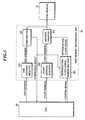
Fig. 1 is a block diagram showing a configuration of an ultrasonic diagnostic apparatus according to the first embodiment of the present invention. The ultrasonicdiagnostic apparatus 1 includes anultrasonic probe 10, a transmitting and receivingunit 20, a reproducingunit 30, a data analyzing and measuringunit 40, an imagesignal generating unit 50, adisplay unit 60, aninput unit 70, aCPU 80, and astorage unit 81.- The
ultrasonic probe 10 for use in contact with an object to be inspected includes pluralultrasonic transducers 10a that form a one-dimensional or two-dimensional transducer array. Theseultrasonic transducers 10a transmit ultrasonic beams to the objectbased on applied drive signals, and receive ultrasonic echoes reflected from the object to output detection signals. - Each ultrasonic transducer is configured of a vibrator in which electrodes are formed on both ends of a material havingapiezoelectricproperty (piezoelectricmaterial) such as a piezoelectric ceramic represented by PZT (Pb (lead) zirconate titanate), a polymeric piezoelectric element represented by PVDF (polyvinylidene difluoride), or the like. When a voltage is applied to the electrodes of the vibrator by transmitting pulse or continuous wave electric signals, the piezoelectric material expands and contracts. By the expansion and contraction, pulse or continuous wave ultrasonic waves are generated from the respective vibrators, and an ultrasonic beam is formed by synthesizing these ultrasonic waves. Further, the respective vibrators expand and contract by receiving propagating ultrasonic waves and generate electric signals. These electric signals are outputted as detection signals of ultrasonic waves.
- Alternatively, as the ultrasonic transducers, plural kinds of elements of different ultrasonic conversion types may be used. For example, the above-mentioned vibrators are used as elements for transmitting ultrasonic waves and photo-detection type ultrasonic transducers are used as elements for receiving ultrasonic waves. The photo-detection type ultrasonic transducer is for detecting ultrasonic waves by converting ultrasonic signals into optical signals, and configured of a Fabry-Perot resonator or fiber Bragg grating, for example.
- The
storage unit 81 is configured of a hard disk or memory, and stores software (program) for allowing theCPU 80 to execute the control of the respective parts of the ultrasonicdiagnostic apparatus 1. Therefore, theCPU 80 and the software correspond to a control unit of the ultrasonicdiagnostic apparatus 1. The control unit has a scanning control function for sequentially setting the transmission directions of ultrasonic beams and reception directions of ultrasonic echoes, a transmission control function for selecting a transmission delay pattern according to the set transmission direction, and a reception control function for selecting a reception delay pattern according to the set transmission direction. - Here, the transmission delay pattern refers to pattern data of delay time to be provided to the drive signals so as to form an ultrasonic beam in a desired direction with the ultrasonic waves transmitted by the plural
ultrasonic transducers 10a, and the reception delay pattern refers to pattern data of delay time to be provided to the detection signals so as to extract ultrasonic echoes from the desired direction with the ultrasonic waves received by the pluralultrasonic transducers 10a. Plural transmission delay patterns and reception delay patterns are stored in the storing means such as a memory or the like. - The transmitting and receiving
unit 20 includes atransmission circuit 21, areception circuit 22, and an A/D converter 23. Further, the reproducingunit 30 includes a cine-memory 31 and a cine-memory reproducing unit 32. Furthermore, the imagesignal generating unit 50 includes asignal processing part 51, a DSC (Digital Scan Converter) 52, animage processing part 53, animage memory 54, and a D/A converter 55. - The
transmission circuit 21 generates drive signals to be respectively applied to the pluralultrasonic transducers 10a, and is able to provide respective delay times to the drive signals based on the transmission delay pattern selected by theCPU 80. Thetransmission circuit 21 may adjust the delay amounts of the drive signals and supply the drive signals to theultrasonic probe 10 such that the ultrasonic waves transmitted from the pluralultrasonic transducers 10a form an ultrasonic beam, or may supply drive signals to theultrasonic probe 10 such that the ultrasonic waves transmitted at once from the pluralultrasonic transducers 10a reach the entire imaging region of the object. - The
reception circuit 22 amplifies the detection signals respectively outputtedfrom the pluralultrasonic transducers 10a, and provides respective delay times to the detection signals based on the reception delay pattern selected by theCPU 80 and adding those detection signals one another to perform reception focus processing. Due to the reception focus processing, sound ray signals (hereinafter, also referred to as "RF signals") are formed, in which the focal point of the ultrasonic echoes is narrowed. The A/D converter 23 converts the analog RF signals into digital RF signals (hereinafter, also referred to as "RF data"). - The RF data outputted f rom the A/
D converter 2 3 is inputted to the cine-memory 31 and thesignal processing part 51. The cine-memory 31 sequentially stores the RF data inputted from the A/D converter 23. Further, the cine-memory 31 inputs parameters such as depths of reflection positions of ultrasonic waves, density of scan lines, and viewing width as information on frame rate from theCPU 80 and stores it in association with the RF data. - The
signal processing part 51 corrects attenuation owing to distance on the RF data according to the depths of the reflection positions of ultrasonic waves in STC (Sensitivity Time gain Control), and then, performs envelope detection processing thereon to generate B-mode image data. - In the above-mentioned example, the detection signals subjected to reception focus processing in the
reception circuit 22 are used as RF signals, however, detection signals that have not been subjected to reception focus processing may be used as RF signals. In this case, detection signals respectively outputted from the pluralultrasonic transducers 10a are amplified in thereception circuit 22, the amplified detection signals, i.e., the RF signals are A/D-converted by the A/D converter 23 to generate RF data. The RF data is supplied to thesignal processing part 51 and stored in the cine-memory 31. The reception focus processing is digitally performed in thesignal processing part 51. - Thus, in the cine-memory reproduction mode, observation of moving images focused on a position different from that in the live mode can be made. However, in the case where the detection signals that have not been subjected to reception focus processing are used as RF signals, since the amount of data increases, in order to prevent the rise in costs, it is desirable to adopt an imaging method such as an aperture synthesis method of performing wavefront synthesis by which spatial information can be acquired at the smaller number of transmission times.
- In the case where the aperture synthesis method is adopted, the
transmission circuit 21 supplies drive signals to theultrasonic probe 10 such that ultrasonic waves transmitted from the pluralultrasonic transducers 10a at once can reach the entire imaging region of the object. Further, in the transmitting and receivingunit 20, detection signals obtained by the pluralultrasonic transducers 10a receiving ultrasonic waves at plural different times are amplified by thereception circuit 22, and the amplified detection signals are sequentially A/D converted in the A/D converter 23 to generate time-series RF data. The RF data is supplied to thesignal processing part 51 and stored in the cine-memory 31. - Further, in the image
signal generating unit 50, the time-series RF data is once stored in a memory for aperture synthesis . Furthermore, one suitable set of time-series data is selected according to the positions of the pluralultrasonic transducers 10a from the time-series RF data stored in the memory for aperture synthesis, values of the respective time-series data are added to perform wavefront synthesis, and thereby, sound ray data in which a focal point is formed on one point within the imaging region is obtained. The same processing is performed on the respective points within the imaging region. - Since the B-mode image data generated by the
signal processing part 51 is obtained by the scan system different from the normal scan system for television signals, theDSC 52 converts (raster-converts) the data into normal image data. Theimage processing part 53 performs various kinds of necessary image processing such as gradation processing on the image data inputted from theDSC 52. - The
image memory 54 stores image data inputted from theimage processing part 53. The D/A converter 55 converts the image data loaded from theimage memory 54 into analog image signals and outputs the signals to thedisplay unit 60. Thereby, in thedisplay unit 60, ultrasonic diagnostic images imaged by theultrasonic probe 10 are displayed. - The
input unit 70 includes aconsole 71 to be used by a user to operate the ultrasonicdiagnostic apparatus 1, and atouch panel 72 as user interface means to be used to display an operation screen and input instructions when reproduction of the RF data stored in the cine-memory 31 is performed (cine-memory reproduction) . As the user interface means , thedisplay unit 60 for displaying an ultrasonic diagnostic image and input means such as a mouse may be used other than thetouch panel 72. Fig. 2A shows one example of button arrangement in the console of the input unit. In the embodiment, theconsole 71 is provided with afreeze button 710 for instructing the switching between the live reproduction function and the freeze function, a cine-reproduction button 711 for instructing cine-memory reproduction, and ameasurement button 712 for instructing analysis and/or measurement using the RF data. By pushing down thefreeze button 710, cine-reproduction button 711, andmeasurement button 712, their instructions are notified to theCPU 80.Fig. 2B shows another example of the button arrangement in the console of the input unit, and this will be described later.- In the case where an ultrasonic diagnostic image is displayed by performing cine-memory reproduction, it is necessary to load the RF data stored in the cine-
memory 31 at an appropriate frame rate determined by parameters such as the depth of reflection position of ultrasonic wave, the density of scan lines, and viewing width. In the embodiment, the frame rate information to be used for determining the frame rate at the time of reproduction is stored in the cine-memory 31 with the RF data. - The
CPU 80 outputs a control signal for controlling the frequency of a reproduction clock signal to the cine-memory reproducing unit 32 based on the frame rate information loaded from the cine-memory 31. The cine-memory reproducing unit 32 generates the reproduction clock signal having the frequency according to the control signal inputted from theCPU 80. Thus, based on the frame rate information, the frequency of the reproduction clock signal, and further, the frame rate at the time of reproduction are determined. The cine-memory reproducing unit 32 generates address information of the RF data to be loaded from the cine-memory 31 in synchronization with the reproduction clock signal and outputs the address information to the cine-memory 31. Fig. 3 is a block diagram showing a configuration of the cine-memory reproducing unit. The cine-memory reproducing unit 32 includes a reproduction clocksignal generating part 321, astart address register 322, anend address register 323, anaddress counter 324, and acomparator 325. Thestart address register 322 inputs the start address of the RF data from theCPU 80 and stores it. The end address register 323 inputs the end address of the RF data from theCPU 80 and stores it.- In the case where the ultrasonic diagnostic image is displayed by performing cine-memory reproduction, the reproduction clock
signal generating part 321 inputs the control signal generated by theCPU 80 based on the frame rate information, generates the reproduction clock signal having the frequency adapted to the frame rate of the RF data to be loaded according to the control signal, and supplies the reproduction clock signal to theaddress counter 324. - The
address counter 324 has a counter function of inputting the start address from thestart address register 322 and incrementing the start address in synchronization with the reproduction clock signal. The address obtained by theaddress counter 324 is sequentially inputted to the cine-memory 31 and thecomparator 325. In the cine-memory reproduction, the RF data loaded from the cine-memory 31 is supplied to the imagesignal generating unit 50, and an image signal is generated. - The
comparator 325 compares the address inputted from theaddress counter 324 and the end address inputted from the end address register 323 to detect the end of the cine-memory reproduction, and outputs the detection result to theCPU 80 and the reproduction clocksignal generating part 321. When the end of the cine-memory reproduction is detected, the reproduction clocksignal generating part 321 stops the generation of the reproduction clock signal. - Referring to
Fig. 1 again, the data analyzing and measuringunit 40 has a function of performing analysis and/or measurement designated by the user of the ultrasonicdiagnostic apparatus 1. In the embodiment, the data analyzing and measuringunit 40 is able to perform tissue part distortion analysis (hardness diagnosis), bloodstream measurement, tissue part motion measurement, or IMT (Intima-Media Thickness) value measurement. When the user pushes down themeasurement button 712 of theconsole 71, the data analyzing and measuringunit 40 performs desired analysis and/or measurementbasedon the RF data inputted from the A/D converter 23 or the cine-memory 31. The analysis result and/or measurement result is outputted to theDSC 52 of the imagesignal generating unit 50, and inserted to the ultrasonic tomographic image by theDSC 52. - The
CPU 80 controls the respective functional blocks according to the operation mode of the ultrasonicdiagnostic apparatus 1. For example, when the user pushed down thefreeze button 710 of theconsole 71, theCPU 80 controls the transmitting and receiving unit to switch between the live state and the freeze state. Further, the data analyzing and measuringunit 40,signal processing part 51,DSC 52, andimage processing part 53 may be configured of theCPU 80 and software (program). - Here, the operation of the ultrasonic
diagnostic apparatus 1 in the live mode will be explained with reference toFigs. 1 and2 . - The live mode refers to a mode in which display and analysis and/or measurement of ultrasonic images is performed based on RF data obtained by bringing the ultrasonic probe in contact with the object and transmitting and receiving ultrasonic waves. In the live mode, the digital RF signal outputted from the A/
D converter 23 is processed in thesignal processing part 51 and B-mode image data is generated. Simultaneously, the cine-memory 31 sequentially stores the RF data inputted from the A/D converter 23. - The
DSC 52 converts the B-mode image data into image data for normal scan system. Theimage processing part 53 performs various kinds of image processing such as gradation processing on the image data inputted from theDSC 52. Theimage memory 54 stores the image data converted by theDSC 52. The D/A converter 55 converts the image data loaded form theimage memory 54 into an analog image signal and outputs it to thedisplay unit 60. Thereby, in thedisplay unit 60, the ultrasonic diagnostic image imaged by theultrasonic probe 10 is displayed. - The user is able to acquire a desired still image by pushing down the
freeze button 710 when observing the moving images in the live mode, and specify the ROI. Further, the user is able to allow the data analyzing and measuringunit 40 to perform desired analysis and/or measurement based on the RF data that has not been subjected to image processing by pushing down themeasurement button 712. - Next, the operation of the ultrasonic
diagnostic apparatus 1 in the cine-memory reproduction mode will be explained with reference toFigs. 1-4B . - The cine-memory reproduction mode refers to a mode in which display and analysis and/or measurement of ultrasonic images is performed based on RF data stored in the cine-
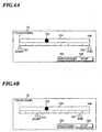
memory 31. In the cine-memory reproduction mode, imaging of the object is not necessary. When the user pushes down the cine-memory reproduction button 711, a screen shown inFig. 4A is displayed on thetouch panel 72. Fig. 4A shows an example of the screen displayed on the touch panel in the cine-memory reproduction mode. When the reproduction time of RF data stored in the cine-memory 31 is very long, it is desirable that the user can reproduce only the desired time zone. On the screen of the touch panel shown inFig. 4A , reproduction in the desired time zone can be designated by astart pointer 721 and anend pointer 722 on areproduction bar 724. Thestart pointer 721 and theend pointer 722 are horizontally slidable on thereproduction bar 724, and therefore, thestart pointer 721 and theend pointer 722 can be designated as shown inFig. 4B , for example. InFigs. 4A and 4B , areproduction pointer 723 indicates the point that is currently reproduced, and moves from left to right on thereproduction bar 724 in real time.- After the user designates the
start pointer 721 and theend pointer 722, by pushing down anexecution button 725 on thetouch panel 72, the RF data in the designated region is loaded from the cine-memory 31 and reproduction of the ultrasonic tomographic image (cine-memory reproduction) is performed on the loaded RF data. - When the user pushes down the
execution button 725 on thetouch panel 72, theCPU 80 stores as the start address the address of the RF data corresponding to thestart pointer 721 in the start address register 322 of the cine-memory reproducing unit 32. Similarly, theCPU 80 stores as the end address the address of the RF data corresponding to theend pointer 722 in the end address register 323 of the cine-memory reproducing unit 32. - Further, the
CPU 80 generates the control signal based on the frame rate information loaded from the cine-memory 31 and outputs the control signal to the reproduction clocksignal generating part 321 of the cine-memory reproducing unit 32. The reproduction clocksignal generating part 321 generates a reproduction clock signal having a frequency according to the inputted control signal and supplies it to theaddress counter 324. - The
address counter 324 starts operation when supplied with the reproduction clock signal from the reproduction clocksignal generating part 321, and acquires the start address from thestart address register 322. Theaddress counter 324 increments the count value in synchronization with the clock signal by using the start address as the initial value of the count value. The count value obtained by theaddress counter 324 is outputted to the cine-memory 31 and thecomparator 325 as address information. - When the address information is inputted from the
address counter 324 to the cine-memory 31, the RF data corresponding to the address information stored in the cine-memory 31 is loaded and outputted to thesignal processing part 51. Here, since the generation of the address information is performed in synchronization with the reproduction clock signal generated in the reproduction clocksignal generating part 321, the loading of the RF data from the cine-memory 31 is performed at the same frame rate as that in the live mode. That is, in the cine-memory reproduction mode, reproduction of the ultrasonic diagnostic image is performed at the same frame rate as that in the live mode. - In the cine-memory reproduction mode, on the
touch panel 72, thereproduction pointer 723 moves from the position of the designatedstart pointer 721 to the position of the designatedend pointer 722. Alternatively, the user is able to stop the cine-memory reproduction by pushing down astop button 726 on thetouch panel 72 during the cine-memory reproduction. Thus, desired analysis and/or measurement can be performed by pushing down thestop button 726 to acquire a desired still image and identify ROI. - In the case where analysis and/or measurement using RF data is performed, the user operates the
input unit 70 to designate desired analysis and/or measurement, and then, pushes down themeasurement button 712 of theinput unit 70. TheCPU 80 receives the signal from theinput unit 70 and instructs the designated analysis and/or measurement to the data analyzing and measuringunit 40. The data analyzing and measuringunit 40 performs the designated data analysis and/or measurement based on the RF data loaded from the cine-memory 31. The data analysis result and/or measurement result obtained in the data analyzing and measuringunit 40 is outputted to thedisplay unit 60 via theDSC 52 and so on, and displayed on thedisplay unit 60. - The
comparator 325 compares the end address stored in theend address register 323 and the address inputted from theaddress counter 324. When thecomparator 325 detects that the address information inputted from theaddress counter 324 reaches the end address, it notifies theCPU 80 and the reproduction clocksignal generating part 321 of the detection result. - Thereby, when the
reproduction pointer 723 moves to theend pointer 722 on thetouch panel 72, theCPU 80 ends the cine-memory reproduction. Here, cine-loop reproduction for continuously loop-reproducing the ultrasonic diagnostic image may be performed by theCPU 80 setting-the start address in the start address register 322 again. - Generally, in hardness diagnosis, moving image observation is important to recognize a lesion part. For example, when a hardened tissue part is diagnosed in the beat of a heart or the like, the hardened tissue part is slower in motion than other normal tissue parts. In this case, moving image observation as that in the live is effective for diagnosis.
- In the embodiment, since the moving image reproduction at the same frame rate as that in the live mode can be realized in the cine-memory reproduction, the same moving image observation as that in the live mode can be performed even when the object is notpresent. Further, since the cine-memory reproduction is performed by using RF data that has not been subjected to image processing, desired data analysis and/or measurement can be performed by identifying ROI while changing parameters such as the scaling factor, gain, contrast, and STC during the cine-memory reproduction. Here, since the timing with which the
ultrasonic probe 10 transmits or receives ultrasonic waves differs according to the depth of the diagnostic location (reflection positions of the ultrasonic waves), the scan system of theultrasonic probe 10, or the like, the motion of the object can be faithfully reproduced by reproducing the RF data stored in the cine-memory 31 at an appropriate frame rate. - Next, the second embodiment of the present invention will be explained.
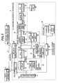
Fig. 5 is a block diagram showing a configuration of an ultrasonic diagnostic system including an ultrasonic diagnostic apparatus according to the second embodiment of the present invention. The ultrasonic diagnostic apparatus according to the second embodiment has an RFdata compressing unit 90 and acommunication unit 100 in addition to the configuration of the ultrasonic diagnostic apparatus according to the first embodiment shown inFig. 1 . Thecommunication unit 100 is connected to a data analysis andmeasurement apparatus 3 and a data accumulation apparatus 4 via anetwork 5, and makes communication between these apparatuses and itself.- The data accumulation apparatus 4 manages patient information such as patient ID and examination information such as examination ID, and an HDD (Hard Disc Drive), a file server, or the like may be used as the data accumulation apparatus 4. As the
network 5, for example, LAN (Local Area Network) such as Ethernet (registered trade mark), WAN (Wide Area Network), Internet, or wireless LAN for transmitting and receiving data with wireless communication may be used. - In
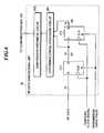
Fig. 5 , the RF data outputted from the A/D converter 23 or the cine-memory 31 is inputted to the RFdata compressing unit 90. The RFdata compressing unit 90 performs data compression processing on the RF data. The RF data that has subjected to the compression processing by the RFdata compressing unit 90 and the frame rate information outputted from theCPU 80 are transmitted from thecommunication unit 100 via thenetwork 5 to the data accumulation apparatus 4. The data accumulation apparatus 4 accumulates the received RF data and frame rate information. - The RF data inputted to the RF
data compressing unit 90 may be data obtained by A/D-converting RF signals generated by amplifying detection signals respectively outputted from the pluralultrasonic transducers 10a and adjusting the delay amounts of the detection signals and adding them one another, or may be data obtained by A/D-converting RF signals generated by amplifying detection signals respectively outputted from the pluralultrasonic transducers 10a. Fig. 6 is a block diagram showing a configuration of the RF data compressing unit included in the ultrasonic diagnostic apparatus shown inFig. 5 . The RFdata compressing unit 90 includes D-flip-flops FF1 and FF2 , a differencecoding processing circuit 901, and acompression arithmetic circuit 902. In the embodiment, RF data is 16-bit data.- RF data is inputted to the input terminal D of the flip-flop FF1. The output signal Q1 of the flip-flop FF1 is inputted to the data input terminal D of the flip-flop FF2. Further, the output signal Q1 of the flip-flop FF1 and the output signal Q2 of the flip-flop FF2 are inputted to the difference
coding processing circuit 901 and difference coding processing is performed thereon. The data outputted from the differencecoding processing circuit 901 is inputted to thecompression arithmetic circuit 902, data compression is performed thereon in thecompression arithmetic circuit 902, and then, the compressed data is outputted to thecommunication unit 100. - Further, sampling clock signals having a frequency four to eight times the frequency of the ultrasonic waves (the frequency of the drive signals or detection signals) are inputted to clock signal input terminals CLK of the flip-flops FF1 and FF2 . The frequency of the sampling clock signals is determined according to the design condition because it has influence on the difference coding of the RF data.
- Furthermore, transmission timing pulses are inputted to reset terminals R of the flip-flops FF1 and FF2 . When data transmission is not performed, the transmission timingpulses are set to reset the flip-flops FF1 and FF2. On the other hand, when data transmission is performed, the transmission timing pulses are set to operate the flip-flops FF1 and FF2, and output data Q1 and Q2 of the flip-flops FF1 and FF2 are outputted to the difference
coding processing circuit 901. The differencecoding processing circuit 901 performs difference coding processing by using the output data Q1 and Q2 of the flip-flops FF1 and FF2. - In the difference coding processing, data on the Nth sampling point and data on the (N-l)th sampling point are extracted by using the D-flip-flop and a difference is obtained by subtracting one from the other, and thereby, statistical deviation is caused in the data to make the value of data smaller.
- For example, the
compression arithmetic circuit 902 calculates a run length and performs Huffman coding processing on the data that has been subjected to difference coding processing, and thereby, compresses the data. Alternatively, the compressed data may be formed by shortening the bit lengths of the data that has been subjected to difference coding processing and packing the plural data in thecompression arithmetic circuit 902. - In the ultrasonic diagnostic system, the mode, in which diagnoses are made by acquiring ultrasonic images by using the ultrasonic
diagnostic apparatus 2 connected to the data analysis andmeasurement apparatus 3 via thenetwork 5, is referred to as "online diagnostic mode" . On the other hand, the mode, in which diagnoses are made by using the data analysis andmeasurement apparatus 3 under a condition that the ultrasonicdiagnostic apparatus 2 is not connected to thenetwork 5 or power of the ultrasonicdiagnostic apparatus 2 is not on, is referred to as "offline diagnostic mode". Fig. 7 is a block diagram showing a configuration of the data analysis and measurement apparatus included in the ultrasonic diagnostic system shown inFig. 5 . The data analysis andmeasurement apparatus 3 includes a reproducingunit 30, a data analyzing and measuringunit 40, an imagesignal generating unit 50, adisplay unit 60, aninput unit 70, aCPU 80, astorage unit 81, acommunication unit 100, and an RFdata decompressing unit 110 . The data analysis andmeasurement apparatus 3 may be configured by employing a workstation for image processing or personal computer.- The
communication unit 100 receives the compressed RF data with the frame rate information from the data accumulation apparatus 4 via the network, outputs the compressed RF data to the RFdata decompressing unit 110, and outputs the frame rate information to the cine-memory 31. - The RF
data decompressing unit 110 performs data decompression processing, which is opposite to the data compression processing in the RFdata compressing unit 90 of the ultrasonicdiagnostic apparatus 2, on the compressed RF data inputted from thecommunication unit 100. The RF data that has been subjected to data decompression processing is outputted to the cine-memory 31, and stored with the frame rate information in the cine-memory 31. Cine-memory reproduction can be performed based on the RF data and frame rate information stored in the cine-memory 31. - Next, the
input unit 70 of the data analysis andmeasurement apparatus 3 will be explained. Fig. 2B shows an example of button arrangement on a console of the input unit. In the embodiment, a cine-reproduction button 711 for instructing cine-memory reproduction and ameasurement button 712 for instructing analysis and/or measurement using RF data are provided on theconsole 71. When the cine-reproduction button 711 or themeasurement button 712 is pushed down, its instruction is notified to theCPU 80. In the data analysis andmeasurement apparatus 3, thefreeze button 710 as shown inFig. 2A is not necessary because the live-mode diagnosis using theultrasonic probe 10 is notmade. In the data analysis andmeasurement apparatus 3, when the cine-reproduction button 711 on theconsole 71 is pushed down, a screen shown inFig. 4A is displayed on the touch panel provided in theinput unit 70. The operation of the input unit is the same as that described in the first embodiment.- Here, the operation in the online diagnostic mode of the ultrasonic diagnostic system shown in
Fig. 5 will be explained with reference toFig. 8. Fig. 8 is a flowchart showing the operation in the online diagnostic mode of the ultrasonic diagnostic system. - When the online diagnosis is started, first, at step S10, patient information and examination information are transmitted from the ultrasonic
diagnostic apparatus 2 via thenetwork 5 to the data accumulation apparatus 4 according to the user' s operation at the ultrasonicdiagnostic apparatus 2 , and a corresponding examination record of the examination records accumulated in the data accumulation apparatus 4 is opened. - At step S11, ultrasonic imaging in the live mode is performed by using the ultrasonic
diagnostic apparatus 2. At this time, the ultrasonic diagnostic images of the object are displayed on the display unit and the generated RF data is stored in the cine-memory 31. - The user identifies ROI and instructs desired data analysis and/or measurement based on the ultrasonic diagnostic images obtained in the live mode or cine-memory reproduction mode. When instructing data analysis and/or measurement, the user pushes down the measurement button 712 (
Fig. 2A ) on theconsole 71. When themeasurement button 712 is pushed down, the data analyzing and measuringunit 40 performs the designated data analysis and/or measurement based on the RF data outputted from the A/D converter 23 or cine-memory 31. - At step S12, the RF data outputted from the A/
D converter 23 or cine-memory 31 is data-compressed in the RFdata compressing unit 90, transmitted with the frame rate information from the ultrasonicdiagnostic apparatus 2 via thenetwork 5 to the data accumulation apparatus 4, and stored in the data accumulation apparatus 4. Thereby, the RF data can be centrally managed with the patient information and examination information and the diagnostic results on thenetwork 5, and the storage capacity for accumulating the data in the ultrasonicdiagnostic apparatus 2 can be reduced for suppressing costs. - At step S13, when the user operates to end examination, information representing the examination end is transmitted from the ultrasonic
diagnostic apparatus 2 via thenetwork 5 to the data accumulation apparatus 4, and the examination record stored in the data accumulation apparatus 4 is closed. - Next, the operation in the offline diagnostic mode of the ultrasonic diagnostic system shown in
Fig. 5 will be explained with reference toFigs. 7 and9. Fig. 9 is a flowchart showing the operation in the offline diagnostic mode of the ultrasonic diagnostic system. - When the offline diagnosis is started, first, at step S20, patient information and examination information are transmitted from the ultrasonic
diagnostic apparatus 2 via thenetwork 5 to the data accumulation apparatus 4 according to the user' s operation at the data analysis andmeasurement apparatus 3, and a corresponding examination record of the examination records accumulated in the data accumulation apparatus 4 is opened. - At step S21, the data analysis and
measurement apparatus 3 loads the compressed RF data included in the corresponding examination record with the frame rate information from the data accumulation apparatus 4 via thenetwork 5. This RF data is the RF data transmitted from the ultrasonicdiagnostic apparatus 2 to the data accumulation apparatus 4 in the online mode. When the data analysis andmeasurement apparatus 3 acquires the RF data and the frame rate information from the data accumulation apparatus 4, the RFdata decompressing unit 110 decompresses the RF data by performing decompression processing on the compressed RF data. - At step S22, the decompressed RF data is stored in the cine-
memory 31 with the frame rate information, and the same processing as that in the ultrasonicdiagnostic apparatus 2 in the online mode is performed thereon. That is, the RF data is loaded from the cine-memory 31 according to the operation of theconsole 71 by the user, processed in thesignal processing part 51, theDSC 52, theimage processing part 53, theimage memory 54, and the D/A converter 55, and thereby, ultrasonic diagnostic images are displayed on thedisplay unit 60. - The user identifies ROI and instructs desired data analysis and/or measurement based on the ultrasonic diagnostic images obtained in the cine-memory reproduction mode. When instructing data analysis and/or measurement, the user pushes down the measurement button 712 (
Fig. 2B ) on theconsole 71. When themeasurement button 712 is pushed down, the data analyzing and measuringunit 40 loads the RF data from the cine-memory 31 and performs the designated data analysis and/or measurement. Since the RF data loaded from the cine-memory 31 has not been subjected to image display processing, it is preferable for use in data analysis and/or measurement of IMT value measurement or the like. Therefore, diagnoses with high accuracy can be realized. - At step S23, when the user operates to end examination, information representing the examination end is transmitted from the ultrasonic
diagnostic apparatus 2 via thenetwork 5 to the data accumulation apparatus 4, and the examination record stored in the data accumulation apparatus 4 are closed.
Claims (12)
- An ultrasonic diagnostic apparatus comprising:an ultrasonic probe (10) including plural ultrasonic transducers (10a) for transmitting ultrasonic waves to an object to be inspected according to drive signals and receiving ultrasonic echoes reflected from the object to output detection signals;a transmitting and receiving unit (20) for supplying the drive signals to said ultrasonic probe (10), generating RF signals based on the detection signals, and A/D-converting the RF signals to generate RF data;a cine-memory (31) for storing the RF data generated by said transmitting and receiving unit (20) with information on frame rate;a cine-memory reproducing unit (32);a data analyzing and measuring unit (40) for performing analysis and/or measurement on a selected region of interest based on RF data;an image signal generating unit (50) for generating an image signal; anda display unit (60) for displaying an ultrasonic image based on the image signal generated by said image signal generating unit (50),characterized in that said cine-memory reproducing unit (32) is adapted to generate address information of the RF data in synchronization with a clock signal having a frequency controlled based on the information on frame rate stored in said cine-memory (31) when the RF data is loaded from said cine-memory (31), that said data analysing and measuring unit (40) is adapted to perform analysis and/or measurement selectively on either the RF data generated by said transmitting and receiving unit (20) or the RF data loaded from said cine-memory (31), and said image signal generating unit (50) is adapted to generate an image signal selectively based on the RF data generated by said transmitting and receiving unit (20) or the RF data loaded from said cine-memory (31).
- An ultrasonic diagnostic apparatus according to claim 1, wherein said transmitting and receiving unit (20) adjusts delay amounts of the drive signals and supplies the drive signals to said ultrasonic probe (10) such that ultrasonic waves transmitted from said plural ultrasonic transducers (10a) form an ultrasonic beam.
- An ultrasonic diagnostic apparatus according to claim 1, wherein said transmitting and receiving unit (20) supplies the drive signals to said ultrasonic probe (10) such that ultrasonic waves transmitted at once from said plural ultrasonic transducers (10a) reach an entire imaging region of the object.
- An ultrasonic diagnostic apparatus according to claim 1, wherein said transmitting and receiving unit (20) generates the RF signals by amplifying the detection signals outputted from said plural ultrasonic transducers (10a), adjusting delay amounts of the detection signals, and adding the detection signals one another.
- An ultrasonic diagnostic apparatus according to claim 1, wherein said transmitting and receiving unit (20) generates the RF signals by amplifying the detection signals outputted from said plural ultrasonic transducers (10a).
- An ultrasonic diagnostic apparatus according to claim 3, wherein said transmitting and receiving unit (20) generates the RF signals by performing wavefront synthesis based on the detection signals obtained by receiving the ultrasonic echoes at plural different times.
- An ultrasonic diagnostic apparatus according to any one of claims 1-6, further comprising:a control unit (80) for controlling the frequency of said clock signal based on the information on frame rate stored in said cine-memory (31).
- An ultrasonic diagnostic apparatus according to any one of claims 1-6, further comprising:an input unit (70) to be used for setting a desired reproduction start point and/or a desired reproduction end point when the RF data is loaded from said cine-memory (31) and a moving image is reproduced; anda control unit (80) for outputting information for designating a range of address to be used when the RF data is loaded from said cine-memory (31) to said cine-memory reproducing unit (32) according to the reproduction start point and/or the reproduction end point set by using said input unit (70).
- An ultrasonic diagnostic apparatus according to any one of claims 1-8, further comprising:an RF data compressing unit (90) for compressing the RF data generated by said transmitting and receiving unit (20) according to a data compression method including difference coding processing; anda communication unit (100) for transmitting the RF data compressed by said RF data compressing unit (90) with the information on frame rate to an external apparatus via a network.
- A data analysis and measurement apparatus connected via a network to an ultrasonic diagnostic apparatus (2) according to claim 9 and a data accumulation apparatus (4) for accumulating compressed RF data with the information on frame rate, said data analysis and measurement apparatus comprising:a communication unit (100) for receiving the compressed RF data with the information on frame rate from said data accumulation apparatus (4) via a network;a data decompressing unit (110) for decompressing the compressed RF data received by said communication unit (100) ;a cine-memory (31) for storing the RF data decompressed by said data decompressing unit (110) with the information on frame rate;a cine-memory reproducing unit (32) for generating address information of the RF data in synchronization with a clock signal having a frequency controlled based on the information on frame rate stored in said cine-memory (31) when the RF data is loaded from said cine-memory (31);a data analyzing and measuring unit (40) for performing analysis and/or measurement on a selected region of interest based on the RF data loaded from said cine-memory (31);an image signal generating unit (50) for generating an image signal based on the RF data loaded from said cine-memory (31); anda display unit (60) for displaying an ultrasonic image based on the image signal generated by said image signal generating unit (50).
- A data analysis and measurement apparatus according to claim 10, further comprising:a control unit (80) for controlling the frequency of said clock signal based on the information on frame rate stored in said cine-memory (31).
- A data analysis and measurement apparatus according to claim 10 or 11, further comprising:an input unit (70) to be used for setting a desired reproduction start point and/or a desired reproduction end point when the RF data is loaded from said cine-memory (31) and a moving image is reproduced; anda control unit (80) for outputting information for designating a range of address to be used when the RF data is loaded from said cine-memory (31) to said cine-memory reproducing unit (32) according to the reproduction start point and/or reproduction end point set by using said input unit (70).
Applications Claiming Priority (1)
| Application Number | Priority Date | Filing Date | Title |
|---|---|---|---|
| JP2006088899AJP4713382B2 (en) | 2006-03-28 | 2006-03-28 | Ultrasonic diagnostic apparatus and data analysis measurement apparatus |
Publications (3)
| Publication Number | Publication Date |
|---|---|
| EP1840594A2 EP1840594A2 (en) | 2007-10-03 |
| EP1840594A3 EP1840594A3 (en) | 2011-01-12 |
| EP1840594B1true EP1840594B1 (en) | 2012-06-06 |
Family
ID=38324168
Family Applications (1)
| Application Number | Title | Priority Date | Filing Date |
|---|---|---|---|
| EP20070005391Not-in-forceEP1840594B1 (en) | 2006-03-28 | 2007-03-15 | Ultrasonic diagnostic apparatus and data analysis and measurement apparatus |
Country Status (3)
| Country | Link |
|---|---|
| US (1) | US20070232925A1 (en) |
| EP (1) | EP1840594B1 (en) |
| JP (1) | JP4713382B2 (en) |
Cited By (19)
| Publication number | Priority date | Publication date | Assignee | Title |
|---|---|---|---|---|
| US8602993B2 (en) | 2008-08-08 | 2013-12-10 | Maui Imaging, Inc. | Imaging with multiple aperture medical ultrasound and synchronization of add-on systems |
| US8684936B2 (en) | 2006-10-25 | 2014-04-01 | Maui Imaging, Inc. | Method and apparatus to produce ultrasonic images using multiple apertures |
| US9146313B2 (en) | 2006-09-14 | 2015-09-29 | Maui Imaging, Inc. | Point source transmission and speed-of-sound correction using multi-aperature ultrasound imaging |
| US9192355B2 (en) | 2006-02-06 | 2015-11-24 | Maui Imaging, Inc. | Multiple aperture ultrasound array alignment fixture |
| US9220478B2 (en) | 2010-04-14 | 2015-12-29 | Maui Imaging, Inc. | Concave ultrasound transducers and 3D arrays |
| US9265484B2 (en) | 2011-12-29 | 2016-02-23 | Maui Imaging, Inc. | M-mode ultrasound imaging of arbitrary paths |
| US9282945B2 (en) | 2009-04-14 | 2016-03-15 | Maui Imaging, Inc. | Calibration of ultrasound probes |
| US9339256B2 (en) | 2007-10-01 | 2016-05-17 | Maui Imaging, Inc. | Determining material stiffness using multiple aperture ultrasound |
| US9510806B2 (en) | 2013-03-13 | 2016-12-06 | Maui Imaging, Inc. | Alignment of ultrasound transducer arrays and multiple aperture probe assembly |
| US9572549B2 (en) | 2012-08-10 | 2017-02-21 | Maui Imaging, Inc. | Calibration of multiple aperture ultrasound probes |
| US9668714B2 (en) | 2010-04-14 | 2017-06-06 | Maui Imaging, Inc. | Systems and methods for improving ultrasound image quality by applying weighting factors |
| US9788813B2 (en) | 2010-10-13 | 2017-10-17 | Maui Imaging, Inc. | Multiple aperture probe internal apparatus and cable assemblies |
| US9883848B2 (en) | 2013-09-13 | 2018-02-06 | Maui Imaging, Inc. | Ultrasound imaging using apparent point-source transmit transducer |
| US9986969B2 (en) | 2012-09-06 | 2018-06-05 | Maui Imaging, Inc. | Ultrasound imaging system memory architecture |
| US10226234B2 (en) | 2011-12-01 | 2019-03-12 | Maui Imaging, Inc. | Motion detection using ping-based and multiple aperture doppler ultrasound |
| US10401493B2 (en) | 2014-08-18 | 2019-09-03 | Maui Imaging, Inc. | Network-based ultrasound imaging system |
| US10856846B2 (en) | 2016-01-27 | 2020-12-08 | Maui Imaging, Inc. | Ultrasound imaging with sparse array probes |
| US12167209B2 (en) | 2012-09-06 | 2024-12-10 | Maui Imaging, Inc. | Ultrasound imaging system memory architecture |
| US12190627B2 (en) | 2015-03-30 | 2025-01-07 | Maui Imaging, Inc. | Ultrasound imaging systems and methods for detecting object motion |
Families Citing this family (14)
| Publication number | Priority date | Publication date | Assignee | Title |
|---|---|---|---|---|
| JP5300188B2 (en)* | 2006-09-11 | 2013-09-25 | 株式会社東芝 | Ultrasonic diagnostic apparatus and control program for ultrasonic diagnostic apparatus |
| FR2934695B1 (en)* | 2008-07-31 | 2011-07-15 | Intelligence In Medical Technologies | METHOD AND SYSTEM FOR CENTRALIZING IMAGE CONSTRUCTION |
| JP5346555B2 (en)* | 2008-11-04 | 2013-11-20 | 富士フイルム株式会社 | Ultrasound diagnostic device with arteriosclerosis risk display function |
| US9826959B2 (en)* | 2008-11-04 | 2017-11-28 | Fujifilm Corporation | Ultrasonic diagnostic device |
| JPWO2010055816A1 (en)* | 2008-11-14 | 2012-04-12 | 株式会社日立メディコ | Ultrasound diagnostic apparatus and standard image data generation method for ultrasonic diagnostic apparatus |
| CN102238915B (en)* | 2008-12-02 | 2014-12-03 | 株式会社东芝 | Ultrasonic diagnostic device, Doppler measuring device, and Doppler measuring method |
| US8157738B2 (en)* | 2009-06-02 | 2012-04-17 | Samplify Systems, Inc. | Ultrasound signal compression |
| US8317706B2 (en)* | 2009-06-29 | 2012-11-27 | White Eagle Sonic Technologies, Inc. | Post-beamforming compression in ultrasound systems |
| JP5389722B2 (en)* | 2009-09-30 | 2014-01-15 | 富士フイルム株式会社 | Ultrasonic diagnostic apparatus and method for operating the same |
| KR101335724B1 (en) | 2010-08-09 | 2013-12-04 | 삼성전자주식회사 | Ultrasonic diagnostic apparatus and control method thereof |
| JP5653125B2 (en)* | 2010-08-19 | 2015-01-14 | キヤノン株式会社 | Subject information acquisition device |
| JP5292440B2 (en)* | 2011-06-03 | 2013-09-18 | 富士フイルム株式会社 | Ultrasonic diagnostic equipment |
| EP2762079A4 (en)* | 2011-09-30 | 2015-04-29 | Hitachi Medical Corp | Diagnostic x-ray imaging equipment and x-ray image display method |
| US20190228545A1 (en)* | 2016-09-28 | 2019-07-25 | Covidien Lp | System and method for parallelization of cpu and gpu processing for ultrasound imaging devices |
Family Cites Families (17)
| Publication number | Priority date | Publication date | Assignee | Title |
|---|---|---|---|---|
| US4317370A (en)* | 1977-06-13 | 1982-03-02 | New York Institute Of Technology | Ultrasound imaging system |
| JPH0630930A (en) | 1991-05-13 | 1994-02-08 | Yokogawa Medical Syst Ltd | Ultrasonic diagnosing apparatus |
| JPH07323030A (en)* | 1994-05-31 | 1995-12-12 | Ken Ishihara | Ultrasonic diagnostic apparatus |
| JPH07328007A (en)* | 1994-06-07 | 1995-12-19 | Ken Ishihara | Image displaying method for ultrasonic diagnostic device |
| US5469851A (en)* | 1994-08-09 | 1995-11-28 | Hewlett-Packard Company | Time multiplexed digital ultrasound beamformer |
| US5902244A (en)* | 1997-02-05 | 1999-05-11 | Olympus Optical Co., Ltd. | Ultrasonic diagnosis apparatus including simple digital scan converter |
| JP3235971B2 (en)* | 1997-04-24 | 2001-12-04 | 松下電器産業株式会社 | Cine memory control method in ultrasonic diagnostic apparatus |
| US6142946A (en)* | 1998-11-20 | 2000-11-07 | Atl Ultrasound, Inc. | Ultrasonic diagnostic imaging system with cordless scanheads |
| US6322505B1 (en)* | 1999-06-08 | 2001-11-27 | Acuson Corporation | Medical diagnostic ultrasound system and method for post processing |
| JP2001143005A (en)* | 1999-11-16 | 2001-05-25 | Nippon Koden Corp | Medical image display system |
| JP2001299745A (en) | 2000-04-21 | 2001-10-30 | Hitachi Medical Corp | Ultrasonic diagnostic instrument |
| JP4266548B2 (en)* | 2001-09-27 | 2009-05-20 | 富士フイルム株式会社 | Ultrasonic receiver and ultrasonic diagnostic apparatus using the same |
| US7418480B2 (en)* | 2001-10-25 | 2008-08-26 | Ge Medical Systems Global Technology Company, Llc | Medical imaging data streaming |
| ITSV20020052A1 (en)* | 2002-10-16 | 2004-04-17 | Esaote Spa | METHOD AND DEVICE FOR THE ACQUISITION OF ECOGRAPHIC IMAGES |
| US6951543B2 (en)* | 2003-06-24 | 2005-10-04 | Koninklijke Philips Electronics N.V. | Automatic setup system and method for ultrasound imaging systems |
| JP4469583B2 (en)* | 2003-09-11 | 2010-05-26 | 株式会社東芝 | Ultrasonic diagnostic equipment |
| JP2005118314A (en)* | 2003-10-16 | 2005-05-12 | Shimadzu Corp | Ultrasonic diagnostic equipment |
- 2006
- 2006-03-28JPJP2006088899Apatent/JP4713382B2/ennot_activeExpired - Fee Related
- 2007
- 2007-03-15EPEP20070005391patent/EP1840594B1/ennot_activeNot-in-force
- 2007-03-28USUS11/727,809patent/US20070232925A1/ennot_activeAbandoned
Cited By (42)
| Publication number | Priority date | Publication date | Assignee | Title |
|---|---|---|---|---|
| US9192355B2 (en) | 2006-02-06 | 2015-11-24 | Maui Imaging, Inc. | Multiple aperture ultrasound array alignment fixture |
| US9146313B2 (en) | 2006-09-14 | 2015-09-29 | Maui Imaging, Inc. | Point source transmission and speed-of-sound correction using multi-aperature ultrasound imaging |
| US9986975B2 (en) | 2006-09-14 | 2018-06-05 | Maui Imaging, Inc. | Point source transmission and speed-of-sound correction using multi-aperture ultrasound imaging |
| US9526475B2 (en) | 2006-09-14 | 2016-12-27 | Maui Imaging, Inc. | Point source transmission and speed-of-sound correction using multi-aperture ultrasound imaging |
| US9420994B2 (en) | 2006-10-25 | 2016-08-23 | Maui Imaging, Inc. | Method and apparatus to produce ultrasonic images using multiple apertures |
| US8684936B2 (en) | 2006-10-25 | 2014-04-01 | Maui Imaging, Inc. | Method and apparatus to produce ultrasonic images using multiple apertures |
| US9072495B2 (en) | 2006-10-25 | 2015-07-07 | Maui Imaging, Inc. | Method and apparatus to produce ultrasonic images using multiple apertures |
| US10675000B2 (en) | 2007-10-01 | 2020-06-09 | Maui Imaging, Inc. | Determining material stiffness using multiple aperture ultrasound |
| US9339256B2 (en) | 2007-10-01 | 2016-05-17 | Maui Imaging, Inc. | Determining material stiffness using multiple aperture ultrasound |
| US8602993B2 (en) | 2008-08-08 | 2013-12-10 | Maui Imaging, Inc. | Imaging with multiple aperture medical ultrasound and synchronization of add-on systems |
| US10206662B2 (en) | 2009-04-14 | 2019-02-19 | Maui Imaging, Inc. | Calibration of ultrasound probes |
| US9282945B2 (en) | 2009-04-14 | 2016-03-15 | Maui Imaging, Inc. | Calibration of ultrasound probes |
| US11051791B2 (en)* | 2009-04-14 | 2021-07-06 | Maui Imaging, Inc. | Calibration of ultrasound probes |
| US11998395B2 (en) | 2010-02-18 | 2024-06-04 | Maui Imaging, Inc. | Point source transmission and speed-of-sound correction using multi-aperture ultrasound imaging |
| US9247926B2 (en) | 2010-04-14 | 2016-02-02 | Maui Imaging, Inc. | Concave ultrasound transducers and 3D arrays |
| US11172911B2 (en) | 2010-04-14 | 2021-11-16 | Maui Imaging, Inc. | Systems and methods for improving ultrasound image quality by applying weighting factors |
| US9220478B2 (en) | 2010-04-14 | 2015-12-29 | Maui Imaging, Inc. | Concave ultrasound transducers and 3D arrays |
| US10835208B2 (en) | 2010-04-14 | 2020-11-17 | Maui Imaging, Inc. | Concave ultrasound transducers and 3D arrays |
| US9668714B2 (en) | 2010-04-14 | 2017-06-06 | Maui Imaging, Inc. | Systems and methods for improving ultrasound image quality by applying weighting factors |
| US9788813B2 (en) | 2010-10-13 | 2017-10-17 | Maui Imaging, Inc. | Multiple aperture probe internal apparatus and cable assemblies |
| US12350101B2 (en) | 2010-10-13 | 2025-07-08 | Maui Imaging, Inc. | Concave ultrasound transducers and 3D arrays |
| US10226234B2 (en) | 2011-12-01 | 2019-03-12 | Maui Imaging, Inc. | Motion detection using ping-based and multiple aperture doppler ultrasound |
| US9265484B2 (en) | 2011-12-29 | 2016-02-23 | Maui Imaging, Inc. | M-mode ultrasound imaging of arbitrary paths |
| US10617384B2 (en) | 2011-12-29 | 2020-04-14 | Maui Imaging, Inc. | M-mode ultrasound imaging of arbitrary paths |
| US12343210B2 (en) | 2012-02-21 | 2025-07-01 | Maui Imaging, Inc. | Determining material stiffness using multiple aperture ultrasound |
| US12186133B2 (en) | 2012-03-26 | 2025-01-07 | Maui Imaging, Inc. | Systems and methods for improving ultrasound image quality by applying weighting factors |
| US10064605B2 (en) | 2012-08-10 | 2018-09-04 | Maui Imaging, Inc. | Calibration of multiple aperture ultrasound probes |
| US12171621B2 (en) | 2012-08-10 | 2024-12-24 | Maui Imaging, Inc. | Calibration of multiple aperture ultrasound probes |
| US11253233B2 (en) | 2012-08-10 | 2022-02-22 | Maui Imaging, Inc. | Calibration of multiple aperture ultrasound probes |
| US9572549B2 (en) | 2012-08-10 | 2017-02-21 | Maui Imaging, Inc. | Calibration of multiple aperture ultrasound probes |
| US9986969B2 (en) | 2012-09-06 | 2018-06-05 | Maui Imaging, Inc. | Ultrasound imaging system memory architecture |
| US12167209B2 (en) | 2012-09-06 | 2024-12-10 | Maui Imaging, Inc. | Ultrasound imaging system memory architecture |
| US10267913B2 (en) | 2013-03-13 | 2019-04-23 | Maui Imaging, Inc. | Alignment of ultrasound transducer arrays and multiple aperture probe assembly |
| US9510806B2 (en) | 2013-03-13 | 2016-12-06 | Maui Imaging, Inc. | Alignment of ultrasound transducer arrays and multiple aperture probe assembly |
| US10653392B2 (en) | 2013-09-13 | 2020-05-19 | Maui Imaging, Inc. | Ultrasound imaging using apparent point-source transmit transducer |
| US9883848B2 (en) | 2013-09-13 | 2018-02-06 | Maui Imaging, Inc. | Ultrasound imaging using apparent point-source transmit transducer |
| US12426855B2 (en) | 2013-09-13 | 2025-09-30 | Maui Imaging, Inc. | Ultrasound imaging using apparent point-source transmit transducer |
| US10401493B2 (en) | 2014-08-18 | 2019-09-03 | Maui Imaging, Inc. | Network-based ultrasound imaging system |
| US12204023B2 (en) | 2014-08-18 | 2025-01-21 | Maui Imaging, Inc. | Network-based ultrasound imaging system |
| US12190627B2 (en) | 2015-03-30 | 2025-01-07 | Maui Imaging, Inc. | Ultrasound imaging systems and methods for detecting object motion |
| US10856846B2 (en) | 2016-01-27 | 2020-12-08 | Maui Imaging, Inc. | Ultrasound imaging with sparse array probes |
| US12048587B2 (en) | 2016-01-27 | 2024-07-30 | Maui Imaging, Inc. | Ultrasound imaging with sparse array probes |
Also Published As
| Publication number | Publication date |
|---|---|
| JP2007260129A (en) | 2007-10-11 |
| JP4713382B2 (en) | 2011-06-29 |
| EP1840594A3 (en) | 2011-01-12 |
| EP1840594A2 (en) | 2007-10-03 |
| US20070232925A1 (en) | 2007-10-04 |
Similar Documents
| Publication | Publication Date | Title |
|---|---|---|
| EP1840594B1 (en) | Ultrasonic diagnostic apparatus and data analysis and measurement apparatus | |
| JP5230106B2 (en) | Ultrasonic diagnostic apparatus, IMT measurement method, and IMT measurement program | |
| JP5389722B2 (en) | Ultrasonic diagnostic apparatus and method for operating the same | |
| US7520855B2 (en) | Biological tissue elasticity measurement method and ultrasonographic device | |
| US9687214B2 (en) | Ultrasonic measuring device, program, and method of controlling ultrasonic measuring device | |
| WO2012002421A1 (en) | Ultrasound diagnosis device and ultrasound diagnosis method | |
| EP1958571A2 (en) | Ultrasonic diagnostic apparatus, data measurement method, and data measurement program | |
| US8282551B2 (en) | Ultrasonic diagnostic apparatus, data analysis method, and data analysis program | |
| US20170245834A1 (en) | Ultrasonic Diagnostic Apparatus, Method Of Controlling Ultrasonic Diagnostic Apparatus, And Program | |
| US8398548B2 (en) | Ultrasound diagnostic apparatus and ultrasound diagnostic method | |
| US10143444B2 (en) | Ultrasonic signal processing device and ultrasonic signal processing method | |
| US7481769B2 (en) | Ultrasonic diagnosing apparatus | |
| JP2014124402A (en) | Ultrasonic examination apparatus, and signal processing method and program for ultrasonic examination apparatus | |
| US20100331691A1 (en) | Ultrasonic diagnosis apparatus and ultrasonic diagnosis support information providing method | |
| JP4713112B2 (en) | Ultrasonic diagnostic equipment | |
| US11051789B2 (en) | Ultrasound image diagnostic apparatus | |
| JP2005102988A (en) | Ultrasonic diagnostic apparatus | |
| JP2005245479A (en) | Ultrasonic diagnostic apparatus | |
| JP2006204594A (en) | Ultrasonic diagnostic apparatus | |
| JP5653125B2 (en) | Subject information acquisition device | |
| JP2006325955A (en) | Ultrasonic diagnostic apparatus and image processing apparatus thereof | |
| JP2025017145A (en) | Method for determining polarization voltage pulse and ultrasonic diagnostic device | |
| JP2022129871A (en) | ULTRASOUND IMAGE DIAGNOSTIC DEVICE, DISPLAY CONTROL METHOD AND DISPLAY CONTROL PROGRAM | |
| JP2010099295A (en) | Ultrasonic diagnosis apparatus and control program of the same | |
| JP2013244195A (en) | Ultrasonic signal processing apparatus and ultrasonic signal processing method |
Legal Events
| Date | Code | Title | Description |
|---|---|---|---|
| PUAI | Public reference made under article 153(3) epc to a published international application that has entered the european phase | Free format text:ORIGINAL CODE: 0009012 | |
| AK | Designated contracting states | Kind code of ref document:A2 Designated state(s):AT BE BG CH CY CZ DE DK EE ES FI FR GB GR HU IE IS IT LI LT LU LV MC MT NL PL PT RO SE SI SK TR | |
| AX | Request for extension of the european patent | Extension state:AL BA HR MK YU | |
| RIC1 | Information provided on ipc code assigned before grant | Ipc:G01S 15/89 20060101ALI20100423BHEP Ipc:A61B 8/08 20060101AFI20100423BHEP | |
| PUAL | Search report despatched | Free format text:ORIGINAL CODE: 0009013 | |
| AK | Designated contracting states | Kind code of ref document:A3 Designated state(s):AT BE BG CH CY CZ DE DK EE ES FI FR GB GR HU IE IS IT LI LT LU LV MC MT NL PL PT RO SE SI SK TR | |
| AX | Request for extension of the european patent | Extension state:AL BA HR MK RS | |
| 17P | Request for examination filed | Effective date:20110629 | |
| AKX | Designation fees paid | Designated state(s):AT BE BG CH CY CZ DE DK EE ES FI FR GB GR HU IE IS IT LI LT LU LV MC MT NL PL PT RO SE SI SK TR | |
| REG | Reference to a national code | Ref country code:DE Ref legal event code:R079 Ref document number:602007023093 Country of ref document:DE Free format text:PREVIOUS MAIN CLASS: G01S0007520000 Ipc:A61B0008080000 | |
| GRAP | Despatch of communication of intention to grant a patent | Free format text:ORIGINAL CODE: EPIDOSNIGR1 | |
| RIC1 | Information provided on ipc code assigned before grant | Ipc:A61B 8/08 20060101AFI20120117BHEP Ipc:G01S 15/89 20060101ALI20120117BHEP | |
| GRAS | Grant fee paid | Free format text:ORIGINAL CODE: EPIDOSNIGR3 | |
| GRAA | (expected) grant | Free format text:ORIGINAL CODE: 0009210 | |
| AK | Designated contracting states | Kind code of ref document:B1 Designated state(s):AT BE BG CH CY CZ DE DK EE ES FI FR GB GR HU IE IS IT LI LT LU LV MC MT NL PL PT RO SE SI SK TR | |
| REG | Reference to a national code | Ref country code:GB Ref legal event code:FG4D | |
| REG | Reference to a national code | Ref country code:CH Ref legal event code:EP Ref country code:AT Ref legal event code:REF Ref document number:560624 Country of ref document:AT Kind code of ref document:T Effective date:20120615 | |
| REG | Reference to a national code | Ref country code:IE Ref legal event code:FG4D | |
| REG | Reference to a national code | Ref country code:DE Ref legal event code:R096 Ref document number:602007023093 Country of ref document:DE Effective date:20120802 | |
| REG | Reference to a national code | Ref country code:NL Ref legal event code:VDEP Effective date:20120606 | |
| PG25 | Lapsed in a contracting state [announced via postgrant information from national office to epo] | Ref country code:SE Free format text:LAPSE BECAUSE OF FAILURE TO SUBMIT A TRANSLATION OF THE DESCRIPTION OR TO PAY THE FEE WITHIN THE PRESCRIBED TIME-LIMIT Effective date:20120606 Ref country code:LT Free format text:LAPSE BECAUSE OF FAILURE TO SUBMIT A TRANSLATION OF THE DESCRIPTION OR TO PAY THE FEE WITHIN THE PRESCRIBED TIME-LIMIT Effective date:20120606 Ref country code:FI Free format text:LAPSE BECAUSE OF FAILURE TO SUBMIT A TRANSLATION OF THE DESCRIPTION OR TO PAY THE FEE WITHIN THE PRESCRIBED TIME-LIMIT Effective date:20120606 Ref country code:CY Free format text:LAPSE BECAUSE OF FAILURE TO SUBMIT A TRANSLATION OF THE DESCRIPTION OR TO PAY THE FEE WITHIN THE PRESCRIBED TIME-LIMIT Effective date:20120606 | |
| REG | Reference to a national code | Ref country code:AT Ref legal event code:MK05 Ref document number:560624 Country of ref document:AT Kind code of ref document:T Effective date:20120606 | |
| REG | Reference to a national code | Ref country code:LT Ref legal event code:MG4D Effective date:20120606 | |
| PG25 | Lapsed in a contracting state [announced via postgrant information from national office to epo] | Ref country code:LV Free format text:LAPSE BECAUSE OF FAILURE TO SUBMIT A TRANSLATION OF THE DESCRIPTION OR TO PAY THE FEE WITHIN THE PRESCRIBED TIME-LIMIT Effective date:20120606 Ref country code:GR Free format text:LAPSE BECAUSE OF FAILURE TO SUBMIT A TRANSLATION OF THE DESCRIPTION OR TO PAY THE FEE WITHIN THE PRESCRIBED TIME-LIMIT Effective date:20120907 Ref country code:SI Free format text:LAPSE BECAUSE OF FAILURE TO SUBMIT A TRANSLATION OF THE DESCRIPTION OR TO PAY THE FEE WITHIN THE PRESCRIBED TIME-LIMIT Effective date:20120606 | |
| PG25 | Lapsed in a contracting state [announced via postgrant information from national office to epo] | Ref country code:EE Free format text:LAPSE BECAUSE OF FAILURE TO SUBMIT A TRANSLATION OF THE DESCRIPTION OR TO PAY THE FEE WITHIN THE PRESCRIBED TIME-LIMIT Effective date:20120606 Ref country code:CZ Free format text:LAPSE BECAUSE OF FAILURE TO SUBMIT A TRANSLATION OF THE DESCRIPTION OR TO PAY THE FEE WITHIN THE PRESCRIBED TIME-LIMIT Effective date:20120606 Ref country code:IS Free format text:LAPSE BECAUSE OF FAILURE TO SUBMIT A TRANSLATION OF THE DESCRIPTION OR TO PAY THE FEE WITHIN THE PRESCRIBED TIME-LIMIT Effective date:20121006 Ref country code:SK Free format text:LAPSE BECAUSE OF FAILURE TO SUBMIT A TRANSLATION OF THE DESCRIPTION OR TO PAY THE FEE WITHIN THE PRESCRIBED TIME-LIMIT Effective date:20120606 Ref country code:NL Free format text:LAPSE BECAUSE OF FAILURE TO SUBMIT A TRANSLATION OF THE DESCRIPTION OR TO PAY THE FEE WITHIN THE PRESCRIBED TIME-LIMIT Effective date:20120606 Ref country code:BE Free format text:LAPSE BECAUSE OF FAILURE TO SUBMIT A TRANSLATION OF THE DESCRIPTION OR TO PAY THE FEE WITHIN THE PRESCRIBED TIME-LIMIT Effective date:20120606 Ref country code:AT Free format text:LAPSE BECAUSE OF FAILURE TO SUBMIT A TRANSLATION OF THE DESCRIPTION OR TO PAY THE FEE WITHIN THE PRESCRIBED TIME-LIMIT Effective date:20120606 Ref country code:RO Free format text:LAPSE BECAUSE OF FAILURE TO SUBMIT A TRANSLATION OF THE DESCRIPTION OR TO PAY THE FEE WITHIN THE PRESCRIBED TIME-LIMIT Effective date:20120606 | |
| PG25 | Lapsed in a contracting state [announced via postgrant information from national office to epo] | Ref country code:PT Free format text:LAPSE BECAUSE OF FAILURE TO SUBMIT A TRANSLATION OF THE DESCRIPTION OR TO PAY THE FEE WITHIN THE PRESCRIBED TIME-LIMIT Effective date:20121008 Ref country code:IT Free format text:LAPSE BECAUSE OF FAILURE TO SUBMIT A TRANSLATION OF THE DESCRIPTION OR TO PAY THE FEE WITHIN THE PRESCRIBED TIME-LIMIT Effective date:20120606 Ref country code:PL Free format text:LAPSE BECAUSE OF FAILURE TO SUBMIT A TRANSLATION OF THE DESCRIPTION OR TO PAY THE FEE WITHIN THE PRESCRIBED TIME-LIMIT Effective date:20120606 | |
| PLBE | No opposition filed within time limit | Free format text:ORIGINAL CODE: 0009261 | |
| STAA | Information on the status of an ep patent application or granted ep patent | Free format text:STATUS: NO OPPOSITION FILED WITHIN TIME LIMIT | |
| PG25 | Lapsed in a contracting state [announced via postgrant information from national office to epo] | Ref country code:ES Free format text:LAPSE BECAUSE OF FAILURE TO SUBMIT A TRANSLATION OF THE DESCRIPTION OR TO PAY THE FEE WITHIN THE PRESCRIBED TIME-LIMIT Effective date:20120917 Ref country code:DK Free format text:LAPSE BECAUSE OF FAILURE TO SUBMIT A TRANSLATION OF THE DESCRIPTION OR TO PAY THE FEE WITHIN THE PRESCRIBED TIME-LIMIT Effective date:20120606 | |
| 26N | No opposition filed | Effective date:20130307 | |
| REG | Reference to a national code | Ref country code:DE Ref legal event code:R097 Ref document number:602007023093 Country of ref document:DE Effective date:20130307 | |
| PG25 | Lapsed in a contracting state [announced via postgrant information from national office to epo] | Ref country code:BG Free format text:LAPSE BECAUSE OF FAILURE TO SUBMIT A TRANSLATION OF THE DESCRIPTION OR TO PAY THE FEE WITHIN THE PRESCRIBED TIME-LIMIT Effective date:20120906 | |
| PG25 | Lapsed in a contracting state [announced via postgrant information from national office to epo] | Ref country code:MC Free format text:LAPSE BECAUSE OF NON-PAYMENT OF DUE FEES Effective date:20130331 | |
| REG | Reference to a national code | Ref country code:CH Ref legal event code:PL | |
| GBPC | Gb: european patent ceased through non-payment of renewal fee | Effective date:20130315 | |
| REG | Reference to a national code | Ref country code:IE Ref legal event code:MM4A | |
| PG25 | Lapsed in a contracting state [announced via postgrant information from national office to epo] | Ref country code:GB Free format text:LAPSE BECAUSE OF NON-PAYMENT OF DUE FEES Effective date:20130315 Ref country code:CH Free format text:LAPSE BECAUSE OF NON-PAYMENT OF DUE FEES Effective date:20130331 Ref country code:LI Free format text:LAPSE BECAUSE OF NON-PAYMENT OF DUE FEES Effective date:20130331 Ref country code:IE Free format text:LAPSE BECAUSE OF NON-PAYMENT OF DUE FEES Effective date:20130315 | |
| PG25 | Lapsed in a contracting state [announced via postgrant information from national office to epo] | Ref country code:MT Free format text:LAPSE BECAUSE OF FAILURE TO SUBMIT A TRANSLATION OF THE DESCRIPTION OR TO PAY THE FEE WITHIN THE PRESCRIBED TIME-LIMIT Effective date:20120606 | |
| PG25 | Lapsed in a contracting state [announced via postgrant information from national office to epo] | Ref country code:TR Free format text:LAPSE BECAUSE OF FAILURE TO SUBMIT A TRANSLATION OF THE DESCRIPTION OR TO PAY THE FEE WITHIN THE PRESCRIBED TIME-LIMIT Effective date:20120606 | |
| PG25 | Lapsed in a contracting state [announced via postgrant information from national office to epo] | Ref country code:HU Free format text:LAPSE BECAUSE OF FAILURE TO SUBMIT A TRANSLATION OF THE DESCRIPTION OR TO PAY THE FEE WITHIN THE PRESCRIBED TIME-LIMIT; INVALID AB INITIO Effective date:20070315 Ref country code:LU Free format text:LAPSE BECAUSE OF NON-PAYMENT OF DUE FEES Effective date:20130315 | |
| REG | Reference to a national code | Ref country code:FR Ref legal event code:PLFP Year of fee payment:10 | |
| PGFP | Annual fee paid to national office [announced via postgrant information from national office to epo] | Ref country code:DE Payment date:20160308 Year of fee payment:10 | |
| PGFP | Annual fee paid to national office [announced via postgrant information from national office to epo] | Ref country code:FR Payment date:20160208 Year of fee payment:10 | |
| REG | Reference to a national code | Ref country code:DE Ref legal event code:R082 Ref document number:602007023093 Country of ref document:DE Representative=s name:KLUNKER IP PATENTANWAELTE PARTG MBB, DE | |
| REG | Reference to a national code | Ref country code:DE Ref legal event code:R119 Ref document number:602007023093 Country of ref document:DE | |
| REG | Reference to a national code | Ref country code:FR Ref legal event code:ST Effective date:20171130 | |
| PG25 | Lapsed in a contracting state [announced via postgrant information from national office to epo] | Ref country code:FR Free format text:LAPSE BECAUSE OF NON-PAYMENT OF DUE FEES Effective date:20170331 Ref country code:DE Free format text:LAPSE BECAUSE OF NON-PAYMENT OF DUE FEES Effective date:20171003 |