EP1839605B1 - External fixator element having a rough ablated surface - Google Patents
External fixator element having a rough ablated surfaceDownload PDFInfo
- Publication number
- EP1839605B1 EP1839605B1EP20060112136EP06112136AEP1839605B1EP 1839605 B1EP1839605 B1EP 1839605B1EP 20060112136EP20060112136EP 20060112136EP 06112136 AEP06112136 AEP 06112136AEP 1839605 B1EP1839605 B1EP 1839605B1
- Authority
- EP
- European Patent Office
- Prior art keywords
- fibres
- external fixator
- rod
- clamping means
- contacting
- Prior art date
- Legal status (The legal status is an assumption and is not a legal conclusion. Google has not performed a legal analysis and makes no representation as to the accuracy of the status listed.)
- Active
Links
- 238000000034methodMethods0.000claimsdescription20
- 238000005488sandblastingMethods0.000claimsdescription8
- 229920002430Fibre-reinforced plasticPolymers0.000claimsdescription6
- 239000011151fibre-reinforced plasticSubstances0.000claimsdescription6
- 239000003082abrasive agentSubstances0.000claimsdescription3
- 230000001680brushing effectEffects0.000claimsdescription3
- 238000005530etchingMethods0.000claimsdescription3
- 239000004576sandSubstances0.000claimsdescription3
- CURLTUGMZLYLDI-UHFFFAOYSA-NCarbon dioxideChemical compoundO=C=OCURLTUGMZLYLDI-UHFFFAOYSA-N0.000claimsdescription2
- 239000004696Poly ether ether ketoneSubstances0.000claimsdescription2
- 229930182556PolyacetalNatural products0.000claimsdescription2
- 239000004952PolyamideSubstances0.000claimsdescription2
- 239000004743PolypropyleneSubstances0.000claimsdescription2
- 229920003235aromatic polyamidePolymers0.000claimsdescription2
- 239000011324beadSubstances0.000claimsdescription2
- JUPQTSLXMOCDHR-UHFFFAOYSA-Nbenzene-1,4-diol;bis(4-fluorophenyl)methanoneChemical compoundOC1=CC=C(O)C=C1.C1=CC(F)=CC=C1C(=O)C1=CC=C(F)C=C1JUPQTSLXMOCDHR-UHFFFAOYSA-N0.000claimsdescription2
- 235000011089carbon dioxideNutrition0.000claimsdescription2
- 150000002118epoxidesChemical class0.000claimsdescription2
- 239000011521glassSubstances0.000claimsdescription2
- 239000003365glass fiberSubstances0.000claimsdescription2
- 229910052751metalInorganic materials0.000claimsdescription2
- 239000002184metalSubstances0.000claimsdescription2
- 239000008188pelletSubstances0.000claimsdescription2
- 229920002647polyamidePolymers0.000claimsdescription2
- 229920000728polyesterPolymers0.000claimsdescription2
- 229920002530polyetherether ketonePolymers0.000claimsdescription2
- 229920006324polyoxymethylenePolymers0.000claimsdescription2
- -1polypropylenePolymers0.000claimsdescription2
- 229920001155polypropylenePolymers0.000claimsdescription2
- 239000002893slagSubstances0.000claimsdescription2
- 239000012876carrier materialSubstances0.000claims3
- 239000004033plasticSubstances0.000description22
- 229920003023plasticPolymers0.000description22
- 239000000835fiberSubstances0.000description14
- 239000000463materialSubstances0.000description14
- 210000000988bone and boneAnatomy0.000description9
- 238000005299abrasionMethods0.000description5
- 229910000831SteelInorganic materials0.000description3
- 240000008042Zea maysSpecies0.000description3
- 235000005824Zea mays ssp. parviglumisNutrition0.000description3
- 235000002017Zea mays subsp maysNutrition0.000description3
- 235000005822cornNutrition0.000description3
- 239000007789gasSubstances0.000description3
- 239000010959steelSubstances0.000description3
- MHAJPDPJQMAIIY-UHFFFAOYSA-NHydrogen peroxideChemical compoundOOMHAJPDPJQMAIIY-UHFFFAOYSA-N0.000description2
- 239000002253acidSubstances0.000description2
- 230000035876healingEffects0.000description2
- 238000001746injection mouldingMethods0.000description2
- 239000010410layerSubstances0.000description2
- 238000004519manufacturing processMethods0.000description2
- 239000000203mixtureSubstances0.000description2
- 208000003643CallositiesDiseases0.000description1
- OKTJSMMVPCPJKN-UHFFFAOYSA-NCarbonChemical compound[C]OKTJSMMVPCPJKN-UHFFFAOYSA-N0.000description1
- 239000004593EpoxySubstances0.000description1
- 206010020649HyperkeratosisDiseases0.000description1
- RTAQQCXQSZGOHL-UHFFFAOYSA-NTitaniumChemical compound[Ti]RTAQQCXQSZGOHL-UHFFFAOYSA-N0.000description1
- 239000004411aluminiumSubstances0.000description1
- 229910052782aluminiumInorganic materials0.000description1
- XAGFODPZIPBFFR-UHFFFAOYSA-NaluminiumChemical compound[Al]XAGFODPZIPBFFR-UHFFFAOYSA-N0.000description1
- 238000000071blow mouldingMethods0.000description1
- 229910052799carbonInorganic materials0.000description1
- 238000005266castingMethods0.000description1
- 230000000295complement effectEffects0.000description1
- 238000000748compression mouldingMethods0.000description1
- 238000011109contaminationMethods0.000description1
- 238000010586diagramMethods0.000description1
- 238000004512die castingMethods0.000description1
- 238000006073displacement reactionMethods0.000description1
- 238000009760electrical discharge machiningMethods0.000description1
- 230000002708enhancing effectEffects0.000description1
- 238000010097foam mouldingMethods0.000description1
- 239000007943implantSubstances0.000description1
- 208000015181infectious diseaseDiseases0.000description1
- 238000009434installationMethods0.000description1
- 238000003475laminationMethods0.000description1
- 239000003562lightweight materialSubstances0.000description1
- 230000007774longtermEffects0.000description1
- 238000005259measurementMethods0.000description1
- 238000000465mouldingMethods0.000description1
- 230000001590oxidative effectEffects0.000description1
- 239000011347resinSubstances0.000description1
- 229920005989resinPolymers0.000description1
- 238000001175rotational mouldingMethods0.000description1
- 239000000243solutionSubstances0.000description1
- 230000000087stabilizing effectEffects0.000description1
- 239000004616structural foamSubstances0.000description1
- 239000002344surface layerSubstances0.000description1
- 238000003856thermoformingMethods0.000description1
- 229920001169thermoplasticPolymers0.000description1
- 238000009757thermoplastic mouldingMethods0.000description1
- 229920001187thermosetting polymerPolymers0.000description1
- 239000004416thermosoftening plasticSubstances0.000description1
- 239000010936titaniumSubstances0.000description1
- 229910052719titaniumInorganic materials0.000description1
- 238000001721transfer mouldingMethods0.000description1
Images


Classifications
- A—HUMAN NECESSITIES
- A61—MEDICAL OR VETERINARY SCIENCE; HYGIENE
- A61B—DIAGNOSIS; SURGERY; IDENTIFICATION
- A61B17/00—Surgical instruments, devices or methods
- A61B17/56—Surgical instruments or methods for treatment of bones or joints; Devices specially adapted therefor
- A61B17/58—Surgical instruments or methods for treatment of bones or joints; Devices specially adapted therefor for osteosynthesis, e.g. bone plates, screws or setting implements
- A61B17/60—Surgical instruments or methods for treatment of bones or joints; Devices specially adapted therefor for osteosynthesis, e.g. bone plates, screws or setting implements for external osteosynthesis, e.g. distractors, contractors
- A61B17/64—Devices extending alongside the bones to be positioned
- A61B17/6466—Devices extending alongside the bones to be positioned with pin-clamps movable along a solid connecting rod
- A—HUMAN NECESSITIES
- A61—MEDICAL OR VETERINARY SCIENCE; HYGIENE
- A61B—DIAGNOSIS; SURGERY; IDENTIFICATION
- A61B17/00—Surgical instruments, devices or methods
- A61B2017/00831—Material properties
- A61B2017/00858—Material properties high friction or non-slip
Definitions
- the inventionrelates to mechanical elements that are used by external fixators according to the preamble of claim 1 and methods to manufacture such mechanical elements.
- External fixatorsare well known by prior art, for example from EP 0 806 185 . Such external fixators are used for stabilizing two parts of a fractured bone and holding the parts of the bone in the correct position during the healing process. Typically external fixators comprise several pins for bony attachment, rods for holding the position of the pins and clamping means for connecting the pins with the rods. These external fixator elements are usually made of steel, titanium or aluminium.
- An external fixator element having the features of the preamble of claim 1is known from US 2005/0038425 , wherein surfaces are roughened through spark erosion. It is known from US 5,571,103 to roughen implants for medical use through sand-blasting.
- An object of the present inventionis to provide an element, a method and a external fixator system, contributing to the enhancement of the connection between clamps and rods and pins of an external fixator.
- a external fixator elemente.g. a rod, a pin or a clamping means, that comprises at least one contacting surface with the features of claim 1. At least one of the contacting surface of the element responsible to establish connection between said element and a different external fixator element is provided with a rough ablated structure.
- ablated surfacecomprises sand-blasting, brushing or similar procedures and especially etching.
- the inventionis based on the insight that the combination plastic material - plastic material has a low friction coefficient, wherein it is possible, according to the invention to change the low friction coefficient of plastic material when fibers parts are protruding over the surface of the plastic material. Therefore an element according to the invention comprises fibres having parts protruding over the surface, thus enhancing the roughness of the surface and improving the grip of a jaw of a clamp onto a rod.
- Figure 1shows an example of an external fixator as an example.
- Such an external fixatortypically comprises several pins 103, 104, a rod 109 and clamping means 105, 106, 107, 108, these elements designated as external fixator elements.
- An external fixatoris used to stabilize and to correct the direction of a fractured bone during the healing process.
- several pins 103, here twoare introduced into the first part of the bone 101 and several pins 104, here two, are introduced into the second part of the bone 102.
- Clamping means 105, 106, 107, 108are used to establish a mechanical connection between the pins 103, 104 and the rod 109. With the aid of the rod 109 and the clamping means 105, 106, 107, 108, the direction of the first part of the bone 101 relative to the second part of the bone 102 is adjusted.
- pins 103, 104, rod 109 and clamping means 106, 107, 108, 109are designated as mechanical elements further on.
- mechanical elementis not limited to the ones just named.
- Figure 2shows schematically a part of a cross section of a mechanical element.
- Reference numeral 1designates a line being part of an untreated contacting surface of the mechanical element.
- the mechanical element shownis made out of fibre-reinforced plastic. Fibres 2 are surrounded by a carrier materiel or plastic 3.
- Such a mechanical elementcan be manufactured by a plurality of different molding techniques e.g. and including thermoplastic and thermoset injection molding, blow molding, rotational molding, thermoforming, structural foam molding, compression molding, resin transfer molding (RTM) and others.
- thermoplastic and thermoset injection moldingblow molding, rotational molding, thermoforming, structural foam molding, compression molding, resin transfer molding (RTM) and others.
- RTMresin transfer molding
- Such a mechanical elementcan be manufactured by a die-casting method.
- the fibres 2are arranged randomly. It may be seen that the fibers 2 do not extend over the surface 1. This is due to the manufacturing process of such a fibre-reinforced plastic.
- the fibres 2 placed in the mould before castingtend to stay in a distance from the surface 1, i.e. no free fibre ends are touching or are directly aligned within the uppermost surface layer.
- the tested embodiments shown in Figure 4were produced with thermoplastic moulding wherein the fibres were already mixed with the plastic material and brought together in the form.
- the portion of fibres as part of the mixturecan be chosen between 20 and 70 percent by volume, preferably between 30 and 60 percent by volume, or between 40 to 50 percent by volume.
- Figure 3shows schematically a part of a cross section of a mechanical element according to an embodiment of the invention.
- Reference numeral 4designates a roughened or treated contacting surface according to a method of the present invention of the mechanical elements for example of the rod 109.
- the material of the mechanical elementis preferably fibre-reinforced plastic.
- the plasticis reinforced by glassfibres, carbonfibres, or aramidfibres. It is even possible that cottonfibres are being used for that purpose.
- the fibreshave a length between 0.1 millimeter and 2 millimeter. Even more preferably the fibres have a length between 0.25 millimeter and 1 millimeter.
- the fibreshave a diameter between 25 micrometer and 1500 micrometer. Even more preferably the fibred have a diameter between 50 micrometer and 200 micrometer.
- the plasticis preferably a plastic chosen from the group of (in the case of injection moulding) polyamide, polypropylene, PEEK, polyacetal and (in the case of RTM, lamination or pultrusion, carbon epoxy pultrusion) polyester epoxide.
- a treated surface 4is the result of a method according to the present invention.
- the untreated surface 1will be exposed to a gas stream comprising abrasive elements.
- abrasive elementsallow a steady abrasion or removal of the surface 1. Meaning that parts of the surface 1 will be removed and the treated surface 4 results. Pressurized air may be used as a gas stream.
- the abrasive elementsare preferably chosen from the group of sand, glass beads, metal pellets, dry ice, powdered slag or powdered abrasives. However other abrasive elements that are known by the person skilled in the art may also be used.
- the size of the abrasive elementmay vary since they influence the degree of abrasion of the surface of the mechanical element. Possible sizes of abrasive elements comprise 200 micrometer to 1000 micrometer.
- the degree of abrasion of the surface 1depends on the distance between the surface 1 and the fibres 2.
- the degree of abrasion of the first surfaceis reached, when some of the fibres 2 protrude from the treated surface 4.
- a fixed part 6 of the fibre 2is still firmly connected to the plastic, a protruding part 5 of the fibre 2 protrudes from the surface 4.
- the roughness of the treated surface 4is much higher than the roughness of the untreated surface 1, thus resulting in an enhanced friction between the contacting surfaces of the mechanical elements. Due to the protrusion of the fibres 2 the friction between the contacting surfaces of the mechanical elements is increased furthermore. Measurements have shown that friction increased over 50% if the surface 4 is rough and the fibres protrude from the surface 4 accordingly in comparison to untreated surfaces. In case the protruding parts 5 of the fibres 2 fray, the friction is enhanced additionally.
- abrasive elementsremain as a (e.g. sand) corn 7 in the treated surface 4 with the result that the friction between the contacting surface is enhanced even more.
- the dimension of such embedded corns 7depend on the abrasive materials used and can be between 250 micrometer and 500 micrometer.
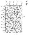
- Figure 4shows the surface 1 of a mechanical element manufactured as explained in connection with figure 2 in a microscopic zoomed view.
- the fibre content of the specimenis rather high.
- the dimension of the photographcan be seen from the bar 11 showing a length of 10 micrometer. It is clearly visible that the surface is not planar but it shows a myriad of elevations. However the height of such elevations is rather small. The height is typically in the range of several ten micrometer or can even be lower than one micrometer.
- covered fibres 12.are covered with a layer of the plastic material of the mixture. This layer of plastic material together with a corresponding plastic surface of a clamp shows said low friction coefficient.
- Figure 5shows a surface of the specimen figure 4 in a microscopic zoomed view after sand-blasting treatment.
- the photographdoes not represent the identical part of the specimen but a portion which is perhaps a millimetre apart.
- the protruding parts 5 of the fibres 6 from the schematical representationsare now visible as uncovered fibres 15.
- Parts of fibres oriented in the direction or plane of the surfaceare not longer covered by plastic material. Therefore this portion of the fibre surface having a different friction behaviour than the plastic material together with a corresponding plastic surface of a clamp shows a far higher friction coefficient.
- the elevationsare more pronounced. Additionally there are sharp fibre ends 16 protruding out of the plane of the surface of the element.
- Figure 6shows a graph of a test with a rod that has a surface of non-treated plastic and with a rod that has a treated surface according to present invention.
- the figuresshows the behaviour, if a force is applied to the connected parts, e.g. the rod is clamped using a clamp having an untreated plastic material surface.
- the failure 14arrives when connected parts start to slide; with sandblasted surface much later with higher force then without sandblasting.
- the diagramsshow the displacement of the rod against the applied force to clamp the rod.
- the untreated rodshows a slightly faster sliding 11 until approximately 400 Newton, when the failure 14 takes place.
- the treated rodcan withstand a load 13 of over 800 N until the failure happens.
- FIG 1It may be seen that the position of the contacting surfaces on the rod 109 depend on the distance between the pins 103, 104.
- the whole surface of the rod 109it is possible to designate the whole surface of the rod 109 as contacting surface. Therefore it is advantageous that whole surface of the rod 109 will be roughened, i.e. treated as described above. However it may also be possible that only parts of the surface of the rod 109 are treated. If that is the case said parts are preferably arranged in the end parts of the rod 109.
- the contacting surfaces of the clamping means 107, 108are also treated with a method as described above.
- the clamping means 107, 108comprises typically two contacting surfaces.
- a first contacting surfaceis in contact with the rod 109 and a second contacting surface is in contact with the pins 103, 104.
- the whole contact surface or just parts of itwill be treated with a method according to the present invention. It is also possible to treat both surfaces or just the first contacting surface or just the second contacting surface.
- the method as described abovemay also be applied to the pins 103, 104. But due to the fact the one end of pins is introduced into the human body, said method is preferably to be applied to other free end of the pins 103, 104 in order to prevent possible infections and pins are often made of steel.
- the surface 1will be brushed, e.g. this may be done by user a fast rotating steel brush, engaging the surface of a slowly rotating rod.
- a fast rotating steel brushcan also be introduced into the cavity of a clamp brushing one or both inner clamp surfaces as it would be in the place of a rod.
- non rotating brusheswith longitudinal movements.
- the surface 1will be etched away by means of an acid.
- the acidis applied to the surface 1 of a fibre-reinforced plastic element until the degree of removal of the surface reached the desired state an treated surface 4 results. This is the case when the fibres protrude from the surface as described above.
- the etchingcan be conducted using a strong oxidizing solution as hydrogen peroxide.
Landscapes
- Health & Medical Sciences (AREA)
- Orthopedic Medicine & Surgery (AREA)
- Life Sciences & Earth Sciences (AREA)
- Surgery (AREA)
- Biomedical Technology (AREA)
- Engineering & Computer Science (AREA)
- Nuclear Medicine, Radiotherapy & Molecular Imaging (AREA)
- Heart & Thoracic Surgery (AREA)
- Medical Informatics (AREA)
- Molecular Biology (AREA)
- Animal Behavior & Ethology (AREA)
- General Health & Medical Sciences (AREA)
- Public Health (AREA)
- Veterinary Medicine (AREA)
- Surgical Instruments (AREA)
Description
- The invention relates to mechanical elements that are used by external fixators according to the preamble of claim 1 and methods to manufacture such mechanical elements.
- External fixators are well known by prior art, for example from
EP 0 806 185 - From
US 6,702,814 it is known to use nuts or washers around the clamping screw to achieve a separate locking of rods or pins within a clamp. - Weight considerations, especially for long term patients, wearing an external fixator for extended periods of time, request a further change of material towards plastic based materials as well as the request to have X-ray transparency of the device. However it is drawback of external fixators elements of such prior art, especially when rods are made of such light weight materials, that rods may change the position relative to the clamp and therefore to other rods and pins over time due to frictional problems.
- An external fixator element having the features of the preamble of claim 1 is known from
US 2005/0038425 , wherein surfaces are roughened through spark erosion. It is known fromUS 5,571,103 to roughen implants for medical use through sand-blasting. - An object of the present invention is to provide an element, a method and a external fixator system, contributing to the enhancement of the connection between clamps and rods and pins of an external fixator.
- According to an embodiment of the invention there is provided a external fixator element, e.g. a rod, a pin or a clamping means, that comprises at least one contacting surface with the features of claim 1. At least one of the contacting surface of the element responsible to establish connection between said element and a different external fixator element is provided with a rough ablated structure.
- The term ablated surface comprises sand-blasting, brushing or similar procedures and especially etching.
- The invention is based on the insight that the combination plastic material - plastic material has a low friction coefficient, wherein it is possible, according to the invention to change the low friction coefficient of plastic material when fibers parts are protruding over the surface of the plastic material. Therefore an element according to the invention comprises fibres having parts protruding over the surface, thus enhancing the roughness of the surface and improving the grip of a jaw of a clamp onto a rod.
- The drawings will be explained in greater detail by means of a description of an exemplary embodiment, with reference to the following figures:
- Fig. 1
- shows an example of an external fixator with different external fixator elements;
- Fig. 2
- shows schematically a cross section through an external fixator element like a rod;
- Fig. 3
- shows schematically a cross section through an external fixator element according to the present invention:
- Fig. 4
- shows a microscopic zoomed image of a surface of an element like and according to
Fig. 2 ; - Fig. 5
- shows a microscopic zoomed image of a surface of an element like and according to
Fig. 4 ; and - Fig. 6
- shows diagrammatically the measured difference between a device according to prior art and a device according to the present invention.
Figure 1 shows an example of an external fixator as an example. Such an external fixator typically comprisesseveral pins rod 109 and clamping means 105, 106, 107, 108, these elements designated as external fixator elements. An external fixator is used to stabilize and to correct the direction of a fractured bone during the healing process. Typicallyseveral pins 103, here two, are introduced into the first part of thebone 101 andseveral pins 104, here two, are introduced into the second part of thebone 102. Clamping means 105, 106, 107, 108 are used to establish a mechanical connection between thepins rod 109. With the aid of therod 109 and the clamping means 105, 106, 107, 108, the direction of the first part of thebone 101 relative to the second part of thebone 102 is adjusted.- Surfaces of the
pins rod 109 and of the clamping means 105, 106, 107, 108, which face each other upon installation of the external fixators are designated as contacting surfaces. As anexample rod 109 is introduced in an opening of the clamping means 107. Thereby the surface that is covered on therod 109 by theclamping means 107 is designated as contacting surface. But also the surface that is covered by therod 109 on the clamping means 107, in this case the surface of the opening, is also designated as contacting surface. In the external fixator as shown infigure 1 , such contacting surfaces of rods have typically a cylindrical shape. Clamps may have a complementary cylindrical shape or, in a cross-section view, creating a hollow triangle, providing longitudinal lines of contact between the clamp jaw and the rod or pin. - For the sake of
simplicity pins rod 109 and clamping means 106, 107, 108, 109 are designated as mechanical elements further on. However, it is understood to the personal skilled in the art that the term mechanical element is not limited to the ones just named. Figure 2 shows schematically a part of a cross section of a mechanical element. Reference numeral 1 designates a line being part of an untreated contacting surface of the mechanical element.- In this embodiment the mechanical element shown is made out of fibre-reinforced plastic.
Fibres 2 are surrounded by a carrier materiel orplastic 3. - Such a mechanical element can be manufactured by a plurality of different molding techniques e.g. and including thermoplastic and thermoset injection molding, blow molding, rotational molding, thermoforming, structural foam molding, compression molding, resin transfer molding (RTM) and others.
- Such a mechanical element can be manufactured by a die-casting method. The
fibres 2 are arranged randomly. It may be seen that thefibers 2 do not extend over the surface 1. This is due to the manufacturing process of such a fibre-reinforced plastic. Thefibres 2 placed in the mould before casting tend to stay in a distance from the surface 1, i.e. no free fibre ends are touching or are directly aligned within the uppermost surface layer. - The tested embodiments shown in
Figure 4 were produced with thermoplastic moulding wherein the fibres were already mixed with the plastic material and brought together in the form. The portion of fibres as part of the mixture can be chosen between 20 and 70 percent by volume, preferably between 30 and 60 percent by volume, or between 40 to 50 percent by volume. Figure 3 shows schematically a part of a cross section of a mechanical element according to an embodiment of the invention.Reference numeral 4 designates a roughened or treated contacting surface according to a method of the present invention of the mechanical elements for example of therod 109.- In this first embodiment the material of the mechanical element is preferably fibre-reinforced plastic. Thereby the plastic is reinforced by glassfibres, carbonfibres, or aramidfibres. It is even possible that cottonfibres are being used for that purpose. Preferably the fibres have a length between 0.1 millimeter and 2 millimeter. Even more preferably the fibres have a length between 0.25 millimeter and 1 millimeter. Preferably the fibres have a diameter between 25 micrometer and 1500 micrometer. Even more preferably the fibred have a diameter between 50 micrometer and 200 micrometer. The plastic is preferably a plastic chosen from the group of (in the case of injection moulding) polyamide, polypropylene, PEEK, polyacetal and (in the case of RTM, lamination or pultrusion, carbon epoxy pultrusion) polyester epoxide.
- In this first embodiment a treated
surface 4 is the result of a method according to the present invention. According to this method the untreated surface 1 will be exposed to a gas stream comprising abrasive elements. This is also designated as sand-blasting. The abrasive elements allow a steady abrasion or removal of the surface 1. Meaning that parts of the surface 1 will be removed and the treatedsurface 4 results. Pressurized air may be used as a gas stream. The abrasive elements are preferably chosen from the group of sand, glass beads, metal pellets, dry ice, powdered slag or powdered abrasives. However other abrasive elements that are known by the person skilled in the art may also be used. The size of the abrasive element may vary since they influence the degree of abrasion of the surface of the mechanical element. Possible sizes of abrasive elements comprise 200 micrometer to 1000 micrometer. - The degree of abrasion of the surface 1 depends on the distance between the surface 1 and the
fibres 2. Thus the degree of abrasion of the first surface is reached, when some of thefibres 2 protrude from the treatedsurface 4. Thereby afixed part 6 of thefibre 2 is still firmly connected to the plastic, a protrudingpart 5 of thefibre 2 protrudes from thesurface 4. - Due to the sandblasting process, the roughness of the treated
surface 4 is much higher than the roughness of the untreated surface 1, thus resulting in an enhanced friction between the contacting surfaces of the mechanical elements. Due to the protrusion of thefibres 2 the friction between the contacting surfaces of the mechanical elements is increased furthermore. Measurements have shown that friction increased over 50% if thesurface 4 is rough and the fibres protrude from thesurface 4 accordingly in comparison to untreated surfaces. In case the protrudingparts 5 of thefibres 2 fray, the friction is enhanced additionally. - If the degree of abrasion is higher than necessary it is possible that some fibres will become detached from the
plastic 3. Such fibres will be removed by the pressurized gas stream of the sand blasting process. Therefore contamination due to loose fibres is not an issue. - Depending on the material of the plastic part it is also possible that some of the abrasive elements remain as a (e.g. sand)
corn 7 in the treatedsurface 4 with the result that the friction between the contacting surface is enhanced even more. The dimension of such embeddedcorns 7 depend on the abrasive materials used and can be between 250 micrometer and 500 micrometer. Figure 4 shows the surface 1 of a mechanical element manufactured as explained in connection withfigure 2 in a microscopic zoomed view. The fibre content of the specimen is rather high. The dimension of the photograph can be seen from thebar 11 showing a length of 10 micrometer. It is clearly visible that the surface is not planar but it shows a myriad of elevations. However the height of such elevations is rather small. The height is typically in the range of several ten micrometer or can even be lower than one micrometer. There can be seen coveredfibres 12. Thesefibres 12 are covered with a layer of the plastic material of the mixture. This layer of plastic material together with a corresponding plastic surface of a clamp shows said low friction coefficient.Figure 5 shows a surface of the specimenfigure 4 in a microscopic zoomed view after sand-blasting treatment. Of course, the photograph does not represent the identical part of the specimen but a portion which is perhaps a millimetre apart. In comparison tofigure 4 it may be seen that the surface has changed dramatically. The protrudingparts 5 of thefibres 6 from the schematical representations are now visible asuncovered fibres 15. There are at least two difference. Parts of fibres oriented in the direction or plane of the surface are not longer covered by plastic material. Therefore this portion of the fibre surface having a different friction behaviour than the plastic material together with a corresponding plastic surface of a clamp shows a far higher friction coefficient. Secondly the elevations are more pronounced. Additionally there are sharp fibre ends 16 protruding out of the plane of the surface of the element.Figure 6 shows a graph of a test with a rod that has a surface of non-treated plastic and with a rod that has a treated surface according to present invention. The figures shows the behaviour, if a force is applied to the connected parts, e.g. the rod is clamped using a clamp having an untreated plastic material surface. Thefailure 14 arrives when connected parts start to slide; with sandblasted surface much later with higher force then without sandblasting. The diagrams show the displacement of the rod against the applied force to clamp the rod. The untreated rod shows a slightly faster sliding 11 until approximately 400 Newton, when thefailure 14 takes place. The treated rod can withstand aload 13 of over 800 N until the failure happens.- Reference is now made to
figure 1 . It may be seen that the position of the contacting surfaces on therod 109 depend on the distance between thepins rod 109 as contacting surface. Therefore it is advantageous that whole surface of therod 109 will be roughened, i.e. treated as described above. However it may also be possible that only parts of the surface of therod 109 are treated. If that is the case said parts are preferably arranged in the end parts of therod 109. - The contacting surfaces of the clamping means 107, 108 are also treated with a method as described above. Thereby the clamping means 107, 108 comprises typically two contacting surfaces. A first contacting surface is in contact with the
rod 109 and a second contacting surface is in contact with thepins rod 109. Thereby it is possible that the whole contact surface or just parts of it will be treated with a method according to the present invention. It is also possible to treat both surfaces or just the first contacting surface or just the second contacting surface. - The method as described above may also be applied to the
pins pins - It is particularly advantageous when all the contacting surfaces of all mechanical elements will be treated by the method according to the present invention. This takes the best advantage of the method.
- But it is also possible that only certain surfaces will be treated. As an example it is possible that only the surface of the
rod 109 will be treated but not the contacting surface of the clamping means 107, 108. The friction here will be lowered. - In a further embodiment it is also possible that the surface 1 will be brushed, e.g. this may be done by user a fast rotating steel brush, engaging the surface of a slowly rotating rod. Such a brush can also be introduced into the cavity of a clamp brushing one or both inner clamp surfaces as it would be in the place of a rod. However, it is also possible to use non rotating brushes with longitudinal movements.
- In a further embodiment it is also possible that the surface 1 will be etched away by means of an acid. The acid is applied to the surface 1 of a fibre-reinforced plastic element until the degree of removal of the surface reached the desired state an treated
surface 4 results. This is the case when the fibres protrude from the surface as described above. The etching can be conducted using a strong oxidizing solution as hydrogen peroxide. - Other methods can be performed to achieve the rough ablated structure, enabling an improved grip of the external fixator element, especially when used in a set, comprising one or more clamps having treated ablated jaws clamping surfaces of rods or pins having a similar treated ablated surface.
- 1
- untreated surface
- 2
- fibre
- 3
- plastic
- 4
- roughened or treated surface
- 5
- protruding part of fibre
- 6
- fixed part of fibre
- 7
- corn
- 10
- dimension
- 11
- graph for the untreated element
- 12
- covered fibre
- 13
- graph for the treated element
- 14
- failure point
- 15
- uncovered fibre
- 16
- fibre ends
- 101
- first part of a bone
- 102
- second part of the bone
- 103
- pin
- 104
- pin
- 105
- clamping means
- 106
- clamping means
- 107
- clamping means
- 108
- clamping means
- 109
- rod
Claims (8)
- External fixator element, e.g. a rod (109), a pin (103, 104) or a clamping means (105, 106), wherein at least part of a contacting surface (4) of the element (109, 103, 104, 105, 106) responsible to establish connection between said element and a different external fixator element is provided with a rough ablated structure (4),characterized in that it is made out of a fibre-reinforced plastic that comprises a carrier material (3) and fibres (2) andin that free ends of the fibres (2) protrude from the contacting surface (4).
- External fixator element according to claim 1,characterized in that the carrier material is chosen from the group of polyamide, polypropylene, PEEK, polyacetal and polyester epoxide.
- External fixator element according to claim 1 or claim 2,characterized in that the fibres are chosen from the group of glassfibres, carbonfibres or aramidfibres.
- External fixator element according to one of claims 1 to 3,characterized in that the ablated structure (4) is formed by sand-blasting, brushing or etching.
- Method to produce a grip relevant surface of an external fixator element according to any of the claims 1 to 4,characterized in that said surface is exposed to a gas stream comprising abrasive elements until free ends of the fibres protrude from the contacting surface.
- Method according to claim 5,characterized in that the abrasive elements are chosen from the group of glass beads, metal pellets, dry ice, powdered abrasives, powdered slag or sand.
- Method, to produce a grip relevant surface of an external fixator element according to any of the claims 1 to 4,characterized in that said surface is etched until free ends of the fibres protrude from the contacting surface.
- External fixator set comprising at least two elements according to one of claims 1 to 4, comprising two rods (109) and/or pins (103, 104) and at least one clamping means (105, 106), wherein the clamping means (105, 106) is responsible to establish connection between the two rods (109) and/or pin (103, 104), wherein at least one of the contacting surfaces of the rod (109) and/or of the pin (103, 104) and/or of the clamping means (105, 106) is provided with a rough ablated structure,characterized in that said at least one of the contacting surfaces is made out of a fibre-reinforced plastic that comprises a carrier material (3) and fibres (2) andin that free ends of the fibres (2) protrude from the contacting surface (4).
Priority Applications (8)
| Application Number | Priority Date | Filing Date | Title |
|---|---|---|---|
| EP20060112136EP1839605B1 (en) | 2006-03-31 | 2006-03-31 | External fixator element having a rough ablated surface |
| ES06112136TES2318671T3 (en) | 2006-03-31 | 2006-03-31 | ELEMENT OF EXTERNAL FIXER THAT HAS AN EROSIONATED RUGOUS SURFACE. |
| DE602006004168TDE602006004168D1 (en) | 2006-03-31 | 2006-03-31 | External fixing element with a rough, worn surface |
| US11/702,935US8303587B2 (en) | 2006-03-31 | 2007-02-06 | External fixator element |
| AU2007201166AAU2007201166B2 (en) | 2006-03-31 | 2007-03-16 | External fixator element |
| CA2582168ACA2582168C (en) | 2006-03-31 | 2007-03-19 | External fixator element |
| JP2007078309AJP5118868B2 (en) | 2006-03-31 | 2007-03-26 | External fixture element |
| US13/610,008US8827999B2 (en) | 2006-03-31 | 2012-09-11 | External fixator element |
Applications Claiming Priority (1)
| Application Number | Priority Date | Filing Date | Title |
|---|---|---|---|
| EP20060112136EP1839605B1 (en) | 2006-03-31 | 2006-03-31 | External fixator element having a rough ablated surface |
Publications (2)
| Publication Number | Publication Date |
|---|---|
| EP1839605A1 EP1839605A1 (en) | 2007-10-03 |
| EP1839605B1true EP1839605B1 (en) | 2008-12-10 |
Family
ID=36922255
Family Applications (1)
| Application Number | Title | Priority Date | Filing Date |
|---|---|---|---|
| EP20060112136ActiveEP1839605B1 (en) | 2006-03-31 | 2006-03-31 | External fixator element having a rough ablated surface |
Country Status (7)
| Country | Link |
|---|---|
| US (2) | US8303587B2 (en) |
| EP (1) | EP1839605B1 (en) |
| JP (1) | JP5118868B2 (en) |
| AU (1) | AU2007201166B2 (en) |
| CA (1) | CA2582168C (en) |
| DE (1) | DE602006004168D1 (en) |
| ES (1) | ES2318671T3 (en) |
Families Citing this family (38)
| Publication number | Priority date | Publication date | Assignee | Title |
|---|---|---|---|---|
| EP2249721B1 (en)* | 2008-02-12 | 2017-07-05 | Texas Scottish Rite Hospital For Children | Fast adjust external fixation connection rod |
| JP5288938B2 (en)* | 2008-08-13 | 2013-09-11 | ケイセイ医科工業株式会社 | External fixator |
| US8858555B2 (en) | 2009-10-05 | 2014-10-14 | Stryker Trauma Sa | Dynamic external fixator and methods for use |
| EP2319436B1 (en)* | 2009-11-06 | 2013-02-13 | ORTHOFIX S.r.l. | Clamp for external orthopaedic fixing device |
| US8945128B2 (en) | 2010-08-11 | 2015-02-03 | Stryker Trauma Sa | External fixator system |
| US11141196B2 (en) | 2010-08-11 | 2021-10-12 | Stryker European Operations Holdings Llc | External fixator system |
| EP2417924B1 (en) | 2010-08-11 | 2015-07-01 | Stryker Trauma SA | External fixator system |
| EP2465455B1 (en) | 2010-12-14 | 2015-04-08 | Stryker Trauma SA | Fixation clamp |
| EP2465454B1 (en) | 2010-12-14 | 2015-04-08 | Stryker Trauma SA | Fixation clamp with thumbwheel |
| ES2540256T3 (en) | 2010-12-14 | 2015-07-09 | Stryker Trauma Sa | Fixing clamp |
| USD683461S1 (en) | 2010-12-14 | 2013-05-28 | Stryker Trauma Sa | Hinge coupling |
| USD720853S1 (en) | 2010-12-14 | 2015-01-06 | Stryker Trauma Sa | Fixation clamp |
| USD704840S1 (en) | 2010-12-14 | 2014-05-13 | Stryker Trauma Sa | Hinge coupling |
| USD682426S1 (en) | 2011-06-14 | 2013-05-14 | Stryker Trauma Sa | Fixation clamp |
| USD663030S1 (en) | 2011-06-14 | 2012-07-03 | Styker Trauma SA | Fixation clamp |
| US9101398B2 (en) | 2012-08-23 | 2015-08-11 | Stryker Trauma Sa | Bone transport external fixation frame |
| US9301782B2 (en) | 2012-09-04 | 2016-04-05 | Zimmer, Inc. | External fixation |
| US9924969B2 (en) | 2012-09-04 | 2018-03-27 | Zimmer, Inc. | External fixation |
| US9155561B2 (en) | 2013-03-06 | 2015-10-13 | Stryker Trauma Sa | Mini-rail external fixator |
| US9370380B2 (en) | 2013-03-15 | 2016-06-21 | Dne, Llc | External bone fixation system |
| ITMI20130407A1 (en)* | 2013-03-18 | 2014-09-19 | Orthofix Srl | EXTERNAL FIXING DEVICE |
| US9539030B2 (en)* | 2013-04-05 | 2017-01-10 | ApMed LLC | Multi-axis adjustable splint |
| CN103230299A (en)* | 2013-05-07 | 2013-08-07 | 张英泽 | Femoral fracture traction apparatus with good reduction fixing effect |
| US9962188B2 (en) | 2013-10-29 | 2018-05-08 | Cardinal Health 247. Inc. | External fixation system and methods of use |
| US9962187B2 (en) | 2014-08-11 | 2018-05-08 | Zimmer, Inc. | External fixation |
| WO2016040491A2 (en) | 2014-09-09 | 2016-03-17 | Integra Lifesciences Corporation | External fixation system |
| DE102014118670B4 (en)* | 2014-12-15 | 2016-06-30 | Benteler Sgl Gmbh & Co. Kg | RTM method with intermediate fiber layer |
| RU2584555C1 (en)* | 2015-02-25 | 2016-05-20 | Федеральное государственное бюджетное учреждение "Российский ордена Трудового Красного Знамени научно-исследовательский институт травматологии и ортопедии им. Р.Р. Вредена" Министерства здравоохранения Российской Федерации (ФГБУ "РНИИТО им. Р.Р. Вредена" Минздрава России) | Method for lengthening femoral bone above intramedullary rod |
| WO2016205128A2 (en) | 2015-06-17 | 2016-12-22 | Nathan Erickson | Ankle fixation system |
| US10531896B2 (en) | 2015-08-10 | 2020-01-14 | Stryker European Holdings I, Llc | Distraction tube with wire clamp |
| US11291476B2 (en) | 2016-06-10 | 2022-04-05 | Dne, Llc | External bone fixation system |
| RU2638279C1 (en)* | 2016-08-16 | 2017-12-12 | Федеральное государственное бюджетное учреждение "Российский ордена Трудового Красного Знамени научно-исследовательский институт травматологии и ортопедии им. Р.Р. Вредена" Министерства здравоохранения Российской Федерации (ФГБУ "РНИИТО им. Р.Р. Вредена" Минздрава России) | Method for femoral bone elongation along intramedullary pin |
| CN108938069B (en)* | 2018-05-29 | 2020-07-03 | 瑞安市佰益医疗器械有限公司 | A device for the treatment of femoral neck fractures |
| CN108670392B (en)* | 2018-05-29 | 2020-01-03 | 胡鹏 | Treatment device for bone fracture of hip and leg of orthopedics department |
| CN112022316A (en)* | 2020-10-10 | 2020-12-04 | 陈聚伍 | Single pole double nail external fixator |
| CN112472262A (en)* | 2020-12-11 | 2021-03-12 | 陈聚伍 | Single-rod four-nail external fixing frame for fracture |
| JP7626681B2 (en) | 2021-08-05 | 2025-02-04 | グローブライド株式会社 | Spinal Fixation Rods |
| JP2023091663A (en)* | 2021-12-20 | 2023-06-30 | 株式会社スパインテック | head pin |
Family Cites Families (28)
| Publication number | Priority date | Publication date | Assignee | Title |
|---|---|---|---|---|
| ES8302449A2 (en)* | 1981-12-09 | 1983-01-16 | Lazo De Zbikowski Juan | Functional attachment system for osteosynthesis |
| IT1181792B (en)* | 1984-11-08 | 1987-09-30 | Enrico Castaman | IMPROVEMENTS IN THE EQUIPMENT FOR THE STABILIZATION OF BONE FRACTURES |
| WO1986007568A1 (en)* | 1985-06-18 | 1986-12-31 | The Dow Chemical Company | Method for producing enhanced bonds between surfaces and articles produced by the method |
| US4620533A (en)* | 1985-09-16 | 1986-11-04 | Pfizer Hospital Products Group Inc. | External bone fixation apparatus |
| IL80661A (en)* | 1985-11-29 | 1991-07-18 | Jaquet Orthopedie | Device for positioning and securing a part having circular regions |
| US5042462A (en)* | 1990-10-30 | 1991-08-27 | Bremer Paul W | Cervical traction tongs |
| DE4303770C1 (en)* | 1993-02-09 | 1994-05-26 | Plus Endoprothetik Ag Rotkreuz | Stiffening and correction system for spinal vertebrae - comprises screw-ended holders with connecting rod supporting clamped distance pieces. |
| US5571103A (en)* | 1994-10-18 | 1996-11-05 | Bailey; Kirk J. | Method for the fixation of bone |
| US5969747A (en)* | 1995-12-19 | 1999-10-19 | Polaroid Corporation | Efficient LED light geometry for optical printers |
| AU710029B2 (en) | 1996-02-22 | 1999-09-09 | Depuy Orthopaedics, Inc. | External fixation device |
| US5891144A (en)* | 1996-05-10 | 1999-04-06 | Jaquet Orthopedie S.A. | External fixator |
| US5990380A (en)* | 1997-10-10 | 1999-11-23 | University Of Florida Research Foundation, Inc. | Percutaneous biofixed medical implants |
| US6277119B1 (en) | 1999-10-21 | 2001-08-21 | Electro-Biology, Inc. | External fixation system |
| EP1238636B1 (en)* | 2001-03-05 | 2006-08-30 | Orthofix International B.V. | External fixation device with identification means |
| US7004943B2 (en)* | 2002-02-04 | 2006-02-28 | Smith & Nephew, Inc. | Devices, systems, and methods for placing and positioning fixation elements in external fixation systems |
| US20030149436A1 (en)* | 2002-02-04 | 2003-08-07 | Mcdowell Charles L. | Fixation and compression fastener assembly for bone fractures |
| DE20202048U1 (en)* | 2002-02-11 | 2002-06-13 | Schneider, Willi, Dipl.-Ing., 97616 Bad Neustadt | Device for external fixation of broken bones |
| US6824889B2 (en)* | 2002-07-03 | 2004-11-30 | Solvay Engineered Polymers, Inc. | Platable engineered polyolefin alloys and articles containing same |
| US6796172B2 (en)* | 2002-07-31 | 2004-09-28 | Hewlett-Packard Development Company, L.P. | Flow sensor |
| JP4128966B2 (en) | 2003-02-28 | 2008-07-30 | ケイセイ医科工業株式会社 | External fixator |
| US7972616B2 (en)* | 2003-04-17 | 2011-07-05 | Nanosys, Inc. | Medical device applications of nanostructured surfaces |
| US7074294B2 (en)* | 2003-04-17 | 2006-07-11 | Nanosys, Inc. | Structures, systems and methods for joining articles and materials and uses therefor |
| US20050038498A1 (en)* | 2003-04-17 | 2005-02-17 | Nanosys, Inc. | Medical device applications of nanostructured surfaces |
| US20060122596A1 (en)* | 2003-04-17 | 2006-06-08 | Nanosys, Inc. | Structures, systems and methods for joining articles and materials and uses therefor |
| AT412546B (en)* | 2003-05-21 | 2005-04-25 | Xentis Composite Produktions & | BIKES FOR BICYCLES AND THE SAME |
| JP2005021420A (en)* | 2003-07-03 | 2005-01-27 | Dentsply Sankin Kk | Plate for osteosynthesis |
| ES2246744B1 (en)* | 2005-10-11 | 2006-12-01 | Implantvet, S.L. | ARTICULATION FOR MUTUAL SOLIDARIZATION BETWEEN BARS AND / OR NEEDLES IN AN EXTERNAL FIXING DEVICE FOR THE REDUCTION OF OSE FRACTURES. |
| US7749224B2 (en)* | 2005-12-08 | 2010-07-06 | Ebi, Llc | Foot plate fixation |
- 2006
- 2006-03-31EPEP20060112136patent/EP1839605B1/enactiveActive
- 2006-03-31DEDE602006004168Tpatent/DE602006004168D1/enactiveActive
- 2006-03-31ESES06112136Tpatent/ES2318671T3/enactiveActive
- 2007
- 2007-02-06USUS11/702,935patent/US8303587B2/enactiveActive
- 2007-03-16AUAU2007201166Apatent/AU2007201166B2/ennot_activeCeased
- 2007-03-19CACA2582168Apatent/CA2582168C/ennot_activeExpired - Fee Related
- 2007-03-26JPJP2007078309Apatent/JP5118868B2/ennot_activeExpired - Fee Related
- 2012
- 2012-09-11USUS13/610,008patent/US8827999B2/enactiveActive
Also Published As
| Publication number | Publication date |
|---|---|
| JP5118868B2 (en) | 2013-01-16 |
| AU2007201166A1 (en) | 2007-10-18 |
| US20130006244A1 (en) | 2013-01-03 |
| US8827999B2 (en) | 2014-09-09 |
| US8303587B2 (en) | 2012-11-06 |
| US20070233061A1 (en) | 2007-10-04 |
| CA2582168C (en) | 2014-04-01 |
| ES2318671T3 (en) | 2009-05-01 |
| AU2007201166B2 (en) | 2012-08-02 |
| JP2007268262A (en) | 2007-10-18 |
| EP1839605A1 (en) | 2007-10-03 |
| CA2582168A1 (en) | 2007-09-30 |
| DE602006004168D1 (en) | 2009-01-22 |
Similar Documents
| Publication | Publication Date | Title |
|---|---|---|
| EP1839605B1 (en) | External fixator element having a rough ablated surface | |
| Gad et al. | Reinforcement of PMMA denture base material with a mixture of ZrO2 nanoparticles and glass fibers | |
| JP6482640B2 (en) | Composite wire terminal fixing structure | |
| Bhargava et al. | Effect of sandblasting on the mechanical properties of Y-TZP zirconia | |
| Harorli et al. | Shear bond strength of a self‑etched resin cement to an indirect composite: Effect of different surface treatments | |
| Khamverdi et al. | Effect of storage time on microtensile bond strength between quartz fiber post and composite core after different post surface treatments | |
| Yu et al. | Change of phase transformation and bond strength of Y-TZP with various hydrofluoric acid etching | |
| EP2172169B1 (en) | Dental post | |
| US7318726B2 (en) | Tooth root canal point | |
| Güngör et al. | Effect of plasma treatment on the peel bond strength between maxillofacial silicones and resins | |
| Ton That et al. | Fatigue characterization of a hydroxyapatite‐reinforced polyethylene composite. II. Biaxial fatigue | |
| Hamad | Study the effect of nano-Al2O3 and fiber glass on mechanical and physical properties of PMMA composites for prosthetic denture | |
| US8227018B2 (en) | Dental post | |
| Ye et al. | Aging effects of fiber post surface treatment with nonthermal plasma. | |
| DE60331241D1 (en) | PROCESS FOR PREPARING AN APPEAL FOR A TRANSMISSION DEVICE AND A PROTECTION BASE OBTAINED BY THE METHOD | |
| Hasan et al. | Determination of the frictional coefficient of the implant-antler interface: experimental approach | |
| EP1147748A2 (en) | Endocanal pin for dental use and relative production method | |
| Shimamoto et al. | Fiber orientation and flexural properties of short carbon fiber/epoxy composites | |
| Niewczas et al. | Influence of fibre reinforcement on selected mechanical properties of dental composites | |
| Ghavami-Lahiji et al. | Influence of Er, Cr: YSGG laser surface treatments on micro push-out bond strength of fiber posts to composite resin core materials | |
| Zhang et al. | Experiment research for fracture toughness of PAN-based carbon fibers | |
| CN105887699A (en) | Composite threadlike body tail end fixing structure | |
| CN109414283A (en) | Auxiliary implanted device for surface-sensitive implantation material | |
| Niu et al. | POROUS MEMBRANE TEMPLATED SYNTHESIS OF POLYMER PILLARED LAYER. | |
| Rabie | Effect of Fiber Reinforcement on Fracture Resistance and Fracture Toughness for Long Span Provisional Restorations |
Legal Events
| Date | Code | Title | Description |
|---|---|---|---|
| PUAI | Public reference made under article 153(3) epc to a published international application that has entered the european phase | Free format text:ORIGINAL CODE: 0009012 | |
| AK | Designated contracting states | Kind code of ref document:A1 Designated state(s):AT BE BG CH CY CZ DE DK EE ES FI FR GB GR HU IE IS IT LI LT LU LV MC NL PL PT RO SE SI SK TR | |
| AX | Request for extension of the european patent | Extension state:AL BA HR MK YU | |
| 17P | Request for examination filed | Effective date:20071025 | |
| 17Q | First examination report despatched | Effective date:20071213 | |
| AKX | Designation fees paid | Designated state(s):CH DE ES FR GB IT LI | |
| GRAP | Despatch of communication of intention to grant a patent | Free format text:ORIGINAL CODE: EPIDOSNIGR1 | |
| GRAS | Grant fee paid | Free format text:ORIGINAL CODE: EPIDOSNIGR3 | |
| GRAS | Grant fee paid | Free format text:ORIGINAL CODE: EPIDOSNIGR3 | |
| GRAA | (expected) grant | Free format text:ORIGINAL CODE: 0009210 | |
| AK | Designated contracting states | Kind code of ref document:B1 Designated state(s):CH DE ES FR GB IT LI | |
| REG | Reference to a national code | Ref country code:GB Ref legal event code:FG4D | |
| REG | Reference to a national code | Ref country code:CH Ref legal event code:NV Representative=s name:ISLER & PEDRAZZINI AG Ref country code:CH Ref legal event code:EP | |
| REF | Corresponds to: | Ref document number:602006004168 Country of ref document:DE Date of ref document:20090122 Kind code of ref document:P | |
| REG | Reference to a national code | Ref country code:ES Ref legal event code:FG2A Ref document number:2318671 Country of ref document:ES Kind code of ref document:T3 | |
| PLBE | No opposition filed within time limit | Free format text:ORIGINAL CODE: 0009261 | |
| STAA | Information on the status of an ep patent application or granted ep patent | Free format text:STATUS: NO OPPOSITION FILED WITHIN TIME LIMIT | |
| 26N | No opposition filed | Effective date:20090911 | |
| REG | Reference to a national code | Ref country code:FR Ref legal event code:PLFP Year of fee payment:10 | |
| PGFP | Annual fee paid to national office [announced via postgrant information from national office to epo] | Ref country code:ES Payment date:20150317 Year of fee payment:10 | |
| PGFP | Annual fee paid to national office [announced via postgrant information from national office to epo] | Ref country code:IT Payment date:20150331 Year of fee payment:10 | |
| REG | Reference to a national code | Ref country code:FR Ref legal event code:PLFP Year of fee payment:11 | |
| REG | Reference to a national code | Ref country code:CH Ref legal event code:PUE Owner name:STRYKER EUROPEAN HOLDINGS I, LLC, US Free format text:FORMER OWNER: STRYKER EUROPEAN HOLDINGS V, LLC, US Ref country code:CH Ref legal event code:PUE Owner name:STRYKER EUROPEAN HOLDINGS V, LLC, US Free format text:FORMER OWNER: STRYKER TRAUMA SA, CH | |
| REG | Reference to a national code | Ref country code:DE Ref legal event code:R082 Ref document number:602006004168 Country of ref document:DE Representative=s name:MAIWALD PATENTANWALTS- UND RECHTSANWALTSGESELL, DE Ref country code:DE Ref legal event code:R081 Ref document number:602006004168 Country of ref document:DE Owner name:STRYKER EUROPEAN OPERATIONS HOLDINGS LLC, KALA, US Free format text:FORMER OWNER: STRYKER TRAUMA S.A., SELZACH, CH Ref country code:DE Ref legal event code:R081 Ref document number:602006004168 Country of ref document:DE Owner name:STRYKER EUROPEAN OPERATIONS HOLDINGS LLC, KALA, US Free format text:FORMER OWNER: STRYKER EUROPEAN HOLDINGS V, LLC (N.D. GES. D. STAATES DELAWARE), KALAMAZOO, MICH., US Ref country code:DE Ref legal event code:R082 Ref document number:602006004168 Country of ref document:DE Representative=s name:MAIWALD PATENTANWALTSGESELLSCHAFT MBH, DE Ref country code:DE Ref legal event code:R081 Ref document number:602006004168 Country of ref document:DE Owner name:STRYKER EUROPEAN HOLDINGS I, LLC (N.D. GES. D., US Free format text:FORMER OWNER: STRYKER TRAUMA S.A., SELZACH, CH Ref country code:DE Ref legal event code:R081 Ref document number:602006004168 Country of ref document:DE Owner name:STRYKER EUROPEAN HOLDINGS I, LLC (N.D. GES. D., US Free format text:FORMER OWNER: STRYKER EUROPEAN HOLDINGS V, LLC (N.D. GES. D. STAATES DELAWARE), KALAMAZOO, MICH., US | |
| REG | Reference to a national code | Ref country code:FR Ref legal event code:TP Owner name:STRYKER EUROPEAN HOLDINGS I, LLC, US Effective date:20161003 | |
| REG | Reference to a national code | Ref country code:GB Ref legal event code:732E Free format text:REGISTERED BETWEEN 20161013 AND 20161019 | |
| REG | Reference to a national code | Ref country code:ES Ref legal event code:PC2A Owner name:STRYKER EUROPEAN HOLDINGS I, LLC Effective date:20161111 | |
| REG | Reference to a national code | Ref country code:FR Ref legal event code:PLFP Year of fee payment:12 | |
| PG25 | Lapsed in a contracting state [announced via postgrant information from national office to epo] | Ref country code:IT Free format text:LAPSE BECAUSE OF NON-PAYMENT OF DUE FEES Effective date:20160331 | |
| REG | Reference to a national code | Ref country code:FR Ref legal event code:PLFP Year of fee payment:13 | |
| PG25 | Lapsed in a contracting state [announced via postgrant information from national office to epo] | Ref country code:ES Free format text:LAPSE BECAUSE OF NON-PAYMENT OF DUE FEES Effective date:20160331 | |
| REG | Reference to a national code | Ref country code:ES Ref legal event code:FD2A Effective date:20180625 | |
| PG25 | Lapsed in a contracting state [announced via postgrant information from national office to epo] | Ref country code:ES Free format text:LAPSE BECAUSE OF NON-PAYMENT OF DUE FEES Effective date:20160401 | |
| PGFP | Annual fee paid to national office [announced via postgrant information from national office to epo] | Ref country code:FR Payment date:20190103 Year of fee payment:14 | |
| PGFP | Annual fee paid to national office [announced via postgrant information from national office to epo] | Ref country code:FR Payment date:20190213 Year of fee payment:14 | |
| PG25 | Lapsed in a contracting state [announced via postgrant information from national office to epo] | Ref country code:FR Free format text:LAPSE BECAUSE OF NON-PAYMENT OF DUE FEES Effective date:20200331 | |
| REG | Reference to a national code | Ref country code:CH Ref legal event code:PUE Owner name:STRYKER EUROPEANS OPERATIONS HOLDINGS LLC, US Free format text:FORMER OWNER: STRYKER EUROPEAN HOLDINGS I, LLC, US | |
| REG | Reference to a national code | Ref country code:CH Ref legal event code:PK Free format text:BERICHTIGUNG INHABER | |
| GBPC | Gb: european patent ceased through non-payment of renewal fee | Effective date:20200331 | |
| REG | Reference to a national code | Ref country code:DE Ref legal event code:R082 Ref document number:602006004168 Country of ref document:DE Representative=s name:MAIWALD PATENTANWALTS- UND RECHTSANWALTSGESELL, DE Ref country code:DE Ref legal event code:R081 Ref document number:602006004168 Country of ref document:DE Owner name:STRYKER EUROPEAN OPERATIONS HOLDINGS LLC, KALA, US Free format text:FORMER OWNER: STRYKER EUROPEAN HOLDINGS I, LLC (N.D. GES. D. STAATES DELAWARE), KALAMAZOO, MICH., US | |
| PG25 | Lapsed in a contracting state [announced via postgrant information from national office to epo] | Ref country code:GB Free format text:LAPSE BECAUSE OF NON-PAYMENT OF DUE FEES Effective date:20200331 | |
| PGFP | Annual fee paid to national office [announced via postgrant information from national office to epo] | Ref country code:DE Payment date:20230131 Year of fee payment:18 | |
| P01 | Opt-out of the competence of the unified patent court (upc) registered | Effective date:20230522 | |
| PGFP | Annual fee paid to national office [announced via postgrant information from national office to epo] | Ref country code:CH Payment date:20230402 Year of fee payment:18 | |
| REG | Reference to a national code | Ref country code:DE Ref legal event code:R119 Ref document number:602006004168 Country of ref document:DE | |
| REG | Reference to a national code | Ref country code:CH Ref legal event code:PL | |
| PG25 | Lapsed in a contracting state [announced via postgrant information from national office to epo] | Ref country code:DE Free format text:LAPSE BECAUSE OF NON-PAYMENT OF DUE FEES Effective date:20241001 | |
| PG25 | Lapsed in a contracting state [announced via postgrant information from national office to epo] | Ref country code:DE Free format text:LAPSE BECAUSE OF NON-PAYMENT OF DUE FEES Effective date:20241001 Ref country code:CH Free format text:LAPSE BECAUSE OF NON-PAYMENT OF DUE FEES Effective date:20240331 |