EP1839589B1 - Surgical suturing apparatus with needle release system - Google Patents
Surgical suturing apparatus with needle release systemDownload PDFInfo
- Publication number
- EP1839589B1 EP1839589B1EP07251429AEP07251429AEP1839589B1EP 1839589 B1EP1839589 B1EP 1839589B1EP 07251429 AEP07251429 AEP 07251429AEP 07251429 AEP07251429 AEP 07251429AEP 1839589 B1EP1839589 B1EP 1839589B1
- Authority
- EP
- European Patent Office
- Prior art keywords
- needle
- suture
- housing
- suturing
- suturing apparatus
- Prior art date
- Legal status (The legal status is an assumption and is not a legal conclusion. Google has not performed a legal analysis and makes no representation as to the accuracy of the status listed.)
- Not-in-force
Links
Images


Classifications
- A—HUMAN NECESSITIES
- A61—MEDICAL OR VETERINARY SCIENCE; HYGIENE
- A61B—DIAGNOSIS; SURGERY; IDENTIFICATION
- A61B1/00—Instruments for performing medical examinations of the interior of cavities or tubes of the body by visual or photographical inspection, e.g. endoscopes; Illuminating arrangements therefor
- A61B1/005—Flexible endoscopes
- A—HUMAN NECESSITIES
- A61—MEDICAL OR VETERINARY SCIENCE; HYGIENE
- A61B—DIAGNOSIS; SURGERY; IDENTIFICATION
- A61B1/00—Instruments for performing medical examinations of the interior of cavities or tubes of the body by visual or photographical inspection, e.g. endoscopes; Illuminating arrangements therefor
- A61B1/00064—Constructional details of the endoscope body
- A61B1/00071—Insertion part of the endoscope body
- A61B1/0008—Insertion part of the endoscope body characterised by distal tip features
- A61B1/00087—Tools
- A—HUMAN NECESSITIES
- A61—MEDICAL OR VETERINARY SCIENCE; HYGIENE
- A61B—DIAGNOSIS; SURGERY; IDENTIFICATION
- A61B1/00—Instruments for performing medical examinations of the interior of cavities or tubes of the body by visual or photographical inspection, e.g. endoscopes; Illuminating arrangements therefor
- A61B1/00064—Constructional details of the endoscope body
- A61B1/00071—Insertion part of the endoscope body
- A61B1/0008—Insertion part of the endoscope body characterised by distal tip features
- A61B1/00094—Suction openings
- A—HUMAN NECESSITIES
- A61—MEDICAL OR VETERINARY SCIENCE; HYGIENE
- A61B—DIAGNOSIS; SURGERY; IDENTIFICATION
- A61B1/00—Instruments for performing medical examinations of the interior of cavities or tubes of the body by visual or photographical inspection, e.g. endoscopes; Illuminating arrangements therefor
- A61B1/00131—Accessories for endoscopes
- A61B1/00133—Drive units for endoscopic tools inserted through or with the endoscope
- A—HUMAN NECESSITIES
- A61—MEDICAL OR VETERINARY SCIENCE; HYGIENE
- A61B—DIAGNOSIS; SURGERY; IDENTIFICATION
- A61B1/00—Instruments for performing medical examinations of the interior of cavities or tubes of the body by visual or photographical inspection, e.g. endoscopes; Illuminating arrangements therefor
- A61B1/00131—Accessories for endoscopes
- A61B1/0014—Fastening element for attaching accessories to the outside of an endoscope, e.g. clips, clamps or bands
- A—HUMAN NECESSITIES
- A61—MEDICAL OR VETERINARY SCIENCE; HYGIENE
- A61B—DIAGNOSIS; SURGERY; IDENTIFICATION
- A61B1/00—Instruments for performing medical examinations of the interior of cavities or tubes of the body by visual or photographical inspection, e.g. endoscopes; Illuminating arrangements therefor
- A61B1/273—Instruments for performing medical examinations of the interior of cavities or tubes of the body by visual or photographical inspection, e.g. endoscopes; Illuminating arrangements therefor for the upper alimentary canal, e.g. oesophagoscopes, gastroscopes
- A61B1/2736—Gastroscopes
- A—HUMAN NECESSITIES
- A61—MEDICAL OR VETERINARY SCIENCE; HYGIENE
- A61B—DIAGNOSIS; SURGERY; IDENTIFICATION
- A61B17/00—Surgical instruments, devices or methods
- A61B17/04—Surgical instruments, devices or methods for suturing wounds; Holders or packages for needles or suture materials
- A61B17/0469—Suturing instruments for use in minimally invasive surgery, e.g. endoscopic surgery
- A—HUMAN NECESSITIES
- A61—MEDICAL OR VETERINARY SCIENCE; HYGIENE
- A61B—DIAGNOSIS; SURGERY; IDENTIFICATION
- A61B17/00—Surgical instruments, devices or methods
- A61B17/04—Surgical instruments, devices or methods for suturing wounds; Holders or packages for needles or suture materials
- A61B17/0482—Needle or suture guides
- A—HUMAN NECESSITIES
- A61—MEDICAL OR VETERINARY SCIENCE; HYGIENE
- A61B—DIAGNOSIS; SURGERY; IDENTIFICATION
- A61B17/00—Surgical instruments, devices or methods
- A61B17/04—Surgical instruments, devices or methods for suturing wounds; Holders or packages for needles or suture materials
- A61B17/06—Needles ; Sutures; Needle-suture combinations; Holders or packages for needles or suture materials
- A61B17/06066—Needles, e.g. needle tip configurations
- A—HUMAN NECESSITIES
- A61—MEDICAL OR VETERINARY SCIENCE; HYGIENE
- A61B—DIAGNOSIS; SURGERY; IDENTIFICATION
- A61B17/00—Surgical instruments, devices or methods
- A61B17/04—Surgical instruments, devices or methods for suturing wounds; Holders or packages for needles or suture materials
- A61B17/06—Needles ; Sutures; Needle-suture combinations; Holders or packages for needles or suture materials
- A61B17/062—Needle manipulators
- A—HUMAN NECESSITIES
- A61—MEDICAL OR VETERINARY SCIENCE; HYGIENE
- A61B—DIAGNOSIS; SURGERY; IDENTIFICATION
- A61B1/00—Instruments for performing medical examinations of the interior of cavities or tubes of the body by visual or photographical inspection, e.g. endoscopes; Illuminating arrangements therefor
- A61B1/313—Instruments for performing medical examinations of the interior of cavities or tubes of the body by visual or photographical inspection, e.g. endoscopes; Illuminating arrangements therefor for introducing through surgical openings, e.g. laparoscopes
- A—HUMAN NECESSITIES
- A61—MEDICAL OR VETERINARY SCIENCE; HYGIENE
- A61B—DIAGNOSIS; SURGERY; IDENTIFICATION
- A61B17/00—Surgical instruments, devices or methods
- A61B17/00491—Surgical glue applicators
- A—HUMAN NECESSITIES
- A61—MEDICAL OR VETERINARY SCIENCE; HYGIENE
- A61B—DIAGNOSIS; SURGERY; IDENTIFICATION
- A61B17/00—Surgical instruments, devices or methods
- A61B17/04—Surgical instruments, devices or methods for suturing wounds; Holders or packages for needles or suture materials
- A61B17/0466—Suture bridges
- A—HUMAN NECESSITIES
- A61—MEDICAL OR VETERINARY SCIENCE; HYGIENE
- A61B—DIAGNOSIS; SURGERY; IDENTIFICATION
- A61B17/00—Surgical instruments, devices or methods
- A61B17/04—Surgical instruments, devices or methods for suturing wounds; Holders or packages for needles or suture materials
- A61B17/0487—Suture clamps, clips or locks, e.g. for replacing suture knots; Instruments for applying or removing suture clamps, clips or locks
- A—HUMAN NECESSITIES
- A61—MEDICAL OR VETERINARY SCIENCE; HYGIENE
- A61B—DIAGNOSIS; SURGERY; IDENTIFICATION
- A61B17/00—Surgical instruments, devices or methods
- A61B17/04—Surgical instruments, devices or methods for suturing wounds; Holders or packages for needles or suture materials
- A61B17/0493—Protective devices for suturing, i.e. for protecting the patient's organs or the operator
- A—HUMAN NECESSITIES
- A61—MEDICAL OR VETERINARY SCIENCE; HYGIENE
- A61B—DIAGNOSIS; SURGERY; IDENTIFICATION
- A61B17/00—Surgical instruments, devices or methods
- A61B2017/00017—Electrical control of surgical instruments
- A61B2017/00022—Sensing or detecting at the treatment site
- A—HUMAN NECESSITIES
- A61—MEDICAL OR VETERINARY SCIENCE; HYGIENE
- A61B—DIAGNOSIS; SURGERY; IDENTIFICATION
- A61B17/00—Surgical instruments, devices or methods
- A61B17/00234—Surgical instruments, devices or methods for minimally invasive surgery
- A61B2017/00292—Surgical instruments, devices or methods for minimally invasive surgery mounted on or guided by flexible, e.g. catheter-like, means
- A61B2017/00296—Surgical instruments, devices or methods for minimally invasive surgery mounted on or guided by flexible, e.g. catheter-like, means mounted on an endoscope
- A—HUMAN NECESSITIES
- A61—MEDICAL OR VETERINARY SCIENCE; HYGIENE
- A61B—DIAGNOSIS; SURGERY; IDENTIFICATION
- A61B17/00—Surgical instruments, devices or methods
- A61B2017/00367—Details of actuation of instruments, e.g. relations between pushing buttons, or the like, and activation of the tool, working tip, or the like
- A61B2017/00407—Ratchet means
- A—HUMAN NECESSITIES
- A61—MEDICAL OR VETERINARY SCIENCE; HYGIENE
- A61B—DIAGNOSIS; SURGERY; IDENTIFICATION
- A61B17/00—Surgical instruments, devices or methods
- A61B2017/0046—Surgical instruments, devices or methods with a releasable handle; with handle and operating part separable
- A61B2017/00469—Surgical instruments, devices or methods with a releasable handle; with handle and operating part separable for insertion of instruments, e.g. guide wire, optical fibre
- A—HUMAN NECESSITIES
- A61—MEDICAL OR VETERINARY SCIENCE; HYGIENE
- A61B—DIAGNOSIS; SURGERY; IDENTIFICATION
- A61B17/00—Surgical instruments, devices or methods
- A61B2017/00477—Coupling
- A—HUMAN NECESSITIES
- A61—MEDICAL OR VETERINARY SCIENCE; HYGIENE
- A61B—DIAGNOSIS; SURGERY; IDENTIFICATION
- A61B17/00—Surgical instruments, devices or methods
- A61B2017/00535—Surgical instruments, devices or methods pneumatically or hydraulically operated
- A61B2017/00561—Surgical instruments, devices or methods pneumatically or hydraulically operated creating a vacuum
- A—HUMAN NECESSITIES
- A61—MEDICAL OR VETERINARY SCIENCE; HYGIENE
- A61B—DIAGNOSIS; SURGERY; IDENTIFICATION
- A61B17/00—Surgical instruments, devices or methods
- A61B17/04—Surgical instruments, devices or methods for suturing wounds; Holders or packages for needles or suture materials
- A61B17/0469—Suturing instruments for use in minimally invasive surgery, e.g. endoscopic surgery
- A61B2017/0479—Packages or dispensers for MIS suturing instruments
- A—HUMAN NECESSITIES
- A61—MEDICAL OR VETERINARY SCIENCE; HYGIENE
- A61B—DIAGNOSIS; SURGERY; IDENTIFICATION
- A61B17/00—Surgical instruments, devices or methods
- A61B17/04—Surgical instruments, devices or methods for suturing wounds; Holders or packages for needles or suture materials
- A61B2017/0496—Surgical instruments, devices or methods for suturing wounds; Holders or packages for needles or suture materials for tensioning sutures
- A—HUMAN NECESSITIES
- A61—MEDICAL OR VETERINARY SCIENCE; HYGIENE
- A61B—DIAGNOSIS; SURGERY; IDENTIFICATION
- A61B17/00—Surgical instruments, devices or methods
- A61B17/04—Surgical instruments, devices or methods for suturing wounds; Holders or packages for needles or suture materials
- A61B17/06—Needles ; Sutures; Needle-suture combinations; Holders or packages for needles or suture materials
- A61B17/06066—Needles, e.g. needle tip configurations
- A61B2017/06076—Needles, e.g. needle tip configurations helically or spirally coiled
- A—HUMAN NECESSITIES
- A61—MEDICAL OR VETERINARY SCIENCE; HYGIENE
- A61B—DIAGNOSIS; SURGERY; IDENTIFICATION
- A61B17/00—Surgical instruments, devices or methods
- A61B17/04—Surgical instruments, devices or methods for suturing wounds; Holders or packages for needles or suture materials
- A61B17/06—Needles ; Sutures; Needle-suture combinations; Holders or packages for needles or suture materials
- A61B17/06066—Needles, e.g. needle tip configurations
- A61B2017/0608—J-shaped
- A—HUMAN NECESSITIES
- A61—MEDICAL OR VETERINARY SCIENCE; HYGIENE
- A61B—DIAGNOSIS; SURGERY; IDENTIFICATION
- A61B17/00—Surgical instruments, devices or methods
- A61B17/04—Surgical instruments, devices or methods for suturing wounds; Holders or packages for needles or suture materials
- A61B17/06—Needles ; Sutures; Needle-suture combinations; Holders or packages for needles or suture materials
- A61B17/06166—Sutures
- A61B2017/06185—Sutures hollow or tubular
- A—HUMAN NECESSITIES
- A61—MEDICAL OR VETERINARY SCIENCE; HYGIENE
- A61B—DIAGNOSIS; SURGERY; IDENTIFICATION
- A61B17/00—Surgical instruments, devices or methods
- A61B17/30—Surgical pincettes, i.e. surgical tweezers without pivotal connections
- A61B2017/306—Surgical pincettes, i.e. surgical tweezers without pivotal connections holding by means of suction
- A—HUMAN NECESSITIES
- A61—MEDICAL OR VETERINARY SCIENCE; HYGIENE
- A61B—DIAGNOSIS; SURGERY; IDENTIFICATION
- A61B90/00—Instruments, implements or accessories specially adapted for surgery or diagnosis and not covered by any of the groups A61B1/00 - A61B50/00, e.g. for luxation treatment or for protecting wound edges
- A61B90/03—Automatic limiting or abutting means, e.g. for safety
- A61B2090/037—Automatic limiting or abutting means, e.g. for safety with a frangible part, e.g. by reduced diameter
- A—HUMAN NECESSITIES
- A61—MEDICAL OR VETERINARY SCIENCE; HYGIENE
- A61B—DIAGNOSIS; SURGERY; IDENTIFICATION
- A61B90/00—Instruments, implements or accessories specially adapted for surgery or diagnosis and not covered by any of the groups A61B1/00 - A61B50/00, e.g. for luxation treatment or for protecting wound edges
- A61B90/08—Accessories or related features not otherwise provided for
- A61B2090/0807—Indication means
- A61B2090/0811—Indication means for the position of a particular part of an instrument with respect to the rest of the instrument, e.g. position of the anvil of a stapling instrument
- A—HUMAN NECESSITIES
- A61—MEDICAL OR VETERINARY SCIENCE; HYGIENE
- A61B—DIAGNOSIS; SURGERY; IDENTIFICATION
- A61B90/00—Instruments, implements or accessories specially adapted for surgery or diagnosis and not covered by any of the groups A61B1/00 - A61B50/00, e.g. for luxation treatment or for protecting wound edges
- A61B90/36—Image-producing devices or illumination devices not otherwise provided for
- A61B90/37—Surgical systems with images on a monitor during operation
- A61B2090/374—NMR or MRI
- A—HUMAN NECESSITIES
- A61—MEDICAL OR VETERINARY SCIENCE; HYGIENE
- A61B—DIAGNOSIS; SURGERY; IDENTIFICATION
- A61B90/00—Instruments, implements or accessories specially adapted for surgery or diagnosis and not covered by any of the groups A61B1/00 - A61B50/00, e.g. for luxation treatment or for protecting wound edges
- A61B90/36—Image-producing devices or illumination devices not otherwise provided for
- A61B90/37—Surgical systems with images on a monitor during operation
- A61B2090/378—Surgical systems with images on a monitor during operation using ultrasound
- A—HUMAN NECESSITIES
- A61—MEDICAL OR VETERINARY SCIENCE; HYGIENE
- A61B—DIAGNOSIS; SURGERY; IDENTIFICATION
- A61B34/00—Computer-aided surgery; Manipulators or robots specially adapted for use in surgery
- A61B34/20—Surgical navigation systems; Devices for tracking or guiding surgical instruments, e.g. for frameless stereotaxis
- A—HUMAN NECESSITIES
- A61—MEDICAL OR VETERINARY SCIENCE; HYGIENE
- A61B—DIAGNOSIS; SURGERY; IDENTIFICATION
- A61B5/00—Measuring for diagnostic purposes; Identification of persons
- A61B5/02—Detecting, measuring or recording for evaluating the cardiovascular system, e.g. pulse, heart rate, blood pressure or blood flow
- A61B5/026—Measuring blood flow
- A61B5/0261—Measuring blood flow using optical means, e.g. infrared light
- A—HUMAN NECESSITIES
- A61—MEDICAL OR VETERINARY SCIENCE; HYGIENE
- A61B—DIAGNOSIS; SURGERY; IDENTIFICATION
- A61B90/00—Instruments, implements or accessories specially adapted for surgery or diagnosis and not covered by any of the groups A61B1/00 - A61B50/00, e.g. for luxation treatment or for protecting wound edges
- A61B90/36—Image-producing devices or illumination devices not otherwise provided for
Definitions
- the inventionrelates to a surgical suturing apparatus. More particularly, the invention relates to a surgical suturing apparatus with a needle release system.
- morbid obesityis a serious medical condition.
- morbid obesityhas become highly pervasive in the United States, as well as other countries, and the trend appears to be heading in a negative direction.
- Complications associated with morbid obesityinclude hypertension, diabetes, coronary artery disease, stroke, congestive heart failure, multiple orthopedic problems and pulmonary insufficiency with markedly decreased life expectancy.
- the monetary and physical costs associated with morbid obesityare substantial. In fact, it is estimated the costs relating to obesity are in excess of 100 billion dollars in the United States alone.
- Roux-en-Y gastric bypass(RYGB). This operation is highly complex and is commonly utilized to treat people exhibiting morbid obesity. Around 35,000 procedures are performed annually in the United States alone. Other forms of bariatric surgery include Fobi pouch, bilio-pancreatic diversion, and gastroplasty or "stomach stapling". In addition, implantable devices are known which limit the passage of food through the stomach and affect satiety.
- RYGBinvolves movement of the jejunum to a high position using a Roux-en-Y loop.
- the stomachis completely divided into two unequal portions (a smaller upper portion and a larger lower gastric pouch) using an automatic stapling device.
- the upper pouchtypically measures less than about 1 ounce (or 20 cc), while the larger lower pouch remains generally intact and continues to secret stomach juices flowing through the intestinal track
- a segment of the small intestineis then brought from the lower abdomen and joined with the upper pouch to form an anastomosis created through a half-inch opening, also called the stoma.
- This segment of the small intestineis called the "Roux loop" Roux limb and carries the food from the upper pouch to the remainder of the intestines, where the food is digested.
- the remaining lower pouch and the attached segment of duodenumare then reconnected to form another anastomotic connection to the Roux loop limb at a location approximately 50 to 150 cm from the stoma, typically using a stapling instrument.
- the conventional RYGB procedurerequires a great deal of operative time. Because of the degree of invasiveness, post-operative recovery time can be quite lengthy and painful. In view of the highly invasive nature relating to the current RYGB procedure, other less invasive procedures have been developed. With this mind other procedures for reducing the size of the stomach have been developed. The most common form of gastric reduction surgery involves the application of vertical staples along the stomach to create an appropriate pouch. This procedure is commonly performed laparoscopically and as such requires substantial preoperative, operative, postoperative resources.
- the present inventionprovides an endoscopic suturing device adapted for the continuous application of sutures.
- US 2003/045891 A1 , US 2006/069396 A1 , WO 94/05213 A , US-A-3 946 740 , WO 99/12482 A and JP 2003 102668 Aeach disclose a surgical suturing apparatus including a suture housing having open and closed positions, and a needle which can be removed from the suture housing when the housing is in the open position.
- WO 94/05213 Awhich is the closest prior art, further discloses a suture housing comprising two housing members connected by a hinge.
- the inventionprovides a surgical suturing apparatus as defined in independent claim 1. Preferred embodiments are defined in the dependent claims.
- Suturing devices according to the present inventionare illustrated in appended Figures 20 to 31 .
- the remaining figuresillustrate other aspects of the suturing devices which are not part of the present invention.
- Figure 1is a perspective view of a suturing apparatus with the vacuum chamber secured thereto.
- Figure 2is a perspective view of a suturing apparatus without the vacuum chamber.
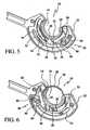
- Figures 3 through 10are cut away views demonstrating operation of the suturing apparatus.
- Figure 11is a perspective view showing a suturing body with a vacuum chamber in accordance with a preferred embodiment secured thereto.
- Figure 12shows an alternate vacuum chamber secured to the suturing body.
- Figures 13 and 14are top views of yet another vacuum chamber secured to the suturing body, wherein Figure 13 shows the vacuum chamber in its expanded configuration and Figure 14 shows the vacuum chamber in its low profile configuration.
- Figure 15is a cut away view of the suturing body showing a smooth friction camming member.
- Figure 16is an alternate embodiment of the suturing body showing a toothed friction camming member.
- Figure 17is a cut away view of yet another embodiment of the suturing body with a gear driven friction camming member.
- FIGS 18 and 19are cut away views of the suturing body showing alternate back-up mechanisms which may be utilized.
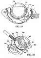
- Figures 20 , 21 and 22are various views of a suturing body including a cam pin set mechanism utilized in selectively opening the suture housing.
- Figures 23 and 24are bottom views of a suturing body showing a tear strip mechanism utilized in selectively opening the suture housing.
- Figures 25 and 26are bottom views of a suturing body showing yet another mechanism utilized in selectively opening the suture housing.
- Figures 27 and 28are bottom views of a suturing body showing a spreader plate mechanism utilized in selectively opening the suture housing.
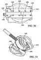
- Figures 29 , 30 and 31are various views of a suturing body showing an alternate mechanism for selectively opening the suture housing.
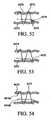
- Figure 32is a cut away view of the suturing body showing a needle position indicating mechanism.
- Figure 33is a cut away view of the suturing body showing an alternate needle position indicating mechanism.
- Figure 34is perspective view of a suturing body employing an alternate needle position indicating mechanism wherein an indicator pin is shown in its hidden position.
- Figure 35is a cross sectional view of the needle position indicating mechanism shown in Figure 34 with the indicator pin shown in its hidden position.
- Figure 36is perspective view of the suturing body shown in Figure 34 with the indicator pin in its exposed position.
- Figure 37is a cross sectional view of the needle position indicating mechanism shown in Figure 36 with the indicator pin in its exposed position.
- Figure 38is a detailed side, cut away view showing a colored needle utilized in needle position identification.
- Figure 39is a perspective view showing a visual indicator linked to various sensors for identifying needle position.
- Figures 40 , 41 , 41a , 42 , 42a and 43are various views showing an attachment mechanism for securing the present suturing apparatus to an endoscope.
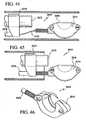
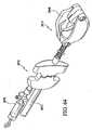
- Figures 44, 45 and 46show a guidewire introducer mechanism for use in conjunction with the present suturing apparatus.
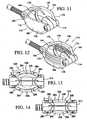
- Figures 47, 48 , 49 , 50 and 51disclose a detachable handle mechanism for utilization in conjunction with the present suturing apparatus.
- Figures 52 through 61disclose various techniques for suture lacing.
- Figure 62is a perspective view of a knotting element.
- Figure 63is a perspective view showing fusing of knotted sutures.
- Figures 64 , 65 , 66 , 67 and 68are perspective views showing various suction vacuum assist mechanisms.
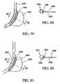
- Figure 69shows a suturing technique utilizing an adhesive/sealant.
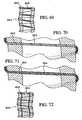
- Figures 70, 71 and 72show a perforated suture utilized in supplying adhesive/sealant to a suture line.
- Figures 73 through 82disclose a procedure whereby a stomach pouch is created through the application of an adhesive/sealant.
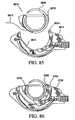
- Figures 83 and 84are perspective views of a suturing apparatus incorporating an imaging device within the suturing body.
- Figure 85is a cut away view of the suturing body showing a cartridge mechanism for utilization therewith.
- Figure 86is a cut away view of the suturing body showing a cartridge mechanism having a smaller needle.
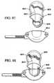
- Figures 87 and 88are side views showing a needle loading mechanism.
- Figures 89, 90 and 91disclose screw-based mechanisms for adjusting the size of the vacuum chamber and central opening.
- Figure 92is a cut away view showing a wire-based mechanism for adjusting the effective depth of the vacuum chamber and central opening.
- Figure 93is a top view showing a cinching line utilized in adjusting the effective size of the vacuum chamber and central opening.
- an endoscopic suturing apparatus 10 for the continuous application of a suture 12is disclosed.
- sutureas used throughout the body of the present application is intended to refer to a variety of flexible securing filaments whether they be made of natural filament, synthetic or polymeric filaments, or metallic wire filaments.
- the present suturing apparatusis particularly adapted for use in performing endoscopic gastric reduction procedures, those skilled in the art will certainly appreciate the apparatus may be used for a wide variety of applications. More particularly, the present suturing apparatus is shaped and dimensioned for insertion through a natural orifice of a patient, for example, transorally, and is, therefore, shaped and dimensioned for insertion through an orifice from approximately 3 mm to approximately 24 mm in diameter.
- the present suturing apparatusis particularly adapted for insertion through a patient's natural orifice
- the present suturing apparatusmay be shaped and dimensioned for laparoscopic insertion through a trocar, and is, therefore, shaped and dimensioned for insertion through an orifice from approximately 3 mm to approximately 18 mm in diameter.
- the suturing apparatus 10includes a suturing body 14 shaped and dimensioned for attachment to the distal end 16 of a commercially available endoscope, or other supporting structure, 18 in a manner permitting actuation thereof and the creation of a vacuum
- the suturing body 14is secured to the endoscope 18 using known attachment structures appreciated by those skilled in the art.
- the suturing body 14is composed of a first housing member 20 and a second housing member 22 secured together to create a suture housing 24 in which the functional components of the present apparatus 10 are housed for movement in accordance with the present invention.
- the suture housing 24includes an inner first track 26 in which a needle 28 is positioned for movement about a predetermined continuous circular path under the control of a drive assembly 30.
- the present suturing apparatusis disclosed in accordance with a preferred embodiment as providing for the translation of the needle about a continuous circular path, it is contemplated many of the concepts underlying the present invention may be applied in systems wherein the needle is merely moved along an arcuate path, and not necessarily along a continuous circular path.
- the drive assembly 30is supported within second and third tracks 32, 34 positioned about the inner first track 26.
- the drive assembly 30applies axial motion to cause movement of the needle 28 about its continuous circular path.
- the drive assembly 30is generally composed of a friction plate 36 statically mounted along the second track 32 and a friction camming member 38 that moves along the second track 32 while a pin 40 moves along the outer third track 34.
- a drive cable 42is coupled to the pin 40 for controlling actuation thereof in the manner described below in greater detail.
- the drive cable 42is actuated for movement of the drive assembly 30 by a handle (for example, as shown in Figures 47 to 51 ). Although a preferred handle is disclosed below, it is contemplated a variety of handle structures may be utilized in the actuation of the drive cable.
- the suturing body 14is substantially G-shaped with a central opening 44 in which tissue is positioned during suturing.
- the G-shape of the suturing body 14allows the needle 28 to move about a circular path during operation thereof and pass through tissue positioned with the central opening.
- the present endoscopic suturing apparatus 10is attached to a commercially available endoscope 18 byway of a clamp 17.
- the suturing apparatus 10may be secured to the endoscope 18 in a variety of ways.
- the suturing apparatus 10is oriented in a way that allows the user to maintain visibility of the needle 28 and operative field, as well as create a small cross section to aid in transoral insertion (when the suturing apparatus 10 is used in gastric surgical procedures).
- a vacuum chamber 46surrounds and/or otherwise contains the suturing body 14 of the present suture apparatus 10. This defines a cavity 48 in which the suturing body 14 sits.
- the vacuum chamber 46is coupled to the vacuum line 50, which is coupled in tandem to the endoscope 18, but not in the working channel of the endoscope 18, such that a vacuum is created within the cavity 48 defined by the vacuum chamber 46, as well as the central opening 44 of the suturing body 14. In this way, the application of the vacuum draws adjacent tissue into the central opening 44 of the suturing body 14.
- the present suturing apparatus 10is provided with a vacuum chamber 46 designed to enhance one's ability to draw tissue into a position for suturing.
- the vacuum chamber 46is shaped and dimensioned to facilitate pulling the tissue wall into the vacuum chamber 46, and particularly, the central opening 44 of the suturing body 14, under the control of the applied vacuum. Once drawn within the vacuum chamber 46 and the central opening 44, the tissue is held therein as the needle 28 is passed therethrough while the suturing body 14 throws stitches.
- the required vacuum chamber 46 sizeis based upon the thickness of the tissue being sutured. The vacuum necessary to pull the desired tissue thickness is proportionate to both the thickness of the tissue and the size of the vacuum chamber 46.
- the present vacuum chamber 46attempts to increase the size thereof to minimize the required vacuum for accomplishing the task, without making the vacuum chamber 46 too large for passage into the stomach.
- the ability of the present vacuum chamber 46 to achieve desired suction with vacuum pressure provided at a hospital or other medical facilityis especially important considering the magnitude of vacuum sources available at different hospitals, as well as within different surgical suites, varies greatly.
- the vacuum chamber 146is constructed from a resilient elastomer. It is cup-like in its configuration and generally includes an inner wall 170 and an outer wall 172.
- the inner wall 170 of the vacuum chamber 146is preferably provided with projections, for example, ribs and/or hooks, 174 (as shown in Figure 12 ) to further improve the ability of the vacuum chamber 146 to retain tissue drawn thereon under suction.
- projections 174provide grabbing surfaces for the tissue to be pinned against when the vacuum is applied to the vacuum chamber 146.
- the projections 174also increase the holding power of the vacuum thereby minimizing the amount of vacuum needed.
- the vacuum chamber 146is composed of first and second vacuum chamber members 176,178 secured to opposite sides of the suturing body 114 in a manner containing, or otherwise surrounding, the functional components of the suturing body 114.
- the first and second chamber members 176, 178are mirror images of each other and define a space surrounding the suturing body 114 for the creation of a vacuum.
- the first and second vacuum chamber members 176, 178define a cup-like space in which the suturing body 114 is positioned.
- Each of the first and second vacuum chamber members 176,178includes a semicircular upper edge 184 and a concave lower portion 186. As such, when the first and second vacuum chamber members 176,178 are secured along opposite sides of the suturing body 114, the cup-like space is defined about the suturing body 114.
- the cup-like spaceprovides a confined space in which the suction provided by the vacuum is constrained so as to securely and efficiently draw tissue into the central opening 144 of the suturing body 114.
- the first and second vacuum chamber members 176,178 of the vacuum chamber 146are manufactured from an elastomer, for example, urethane, adiprene or santoprene.
- the vacuum chamber 146is designed to permit expansion and contraction thereof.
- the provision of an expandable vacuum chamber 146maximizes chamber size to increase tissue inclusion during vacuum application, while permitting reduced vacuum chamber 146 size during insertion of the suturing apparatus 110. More particularly, the ability of the vacuum chamber 146 to expand and contract facilitates trans-oral passage of the suturing apparatus 110 while similarly optimizing vacuum chamber 146 size during tissue suction.
- the need for trans-oral passage of the suturing apparatus 110defines an ultimate limit on the dimensions of the suturing apparatus 110 and, therefore, the vacuum chamber 146 that can be introduced to capture tissue.
- the larger the vacuum chamber 146the larger the "bite" of tissue that can be captured in one throw of the suturing apparatus 110.
- the vacuum chamber 146is made out of an elastomer allowing it to be collapsed during insertion and then "spring" back to its original shape after it is fully inserted.
- the vacuum chamber 246is composed of a first vacuum chamber member 276 and a second vacuum chamber member 278.
- the first and second vacuum chamber members 276, 278are mirror images of each other, and each includes a semi-circular upper section 284 and a concave lower section 286.
- the first and second vacuum chamber members 276, 278are coupled to opposite sides of the suturing body 214 to form the present vacuum chamber 246, which can similarly include the ribs and/or hooks discussed above with regard to the prior embodiment.
- the first and second vacuum chamber members 276, 278are constructed of a semi-rigid material and, therefore, respectively include living hinges 280 permitting expansion and contraction thereof.
- the living hinges 280are positioned at predefined bending points of the first and second vacuum chamber members 276, 278 in a manner optimizing folding thereof.
- the living hinges 280permits controlled expansion and contraction of the vacuum chamber 246 as the first and second vacuum chamber members 276, 278 are moved relative to each other. One is, therefore, able to pass a vacuum chamber 246 that is ultimately, when used, larger than the trans-oral space through which it is passed.
- a vacuum chamber and central openingadapted to accommodate any type of tissue, any thickness of tissue and be able to allow the user to adjust the bite size (that is, the extent of tissue through which the suture is thrown).
- various embodiments for the adjustment of the effective vacuum chamber and central opening sizehave been developed and are disclosed herein. These embodiments also allow for longitudinal and lateral adjustment of the vacuum chamber, as well as depth adjustment of the central opening and vacuum chamber, to allow for use with different tissue thicknesses, different tissue types and variable tissue bites per suture throw.
- the surgeonis allowed to readily adjust the effective vacuum chamber/central opening depth, width and/or length to allow for adjustment of the depth of the tissue bite, which controls the depth of the needle path through the tissue (i.e., full thickness or partial thickness).
- the ability for adjustmentalso allows the same suturing apparatus to be used for multiple tissue types and thicknesses. While limiting the maximum amount of tissue that may be drawn into the vacuum chamber and central opening, the present techniques may also be applied to ensure that a predetermined and controlled amount of tissue is drawn into the vacuum chamber and the central opening.
- adjustmentis accomplished by the provision of adjusting screws 3970 in the base 3972 of the vacuum chamber 3946.
- the screws 3970respectively allow for longitudinal or lateral adjustment of the vacuum chamber 3946 by adjusting a screw 3970 in the base 3972 of the vacuum chamber 3946 that expands or contracts the vacuum chamber 3946 in a desired direction.
- a wire 4070is used to raise the effective base of the vacuum chamber 4046 and the central opening 4044 controlling the effective depth of the vacuum chamber 4046 and the central opening 4044.
- This wire 4070is a buckled spacing wire that can be further buckled or allowed to straighten, effectively reducing the depth to which the tissue can enter the cavity defined by the central opening 4044 and the vacuum chamber 4046.
- the spring wire 4070thereby prevents deep entrance of tissue (that is, entrance beyond the barrier created by the spring wire 4070) into the central opening 4044.
- the slack in the wire 4070is controlled via a screw member 4072 found within the suturing body 4014 for actuation of the wire 4070.
- a cinching cable 4170is used to adjust the effective length of the vacuum chamber 4148.
- a cinching cable 4170is threaded about the outer perimeter of the vacuum chamber 4146, with the free ends 4172, 4174 thereof exiting at the proximal end of the vacuum chamber 4146.
- the free ends 4172, 4174may be tensioned to shorten the vacuum chamber 4146 length, and similarly released when it is desired to increase the length of the vacuum chamber 4146 by allowing the walls thereof to expand to their unbiased position.
- the housing 24contains the needle 28 used in the application of a suture 12 to the tissue drawn within the central opening 44.
- the suture 12is secured to the proximal end, that is, the blunt end, of the needle 28 and is drawn through the tissue as the needle 28 is actuated.
- the needle 28is curved to rotate about a predetermined continuous circular path and extends along an arc of 240 degrees creating an opening of 120 degrees.
- the openingmay be varied; for example, it has been contemplated to use a needle offering an opening of 140 degrees.
- the needle 28includes an interior surface 52 along the inner surface of the arc defined by the needle 28 and an exterior surface 54 along the outer surface of the arc defined by the needle 28.
- a series of notches 56are cut into the exterior surface 54 of the needle 28.
- the notches 56are shaped and dimensioned for use by the drive assembly 30 in grabbing, driving and releasing the needle 28.
- the needlemay be formed without notches such that the drive assembly merely grips the substantially smooth exterior surface of the needle to drive it forward.
- the drive cable 42(shown in Figure 3 ) is rigidly attached to the pin 40. As is described below in greater detail, the drive cable 42, pin 40 and friction camming member 38 are extended and retracted to engage and disengage the needle 28 for movement thereof about its circular path.
- the drive cable 42is flexible enough to curve in the housing 24 and flex along with the endoscope 18, but is rigid enough to be compressed to drive the friction camming member 38 into its initial drive stage (see Figure 4 ).
- the friction camming member 38is composed of an arcuate engagement member 58 and a camming member 60 working in conjunction with the pin 40 to control the position of the engagement member 58 for selective engagement with the needle 28.
- the engagement member 58is constructed with internal notches 62 shaped and dimensioned for engaging the needle 28 to drive it in a clockwise direction, but permit free movement thereof as the friction camming member 38, that is, both the engagement member 58 and the camming member 60, is moved in a counter-clockwise direction toward the initial drive stage.
- the engagement member 58 of the friction camming member 38is designed to translate in the housing 24 both radially towards and away from the needle 28, as well as translate arcuately clockwise and counterclockwise about the arc defined by the housing 24. This is achieved through the camming action offered by the interaction between the camming member 60, the pin 40 and the engagement member 58.
- the camming member 60is rigidly coupled to the engagement member 58 such that the engagement member 58 is moved into and out of engagement with the needle 28 as the radial position of the camming member 60 is altered based upon its interaction with the pin 40.
- a spring elementmay be employed to force the friction camming member 38 against the needle 28.
- the pin 40slides within a slot 64 formed in the camming member 60 forcing the engagement member 58 and camming member 60 to move counterclockwise as well as outwardly from the needle 28.
- the friction plate 36aids in forcing the engagement member 58 outwardly from the needle 28 as the friction camming member 38 is moved in this counter-clockwise direction.
- the drive assembly 30is capable of driving the needle 28 about its circular path in a highly controlled and efficient manner.
- the functionality of the present drive assembly 330is enhanced by the provision of the friction camming member 338, which drives the needle 328 when pulling the needle 328 along its path through frictional means.
- the contact surface of the frictional interface 358 of the friction camming member 338is manufactured to enhance its frictional relationship with the needle 328 so as to smoothly and reliably move the needle 328.
- the interaction between the friction camming member 338 and the needle 328is enhanced by the provision of a leaf spring 370.
- the leaf spring 370extends within the suture housing 324 of the suturing apparatus 310 and is oriented to contact the friction camming member 338 during actuation of the needle 328 for forcing the friction camming member 338 into contact with the needle 328.
- the leaf spring 370is a cantilever mounted spring member mounted proximally of the friction camming member 338. As the friction camming member 338 is forced distally, the leaf spring 370 increases the engagement forces radially the farther the friction camming member 338 is displaced.
- a spring structureis disclosed and other spring structures could be employed.
- the smooth friction camming member 338 discussed abovemay be replaced with a toothed friction camming member 438.
- the contact surface of the frictional interface 458 of the friction camming member 438is provided with teeth 472 shaped and dimensioned to engage similarly shaped teeth 474 formed along the exterior surface of needle 428.
- the teeth 472 along the frictional interface 458 of the friction camming member 438engage teeth 474 cut into the needle 428 and drag the needle 428 along its drive path when pulled.
- the interaction between the friction camming member 438 and the needle 428is enhanced by the provision of a leaf spring 470.
- the leaf spring 470extends within the suture housing 424 of the suturing apparatus 410 and is oriented to contact the friction camming member 438 during actuation of the needle 428 for forcing the friction camming member 438 into contact with the needle 428.
- the motion of the friction camming member 538(whether it be a smooth friction camming member 338 as shown in Figure 15 or a toothed friction camming member 438 as shown in Figure 16 ) used in driving the needle 528 can also be achieved through the use of a sprocket gear 570 engaging with teeth 572 on the back side 574 of the friction camming member 538 driving the needle 528 through the same motions the linear pull system created.
- Such a gearing arrangementprovides for the translation of rotary motion along the drive cable 582, and about a first axis substantially aligned with the longitudinal axis of the suturing apparatus 510 extending through the suturing apparatus 510, into rotary motion of the needle 528 about an arcuate path having a central axis substantially perpendicular to the longitudinal axis of the suturing apparatus 510.
- the sprocket gear 570is rotated by a rotary cable drive system 576 linked to a rotary member in the handle (not shown) which would replace the linear pull system.
- the rotary cable motion(rotating about the longitudinal axis of the device shaft) is converted to rotary motion (rotating perpendicular to the longitudinal axis of the device shaft) to drive the needle 528 directly along its circular path or to drive the toothed friction camming member 538 in its path.
- the drive cable 582is designed for rotation about an axis substantially parallel to the longitudinal axis of the apparatus 510.
- the distal end 584 of the drive cable 582is provide with spur gear 586 which is linked to a similar spur gear 588 mounted between the spur gear 586 at the distal end 584 of the drive cable 582 and a geared contact surface 574 of the friction camming member 538.
- rotation of the drive cable 582causes the spur gear 586 to rotate, which in turns translates into motion of the friction camming member 538. Movement of the friction camming member 538 then causes the needle 528 to move in a desired arcuate path.
- friction camming member 538engages and disengages the needle 528 in a manner similar to the embodiment described above, movement of the needle 528 is achieved by alternately reversing the rotation of the rotary cable system. Forward rotation cams the friction camming member 538 into engagement and drives the friction camming member 538 counter-clockwise in a manner driving the needle 528. Reverse rotation of the drive cable 582 disengages the friction camming member 538 from the needle 528 and rotates the friction camming member 538 clockwise resetting it for the next driving motion.
- the drive mechanism employedprovides a rotary needle drive system for suture pass-through capable of multiple tissue pass-through during a single device insertion. As discussed above, this is accomplished by a friction camming member that advances the needle by means of a toothed engagement or a frictional coupling, and provides for needle advancement permitting variation in the size of both the needle and suture used.
- Two anti-backup structuresare disclosed with reference to Figures 18 and 19 . These anti-backup structures control needle movement so the needle is only allowed to pass in one direction. This prevents the needle from backing out between actuating strokes of the fricton camming member as it moves between its end (or limit) of stroke position as shown in Figure 6 and its initial drive position as shown in Figure 8 . More particularly, the needle of the present suturing apparatus is designed to move in a predetermined first direction about an arcuate path, and movement in an opposite second direction is undesired. As such, the present anti-backup structures prevent movement of the needle in the second direction while permitting free movement of the needle in the first direction.
- a frictional anti-backup device 670is secured along the forward end of the needle 628 path for contact with the needle 628 in a manner preventing undesired back-up thereof.
- the frictional anti-backup device 670is a lever arm 672 including a first end 674 and second end 676.
- the first end 674 of the lever arm 672is pivotally secured to the suturing body 614 of the suturing apparatus 610.
- the second end 676 of lever arm 672extends toward, and into contact with, the contact surface of the needle 628.
- the lever arm 672is oriented such that when the needle 628 is moved in a counter-clockwise direction as viewed in Figure 18 , the lever arm 672 slides over the exterior surface of the needle 628 permitting the needle 628 to freely rotate.
- the second end 676 of the lever arm 672frictionally engages the exterior surface of the needle 628 in a manner stopping clockwise rotation thereof.
- the lever arm 672is biased to maintain engagement with the exterior surface of the needle 628 whether the needle is rotated in a clockwise direction or a counter-clockwise direction.
- the suturing body 714is provided with an integral spring biased latch 770 shaped and dimensioned to fit within recesses 772 formed in the exterior surface of the needle 728.
- the latch 770 and the recesses 772are shaped and dimensioned to permit substantially free rotation of the needle 728 in one direction while preventing rotation of the needle 728 in the opposite direction.
- a surgical suturing apparatusincludes a suture housing and a needle mounted within the suture housing for movement about an arcuate path.
- the suturing apparatusalso includes a drive assembly operably associated with the needle for controlling movement of the needle with a suture secured thereto about the arcuate path in a manner facilitating application of the suture to tissue.
- the suture housinghas an open position and a closed position, and the needle can be removed from the suture housing when in the open position.
- the various embodimentsprovide a user a controlled opening mechanism that allows the suture housing to be selectively opened should the needle fail to be able to advance and the suturing apparatus needs to be extracted. As will be described below in greater detail, this is achieved by employing either a spring biased, hinged clamshell suturing body opening when a crushable coupling mechanism is actuated, a removable pin/cable mechanism that holds the two halves of the suturing body together or an openable suture deployment system that can be re-closed for extraction from the body.
- the suturing body 814is composed of a first housing member 820 and second housing member 822 making up the suture housing 824.
- a cam pin set 870locks the first housing member 820 and the second housing member 822 together, with, however, the ability to remove the cam pin set 870 from the second housing member 822 when it is desired to separate the first and second housing members 820, 822 for removal of a jammed needle 828.
- first and second housing members 820, 822are hinged 872 along one end thereof, and the cam pin set 870 is positioned in a manner opposite the hinge 872 so the first and second housing members 820, 822 are securely held together.
- the cam pin set 870is removed, or otherwise removed from its locking position with a second housing member 822, the first and second housing members 820, 822 are free to move apart pivoting about the hinge 872. Opening of the suturing housing 824 is further facilitated by the inclusion of a spring 874 in the hinge 872 for encouraging opening of the suturing housing 824 upon removal of the cam pin set 870.
- Actuation of the cam pin set 870is achieved via the use of a release member 876 that interacts to permit controlled locking and release of the cam pin set 870.
- the release member 876includes a series of interference members 878 which interact with the heads 880 of the cam pin set 870 to retain them within recesses 882 formed in the second housing member 822 (see Figure 21 ).
- the release member 876is shifted, for example, via a cable 884 extending for actuation by a user, to move the interference member 878 and allow the cam pin set 870 to move from within the second housing member 822 (see Figure 22 ).
- a tear strip 970is disclosed.
- the suturing body 914is composed of a first housing member 920 and second housing member 922 making up the suture housing 924.
- the first and second housing members 920, 922are hinged 972 along one end thereof, with a spring 974 biasing the first and second housing members 920, 922 to an open orientation.
- the tear strip 970is positioned through the centerline of the first and second housing members 920, 922.
- the tear strip 970is secured to the first and second housing members 920, 922 either through adhesive or other mechanical frangible, plastic coupling features.
- the tear strip 970When pulled, the tear strip 970 "tears" the center out from between the first and second housing members 920, 922 allowing the suturing apparatus 910 to fall open.
- the tear strip 970may be a straight adhesive or molded strip, or the tear strip 970 may include a camming feature (as discussed below) as part of the distal most end further spreading open the halves as it is removed.
- FIG. 25A further embodiment is disclosed with reference to Figures 25 and 26 .
- This embodimentemploys a pull cable 1070 to facilitate selective opening of the suturing body 1014 for release of a jammed needle therefrom
- the suturing body 1014is composed of a first housing member 1020 and second housing member 1022 making up a suture housing 1024.
- the first and second housing members 1020,1022are hinged 1072 along one end thereof.
- the first and second housing members 1020,1022are further provided with lacing loops 1074 along the open end thereof.
- the lacing loops 1074are shaped and dimensioned to permit the placement of a pull cable 1070 therethrough in a manner which holds the first and second housing members 1020, 1022 together.
- the pull cable 1070is laced through the lacing loops 1074 alternately positioned on the first and second housing members 1020, 1022 much like the hinge of a door.
- the pull cable 1070is present around the perimeter of the first and second housing members 1020, 1022, the first and second housing members 1020, 1022 are held together and the needle 1028 is retained therein.
- the pull cable 1070is pulled withdrawing it from the lacing loops 1074 and releasing the first and second housing members 1020, 1022 from each other. With the first and second housing members 1020, 1022 released, the spring biased hinge 1072 draws the first and second housing members 1020, 1022 apart by pivoting them along the hinge 1072.
- a spreader plate 1170 embodimentis disclosed with reference to Figures 27 and 28 .
- the center connection member 1172not only joins and releases the two housing members 1120, 1122, but has a camming member 1174 on the distal end of the center connection member 1172 that as it is pulled through the system actually cams the first and second housing members 1120,1122 apart not just allowing them to freely fall apart.
- the suturing body 1114includes a first housing member 1120 and a second housing member 1122 making up the suture housing 1124.
- the first and second housing members 1120,1122are hinged 1176 along one end thereof, with a spring 1178 biasing the first and second housing members 1120, 1122 to an open orientation.
- the central connection member 1172is positioned through the centerline of the first and second housing members 1120,1122.
- the central connection member 1172is secured to the first and second housing members 1120, 1122 through a member that is rigid enough to prevent inadvertent deployment of the system but can be broken or disengaged from the distal end of the suture housing 1124. When pulled, the central connection member 1172 releases the first and second housing member 1120,1122 allowing the suture housing 1124 to fall open.
- the opening of the suturing body 1114 upon removal of the central connection member 1172is facilitated by including a camming member 1174 at the distal end 1180 of the central connection member 1172.
- the camming member 1174is positioned and shaped such that it extends between the first and second housing members 1120,1122 in a manner pushing the first and second housing members 1120,1122 apart for removal of the needle 1128 or to provide other access to the internal structure of the suturing body 1114.
- the embodimentemploys a series of crushable interlocking clamps 1270 in the selective opening of the suturing body 1214.
- the Interlocking clamps 1270hold the first and second housing members 1220, 1222 together during normal function.
- a cable 1272 secured to the interlocking clamps 1270is pulled, the interlocking clamps 1270 are crushed, unlocking the first and second housing members 1220, 1222 and allowing them to pivot open under the control of the spring biased hinge 1274.
- each of these embodimentsis provided with a housing outer profile, shaped and dimensioned to permit limited closing of the suturing body as it is withdrawn from the stomach.
- the outer profileis rounded with a convex profile designed such that the first and second housing member are at least partially forced together when the suturing device is withdrawn through a trans-oral tube.
- first and second housing membersmay be desirable to hinge the first and second housing members along their proximal ends (see Figures 27 and 28 ). Either of the various release mechanism may be used in accordance with this embodiment. However, by positioning the hinge at the proximal end thereof the first and second housing members are directly connected to the shaft allowing them to be easily re-closed during extraction rather than having numerous loose parts free to move and fall wherever.
- the present suturing apparatusis provided with a variety of indicators for both physical and visual identification of the procedure being performed.
- the present endoscopic suturing deviceincludes means for identifying the position of the needle along its path both locally in the surgical field and externally on the actuation mechanism.
- the endoscopic suturing deviceincludes a secondary mechanism designed to stop the needle at the end of one full actuation to indicate to the user that it is the proper time in the sequence to re-position the device for subsequent actuations.
- the surgical suturing apparatusincludes a suture housing and a needle mounted within the suture housing for movement about an arcuate path.
- a drive assemblyoperably associated with the needle for controlling movement of the needle with a suture secured thereto about the arcuate path in a manner facilitating application of the suture to tissue.
- a mechanismis provided for determining the position of at least one of the distal end of the needle and the proximal end of the needle at all points along the arcuate path about which the needle moves.
- the endoscopic suturing device 1610includes a spring ball lock 1670 shaped and dimensioned to provide a physical indication of the needle 1628 position.
- a small ball bearing 1672is spring 1674 biased into the path of the oncoming needle 1628 to stop its motion at the end of its travel
- the ball bearing 1672is mounted within the suturing body 1614 for access to and contact with the exterior surface of the needle 1628.
- the ball bearing 1672is spring 1674 biased toward the exterior surface of the needle 1628.
- the needle 1628is provided with a recess 1676 along its exterior surface (preferably adjacent the tip of the needle, although multiple recesses may be employed at various locations along the length of the needle to provide physical indications of needle position).
- the recess 1676is shaped and dimensioned to permit the ball bearing 1672 to seat therein when the needle recess 1676 comes into alignment with the ball bearing 1672 providing the user with tactile feedback of the needle positioned 1628.
- the ball bearing 1672is positioned adjacent the entry point for the needle 1628 as it begins its throw loop and the recess 1676 of the needle 1628 is formed therealong at a position such that the operator is provided with additional tactile feedback that a complete needle loop is achieved.
- the ball bearingmay be used in combination with a camming mechanism to move it out of the path for the next stroke to occur or it can be used at a restricting force that only applies feedback to the user that the end of a stroke has been achieved, but can be overcome by the user though the application of more force.
- a spring ratchet pawl lock 1770is oriented to interfere with movement of the needle 1728 for identifying needle 1728 position and the completion of a needle loop. More particularly, a pawl lock lever arm 1772 is secured along the forward end of the needle path for contact with the needle 1728 in a manner providing a physical indication as to the position of the needle 1728. The pawl lock lever arm 1772 is secured along the forward end of the needle path for contact with the needle 1728 in a manner providing a physical indication. The pawl lock lever arm 1772 includes a first end 1774 and second end 1776.
- the first end 1774 of the lever arm 1772is pivotally secured to the suturing body 1714 of the suturing device 1710.
- the second end 1776 of lever arm 1772extends toward and into contact with the exterior surface of the needle 1728.
- the lever arm 1772is oriented such that when the needle 1728 is moved in a counter-clockwise direction, the lever arm 1772 slides over the exterior surface of the needle 1728.
- the exterior surface of the needle 1728is provided with a recess 1778 along its exterior surface.
- the recess 1778is shaped and dimensioned to permit the second end 1776 of the lever arm 1772 to seat therein when the needle recess 1778 comes into alignment with the second end 1776 of the lever arm 1772.
- the lever arm 1772is positioned adjacent the entry point for the needle 1728 as it begins its throw loop and the recess 1778 of the needle 1728 is formed therealong at a position such that the operator is provided with a tactile feedback that a complete needle loop is achieved.
- the suturing apparatusincludes a pop-out indicator pin 1870.
- the pin 1870is shaped and dimensioned to pop out the side of the suturing body 1814 when the needle 1828 is in its advanced position giving the surgeon visible feedback as to the needle 1828 position within the surgical site of the endoscope. Once the needle 1828 is fully advanced, the pin 1870 is spring biased to the hidden or in position indicating the suturing apparatus 1810 is ready for repositioning (see Figures 34 and 35 ). Visualization thereof is provided by coloring the exposed portion 1871 of the pin 1870 in a distinctive color to allow ready identification that the needle 1828 is positioned in a desired orientation.
- the pin 1870is spring biased within an aperture 1872 formed in the wall of the suturing body 1814.
- the pin 1870is biased to a hidden position and includes a first end 1876 and a second end 1878.
- the first end 1876is positioned for contact with the needle 1828 as it moves along its arcuate path, while the second end 1878 is positioned adjacent the outer surface of the aperture 1872 for movement between a hidden position and an exposed position.
- the second end 1878 of the pin 1870is colored in a distinctive manner allowing ready visualization thereof.
- Movement of the pin 1870is facilitated by the movement of the needle 1828 into contact with the first end 1876 of the pin 1870.
- the first end 1876 of the pin 1870is seated within the path of the needle 1828, although it is shaped and dimensioned to readily move once the needle 1828 moves into contact therewith (without unduly interfering with the movement of the needle as it makes its arcuate path).
- the needle 1928is colored to provide ready visualization thereof. More particularly, the needle 1928 is made with contrasting color to the surgical field to improve the visibility of the surgeon to identify where the needle 1928 is currently positioned. In accordance with a preferred embodiment, the tip 1970 is colored with the contrasting color to provide a ready identification the needle is exiting the suturing body.
- the needle 2028 positionis calibrated with an indicator 2070 secured at the handle of the suturing apparatus 2010. It is contemplated the indicator 2070 might be several hemispherical patterned lights, a dial indicator or other circular path indicator.
- the suturing body 2014is provided with one or multiple Hall effect sensors 2074 working in conjunction with the needle 2028 to provide the operator with an indication of the needle 2028 position. As the steel or magnetized steel needle 2028 passes adjacent the three sensors 2074 shown in Figure 39 the system lights up the appropriate needle position indicator lights 2070 on handle 2072.
- Hall effect sensorsare disclosed, other electronic means known to those skilled in the art could be used. For example, the sensors could be mechanical spring biased switches, or even extremely low voltage contact or inductance switches that make contact through needle itself making contact with both side of the switches (one placed on either side of the needle track).
- Improved functionality of the present suturing apparatusis achieved by the provision of a mechanical attachment mechanism specifically adapted for attaching the vacuum chamber and suturing body to the end of the endoscope, allowing for rotational positioning of the endoscopic suturing device with respect to the endoscope.
- the various embodiments described belowprovide for a mechanical attachment mechanism that attaches the vacuum chamber and suturing body at the end of the endoscope, allowing for flexible positioning of the vacuum chamber and suturing body away from the endoscope to increase visibility of the pocket.
- the mechanical attachment mechanismincludes a flexible connection arm that collapses against the endoscope during insertion for a low profile insertion, but then springs away from the endoscope once in the body to improve visibility of the vacuum chamber and suturing body for positioning and suture deployment.
- the mechanical attachment mechanismattaches the vacuum chamber and suturing body to the end of the endoscope through the use of a detachable mechanism that can be removed and passed into a body cavity prior to the introduction of the endoscope, or for interchanging the suturing apparatus with another suturing body or even another endoscopic device.
- a detachable mechanismthat can be removed and passed into a body cavity prior to the introduction of the endoscope, or for interchanging the suturing apparatus with another suturing body or even another endoscopic device.
- the mechanismsprovide for a unique method for access to a body cavity through either a natural orifice or a surgical initiated orifice, in particular, for inserting a suturing apparatus, or other surgical instrument, through a body orifice.
- the instrumenthas a low profile orientation and a deployed orientation which is larger than the size of the body orifice through which it is to be inserted.
- the methodis achieved by coupling the instrument to an endoscope and placing the instrument in its low profile orientation, inserting the endoscope and the instrument through a natural orifice to a target position within a body while the instrument is in its low profile orientation, and actuating the instrument to it is deployed orientation. Finally, the instrument is returned to its low profile orientation and withdrawn from the body through the natural orifice.
- a scope attachment ring 2170is secured about the distal end 2172 of the endoscope 2174 to which the present suturing apparatus 2110 is to be mounted.
- the attachment ring 2170generally includes a ring body 2176 having parallel apertures 2178, 2180 respectively shaped for the receipt of the endoscope 2174 and the support shaft 2182 of the present suturing apparatus 2110 to which the suturing body 2114 and vacuum chamber 2146 are attached.
- the first aperture 2178is shaped for frictional engagement with the outer surface of the endoscope 2174 in a manner preventing rotation of the attachment ring 2170 relative to the endoscope 2174.
- the second aperture 2180is shaped and dimensioned for receiving the shaft 2182 of the suturing apparatus 2110, and in accordance with a preferred embodiment thereof, the second aperture 2180 is slightly larger than the shaft 2182 of the suturing apparatus 2110. In this way, the suturing apparatus 2110 may be rotated relative to the endoscope 2174 for improved access to tissue. Positioning of the suturing apparatus 2110 relative to the attachment ring 2170 is achieved by positioning abutment members 2184, 2186 along the shaft 2182 of the suturing apparatus 2110 on opposite sides of the attachment ring 2170. These members 2184, 2186 can be coupled to the shaft 2182 via screw threads during manufacturing, pressed into place during manufacturing or be molded as part of the attachment ring itself. In this way, the suturing apparatus 2110 may be freely rotated relative to the endoscope 2174 while the suturing apparatus 2110 is substantiallyprevented from longitudinal movement relative thereto.
- an endoscope attachment ring 2270 similar to that described aboveis secured about the distal end 2272 of the endoscope 2274 to which the present suturing apparatus 2210 is to be mounted.
- the attachment ring 2270generally includes a ring body 2276 having parallel apertures 2278, 2280 respectively shaped for the receipt of the endoscope 2274 and the present suturing apparatus shaft 2282.
- the aperture 2278is shaped for frictional engagement with the outer surface of the endoscope 2274 in a manner preventing rotation of the attachment ring 2270 relative to the endoscope 2274.
- the second aperture 2280 receiving the shaft 2282 of the suturing apparatus 2210is approximately the same size as the shaft 2282 of the suturing apparatus 2210. In this way, the suturing apparatus 2210 is prevented from rotating relative to the endoscope 2274 allowing for the elastic deployment off the axis of the endoscope 2274 to permit better visualization.
- Positioning of the suturing apparatus 2210 relative to the attachment ring 2270is achieved by positioning abutment members 2284, 2286 along the shaft 2282 of the suturing apparatus 2210 on opposite sides of the attachment ring 2270.
- the fit between the endoscope attachment ring and the elastic armcould be a loose fit as discussed above with regard to the embodiment shown in Figure 40 permitting it to be freely rotated relative to the endoscope while the endoscopic suturing device is substantially prevented from longitudinal movement relative thereto.
- Improved access of the suturing apparatusis further facilitated by manufacturing the shaft 2282 distal from the second aperture 2280 of the attachment ring 2270 from a flexible material that is biased to a position removed from the endoscope 2274.
- the suturing apparatus 2210maybe held close to the endoscope 2274 during insertion, reducing the profile of the structure being inserted trans-orally, while allowing for movement of the suturing apparatus 2210 away from the endoscope 2274 when the suturing apparatus 2210 reaches its desired location.
- the portion of the shaft 2282a providing for flexing of the suturing body 2214 away from the endoscope 2274is an elastomer lever arm designed to move the suturing apparatus 2210 off axis from the endoscope 2274 in a manner improving visualization of the suturing apparatus 2210 and its usage while still allowing it to deflect against the endoscope during insertion and extraction, reducing its overall profile during these activities.
- the attachment ring 2270amay be constructed with a connection member 2283a extending distally from second aperture 2280a.
- the connection member 2283ais an elastomer lever arm designed to move the suturing apparatus 2210a, with the shaft 2282a thereof extending through the connection member 2283a off axis from the endoscope 2274a in a manner improving visualization of the suturing apparatus 2210 and its usage while still allowing it to deflect against the endoscope 2274a during insertion and extraction, reducing its overall profile during these activities.
- connection member 2283ais shaped and dimensioned to fit about the shaft 2282a of the suturing apparatus 2210a.
- the connection member 2283ais constructed of a resilient material and is biased to a position removed from the endoscope 2274a. In this way, the connection member 2283a with the shaft 2282a of the suturing apparatus 2210 extending therethrough may be held close to the endoscope 2274a during insertion, reducing the profile of the structure being inserted trans-orally. However, once the suturing body 2214a is positioned within the body cavity, the connection member 2283a is released, allowing it to extend away from the endoscope 2274a.
- the shaft 2282a of the suturing apparatus 2210is positioned within the connection member 2283a, the shaft 2282a and the suturing body 2214a are moved away from the endoscope 2274a as the connection member 2283a moves away from the endoscope 2274a.
- a guidewire introducer 2470 for a suturing apparatus 2410may be employed.
- a detachable vacuum chamber 2446 and suturing body 2414detailed above.
- the distal end components, that is, the vacuum chamber 2446 and the suturing body 2414are passed, for example, through the oral cavity in advance of the endoscope 2472 and subsequently attached to the endoscope attachment ring 2474 via a guide wire 2470 which is pulled through a support shaft 2476 in a manner drawing the suturing body 2414 and vacuum chamber 2446 onto the support shaft 2476.
- the endoscope 2472itself can be used to advance the detached vacuum chamber 2446 and a suturing body 2414 down the oral cavity.
- the pre-positioned guide wire 2470 within the working channel of the endoscope 2472is terminated at its distal end 2471 by connection to the vacuum chamber 2446 and suturing body 2414.
- the vacuum chamber 2446 and suturing body 2414are pulled back into attachment to the distal end of the endoscope 2472 and onto a support shaft 2476 by pulling the suturing body 2414 and vacuum chamber 2446 into engagement with the endoscope 2472 through the action of the guidewire 2470 to which the vacuum chamber 2446 and suturing body 2414 are connected.
- Thisallows for use of a vacuum chamber 2446 and suturing body 2414 that are laterally and thickness wise larger than could be passed in fixed attachment to the endoscope during insertion.
- the vacuum chambercan be interchangeable used with non-vacuum equipment that looks similar or identical to the vacuum version, but does not utilize the vacuum to position the tissue and merely relies upon placing the chamber adjacent to the tissue to be sutured. This drastically reduces the bite size, but also reduces the possible trauma to the tissue that vacuuming the tissue into the pocket may cause.
- a quick handle disconnectis also contemplated and is shown with reference to Figures 47,48 , 49 , 50 and 51 .
- This featuremay be used in combination with or separately from the guidewire introducer as described above.
- this embodimentemploys a suture housing 2524, a needle 2528 mounted within the suture housing 2524 for movement about an arcuate path, a drive assembly operably associated with the needle 2528 for controlling movement of the needle 2528 with a suture secured thereto about the arcuate path in a manner facilitating application of the suture to tissue, a handle 2570, an elongated flexible member, for example, a drive cable 2542 having a distal end attached to the suture housing 2524 and a proximal end attached to the handle 2570, and a mechanism for releasing and reattaching the handle 2570 to the flexible member 2542.
- a quick handle disconnectfacilitates distal detachment and pre-passing of the suturing apparatus 2510 through the selective attachment and detachment of the handle 2570 from the flexible drive cable 2542 to which the suturing body 2514 and vacuum chamber 2546 are connected.
- the drive cable 2542may function much like the guidewire previously discussed in allowing one to pass the suturing body 2514 and the vacuum chamber 2546 into position prior to complete assembly.
- This improvementallows one to pre-pass the suturing apparatus 2510 from the distal end of the endoscope in manner reducing the required profile because the suturing apparatus 2510 is positioned distal of the endoscope during passage thereof rather than passing the suturing apparatus 2510 from the proximal end of the endoscope in a manner increasing the required passageway since the profile must accommodate both.
- the handle 2570is composed of a handle body 2574 in which the drive cable 2542 is releasably secured for actuation.
- the handle body 2574includes a central passageway 2578 in which the drive cable 2542 is stored and mounted.
- the handle body 2574is composed of a central grip 2580 and a slide member 2581 that moves relative to the central grip 2580 in a manner discussed below in greater detail.
- the central passageway 2578includes a first open end 2582 and a second closed end 2584. Adjacent the second closed end 2584 is a spring loaded trigger lock 2586 secured to the central grip 2580.
- the trigger lock 2586is shaped and dimensioned to engage a protrusion 2594 (for example, a bullet nose tip) along the proximal tip 2588 of the drive cable 2542.
- a protrusion 2594for example, a bullet nose tip
- the proximal tip 2588 of the drive cable 2542is mounted within a recess 2590 in the proximal end 2592 of the passageway 2578 and within the central grip 2580 (for centering thereof), and the trigger lock 2586 is moved downward into engagement with the protrusion 2594 for maintaining the drive cable 2576 within the handle body 2574.
- Retention of the drive cable 2542 within the handle body 2574is further facilitated by the inclusion of a locking slide 2596 along the slide member 2581.
- the locking slide 2596frictionally interacts with a collar 2598 formed on drive cable 2542 for retention of the handle body 2574 thereon.
- the distal end of the drive cable 2542is inserted within the passageway 2578 formed in the slide member 2581.
- the drive cable 2542is inserted to such a point that the collar 2598 of the drive cable 2576 is aligned with openings 2583 formed along the slide member 2581.
- the locking slide 2596is slid along the slide member 2581 and is moved over the collar 2598 into engagement therewith.
- the drive cable 2542is, at this point, secured to the slide member 2581.
- the slide member 2581is then moved proximally relative to the central grip 2580 until the proximal end 2588 of the drive cable 2542 is seated within the recess 2590 formed in the central grip 2580.
- the trigger lock 2586is then spring actuated to engage the protrusion 2594 at the proximal tip 2588 of the drive cable 2542 for securing it to the central grip 2580 and the handle body 2574.
- the trigger lock 2586is rotated forward to permit release of the protrusion 2594 from within the recess 2590 of the central grip 2580.
- the present handle 2570allows for actuation of the drive cable 2542 in a manner operating the present suturing apparatus 2510.
- relative movement of the central grip 2580 and the slide member 2581 while the drive cable 2542 is seated within the central grip 2580causes actuation thereof permitting the drive assembly to function in the manner described above.
- the releasable connectioncould similar be applied in the selective connection of the suturing body to the shaft connecting the suturing body to the handle. In this way, one could selectively connect the suturing body to the shaft once the suturing body is positioned within the body cavity and ready for use in the application of a suture to tissue.
- the vacuum pressure available in different operating room suitesvaries greatly from location to location. Improvements to the vacuum chamber minimizing the necessary vacuum required have been discussed above. However, such structural changes might not be sufficient to ensure the present endoscopic suturing apparatus can be used in any location.
- the embodiments detailed hereinare improvements to the handle to locally increase the vacuum in the vacuum chamber.
- the instrumentfor example, a suturing apparatus, adapted for use with an endoscope.
- the instrumentincludes an elongated tube having a distal end and a proximal end, an end effector, for example, the suturing body of the suturing apparatus, attached to the distal end of the elongated tube, and a handle attached to the proximal end.
- the handleincludes a mechanism for attaching the instrument to a first vacuum source.
- the handlefurther includes a second vacuum source integral with the handle for amplifying the first vacuum source, whereby the first and second vacuum sources combine to operate the end effector.
- a syringe mechanism 2972is placed in parallel to the main vacuum attachment 2973 to the suturing apparatus 2910. This allows the normal operating room vacuum source to be used to accomplish as much as it is capable of and, if additional vacuum is still necessary to get a good tissue bite, the syringe mechanism 2972 can be pulled by the surgeon to increase the vacuum in the vacuum chamber 2946. Since the normally available vacuum source of the operating room is the primary mechanism for drawing tissue into the vacuum chamber 2946, the volume necessary in the syringe mechanism 2972 is minimized as the tissue will already be engaged in the vacuum chamber 2946, although not to its full depth.
- An additional benefit of this method of assisting an operating room vacuum sourceis that fluids will have already been evacuated from the vacuum chamber 2946 by the normal or primary operating room suction means and the syringe mechanism 2972 will not be filled with bodily fluids.
- a battery 3071 powered multi-stroke vacuum assist device 3070 for suction actuationis provided.
- the vacuum assist device 3070includes a rotary fluid pump 3072 (lobe pump, gear pump, peristalsis pump, etc.) to be used in a multi-stroke fashion to increase the maximum volume of gasses that can be extracted from the vacuum chamber after the primary vacuum source of the operating room is completely engaged. This has the same benefits of the syringe based system, but provides for the ability to exchange a greater volume of gas.
- a battery 3171 operated disposable vacuum pump 3170is associated with a disposable deployment handle 3172 used in conjunction with the present suturing apparatus 3110.
- a battery operated, motor driven, disposable fluid pump 3170is included in the handle 3172 to supplement the vacuum available from the operating room.
- Figures 65 and 66disclose systems that are automatically actuated to create a secondary vacuum source
- Figure 67discloses a trigger actuated system 3070a.
- the trigger 3074aemploys trigger handles 3076a in conjunction with a gearing arrangement 3078a to drive a fluid pump, for example, a single lobe fluid pump 3072a.
- actuation of the trigger 3074a and the fluid pump 3072aincreases the maximum volume of gases that may be extracted from the vacuum chamber after the primary vacuum source of the operating room is completely engaged. This has the same benefits of the syringe based system and the automated system, but provides for manual actuation offering a surgeon greater control
- the vacuum assistmay be created via a squeeze bulb with a one-way valve or a bellow mechanisms with a one-way valve or a secondary suction line.
- an idling vane 3172acould also be incorporated to intermittently provide vacuum assist (see Figure 68 ).
- the suturing apparatus 3510may be modified to improve imaging thereof.
- the apparatus 3510includes a flexible member 3516, for example, a support shaft or endoscope, having a distal end attached to a suturing body 3514 for insertion of the suturing body 3514 through an orifice and into a body cavity.
- the suturing body 3514includes a suture housing 3524 in which a needle 3528 and drive assembly are housed for movement of the needle 3528 with a suture secured thereto about an arcuate path facilitating application of the suture to tissue.
- a non visible spectrum sensing member 3570is associated with the suturing body 3514 for communicating a parameter of the procedure to a visual display 3572.
- the non-visible spectrum sensing memberis wirelessly linked to the visual display.
- the suturing apparatus 3510may be modified through implementation of ultrasonic transducers 3570 in the suturing body 3514 (see Figures 83 and 84 ).
- the suturing apparatus 3510maybe modified by the inclusion of a magnetic resonance imaging source transducer based within the suturing body or vacuum chamber to image the local suture site.
- the endoscopic suturing devicemay be modified with the inclusion of an infrared based imaging sensor within the suturing body or vacuum chamber to evaluate blood flow to the sutured area post suture deployment or to identify blood rich areas in the interior lining pre-suture deployment for blood flow visualization.
- the endoscopic suturing devicemay also include Laser Doppler, oxygen, or carbon dioxide based sensors located within the suturing device to evaluate the blood flow characteristics before or after the suture line is deployed.
- the contemplated mechanismscould be ultrasonic, infrared, MRI, Laser Doppler, oxygen and carbon dioxide sensors or other sensor system.
- the sensorsprovide for tissue penetration visualization means for viewing the location of surrounding organ geometry and Tissue penetration visualization means for viewing the suture deployment depth and bite size.
- a cartridge 3670 for the loading of needles 3628 and sutures 3612 of different sizesis disclosed.
- a reloadable cartridge 3670is capable of loading differing size needles 3628 and differing size sutures 3612.
- the cartridge 3670is shaped and dimensioned for ready attachment within the channel 3672 in which the needle 3628 is mounted in accordance with the embodiment disclosed.
- the suturing body 3614is provided with a cover 3674 providing access to and closure of the channel 3672 in which the needle 3628 is located.
- the detachable cartridge 3670can be removed and replaced with a fresh needle 3628 and suture 3612 or even a different size of needle or suture.
- the needle 3628is supported in a track member 3676, which readily seats within the channel 3672 to create an assembly substantially similar to that disclosed above with reference to Figures 3 to 10 .
- the cartridge based systemmay further be adapted to allow for the adjustment of the needle size through a simple cartridge replacement.
- the track 3780 of the cartridge 3770is provided with a spacer wedge 3782 taking up the space lost with the inclusion of a smaller needle 3728.
- the spacer wedge 3782is shaped and dimensioned to interact with the friction camming member 3738 in a manner allowing the suturing apparatus 3710 to operate.
- the suturing body of the suturing apparatuscould be designed to permit simple replacement of the needle alone. Referring to Figures 87 and 88 this is achieved through the provision of an openable suturing body 3814.
- this embodiment for reloadingmerely controls the needle 3828 and suture 3812, making quick loading of a device without a removable section.
- the needle 3828would be coupled to the reloader 3870 via a clamp 3872 that could be released or easily broken and the suture 3812 would be maintained on the handhold section 3874 of the reloader 3870. This would facilitate manipulation of the needle 3828 without touching it directly and would provide some form of suture management prior to being loaded into the suturing apparatus 3828.
- a suturemay be secured by inserting the suture through a passageway into the body of a patient. The suture is then thrown into and back out of tissue. Finally a knot is tied along the length of suture in a manner securing the suture in place. The knot is then fused through the application of energy mechanically linking the first and second leads of the suture forming the knot.
- the term "fusing"is meant to refer to any technique by which the suture and/or knotting element are brought together in a manner whereby their material components are fixedly connected.
- Tying of the knotmay be achieved in a variety of manners, wherein the first and second leads are entangled in a manner holding the leads relative to each other.
- knotting techniquesmay be used.
- a traditional tying techniquemay be used wherein the first and second leads of the suture are tied in a mechanical knot which is subsequently fused.
- a suture hooking device 2710for tying first and second leads 2730, 2732 of a suture together.
- the hooking device 2710utilizes two parts to lock the suture together in a cap like fashion.
- the advantage to this methodis that the cap 2712 has two extension arms 2714, 2716 that allow it to be twisted about its axis winding the suture 2718 mid-lengths onto its shaft. The cap 2712 would then be crushed into the outside collar 2720 locking the suture ends 2718. This would allow for fine tensioning just prior to locking the suture together.
- the suture hooking device 2710includes an outside collar 2720 and a cap 2712 shaped and dimensioned to fit within the outside collar 2720.
- the outside collar 2720is generally cylindrical and includes an open upper edge 2722 and a close base 2724.
- the cap 2712includes an upper disk 2726 and a downwardly depending central shaft 2728.
- the upper disk 2726is shaped and dimensioned to fit within the open upper edge 2722 of the outside collar 2720 such that it is frictionally retained therein.
- the central shaft 2728is smaller and functions as a guide for suture 2718 wrapped thereabout.
- the cap 2712further includes opposed downwardly extending extension arms 2714, 2716. These arms 2714, 2716 provide for wrapping of the suture 2718 about the cap 2712 upon rotation of the cap 2712. Once the suture 2718 is wrapped about the cap 2712, the disk 2726 is fixed within the outside collar 2720, securing the suture 2718 in a "knotted" arrangement.
- fusing of the tied sutureis preferably achieved by RF, ultrasonic, or electrocautery for melting of suture knot 2810 to improve knot holding capability.
- This methodwould allow for a normal endoscopic knot to be tied adjacent the cinched tissue area. But since it would have a tendency to untie, an energy source (cautery, ultrasonic, RF, or other heat source) would then be applied to the knot fusing the knot together.
- the lacing pattern, the cinching method, and the anchoring means of the sutureall contribute greatly to ease of use of the device.
- various suturing techniqueshave been developed. The present disclosure is meant to detail at least the preferred lacing method and an alternate anchoring method for cinching both ends simultaneously.
- the present methodis achieved by providing a suture with a needle attached thereto.
- the sutureincludes a first lead and a second lead.
- the needle and sutureare then inserted into an organ through a passageway.
- a single stitchis thrown through a first tissue member and a single stitch is thrown through an opposed and spaced apart second tissue member.
- the step of throwing stitchesis repeated at least once and the first and second tissue members are brought into contact by tensioning the suture, whereby suture drag is minimized during the tensioning and even tissue compression substantially achieved.
- the sutureis secured in positioned with the first and second tissue members in apposition.
- resistance to cinching of a stitched suture 4212is achieved via a throw reversing pin technique.
- the techniqueis initiated using traditional stitching techniques. That is, the needle and suture 4212 are inserted and alternating stitches are thrown along opposed tissue members 4274, 4276.
- the stitchesare consistently thrown in the proximal to distal direction, that is, the stitch is initiated by inserting the needle through the tissue proximally to the point at which the needle stitch is completed by reentering the tissue.
- the final throw 4270 of the suture 4212(that is, the final loop or last stitch of the suture through the tissue) is altered to reduce friction during final cinching of the suture 4212. More particularly, drag and friction are reduced by positioning a reversing pin 4272 between the suture 4212 and the tissue wall 4274 after the last stitch 4270 is completed. This allows the suture 4212 to be cinched without it overlapping itself and twisting up. Such an arrangement will significantly reduce the friction necessary to overcome and cinch closed the lacing.
- resistance to cinching of a stitched suture 4312is achieved via a throw reverse throw-over technique.
- the techniqueis initiated using traditional stitching techniques. That is, the needle and suture 4312 are inserted and alternating stitches are thrown along opposed tissue members 4374, 4376.
- the stitchesare consistently thrown in the proximal to distal direction, that is, the stitch is initiated by inserting the needle through the tissue proximally to the point at which the needle stitch is completed by reentering the tissue. That is, the needle and suture 4312 are inserted and alternating stitches are thrown along opposed tissue members.
- the stitchesare consistently thrown in the proximal to distal direction, that is, the stitch is initiated by inserting the needle through the tissue proximally to the point at which the needle is stitch is completed by reentering the tissue.
- the final throw 4370 of the suture 4312is reversed to reduce friction during final cinching of the suture; that is, the final throw 4370 is completed by inserting the needle through the tissue in a direction distal to the point at which the needle stitch is completed by reentering the tissue.
- the final stitch 4370is reversed in the direction in which it is thrown such that it is directed toward the position from which the surgeon will be pulling upon the suture line to cinch the suture 4312. This allows the suture to be cinched without it overlapping itself and twisting up. Such an arrangement will significantly reduce the friction necessary to overcome and cinch closed the lacing.
- an initial locking loop 4470is employed to enhance the ability of one to cinch the suture 4412 upon completion of the stitching.
- a first lead 4412a of the suture 4412is anchored to the tissue along the first lead 4412a of the suture line rather than needing to have both ends accessed by the user throughout the procedure. More particularly, the first lead, or leading end, 4412a of the suture line is stitched and a portion thereof is anchored to the tissue. Thereafter the stitching is completed, with the final stitch 4470 and the second lead, or trailing end, 4412b of the suture line is accessed for cinching thereof. However, and in contrast to traditional cinching techniques, only the second lead 4412b of the suture line need be pulled to cinch the suture 4412. As shown in Figures 52 and 53 , such an initial locking may be employed with other lacing techniques.
- each set of suturesmay be locally cinched before the next set is deployed from the suturing apparatus. This minimizes, but does not eliminate the need for the last stitch steps discussed above.
- the suture 4512maybe applied in separate segments 4513 with the first and second ends 4512a, 4512b of each segment 4513 anchored to respective first and second tissue members 4574, 4576.
- the first end 4512a of the suture 4512is subsequently tensioned and tied off to cinch the suture.
- segments of stitchesin this manner (and as discussed below in accordance with other embodiments), local cinching of each segment of stitches may be performed in a manner which may assist in improving the drawing of tissue together.
- the suture 4612may be applied in separate segments 4613 with the first and second ends 4612a, 4612b of the suture 4612 coupled via a knotting element 4614.
- the first and second ends 4612a, 4612bare subsequently tensioned to cinch the suture 4612 and the knotting element 4614 and suture 4612 are fused to secure the suture in position.
- the suture 4712is once again applied in separate segments 4713.
- the first end 4712a of the suture 4712is provided with a loop 4716 through which the remaining portion of the suture 4712 is passed to couple the first end 4712a of the suture 4712 to a first tissue member 4774.
- As to the second end 4712b of the suture 4712it is secured via a knotting element 4714 as discussed above.
- the second end 4712bis secured to the knotting element 4714 with a looping structure composed of a first loop 4718 which is coupled to the knotting element 4714 while a portion of the second end 4712b passes through the second tissue member 4776 to form a second loop 4720, the end of which is also coupled to the knotting element 4714.
- the second end 4712bmaybe tensioned, in particular, the first loop 4718 maybe drawn through the knotting element 4714 and the knotting element 4714 and suture 4710 are fused to secure the suture 4710 in position.
- the suture 4812is applied in separate segments 4813 with the first and second ends 4812a, 4812b of the suture 4812 coupled via a knotting element 4814.
- the final throw 4870 of the suture 4812is reversed as discussed above with regard to Figures 53 and 54 .
- the first and second ends 4812a, 4812bare subsequently tensioned to cinch the suture 4812 and the knotting element 4814 and suture 4812 are fused to secure the suture 4812 in position.
- the suture 4912may be applied in separate segments 4913 with the first and second ends 4912a, 49126 of each segment 4913 anchored to respective first and second tissue members 4974, 4976.
- each throw of the suture 4912is reversed as discussed above with regard to Figures 53 and 54 , and extends in a distal to proximal direction as the suture is applied in the distal direction.
- the first end 4912a of the suture 4912is subsequently tensioned and tied off to cinch the suture 4912.
- the same lacing techniqueis applied with the exception it is not completed in segments.
- an overhand knot 5022may be used to secure the second end 5012b of the suture 5012, while the first end 5012a of the suture 5012 is anchored to the tissue.
- an adhesive, sealant, or medical fluid delivery mechanismcan be used in conjunction with the present suturing device to increase the short term strength of the stomach pouch by adhesively binding the opposed tissue.
- a method of deployment of sealants or other medical fluidchanges the stiffness properties of the tissue to improve the suture strength of the gastroplasty by adhesively binding the opposed tissue.
- adhesive 3210is used to improve short term strength of the suture line 3213, that is, the line of tissue held together via the suture 3212.
- a fluid deploying mechanismis utilized to lay down a line of fluid sealant or adhesive 3210 along the suture line 3214 after the suture line 3214 is completed to improve holding strength of the line.
- Either a thin layer adhesive or a foaming (void filling) adhesive or sealant 3210can be used in conjunction with the suture 3212.
- the suture 3312is a hollow tube suture with periodic perforations 3314 along its length. Once the suture line 3313 is finished, the suture 3312 would be pumped full of the sealant or adhesive 3314 allowing it to be distributed all along its length increasing both the effective diameter of the suture, minimizing suture migration as well as providing a complimentary adhesive bond of the tissue together in addition to the suture line 3313.
- a liquid polymer extrusion 3350is used to form a sleeve 3352 around the internal pouch 3353 formed in, for example, the stomach 3354.
- the entire inside of the small gastroplasy created pouch 3353 and some length of the intestineswould be coated with the polymer/adhesive 3350. This not only improves the strength of the pouch suture line, it also potentially creates some form of malabsorption compliment to the procedure that improves weight loss.
- a suction and application device 3356is first transorally inserted within the stomach 3354.
- a vacuumis then created drawing opposed tissue surfaces 3358, 3360 together as shown in Figures 73 and 74 .
- the liquid polymer extrusion 3350is applied to the opposed tissue surfaces 3358, 3360 while the vacuum continues to be applied in a manner keeping the walls 3358, 3360 of the stomach 3354 in apposition.
- the liquid polymer extrusion 3350will cure holding the apposed tissue walls 3358, 3360 in apposition.
- the suction and application device 3356may be withdrawn and the internal profile of the stomach 3354 is reduced to a simple passageway extending therethrough with a substantial portion of the stomach closed off from food absorption.
- the pouchcould certainly be formed with suturing of the opposed tissue with the subsequent application of adhesives as described above.
Landscapes
- Health & Medical Sciences (AREA)
- Life Sciences & Earth Sciences (AREA)
- Surgery (AREA)
- General Health & Medical Sciences (AREA)
- Public Health (AREA)
- Veterinary Medicine (AREA)
- Nuclear Medicine, Radiotherapy & Molecular Imaging (AREA)
- Animal Behavior & Ethology (AREA)
- Molecular Biology (AREA)
- Engineering & Computer Science (AREA)
- Biomedical Technology (AREA)
- Heart & Thoracic Surgery (AREA)
- Medical Informatics (AREA)
- Biophysics (AREA)
- Radiology & Medical Imaging (AREA)
- Physics & Mathematics (AREA)
- Pathology (AREA)
- Optics & Photonics (AREA)
- Gastroenterology & Hepatology (AREA)
- Surgical Instruments (AREA)
- Endoscopes (AREA)
- Materials For Medical Uses (AREA)
Abstract
Description
- The invention relates to a surgical suturing apparatus. More particularly, the invention relates to a surgical suturing apparatus with a needle release system.
- Endoscopic procedures have been rapidly developing over the past decade. These procedures often allow for the performance of surgical procedures with minimal trauma when compared to prior techniques requiring a large external opening to expose the internal organ or tissue requiring repair.
- In addition to the many areas in which endoscopic procedures have found use, endoscopic procedures have been developed for surgical procedures addressing morbid obesity. Morbid obesity is a serious medical condition. In fact, morbid obesity has become highly pervasive in the United States, as well as other countries, and the trend appears to be heading in a negative direction. Complications associated with morbid obesity include hypertension, diabetes, coronary artery disease, stroke, congestive heart failure, multiple orthopedic problems and pulmonary insufficiency with markedly decreased life expectancy. With this in mind, and as those skilled in the art will certainly appreciate, the monetary and physical costs associated with morbid obesity are substantial. In fact, it is estimated the costs relating to obesity are in excess of 100 billion dollars in the United States alone.
- A variety of surgical procedures have been developed to treat obesity. One procedure is Roux-en-Y gastric bypass (RYGB). This operation is highly complex and is commonly utilized to treat people exhibiting morbid obesity. Around 35,000 procedures are performed annually in the United States alone. Other forms of bariatric surgery include Fobi pouch, bilio-pancreatic diversion, and gastroplasty or "stomach stapling". In addition, implantable devices are known which limit the passage of food through the stomach and affect satiety.
- RYGB involves movement of the jejunum to a high position using a Roux-en-Y loop. The stomach is completely divided into two unequal portions (a smaller upper portion and a larger lower gastric pouch) using an automatic stapling device. The upper pouch typically measures less than about 1 ounce (or 20 cc), while the larger lower pouch remains generally intact and continues to secret stomach juices flowing through the intestinal track
- A segment of the small intestine is then brought from the lower abdomen and joined with the upper pouch to form an anastomosis created through a half-inch opening, also called the stoma. This segment of the small intestine is called the "Roux loop" Roux limb and carries the food from the upper pouch to the remainder of the intestines, where the food is digested. The remaining lower pouch and the attached segment of duodenum are then reconnected to form another anastomotic connection to the Roux loop limb at a location approximately 50 to 150 cm from the stoma, typically using a stapling instrument. It is at this connection that the digestive juices from the bypass stomach, pancreas, and liver, enter the jejunum and ileum to aide in the digestion of food. Due to the small size of the upper pouch, patients are forced to eat at a slower rate and are satiated much more quickly. This results in a reduction in caloric intake.
- As those skilled in the art will certainly appreciate, the conventional RYGB procedure requires a great deal of operative time. Because of the degree of invasiveness, post-operative recovery time can be quite lengthy and painful. In view of the highly invasive nature relating to the current RYGB procedure, other less invasive procedures have been developed. With this mind other procedures for reducing the size of the stomach have been developed. The most common form of gastric reduction surgery involves the application of vertical staples along the stomach to create an appropriate pouch. This procedure is commonly performed laparoscopically and as such requires substantial preoperative, operative, postoperative resources.
- As endoscopic devices and procedures have developed, surgeons have begun to employ endoscopic techniques to gastric procedures such as those discussed above in an effort to minimize trauma and reduce the time required for procedures and recovery. With the foregoing in mind, procedures and apparatuses that allow for the performance of gastric reduction surgery in a time efficient and patient friendly manner are needed.
- One area that has not been adequately addressed is the need for the application of sutures as these gastric, and other endoscopic, procedures are being performed. The present invention provides an endoscopic suturing device adapted for the continuous application of sutures.
US 2003/045891 A1 ,US 2006/069396 A1 ,WO 94/05213 A US-A-3 946 740 ,WO 99/12482 A JP 2003 102668 A WO 94/05213 A - The invention provides a surgical suturing apparatus as defined in independent claim 1. Preferred embodiments are defined in the dependent claims.
- Other objects and advantages of the present invention will become apparent from the following detailed description when viewed in conjunction with the accompanying drawings, which set forth certain embodiments of the invention.
- Suturing devices according to the present invention are illustrated in appended
Figures 20 to 31 . The remaining figures illustrate other aspects of the suturing devices which are not part of the present invention. Figure 1 is a perspective view of a suturing apparatus with the vacuum chamber secured thereto.Figure 2 is a perspective view of a suturing apparatus without the vacuum chamber.Figures 3 through 10 are cut away views demonstrating operation of the suturing apparatus.Figure 11 is a perspective view showing a suturing body with a vacuum chamber in accordance with a preferred embodiment secured thereto.Figure 12 shows an alternate vacuum chamber secured to the suturing body.Figures 13 and 14 are top views of yet another vacuum chamber secured to the suturing body, whereinFigure 13 shows the vacuum chamber in its expanded configuration andFigure 14 shows the vacuum chamber in its low profile configuration.Figure 15 is a cut away view of the suturing body showing a smooth friction camming member.Figure 16 is an alternate embodiment of the suturing body showing a toothed friction camming member.Figure 17 is a cut away view of yet another embodiment of the suturing body with a gear driven friction camming member.Figures 18 and19 are cut away views of the suturing body showing alternate back-up mechanisms which may be utilized.Figures 20 ,21 and 22 are various views of a suturing body including a cam pin set mechanism utilized in selectively opening the suture housing.Figures 23 and 24 are bottom views of a suturing body showing a tear strip mechanism utilized in selectively opening the suture housing.Figures 25 and 26 are bottom views of a suturing body showing yet another mechanism utilized in selectively opening the suture housing.Figures 27 and 28 are bottom views of a suturing body showing a spreader plate mechanism utilized in selectively opening the suture housing.Figures 29 ,30 and 31 are various views of a suturing body showing an alternate mechanism for selectively opening the suture housing.Figure 32 is a cut away view of the suturing body showing a needle position indicating mechanism.Figure 33 is a cut away view of the suturing body showing an alternate needle position indicating mechanism.Figure 34 is perspective view of a suturing body employing an alternate needle position indicating mechanism wherein an indicator pin is shown in its hidden position.Figure 35 is a cross sectional view of the needle position indicating mechanism shown inFigure 34 with the indicator pin shown in its hidden position.Figure 36 is perspective view of the suturing body shown inFigure 34 with the indicator pin in its exposed position.Figure 37 is a cross sectional view of the needle position indicating mechanism shown inFigure 36 with the indicator pin in its exposed position.Figure 38 is a detailed side, cut away view showing a colored needle utilized in needle position identification.Figure 39 is a perspective view showing a visual indicator linked to various sensors for identifying needle position.Figures 40 ,41 ,41a ,42 ,42a and43 are various views showing an attachment mechanism for securing the present suturing apparatus to an endoscope.Figures 44, 45 and 46 show a guidewire introducer mechanism for use in conjunction with the present suturing apparatus.Figures 47, 48 ,49 ,50 and 51 disclose a detachable handle mechanism for utilization in conjunction with the present suturing apparatus.Figures 52 through 61 disclose various techniques for suture lacing.Figure 62 is a perspective view of a knotting element.Figure 63 is a perspective view showing fusing of knotted sutures.Figures 64 ,65 ,66 ,67 and 68 are perspective views showing various suction vacuum assist mechanisms.Figure 69 shows a suturing technique utilizing an adhesive/sealant.Figures 70, 71 and 72 show a perforated suture utilized in supplying adhesive/sealant to a suture line.Figures 73 through 82 disclose a procedure whereby a stomach pouch is created through the application of an adhesive/sealant.Figures 83 and 84 are perspective views of a suturing apparatus incorporating an imaging device within the suturing body.Figure 85 is a cut away view of the suturing body showing a cartridge mechanism for utilization therewith.Figure 86 is a cut away view of the suturing body showing a cartridge mechanism having a smaller needle.Figures 87 and 88 are side views showing a needle loading mechanism.Figures 89, 90 and 91 disclose screw-based mechanisms for adjusting the size of the vacuum chamber and central opening.Figure 92 is a cut away view showing a wire-based mechanism for adjusting the effective depth of the vacuum chamber and central opening.Figure 93 is a top view showing a cinching line utilized in adjusting the effective size of the vacuum chamber and central opening.- The detailed embodiments of the present invention are disclosed herein. It should be understood, however, that the disclosed embodiments are merely exemplary of the invention, which may be embodied in various forms. Therefore, the details disclosed herein are not to be interpreted as limiting, but merely as the basis for the claims and as a basis for teaching one skilled in the art how to make and/or use the invention.
- With reference to
Figures 1 to 10 , anendoscopic suturing apparatus 10 for the continuous application of asuture 12 is disclosed. The term "suture" as used throughout the body of the present application is intended to refer to a variety of flexible securing filaments whether they be made of natural filament, synthetic or polymeric filaments, or metallic wire filaments. - Although the present suturing apparatus is particularly adapted for use in performing endoscopic gastric reduction procedures, those skilled in the art will certainly appreciate the apparatus may be used for a wide variety of applications. More particularly, the present suturing apparatus is shaped and dimensioned for insertion through a natural orifice of a patient, for example, transorally, and is, therefore, shaped and dimensioned for insertion through an orifice from approximately 3 mm to approximately 24 mm in diameter. Although the present suturing apparatus is particularly adapted for insertion through a patient's natural orifice, the present suturing apparatus may be shaped and dimensioned for laparoscopic insertion through a trocar, and is, therefore, shaped and dimensioned for insertion through an orifice from approximately 3 mm to approximately 18 mm in diameter.
- The
suturing apparatus 10 includes asuturing body 14 shaped and dimensioned for attachment to thedistal end 16 of a commercially available endoscope, or other supporting structure, 18 in a manner permitting actuation thereof and the creation of a vacuum With this in mind, the suturingbody 14 is secured to theendoscope 18 using known attachment structures appreciated by those skilled in the art. - The suturing
body 14 is composed of afirst housing member 20 and asecond housing member 22 secured together to create asuture housing 24 in which the functional components of thepresent apparatus 10 are housed for movement in accordance with the present invention. Thesuture housing 24 includes an innerfirst track 26 in which aneedle 28 is positioned for movement about a predetermined continuous circular path under the control of adrive assembly 30. - Although the present suturing apparatus is disclosed in accordance with a preferred embodiment as providing for the translation of the needle about a continuous circular path, it is contemplated many of the concepts underlying the present invention may be applied in systems wherein the needle is merely moved along an arcuate path, and not necessarily along a continuous circular path.
- The
drive assembly 30 is supported within second andthird tracks first track 26. Thedrive assembly 30 applies axial motion to cause movement of theneedle 28 about its continuous circular path. Thedrive assembly 30 is generally composed of afriction plate 36 statically mounted along thesecond track 32 and afriction camming member 38 that moves along thesecond track 32 while apin 40 moves along the outerthird track 34. Adrive cable 42 is coupled to thepin 40 for controlling actuation thereof in the manner described below in greater detail. Thedrive cable 42 is actuated for movement of thedrive assembly 30 by a handle (for example, as shown inFigures 47 to 51 ). Although a preferred handle is disclosed below, it is contemplated a variety of handle structures may be utilized in the actuation of the drive cable. - For reasons that will become apparent based upon the operation of the
present suture apparatus 10 as described below in greater detail, the suturingbody 14 is substantially G-shaped with acentral opening 44 in which tissue is positioned during suturing. The G-shape of thesuturing body 14 allows theneedle 28 to move about a circular path during operation thereof and pass through tissue positioned with the central opening. - Referring to
Figures 1 and 2 , and in accordance with a preferred embodiment, the presentendoscopic suturing apparatus 10 is attached to a commerciallyavailable endoscope 18 byway of aclamp 17. As briefly mentioned above, and as discussed below in greater detail, thesuturing apparatus 10 may be secured to theendoscope 18 in a variety of ways. Thesuturing apparatus 10 is oriented in a way that allows the user to maintain visibility of theneedle 28 and operative field, as well as create a small cross section to aid in transoral insertion (when thesuturing apparatus 10 is used in gastric surgical procedures). - A
vacuum chamber 46 surrounds and/or otherwise contains thesuturing body 14 of thepresent suture apparatus 10. This defines acavity 48 in which thesuturing body 14 sits. Thevacuum chamber 46 is coupled to thevacuum line 50, which is coupled in tandem to theendoscope 18, but not in the working channel of theendoscope 18, such that a vacuum is created within thecavity 48 defined by thevacuum chamber 46, as well as thecentral opening 44 of thesuturing body 14. In this way, the application of the vacuum draws adjacent tissue into thecentral opening 44 of thesuturing body 14. - As briefly mentioned above, the
present suturing apparatus 10 is provided with avacuum chamber 46 designed to enhance one's ability to draw tissue into a position for suturing. Thevacuum chamber 46 is shaped and dimensioned to facilitate pulling the tissue wall into thevacuum chamber 46, and particularly, thecentral opening 44 of thesuturing body 14, under the control of the applied vacuum. Once drawn within thevacuum chamber 46 and thecentral opening 44, the tissue is held therein as theneedle 28 is passed therethrough while thesuturing body 14 throws stitches. The requiredvacuum chamber 46 size is based upon the thickness of the tissue being sutured. The vacuum necessary to pull the desired tissue thickness is proportionate to both the thickness of the tissue and the size of thevacuum chamber 46. - As a result, the
present vacuum chamber 46 attempts to increase the size thereof to minimize the required vacuum for accomplishing the task, without making thevacuum chamber 46 too large for passage into the stomach. The ability of thepresent vacuum chamber 46 to achieve desired suction with vacuum pressure provided at a hospital or other medical facility is especially important considering the magnitude of vacuum sources available at different hospitals, as well as within different surgical suites, varies greatly. - With this in mind, and in accordance with embodiments as shown in
Figures 11 and 12 , (where similar reference numerals are used for similar parts) thevacuum chamber 146 is constructed from a resilient elastomer. It is cup-like in its configuration and generally includes aninner wall 170 and anouter wall 172. Theinner wall 170 of thevacuum chamber 146 is preferably provided with projections, for example, ribs and/or hooks, 174 (as shown inFigure 12 ) to further improve the ability of thevacuum chamber 146 to retain tissue drawn thereon under suction. Theseprojections 174 provide grabbing surfaces for the tissue to be pinned against when the vacuum is applied to thevacuum chamber 146. Theprojections 174 also increase the holding power of the vacuum thereby minimizing the amount of vacuum needed. - In accordance with a preferred embodiment, the
vacuum chamber 146 is composed of first and second vacuum chamber members 176,178 secured to opposite sides of thesuturing body 114 in a manner containing, or otherwise surrounding, the functional components of thesuturing body 114. The first andsecond chamber members suturing body 114 for the creation of a vacuum. In accordance with a preferred embodiment, the first and secondvacuum chamber members suturing body 114 is positioned. - Each of the first and second vacuum chamber members 176,178 includes a semicircular
upper edge 184 and a concavelower portion 186. As such, when the first and second vacuum chamber members 176,178 are secured along opposite sides of thesuturing body 114, the cup-like space is defined about thesuturing body 114. The cup-like space provides a confined space in which the suction provided by the vacuum is constrained so as to securely and efficiently draw tissue into thecentral opening 144 of thesuturing body 114. - The first and second vacuum chamber members 176,178 of the
vacuum chamber 146 are manufactured from an elastomer, for example, urethane, adiprene or santoprene. Thevacuum chamber 146 is designed to permit expansion and contraction thereof. The provision of anexpandable vacuum chamber 146 maximizes chamber size to increase tissue inclusion during vacuum application, while permitting reducedvacuum chamber 146 size during insertion of thesuturing apparatus 110. More particularly, the ability of thevacuum chamber 146 to expand and contract facilitates trans-oral passage of thesuturing apparatus 110 while similarly optimizingvacuum chamber 146 size during tissue suction. - As those skilled in the art will appreciate, the need for trans-oral passage of the
suturing apparatus 110 defines an ultimate limit on the dimensions of thesuturing apparatus 110 and, therefore, thevacuum chamber 146 that can be introduced to capture tissue. The larger thevacuum chamber 146, the larger the "bite" of tissue that can be captured in one throw of thesuturing apparatus 110. With this in mind, and as discussed above, thevacuum chamber 146 is made out of an elastomer allowing it to be collapsed during insertion and then "spring" back to its original shape after it is fully inserted. - In accordance with an alternate embodiment, and with reference to
Figures 13 and 14 , expansion of thevacuum chamber 246 is further facilitated by the provision of living hinges 280 at predefined bending points of thecavity 248 defined by thevacuum chamber 246. This allows thevacuum chamber 246 to be constructed of a wider variety of materials, including non-elastic plastics, since the living hinges 280 permit the more rigid structures to "fold" rather than elastically bend. More particular, and with reference to the prior embodiment, thevacuum chamber 246 is composed of a firstvacuum chamber member 276 and a secondvacuum chamber member 278. The first and secondvacuum chamber members upper section 284 and a concavelower section 286. As a result, the first and secondvacuum chamber members suturing body 214 to form thepresent vacuum chamber 246, which can similarly include the ribs and/or hooks discussed above with regard to the prior embodiment. - In accordance with a preferred embodiment, the first and second
vacuum chamber members vacuum chamber members vacuum chamber 246 as the first and secondvacuum chamber members vacuum chamber 246 that is ultimately, when used, larger than the trans-oral space through which it is passed. - Those skilled in the art will appreciate it is would be desirable to make a vacuum chamber and central opening adapted to accommodate any type of tissue, any thickness of tissue and be able to allow the user to adjust the bite size (that is, the extent of tissue through which the suture is thrown). To this end, various embodiments for the adjustment of the effective vacuum chamber and central opening size have been developed and are disclosed herein. These embodiments also allow for longitudinal and lateral adjustment of the vacuum chamber, as well as depth adjustment of the central opening and vacuum chamber, to allow for use with different tissue thicknesses, different tissue types and variable tissue bites per suture throw. In this way the surgeon is allowed to readily adjust the effective vacuum chamber/central opening depth, width and/or length to allow for adjustment of the depth of the tissue bite, which controls the depth of the needle path through the tissue (i.e., full thickness or partial thickness). The ability for adjustment also allows the same suturing apparatus to be used for multiple tissue types and thicknesses. While limiting the maximum amount of tissue that may be drawn into the vacuum chamber and central opening, the present techniques may also be applied to ensure that a predetermined and controlled amount of tissue is drawn into the vacuum chamber and the central opening.
- In accordance with a preferred embodiment, and with reference to
Figures 89, 90 and 91 , adjustment is accomplished by the provision of adjustingscrews 3970 in thebase 3972 of thevacuum chamber 3946. Thescrews 3970 respectively allow for longitudinal or lateral adjustment of thevacuum chamber 3946 by adjusting ascrew 3970 in thebase 3972 of thevacuum chamber 3946 that expands or contracts thevacuum chamber 3946 in a desired direction. - In accordance with another embodiment, and with reference to
Figure 88 awire 4070 is used to raise the effective base of thevacuum chamber 4046 and thecentral opening 4044 controlling the effective depth of thevacuum chamber 4046 and thecentral opening 4044. Thiswire 4070 is a buckled spacing wire that can be further buckled or allowed to straighten, effectively reducing the depth to which the tissue can enter the cavity defined by thecentral opening 4044 and thevacuum chamber 4046. The straighter thespring wire 4070 is allowed to be, the higher the effective bottom of the cavity is set. Thespring wire 4070 thereby prevents deep entrance of tissue (that is, entrance beyond the barrier created by the spring wire 4070) into thecentral opening 4044. The slack in thewire 4070 is controlled via ascrew member 4072 found within the suturing body 4014 for actuation of thewire 4070. - Referring to
Figure 93 , and in accordance with another embodiment, a cinchingcable 4170 is used to adjust the effective length of the vacuum chamber 4148. In particular, a cinchingcable 4170 is threaded about the outer perimeter of thevacuum chamber 4146, with the free ends 4172, 4174 thereof exiting at the proximal end of thevacuum chamber 4146. As such, the free ends 4172, 4174 may be tensioned to shorten thevacuum chamber 4146 length, and similarly released when it is desired to increase the length of thevacuum chamber 4146 by allowing the walls thereof to expand to their unbiased position. - As mentioned above, the
housing 24 contains theneedle 28 used in the application of asuture 12 to the tissue drawn within thecentral opening 44. Thesuture 12 is secured to the proximal end, that is, the blunt end, of theneedle 28 and is drawn through the tissue as theneedle 28 is actuated. In accordance with a preferred embodiment, theneedle 28 is curved to rotate about a predetermined continuous circular path and extends along an arc of 240 degrees creating an opening of 120 degrees. However, those skilled in the art will appreciate the opening may be varied; for example, it has been contemplated to use a needle offering an opening of 140 degrees. - The
needle 28 includes aninterior surface 52 along the inner surface of the arc defined by theneedle 28 and anexterior surface 54 along the outer surface of the arc defined by theneedle 28. A series ofnotches 56 are cut into theexterior surface 54 of theneedle 28. As will be appreciated based upon the following description, thenotches 56 are shaped and dimensioned for use by thedrive assembly 30 in grabbing, driving and releasing theneedle 28. Although notches along the exterior surface of the needle are disclosed for use, it is contemplated the needle may be formed without notches such that the drive assembly merely grips the substantially smooth exterior surface of the needle to drive it forward. - Operation of the
drive assembly 30 and movement of theneedle 28 is described with reference toFigures 3 to 10 , wherein one half of thehousing 24 is removed exposing internal components of thepresent suture apparatus 10. The drive cable 42 (shown inFigure 3 ) is rigidly attached to thepin 40. As is described below in greater detail, thedrive cable 42,pin 40 andfriction camming member 38 are extended and retracted to engage and disengage theneedle 28 for movement thereof about its circular path. Thedrive cable 42 is flexible enough to curve in thehousing 24 and flex along with theendoscope 18, but is rigid enough to be compressed to drive thefriction camming member 38 into its initial drive stage (seeFigure 4 ). - The
friction camming member 38 is composed of anarcuate engagement member 58 and acamming member 60 working in conjunction with thepin 40 to control the position of theengagement member 58 for selective engagement with theneedle 28. Theengagement member 58 is constructed withinternal notches 62 shaped and dimensioned for engaging theneedle 28 to drive it in a clockwise direction, but permit free movement thereof as thefriction camming member 38, that is, both theengagement member 58 and thecamming member 60, is moved in a counter-clockwise direction toward the initial drive stage. - The
engagement member 58 of thefriction camming member 38 is designed to translate in thehousing 24 both radially towards and away from theneedle 28, as well as translate arcuately clockwise and counterclockwise about the arc defined by thehousing 24. This is achieved through the camming action offered by the interaction between thecamming member 60, thepin 40 and theengagement member 58. Thecamming member 60 is rigidly coupled to theengagement member 58 such that theengagement member 58 is moved into and out of engagement with theneedle 28 as the radial position of thecamming member 60 is altered based upon its interaction with thepin 40. As discussed below in accordance with an alternate embodiment, it is contemplated that a spring element may be employed to force thefriction camming member 38 against theneedle 28. - More particularly, as the
drive cable 42 is compressed (that is, thedrive cable 42 is pushed distally away from the operation of the suturing apparatus 10) to move thefriction camming member 38 in a counter-clockwise direction, thepin 40 slides within aslot 64 formed in thecamming member 60 forcing theengagement member 58 andcamming member 60 to move counterclockwise as well as outwardly from theneedle 28. Thefriction plate 36 aids in forcing theengagement member 58 outwardly from theneedle 28 as thefriction camming member 38 is moved in this counter-clockwise direction. - With the
friction camming member 38 in its initial drive position as shown inFigure 4 , and as tension is applied to the drive cable 42 (that is, thedrive cable 42 is pulled proximally toward the operation of the suturing apparatus 10) and ultimately thepin 40, thepin 40 engages thecamming member 60 forcingfriction camming member 38, and more particularly, theengagement member 58 to travel inwardly into contact with theexterior surface 54 of theneedle 28 due to the camming action resulting from the interaction of thepin 40 and theslot 64 within the camming member 60 (seeFigure 5 ). As tension is continually applied to thedrive cable 42 thenotches 62 formed along the inner surface of theengagement member 58 grab into thenotches 56 cut into theexterior surface 54 of theneedle 28, causing theneedle 28 to rotate clockwise untilpin 40 reaches the limit oftrack 34 and the procedure must start all over (seeFigure 6 ). - When the limit of the stroke is reached as shown in
Figure 6 , the operator compresses thedrive cable 42 causing theengagement member 58 to disengage from theneedle 28 by way of the cam feature resulting from the interaction of thepin 40 within theslot 64 of thecamming member 60 as thepin 40 slides within theslot 64 causing theengagement member 58 andcamming member 60 to move outwardly and in a counterclockwise direction (seeFigure 7 ). The compression on thedrive cable 42 is continued until thefriction camming member 38 moves counterclockwise reaching the opposite end of the housing 24 (seeFigure 8 ). Tension is then applied to once again move theneedle 28 in a clockwise direction and the procedure is repeated until the needle has traveled 360 degrees (seeFigures 9 and 10 ). - As briefly discussed above, the
drive assembly 30 is capable of driving theneedle 28 about its circular path in a highly controlled and efficient manner. Referring toFigure 15 , the functionality of thepresent drive assembly 330 is enhanced by the provision of thefriction camming member 338, which drives theneedle 328 when pulling theneedle 328 along its path through frictional means. The contact surface of thefrictional interface 358 of thefriction camming member 338 is manufactured to enhance its frictional relationship with theneedle 328 so as to smoothly and reliably move theneedle 328. - The interaction between the
friction camming member 338 and theneedle 328 is enhanced by the provision of aleaf spring 370. Theleaf spring 370 extends within thesuture housing 324 of thesuturing apparatus 310 and is oriented to contact thefriction camming member 338 during actuation of theneedle 328 for forcing thefriction camming member 338 into contact with theneedle 328. Theleaf spring 370 is a cantilever mounted spring member mounted proximally of thefriction camming member 338. As thefriction camming member 338 is forced distally, theleaf spring 370 increases the engagement forces radially the farther thefriction camming member 338 is displaced. As those skilled in the art will certainly appreciate, a spring structure is disclosed and other spring structures could be employed. - In accordance with an alternate embodiment, and with reference to
Figure 16 , the smoothfriction camming member 338 discussed above may be replaced with a toothedfriction camming member 438. In accordance with this embodiment, the contact surface of thefrictional interface 458 of thefriction camming member 438 is provided withteeth 472 shaped and dimensioned to engage similarly shapedteeth 474 formed along the exterior surface ofneedle 428. In this way, theteeth 472 along thefrictional interface 458 of thefriction camming member 438 engageteeth 474 cut into theneedle 428 and drag theneedle 428 along its drive path when pulled. As with the prior embodiment, the interaction between thefriction camming member 438 and theneedle 428 is enhanced by the provision of aleaf spring 470. Theleaf spring 470 extends within thesuture housing 424 of thesuturing apparatus 410 and is oriented to contact thefriction camming member 438 during actuation of theneedle 428 for forcing thefriction camming member 438 into contact with theneedle 428. - In accordance with an alternate embodiment, and with reference to
Figure 17 , The motion of the friction camming member 538 (whether it be a smoothfriction camming member 338 as shown inFigure 15 or a toothedfriction camming member 438 as shown inFigure 16 ) used in driving theneedle 528 can also be achieved through the use of asprocket gear 570 engaging withteeth 572 on theback side 574 of thefriction camming member 538 driving theneedle 528 through the same motions the linear pull system created. Such a gearing arrangement provides for the translation of rotary motion along thedrive cable 582, and about a first axis substantially aligned with the longitudinal axis of thesuturing apparatus 510 extending through thesuturing apparatus 510, into rotary motion of theneedle 528 about an arcuate path having a central axis substantially perpendicular to the longitudinal axis of thesuturing apparatus 510. In accordance with this embodiment, thesprocket gear 570 is rotated by a rotarycable drive system 576 linked to a rotary member in the handle (not shown) which would replace the linear pull system. In accordance with this embodiment, the rotary cable motion (rotating about the longitudinal axis of the device shaft) is converted to rotary motion (rotating perpendicular to the longitudinal axis of the device shaft) to drive theneedle 528 directly along its circular path or to drive the toothedfriction camming member 538 in its path. - More particularly, the
drive cable 582 is designed for rotation about an axis substantially parallel to the longitudinal axis of theapparatus 510. Thedistal end 584 of thedrive cable 582 is provide withspur gear 586 which is linked to asimilar spur gear 588 mounted between thespur gear 586 at thedistal end 584 of thedrive cable 582 and a gearedcontact surface 574 of thefriction camming member 538. As a result, rotation of thedrive cable 582 causes thespur gear 586 to rotate, which in turns translates into motion of thefriction camming member 538. Movement of thefriction camming member 538 then causes theneedle 528 to move in a desired arcuate path. Since thefriction camming member 538 engages and disengages theneedle 528 in a manner similar to the embodiment described above, movement of theneedle 528 is achieved by alternately reversing the rotation of the rotary cable system. Forward rotation cams thefriction camming member 538 into engagement and drives thefriction camming member 538 counter-clockwise in a manner driving theneedle 528. Reverse rotation of thedrive cable 582 disengages thefriction camming member 538 from theneedle 528 and rotates thefriction camming member 538 clockwise resetting it for the next driving motion. - Regardless of the friction camming member design, the drive mechanism employed provides a rotary needle drive system for suture pass-through capable of multiple tissue pass-through during a single device insertion. As discussed above, this is accomplished by a friction camming member that advances the needle by means of a toothed engagement or a frictional coupling, and provides for needle advancement permitting variation in the size of both the needle and suture used.
- Two anti-backup structures are disclosed with reference to
Figures 18 and19 . These anti-backup structures control needle movement so the needle is only allowed to pass in one direction. This prevents the needle from backing out between actuating strokes of the fricton camming member as it moves between its end (or limit) of stroke position as shown inFigure 6 and its initial drive position as shown inFigure 8 . More particularly, the needle of the present suturing apparatus is designed to move in a predetermined first direction about an arcuate path, and movement in an opposite second direction is undesired. As such, the present anti-backup structures prevent movement of the needle in the second direction while permitting free movement of the needle in the first direction. - More particularly, and in accordance with a preferred embodiment disclosed with reference to
Figure 18 , a frictionalanti-backup device 670 is secured along the forward end of theneedle 628 path for contact with theneedle 628 in a manner preventing undesired back-up thereof. The frictionalanti-backup device 670 is alever arm 672 including afirst end 674 andsecond end 676. Thefirst end 674 of thelever arm 672 is pivotally secured to thesuturing body 614 of thesuturing apparatus 610. Thesecond end 676 oflever arm 672 extends toward, and into contact with, the contact surface of theneedle 628. Thelever arm 672 is oriented such that when theneedle 628 is moved in a counter-clockwise direction as viewed inFigure 18 , thelever arm 672 slides over the exterior surface of theneedle 628 permitting theneedle 628 to freely rotate. - However, if the
needle 628 attempts to rotate in a clockwise direction as viewed inFigure 18 , thesecond end 676 of thelever arm 672 frictionally engages the exterior surface of theneedle 628 in a manner stopping clockwise rotation thereof. This is a result of the orientation of thelever arm 672 that creates a frictional impediment to movement of theneedle 628, for example, similar to a ratchet mechanism. With this in mind, thelever arm 672 is biased to maintain engagement with the exterior surface of theneedle 628 whether the needle is rotated in a clockwise direction or a counter-clockwise direction. - In accordance with an alternate embodiment and with reference to
Figure 19 , thesuturing body 714 is provided with an integral springbiased latch 770 shaped and dimensioned to fit withinrecesses 772 formed in the exterior surface of theneedle 728. With this in mind, thelatch 770 and therecesses 772 are shaped and dimensioned to permit substantially free rotation of theneedle 728 in one direction while preventing rotation of theneedle 728 in the opposite direction. - Since it is possible the needle may become jammed within the tissue during deployment, it sometimes becomes necessary to free the needle from the suturing apparatus for emergency extraction of both the suturing apparatus and the needle. With this in mind, and with reference to the various embodiments of the present invention presented below, techniques have been developed for freeing the needle in the event it becomes jammed and requires release. In general, the embodiments described below are different methods of separating or opening the suture housing of the suturing apparatus to release the needle and allow the suturing apparatus to be removed. Release of the needle in this manner might necessitate subsequent removal of the needle from its jammed position, but will permit extraction of the remainder of the suturing apparatus as the suturing apparatus is no longer hung on the tissue based upon the release of the needle.
- In accordance with the various embodiments disclosed below, a surgical suturing apparatus includes a suture housing and a needle mounted within the suture housing for movement about an arcuate path. The suturing apparatus also includes a drive assembly operably associated with the needle for controlling movement of the needle with a suture secured thereto about the arcuate path in a manner facilitating application of the suture to tissue. The suture housing has an open position and a closed position, and the needle can be removed from the suture housing when in the open position.
- The various embodiments provide a user a controlled opening mechanism that allows the suture housing to be selectively opened should the needle fail to be able to advance and the suturing apparatus needs to be extracted. As will be described below in greater detail, this is achieved by employing either a spring biased, hinged clamshell suturing body opening when a crushable coupling mechanism is actuated, a removable pin/cable mechanism that holds the two halves of the suturing body together or an openable suture deployment system that can be re-closed for extraction from the body.
- In accordance with a first embodiment, and with reference to
Figures 20 to 22 , and as discussed above in greater detail, thesuturing body 814 is composed of afirst housing member 820 andsecond housing member 822 making up thesuture housing 824. A cam pin set 870 locks thefirst housing member 820 and thesecond housing member 822 together, with, however, the ability to remove the cam pin set 870 from thesecond housing member 822 when it is desired to separate the first andsecond housing members jammed needle 828. - More particularly, the first and
second housing members hinge 872 so the first andsecond housing members second housing member 822, the first andsecond housing members hinge 872. Opening of the suturinghousing 824 is further facilitated by the inclusion of aspring 874 in thehinge 872 for encouraging opening of the suturinghousing 824 upon removal of the cam pin set 870. - Actuation of the cam pin set 870 is achieved via the use of a
release member 876 that interacts to permit controlled locking and release of the cam pin set 870. In particular, therelease member 876 includes a series ofinterference members 878 which interact with theheads 880 of the cam pin set 870 to retain them withinrecesses 882 formed in the second housing member 822 (seeFigure 21 ). When it is desired to separate the first andsecond housing members release member 876 is shifted, for example, via a cable 884 extending for actuation by a user, to move theinterference member 878 and allow the cam pin set 870 to move from within the second housing member 822 (seeFigure 22 ). - In accordance with another embodiment, and with reference to
Figures 23 and 24 , atear strip 970 is disclosed. As with the prior embodiments, thesuturing body 914 is composed of afirst housing member 920 andsecond housing member 922 making up thesuture housing 924. The first andsecond housing members spring 974 biasing the first andsecond housing members - The
tear strip 970 is positioned through the centerline of the first andsecond housing members tear strip 970 is secured to the first andsecond housing members tear strip 970 "tears" the center out from between the first andsecond housing members suturing apparatus 910 to fall open. Thetear strip 970 may be a straight adhesive or molded strip, or thetear strip 970 may include a camming feature (as discussed below) as part of the distal most end further spreading open the halves as it is removed. - A further embodiment is disclosed with reference to
Figures 25 and 26 . This embodiment employs apull cable 1070 to facilitate selective opening of thesuturing body 1014 for release of a jammed needle therefrom In accordance with this embodiment, thesuturing body 1014 is composed of afirst housing member 1020 andsecond housing member 1022 making up asuture housing 1024. The first andsecond housing members second housing members lacing loops 1074 along the open end thereof. Thelacing loops 1074 are shaped and dimensioned to permit the placement of apull cable 1070 therethrough in a manner which holds the first andsecond housing members - More particularly, the
pull cable 1070 is laced through thelacing loops 1074 alternately positioned on the first andsecond housing members pull cable 1070 is present around the perimeter of the first andsecond housing members second housing members suturing body 1014 of thesuturing apparatus 1010, thepull cable 1070 is pulled withdrawing it from thelacing loops 1074 and releasing the first andsecond housing members second housing members biased hinge 1072 draws the first andsecond housing members hinge 1072. - A
spreader plate 1170 embodiment is disclosed with reference toFigures 27 and 28 . This is a variation on the tear strip design disclosed above with reference toFigures 23 and 24 . In accordance with this embodiment, thecenter connection member 1172 not only joins and releases the twohousing members camming member 1174 on the distal end of thecenter connection member 1172 that as it is pulled through the system actually cams the first andsecond housing members - More particularly, and as discussed above with the various other embodiments, the suturing body 1114 includes a
first housing member 1120 and asecond housing member 1122 making up thesuture housing 1124. The first andsecond housing members spring 1178 biasing the first andsecond housing members central connection member 1172 is positioned through the centerline of the first andsecond housing members central connection member 1172 is secured to the first andsecond housing members suture housing 1124. When pulled, thecentral connection member 1172 releases the first andsecond housing member suture housing 1124 to fall open. - The opening of the suturing body 1114 upon removal of the
central connection member 1172 is facilitated by including acamming member 1174 at the distal end 1180 of thecentral connection member 1172. Thecamming member 1174 is positioned and shaped such that it extends between the first andsecond housing members second housing members - Referring to
Figures 29 ,30 and 31 yet a further embodiment of the present invention is disclosed. The embodiment employs a series of crushable interlocking clamps 1270 in the selective opening of thesuturing body 1214. As with the cam pin set, the Interlocking clamps 1270 hold the first andsecond housing members cable 1272 secured to the interlocking clamps 1270 is pulled, the interlocking clamps 1270 are crushed, unlocking the first andsecond housing members biased hinge 1274. - In addition to the inclusion of a release structure for the housing structures described above, each of these embodiments is provided with a housing outer profile, shaped and dimensioned to permit limited closing of the suturing body as it is withdrawn from the stomach. In particular, the outer profile is rounded with a convex profile designed such that the first and second housing member are at least partially forced together when the suturing device is withdrawn through a trans-oral tube.
- With the convex profile in mind, it is contemplated it may be desirable to hinge the first and second housing members along their proximal ends (see
Figures 27 and 28 ). Either of the various release mechanism may be used in accordance with this embodiment. However, by positioning the hinge at the proximal end thereof the first and second housing members are directly connected to the shaft allowing them to be easily re-closed during extraction rather than having numerous loose parts free to move and fall wherever. - One of the challenges of a suturing apparatus offering a needle that moves through a continuous circular path is to identify to the user where the needle is in the stroke of the device as well as give the user a method to stop at the end of one full stroke around before starting the next stroke. Current imaging techniques allow doctors to visualize a variety of endoscopic procedures. However, the techniques and devices must be designed to permit visualization. In addition, and where visualization is important to completion of the technique, it is important that physical feedback be combined with the visual feedback to ensure redundancy in the event visualization is not possible.
- As such, the present suturing apparatus is provided with a variety of indicators for both physical and visual identification of the procedure being performed. Briefly, and as will be discussed below in greater detail, the present endoscopic suturing device includes means for identifying the position of the needle along its path both locally in the surgical field and externally on the actuation mechanism. In addition, the endoscopic suturing device includes a secondary mechanism designed to stop the needle at the end of one full actuation to indicate to the user that it is the proper time in the sequence to re-position the device for subsequent actuations.
- More particularly, and in accordance with the various embodiments described below, the surgical suturing apparatus includes a suture housing and a needle mounted within the suture housing for movement about an arcuate path. A drive assembly operably associated with the needle for controlling movement of the needle with a suture secured thereto about the arcuate path in a manner facilitating application of the suture to tissue. A mechanism is provided for determining the position of at least one of the distal end of the needle and the proximal end of the needle at all points along the arcuate path about which the needle moves.
- Referring to
Figure 32 , theendoscopic suturing device 1610 includes aspring ball lock 1670 shaped and dimensioned to provide a physical indication of theneedle 1628 position. In accordance with a preferred embodiment, asmall ball bearing 1672 isspring 1674 biased into the path of the oncomingneedle 1628 to stop its motion at the end of its travel Theball bearing 1672 is mounted within the suturing body 1614 for access to and contact with the exterior surface of theneedle 1628. Theball bearing 1672 isspring 1674 biased toward the exterior surface of theneedle 1628. As such, when theneedle 1628 is moved along its arcuate path and comes into contact with theball bearing 1672, tactile feedback is provided to the user. Theneedle 1628 is provided with arecess 1676 along its exterior surface (preferably adjacent the tip of the needle, although multiple recesses may be employed at various locations along the length of the needle to provide physical indications of needle position). Therecess 1676 is shaped and dimensioned to permit theball bearing 1672 to seat therein when theneedle recess 1676 comes into alignment with theball bearing 1672 providing the user with tactile feedback of the needle positioned 1628. In accordance with a preferred embodiment, theball bearing 1672 is positioned adjacent the entry point for theneedle 1628 as it begins its throw loop and therecess 1676 of theneedle 1628 is formed therealong at a position such that the operator is provided with additional tactile feedback that a complete needle loop is achieved. - It is contemplated the ball bearing may be used in combination with a camming mechanism to move it out of the path for the next stroke to occur or it can be used at a restricting force that only applies feedback to the user that the end of a stroke has been achieved, but can be overcome by the user though the application of more force.
- In accordance with an alternate embodiment, and with reference to
Figure 33 , a springratchet pawl lock 1770 is oriented to interfere with movement of theneedle 1728 for identifyingneedle 1728 position and the completion of a needle loop. More particularly, a pawllock lever arm 1772 is secured along the forward end of the needle path for contact with theneedle 1728 in a manner providing a physical indication as to the position of theneedle 1728. The pawllock lever arm 1772 is secured along the forward end of the needle path for contact with theneedle 1728 in a manner providing a physical indication. The pawllock lever arm 1772 includes afirst end 1774 andsecond end 1776. Thefirst end 1774 of thelever arm 1772 is pivotally secured to the suturing body 1714 of the suturing device 1710. Thesecond end 1776 oflever arm 1772 extends toward and into contact with the exterior surface of theneedle 1728. Thelever arm 1772 is oriented such that when theneedle 1728 is moved in a counter-clockwise direction, thelever arm 1772 slides over the exterior surface of theneedle 1728. - However, and as with the prior embodiment, the exterior surface of the
needle 1728 is provided with arecess 1778 along its exterior surface. Therecess 1778 is shaped and dimensioned to permit thesecond end 1776 of thelever arm 1772 to seat therein when theneedle recess 1778 comes into alignment with thesecond end 1776 of thelever arm 1772. As mentioned above, and in accordance with a preferred embodiment, thelever arm 1772 is positioned adjacent the entry point for theneedle 1728 as it begins its throw loop and therecess 1778 of theneedle 1728 is formed therealong at a position such that the operator is provided with a tactile feedback that a complete needle loop is achieved. - Referring to
Figures 34, 35, 36 and 37 , the suturing apparatus includes a pop-outindicator pin 1870. Thepin 1870 is shaped and dimensioned to pop out the side of thesuturing body 1814 when theneedle 1828 is in its advanced position giving the surgeon visible feedback as to theneedle 1828 position within the surgical site of the endoscope. Once theneedle 1828 is fully advanced, thepin 1870 is spring biased to the hidden or in position indicating the suturing apparatus 1810 is ready for repositioning (seeFigures 34 and 35 ). Visualization thereof is provided by coloring the exposedportion 1871 of thepin 1870 in a distinctive color to allow ready identification that theneedle 1828 is positioned in a desired orientation. - More particular, the
pin 1870 is spring biased within anaperture 1872 formed in the wall of thesuturing body 1814. Thepin 1870 is biased to a hidden position and includes afirst end 1876 and asecond end 1878. Thefirst end 1876 is positioned for contact with theneedle 1828 as it moves along its arcuate path, while thesecond end 1878 is positioned adjacent the outer surface of theaperture 1872 for movement between a hidden position and an exposed position. With this in mind, thesecond end 1878 of thepin 1870 is colored in a distinctive manner allowing ready visualization thereof. - Movement of the
pin 1870 is facilitated by the movement of theneedle 1828 into contact with thefirst end 1876 of thepin 1870. In particular, thefirst end 1876 of thepin 1870 is seated within the path of theneedle 1828, although it is shaped and dimensioned to readily move once theneedle 1828 moves into contact therewith (without unduly interfering with the movement of the needle as it makes its arcuate path). - In accordance with another embodiment and with reference to
Figure 38 , theneedle 1928 is colored to provide ready visualization thereof. More particularly, theneedle 1928 is made with contrasting color to the surgical field to improve the visibility of the surgeon to identify where theneedle 1928 is currently positioned. In accordance with a preferred embodiment, thetip 1970 is colored with the contrasting color to provide a ready identification the needle is exiting the suturing body. - Referring to
Figure 39 , yet a further embodiment is disclosed. In accordance with this embodiment, theneedle 2028 position is calibrated with anindicator 2070 secured at the handle of thesuturing apparatus 2010. It is contemplated theindicator 2070 might be several hemispherical patterned lights, a dial indicator or other circular path indicator. In accordance with this embodiment, thesuturing body 2014 is provided with one or multipleHall effect sensors 2074 working in conjunction with theneedle 2028 to provide the operator with an indication of theneedle 2028 position. As the steel or magnetizedsteel needle 2028 passes adjacent the threesensors 2074 shown inFigure 39 the system lights up the appropriate needle position indicator lights 2070 on handle 2072. Although Hall effect sensors are disclosed, other electronic means known to those skilled in the art could be used. For example, the sensors could be mechanical spring biased switches, or even extremely low voltage contact or inductance switches that make contact through needle itself making contact with both side of the switches (one placed on either side of the needle track). - Improved functionality of the present suturing apparatus is achieved by the provision of a mechanical attachment mechanism specifically adapted for attaching the vacuum chamber and suturing body to the end of the endoscope, allowing for rotational positioning of the endoscopic suturing device with respect to the endoscope. The various embodiments described below provide for a mechanical attachment mechanism that attaches the vacuum chamber and suturing body at the end of the endoscope, allowing for flexible positioning of the vacuum chamber and suturing body away from the endoscope to increase visibility of the pocket. In accordance with one embodiment described below, the mechanical attachment mechanism includes a flexible connection arm that collapses against the endoscope during insertion for a low profile insertion, but then springs away from the endoscope once in the body to improve visibility of the vacuum chamber and suturing body for positioning and suture deployment.
- In accordance with another embodiment, the mechanical attachment mechanism attaches the vacuum chamber and suturing body to the end of the endoscope through the use of a detachable mechanism that can be removed and passed into a body cavity prior to the introduction of the endoscope, or for interchanging the suturing apparatus with another suturing body or even another endoscopic device. This could also allow for interchanging between a vacuum assist suture device and a non-assisted device.
- The mechanisms provide for a unique method for access to a body cavity through either a natural orifice or a surgical initiated orifice, in particular, for inserting a suturing apparatus, or other surgical instrument, through a body orifice. The instrument has a low profile orientation and a deployed orientation which is larger than the size of the body orifice through which it is to be inserted. The method is achieved by coupling the instrument to an endoscope and placing the instrument in its low profile orientation, inserting the endoscope and the instrument through a natural orifice to a target position within a body while the instrument is in its low profile orientation, and actuating the instrument to it is deployed orientation. Finally, the instrument is returned to its low profile orientation and withdrawn from the body through the natural orifice.
- Referring to
Figure 40 , ascope attachment ring 2170 is secured about thedistal end 2172 of theendoscope 2174 to which thepresent suturing apparatus 2110 is to be mounted. Theattachment ring 2170 generally includes aring body 2176 havingparallel apertures endoscope 2174 and thesupport shaft 2182 of thepresent suturing apparatus 2110 to which thesuturing body 2114 andvacuum chamber 2146 are attached. With regard to theendoscope 2174, thefirst aperture 2178 is shaped for frictional engagement with the outer surface of theendoscope 2174 in a manner preventing rotation of theattachment ring 2170 relative to theendoscope 2174. - The
second aperture 2180 is shaped and dimensioned for receiving theshaft 2182 of thesuturing apparatus 2110, and in accordance with a preferred embodiment thereof, thesecond aperture 2180 is slightly larger than theshaft 2182 of thesuturing apparatus 2110. In this way, thesuturing apparatus 2110 may be rotated relative to theendoscope 2174 for improved access to tissue. Positioning of thesuturing apparatus 2110 relative to theattachment ring 2170 is achieved by positioningabutment members shaft 2182 of thesuturing apparatus 2110 on opposite sides of theattachment ring 2170. Thesemembers shaft 2182 via screw threads during manufacturing, pressed into place during manufacturing or be molded as part of the attachment ring itself. In this way, thesuturing apparatus 2110 may be freely rotated relative to theendoscope 2174 while thesuturing apparatus 2110 is substantiallyprevented from longitudinal movement relative thereto. - In accordance with another embodiment and with reference to
Figures 41, 42 and 43 , anendoscope attachment ring 2270 similar to that described above is secured about thedistal end 2272 of theendoscope 2274 to which thepresent suturing apparatus 2210 is to be mounted. Theattachment ring 2270 generally includes aring body 2276 havingparallel apertures endoscope 2274 and the presentsuturing apparatus shaft 2282. With regard to theendoscope 2274, theaperture 2278 is shaped for frictional engagement with the outer surface of theendoscope 2274 in a manner preventing rotation of theattachment ring 2270 relative to theendoscope 2274. - As for the
second aperture 2280 receiving theshaft 2282 of thesuturing apparatus 2210, and in accordance with a preferred embodiment thereof, thesecond aperture 2280 is approximately the same size as theshaft 2282 of thesuturing apparatus 2210. In this way, thesuturing apparatus 2210 is prevented from rotating relative to theendoscope 2274 allowing for the elastic deployment off the axis of theendoscope 2274 to permit better visualization. Positioning of thesuturing apparatus 2210 relative to theattachment ring 2270 is achieved by positioningabutment members shaft 2282 of thesuturing apparatus 2210 on opposite sides of theattachment ring 2270. In an alternate embodiment the fit between the endoscope attachment ring and the elastic arm could be a loose fit as discussed above with regard to the embodiment shown inFigure 40 permitting it to be freely rotated relative to the endoscope while the endoscopic suturing device is substantially prevented from longitudinal movement relative thereto. - Improved access of the suturing apparatus is further facilitated by manufacturing the
shaft 2282 distal from thesecond aperture 2280 of theattachment ring 2270 from a flexible material that is biased to a position removed from theendoscope 2274. In this way, thesuturing apparatus 2210 maybe held close to theendoscope 2274 during insertion, reducing the profile of the structure being inserted trans-orally, while allowing for movement of thesuturing apparatus 2210 away from theendoscope 2274 when thesuturing apparatus 2210 reaches its desired location. - More particularly, the portion of the
shaft 2282a providing for flexing of thesuturing body 2214 away from theendoscope 2274 is an elastomer lever arm designed to move thesuturing apparatus 2210 off axis from theendoscope 2274 in a manner improving visualization of thesuturing apparatus 2210 and its usage while still allowing it to deflect against the endoscope during insertion and extraction, reducing its overall profile during these activities. - In
Figures 41a and 42a , theattachment ring 2270a may be constructed with aconnection member 2283a extending distally fromsecond aperture 2280a. Theconnection member 2283a is an elastomer lever arm designed to move thesuturing apparatus 2210a, with theshaft 2282a thereof extending through theconnection member 2283a off axis from theendoscope 2274a in a manner improving visualization of thesuturing apparatus 2210 and its usage while still allowing it to deflect against theendoscope 2274a during insertion and extraction, reducing its overall profile during these activities. - As briefly mention above, the
connection member 2283a is shaped and dimensioned to fit about theshaft 2282a of thesuturing apparatus 2210a. Theconnection member 2283a is constructed of a resilient material and is biased to a position removed from theendoscope 2274a. In this way, theconnection member 2283a with theshaft 2282a of thesuturing apparatus 2210 extending therethrough may be held close to theendoscope 2274a during insertion, reducing the profile of the structure being inserted trans-orally. However, once thesuturing body 2214a is positioned within the body cavity, theconnection member 2283a is released, allowing it to extend away from theendoscope 2274a. Because theshaft 2282a of thesuturing apparatus 2210 is positioned within theconnection member 2283a, theshaft 2282a and thesuturing body 2214a are moved away from theendoscope 2274a as theconnection member 2283a moves away from theendoscope 2274a. - In addition to the various embodiments discussed above and with reference to
Figures 44, 45 and 46 , it is contemplated aguidewire introducer 2470 for asuturing apparatus 2410 maybe employed. Such a device is used in combination with a detachable vacuum chamber 2446 and suturing body 2414 detailed above. The distal end components, that is, the vacuum chamber 2446 and the suturing body 2414 are passed, for example, through the oral cavity in advance of the endoscope 2472 and subsequently attached to the endoscope attachment ring 2474 via aguide wire 2470 which is pulled through a support shaft 2476 in a manner drawing the suturing body 2414 and vacuum chamber 2446 onto the support shaft 2476. The endoscope 2472 itself can be used to advance the detached vacuum chamber 2446 and a suturing body 2414 down the oral cavity. Thepre-positioned guide wire 2470 within the working channel of the endoscope 2472 is terminated at its distal end 2471 by connection to the vacuum chamber 2446 and suturing body 2414. Once passed into the stomach, the vacuum chamber 2446 and suturing body 2414 are pulled back into attachment to the distal end of the endoscope 2472 and onto a support shaft 2476 by pulling the suturing body 2414 and vacuum chamber 2446 into engagement with the endoscope 2472 through the action of theguidewire 2470 to which the vacuum chamber 2446 and suturing body 2414 are connected. This allows for use of a vacuum chamber 2446 and suturing body 2414 that are laterally and thickness wise larger than could be passed in fixed attachment to the endoscope during insertion. - As an alternative embodiment, the vacuum chamber can be interchangeable used with non-vacuum equipment that looks similar or identical to the vacuum version, but does not utilize the vacuum to position the tissue and merely relies upon placing the chamber adjacent to the tissue to be sutured. This drastically reduces the bite size, but also reduces the possible trauma to the tissue that vacuuming the tissue into the pocket may cause.
- In particular, there are some procedures that would preferably be used without a vacuum assist to pull the tissue into the vacuum chamber, but rather would merely throw the suture with minimal tissue bite depth. There are even clinical situations where the vacuum could induce damage to the tissue. An interchangeable vacuum chamber that has a differing cavity depth and profile could be used with the suturing apparatus without a vacuum assist.
- A quick handle disconnect is also contemplated and is shown with reference to
Figures 47,48 ,49 ,50 and 51 . This feature may be used in combination with or separately from the guidewire introducer as described above. Briefly, this embodiment employs asuture housing 2524, aneedle 2528 mounted within thesuture housing 2524 for movement about an arcuate path, a drive assembly operably associated with theneedle 2528 for controlling movement of theneedle 2528 with a suture secured thereto about the arcuate path in a manner facilitating application of the suture to tissue, ahandle 2570, an elongated flexible member, for example, adrive cable 2542 having a distal end attached to thesuture housing 2524 and a proximal end attached to thehandle 2570, and a mechanism for releasing and reattaching thehandle 2570 to theflexible member 2542. - The utilization of a quick handle disconnect facilitates distal detachment and pre-passing of the
suturing apparatus 2510 through the selective attachment and detachment of thehandle 2570 from theflexible drive cable 2542 to which thesuturing body 2514 andvacuum chamber 2546 are connected. In accordance with this embodiment, thedrive cable 2542 may function much like the guidewire previously discussed in allowing one to pass thesuturing body 2514 and thevacuum chamber 2546 into position prior to complete assembly. This improvement allows one to pre-pass thesuturing apparatus 2510 from the distal end of the endoscope in manner reducing the required profile because thesuturing apparatus 2510 is positioned distal of the endoscope during passage thereof rather than passing thesuturing apparatus 2510 from the proximal end of the endoscope in a manner increasing the required passageway since the profile must accommodate both. - More particularly, the
handle 2570 is composed of ahandle body 2574 in which thedrive cable 2542 is releasably secured for actuation. With this in mind, thehandle body 2574 includes acentral passageway 2578 in which thedrive cable 2542 is stored and mounted. Thehandle body 2574 is composed of acentral grip 2580 and aslide member 2581 that moves relative to thecentral grip 2580 in a manner discussed below in greater detail. Thecentral passageway 2578 includes a firstopen end 2582 and a secondclosed end 2584. Adjacent the secondclosed end 2584 is a spring loadedtrigger lock 2586 secured to thecentral grip 2580. Thetrigger lock 2586 is shaped and dimensioned to engage a protrusion 2594 (for example, a bullet nose tip) along theproximal tip 2588 of thedrive cable 2542. In this way, theproximal tip 2588 of thedrive cable 2542 is mounted within arecess 2590 in theproximal end 2592 of thepassageway 2578 and within the central grip 2580 (for centering thereof), and thetrigger lock 2586 is moved downward into engagement with theprotrusion 2594 for maintaining the drive cable 2576 within thehandle body 2574. When it is desired to remove thehandle 2570 from thedrive cable 2578, one need only actuate thetrigger lock 2586 to its release position and thehandle body 2574 may be freely removed from thedrive cable 2542. Retention of thedrive cable 2542 within thehandle body 2574 is further facilitated by the inclusion of alocking slide 2596 along theslide member 2581. Thelocking slide 2596 frictionally interacts with acollar 2598 formed ondrive cable 2542 for retention of thehandle body 2574 thereon. - In practice, the distal end of the
drive cable 2542 is inserted within thepassageway 2578 formed in theslide member 2581. Thedrive cable 2542 is inserted to such a point that thecollar 2598 of the drive cable 2576 is aligned withopenings 2583 formed along theslide member 2581. At this point, thelocking slide 2596 is slid along theslide member 2581 and is moved over thecollar 2598 into engagement therewith. Thedrive cable 2542 is, at this point, secured to theslide member 2581. Theslide member 2581 is then moved proximally relative to thecentral grip 2580 until theproximal end 2588 of thedrive cable 2542 is seated within therecess 2590 formed in thecentral grip 2580. Thetrigger lock 2586 is then spring actuated to engage theprotrusion 2594 at theproximal tip 2588 of thedrive cable 2542 for securing it to thecentral grip 2580 and thehandle body 2574. - Once the
handle 2570 is secured to thedrive cable 2542, release thereof is achieved by reversing the attachment steps discussed above. In particular, thetrigger lock 2586 is rotated forward to permit release of theprotrusion 2594 from within therecess 2590 of thecentral grip 2580. - As discussed above, the
present handle 2570 allows for actuation of thedrive cable 2542 in a manner operating thepresent suturing apparatus 2510. In particular, relative movement of thecentral grip 2580 and theslide member 2581 while thedrive cable 2542 is seated within thecentral grip 2580 causes actuation thereof permitting the drive assembly to function in the manner described above. - Although the selectively releasable connection is described above with reference to the handle of a suturing apparatus, it is contemplated the releasable connection could similar be applied in the selective connection of the suturing body to the shaft connecting the suturing body to the handle. In this way, one could selectively connect the suturing body to the shaft once the suturing body is positioned within the body cavity and ready for use in the application of a suture to tissue.
- The vacuum pressure available in different operating room suites varies greatly from location to location. Improvements to the vacuum chamber minimizing the necessary vacuum required have been discussed above. However, such structural changes might not be sufficient to ensure the present endoscopic suturing apparatus can be used in any location. The embodiments detailed herein are improvements to the handle to locally increase the vacuum in the vacuum chamber.
- Each of these embodiments provides an endoscopic instrument, for example, a suturing apparatus, adapted for use with an endoscope. The instrument includes an elongated tube having a distal end and a proximal end, an end effector, for example, the suturing body of the suturing apparatus, attached to the distal end of the elongated tube, and a handle attached to the proximal end. The handle includes a mechanism for attaching the instrument to a first vacuum source. The handle further includes a second vacuum source integral with the handle for amplifying the first vacuum source, whereby the first and second vacuum sources combine to operate the end effector.
- Referring to
Figure 64 , this problem is addressed by the provision of a syringe based handle vacuum assistdevice 2970. Asyringe mechanism 2972 is placed in parallel to themain vacuum attachment 2973 to thesuturing apparatus 2910. This allows the normal operating room vacuum source to be used to accomplish as much as it is capable of and, if additional vacuum is still necessary to get a good tissue bite, thesyringe mechanism 2972 can be pulled by the surgeon to increase the vacuum in thevacuum chamber 2946. Since the normally available vacuum source of the operating room is the primary mechanism for drawing tissue into thevacuum chamber 2946, the volume necessary in thesyringe mechanism 2972 is minimized as the tissue will already be engaged in thevacuum chamber 2946, although not to its full depth. An additional benefit of this method of assisting an operating room vacuum source is that fluids will have already been evacuated from thevacuum chamber 2946 by the normal or primary operating room suction means and thesyringe mechanism 2972 will not be filled with bodily fluids. - In accordance with another embodiment, and with reference to
Figures 65 , abattery 3071 powered multi-stroke vacuum assistdevice 3070 for suction actuation is provided. Thevacuum assist device 3070 includes a rotary fluid pump 3072 (lobe pump, gear pump, peristalsis pump, etc.) to be used in a multi-stroke fashion to increase the maximum volume of gasses that can be extracted from the vacuum chamber after the primary vacuum source of the operating room is completely engaged. This has the same benefits of the syringe based system, but provides for the ability to exchange a greater volume of gas. - Similarly, and with reference to
Figure 66 , abattery 3171 operated disposable vacuum pump 3170 is associated with a disposable deployment handle 3172 used in conjunction with the present suturing apparatus 3110. Like the mechanical multi-stroke mechanism detailed above, a battery operated, motor driven, disposable fluid pump 3170 is included in thehandle 3172 to supplement the vacuum available from the operating room. - Although
Figures 65 and 66 disclose systems that are automatically actuated to create a secondary vacuum source,Figure 67 discloses a trigger actuatedsystem 3070a. Thetrigger 3074a employstrigger handles 3076a in conjunction with agearing arrangement 3078a to drive a fluid pump, for example, a singlelobe fluid pump 3072a. As with the prior embodiments, actuation of thetrigger 3074a and thefluid pump 3072a increases the maximum volume of gases that may be extracted from the vacuum chamber after the primary vacuum source of the operating room is completely engaged. This has the same benefits of the syringe based system and the automated system, but provides for manual actuation offering a surgeon greater control - It is further contemplated the vacuum assist may be created via a squeeze bulb with a one-way valve or a bellow mechanisms with a one-way valve or a secondary suction line. In addition, an idling
vane 3172a could also be incorporated to intermittently provide vacuum assist (seeFigure 68 ). - As discussed above, visualization of the
suturing apparatus 3510 is often critically important to the proper use thereof. With this in mind, thesuturing apparatus 3510 maybe modified to improve imaging thereof. In particular, theapparatus 3510 includes aflexible member 3516, for example, a support shaft or endoscope, having a distal end attached to asuturing body 3514 for insertion of thesuturing body 3514 through an orifice and into a body cavity. Thesuturing body 3514 includes asuture housing 3524 in which aneedle 3528 and drive assembly are housed for movement of theneedle 3528 with a suture secured thereto about an arcuate path facilitating application of the suture to tissue. A non visiblespectrum sensing member 3570 is associated with thesuturing body 3514 for communicating a parameter of the procedure to avisual display 3572. In accordance with a preferred embodiment, the non-visible spectrum sensing member is wirelessly linked to the visual display. - For example, it is contemplated the
suturing apparatus 3510 may be modified through implementation ofultrasonic transducers 3570 in the suturing body 3514 (seeFigures 83 and 84 ). Similarly, thesuturing apparatus 3510 maybe modified by the inclusion of a magnetic resonance imaging source transducer based within the suturing body or vacuum chamber to image the local suture site. Further, it is contemplated the endoscopic suturing device may be modified with the inclusion of an infrared based imaging sensor within the suturing body or vacuum chamber to evaluate blood flow to the sutured area post suture deployment or to identify blood rich areas in the interior lining pre-suture deployment for blood flow visualization. The endoscopic suturing device may also include Laser Doppler, oxygen, or carbon dioxide based sensors located within the suturing device to evaluate the blood flow characteristics before or after the suture line is deployed. - These various visualization techniques provide for non-visible (outside the normal visible spectrum) imaging integrated into the suturing apparatus to improve the visualization of the site during suturing. As mentioned above, the contemplated mechanisms could be ultrasonic, infrared, MRI, Laser Doppler, oxygen and carbon dioxide sensors or other sensor system. In addition, the sensors provide for tissue penetration visualization means for viewing the location of surrounding organ geometry and Tissue penetration visualization means for viewing the suture deployment depth and bite size.
- Referring to
Figure 85 acartridge 3670 for the loading ofneedles 3628 andsutures 3612 of different sizes is disclosed. In accordance with a preferred embodiment, areloadable cartridge 3670 is capable of loadingdiffering size needles 3628 and differing size sutures 3612. Thecartridge 3670 is shaped and dimensioned for ready attachment within thechannel 3672 in which theneedle 3628 is mounted in accordance with the embodiment disclosed. In particular, thesuturing body 3614 is provided with acover 3674 providing access to and closure of thechannel 3672 in which theneedle 3628 is located. Through the implementation of a cartridge based system thedetachable cartridge 3670 can be removed and replaced with afresh needle 3628 andsuture 3612 or even a different size of needle or suture. - In accordance with a preferred embodiment, the
needle 3628 is supported in atrack member 3676, which readily seats within thechannel 3672 to create an assembly substantially similar to that disclosed above with reference toFigures 3 to 10 . - The cartridge based system may further be adapted to allow for the adjustment of the needle size through a simple cartridge replacement. In particular, and with reference to
Figure 86 , thetrack 3780 of thecartridge 3770 is provided with aspacer wedge 3782 taking up the space lost with the inclusion of a smaller needle 3728. Thespacer wedge 3782 is shaped and dimensioned to interact with thefriction camming member 3738 in a manner allowing the suturing apparatus 3710 to operate. - While a cartridge based system is disclosed above, the suturing body of the suturing apparatus could be designed to permit simple replacement of the needle alone. Referring to
Figures 87 and 88 this is achieved through the provision of anopenable suturing body 3814. Rather than having a cartridge based reload, this embodiment for reloading merely controls theneedle 3828 andsuture 3812, making quick loading of a device without a removable section. Theneedle 3828 would be coupled to thereloader 3870 via aclamp 3872 that could be released or easily broken and thesuture 3812 would be maintained on thehandhold section 3874 of thereloader 3870. This would facilitate manipulation of theneedle 3828 without touching it directly and would provide some form of suture management prior to being loaded into thesuturing apparatus 3828. - One of the difficulties in performing endoscopic procedures is efficiently and securely forming knots once the suturing is completed. It is desired the two ends, or leads, of the suture could be pulled tight simultaneously and a knotting element could then be used to tighten the adjacent ends. This would maximize the number of stitches that could be thrown before the suture needs to be cinched down since both ends of the suture could be pulled in a manner equally cinching from both ends of the suture.
- A suture may be secured by inserting the suture through a passageway into the body of a patient. The suture is then thrown into and back out of tissue. Finally a knot is tied along the length of suture in a manner securing the suture in place. The knot is then fused through the application of energy mechanically linking the first and second leads of the suture forming the knot. In accordance with a preferred embodiment, the term "fusing" is meant to refer to any technique by which the suture and/or knotting element are brought together in a manner whereby their material components are fixedly connected.
- Tying of the knot may be achieved in a variety of manners, wherein the first and second leads are entangled in a manner holding the leads relative to each other. As such, those skilled in the art will appreciate that a variety of knotting techniques may be used. For example, a traditional tying technique may be used wherein the first and second leads of the suture are tied in a mechanical knot which is subsequently fused.
- In accordance with a preferred embodiment, and with reference to
Figure 62 , asuture hooking device 2710 is disclosed for tying first andsecond leads device 2710 utilizes two parts to lock the suture together in a cap like fashion. The advantage to this method is that thecap 2712 has twoextension arms suture 2718 mid-lengths onto its shaft. Thecap 2712 would then be crushed into theoutside collar 2720 locking the suture ends 2718. This would allow for fine tensioning just prior to locking the suture together. - More particularly, the
suture hooking device 2710 includes anoutside collar 2720 and acap 2712 shaped and dimensioned to fit within theoutside collar 2720. Theoutside collar 2720 is generally cylindrical and includes an openupper edge 2722 and aclose base 2724. Thecap 2712 includes anupper disk 2726 and a downwardly dependingcentral shaft 2728. Theupper disk 2726 is shaped and dimensioned to fit within the openupper edge 2722 of theoutside collar 2720 such that it is frictionally retained therein. Thecentral shaft 2728 is smaller and functions as a guide forsuture 2718 wrapped thereabout. - The
cap 2712 further includes opposed downwardly extendingextension arms arms suture 2718 about thecap 2712 upon rotation of thecap 2712. Once thesuture 2718 is wrapped about thecap 2712, thedisk 2726 is fixed within theoutside collar 2720, securing thesuture 2718 in a "knotted" arrangement. - Although various mechanical knotting techniques are disclosed above, it is contemplated other fastening techniques may be used. For example, and with reference to
Figure 63 , fusing of the tied suture is preferably achieved by RF, ultrasonic, or electrocautery for melting ofsuture knot 2810 to improve knot holding capability. This method would allow for a normal endoscopic knot to be tied adjacent the cinched tissue area. But since it would have a tendency to untie, an energy source (cautery, ultrasonic, RF, or other heat source) would then be applied to the knot fusing the knot together. - The lacing pattern, the cinching method, and the anchoring means of the suture all contribute greatly to ease of use of the device. With this in mind, various suturing techniques have been developed. The present disclosure is meant to detail at least the preferred lacing method and an alternate anchoring method for cinching both ends simultaneously.
- In accordance with the various lacing technique described below, the present method is achieved by providing a suture with a needle attached thereto. The suture includes a first lead and a second lead. The needle and suture are then inserted into an organ through a passageway. A single stitch is thrown through a first tissue member and a single stitch is thrown through an opposed and spaced apart second tissue member. The step of throwing stitches is repeated at least once and the first and second tissue members are brought into contact by tensioning the suture, whereby suture drag is minimized during the tensioning and even tissue compression substantially achieved. Finally, the suture is secured in positioned with the first and second tissue members in apposition.
- In accordance with a first embodiment shown in
Figure 52 , resistance to cinching of a stitchedsuture 4212 is achieved via a throw reversing pin technique. The technique is initiated using traditional stitching techniques. That is, the needle andsuture 4212 are inserted and alternating stitches are thrown alongopposed tissue members - However, the
final throw 4270 of the suture 4212 (that is, the final loop or last stitch of the suture through the tissue) is altered to reduce friction during final cinching of thesuture 4212. More particularly, drag and friction are reduced by positioning a reversingpin 4272 between thesuture 4212 and thetissue wall 4274 after thelast stitch 4270 is completed. This allows thesuture 4212 to be cinched without it overlapping itself and twisting up. Such an arrangement will significantly reduce the friction necessary to overcome and cinch closed the lacing. - In accordance with another embodiment, and with reference to
Figure 53 , resistance to cinching of a stitched suture 4312 is achieved via a throw reverse throw-over technique. The technique is initiated using traditional stitching techniques. That is, the needle and suture 4312 are inserted and alternating stitches are thrown alongopposed tissue members final throw 4370 of the suture 4312 is reversed to reduce friction during final cinching of the suture; that is, thefinal throw 4370 is completed by inserting the needle through the tissue in a direction distal to the point at which the needle stitch is completed by reentering the tissue. - More particularly, the
final stitch 4370 is reversed in the direction in which it is thrown such that it is directed toward the position from which the surgeon will be pulling upon the suture line to cinch the suture 4312. This allows the suture to be cinched without it overlapping itself and twisting up. Such an arrangement will significantly reduce the friction necessary to overcome and cinch closed the lacing. - In accordance with an alternate embodiment, and with reference to
Figure 54 , aninitial locking loop 4470 is employed to enhance the ability of one to cinch thesuture 4412 upon completion of the stitching. In particular, a first lead 4412a of thesuture 4412 is anchored to the tissue along the first lead 4412a of the suture line rather than needing to have both ends accessed by the user throughout the procedure. More particularly, the first lead, or leading end, 4412a of the suture line is stitched and a portion thereof is anchored to the tissue. Thereafter the stitching is completed, with thefinal stitch 4470 and the second lead, or trailing end, 4412b of the suture line is accessed for cinching thereof. However, and in contrast to traditional cinching techniques, only thesecond lead 4412b of the suture line need be pulled to cinch thesuture 4412. As shown inFigures 52 and 53 , such an initial locking may be employed with other lacing techniques. - It is contemplated each set of sutures may be locally cinched before the next set is deployed from the suturing apparatus. This minimizes, but does not eliminate the need for the last stitch steps discussed above.
- As shown in
Figures 55 to 61 , the preceding techniques for lacing opposed tissue members may be expanded in various ways. For example, and with reference toFigure 55 , thesuture 4512 maybe applied inseparate segments 4513 with the first andsecond ends segment 4513 anchored to respective first andsecond tissue members first end 4512a of thesuture 4512 is subsequently tensioned and tied off to cinch the suture. By using segments of stitches in this manner (and as discussed below in accordance with other embodiments), local cinching of each segment of stitches may be performed in a manner which may assist in improving the drawing of tissue together. - Referring to
Figure 56 , thesuture 4612 may be applied inseparate segments 4613 with the first andsecond ends suture 4612 coupled via aknotting element 4614. The first andsecond ends suture 4612 and theknotting element 4614 andsuture 4612 are fused to secure the suture in position. - With reference to
Figure 57 , thesuture 4712 is once again applied inseparate segments 4713. Thefirst end 4712a of thesuture 4712 is provided with aloop 4716 through which the remaining portion of thesuture 4712 is passed to couple thefirst end 4712a of thesuture 4712 to afirst tissue member 4774. As to thesecond end 4712b of thesuture 4712, it is secured via aknotting element 4714 as discussed above. More particularly, thesecond end 4712b is secured to theknotting element 4714 with a looping structure composed of afirst loop 4718 which is coupled to theknotting element 4714 while a portion of thesecond end 4712b passes through thesecond tissue member 4776 to form asecond loop 4720, the end of which is also coupled to theknotting element 4714. Thereafter, thesecond end 4712b maybe tensioned, in particular, thefirst loop 4718 maybe drawn through theknotting element 4714 and theknotting element 4714 and suture 4710 are fused to secure the suture 4710 in position. - With reference to
Figure 58 , thesuture 4812 is applied inseparate segments 4813 with the first andsecond ends suture 4812 coupled via aknotting element 4814. However, thefinal throw 4870 of thesuture 4812 is reversed as discussed above with regard toFigures 53 and 54 . The first andsecond ends suture 4812 and theknotting element 4814 andsuture 4812 are fused to secure thesuture 4812 in position. - Referring to
Figure 59 , thesuture 4912 may be applied inseparate segments 4913 with the first andsecond ends 4912a, 49126 of eachsegment 4913 anchored to respective first andsecond tissue members suture 4912 is reversed as discussed above with regard toFigures 53 and 54 , and extends in a distal to proximal direction as the suture is applied in the distal direction. Thefirst end 4912a of thesuture 4912 is subsequently tensioned and tied off to cinch thesuture 4912. Referring toFigure 60 , the same lacing technique is applied with the exception it is not completed in segments. - As shown in
Figure 61 , anoverhand knot 5022 may be used to secure thesecond end 5012b of thesuture 5012, while thefirst end 5012a of thesuture 5012 is anchored to the tissue. - It may be preferred to apply medical fluid/sealant for improving the suture lines ability to engage and retain the tissue. Particular, the suture line is subjected to substantial strain for a short period of time after its application while the tissue applies substantial tension in its attempt to retain to its original configuration. This generally lasts for 7-10 days after the surgery is completed, and it is during this time period in which potential suture breaks are more likely. With this in mind, and as the following embodiments disclose, an adhesive, sealant, or medical fluid delivery mechanism can be used in conjunction with the present suturing device to increase the short term strength of the stomach pouch by adhesively binding the opposed tissue. A method of deployment of sealants or other medical fluid changes the stiffness properties of the tissue to improve the suture strength of the gastroplasty by adhesively binding the opposed tissue.
- As such, as shown in
Figure 69 , adhesive 3210 is used to improve short term strength of the suture line 3213, that is, the line of tissue held together via thesuture 3212. A fluid deploying mechanism is utilized to lay down a line of fluid sealant or adhesive 3210 along thesuture line 3214 after thesuture line 3214 is completed to improve holding strength of the line. Either a thin layer adhesive or a foaming (void filling) adhesive orsealant 3210 can be used in conjunction with thesuture 3212. - In accordance with an alternate embodiment, and with reference to
Figures 70, 71 and 72 , thesuture 3312 is a hollow tube suture withperiodic perforations 3314 along its length. Once thesuture line 3313 is finished, thesuture 3312 would be pumped full of the sealant or adhesive 3314 allowing it to be distributed all along its length increasing both the effective diameter of the suture, minimizing suture migration as well as providing a complimentary adhesive bond of the tissue together in addition to thesuture line 3313. - Referring to
Figures 73 to 82 , yet a further embodiment is disclosed. Aliquid polymer extrusion 3350 is used to form asleeve 3352 around theinternal pouch 3353 formed in, for example, thestomach 3354. The entire inside of the small gastroplasy createdpouch 3353 and some length of the intestines would be coated with the polymer/adhesive 3350. This not only improves the strength of the pouch suture line, it also potentially creates some form of malabsorption compliment to the procedure that improves weight loss. - More particularly, and with reference to the various figures, a suction and
application device 3356 is first transorally inserted within thestomach 3354. A vacuum is then created drawing opposedtissue surfaces Figures 73 and 74 . Thereafter, theliquid polymer extrusion 3350 is applied to theopposed tissue surfaces walls stomach 3354 in apposition. Eventually, theliquid polymer extrusion 3350 will cure holding the apposedtissue walls Figures 79 and 80 , the suction andapplication device 3356 may be withdrawn and the internal profile of thestomach 3354 is reduced to a simple passageway extending therethrough with a substantial portion of the stomach closed off from food absorption. Although the process described above does not employ sutures, the pouch could certainly be formed with suturing of the opposed tissue with the subsequent application of adhesives as described above. - While the preferred embodiments have been shown and described, it will be understood that there is no intent to limit the invention by such disclosure, but rather, is intended to cover all modifications and alternate constructions falling within the scope of the invention.
Claims (10)
- A surgical suturing apparatus, comprising:a suture housing (24);a needle (28) mounted within the suture housing for movement about an arcuate path;a drive assembly (30) operably associated with the needle for controlling movement of the needle with a suture secured thereto about the arcuate path to facilitate application of the suture to tissue, wherein the suture housing (24) has an open position and a closed position, and the needle can be removed from the suture housing when in the open position, wherein the suture housing (24) comprisesa first housing member (820, 920, 1020, 1120, 1220) and a second housing member (822, 922, 1022, 1122, 1222) selectively securable in the closed position, wherein the first and second housing members are connected by a hinge at an end of the first and second housing members; andwherein the hinge is a spring biased hinge (872, 972, 1072, 1176, 1274) biasing the first and second housing members into the open position.
- The suturing apparatus according to claim 1, wherein the drive assembly moves the needle about a cyclic path.
- The suturing apparatus according to claim 1, wherein the suture housing is shaped and dimensioned for passage through an orifice from approximately 3mm to approximately 24mm in diameter.
- The suturing apparatus according to claim 1, wherein the suture housing is shaped and dimensioned for passage through an orifice from approximately 3mm to approximately 18mm in diameter.
- The suturing apparatus according to claim 1, wherein the first housing member and the second housing member are selectively secured via a cam pin set (870).
- The suturing apparatus according to claim 1, wherein the first housing member (920) and the second housing member (922) are selectively secured via a tear strip (970) positioned along a seam of the first housing member and the second housing member.
- The suturing apparatus according to claim 1, wherein the first housing member (1020) and the second housing member (1022) are selectively secured via a pull cable (1070) laced along the first and second housing members.
- The suturing apparatus according to claim 1, wherein the first housing member (1120) and the second housing member (1122) are selectively secured via a center connection member (1170) positioned through a centerline of the first and second housing members, wherein the center connection member has a camming member (1174) on the distal end of the center connection member for camming the first and second housing members apart.
- The suturing apparatus according to claim 1, wherein the first housing member and second housing member are selectively secured via a series of crushable interlocking clamps (1270).
- The suture housing according to any preceding claims, comprising a convex housing outer profile configured to facilitate closing of the suture housing as it is withdrawn from the body of a patient.
Applications Claiming Priority (6)
| Application Number | Priority Date | Filing Date | Title |
|---|---|---|---|
| US11/394,178US7976553B2 (en) | 2005-06-13 | 2006-03-31 | Surgical suturing apparatus with detachable handle |
| US11/394,163US7833236B2 (en) | 2005-06-13 | 2006-03-31 | Surgical suturing apparatus with collapsible vacuum chamber |
| US11/394,175US20060282097A1 (en) | 2005-06-13 | 2006-03-31 | Surgical suturing apparatus with a non-visible spectrum sensing member |
| US11/394,169US8500756B2 (en) | 2005-06-13 | 2006-03-31 | Quick load mechanism for a surgical suturing apparatus |
| US11/394,155US7887554B2 (en) | 2005-06-13 | 2006-03-31 | Surgical suturing apparatus with needle position indicator |
| US11/394,125US7828812B2 (en) | 2005-06-13 | 2006-03-31 | Surgical suturing apparatus with needle release system |
Publications (3)
| Publication Number | Publication Date |
|---|---|
| EP1839589A2 EP1839589A2 (en) | 2007-10-03 |
| EP1839589A3 EP1839589A3 (en) | 2008-07-16 |
| EP1839589B1true EP1839589B1 (en) | 2012-02-15 |
Family
ID=41226137
Family Applications (6)
| Application Number | Title | Priority Date | Filing Date |
|---|---|---|---|
| EP07251430AWithdrawnEP1839590A1 (en) | 2006-03-31 | 2007-03-30 | Surgical suturing apparatus with a non-visible spectrum sensing |
| EP07251429ANot-in-forceEP1839589B1 (en) | 2006-03-31 | 2007-03-30 | Surgical suturing apparatus with needle release system |
| EP07251428ANot-in-forceEP1839588B1 (en) | 2006-03-31 | 2007-03-30 | Surgical suturing apparatus with collapsible vacuum chamber |
| EP07251414AWithdrawnEP1839587A3 (en) | 2006-03-31 | 2007-03-30 | Surgical suturing apparatus with detachable handle |
| EP07251397ANot-in-forceEP1839586B1 (en) | 2006-03-31 | 2007-03-30 | Surgical suturing apparatus with needle position indicator |
| EP07251391ANot-in-forceEP1839585B1 (en) | 2006-03-31 | 2007-03-30 | Quick load mechanism for a surgical suturing apparatus |
Family Applications Before (1)
| Application Number | Title | Priority Date | Filing Date |
|---|---|---|---|
| EP07251430AWithdrawnEP1839590A1 (en) | 2006-03-31 | 2007-03-30 | Surgical suturing apparatus with a non-visible spectrum sensing |
Family Applications After (4)
| Application Number | Title | Priority Date | Filing Date |
|---|---|---|---|
| EP07251428ANot-in-forceEP1839588B1 (en) | 2006-03-31 | 2007-03-30 | Surgical suturing apparatus with collapsible vacuum chamber |
| EP07251414AWithdrawnEP1839587A3 (en) | 2006-03-31 | 2007-03-30 | Surgical suturing apparatus with detachable handle |
| EP07251397ANot-in-forceEP1839586B1 (en) | 2006-03-31 | 2007-03-30 | Surgical suturing apparatus with needle position indicator |
| EP07251391ANot-in-forceEP1839585B1 (en) | 2006-03-31 | 2007-03-30 | Quick load mechanism for a surgical suturing apparatus |
Country Status (10)
| Country | Link |
|---|---|
| US (6) | US20060282097A1 (en) |
| EP (6) | EP1839590A1 (en) |
| JP (6) | JP4949108B2 (en) |
| CN (6) | CN101045002B (en) |
| AT (1) | ATE442812T1 (en) |
| AU (6) | AU2007201313B2 (en) |
| BR (6) | BRPI0706320A2 (en) |
| CA (6) | CA2582964A1 (en) |
| DE (1) | DE602007002429D1 (en) |
| MX (6) | MX2007003981A (en) |
Families Citing this family (329)
| Publication number | Priority date | Publication date | Assignee | Title |
|---|---|---|---|---|
| ES2435094T3 (en) | 2000-05-19 | 2013-12-18 | C.R. Bard, Inc. | Device and method of tissue capture and suturing |
| EP2308391B1 (en) | 2001-06-14 | 2016-08-31 | Endoevolution, Llc | Apparatus for surgical suturing with thread management |
| US6675809B2 (en) | 2001-08-27 | 2004-01-13 | Richard S. Stack | Satiation devices and methods |
| US7097665B2 (en) | 2003-01-16 | 2006-08-29 | Synecor, Llc | Positioning tools and methods for implanting medical devices |
| CN101810521B (en) | 2001-08-27 | 2015-05-13 | 辛尼科有限责任公司 | Satiation devices and methods |
| US7146984B2 (en) | 2002-04-08 | 2006-12-12 | Synecor, Llc | Method and apparatus for modifying the exit orifice of a satiation pouch |
| US7862572B2 (en)* | 2004-09-20 | 2011-01-04 | Endoevolution, Llc | Apparatus and method for minimally invasive suturing |
| WO2004021873A2 (en) | 2002-09-06 | 2004-03-18 | C.R. Bard, Inc. | Integrated endoscope and accessory treatment device |
| US20040143342A1 (en) | 2003-01-16 | 2004-07-22 | Stack Richard S. | Satiation pouches and methods of use |
| CN1822794B (en) | 2003-05-16 | 2010-05-26 | C.R.巴德有限公司 | Single cannula, multiple needle endoscopic suturing system |
| US20050247320A1 (en) | 2003-10-10 | 2005-11-10 | Stack Richard S | Devices and methods for retaining a gastro-esophageal implant |
| US8206456B2 (en) | 2003-10-10 | 2012-06-26 | Barosense, Inc. | Restrictive and/or obstructive implant system for inducing weight loss |
| WO2005105003A1 (en) | 2004-04-26 | 2005-11-10 | Synecor, Llc | Restrictive and/or obstructive implant for inducing weight loss |
| US7993354B1 (en) | 2010-10-01 | 2011-08-09 | Endoevolution, Llc | Devices and methods for minimally invasive suturing |
| US8123764B2 (en) | 2004-09-20 | 2012-02-28 | Endoevolution, Llc | Apparatus and method for minimally invasive suturing |
| US7976555B2 (en) | 2008-07-17 | 2011-07-12 | Endoevolution, Llc | Apparatus and method for minimally invasive suturing |
| US9775600B2 (en) | 2010-10-01 | 2017-10-03 | Endoevolution, Llc | Devices and methods for minimally invasive suturing |
| US20060282097A1 (en) | 2005-06-13 | 2006-12-14 | Ortiz Mark S | Surgical suturing apparatus with a non-visible spectrum sensing member |
| US9055942B2 (en) | 2005-10-03 | 2015-06-16 | Boston Scienctific Scimed, Inc. | Endoscopic plication devices and methods |
| CA2854625C (en) | 2006-01-27 | 2017-01-24 | Suturtek Incorporated | Apparatus and method for tissue closure |
| JP5238702B2 (en) | 2006-09-02 | 2013-07-17 | シネコー・エルエルシー | Intestinal sleeve, installation system thereof, and method thereof |
| US9314361B2 (en) | 2006-09-15 | 2016-04-19 | Boston Scientific Scimed, Inc. | System and method for anchoring stomach implant |
| JP5481194B2 (en) | 2006-10-05 | 2014-04-23 | コヴィディエン リミテッド パートナーシップ | Flexible endoscopic suturing device |
| US8226667B2 (en) | 2006-10-05 | 2012-07-24 | Tyco Healthcare Group Lp | Axial stitching device |
| JP5225996B2 (en) | 2006-10-06 | 2013-07-03 | タイコ ヘルスケア グループ リミテッド パートナーシップ | Endoscopic vessel sealer and divider with flexible articulation shaft |
| US8821518B2 (en)* | 2007-11-05 | 2014-09-02 | Ceterix Orthopaedics, Inc. | Suture passing instrument and method |
| US10441273B2 (en) | 2007-07-03 | 2019-10-15 | Ceterix Orthopaedics, Inc. | Pre-tied surgical knots for use with suture passers |
| US9314234B2 (en) | 2007-07-03 | 2016-04-19 | Ceterix Orthopaedics, Inc. | Pre-tied surgical knots for use with suture passers |
| US8663253B2 (en) | 2007-07-03 | 2014-03-04 | Ceterix Orthopaedics, Inc. | Methods of meniscus repair |
| US9861354B2 (en) | 2011-05-06 | 2018-01-09 | Ceterix Orthopaedics, Inc. | Meniscus repair |
| US8911456B2 (en) | 2007-07-03 | 2014-12-16 | Ceterix Orthopaedics, Inc. | Methods and devices for preventing tissue bridging while suturing |
| US8500809B2 (en) | 2011-01-10 | 2013-08-06 | Ceterix Orthopaedics, Inc. | Implant and method for repair of the anterior cruciate ligament |
| US9211119B2 (en) | 2007-07-03 | 2015-12-15 | Ceterix Orthopaedics, Inc. | Suture passers and methods of passing suture |
| US8465505B2 (en) | 2011-05-06 | 2013-06-18 | Ceterix Orthopaedics, Inc. | Suture passer devices and methods |
| WO2009011881A1 (en) | 2007-07-18 | 2009-01-22 | Barosense, Inc. | Overtube introducer for use in endoscopic bariatric surgery |
| JP5581209B2 (en) | 2007-07-18 | 2014-08-27 | ボストン サイエンティフィック サイムド,インコーポレイテッド | Endoscopic implant system |
| DE202007011510U1 (en)* | 2007-08-16 | 2009-01-02 | Karl Storz Medizinische Nähsysteme GmbH & Co. KG | Endoscopic sewing machine and sewing machine extension for an endoscopic instrument |
| RU2352271C1 (en)* | 2007-10-15 | 2009-04-20 | Федеральное государственное учреждение "Нижегородский научно-исследовательский институт травматологии и ортопедии Федерального агентства по высокотехнологичной медицинской помощи" | Mv vlasov's method of applying of continuous intradermal seam |
| US20090171383A1 (en) | 2007-12-31 | 2009-07-02 | David Cole | Gastric space occupier systems and methods of use |
| US8020741B2 (en) | 2008-03-18 | 2011-09-20 | Barosense, Inc. | Endoscopic stapling devices and methods |
| US8864776B2 (en)* | 2008-04-11 | 2014-10-21 | Covidien Lp | Deployment system for surgical suture |
| US8628545B2 (en) | 2008-06-13 | 2014-01-14 | Covidien Lp | Endoscopic stitching devices |
| US20110040308A1 (en) | 2008-06-13 | 2011-02-17 | Ramiro Cabrera | Endoscopic Stitching Devices |
| US8465502B2 (en) | 2008-08-25 | 2013-06-18 | Covidien Lp | Surgical clip applier and method of assembly |
| US20100057109A1 (en)* | 2008-08-28 | 2010-03-04 | Claude Clerc | Endoscopic suturing device |
| US7934631B2 (en) | 2008-11-10 | 2011-05-03 | Barosense, Inc. | Multi-fire stapling systems and methods for delivering arrays of staples |
| US8398658B2 (en) | 2009-02-21 | 2013-03-19 | Farideh Roshanali | Device and procedure for minimally invasive closure of atrial septal defect without cardiopulmonary bypass |
| US10219796B2 (en) | 2009-02-21 | 2019-03-05 | Farideh Roshanali | Device for percutaneous transcathertral closure of atrial septal defect by deploying pericardial patch |
| EP2429374B1 (en) | 2009-05-01 | 2013-09-25 | Cook Medical Technologies LLC | Medical device for suturing perforations |
| US8961539B2 (en) | 2009-05-04 | 2015-02-24 | Boston Scientific Scimed, Inc. | Endoscopic implant system and method |
| USD708746S1 (en) | 2009-06-10 | 2014-07-08 | Covidien Lp | Handle for surgical device |
| US8696690B2 (en)* | 2009-09-01 | 2014-04-15 | Luis Jose Almodovar | Continuous driver with changeable parameters |
| US8490713B2 (en) | 2009-10-06 | 2013-07-23 | Covidien Lp | Handle assembly for endoscopic suturing device |
| US9011454B2 (en) | 2009-11-09 | 2015-04-21 | Ceterix Orthopaedics, Inc. | Suture passer with radiused upper jaw |
| US11744575B2 (en) | 2009-11-09 | 2023-09-05 | Ceterix Orthopaedics, Inc. | Suture passer devices and methods |
| US9848868B2 (en) | 2011-01-10 | 2017-12-26 | Ceterix Orthopaedics, Inc. | Suture methods for forming locking loops stitches |
| US20120289976A1 (en)* | 2009-11-13 | 2012-11-15 | Rimscience Co., Ltd. | Surgical device and medical needle module having indication function |
| US8403945B2 (en) | 2010-02-25 | 2013-03-26 | Covidien Lp | Articulating endoscopic surgical clip applier |
| EP2571427B1 (en) | 2010-05-21 | 2017-07-19 | Boston Scientific Scimed, Inc. | Tissue-acquisition and fastening devices |
| US8936611B2 (en) | 2010-05-27 | 2015-01-20 | Raptor Surgical, LLC | Apparatus and methods for achilles tendon repair |
| DE102010031943A1 (en)* | 2010-07-22 | 2012-01-26 | Siemens Aktiengesellschaft | Method for marking a predetermined guide path of a medical instrument and orientation device |
| US9913638B2 (en) | 2011-01-10 | 2018-03-13 | Ceterix Orthopaedics, Inc. | Transosteal anchoring methods for tissue repair |
| US8968340B2 (en) | 2011-02-23 | 2015-03-03 | Covidien Lp | Single actuating jaw flexible endolumenal stitching device |
| DE102011107613A1 (en)* | 2011-06-30 | 2013-01-03 | Siegfried Riek | trocar |
| WO2013022959A2 (en)* | 2011-08-08 | 2013-02-14 | Endoevolution, Llc | Devices and methods for minimally invasive suturing |
| US10524778B2 (en) | 2011-09-28 | 2020-01-07 | Ceterix Orthopaedics | Suture passers adapted for use in constrained regions |
| US9492162B2 (en) | 2013-12-16 | 2016-11-15 | Ceterix Orthopaedics, Inc. | Automatically reloading suture passer devices and methods |
| US20130131697A1 (en) | 2011-11-21 | 2013-05-23 | Covidien Lp | Surgical clip applier |
| WO2013087095A1 (en)* | 2011-12-13 | 2013-06-20 | Ethicon Endo-Surgery, Inc. | An applier for anchoring a lining to a hollow organ |
| US9364216B2 (en) | 2011-12-29 | 2016-06-14 | Covidien Lp | Surgical clip applier with integrated clip counter |
| WO2013165942A1 (en) | 2012-05-01 | 2013-11-07 | Brigham And Women's Hospital, Inc. | Suturing device for laparoscopic procedures |
| US11871901B2 (en) | 2012-05-20 | 2024-01-16 | Cilag Gmbh International | Method for situational awareness for surgical network or surgical network connected device capable of adjusting function based on a sensed situation or usage |
| US9532787B2 (en) | 2012-05-31 | 2017-01-03 | Covidien Lp | Endoscopic clip applier |
| CN102813538B (en)* | 2012-09-17 | 2014-12-03 | 北京中法派尔特医疗设备有限公司 | Circular purse-string forceps capable of automatically beating purse-strings |
| US9289205B2 (en) | 2012-12-11 | 2016-03-22 | Raptor Surgical, LLC | Systems for soft tissue repair |
| US9398905B2 (en) | 2012-12-13 | 2016-07-26 | Ethicon Endo-Surgery, Llc | Circular needle applier with offset needle and carrier tracks |
| US9125645B1 (en) | 2013-03-11 | 2015-09-08 | Ethicon Endo-Surgery, Inc. | Reciprocating needle drive without cables |
| US20150351749A1 (en) | 2014-06-06 | 2015-12-10 | Ethicon Endo-Surgery, Inc. | Needle Cartridge with Moveable Cover |
| USD771811S1 (en) | 2013-03-15 | 2016-11-15 | Ethicon Endo-Surgery, Llc | Suture tray |
| US9375212B2 (en) | 2014-06-06 | 2016-06-28 | Ethicon Endo-Surgery, Llc | Circular needle applier with cleats |
| EP2967550A4 (en)* | 2013-03-15 | 2016-11-09 | Anchor Orthopedics Xt Inc | APPARATUS AND METHODS FOR CHARGING SUTURE |
| US9247935B2 (en) | 2013-09-23 | 2016-02-02 | Ceterix Orthopaedics, Inc. | Arthroscopic knot pusher and suture cutter |
| CN104739465B (en)* | 2013-12-31 | 2017-02-15 | 深圳市鹏瑞智能技术应用研究院 | Skin stapler |
| CN204951031U (en) | 2014-04-08 | 2016-01-13 | 赛特里克斯整形公司 | Ware device is worn to draw by suture |
| US9468434B2 (en) | 2014-06-03 | 2016-10-18 | Covidien Lp | Stitching end effector |
| US10004490B2 (en) | 2014-06-06 | 2018-06-26 | Ethicon Llc | Force limited needle driver |
| USD745146S1 (en) | 2014-06-06 | 2015-12-08 | Ethicon Endo-Surgery, Inc. | Surgical suturing device |
| US11103235B2 (en) | 2014-07-08 | 2021-08-31 | Lsi Solutions, Inc. | Rotation adapter and receiver for minimally invasive surgical devices |
| WO2016040054A1 (en) | 2014-09-10 | 2016-03-17 | Boston Scientific Scimed, Inc. | Longitudinal needle passer |
| US11504192B2 (en) | 2014-10-30 | 2022-11-22 | Cilag Gmbh International | Method of hub communication with surgical instrument systems |
| CN107205747B (en) | 2015-01-15 | 2020-09-08 | 柯惠有限合伙公司 | Reusable endoscopic surgical clip applier |
| US10512457B2 (en) | 2015-01-16 | 2019-12-24 | Boston Scientific Scimed, Inc. | Delivery tools for medical implants and methods of using the same |
| US10159491B2 (en) | 2015-03-10 | 2018-12-25 | Covidien Lp | Endoscopic reposable surgical clip applier |
| JP6344674B2 (en)* | 2015-04-20 | 2018-06-20 | メディ チューリップ カンパニー,リミテッド | Surgical linear stapling device |
| US11684358B2 (en) | 2015-04-20 | 2023-06-27 | Boston Scientific Scimed, Inc. | Fusible biodegradable sutures utilizing tissue soldering technology |
| US10022120B2 (en) | 2015-05-26 | 2018-07-17 | Ethicon Llc | Surgical needle with recessed features |
| US10092286B2 (en) | 2015-05-27 | 2018-10-09 | Covidien Lp | Suturing loading unit |
| US10004491B2 (en)* | 2015-06-15 | 2018-06-26 | Ethicon Llc | Suturing instrument with needle motion indicator |
| US9839419B2 (en)* | 2015-06-16 | 2017-12-12 | Ethicon Endo-Surgery, Llc | Suturing instrument with jaw having integral cartridge component |
| US9782164B2 (en)* | 2015-06-16 | 2017-10-10 | Ethicon Endo-Surgery, Llc | Suturing instrument with multi-mode cartridges |
| US9888914B2 (en)* | 2015-06-16 | 2018-02-13 | Ethicon Endo-Surgery, Llc | Suturing instrument with motorized needle drive |
| US9867608B1 (en)* | 2015-06-16 | 2018-01-16 | Ethicon Endo-Surgery, Llc | Suturing instrument with circular needle motion |
| US10327757B1 (en)* | 2015-06-17 | 2019-06-25 | Ethicon Llc | Surgical system with endoscope and suturing instrument |
| US10149678B1 (en)* | 2015-06-17 | 2018-12-11 | Ethicon Llc | Suturing instrument with elastomeric cleat |
| US10226245B2 (en) | 2015-07-21 | 2019-03-12 | Ceterix Orthopaedics, Inc. | Automatically reloading suture passer devices that prevent entanglement |
| CA2995992C (en)* | 2015-08-19 | 2021-12-07 | Lsi Solutions, Inc. | Rotation adapter and receiver for minimally invasive surgical devices |
| AU2016323425B2 (en) | 2015-09-15 | 2020-10-22 | Averto Medical, Inc. | Devices and methods for anchoring a sheath in a tissue cavity |
| US10405853B2 (en) | 2015-10-02 | 2019-09-10 | Ceterix Orthpaedics, Inc. | Knot tying accessory |
| CN108348259B (en) | 2015-11-03 | 2020-12-11 | 柯惠有限合伙公司 | Endoscopic Surgical Fixture Applicator |
| US10905425B2 (en) | 2015-11-10 | 2021-02-02 | Covidien Lp | Endoscopic reposable surgical clip applier |
| US10702280B2 (en) | 2015-11-10 | 2020-07-07 | Covidien Lp | Endoscopic reposable surgical clip applier |
| USD800306S1 (en) | 2015-12-10 | 2017-10-17 | Ethicon Llc | Surgical suturing device |
| CN108472044B (en) | 2016-01-11 | 2021-04-16 | 柯惠有限合伙公司 | endoscope-reserved surgical clip applier |
| AU2016388454A1 (en) | 2016-01-18 | 2018-07-19 | Covidien Lp | Endoscopic surgical clip applier |
| US9439647B1 (en) | 2016-03-02 | 2016-09-13 | Arthrogenx, LLC. | Suture passing instruments and methods |
| US10542970B2 (en) | 2016-05-31 | 2020-01-28 | Covidien Lp | Endoscopic stitching device |
| US11141147B2 (en)* | 2016-08-10 | 2021-10-12 | Apollo Endosurgery Us, Inc. | Endoscopic suturing system having external instrument channel |
| WO2018027788A1 (en) | 2016-08-11 | 2018-02-15 | Covidien Lp | Endoscopic surgical clip applier and clip applying systems |
| CN109640844B (en) | 2016-08-25 | 2021-08-06 | 柯惠Lp公司 | Endoscopic Surgical Clip Appliers and Applicator Systems |
| US10660651B2 (en) | 2016-10-31 | 2020-05-26 | Covidien Lp | Endoscopic reposable surgical clip applier |
| WO2018119459A1 (en) | 2016-12-23 | 2018-06-28 | Brigham And Women's Hospital, Inc. | Systems and methods for suturing tissue |
| USD865964S1 (en) | 2017-01-05 | 2019-11-05 | Ethicon Llc | Handle for electrosurgical instrument |
| US11116514B2 (en) | 2017-02-06 | 2021-09-14 | Covidien Lp | Surgical clip applier with user feedback feature |
| US10492779B2 (en)* | 2017-02-20 | 2019-12-03 | Edwards Lifesciences Corporation | Suturing devices for heart valve surgery |
| US20180242967A1 (en) | 2017-02-26 | 2018-08-30 | Endoevolution, Llc | Apparatus and method for minimally invasive suturing |
| US10898181B2 (en) | 2017-03-17 | 2021-01-26 | Cypris Medical, Inc. | Suturing system |
| US10675043B2 (en) | 2017-05-04 | 2020-06-09 | Covidien Lp | Reposable multi-fire surgical clip applier |
| US10722235B2 (en) | 2017-05-11 | 2020-07-28 | Covidien Lp | Spring-release surgical clip |
| US10660723B2 (en) | 2017-06-30 | 2020-05-26 | Covidien Lp | Endoscopic reposable surgical clip applier |
| US10639032B2 (en) | 2017-06-30 | 2020-05-05 | Covidien Lp | Endoscopic surgical clip applier including counter assembly |
| US10292698B2 (en) | 2017-07-27 | 2019-05-21 | Endoevolution, Llc | Apparatus and method for minimally invasive suturing |
| US10675112B2 (en) | 2017-08-07 | 2020-06-09 | Covidien Lp | Endoscopic surgical clip applier including counter assembly |
| US10932790B2 (en) | 2017-08-08 | 2021-03-02 | Covidien Lp | Geared actuation mechanism and surgical clip applier including the same |
| US10786262B2 (en) | 2017-08-09 | 2020-09-29 | Covidien Lp | Endoscopic reposable surgical clip applier |
| US10786263B2 (en) | 2017-08-15 | 2020-09-29 | Covidien Lp | Endoscopic reposable surgical clip applier |
| US10835341B2 (en) | 2017-09-12 | 2020-11-17 | Covidien Lp | Endoscopic surgical clip applier and handle assemblies for use therewith |
| US10758245B2 (en) | 2017-09-13 | 2020-09-01 | Covidien Lp | Clip counting mechanism for surgical clip applier |
| US10653429B2 (en) | 2017-09-13 | 2020-05-19 | Covidien Lp | Endoscopic surgical clip applier |
| US10835260B2 (en) | 2017-09-13 | 2020-11-17 | Covidien Lp | Endoscopic surgical clip applier and handle assemblies for use therewith |
| US11510741B2 (en) | 2017-10-30 | 2022-11-29 | Cilag Gmbh International | Method for producing a surgical instrument comprising a smart electrical system |
| US11311342B2 (en) | 2017-10-30 | 2022-04-26 | Cilag Gmbh International | Method for communicating with surgical instrument systems |
| US11229436B2 (en) | 2017-10-30 | 2022-01-25 | Cilag Gmbh International | Surgical system comprising a surgical tool and a surgical hub |
| US11129634B2 (en) | 2017-10-30 | 2021-09-28 | Cilag Gmbh International | Surgical instrument with rotary drive selectively actuating multiple end effector functions |
| US11801098B2 (en) | 2017-10-30 | 2023-10-31 | Cilag Gmbh International | Method of hub communication with surgical instrument systems |
| US11911045B2 (en) | 2017-10-30 | 2024-02-27 | Cllag GmbH International | Method for operating a powered articulating multi-clip applier |
| US10932804B2 (en) | 2017-10-30 | 2021-03-02 | Ethicon Llc | Surgical instrument with sensor and/or control systems |
| US11291510B2 (en) | 2017-10-30 | 2022-04-05 | Cilag Gmbh International | Method of hub communication with surgical instrument systems |
| US11925373B2 (en)* | 2017-10-30 | 2024-03-12 | Cilag Gmbh International | Surgical suturing instrument comprising a non-circular needle |
| US11026687B2 (en) | 2017-10-30 | 2021-06-08 | Cilag Gmbh International | Clip applier comprising clip advancing systems |
| US11317919B2 (en) | 2017-10-30 | 2022-05-03 | Cilag Gmbh International | Clip applier comprising a clip crimping system |
| EP3476302B1 (en)* | 2017-10-30 | 2025-03-19 | Ethicon LLC | Surgical suturing instrument comprising a non-circular needle |
| US10736616B2 (en) | 2017-10-30 | 2020-08-11 | Ethicon Llc | Surgical instrument with remote release |
| EP3476301A1 (en)* | 2017-10-30 | 2019-05-01 | Ethicon LLC | Surgical suturing instrument |
| US11564756B2 (en) | 2017-10-30 | 2023-01-31 | Cilag Gmbh International | Method of hub communication with surgical instrument systems |
| WO2019089305A1 (en)* | 2017-10-30 | 2019-05-09 | Ethicon Llc | Surgical suturing instrument configured to manipulate tissue using mechanical and electrical power |
| US11376015B2 (en) | 2017-11-03 | 2022-07-05 | Covidien Lp | Endoscopic surgical clip applier and handle assemblies for use therewith |
| US10932791B2 (en) | 2017-11-03 | 2021-03-02 | Covidien Lp | Reposable multi-fire surgical clip applier |
| US11116513B2 (en) | 2017-11-03 | 2021-09-14 | Covidien Lp | Modular surgical clip cartridge |
| US10945734B2 (en) | 2017-11-03 | 2021-03-16 | Covidien Lp | Rotation knob assemblies and surgical instruments including the same |
| US10828036B2 (en) | 2017-11-03 | 2020-11-10 | Covidien Lp | Endoscopic surgical clip applier and handle assemblies for use therewith |
| US11116509B2 (en) | 2017-11-10 | 2021-09-14 | Avantec Vascular Corporation | System and method for delivering an embolic device |
| US10722236B2 (en) | 2017-12-12 | 2020-07-28 | Covidien Lp | Endoscopic reposable surgical clip applier |
| US10743887B2 (en) | 2017-12-13 | 2020-08-18 | Covidien Lp | Reposable multi-fire surgical clip applier |
| US10849630B2 (en) | 2017-12-13 | 2020-12-01 | Covidien Lp | Reposable multi-fire surgical clip applier |
| US10959737B2 (en) | 2017-12-13 | 2021-03-30 | Covidien Lp | Reposable multi-fire surgical clip applier |
| US11432885B2 (en) | 2017-12-28 | 2022-09-06 | Cilag Gmbh International | Sensing arrangements for robot-assisted surgical platforms |
| US11659023B2 (en) | 2017-12-28 | 2023-05-23 | Cilag Gmbh International | Method of hub communication |
| US12376855B2 (en) | 2017-12-28 | 2025-08-05 | Cilag Gmbh International | Safety systems for smart powered surgical stapling |
| US11304763B2 (en) | 2017-12-28 | 2022-04-19 | Cilag Gmbh International | Image capturing of the areas outside the abdomen to improve placement and control of a surgical device in use |
| US11896322B2 (en) | 2017-12-28 | 2024-02-13 | Cilag Gmbh International | Sensing the patient position and contact utilizing the mono-polar return pad electrode to provide situational awareness to the hub |
| US11666331B2 (en) | 2017-12-28 | 2023-06-06 | Cilag Gmbh International | Systems for detecting proximity of surgical end effector to cancerous tissue |
| US11786245B2 (en) | 2017-12-28 | 2023-10-17 | Cilag Gmbh International | Surgical systems with prioritized data transmission capabilities |
| US11132462B2 (en) | 2017-12-28 | 2021-09-28 | Cilag Gmbh International | Data stripping method to interrogate patient records and create anonymized record |
| US12062442B2 (en) | 2017-12-28 | 2024-08-13 | Cilag Gmbh International | Method for operating surgical instrument systems |
| US10849697B2 (en) | 2017-12-28 | 2020-12-01 | Ethicon Llc | Cloud interface for coupled surgical devices |
| US11832840B2 (en) | 2017-12-28 | 2023-12-05 | Cilag Gmbh International | Surgical instrument having a flexible circuit |
| US12396806B2 (en) | 2017-12-28 | 2025-08-26 | Cilag Gmbh International | Adjustment of a surgical device function based on situational awareness |
| US11419630B2 (en) | 2017-12-28 | 2022-08-23 | Cilag Gmbh International | Surgical system distributed processing |
| US11266468B2 (en) | 2017-12-28 | 2022-03-08 | Cilag Gmbh International | Cooperative utilization of data derived from secondary sources by intelligent surgical hubs |
| US20190201142A1 (en) | 2017-12-28 | 2019-07-04 | Ethicon Llc | Automatic tool adjustments for robot-assisted surgical platforms |
| US12127729B2 (en) | 2017-12-28 | 2024-10-29 | Cilag Gmbh International | Method for smoke evacuation for surgical hub |
| US12096916B2 (en) | 2017-12-28 | 2024-09-24 | Cilag Gmbh International | Method of sensing particulate from smoke evacuated from a patient, adjusting the pump speed based on the sensed information, and communicating the functional parameters of the system to the hub |
| US11069012B2 (en) | 2017-12-28 | 2021-07-20 | Cilag Gmbh International | Interactive surgical systems with condition handling of devices and data capabilities |
| US11424027B2 (en) | 2017-12-28 | 2022-08-23 | Cilag Gmbh International | Method for operating surgical instrument systems |
| US10987178B2 (en) | 2017-12-28 | 2021-04-27 | Ethicon Llc | Surgical hub control arrangements |
| US11937769B2 (en) | 2017-12-28 | 2024-03-26 | Cilag Gmbh International | Method of hub communication, processing, storage and display |
| US10892995B2 (en) | 2017-12-28 | 2021-01-12 | Ethicon Llc | Surgical network determination of prioritization of communication, interaction, or processing based on system or device needs |
| US11540855B2 (en) | 2017-12-28 | 2023-01-03 | Cilag Gmbh International | Controlling activation of an ultrasonic surgical instrument according to the presence of tissue |
| US11832899B2 (en) | 2017-12-28 | 2023-12-05 | Cilag Gmbh International | Surgical systems with autonomously adjustable control programs |
| US11284936B2 (en) | 2017-12-28 | 2022-03-29 | Cilag Gmbh International | Surgical instrument having a flexible electrode |
| US11602393B2 (en) | 2017-12-28 | 2023-03-14 | Cilag Gmbh International | Surgical evacuation sensing and generator control |
| US11376002B2 (en) | 2017-12-28 | 2022-07-05 | Cilag Gmbh International | Surgical instrument cartridge sensor assemblies |
| US11529187B2 (en) | 2017-12-28 | 2022-12-20 | Cilag Gmbh International | Surgical evacuation sensor arrangements |
| US11903601B2 (en) | 2017-12-28 | 2024-02-20 | Cilag Gmbh International | Surgical instrument comprising a plurality of drive systems |
| US11744604B2 (en) | 2017-12-28 | 2023-09-05 | Cilag Gmbh International | Surgical instrument with a hardware-only control circuit |
| US11304745B2 (en) | 2017-12-28 | 2022-04-19 | Cilag Gmbh International | Surgical evacuation sensing and display |
| US11389164B2 (en) | 2017-12-28 | 2022-07-19 | Cilag Gmbh International | Method of using reinforced flexible circuits with multiple sensors to optimize performance of radio frequency devices |
| US11998193B2 (en) | 2017-12-28 | 2024-06-04 | Cilag Gmbh International | Method for usage of the shroud as an aspect of sensing or controlling a powered surgical device, and a control algorithm to adjust its default operation |
| US11818052B2 (en) | 2017-12-28 | 2023-11-14 | Cilag Gmbh International | Surgical network determination of prioritization of communication, interaction, or processing based on system or device needs |
| US20190206569A1 (en) | 2017-12-28 | 2019-07-04 | Ethicon Llc | Method of cloud based data analytics for use with the hub |
| US11464559B2 (en) | 2017-12-28 | 2022-10-11 | Cilag Gmbh International | Estimating state of ultrasonic end effector and control system therefor |
| US11559307B2 (en) | 2017-12-28 | 2023-01-24 | Cilag Gmbh International | Method of robotic hub communication, detection, and control |
| US10695081B2 (en) | 2017-12-28 | 2020-06-30 | Ethicon Llc | Controlling a surgical instrument according to sensed closure parameters |
| US11253315B2 (en) | 2017-12-28 | 2022-02-22 | Cilag Gmbh International | Increasing radio frequency to create pad-less monopolar loop |
| US11051876B2 (en) | 2017-12-28 | 2021-07-06 | Cilag Gmbh International | Surgical evacuation flow paths |
| US11160605B2 (en) | 2017-12-28 | 2021-11-02 | Cilag Gmbh International | Surgical evacuation sensing and motor control |
| US11419667B2 (en) | 2017-12-28 | 2022-08-23 | Cilag Gmbh International | Ultrasonic energy device which varies pressure applied by clamp arm to provide threshold control pressure at a cut progression location |
| US11147607B2 (en) | 2017-12-28 | 2021-10-19 | Cilag Gmbh International | Bipolar combination device that automatically adjusts pressure based on energy modality |
| US11786251B2 (en) | 2017-12-28 | 2023-10-17 | Cilag Gmbh International | Method for adaptive control schemes for surgical network control and interaction |
| US11291495B2 (en) | 2017-12-28 | 2022-04-05 | Cilag Gmbh International | Interruption of energy due to inadvertent capacitive coupling |
| US11559308B2 (en) | 2017-12-28 | 2023-01-24 | Cilag Gmbh International | Method for smart energy device infrastructure |
| US11571234B2 (en) | 2017-12-28 | 2023-02-07 | Cilag Gmbh International | Temperature control of ultrasonic end effector and control system therefor |
| US10932872B2 (en) | 2017-12-28 | 2021-03-02 | Ethicon Llc | Cloud-based medical analytics for linking of local usage trends with the resource acquisition behaviors of larger data set |
| US11026751B2 (en) | 2017-12-28 | 2021-06-08 | Cilag Gmbh International | Display of alignment of staple cartridge to prior linear staple line |
| US11857152B2 (en) | 2017-12-28 | 2024-01-02 | Cilag Gmbh International | Surgical hub spatial awareness to determine devices in operating theater |
| US11576677B2 (en) | 2017-12-28 | 2023-02-14 | Cilag Gmbh International | Method of hub communication, processing, display, and cloud analytics |
| US11096693B2 (en) | 2017-12-28 | 2021-08-24 | Cilag Gmbh International | Adjustment of staple height of at least one row of staples based on the sensed tissue thickness or force in closing |
| US10755813B2 (en) | 2017-12-28 | 2020-08-25 | Ethicon Llc | Communication of smoke evacuation system parameters to hub or cloud in smoke evacuation module for interactive surgical platform |
| US11100631B2 (en) | 2017-12-28 | 2021-08-24 | Cilag Gmbh International | Use of laser light and red-green-blue coloration to determine properties of back scattered light |
| US11896443B2 (en) | 2017-12-28 | 2024-02-13 | Cilag Gmbh International | Control of a surgical system through a surgical barrier |
| US11423007B2 (en) | 2017-12-28 | 2022-08-23 | Cilag Gmbh International | Adjustment of device control programs based on stratified contextual data in addition to the data |
| US11589888B2 (en) | 2017-12-28 | 2023-02-28 | Cilag Gmbh International | Method for controlling smart energy devices |
| US11410259B2 (en) | 2017-12-28 | 2022-08-09 | Cilag Gmbh International | Adaptive control program updates for surgical devices |
| US10966791B2 (en) | 2017-12-28 | 2021-04-06 | Ethicon Llc | Cloud-based medical analytics for medical facility segmented individualization of instrument function |
| US11179208B2 (en) | 2017-12-28 | 2021-11-23 | Cilag Gmbh International | Cloud-based medical analytics for security and authentication trends and reactive measures |
| US11678881B2 (en) | 2017-12-28 | 2023-06-20 | Cilag Gmbh International | Spatial awareness of surgical hubs in operating rooms |
| US11076921B2 (en) | 2017-12-28 | 2021-08-03 | Cilag Gmbh International | Adaptive control program updates for surgical hubs |
| US11056244B2 (en) | 2017-12-28 | 2021-07-06 | Cilag Gmbh International | Automated data scaling, alignment, and organizing based on predefined parameters within surgical networks |
| US11969216B2 (en) | 2017-12-28 | 2024-04-30 | Cilag Gmbh International | Surgical network recommendations from real time analysis of procedure variables against a baseline highlighting differences from the optimal solution |
| US11278281B2 (en) | 2017-12-28 | 2022-03-22 | Cilag Gmbh International | Interactive surgical system |
| US11202570B2 (en) | 2017-12-28 | 2021-12-21 | Cilag Gmbh International | Communication hub and storage device for storing parameters and status of a surgical device to be shared with cloud based analytics systems |
| US11013563B2 (en) | 2017-12-28 | 2021-05-25 | Ethicon Llc | Drive arrangements for robot-assisted surgical platforms |
| US11612444B2 (en) | 2017-12-28 | 2023-03-28 | Cilag Gmbh International | Adjustment of a surgical device function based on situational awareness |
| US11308075B2 (en) | 2017-12-28 | 2022-04-19 | Cilag Gmbh International | Surgical network, instrument, and cloud responses based on validation of received dataset and authentication of its source and integrity |
| US11234756B2 (en) | 2017-12-28 | 2022-02-01 | Cilag Gmbh International | Powered surgical tool with predefined adjustable control algorithm for controlling end effector parameter |
| US10943454B2 (en) | 2017-12-28 | 2021-03-09 | Ethicon Llc | Detection and escalation of security responses of surgical instruments to increasing severity threats |
| US10898622B2 (en) | 2017-12-28 | 2021-01-26 | Ethicon Llc | Surgical evacuation system with a communication circuit for communication between a filter and a smoke evacuation device |
| US11273001B2 (en) | 2017-12-28 | 2022-03-15 | Cilag Gmbh International | Surgical hub and modular device response adjustment based on situational awareness |
| US11364075B2 (en) | 2017-12-28 | 2022-06-21 | Cilag Gmbh International | Radio frequency energy device for delivering combined electrical signals |
| US11446052B2 (en) | 2017-12-28 | 2022-09-20 | Cilag Gmbh International | Variation of radio frequency and ultrasonic power level in cooperation with varying clamp arm pressure to achieve predefined heat flux or power applied to tissue |
| US11257589B2 (en) | 2017-12-28 | 2022-02-22 | Cilag Gmbh International | Real-time analysis of comprehensive cost of all instrumentation used in surgery utilizing data fluidity to track instruments through stocking and in-house processes |
| US11304720B2 (en) | 2017-12-28 | 2022-04-19 | Cilag Gmbh International | Activation of energy devices |
| US11109866B2 (en) | 2017-12-28 | 2021-09-07 | Cilag Gmbh International | Method for circular stapler control algorithm adjustment based on situational awareness |
| US11969142B2 (en) | 2017-12-28 | 2024-04-30 | Cilag Gmbh International | Method of compressing tissue within a stapling device and simultaneously displaying the location of the tissue within the jaws |
| US11304699B2 (en) | 2017-12-28 | 2022-04-19 | Cilag Gmbh International | Method for adaptive control schemes for surgical network control and interaction |
| US11317937B2 (en) | 2018-03-08 | 2022-05-03 | Cilag Gmbh International | Determining the state of an ultrasonic end effector |
| US11464535B2 (en) | 2017-12-28 | 2022-10-11 | Cilag Gmbh International | Detection of end effector emersion in liquid |
| US20190201090A1 (en) | 2017-12-28 | 2019-07-04 | Ethicon Llc | Capacitive coupled return path pad with separable array elements |
| US11324557B2 (en) | 2017-12-28 | 2022-05-10 | Cilag Gmbh International | Surgical instrument with a sensing array |
| US11311306B2 (en) | 2017-12-28 | 2022-04-26 | Cilag Gmbh International | Surgical systems for detecting end effector tissue distribution irregularities |
| US20190201039A1 (en) | 2017-12-28 | 2019-07-04 | Ethicon Llc | Situational awareness of electrosurgical systems |
| WO2019133144A1 (en) | 2017-12-28 | 2019-07-04 | Ethicon Llc | Detection and escalation of security responses of surgical instruments to increasing severity threats |
| US11864728B2 (en) | 2017-12-28 | 2024-01-09 | Cilag Gmbh International | Characterization of tissue irregularities through the use of mono-chromatic light refractivity |
| US20190201112A1 (en) | 2017-12-28 | 2019-07-04 | Ethicon Llc | Computer implemented interactive surgical systems |
| US11633237B2 (en) | 2017-12-28 | 2023-04-25 | Cilag Gmbh International | Usage and technique analysis of surgeon / staff performance against a baseline to optimize device utilization and performance for both current and future procedures |
| US10892899B2 (en) | 2017-12-28 | 2021-01-12 | Ethicon Llc | Self describing data packets generated at an issuing instrument |
| US11179175B2 (en) | 2017-12-28 | 2021-11-23 | Cilag Gmbh International | Controlling an ultrasonic surgical instrument according to tissue location |
| US10944728B2 (en) | 2017-12-28 | 2021-03-09 | Ethicon Llc | Interactive surgical systems with encrypted communication capabilities |
| US10758310B2 (en) | 2017-12-28 | 2020-09-01 | Ethicon Llc | Wireless pairing of a surgical device with another device within a sterile surgical field based on the usage and situational awareness of devices |
| US11696760B2 (en) | 2017-12-28 | 2023-07-11 | Cilag Gmbh International | Safety systems for smart powered surgical stapling |
| US10918310B2 (en) | 2018-01-03 | 2021-02-16 | Biosense Webster (Israel) Ltd. | Fast anatomical mapping (FAM) using volume filling |
| US11166772B2 (en) | 2017-12-28 | 2021-11-09 | Cilag Gmbh International | Surgical hub coordination of control and communication of operating room devices |
| CN108361334A (en)* | 2018-01-16 | 2018-08-03 | 潘隽玮 | One kind connecing the system of connecting based on mechanically operated sequential pass |
| US11051827B2 (en) | 2018-01-16 | 2021-07-06 | Covidien Lp | Endoscopic surgical instrument and handle assemblies for use therewith |
| US12303159B2 (en) | 2018-03-08 | 2025-05-20 | Cilag Gmbh International | Methods for estimating and controlling state of ultrasonic end effector |
| US11534196B2 (en) | 2018-03-08 | 2022-12-27 | Cilag Gmbh International | Using spectroscopy to determine device use state in combo instrument |
| US11259830B2 (en) | 2018-03-08 | 2022-03-01 | Cilag Gmbh International | Methods for controlling temperature in ultrasonic device |
| US11986233B2 (en) | 2018-03-08 | 2024-05-21 | Cilag Gmbh International | Adjustment of complex impedance to compensate for lost power in an articulating ultrasonic device |
| US11213294B2 (en) | 2018-03-28 | 2022-01-04 | Cilag Gmbh International | Surgical instrument comprising co-operating lockout features |
| US11589865B2 (en) | 2018-03-28 | 2023-02-28 | Cilag Gmbh International | Methods for controlling a powered surgical stapler that has separate rotary closure and firing systems |
| US11471156B2 (en) | 2018-03-28 | 2022-10-18 | Cilag Gmbh International | Surgical stapling devices with improved rotary driven closure systems |
| US11096688B2 (en) | 2018-03-28 | 2021-08-24 | Cilag Gmbh International | Rotary driven firing members with different anvil and channel engagement features |
| US11090047B2 (en) | 2018-03-28 | 2021-08-17 | Cilag Gmbh International | Surgical instrument comprising an adaptive control system |
| US11207067B2 (en) | 2018-03-28 | 2021-12-28 | Cilag Gmbh International | Surgical stapling device with separate rotary driven closure and firing systems and firing member that engages both jaws while firing |
| US11278280B2 (en) | 2018-03-28 | 2022-03-22 | Cilag Gmbh International | Surgical instrument comprising a jaw closure lockout |
| US11219453B2 (en) | 2018-03-28 | 2022-01-11 | Cilag Gmbh International | Surgical stapling devices with cartridge compatible closure and firing lockout arrangements |
| US10973520B2 (en) | 2018-03-28 | 2021-04-13 | Ethicon Llc | Surgical staple cartridge with firing member driven camming assembly that has an onboard tissue cutting feature |
| US10660637B2 (en) | 2018-04-06 | 2020-05-26 | Cypris Medical, Inc. | Suturing system |
| US10993721B2 (en) | 2018-04-25 | 2021-05-04 | Covidien Lp | Surgical clip applier |
| US11033261B2 (en) | 2018-05-31 | 2021-06-15 | Cypris Medical, Inc. | Suture system |
| US11298122B2 (en) | 2018-06-07 | 2022-04-12 | EnVision Endoscopy, Inc. | Endoscopic suturing device with circular needle |
| EP3809981A1 (en) | 2018-06-20 | 2021-04-28 | ErgoSuture Corp. | Needle drivers for suturing instruments and methods of manufacture |
| US10786273B2 (en) | 2018-07-13 | 2020-09-29 | Covidien Lp | Rotation knob assemblies for handle assemblies |
| US11571205B2 (en) | 2018-07-16 | 2023-02-07 | Cilag Gmbh International | Surgical visualization feedback system |
| US11197665B2 (en) | 2018-08-06 | 2021-12-14 | Covidien Lp | Needle reload device for use with endostitch device |
| US11219463B2 (en) | 2018-08-13 | 2022-01-11 | Covidien Lp | Bilateral spring for surgical instruments and surgical instruments including the same |
| US11051828B2 (en) | 2018-08-13 | 2021-07-06 | Covidien Lp | Rotation knob assemblies and surgical instruments including same |
| US11246601B2 (en) | 2018-08-13 | 2022-02-15 | Covidien Lp | Elongated assemblies for surgical clip appliers and surgical clip appliers incorporating the same |
| US11344316B2 (en) | 2018-08-13 | 2022-05-31 | Covidien Lp | Elongated assemblies for surgical clip appliers and surgical clip appliers incorporating the same |
| US11278267B2 (en) | 2018-08-13 | 2022-03-22 | Covidien Lp | Latch assemblies and surgical instruments including the same |
| US11147566B2 (en) | 2018-10-01 | 2021-10-19 | Covidien Lp | Endoscopic surgical clip applier |
| USD895112S1 (en) | 2018-11-15 | 2020-09-01 | Ethicon Llc | Laparoscopic bipolar electrosurgical device |
| US11284879B2 (en) | 2018-12-13 | 2022-03-29 | Howmedica Osteonics Corp. | Systems for soft tissue repair |
| SG10201900302SA (en)* | 2019-01-11 | 2020-08-28 | Biobot Surgical Pte Ltd | A needle guide assembly and method of operating the same |
| US11357503B2 (en) | 2019-02-19 | 2022-06-14 | Cilag Gmbh International | Staple cartridge retainers with frangible retention features and methods of using same |
| US11331100B2 (en) | 2019-02-19 | 2022-05-17 | Cilag Gmbh International | Staple cartridge retainer system with authentication keys |
| US11369377B2 (en) | 2019-02-19 | 2022-06-28 | Cilag Gmbh International | Surgical stapling assembly with cartridge based retainer configured to unlock a firing lockout |
| US11317915B2 (en) | 2019-02-19 | 2022-05-03 | Cilag Gmbh International | Universal cartridge based key feature that unlocks multiple lockout arrangements in different surgical staplers |
| US11464511B2 (en) | 2019-02-19 | 2022-10-11 | Cilag Gmbh International | Surgical staple cartridges with movable authentication key arrangements |
| US12257013B2 (en) | 2019-03-15 | 2025-03-25 | Cilag Gmbh International | Robotic surgical systems with mechanisms for scaling camera magnification according to proximity of surgical tool to tissue |
| US11524398B2 (en) | 2019-03-19 | 2022-12-13 | Covidien Lp | Gear drive mechanisms for surgical instruments |
| US20220257236A9 (en)* | 2019-06-06 | 2022-08-18 | EnVision Endoscopy, Inc. | Endoscopic suturing device |
| USD952144S1 (en) | 2019-06-25 | 2022-05-17 | Cilag Gmbh International | Surgical staple cartridge retainer with firing system authentication key |
| USD964564S1 (en) | 2019-06-25 | 2022-09-20 | Cilag Gmbh International | Surgical staple cartridge retainer with a closure system authentication key |
| USD950728S1 (en) | 2019-06-25 | 2022-05-03 | Cilag Gmbh International | Surgical staple cartridge |
| EP3965665A1 (en)* | 2019-07-24 | 2022-03-16 | Boston Scientific Scimed, Inc. | Device for fastening tissue |
| US11382634B2 (en) | 2019-12-18 | 2022-07-12 | Avantec Vascular Corporation | Embolic device suited for ease of delivery and placement |
| US11284963B2 (en) | 2019-12-30 | 2022-03-29 | Cilag Gmbh International | Method of using imaging devices in surgery |
| US12002571B2 (en) | 2019-12-30 | 2024-06-04 | Cilag Gmbh International | Dynamic surgical visualization systems |
| US12207881B2 (en) | 2019-12-30 | 2025-01-28 | Cilag Gmbh International | Surgical systems correlating visualization data and powered surgical instrument data |
| US12053223B2 (en) | 2019-12-30 | 2024-08-06 | Cilag Gmbh International | Adaptive surgical system control according to surgical smoke particulate characteristics |
| US11744667B2 (en) | 2019-12-30 | 2023-09-05 | Cilag Gmbh International | Adaptive visualization by a surgical system |
| US11759283B2 (en) | 2019-12-30 | 2023-09-19 | Cilag Gmbh International | Surgical systems for generating three dimensional constructs of anatomical organs and coupling identified anatomical structures thereto |
| US11896442B2 (en) | 2019-12-30 | 2024-02-13 | Cilag Gmbh International | Surgical systems for proposing and corroborating organ portion removals |
| US11776144B2 (en) | 2019-12-30 | 2023-10-03 | Cilag Gmbh International | System and method for determining, adjusting, and managing resection margin about a subject tissue |
| US11832996B2 (en) | 2019-12-30 | 2023-12-05 | Cilag Gmbh International | Analyzing surgical trends by a surgical system |
| US11779340B2 (en) | 2020-01-02 | 2023-10-10 | Covidien Lp | Ligation clip loading device |
| US11723669B2 (en) | 2020-01-08 | 2023-08-15 | Covidien Lp | Clip applier with clip cartridge interface |
| WO2021171290A1 (en)* | 2020-02-26 | 2021-09-02 | Nitinotes Ltd. | Suturing with an endoluminal gastroplasty device |
| US12114866B2 (en) | 2020-03-26 | 2024-10-15 | Covidien Lp | Interoperative clip loading device |
| CN111481247B (en)* | 2020-04-20 | 2021-04-06 | 广西壮族自治区人民医院 | A stapler for gastroenteroscopy and its operation method |
| US12137899B2 (en) | 2020-05-11 | 2024-11-12 | Cypris Medical, Inc. | Multiple suture placement system |
| JP2023532246A (en)* | 2020-06-22 | 2023-07-27 | エンビジョン・エンドスコピー,インコーポレーテッド | Endoscopic suturing device |
| EP4231947A4 (en) | 2020-10-23 | 2024-10-02 | Envision Endoscopy, Inc. | ENDOSCOPIC SUTURE STRAP |
| US12011161B2 (en)* | 2021-01-21 | 2024-06-18 | Ethicon, Inc. | Suture needle adaptors for delivering suture needles through cannulas while simultaneously visualizing the delivery of the suture needles through the cannulas |
| US12402877B2 (en) | 2021-06-07 | 2025-09-02 | Intuitive Surgical Operations, Inc. | Needle loader devices and related systems and methods |
| FR3138766A1 (en) | 2022-08-11 | 2024-02-16 | Fondation De Cooperation Scientifique - Fcs Ihu De Strasbourg | Surgical suture system including improved cap |
| US12419648B2 (en) | 2022-09-26 | 2025-09-23 | Covidien Lp | Two-part fasteners for surgical clip appliers and surgical clip appliers for deploying the same |
| CN118633979B (en)* | 2024-01-31 | 2025-06-03 | 爱美客技术发展股份有限公司 | Suture device for endoscope skull base dura mater |
Family Cites Families (125)
| Publication number | Priority date | Publication date | Assignee | Title |
|---|---|---|---|---|
| US508063A (en)* | 1893-11-07 | strushqlm | ||
| US1822330A (en)* | 1930-01-13 | 1931-09-08 | Ainslie George | Suturing instrument |
| US3842840A (en)* | 1973-05-07 | 1974-10-22 | E Schweizer | Suture applicator |
| US3946740A (en) | 1974-10-15 | 1976-03-30 | Bassett John W | Suturing device |
| US4345601A (en)* | 1980-04-07 | 1982-08-24 | Mamoru Fukuda | Continuous suturing device |
| SE441643B (en)* | 1983-02-08 | 1985-10-28 | Innova Ab | suturing instrument |
| US4755843A (en)* | 1987-06-12 | 1988-07-05 | Eastman Kodak Company | Temperature control system for a photographic processor |
| US4899746A (en)* | 1988-04-28 | 1990-02-13 | Brunk Industries, Inc. | Suturing apparatus |
| US5454378A (en)* | 1993-02-11 | 1995-10-03 | Symbiosis Corporation | Biopsy forceps having a detachable proximal handle and distal jaws |
| US5080663A (en) | 1990-09-26 | 1992-01-14 | Univerity College London | Sewing device |
| ATE197906T1 (en)* | 1990-10-09 | 2000-12-15 | Medtronic Inc | DEVICE FOR MANIPULATING MATTER |
| US5152769A (en)* | 1991-11-04 | 1992-10-06 | Will Baber | Apparatus for laparoscopic suturing with improved suture needle |
| JPH0721364Y2 (en)* | 1991-12-20 | 1995-05-17 | 武士 倉島 | Tire chain stopper |
| US5478351A (en)* | 1992-06-24 | 1995-12-26 | Microsurge, Inc. | Endoscopic surgical tool with handle and detachable tool assembly |
| US5368606A (en)* | 1992-07-02 | 1994-11-29 | Marlow Surgical Technologies, Inc. | Endoscopic instrument system |
| US5306281A (en)* | 1992-08-31 | 1994-04-26 | Merrimac Industries, Inc. | Suturing cassette device |
| US5364408A (en) | 1992-09-04 | 1994-11-15 | Laurus Medical Corporation | Endoscopic suture system |
| US7060077B2 (en)* | 1992-09-04 | 2006-06-13 | Boston Scientific Scimed, Inc. | Suturing instruments and methods of use |
| US5713910A (en)* | 1992-09-04 | 1998-02-03 | Laurus Medical Corporation | Needle guidance system for endoscopic suture device |
| US5540704A (en)* | 1992-09-04 | 1996-07-30 | Laurus Medical Corporation | Endoscopic suture system |
| US6048351A (en)* | 1992-09-04 | 2000-04-11 | Scimed Life Systems, Inc. | Transvaginal suturing system |
| US5330442A (en) | 1992-10-09 | 1994-07-19 | United States Surgical Corporation | Suture retaining clip |
| GB2272457A (en) | 1992-11-13 | 1994-05-18 | Mark Steven Whiteley | Needle for surgical use |
| US5496347A (en)* | 1993-03-30 | 1996-03-05 | Olympus Optical Co., Ltd. | Surgical instrument |
| US5527321A (en)* | 1993-07-14 | 1996-06-18 | United States Surgical Corporation | Instrument for closing trocar puncture wounds |
| US5507774A (en)* | 1993-07-19 | 1996-04-16 | Wright Medical Technology, Inc. | Surgical instrument capable of disassembly |
| DE4332497C2 (en)* | 1993-09-24 | 1997-04-24 | Stefan Koscher | Surgical instrument |
| US5470338A (en)* | 1993-10-08 | 1995-11-28 | United States Surgical Corporation | Instrument for closing trocar puncture wounds |
| US5474568A (en)* | 1993-10-08 | 1995-12-12 | United States Surgical Corporation | Instrument for closing trocar puncture wounds |
| WO1995011630A1 (en)* | 1993-10-25 | 1995-05-04 | Children's Medical Center Corporation | Retractable suture needle with self-contained driver |
| US5437681A (en)* | 1994-01-13 | 1995-08-01 | Suturtek Inc. | Suturing instrument with thread management |
| GB9405790D0 (en) | 1994-03-23 | 1994-05-11 | Univ London | Sewing device |
| US5462558A (en) | 1994-08-29 | 1995-10-31 | United States Surgical Corporation | Suture clip applier |
| US5514159A (en)* | 1994-09-13 | 1996-05-07 | United States Surgical Corporation | Guillotine suture clip |
| US5718714A (en)* | 1994-10-11 | 1998-02-17 | Circon Corporation | Surgical instrument with removable shaft assembly |
| US5814071A (en) | 1994-11-10 | 1998-09-29 | Innovasive Devices, Inc. | Suture anchor assembly and methods |
| US5645552A (en) | 1995-01-11 | 1997-07-08 | United States Surgical Corporation | Surgical apparatus for suturing body tissue |
| US5540705A (en)* | 1995-05-19 | 1996-07-30 | Suturtek, Inc. | Suturing instrument with thread management |
| FR2734147B1 (en)* | 1995-05-19 | 1997-10-10 | Klein Jean Michel | IMPLANTABLE OSTEOSYNTHESIS DEVICE |
| US5860992A (en)* | 1996-01-31 | 1999-01-19 | Heartport, Inc. | Endoscopic suturing devices and methods |
| US5911727A (en) | 1996-02-20 | 1999-06-15 | Cardiothoracic Systems, Inc. | Stitcher |
| US5709693A (en)* | 1996-02-20 | 1998-01-20 | Cardiothoracic System, Inc. | Stitcher |
| US6436107B1 (en) | 1996-02-20 | 2002-08-20 | Computer Motion, Inc. | Method and apparatus for performing minimally invasive surgical procedures |
| US5782823A (en)* | 1996-04-05 | 1998-07-21 | Eclipse Surgical Technologies, Inc. | Laser device for transmyocardial revascularization procedures including means for enabling a formation of a pilot hole in the epicardium |
| US5810863A (en)* | 1996-06-06 | 1998-09-22 | Moser Medical | Trocar including an obturator with a removable knife |
| US5879306A (en)* | 1996-06-13 | 1999-03-09 | Stryker Corporation | Infrared system for visualizing body members |
| US5855312A (en)* | 1996-07-25 | 1999-01-05 | Toledano; Haviv | Flexible annular stapler for closed surgery of hollow organs |
| US5766186A (en)* | 1996-12-03 | 1998-06-16 | Simon Fraser University | Suturing device |
| US5964717A (en)* | 1997-01-06 | 1999-10-12 | Symbiosis Corporation | Biopsy forceps having detachable handle and distal jaws |
| US5749898A (en)* | 1997-04-08 | 1998-05-12 | Ethicon Endo-Surgery, Inc. | Suture cartridge assembly for a surgical knot |
| US5910105A (en) | 1997-04-14 | 1999-06-08 | C.R. Bard, Inc. | Control handle for an endoscope |
| US6017316A (en) | 1997-06-18 | 2000-01-25 | Biopsys Medical | Vacuum control system and method for automated biopsy device |
| JP4229491B2 (en)* | 1997-07-16 | 2009-02-25 | オリンパス株式会社 | Surgical instrument |
| US5954731A (en)* | 1997-07-29 | 1999-09-21 | Yoon; Inbae | Surgical instrument with multiple rotatably mounted spreadable end effectors |
| IL121752A0 (en) | 1997-09-11 | 1998-02-22 | Gaber Benny | Stitching tool |
| JP4125814B2 (en) | 1998-03-04 | 2008-07-30 | Hoya株式会社 | Ultrasound endoscope |
| WO1999047050A2 (en) | 1998-03-20 | 1999-09-23 | Scimed Life Systems, Inc. | Endoscopic suture systems |
| US6352503B1 (en)* | 1998-07-17 | 2002-03-05 | Olympus Optical Co., Ltd. | Endoscopic surgery apparatus |
| US6036694A (en)* | 1998-08-03 | 2000-03-14 | Innovasive Devices, Inc. | Self-tensioning soft tissue fixation device and method |
| US6460891B1 (en)* | 1998-10-17 | 2002-10-08 | Gregory Glenn Jones | Ski pole |
| US6236336B1 (en)* | 1999-02-24 | 2001-05-22 | Cobra Electronics Corp. | Traffic information warning system with single modulated carrier |
| US6071289A (en)* | 1999-03-15 | 2000-06-06 | Ethicon Endo-Surgery, Inc. | Surgical device for suturing tissue |
| GB9908098D0 (en) | 1999-04-09 | 1999-06-02 | Kabukoba Josaphat J | Methods and apparatus for suturing |
| US6494888B1 (en) | 1999-06-22 | 2002-12-17 | Ndo Surgical, Inc. | Tissue reconfiguration |
| US6835200B2 (en)* | 1999-06-22 | 2004-12-28 | Ndo Surgical. Inc. | Method and devices for tissue reconfiguration |
| US6663639B1 (en)* | 1999-06-22 | 2003-12-16 | Ndo Surgical, Inc. | Methods and devices for tissue reconfiguration |
| US6821285B2 (en)* | 1999-06-22 | 2004-11-23 | Ndo Surgical, Inc. | Tissue reconfiguration |
| US6506196B1 (en)* | 1999-06-22 | 2003-01-14 | Ndo Surgical, Inc. | Device and method for correction of a painful body defect |
| US7744613B2 (en)* | 1999-06-25 | 2010-06-29 | Usgi Medical, Inc. | Apparatus and methods for forming and securing gastrointestinal tissue folds |
| US7416554B2 (en)* | 2002-12-11 | 2008-08-26 | Usgi Medical Inc | Apparatus and methods for forming and securing gastrointestinal tissue folds |
| US6168606B1 (en)* | 1999-11-10 | 2001-01-02 | Palco Labs, Inc. | Single-use lancet device |
| US6527794B1 (en) | 1999-08-10 | 2003-03-04 | Ethicon, Inc. | Self-locking suture anchor |
| US6406424B1 (en)* | 1999-09-16 | 2002-06-18 | Williamson, Iv Warren P. | Tissue stabilizer having an articulating lift element |
| US7037267B1 (en)* | 1999-11-10 | 2006-05-02 | David Lipson | Medical diagnostic methods, systems, and related equipment |
| EP1261282B1 (en)* | 2000-03-03 | 2013-09-25 | C. R. Bard, Inc. | Endoscopic tissue apposition device with multiple suction ports |
| JP2004500206A (en) | 2000-03-03 | 2004-01-08 | シー・アール・バード・インク | Suture clip, supply device and method |
| US6800056B2 (en) | 2000-04-03 | 2004-10-05 | Neoguide Systems, Inc. | Endoscope with guiding apparatus |
| ES2435094T3 (en)* | 2000-05-19 | 2013-12-18 | C.R. Bard, Inc. | Device and method of tissue capture and suturing |
| EP1720347B1 (en)* | 2000-07-03 | 2010-06-23 | Sony Corporation | Optical multilayer structure, optical switching device, and image display |
| US6755843B2 (en)* | 2000-09-29 | 2004-06-29 | Olympus Optical Co., Ltd. | Endoscopic suturing device |
| US6719763B2 (en)* | 2000-09-29 | 2004-04-13 | Olympus Optical Co., Ltd. | Endoscopic suturing device |
| US7033373B2 (en) | 2000-11-03 | 2006-04-25 | Satiety, Inc. | Method and device for use in minimally invasive placement of space-occupying intragastric devices |
| US8313496B2 (en)* | 2001-02-02 | 2012-11-20 | Lsi Solutions, Inc. | System for endoscopic suturing |
| US6997931B2 (en)* | 2001-02-02 | 2006-02-14 | Lsi Solutions, Inc. | System for endoscopic suturing |
| US6558400B2 (en)* | 2001-05-30 | 2003-05-06 | Satiety, Inc. | Obesity treatment tools and methods |
| US7144401B2 (en)* | 2001-06-07 | 2006-12-05 | Olympus Optical Co., Ltd. | Suturing device for endoscope |
| EP2308391B1 (en)* | 2001-06-14 | 2016-08-31 | Endoevolution, Llc | Apparatus for surgical suturing with thread management |
| US6719764B1 (en) | 2001-08-24 | 2004-04-13 | Scimed Life Systems, Inc. | Forward deploying suturing device and methods of use |
| JP3880907B2 (en)* | 2001-08-31 | 2007-02-14 | オリンパス株式会社 | Endoscopic suture device |
| JP2003102668A (en) | 2001-09-28 | 2003-04-08 | Fuji Photo Optical Co Ltd | Tip cap for endoscope |
| CA2461880A1 (en) | 2001-10-04 | 2003-04-10 | Gibbens & Borders, Llc | Apparatus and method for thread advancing |
| JP2005512686A (en)* | 2001-11-09 | 2005-05-12 | カーディオ−オプティクス, インコーポレイテッド | Coronary sinus access catheter with anterior imaging means |
| US7618425B2 (en)* | 2002-01-30 | 2009-11-17 | Olympus Corporation | Endoscopic suturing system |
| US7344545B2 (en)* | 2002-01-30 | 2008-03-18 | Olympus Corporation | Endoscopic suturing system |
| US9155544B2 (en)* | 2002-03-20 | 2015-10-13 | P Tech, Llc | Robotic systems and methods |
| US7862572B2 (en)* | 2004-09-20 | 2011-01-04 | Endoevolution, Llc | Apparatus and method for minimally invasive suturing |
| US7141055B2 (en) | 2002-04-24 | 2006-11-28 | Surgical Connections, Inc. | Resection and anastomosis devices and methods |
| WO2003090630A2 (en) | 2002-04-25 | 2003-11-06 | Tyco Healthcare Group, Lp | Surgical instruments including micro-electromechanical systems (mems) |
| US8105342B2 (en)* | 2002-05-08 | 2012-01-31 | Apollo Endosurgery, Inc. | Apparatus for ligating/suturing living tissues and system for resecting/suturing living tissues |
| US7442198B2 (en)* | 2002-06-12 | 2008-10-28 | Boston Scientific Scimed, Inc. | Suturing instrument with multi-load cartridge |
| US6773440B2 (en)* | 2002-07-02 | 2004-08-10 | Satiety, Inc. | Method and device for use in tissue approximation and fixation |
| JP4373146B2 (en)* | 2002-07-11 | 2009-11-25 | オリンパス株式会社 | Endoscopic suturing device |
| US6746460B2 (en) | 2002-08-07 | 2004-06-08 | Satiety, Inc. | Intra-gastric fastening devices |
| US7214233B2 (en)* | 2002-08-30 | 2007-05-08 | Satiety, Inc. | Methods and devices for maintaining a space occupying device in a relatively fixed location within a stomach |
| AU2003270549A1 (en) | 2002-09-09 | 2004-03-29 | Brian Kelleher | Device and method for endoluminal therapy |
| US7229428B2 (en) | 2002-10-23 | 2007-06-12 | Satiety, Inc. | Method and device for use in endoscopic organ procedures |
| US7220237B2 (en) | 2002-10-23 | 2007-05-22 | Satiety, Inc. | Method and device for use in endoscopic organ procedures |
| US6656194B1 (en) | 2002-11-05 | 2003-12-02 | Satiety, Inc. | Magnetic anchoring devices |
| US7942898B2 (en)* | 2002-12-11 | 2011-05-17 | Usgi Medical, Inc. | Delivery systems and methods for gastric reduction |
| US6908427B2 (en)* | 2002-12-30 | 2005-06-21 | PARÉ Surgical, Inc. | Flexible endoscope capsule |
| US7060079B2 (en) | 2003-01-03 | 2006-06-13 | Eye Plastic Surgery, Ltd. | Surgical instrument for endoscopic suturing of deep subcutaneous tissue |
| WO2004086986A1 (en) | 2003-03-28 | 2004-10-14 | Gibbens Group Llc | Leverage locking reversible cyclic suturing and knot-tying device |
| US7175638B2 (en)* | 2003-04-16 | 2007-02-13 | Satiety, Inc. | Method and devices for modifying the function of a body organ |
| US7862584B2 (en) | 2003-05-07 | 2011-01-04 | Anpa Medical, Inc. | Suture lock |
| US20050070931A1 (en)* | 2003-08-06 | 2005-03-31 | Rhodemann Li | Method and apparatus for creating a restriction in the stomach or other anatomical structure |
| JP2007513717A (en)* | 2003-12-12 | 2007-05-31 | ユーエスジーアイ メディカル インコーポレイテッド | Devices and methods for forming and fixing gastrointestinal tissue folds |
| JP4652713B2 (en) | 2004-04-02 | 2011-03-16 | オリンパス株式会社 | Endoscopic treatment device |
| JP4643328B2 (en) | 2004-04-07 | 2011-03-02 | オリンパス株式会社 | Medical ligature suturing device |
| JP2005296412A (en) | 2004-04-13 | 2005-10-27 | Olympus Corp | Endoscopic treatment apparatus |
| US20060020167A1 (en)* | 2004-06-30 | 2006-01-26 | James Sitzmann | Medical devices for minimally invasive surgeries and other internal procedures |
| JP4618410B2 (en) | 2004-07-06 | 2011-01-26 | 富士フイルム株式会社 | Ultrasound endoscope |
| JP4302602B2 (en) | 2004-09-24 | 2009-07-29 | オリンパス株式会社 | Endoscopic treatment tool, endoscopic treatment system, and support adapter |
| US7736392B2 (en)* | 2005-04-28 | 2010-06-15 | Medtronic, Inc. | Bulking of upper esophageal sphincter for treatment of obesity |
| US20060282097A1 (en) | 2005-06-13 | 2006-12-14 | Ortiz Mark S | Surgical suturing apparatus with a non-visible spectrum sensing member |
| US7615060B2 (en) | 2005-06-13 | 2009-11-10 | Ethicon-Endo Surgery, Inc. | Endoscopic suturing device |
- 2006
- 2006-03-31USUS11/394,175patent/US20060282097A1/ennot_activeAbandoned
- 2006-03-31USUS11/394,163patent/US7833236B2/enactiveActive
- 2006-03-31USUS11/394,125patent/US7828812B2/enactiveActive
- 2006-03-31USUS11/394,155patent/US7887554B2/enactiveActive
- 2006-03-31USUS11/394,169patent/US8500756B2/ennot_activeExpired - Fee Related
- 2006-03-31USUS11/394,178patent/US7976553B2/ennot_activeExpired - Fee Related
- 2007
- 2007-03-27AUAU2007201313Apatent/AU2007201313B2/ennot_activeCeased
- 2007-03-27AUAU2007201316Apatent/AU2007201316B2/ennot_activeCeased
- 2007-03-27AUAU2007201322Apatent/AU2007201322B2/ennot_activeCeased
- 2007-03-27AUAU2007201320Apatent/AU2007201320B2/ennot_activeCeased
- 2007-03-27AUAU2007201318Apatent/AU2007201318B2/ennot_activeCeased
- 2007-03-27AUAU2007201315Apatent/AU2007201315B8/ennot_activeCeased
- 2007-03-28CACA002582964Apatent/CA2582964A1/ennot_activeAbandoned
- 2007-03-29CACA002582921Apatent/CA2582921A1/ennot_activeAbandoned
- 2007-03-29BRBRPI0706320-2Apatent/BRPI0706320A2/ennot_activeIP Right Cessation
- 2007-03-29BRBRPI0704170-5Apatent/BRPI0704170A2/ennot_activeIP Right Cessation
- 2007-03-29CACA002582916Apatent/CA2582916A1/ennot_activeAbandoned
- 2007-03-30BRBRPI0705111-5Apatent/BRPI0705111A/ennot_activeIP Right Cessation
- 2007-03-30EPEP07251430Apatent/EP1839590A1/ennot_activeWithdrawn
- 2007-03-30JPJP2007092231Apatent/JP4949108B2/ennot_activeExpired - Fee Related
- 2007-03-30BRBRPI0705054-2Apatent/BRPI0705054A/ennot_activeIP Right Cessation
- 2007-03-30EPEP07251429Apatent/EP1839589B1/ennot_activeNot-in-force
- 2007-03-30JPJP2007093328Apatent/JP5183952B2/ennot_activeExpired - Fee Related
- 2007-03-30JPJP2007092990Apatent/JP5214164B2/ennot_activeExpired - Fee Related
- 2007-03-30ATAT07251428Tpatent/ATE442812T1/ennot_activeIP Right Cessation
- 2007-03-30EPEP07251428Apatent/EP1839588B1/ennot_activeNot-in-force
- 2007-03-30EPEP07251414Apatent/EP1839587A3/ennot_activeWithdrawn
- 2007-03-30EPEP07251397Apatent/EP1839586B1/ennot_activeNot-in-force
- 2007-03-30JPJP2007093169Apatent/JP2007275579A/enactivePending
- 2007-03-30CACA002583135Apatent/CA2583135A1/ennot_activeAbandoned
- 2007-03-30CACA002583071Apatent/CA2583071A1/ennot_activeAbandoned
- 2007-03-30DEDE602007002429Tpatent/DE602007002429D1/enactiveActive
- 2007-03-30EPEP07251391Apatent/EP1839585B1/ennot_activeNot-in-force
- 2007-03-30JPJP2007093228Apatent/JP5183951B2/ennot_activeExpired - Fee Related
- 2007-03-30CACA002583324Apatent/CA2583324A1/ennot_activeAbandoned
- 2007-03-30JPJP2007092907Apatent/JP2007275576A/ennot_activeCeased
- 2007-04-02CNCN2007100936967Apatent/CN101045002B/ennot_activeExpired - Fee Related
- 2007-04-02CNCNA2007100922216Apatent/CN101044999A/enactivePending
- 2007-04-02CNCN2007100922199Apatent/CN101044997B/ennot_activeExpired - Fee Related
- 2007-04-02BRBRPI0705789-0Apatent/BRPI0705789A/ennot_activeIP Right Cessation
- 2007-04-02CNCN2007100936990Apatent/CN101045004B/ennot_activeExpired - Fee Related
- 2007-04-02BRBRPI0703909-3Apatent/BRPI0703909A/ennot_activeIP Right Cessation
- 2007-04-02MXMX2007003981Apatent/MX2007003981A/enunknown
- 2007-04-02CNCN2007100922273Apatent/CN101045001B/ennot_activeExpired - Fee Related
- 2007-04-02MXMX2007003975Apatent/MX2007003975A/enactiveIP Right Grant
- 2007-04-02MXMX2007003982Apatent/MX2007003982A/enactiveIP Right Grant
- 2007-04-02MXMX2007003971Apatent/MX2007003971A/enactiveIP Right Grant
- 2007-04-02MXMX2007003978Apatent/MX2007003978A/enactiveIP Right Grant
- 2007-04-02CNCN2007100922254Apatent/CN101045000B/ennot_activeExpired - Fee Related
- 2007-04-02MXMX2007003977Apatent/MX2007003977A/enactiveIP Right Grant
Also Published As
Similar Documents
| Publication | Publication Date | Title |
|---|---|---|
| EP1839589B1 (en) | Surgical suturing apparatus with needle release system | |
| EP1839594B1 (en) | Suture with adhesive/sealant delivery mechanism | |
| EP1839593B1 (en) | Adjustable vacuum chamber for a surgical suturing apparatus | |
| EP1839557B1 (en) | Attachment apparatus for coupling with an endoscope | |
| AU2007201314B2 (en) | Surgical suturing apparatus | |
| CA2583327C (en) | Method for instrument insertion through a body orifice | |
| AU2007201312B2 (en) | Method for suture lacing | |
| HK1109041A1 (en) | Surgical suturing apparatus with needle release system | |
| HK1109041B (en) | Surgical suturing apparatus with needle release system | |
| HK1107923A (en) | Surgical suturing apparatus with detachable handle | |
| HK1108816A (en) | Surgical suturing apparatus with a non-visible spectrum sensing | |
| HK1109046B (en) | Endoscopic instrument with secondary vacuum source | |
| HK1107922B (en) | Suture with adhesive/sealant delivery mechanism | |
| HK1109044B (en) | Surgical suturing apparatus with collapsible vacuum chamber | |
| HK1109044A1 (en) | Surgical suturing apparatus with collapsible vacuum chamber | |
| HK1108342B (en) | Adjustable vacuum chamber for a surgical suturing apparatus | |
| HK1108340B (en) | Attachment apparatus for coupling with an endoscope |
Legal Events
| Date | Code | Title | Description |
|---|---|---|---|
| PUAI | Public reference made under article 153(3) epc to a published international application that has entered the european phase | Free format text:ORIGINAL CODE: 0009012 | |
| AK | Designated contracting states | Kind code of ref document:A2 Designated state(s):AT BE BG CH CY CZ DE DK EE ES FI FR GB GR HU IE IS IT LI LT LU LV MC MT NL PL PT RO SE SI SK TR | |
| AX | Request for extension of the european patent | Extension state:AL BA HR MK YU | |
| REG | Reference to a national code | Ref country code:HK Ref legal event code:DE Ref document number:1109041 Country of ref document:HK | |
| PUAL | Search report despatched | Free format text:ORIGINAL CODE: 0009013 | |
| AK | Designated contracting states | Kind code of ref document:A3 Designated state(s):AT BE BG CH CY CZ DE DK EE ES FI FR GB GR HU IE IS IT LI LT LU LV MC MT NL PL PT RO SE SI SK TR | |
| AX | Request for extension of the european patent | Extension state:AL BA HR MK RS | |
| 17P | Request for examination filed | Effective date:20090112 | |
| 17Q | First examination report despatched | Effective date:20090220 | |
| AKX | Designation fees paid | Designated state(s):AT BE BG CH CY CZ DE DK EE ES FI FR GB GR HU IE IS IT LI LT LU LV MC MT NL PL PT RO SE SI SK TR | |
| GRAC | Information related to communication of intention to grant a patent modified | Free format text:ORIGINAL CODE: EPIDOSCIGR1 | |
| GRAP | Despatch of communication of intention to grant a patent | Free format text:ORIGINAL CODE: EPIDOSNIGR1 | |
| GRAS | Grant fee paid | Free format text:ORIGINAL CODE: EPIDOSNIGR3 | |
| GRAA | (expected) grant | Free format text:ORIGINAL CODE: 0009210 | |
| AK | Designated contracting states | Kind code of ref document:B1 Designated state(s):AT BE BG CH CY CZ DE DK EE ES FI FR GB GR HU IE IS IT LI LT LU LV MC MT NL PL PT RO SE SI SK TR | |
| REG | Reference to a national code | Ref country code:GB Ref legal event code:FG4D Ref country code:CH Ref legal event code:EP | |
| REG | Reference to a national code | Ref country code:IE Ref legal event code:FG4D | |
| REG | Reference to a national code | Ref country code:AT Ref legal event code:REF Ref document number:545369 Country of ref document:AT Kind code of ref document:T Effective date:20120315 | |
| REG | Reference to a national code | Ref country code:DE Ref legal event code:R096 Ref document number:602007020689 Country of ref document:DE Effective date:20120419 | |
| REG | Reference to a national code | Ref country code:NL Ref legal event code:VDEP Effective date:20120215 | |
| LTIE | Lt: invalidation of european patent or patent extension | Effective date:20120215 | |
| PG25 | Lapsed in a contracting state [announced via postgrant information from national office to epo] | Ref country code:LT Free format text:LAPSE BECAUSE OF FAILURE TO SUBMIT A TRANSLATION OF THE DESCRIPTION OR TO PAY THE FEE WITHIN THE PRESCRIBED TIME-LIMIT Effective date:20120215 Ref country code:NL Free format text:LAPSE BECAUSE OF FAILURE TO SUBMIT A TRANSLATION OF THE DESCRIPTION OR TO PAY THE FEE WITHIN THE PRESCRIBED TIME-LIMIT Effective date:20120215 Ref country code:IS Free format text:LAPSE BECAUSE OF FAILURE TO SUBMIT A TRANSLATION OF THE DESCRIPTION OR TO PAY THE FEE WITHIN THE PRESCRIBED TIME-LIMIT Effective date:20120615 | |
| PG25 | Lapsed in a contracting state [announced via postgrant information from national office to epo] | Ref country code:FI Free format text:LAPSE BECAUSE OF FAILURE TO SUBMIT A TRANSLATION OF THE DESCRIPTION OR TO PAY THE FEE WITHIN THE PRESCRIBED TIME-LIMIT Effective date:20120215 Ref country code:LV Free format text:LAPSE BECAUSE OF FAILURE TO SUBMIT A TRANSLATION OF THE DESCRIPTION OR TO PAY THE FEE WITHIN THE PRESCRIBED TIME-LIMIT Effective date:20120215 Ref country code:GR Free format text:LAPSE BECAUSE OF FAILURE TO SUBMIT A TRANSLATION OF THE DESCRIPTION OR TO PAY THE FEE WITHIN THE PRESCRIBED TIME-LIMIT Effective date:20120516 Ref country code:BE Free format text:LAPSE BECAUSE OF FAILURE TO SUBMIT A TRANSLATION OF THE DESCRIPTION OR TO PAY THE FEE WITHIN THE PRESCRIBED TIME-LIMIT Effective date:20120215 Ref country code:PT Free format text:LAPSE BECAUSE OF FAILURE TO SUBMIT A TRANSLATION OF THE DESCRIPTION OR TO PAY THE FEE WITHIN THE PRESCRIBED TIME-LIMIT Effective date:20120615 Ref country code:PL Free format text:LAPSE BECAUSE OF FAILURE TO SUBMIT A TRANSLATION OF THE DESCRIPTION OR TO PAY THE FEE WITHIN THE PRESCRIBED TIME-LIMIT Effective date:20120215 | |
| REG | Reference to a national code | Ref country code:AT Ref legal event code:MK05 Ref document number:545369 Country of ref document:AT Kind code of ref document:T Effective date:20120215 | |
| PG25 | Lapsed in a contracting state [announced via postgrant information from national office to epo] | Ref country code:CY Free format text:LAPSE BECAUSE OF FAILURE TO SUBMIT A TRANSLATION OF THE DESCRIPTION OR TO PAY THE FEE WITHIN THE PRESCRIBED TIME-LIMIT Effective date:20120215 | |
| PGFP | Annual fee paid to national office [announced via postgrant information from national office to epo] | Ref country code:IT Payment date:20120320 Year of fee payment:6 | |
| REG | Reference to a national code | Ref country code:HK Ref legal event code:GR Ref document number:1109041 Country of ref document:HK | |
| PG25 | Lapsed in a contracting state [announced via postgrant information from national office to epo] | Ref country code:RO Free format text:LAPSE BECAUSE OF FAILURE TO SUBMIT A TRANSLATION OF THE DESCRIPTION OR TO PAY THE FEE WITHIN THE PRESCRIBED TIME-LIMIT Effective date:20120215 Ref country code:EE Free format text:LAPSE BECAUSE OF FAILURE TO SUBMIT A TRANSLATION OF THE DESCRIPTION OR TO PAY THE FEE WITHIN THE PRESCRIBED TIME-LIMIT Effective date:20120215 Ref country code:DK Free format text:LAPSE BECAUSE OF FAILURE TO SUBMIT A TRANSLATION OF THE DESCRIPTION OR TO PAY THE FEE WITHIN THE PRESCRIBED TIME-LIMIT Effective date:20120215 Ref country code:SE Free format text:LAPSE BECAUSE OF FAILURE TO SUBMIT A TRANSLATION OF THE DESCRIPTION OR TO PAY THE FEE WITHIN THE PRESCRIBED TIME-LIMIT Effective date:20120215 Ref country code:SI Free format text:LAPSE BECAUSE OF FAILURE TO SUBMIT A TRANSLATION OF THE DESCRIPTION OR TO PAY THE FEE WITHIN THE PRESCRIBED TIME-LIMIT Effective date:20120215 Ref country code:CZ Free format text:LAPSE BECAUSE OF FAILURE TO SUBMIT A TRANSLATION OF THE DESCRIPTION OR TO PAY THE FEE WITHIN THE PRESCRIBED TIME-LIMIT Effective date:20120215 Ref country code:MC Free format text:LAPSE BECAUSE OF NON-PAYMENT OF DUE FEES Effective date:20120331 | |
| REG | Reference to a national code | Ref country code:CH Ref legal event code:PL | |
| PG25 | Lapsed in a contracting state [announced via postgrant information from national office to epo] | Ref country code:SK Free format text:LAPSE BECAUSE OF FAILURE TO SUBMIT A TRANSLATION OF THE DESCRIPTION OR TO PAY THE FEE WITHIN THE PRESCRIBED TIME-LIMIT Effective date:20120215 | |
| PLBE | No opposition filed within time limit | Free format text:ORIGINAL CODE: 0009261 | |
| STAA | Information on the status of an ep patent application or granted ep patent | Free format text:STATUS: NO OPPOSITION FILED WITHIN TIME LIMIT | |
| REG | Reference to a national code | Ref country code:IE Ref legal event code:MM4A | |
| 26N | No opposition filed | Effective date:20121116 | |
| PG25 | Lapsed in a contracting state [announced via postgrant information from national office to epo] | Ref country code:IE Free format text:LAPSE BECAUSE OF NON-PAYMENT OF DUE FEES Effective date:20120330 Ref country code:LI Free format text:LAPSE BECAUSE OF NON-PAYMENT OF DUE FEES Effective date:20120331 Ref country code:AT Free format text:LAPSE BECAUSE OF FAILURE TO SUBMIT A TRANSLATION OF THE DESCRIPTION OR TO PAY THE FEE WITHIN THE PRESCRIBED TIME-LIMIT Effective date:20120215 Ref country code:CH Free format text:LAPSE BECAUSE OF NON-PAYMENT OF DUE FEES Effective date:20120331 | |
| REG | Reference to a national code | Ref country code:DE Ref legal event code:R097 Ref document number:602007020689 Country of ref document:DE Effective date:20121116 | |
| PG25 | Lapsed in a contracting state [announced via postgrant information from national office to epo] | Ref country code:ES Free format text:LAPSE BECAUSE OF FAILURE TO SUBMIT A TRANSLATION OF THE DESCRIPTION OR TO PAY THE FEE WITHIN THE PRESCRIBED TIME-LIMIT Effective date:20120526 | |
| PGFP | Annual fee paid to national office [announced via postgrant information from national office to epo] | Ref country code:DE Payment date:20130327 Year of fee payment:7 Ref country code:GB Payment date:20130327 Year of fee payment:7 Ref country code:FR Payment date:20130325 Year of fee payment:7 | |
| PG25 | Lapsed in a contracting state [announced via postgrant information from national office to epo] | Ref country code:BG Free format text:LAPSE BECAUSE OF FAILURE TO SUBMIT A TRANSLATION OF THE DESCRIPTION OR TO PAY THE FEE WITHIN THE PRESCRIBED TIME-LIMIT Effective date:20120515 Ref country code:MT Free format text:LAPSE BECAUSE OF FAILURE TO SUBMIT A TRANSLATION OF THE DESCRIPTION OR TO PAY THE FEE WITHIN THE PRESCRIBED TIME-LIMIT Effective date:20120215 | |
| PG25 | Lapsed in a contracting state [announced via postgrant information from national office to epo] | Ref country code:TR Free format text:LAPSE BECAUSE OF FAILURE TO SUBMIT A TRANSLATION OF THE DESCRIPTION OR TO PAY THE FEE WITHIN THE PRESCRIBED TIME-LIMIT Effective date:20120215 | |
| PG25 | Lapsed in a contracting state [announced via postgrant information from national office to epo] | Ref country code:LU Free format text:LAPSE BECAUSE OF NON-PAYMENT OF DUE FEES Effective date:20120330 | |
| PG25 | Lapsed in a contracting state [announced via postgrant information from national office to epo] | Ref country code:HU Free format text:LAPSE BECAUSE OF FAILURE TO SUBMIT A TRANSLATION OF THE DESCRIPTION OR TO PAY THE FEE WITHIN THE PRESCRIBED TIME-LIMIT Effective date:20070330 | |
| REG | Reference to a national code | Ref country code:DE Ref legal event code:R119 Ref document number:602007020689 Country of ref document:DE | |
| GBPC | Gb: european patent ceased through non-payment of renewal fee | Effective date:20140330 | |
| REG | Reference to a national code | Ref country code:FR Ref legal event code:ST Effective date:20141128 | |
| REG | Reference to a national code | Ref country code:DE Ref legal event code:R119 Ref document number:602007020689 Country of ref document:DE Effective date:20141001 | |
| PG25 | Lapsed in a contracting state [announced via postgrant information from national office to epo] | Ref country code:FR Free format text:LAPSE BECAUSE OF NON-PAYMENT OF DUE FEES Effective date:20140331 Ref country code:DE Free format text:LAPSE BECAUSE OF NON-PAYMENT OF DUE FEES Effective date:20141001 Ref country code:GB Free format text:LAPSE BECAUSE OF NON-PAYMENT OF DUE FEES Effective date:20140330 | |
| PG25 | Lapsed in a contracting state [announced via postgrant information from national office to epo] | Ref country code:IT Free format text:LAPSE BECAUSE OF NON-PAYMENT OF DUE FEES Effective date:20140330 |