EP1837275B1 - Bicycle shifter - Google Patents
Bicycle shifterDownload PDFInfo
- Publication number
- EP1837275B1 EP1837275B1EP07005919.1AEP07005919AEP1837275B1EP 1837275 B1EP1837275 B1EP 1837275B1EP 07005919 AEP07005919 AEP 07005919AEP 1837275 B1EP1837275 B1EP 1837275B1
- Authority
- EP
- European Patent Office
- Prior art keywords
- control lever
- bicycle shifter
- driver
- takeup member
- clutch mechanism
- Prior art date
- Legal status (The legal status is an assumption and is not a legal conclusion. Google has not performed a legal analysis and makes no representation as to the accuracy of the status listed.)
- Active
Links
- 230000007935neutral effectEffects0.000claimsdescription34
- 230000006835compressionEffects0.000claimsdescription9
- 238000007906compressionMethods0.000claimsdescription9
- 238000004804windingMethods0.000claimsdescription3
- 230000000717retained effectEffects0.000description2
- 230000000712assemblyEffects0.000description1
- 238000000429assemblyMethods0.000description1
- 230000002860competitive effectEffects0.000description1
Images


Classifications
- B—PERFORMING OPERATIONS; TRANSPORTING
- B62—LAND VEHICLES FOR TRAVELLING OTHERWISE THAN ON RAILS
- B62K—CYCLES; CYCLE FRAMES; CYCLE STEERING DEVICES; RIDER-OPERATED TERMINAL CONTROLS SPECIALLY ADAPTED FOR CYCLES; CYCLE AXLE SUSPENSIONS; CYCLE SIDE-CARS, FORECARS, OR THE LIKE
- B62K23/00—Rider-operated controls specially adapted for cycles, i.e. means for initiating control operations, e.g. levers, grips
- B62K23/02—Rider-operated controls specially adapted for cycles, i.e. means for initiating control operations, e.g. levers, grips hand actuated
- B62K23/06—Levers
- B—PERFORMING OPERATIONS; TRANSPORTING
- B62—LAND VEHICLES FOR TRAVELLING OTHERWISE THAN ON RAILS
- B62M—RIDER PROPULSION OF WHEELED VEHICLES OR SLEDGES; POWERED PROPULSION OF SLEDGES OR SINGLE-TRACK CYCLES; TRANSMISSIONS SPECIALLY ADAPTED FOR SUCH VEHICLES
- B62M25/00—Actuators for gearing speed-change mechanisms specially adapted for cycles
- B62M25/02—Actuators for gearing speed-change mechanisms specially adapted for cycles with mechanical transmitting systems, e.g. cables, levers
- B62M25/04—Actuators for gearing speed-change mechanisms specially adapted for cycles with mechanical transmitting systems, e.g. cables, levers hand actuated
- Y—GENERAL TAGGING OF NEW TECHNOLOGICAL DEVELOPMENTS; GENERAL TAGGING OF CROSS-SECTIONAL TECHNOLOGIES SPANNING OVER SEVERAL SECTIONS OF THE IPC; TECHNICAL SUBJECTS COVERED BY FORMER USPC CROSS-REFERENCE ART COLLECTIONS [XRACs] AND DIGESTS
- Y10—TECHNICAL SUBJECTS COVERED BY FORMER USPC
- Y10T—TECHNICAL SUBJECTS COVERED BY FORMER US CLASSIFICATION
- Y10T74/00—Machine element or mechanism
- Y10T74/20—Control lever and linkage systems
- Y10T74/20396—Hand operated
- Y10T74/20402—Flexible transmitter [e.g., Bowden cable]
- Y10T74/2042—Flexible transmitter [e.g., Bowden cable] and hand operator
- Y10T74/20438—Single rotatable lever [e.g., for bicycle brake or derailleur]
Definitions
- Bicycle racingis becoming an increasingly popular and competitive sport.
- One type of bicycle racingis time trials where the cyclist races against the clock for a certain distance. During these time trials, the aerodynamics of both the bicycle and rider are very important.
- a time trial bicyclewill have hook-type handlebars.
- This type of handlebaris generally u-shaped with the "u” pointing in the riding direction and the end of each side of the "u” is turned upwardly.
- a typical shifteris mounted to the end of each side of the "u.”
- One disadvantage of these shiftersis that they increase the aerodynamic drag encountered by the rider because the lever does not return to a neutral position after each shift operation rather the neutral position of the lever changes depending on which gear is selected.
- this configurationis not ergonomic and has a complicated design. Accordingly, there is a need for a simple shifter that is mountable to an end of a handlebar that returns to an aerodynamic/ergonomic position.
- US 5,737,967discloses a handlebar, by which gear shift levers are secured to the outer ends of the handlebars.
- the present inventionprovides a bicycle shifter for pulling and releasing a control cable connected to a gear change mechanism.
- the bicycle shifterincludes a housing, a takeup member, a control mechanism, a holding mechanism and a return assembly.
- An attachment assemblymounts the housing at or near an end of a bicycle handlebar.
- the takeup memberis rotatable about a shift axis for winding and unwinding the control cable thereon in a cable-pull direction and a cable-release direction.
- the shift axisis substantially perpendicular to an axis of the handlebar.
- the control mechanismis movable in a first direction to rotate the takeup member in the cable-pull direction and in a second direction opposite the first direction to rotate the takeup member in the cable-release direction.
- the holding mechanismretains the takeup member in a selected position.
- the return assemblyreturns the control mechanism to a neutral position after each shift operation to decrease the aerodynamic drag encountered by the rider.
- the control mechanismincludes a control lever, a driver rotatably coupled to the control lever and a clutch mechanism operatively coupled to the driver for transferring the motion of the control lever to the takeup member.
- the control leveris rotatable about the shift axis in the first and second directions to pull and release the control cable and sweeps substantially perpendicular to the handlebar axis.
- the driver and clutch mechanismare configured to matingly engage.
- the clutch mechanismis biased toward the driver in the neutral position. In response to the actuation of the control lever, the driver axially and rotationally displaces the clutch mechanism toward the takeup member to transfer the motion of the control lever to the takeup member.
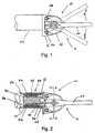
- FIG. 1is a side view of a bicycle shifter in accordance with one embodiment of the present invention
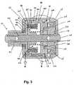
- FIG. 2is a cross-sectional side view of an attachment assembly for attaching the bicycle shifter of FIG. 1 to a handlebar;
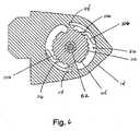
- FIG. 3ais a cross-sectional view taken along line A-A of the bicycle shifter of FIG. 1 in accordance with another embodiment of the present invention
- FIG. 4is an exploded view of a driver, a clutch mechanism and a takeup member of the shifter of FIG. 1 ;
- FIG. 5is a side view of a control lever of the control mechanism of the shifter of FIG. 1 ;
- FIG. 6is a cross-sectional view of a holding mechanism of the shifter of FIG. 1 ;
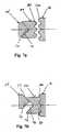
- FIG. 7ais a partial cross-sectional view taken along line B-B of the bicycle shifter of FIG. 3 showing the positions of the driver, clutch mechanism and the takeup member when the shifter is in a neutral position;
- FIG. 7bis a partial cross-sectional view taken along line B-B of the bicycle shifter of FIG. 3 showing the positions of the driver, clutch mechanism and the takeup member during a shifting operation;
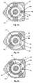
- FIG. 8ais cross-sectional view of the clutch mechanism and a rotational biasing member of the shifter of FIG. 1 when the shifter is in a rotational neutral position;
- FIG. 8bis a cross-sectional view of the clutch mechanism and the rotational biasing member of the shifter of FIG. 1 during a cable-pull operation;
- FIG. 8cis a cross-sectional view of the clutch mechanism and the rotational biasing member of the shifter of FIG. 1 during a cable-release operation.
- FIGS. 1-8illustrate a bicycle shifter 10 in accordance with one embodiment of the present invention.
- the bicycle shifter 10pulls or releases a control cable 12 connected to a gear change mechanism (not shown) to shift between gear positions of the bicycle.
- the gear change mechanismmay be a rear derailleur, a front derailleur or other similar type of mechanism.
- the bicycle shifter 10is shown as a time trial shifter for a road bike, however, the shifter 10 may be used on other types of bicycles such as a mountain bike.
- the shifter 10generally includes a housing 14, a control mechanism 16, a takeup member 18, a holding mechanism 20 and a return assembly 22. Looking to FIG.
- the housing 14includes a cover 44 screwed to the housing with three screws 46.
- the housing cover 44includes a bore 48 for receiving a bushing 50.
- a shaft 52extends through the housing 14 and is axially fixed relative to the housing 14 by a screw 54 threadably connected to an end 60 of the shaft 52 and a flange 58 also disposed at the end 60 of the shaft 52.
- the shaft 52has a shift axis that is substantially perpendicular to an axis of the handlebar.
- the control mechanism 16includes a control lever 62, a driver 64 and a clutch mechanism 66. Looking to FIG.
- the control lever 62is rotatable about the shaft 52 and includes first and second legs 72, 74 clamped to the driver 64 by a screw 76 extending through the first and second legs 72, 74.
- the screw 76is tightened causing the first leg 72 to move towards the second leg 74 resulting in a clamping force against the surface of the driver 64.
- the angular position of the control lever 62 relative to the housing 14may be adjusted by selecting the position of the lever 62 relative to the driver 64. This configuration allows the rider to adjust a neutral position of the control lever 62.
- the driver 64extends though the bushing 50 and is rotatably mounted to the shaft 52.
- a thrust bushing 68is disposed about the driver 64 between the control lever 62 and the housing cover 44.
- the driver 64 and clutch mechanism 66are configured to matingly engage.
- the driver 64axially and rotationally displaces the clutch mechanism 66 in response to actuation of the control lever 62.
- the driver 64includes two driver teeth 70 that engage the clutch mechanism 66.
- the clutch mechanism 66is rotatably mounted to the shaft 52.
- the clutch mechanism 66includes two recesses 78 for receiving the two driver teeth 70 and a plurality of clutch teeth 80 for engaging the takeup member 18.
- the driver teeth 70have angled surfaces 77 that are matingly engaged with corresponding angled surfaces 79 of the recesses 78 when the control lever is in the neutral position, see FIG. 7b .
- the clutch mechanismmay include teeth that are engageable with recesses of the driver.
- the clutch mechanism 66further includes a cavity 82 for receiving the return assembly 22.
- the return assembly 22includes a rotational biasing member 84 for rotationally biasing the clutch mechanism 66 to a rotational neutral position and an axial biasing member 86 for axially biasing the clutch mechanism 66 away from the takeup member 18 to an axial neutral position.
- the rotational biasing member 84is a torsion spring and the axially biasing member 86 is a compression spring.
- the torsion spring 84includes two legs 88, 90 that are engageable with an extension 92, in this embodiment a post extending from the clutch mechanism 66, and a projection 94 extending from the housing 14 to bias the clutch mechanism 66 toward its rotational neutral position.
- the ratchet wheel 104includes two projections 108 that are received in recesses 110 of the takeup member 18 to rotatably connect the ratchet wheel 104 to the takeup member 18.
- the projections 108are configured such that the ratchet wheel 104 has a small amount, in this embodiment approximately four degrees, of rotational play relative to the takeup member 18.
- the takeup member 18 and ratchet wheel 104may form one-piece, see FIG. 3a .
- the ratchet wheel 104is rotatably mounted to the shaft 52 and includes two sets of teeth 112 disposed about the periphery of the ratchet wheel 102.
- the teeth 112 on the ratchet wheel 102correspond to gear positions of the gear change mechanism.
- the detent springs 106include a first leg 114 supported by the housing and a second leg 116 engageable with the teeth 112 of the ratchet wheel 104 to retain the takeup member in the selected position.
- control lever 62At rest the control lever 62 is located in a neutral position as shown in FIG. 1 .
- the clutch mechanism 66is biased away from the takeup member 18 by the compression spring 86 as shown in FIG. 7a and is biased rotationally to the neutral position by the torsion spring 84 as shown in FIG. 8a .
- the control lever 62is rotated in a first direction A to pull the control cable and in a second direction B to release the control cable.
- the extension 92 of the clutch mechanism 66exerts a force against the leg 90 of the torsion spring 84 overcoming the biasing force of the torsion spring 84 and rotating the clutch mechanism 66 in the cable-pull direction, see FIG. 8b . Since the clutch teeth 80 are now engaged with the takeup teeth 100, the takeup member 18 and ratchet wheel 104 also rotate in the cable-pull direction resulting in the detent springs 106 to engage a next tooth on the ratchet wheel 104 corresponding to the next gear position of the gear change mechanism.
- the riderwould continue to rotate the control lever until the desired gear position was reached. With this configuration, the rider may shift multiple gears in the cable-pull direction with a single stroke of the control lever 62.
- the driver 64no longer exerts a force against the clutch mechanism 66 and the biasing force of the compression spring 86 causes the clutch mechanism 66 to displace away from the takeup member 18 back to its axial neutral position and the biasing force of the torsion spring 84 causes the clutch mechanism 66 to rotate back to its rotational neutral position as shown in FIG. 8a . Since the clutch mechanism 66 is coupled with the driver 64 and the driver 64 is coupled with the control lever 62, the driver 64 and the control lever 62 also return to their neutral positions. The takeup member 18 is retained in its current position by the detent springs 106 engaging the ratchet wheel teeth 112.
- the ridermay shift multiple gears in the cable-release direction with a single stroke of the control lever 62. Similar to the cable-pull operation, after the release of the control lever 62, the driver 64, clutch mechanism 66 and the control lever 62 return to their neutral position and the takeup member 18 is retained in its current position.
Landscapes
- Engineering & Computer Science (AREA)
- Mechanical Engineering (AREA)
- Chemical & Material Sciences (AREA)
- Combustion & Propulsion (AREA)
- Transportation (AREA)
- Steering Devices For Bicycles And Motorcycles (AREA)
- Gear-Shifting Mechanisms (AREA)
Description
- The present invention relates to bicycle shifters and more particularly to a bicycle shifter mountable to an end of a handlebar and having a control mechanism that returns to a neutral position after each shift operation.
- Bicycle racing is becoming an increasingly popular and competitive sport. One type of bicycle racing is time trials where the cyclist races against the clock for a certain distance. During these time trials, the aerodynamics of both the bicycle and rider are very important. Typically, a time trial bicycle will have hook-type handlebars. This type of handlebar is generally u-shaped with the "u" pointing in the riding direction and the end of each side of the "u" is turned upwardly. A typical shifter is mounted to the end of each side of the "u." One disadvantage of these shifters is that they increase the aerodynamic drag encountered by the rider because the lever does not return to a neutral position after each shift operation rather the neutral position of the lever changes depending on which gear is selected. Furthermore, this configuration is not ergonomic and has a complicated design. Accordingly, there is a need for a simple shifter that is mountable to an end of a handlebar that returns to an aerodynamic/ergonomic position.
EP 0 601 211 A1 discloses a bicycle brake lever assembly according to the preamble of claim 1 including a return-to-center speed change lever pivotal relative to a housing of the brake lever assembly and a speed change operation mechanism disposed in the housing behind the brake lever assemby. The brake lever assembly is disposed at a front end portion of a generally U-shaped curved portion formed downwardly at each end portion of a drop handlebar. Accordingly, the speed change lever included in the brake lever assembly is also arranged at this front end portion of the handlebar.US 5,737,967 discloses a handlebar, by which gear shift levers are secured to the outer ends of the handlebars.- The present invention provides a bicycle shifter for pulling and releasing a control cable connected to a gear change mechanism. The bicycle shifter includes a housing, a takeup member, a control mechanism, a holding mechanism and a return assembly. An attachment assembly mounts the housing at or near an end of a bicycle handlebar. The takeup member is rotatable about a shift axis for winding and unwinding the control cable thereon in a cable-pull direction and a cable-release direction. Preferably, the shift axis is substantially perpendicular to an axis of the handlebar. The control mechanism is movable in a first direction to rotate the takeup member in the cable-pull direction and in a second direction opposite the first direction to rotate the takeup member in the cable-release direction. The holding mechanism retains the takeup member in a selected position. The return assembly returns the control mechanism to a neutral position after each shift operation to decrease the aerodynamic drag encountered by the rider.
- In one embodiment of the present invention, the control mechanism includes a control lever, a driver rotatably coupled to the control lever and a clutch mechanism operatively coupled to the driver for transferring the motion of the control lever to the takeup member. The control lever is rotatable about the shift axis in the first and second directions to pull and release the control cable and sweeps substantially perpendicular to the handlebar axis. The driver and clutch mechanism are configured to matingly engage. The clutch mechanism is biased toward the driver in the neutral position. In response to the actuation of the control lever, the driver axially and rotationally displaces the clutch mechanism toward the takeup member to transfer the motion of the control lever to the takeup member.
- in one embodiment, the driver is rotatable about the shift axis and includes at least two teeth engageable with at least two recesses of the clutch mechanism. The driver teeth include angled surfaces corresponding to angled surfaces of the recesses of the clutch mechanism. Alternatively, the clutch mechanism may include teeth that engage recesses of the driver. The clutch mechanism is rotatable about the shift axis and includes a plurality of clutch teeth engageable with a plurality of takeup teeth of the takeup member in response to actuation of the control lever. With this configuration, when the control lever is actuated, the driver rotates, forcing the angled recesses of the clutch mechanism to move along the angled surfaces of the driver teeth causing the clutch mechanism to displace axially away from the driver toward the takeup member until the clutch teeth engage the takeup teeth. Once the takeup member stops the clutch mechanism from displacing axially, the clutch mechanism starts to rotate. Since the clutch teeth are now engaged with the takeup teeth, the takeup member also rotates.
- The return assembly includes a rotational biasing member for rotationally biasing the clutch mechanism to a rotational neutral position and an axial biasing member for axially biasing the clutch mechanism to an axial neutral position away from the takeup member and toward the driver. In one embodiment, the rotational biasing member may be a torsion spring and the axial biasing member is a compression spring disposed between the clutch mechanism and the takeup member. After each shift operation, the torsion spring rotates the clutch mechanism back to its rotational neutral position and the compression spring axially displaces the clutch mechanism away from the takeup member and toward the driver to its axial neutral position. The holding mechanism includes a ratchet wheel and at least one detent spring. The ratchet wheel is rotatably coupled to the takeup member and includes a plurality of teeth that correspond to gear positions of the gear change mechanism. The detent spring engages the plurality of teeth to retain the ratchet wheel and the takeup member in the selected position.
- These and other features and advantages of the present invention will be more fully understood from the following description of one embodiment of the invention, taken together with the accompanying drawings.
- In the drawings:
FIG. 1 is a side view of a bicycle shifter in accordance with one embodiment of the present invention;FIG. 2 is a cross-sectional side view of an attachment assembly for attaching the bicycle shifter ofFIG. 1 to a handlebar;FIG. 3 is a cross-sectional view taken along line A-A of the bicycle shifter ofFIG. 1 ;FIG. 3a is a cross-sectional view taken along line A-A of the bicycle shifter ofFIG. 1 in accordance with another embodiment of the present invention;FIG. 4 is an exploded view of a driver, a clutch mechanism and a takeup member of the shifter ofFIG. 1 ;FIG. 5 is a side view of a control lever of the control mechanism of the shifter ofFIG. 1 ;FIG. 6 is a cross-sectional view of a holding mechanism of the shifter ofFIG. 1 ;FIG. 7a is a partial cross-sectional view taken along line B-B of the bicycle shifter ofFIG. 3 showing the positions of the driver, clutch mechanism and the takeup member when the shifter is in a neutral position;FIG. 7b is a partial cross-sectional view taken along line B-B of the bicycle shifter ofFIG. 3 showing the positions of the driver, clutch mechanism and the takeup member during a shifting operation;FIG. 8a is cross-sectional view of the clutch mechanism and a rotational biasing member of the shifter ofFIG. 1 when the shifter is in a rotational neutral position;FIG. 8b is a cross-sectional view of the clutch mechanism and the rotational biasing member of the shifter ofFIG. 1 during a cable-pull operation; andFIG. 8c is a cross-sectional view of the clutch mechanism and the rotational biasing member of the shifter ofFIG. 1 during a cable-release operation.FIGS. 1-8 illustrate abicycle shifter 10 in accordance with one embodiment of the present invention. Thebicycle shifter 10 pulls or releases acontrol cable 12 connected to a gear change mechanism (not shown) to shift between gear positions of the bicycle. The gear change mechanism may be a rear derailleur, a front derailleur or other similar type of mechanism. Thebicycle shifter 10 is shown as a time trial shifter for a road bike, however, theshifter 10 may be used on other types of bicycles such as a mountain bike. In this embodiment, theshifter 10 generally includes ahousing 14, acontrol mechanism 16, atakeup member 18, aholding mechanism 20 and areturn assembly 22. Looking toFIG. 2 , theshifter 10 is mounted at or near anend 24 of ahandlebar 26 by anattachment assembly 28 inserted into theend 24 of thehandlebar 26. Theattachment assembly 28 includes abolt 30 threadably connected to theshifter housing 14, threewedges 32 disposed about thebolt 30 and awedge spring 34 disposed about the threewedges 32. Thewedge spring 34 biases thewedges 32 radially inward towards the bolt. Thebolt 30 includes asocket 36 for receiving a tool such as a hex wrench. To secure theshifter 10 at or near theend 24 of thehandlebar 26, the tool is inserted into thesocket 36 and rotated, moving thebolt 30 towards thehousing 14. As thebolt 30 moves toward thehousing 14, taperedsurfaces bolt 30 andhousing 14, respectively, deflect thewedges 32 radially outward against theinner surface 42 of thehandlebar 26 securing theshifter 10 to end 24 of thehandlebar 26. Of course, other assemblies for attaching theshifter 10 to thehandlebar 26 may be used.- Looking to
FIGS. 1 ,3 and4 , thehousing 14 includes acover 44 screwed to the housing with threescrews 46. Thehousing cover 44 includes abore 48 for receiving abushing 50. Ashaft 52 extends through thehousing 14 and is axially fixed relative to thehousing 14 by ascrew 54 threadably connected to anend 60 of theshaft 52 and aflange 58 also disposed at theend 60 of theshaft 52. Theshaft 52 has a shift axis that is substantially perpendicular to an axis of the handlebar. In one embodiment of the present invention, thecontrol mechanism 16 includes acontrol lever 62, adriver 64 and aclutch mechanism 66. Looking toFIG. 5 , thecontrol lever 62 is rotatable about theshaft 52 and includes first andsecond legs driver 64 by ascrew 76 extending through the first andsecond legs control lever 62 on thedriver 64, thescrew 76 is tightened causing thefirst leg 72 to move towards thesecond leg 74 resulting in a clamping force against the surface of thedriver 64. The angular position of thecontrol lever 62 relative to thehousing 14 may be adjusted by selecting the position of thelever 62 relative to thedriver 64. This configuration allows the rider to adjust a neutral position of thecontrol lever 62. - Looking to
FIGS. 3 and4 , thedriver 64 extends though thebushing 50 and is rotatably mounted to theshaft 52. Athrust bushing 68 is disposed about thedriver 64 between thecontrol lever 62 and thehousing cover 44. Thedriver 64 andclutch mechanism 66 are configured to matingly engage. Thedriver 64 axially and rotationally displaces theclutch mechanism 66 in response to actuation of thecontrol lever 62. In this embodiment, thedriver 64 includes twodriver teeth 70 that engage theclutch mechanism 66. Theclutch mechanism 66 is rotatably mounted to theshaft 52. Theclutch mechanism 66 includes tworecesses 78 for receiving the twodriver teeth 70 and a plurality ofclutch teeth 80 for engaging thetakeup member 18. Thedriver teeth 70 have angledsurfaces 77 that are matingly engaged with correspondingangled surfaces 79 of therecesses 78 when the control lever is in the neutral position, seeFIG. 7b . Alternatively, the clutch mechanism may include teeth that are engageable with recesses of the driver. Theclutch mechanism 66 further includes acavity 82 for receiving thereturn assembly 22. - The
return assembly 22 includes arotational biasing member 84 for rotationally biasing theclutch mechanism 66 to a rotational neutral position and anaxial biasing member 86 for axially biasing theclutch mechanism 66 away from thetakeup member 18 to an axial neutral position. In this embodiment, the rotational biasingmember 84 is a torsion spring and theaxially biasing member 86 is a compression spring. Looking toFIG. 8a , thetorsion spring 84 includes twolegs extension 92, in this embodiment a post extending from theclutch mechanism 66, and aprojection 94 extending from thehousing 14 to bias theclutch mechanism 66 toward its rotational neutral position. Aspring retainer 96 is attached to theclutch mechanism 66 by twoscrews 98 to prevent thetorsion spring 84 from axially moving relative to theclutch mechanism 66. Thecompression spring 86 is disposed between theclutch mechanism 66 and thetakeup member 18. Looking toFIG. 7a , the compression spring biases theclutch mechanism 66 toward thedriver 64 and away from thetakeup member 18. - Looking to
FIGS. 3 and4 , thetakeup member 18, in this embodiment a spool, is rotatably mounted to theshaft 52. Thecompression spring 86 biases thetakeup member 18 away from the clutching mechanism. Thetakeup member 18 includes a plurality oftakeup teeth 100 located around the periphery of thetakeup member 18 for engaging theclutch teeth 80 of theclutch mechanism 66. Thetakeup member 18 further includes agroove 102 for receiving thecontrol cable 12. Thegroove 102 extends along the periphery of thetakeup member 18. Thetakeup member 18 is held in a selected position by the holdingmechanism 20. The holdingmechanism 20 includes aratchet wheel 104 and two detent springs 106. Theratchet wheel 104 includes twoprojections 108 that are received in recesses 110 of thetakeup member 18 to rotatably connect theratchet wheel 104 to thetakeup member 18. Theprojections 108 are configured such that theratchet wheel 104 has a small amount, in this embodiment approximately four degrees, of rotational play relative to thetakeup member 18. Alternatively, thetakeup member 18 andratchet wheel 104 may form one-piece, seeFIG. 3a . Looking toFIG. 6 , theratchet wheel 104 is rotatably mounted to theshaft 52 and includes two sets ofteeth 112 disposed about the periphery of theratchet wheel 102. Theteeth 112 on theratchet wheel 102 correspond to gear positions of the gear change mechanism. The detent springs 106 include afirst leg 114 supported by the housing and asecond leg 116 engageable with theteeth 112 of theratchet wheel 104 to retain the takeup member in the selected position. - At rest the
control lever 62 is located in a neutral position as shown inFIG. 1 . When thecontrol lever 62 is in the neutral position, theclutch mechanism 66 is biased away from thetakeup member 18 by thecompression spring 86 as shown inFIG. 7a and is biased rotationally to the neutral position by thetorsion spring 84 as shown inFIG. 8a . To shift the gear change mechanism, thecontrol lever 62 is rotated in a first direction A to pull the control cable and in a second direction B to release the control cable. When thecontrol lever 62 is rotated in the cable-pull direction, thedriver 64 rotates with thecontrol lever 62 and as thedriver teeth 70 of thedriver 64 rotate, therecesses 78 of theclutch mechanism 66 move alongangled surfaces 77 of thedriver teeth 70, axially displacing theclutch mechanism 66 toward thetakeup member 18 until theclutch teeth 80 ofclutch mechanism 66 engage thetakeup teeth 100 of thetakeup member 18 as shown inFIG. 7b . Once theclutch mechanism 66 is prevented from displacing any further in the axial direction by thetakeup member 18, theextension 92 of theclutch mechanism 66 exerts a force against theleg 90 of thetorsion spring 84 overcoming the biasing force of thetorsion spring 84 and rotating theclutch mechanism 66 in the cable-pull direction, seeFIG. 8b . Since theclutch teeth 80 are now engaged with thetakeup teeth 100, thetakeup member 18 andratchet wheel 104 also rotate in the cable-pull direction resulting in the detent springs 106 to engage a next tooth on theratchet wheel 104 corresponding to the next gear position of the gear change mechanism. If the rider wanted to shift more than one gear at a time in the cable-pull direction, the rider would continue to rotate the control lever until the desired gear position was reached. With this configuration, the rider may shift multiple gears in the cable-pull direction with a single stroke of thecontrol lever 62. - After the
control lever 62 is released, thedriver 64 no longer exerts a force against theclutch mechanism 66 and the biasing force of thecompression spring 86 causes theclutch mechanism 66 to displace away from thetakeup member 18 back to its axial neutral position and the biasing force of thetorsion spring 84 causes theclutch mechanism 66 to rotate back to its rotational neutral position as shown inFIG. 8a . Since theclutch mechanism 66 is coupled with thedriver 64 and thedriver 64 is coupled with thecontrol lever 62, thedriver 64 and thecontrol lever 62 also return to their neutral positions. Thetakeup member 18 is retained in its current position by the detent springs 106 engaging theratchet wheel teeth 112. - When the
control lever 62 is rotated in the cable-release direction, similar to the cable-pull operation, thedriver 64 rotates with thecontrol lever 62 and as thedriver teeth 70 rotate, therecesses 78 of theclutch mechanism 66 move along theangled surfaces 77 of thedrive teeth 70 axially displacing theclutch mechanism 66 toward thetakeup member 18 until theclutch teeth 80 of theclutch mechanism 66 engage thetakeup teeth 100 of thetakeup member 18. Looking toFIG. 8c , once theclutch mechanism 66 is prevented from displacing any further in the axial direction by thetakeup member 18, theextension 92 of theclutch mechanism 66 exerts a force against theleg 88 of thetorsion spring 84 overcoming the biasing force of thetorsion spring 84 and rotating in the cable-release direction. Thetakeup member 18 andratchet wheel 104 rotate in the cable-release direction resulting in the detent springs 106 engaging a next tooth in the cable-release direction. If the rider wanted to shift more than one gear at a time in the cable-release direction, the rider would continue to rotate thecontrol lever 62 until the desired gear position was reached. With this configuration, the rider may shift multiple gears in the cable-release direction with a single stroke of thecontrol lever 62. Similar to the cable-pull operation, after the release of thecontrol lever 62, thedriver 64,clutch mechanism 66 and thecontrol lever 62 return to their neutral position and thetakeup member 18 is retained in its current position. - While this invention has been described in reference to a preferred embodiment, it should be understood that numerous changes could be made within the scope of the inventive concepts described. Accordingly, it is intended that the invention not be limited to the disclosed embodiment, but that it have the full scope permitted by the language of the following claims.
Claims (25)
- A bicycle shifter (10) for pulling and releasing a control cable (12) connected to a gear change mechanism, the bicycle shifter (10) comprising:a housing (14) comprising an attachment assembly (28) mountable to a distal end (24) of a handlebar (26);a takeup member (18) rotatable about a shift axis for winding and unwinding the control cable (12) thereon in a cable-pull direction and a cable-release direction;a control mechanism (16) movable in a first direction to rotate the takeup member (18) in the cable-pull direction and in a second direction opposite the first direction to rotate the takeup member (18) in the cable-release direction; the control mechanism (16) including a control lever (62) rotatable about the shift axis and a driver (64) rotatably coupled to the control lever (62);a holding mechanism (20) for retaining the takeup member (18) in a selected position; anda return assembly (22) for returning the control lever (62) to a neutral position after each shift operation,characterized in thatthe control lever (62) neutral position is adjustable relative to the axis of the handlebar end (24), andin that said control lever (62) is clamped to the driver (64) such that the aerodynamic drag of the control lever (62) in the neutral position is reduced."
- A bicycle shifter (10) for pulling and releasing a control cable (12) connected to a gear change mechanism, the bicycle shifter (10) comprising:a housing (14) mountable to or near an end of a handlebar (26);a takeup member (18) rotatable about a shift axis for winding and unwinding the control cable (12) thereon in a cable-pull direction and a cable-release direction;a control mechanism (16) including a control lever (62) rotatable in a first direction to rotate the takeup member (18) in the cable-pull direction and in a second direction to rotate the takeup member (18) in the cable-release direction; the control mechanism (16) including a clutch mechanism (66) axially displaceable to engage the takeup member (18) in response to actuation of the control lever (62) to transfer the motion of the control lever (62) to the takeup member (18);a holding mechanism (20) for retaining the takeup member (18) in a selected position; anda return assembly (22) for returning the control mechanism (16) to a neutral position after each shift operation.
- The bicycle shifter of claim 2, wherein the shift axis is substantially parallel to an axis of the handlebar (26).
- The bicycle shifter of claim 2, wherein the control mechanism (16) includes a driver (64) rotatably coupled to the control lever (62) and operatively coupled to the clutch mechanism (66), the clutch mechanism (66) rotatable about the shift axis, and the control lever (62) rotatable about the shift axis.
- The bicycle shifter of claim 1, wherein the takeup member (18) is rotatable about the shift axis substantially perpendicular to an axis of the handlebar (26).
- The bicycle shifter of claim 1 or 2, wherein the control lever (62) sweeps substantially perpendicular to an axis of the end of the handlebar (26).
- The bicycle shifter of claim 1, wherein the control mechanism (16) includes a clutch mechanism (66) axially displaceable to engage the takeup member (18) in response to actuation of the control mechanism (16) to transfer motion of the control mechanism (16) to the takeup member (18).
- The bicycle shifter of claim 7, wherein the control mechanism (16) includes a driver (64) rotatably coupled to the control lever (62), the clutch mechanism (66) operatively coupled to the driver (64) and rotatable about the shift axis.
- The bicycle shifter of claim 4 or 8, wherein the return assembly (22) includes a rotational biasing member (84) and an axial biasing member (86), the rotational biasing member (84) rotationally biases the clutch mechanism (66) to a rotational neutral position and the axial biasing member (86) axially biases the clutch mechanism (66) to an axial neutral position away from the takeup member (18) and toward the driver (64).
- The bicycle shifter of claim 9, wherein the clutch mechanism (66) includes an extension (92), the housing (14) includes a projection (94) and the rotational biasing member (84) is a torsion spring, the torsion spring (84) engageable with the projection (94) and the extension (92) to bias the clutch mechanism (66) toward the rotational neutral position.
- The bicycle shifter of claim 10, wherein the torsion spring (84) includes first and second ends (88, 90), one of the first and second ends (88, 90) engageable with the extension (92) and the other one of the first and second ends (88, 90) engageable with the projection (94).
- The bicycle shifter of claim 9, wherein the axial biasing member (86) is a compression spring disposed between the clutch mechanism (66) and takeup member (18).
- The bicycle shifter of claim 4 or 8, wherein the driver (64) and the clutch mechanism (66) configured to matingly engage, the driver (64) axially and rotationally displacing the clutch mechanism (66) in response to actuation of the control lever (62).
- The bicycle shifter of claim 13, wherein one of the driver (64) and the clutch mechanism (66) includes at least two teeth (70) and the other one of the driver (64) and the clutch mechanism (66) includes at least two recesses (78) for receiving the teeth (70).
- The bicycle shifter of claim 14, wherein the at least two teeth (70) have angled surfaces (77) and the recesses (78) have corresponding angled surfaces (79) matingly engageable with the angled surfaces (77) of the teeth (70).
- The bicycle shifter of claim 2 or 8, wherein the takeup member (18) includes a plurality of takeup teeth (100) and the clutch mechanism (66) includes a plurality of clutch teeth (80) engageable with the plurality of takeup teeth (100) to rotate the takeup member (18) about the shift axis in response to actuation of the control lever (62), the clutch teeth (80) biased away from the takeup teeth (100) when the control lever (62) is in the neutral position.
- The bicycle shifter of claim 4 or 8, wherein the control lever (62) is clamped to the driver (64).
- The bicycle shifter of claim 1 or 2, wherein the holding mechanism (20) includes a ratchet wheel (104) rotatable with the takeup member (18) and at least one detent spring (106), the ratchet wheel (104) having a plurality of teeth (112), the detent spring (106) engageable with the plurality of teeth (112) of the ratchet wheel (104) to retain the takeup member (18) in the selected position.
- The bicycle shifter of claim 18, wherein the detent springs (106) have first and second ends (114,116), one of the first and second ends (114, 116) supported by the housing (14) and the other one of the first and second ends (114,116) engageable with the teeth (112) of the ratchet wheel (104).
- The bicycle shifter of claim 18, wherein the takeup member (18) includes recesses (110) and the ratchet wheel (104) includes projections (108) engageable with the recesses (110) to rotatably couple the ratchet wheel (104) to the takeup member (18).
- The bicycle shifter of claim 18, wherein the ratchet wheel (104) and the takeup member (18) are integral.
- The bicycle shifter of claim 1, further comprising an attachment assembly (28) adapted to be inserted into the end of the handlebar (26).
- The bicycle shifter of claim 1, wherein the control lever neutral position is adjustable relative to the axis of the handlebar end.
- The bicycle shifter of claim 1 or any one of claims 5 to 22, wherein the control lever (62), in the neutral position, extends substantially parallel to the axis of the handlebar end.
- The bicycle shifter of claim 23, wherein the control mechanism further includes a driver (64), the control lever (62) includes first and second legs (72, 74) clamped to the driver (64) of the control mechanism by a screw (76) extending through the first and second legs (72, 74), and the control lever neutral position is adjustable relative to the axis of the handlebar end by selecting the position of the lever (62) relative to the driver (64).
Applications Claiming Priority (1)
| Application Number | Priority Date | Filing Date | Title |
|---|---|---|---|
| US11/277,249US9446813B2 (en) | 2006-03-23 | 2006-03-23 | Bicycle shifter |
Publications (3)
| Publication Number | Publication Date |
|---|---|
| EP1837275A2 EP1837275A2 (en) | 2007-09-26 |
| EP1837275A3 EP1837275A3 (en) | 2009-06-17 |
| EP1837275B1true EP1837275B1 (en) | 2013-11-27 |
Family
ID=37905878
Family Applications (1)
| Application Number | Title | Priority Date | Filing Date |
|---|---|---|---|
| EP07005919.1AActiveEP1837275B1 (en) | 2006-03-23 | 2007-03-22 | Bicycle shifter |
Country Status (4)
| Country | Link |
|---|---|
| US (1) | US9446813B2 (en) |
| EP (1) | EP1837275B1 (en) |
| CN (1) | CN101092157B (en) |
| TW (1) | TWI333918B (en) |
Families Citing this family (11)
| Publication number | Priority date | Publication date | Assignee | Title |
|---|---|---|---|---|
| DE102008048134C5 (en)* | 2008-09-20 | 2018-09-27 | Sram Deutschland Gmbh | Switch for actuating a transmission on a bicycle |
| US8978511B2 (en)* | 2010-11-09 | 2015-03-17 | Shimano Inc. | Position control mechanism |
| EP2460716B1 (en)* | 2010-12-03 | 2014-05-07 | Campagnolo S.r.l. | Control lever and actuation device of a bicycle gearshift of the bar-end type |
| EP2468614B1 (en)* | 2010-12-03 | 2013-10-02 | Campagnolo S.r.l. | Actuation device for a control cable for a bicycle gearshift |
| US10207772B2 (en) | 2011-01-28 | 2019-02-19 | Paha Designs, Llc | Gear transmission and derailleur system |
| US9033833B2 (en) | 2011-01-28 | 2015-05-19 | Paha Designs, Llc | Gear transmission and derailleur system |
| US9327792B2 (en) | 2011-01-28 | 2016-05-03 | Paha Designs, Llc | Gear transmission and derailleur system |
| EP2562070B1 (en)* | 2011-08-26 | 2015-02-18 | Campagnolo S.r.l. | Actuation device of a bar-end bicycle gearshift |
| US10279867B2 (en)* | 2015-05-29 | 2019-05-07 | Shimano Inc. | Bicycle operating device |
| US10167041B2 (en)* | 2016-11-01 | 2019-01-01 | Shimano Inc. | Bicycle operating device |
| US10618599B2 (en)* | 2017-01-27 | 2020-04-14 | Shimano Inc. | Bicycle operating device |
Citations (2)
| Publication number | Priority date | Publication date | Assignee | Title |
|---|---|---|---|---|
| US4938733A (en)* | 1988-01-06 | 1990-07-03 | Sram Corporation | Bicycle gear shifting method and apparatus |
| US5737967A (en)* | 1993-05-27 | 1998-04-14 | Hartley; James T. | Pivoting handlebars |
Family Cites Families (23)
| Publication number | Priority date | Publication date | Assignee | Title |
|---|---|---|---|---|
| US2583609A (en)* | 1943-09-06 | 1952-01-29 | Brev Souhart S A | Control means for chain shifting change-speed gears for cycles |
| US2999706A (en)* | 1959-05-06 | 1961-09-12 | Aladdin Mfg Company | Tube lock |
| US4462267A (en)* | 1980-03-01 | 1984-07-31 | Shimano Industrial Company, Limited | Handlebar for a bicycle |
| IT1209673B (en)* | 1985-11-19 | 1989-08-30 | Sarano Di Santa Lucia Di Piave | BRAKE OPERATION DEVICE FOR BICYCLES, IN PARTICULAR FOR RACING BICYCLES. |
| EP0352732B1 (en)* | 1988-07-29 | 1995-02-15 | Shimano Inc. | Handlebar-mounted gear change lever |
| EP0371429B1 (en)* | 1988-11-29 | 1993-07-28 | Shimano Inc. | Speed control apparatus for a bicycle |
| JP2848842B2 (en)* | 1989-04-11 | 1999-01-20 | 株式会社シマノ | Gear lever for bicycle |
| JP3245188B2 (en)* | 1991-04-19 | 2002-01-07 | 株式会社シマノ | Speed change device for bicycle |
| JPH0616170A (en) | 1992-07-02 | 1994-01-25 | Maeda Kogyo Kk | Brake lever device for bicycle |
| US5285696A (en)* | 1992-09-21 | 1994-02-15 | Answer Products, Inc. | Bar end assembly attachable to the steerer bars of bicycle handlebar systems |
| JP2601207Y2 (en)* | 1992-12-28 | 1999-11-15 | 株式会社シマノ | Speed change device for bicycle |
| IT1261550B (en) | 1993-04-20 | 1996-05-23 | Antonio Romano | CONTROL DEVICE FOR THE CHANGE OF A BICYCLE. |
| US5799542A (en)* | 1995-10-11 | 1998-09-01 | Shimano, Inc. | Bicycle shift control device |
| US5678455A (en)* | 1996-02-15 | 1997-10-21 | Shimano, Inc. | Bar-end shifting device |
| JP3678496B2 (en) | 1996-05-30 | 2005-08-03 | 株式会社シマノ | Bicycle shifting operation device |
| DE19734685A1 (en)* | 1997-08-11 | 1999-02-18 | Sram De Gmbh | Latch switch, in particular twist grip switch for controlling a bicycle transmission |
| US6095309A (en)* | 1998-11-12 | 2000-08-01 | At Design Inc. | Cycle handlebar actuator |
| FR2792865B1 (en)* | 1999-04-27 | 2001-06-15 | Cie Generale De Participations | DEVICE FOR REMOTE CONTROL OF MOTION, IN PARTICULAR OF GRIPPING MEMBERS |
| US6648527B2 (en)* | 2000-04-28 | 2003-11-18 | Heiwa Tokei Manufacturing Co., Ltd. | Mechanism for adjusting tension of an inked ribbon of a printer |
| US7698967B2 (en)* | 2004-10-29 | 2010-04-20 | Compositech, Inc. | Bicycle handlebar with removable and adjustable aerobar |
| US7305903B2 (en)* | 2004-11-08 | 2007-12-11 | Shimano Inc. | Bicycle shift operating device |
| US7340975B2 (en)* | 2004-12-21 | 2008-03-11 | Shimano, Inc. | Bicycle control apparatus with a position setting idler member |
| US7565848B2 (en)* | 2006-01-13 | 2009-07-28 | Shimano Inc. | Bicycle control device |
- 2006
- 2006-03-23USUS11/277,249patent/US9446813B2/ennot_activeExpired - Fee Related
- 2007
- 2007-03-22TWTW096109908Apatent/TWI333918B/enactive
- 2007-03-22EPEP07005919.1Apatent/EP1837275B1/enactiveActive
- 2007-03-23CNCN200710089449XApatent/CN101092157B/ennot_activeExpired - Fee Related
Patent Citations (2)
| Publication number | Priority date | Publication date | Assignee | Title |
|---|---|---|---|---|
| US4938733A (en)* | 1988-01-06 | 1990-07-03 | Sram Corporation | Bicycle gear shifting method and apparatus |
| US5737967A (en)* | 1993-05-27 | 1998-04-14 | Hartley; James T. | Pivoting handlebars |
Also Published As
| Publication number | Publication date |
|---|---|
| EP1837275A2 (en) | 2007-09-26 |
| US9446813B2 (en) | 2016-09-20 |
| TWI333918B (en) | 2010-12-01 |
| TW200800716A (en) | 2008-01-01 |
| US20070221008A1 (en) | 2007-09-27 |
| CN101092157B (en) | 2011-08-31 |
| EP1837275A3 (en) | 2009-06-17 |
| CN101092157A (en) | 2007-12-26 |
Similar Documents
| Publication | Publication Date | Title |
|---|---|---|
| EP1837275B1 (en) | Bicycle shifter | |
| US7779718B2 (en) | Bicycle shifter | |
| EP2174862B1 (en) | Bicycle control device | |
| US9199688B2 (en) | Bicycle control device | |
| EP1728714B1 (en) | Bicycle control device | |
| EP1724189B1 (en) | Position control mechanism for bicycle control device | |
| US8695451B2 (en) | Bicycle control device | |
| US10597109B2 (en) | Bicycle component positioning device | |
| US7849764B2 (en) | Bicycle shift operating device | |
| US20080295636A1 (en) | Bicycle control device | |
| EP1854713A2 (en) | Bicycle shifting mechanism | |
| US20080295635A1 (en) | Bicycle control device | |
| US10450034B2 (en) | Bicycle operating device | |
| US20170050465A1 (en) | Rear Hub and Bicycle Axle | |
| US8881619B2 (en) | Bicycle control device | |
| US10648525B2 (en) | Cable adjuster | |
| EP2157011B1 (en) | Cable operating mechanism | |
| US20180134342A1 (en) | Bicycle component operating device | |
| EP2615024B1 (en) | Speed adjusting device of a speed changer | |
| US10207768B2 (en) | Bicycle operating device | |
| TW202523569A (en) | Operating device for human powered vehicle | |
| US20070186714A1 (en) | Bicycle cable connection arrangement |
Legal Events
| Date | Code | Title | Description |
|---|---|---|---|
| PUAI | Public reference made under article 153(3) epc to a published international application that has entered the european phase | Free format text:ORIGINAL CODE: 0009012 | |
| AK | Designated contracting states | Kind code of ref document:A2 Designated state(s):AT BE BG CH CY CZ DE DK EE ES FI FR GB GR HU IE IS IT LI LT LU LV MC MT NL PL PT RO SE SI SK TR | |
| AX | Request for extension of the european patent | Extension state:AL BA HR MK YU | |
| RAP1 | Party data changed (applicant data changed or rights of an application transferred) | Owner name:SRAM, LLC. | |
| 111Z | Information provided on other rights and legal means of execution | Free format text:AT BE BG CH CY CZ DE DK EE ES FI FR GB GR HU IE IS IT LT LU LV MC MT NL PL PT RO SE SI SK TR Effective date:20090106 | |
| PUAL | Search report despatched | Free format text:ORIGINAL CODE: 0009013 | |
| AK | Designated contracting states | Kind code of ref document:A3 Designated state(s):AT BE BG CH CY CZ DE DK EE ES FI FR GB GR HU IE IS IT LI LT LU LV MC MT NL PL PT RO SE SI SK TR | |
| AX | Request for extension of the european patent | Extension state:AL BA HR MK RS | |
| 17P | Request for examination filed | Effective date:20091204 | |
| AKX | Designation fees paid | Designated state(s):DE FR NL | |
| 17Q | First examination report despatched | Effective date:20100506 | |
| RIC1 | Information provided on ipc code assigned before grant | Ipc:B62K 23/06 20060101ALI20130130BHEP Ipc:B62M 25/04 20060101AFI20130130BHEP | |
| GRAP | Despatch of communication of intention to grant a patent | Free format text:ORIGINAL CODE: EPIDOSNIGR1 | |
| GRAS | Grant fee paid | Free format text:ORIGINAL CODE: EPIDOSNIGR3 | |
| GRAP | Despatch of communication of intention to grant a patent | Free format text:ORIGINAL CODE: EPIDOSNIGR1 | |
| INTG | Intention to grant announced | Effective date:20130924 | |
| GRAA | (expected) grant | Free format text:ORIGINAL CODE: 0009210 | |
| AK | Designated contracting states | Kind code of ref document:B1 Designated state(s):DE FR NL | |
| REG | Reference to a national code | Ref country code:NL Ref legal event code:T3 | |
| REG | Reference to a national code | Ref country code:DE Ref legal event code:R096 Ref document number:602007033992 Country of ref document:DE Effective date:20140123 | |
| REG | Reference to a national code | Ref country code:DE Ref legal event code:R097 Ref document number:602007033992 Country of ref document:DE | |
| PLBE | No opposition filed within time limit | Free format text:ORIGINAL CODE: 0009261 | |
| STAA | Information on the status of an ep patent application or granted ep patent | Free format text:STATUS: NO OPPOSITION FILED WITHIN TIME LIMIT | |
| 26N | No opposition filed | Effective date:20140828 | |
| REG | Reference to a national code | Ref country code:DE Ref legal event code:R097 Ref document number:602007033992 Country of ref document:DE Effective date:20140828 | |
| REG | Reference to a national code | Ref country code:FR Ref legal event code:PLFP Year of fee payment:10 | |
| REG | Reference to a national code | Ref country code:FR Ref legal event code:PLFP Year of fee payment:11 | |
| PGFP | Annual fee paid to national office [announced via postgrant information from national office to epo] | Ref country code:NL Payment date:20170320 Year of fee payment:11 Ref country code:FR Payment date:20170213 Year of fee payment:11 | |
| REG | Reference to a national code | Ref country code:NL Ref legal event code:MM Effective date:20180401 | |
| PG25 | Lapsed in a contracting state [announced via postgrant information from national office to epo] | Ref country code:NL Free format text:LAPSE BECAUSE OF NON-PAYMENT OF DUE FEES Effective date:20180401 | |
| PG25 | Lapsed in a contracting state [announced via postgrant information from national office to epo] | Ref country code:FR Free format text:LAPSE BECAUSE OF NON-PAYMENT OF DUE FEES Effective date:20180331 | |
| REG | Reference to a national code | Ref country code:DE Ref legal event code:R082 Ref document number:602007033992 Country of ref document:DE Representative=s name:THUM, MOETSCH, WEICKERT PATENTANWAELTE PARTG M, DE Ref country code:DE Ref legal event code:R082 Ref document number:602007033992 Country of ref document:DE Representative=s name:THUM & PARTNER THUM MOETSCH WEICKERT PATENTANW, DE | |
| P01 | Opt-out of the competence of the unified patent court (upc) registered | Effective date:20230525 | |
| PGFP | Annual fee paid to national office [announced via postgrant information from national office to epo] | Ref country code:DE Payment date:20250210 Year of fee payment:19 |