EP1836978B1 - Instrument assembly for use in performing spinal surgery - Google Patents
Instrument assembly for use in performing spinal surgeryDownload PDFInfo
- Publication number
- EP1836978B1 EP1836978B1EP07111192AEP07111192AEP1836978B1EP 1836978 B1EP1836978 B1EP 1836978B1EP 07111192 AEP07111192 AEP 07111192AEP 07111192 AEP07111192 AEP 07111192AEP 1836978 B1EP1836978 B1EP 1836978B1
- Authority
- EP
- European Patent Office
- Prior art keywords
- implant
- instrument
- display
- patient
- instrument assembly
- Prior art date
- Legal status (The legal status is an assumption and is not a legal conclusion. Google has not performed a legal analysis and makes no representation as to the accuracy of the status listed.)
- Expired - Lifetime
Links
- 238000001356surgical procedureMethods0.000titleclaimsdescription15
- 230000007246mechanismEffects0.000claimsdescription17
- 238000000034methodMethods0.000abstractdescription167
- 239000007943implantSubstances0.000description286
- 230000033001locomotionEffects0.000description79
- 238000003384imaging methodMethods0.000description52
- 238000004458analytical methodMethods0.000description50
- 239000000523sampleSubstances0.000description22
- 230000002980postoperative effectEffects0.000description21
- 230000004807localizationEffects0.000description19
- 210000003484anatomyAnatomy0.000description18
- 210000000988bone and boneAnatomy0.000description18
- 210000000689upper legAnatomy0.000description17
- 230000000875corresponding effectEffects0.000description15
- 230000000399orthopedic effectEffects0.000description15
- 238000002679ablationMethods0.000description11
- 238000002591computed tomographyMethods0.000description11
- 230000009977dual effectEffects0.000description10
- 230000001419dependent effectEffects0.000description9
- 210000001624hipAnatomy0.000description9
- 238000002513implantationMethods0.000description9
- 238000005520cutting processMethods0.000description8
- 238000005516engineering processMethods0.000description8
- 210000004197pelvisAnatomy0.000description8
- 230000003068static effectEffects0.000description8
- 238000002560therapeutic procedureMethods0.000description8
- 210000000588acetabulumAnatomy0.000description7
- 210000001367arteryAnatomy0.000description7
- 238000001574biopsyMethods0.000description6
- 230000005672electromagnetic fieldEffects0.000description6
- 239000012530fluidSubstances0.000description6
- 230000035876healingEffects0.000description6
- 210000004872soft tissueAnatomy0.000description6
- 238000002604ultrasonographyMethods0.000description6
- 230000000007visual effectEffects0.000description6
- 230000005856abnormalityEffects0.000description5
- 238000010586diagramMethods0.000description5
- 230000008569processEffects0.000description5
- 238000011084recoveryMethods0.000description5
- 238000013519translationMethods0.000description5
- 230000002526effect on cardiovascular systemEffects0.000description4
- 210000004394hip jointAnatomy0.000description4
- 210000003127kneeAnatomy0.000description4
- 230000003387muscularEffects0.000description4
- 230000005855radiationEffects0.000description4
- 238000004513sizingMethods0.000description4
- 238000012360testing methodMethods0.000description4
- FAPWRFPIFSIZLT-UHFFFAOYSA-MSodium chlorideChemical compound[Na+].[Cl-]FAPWRFPIFSIZLT-UHFFFAOYSA-M0.000description3
- 230000002159abnormal effectEffects0.000description3
- 230000003044adaptive effectEffects0.000description3
- 238000004891communicationMethods0.000description3
- 239000003814drugSubstances0.000description3
- 229940079593drugDrugs0.000description3
- 238000012377drug deliveryMethods0.000description3
- 238000002595magnetic resonance imagingMethods0.000description3
- 238000003801millingMethods0.000description3
- 230000003287optical effectEffects0.000description3
- 238000002271resectionMethods0.000description3
- 210000001519tissueAnatomy0.000description3
- 238000012546transferMethods0.000description3
- 206010028980NeoplasmDiseases0.000description2
- 238000013459approachMethods0.000description2
- 239000003086colorantSubstances0.000description2
- 230000001276controlling effectEffects0.000description2
- 238000012937correctionMethods0.000description2
- 238000002594fluoroscopyMethods0.000description2
- 210000001503jointAnatomy0.000description2
- 210000002414legAnatomy0.000description2
- 238000004519manufacturing processMethods0.000description2
- 239000003550markerSubstances0.000description2
- 239000000463materialSubstances0.000description2
- 230000013011matingEffects0.000description2
- 238000002324minimally invasive surgeryMethods0.000description2
- 238000012014optical coherence tomographyMethods0.000description2
- 238000001454recorded imageMethods0.000description2
- 210000000130stem cellAnatomy0.000description2
- 230000008685targetingEffects0.000description2
- 239000013598vectorSubstances0.000description2
- 238000012800visualizationMethods0.000description2
- 208000010392Bone FracturesDiseases0.000description1
- 208000006670Multiple fracturesDiseases0.000description1
- 238000012331Postoperative analysisMethods0.000description1
- 230000003187abdominal effectEffects0.000description1
- 230000009471actionEffects0.000description1
- 239000000853adhesiveSubstances0.000description1
- 230000001070adhesive effectEffects0.000description1
- 210000003423ankleAnatomy0.000description1
- 230000003466anti-cipated effectEffects0.000description1
- 238000003491arrayMethods0.000description1
- 230000000712assemblyEffects0.000description1
- 238000000429assemblyMethods0.000description1
- 230000008901benefitEffects0.000description1
- 230000005540biological transmissionEffects0.000description1
- 230000037182bone densityEffects0.000description1
- 239000000872bufferSubstances0.000description1
- 230000000747cardiac effectEffects0.000description1
- 210000000845cartilageAnatomy0.000description1
- 210000004027cellAnatomy0.000description1
- 230000008859changeEffects0.000description1
- 238000013329compoundingMethods0.000description1
- 230000001010compromised effectEffects0.000description1
- 238000013170computed tomography imagingMethods0.000description1
- 239000000599controlled substanceSubstances0.000description1
- 230000002596correlated effectEffects0.000description1
- 238000007405data analysisMethods0.000description1
- 230000006866deteriorationEffects0.000description1
- 238000002059diagnostic imagingMethods0.000description1
- 238000005553drillingMethods0.000description1
- 230000000694effectsEffects0.000description1
- 230000005670electromagnetic radiationEffects0.000description1
- 230000008030eliminationEffects0.000description1
- 238000003379elimination reactionMethods0.000description1
- 210000002436femur neckAnatomy0.000description1
- 230000006870functionEffects0.000description1
- 230000004927fusionEffects0.000description1
- 210000004209hairAnatomy0.000description1
- 238000011540hip replacementMethods0.000description1
- 208000014674injuryDiseases0.000description1
- 238000002608intravascular ultrasoundMethods0.000description1
- 230000001788irregularEffects0.000description1
- 238000002955isolationMethods0.000description1
- 210000000629knee jointAnatomy0.000description1
- 238000004377microelectronicMethods0.000description1
- 238000012544monitoring processMethods0.000description1
- 210000003205muscleAnatomy0.000description1
- 239000008177pharmaceutical agentSubstances0.000description1
- 230000037081physical activityEffects0.000description1
- 238000002600positron emission tomographyMethods0.000description1
- 238000007639printingMethods0.000description1
- 102000004169proteins and genesHuman genes0.000description1
- 108090000623proteins and genesProteins0.000description1
- 230000009467reductionEffects0.000description1
- 238000009877renderingMethods0.000description1
- 230000008439repair processEffects0.000description1
- 230000000717retained effectEffects0.000description1
- 238000012552reviewMethods0.000description1
- 239000011780sodium chlorideSubstances0.000description1
- 238000005728strengtheningMethods0.000description1
- 230000001360synchronised effectEffects0.000description1
- 210000002303tibiaAnatomy0.000description1
- 238000011541total hip replacementMethods0.000description1
- 230000009466transformationEffects0.000description1
- 230000008733traumaEffects0.000description1
- 230000002792vascularEffects0.000description1
Images


Classifications
- A—HUMAN NECESSITIES
- A61—MEDICAL OR VETERINARY SCIENCE; HYGIENE
- A61F—FILTERS IMPLANTABLE INTO BLOOD VESSELS; PROSTHESES; DEVICES PROVIDING PATENCY TO, OR PREVENTING COLLAPSING OF, TUBULAR STRUCTURES OF THE BODY, e.g. STENTS; ORTHOPAEDIC, NURSING OR CONTRACEPTIVE DEVICES; FOMENTATION; TREATMENT OR PROTECTION OF EYES OR EARS; BANDAGES, DRESSINGS OR ABSORBENT PADS; FIRST-AID KITS
- A61F2/00—Filters implantable into blood vessels; Prostheses, i.e. artificial substitutes or replacements for parts of the body; Appliances for connecting them with the body; Devices providing patency to, or preventing collapsing of, tubular structures of the body, e.g. stents
- A61F2/02—Prostheses implantable into the body
- A61F2/30—Joints
- A61F2/46—Special tools for implanting artificial joints
- A61F2/4657—Measuring instruments used for implanting artificial joints
- A—HUMAN NECESSITIES
- A61—MEDICAL OR VETERINARY SCIENCE; HYGIENE
- A61B—DIAGNOSIS; SURGERY; IDENTIFICATION
- A61B17/00—Surgical instruments, devices or methods
- A61B17/02—Surgical instruments, devices or methods for holding wounds open, e.g. retractors; Tractors
- A61B17/025—Joint distractors
- A—HUMAN NECESSITIES
- A61—MEDICAL OR VETERINARY SCIENCE; HYGIENE
- A61B—DIAGNOSIS; SURGERY; IDENTIFICATION
- A61B17/00—Surgical instruments, devices or methods
- A61B17/14—Surgical saws
- A61B17/15—Guides therefor
- A—HUMAN NECESSITIES
- A61—MEDICAL OR VETERINARY SCIENCE; HYGIENE
- A61B—DIAGNOSIS; SURGERY; IDENTIFICATION
- A61B17/00—Surgical instruments, devices or methods
- A61B17/16—Instruments for performing osteoclasis; Drills or chisels for bones; Trepans
- A61B17/17—Guides or aligning means for drills, mills, pins or wires
- A61B17/1703—Guides or aligning means for drills, mills, pins or wires using imaging means, e.g. by X-rays
- A—HUMAN NECESSITIES
- A61—MEDICAL OR VETERINARY SCIENCE; HYGIENE
- A61B—DIAGNOSIS; SURGERY; IDENTIFICATION
- A61B17/00—Surgical instruments, devices or methods
- A61B17/16—Instruments for performing osteoclasis; Drills or chisels for bones; Trepans
- A61B17/17—Guides or aligning means for drills, mills, pins or wires
- A61B17/1739—Guides or aligning means for drills, mills, pins or wires specially adapted for particular parts of the body
- A61B17/1742—Guides or aligning means for drills, mills, pins or wires specially adapted for particular parts of the body for the hip
- A61B17/175—Guides or aligning means for drills, mills, pins or wires specially adapted for particular parts of the body for the hip for preparing the femur for hip prosthesis insertion
- A—HUMAN NECESSITIES
- A61—MEDICAL OR VETERINARY SCIENCE; HYGIENE
- A61B—DIAGNOSIS; SURGERY; IDENTIFICATION
- A61B17/00—Surgical instruments, devices or methods
- A61B17/16—Instruments for performing osteoclasis; Drills or chisels for bones; Trepans
- A61B17/17—Guides or aligning means for drills, mills, pins or wires
- A61B17/1739—Guides or aligning means for drills, mills, pins or wires specially adapted for particular parts of the body
- A61B17/1757—Guides or aligning means for drills, mills, pins or wires specially adapted for particular parts of the body for the spine
- A—HUMAN NECESSITIES
- A61—MEDICAL OR VETERINARY SCIENCE; HYGIENE
- A61B—DIAGNOSIS; SURGERY; IDENTIFICATION
- A61B34/00—Computer-aided surgery; Manipulators or robots specially adapted for use in surgery
- A61B34/20—Surgical navigation systems; Devices for tracking or guiding surgical instruments, e.g. for frameless stereotaxis
- A—HUMAN NECESSITIES
- A61—MEDICAL OR VETERINARY SCIENCE; HYGIENE
- A61B—DIAGNOSIS; SURGERY; IDENTIFICATION
- A61B90/00—Instruments, implements or accessories specially adapted for surgery or diagnosis and not covered by any of the groups A61B1/00 - A61B50/00, e.g. for luxation treatment or for protecting wound edges
- A61B90/10—Instruments, implements or accessories specially adapted for surgery or diagnosis and not covered by any of the groups A61B1/00 - A61B50/00, e.g. for luxation treatment or for protecting wound edges for stereotaxic surgery, e.g. frame-based stereotaxis
- A—HUMAN NECESSITIES
- A61—MEDICAL OR VETERINARY SCIENCE; HYGIENE
- A61F—FILTERS IMPLANTABLE INTO BLOOD VESSELS; PROSTHESES; DEVICES PROVIDING PATENCY TO, OR PREVENTING COLLAPSING OF, TUBULAR STRUCTURES OF THE BODY, e.g. STENTS; ORTHOPAEDIC, NURSING OR CONTRACEPTIVE DEVICES; FOMENTATION; TREATMENT OR PROTECTION OF EYES OR EARS; BANDAGES, DRESSINGS OR ABSORBENT PADS; FIRST-AID KITS
- A61F2/00—Filters implantable into blood vessels; Prostheses, i.e. artificial substitutes or replacements for parts of the body; Appliances for connecting them with the body; Devices providing patency to, or preventing collapsing of, tubular structures of the body, e.g. stents
- A61F2/02—Prostheses implantable into the body
- A61F2/30—Joints
- A61F2/44—Joints for the spine, e.g. vertebrae, spinal discs
- A61F2/442—Intervertebral or spinal discs, e.g. resilient
- A61F2/4425—Intervertebral or spinal discs, e.g. resilient made of articulated components
- A—HUMAN NECESSITIES
- A61—MEDICAL OR VETERINARY SCIENCE; HYGIENE
- A61F—FILTERS IMPLANTABLE INTO BLOOD VESSELS; PROSTHESES; DEVICES PROVIDING PATENCY TO, OR PREVENTING COLLAPSING OF, TUBULAR STRUCTURES OF THE BODY, e.g. STENTS; ORTHOPAEDIC, NURSING OR CONTRACEPTIVE DEVICES; FOMENTATION; TREATMENT OR PROTECTION OF EYES OR EARS; BANDAGES, DRESSINGS OR ABSORBENT PADS; FIRST-AID KITS
- A61F2/00—Filters implantable into blood vessels; Prostheses, i.e. artificial substitutes or replacements for parts of the body; Appliances for connecting them with the body; Devices providing patency to, or preventing collapsing of, tubular structures of the body, e.g. stents
- A61F2/02—Prostheses implantable into the body
- A61F2/48—Operating or control means, e.g. from outside the body, control of sphincters
- G—PHYSICS
- G16—INFORMATION AND COMMUNICATION TECHNOLOGY [ICT] SPECIALLY ADAPTED FOR SPECIFIC APPLICATION FIELDS
- G16Z—INFORMATION AND COMMUNICATION TECHNOLOGY [ICT] SPECIALLY ADAPTED FOR SPECIFIC APPLICATION FIELDS, NOT OTHERWISE PROVIDED FOR
- G16Z99/00—Subject matter not provided for in other main groups of this subclass
- A—HUMAN NECESSITIES
- A61—MEDICAL OR VETERINARY SCIENCE; HYGIENE
- A61B—DIAGNOSIS; SURGERY; IDENTIFICATION
- A61B17/00—Surgical instruments, devices or methods
- A61B17/00234—Surgical instruments, devices or methods for minimally invasive surgery
- A—HUMAN NECESSITIES
- A61—MEDICAL OR VETERINARY SCIENCE; HYGIENE
- A61B—DIAGNOSIS; SURGERY; IDENTIFICATION
- A61B17/00—Surgical instruments, devices or methods
- A61B2017/00017—Electrical control of surgical instruments
- A61B2017/00199—Electrical control of surgical instruments with a console, e.g. a control panel with a display
- A—HUMAN NECESSITIES
- A61—MEDICAL OR VETERINARY SCIENCE; HYGIENE
- A61B—DIAGNOSIS; SURGERY; IDENTIFICATION
- A61B17/00—Surgical instruments, devices or methods
- A61B17/02—Surgical instruments, devices or methods for holding wounds open, e.g. retractors; Tractors
- A61B17/025—Joint distractors
- A61B2017/0256—Joint distractors for the spine
- A—HUMAN NECESSITIES
- A61—MEDICAL OR VETERINARY SCIENCE; HYGIENE
- A61B—DIAGNOSIS; SURGERY; IDENTIFICATION
- A61B34/00—Computer-aided surgery; Manipulators or robots specially adapted for use in surgery
- A61B34/10—Computer-aided planning, simulation or modelling of surgical operations
- A61B2034/101—Computer-aided simulation of surgical operations
- A61B2034/102—Modelling of surgical devices, implants or prosthesis
- A—HUMAN NECESSITIES
- A61—MEDICAL OR VETERINARY SCIENCE; HYGIENE
- A61B—DIAGNOSIS; SURGERY; IDENTIFICATION
- A61B34/00—Computer-aided surgery; Manipulators or robots specially adapted for use in surgery
- A61B34/10—Computer-aided planning, simulation or modelling of surgical operations
- A61B2034/101—Computer-aided simulation of surgical operations
- A61B2034/105—Modelling of the patient, e.g. for ligaments or bones
- A—HUMAN NECESSITIES
- A61—MEDICAL OR VETERINARY SCIENCE; HYGIENE
- A61B—DIAGNOSIS; SURGERY; IDENTIFICATION
- A61B34/00—Computer-aided surgery; Manipulators or robots specially adapted for use in surgery
- A61B34/10—Computer-aided planning, simulation or modelling of surgical operations
- A61B2034/107—Visualisation of planned trajectories or target regions
- A—HUMAN NECESSITIES
- A61—MEDICAL OR VETERINARY SCIENCE; HYGIENE
- A61B—DIAGNOSIS; SURGERY; IDENTIFICATION
- A61B34/00—Computer-aided surgery; Manipulators or robots specially adapted for use in surgery
- A61B34/10—Computer-aided planning, simulation or modelling of surgical operations
- A61B2034/108—Computer aided selection or customisation of medical implants or cutting guides
- A—HUMAN NECESSITIES
- A61—MEDICAL OR VETERINARY SCIENCE; HYGIENE
- A61B—DIAGNOSIS; SURGERY; IDENTIFICATION
- A61B34/00—Computer-aided surgery; Manipulators or robots specially adapted for use in surgery
- A61B34/20—Surgical navigation systems; Devices for tracking or guiding surgical instruments, e.g. for frameless stereotaxis
- A61B2034/2046—Tracking techniques
- A61B2034/2051—Electromagnetic tracking systems
- A—HUMAN NECESSITIES
- A61—MEDICAL OR VETERINARY SCIENCE; HYGIENE
- A61B—DIAGNOSIS; SURGERY; IDENTIFICATION
- A61B34/00—Computer-aided surgery; Manipulators or robots specially adapted for use in surgery
- A61B34/20—Surgical navigation systems; Devices for tracking or guiding surgical instruments, e.g. for frameless stereotaxis
- A61B2034/2072—Reference field transducer attached to an instrument or patient
- A—HUMAN NECESSITIES
- A61—MEDICAL OR VETERINARY SCIENCE; HYGIENE
- A61B—DIAGNOSIS; SURGERY; IDENTIFICATION
- A61B34/00—Computer-aided surgery; Manipulators or robots specially adapted for use in surgery
- A61B34/25—User interfaces for surgical systems
- A61B2034/252—User interfaces for surgical systems indicating steps of a surgical procedure
- A—HUMAN NECESSITIES
- A61—MEDICAL OR VETERINARY SCIENCE; HYGIENE
- A61B—DIAGNOSIS; SURGERY; IDENTIFICATION
- A61B34/00—Computer-aided surgery; Manipulators or robots specially adapted for use in surgery
- A61B34/25—User interfaces for surgical systems
- A61B2034/254—User interfaces for surgical systems being adapted depending on the stage of the surgical procedure
- A—HUMAN NECESSITIES
- A61—MEDICAL OR VETERINARY SCIENCE; HYGIENE
- A61B—DIAGNOSIS; SURGERY; IDENTIFICATION
- A61B34/00—Computer-aided surgery; Manipulators or robots specially adapted for use in surgery
- A61B34/25—User interfaces for surgical systems
- A61B2034/256—User interfaces for surgical systems having a database of accessory information, e.g. including context sensitive help or scientific articles
- A—HUMAN NECESSITIES
- A61—MEDICAL OR VETERINARY SCIENCE; HYGIENE
- A61B—DIAGNOSIS; SURGERY; IDENTIFICATION
- A61B90/00—Instruments, implements or accessories specially adapted for surgery or diagnosis and not covered by any of the groups A61B1/00 - A61B50/00, e.g. for luxation treatment or for protecting wound edges
- A61B90/36—Image-producing devices or illumination devices not otherwise provided for
- A61B2090/363—Use of fiducial points
- A—HUMAN NECESSITIES
- A61—MEDICAL OR VETERINARY SCIENCE; HYGIENE
- A61B—DIAGNOSIS; SURGERY; IDENTIFICATION
- A61B90/00—Instruments, implements or accessories specially adapted for surgery or diagnosis and not covered by any of the groups A61B1/00 - A61B50/00, e.g. for luxation treatment or for protecting wound edges
- A61B90/36—Image-producing devices or illumination devices not otherwise provided for
- A61B2090/364—Correlation of different images or relation of image positions in respect to the body
- A61B2090/365—Correlation of different images or relation of image positions in respect to the body augmented reality, i.e. correlating a live optical image with another image
- A—HUMAN NECESSITIES
- A61—MEDICAL OR VETERINARY SCIENCE; HYGIENE
- A61B—DIAGNOSIS; SURGERY; IDENTIFICATION
- A61B90/00—Instruments, implements or accessories specially adapted for surgery or diagnosis and not covered by any of the groups A61B1/00 - A61B50/00, e.g. for luxation treatment or for protecting wound edges
- A61B90/36—Image-producing devices or illumination devices not otherwise provided for
- A61B90/37—Surgical systems with images on a monitor during operation
- A61B2090/374—NMR or MRI
- A—HUMAN NECESSITIES
- A61—MEDICAL OR VETERINARY SCIENCE; HYGIENE
- A61B—DIAGNOSIS; SURGERY; IDENTIFICATION
- A61B90/00—Instruments, implements or accessories specially adapted for surgery or diagnosis and not covered by any of the groups A61B1/00 - A61B50/00, e.g. for luxation treatment or for protecting wound edges
- A61B90/36—Image-producing devices or illumination devices not otherwise provided for
- A61B90/37—Surgical systems with images on a monitor during operation
- A61B2090/376—Surgical systems with images on a monitor during operation using X-rays, e.g. fluoroscopy
- A—HUMAN NECESSITIES
- A61—MEDICAL OR VETERINARY SCIENCE; HYGIENE
- A61B—DIAGNOSIS; SURGERY; IDENTIFICATION
- A61B90/00—Instruments, implements or accessories specially adapted for surgery or diagnosis and not covered by any of the groups A61B1/00 - A61B50/00, e.g. for luxation treatment or for protecting wound edges
- A61B90/39—Markers, e.g. radio-opaque or breast lesions markers
- A61B2090/3983—Reference marker arrangements for use with image guided surgery
- A—HUMAN NECESSITIES
- A61—MEDICAL OR VETERINARY SCIENCE; HYGIENE
- A61B—DIAGNOSIS; SURGERY; IDENTIFICATION
- A61B34/00—Computer-aided surgery; Manipulators or robots specially adapted for use in surgery
- A61B34/25—User interfaces for surgical systems
- A—HUMAN NECESSITIES
- A61—MEDICAL OR VETERINARY SCIENCE; HYGIENE
- A61B—DIAGNOSIS; SURGERY; IDENTIFICATION
- A61B34/00—Computer-aided surgery; Manipulators or robots specially adapted for use in surgery
- A61B34/30—Surgical robots
- A—HUMAN NECESSITIES
- A61—MEDICAL OR VETERINARY SCIENCE; HYGIENE
- A61F—FILTERS IMPLANTABLE INTO BLOOD VESSELS; PROSTHESES; DEVICES PROVIDING PATENCY TO, OR PREVENTING COLLAPSING OF, TUBULAR STRUCTURES OF THE BODY, e.g. STENTS; ORTHOPAEDIC, NURSING OR CONTRACEPTIVE DEVICES; FOMENTATION; TREATMENT OR PROTECTION OF EYES OR EARS; BANDAGES, DRESSINGS OR ABSORBENT PADS; FIRST-AID KITS
- A61F2/00—Filters implantable into blood vessels; Prostheses, i.e. artificial substitutes or replacements for parts of the body; Appliances for connecting them with the body; Devices providing patency to, or preventing collapsing of, tubular structures of the body, e.g. stents
- A61F2/02—Prostheses implantable into the body
- A61F2/30—Joints
- A61F2/32—Joints for the hip
- A61F2/34—Acetabular cups
- A—HUMAN NECESSITIES
- A61—MEDICAL OR VETERINARY SCIENCE; HYGIENE
- A61F—FILTERS IMPLANTABLE INTO BLOOD VESSELS; PROSTHESES; DEVICES PROVIDING PATENCY TO, OR PREVENTING COLLAPSING OF, TUBULAR STRUCTURES OF THE BODY, e.g. STENTS; ORTHOPAEDIC, NURSING OR CONTRACEPTIVE DEVICES; FOMENTATION; TREATMENT OR PROTECTION OF EYES OR EARS; BANDAGES, DRESSINGS OR ABSORBENT PADS; FIRST-AID KITS
- A61F2/00—Filters implantable into blood vessels; Prostheses, i.e. artificial substitutes or replacements for parts of the body; Appliances for connecting them with the body; Devices providing patency to, or preventing collapsing of, tubular structures of the body, e.g. stents
- A61F2/02—Prostheses implantable into the body
- A61F2/30—Joints
- A61F2/32—Joints for the hip
- A61F2/36—Femoral heads ; Femoral endoprostheses
- A—HUMAN NECESSITIES
- A61—MEDICAL OR VETERINARY SCIENCE; HYGIENE
- A61F—FILTERS IMPLANTABLE INTO BLOOD VESSELS; PROSTHESES; DEVICES PROVIDING PATENCY TO, OR PREVENTING COLLAPSING OF, TUBULAR STRUCTURES OF THE BODY, e.g. STENTS; ORTHOPAEDIC, NURSING OR CONTRACEPTIVE DEVICES; FOMENTATION; TREATMENT OR PROTECTION OF EYES OR EARS; BANDAGES, DRESSINGS OR ABSORBENT PADS; FIRST-AID KITS
- A61F2/00—Filters implantable into blood vessels; Prostheses, i.e. artificial substitutes or replacements for parts of the body; Appliances for connecting them with the body; Devices providing patency to, or preventing collapsing of, tubular structures of the body, e.g. stents
- A61F2/02—Prostheses implantable into the body
- A61F2/30—Joints
- A61F2/44—Joints for the spine, e.g. vertebrae, spinal discs
- A61F2/441—Joints for the spine, e.g. vertebrae, spinal discs made of inflatable pockets or chambers filled with fluid, e.g. with hydrogel
- A—HUMAN NECESSITIES
- A61—MEDICAL OR VETERINARY SCIENCE; HYGIENE
- A61F—FILTERS IMPLANTABLE INTO BLOOD VESSELS; PROSTHESES; DEVICES PROVIDING PATENCY TO, OR PREVENTING COLLAPSING OF, TUBULAR STRUCTURES OF THE BODY, e.g. STENTS; ORTHOPAEDIC, NURSING OR CONTRACEPTIVE DEVICES; FOMENTATION; TREATMENT OR PROTECTION OF EYES OR EARS; BANDAGES, DRESSINGS OR ABSORBENT PADS; FIRST-AID KITS
- A61F2/00—Filters implantable into blood vessels; Prostheses, i.e. artificial substitutes or replacements for parts of the body; Appliances for connecting them with the body; Devices providing patency to, or preventing collapsing of, tubular structures of the body, e.g. stents
- A61F2/02—Prostheses implantable into the body
- A61F2/30—Joints
- A61F2/46—Special tools for implanting artificial joints
- A61F2/4603—Special tools for implanting artificial joints for insertion or extraction of endoprosthetic joints or of accessories thereof
- A61F2/4607—Special tools for implanting artificial joints for insertion or extraction of endoprosthetic joints or of accessories thereof of hip femoral endoprostheses
- A—HUMAN NECESSITIES
- A61—MEDICAL OR VETERINARY SCIENCE; HYGIENE
- A61F—FILTERS IMPLANTABLE INTO BLOOD VESSELS; PROSTHESES; DEVICES PROVIDING PATENCY TO, OR PREVENTING COLLAPSING OF, TUBULAR STRUCTURES OF THE BODY, e.g. STENTS; ORTHOPAEDIC, NURSING OR CONTRACEPTIVE DEVICES; FOMENTATION; TREATMENT OR PROTECTION OF EYES OR EARS; BANDAGES, DRESSINGS OR ABSORBENT PADS; FIRST-AID KITS
- A61F2/00—Filters implantable into blood vessels; Prostheses, i.e. artificial substitutes or replacements for parts of the body; Appliances for connecting them with the body; Devices providing patency to, or preventing collapsing of, tubular structures of the body, e.g. stents
- A61F2/02—Prostheses implantable into the body
- A61F2/30—Joints
- A61F2/46—Special tools for implanting artificial joints
- A61F2/4603—Special tools for implanting artificial joints for insertion or extraction of endoprosthetic joints or of accessories thereof
- A61F2/4609—Special tools for implanting artificial joints for insertion or extraction of endoprosthetic joints or of accessories thereof of acetabular cups
- A—HUMAN NECESSITIES
- A61—MEDICAL OR VETERINARY SCIENCE; HYGIENE
- A61F—FILTERS IMPLANTABLE INTO BLOOD VESSELS; PROSTHESES; DEVICES PROVIDING PATENCY TO, OR PREVENTING COLLAPSING OF, TUBULAR STRUCTURES OF THE BODY, e.g. STENTS; ORTHOPAEDIC, NURSING OR CONTRACEPTIVE DEVICES; FOMENTATION; TREATMENT OR PROTECTION OF EYES OR EARS; BANDAGES, DRESSINGS OR ABSORBENT PADS; FIRST-AID KITS
- A61F2/00—Filters implantable into blood vessels; Prostheses, i.e. artificial substitutes or replacements for parts of the body; Appliances for connecting them with the body; Devices providing patency to, or preventing collapsing of, tubular structures of the body, e.g. stents
- A61F2/02—Prostheses implantable into the body
- A61F2/30—Joints
- A61F2002/30001—Additional features of subject-matter classified in A61F2/28, A61F2/30 and subgroups thereof
- A61F2002/30316—The prosthesis having different structural features at different locations within the same prosthesis; Connections between prosthetic parts; Special structural features of bone or joint prostheses not otherwise provided for
- A61F2002/30329—Connections or couplings between prosthetic parts, e.g. between modular parts; Connecting elements
- A61F2002/30471—Connections or couplings between prosthetic parts, e.g. between modular parts; Connecting elements connected by a hinged linkage mechanism, e.g. of the single-bar or multi-bar linkage type
- A—HUMAN NECESSITIES
- A61—MEDICAL OR VETERINARY SCIENCE; HYGIENE
- A61F—FILTERS IMPLANTABLE INTO BLOOD VESSELS; PROSTHESES; DEVICES PROVIDING PATENCY TO, OR PREVENTING COLLAPSING OF, TUBULAR STRUCTURES OF THE BODY, e.g. STENTS; ORTHOPAEDIC, NURSING OR CONTRACEPTIVE DEVICES; FOMENTATION; TREATMENT OR PROTECTION OF EYES OR EARS; BANDAGES, DRESSINGS OR ABSORBENT PADS; FIRST-AID KITS
- A61F2/00—Filters implantable into blood vessels; Prostheses, i.e. artificial substitutes or replacements for parts of the body; Appliances for connecting them with the body; Devices providing patency to, or preventing collapsing of, tubular structures of the body, e.g. stents
- A61F2/02—Prostheses implantable into the body
- A61F2/30—Joints
- A61F2002/30001—Additional features of subject-matter classified in A61F2/28, A61F2/30 and subgroups thereof
- A61F2002/30316—The prosthesis having different structural features at different locations within the same prosthesis; Connections between prosthetic parts; Special structural features of bone or joint prostheses not otherwise provided for
- A61F2002/30329—Connections or couplings between prosthetic parts, e.g. between modular parts; Connecting elements
- A61F2002/30476—Connections or couplings between prosthetic parts, e.g. between modular parts; Connecting elements locked by an additional locking mechanism
- A61F2002/305—Snap connection
- A—HUMAN NECESSITIES
- A61—MEDICAL OR VETERINARY SCIENCE; HYGIENE
- A61F—FILTERS IMPLANTABLE INTO BLOOD VESSELS; PROSTHESES; DEVICES PROVIDING PATENCY TO, OR PREVENTING COLLAPSING OF, TUBULAR STRUCTURES OF THE BODY, e.g. STENTS; ORTHOPAEDIC, NURSING OR CONTRACEPTIVE DEVICES; FOMENTATION; TREATMENT OR PROTECTION OF EYES OR EARS; BANDAGES, DRESSINGS OR ABSORBENT PADS; FIRST-AID KITS
- A61F2/00—Filters implantable into blood vessels; Prostheses, i.e. artificial substitutes or replacements for parts of the body; Appliances for connecting them with the body; Devices providing patency to, or preventing collapsing of, tubular structures of the body, e.g. stents
- A61F2/02—Prostheses implantable into the body
- A61F2/30—Joints
- A61F2002/30001—Additional features of subject-matter classified in A61F2/28, A61F2/30 and subgroups thereof
- A61F2002/30316—The prosthesis having different structural features at different locations within the same prosthesis; Connections between prosthetic parts; Special structural features of bone or joint prostheses not otherwise provided for
- A61F2002/30329—Connections or couplings between prosthetic parts, e.g. between modular parts; Connecting elements
- A61F2002/30476—Connections or couplings between prosthetic parts, e.g. between modular parts; Connecting elements locked by an additional locking mechanism
- A61F2002/30517—Connections or couplings between prosthetic parts, e.g. between modular parts; Connecting elements locked by an additional locking mechanism using a locking plate
- A—HUMAN NECESSITIES
- A61—MEDICAL OR VETERINARY SCIENCE; HYGIENE
- A61F—FILTERS IMPLANTABLE INTO BLOOD VESSELS; PROSTHESES; DEVICES PROVIDING PATENCY TO, OR PREVENTING COLLAPSING OF, TUBULAR STRUCTURES OF THE BODY, e.g. STENTS; ORTHOPAEDIC, NURSING OR CONTRACEPTIVE DEVICES; FOMENTATION; TREATMENT OR PROTECTION OF EYES OR EARS; BANDAGES, DRESSINGS OR ABSORBENT PADS; FIRST-AID KITS
- A61F2/00—Filters implantable into blood vessels; Prostheses, i.e. artificial substitutes or replacements for parts of the body; Appliances for connecting them with the body; Devices providing patency to, or preventing collapsing of, tubular structures of the body, e.g. stents
- A61F2/02—Prostheses implantable into the body
- A61F2/30—Joints
- A61F2002/30001—Additional features of subject-matter classified in A61F2/28, A61F2/30 and subgroups thereof
- A61F2002/30316—The prosthesis having different structural features at different locations within the same prosthesis; Connections between prosthetic parts; Special structural features of bone or joint prostheses not otherwise provided for
- A61F2002/30535—Special structural features of bone or joint prostheses not otherwise provided for
- A61F2002/30537—Special structural features of bone or joint prostheses not otherwise provided for adjustable
- A61F2002/30538—Special structural features of bone or joint prostheses not otherwise provided for adjustable for adjusting angular orientation
- A—HUMAN NECESSITIES
- A61—MEDICAL OR VETERINARY SCIENCE; HYGIENE
- A61F—FILTERS IMPLANTABLE INTO BLOOD VESSELS; PROSTHESES; DEVICES PROVIDING PATENCY TO, OR PREVENTING COLLAPSING OF, TUBULAR STRUCTURES OF THE BODY, e.g. STENTS; ORTHOPAEDIC, NURSING OR CONTRACEPTIVE DEVICES; FOMENTATION; TREATMENT OR PROTECTION OF EYES OR EARS; BANDAGES, DRESSINGS OR ABSORBENT PADS; FIRST-AID KITS
- A61F2/00—Filters implantable into blood vessels; Prostheses, i.e. artificial substitutes or replacements for parts of the body; Appliances for connecting them with the body; Devices providing patency to, or preventing collapsing of, tubular structures of the body, e.g. stents
- A61F2/02—Prostheses implantable into the body
- A61F2/30—Joints
- A61F2002/30001—Additional features of subject-matter classified in A61F2/28, A61F2/30 and subgroups thereof
- A61F2002/30316—The prosthesis having different structural features at different locations within the same prosthesis; Connections between prosthetic parts; Special structural features of bone or joint prostheses not otherwise provided for
- A61F2002/30535—Special structural features of bone or joint prostheses not otherwise provided for
- A61F2002/30537—Special structural features of bone or joint prostheses not otherwise provided for adjustable
- A61F2002/30548—Special structural features of bone or joint prostheses not otherwise provided for adjustable for adjusting fluid pressure
- A—HUMAN NECESSITIES
- A61—MEDICAL OR VETERINARY SCIENCE; HYGIENE
- A61F—FILTERS IMPLANTABLE INTO BLOOD VESSELS; PROSTHESES; DEVICES PROVIDING PATENCY TO, OR PREVENTING COLLAPSING OF, TUBULAR STRUCTURES OF THE BODY, e.g. STENTS; ORTHOPAEDIC, NURSING OR CONTRACEPTIVE DEVICES; FOMENTATION; TREATMENT OR PROTECTION OF EYES OR EARS; BANDAGES, DRESSINGS OR ABSORBENT PADS; FIRST-AID KITS
- A61F2/00—Filters implantable into blood vessels; Prostheses, i.e. artificial substitutes or replacements for parts of the body; Appliances for connecting them with the body; Devices providing patency to, or preventing collapsing of, tubular structures of the body, e.g. stents
- A61F2/02—Prostheses implantable into the body
- A61F2/30—Joints
- A61F2002/30001—Additional features of subject-matter classified in A61F2/28, A61F2/30 and subgroups thereof
- A61F2002/30316—The prosthesis having different structural features at different locations within the same prosthesis; Connections between prosthetic parts; Special structural features of bone or joint prostheses not otherwise provided for
- A61F2002/30535—Special structural features of bone or joint prostheses not otherwise provided for
- A61F2002/30565—Special structural features of bone or joint prostheses not otherwise provided for having spring elements
- A—HUMAN NECESSITIES
- A61—MEDICAL OR VETERINARY SCIENCE; HYGIENE
- A61F—FILTERS IMPLANTABLE INTO BLOOD VESSELS; PROSTHESES; DEVICES PROVIDING PATENCY TO, OR PREVENTING COLLAPSING OF, TUBULAR STRUCTURES OF THE BODY, e.g. STENTS; ORTHOPAEDIC, NURSING OR CONTRACEPTIVE DEVICES; FOMENTATION; TREATMENT OR PROTECTION OF EYES OR EARS; BANDAGES, DRESSINGS OR ABSORBENT PADS; FIRST-AID KITS
- A61F2/00—Filters implantable into blood vessels; Prostheses, i.e. artificial substitutes or replacements for parts of the body; Appliances for connecting them with the body; Devices providing patency to, or preventing collapsing of, tubular structures of the body, e.g. stents
- A61F2/02—Prostheses implantable into the body
- A61F2/30—Joints
- A61F2002/30001—Additional features of subject-matter classified in A61F2/28, A61F2/30 and subgroups thereof
- A61F2002/30316—The prosthesis having different structural features at different locations within the same prosthesis; Connections between prosthetic parts; Special structural features of bone or joint prostheses not otherwise provided for
- A61F2002/30535—Special structural features of bone or joint prostheses not otherwise provided for
- A61F2002/30576—Special structural features of bone or joint prostheses not otherwise provided for with extending fixation tabs
- A61F2002/30578—Special structural features of bone or joint prostheses not otherwise provided for with extending fixation tabs having apertures, e.g. for receiving fixation screws
- A—HUMAN NECESSITIES
- A61—MEDICAL OR VETERINARY SCIENCE; HYGIENE
- A61F—FILTERS IMPLANTABLE INTO BLOOD VESSELS; PROSTHESES; DEVICES PROVIDING PATENCY TO, OR PREVENTING COLLAPSING OF, TUBULAR STRUCTURES OF THE BODY, e.g. STENTS; ORTHOPAEDIC, NURSING OR CONTRACEPTIVE DEVICES; FOMENTATION; TREATMENT OR PROTECTION OF EYES OR EARS; BANDAGES, DRESSINGS OR ABSORBENT PADS; FIRST-AID KITS
- A61F2/00—Filters implantable into blood vessels; Prostheses, i.e. artificial substitutes or replacements for parts of the body; Appliances for connecting them with the body; Devices providing patency to, or preventing collapsing of, tubular structures of the body, e.g. stents
- A61F2/02—Prostheses implantable into the body
- A61F2/30—Joints
- A61F2002/30001—Additional features of subject-matter classified in A61F2/28, A61F2/30 and subgroups thereof
- A61F2002/30316—The prosthesis having different structural features at different locations within the same prosthesis; Connections between prosthetic parts; Special structural features of bone or joint prostheses not otherwise provided for
- A61F2002/30535—Special structural features of bone or joint prostheses not otherwise provided for
- A61F2002/30579—Special structural features of bone or joint prostheses not otherwise provided for with mechanically expandable devices, e.g. fixation devices
- A—HUMAN NECESSITIES
- A61—MEDICAL OR VETERINARY SCIENCE; HYGIENE
- A61F—FILTERS IMPLANTABLE INTO BLOOD VESSELS; PROSTHESES; DEVICES PROVIDING PATENCY TO, OR PREVENTING COLLAPSING OF, TUBULAR STRUCTURES OF THE BODY, e.g. STENTS; ORTHOPAEDIC, NURSING OR CONTRACEPTIVE DEVICES; FOMENTATION; TREATMENT OR PROTECTION OF EYES OR EARS; BANDAGES, DRESSINGS OR ABSORBENT PADS; FIRST-AID KITS
- A61F2/00—Filters implantable into blood vessels; Prostheses, i.e. artificial substitutes or replacements for parts of the body; Appliances for connecting them with the body; Devices providing patency to, or preventing collapsing of, tubular structures of the body, e.g. stents
- A61F2/02—Prostheses implantable into the body
- A61F2/30—Joints
- A61F2002/30001—Additional features of subject-matter classified in A61F2/28, A61F2/30 and subgroups thereof
- A61F2002/30316—The prosthesis having different structural features at different locations within the same prosthesis; Connections between prosthetic parts; Special structural features of bone or joint prostheses not otherwise provided for
- A61F2002/30535—Special structural features of bone or joint prostheses not otherwise provided for
- A61F2002/30581—Special structural features of bone or joint prostheses not otherwise provided for having a pocket filled with fluid, e.g. liquid
- A61F2002/30586—Special structural features of bone or joint prostheses not otherwise provided for having a pocket filled with fluid, e.g. liquid having two or more inflatable pockets or chambers
- A—HUMAN NECESSITIES
- A61—MEDICAL OR VETERINARY SCIENCE; HYGIENE
- A61F—FILTERS IMPLANTABLE INTO BLOOD VESSELS; PROSTHESES; DEVICES PROVIDING PATENCY TO, OR PREVENTING COLLAPSING OF, TUBULAR STRUCTURES OF THE BODY, e.g. STENTS; ORTHOPAEDIC, NURSING OR CONTRACEPTIVE DEVICES; FOMENTATION; TREATMENT OR PROTECTION OF EYES OR EARS; BANDAGES, DRESSINGS OR ABSORBENT PADS; FIRST-AID KITS
- A61F2/00—Filters implantable into blood vessels; Prostheses, i.e. artificial substitutes or replacements for parts of the body; Appliances for connecting them with the body; Devices providing patency to, or preventing collapsing of, tubular structures of the body, e.g. stents
- A61F2/02—Prostheses implantable into the body
- A61F2/30—Joints
- A61F2002/30001—Additional features of subject-matter classified in A61F2/28, A61F2/30 and subgroups thereof
- A61F2002/30621—Features concerning the anatomical functioning or articulation of the prosthetic joint
- A61F2002/30624—Hinged joint, e.g. with transverse axle restricting the movement
- A—HUMAN NECESSITIES
- A61—MEDICAL OR VETERINARY SCIENCE; HYGIENE
- A61F—FILTERS IMPLANTABLE INTO BLOOD VESSELS; PROSTHESES; DEVICES PROVIDING PATENCY TO, OR PREVENTING COLLAPSING OF, TUBULAR STRUCTURES OF THE BODY, e.g. STENTS; ORTHOPAEDIC, NURSING OR CONTRACEPTIVE DEVICES; FOMENTATION; TREATMENT OR PROTECTION OF EYES OR EARS; BANDAGES, DRESSINGS OR ABSORBENT PADS; FIRST-AID KITS
- A61F2/00—Filters implantable into blood vessels; Prostheses, i.e. artificial substitutes or replacements for parts of the body; Appliances for connecting them with the body; Devices providing patency to, or preventing collapsing of, tubular structures of the body, e.g. stents
- A61F2/02—Prostheses implantable into the body
- A61F2/30—Joints
- A61F2002/30001—Additional features of subject-matter classified in A61F2/28, A61F2/30 and subgroups thereof
- A61F2002/30621—Features concerning the anatomical functioning or articulation of the prosthetic joint
- A61F2002/30649—Ball-and-socket joints
- A—HUMAN NECESSITIES
- A61—MEDICAL OR VETERINARY SCIENCE; HYGIENE
- A61F—FILTERS IMPLANTABLE INTO BLOOD VESSELS; PROSTHESES; DEVICES PROVIDING PATENCY TO, OR PREVENTING COLLAPSING OF, TUBULAR STRUCTURES OF THE BODY, e.g. STENTS; ORTHOPAEDIC, NURSING OR CONTRACEPTIVE DEVICES; FOMENTATION; TREATMENT OR PROTECTION OF EYES OR EARS; BANDAGES, DRESSINGS OR ABSORBENT PADS; FIRST-AID KITS
- A61F2/00—Filters implantable into blood vessels; Prostheses, i.e. artificial substitutes or replacements for parts of the body; Appliances for connecting them with the body; Devices providing patency to, or preventing collapsing of, tubular structures of the body, e.g. stents
- A61F2/02—Prostheses implantable into the body
- A61F2/30—Joints
- A61F2002/30001—Additional features of subject-matter classified in A61F2/28, A61F2/30 and subgroups thereof
- A61F2002/30667—Features concerning an interaction with the environment or a particular use of the prosthesis
- A61F2002/30668—Means for transferring electromagnetic energy to implants
- A61F2002/3067—Means for transferring electromagnetic energy to implants for data transfer
- A—HUMAN NECESSITIES
- A61—MEDICAL OR VETERINARY SCIENCE; HYGIENE
- A61F—FILTERS IMPLANTABLE INTO BLOOD VESSELS; PROSTHESES; DEVICES PROVIDING PATENCY TO, OR PREVENTING COLLAPSING OF, TUBULAR STRUCTURES OF THE BODY, e.g. STENTS; ORTHOPAEDIC, NURSING OR CONTRACEPTIVE DEVICES; FOMENTATION; TREATMENT OR PROTECTION OF EYES OR EARS; BANDAGES, DRESSINGS OR ABSORBENT PADS; FIRST-AID KITS
- A61F2/00—Filters implantable into blood vessels; Prostheses, i.e. artificial substitutes or replacements for parts of the body; Appliances for connecting them with the body; Devices providing patency to, or preventing collapsing of, tubular structures of the body, e.g. stents
- A61F2/02—Prostheses implantable into the body
- A61F2/30—Joints
- A61F2002/30001—Additional features of subject-matter classified in A61F2/28, A61F2/30 and subgroups thereof
- A61F2002/30667—Features concerning an interaction with the environment or a particular use of the prosthesis
- A61F2002/30677—Means for introducing or releasing pharmaceutical products, e.g. antibiotics, into the body
- A—HUMAN NECESSITIES
- A61—MEDICAL OR VETERINARY SCIENCE; HYGIENE
- A61F—FILTERS IMPLANTABLE INTO BLOOD VESSELS; PROSTHESES; DEVICES PROVIDING PATENCY TO, OR PREVENTING COLLAPSING OF, TUBULAR STRUCTURES OF THE BODY, e.g. STENTS; ORTHOPAEDIC, NURSING OR CONTRACEPTIVE DEVICES; FOMENTATION; TREATMENT OR PROTECTION OF EYES OR EARS; BANDAGES, DRESSINGS OR ABSORBENT PADS; FIRST-AID KITS
- A61F2/00—Filters implantable into blood vessels; Prostheses, i.e. artificial substitutes or replacements for parts of the body; Appliances for connecting them with the body; Devices providing patency to, or preventing collapsing of, tubular structures of the body, e.g. stents
- A61F2/02—Prostheses implantable into the body
- A61F2/30—Joints
- A61F2002/30001—Additional features of subject-matter classified in A61F2/28, A61F2/30 and subgroups thereof
- A61F2002/30667—Features concerning an interaction with the environment or a particular use of the prosthesis
- A61F2002/3069—Revision endoprostheses
- A—HUMAN NECESSITIES
- A61—MEDICAL OR VETERINARY SCIENCE; HYGIENE
- A61F—FILTERS IMPLANTABLE INTO BLOOD VESSELS; PROSTHESES; DEVICES PROVIDING PATENCY TO, OR PREVENTING COLLAPSING OF, TUBULAR STRUCTURES OF THE BODY, e.g. STENTS; ORTHOPAEDIC, NURSING OR CONTRACEPTIVE DEVICES; FOMENTATION; TREATMENT OR PROTECTION OF EYES OR EARS; BANDAGES, DRESSINGS OR ABSORBENT PADS; FIRST-AID KITS
- A61F2/00—Filters implantable into blood vessels; Prostheses, i.e. artificial substitutes or replacements for parts of the body; Appliances for connecting them with the body; Devices providing patency to, or preventing collapsing of, tubular structures of the body, e.g. stents
- A61F2/02—Prostheses implantable into the body
- A61F2/30—Joints
- A61F2/44—Joints for the spine, e.g. vertebrae, spinal discs
- A61F2002/449—Joints for the spine, e.g. vertebrae, spinal discs comprising multiple spinal implants located in different intervertebral spaces or in different vertebrae
- A—HUMAN NECESSITIES
- A61—MEDICAL OR VETERINARY SCIENCE; HYGIENE
- A61F—FILTERS IMPLANTABLE INTO BLOOD VESSELS; PROSTHESES; DEVICES PROVIDING PATENCY TO, OR PREVENTING COLLAPSING OF, TUBULAR STRUCTURES OF THE BODY, e.g. STENTS; ORTHOPAEDIC, NURSING OR CONTRACEPTIVE DEVICES; FOMENTATION; TREATMENT OR PROTECTION OF EYES OR EARS; BANDAGES, DRESSINGS OR ABSORBENT PADS; FIRST-AID KITS
- A61F2/00—Filters implantable into blood vessels; Prostheses, i.e. artificial substitutes or replacements for parts of the body; Appliances for connecting them with the body; Devices providing patency to, or preventing collapsing of, tubular structures of the body, e.g. stents
- A61F2/02—Prostheses implantable into the body
- A61F2/30—Joints
- A61F2/46—Special tools for implanting artificial joints
- A61F2002/4632—Special tools for implanting artificial joints using computer-controlled surgery, e.g. robotic surgery
- A—HUMAN NECESSITIES
- A61—MEDICAL OR VETERINARY SCIENCE; HYGIENE
- A61F—FILTERS IMPLANTABLE INTO BLOOD VESSELS; PROSTHESES; DEVICES PROVIDING PATENCY TO, OR PREVENTING COLLAPSING OF, TUBULAR STRUCTURES OF THE BODY, e.g. STENTS; ORTHOPAEDIC, NURSING OR CONTRACEPTIVE DEVICES; FOMENTATION; TREATMENT OR PROTECTION OF EYES OR EARS; BANDAGES, DRESSINGS OR ABSORBENT PADS; FIRST-AID KITS
- A61F2/00—Filters implantable into blood vessels; Prostheses, i.e. artificial substitutes or replacements for parts of the body; Appliances for connecting them with the body; Devices providing patency to, or preventing collapsing of, tubular structures of the body, e.g. stents
- A61F2/02—Prostheses implantable into the body
- A61F2/30—Joints
- A61F2/46—Special tools for implanting artificial joints
- A61F2002/4635—Special tools for implanting artificial joints using minimally invasive surgery
- A—HUMAN NECESSITIES
- A61—MEDICAL OR VETERINARY SCIENCE; HYGIENE
- A61F—FILTERS IMPLANTABLE INTO BLOOD VESSELS; PROSTHESES; DEVICES PROVIDING PATENCY TO, OR PREVENTING COLLAPSING OF, TUBULAR STRUCTURES OF THE BODY, e.g. STENTS; ORTHOPAEDIC, NURSING OR CONTRACEPTIVE DEVICES; FOMENTATION; TREATMENT OR PROTECTION OF EYES OR EARS; BANDAGES, DRESSINGS OR ABSORBENT PADS; FIRST-AID KITS
- A61F2/00—Filters implantable into blood vessels; Prostheses, i.e. artificial substitutes or replacements for parts of the body; Appliances for connecting them with the body; Devices providing patency to, or preventing collapsing of, tubular structures of the body, e.g. stents
- A61F2/02—Prostheses implantable into the body
- A61F2/30—Joints
- A61F2/46—Special tools for implanting artificial joints
- A61F2/4657—Measuring instruments used for implanting artificial joints
- A61F2002/4666—Measuring instruments used for implanting artificial joints for measuring force, pressure or mechanical tension
- A—HUMAN NECESSITIES
- A61—MEDICAL OR VETERINARY SCIENCE; HYGIENE
- A61F—FILTERS IMPLANTABLE INTO BLOOD VESSELS; PROSTHESES; DEVICES PROVIDING PATENCY TO, OR PREVENTING COLLAPSING OF, TUBULAR STRUCTURES OF THE BODY, e.g. STENTS; ORTHOPAEDIC, NURSING OR CONTRACEPTIVE DEVICES; FOMENTATION; TREATMENT OR PROTECTION OF EYES OR EARS; BANDAGES, DRESSINGS OR ABSORBENT PADS; FIRST-AID KITS
- A61F2/00—Filters implantable into blood vessels; Prostheses, i.e. artificial substitutes or replacements for parts of the body; Appliances for connecting them with the body; Devices providing patency to, or preventing collapsing of, tubular structures of the body, e.g. stents
- A61F2/02—Prostheses implantable into the body
- A61F2/30—Joints
- A61F2/46—Special tools for implanting artificial joints
- A61F2/4657—Measuring instruments used for implanting artificial joints
- A61F2002/4668—Measuring instruments used for implanting artificial joints for measuring angles
- A—HUMAN NECESSITIES
- A61—MEDICAL OR VETERINARY SCIENCE; HYGIENE
- A61F—FILTERS IMPLANTABLE INTO BLOOD VESSELS; PROSTHESES; DEVICES PROVIDING PATENCY TO, OR PREVENTING COLLAPSING OF, TUBULAR STRUCTURES OF THE BODY, e.g. STENTS; ORTHOPAEDIC, NURSING OR CONTRACEPTIVE DEVICES; FOMENTATION; TREATMENT OR PROTECTION OF EYES OR EARS; BANDAGES, DRESSINGS OR ABSORBENT PADS; FIRST-AID KITS
- A61F2/00—Filters implantable into blood vessels; Prostheses, i.e. artificial substitutes or replacements for parts of the body; Appliances for connecting them with the body; Devices providing patency to, or preventing collapsing of, tubular structures of the body, e.g. stents
- A61F2/02—Prostheses implantable into the body
- A61F2/30—Joints
- A61F2/46—Special tools for implanting artificial joints
- A61F2/4657—Measuring instruments used for implanting artificial joints
- A61F2002/467—Measuring instruments used for implanting artificial joints for measuring fluid pressure
- A—HUMAN NECESSITIES
- A61—MEDICAL OR VETERINARY SCIENCE; HYGIENE
- A61F—FILTERS IMPLANTABLE INTO BLOOD VESSELS; PROSTHESES; DEVICES PROVIDING PATENCY TO, OR PREVENTING COLLAPSING OF, TUBULAR STRUCTURES OF THE BODY, e.g. STENTS; ORTHOPAEDIC, NURSING OR CONTRACEPTIVE DEVICES; FOMENTATION; TREATMENT OR PROTECTION OF EYES OR EARS; BANDAGES, DRESSINGS OR ABSORBENT PADS; FIRST-AID KITS
- A61F2/00—Filters implantable into blood vessels; Prostheses, i.e. artificial substitutes or replacements for parts of the body; Appliances for connecting them with the body; Devices providing patency to, or preventing collapsing of, tubular structures of the body, e.g. stents
- A61F2/02—Prostheses implantable into the body
- A61F2/30—Joints
- A61F2/46—Special tools for implanting artificial joints
- A61F2002/4681—Special tools for implanting artificial joints by applying mechanical shocks, e.g. by hammering
- A—HUMAN NECESSITIES
- A61—MEDICAL OR VETERINARY SCIENCE; HYGIENE
- A61F—FILTERS IMPLANTABLE INTO BLOOD VESSELS; PROSTHESES; DEVICES PROVIDING PATENCY TO, OR PREVENTING COLLAPSING OF, TUBULAR STRUCTURES OF THE BODY, e.g. STENTS; ORTHOPAEDIC, NURSING OR CONTRACEPTIVE DEVICES; FOMENTATION; TREATMENT OR PROTECTION OF EYES OR EARS; BANDAGES, DRESSINGS OR ABSORBENT PADS; FIRST-AID KITS
- A61F2220/00—Fixations or connections for prostheses classified in groups A61F2/00 - A61F2/26 or A61F2/82 or A61F9/00 or A61F11/00 or subgroups thereof
- A61F2220/0025—Connections or couplings between prosthetic parts, e.g. between modular parts; Connecting elements
- A61F2220/0091—Connections or couplings between prosthetic parts, e.g. between modular parts; Connecting elements connected by a hinged linkage mechanism, e.g. of the single-bar or multi-bar linkage type
- A—HUMAN NECESSITIES
- A61—MEDICAL OR VETERINARY SCIENCE; HYGIENE
- A61F—FILTERS IMPLANTABLE INTO BLOOD VESSELS; PROSTHESES; DEVICES PROVIDING PATENCY TO, OR PREVENTING COLLAPSING OF, TUBULAR STRUCTURES OF THE BODY, e.g. STENTS; ORTHOPAEDIC, NURSING OR CONTRACEPTIVE DEVICES; FOMENTATION; TREATMENT OR PROTECTION OF EYES OR EARS; BANDAGES, DRESSINGS OR ABSORBENT PADS; FIRST-AID KITS
- A61F2250/00—Special features of prostheses classified in groups A61F2/00 - A61F2/26 or A61F2/82 or A61F9/00 or A61F11/00 or subgroups thereof
- A61F2250/0001—Means for transferring electromagnetic energy to implants
- A61F2250/0002—Means for transferring electromagnetic energy to implants for data transfer
- A—HUMAN NECESSITIES
- A61—MEDICAL OR VETERINARY SCIENCE; HYGIENE
- A61F—FILTERS IMPLANTABLE INTO BLOOD VESSELS; PROSTHESES; DEVICES PROVIDING PATENCY TO, OR PREVENTING COLLAPSING OF, TUBULAR STRUCTURES OF THE BODY, e.g. STENTS; ORTHOPAEDIC, NURSING OR CONTRACEPTIVE DEVICES; FOMENTATION; TREATMENT OR PROTECTION OF EYES OR EARS; BANDAGES, DRESSINGS OR ABSORBENT PADS; FIRST-AID KITS
- A61F2250/00—Special features of prostheses classified in groups A61F2/00 - A61F2/26 or A61F2/82 or A61F9/00 or A61F11/00 or subgroups thereof
- A61F2250/0004—Special features of prostheses classified in groups A61F2/00 - A61F2/26 or A61F2/82 or A61F9/00 or A61F11/00 or subgroups thereof adjustable
- A61F2250/0006—Special features of prostheses classified in groups A61F2/00 - A61F2/26 or A61F2/82 or A61F9/00 or A61F11/00 or subgroups thereof adjustable for adjusting angular orientation
- A—HUMAN NECESSITIES
- A61—MEDICAL OR VETERINARY SCIENCE; HYGIENE
- A61F—FILTERS IMPLANTABLE INTO BLOOD VESSELS; PROSTHESES; DEVICES PROVIDING PATENCY TO, OR PREVENTING COLLAPSING OF, TUBULAR STRUCTURES OF THE BODY, e.g. STENTS; ORTHOPAEDIC, NURSING OR CONTRACEPTIVE DEVICES; FOMENTATION; TREATMENT OR PROTECTION OF EYES OR EARS; BANDAGES, DRESSINGS OR ABSORBENT PADS; FIRST-AID KITS
- A61F2250/00—Special features of prostheses classified in groups A61F2/00 - A61F2/26 or A61F2/82 or A61F9/00 or A61F11/00 or subgroups thereof
- A61F2250/0004—Special features of prostheses classified in groups A61F2/00 - A61F2/26 or A61F2/82 or A61F9/00 or A61F11/00 or subgroups thereof adjustable
- A61F2250/0013—Special features of prostheses classified in groups A61F2/00 - A61F2/26 or A61F2/82 or A61F9/00 or A61F11/00 or subgroups thereof adjustable for adjusting fluid pressure
- Y—GENERAL TAGGING OF NEW TECHNOLOGICAL DEVELOPMENTS; GENERAL TAGGING OF CROSS-SECTIONAL TECHNOLOGIES SPANNING OVER SEVERAL SECTIONS OF THE IPC; TECHNICAL SUBJECTS COVERED BY FORMER USPC CROSS-REFERENCE ART COLLECTIONS [XRACs] AND DIGESTS
- Y02—TECHNOLOGIES OR APPLICATIONS FOR MITIGATION OR ADAPTATION AGAINST CLIMATE CHANGE
- Y02A—TECHNOLOGIES FOR ADAPTATION TO CLIMATE CHANGE
- Y02A90/00—Technologies having an indirect contribution to adaptation to climate change
- Y02A90/10—Information and communication technologies [ICT] supporting adaptation to climate change, e.g. for weather forecasting or climate simulation
Definitions
- the present inventiongenerally relates to an instrument assembly for use in performing spinal surgery.
- Image guided medical and surgical proceduresutilize patient images obtained prior to or during a medical procedure to guide a physician performing the procedure.
- Recent advances in imaging technologyespecially in imaging technologies that produce highly-detailed, computer-generated two, three and four-dimensional images, such as computed tomography (CT), magnetic resonance imaging (MRI), isocentric C-arm fluoroscopic imaging, fluoroscopes or ultrasounds have increased the interest in image guided medical procedures.
- CTcomputed tomography
- MRImagnetic resonance imaging
- fluoroscopes or ultrasoundshave increased the interest in image guided medical procedures.
- the area of interest of the patient that has been imagedis displayed on a display.
- Surgical instruments and/or implants that are used during this medical procedureare tracked and superimposed onto this display to show the location of the surgical instrument relative to the area of interest in the body.
- Other types of navigation systemsoperate as an image-less system, where an image of the body is not captured by an imaging device prior to the medical procedure.
- the systemmay use a probe to contact certain landmarks in the body, such as landmarks on bone, where the system generates either a two-dimensional or three-dimensional model of the area of interest based upon these contacts. This way, when the surgical instrument or other object is tracked relative to this area, they can be superimposed on this model.
- the patient's surrounding anatomygenerally heals over time with the surrounding skeletal and muscular structure regaining a healthy state.
- this muscular and skeletal adjustment or healingmay effect the subsequent range of motion, effectiveness, life expectancy of the implant, performance of the implant, and potentially cause deterioration of surround discs or implants.
- the spinemay subsequently align. This alignment may result in the implant or articulation faces of the implant being impinged because of the resultant alignment. This may result in a revision-type surgery that requires the implant to be removed and a subsequent implant being repositioned at the implant site.
- jigsare used to support a single instrument that must be attached to the area of interest when the instrument is being used. Multiple jigs are thus typically required to be attached and removed from the area of interest as the procedure progresses.
- Use of multiple jigs and instruments, along with attaching and reattaching to the area of interestprovides for a tedious and time consuming procedure.
- inherent inaccuracies due to this proceduremay provide less than acceptable results.
- an implantsuch as a spinal implant using telemetric or minimally invasive techniques. It is also desirable to provide an instrument assembly that may be attached to the implant site, such as a spinal implant site, once during the entire procedure, thereby reducing surgical time, costs, as well as increasing surgical accuracy. It is, therefore, an object of the present invention to provide such methods and apparatus for use in medical procedures.
- Document DE 201 11 479discloses an assembly comprising a frame that is attachable to two vertebrae, and an instrument support which is movably arranged to said frame.
- the frame and instrument supportconstitute one unit, and the instrument support cannot be removed from the frame when the frame is attached to the vertebrae.
- Document EP 908 146discloses a device for tracking a therapy instrument.
- Document US 2002/0087163discloses an instrument assembly according to the preamble of claim 1.
- an instrument assemblyfor use in performing spinal surgery.
- This instrumentincludes a mounting platform operable to be positioned adjacent to vertebrae.
- the instrument assemblyalso includes a jig that is operable to be removably attached to the mounting platform.
- the jigis also operable to support an instrument used during the spinal surgery.
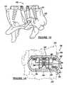
- the instrument assembly of the inventionis shown in figs. 11 and 12 .
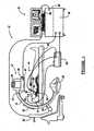
- Figure 1is a diagram of a navigation system employing a display
- Figures 2a and 2bare diagrams representing undistorted and distorted views of a fluoroscopic C-arm imaging device
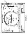
- Figures 3a and 3bis a logic block diagram illustrating a method for employing the display
- Figures 4a-4eillustrate a medical procedure employing the display
- Figure 5is a figure of the display
- Figure 6is a split screen view of the display
- Figure 7is an additional split screen view of the display
- FIGS 8a-8gillustrate another medical procedure employing the display
- Figure 9is an illustration of a dual display
- Figure 10is a logic block diagram illustrating a method for pre-operative planning and post-operative exam and tuning of an implant
- Figure 11is a perspective view of a platform and jig according to the invention, used in a minimally invasive surgical navigation spinal procedure;
- Figure 12is a perspective view of the jig that is operable to be attached to the platform of Figure 11 ;
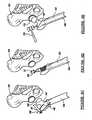
- Figure 13is a side view of a cervical disc implant having a minimally invasive adjustment mechanism
- Figure 14is a side view of a cervical disc implant having a telemetric adjustment mechanism
- Figure 15illustrates an implant of Figures 14 and 15 implanted into a spine
- Figure 16is a side cross-sectional view of a cervical disc implant
- Figures 16a-16care an unfolded and partially folded view of other embodiment of a cervical disc implant
- Figure 17is a side cross-sectional view of another cervical disc implant
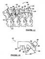
- Figure 18illustrates a cervical disc system employing multiple cervical disc implants
- Figure 19illustrates a transmit/receive module used during the motion analysis study of a patient.
- Figure 20illustrates a home based transmit/receive module used for a motion analysis study.
- Figure 1is a diagram illustrating a five or six degree of freedom (5 or 6 DOF) alignment display 10 employed with an image guided navigation system 12 for use in navigating a surgical instrument or implant during a medical procedure.
- the navigation system 12may be used to navigate any type of instrument or delivery system, such as a reamer, impactor, cutting block, saw blade, catheter, guide wires, needles, drug delivery systems, and cell delivery systems.
- the navigation system 12may also be used to navigate any type of implant including orthopedic implants, spinal implants, cardiovascular implants, neurovascular implants, soft tissue implants, or any other devices implanted in a patient 14.
- the navigation system 12may also be used to navigate implants or devices that are formed as an assembly or from multiple components where the location and orientation of each component is dependent upon one another to be effective in its use.
- the displaymay be used to track and align a spinal screw with a spinal rod to insure attachment of each device.
- the navigation system 12includes an imaging device 16 that is used to acquire pre-operative or real-time images of the patient 14.
- the imaging device 16is a fluoroscopic C-arm x-ray imaging device that includes a C-arm 18, an x-ray source 20, an x-ray receiving section 22, an optional calibration and tracking target 24 and optional radiation sensors 26.
- the optional calibration and tracking target 24includes calibration markers 28 (see Figures 2a-2b ), further discussed herein.
- a C-arm controller 30captures the x-ray images received at the receiving section 22 and stores the images for later use.
- the C-arm controller 30may also control the rotation of the C-arm 18.
- the C-arm 18may move in the direction of arrow 32 or rotate about the long axis of the patient 14, allowing anterior or lateral views of the patient 14 to be imaged. Each of these movements involve rotation about a mechanical axis 34 of the C-arm 18.
- the long axis of the patient 14is substantially in line with the mechanical axis 34 of the C-arm 18. This enables the C-arm 18 to be rotated relative to the patient 14, allowing images of the patient 14 to be taken from multiple directions or about multiple planes.
- An example of a fluoroscopic C-arm x-ray imaging device 16is the "Series 9600 Mobile Digital Imaging System," from OEC Medical Systems, Inc., of Salt Lake City, Utah.
- Other exemplary fluoroscopesinclude bi-plane fluoroscopic systems, ceiling fluoroscopic systems, cath-lab fluoroscopic systems, fixed C-arm fluoroscopic systems, etc.
- the imaging device 16generates x-rays from the x-ray source 20 that propagate through the patient 14 and calibration and/or tracking target 24, into the x-ray receiving section 22.
- the receiving section 22generates an image representing the intensities of the received x-rays.
- the receiving section 22includes an image intensifier that first converts the x-rays to visible light and a charge coupled device (CCD) video camera that converts the visible light into digital images.
- CCDcharge coupled device
- Receiving section 22may also be a digital device that converts x-rays directly to digital images, thus potentially avoiding distortion introduced by first converting to visible light. With this type of digital C-arm, which is generally a flat panel device, the calibration and/or tracking target 24 and the calibration process discussed below may be eliminated.
- the calibration processmay be eliminated for different types of medical procedures.
- the imaging device 16may only take a single image with the calibration and tracking target 24 in place. Thereafter, the calibration and tracking target 24 may be removed from the line-of-sight of the imaging device 16.
- Two dimensional fluoroscopic images taken by the imaging device 16are captured and stored in the C-arm controller 30. These images are forwarded from the C-arm controller 30 to a controller or work station 36 having the display 10 that may either include a single display 10 or a dual display 10 and a user interface 38.
- the work station 36provides facilities for displaying on the display 10, saving, digitally manipulating, or printing a hard copy of the received images, as well as the five or six degree of freedom display.
- the user interface 38which may be a keyboard, joy stick, mouse, touch pen, touch screen or other suitable device allows a physician or user to provide inputs to control the imaging device 16, via the C-arm controller 30, or adjust the display settings, such as safe zones of the display 10, further discussed herein.
- the work station 36may also direct the C-arm controller 30 to adjust the rotational axis 34 of the C-arm 18 to obtain various two-dimensional images along different planes in order to generate representative two-dimensional and three-dimensional images.
- the radiation sensors 26sense the presence of radiation, which is forwarded to the C-arm controller 30, to identify whether or not the imaging device 16 is actively imaging. This information is also transmitted to a coil array controller 48, further discussed herein.
- a person or physicianmay manually indicate when the imaging device 16 is actively imaging or this function can be built into the x-ray source 20, x-ray receiving section 22, or the control computer 30.
- Fluoroscopic C-arm imaging devices 16 that do not include a digital receiving section 22generally require the calibration and/or tracking target 24. This is because the raw images generated by the receiving section 22 tend to suffer from undesirable distortion caused by a number of factors, including inherent image distortion in the image intensifier and external electromagnetic fields.
- An empty undistorted or ideal image and an empty distorted imageare shown in Figures 2a and 2b , respectively.
- the checkerboard shape, shown in Figure 2arepresents the ideal image 40 of the checkerboard arranged calibration markers 28.
- the image taken by the receiving section 22, however,can suffer from distortion, as illustrated by the distorted calibration marker image 42, shown in Figure 2b .
- Intrinsic calibrationwhich is the process of correcting image distortion in a received image and establishing the projective transformation for that image, involves placing the calibration markers 28 in the path of the x-ray, where the calibration markers 28 are opaque or semi-opaque to the x-rays.
- the calibration markers 28are rigidly arranged in pre-determined patterns in one or more planes in the path of the x-rays and are visible in the recorded images. Because the true relative position of the calibration markers 28 in the recorded images are known, the C-arm controller 30 or the work station or computer 36 is able to calculate an amount of distortion at each pixel in the image (where a pixel is a single point in the image).
- the computer or work station 36can digitally compensate for the distortion in the image and generate a distortion-free or at least a distortion improved image 40 (see Figure 2a ).
- exemplary methods for performing intrinsic calibrationare described in the references: B. Schuele, et al., "Correction of Image Intensifier Distortion for Three-Dimensional Reconstruction," presented at SPIE Medical Imaging, San Diego, California, 1995 ; G. Champleboux, et al., "Accurate Calibration of Cameras and Range Imaging Sensors: the NPBS Method," Proceedings of the IEEE International Conference on Robotics and Automation, Nice, France, May, 1992 ; and U.S. Patent No. 6,118,845 , entitled “System And Methods For The Reduction And Elimination Of Image Artifacts In The Calibration Of X-Ray Imagers,” issued September 12, 2000.
- fluoroscopic C-arm imaging device 16is shown in Figure 1 , any other alternative imaging modality may also be used or an image-less based application may also be employed, as further discussed herein.
- CTcomputed tomography
- MSCTmulti-slice computed tomography
- MRImagnetic resonance imaging
- HIFUhigh frequency ultrasound
- OCToptical coherence tomography
- IVUSintra-vascular ultrasound
- 2D, 3D or 4D ultrasoundintraoperative CT,
- Image datasets from hybrid modalitiescould also provide functional image data superimposed onto anatomical data to be used to confidently reach target sights within the areas of interest.
- PETpositron emission tomography
- SPECTsingle photon emission computer tomography
- the fluoroscopic C-arm imaging device 16provides a virtual bi-plane image using a single-head C-arm fluoroscope 16 by simply rotating the C-arm 18 about at least two planes, which could be orthogonal planes to generate two-dimensional images that can be converted to three-dimensional volumetric images that can be displayed on the six degree of freedom display 10.
- the navigation system 12further includes an electromagnetic navigation or tracking system 44 that includes a transmitter coil array 46, the coil array controller 48, a navigation probe interface 50, an instrument 52 having an electromagnetic tracker and a dynamic reference frame 54.
- an electromagnetic navigation or tracking system 44that includes a transmitter coil array 46, the coil array controller 48, a navigation probe interface 50, an instrument 52 having an electromagnetic tracker and a dynamic reference frame 54.
- the entire tracking system 44 or parts of the tracking system 44may be incorporated into the imaging device 16, including the work station 36 and radiation sensors 26. Incorporating the tracking system 44 will provide an integrated imaging and tracking system. Any combination of these components may also be incorporated into the imaging system 16, which again can include a fluoroscopic C-arm imaging device or any other appropriate imaging device. Obviously, if an image-less procedure is performed, the navigation and tracking system 44 will be a stand alone unit.
- the transmitter coil array 46is shown attached to the receiving section 22 of the C-arm 18. However, it should be noted that the transmitter coil array 46 may also be positioned at any other location as well, particularly if the imaging device 16 is not employed. For example, the transmitter coil array 46 may be positioned at the x-ray source 20, within the OR table 56 positioned below the patient 14, on siderails associated with the OR table 56, or positioned on the patient 14 in proximity to the region being navigated, such as by the patient's pelvic area.
- the transmitter coil array 46includes a plurality of coils that are each operable to generate distinct electromagnetic fields into the navigation region of the patient 14, which is sometimes referred to as patient space. Representative electromagnetic systems are set forth in U.S. Patent No. 5,913,820 , entitled “Position Location System," issued June 22, 1999 and U.S. Patent No. 5,592,939 , entitled “Method and System for Navigating a Catheter Probe,” issued January 14, 1997.
- the transmitter coil array 46is controlled or driven by the coil array controller 48.
- the coil array controller 48drives each coil in the transmitter coil array 46 in a time division multiplex or a frequency division multiplex manner. In this regard, each coil may be driven separately at a distinct time or all of the coils may be driven simultaneously with each being driven by a different frequency.
- electromagnetic fieldsare generated within the patient 14 in the area where the medical procedure is being performed, which is again sometimes referred to as patient space.
- the electromagnetic fields generated in the patient spaceinduces currents in sensors 58 positioned in the instrument 52, further discussed herein. These induced signals from the instrument 52 are delivered to the navigation probe interface 50 and subsequently forwarded to the coil array controller 48.
- the navigation probe interface 50provides all the necessary electrical isolation for the navigation system 12.
- the navigation probe interface 50also includes amplifiers, filters and buffers required to directly interface with the sensors 58 in instrument 52.
- the instrument 52may employ a wireless communications channel as opposed to being coupled directly to the navigation probe interface 50.
- the instrument 52is equipped with at least one, and may include multiple localization sensors 58.
- the instrument 52may include an orthogonal pair coil sensor 58 or a tri-axial coil sensor 58 or multiple single coil sensors 58 positioned about the instrument 52.
- the instrument 52may be any type of medical instrument or implant.
- the instrumentmay be a catheter that can be used to deploy a medical lead, be used for tissue ablation, or be used to deliver a pharmaceutical agent.
- the instrument 52may also be an orthopedic instrument, used for an orthopedic procedure, such as reamers, impactors, cutting blocks, saw blades, drills, etc.
- the instrument 52may also be any type of neurovascular instrument, cardiovascular instrument, soft tissue instrument, etc.
- the instrument 52may be an implant that is tracked, as well as any other type of device positioned and located within the patient 14.
- implantscan include orthopedic implants, neurovascular implants, cardiovascular implants, soft tissue implants, or any other devices that are implanted into the patient 14.
- implantsthat are formed from multiple components where the location and orientation of each component is dependent upon the location and orientation of the other component, such that each of these components can be tracked or navigated by the navigation and tracking system 44 to be displayed on the six degree of freedom display 10.
- the electromagnetic sources or generatorsmay be located within the instrument 52 and one or more receiver coils may be provided externally to the patient 14 forming a receiver coil array similar to the transmitter coil array 46.
- the sensor coils 58would generate electromagnetic fields, which would be received by the receiving coils in the receiving coil array similar to the transmitter coil array 46.
- Other types of localization or trackingmay also be used with other types of navigation systems, which may include an emitter, which emits energy, such as light, sound, or electromagnetic radiation, and a receiver that detects the energy at a position away from the emitter. This change in energy, from the emitter to the receiver, is used to determine the location of the receiver relative to the emitter.
- localization systemsinclude conductive, active optical, passive optical, ultrasound, sonic, electromagnetic, etc.
- An additional representative alternative localization and tracking systemis set forth in U.S. Patent No. 5,983,126 , entitled “Catheter Location System and Method,” issued November 9, 1999.
- the localization systemmay be a hybrid system that includes components from various systems.
- the dynamic reference frame 54 of the electromagnetic tracking system 44is also coupled to the navigation probe interface 50 to forward the information to the coil array controller 48.
- the dynamic reference frame 54is a small magnetic field detector or any other type of detector/transmitter that is designed to be fixed to the patient 14 adjacent to the region being navigated so that any movement of the patient 14 is detected as relative motion between the transmitter coil array 46 and the dynamic reference frame 54. This relative motion is forwarded to the coil array controller 48, which updates registration correlation and maintains accurate navigation, further discussed herein.
- the dynamic reference frame 54can be configured as a pair of orthogonally oriented coils, each having the same center or may be configured in any other non-coaxial coil configuration.
- the dynamic reference frame 54may be affixed externally to the patient 14, adjacent to the region of navigation, such as the patient's spinal region, as shown in Figure 1 or on any other region of the patient.
- the dynamic reference frame 54can be affixed to the patient's skin, by way of a stick-on adhesive patch.
- the dynamic reference frame 54may also be removably attachable to fiducial markers 60 also positioned on the patient's body and further discussed herein.
- the dynamic reference frame 54may be internally attached, for example, to the spine or vertebrae of the patient using bone screws that are attached directly to the bone. This provides increased accuracy since this will track any motion of the bone.
- multiple dynamic reference frames 54may also be employed to track the position of two bones relative to a joint. For example, one dynamic reference frame 54 may be attached to a first vertebra, while a second dynamic reference frame 54 may be attached to a second vertebra. In this way, motion of the spine or vertebrae may be detected by the dual dynamic reference frames 54.
- An exemplary dynamic reference frame 54 and fiducial marker 60is set forth in U.S. Patent No. 6,381,485 , entitled "Registration of Human Anatomy Integrated for Electromagnetic Localization,” issued April 30, 2002.
- the navigation system 12operates as follows.
- the navigation system 12creates a translation map between all points in the radiological image generated from the imaging device 16 and the corresponding points in the patient's anatomy in patient space. After this map is established, whenever a tracked instrument 52 is used, the work station 36 in combination with the coil array controller 48 and the C-arm controller 30 uses the translation map to identify the corresponding point on the pre-acquired image, which is displayed on display 10. This identification is known as navigation or localization. An icon representing the localized point or instrument is shown on the display 10, along with five or six degrees of freedom indicia.
- the navigation system 12will detect both the position of the patient's anatomy 14 and the position of the surgical instrument 52. Knowing the location of these two items allows the navigation system 12 to compute and display the position of the instrument 52 in relation to the patient 14.
- the tracking system 44is employed to track the instrument 52 and the anatomy simultaneously. While the display 10 is configured to show the instrument with six degree of freedom accuracy.
- the tracking system 44essentially works by positioning the transmitter coil array 46 adjacent to the patient space to generate a low-energy magnetic field generally referred to as a navigation field. Because every point in the navigation field or patient space is associated with a unique field strength, the electromagnetic tracking system 44 can determine the position of the instrument 52 by measuring the field strength at the sensor 58 location.
- the dynamic reference frame 54is fixed to the patient 14 to identify the location of the patient 14 in the navigation field.
- the electromagnetic tracking system 44continuously recomputes the relative position of the dynamic reference frame 54 and the instrument 52 during localization and relates this spatial information to patient registration data to enable image guidance of the instrument 52 within the patient 14.
- Patient registrationis the process of determining how to correlate the position of the instrument 52 on the patient 14 to the position on the diagnostic, pre-acquired, or real-time images.
- the physician or userwill select and store particular points from the pre-acquired images and then touch the corresponding points on the patient's anatomy with a pointer probe 62.
- the navigation system 12analyzes the relationship between the two sets of points that are selected and computes a match, which correlates every point in the image data with its corresponding point on the patient's anatomy or the patient space.
- the points that are selected to perform registrationare the fiducial arrays or landmarks 60. Again, the landmarks or fiducial points 60 are identifiable on the images and identifiable and accessible on the patient 14.
- the landmarks 60can be artificial landmarks 60 that are positioned on the patient 14 or anatomical landmarks 60 that can be easily identified in the image data.
- the system 12may also perform 2D to 3D registration by utilizing the acquired 2D images to register 3D volume images by use of contour algorithms, point algorithms, normalized mutual information, pattern intensity, or density comparison algorithms, as is known in the art.
- the navigation system 12continuously tracks the position of the patient 14 during registration and navigation. This is necessary because the patient 14, dynamic reference frame 54, and transmitter coil array 46 may all move during the procedure, even when this movement is not desired. Therefore, if the navigation system 12 did not track the position of the patient 14 or area of the anatomy, any patient movement after image acquisition would result in inaccurate navigation within that image.
- the dynamic reference frame 54allows the electromagnetic tracking device 44 to register and track the anatomy. Because the dynamic reference frame 54 is rigidly fixed to the patient 14, any movement of the anatomy or the transmitter coil array 46 is detected as the relative motion between the transmitter coil array 46 and the dynamic reference frame 54. This relative motion is communicated to the coil array controller 48, via the navigation probe interface 50, which updates the registration correlation to thereby maintain accurate navigation.
- each vertebramay be independently tracked and the corresponding image registered to each vertebra.
- each vertebrawould have its own translation map between all points in the radiological image and the corresponding points in the patient's anatomy in patient space in order to provide a coordinate system for each vertebra being tracked.
- the tracking system 44would track any motion in each vertebra by use of a tracking sensor 58 associated with each vertebra.
- dual displays 10may be utilized, further discussed herein, where each display tracks a corresponding vertebra using its corresponding translation map and a surgical implant or instrument 52 may be registered to each vertebra and displayed on the display 10 further assisting an alignment of an implant relative to two articulating or movable bones. Moreover, each separate display in the dual display 10 may superimpose the other vertebra so that it is positioned adjacent to the tracked vertebra thereby adding a further level of information on the six degree of freedom display 10.
- the five or six degree of freedom alignment display 10can be used in an imageless manner without the imaging system 16.
- the navigation and tracking system 44may only be employed and the probe 62 may be used to contact or engage various landmarks on the patient. These landmarks can be bony landmarks on the patient, such that upon contacting a number of landmarks for each bone, the workstation 36 can generate a three-dimensional model of the bones. This model is generated based upon the contacts and/or use of atlas maps.
- the workstation 36may also generate a center axis of rotation for the joint or planes, based upon the probe contacts.
- the tracking sensor 58may be placed on the patient's anatomy and the anatomy moved and correspondingly tracked by the tracking system 44.
- placing a tracking sensor 58 on the femur and fixing the pelvis in place of a patient and rotating the leg while it is tracked with the tracking system 44enables the work station 36 to generate a center of axis of the hip joint by use of kinematics and motion analysis algorithms, as is known in the art.
- another tracking sensor 58may be placed on the pelvis to identify the center of axis of the hip joint.
- a tracking sensor 58is placed on the femur and a tracking sensor 58 is placed on the tibia, upon moving this portion of the anatomy, a center of axis of the knee joint may be identified. Likewise, by placing a separate tracking sensor 58 on two adjacent vertebra and articulating the spine, the center of axis of the spinal region can also be identified. In this way, a target and/or model based on the center of the particular joint may be designated and identified on the six degree of freedom display 10. Movement of the instrument or implant 52 may then be tracked in relation to this target and/or model to properly align the instrument or implant 52 relative to the target and/or model.
- the method 64begins by determining whether an image based medical procedure will be employed or an image-less medical procedure will be employed. If the image based procedure is being employed, the method proceeds along the first branch. In this regard, when an image based procedure will be utilized, the method begins at block 66 identifying the image tracking procedure. From block 66, the method proceeds to block 68 where images are generated by the imaging system 16. This imaging is performed at the area of interest of the patient 14 by any type of imaging device as previously discussed. Once images have been generated at block 68, the method proceeds to block 70 where calibration and registration is performed. In block 70, calibration of the imaging device 16 takes place using the calibration targets 28.
- registration of the pre-acquired images from block 68are registered to the patient space of the medical procedure utilizing the fiducial markers 60 and probe 62 as previously discussed. This registration registers the current patient space with the pre-acquired image, so that the instrument 52 or other devices may be tracked during the medical procedure and accurately superimposed over the pre-acquired images generated from the imaging device 16.
- the methodbegins at block 72 identifying that an image-less based medical procedure will be performed. This method proceeds to either block 74 identifying a first way to generate image-less models or block 76 identifying a second way to generate image-less models.
- the probe 62is used to contact the body at various anatomical landmarks in the area of interest, such as a bone. For example, by touching the probe 62 to the pelvis, knee, and ankle, articulation planes can be defined using known algorithms and the center of each joint may also be defined. An example of this type of modeling is set forth in U.S. Patent No. 5,682,886 . Alternatively, multiple anatomical landmarks can be contacted with the probe 62 to generate a 3-D model with the more points contacted, the more accurate the model depicted.
- a tracking deviceis placed on the body and the body rotated about the joint.
- the plane of rotation and joint centercan be identified using known kinematic and/or motion analysis algorithms or using atlas maps or tables, as is known in the art.
- a modelis generated at block 78.
- This modelcan be a 3-D surface rendered model, a 2-D model identifying articulating planes or a 3-D model identifying articulating planes and rotation, as well as the center of the joints. This enables the display 10 to use the joint centers or articulating planes as the target or trajectory, further discussed herein.
- the proceduremay be initially based on the use of atlas information or a 3-D model that is morphed, to be a patient specific model.
- an accurate representation of an ordinary femurmay be selected from an atlas map, thereby providing an initial 2-D or 3-D model representing a typical anatomical femur.
- the atlas modelmay be morphed into a patient specific 3-D model, with the more points contacted, the more accurate the morphed model.
- Patient specific informationmay also be acquired using an ultrasound probe to again identify the shape of the patient's natural femur in order to morph the atlas model.
- a fluoroscopic image of the regionmay also be used to morph the patient's femur with the atlas model to provide a patient specific morphed model.
- an atlas model of the femur and pelvismay be the initial starting point.
- a patient specific morphed modelmay be created to generate accurate joint centers and axes of motion again using known kinematics and/or motion analysis algorithms
- the methodproceeds to block 80.
- the specific type of coordinate systemis selected, which will be displayed by indicia on the six degree of freedom display 10.
- the coordinate systemscan be a Cartesian coordinate system, a spherical coordinate system, or a polar coordinate system.
- the Cartesian coordinate systemwill be selected.
- the Cartesian coordinate systemwill include the X, Y, and Z axes, and X rotation, Y rotation, and Z rotation about its respective axes.
- the six degree of freedom display 10is shown in further detail employing the Cartesian coordinate system.
- the X axis 82 and the Y axis 84are shown positioned on the display 10.
- the Z axis 86extends out from the display 10 and is shown in the upper left corner.
- Rotation about the X axisis shown by bar graph 88 to the right of the display 10 and rotation about the Y axis is shown by bar graph 90 positioned at the bottom of the display 10.
- Rotation about the Z axisis shown with the arcuate bar graph 92 oriented about the X and Y axes 82 and 84.
- Each axis, as well as the rotation axes identified by the bar graphsmay be color coded to identify safe zones or regions for the item being tracked or navigated.
- the safe zonescan be defined as ranges around the planned trajectory path or target where the safe zones are determined by manufactured determined parameters, user determined parameters or patient specific parameter, further discussed herein.
- Arrow indicator 94identifies the degree of rotation about the X axis 82.
- Arrow indicator 96shows the amount of rotation about the Y axis 84.
- Arrow 98identifies the rotation about the Z axis, while arrow 100 identifies the depth being tracked along the Z axis 86.
- the origin 102may be set to be the desired target position or trajectory path.
- the crosshairs 104represents the tip of the instrument 52 being tracked, while the circle 106 represents the hind area of the instrument 52 being tracked. With the understanding that the instrument 52 can be any type of medical device or implant. Also, if five degree of freedom information is provided, one of the indicia 82, 84, 86, 88, 90, and 92 will be removed.
- the methodproceeds to block 108 where the target or trajectory is selected.
- the target or trajectory selected at block 108is typically positioned at the origin 102 on the display 10. In this way, the object being tracked or aligned may be tracked and aligned about the origin 102.
- the targetmay be identified at any coordinate within the display 10 or multiple targets may also be identified within the single display 10.
- An indicia of the targetmay also be positioned on the display 10. The target is selected based upon the desired area to position the instrument 52 and can be selected from the pre-acquired images or from the 3-D model. Once selected, this target is correlated to the display 10 and generally positioned at the origin 102.
- the methodproceeds to block 110 where the safe zones are identified for each degree of freedom.
- the safe zones 112are identified for each degree of freedom by color coding.
- the safe zone 112 for the X axisis between -2.5 and +2.5.
- the safe zone 112 for rotation about the X axisis between -5° and +5° of rotation about the X axis.
- the usercan simply guide the instrument 52 using the cross hairs 104 and circle 106 to align the instrument 52 within these designated safe zones 112.
- these safe zones 112may be determined by manufacture specifications, such as tolerance range of the instruments or positions for implants.
- the safe zones 112may also be determined based on the patient, the surgeon conducting the procedure, or any other factors to assist a surgeon in navigating the instrument 52 through the patient 14. These safe zones 112 may also be identified via an audible signal or tone or a varying tone. The safe zones 112 may also be identified by any other convenient manner to be set out on the display 10.
- the methodproceeds to block 114 where the target trajectory in the selected coordinate system is displayed with the safe zones 112, as shown in Figure 5 .
- a decision whether to superimpose the image over the target/trajectoryis made.
- the imagemay be placed adjacent to the target trajectory display, as is shown in Figure 6 , and further discussed herein.
- this modelmay be superimposed over the target/trajectory display on display 10 or may be positioned adjacent to the target/trajectory display in a split screen or on a separate display.
- the methodproceeds to block 120 where the first implant/instrument 52 is tracked with the navigation system 44. With the implant/instrument 52 being tracked at block 120, the method proceeds to block 122 wherein indicia representing the implant/instrument 52 is displayed on the display 10, with either five or six degrees of freedom information.
- the indicia representing the implant/instrument 52is the crosshairs 104 and the circle 106 designating the tip and hind, respectively. The tip 104 and hind 106 is represented in relation to the target/trajectory path 102 in six degrees of freedom.
- This six degrees of freedominclude the X and Y locations, as well as the depth Z of the implant/instrument 52 displayed.
- the rotation about each of the axesis also provided. This rotation can be helpful in many applications, including orthopedic, where rotation specific components need to be positioned relative to one another. For example, in a spinal application, alignment of a pedicle screw in relation to a spinal rod, would require information regarding the rotation of the screw relative to the rod. In cardiac procedures, this may be useful where ablation is necessary on a certain side of an artery and the ablation electrode is only positioned on one side of the catheter. In this situation, rotation of the catheter relative to the target in the artery is critical.
- a biopsy needlemay only have a biopsy port positioned upon one portion of the circumference of the needle, thereby requiring the rotation of the biopsy needle to be known in order to provide the proper capture of the relevant biopsy sample. Without this display, this information would not be available.
- the implant/instrument 52is aligned or fixed with the target/trajectory 102 at block 124.
- the tip 104 and the hind 106are aligned and fixed relative to the target/trajectory 102 at the origin and the rotational orientation is also aligned to the desired position.
- the target/trajectory 102may not be positioned at the origin and can be positioned anywhere within the coordinate system if desired.
- the tip 104 of the implant/instrument 52is shown aligned with the target 102, while the hind 106 is slightly offset from the target/trajectory 102.
- this offset from the target/trajectory 102may affect the second implant, which possibly articulates or mates with the first implant. If this is the case, the second target/trajectory 102 will need to take into consideration this offset in order to provide proper articulation and alignment of the first implant component with the second implant component.
- the implantmay also have numerous components with each component articulating or mating with another component, thereby requiring tracking of each component as it is implanted during the minimally invasive procedure.
- This second target/trajectory 102may be displayed on a separate display 10 (see Figure 1 ), positioned via a split screen of a single display 10 or may be superimposed upon the existing display that displays the first target 102 and implant position. In this way, orientation and placement of both the first and second implants, which are dependent upon one another can be shown in the display 10 providing the surgeon the opportunity to adjust either position of either implant intraoperatively before the implants are permanently affixed to the patient 14.
- These types of implantsinclude knee implants, hip implants, shoulder implants, spinal implants, or any other type of implant, which has a bearing surface and an articulating surface or any type of implant having multiple mating and connecting components.
- the methodproceeds to block 132.
- the safe zones 112 for each degree of freedomis selected for the second implant/instrument 52 similar to the way the first set of safe zones 112 were selected for the first implant/instrument 52.
- the methodproceeds to block 134.
- the display 10displays the second target/trajectory 102 in the same coordinate system with the second safe zones 112.
- the pre-acquired imagemay be superimposed on to the target/trajectory 102. Alternatively, this image can be positioned adjacent the target screen in a split screen configuration (see Figure 6 and 7 ).
- the surgical implant/instrument 52is tracked at block 140.
- the second implant/instrument 52can be tracked on a separate display 10 or be tracked on the same display as the first implant/instrument 52.
- separate displays 10may be used where information is linked between the displays showing the second implant/instrument 52 in relation to the first implant/instrument 52.
- the second implant/instrument 52With the second implant/instrument 52 being tracked at block 140, the second implant/instrument 52 is displayed in relation to the second target/trajectory 102 in five or six degrees of freedom at block 142.
- thismay be a separate display 10, a split screen display 10 with both the first target/trajectory 102 and the second target/trajectory 102 or the same display 10 displaying both targets/trajectories 102.
- the second implant/instrument 52is being displayed, the second implant/instrument 52 is aligned and fixed at the second target/trajectory 102 at block 144. Once the second implant/instrument 52 is fixed at block 144, the method proceeds to block 146.
- a surgeoncan determine whether each implant/instrument 52 is within its desired safe zones 112 and, therefore, optimally positioned for proper articulation.
- these safe zones 112may be color coded for the different safe zones provided. If both implants are positioned and fixed at the proper targets, the method ends at block 148. If one or both of the implants are not properly positioned, adjustment of the first or second target/trajectory 102 is performed at block 150.
- the six degree of freedom display 10may be used to track other medical devices as well.
- an ablation cathetergenerally has an electrode positioned only on one angular portion of its circumference.
- the wall of an arterytypically has a larger plaque build-up on one side. Therefore, it is desirable to align that ablation electrode with the proper side of the artery wall during the procedure.
- the surgeoncan easily identify the location, depth and angular rotation of the catheter relative to the artery wall.
- Other types of proceduresmay require the medical instrument or probe to be properly oriented and located within the patient, such as identifying and tracking tumors, soft tissue, etc.
- the implant/instrument 52have a tracking sensor associated therewith in order to identify the location of the tracked device in six degrees of freedom and display it on the display 10.
- the tracking sensorsmay be attached directly to implants, attached to the instruments that engage the implants or attach to members extending out from the implants.
- These tracking sensorsagain may be electromagnetic tracking sensors, optical tracking sensors, acoustic tracking sensors, etc.
- targetswhich may or may not be superimposed on the display again include orthopedic targets, spinal targets, cardiovascular targets, neurovascular targets, soft tissue targets, etc. Specific examples include again the location of the plaque on a wall of an artery, the center of an articulating joint being replaced, the center of the implant placement, etc.
- the surgeoncan dynamically plan and trial implant placements by moving one component of the implant to see where the other articulating component of the implant should be positioned. In this way, the surgeon can trial the implant confirming its placement and orientation, via the display 10 before the implant is permanently affixed to the patient 14.
- two adjacent vertebra bodiescan be tracked and displayed on two separate displays.
- a single jigsuch as a cutting jig is used to cut both the surface of the first vertebra and the surface of the second vertebra
- orientation of the jigmay be displayed on each separate display in relation to the corresponding vertebra being acted upon, thereby enabling simultaneous tracking of the two planes being resected for each separate vertebra on a dual display system.
- each vertebramay be displayed on each of the dual displays so that the vertebra being tracked is shown with the adjacent vertebra superimposed adjacent thereto.
- the methoddemonstrates that the display 10 illustrated both the position and orientation of an object with respect to a desired position and orientation with six degrees of freedom accuracy.
- the display 10may be automatically updated in real-time using the navigation system 44 to report the orientation of the tracked device.
- the usermay also adjust the display 10 in order to control a device's orientation.
- the display 10again consists of three rotational indicators (RX, RY, RZ) and three translational indicators or indicia (TX, TY, TZ).
- Each indicatorshows both visual and quantitative information about the orientation of the device.
- Each indicatoralso displays a predetermined safe zone 112 and application-specific label for each degree of freedom.
- itmay also be relevant to overlay the display 10 over anatomical image data from the imaging device 16.
- the anatomy normal to the tip 104 of the positioned devicecan provide the user with additional positional information.
- Tones, labels, colors, shading, overlaying with image datacan all be modified and incorporated into the display 10.
- the current display 10is also shown as a Cartesian coordinate based display, but again could be based on a polar based display or a spherical based display and a quick switch between both can be supplied or simultaneously displayed.
- the displaycan also be configured by the user to hide parameters, location, size, colors, labels, etc.
- Some medical applicationsthat may be commonly displayed and linked to the display 10 are: 1) reaming of an acetabular cup with major focus upon RY and RZ, 2) length of leg during hip and knee procedures focused upon TZ and RZ, 3) biopsies and ablations focused upon RX, RY, and RZ for direction of the therapy device, and 4) catheters with side ports for sensing information or delivery of devices, therapies, drugs, stem cells, etc. focused upon six degree of freedom information.
- FIG. 4a - 4ea medical procedure employing a six degree of freedom alignment display 10 is shown in further detail.
- an orthopedic medical procedure replacing the hip jointis illustrated.
- various instruments 52, as well as the implants 52are tracked and aligned using the six degree of freedom display 10.
- a femur 160 having a femoral head 162is illustrated, along with a pelvis 164 having an acetabulum 166.
- this area of interestwill be imaged by the imaging device 16.
- the dynamic reference frame 54may be attached to the femur 154 or the pelvis 164 or two dynamic frames 54 may be attached, one to each bone to provide additional accuracy during the medical procedure.
- a center of articulation of the acetabulum 166is identified as the target 168, shown in Figure 6 .
- Figure 6illustrates the display 10 configured as a split screen with the right identifying the six degree of freedom display and the left illustrating the pre-acquired image with the center of articulation 168 being the intersection of the X, Y, and Z axes.
- a reamer 170 having a tracking sensor 58is shown reaming the acetabulum 166.
- the tracking system 44is able to accurately identify the navigation of the tip and hind of the reamer 170.
- an acetabular cup 178is shown being impacted into the reamed acetabulum 166, via the tracked guide tool 180 with an impactor 182.
- the guide tool 180has a distal end, which is nestingly received within the acetabular cup 178.
- orientation of the acetabular cup 178may be displayed on the display 10 in six degrees of freedom.
- the surgeoncan view on the display 10 whether the acetabular cup 178 is properly positioned at the proper angular orientation, as shown in Figure 7 , the impactor 180 is shown superimposed over an image generated by the imaging device 16. In this way, the proper orientation, including abduction and anteversion is achieved before the acetabular cup 178 is permanently implanted.
- the femoral head 162is resected along a plane 184 by use of a cutting guide 186, having the tracking sensor 58 and a saw blade 188.
- the cutting plane 184may be properly defined to provide proper articulation with the acetabular cup 178 before a hip stem is implanted in the femur 160.
- the second targetis dependent upon the first target.
- the second targetmay be properly compensated to accommodate for this offset by use of the display 10.
- a second display illustrating the target for the cutting plane 184may be provided.
- a reamer 190is employed to ream out the intramedullary canal 192 of the femur 160.
- a subsequent targetcan be defined and identified on the display 10 and tracked by use of the tracking sensor 58. This target may be displayed separately or in combination with the previously acquired targets.
- a hip stem 194is impacted with an impactor 196 into the intramedullary canal 192.
- an impactor 196By targeting the acetabular cup location, along with the resection plane 184 and the reaming axis of the reamer 190, upon positioning the hip stem 194, within the femur 160, proper articulation and range of motion between the acetabular cup 178 and the hip stem 194 is achieved without time consuming trialing as is conducted in conventional orthopedic procedures.
- the six degree of freedom display 10may be utilized with any type of medical procedure requiring visualization of a medical device with six degree freedom information.
- the six degree of freedom display 10enables implants, devices and therapies that have a specific orientation relative to the patient anatomy 14 to be properly positioned by use of the display 10. As was noted, it is difficult to visualize the correct placement of devices that require five or six degree of freedom alignment. Also, the orientation of multiple-segment implants, devices, or therapies in five and six degrees of freedom so that they are placed or activated in the correct orientation to one another is achieved with the display 10. Since the location and orientation is dependent upon one another to be effective, by having the proper orientation, improved life of the implants, the proper degrees of motion, and patient outcome is enhanced. Also, the six degree of freedom display 10 may be used as a user input mechanism by way of keyboard 38 for controlling each degree of freedom of a surgical robotic device.
- the usercan input controls with the joystick, touch screen or keyboard 38 to control a robotic device.
- These devicesalso include drill guide holders, drill holders, mechanically adjusted or line devices, such as orthopedic cutting blocks, or can be used to control and drive the alignment of the imaging system 16, or any other type of imaging system.
- the display 10may include a stereo display or two displays 10. These displays may or may not be linked, depending on the certain procedure.
- the target point/locationtranslation and orientation of each implant component is dependent upon the other implant placement or location). Therefore, the adjustment or dynamic targeting of the dependent implant needs to be input to the dependent implant and visually displayed. Again, this can be done by two separate displays or by superimposing multiple targets on a single display.
- Many implantssuch as spinal disc implants, total knee and total hip replacements repair patient anatomy 14 by replacing the anatomy (bone, etc.) and restoring the patient 14 to the original biomechanics, size and kinematics.
- the benefit of the six degree of freedom alignment display 10is that original patient data, such as the images can be entered, manually or collectively, via the imaging device 16 or image-less system used for placement of the implant. Again, manually, the user can enter data, overlay templates, or collect data, via the imaging system 16.
- An example, as discussed herein of an applicationis the alignment of a femoral neck of a hip implant in the previous patient alignment.
- the previous patient alignmentcan be acquired by landmarking the patient femoral head by using biomechanics to determine the center and alignment of the current line and angle of the femoral head. This information can be used as the target on the display 10 in order to properly align the implant replacing the femoral head.
- the six degree of freedom display 10also provides orientation guidance on a single display. Separate visual and quantitative read-outs for each degree of freedom is also displayed on the display 10. Visual representations or indicia of procedure-specific accepted values (i.e., a "safe zone 112") for each degree of freedom is also clearly displayed on the display 10. These safe zones 112 are displayed as specifics or ranges for the user to align or place within.
- the procedure specific accepted values for the safe zones 112can be manufacture determined, user determined, patient specific (calculated) or determined from algorithms (finite element analysis, kinematics, etc. atlas or tables). It can also be fixed or configurable. Safe zones 112 can also be defined as ranges around a planned trajectory path or the specific trajectory path itself (range zero). The trajectory paths are input as selected points by the user or paths defined from the patient image data (segmented vascular structure, calculated centers of bone/joints, anatomical path calculated by known computed methods, etc.).
- FIGs 8a-8ganother medical procedure that may employ the six degree of freedom alignment display 10 is shown in further detail, along with Figure 9 illustrating the use of the display 10 during this medical procedure.
- a spinal medical procedurethat implants a cervical disc implant between two vertebrae is illustrated.
- various instruments 52, as well as the implant 52are tracked and aligned using the six degree of freedom display 10.
- the bony structures during the procedureare also tracked.
- a first vertebra or vertebral body 200is shown positioned adjacent to a second vertebra or vertebral body 202 in the cervical area of the spine. Assuming that the medical procedure is being performed in an image based system, this area of interest would be imaged by the imaging device 16.
- a dynamic reference frame 54may be attached to the first vertebra 200 and a second dynamic reference frame 54 may be attached to the second vertebra 202.
- These dynamic reference frames 54may also be combined with tracking sensors 58, which are shown attached to the vertebral bodies 200 and 202.
- a center of articulation of the vertebra 200 and a center of articulation of a vertebra 202may be identified as the targets 168 on the dual display illustrated on Figure 9 .
- This center of articulation or instantaneous center of rotationis identified as the "X" along axis Y.
- a plane or axis Xis shown perpendicular to the longitudinal or spinal axis Y. This axis is where the implant, as well as milling should be performed or centered around.
- a cam distracter instrument 204is shown distracting the vertebra 200 relative to the vertebra 202.
- the cam distracter 204may be tracked, via another tracking sensor 58 affixed to the cam distracter 204.
- the six degree of freedom display 10 illustrated in Figure 9can illustrate a location of the cam distracter 204 relative to the center of each vertebra 200 and 202 independently on the display. Since the instrument 204 is rigid, by locating the tracking sensor 58 on the instrument 204, the distal end of the instrument 204 is known and may be illustrated on the display 10 using crosshairs 104 and circle 106 to represent the tip and hind, respectively.
- a sagittal wedge 206also having a tracking sensor 58 is utilized and shown in Figure 8c .
- the sagittal wedge 206is used to center each vertebrae 200 and 202, along the sagittal plane and again may be tracked and displayed with six degree of freedom on the display 10, as illustrated in Figure 9 .
- the surgeoncan confirm both visually and via the display 10 that the sagittal wedge 206 is centered on the sagittal plane between the vertebrae 200 and 202, as well as obtain the proper depth, via the Z axis display 86 on the display 10, illustrated in Figure 9 .
- a burr 208 attached to a burring hand piece 210is used to burr an area between the first vertebra 200 and the second vertebra 202.
- the orientation of the burr 208 relative to each vertebrae 200 and 202may be displayed on the display 10 with six degree of freedom information. Therefore, burring along the proper X and Y plane, as well as the proper depth may be visually displayed with the appropriate indicia, as illustrated in Figure 9 . Rotational information about the corresponding X, Y and Z axes is also displayed.
- each single display in the dual display 10may also superimpose an image of each vertebrae 200 and 202 relative to one another on the display with each display having its coordinate system referenced to one of the vertebrae.
- the resulting milled vertebrae 200 and 202are shown in Figure 8e with a ring portion 214 milled to receive the spinal implant 52.
- the spinal implant 52is shown being implanted between the vertebrae 200 and 202 using an implant inserter 216 that is also tracked by tracking sensor 58.
- the spinal implant 52may be any type of cervical or other spinal disc implant for any other area of the spine.
- the spinal implantmay be the spinal implant disclosed in U.S. Patent No. 5,674,296 , entitled “Human Spinal Disc Prosthesis,” issued October 7, 1997, U.S. Patent No.
- the anchors 220are optional since orientation of the implant 52 can be tracked continuously as it is inserted between the vertebrae 200 and 202. Here again, this eliminates the need for forming holes in the vertebrae 200 and 202.
- the implant 52 illustrated in these figuresis merely an exemplary type of spinal implant and any known spinal implants may also be similarly tracked.
- another common type of spinal implantis formed from a two-piece unit that includes a ball and cup articulating structure that may likewise be independently tracked to assure proper fit and placement.
- the six degree of freedom display 10which is illustrated as a split or dual display 10 in Figure 9 assists a surgeon in implanting a spinal implant 52 in order to achieve proper fixation and orientation of the implant 52, relative to two movable vertebrae 200 and 202.
- tracking each vertebra 200 and 202 independently, and tracking its resectionshould one vertebra be resected off-plane due to anatomical anomalies, adjustment of the plane at the adjacent vertebra may be achieved in order to still provide a proper fit for the spinal implant 52.
- each vertebrae 200 and 202can be independently monitored, so that if one is off axis, the other can be manipulated accordingly to account for this adjustment.
- further accuracywas achieved, thereby providing increased range of motion for the patient after implantation of the implant 52.
- the range of motionmay be increased while reducing impingement of two-part articulating or fixed implants. This also enables maximum force transfer between the implant and the body.
- therapy delivery proceduresby knowing the location of the catheter delivery tube and the specific port orientation, accurately aiming at the site is enabled to provide maximum delivery of the therapy at the correct site.
- This procedurealso enhances and enables better results when using an ablation catheter by again knowing the rotational orientation of the ablation catheter and the ablation electrode relative to the area in the wall of the artery that requires ablation.
- this type of cathetermay be easily directed and aligned to tumors, stem cells, or other desired sites in an easy and efficient manner.
- a method 230 for post-operative adjustment or tuning of implantssuch as a spinal implant is disclosed.
- the method 230also includes pre-operative planning, implanting, as well as the post-operative exam procedure.
- the method 230begins at block 232 where pre-operative planning of the medical procedure begins.
- the pre-operative planningproceeds from block 232 to either block 234 if an image based pre-operative plan is conducted or block 236 if both an image and sensing pre-operative plan is conducted. If an image based pre-operative plan is being conducted, the method proceeds to block 238 where pre-operative image data is acquired.
- the pre-operative imagesmay be captured from a four-dimensional CT scan, which provides for capturing images over a specific time frame.
- the patientmay be asked to move his or her neck in different manners to capture the image data over time.
- any other type of imaging device 16may be employed to either simply gather static image data or image data over time.
- the captured image datamay also be used in conjunction with the electromagnetic tracking system 44, as discussed herein.
- Another example of pre-operative planning using a tracking systemis disclosed in U.S. Patent No. 6,470,207 , entitled “Navigation Guidance Via Computer-Assisted Fluoroscopic Imaging," issued October 22, 2002. Other types of pre-operative planning using a tracking system may also be employed. This image data is then analyzed at the analysis data block 240, further discussed herein.
- this procedurewill capture image data and sense parameters at block 242.
- the captured image datamay be the same image data that is captured at block 238.
- various parameters in the area of interestmay also be sensed during the pre-operative planning state.
- probes or sensorsmaybe placed in the area of interest to sense the parameters, such as temperature, pressure, strain, and force motions.
- sensorsmay be positioned between adjacent vertebrae of interest to measure temperature in certain areas, which may indicate friction or impingement.
- strain gaugesmay be positioned to measure forces to identify areas having unacceptably high forces between the vertebrae. Again, this data is then analyzed at block 240.
- the data from either the image based or the image sense based pre-operative planningis analyzed. Should the data only include image data from block 238, this image data may be used to identify areas of interest, the patient size, and be used to assist in preparing the surgical plan. By viewing this data, such as 4D data, which is essentially 3D data over time or static image data, certain abnormal or irregular movements in the area of interest may be identified. These areas may be identified by visual examination, by performing finite element analysis or other known motion analysis to create a 3D model of the captured image. The finite element analysis may include calculating the instantaneous center of rotation "x" or make this determination from the image data itself.
- the overall shape of the spinemay also be analyzed via the image data to identify and determine various force vectors on the discs of interest by analyzing the entire spine, the curvature of the spine and the articulation area of the angle of the spine relative to the ground. This information may be used to find force vectors and loading on the various regions of the vertebrae of interest. Should the sensed parameters also be used, or alternatively only be used, these sensor readings, which can be measured statically or actively while the patient is moving are utilized to again identify points of interest or potential abnormal activities by sensing parameters, such as temperature, pressure, stress, and strain in the area of interest.
- the procedureproceeds to block 243, where the implant and the type of procedure is selected.
- the implantis selected, based on the various abnormalities identified in order to enable the surgeon to resolve the noted abnormalities.
- the implantis selected based on various parameters, such as material selection, performance characteristics, stiffness, style or implant type and sizing.
- sizing of the implantmay also be pre-operatively performed, based on the data captured and analyzed at block 240. Sizing may be performed using known sizing templates, which provides the surgeon with a visual means of correlating the size of the implant to the area of interest.
- various sized templates automated in softwaremay also be included and stored within the work station 36 and superimposed in the area of interest to provide a visual indication of the sized implant to select.
- the type of procedure to position the implantmay be determined pre-operatively.
- the procedureproceeds to block 244.
- the selected implantis implanted generally under surgical guidance in the area of interest.
- a cervical disc implantmay be implanted, as illustrated in Figures 8a-8g .
- any other type of implant proceduremay also be performed to position the selected implant, which may include a non-surgically guided procedure.
- Other exemplary types of surgically guided proceduresare set out in U.S. Patent No. 6,470,207 , entitled “Navigation Guidance Via Computer-Assisted Fluoroscopic Imaging," issued October 22, 2002; U.S. Patent No. 6,434,415 , entitled “System For Use in Displaying Images Of A Body Part," issued August 13, 2002; and U.S. Patent No. 5,592,939 , entitled “Method and System for Navigating a Catheter Probe,” issued January 14, 1997.
- the recovery periodwill vary depending on the type of procedure, the type of implant, the patient's medical history and age, and other variables.
- the area of abnormality surrounding the implantmay also heal and recover. For example, if a cervical disc was implanted, the muscular structure surrounding this area, which may have previously been overcompensating because of the abnormality may now have returned to a normal state. These surrounding structure changes, may affect the way the implant was positioned within the patient or the performance characteristics of the implant. In this regard, if the implant was positioned based upon abnormal surrounding structure, the implant may subsequently not provide the full range of motion as anticipated, thereby potentially resulting in further surgeries being required.
- the initially selected performance characteristics of the implantmay have changed to due subsequent healing or other actions, thereby rendering the initial performance characteristics inappropriate for the current patient's condition.
- These performance characteristicscan be any type of characteristics regarding the implant, including stiffness, actuation, loading, range of motion, etc.
- correctionsmay be made to compensate for any subsequent anomalies observed by the surgeon. Again, the anomalies may result from healing of surrounding tissue, incorrect initial placement, changes in performance characteristics, or any other reasons. It should also be pointed out that if undesirable performance characteristics result after healing, the surrounding tissue and discs may also be damaged or deteriorate, thereby compounding recovery time and maybe requiring additional implants. This is the reason that providing the proper performance characteristics after healing is so critical.
- a post-operative examis performed, exemplified at block 248.
- This post-operative exammay be conducted in different manners, depending upon the type of implant, the type of sensors and controls available with the implant, as well as the types of adjustments available with the implant.
- Some implantsmay have adjustment capabilities that require minimally invasive percutaneous type procedures, while other implants can be adjusted telemetrically or adaptively, as further discussed herein.
- the pre-operative exammay also be carried out using various types of equipment, again depending upon the capabilities of the implanted device, further discussed herein.
- the pre-operative examincludes a motion analysis study, represented by block 250.
- This motion analysis studygenerally involves articulating the area of interest to determine range of motion, strength, etc.
- the patient 14is typically put through various motion testing. This testing may include various calisthenics, treadmill performance, weight lifting, gate analysis, etc.
- the motion analysis 250can be performed and studied using an image-based procedure, set out at block 252, a sensor-based procedure, set out at block 254, or an image and sensor-based procedure, set out in block 256. It should also be pointed out that while block 250 is labeled motion analysis, the analysis can be performed via static image-based procedures or static sensor-based procedures, which are contemplated and included in the motion analysis study 250.
- the static image data or sensed datacan be obtained and reviewed, via the image-based block 252 or the sensor-based block 254 to determine if the performance characteristics have changed.
- the image-based proceduremay be performed by either employing a localization or navigation tracking system or capturing image data, such as 3D or 4D image data, by an imaging device, such as a 4D CT imaging device. Should the motion analysis study be performed using localization or navigation technology, capturing image data and registration is performed as disclosed herein.
- U.S. Patent No. 6,434,415entitled “System for Use in Displaying Images of a Body Part," issued August 13, 2002, also discloses pre-operative planning using navigation technology.
- pre-acquired image datamay be obtained, for example, in the cervical spinal region. Before this image data is obtained, fiducial markers and localization sensors may be attached to each vertebrae of interest.
- the patient 14may be positioned on a treadmill with the tracking system 44 placed in proximity to track the motion of each vertebrae.
- This motioncan include a gate analysis study of the patient's motion as well.
- the navigation space of the patient 14is registered to the pre-acquired images.
- tracking of the moving vertebraemay be captured and illustrated on a display, such as the display 10, or any other display.
- image datamay simply be captured over time during the motion analysis 250, for example, by the use of a four-dimensional CT scan.
- each individual vertebraemay be segmented out using known segmenting algorithms. These types of algorithms generally involve thresholding or templates, which will segment out each vertebra in the scan.
- finite element analysismay be performed using known finite element analysis. The finite element analysis may also be used to calculate the instantaneous center of rotation "x".
- the information gathered during motion analysis 250is used to determine the necessary adjustment of the implant at block 258. This information may include visualization of impinged areas around the implant, misalignment, etc.
- the sensor readings of various parametersare used to determine if there is any necessary adjustment, at block 258.
- the sensor based approachmay either take readings from sensors located within the implant or from sensors attached to the patient during this analysis.
- the sensorsmay take temperature readings, which can indicate potential friction and higher forces, strain or stress readings, as well as load readings or any other parameter readings. Again, this information is used at block 258 to determine the necessary adjustment to the implant.
- both an image and sensor-based motion analysismay be conducted. This analysis essentially combines the image data at block 252 and the sensor data at block 254 to perform the post-operative analysis of the patient. Again, this information is used at block 258 to determine any necessary adjustments of the implant.
- the sensed parametersmay be synchronized in time with the image data to provide information on when the sensed parameters were captured relative to the time and the image.
- the data captured during motion analysis 250is studied to determine whether any adjustments are necessary relative to the implant. For example, if a cervical disc was implanted and the patient healed and subsequent spinal alignment occurred, the range of motion may be compromised. In order to provide the proper range of motion, post-operative tuning of the implant may be necessary, based on the motion analysis study 250.
- the post-operative tuning of the implantmay also be necessary when the performance characteristics of the implant have changed.
- Performance characteristicsmay be selected, based on various criteria, such as when the patient is in a relatively static state, thus requiring certain performance characteristics, as compared to when the patient is in vigorous active state, where the performance characteristics must be changed.
- the spinal implantmay not need significant stiffness in a relatively static condition, while in very active condition, the spinal implant may require a stiffer cushioning.
- the performance characteristicmay have been selected when the patient was disabled, so that once the patient heals, the performance characteristics may have to be adjusted accordingly. This adjustment may be conducted using a minimally invasive adjustment procedure at block 260 or a telemetric adjustment procedure at block 262.
- percutaneous adjustment of the implantmay be performed by actuating various adjustment mechanisms within the implant, further discussed herein.
- adjustment screwsmay be positioned at hinge points within the implant and engaged by a driver in a minimally invasive type procedure to provide the proper adjustment, thereby reacquiring the proper range of motion, via adjusting the articulating surfaces of the implant.
- Adjustment of the performance characteristic, such as stiffnessmay also be performed, as further discussed herein.
- the implantmay be driven telemetrically, using known telemetric type wireless systems, such as that disclosed in U.S. Patent No. 6,474,341 , entitled "Surgical Communication Power System," issued November 5, 2002, or any other known wireless telemetric systems.
- the telemetric systemmay be an RF based or electromagnetic based telemetric system, as is known in the art.
- the implantmay be a passive or active battery powered device that includes motors, pumps or any other devices used to adjust the implant, further discussed herein.
- the procedureproceeds to block 264 where the adjustment is confirmed. If the adjustment is proper, the procedure ends at block 266. If not, further adjustments are performed.
- This pre-operative and post-operative procedureprovides better initial implantation accuracy and implant selection, as well as the opportunity for post-operative tuning or adjustment of the implant.
- the post-operative tuningenables adjustment of articulating surfaces, supports, or other parameters within the implant post-operatively without requiring revision surgery.
- an instrument assemblythat includes a mounting platform 268 and an attachment jig 270 for use in a surgical navigated spinal procedure is illustrated.
- the mounting platform 268is percutaneously attached to a series of vertebrae 272, via multiple K-wires 274.
- the mounting platform 268is positioned outside the patient's body and above the vertebrae 272 of interest.
- the mounting platform 268may be sized to span any number of vertebrae 272. In this example, four vertebrae 272 are spanned with the mounting platform 268 with the first and fourth vertebrae being secured to the mounting platform, via K-wires 274.
- the mounting platform 268is designed to retain the spanned or captured vertebrae 272 in a relatively fixed or rigid manner during the spinal disc implant procedure. With the first and last vertebrae captured via the K-wires, the intermediate vertebrae 272 are generally held in a substantially fixed manner. Upon removing cartilage and other intermediate material between adjacent vertebrae, additional K-wires may be necessary for the intermediate vertebrae 272 to maintain the rigid structure.
- the mounting platform 268generally includes a rectangular-shaped beam 276 and a pair of outer attachment members 278.
- the rectangular beam 276defines a plurality of peg holes 280, which are used to adjustably and removably retain the jig 270, along the member 276.
- the rectangular beam 276also defines access and viewing holes or ports 282 enabling access from above and viewing of the relevant vertebrae. These access windows 282 can also be used to receive or pass surgical instruments during the medical procedure.
- Each attachment member 276defines K-wire holes 284, which slidably receive the K-wires 274 in order to retain and secure the mounting platform 268 relative to the vertebrae 272.
- FIG. 12An exemplary positioning jig 270 is illustrated in further detail in Figure 12 and is operable to be removably attached to the mounting platform 268, as shown in Figure 11 .
- the jig 270includes attachment peg 286 that is slidably received within holes 280. Positioned adjacent to the peg 286 is a pair of shoulders 288 that extend on either side of the rectangular beam 276 as the peg 286 is received within the hole 280.
- the jig 270may be positioned along any part of the rectangular beam 276 by simply slidably inserting the peg 286 into one of the selected holes 280.
- any type of attachment mechanism to attach the jig 270 to the mounting platform 268may be used.
- the jig 270is positioned substantially between a pair of vertebrae 272 in which the surgical procedure will be performed.
- the jig 270further includes a work platform 290 that defines a passage 292 and includes a securing mechanism 294.
- the work platform 290is positioned at an angle relative to the mounting platform 268 to provide intervertebral body access.
- the angle 296 illustrated with jig 270provides for a 45° working platform 290.
- jigs 270may be provided with the working platform 290 being positioned at various angles or the jig 270 may be adjustable to vary the angle, via a hinge or an adjustment mechanism between the working platform and the body of the jig 270.
- the working platform 290enables various instruments to be attached to the working platform, via the attachment mechanism 294, which may be a screw attachment, quick lock attachment, snap-fit attachment, or any other type of attachment mechanism.
- a robot 298may be attached to the working platform 290. This robot 298 may be remotely controlled and be used to drive milling, drilling, resection, or other instruments 300 through the passage 292. The robot 298 can either actuate the motor for the instrument 300 or can simply provide and act as an adjustable guide tube that may be controlled directly or remotely. Any type of known robotically controlled instrument may be utilized. Alternatively, the jig 270 may retain a manually adjustable guide tube that receives various instruments to be used during the procedure.
- the adjustable guide tubemay also be lockable into a desired position in order to provide a rigid guide tube.
- the jig 270may simply be used to pass and guide various instruments between the vertebral bodies 272.
- the instruments as illustrated in Figures 8a-8gmay be used in accordance with the jig 270 or other jigs providing various types of access ports 292. These access ports may be circular, slotted or any other shaped port to enable access between the vertebral bodies 272.
- the mounting platform 268will not include any localization sensors 58 or fiducial markers 60.
- the localization sensors 58are generally positioned relative to the jig 270.
- the localization sensors 58may be positioned on the guide tube and on the surgical instrument to determine orientation and depth of the surgical instrument 300, respectively.
- the localization sensor 58may also be positioned on the robotically controlled device 298 to determine both orientation and depth of the instrument 300.
- the mounting platform 268may also include localization sensors 58 if desired, which may be used to provide further localization of the vertebrae 272.
- the dynamic reference frame 54may be attached or integrated into the mounting platform 268 in order to provide increased accuracy during the implant procedure. In this regard, since any motion of the mounting platform 268 would be identified, via an integrated dynamic reference frame 54, this motion is positioned substantially adjacent to the area of interest and the area being operated upon, providing increased registration and tracking of the instruments during the procedure.
- multiple segment implantationmay be performed in a minimally invasive and surgical navigated manner between the multiple vertebrae 272.
- three separate cervical discsmay be positioned between the four vertebrae 272 without requiring removal or replacement of multiple jigs as would typically be necessary.
- a more precise and accurate implantationmay be achieved in a more minimally invasive and efficient manner.
- a ball and socket type cervical disc implant 302is illustrated in Figure 13 that provides for percutaneous adjustment.
- the cervical disc implant 302is based upon the Prestige Cervical Disc System provided by Medtronic Sofamor Danek of Minneapolis, Minnesota, but includes a tuning or adjustment capability. It should also be pointed out that while a cervical disc implant is disclosed herein, any other type of orthopedic implant that may require post-operative tuning.
- the cervical disc 302comprises two articulating members that include a socket member 304 and a ball member 306.
- the socket member 304includes a mounting flange 308 that defines generally two mounting holes 310 for receiving bone screws 312.
- the socket member 304also defines the articulating socket 314 and is generally placed at an angle relative to the flange 308.
- an adjustment or hinge region 316Located at the junction between the flange 308 and the socket 314 is an adjustment or hinge region 316 defining an adjustment slot 318. Located within the adjustment slot 318 is an adjustment screw 320. Upon percutaneously engaging a head 321 of the adjustment screw 320, via any known driving instrument, the angle 324 between the flange and the socket 314 may be adjusted, via a wedge portion 322, in a minimally invasive manner.
- the head 321may include a hex, a Phillips, a slotted, or any other type of engagable drive mechanisms that can be engaged by any type of instrument.
- the adjustment screw 320may be reversed so that the head 321 is located opposite, at 90°, or at any other orientation other than as illustrated to provide a different access point for the head 321.
- the ball member 306also includes a flange 326 defining screw holes 328 to receive bone screws 312.
- the ball member 306also includes an articulating ball or spherical surface 330 that articulates with the socket 314.
- the flange 306also includes adjustment or tuning portion 332 that defines a slot 334 for receiving another set screw 320 having head 322. Again, upon adjustment of the set screw 320, the angle 336 between the flange 326 and the ball 330 is adjusted in a minimally invasive manner, via percutaneous placement of a surgical driver that engages the head 321 of the adjustment screw 320.
- tuning or adjustment portions 316 and 332By providing tuning or adjustment portions 316 and 332 relative to the ball 330 and socket 314, adjustment of the articulating ball 330 relative to the socket 314 may be made.
- a minimally invasive adjustment of the implant 302such as the implant shown in Figure 13 may be performed by simply adjusting set screws 320. This adjustment may relieve impingement, increase range of motion, or provide other post-operative adjustments that would previously require a revision type surgical procedure.
- the implant 302provides for a telemetric type adjustment, as well as telemetric sensing capabilities.
- the socket member 304includes an actuator/controller 338 and a sensor 340 positioned along the articulating surface of the socket 314.
- the ball member 306also includes an actuator/controller 342 and a sensor 344 positioned along the articulating ball surface 330.
- the sensors 340 and 344may be used to sense various parameters in the articulating joint, including temperature, pressure, stresses, strain and other loading properties.
- sensors 340 and 344may be used during the sensor based motion analysis 254 to sense the noted parameters during the motion analysis study 250. This sensed information is sent to its corresponding actuator/controller 338 or 342, which is able to telemetrically transmit information, further discussed herein, during this sensor based motion analysis 354.
- Each actuator/controller 338 and 342may either be a passive type device or an active rechargeable battery powered device. If the actuator/controllers 338 and 342 are passive type devices, they may include resonant LC circuits, which will resonate when adjacent generating coils, generate an electromagnetic field, thereby enabling transmission of the sensed information from sensors 340 and 344.
- An example of such a systemis set out in U.S. Patent No. 6,474,341 , entitled "Surgical Communication and Power System," issued November 5, 2002, Other types of known wireless telemetric systems may also be utilized.
- Actuator/controllers 338 and 342may also be battery powered using rechargeable batteries that are either embedded within the implant or positioned remote from the implant and implanted within the patient, similar to known pacemaker technology. These rechargeable batteries may be recharged telemetrically similar to existing pacemaker batteries, as is known in the art.
- the datamay be acquired from the corresponding sensor during the motion analysis study 250 in the post-operative exam 248 during the various motion tests performed on the patient 14. This information is gathered at the time of the study and is used to analyze whether or not further adjustments are necessary to the implant 302.
- the systemis an active system and battery powered, data may be sampled over time, stored in memory and transferred during the motion analysis study 250 or during other transfer periods, as further discussed herein.
- the implant 302may be adjusted remotely by driving either actuator/controller 338 or 342 to remotely adjust the adjustable set screw 320, via known actuation type mechanisms.
- telemetric adjustment 262may be performed by simply positioning a corresponding transmit and receiving instrument adjacent to the implant site to both receive sensor information and remotely drive the actuators/controllers 338 and 342 to provide remote telemetric adjustment of the implant in a non-surgical manner.
- the range of motion, contact, articulating surface adjustments, or other type of adjustments to relieve impingement and increase the range of motionmay be performed in a post tuning technique.
- Figure 15shows the implant 302 implanted between a pair of vertebrae 272 and aligned, such that the instantaneous center of rotation are properly positioned within the center articulating longitudinal axis Y of the spine (see Fig 8a ).
- FIG. 16another embodiment of a cervical spinal implant 346 is illustrated.
- the spinal implant 346is based on the spinal disc prosthesis, set out in U.S. Patent No. 5,674,296 , entitled “Human Spinal Disc Prosthesis,” issued October 7, 1997 and U.S. Patent No. 5,865,846 , entitled “Human Spinal Disc Prosthesis,” issued February 2, 1999, That is also known as the “Bryan Cervical Disc System,” offered by Medtronic Sofamor Danek of Minneapolis, Minnesota.
- the spinal implant 346also includes a tuning and adjustment mechanism.
- the spinal implantincludes a pair of rigid support plates 348 and a pair of attachment flanges 350 that define attachment holes to receive bone screws (see Figure 8g ). Positioned between the support plates 348 is a flexible bladder device 352.
- the bladder mechanism 352is separated into a plurality of individual bladders 354. As illustrated, the implant 346 includes three adjacent bladders 354. Located within each bladder 354 is a sensor 356 that is used to sense the pressure within each bladder 354. These sensor readings are passed to a bladder control system 358.
- the bladder control system 358may again be a passive device or an active battery powered device. If passive, the sensor information will be received during the motion analysis study 250 and adjustment may be performed telemetrically during this study using known telemetric driving devices. If the bladder control system 358 is an active powered system, the system may either operate similar to the passive system or may be an adaptive system that provides real time adjustment for the implant 346.
- each sensor 356may sense pressure differences in each bladder 354 while the bladder control system 358 attempts to equalize the pressures in the bladders 354 in a real time manner.
- the bladder control system 358includes a processor controller 358 and either a battery or known passive driving device.
- the bladder control system 358also includes a pump used to transfer fluid retained within the bladders 354 by controlling remote valves 360 and a memory if necessary for storing sampled data.
- the implant 346may also include a reservoir 361 that retains a drug that may be delivered through the external valve 360 and controlled by the bladder control system 358. In this way, controlled drug delivery to the surrounding bone may also be achieved with the implant 346.
- the drugcan include a bone morphagenic protein (BMP) that is able to increase bone density and fusion of broken bones, by delivering the BMP over time to the surrounding infected bones.
- BMPbone morphagenic protein
- This drug delivery capability of the implant 346may be actively delivered if the system is battery-powered, or telemetrically delivered, via an active or passive device during patient exams.
- the implant 346may be used to sense pressure in each individual bladder 354, via the sensors 356 during the post-operative motion analysis 250. With this information, a surgeon can direct the bladder control system 358 to compensate for any abnormalities in pressure in the bladders 354 in order to try to achieve uniform pressure throughout the implant 346.
- the bladders 354generally include a saline solution that can be transferred between bladders 354, via the bladder control system 358 and control valves 360.
- there is an external valve 360that may be used to release saline fluid harmlessly into the body to relieve pressure.
- the external valve 360may be used to receive additional fluid percutaneously in a minimally invasive way.
- the implant 346may be post-operatively adjusted or tuned, depending upon the healing of the patient, post-operative trauma, or to provide further refinement and increased performance of the implant 346.
- the spinal implant 346is substantially similar to the spinal implant illustrated in Figure 16 , except that the spinal implants illustrated in Figure 16a-16c are multi-segment implants 346 that allow for a minimally invasive technique and a posterior implantation approach.
- the implant 346 illustrated in Figure 16aincludes a pair of rigid support plates 348 that include a hinged region 349. This hinged region 369 includes a single hinge that enables the implant 346 to be substantially compressed so that the plates 348 are adjacent to one another. Once adjacent to one another, the plates 348 may be folded via the hinge region 349 creating a semi-circular shape that is significantly smaller than the whole implant 346.
- the hinge 349also includes a lock 351 that is used to lock the hinge 349 to insure that each plate 348 is locked in a planar fashion. Once locked, the implant 346 is positioned between the adjacent vertebrae 242 similar to that shown in Figure 16 .
- Implant 346illustrated in Figures 16b and 16c also includes a hinged region 349 that consists of a pair of hinges positioned on either side of the flange 350. Again, the hinge region 349 enables the end plates 348 to be folded, as illustrated in Figure 16c to enable a posterior minimally invasive procedure.
- This implant 346also includes a lock 351 that rotates to lock the pair of hinges in the hinge region 349 in a substantially planar manner.
- the spinal implant 346includes a pair of supporting plates 348, a pair of flanges 350 and a support or bladder device 352. Located within the bladder device 352 is a single bladder 354, which can be filled with a saline solution, or optionally not filled with fluid.
- sensors 356are located in different regions within the bladder 354 and used to either sense fluid pressure or used as a strain gauge to measure loading forces. The readings from the sensors 356 are read by a force control system 362, which can again either be a passive device or a battery powered active device.
- the force control system 362operate similar to the bladder control system 358, except that as opposed to directing fluid between various bladder chambers, it includes force control beams or members 364 that are used to apply a force to the plurality of springs 366 positioned within the bladder 354. By compressing the springs 366 in different quadrants with the control beams 364, tension in the springs 366 are increased, thereby providing additional support within the implant 346.
- Each springmay be selectively adjusted, depending upon the desired tuning or adjustment necessary. Again, this adjustment is based upon the motion analysis study done during the post-operative exam 248.
- the force control system 362may be used to adaptively or actively adjust the implant 346 if the force control system is an active battery powered system. Alternatively, the force control system 362 may adjust the force within the implant 346 during the telemetric adjustment 262 if the system is simply passive.
- the bladder control system 358 and the force control system 362may be formed using conventional micro electronics and mechanical devices or may be formed from micro electromechanical system (MEMS) technology, known in the art.
- MEMSmicro electromechanical system
- FIG 18A multiple segment implantation is illustrated in Figure 18 that includes multiple implants 368.
- Each implant 368may be implanted utilizing the mounting platform 268 and jig 270, as illustrated in Figures 11 and 12 .
- Implants 368may also be implanted using other procedures, such as that shown in Figures 8a-8g .
- Each implant 368includes a sensor 370 and an adjustment actuator 372, similar to that shown in Figure 14 , 16 , and 17 .
- each implant 368is controlled and actuated, via an active rechargeable battery powered external controller 374.
- each implant 368may include its own individual internal controller 374 that can communicate to the other implants 368, via a wireless or wire connection.
- a single internal master controller 374may be positioned within one of the implants 368, which is used to control and drive the remaining implants 368 in a master/slave relationship.
- Controller 374is used to sense various parameters again, such as temperature, pressure, etc. where actuators 372 are used to tune or adjust each implant 368 accordingly.
- the controller 374may be implanted adjacent to the spinal region, similar to a controller and battery for a pacemaker.
- the multiple segment implantation with each implant 368 communicating with the other surrounding implants 368enable real time adaptive control of this spinal region, such as the cervical spinal region of the patient 14.
- the controller 374may sense, via the sensors 370 whether any one of the implants 368 is under too much pressure or one may be too laxed and adjust accordingly, depending upon the patient's movements. In this regard, when the patients at rest, extra support between the vertebrae 272 may not be necessary.
- each vertebrae 272may be expanded during this period in an adaptive manner.
- the controllermay again simply be a passive controller or an active controller and used to send and receive information, as well as adjust the implants 368 during the post-operative exam 248, via the telemetric adjustment 262.
- the patient 14may undergo the motion analysis 250 by exercising on a treadmill 376.
- the treadmill 376is positioned within a transmit/receive module 378.
- informationcan be collected from the particular implant during the motion analysis 250 using the sensor based 252 data analysis, via the telemetric adjustment 262.
- the transmitter/receive module 378includes signal transmitters and receivers to either actuate a passive or active controller to receive sensed information. This information is forwarded to a control processor 380 where the surgeon can analyze the collected sensed data.
- the controller 380is used to actuate the transmit/receive module 378 to adjust one or more implants in the patient, via the control actuator circuits, disclosed above.
- an imaging devicemay also be positioned adjacent to the patient 14 while the patient is on the treadmill 376 to provide both an image-based and a sensed-based motion analysis 250, as previously discussed.
- FIG. 20another telemetric system used to transmit motion analysis information to the doctor is disclosed.
- the patient 14can simply conduct a self analysis by positioning him or herself adjacent to a computer 382.
- Attached to the computer 382is a transmit/receive module 384.
- the transmit receive module 384operates similar to the transmit receive module 378, except that the patient 14 can simply run through a set of suggested motions, while the transmit receive module 382 telemetrically receives information from the implant positioned within the patient 14.
- This informationcan be transmitted, via the computer 382 online to a receiving hospital or doctor's office.
- the doctormay then analyze this information, make a recommendation to the patient 14 whether the patient 14 should come in to the office for a telemetric adjustment 362 of the patient's implant.
- the doctormay also simply instruct the transmit control module 384, via the computer 382, to perform the telemetric adjustment of the patient 14 in the patient's home.
- the procedure 230enables both pre-operative and post-operative review and analysis. Additionally, post-operative tuning of the implant may also be achieved without requiring revision surgery or highly invasive types of procedures. In this regard, either minimally invasive or telemetric adjustments of the implants may be achieved.
Landscapes
- Health & Medical Sciences (AREA)
- Life Sciences & Earth Sciences (AREA)
- Surgery (AREA)
- Engineering & Computer Science (AREA)
- Biomedical Technology (AREA)
- Public Health (AREA)
- Heart & Thoracic Surgery (AREA)
- Animal Behavior & Ethology (AREA)
- General Health & Medical Sciences (AREA)
- Veterinary Medicine (AREA)
- Nuclear Medicine, Radiotherapy & Molecular Imaging (AREA)
- Orthopedic Medicine & Surgery (AREA)
- Oral & Maxillofacial Surgery (AREA)
- Medical Informatics (AREA)
- Molecular Biology (AREA)
- Dentistry (AREA)
- Transplantation (AREA)
- Cardiology (AREA)
- Vascular Medicine (AREA)
- Neurology (AREA)
- Pathology (AREA)
- Robotics (AREA)
- Physical Education & Sports Medicine (AREA)
- Radiology & Medical Imaging (AREA)
- Biophysics (AREA)
- Surgical Instruments (AREA)
- Prostheses (AREA)
- Magnetic Resonance Imaging Apparatus (AREA)
- Electrotherapy Devices (AREA)
- Navigation (AREA)
- Apparatus For Radiation Diagnosis (AREA)
Abstract
Description
- The present invention generally relates to an instrument assembly for use in performing spinal surgery.
- Image guided medical and surgical procedures utilize patient images obtained prior to or during a medical procedure to guide a physician performing the procedure. Recent advances in imaging technology, especially in imaging technologies that produce highly-detailed, computer-generated two, three and four-dimensional images, such as computed tomography (CT), magnetic resonance imaging (MRI), isocentric C-arm fluoroscopic imaging, fluoroscopes or ultrasounds have increased the interest in image guided medical procedures. During these image guided medical procedures, the area of interest of the patient that has been imaged is displayed on a display. Surgical instruments and/or implants that are used during this medical procedure are tracked and superimposed onto this display to show the location of the surgical instrument relative to the area of interest in the body.
- Other types of navigation systems operate as an image-less system, where an image of the body is not captured by an imaging device prior to the medical procedure. With this type of procedure, the system may use a probe to contact certain landmarks in the body, such as landmarks on bone, where the system generates either a two-dimensional or three-dimensional model of the area of interest based upon these contacts. This way, when the surgical instrument or other object is tracked relative to this area, they can be superimposed on this model.
- Most types of orthopedic medical procedures are performed using conventional surgical techniques. These techniques generally involve opening the patient in a relatively invasive manner to provide adequate viewing by the surgeon during the medical procedure. These types of procedures, however, generally extend the recovery period for the patient due to the extent of soft tissue and muscular incisions resulting from the medical procedure. Use of image guided technology in orthopedic medical procedures would enable a more minimally invasive type of procedure to be performed to thereby reduce the overall recovery time and cost of the procedure. Use of the image guided procedure may also enable more precise and accurate placement of an implant within the patient.
- Once the implant has been surgically positioned within the patient, the patient's surrounding anatomy generally heals over time with the surrounding skeletal and muscular structure regaining a healthy state. However, since the implant is generally implanted when the patient is dysfunctional, this muscular and skeletal adjustment or healing may effect the subsequent range of motion, effectiveness, life expectancy of the implant, performance of the implant, and potentially cause deterioration of surround discs or implants. For example, in a spinal implant, upon the abdominal and back muscles strengthening after the implant procedure, the spine may subsequently align. This alignment may result in the implant or articulation faces of the implant being impinged because of the resultant alignment. This may result in a revision-type surgery that requires the implant to be removed and a subsequent implant being repositioned at the implant site.
- The surgical procedures performed during orthopedic medical procedures, including spinal procedures, require the use of various instruments, assemblies and jigs to perform the procedure. Typically, jigs are used to support a single instrument that must be attached to the area of interest when the instrument is being used. Multiple jigs are thus typically required to be attached and removed from the area of interest as the procedure progresses. Use of multiple jigs and instruments, along with attaching and reattaching to the area of interest provides for a tedious and time consuming procedure. Moreover, inherent inaccuracies due to this procedure may provide less than acceptable results.
- It is, therefore, desirable to provide a method and apparatus for post-operative adjustment or tuning of an implant, such as a spinal implant using telemetric or minimally invasive techniques. It is also desirable to provide an instrument assembly that may be attached to the implant site, such as a spinal implant site, once during the entire procedure, thereby reducing surgical time, costs, as well as increasing surgical accuracy. It is, therefore, an object of the present invention to provide such methods and apparatus for use in medical procedures.
- Document
DE 201 11 479 discloses an assembly comprising a frame that is attachable to two vertebrae, and an instrument support which is movably arranged to said frame. The frame and instrument support constitute one unit, and the instrument support cannot be removed from the frame when the frame is attached to the vertebrae.
DocumentEP 908 146
DocumentUS 2002/0087163 discloses an instrument assembly according to the preamble ofclaim 1. - In accordance with the teachings of the present invention,
- an instrument assembly according to
claim 1 for use in performing spinal surgery is provided. This instrument includes a mounting platform operable to be positioned adjacent to vertebrae. The instrument assembly also includes a jig that is operable to be removably attached to the mounting platform. The jig is also operable to support an instrument used during the spinal surgery. - Further areas of applicability of the present invention will become apparent from the detailed description provided hereinafter. It should be understood that the detailed description and specific examples, while indicating the preferred embodiment of the invention, are intended for purposes of illustration only and are not intended to limit the scope of the invention.
- The instrument assembly of the invention is shown in
figs. 11 and 12 . - The present invention will become more fully understood from the detailed description and the accompanying drawings, wherein:
Figure 1 is a diagram of a navigation system employing a display;Figures 2a and 2b are diagrams representing undistorted and distorted views of a fluoroscopic C-arm imaging device;Figures 3a and3b is a logic block diagram illustrating a method for employing the display;Figures 4a-4e illustrate a medical procedure employing the display;Figure 5 is a figure of the display;Figure 6 is a split screen view of the display;Figure 7 is an additional split screen view of the display;Figures 8a-8g illustrate another medical procedure employing the display;Figure 9 is an illustration of a dual display;Figure 10 is a logic block diagram illustrating a method for pre-operative planning and post-operative exam and tuning of an implant;Figure 11 is a perspective view of a platform and jig according to the invention, used in a minimally invasive surgical navigation spinal procedure;Figure 12 is a perspective view of the jig that is operable to be attached to the platform ofFigure 11 ;Figure 13 is a side view of a cervical disc implant having a minimally invasive adjustment mechanism;Figure 14 is a side view of a cervical disc implant having a telemetric adjustment mechanism;Figure 15 illustrates an implant ofFigures 14 and15 implanted into a spine;Figure 16 is a side cross-sectional view of a cervical disc implant;Figures 16a-16c are an unfolded and partially folded view of other embodiment of a cervical disc implant;Figure 17 is a side cross-sectional view of another cervical disc implant;Figure 18 illustrates a cervical disc system employing multiple cervical disc implants;Figure 19 illustrates a transmit/receive module used during the motion analysis study of a patient; andFigure 20 illustrates a home based transmit/receive module used for a motion analysis study.- The following description of the embodiment(s) is merely exemplary in nature and is in no way intended to limit the invention, its application, or uses. The invention according to the claims is described with reference to
figs. 11 and 12 . Figure 1 is a diagram illustrating a five or six degree of freedom (5 or 6 DOF)alignment display 10 employed with an image guidednavigation system 12 for use in navigating a surgical instrument or implant during a medical procedure. It should also be noted that thedisplay 10 may be used or employed in an image-less based navigation system, further discussed herein. Thenavigation system 12 may be used to navigate any type of instrument or delivery system, such as a reamer, impactor, cutting block, saw blade, catheter, guide wires, needles, drug delivery systems, and cell delivery systems. Thenavigation system 12 may also be used to navigate any type of implant including orthopedic implants, spinal implants, cardiovascular implants, neurovascular implants, soft tissue implants, or any other devices implanted in apatient 14. Thenavigation system 12 may also be used to navigate implants or devices that are formed as an assembly or from multiple components where the location and orientation of each component is dependent upon one another to be effective in its use. For example, during a spinal procedure, the display may be used to track and align a spinal screw with a spinal rod to insure attachment of each device.- The
navigation system 12 includes animaging device 16 that is used to acquire pre-operative or real-time images of thepatient 14. Theimaging device 16 is a fluoroscopic C-arm x-ray imaging device that includes a C-arm 18, anx-ray source 20, anx-ray receiving section 22, an optional calibration and trackingtarget 24 andoptional radiation sensors 26. The optional calibration and trackingtarget 24 includes calibration markers 28 (seeFigures 2a-2b ), further discussed herein. A C-arm controller 30 captures the x-ray images received at the receivingsection 22 and stores the images for later use. The C-arm controller 30 may also control the rotation of the C-arm 18. For example, the C-arm 18 may move in the direction ofarrow 32 or rotate about the long axis of thepatient 14, allowing anterior or lateral views of the patient 14 to be imaged. Each of these movements involve rotation about amechanical axis 34 of the C-arm 18. In this example, the long axis of thepatient 14 is substantially in line with themechanical axis 34 of the C-arm 18. This enables the C-arm 18 to be rotated relative to thepatient 14, allowing images of the patient 14 to be taken from multiple directions or about multiple planes. An example of a fluoroscopic C-armx-ray imaging device 16 is the "Series 9600 Mobile Digital Imaging System," from OEC Medical Systems, Inc., of Salt Lake City, Utah. Other exemplary fluoroscopes include bi-plane fluoroscopic systems, ceiling fluoroscopic systems, cath-lab fluoroscopic systems, fixed C-arm fluoroscopic systems, etc. - In operation, the
imaging device 16 generates x-rays from thex-ray source 20 that propagate through thepatient 14 and calibration and/or trackingtarget 24, into thex-ray receiving section 22. The receivingsection 22 generates an image representing the intensities of the received x-rays. Typically, the receivingsection 22 includes an image intensifier that first converts the x-rays to visible light and a charge coupled device (CCD) video camera that converts the visible light into digital images. Receivingsection 22 may also be a digital device that converts x-rays directly to digital images, thus potentially avoiding distortion introduced by first converting to visible light. With this type of digital C-arm, which is generally a flat panel device, the calibration and/or trackingtarget 24 and the calibration process discussed below may be eliminated. Also, the calibration process may be eliminated for different types of medical procedures. Alternatively, theimaging device 16 may only take a single image with the calibration and trackingtarget 24 in place. Thereafter, the calibration and trackingtarget 24 may be removed from the line-of-sight of theimaging device 16. - Two dimensional fluoroscopic images taken by the
imaging device 16 are captured and stored in the C-arm controller 30. These images are forwarded from the C-arm controller 30 to a controller orwork station 36 having thedisplay 10 that may either include asingle display 10 or adual display 10 and auser interface 38. Thework station 36 provides facilities for displaying on thedisplay 10, saving, digitally manipulating, or printing a hard copy of the received images, as well as the five or six degree of freedom display. Theuser interface 38, which may be a keyboard, joy stick, mouse, touch pen, touch screen or other suitable device allows a physician or user to provide inputs to control theimaging device 16, via the C-arm controller 30, or adjust the display settings, such as safe zones of thedisplay 10, further discussed herein. Thework station 36 may also direct the C-arm controller 30 to adjust therotational axis 34 of the C-arm 18 to obtain various two-dimensional images along different planes in order to generate representative two-dimensional and three-dimensional images. When thex-ray source 20 generates the x-rays that propagate to thex-ray receiving section 22, theradiation sensors 26 sense the presence of radiation, which is forwarded to the C-arm controller 30, to identify whether or not theimaging device 16 is actively imaging. This information is also transmitted to a coil array controller 48, further discussed herein. Alternatively, a person or physician may manually indicate when theimaging device 16 is actively imaging or this function can be built into thex-ray source 20,x-ray receiving section 22, or thecontrol computer 30. - Fluoroscopic C-
arm imaging devices 16 that do not include adigital receiving section 22 generally require the calibration and/or trackingtarget 24. This is because the raw images generated by the receivingsection 22 tend to suffer from undesirable distortion caused by a number of factors, including inherent image distortion in the image intensifier and external electromagnetic fields. An empty undistorted or ideal image and an empty distorted image are shown inFigures 2a and 2b , respectively. The checkerboard shape, shown inFigure 2a , represents theideal image 40 of the checkerboard arrangedcalibration markers 28. The image taken by the receivingsection 22, however, can suffer from distortion, as illustrated by the distortedcalibration marker image 42, shown inFigure 2b . - Intrinsic calibration, which is the process of correcting image distortion in a received image and establishing the projective transformation for that image, involves placing the
calibration markers 28 in the path of the x-ray, where thecalibration markers 28 are opaque or semi-opaque to the x-rays. Thecalibration markers 28 are rigidly arranged in pre-determined patterns in one or more planes in the path of the x-rays and are visible in the recorded images. Because the true relative position of thecalibration markers 28 in the recorded images are known, the C-arm controller 30 or the work station orcomputer 36 is able to calculate an amount of distortion at each pixel in the image (where a pixel is a single point in the image). Accordingly, the computer orwork station 36 can digitally compensate for the distortion in the image and generate a distortion-free or at least a distortion improved image 40 (seeFigure 2a ). A more detailed explanation of exemplary methods for performing intrinsic calibration are described in the references:B. Schuele, et al., "Correction of Image Intensifier Distortion for Three-Dimensional Reconstruction," presented at SPIE Medical Imaging, San Diego, California, 1995;G. Champleboux, et al., "Accurate Calibration of Cameras and Range Imaging Sensors: the NPBS Method," Proceedings of the IEEE International Conference on Robotics and Automation, Nice, France, May, 1992; andU.S. Patent No. 6,118,845 , entitled "System And Methods For The Reduction And Elimination Of Image Artifacts In The Calibration Of X-Ray Imagers," issued September 12, 2000. - While the fluoroscopic C-
arm imaging device 16 is shown inFigure 1 , any other alternative imaging modality may also be used or an image-less based application may also be employed, as further discussed herein. For example, isocentric fluoroscopy, bi-plane fluoroscopy, ultrasound, computed tomography (CT), multi-slice computed tomography (MSCT), magnetic resonance imaging (MRI), high frequency ultrasound (HIFU), optical coherence tomography (OCT), intra-vascular ultrasound (IVUS), 2D, 3D or 4D ultrasound, intraoperative CT, MRI, or O-arms having single or multi flat panels receivers that move about the ring to acquire fluoroscopic images may also be used to acquire pre-operative or real-time images or image data of thepatient 14. Image datasets from hybrid modalities, such as positron emission tomography (PET) combined with CT, or single photon emission computer tomography (SPECT) combined with CT, could also provide functional image data superimposed onto anatomical data to be used to confidently reach target sights within the areas of interest. It should further be noted that the fluoroscopic C-arm imaging device 16, as shown inFigure 1 , provides a virtual bi-plane image using a single-head C-arm fluoroscope 16 by simply rotating the C-arm 18 about at least two planes, which could be orthogonal planes to generate two-dimensional images that can be converted to three-dimensional volumetric images that can be displayed on the six degree offreedom display 10. - The
navigation system 12 further includes an electromagnetic navigation or trackingsystem 44 that includes atransmitter coil array 46, the coil array controller 48, anavigation probe interface 50, aninstrument 52 having an electromagnetic tracker and adynamic reference frame 54. It should further be noted that theentire tracking system 44 or parts of thetracking system 44 may be incorporated into theimaging device 16, including thework station 36 andradiation sensors 26. Incorporating thetracking system 44 will provide an integrated imaging and tracking system. Any combination of these components may also be incorporated into theimaging system 16, which again can include a fluoroscopic C-arm imaging device or any other appropriate imaging device. Obviously, if an image-less procedure is performed, the navigation andtracking system 44 will be a stand alone unit. - The
transmitter coil array 46 is shown attached to the receivingsection 22 of the C-arm 18. However, it should be noted that thetransmitter coil array 46 may also be positioned at any other location as well, particularly if theimaging device 16 is not employed. For example, thetransmitter coil array 46 may be positioned at thex-ray source 20, within the OR table 56 positioned below thepatient 14, on siderails associated with the OR table 56, or positioned on the patient 14 in proximity to the region being navigated, such as by the patient's pelvic area. Thetransmitter coil array 46 includes a plurality of coils that are each operable to generate distinct electromagnetic fields into the navigation region of thepatient 14, which is sometimes referred to as patient space. Representative electromagnetic systems are set forth in U.S. Patent No.5,913,820 , entitled "Position Location System," issued June 22, 1999 andU.S. Patent No. 5,592,939 , entitled "Method and System for Navigating a Catheter Probe," issued January 14, 1997. - The
transmitter coil array 46 is controlled or driven by the coil array controller 48. The coil array controller 48 drives each coil in thetransmitter coil array 46 in a time division multiplex or a frequency division multiplex manner. In this regard, each coil may be driven separately at a distinct time or all of the coils may be driven simultaneously with each being driven by a different frequency. Upon driving the coils in thetransmitter coil array 46 with the coil array controller 48, electromagnetic fields are generated within thepatient 14 in the area where the medical procedure is being performed, which is again sometimes referred to as patient space. The electromagnetic fields generated in the patient space induces currents insensors 58 positioned in theinstrument 52, further discussed herein. These induced signals from theinstrument 52 are delivered to thenavigation probe interface 50 and subsequently forwarded to the coil array controller 48. Thenavigation probe interface 50 provides all the necessary electrical isolation for thenavigation system 12. Thenavigation probe interface 50 also includes amplifiers, filters and buffers required to directly interface with thesensors 58 ininstrument 52. Alternatively, theinstrument 52 may employ a wireless communications channel as opposed to being coupled directly to thenavigation probe interface 50. - The
instrument 52 is equipped with at least one, and may includemultiple localization sensors 58. In this regard, theinstrument 52 may include an orthogonalpair coil sensor 58 or atri-axial coil sensor 58 or multiplesingle coil sensors 58 positioned about theinstrument 52. Here again, theinstrument 52 may be any type of medical instrument or implant. For example, the instrument may be a catheter that can be used to deploy a medical lead, be used for tissue ablation, or be used to deliver a pharmaceutical agent. Theinstrument 52 may also be an orthopedic instrument, used for an orthopedic procedure, such as reamers, impactors, cutting blocks, saw blades, drills, etc. Theinstrument 52 may also be any type of neurovascular instrument, cardiovascular instrument, soft tissue instrument, etc. Finally, theinstrument 52 may be an implant that is tracked, as well as any other type of device positioned and located within thepatient 14. These implants can include orthopedic implants, neurovascular implants, cardiovascular implants, soft tissue implants, or any other devices that are implanted into thepatient 14. Particularly, implants that are formed from multiple components where the location and orientation of each component is dependent upon the location and orientation of the other component, such that each of these components can be tracked or navigated by the navigation andtracking system 44 to be displayed on the six degree offreedom display 10. - In an alternate embodiment, the electromagnetic sources or generators may be located within the
instrument 52 and one or more receiver coils may be provided externally to the patient 14 forming a receiver coil array similar to thetransmitter coil array 46. In this regard, the sensor coils 58 would generate electromagnetic fields, which would be received by the receiving coils in the receiving coil array similar to thetransmitter coil array 46. Other types of localization or tracking may also be used with other types of navigation systems, which may include an emitter, which emits energy, such as light, sound, or electromagnetic radiation, and a receiver that detects the energy at a position away from the emitter. This change in energy, from the emitter to the receiver, is used to determine the location of the receiver relative to the emitter. These types of localization systems include conductive, active optical, passive optical, ultrasound, sonic, electromagnetic, etc. An additional representative alternative localization and tracking system is set forth inU.S. Patent No. 5,983,126 , entitled "Catheter Location System and Method," issued November 9, 1999. Alternatively, the localization system may be a hybrid system that includes components from various systems. - The
dynamic reference frame 54 of theelectromagnetic tracking system 44 is also coupled to thenavigation probe interface 50 to forward the information to the coil array controller 48. Thedynamic reference frame 54 is a small magnetic field detector or any other type of detector/transmitter that is designed to be fixed to the patient 14 adjacent to the region being navigated so that any movement of thepatient 14 is detected as relative motion between thetransmitter coil array 46 and thedynamic reference frame 54. This relative motion is forwarded to the coil array controller 48, which updates registration correlation and maintains accurate navigation, further discussed herein. Thedynamic reference frame 54 can be configured as a pair of orthogonally oriented coils, each having the same center or may be configured in any other non-coaxial coil configuration. Thedynamic reference frame 54 may be affixed externally to thepatient 14, adjacent to the region of navigation, such as the patient's spinal region, as shown inFigure 1 or on any other region of the patient. Thedynamic reference frame 54 can be affixed to the patient's skin, by way of a stick-on adhesive patch. Thedynamic reference frame 54 may also be removably attachable tofiducial markers 60 also positioned on the patient's body and further discussed herein. - Alternatively, the
dynamic reference frame 54 may be internally attached, for example, to the spine or vertebrae of the patient using bone screws that are attached directly to the bone. This provides increased accuracy since this will track any motion of the bone. Moreover, multipledynamic reference frames 54 may also be employed to track the position of two bones relative to a joint. For example, onedynamic reference frame 54 may be attached to a first vertebra, while a seconddynamic reference frame 54 may be attached to a second vertebra. In this way, motion of the spine or vertebrae may be detected by the dual dynamic reference frames 54. An exemplarydynamic reference frame 54 andfiducial marker 60, is set forth inU.S. Patent No. 6,381,485 , entitled "Registration of Human Anatomy Integrated for Electromagnetic Localization," issued April 30, 2002. - Briefly, the
navigation system 12 operates as follows. Thenavigation system 12 creates a translation map between all points in the radiological image generated from theimaging device 16 and the corresponding points in the patient's anatomy in patient space. After this map is established, whenever a trackedinstrument 52 is used, thework station 36 in combination with the coil array controller 48 and the C-arm controller 30 uses the translation map to identify the corresponding point on the pre-acquired image, which is displayed ondisplay 10. This identification is known as navigation or localization. An icon representing the localized point or instrument is shown on thedisplay 10, along with five or six degrees of freedom indicia. - To enable navigation, the
navigation system 12 will detect both the position of the patient'sanatomy 14 and the position of thesurgical instrument 52. Knowing the location of these two items allows thenavigation system 12 to compute and display the position of theinstrument 52 in relation to thepatient 14. Thetracking system 44 is employed to track theinstrument 52 and the anatomy simultaneously. While thedisplay 10 is configured to show the instrument with six degree of freedom accuracy. - The
tracking system 44 essentially works by positioning thetransmitter coil array 46 adjacent to the patient space to generate a low-energy magnetic field generally referred to as a navigation field. Because every point in the navigation field or patient space is associated with a unique field strength, theelectromagnetic tracking system 44 can determine the position of theinstrument 52 by measuring the field strength at thesensor 58 location. Thedynamic reference frame 54 is fixed to the patient 14 to identify the location of the patient 14 in the navigation field. Theelectromagnetic tracking system 44 continuously recomputes the relative position of thedynamic reference frame 54 and theinstrument 52 during localization and relates this spatial information to patient registration data to enable image guidance of theinstrument 52 within thepatient 14. - Patient registration is the process of determining how to correlate the position of the
instrument 52 on the patient 14 to the position on the diagnostic, pre-acquired, or real-time images. To register thepatient 14, the physician or user will select and store particular points from the pre-acquired images and then touch the corresponding points on the patient's anatomy with apointer probe 62. Thenavigation system 12 analyzes the relationship between the two sets of points that are selected and computes a match, which correlates every point in the image data with its corresponding point on the patient's anatomy or the patient space. The points that are selected to perform registration are the fiducial arrays orlandmarks 60. Again, the landmarks orfiducial points 60 are identifiable on the images and identifiable and accessible on thepatient 14. Thelandmarks 60 can beartificial landmarks 60 that are positioned on the patient 14 oranatomical landmarks 60 that can be easily identified in the image data. Thesystem 12 may also perform 2D to 3D registration by utilizing the acquired 2D images to register 3D volume images by use of contour algorithms, point algorithms, normalized mutual information, pattern intensity, or density comparison algorithms, as is known in the art. - In order to maintain registration accuracy, the
navigation system 12 continuously tracks the position of the patient 14 during registration and navigation. This is necessary because thepatient 14,dynamic reference frame 54, andtransmitter coil array 46 may all move during the procedure, even when this movement is not desired. Therefore, if thenavigation system 12 did not track the position of the patient 14 or area of the anatomy, any patient movement after image acquisition would result in inaccurate navigation within that image. Thedynamic reference frame 54 allows theelectromagnetic tracking device 44 to register and track the anatomy. Because thedynamic reference frame 54 is rigidly fixed to thepatient 14, any movement of the anatomy or thetransmitter coil array 46 is detected as the relative motion between thetransmitter coil array 46 and thedynamic reference frame 54. This relative motion is communicated to the coil array controller 48, via thenavigation probe interface 50, which updates the registration correlation to thereby maintain accurate navigation. - It should also be understood that localization and registration data may be specific to multiple targets. For example, should a spinal procedure be conducted, each vertebra may be independently tracked and the corresponding image registered to each vertebra. In other words, each vertebra would have its own translation map between all points in the radiological image and the corresponding points in the patient's anatomy in patient space in order to provide a coordinate system for each vertebra being tracked. The
tracking system 44 would track any motion in each vertebra by use of a trackingsensor 58 associated with each vertebra. In this way,dual displays 10 may be utilized, further discussed herein, where each display tracks a corresponding vertebra using its corresponding translation map and a surgical implant orinstrument 52 may be registered to each vertebra and displayed on thedisplay 10 further assisting an alignment of an implant relative to two articulating or movable bones. Moreover, each separate display in thedual display 10 may superimpose the other vertebra so that it is positioned adjacent to the tracked vertebra thereby adding a further level of information on the six degree offreedom display 10. - As an alternative to using the
imaging system 16, in combination with the navigation andtracking system 44, the five or six degree offreedom alignment display 10 can be used in an imageless manner without theimaging system 16. In this regard, the navigation andtracking system 44 may only be employed and theprobe 62 may be used to contact or engage various landmarks on the patient. These landmarks can be bony landmarks on the patient, such that upon contacting a number of landmarks for each bone, theworkstation 36 can generate a three-dimensional model of the bones. This model is generated based upon the contacts and/or use of atlas maps. Theworkstation 36 may also generate a center axis of rotation for the joint or planes, based upon the probe contacts. Alternatively, the trackingsensor 58 may be placed on the patient's anatomy and the anatomy moved and correspondingly tracked by thetracking system 44. For example, placing a trackingsensor 58 on the femur and fixing the pelvis in place of a patient and rotating the leg while it is tracked with thetracking system 44 enables thework station 36 to generate a center of axis of the hip joint by use of kinematics and motion analysis algorithms, as is known in the art. If the pelvis is not fixed, another trackingsensor 58 may be placed on the pelvis to identify the center of axis of the hip joint. If a trackingsensor 58 is placed on the femur and a trackingsensor 58 is placed on the tibia, upon moving this portion of the anatomy, a center of axis of the knee joint may be identified. Likewise, by placing aseparate tracking sensor 58 on two adjacent vertebra and articulating the spine, the center of axis of the spinal region can also be identified. In this way, a target and/or model based on the center of the particular joint may be designated and identified on the six degree offreedom display 10. Movement of the instrument orimplant 52 may then be tracked in relation to this target and/or model to properly align the instrument orimplant 52 relative to the target and/or model. - Turning to
Figures 3a and3b , the method of employing the six degree offreedom display 10 is described in further detail. Themethod 64 begins by determining whether an image based medical procedure will be employed or an image-less medical procedure will be employed. If the image based procedure is being employed, the method proceeds along the first branch. In this regard, when an image based procedure will be utilized, the method begins atblock 66 identifying the image tracking procedure. Fromblock 66, the method proceeds to block 68 where images are generated by theimaging system 16. This imaging is performed at the area of interest of the patient 14 by any type of imaging device as previously discussed. Once images have been generated atblock 68, the method proceeds to block 70 where calibration and registration is performed. Inblock 70, calibration of theimaging device 16 takes place using the calibration targets 28. Additionally, registration of the pre-acquired images fromblock 68 are registered to the patient space of the medical procedure utilizing thefiducial markers 60 and probe 62 as previously discussed. This registration registers the current patient space with the pre-acquired image, so that theinstrument 52 or other devices may be tracked during the medical procedure and accurately superimposed over the pre-acquired images generated from theimaging device 16. - If an image-less medical procedure is selected, the method begins at
block 72 identifying that an image-less based medical procedure will be performed. This method proceeds to either block 74 identifying a first way to generate image-less models or block 76 identifying a second way to generate image-less models. Atblock 74, theprobe 62 is used to contact the body at various anatomical landmarks in the area of interest, such as a bone. For example, by touching theprobe 62 to the pelvis, knee, and ankle, articulation planes can be defined using known algorithms and the center of each joint may also be defined. An example of this type of modeling is set forth inU.S. Patent No. 5,682,886 . Alternatively, multiple anatomical landmarks can be contacted with theprobe 62 to generate a 3-D model with the more points contacted, the more accurate the model depicted. - Secondly, to generate a model at
block 76, a tracking device is placed on the body and the body rotated about the joint. When this is done, the plane of rotation and joint center can be identified using known kinematic and/or motion analysis algorithms or using atlas maps or tables, as is known in the art. Once the area of interest has been probed, viablock 74 orblock 76, a model is generated atblock 78. This model can be a 3-D surface rendered model, a 2-D model identifying articulating planes or a 3-D model identifying articulating planes and rotation, as well as the center of the joints. This enables thedisplay 10 to use the joint centers or articulating planes as the target or trajectory, further discussed herein. - With each of the
procedures block 74, upon contacting numerous areas on the actual femur with theprobe 62, the atlas model may be morphed into a patient specific 3-D model, with the more points contacted, the more accurate the morphed model. Patient specific information may also be acquired using an ultrasound probe to again identify the shape of the patient's natural femur in order to morph the atlas model. A fluoroscopic image of the region may also be used to morph the patient's femur with the atlas model to provide a patient specific morphed model. Proceeding underblock 76 and assuming that the area of interest is the hip joint, an atlas model of the femur and pelvis may be the initial starting point. Upon rotating and moving the femur relative to the pelvis, a patient specific morphed model may be created to generate accurate joint centers and axes of motion again using known kinematics and/or motion analysis algorithms - Once the image data is calibrated and registered at
block 70 or the model is generated atblock 78, the method proceeds to block 80. Atblock 80, the specific type of coordinate system is selected, which will be displayed by indicia on the six degree offreedom display 10. The coordinate systems can be a Cartesian coordinate system, a spherical coordinate system, or a polar coordinate system. By way of example, the Cartesian coordinate system will be selected. The Cartesian coordinate system will include the X, Y, and Z axes, and X rotation, Y rotation, and Z rotation about its respective axes. - With reference to
Figure 5 , the six degree offreedom display 10 is shown in further detail employing the Cartesian coordinate system. In this regard, theX axis 82 and theY axis 84 are shown positioned on thedisplay 10. TheZ axis 86 extends out from thedisplay 10 and is shown in the upper left corner. Rotation about the X axis is shown bybar graph 88 to the right of thedisplay 10 and rotation about the Y axis is shown bybar graph 90 positioned at the bottom of thedisplay 10. Rotation about the Z axis is shown with thearcuate bar graph 92 oriented about the X and Y axes 82 and 84. Each axis, as well as the rotation axes identified by the bar graphs may be color coded to identify safe zones or regions for the item being tracked or navigated. In this regard, the safe zones can be defined as ranges around the planned trajectory path or target where the safe zones are determined by manufactured determined parameters, user determined parameters or patient specific parameter, further discussed herein. Arrow indicator 94 identifies the degree of rotation about theX axis 82.Arrow indicator 96 shows the amount of rotation about theY axis 84.Arrow 98 identifies the rotation about the Z axis, whilearrow 100 identifies the depth being tracked along theZ axis 86. Theorigin 102 may be set to be the desired target position or trajectory path. Thecrosshairs 104 represents the tip of theinstrument 52 being tracked, while thecircle 106 represents the hind area of theinstrument 52 being tracked. With the understanding that theinstrument 52 can be any type of medical device or implant. Also, if five degree of freedom information is provided, one of theindicia - Once the coordinate system is selected at
block 80, the method proceeds to block 108 where the target or trajectory is selected. The target or trajectory selected atblock 108 is typically positioned at theorigin 102 on thedisplay 10. In this way, the object being tracked or aligned may be tracked and aligned about theorigin 102. Alternatively, the target may be identified at any coordinate within thedisplay 10 or multiple targets may also be identified within thesingle display 10. An indicia of the target may also be positioned on thedisplay 10. The target is selected based upon the desired area to position theinstrument 52 and can be selected from the pre-acquired images or from the 3-D model. Once selected, this target is correlated to thedisplay 10 and generally positioned at theorigin 102. - Once the target/trajectory is selected at
block 108, such as theorigin 102, the method proceeds to block 110 where the safe zones are identified for each degree of freedom. Referring again toFigure 5 , thesafe zones 112 are identified for each degree of freedom by color coding. For example, thesafe zone 112 for the X axis is between -2.5 and +2.5. Thesafe zone 112 for rotation about the X axis is between -5° and +5° of rotation about the X axis. The user can simply guide theinstrument 52 using thecross hairs 104 andcircle 106 to align theinstrument 52 within these designatedsafe zones 112. Again, thesesafe zones 112 may be determined by manufacture specifications, such as tolerance range of the instruments or positions for implants. Thesafe zones 112 may also be determined based on the patient, the surgeon conducting the procedure, or any other factors to assist a surgeon in navigating theinstrument 52 through thepatient 14. Thesesafe zones 112 may also be identified via an audible signal or tone or a varying tone. Thesafe zones 112 may also be identified by any other convenient manner to be set out on thedisplay 10. - Once the
safe zones 112 are identified for each degree of freedom inblock 110, the method proceeds to block 114 where the target trajectory in the selected coordinate system is displayed with thesafe zones 112, as shown inFigure 5 . Atblock 116, if an image based method is being conducted, a decision whether to superimpose the image over the target/trajectory is made. Alternatively, the image may be placed adjacent to the target trajectory display, as is shown inFigure 6 , and further discussed herein. Should the image-less based medical procedure be conducted, atblock 118, a determination is made whether to superimpose the model that was generated atblock 78. Here again, this model may be superimposed over the target/trajectory display ondisplay 10 or may be positioned adjacent to the target/trajectory display in a split screen or on a separate display. - Once the target/
trajectory 102 is displayed along with thesafe zones 112 in the proper coordinate system, as shown inFigure 5 , the method proceeds to block 120 where the first implant/instrument 52 is tracked with thenavigation system 44. With the implant/instrument 52 being tracked atblock 120, the method proceeds to block 122 wherein indicia representing the implant/instrument 52 is displayed on thedisplay 10, with either five or six degrees of freedom information. Here again, referring toFigure 5 , the indicia representing the implant/instrument 52 is thecrosshairs 104 and thecircle 106 designating the tip and hind, respectively. Thetip 104 andhind 106 is represented in relation to the target/trajectory path 102 in six degrees of freedom. This six degrees of freedom include the X and Y locations, as well as the depth Z of the implant/instrument 52 displayed. In addition, the rotation about each of the axes is also provided. This rotation can be helpful in many applications, including orthopedic, where rotation specific components need to be positioned relative to one another. For example, in a spinal application, alignment of a pedicle screw in relation to a spinal rod, would require information regarding the rotation of the screw relative to the rod. In cardiac procedures, this may be useful where ablation is necessary on a certain side of an artery and the ablation electrode is only positioned on one side of the catheter. In this situation, rotation of the catheter relative to the target in the artery is critical. In a neuro procedure, a biopsy needle may only have a biopsy port positioned upon one portion of the circumference of the needle, thereby requiring the rotation of the biopsy needle to be known in order to provide the proper capture of the relevant biopsy sample. Without this display, this information would not be available. - With the indicia of the implant/
instrument 52 being displayed, the implant/instrument 52 is aligned or fixed with the target/trajectory 102 atblock 124. In this regard, thetip 104 and thehind 106 are aligned and fixed relative to the target/trajectory 102 at the origin and the rotational orientation is also aligned to the desired position. Again, the target/trajectory 102 may not be positioned at the origin and can be positioned anywhere within the coordinate system if desired. As shown inFigure 5 , thetip 104 of the implant/instrument 52 is shown aligned with thetarget 102, while thehind 106 is slightly offset from the target/trajectory 102. Once the implant/instrument 52 is aligned and fixed relative to the target/trajectory 102, the method proceeds to block 126. - At
block 126, a determination is made as to whether there is a second implant/instrument 52 to be tracked. If there is not a second implant/instrument 52 to be tracked, the method ends atblock 128. Should there be a second implant/instrument 52 to track, such as a corresponding implant component that articulates with the first implant, the method proceeds to block 130. Atblock 130, a second target/trajectory 102 is selected, which is based upon the alignment or fixation of the first implant/instrument 52 relative to the first target/trajectory 102. In this regard, if the surgeon is not able to position the first implant/instrument 52 at the desired target/trajectory 102, this offset from the target/trajectory 102 may affect the second implant, which possibly articulates or mates with the first implant. If this is the case, the second target/trajectory 102 will need to take into consideration this offset in order to provide proper articulation and alignment of the first implant component with the second implant component. - With minimally invasive types of procedures, the implant may also have numerous components with each component articulating or mating with another component, thereby requiring tracking of each component as it is implanted during the minimally invasive procedure. This second target/
trajectory 102 may be displayed on a separate display 10 (seeFigure 1 ), positioned via a split screen of asingle display 10 or may be superimposed upon the existing display that displays thefirst target 102 and implant position. In this way, orientation and placement of both the first and second implants, which are dependent upon one another can be shown in thedisplay 10 providing the surgeon the opportunity to adjust either position of either implant intraoperatively before the implants are permanently affixed to thepatient 14. These types of implants include knee implants, hip implants, shoulder implants, spinal implants, or any other type of implant, which has a bearing surface and an articulating surface or any type of implant having multiple mating and connecting components. - Once the second target/
trajectory 102 has been selected atblock 130, the method proceeds to block 132. Atblock 132, thesafe zones 112 for each degree of freedom is selected for the second implant/instrument 52 similar to the way the first set ofsafe zones 112 were selected for the first implant/instrument 52. Once the secondsafe zones 112 are selected, the method proceeds to block 134. Atblock 134, thedisplay 10 displays the second target/trajectory 102 in the same coordinate system with the secondsafe zones 112. Here again, atblock 136, if it is an image based medical procedure, the pre-acquired image may be superimposed on to the target/trajectory 102. Alternatively, this image can be positioned adjacent the target screen in a split screen configuration (seeFigure 6 and7 ). If the method is proceeding as an image-less type medical procedure, atblock 138, decision is made whether to superimpose the generated model fromblock 78. Once the target/trajectory 102 is in the proper coordinate system with thesafe zone 112 are displayed atdisplay 10, the surgical implant/instrument 52 is tracked atblock 140. Here again, the second implant/instrument 52 can be tracked on aseparate display 10 or be tracked on the same display as the first implant/instrument 52. - Alternatively,
separate displays 10 may be used where information is linked between the displays showing the second implant/instrument 52 in relation to the first implant/instrument 52. With the second implant/instrument 52 being tracked atblock 140, the second implant/instrument 52 is displayed in relation to the second target/trajectory 102 in five or six degrees of freedom atblock 142. Again, this may be aseparate display 10, asplit screen display 10 with both the first target/trajectory 102 and the second target/trajectory 102 or thesame display 10 displaying both targets/trajectories 102. While the second implant/instrument 52 is being displayed, the second implant/instrument 52 is aligned and fixed at the second target/trajectory 102 atblock 144. Once the second implant/instrument 52 is fixed atblock 144, the method proceeds to block 146. - At
block 146, a determination is made whether the alignment or fixation of the first and second implants/instruments 52 are correct. In this regard, with twoseparate displays 10 linked or with asingle display 10, showing both targets/trajectories 102, a surgeon can determine whether each implant/instrument 52 is within its desiredsafe zones 112 and, therefore, optimally positioned for proper articulation. Here again, thesesafe zones 112 may be color coded for the different safe zones provided. If both implants are positioned and fixed at the proper targets, the method ends atblock 148. If one or both of the implants are not properly positioned, adjustment of the first or second target/trajectory 102 is performed atblock 150. Once either or both targets are adjusted, realignment of the first and/or second implants/instruments 52 are performed atblock 152. Here again, since multiple component implants are dependent upon one another with respect to their position and orientation, alignment and adjustments of the targets/trajectories 102 may be performed several times until the optimum placement for each is performed atrepeat block 154. Thereafter, the method terminates atend block 156. - While the above-identified procedure is discussed in relation to an orthopedic medical procedure in which an implant having multiple implant components is implanted within a patient using the six degree of
freedom display 10, it should be noted that the six degree offreedom display 10 may be used to track other medical devices as well. For example, as was briefly discussed, an ablation catheter generally has an electrode positioned only on one angular portion of its circumference. Likewise, the wall of an artery typically has a larger plaque build-up on one side. Therefore, it is desirable to align that ablation electrode with the proper side of the artery wall during the procedure. With the six degree offreedom display 10, the surgeon can easily identify the location, depth and angular rotation of the catheter relative to the artery wall. Other types of procedures may require the medical instrument or probe to be properly oriented and located within the patient, such as identifying and tracking tumors, soft tissue, etc. By knowing and displaying the six degree of freedom movement of the medical device on thedisplay 10, the medical procedure is optimized. - It should also be pointed out that the method discussed above requires that the implant/
instrument 52 have a tracking sensor associated therewith in order to identify the location of the tracked device in six degrees of freedom and display it on thedisplay 10. The tracking sensors may be attached directly to implants, attached to the instruments that engage the implants or attach to members extending out from the implants. These tracking sensors again may be electromagnetic tracking sensors, optical tracking sensors, acoustic tracking sensors, etc. Examples of various targets, which may or may not be superimposed on the display again include orthopedic targets, spinal targets, cardiovascular targets, neurovascular targets, soft tissue targets, etc. Specific examples include again the location of the plaque on a wall of an artery, the center of an articulating joint being replaced, the center of the implant placement, etc. By displaying two targets, either on separate displays or on the same display, the surgeon can dynamically plan and trial implant placements by moving one component of the implant to see where the other articulating component of the implant should be positioned. In this way, the surgeon can trial the implant confirming its placement and orientation, via thedisplay 10 before the implant is permanently affixed to thepatient 14. - In a spinal procedure, two adjacent vertebra bodies can be tracked and displayed on two separate displays. In this way, if a single jig, such as a cutting jig is used to cut both the surface of the first vertebra and the surface of the second vertebra, orientation of the jig may be displayed on each separate display in relation to the corresponding vertebra being acted upon, thereby enabling simultaneous tracking of the two planes being resected for each separate vertebra on a dual display system. Additionally, each vertebra may be displayed on each of the dual displays so that the vertebra being tracked is shown with the adjacent vertebra superimposed adjacent thereto. Once the vertebra bodies are prepared, the implant is typically placed between each vertebra on the prepared site. Other ways of preparing this site is by using drills, reamers, burrs, trephines or any other appropriate cutting or milling device.
- Briefly, the method, as shown in
Figures 3a and3b , demonstrates that thedisplay 10 illustrated both the position and orientation of an object with respect to a desired position and orientation with six degrees of freedom accuracy. Thedisplay 10 may be automatically updated in real-time using thenavigation system 44 to report the orientation of the tracked device. The user may also adjust thedisplay 10 in order to control a device's orientation. Thedisplay 10 again consists of three rotational indicators (RX, RY, RZ) and three translational indicators or indicia (TX, TY, TZ). Each indicator shows both visual and quantitative information about the orientation of the device. Each indicator also displays a predeterminedsafe zone 112 and application-specific label for each degree of freedom. As noted, it may also be relevant to overlay thedisplay 10 over anatomical image data from theimaging device 16. When working with 3-D image data sets, the anatomy normal to thetip 104 of the positioned device can provide the user with additional positional information. - Tones, labels, colors, shading, overlaying with image data can all be modified and incorporated into the
display 10. Thecurrent display 10 is also shown as a Cartesian coordinate based display, but again could be based on a polar based display or a spherical based display and a quick switch between both can be supplied or simultaneously displayed. The display can also be configured by the user to hide parameters, location, size, colors, labels, etc. - Some medical applications that may be commonly displayed and linked to the
display 10 are: 1) reaming of an acetabular cup with major focus upon RY and RZ, 2) length of leg during hip and knee procedures focused upon TZ and RZ, 3) biopsies and ablations focused upon RX, RY, and RZ for direction of the therapy device, and 4) catheters with side ports for sensing information or delivery of devices, therapies, drugs, stem cells, etc. focused upon six degree of freedom information. - Referring now to
Figures 4a - 4e , a medical procedure employing a six degree offreedom alignment display 10 is shown in further detail. In this example, an orthopedic medical procedure replacing the hip joint is illustrated. During this procedure,various instruments 52, as well as theimplants 52 are tracked and aligned using the six degree offreedom display 10. Referring specifically toFigure 4a , afemur 160 having afemoral head 162 is illustrated, along with apelvis 164 having anacetabulum 166. Assuming that the medical procedure being performed is an image based system, this area of interest will be imaged by theimaging device 16. Here again, thedynamic reference frame 54 may be attached to thefemur 154 or thepelvis 164 or twodynamic frames 54 may be attached, one to each bone to provide additional accuracy during the medical procedure. With thehead 162 dislocated from theacetabulum 166, a center of articulation of theacetabulum 166 is identified as thetarget 168, shown inFigure 6 . - In this regard,
Figure 6 illustrates thedisplay 10 configured as a split screen with the right identifying the six degree of freedom display and the left illustrating the pre-acquired image with the center ofarticulation 168 being the intersection of the X, Y, and Z axes. As illustrated inFigure 4a , areamer 170 having a trackingsensor 58 is shown reaming theacetabulum 166. Thetracking system 44 is able to accurately identify the navigation of the tip and hind of thereamer 170. As illustrated inFigure 6 , in the right half of the split screen, one can observe that the tip represented by thecrosshairs 172 is properly positioned along the X and Y coordinates and within the correspondingsafe zones 112, however, the hind portion of theinstrument 170, as identified by thecircle 174, is angularly offset from thetarget 168 at the origin. The surgeon can then angularly adjust thehind portion 174 of theinstrument 170 until thehind portion 174 is shown in thedisplay 10 as positioned over thecrosshairs 172, thereby assuring proper alignment of thereaming device 170 for subsequent proper placement of the acetabular cup implant. By tracking thereamer 170, the surgeon can be relatively confident that an acetabular cup implant will be properly positioned before the implant is even impacted into theacetabulum 166. - Turning to
Figure 4b , anacetabular cup 178 is shown being impacted into the reamedacetabulum 166, via the trackedguide tool 180 with animpactor 182. Theguide tool 180 has a distal end, which is nestingly received within theacetabular cup 178. Thus, by tracking theinstrument 180, via trackingsensor 58, orientation of theacetabular cup 178 may be displayed on thedisplay 10 in six degrees of freedom. In this way, before theacetabular cup 178 is impacted into theacetabulum 166, the surgeon can view on thedisplay 10 whether theacetabular cup 178 is properly positioned at the proper angular orientation, as shown inFigure 7 , theimpactor 180 is shown superimposed over an image generated by theimaging device 16. In this way, the proper orientation, including abduction and anteversion is achieved before theacetabular cup 178 is permanently implanted. - Once the
acetabular cup 178 has been impacted, thefemoral head 162 is resected along aplane 184 by use of a cuttingguide 186, having the trackingsensor 58 and asaw blade 188. By using the center of thefemoral head 162 as the second target, the cuttingplane 184 may be properly defined to provide proper articulation with theacetabular cup 178 before a hip stem is implanted in thefemur 160. Here again, the second target is dependent upon the first target. Thus, if theacetabular cup 178 was implanted somewhat offset from its target, the second target may be properly compensated to accommodate for this offset by use of thedisplay 10. In this regard, a second display illustrating the target for the cuttingplane 184 may be provided. - Once the
femoral head 162 of thefemur 160 has been resected, as shown inFigure 4d , areamer 190 is employed to ream out theintramedullary canal 192 of thefemur 160. In order to provide proper angular orientation of thereamer 190, as well as the depth, a subsequent target can be defined and identified on thedisplay 10 and tracked by use of the trackingsensor 58. This target may be displayed separately or in combination with the previously acquired targets. By insuring the proper angle of thereamer 190 relative to the longitudinal axis of thefemur 160 is tracked and displayed ondisplay 10, the surgeon can be provided a higher level of confidence that the hip stem will be properly positioned within theintramedullary canal 192. - Once the
intramedullary canal 192 has been reamed by thereamer 190, ahip stem 194 is impacted with animpactor 196 into theintramedullary canal 192. By targeting the acetabular cup location, along with theresection plane 184 and the reaming axis of thereamer 190, upon positioning thehip stem 194, within thefemur 160, proper articulation and range of motion between theacetabular cup 178 and thehip stem 194 is achieved without time consuming trialing as is conducted in conventional orthopedic procedures. Thus, by providing thesafe zones 112 in relation to thehip stem 194 size, proper articulation with theacetabular cup 178 is achieved. Here again, while an example of an orthopedic hip replacement is set out, the six degree offreedom display 10 may be utilized with any type of medical procedure requiring visualization of a medical device with six degree freedom information. - The six degree of
freedom display 10 enables implants, devices and therapies that have a specific orientation relative to thepatient anatomy 14 to be properly positioned by use of thedisplay 10. As was noted, it is difficult to visualize the correct placement of devices that require five or six degree of freedom alignment. Also, the orientation of multiple-segment implants, devices, or therapies in five and six degrees of freedom so that they are placed or activated in the correct orientation to one another is achieved with thedisplay 10. Since the location and orientation is dependent upon one another to be effective, by having the proper orientation, improved life of the implants, the proper degrees of motion, and patient outcome is enhanced. Also, the six degree offreedom display 10 may be used as a user input mechanism by way ofkeyboard 38 for controlling each degree of freedom of a surgical robotic device. In this regard, the user can input controls with the joystick, touch screen orkeyboard 38 to control a robotic device. These devices also include drill guide holders, drill holders, mechanically adjusted or line devices, such as orthopedic cutting blocks, or can be used to control and drive the alignment of theimaging system 16, or any other type of imaging system. - Since multiple implants and therapies, or multi-segment/compartment implants require multiple alignments, the
display 10 may include a stereo display or twodisplays 10. These displays may or may not be linked, depending on the certain procedure. The target point/location (translation and orientation of each implant component is dependent upon the other implant placement or location). Therefore, the adjustment or dynamic targeting of the dependent implant needs to be input to the dependent implant and visually displayed. Again, this can be done by two separate displays or by superimposing multiple targets on a single display. Many implants such as spinal disc implants, total knee and total hip replacements repairpatient anatomy 14 by replacing the anatomy (bone, etc.) and restoring the patient 14 to the original biomechanics, size and kinematics. The benefit of the six degree offreedom alignment display 10 is that original patient data, such as the images can be entered, manually or collectively, via theimaging device 16 or image-less system used for placement of the implant. Again, manually, the user can enter data, overlay templates, or collect data, via theimaging system 16. An example, as discussed herein of an application is the alignment of a femoral neck of a hip implant in the previous patient alignment. The previous patient alignment can be acquired by landmarking the patient femoral head by using biomechanics to determine the center and alignment of the current line and angle of the femoral head. This information can be used as the target on thedisplay 10 in order to properly align the implant replacing the femoral head. - The six degree of
freedom display 10 also provides orientation guidance on a single display. Separate visual and quantitative read-outs for each degree of freedom is also displayed on thedisplay 10. Visual representations or indicia of procedure-specific accepted values (i.e., a "safe zone 112") for each degree of freedom is also clearly displayed on thedisplay 10. Thesesafe zones 112 are displayed as specifics or ranges for the user to align or place within. The procedure specific accepted values for thesafe zones 112 can be manufacture determined, user determined, patient specific (calculated) or determined from algorithms (finite element analysis, kinematics, etc. atlas or tables). It can also be fixed or configurable.Safe zones 112 can also be defined as ranges around a planned trajectory path or the specific trajectory path itself (range zero). The trajectory paths are input as selected points by the user or paths defined from the patient image data (segmented vascular structure, calculated centers of bone/joints, anatomical path calculated by known computed methods, etc.). - Turning now to
Figures 8a-8g , another medical procedure that may employ the six degree offreedom alignment display 10 is shown in further detail, along withFigure 9 illustrating the use of thedisplay 10 during this medical procedure. In this example, a spinal medical procedure that implants a cervical disc implant between two vertebrae is illustrated. During this procedure,various instruments 52, as well as theimplant 52 are tracked and aligned using the six degree offreedom display 10. Also, the bony structures during the procedure are also tracked. - Referring specifically to
Figure 8a , a first vertebra orvertebral body 200 is shown positioned adjacent to a second vertebra orvertebral body 202 in the cervical area of the spine. Assuming that the medical procedure is being performed in an image based system, this area of interest would be imaged by theimaging device 16. Again, adynamic reference frame 54 may be attached to thefirst vertebra 200 and a seconddynamic reference frame 54 may be attached to thesecond vertebra 202. Thesedynamic reference frames 54 may also be combined with trackingsensors 58, which are shown attached to thevertebral bodies vertebra 200 and a center of articulation of avertebra 202 may be identified as thetargets 168 on the dual display illustrated onFigure 9 . In this way, by utilizing the center of articulation of each vertebral body with respect to each other as thetargets 168, tracking of theinstruments 52 used during the procedure, as well as theimplant 52 with respect to these articulation centers may be achieved. This center of articulation or instantaneous center of rotation is identified as the "X" along axis Y. A plane or axis X is shown perpendicular to the longitudinal or spinal axis Y. This axis is where the implant, as well as milling should be performed or centered around. - Referring to
Figure 8b , acam distracter instrument 204 is shown distracting thevertebra 200 relative to thevertebra 202. Thecam distracter 204 may be tracked, via another trackingsensor 58 affixed to thecam distracter 204. In this way, the six degree offreedom display 10 illustrated inFigure 9 can illustrate a location of thecam distracter 204 relative to the center of eachvertebra instrument 204 is rigid, by locating the trackingsensor 58 on theinstrument 204, the distal end of theinstrument 204 is known and may be illustrated on thedisplay 10 usingcrosshairs 104 andcircle 106 to represent the tip and hind, respectively. - Once each
vertebrae cam distracter 204, asagittal wedge 206 also having a trackingsensor 58 is utilized and shown inFigure 8c . Thesagittal wedge 206 is used to center eachvertebrae display 10, as illustrated inFigure 9 . In this regard, the surgeon can confirm both visually and via thedisplay 10 that thesagittal wedge 206 is centered on the sagittal plane between thevertebrae Z axis display 86 on thedisplay 10, illustrated inFigure 9 . - Once the sagittal centering has been achieved with the
sagittal wedge 206, the medical procedure proceeds to burring as shown inFigure 8d . In this regard, aburr 208 attached to a burring hand piece 210, also having a trackingsensor 58, is used to burr an area between thefirst vertebra 200 and thesecond vertebra 202. Here again, the orientation of theburr 208 relative to eachvertebrae display 10 with six degree of freedom information. Therefore, burring along the proper X and Y plane, as well as the proper depth may be visually displayed with the appropriate indicia, as illustrated inFigure 9 . Rotational information about the corresponding X, Y and Z axes is also displayed. By burring within thesafe zones 112 using the information regarding thesurgical implant 52 as thesafe zones 112, the surgeon can be assured to perform the proper burring between thevertebrae surgical implant 52. By tracking theburr 208 with six degrees of freedom information, the mountinganchors 212 for the hand piece 210 are optional and may not be required. Additionally, each single display in thedual display 10, as shown inFigure 9 , may also superimpose an image of eachvertebrae vertebrae Figure 8e with aring portion 214 milled to receive thespinal implant 52. - Referring to
Figures 8f and 8g , thespinal implant 52 is shown being implanted between thevertebrae implant inserter 216 that is also tracked by trackingsensor 58. Thespinal implant 52 may be any type of cervical or other spinal disc implant for any other area of the spine. For example, the spinal implant may be the spinal implant disclosed inU.S. Patent No. 5,674,296 , entitled "Human Spinal Disc Prosthesis," issued October 7, 1997,U.S. Patent No. 5,865,846 , entitled "Human Spinal Disc Prosthesis," issued February 2, 1999, also known as the Bryan Cervical Disc System, offered by Medtronic Sofamor Danek of Minneapolis, Minnesota or the Prestige Cervical Disc System, also offered by Medtronic Sofamor Danek, or any other spinal disc implant. By tracking theimplant inserter 216 relative to thevertebrae spinal implant 52, as well as rotational orientation about the Z axis can be clearly displayed on the six degree offreedom display 10, as shown inFigure 9 . Rotation about the Z axis is used to make sure that the flanges 218 of theimplant 52 are properly oriented and centered along the sagittal plane, as shown inFigure 8g . Again, by using thedisplay 10, as illustrated inFigure 9 , theanchors 220 are optional since orientation of theimplant 52 can be tracked continuously as it is inserted between thevertebrae vertebrae implant 52 illustrated in these figures is merely an exemplary type of spinal implant and any known spinal implants may also be similarly tracked. For example, another common type of spinal implant is formed from a two-piece unit that includes a ball and cup articulating structure that may likewise be independently tracked to assure proper fit and placement. - Here again, the six degree of
freedom display 10, which is illustrated as a split ordual display 10 inFigure 9 assists a surgeon in implanting aspinal implant 52 in order to achieve proper fixation and orientation of theimplant 52, relative to twomovable vertebrae vertebra spinal implant 52. In this way, eachvertebrae display 10, further accuracy was achieved, thereby providing increased range of motion for the patient after implantation of theimplant 52. - By use of the six degree of freedom display, for the various types of medical procedures, improved results can be achieved by providing the surgeon with the necessary information required. In regard to surgical implants, the range of motion may be increased while reducing impingement of two-part articulating or fixed implants. This also enables maximum force transfer between the implant and the body. With therapy delivery procedures, by knowing the location of the catheter delivery tube and the specific port orientation, accurately aiming at the site is enabled to provide maximum delivery of the therapy at the correct site. This procedure also enhances and enables better results when using an ablation catheter by again knowing the rotational orientation of the ablation catheter and the ablation electrode relative to the area in the wall of the artery that requires ablation. Finally, by knowing the rotational orientation of a ablation or biopsy catheter, this type of catheter may be easily directed and aligned to tumors, stem cells, or other desired sites in an easy and efficient manner.
- Turning to
Figure 10 , amethod 230 for post-operative adjustment or tuning of implants, such as a spinal implant is disclosed. Themethod 230 also includes pre-operative planning, implanting, as well as the post-operative exam procedure. In this regard, themethod 230 begins atblock 232 where pre-operative planning of the medical procedure begins. The pre-operative planning proceeds fromblock 232 to either block 234 if an image based pre-operative plan is conducted or block 236 if both an image and sensing pre-operative plan is conducted. If an image based pre-operative plan is being conducted, the method proceeds to block 238 where pre-operative image data is acquired. The pre-operative images may be captured from a four-dimensional CT scan, which provides for capturing images over a specific time frame. In this regard, if the pre-operative planning is for implantation of a cervical disc, the patient may be asked to move his or her neck in different manners to capture the image data over time. Alternatively, any other type ofimaging device 16 may be employed to either simply gather static image data or image data over time. The captured image data may also be used in conjunction with theelectromagnetic tracking system 44, as discussed herein. Another example of pre-operative planning using a tracking system is disclosed inU.S. Patent No. 6,470,207 , entitled "Navigation Guidance Via Computer-Assisted Fluoroscopic Imaging," issued October 22, 2002. Other types of pre-operative planning using a tracking system may also be employed. This image data is then analyzed at the analysis data block 240, further discussed herein. - Should the pre-operative planning proceed to block 236, which employs the image and sense-based pre-operative planning, this procedure will capture image data and sense parameters at
block 242. In this regard, the captured image data may be the same image data that is captured atblock 238. In addition to the captured image data, various parameters in the area of interest may also be sensed during the pre-operative planning state. In this regard, probes or sensors maybe placed in the area of interest to sense the parameters, such as temperature, pressure, strain, and force motions. For example, in a cervical disc implant, sensors may be positioned between adjacent vertebrae of interest to measure temperature in certain areas, which may indicate friction or impingement. Likewise, strain gauges may be positioned to measure forces to identify areas having unacceptably high forces between the vertebrae. Again, this data is then analyzed atblock 240. - At
block 240, the data from either the image based or the image sense based pre-operative planning is analyzed. Should the data only include image data fromblock 238, this image data may be used to identify areas of interest, the patient size, and be used to assist in preparing the surgical plan. By viewing this data, such as 4D data, which is essentially 3D data over time or static image data, certain abnormal or irregular movements in the area of interest may be identified. These areas may be identified by visual examination, by performing finite element analysis or other known motion analysis to create a 3D model of the captured image. The finite element analysis may include calculating the instantaneous center of rotation "x" or make this determination from the image data itself. The overall shape of the spine may also be analyzed via the image data to identify and determine various force vectors on the discs of interest by analyzing the entire spine, the curvature of the spine and the articulation area of the angle of the spine relative to the ground. This information may be used to find force vectors and loading on the various regions of the vertebrae of interest. Should the sensed parameters also be used, or alternatively only be used, these sensor readings, which can be measured statically or actively while the patient is moving are utilized to again identify points of interest or potential abnormal activities by sensing parameters, such as temperature, pressure, stress, and strain in the area of interest. - Once the data has been analyzed at
block 240, the procedure proceeds to block 243, where the implant and the type of procedure is selected. The implant is selected, based on the various abnormalities identified in order to enable the surgeon to resolve the noted abnormalities. The implant is selected based on various parameters, such as material selection, performance characteristics, stiffness, style or implant type and sizing. Once the type of implant has been selected, sizing of the implant may also be pre-operatively performed, based on the data captured and analyzed atblock 240. Sizing may be performed using known sizing templates, which provides the surgeon with a visual means of correlating the size of the implant to the area of interest. Alternatively, various sized templates automated in software may also be included and stored within thework station 36 and superimposed in the area of interest to provide a visual indication of the sized implant to select. In addition to selecting the type and size of the implant, the type of procedure to position the implant may be determined pre-operatively. - Once the size and type of implant is selected, as well as the type of procedure, the procedure proceeds to block 244. At
block 244, the selected implant is implanted generally under surgical guidance in the area of interest. For example, a cervical disc implant may be implanted, as illustrated inFigures 8a-8g . However, any other type of implant procedure may also be performed to position the selected implant, which may include a non-surgically guided procedure. Other exemplary types of surgically guided procedures are set out inU.S. Patent No. 6,470,207 , entitled "Navigation Guidance Via Computer-Assisted Fluoroscopic Imaging," issued October 22, 2002;U.S. Patent No. 6,434,415 , entitled "System For Use in Displaying Images Of A Body Part," issued August 13, 2002; andU.S. Patent No. 5,592,939 , entitled "Method and System for Navigating a Catheter Probe," issued January 14, 1997. - After implantation, there is a recovery period, exemplified by block 246. The recovery period will vary depending on the type of procedure, the type of implant, the patient's medical history and age, and other variables. During this period, the area of abnormality surrounding the implant may also heal and recover. For example, if a cervical disc was implanted, the muscular structure surrounding this area, which may have previously been overcompensating because of the abnormality may now have returned to a normal state. These surrounding structure changes, may affect the way the implant was positioned within the patient or the performance characteristics of the implant. In this regard, if the implant was positioned based upon abnormal surrounding structure, the implant may subsequently not provide the full range of motion as anticipated, thereby potentially resulting in further surgeries being required. Alternatively, the initially selected performance characteristics of the implant may have changed to due subsequent healing or other actions, thereby rendering the initial performance characteristics inappropriate for the current patient's condition. These performance characteristics can be any type of characteristics regarding the implant, including stiffness, actuation, loading, range of motion, etc. With the implant being an adjustable or tunable implant, corrections may be made to compensate for any subsequent anomalies observed by the surgeon. Again, the anomalies may result from healing of surrounding tissue, incorrect initial placement, changes in performance characteristics, or any other reasons. It should also be pointed out that if undesirable performance characteristics result after healing, the surrounding tissue and discs may also be damaged or deteriorate, thereby compounding recovery time and maybe requiring additional implants. This is the reason that providing the proper performance characteristics after healing is so critical.
- After the patient has healed for some time, a post-operative exam is performed, exemplified at
block 248. This post-operative exam may be conducted in different manners, depending upon the type of implant, the type of sensors and controls available with the implant, as well as the types of adjustments available with the implant. Some implants may have adjustment capabilities that require minimally invasive percutaneous type procedures, while other implants can be adjusted telemetrically or adaptively, as further discussed herein. The pre-operative exam may also be carried out using various types of equipment, again depending upon the capabilities of the implanted device, further discussed herein. - The pre-operative exam includes a motion analysis study, represented by
block 250. This motion analysis study generally involves articulating the area of interest to determine range of motion, strength, etc. During this motion analysis study, thepatient 14 is typically put through various motion testing. This testing may include various calisthenics, treadmill performance, weight lifting, gate analysis, etc. Themotion analysis 250 can be performed and studied using an image-based procedure, set out atblock 252, a sensor-based procedure, set out atblock 254, or an image and sensor-based procedure, set out inblock 256. It should also be pointed out that whileblock 250 is labeled motion analysis, the analysis can be performed via static image-based procedures or static sensor-based procedures, which are contemplated and included in themotion analysis study 250. In this regard, as opposed to putting the patient through various motion tests, the static image data or sensed data can be obtained and reviewed, via the image-basedblock 252 or the sensor-basedblock 254 to determine if the performance characteristics have changed. These static studies would simply look at the proper placement, impingement, etc. in the areas of interest to be used for subsequent post-operative tuning, further discussed herein. - The image-based procedure may be performed by either employing a localization or navigation tracking system or capturing image data, such as 3D or 4D image data, by an imaging device, such as a 4D CT imaging device. Should the motion analysis study be performed using localization or navigation technology, capturing image data and registration is performed as disclosed herein.
U.S. Patent No. 6,434,415 , entitled "System for Use in Displaying Images of a Body Part," issued August 13, 2002, also discloses pre-operative planning using navigation technology. In general, pre-acquired image data may be obtained, for example, in the cervical spinal region. Before this image data is obtained, fiducial markers and localization sensors may be attached to each vertebrae of interest. Once the image data has been captured with these sensors in place, thepatient 14 may be positioned on a treadmill with thetracking system 44 placed in proximity to track the motion of each vertebrae. This motion can include a gate analysis study of the patient's motion as well. Before the motion analysis begins, the navigation space of thepatient 14 is registered to the pre-acquired images. Once thepatient 14 begins the motion or movement for themotion analysis 250, tracking of the moving vertebrae may be captured and illustrated on a display, such as thedisplay 10, or any other display. - If localization and navigation technology is not employed, image data may simply be captured over time during the
motion analysis 250, for example, by the use of a four-dimensional CT scan. With this image data captured, each individual vertebrae may be segmented out using known segmenting algorithms. These types of algorithms generally involve thresholding or templates, which will segment out each vertebra in the scan. Once each vertebrae is segmented out, finite element analysis may be performed using known finite element analysis. The finite element analysis may also be used to calculate the instantaneous center of rotation "x". The information gathered duringmotion analysis 250 is used to determine the necessary adjustment of the implant atblock 258. This information may include visualization of impinged areas around the implant, misalignment, etc. - Should the motion analysis be sensor-based, as illustrated at
block 254, the sensor readings of various parameters are used to determine if there is any necessary adjustment, atblock 258. The sensor based approach may either take readings from sensors located within the implant or from sensors attached to the patient during this analysis. The sensors may take temperature readings, which can indicate potential friction and higher forces, strain or stress readings, as well as load readings or any other parameter readings. Again, this information is used atblock 258 to determine the necessary adjustment to the implant. - At
block 256, both an image and sensor-based motion analysis may be conducted. This analysis essentially combines the image data atblock 252 and the sensor data atblock 254 to perform the post-operative analysis of the patient. Again, this information is used atblock 258 to determine any necessary adjustments of the implant. When using both the image and sensor-based motion analysis, the sensed parameters may be synchronized in time with the image data to provide information on when the sensed parameters were captured relative to the time and the image. - At
block 258, the data captured duringmotion analysis 250 is studied to determine whether any adjustments are necessary relative to the implant. For example, if a cervical disc was implanted and the patient healed and subsequent spinal alignment occurred, the range of motion may be compromised. In order to provide the proper range of motion, post-operative tuning of the implant may be necessary, based on themotion analysis study 250. - The post-operative tuning of the implant may also be necessary when the performance characteristics of the implant have changed. Performance characteristics may be selected, based on various criteria, such as when the patient is in a relatively static state, thus requiring certain performance characteristics, as compared to when the patient is in vigorous active state, where the performance characteristics must be changed. For example, the spinal implant may not need significant stiffness in a relatively static condition, while in very active condition, the spinal implant may require a stiffer cushioning. The performance characteristic may have been selected when the patient was disabled, so that once the patient heals, the performance characteristics may have to be adjusted accordingly. This adjustment may be conducted using a minimally invasive adjustment procedure at
block 260 or a telemetric adjustment procedure atblock 262. - In the minimally invasive adjustment at
block 260, percutaneous adjustment of the implant may be performed by actuating various adjustment mechanisms within the implant, further discussed herein. For example, adjustment screws may be positioned at hinge points within the implant and engaged by a driver in a minimally invasive type procedure to provide the proper adjustment, thereby reacquiring the proper range of motion, via adjusting the articulating surfaces of the implant. Adjustment of the performance characteristic, such as stiffness may also be performed, as further discussed herein. - Should a telemetric adjustment procedure be performed at
block 262, a non-surgical adjustment would be performed. In this regard, the implant may be driven telemetrically, using known telemetric type wireless systems, such as that disclosed inU.S. Patent No. 6,474,341 , entitled "Surgical Communication Power System," issued November 5, 2002, or any other known wireless telemetric systems. The telemetric system may be an RF based or electromagnetic based telemetric system, as is known in the art. The implant may be a passive or active battery powered device that includes motors, pumps or any other devices used to adjust the implant, further discussed herein. - Once the adjustments have been performed, the procedure proceeds to block 264 where the adjustment is confirmed. If the adjustment is proper, the procedure ends at
block 266. If not, further adjustments are performed. This pre-operative and post-operative procedure provides better initial implantation accuracy and implant selection, as well as the opportunity for post-operative tuning or adjustment of the implant. The post-operative tuning enables adjustment of articulating surfaces, supports, or other parameters within the implant post-operatively without requiring revision surgery. - Referring to
Figures 11 and 12 , an instrument assembly according to the invention, that includes a mountingplatform 268 and anattachment jig 270 for use in a surgical navigated spinal procedure is illustrated. The mountingplatform 268 is percutaneously attached to a series ofvertebrae 272, via multiple K-wires 274. In this regard, the mountingplatform 268 is positioned outside the patient's body and above thevertebrae 272 of interest. The mountingplatform 268 may be sized to span any number ofvertebrae 272. In this example, fourvertebrae 272 are spanned with the mountingplatform 268 with the first and fourth vertebrae being secured to the mounting platform, via K-wires 274. The mountingplatform 268 is designed to retain the spanned or capturedvertebrae 272 in a relatively fixed or rigid manner during the spinal disc implant procedure. With the first and last vertebrae captured via the K-wires, theintermediate vertebrae 272 are generally held in a substantially fixed manner. Upon removing cartilage and other intermediate material between adjacent vertebrae, additional K-wires may be necessary for theintermediate vertebrae 272 to maintain the rigid structure. - The mounting
platform 268 generally includes a rectangular-shapedbeam 276 and a pair ofouter attachment members 278. Therectangular beam 276 defines a plurality of peg holes 280, which are used to adjustably and removably retain thejig 270, along themember 276. Therectangular beam 276 also defines access and viewing holes orports 282 enabling access from above and viewing of the relevant vertebrae. Theseaccess windows 282 can also be used to receive or pass surgical instruments during the medical procedure. Eachattachment member 276 defines K-wire holes 284, which slidably receive the K-wires 274 in order to retain and secure the mountingplatform 268 relative to thevertebrae 272. - An
exemplary positioning jig 270 is illustrated in further detail inFigure 12 and is operable to be removably attached to the mountingplatform 268, as shown inFigure 11 . In this regard, thejig 270 includesattachment peg 286 that is slidably received withinholes 280. Positioned adjacent to thepeg 286 is a pair ofshoulders 288 that extend on either side of therectangular beam 276 as thepeg 286 is received within thehole 280. Thejig 270 may be positioned along any part of therectangular beam 276 by simply slidably inserting thepeg 286 into one of the selected holes 280. Alternatively, any type of attachment mechanism to attach thejig 270 to the mountingplatform 268 may be used. Once thepeg 286 is positioned in one of the selectedholes 280, thejig 270 is positioned substantially between a pair ofvertebrae 272 in which the surgical procedure will be performed. Thejig 270 further includes awork platform 290 that defines apassage 292 and includes asecuring mechanism 294. Thework platform 290 is positioned at an angle relative to the mountingplatform 268 to provide intervertebral body access. Theangle 296 illustrated withjig 270 provides for a 45°working platform 290. It should also be pointed out thatmultiple jigs 270 may be provided with the workingplatform 290 being positioned at various angles or thejig 270 may be adjustable to vary the angle, via a hinge or an adjustment mechanism between the working platform and the body of thejig 270. - The working
platform 290 enables various instruments to be attached to the working platform, via theattachment mechanism 294, which may be a screw attachment, quick lock attachment, snap-fit attachment, or any other type of attachment mechanism. In one embodiment, arobot 298 may be attached to the workingplatform 290. Thisrobot 298 may be remotely controlled and be used to drive milling, drilling, resection, orother instruments 300 through thepassage 292. Therobot 298 can either actuate the motor for theinstrument 300 or can simply provide and act as an adjustable guide tube that may be controlled directly or remotely. Any type of known robotically controlled instrument may be utilized. Alternatively, thejig 270 may retain a manually adjustable guide tube that receives various instruments to be used during the procedure. The adjustable guide tube may also be lockable into a desired position in order to provide a rigid guide tube. Still further, thejig 270 may simply be used to pass and guide various instruments between thevertebral bodies 272. In this regard, the instruments as illustrated inFigures 8a-8g may be used in accordance with thejig 270 or other jigs providing various types ofaccess ports 292. These access ports may be circular, slotted or any other shaped port to enable access between thevertebral bodies 272. - Generally, the mounting
platform 268 will not include anylocalization sensors 58 orfiducial markers 60. Thelocalization sensors 58 are generally positioned relative to thejig 270. Thelocalization sensors 58 may be positioned on the guide tube and on the surgical instrument to determine orientation and depth of thesurgical instrument 300, respectively. Thelocalization sensor 58 may also be positioned on the robotically controlleddevice 298 to determine both orientation and depth of theinstrument 300. The mountingplatform 268 may also includelocalization sensors 58 if desired, which may be used to provide further localization of thevertebrae 272. It should further be pointed out that thedynamic reference frame 54 may be attached or integrated into the mountingplatform 268 in order to provide increased accuracy during the implant procedure. In this regard, since any motion of the mountingplatform 268 would be identified, via an integrateddynamic reference frame 54, this motion is positioned substantially adjacent to the area of interest and the area being operated upon, providing increased registration and tracking of the instruments during the procedure. - By providing the mounting
platform 268 that spans multiple vertebrae, multiple segment implantation may be performed in a minimally invasive and surgical navigated manner between themultiple vertebrae 272. For example, as illustrated, three separate cervical discs may be positioned between the fourvertebrae 272 without requiring removal or replacement of multiple jigs as would typically be necessary. By providing a mountingplatform 268 that can accommodate various size jigs and can be positioned betweenvarious vertebrae 272, a more precise and accurate implantation may be achieved in a more minimally invasive and efficient manner. - A ball and socket type
cervical disc implant 302 is illustrated inFigure 13 that provides for percutaneous adjustment. Thecervical disc implant 302 is based upon the Prestige Cervical Disc System provided by Medtronic Sofamor Danek of Minneapolis, Minnesota, but includes a tuning or adjustment capability. It should also be pointed out that while a cervical disc implant is disclosed herein, any other type of orthopedic implant that may require post-operative tuning. Thecervical disc 302 comprises two articulating members that include asocket member 304 and aball member 306. Thesocket member 304 includes a mountingflange 308 that defines generally two mountingholes 310 for receiving bone screws 312. Thesocket member 304 also defines the articulatingsocket 314 and is generally placed at an angle relative to theflange 308. Located at the junction between theflange 308 and thesocket 314 is an adjustment or hingeregion 316 defining anadjustment slot 318. Located within theadjustment slot 318 is anadjustment screw 320. Upon percutaneously engaging ahead 321 of theadjustment screw 320, via any known driving instrument, theangle 324 between the flange and thesocket 314 may be adjusted, via awedge portion 322, in a minimally invasive manner. Thehead 321 may include a hex, a Phillips, a slotted, or any other type of engagable drive mechanisms that can be engaged by any type of instrument. Moreover, theadjustment screw 320 may be reversed so that thehead 321 is located opposite, at 90°, or at any other orientation other than as illustrated to provide a different access point for thehead 321. - The
ball member 306 also includes aflange 326 defining screw holes 328 to receive bone screws 312. Theball member 306 also includes an articulating ball orspherical surface 330 that articulates with thesocket 314. Theflange 306 also includes adjustment or tuningportion 332 that defines aslot 334 for receiving anotherset screw 320 havinghead 322. Again, upon adjustment of theset screw 320, theangle 336 between theflange 326 and theball 330 is adjusted in a minimally invasive manner, via percutaneous placement of a surgical driver that engages thehead 321 of theadjustment screw 320. - By providing tuning or
adjustment portions ball 330 andsocket 314, adjustment of the articulatingball 330 relative to thesocket 314 may be made. Again, after amotion analysis 250 has been performed, a minimally invasive adjustment of theimplant 302, such as the implant shown inFigure 13 may be performed by simply adjusting setscrews 320. This adjustment may relieve impingement, increase range of motion, or provide other post-operative adjustments that would previously require a revision type surgical procedure. - Referring now to
Figure 14 , a modified embodiment of thecervical disc 302 is illustrated. In this regard, like reference numerals will be used to identify like structures as shown inFigure 13 . Theimplant 302 provides for a telemetric type adjustment, as well as telemetric sensing capabilities. In this regard, thesocket member 304 includes an actuator/controller 338 and asensor 340 positioned along the articulating surface of thesocket 314. Likewise, theball member 306 also includes an actuator/controller 342 and asensor 344 positioned along the articulatingball surface 330. Thesensors sensors motion analysis 254 to sense the noted parameters during themotion analysis study 250. This sensed information is sent to its corresponding actuator/controller motion analysis 354. - Each actuator/
controller controllers sensors U.S. Patent No. 6,474,341 , entitled "Surgical Communication and Power System," issued November 5, 2002, Other types of known wireless telemetric systems may also be utilized. Actuator/controllers - If the system is a passive system, the data may be acquired from the corresponding sensor during the
motion analysis study 250 in thepost-operative exam 248 during the various motion tests performed on thepatient 14. This information is gathered at the time of the study and is used to analyze whether or not further adjustments are necessary to theimplant 302. Alternatively, if the system is an active system and battery powered, data may be sampled over time, stored in memory and transferred during themotion analysis study 250 or during other transfer periods, as further discussed herein. With this type of telemetric system, theimplant 302 may be adjusted remotely by driving either actuator/controller adjustable set screw 320, via known actuation type mechanisms. Again, while a hinge/set screw adjustment mechanism is shown, any other appropriate adjustment mechanism may be employed, such as worm gears, pinions, etc. Thus,telemetric adjustment 262 may be performed by simply positioning a corresponding transmit and receiving instrument adjacent to the implant site to both receive sensor information and remotely drive the actuators/controllers angle 324 or theangle 336, the range of motion, contact, articulating surface adjustments, or other type of adjustments to relieve impingement and increase the range of motion may be performed in a post tuning technique. Briefly,Figure 15 shows theimplant 302 implanted between a pair ofvertebrae 272 and aligned, such that the instantaneous center of rotation are properly positioned within the center articulating longitudinal axis Y of the spine (seeFig 8a ). - Referring to
Figure 16 , another embodiment of a cervicalspinal implant 346 is illustrated. Thespinal implant 346 is based on the spinal disc prosthesis, set out inU.S. Patent No. 5,674,296 , entitled "Human Spinal Disc Prosthesis," issued October 7, 1997 andU.S. Patent No. 5,865,846 , entitled "Human Spinal Disc Prosthesis," issued February 2, 1999, That is also known as the "Bryan Cervical Disc System," offered by Medtronic Sofamor Danek of Minneapolis, Minnesota. Thespinal implant 346, however, also includes a tuning and adjustment mechanism. The spinal implant includes a pair ofrigid support plates 348 and a pair ofattachment flanges 350 that define attachment holes to receive bone screws (seeFigure 8g ). Positioned between thesupport plates 348 is aflexible bladder device 352. - In order to provide for either minimally invasive or telemetric adjustment of the
implant 346, thebladder mechanism 352 is separated into a plurality ofindividual bladders 354. As illustrated, theimplant 346 includes threeadjacent bladders 354. Located within eachbladder 354 is asensor 356 that is used to sense the pressure within eachbladder 354. These sensor readings are passed to abladder control system 358. Thebladder control system 358 may again be a passive device or an active battery powered device. If passive, the sensor information will be received during themotion analysis study 250 and adjustment may be performed telemetrically during this study using known telemetric driving devices. If thebladder control system 358 is an active powered system, the system may either operate similar to the passive system or may be an adaptive system that provides real time adjustment for theimplant 346. In this regard, eachsensor 356 may sense pressure differences in eachbladder 354 while thebladder control system 358 attempts to equalize the pressures in thebladders 354 in a real time manner. Thebladder control system 358 includes aprocessor controller 358 and either a battery or known passive driving device. Thebladder control system 358 also includes a pump used to transfer fluid retained within thebladders 354 by controllingremote valves 360 and a memory if necessary for storing sampled data. - The
implant 346 may also include areservoir 361 that retains a drug that may be delivered through theexternal valve 360 and controlled by thebladder control system 358. In this way, controlled drug delivery to the surrounding bone may also be achieved with theimplant 346. The drug can include a bone morphagenic protein (BMP) that is able to increase bone density and fusion of broken bones, by delivering the BMP over time to the surrounding infected bones. This drug delivery capability of theimplant 346 may be actively delivered if the system is battery-powered, or telemetrically delivered, via an active or passive device during patient exams. - In operation, the
implant 346 may be used to sense pressure in eachindividual bladder 354, via thesensors 356 during thepost-operative motion analysis 250. With this information, a surgeon can direct thebladder control system 358 to compensate for any abnormalities in pressure in thebladders 354 in order to try to achieve uniform pressure throughout theimplant 346. Thebladders 354 generally include a saline solution that can be transferred betweenbladders 354, via thebladder control system 358 andcontrol valves 360. In addition, there is anexternal valve 360 that may be used to release saline fluid harmlessly into the body to relieve pressure. Alternatively, theexternal valve 360 may be used to receive additional fluid percutaneously in a minimally invasive way. Thus, theimplant 346 may be post-operatively adjusted or tuned, depending upon the healing of the patient, post-operative trauma, or to provide further refinement and increased performance of theimplant 346. - Alternate embodiments of the
implant 346 is illustrated in 16a-16c. Here again, like reference numerals are used to identify like structures. Thespinal implant 346 is substantially similar to the spinal implant illustrated inFigure 16 , except that the spinal implants illustrated inFigure 16a-16c aremulti-segment implants 346 that allow for a minimally invasive technique and a posterior implantation approach. Theimplant 346 illustrated inFigure 16a includes a pair ofrigid support plates 348 that include a hingedregion 349. This hinged region 369 includes a single hinge that enables theimplant 346 to be substantially compressed so that theplates 348 are adjacent to one another. Once adjacent to one another, theplates 348 may be folded via thehinge region 349 creating a semi-circular shape that is significantly smaller than thewhole implant 346. This enables the implant to be implanted posteriorly in a minimally invasive manner by simply sliding the foldedimplant 346 into a small incision and re-assembling or unfolding theimplant 346, along thehinge region 349 at the implant area. Thehinge 349 also includes alock 351 that is used to lock thehinge 349 to insure that eachplate 348 is locked in a planar fashion. Once locked, theimplant 346 is positioned between theadjacent vertebrae 242 similar to that shown inFigure 16 . Implant 346, illustrated inFigures 16b and 16c also includes a hingedregion 349 that consists of a pair of hinges positioned on either side of theflange 350. Again, thehinge region 349 enables theend plates 348 to be folded, as illustrated inFigure 16c to enable a posterior minimally invasive procedure. Thisimplant 346 also includes alock 351 that rotates to lock the pair of hinges in thehinge region 349 in a substantially planar manner.- Another embodiment of the
spinal implant 346 is shown inFigure 17 , which provides a different type of adjustment mechanism. Here again, like reference numerals will be used to identify like structures. Again, thespinal implant 346 includes a pair of supportingplates 348, a pair offlanges 350 and a support orbladder device 352. Located within thebladder device 352 is asingle bladder 354, which can be filled with a saline solution, or optionally not filled with fluid. Again,sensors 356 are located in different regions within thebladder 354 and used to either sense fluid pressure or used as a strain gauge to measure loading forces. The readings from thesensors 356 are read by aforce control system 362, which can again either be a passive device or a battery powered active device. Theforce control system 362 operate similar to thebladder control system 358, except that as opposed to directing fluid between various bladder chambers, it includes force control beams ormembers 364 that are used to apply a force to the plurality ofsprings 366 positioned within thebladder 354. By compressing thesprings 366 in different quadrants with the control beams 364, tension in thesprings 366 are increased, thereby providing additional support within theimplant 346. Each spring may be selectively adjusted, depending upon the desired tuning or adjustment necessary. Again, this adjustment is based upon the motion analysis study done during thepost-operative exam 248. - The
force control system 362 may be used to adaptively or actively adjust theimplant 346 if the force control system is an active battery powered system. Alternatively, theforce control system 362 may adjust the force within theimplant 346 during thetelemetric adjustment 262 if the system is simply passive. Thebladder control system 358 and theforce control system 362 may be formed using conventional micro electronics and mechanical devices or may be formed from micro electromechanical system (MEMS) technology, known in the art. - A multiple segment implantation is illustrated in
Figure 18 that includesmultiple implants 368. Eachimplant 368 may be implanted utilizing the mountingplatform 268 andjig 270, as illustrated inFigures 11 and 12 .Implants 368 may also be implanted using other procedures, such as that shown inFigures 8a-8g . Eachimplant 368 includes asensor 370 and anadjustment actuator 372, similar to that shown inFigure 14 ,16 , and17 . However, eachimplant 368 is controlled and actuated, via an active rechargeable battery poweredexternal controller 374. Optionally, eachimplant 368 may include its own individualinternal controller 374 that can communicate to theother implants 368, via a wireless or wire connection. Alternatively, a singleinternal master controller 374 may be positioned within one of theimplants 368, which is used to control and drive the remainingimplants 368 in a master/slave relationship. Controller 374 is used to sense various parameters again, such as temperature, pressure, etc. whereactuators 372 are used to tune or adjust eachimplant 368 accordingly. Thecontroller 374 may be implanted adjacent to the spinal region, similar to a controller and battery for a pacemaker. The multiple segment implantation with eachimplant 368 communicating with the other surroundingimplants 368 enable real time adaptive control of this spinal region, such as the cervical spinal region of thepatient 14. In other words, thecontroller 374 may sense, via thesensors 370 whether any one of theimplants 368 is under too much pressure or one may be too laxed and adjust accordingly, depending upon the patient's movements. In this regard, when the patients at rest, extra support between thevertebrae 272 may not be necessary. However, when thepatient 14 is doing physical activities or exercise, additional support may be necessary between eachvertebrae 272 and eachimplant 368 may be expanded during this period in an adaptive manner. Alternatively, the controller may again simply be a passive controller or an active controller and used to send and receive information, as well as adjust theimplants 368 during thepost-operative exam 248, via thetelemetric adjustment 262.- Turning to
Figure 19 , an exemplary telemetric system used for performing themotion analysis 250 is illustrated. In this regard, thepatient 14 may undergo themotion analysis 250 by exercising on atreadmill 376. Thetreadmill 376 is positioned within a transmit/receivemodule 378. When thepatient 14 is positioned within the transmit/receivemodule 378 and exercising on thetreadmill 376, information can be collected from the particular implant during themotion analysis 250 using the sensor based 252 data analysis, via thetelemetric adjustment 262. In other words, the transmitter/receivemodule 378 includes signal transmitters and receivers to either actuate a passive or active controller to receive sensed information. This information is forwarded to acontrol processor 380 where the surgeon can analyze the collected sensed data. Once the data has been analyzed, thecontroller 380 is used to actuate the transmit/receivemodule 378 to adjust one or more implants in the patient, via the control actuator circuits, disclosed above. It should also be noted that an imaging device may also be positioned adjacent to the patient 14 while the patient is on thetreadmill 376 to provide both an image-based and a sensed-basedmotion analysis 250, as previously discussed. - Referring now to
Figure 20 , another telemetric system used to transmit motion analysis information to the doctor is disclosed. With this technique, the patient 14 can simply conduct a self analysis by positioning him or herself adjacent to acomputer 382. Attached to thecomputer 382 is a transmit/receivemodule 384. The transmit receivemodule 384 operates similar to the transmit receivemodule 378, except that the patient 14 can simply run through a set of suggested motions, while the transmit receivemodule 382 telemetrically receives information from the implant positioned within thepatient 14. This information can be transmitted, via thecomputer 382 online to a receiving hospital or doctor's office. The doctor may then analyze this information, make a recommendation to the patient 14 whether the patient 14 should come in to the office for atelemetric adjustment 362 of the patient's implant. Alternatively, the doctor may also simply instruct the transmitcontrol module 384, via thecomputer 382, to perform the telemetric adjustment of the patient 14 in the patient's home. - The
procedure 230, as well as the associated implants, systems and instruments, enables both pre-operative and post-operative review and analysis. Additionally, post-operative tuning of the implant may also be achieved without requiring revision surgery or highly invasive types of procedures. In this regard, either minimally invasive or telemetric adjustments of the implants may be achieved.
Claims (15)
- An instrument assembly for use in performing spinal surgery, said instrument assembly comprising:a mounting platform (268) operable to be positioned in a position adjacent to a plurality of vertebrae (272); anda jig (270) operable to be removably attached to said mounting platform and operable to support an instrument (300) used during the spinal surgery,characterised in that the jig (270) is operable to be removably attached to said mounting platform at any one of a plurality of positions defined on said mounting platform while said mounting platform is maintained in said position.
- The instrument assembly as defined in Claim 1 further comprising: a plurality of k-wires (274); wherein said mounting platform is further operable to engage said k-wires (274) to substantially rigidly secure said plurality of vertebrae (272) relative to one another.
- The instrument assembly as defined in Claim 1 or 2 wherein said mounting platform (268) includes a member defining peg holes (280); wherein said jig includes an attachment peg (286) operable to be selectively and removably attached to said mounting platform along [[a]]the plurality of positions defined on said mounting platform with a connection of said attachment peg and said peg holes.
- The instrument assembly as defined in one of Claims 1-3, further comprising a robot (298) to operate an instrument supported by said jig.
- The instrument assembly as defined in one of Claims 1-4, further comprising; a surgical navigation (44) system to track a location of an instrument supported by said jig.
- The instrument assembly as defined in Claim 5 further comprising a tracking device attached to said instrument assembly and operable to be tracked by said surgical navigation system.
- The instrument assembly as defined in Claim 6 wherein said tracking device is attached to said jig.
- The instrument assembly as defined in Claim 6 wherein said tracking device is attached to said instrument attached to said jig.
- The instrument assembly as defined in one of Claims 1-8, further comprising a plurality of jigs (270) operable to be removably attached to said mounting platform, each of said jigs providing a different orientation of a working platform.
- The instrument assembly as defined in one of Claims 1-9 wherein said jig includes a working platform (290) and wherein said working platform of said jig further includes an opening (292) for passing said instrument.
- The instrument assembly as defined in one of Claims 1-3, wherein the jig further includes a pair of shoulders (288) operable to extend on either side of the member of the mounting platform.
- The instrument assembly as defined in Claim 9 wherein the different orientation includes an angle (296) of the jig relative to the working platform.
- The instrument assembly as defined in Claim 12 wherein at least one of the angles of the jig relative to the working platform is 45°.
- The instrument assembly as defined in Claim 12, wherein the angle of one of the jigs can be adjusted with a hinge or an adjustment mechanism.
- The instrument assembly defined in one of Claims 1-14, wherein said mounting platform defines through holes (282) for viewing or accessing a vertebrae with said instrument.
Applications Claiming Priority (3)
| Application Number | Priority Date | Filing Date | Title |
|---|---|---|---|
| US10/354,562US7660623B2 (en) | 2003-01-30 | 2003-01-30 | Six degree of freedom alignment display for medical procedures |
| US10/423,515US9867721B2 (en) | 2003-01-30 | 2003-04-25 | Method and apparatus for post-operative tuning of a spinal implant |
| EP04001428AEP1442715B1 (en) | 2003-01-30 | 2004-01-23 | Tunable spinal implant and apparatus for its post-operative tuning |
Related Parent Applications (2)
| Application Number | Title | Priority Date | Filing Date |
|---|---|---|---|
| EP04001428.4Division | 2004-01-23 | ||
| EP04001428ADivisionEP1442715B1 (en) | 2003-01-30 | 2004-01-23 | Tunable spinal implant and apparatus for its post-operative tuning |
Publications (2)
| Publication Number | Publication Date |
|---|---|
| EP1836978A1 EP1836978A1 (en) | 2007-09-26 |
| EP1836978B1true EP1836978B1 (en) | 2011-07-06 |
Family
ID=32658853
Family Applications (4)
| Application Number | Title | Priority Date | Filing Date |
|---|---|---|---|
| EP07111192AExpired - LifetimeEP1836978B1 (en) | 2003-01-30 | 2004-01-23 | Instrument assembly for use in performing spinal surgery |
| EP07111190AExpired - LifetimeEP1844719B1 (en) | 2003-01-30 | 2004-01-23 | Tunable spinal implant and apparatus for its post-operative tuning |
| EP07111195AExpired - LifetimeEP1844726B1 (en) | 2003-01-30 | 2004-01-23 | A display and a navigation system for guiding a medical device to a target |
| EP04001428AExpired - LifetimeEP1442715B1 (en) | 2003-01-30 | 2004-01-23 | Tunable spinal implant and apparatus for its post-operative tuning |
Family Applications After (3)
| Application Number | Title | Priority Date | Filing Date |
|---|---|---|---|
| EP07111190AExpired - LifetimeEP1844719B1 (en) | 2003-01-30 | 2004-01-23 | Tunable spinal implant and apparatus for its post-operative tuning |
| EP07111195AExpired - LifetimeEP1844726B1 (en) | 2003-01-30 | 2004-01-23 | A display and a navigation system for guiding a medical device to a target |
| EP04001428AExpired - LifetimeEP1442715B1 (en) | 2003-01-30 | 2004-01-23 | Tunable spinal implant and apparatus for its post-operative tuning |
Country Status (4)
| Country | Link |
|---|---|
| US (4) | US7660623B2 (en) |
| EP (4) | EP1836978B1 (en) |
| AT (4) | ATE515235T1 (en) |
| DE (2) | DE602004031565D1 (en) |
Cited By (3)
| Publication number | Priority date | Publication date | Assignee | Title |
|---|---|---|---|---|
| USD995790S1 (en) | 2020-03-30 | 2023-08-15 | Depuy Ireland Unlimited Company | Robotic surgical tool |
| US12004816B2 (en) | 2020-03-30 | 2024-06-11 | Depuy Ireland Unlimited Company | Robotic surgical apparatus with positioning guide |
| US12042944B2 (en) | 2020-03-30 | 2024-07-23 | Depuy Ireland Unlimited Company | Robotic surgical system with graphical user interface |
Families Citing this family (703)
| Publication number | Priority date | Publication date | Assignee | Title |
|---|---|---|---|---|
| US6695848B2 (en) | 1994-09-02 | 2004-02-24 | Hudson Surgical Design, Inc. | Methods for femoral and tibial resection |
| US6477400B1 (en) | 1998-08-20 | 2002-11-05 | Sofamor Danek Holdings, Inc. | Fluoroscopic image guided orthopaedic surgery system with intraoperative registration |
| US7635390B1 (en) | 2000-01-14 | 2009-12-22 | Marctec, Llc | Joint replacement component having a modular articulating surface |
| US8414505B1 (en) | 2001-02-15 | 2013-04-09 | Hansen Medical, Inc. | Catheter driver system |
| US20050113846A1 (en)* | 2001-02-27 | 2005-05-26 | Carson Christopher P. | Surgical navigation systems and processes for unicompartmental knee arthroplasty |
| US7547307B2 (en) | 2001-02-27 | 2009-06-16 | Smith & Nephew, Inc. | Computer assisted knee arthroplasty instrumentation, systems, and processes |
| US8062377B2 (en) | 2001-03-05 | 2011-11-22 | Hudson Surgical Design, Inc. | Methods and apparatus for knee arthroplasty |
| US7708741B1 (en)* | 2001-08-28 | 2010-05-04 | Marctec, Llc | Method of preparing bones for knee replacement surgery |
| US7267687B2 (en) | 2001-10-02 | 2007-09-11 | Rex Medical, L.P | Spinal implant and method of use |
| JP2005516724A (en) | 2002-02-11 | 2005-06-09 | スミス アンド ネフュー インコーポレーテッド | Image guided fracture reduction |
| US8010180B2 (en) | 2002-03-06 | 2011-08-30 | Mako Surgical Corp. | Haptic guidance system and method |
| US11202676B2 (en) | 2002-03-06 | 2021-12-21 | Mako Surgical Corp. | Neural monitor-based dynamic haptics |
| US8996169B2 (en) | 2011-12-29 | 2015-03-31 | Mako Surgical Corp. | Neural monitor-based dynamic haptics |
| TW200304608A (en)* | 2002-03-06 | 2003-10-01 | Z Kat Inc | System and method for using a haptic device in combination with a computer-assisted surgery system |
| US9155544B2 (en) | 2002-03-20 | 2015-10-13 | P Tech, Llc | Robotic systems and methods |
| US7998062B2 (en) | 2004-03-29 | 2011-08-16 | Superdimension, Ltd. | Endoscope structures and techniques for navigating to a target in branched structure |
| US8801720B2 (en) | 2002-05-15 | 2014-08-12 | Otismed Corporation | Total joint arthroplasty system |
| US7660623B2 (en) | 2003-01-30 | 2010-02-09 | Medtronic Navigation, Inc. | Six degree of freedom alignment display for medical procedures |
| US7542791B2 (en)* | 2003-01-30 | 2009-06-02 | Medtronic Navigation, Inc. | Method and apparatus for preplanning a surgical procedure |
| WO2004070573A2 (en)* | 2003-02-04 | 2004-08-19 | Z-Kat, Inc. | Computer-assisted external fixation apparatus and method |
| WO2004070577A2 (en)* | 2003-02-04 | 2004-08-19 | Z-Kat, Inc. | Interactive computer-assisted surgery system and method |
| WO2004091419A2 (en) | 2003-04-08 | 2004-10-28 | Wasielewski Ray C | Use of micro-and miniature position sensing devices for use in tka and tha |
| US7570791B2 (en)* | 2003-04-25 | 2009-08-04 | Medtronic Navigation, Inc. | Method and apparatus for performing 2D to 3D registration |
| US7559931B2 (en) | 2003-06-09 | 2009-07-14 | OrthAlign, Inc. | Surgical orientation system and method |
| WO2004112610A2 (en) | 2003-06-09 | 2004-12-29 | Vitruvian Orthopaedics, Llc | Surgical orientation device and method |
| US20050008208A1 (en)* | 2003-06-25 | 2005-01-13 | Brett Cowan | Acquisition-time modeling for automated post-processing |
| US7398116B2 (en) | 2003-08-11 | 2008-07-08 | Veran Medical Technologies, Inc. | Methods, apparatuses, and systems useful in conducting image guided interventions |
| US8150495B2 (en) | 2003-08-11 | 2012-04-03 | Veran Medical Technologies, Inc. | Bodily sealants and methods and apparatus for image-guided delivery of same |
| EP2113189B1 (en) | 2003-09-15 | 2013-09-04 | Covidien LP | System of accessories for use with bronchoscopes |
| EP2316328B1 (en) | 2003-09-15 | 2012-05-09 | Super Dimension Ltd. | Wrap-around holding device for use with bronchoscopes |
| AU2003266405A1 (en)* | 2003-09-27 | 2005-05-11 | Aesculap Ag And Co. Kg | Method and device for determination of the mobility of a hip joint prosthesis |
| US7862570B2 (en) | 2003-10-03 | 2011-01-04 | Smith & Nephew, Inc. | Surgical positioners |
| US7764985B2 (en) | 2003-10-20 | 2010-07-27 | Smith & Nephew, Inc. | Surgical navigation system component fault interfaces and related processes |
| US7392076B2 (en)* | 2003-11-04 | 2008-06-24 | Stryker Leibinger Gmbh & Co. Kg | System and method of registering image data to intra-operatively digitized landmarks |
| ATE495706T1 (en) | 2003-11-14 | 2011-02-15 | Smith & Nephew Inc | ADJUSTABLE SURGICAL CUTTING SYSTEMS |
| DE10360025B4 (en)* | 2003-12-19 | 2006-07-06 | Siemens Ag | Method for image support of a surgical procedure performed with a medical instrument |
| US8114083B2 (en) | 2004-01-14 | 2012-02-14 | Hudson Surgical Design, Inc. | Methods and apparatus for improved drilling and milling tools for resection |
| US20060030854A1 (en) | 2004-02-02 | 2006-02-09 | Haines Timothy G | Methods and apparatus for wireplasty bone resection |
| US7857814B2 (en) | 2004-01-14 | 2010-12-28 | Hudson Surgical Design, Inc. | Methods and apparatus for minimally invasive arthroplasty |
| US7815645B2 (en) | 2004-01-14 | 2010-10-19 | Hudson Surgical Design, Inc. | Methods and apparatus for pinplasty bone resection |
| US9814539B2 (en) | 2004-01-14 | 2017-11-14 | Puget Bioventures Llc | Methods and apparatus for conformable prosthetic implants |
| US8021368B2 (en) | 2004-01-14 | 2011-09-20 | Hudson Surgical Design, Inc. | Methods and apparatus for improved cutting tools for resection |
| WO2005072629A1 (en)* | 2004-01-16 | 2005-08-11 | Smith & Nephew, Inc. | Computer-assisted ligament balancing in total knee arthroplasty |
| US8126224B2 (en)* | 2004-02-03 | 2012-02-28 | Ge Medical Systems Global Technology Company, Llc | Method and apparatus for instrument tracking on a scrolling series of 2D fluoroscopic images |
| US20050281465A1 (en)* | 2004-02-04 | 2005-12-22 | Joel Marquart | Method and apparatus for computer assistance with total hip replacement procedure |
| US8764725B2 (en) | 2004-02-09 | 2014-07-01 | Covidien Lp | Directional anchoring mechanism, method and applications thereof |
| EP1720452A1 (en)* | 2004-03-05 | 2006-11-15 | Depuy International Limited | Orthopaedic monitoring system, methods and apparatus |
| CA2561493A1 (en) | 2004-03-31 | 2005-10-20 | Smith & Nephew, Inc. | Methods and apparatuses for providing a reference array input device |
| EP1737375B1 (en) | 2004-04-21 | 2021-08-11 | Smith & Nephew, Inc | Computer-aided navigation systems for shoulder arthroplasty |
| DE102004020587B4 (en)* | 2004-04-27 | 2016-02-18 | Siemens Aktiengesellschaft | Method and apparatus for visually assisting a catheter electrophysiology application with 2D fluoroscopic images |
| US7567834B2 (en) | 2004-05-03 | 2009-07-28 | Medtronic Navigation, Inc. | Method and apparatus for implantation between two vertebral bodies |
| US20050278195A1 (en)* | 2004-05-28 | 2005-12-15 | Getz Harry L | Method for scheduling viewing of a live medical procedure |
| US7455523B2 (en)* | 2004-06-14 | 2008-11-25 | Medical Simulation Corporation | Medical simulation system and method |
| US20060004284A1 (en)* | 2004-06-30 | 2006-01-05 | Frank Grunschlager | Method and system for generating three-dimensional model of part of a body from fluoroscopy image data and specific landmarks |
| US7641690B2 (en) | 2004-08-23 | 2010-01-05 | Abdou M Samy | Bone fixation and fusion device |
| WO2006041963A2 (en) | 2004-10-05 | 2006-04-20 | Abdou M S | Devices and methods for inter-vertebral orthopedic device placement |
| US8007448B2 (en)* | 2004-10-08 | 2011-08-30 | Stryker Leibinger Gmbh & Co. Kg. | System and method for performing arthroplasty of a joint and tracking a plumb line plane |
| US8388553B2 (en) | 2004-11-04 | 2013-03-05 | Smith & Nephew, Inc. | Cycle and load measurement device |
| WO2006058221A2 (en) | 2004-11-24 | 2006-06-01 | Abdou Samy M | Devices and methods for inter-vertebral orthopedic device placement |
| US8795195B2 (en)* | 2004-11-29 | 2014-08-05 | Senorx, Inc. | Graphical user interface for tissue biopsy system |
| US20060127852A1 (en)* | 2004-12-14 | 2006-06-15 | Huafeng Wen | Image based orthodontic treatment viewing system |
| US7775966B2 (en) | 2005-02-24 | 2010-08-17 | Ethicon Endo-Surgery, Inc. | Non-invasive pressure measurement in a fluid adjustable restrictive device |
| US7967742B2 (en)* | 2005-02-14 | 2011-06-28 | Karl Storz Imaging, Inc. | Method for using variable direction of view endoscopy in conjunction with image guided surgical systems |
| CA2598391C (en) | 2005-02-18 | 2012-05-22 | Ray C. Wasielewski | Smart joint implant sensors |
| WO2006091704A1 (en)* | 2005-02-22 | 2006-08-31 | Smith & Nephew, Inc. | In-line milling system |
| US7658196B2 (en) | 2005-02-24 | 2010-02-09 | Ethicon Endo-Surgery, Inc. | System and method for determining implanted device orientation |
| US7927270B2 (en) | 2005-02-24 | 2011-04-19 | Ethicon Endo-Surgery, Inc. | External mechanical pressure sensor for gastric band pressure measurements |
| US8066629B2 (en) | 2005-02-24 | 2011-11-29 | Ethicon Endo-Surgery, Inc. | Apparatus for adjustment and sensing of gastric band pressure |
| US7699770B2 (en) | 2005-02-24 | 2010-04-20 | Ethicon Endo-Surgery, Inc. | Device for non-invasive measurement of fluid pressure in an adjustable restriction device |
| US7775215B2 (en) | 2005-02-24 | 2010-08-17 | Ethicon Endo-Surgery, Inc. | System and method for determining implanted device positioning and obtaining pressure data |
| US8016744B2 (en) | 2005-02-24 | 2011-09-13 | Ethicon Endo-Surgery, Inc. | External pressure-based gastric band adjustment system and method |
| US20080009680A1 (en)* | 2005-06-24 | 2008-01-10 | Hassler William L Jr | Remote monitoring and adjustment of a food intake restriction device |
| JP2008532707A (en)* | 2005-03-17 | 2008-08-21 | スミス アンド ネフュー インコーポレーテッド | Medical fixing member placement system |
| US7362228B2 (en)* | 2005-04-28 | 2008-04-22 | Warsaw Orthepedic, Inc. | Smart instrument tray RFID reader |
| US20060247773A1 (en)* | 2005-04-29 | 2006-11-02 | Sdgi Holdings, Inc. | Instrumented implant for diagnostics |
| US7749232B2 (en)* | 2005-05-24 | 2010-07-06 | Anthony Salerni | Electromagnetically guided spinal rod system and related methods |
| US20100114104A1 (en)* | 2005-07-06 | 2010-05-06 | Copf Jr Franz | System for aligning a meterial-abrading tool relative to an intervertebral-disc compartment |
| AU2006282828B2 (en) | 2005-08-23 | 2013-01-31 | Smith & Nephew, Inc | Telemetric orthopaedic implant |
| US8784336B2 (en) | 2005-08-24 | 2014-07-22 | C. R. Bard, Inc. | Stylet apparatuses and methods of manufacture |
| US20070066881A1 (en) | 2005-09-13 | 2007-03-22 | Edwards Jerome R | Apparatus and method for image guided accuracy verification |
| EP1924198B1 (en) | 2005-09-13 | 2019-04-03 | Veran Medical Technologies, Inc. | Apparatus for image guided accuracy verification |
| DE102005044033B4 (en)* | 2005-09-14 | 2010-11-18 | Cas Innovations Gmbh & Co. Kg | Positioning system for percutaneous interventions |
| US7985256B2 (en) | 2005-09-26 | 2011-07-26 | Coalign Innovations, Inc. | Selectively expanding spine cage, hydraulically controllable in three dimensions for enhanced spinal fusion |
| US8070813B2 (en) | 2005-09-26 | 2011-12-06 | Coalign Innovations, Inc. | Selectively expanding spine cage, hydraulically controllable in three dimensions for vertebral body replacement |
| US9028550B2 (en) | 2005-09-26 | 2015-05-12 | Coalign Innovations, Inc. | Selectively expanding spine cage with enhanced bone graft infusion |
| US8568317B1 (en) | 2005-09-27 | 2013-10-29 | Nuvasive, Inc. | System and methods for nerve monitoring |
| US8870920B2 (en) | 2005-10-07 | 2014-10-28 | M. Samy Abdou | Devices and methods for inter-vertebral orthopedic device placement |
| DE102005053994A1 (en)* | 2005-11-10 | 2007-05-24 | Siemens Ag | Diagnostic device for combined and / or combinable radiographic and nuclear medicine examinations and corresponding diagnostic method |
| US8494805B2 (en) | 2005-11-28 | 2013-07-23 | Orthosensor | Method and system for assessing orthopedic alignment using tracking sensors |
| US8000926B2 (en)* | 2005-11-28 | 2011-08-16 | Orthosensor | Method and system for positional measurement using ultrasonic sensing |
| US8098544B2 (en)* | 2005-11-29 | 2012-01-17 | Orthosensor, Inc. | Method and system for enhancing accuracy in ultrasonic alignment |
| US20070179626A1 (en)* | 2005-11-30 | 2007-08-02 | De La Barrera Jose L M | Functional joint arthroplasty method |
| US8814810B2 (en)* | 2005-12-01 | 2014-08-26 | Orthosensor Inc. | Orthopedic method and system for mapping an anatomical pivot point |
| US8864686B2 (en)* | 2005-12-01 | 2014-10-21 | Orthosensor Inc. | Virtual mapping of an anatomical pivot point and alignment therewith |
| US8498691B2 (en)* | 2005-12-09 | 2013-07-30 | Hansen Medical, Inc. | Robotic catheter system and methods |
| US8229166B2 (en) | 2009-07-07 | 2012-07-24 | Trimble Navigation, Ltd | Image-based tracking |
| US20070173855A1 (en)* | 2006-01-17 | 2007-07-26 | Sdgi Holdings, Inc. | Devices and methods for spacing of vertebral members over multiple levels |
| US7662183B2 (en)* | 2006-01-24 | 2010-02-16 | Timothy Haines | Dynamic spinal implants incorporating cartilage bearing graft material |
| US8095198B2 (en) | 2006-01-31 | 2012-01-10 | Warsaw Orthopedic. Inc. | Methods for detecting osteolytic conditions in the body |
| US7328131B2 (en)* | 2006-02-01 | 2008-02-05 | Medtronic, Inc. | Implantable pedometer |
| US8078282B2 (en) | 2006-02-01 | 2011-12-13 | Warsaw Orthopedic, Inc | Implantable tissue growth stimulator |
| US8219178B2 (en) | 2007-02-16 | 2012-07-10 | Catholic Healthcare West | Method and system for performing invasive medical procedures using a surgical robot |
| US9808262B2 (en)* | 2006-02-15 | 2017-11-07 | Howmedica Osteonics Corporation | Arthroplasty devices and related methods |
| CA2642615A1 (en)* | 2006-02-15 | 2007-08-30 | Otismed Corp | Arthroplasty jigs and related methods |
| US10893912B2 (en) | 2006-02-16 | 2021-01-19 | Globus Medical Inc. | Surgical tool systems and methods |
| US10653497B2 (en) | 2006-02-16 | 2020-05-19 | Globus Medical, Inc. | Surgical tool systems and methods |
| US10357184B2 (en) | 2012-06-21 | 2019-07-23 | Globus Medical, Inc. | Surgical tool systems and method |
| US7993269B2 (en)* | 2006-02-17 | 2011-08-09 | Medtronic, Inc. | Sensor and method for spinal monitoring |
| US8016859B2 (en) | 2006-02-17 | 2011-09-13 | Medtronic, Inc. | Dynamic treatment system and method of use |
| US8591516B2 (en) | 2006-02-27 | 2013-11-26 | Biomet Manufacturing, Llc | Patient-specific orthopedic instruments |
| US20150335438A1 (en) | 2006-02-27 | 2015-11-26 | Biomet Manufacturing, Llc. | Patient-specific augments |
| US9289253B2 (en) | 2006-02-27 | 2016-03-22 | Biomet Manufacturing, Llc | Patient-specific shoulder guide |
| US9173661B2 (en) | 2006-02-27 | 2015-11-03 | Biomet Manufacturing, Llc | Patient specific alignment guide with cutting surface and laser indicator |
| US9339278B2 (en) | 2006-02-27 | 2016-05-17 | Biomet Manufacturing, Llc | Patient-specific acetabular guides and associated instruments |
| US9907659B2 (en) | 2007-04-17 | 2018-03-06 | Biomet Manufacturing, Llc | Method and apparatus for manufacturing an implant |
| US8167823B2 (en)* | 2009-03-24 | 2012-05-01 | Biomet Manufacturing Corp. | Method and apparatus for aligning and securing an implant relative to a patient |
| US8337426B2 (en)* | 2009-03-24 | 2012-12-25 | Biomet Manufacturing Corp. | Method and apparatus for aligning and securing an implant relative to a patient |
| US9918740B2 (en) | 2006-02-27 | 2018-03-20 | Biomet Manufacturing, Llc | Backup surgical instrument system and method |
| US8603180B2 (en) | 2006-02-27 | 2013-12-10 | Biomet Manufacturing, Llc | Patient-specific acetabular alignment guides |
| US8407067B2 (en) | 2007-04-17 | 2013-03-26 | Biomet Manufacturing Corp. | Method and apparatus for manufacturing an implant |
| US9345548B2 (en) | 2006-02-27 | 2016-05-24 | Biomet Manufacturing, Llc | Patient-specific pre-operative planning |
| US9849216B2 (en) | 2006-03-03 | 2017-12-26 | Smith & Nephew, Inc. | Systems and methods for delivering a medicament |
| US8526688B2 (en)* | 2006-03-09 | 2013-09-03 | General Electric Company | Methods and systems for registration of surgical navigation data and image data |
| JP2009529954A (en)* | 2006-03-14 | 2009-08-27 | マコ サージカル コーポレーション | Prosthetic device and system and method for implanting a prosthetic device |
| US8152710B2 (en) | 2006-04-06 | 2012-04-10 | Ethicon Endo-Surgery, Inc. | Physiological parameter analysis for an implantable restriction device and a data logger |
| US8870742B2 (en) | 2006-04-06 | 2014-10-28 | Ethicon Endo-Surgery, Inc. | GUI for an implantable restriction device and a data logger |
| US7918796B2 (en) | 2006-04-11 | 2011-04-05 | Warsaw Orthopedic, Inc. | Volumetric measurement and visual feedback of tissues |
| WO2007121320A2 (en) | 2006-04-12 | 2007-10-25 | Spinalmotion, Inc. | Posterior spinal device and method |
| US8112292B2 (en) | 2006-04-21 | 2012-02-07 | Medtronic Navigation, Inc. | Method and apparatus for optimizing a therapy |
| US7920162B2 (en)* | 2006-05-16 | 2011-04-05 | Stryker Leibinger Gmbh & Co. Kg | Display method and system for surgical procedures |
| PL2023812T3 (en) | 2006-05-19 | 2017-07-31 | The Queen's Medical Center | Motion tracking system for real time adaptive imaging and spectroscopy |
| WO2007136769A2 (en) | 2006-05-19 | 2007-11-29 | Mako Surgical Corp. | Method and apparatus for controlling a haptic device |
| US9795399B2 (en) | 2006-06-09 | 2017-10-24 | Biomet Manufacturing, Llc | Patient-specific knee alignment guide and associated method |
| EP1868157A1 (en)* | 2006-06-14 | 2007-12-19 | BrainLAB AG | Shape reconstruction using X-ray images |
| EP1882457B1 (en)* | 2006-07-25 | 2012-03-28 | BrainLAB AG | Method and device for representing the orientation of an object to ball joints |
| US8303630B2 (en) | 2006-07-27 | 2012-11-06 | Samy Abdou | Devices and methods for the minimally invasive treatment of spinal stenosis |
| US7728868B2 (en) | 2006-08-02 | 2010-06-01 | Inneroptic Technology, Inc. | System and method of providing real-time dynamic imagery of a medical procedure site using multiple modalities |
| US8421642B1 (en) | 2006-08-24 | 2013-04-16 | Navisense | System and method for sensorized user interface |
| US8638296B1 (en) | 2006-09-05 | 2014-01-28 | Jason McIntosh | Method and machine for navigation system calibration |
| US8632464B2 (en)* | 2006-09-11 | 2014-01-21 | DePuy Synthes Products, LLC | System and method for monitoring orthopaedic implant data |
| US8660635B2 (en) | 2006-09-29 | 2014-02-25 | Medtronic, Inc. | Method and apparatus for optimizing a computer assisted surgical procedure |
| US8401620B2 (en)* | 2006-10-16 | 2013-03-19 | Perfint Healthcare Private Limited | Needle positioning apparatus and method |
| US8388546B2 (en) | 2006-10-23 | 2013-03-05 | Bard Access Systems, Inc. | Method of locating the tip of a central venous catheter |
| US7794407B2 (en) | 2006-10-23 | 2010-09-14 | Bard Access Systems, Inc. | Method of locating the tip of a central venous catheter |
| CA2668655A1 (en) | 2006-11-16 | 2008-05-29 | Rex Medical, L.P. | Spinal implant and method of use |
| US8460302B2 (en)* | 2006-12-18 | 2013-06-11 | Otismed Corporation | Arthroplasty devices and related methods |
| US20080161824A1 (en)* | 2006-12-27 | 2008-07-03 | Howmedica Osteonics Corp. | System and method for performing femoral sizing through navigation |
| US20110021924A1 (en)* | 2007-02-09 | 2011-01-27 | Shriram Sethuraman | Intravascular photoacoustic and utrasound echo imaging |
| US8875714B2 (en)* | 2007-02-22 | 2014-11-04 | The Invention Science Fund I, Llc | Coded-sequence activation of surgical implants |
| US9445720B2 (en) | 2007-02-23 | 2016-09-20 | Smith & Nephew, Inc. | Processing sensed accelerometer data for determination of bone healing |
| US8301226B2 (en)* | 2007-04-24 | 2012-10-30 | Medtronic, Inc. | Method and apparatus for performing a navigated procedure |
| US9289270B2 (en)* | 2007-04-24 | 2016-03-22 | Medtronic, Inc. | Method and apparatus for performing a navigated procedure |
| US7655041B2 (en)* | 2007-05-01 | 2010-02-02 | Moximed, Inc. | Extra-articular implantable mechanical energy absorbing systems and implantation method |
| US8894714B2 (en) | 2007-05-01 | 2014-11-25 | Moximed, Inc. | Unlinked implantable knee unloading device |
| US8213693B1 (en)* | 2007-05-16 | 2012-07-03 | General Electric Company | System and method to track and navigate a tool through an imaged subject |
| US10821003B2 (en)* | 2007-06-20 | 2020-11-03 | 3Spline Sezc | Spinal osteotomy |
| US8570187B2 (en) | 2007-09-06 | 2013-10-29 | Smith & Nephew, Inc. | System and method for communicating with a telemetric implant |
| DE102007043731A1 (en)* | 2007-09-13 | 2009-04-02 | Siemens Ag | Medical image recording device, in particular for the production of image recordings in the context of a treatment of cardiac arrhythmias, and associated method |
| US8905920B2 (en) | 2007-09-27 | 2014-12-09 | Covidien Lp | Bronchoscope adapter and method |
| US8480583B2 (en)* | 2007-10-16 | 2013-07-09 | General Electric Company | Methods and apparatus for 4D data acquisition and analysis in an ultrasound protocol examination |
| USD642263S1 (en) | 2007-10-25 | 2011-07-26 | Otismed Corporation | Arthroplasty jig blank |
| US8460303B2 (en) | 2007-10-25 | 2013-06-11 | Otismed Corporation | Arthroplasty systems and devices, and related methods |
| US8267938B2 (en) | 2007-11-01 | 2012-09-18 | Murphy Stephen B | Method and apparatus for determining acetabular component positioning |
| US10335236B1 (en)* | 2007-11-01 | 2019-07-02 | Stephen B. Murphy | Surgical system using a registration device |
| US11992271B2 (en)* | 2007-11-01 | 2024-05-28 | Stephen B. Murphy | Surgical system using a registration device |
| US8986309B1 (en) | 2007-11-01 | 2015-03-24 | Stephen B. Murphy | Acetabular template component and method of using same during hip arthrosplasty |
| US8781555B2 (en) | 2007-11-26 | 2014-07-15 | C. R. Bard, Inc. | System for placement of a catheter including a signal-generating stylet |
| US8849382B2 (en) | 2007-11-26 | 2014-09-30 | C. R. Bard, Inc. | Apparatus and display methods relating to intravascular placement of a catheter |
| US10524691B2 (en) | 2007-11-26 | 2020-01-07 | C. R. Bard, Inc. | Needle assembly including an aligned magnetic element |
| US10751509B2 (en) | 2007-11-26 | 2020-08-25 | C. R. Bard, Inc. | Iconic representations for guidance of an indwelling medical device |
| US9636031B2 (en) | 2007-11-26 | 2017-05-02 | C.R. Bard, Inc. | Stylets for use with apparatus for intravascular placement of a catheter |
| US9521961B2 (en) | 2007-11-26 | 2016-12-20 | C. R. Bard, Inc. | Systems and methods for guiding a medical instrument |
| US9649048B2 (en) | 2007-11-26 | 2017-05-16 | C. R. Bard, Inc. | Systems and methods for breaching a sterile field for intravascular placement of a catheter |
| ES2465915T3 (en) | 2007-11-26 | 2014-06-09 | C.R. Bard, Inc. | Integrated system for intravascular catheter placement |
| US10449330B2 (en) | 2007-11-26 | 2019-10-22 | C. R. Bard, Inc. | Magnetic element-equipped needle assemblies |
| US10582934B2 (en) | 2007-11-27 | 2020-03-10 | Howmedica Osteonics Corporation | Generating MRI images usable for the creation of 3D bone models employed to make customized arthroplasty jigs |
| AU2008335328B2 (en) | 2007-12-06 | 2014-11-27 | Smith & Nephew, Inc. | Systems and methods for determining the mechanical axis of a femur |
| US8221430B2 (en) | 2007-12-18 | 2012-07-17 | Otismed Corporation | System and method for manufacturing arthroplasty jigs |
| US8737700B2 (en)* | 2007-12-18 | 2014-05-27 | Otismed Corporation | Preoperatively planning an arthroplasty procedure and generating a corresponding patient specific arthroplasty resection guide |
| US8480679B2 (en)* | 2008-04-29 | 2013-07-09 | Otismed Corporation | Generation of a computerized bone model representative of a pre-degenerated state and useable in the design and manufacture of arthroplasty devices |
| US8545509B2 (en)* | 2007-12-18 | 2013-10-01 | Otismed Corporation | Arthroplasty system and related methods |
| US9026370B2 (en) | 2007-12-18 | 2015-05-05 | Hospira, Inc. | User interface improvements for medical devices |
| US8617171B2 (en) | 2007-12-18 | 2013-12-31 | Otismed Corporation | Preoperatively planning an arthroplasty procedure and generating a corresponding patient specific arthroplasty resection guide |
| US8777875B2 (en)* | 2008-07-23 | 2014-07-15 | Otismed Corporation | System and method for manufacturing arthroplasty jigs having improved mating accuracy |
| US8715291B2 (en)* | 2007-12-18 | 2014-05-06 | Otismed Corporation | Arthroplasty system and related methods |
| US8700421B2 (en)* | 2007-12-18 | 2014-04-15 | Hospira, Inc. | Infusion pump with configurable screen settings |
| US8311306B2 (en) | 2008-04-30 | 2012-11-13 | Otismed Corporation | System and method for image segmentation in generating computer models of a joint to undergo arthroplasty |
| US8160345B2 (en)* | 2008-04-30 | 2012-04-17 | Otismed Corporation | System and method for image segmentation in generating computer models of a joint to undergo arthroplasty |
| ES2595366T3 (en)* | 2008-01-09 | 2016-12-29 | Stryker European Holdings I, Llc | Computer-assisted stereotactic surgery system based on a three-dimensional visualization |
| US8915866B2 (en)* | 2008-01-18 | 2014-12-23 | Warsaw Orthopedic, Inc. | Implantable sensor and associated methods |
| US8571637B2 (en) | 2008-01-21 | 2013-10-29 | Biomet Manufacturing, Llc | Patella tracking method and apparatus for use in surgical navigation |
| WO2009094646A2 (en) | 2008-01-24 | 2009-07-30 | The University Of North Carolina At Chapel Hill | Methods, systems, and computer readable media for image guided ablation |
| US8478382B2 (en) | 2008-02-11 | 2013-07-02 | C. R. Bard, Inc. | Systems and methods for positioning a catheter |
| US8696751B2 (en) | 2008-12-10 | 2014-04-15 | Coalign Innovations, Inc. | Adjustable distraction cage with linked locking mechanisms |
| US20100145455A1 (en) | 2008-12-10 | 2010-06-10 | Innvotec Surgical, Inc. | Lockable spinal implant |
| US8932355B2 (en) | 2008-02-22 | 2015-01-13 | Coalign Innovations, Inc. | Spinal implant with expandable fixation |
| US8992620B2 (en) | 2008-12-10 | 2015-03-31 | Coalign Innovations, Inc. | Adjustable distraction cage with linked locking mechanisms |
| US12232975B2 (en) | 2008-02-22 | 2025-02-25 | Howmedica Osteonics Corp. | Lockable spinal implant |
| US8734455B2 (en) | 2008-02-29 | 2014-05-27 | Otismed Corporation | Hip resurfacing surgical guide tool |
| US8340376B2 (en)* | 2008-03-12 | 2012-12-25 | Medtronic Navigation, Inc. | Diffusion tensor imaging confidence analysis |
| US9189083B2 (en) | 2008-03-18 | 2015-11-17 | Orthosensor Inc. | Method and system for media presentation during operative workflow |
| WO2009122273A2 (en) | 2008-04-03 | 2009-10-08 | Superdimension, Ltd. | Magnetic interference detection system and method |
| US8549888B2 (en) | 2008-04-04 | 2013-10-08 | Nuvasive, Inc. | System and device for designing and forming a surgical implant |
| US8377073B2 (en) | 2008-04-21 | 2013-02-19 | Ray Wasielewski | Method of designing orthopedic implants using in vivo data |
| KR101045933B1 (en)* | 2008-05-02 | 2011-07-01 | 김가브리엘민 | Calibration device |
| DE102008022924A1 (en)* | 2008-05-09 | 2009-11-12 | Siemens Aktiengesellschaft | Device for medical intervention, has medical instrument which is inserted in moving body area of patient, and robot with multiple free moving space grades |
| DE102008024261B4 (en)* | 2008-05-20 | 2010-12-30 | Siemens Aktiengesellschaft | Arrangement and method for positioning surgical aids |
| US8029566B2 (en) | 2008-06-02 | 2011-10-04 | Zimmer, Inc. | Implant sensors |
| EP2297673B1 (en) | 2008-06-03 | 2020-04-22 | Covidien LP | Feature-based registration method |
| US8218847B2 (en) | 2008-06-06 | 2012-07-10 | Superdimension, Ltd. | Hybrid registration method |
| JP2011527611A (en)* | 2008-07-08 | 2011-11-04 | パワー メディカル インターベンションズ, エルエルシー | Surgical attachment for use with robotic surgical systems |
| US8932207B2 (en) | 2008-07-10 | 2015-01-13 | Covidien Lp | Integrated multi-functional endoscopic tool |
| US8617175B2 (en)* | 2008-12-16 | 2013-12-31 | Otismed Corporation | Unicompartmental customized arthroplasty cutting jigs and methods of making the same |
| AU2009273863B2 (en) | 2008-07-24 | 2014-12-18 | OrthAlign, Inc. | Systems and methods for joint replacement |
| US9901714B2 (en) | 2008-08-22 | 2018-02-27 | C. R. Bard, Inc. | Catheter assembly including ECG sensor and magnetic assemblies |
| AU2009291743B2 (en) | 2008-09-10 | 2015-02-05 | Orthalign, Inc | Hip surgery systems and methods |
| US8078440B2 (en) | 2008-09-19 | 2011-12-13 | Smith & Nephew, Inc. | Operatively tuning implants for increased performance |
| US8165658B2 (en)* | 2008-09-26 | 2012-04-24 | Medtronic, Inc. | Method and apparatus for positioning a guide relative to a base |
| US8437833B2 (en) | 2008-10-07 | 2013-05-07 | Bard Access Systems, Inc. | Percutaneous magnetic gastrostomy |
| BRPI0920250A2 (en) | 2008-10-15 | 2016-11-22 | Smith & Nephew Inc | composite internal fasteners |
| US8784490B2 (en) | 2008-11-18 | 2014-07-22 | Ray C. Wasielewski | Method of designing orthopedic implants using in vivo data |
| US8685093B2 (en) | 2009-01-23 | 2014-04-01 | Warsaw Orthopedic, Inc. | Methods and systems for diagnosing, treating, or tracking spinal disorders |
| US8126736B2 (en) | 2009-01-23 | 2012-02-28 | Warsaw Orthopedic, Inc. | Methods and systems for diagnosing, treating, or tracking spinal disorders |
| US8444564B2 (en) | 2009-02-02 | 2013-05-21 | Jointvue, Llc | Noninvasive diagnostic system |
| US11464578B2 (en) | 2009-02-17 | 2022-10-11 | Inneroptic Technology, Inc. | Systems, methods, apparatuses, and computer-readable media for image management in image-guided medical procedures |
| US8554307B2 (en) | 2010-04-12 | 2013-10-08 | Inneroptic Technology, Inc. | Image annotation in image-guided medical procedures |
| US8641621B2 (en) | 2009-02-17 | 2014-02-04 | Inneroptic Technology, Inc. | Systems, methods, apparatuses, and computer-readable media for image management in image-guided medical procedures |
| US8690776B2 (en) | 2009-02-17 | 2014-04-08 | Inneroptic Technology, Inc. | Systems, methods, apparatuses, and computer-readable media for image guided surgery |
| US8632468B2 (en)* | 2009-02-25 | 2014-01-21 | Koninklijke Philips N.V. | Method, system and devices for transjugular intrahepatic portosystemic shunt (TIPS) procedures |
| US8337397B2 (en)* | 2009-03-26 | 2012-12-25 | Intuitive Surgical Operations, Inc. | Method and system for providing visual guidance to an operator for steering a tip of an endoscopic device toward one or more landmarks in a patient |
| US10004387B2 (en)* | 2009-03-26 | 2018-06-26 | Intuitive Surgical Operations, Inc. | Method and system for assisting an operator in endoscopic navigation |
| CA2758118C (en) | 2009-04-07 | 2019-05-21 | Catholic Healthcare West | Uterine electrical stimulation system and method |
| US8611984B2 (en) | 2009-04-08 | 2013-12-17 | Covidien Lp | Locatable catheter |
| US9095436B2 (en)* | 2009-04-14 | 2015-08-04 | The Invention Science Fund I, Llc | Adjustable orthopedic implant and method for treating an orthopedic condition in a subject |
| GB0907650D0 (en) | 2009-05-05 | 2009-07-22 | Depuy Int Ltd | Alignment guide |
| WO2010132606A1 (en)* | 2009-05-12 | 2010-11-18 | Edda Technology, Inc. | System, method, apparatus, and computer program for interactive pre-operative assessment |
| WO2010144402A2 (en)* | 2009-06-08 | 2010-12-16 | Surgivision, Inc. | Mri-guided surgical systems with preset scan planes |
| JP5795576B2 (en) | 2009-06-12 | 2015-10-14 | バード・アクセス・システムズ,インコーポレーテッド | Method of operating a computer-based medical device that uses an electrocardiogram (ECG) signal to position an intravascular device in or near the heart |
| US9532724B2 (en) | 2009-06-12 | 2017-01-03 | Bard Access Systems, Inc. | Apparatus and method for catheter navigation using endovascular energy mapping |
| CN102625670B (en)* | 2009-06-16 | 2015-07-15 | 核磁共振成像介入技术有限公司 | MRI-guided devices and MRI-guided interventional systems that can track and generate dynamic visualizations of the devices in near real time |
| KR100948671B1 (en) | 2009-06-22 | 2010-03-18 | 광주과학기술원 | Defibrillator |
| US20140309476A1 (en)* | 2009-06-26 | 2014-10-16 | H. Lee Moffitt Cancer Center And Research Institute, Inc. | Ct atlas of musculoskeletal anatomy to guide treatment of sarcoma |
| US8539830B2 (en) | 2010-06-29 | 2013-09-24 | Orthosensor Inc. | High precision sensing for parameter measurement of bone density |
| US8707782B2 (en) | 2009-06-30 | 2014-04-29 | Orthosensor Inc | Prosthetic component for monitoring synovial fluid and method |
| US8701484B2 (en) | 2010-06-29 | 2014-04-22 | Orthosensor Inc. | Small form factor medical sensor structure and method therefor |
| US8746062B2 (en) | 2010-06-29 | 2014-06-10 | Orthosensor Inc. | Medical measurement system and method |
| US8720270B2 (en) | 2010-06-29 | 2014-05-13 | Ortho Sensor Inc. | Prosthetic component for monitoring joint health |
| US8421479B2 (en)* | 2009-06-30 | 2013-04-16 | Navisense | Pulsed echo propagation device and method for measuring a parameter |
| US8516884B2 (en) | 2010-06-29 | 2013-08-27 | Orthosensor Inc. | Shielded prosthetic component |
| US8826733B2 (en) | 2009-06-30 | 2014-09-09 | Orthosensor Inc | Sensored prosthetic component and method |
| US9839390B2 (en) | 2009-06-30 | 2017-12-12 | Orthosensor Inc. | Prosthetic component having a compliant surface |
| US8714009B2 (en) | 2010-06-29 | 2014-05-06 | Orthosensor Inc. | Shielded capacitor sensor system for medical applications and method |
| US8696756B2 (en) | 2010-06-29 | 2014-04-15 | Orthosensor Inc. | Muscular-skeletal force, pressure, and load measurement system and method |
| US9259179B2 (en) | 2012-02-27 | 2016-02-16 | Orthosensor Inc. | Prosthetic knee joint measurement system including energy harvesting and method therefor |
| US8661893B2 (en) | 2010-06-29 | 2014-03-04 | Orthosensor Inc. | Prosthetic component having a compliant surface |
| US8679186B2 (en) | 2010-06-29 | 2014-03-25 | Ortho Sensor Inc. | Hermetically sealed prosthetic component and method therefor |
| US9462964B2 (en) | 2011-09-23 | 2016-10-11 | Orthosensor Inc | Small form factor muscular-skeletal parameter measurement system |
| US8105360B1 (en) | 2009-07-16 | 2012-01-31 | Orthonex LLC | Device for dynamic stabilization of the spine |
| US10869771B2 (en) | 2009-07-24 | 2020-12-22 | OrthAlign, Inc. | Systems and methods for joint replacement |
| US8118815B2 (en) | 2009-07-24 | 2012-02-21 | OrthAlign, Inc. | Systems and methods for joint replacement |
| CA2805706A1 (en)* | 2009-08-07 | 2011-02-10 | Dignity Health | Cervical, fetal-membrane, and amniotic examination and assessment device and method |
| EP2464407A4 (en) | 2009-08-10 | 2014-04-02 | Bard Access Systems Inc | Devices and methods for endovascular electrography |
| KR100962472B1 (en)* | 2009-08-28 | 2010-06-14 | 주식회사 래보 | Surgical robot system and control method thereof |
| US20110069072A1 (en)* | 2009-09-18 | 2011-03-24 | Hozumi Nakano | Apparatus and Method for Visualizing Data with Symmetric Total Values, First Values and Second Values |
| WO2011044421A1 (en) | 2009-10-08 | 2011-04-14 | C. R. Bard, Inc. | Spacers for use with an ultrasound probe |
| US20110092808A1 (en)* | 2009-10-20 | 2011-04-21 | Magnetecs, Inc. | Method for acquiring high density mapping data with a catheter guidance system |
| US8795335B1 (en) | 2009-11-06 | 2014-08-05 | Samy Abdou | Spinal fixation devices and methods of use |
| US9901455B2 (en)* | 2009-11-25 | 2018-02-27 | Nathan C. Moskowitz | Total artificial spino-laminar prosthetic replacement |
| US8764806B2 (en) | 2009-12-07 | 2014-07-01 | Samy Abdou | Devices and methods for minimally invasive spinal stabilization and instrumentation |
| US9011448B2 (en)* | 2009-12-31 | 2015-04-21 | Orthosensor Inc. | Orthopedic navigation system with sensorized devices |
| AU2011341678B2 (en) | 2010-01-21 | 2014-12-11 | OrthAlign, Inc. | Systems and methods for joint replacement |
| US8376937B2 (en)* | 2010-01-28 | 2013-02-19 | Warsaw Orhtopedic, Inc. | Tissue monitoring surgical retractor system |
| WO2011097312A1 (en) | 2010-02-02 | 2011-08-11 | C.R. Bard, Inc. | Apparatus and method for catheter navigation and tip location |
| US9161717B2 (en) | 2011-09-23 | 2015-10-20 | Orthosensor Inc. | Orthopedic insert measuring system having a sealed cavity |
| JP2013530028A (en) | 2010-05-04 | 2013-07-25 | パスファインダー セラピューティクス,インコーポレイテッド | System and method for abdominal surface matching using pseudo features |
| US9295566B2 (en) | 2010-05-04 | 2016-03-29 | Depuy International Limited | Alignment guide |
| US20120330319A1 (en)* | 2010-05-04 | 2012-12-27 | Depuy International Limited | Alignment guide with spirit level |
| US9358130B2 (en) | 2012-03-29 | 2016-06-07 | DePuy Synthes Products, Inc. | Surgical instrument and method of positioning an acetabular prosthetic component |
| EP2912999B1 (en) | 2010-05-28 | 2022-06-29 | C. R. Bard, Inc. | Apparatus for use with needle insertion guidance system |
| EP4122385A1 (en) | 2010-05-28 | 2023-01-25 | C. R. Bard, Inc. | Insertion guidance system for needles and medical components |
| US8641723B2 (en) | 2010-06-03 | 2014-02-04 | Orthonex LLC | Skeletal adjustment device |
| US10582834B2 (en) | 2010-06-15 | 2020-03-10 | Covidien Lp | Locatable expandable working channel and method |
| US8939030B2 (en) | 2010-06-29 | 2015-01-27 | Orthosensor Inc | Edge-detect receiver for orthopedic parameter sensing |
| US10512451B2 (en) | 2010-08-02 | 2019-12-24 | Jointvue, Llc | Method and apparatus for three dimensional reconstruction of a joint using ultrasound |
| CN103228219B (en) | 2010-08-09 | 2016-04-27 | C·R·巴德股份有限公司 | Support and Covering Structures for Ultrasound Probe Heads |
| BR112013002431B1 (en) | 2010-08-20 | 2021-06-29 | C.R. Bard, Inc | SYSTEM FOR RECONFIRMING THE POSITION OF A CATHETER INSIDE A PATIENT |
| EP3659490B1 (en) | 2010-08-20 | 2025-10-01 | Veran Medical Technologies, Inc. | Apparatus and method for four dimensional soft tissue navigation |
| US20120071752A1 (en) | 2010-09-17 | 2012-03-22 | Sewell Christopher M | User interface and method for operating a robotic medical system |
| US8702592B2 (en) | 2010-09-30 | 2014-04-22 | David Allan Langlois | System and method for inhibiting injury to a patient during laparoscopic surgery |
| US8282671B2 (en) | 2010-10-25 | 2012-10-09 | Orthonex | Smart device for non-invasive skeletal adjustment |
| EP3378391B1 (en) | 2010-10-27 | 2020-12-02 | Dignity Health | Uterine electrical stimulation system |
| US9872983B2 (en) | 2010-10-27 | 2018-01-23 | Dignity Health | Uterine electrical stimulation system and method |
| US8801693B2 (en) | 2010-10-29 | 2014-08-12 | C. R. Bard, Inc. | Bioimpedance-assisted placement of a medical device |
| US20120190970A1 (en) | 2010-11-10 | 2012-07-26 | Gnanasekar Velusamy | Apparatus and method for stabilizing a needle |
| US8721566B2 (en) | 2010-11-12 | 2014-05-13 | Robert A. Connor | Spinal motion measurement device |
| US9968376B2 (en) | 2010-11-29 | 2018-05-15 | Biomet Manufacturing, Llc | Patient-specific orthopedic instruments |
| US9486189B2 (en) | 2010-12-02 | 2016-11-08 | Hitachi Aloka Medical, Ltd. | Assembly for use with surgery system |
| US9119655B2 (en) | 2012-08-03 | 2015-09-01 | Stryker Corporation | Surgical manipulator capable of controlling a surgical instrument in multiple modes |
| US9921712B2 (en) | 2010-12-29 | 2018-03-20 | Mako Surgical Corp. | System and method for providing substantially stable control of a surgical tool |
| US8951266B2 (en) | 2011-01-07 | 2015-02-10 | Restoration Robotics, Inc. | Methods and systems for modifying a parameter of an automated procedure |
| US20120191079A1 (en) | 2011-01-20 | 2012-07-26 | Hansen Medical, Inc. | System and method for endoluminal and translumenal therapy |
| CN103402451B (en)* | 2011-02-25 | 2016-07-13 | 奥尔索夫特公司 | Computer-assisted surgery is followed the tracks of skeleton and apparatus by MEMS |
| US10070869B2 (en) | 2011-02-25 | 2018-09-11 | Orthosoft Inc. | Bone and tool tracking with MEMS in computer-assisted surgery |
| US9241772B2 (en) | 2011-03-17 | 2016-01-26 | Brainlab Ag | Method for preparing the reconstruction of a damaged bone structure |
| US9308050B2 (en) | 2011-04-01 | 2016-04-12 | Ecole Polytechnique Federale De Lausanne (Epfl) | Robotic system and method for spinal and other surgeries |
| WO2012149548A2 (en)* | 2011-04-29 | 2012-11-01 | The Johns Hopkins University | System and method for tracking and navigation |
| KR101239805B1 (en)* | 2011-05-23 | 2013-03-06 | 건국대학교 산학협력단 | 5dof motion signal measurement system |
| WO2012173890A2 (en) | 2011-06-16 | 2012-12-20 | Smith & Nephew, Inc. | Surgical alignment using references |
| US9173715B2 (en)* | 2011-06-22 | 2015-11-03 | DePuy Synthes Products, Inc. | Ultrasound CT registration for positioning |
| RU2609203C2 (en) | 2011-07-06 | 2017-01-30 | Си.Ар. Бард, Инк. | Determination and calibration of needle length for needle guidance system |
| US9188973B2 (en) | 2011-07-08 | 2015-11-17 | Restoration Robotics, Inc. | Calibration and transformation of a camera system's coordinate system |
| US10102309B2 (en) | 2011-07-20 | 2018-10-16 | Smith & Nephew, Inc. | Systems and methods for optimizing fit of an implant to anatomy |
| US20130030363A1 (en) | 2011-07-29 | 2013-01-31 | Hansen Medical, Inc. | Systems and methods utilizing shape sensing fibers |
| USD724745S1 (en) | 2011-08-09 | 2015-03-17 | C. R. Bard, Inc. | Cap for an ultrasound probe |
| US9554866B2 (en) | 2011-08-09 | 2017-01-31 | Covidien Lp | Apparatus and method for using a remote control system in surgical procedures |
| USD699359S1 (en) | 2011-08-09 | 2014-02-11 | C. R. Bard, Inc. | Ultrasound probe head |
| CA2845044C (en) | 2011-08-12 | 2023-03-28 | Jointvue, Llc | 3-d ultrasound imaging device and methods |
| US9011456B2 (en) | 2011-08-17 | 2015-04-21 | New York Society For The Ruptured And Crippled Maintaining The Hospital For Special Surgery | Method for orienting an acetabular cup and instruments for use therewith |
| AU2012299169B2 (en) | 2011-08-19 | 2017-08-24 | Icu Medical, Inc. | Systems and methods for a graphical interface including a graphical representation of medical data |
| WO2013032933A2 (en) | 2011-08-26 | 2013-03-07 | Kinecticor, Inc. | Methods, systems, and devices for intra-scan motion correction |
| US9707043B2 (en) | 2011-09-02 | 2017-07-18 | Stryker Corporation | Surgical instrument including housing, a cutting accessory that extends from the housing and actuators that establish the position of the cutting accessory relative to the housing |
| ES2568225T3 (en) | 2011-09-06 | 2016-04-28 | Ezono Ag | Imaging probe and method to obtain position and / or orientation information |
| JP5977497B2 (en)* | 2011-09-22 | 2016-08-24 | オリンパス株式会社 | Endoscope apparatus, operation method and program |
| US8845728B1 (en) | 2011-09-23 | 2014-09-30 | Samy Abdou | Spinal fixation devices and methods of use |
| US8945133B2 (en) | 2011-09-23 | 2015-02-03 | Orthosensor Inc | Spinal distraction tool for load and position measurement |
| US8911448B2 (en) | 2011-09-23 | 2014-12-16 | Orthosensor, Inc | Device and method for enabling an orthopedic tool for parameter measurement |
| US9414940B2 (en) | 2011-09-23 | 2016-08-16 | Orthosensor Inc. | Sensored head for a measurement tool for the muscular-skeletal system |
| US8690888B2 (en) | 2011-09-23 | 2014-04-08 | Orthosensor Inc. | Modular active spine tool for measuring vertebral load and position of load |
| US9839374B2 (en) | 2011-09-23 | 2017-12-12 | Orthosensor Inc. | System and method for vertebral load and location sensing |
| US10734116B2 (en) | 2011-10-04 | 2020-08-04 | Quantant Technology, Inc. | Remote cloud based medical image sharing and rendering semi-automated or fully automated network and/or web-based, 3D and/or 4D imaging of anatomy for training, rehearsing and/or conducting medical procedures, using multiple standard X-ray and/or other imaging projections, without a need for special hardware and/or systems and/or pre-processing/analysis of a captured image data |
| US9105200B2 (en) | 2011-10-04 | 2015-08-11 | Quantant Technology, Inc. | Semi-automated or fully automated, network and/or web-based, 3D and/or 4D imaging of anatomy for training, rehearsing and/or conducting medical procedures, using multiple standard X-ray and/or other imaging projections, without a need for special hardware and/or systems and/or pre-processing/analysis of a captured image data |
| CA2852233C (en) | 2011-10-14 | 2023-08-08 | Jointvue, Llc | Real-time 3-d ultrasound reconstruction of knee and its implications for patient specific implants and 3-d joint injections |
| US9585721B2 (en) | 2011-10-28 | 2017-03-07 | Navigate Surgical Technologies, Inc. | System and method for real time tracking and modeling of surgical site |
| US11304777B2 (en) | 2011-10-28 | 2022-04-19 | Navigate Surgical Technologies, Inc | System and method for determining the three-dimensional location and orientation of identification markers |
| US9211107B2 (en) | 2011-11-07 | 2015-12-15 | C. R. Bard, Inc. | Ruggedized ultrasound hydrogel insert |
| US10022498B2 (en) | 2011-12-16 | 2018-07-17 | Icu Medical, Inc. | System for monitoring and delivering medication to a patient and method of using the same to minimize the risks associated with automated therapy |
| US8670816B2 (en) | 2012-01-30 | 2014-03-11 | Inneroptic Technology, Inc. | Multiple medical device guidance |
| US20130226240A1 (en) | 2012-02-22 | 2013-08-29 | Samy Abdou | Spinous process fixation devices and methods of use |
| EP2816966B1 (en) | 2012-02-22 | 2023-10-25 | Veran Medical Technologies, Inc. | Steerable surgical catheter comprising a biopsy device at the distal end portion thereof |
| US9844335B2 (en) | 2012-02-27 | 2017-12-19 | Orthosensor Inc | Measurement device for the muscular-skeletal system having load distribution plates |
| US10004449B2 (en) | 2012-02-27 | 2018-06-26 | Orthosensor Inc. | Measurement device for the muscular-skeletal system having alignment features |
| US9271675B2 (en) | 2012-02-27 | 2016-03-01 | Orthosensor Inc. | Muscular-skeletal joint stability detection and method therefor |
| US9622701B2 (en) | 2012-02-27 | 2017-04-18 | Orthosensor Inc | Muscular-skeletal joint stability detection and method therefor |
| EP2819610B1 (en) | 2012-02-29 | 2023-04-12 | Smith & Nephew, Inc. | Determining anatomical orientations |
| US11207132B2 (en) | 2012-03-12 | 2021-12-28 | Nuvasive, Inc. | Systems and methods for performing spinal surgery |
| US9539112B2 (en)* | 2012-03-28 | 2017-01-10 | Robert L. Thornberry | Computer-guided system for orienting a prosthetic acetabular cup in the acetabulum during total hip replacement surgery |
| US12070365B2 (en) | 2012-03-28 | 2024-08-27 | Navigate Surgical Technologies, Inc | System and method for determining the three-dimensional location and orientation of identification markers |
| JP6306566B2 (en) | 2012-03-30 | 2018-04-04 | アイシーユー・メディカル・インコーポレーテッド | Air detection system and method for detecting air in an infusion system pump |
| US11135026B2 (en) | 2012-05-11 | 2021-10-05 | Peter L. Bono | Robotic surgical system |
| US9549742B2 (en) | 2012-05-18 | 2017-01-24 | OrthAlign, Inc. | Devices and methods for knee arthroplasty |
| US9498182B2 (en)* | 2012-05-22 | 2016-11-22 | Covidien Lp | Systems and methods for planning and navigation |
| US20130317519A1 (en) | 2012-05-25 | 2013-11-28 | Hansen Medical, Inc. | Low friction instrument driver interface for robotic systems |
| EP2861153A4 (en) | 2012-06-15 | 2016-10-19 | Bard Inc C R | Apparatus and methods for detection of a removable cap on an ultrasound probe |
| US10136954B2 (en) | 2012-06-21 | 2018-11-27 | Globus Medical, Inc. | Surgical tool systems and method |
| US11395706B2 (en) | 2012-06-21 | 2022-07-26 | Globus Medical Inc. | Surgical robot platform |
| US10231791B2 (en) | 2012-06-21 | 2019-03-19 | Globus Medical, Inc. | Infrared signal based position recognition system for use with a robot-assisted surgery |
| EP2863827B1 (en) | 2012-06-21 | 2022-11-16 | Globus Medical, Inc. | Surgical robot platform |
| US11793570B2 (en) | 2012-06-21 | 2023-10-24 | Globus Medical Inc. | Surgical robotic automation with tracking markers |
| US11857266B2 (en) | 2012-06-21 | 2024-01-02 | Globus Medical, Inc. | System for a surveillance marker in robotic-assisted surgery |
| US11864839B2 (en) | 2012-06-21 | 2024-01-09 | Globus Medical Inc. | Methods of adjusting a virtual implant and related surgical navigation systems |
| US20150032164A1 (en) | 2012-06-21 | 2015-01-29 | Globus Medical, Inc. | Methods for Performing Invasive Medical Procedures Using a Surgical Robot |
| US11974822B2 (en) | 2012-06-21 | 2024-05-07 | Globus Medical Inc. | Method for a surveillance marker in robotic-assisted surgery |
| US11317971B2 (en) | 2012-06-21 | 2022-05-03 | Globus Medical, Inc. | Systems and methods related to robotic guidance in surgery |
| US11116576B2 (en) | 2012-06-21 | 2021-09-14 | Globus Medical Inc. | Dynamic reference arrays and methods of use |
| US11298196B2 (en) | 2012-06-21 | 2022-04-12 | Globus Medical Inc. | Surgical robotic automation with tracking markers and controlled tool advancement |
| US11607149B2 (en) | 2012-06-21 | 2023-03-21 | Globus Medical Inc. | Surgical tool systems and method |
| US11399900B2 (en) | 2012-06-21 | 2022-08-02 | Globus Medical, Inc. | Robotic systems providing co-registration using natural fiducials and related methods |
| US12329593B2 (en) | 2012-06-21 | 2025-06-17 | Globus Medical, Inc. | Surgical robotic automation with tracking markers |
| US11864745B2 (en) | 2012-06-21 | 2024-01-09 | Globus Medical, Inc. | Surgical robotic system with retractor |
| US12310683B2 (en) | 2012-06-21 | 2025-05-27 | Globus Medical, Inc. | Surgical tool systems and method |
| US11253327B2 (en) | 2012-06-21 | 2022-02-22 | Globus Medical, Inc. | Systems and methods for automatically changing an end-effector on a surgical robot |
| US12220120B2 (en) | 2012-06-21 | 2025-02-11 | Globus Medical, Inc. | Surgical robotic system with retractor |
| US10758315B2 (en) | 2012-06-21 | 2020-09-01 | Globus Medical Inc. | Method and system for improving 2D-3D registration convergence |
| US12004905B2 (en) | 2012-06-21 | 2024-06-11 | Globus Medical, Inc. | Medical imaging systems using robotic actuators and related methods |
| US11857149B2 (en) | 2012-06-21 | 2024-01-02 | Globus Medical, Inc. | Surgical robotic systems with target trajectory deviation monitoring and related methods |
| US12262954B2 (en) | 2012-06-21 | 2025-04-01 | Globus Medical, Inc. | Surgical robotic automation with tracking markers |
| US10350013B2 (en)* | 2012-06-21 | 2019-07-16 | Globus Medical, Inc. | Surgical tool systems and methods |
| US10624710B2 (en) | 2012-06-21 | 2020-04-21 | Globus Medical, Inc. | System and method for measuring depth of instrumentation |
| US11045267B2 (en) | 2012-06-21 | 2021-06-29 | Globus Medical, Inc. | Surgical robotic automation with tracking markers |
| JP6008635B2 (en)* | 2012-07-24 | 2016-10-19 | 富士フイルム株式会社 | Surgery support apparatus, method and program |
| AU2013296555B2 (en) | 2012-07-31 | 2017-10-19 | Icu Medical, Inc. | Patient care system for critical medications |
| US9820818B2 (en) | 2012-08-03 | 2017-11-21 | Stryker Corporation | System and method for controlling a surgical manipulator based on implant parameters |
| CN107198567B (en) | 2012-08-03 | 2021-02-09 | 史赛克公司 | Systems and methods for robotic surgery |
| US9226796B2 (en) | 2012-08-03 | 2016-01-05 | Stryker Corporation | Method for detecting a disturbance as an energy applicator of a surgical instrument traverses a cutting path |
| EP4218647A1 (en)* | 2012-08-08 | 2023-08-02 | Ortoma AB | System for computer assisted surgery |
| US9649160B2 (en) | 2012-08-14 | 2017-05-16 | OrthAlign, Inc. | Hip replacement navigation system and method |
| US9198767B2 (en) | 2012-08-28 | 2015-12-01 | Samy Abdou | Devices and methods for spinal stabilization and instrumentation |
| US9320603B2 (en) | 2012-09-20 | 2016-04-26 | Depuy (Ireland) | Surgical instrument system with multiple lengths of broaches sharing a common geometry |
| US9402637B2 (en) | 2012-10-11 | 2016-08-02 | Howmedica Osteonics Corporation | Customized arthroplasty cutting guides and surgical methods using the same |
| SE536759C2 (en) | 2012-10-18 | 2014-07-15 | Ortoma Ab | Method and system for planning position for implant component |
| US9320617B2 (en) | 2012-10-22 | 2016-04-26 | Cogent Spine, LLC | Devices and methods for spinal stabilization and instrumentation |
| US20150297362A1 (en)* | 2012-11-02 | 2015-10-22 | Polaris Surgical Llc | Systems and methods for measuring orthopedic parameters in arthroplastic procedures |
| US9237885B2 (en) | 2012-11-09 | 2016-01-19 | Orthosensor Inc. | Muscular-skeletal tracking system and method |
| US20140148673A1 (en) | 2012-11-28 | 2014-05-29 | Hansen Medical, Inc. | Method of anchoring pullwire directly articulatable region in catheter |
| US10327708B2 (en) | 2013-01-24 | 2019-06-25 | Kineticor, Inc. | Systems, devices, and methods for tracking and compensating for patient motion during a medical imaging scan |
| US9305365B2 (en) | 2013-01-24 | 2016-04-05 | Kineticor, Inc. | Systems, devices, and methods for tracking moving targets |
| US9717461B2 (en) | 2013-01-24 | 2017-08-01 | Kineticor, Inc. | Systems, devices, and methods for tracking and compensating for patient motion during a medical imaging scan |
| CN109008972A (en) | 2013-02-01 | 2018-12-18 | 凯内蒂科尔股份有限公司 | The motion tracking system of real-time adaptive motion compensation in biomedical imaging |
| US8958913B2 (en)* | 2013-02-02 | 2015-02-17 | Perfint Healthcare Private Limited | Electronic docking system and method for robotic positioning system |
| US9459087B2 (en) | 2013-03-05 | 2016-10-04 | Ezono Ag | Magnetic position detection system |
| GB201303917D0 (en) | 2013-03-05 | 2013-04-17 | Ezono Ag | System for image guided procedure |
| US9257220B2 (en) | 2013-03-05 | 2016-02-09 | Ezono Ag | Magnetization device and method |
| US9668814B2 (en) | 2013-03-07 | 2017-06-06 | Hansen Medical, Inc. | Infinitely rotatable tool with finite rotating drive shafts |
| EP2996615B1 (en) | 2013-03-13 | 2019-01-30 | Stryker Corporation | System for arranging objects in an operating room in preparation for surgical procedures |
| KR102060390B1 (en) | 2013-03-13 | 2019-12-30 | 스트리커 코포레이션 | System for establishing virtual constraint boundaries |
| US9173713B2 (en) | 2013-03-14 | 2015-11-03 | Hansen Medical, Inc. | Torque-based catheter articulation |
| US11213363B2 (en) | 2013-03-14 | 2022-01-04 | Auris Health, Inc. | Catheter tension sensing |
| US9498601B2 (en) | 2013-03-14 | 2016-11-22 | Hansen Medical, Inc. | Catheter tension sensing |
| US9326822B2 (en) | 2013-03-14 | 2016-05-03 | Hansen Medical, Inc. | Active drives for robotic catheter manipulators |
| US10314559B2 (en) | 2013-03-14 | 2019-06-11 | Inneroptic Technology, Inc. | Medical device guidance |
| US20140277334A1 (en) | 2013-03-14 | 2014-09-18 | Hansen Medical, Inc. | Active drives for robotic catheter manipulators |
| US20140276647A1 (en) | 2013-03-15 | 2014-09-18 | Hansen Medical, Inc. | Vascular remote catheter manipulator |
| US9452018B2 (en) | 2013-03-15 | 2016-09-27 | Hansen Medical, Inc. | Rotational support for an elongate member |
| US9408669B2 (en) | 2013-03-15 | 2016-08-09 | Hansen Medical, Inc. | Active drive mechanism with finite range of motion |
| US9639666B2 (en)* | 2013-03-15 | 2017-05-02 | Covidien Lp | Pathway planning system and method |
| US20140276936A1 (en) | 2013-03-15 | 2014-09-18 | Hansen Medical, Inc. | Active drive mechanism for simultaneous rotation and translation |
| US9854991B2 (en) | 2013-03-15 | 2018-01-02 | Medtronic Navigation, Inc. | Integrated navigation array |
| US9968408B1 (en) | 2013-03-15 | 2018-05-15 | Nuvasive, Inc. | Spinal balance assessment |
| US9585768B2 (en) | 2013-03-15 | 2017-03-07 | DePuy Synthes Products, Inc. | Acetabular cup prosthesis alignment system and method |
| US11793424B2 (en) | 2013-03-18 | 2023-10-24 | Orthosensor, Inc. | Kinetic assessment and alignment of the muscular-skeletal system and method therefor |
| US9408557B2 (en) | 2013-03-18 | 2016-08-09 | Orthosensor Inc. | System and method to change a contact point of the muscular-skeletal system |
| US9165362B2 (en) | 2013-05-07 | 2015-10-20 | The Johns Hopkins University | 3D-2D image registration for medical imaging |
| AU2014268355B2 (en) | 2013-05-24 | 2018-06-14 | Icu Medical, Inc. | Multi-sensor infusion system for detecting air or an occlusion in the infusion system |
| WO2014194065A1 (en) | 2013-05-29 | 2014-12-04 | Hospira, Inc. | Infusion system and method of use which prevents over-saturation of an analog-to-digital converter |
| US10166328B2 (en) | 2013-05-29 | 2019-01-01 | Icu Medical, Inc. | Infusion system which utilizes one or more sensors and additional information to make an air determination regarding the infusion system |
| FR3010628B1 (en) | 2013-09-18 | 2015-10-16 | Medicrea International | METHOD FOR REALIZING THE IDEAL CURVATURE OF A ROD OF A VERTEBRAL OSTEOSYNTHESIS EQUIPMENT FOR STRENGTHENING THE VERTEBRAL COLUMN OF A PATIENT |
| US9283048B2 (en) | 2013-10-04 | 2016-03-15 | KB Medical SA | Apparatus and systems for precise guidance of surgical tools |
| US9848922B2 (en) | 2013-10-09 | 2017-12-26 | Nuvasive, Inc. | Systems and methods for performing spine surgery |
| FR3012030B1 (en) | 2013-10-18 | 2015-12-25 | Medicrea International | METHOD FOR REALIZING THE IDEAL CURVATURE OF A ROD OF A VERTEBRAL OSTEOSYNTHESIS EQUIPMENT FOR STRENGTHENING THE VERTEBRAL COLUMN OF A PATIENT |
| EP3060157B1 (en) | 2013-10-24 | 2019-12-11 | Auris Health, Inc. | System for robotic-assisted endolumenal surgery |
| EP3094285B1 (en)* | 2013-12-17 | 2019-02-06 | Brainlab AG | Method and apparatus for determining implant positions of two medical implant components forming a joint |
| US9241771B2 (en) | 2014-01-15 | 2016-01-26 | KB Medical SA | Notched apparatus for guidance of an insertable instrument along an axis during spinal surgery |
| CN106132341B (en)* | 2014-01-27 | 2019-04-12 | 物化股份有限公司 | The prediction of shape |
| WO2015120256A2 (en) | 2014-02-06 | 2015-08-13 | C.R. Bard, Inc. | Systems and methods for guidance and placement of an intravascular device |
| WO2015121311A1 (en) | 2014-02-11 | 2015-08-20 | KB Medical SA | Sterile handle for controlling a robotic surgical system from a sterile field |
| EP3110474B1 (en) | 2014-02-28 | 2019-12-18 | ICU Medical, Inc. | Infusion system and method which utilizes dual wavelength optical air-in-line detection |
| WO2015148391A1 (en) | 2014-03-24 | 2015-10-01 | Thomas Michael Ernst | Systems, methods, and devices for removing prospective motion correction from medical imaging scans |
| US10046140B2 (en) | 2014-04-21 | 2018-08-14 | Hansen Medical, Inc. | Devices, systems, and methods for controlling active drive systems |
| US20150305650A1 (en) | 2014-04-23 | 2015-10-29 | Mark Hunter | Apparatuses and methods for endobronchial navigation to and confirmation of the location of a target tissue and percutaneous interception of the target tissue |
| US20150305612A1 (en) | 2014-04-23 | 2015-10-29 | Mark Hunter | Apparatuses and methods for registering a real-time image feed from an imaging device to a steerable catheter |
| EP3134022B1 (en) | 2014-04-24 | 2018-01-10 | KB Medical SA | Surgical instrument holder for use with a robotic surgical system |
| US20150305823A1 (en)* | 2014-04-25 | 2015-10-29 | General Electric Company | System and method for processing navigational sensor data |
| US10569052B2 (en) | 2014-05-15 | 2020-02-25 | Auris Health, Inc. | Anti-buckling mechanisms for catheters |
| US11344673B2 (en) | 2014-05-29 | 2022-05-31 | Icu Medical, Inc. | Infusion system and pump with configurable closed loop delivery rate catch-up |
| US10952593B2 (en) | 2014-06-10 | 2021-03-23 | Covidien Lp | Bronchoscope adapter |
| US10709509B2 (en) | 2014-06-17 | 2020-07-14 | Nuvasive, Inc. | Systems and methods for planning, performing, and assessing spinal correction during surgery |
| US9561083B2 (en) | 2014-07-01 | 2017-02-07 | Auris Surgical Robotics, Inc. | Articulating flexible endoscopic tool with roll capabilities |
| US10357257B2 (en) | 2014-07-14 | 2019-07-23 | KB Medical SA | Anti-skid surgical instrument for use in preparing holes in bone tissue |
| US10524723B2 (en) | 2014-07-23 | 2020-01-07 | Alphatec Spine, Inc. | Method for measuring the displacements of a vertebral column |
| EP3188660A4 (en) | 2014-07-23 | 2018-05-16 | Kineticor, Inc. | Systems, devices, and methods for tracking and compensating for patient motion during a medical imaging scan |
| US9993177B2 (en) | 2014-08-28 | 2018-06-12 | DePuy Synthes Products, Inc. | Systems and methods for intraoperatively measuring anatomical orientation |
| US9950194B2 (en) | 2014-09-09 | 2018-04-24 | Mevion Medical Systems, Inc. | Patient positioning system |
| US9901406B2 (en) | 2014-10-02 | 2018-02-27 | Inneroptic Technology, Inc. | Affected region display associated with a medical device |
| US10433893B1 (en) | 2014-10-17 | 2019-10-08 | Nuvasive, Inc. | Systems and methods for performing spine surgery |
| JP6689850B2 (en) | 2014-11-26 | 2020-04-28 | デビコー・メディカル・プロダクツ・インコーポレイテッドDevicor Medical Products, Inc. | Graphic user interface of biopsy device |
| EP3226781B1 (en) | 2014-12-02 | 2018-08-01 | KB Medical SA | Robot assisted volume removal during surgery |
| KR102296451B1 (en)* | 2014-12-08 | 2021-09-06 | 큐렉소 주식회사 | CT-Robot Registration System for Interventional Robot |
| US10188467B2 (en) | 2014-12-12 | 2019-01-29 | Inneroptic Technology, Inc. | Surgical guidance intersection display |
| US11344668B2 (en) | 2014-12-19 | 2022-05-31 | Icu Medical, Inc. | Infusion system with concurrent TPN/insulin infusion |
| US10973584B2 (en) | 2015-01-19 | 2021-04-13 | Bard Access Systems, Inc. | Device and method for vascular access |
| US10013808B2 (en) | 2015-02-03 | 2018-07-03 | Globus Medical, Inc. | Surgeon head-mounted display apparatuses |
| US10695099B2 (en) | 2015-02-13 | 2020-06-30 | Nuvasive, Inc. | Systems and methods for planning, performing, and assessing spinal correction during surgery |
| WO2016131903A1 (en) | 2015-02-18 | 2016-08-25 | KB Medical SA | Systems and methods for performing minimally invasive spinal surgery with a robotic surgical system using a percutaneous technique |
| US10363149B2 (en) | 2015-02-20 | 2019-07-30 | OrthAlign, Inc. | Hip replacement navigation system and method |
| US10850024B2 (en) | 2015-03-02 | 2020-12-01 | Icu Medical, Inc. | Infusion system, device, and method having advanced infusion features |
| WO2016139149A1 (en)* | 2015-03-02 | 2016-09-09 | Navigate Surgical Technologies, Inc. | Surgical location monitoring system and method with surgical guidance graphic user interface |
| IN2015DE01455A (en)* | 2015-05-22 | 2015-06-26 | Hcl Technologies Ltd | |
| US10426555B2 (en) | 2015-06-03 | 2019-10-01 | Covidien Lp | Medical instrument with sensor for use in a system and method for electromagnetic navigation |
| WO2016210325A1 (en) | 2015-06-26 | 2016-12-29 | C.R. Bard, Inc. | Connector interface for ecg-based catheter positioning system |
| US9949700B2 (en) | 2015-07-22 | 2018-04-24 | Inneroptic Technology, Inc. | Medical device approaches |
| US9943247B2 (en) | 2015-07-28 | 2018-04-17 | The University Of Hawai'i | Systems, devices, and methods for detecting false movements for motion correction during a medical imaging scan |
| US10058394B2 (en) | 2015-07-31 | 2018-08-28 | Globus Medical, Inc. | Robot arm and methods of use |
| US10646298B2 (en) | 2015-07-31 | 2020-05-12 | Globus Medical, Inc. | Robot arm and methods of use |
| US10080615B2 (en) | 2015-08-12 | 2018-09-25 | Globus Medical, Inc. | Devices and methods for temporary mounting of parts to bone |
| JP6894431B2 (en) | 2015-08-31 | 2021-06-30 | ケービー メディカル エスアー | Robotic surgical system and method |
| CN108348133B (en) | 2015-09-09 | 2020-11-13 | 奥瑞斯健康公司 | Instrument Manipulators for Surgical Robotic Systems |
| US10034716B2 (en) | 2015-09-14 | 2018-07-31 | Globus Medical, Inc. | Surgical robotic systems and methods thereof |
| US9771092B2 (en) | 2015-10-13 | 2017-09-26 | Globus Medical, Inc. | Stabilizer wheel assembly and methods of use |
| US10857003B1 (en) | 2015-10-14 | 2020-12-08 | Samy Abdou | Devices and methods for vertebral stabilization |
| US10058393B2 (en) | 2015-10-21 | 2018-08-28 | P Tech, Llc | Systems and methods for navigation and visualization |
| US10390886B2 (en)* | 2015-10-26 | 2019-08-27 | Siemens Healthcare Gmbh | Image-based pedicle screw positioning |
| US10231793B2 (en) | 2015-10-30 | 2019-03-19 | Auris Health, Inc. | Object removal through a percutaneous suction tube |
| US9955986B2 (en) | 2015-10-30 | 2018-05-01 | Auris Surgical Robotics, Inc. | Basket apparatus |
| US9949749B2 (en) | 2015-10-30 | 2018-04-24 | Auris Surgical Robotics, Inc. | Object capture with a basket |
| US10456211B2 (en) | 2015-11-04 | 2019-10-29 | Medicrea International | Methods and apparatus for spinal reconstructive surgery and measuring spinal length and intervertebral spacing, tension and rotation |
| US10716515B2 (en) | 2015-11-23 | 2020-07-21 | Kineticor, Inc. | Systems, devices, and methods for tracking and compensating for patient motion during a medical imaging scan |
| US11386556B2 (en)* | 2015-12-18 | 2022-07-12 | Orthogrid Systems Holdings, Llc | Deformed grid based intra-operative system and method of use |
| GB201522723D0 (en)* | 2015-12-23 | 2016-02-03 | Depuy Ireland Ltd | Device for detecting deformation of a hollow component |
| US9554411B1 (en) | 2015-12-30 | 2017-01-24 | DePuy Synthes Products, Inc. | Systems and methods for wirelessly powering or communicating with sterile-packed devices |
| US10335241B2 (en) | 2015-12-30 | 2019-07-02 | DePuy Synthes Products, Inc. | Method and apparatus for intraoperative measurements of anatomical orientation |
| CN108472096B (en) | 2015-12-31 | 2021-11-16 | 史赛克公司 | System and method for performing a procedure on a patient at a target site defined by a virtual object |
| WO2017124177A1 (en) | 2016-01-19 | 2017-07-27 | Titan Medical Inc. | Graphical user interface for a robotic surgical system |
| US10070971B2 (en) | 2016-01-22 | 2018-09-11 | Warsaw Orthopedic, Inc. | Surgical instrument and method |
| US20170209188A1 (en)* | 2016-01-26 | 2017-07-27 | Gerald Schell | Rodless bivertebral transpedicular fixation with interbody fusion |
| US11000207B2 (en) | 2016-01-29 | 2021-05-11 | C. R. Bard, Inc. | Multiple coil system for tracking a medical device |
| US10117632B2 (en) | 2016-02-03 | 2018-11-06 | Globus Medical, Inc. | Portable medical imaging system with beam scanning collimator |
| US11058378B2 (en) | 2016-02-03 | 2021-07-13 | Globus Medical, Inc. | Portable medical imaging system |
| US10842453B2 (en) | 2016-02-03 | 2020-11-24 | Globus Medical, Inc. | Portable medical imaging system |
| US10448910B2 (en) | 2016-02-03 | 2019-10-22 | Globus Medical, Inc. | Portable medical imaging system |
| US11883217B2 (en) | 2016-02-03 | 2024-01-30 | Globus Medical, Inc. | Portable medical imaging system and method |
| WO2017139556A1 (en) | 2016-02-12 | 2017-08-17 | Medos International Sarl | Systems and methods for intraoperatively measuring anatomical orientation |
| US9675319B1 (en) | 2016-02-17 | 2017-06-13 | Inneroptic Technology, Inc. | Loupe display |
| WO2017151949A1 (en) | 2016-03-02 | 2017-09-08 | Nuvasive, Inc. | Systems and methods for spinal correction surgical planning |
| JP6976266B2 (en)* | 2016-03-10 | 2021-12-08 | ボディ・ビジョン・メディカル・リミテッドBody Vision Medical Ltd. | Methods and systems for using multi-view pose estimation |
| US10866119B2 (en) | 2016-03-14 | 2020-12-15 | Globus Medical, Inc. | Metal detector for detecting insertion of a surgical device into a hollow tube |
| US10548738B2 (en) | 2016-04-07 | 2020-02-04 | Howmedica Osteonics Corp. | Expandable interbody implant |
| EP3241518B1 (en) | 2016-04-11 | 2024-10-23 | Globus Medical, Inc | Surgical tool systems |
| US10454347B2 (en) | 2016-04-29 | 2019-10-22 | Auris Health, Inc. | Compact height torque sensing articulation axis assembly |
| CA3023658C (en) | 2016-05-13 | 2023-03-07 | Icu Medical, Inc. | Infusion pump system and method with common line auto flush |
| US10478254B2 (en) | 2016-05-16 | 2019-11-19 | Covidien Lp | System and method to access lung tissue |
| AU2017203369B2 (en) | 2016-05-20 | 2022-04-28 | Vb Spine Us Opco Llc | Expandable interbody implant with lordosis correction |
| US10413367B2 (en)* | 2016-05-27 | 2019-09-17 | Siemens Healthcare Gmbh | Method of performing intraoperative navigation |
| WO2017214441A1 (en) | 2016-06-10 | 2017-12-14 | Icu Medical, Inc. | Acoustic flow sensor for continuous medication flow measurements and feedback control of infusion |
| CN109475385B (en)* | 2016-06-17 | 2021-06-18 | 捷迈有限公司 | System and method for intraoperative surgical planning |
| EP3295339B1 (en)* | 2016-08-02 | 2018-10-17 | Brainlab AG | Solid-joint deformation-model verification |
| US10463439B2 (en) | 2016-08-26 | 2019-11-05 | Auris Health, Inc. | Steerable catheter with shaft load distributions |
| US11241559B2 (en) | 2016-08-29 | 2022-02-08 | Auris Health, Inc. | Active drive for guidewire manipulation |
| KR20230096148A (en) | 2016-08-31 | 2023-06-29 | 아우리스 헬스, 인코포레이티드 | Length conservative surgical instrument |
| AU2017228529B2 (en) | 2016-09-12 | 2022-03-10 | Vb Spine Us Opco Llc | Interbody implant with independent control of expansion at multiple locations |
| US10820835B2 (en) | 2016-09-12 | 2020-11-03 | Medos International Sarl | Systems and methods for anatomical alignment |
| AU2017340607B2 (en) | 2016-10-05 | 2022-10-27 | Nuvasive, Inc. | Surgical navigation system and related methods |
| US10744000B1 (en) | 2016-10-25 | 2020-08-18 | Samy Abdou | Devices and methods for vertebral bone realignment |
| US10973648B1 (en) | 2016-10-25 | 2021-04-13 | Samy Abdou | Devices and methods for vertebral bone realignment |
| AU2017251734B2 (en) | 2016-10-26 | 2022-10-20 | Vb Spine Us Opco Llc | Expandable interbody implant with lateral articulation |
| US10278778B2 (en) | 2016-10-27 | 2019-05-07 | Inneroptic Technology, Inc. | Medical device navigation using a virtual 3D space |
| US10517505B2 (en) | 2016-10-28 | 2019-12-31 | Covidien Lp | Systems, methods, and computer-readable media for optimizing an electromagnetic navigation system |
| US10418705B2 (en) | 2016-10-28 | 2019-09-17 | Covidien Lp | Electromagnetic navigation antenna assembly and electromagnetic navigation system including the same |
| US10792106B2 (en) | 2016-10-28 | 2020-10-06 | Covidien Lp | System for calibrating an electromagnetic navigation system |
| US10615500B2 (en) | 2016-10-28 | 2020-04-07 | Covidien Lp | System and method for designing electromagnetic navigation antenna assemblies |
| US10446931B2 (en) | 2016-10-28 | 2019-10-15 | Covidien Lp | Electromagnetic navigation antenna assembly and electromagnetic navigation system including the same |
| US10751126B2 (en) | 2016-10-28 | 2020-08-25 | Covidien Lp | System and method for generating a map for electromagnetic navigation |
| KR101837301B1 (en) | 2016-10-28 | 2018-03-12 | 경북대학교 산학협력단 | Surgical navigation system |
| US10638952B2 (en) | 2016-10-28 | 2020-05-05 | Covidien Lp | Methods, systems, and computer-readable media for calibrating an electromagnetic navigation system |
| US10722311B2 (en) | 2016-10-28 | 2020-07-28 | Covidien Lp | System and method for identifying a location and/or an orientation of an electromagnetic sensor based on a map |
| US10660760B2 (en)* | 2016-11-02 | 2020-05-26 | Zimmer, Inc. | Device for sensing implant location and impingement |
| US12408984B2 (en) | 2016-11-17 | 2025-09-09 | Globus Medical, Inc. | Surgical image system and method |
| CN110177492A (en) | 2016-11-18 | 2019-08-27 | 斯特赖克公司 | Method and apparatus for treating joint hits the treatment that the clamp type femur acetabular bone in disease and hip joint hits disease including the cam type femur acetabular bone in hip joint |
| US10595943B2 (en) | 2016-12-08 | 2020-03-24 | The Cleveland Clinic Foundation | Model-based surgical planning and implant placement |
| US10194995B2 (en) | 2016-12-12 | 2019-02-05 | Medos International Sarl | Systems and methods for en bloc registration in navigated surgery |
| WO2018109556A1 (en) | 2016-12-12 | 2018-06-21 | Medicrea International | Systems and methods for patient-specific spinal implants |
| EP3554425B1 (en) | 2016-12-14 | 2024-03-13 | Zimmer, Inc. | Shoulder arthroplasty trial assembly comprising sensors |
| US11202682B2 (en) | 2016-12-16 | 2021-12-21 | Mako Surgical Corp. | Techniques for modifying tool operation in a surgical robotic system based on comparing actual and commanded states of the tool relative to a surgical site |
| US10543048B2 (en) | 2016-12-28 | 2020-01-28 | Auris Health, Inc. | Flexible instrument insertion using an adaptive insertion force threshold |
| US10244926B2 (en) | 2016-12-28 | 2019-04-02 | Auris Health, Inc. | Detecting endolumenal buckling of flexible instruments |
| JP7233841B2 (en) | 2017-01-18 | 2023-03-07 | ケービー メディカル エスアー | Robotic Navigation for Robotic Surgical Systems |
| US10722310B2 (en) | 2017-03-13 | 2020-07-28 | Zimmer Biomet CMF and Thoracic, LLC | Virtual surgery planning system and method |
| EP3595554A4 (en) | 2017-03-14 | 2021-01-06 | OrthAlign, Inc. | Hip replacement navigation systems and methods |
| CA3056495A1 (en) | 2017-03-14 | 2018-09-20 | OrthAlign, Inc. | Soft tissue measurement & balancing systems and methods |
| US11071594B2 (en) | 2017-03-16 | 2021-07-27 | KB Medical SA | Robotic navigation of robotic surgical systems |
| US11089975B2 (en) | 2017-03-31 | 2021-08-17 | DePuy Synthes Products, Inc. | Systems, devices and methods for enhancing operative accuracy using inertial measurement units |
| US10449006B2 (en) | 2017-04-05 | 2019-10-22 | Warsaw Orthopedic, Inc. | Surgical instrument and method |
| US20180289432A1 (en) | 2017-04-05 | 2018-10-11 | Kb Medical, Sa | Robotic surgical systems for preparing holes in bone tissue and methods of their use |
| EP3609424A1 (en) | 2017-04-14 | 2020-02-19 | Stryker Corporation | Surgical systems and methods for facilitating ad-hoc intraoperative planning of surgical procedures |
| EP3612122B1 (en) | 2017-04-21 | 2023-12-20 | Medicrea International | A system for developing one or more patient-specific spinal implants |
| CN116236282A (en)* | 2017-05-05 | 2023-06-09 | 史赛克欧洲运营有限公司 | Surgical navigation system |
| EP3432816B1 (en) | 2017-06-14 | 2021-01-27 | Brainlab AG | Implant placement planning |
| US11026758B2 (en) | 2017-06-28 | 2021-06-08 | Auris Health, Inc. | Medical robotics systems implementing axis constraints during actuation of one or more motorized joints |
| US11135015B2 (en) | 2017-07-21 | 2021-10-05 | Globus Medical, Inc. | Robot surgical platform |
| US11259879B2 (en) | 2017-08-01 | 2022-03-01 | Inneroptic Technology, Inc. | Selective transparency to assist medical device navigation |
| DE102017008148A1 (en) | 2017-08-29 | 2019-02-28 | Joimax Gmbh | Sensor unit, intraoperative navigation system and method for detecting a surgical instrument |
| US10893955B2 (en) | 2017-09-14 | 2021-01-19 | Orthosensor Inc. | Non-symmetrical insert sensing system and method therefor |
| EP3456294B1 (en) | 2017-09-15 | 2024-06-05 | Stryker European Operations Holdings LLC | Intervertebral body fusion device expanded with hardening material |
| US11166766B2 (en)* | 2017-09-21 | 2021-11-09 | DePuy Synthes Products, Inc. | Surgical instrument mounted display system |
| WO2019083983A2 (en) | 2017-10-23 | 2019-05-02 | Bono Peter L | Rotary oscillating/reciprocating surgical tool |
| US11219489B2 (en) | 2017-10-31 | 2022-01-11 | Covidien Lp | Devices and systems for providing sensors in parallel with medical tools |
| US11357548B2 (en) | 2017-11-09 | 2022-06-14 | Globus Medical, Inc. | Robotic rod benders and related mechanical and motor housings |
| US11794338B2 (en) | 2017-11-09 | 2023-10-24 | Globus Medical Inc. | Robotic rod benders and related mechanical and motor housings |
| EP3492032B1 (en) | 2017-11-09 | 2023-01-04 | Globus Medical, Inc. | Surgical robotic systems for bending surgical rods |
| US11134862B2 (en) | 2017-11-10 | 2021-10-05 | Globus Medical, Inc. | Methods of selecting surgical implants and related devices |
| US10918422B2 (en) | 2017-12-01 | 2021-02-16 | Medicrea International | Method and apparatus for inhibiting proximal junctional failure |
| CN111770736A (en) | 2017-12-11 | 2020-10-13 | 奥瑞斯健康公司 | Systems and methods for instrument-based insertion architectures |
| KR102092446B1 (en)* | 2017-12-12 | 2020-03-23 | 경북대학교 산학협력단 | Surgical navigation system for coordinate registration of patient specific instrument |
| US11510736B2 (en) | 2017-12-14 | 2022-11-29 | Auris Health, Inc. | System and method for estimating instrument location |
| DE102017223598B4 (en)* | 2017-12-21 | 2021-05-20 | Siemens Healthcare Gmbh | Procedure for registration when setting an orientation of an instrument and robotic system |
| US10089055B1 (en) | 2017-12-27 | 2018-10-02 | Icu Medical, Inc. | Synchronized display of screen content on networked devices |
| EP3740150A4 (en) | 2018-01-17 | 2021-11-03 | Auris Health, Inc. | SURGICAL ROBOTIC SYSTEMS WITH IMPROVED ROBOTIC ARMS |
| US11484365B2 (en) | 2018-01-23 | 2022-11-01 | Inneroptic Technology, Inc. | Medical image guidance |
| US11464569B2 (en) | 2018-01-29 | 2022-10-11 | Stryker Corporation | Systems and methods for pre-operative visualization of a joint |
| US20190254753A1 (en) | 2018-02-19 | 2019-08-22 | Globus Medical, Inc. | Augmented reality navigation systems for use with robotic surgical systems and methods of their use |
| US11457932B2 (en) | 2018-03-15 | 2022-10-04 | Mako Surgical Corp. | Robotically controlled water jet cutting |
| US10573023B2 (en) | 2018-04-09 | 2020-02-25 | Globus Medical, Inc. | Predictive visualization of medical imaging scanner component movement |
| WO2019209725A1 (en) | 2018-04-23 | 2019-10-31 | Mako Surgical Corp. | System, method and software program for aiding in positioning of a camera relative to objects in a surgical environment |
| US11007013B2 (en)* | 2018-05-02 | 2021-05-18 | Intellijoint Surgical Inc. | System, method and apparatus for automatic registration in computer assisted bone milling surgery |
| US10864023B2 (en)* | 2018-05-07 | 2020-12-15 | Clariance Sas | Surgical implant preparation system and method |
| US10966736B2 (en) | 2018-05-21 | 2021-04-06 | Warsaw Orthopedic, Inc. | Spinal implant system and methods of use |
| US11026752B2 (en) | 2018-06-04 | 2021-06-08 | Medtronic Navigation, Inc. | System and method for performing and evaluating a procedure |
| WO2019245865A1 (en)* | 2018-06-19 | 2019-12-26 | Tornier, Inc. | Mixed reality indication of points at which 3d bone and implant models collide |
| KR102712920B1 (en) | 2018-06-27 | 2024-10-07 | 아우리스 헬스, 인코포레이티드 | Alignment and attachment systems for medical devices |
| US10849711B2 (en)* | 2018-07-11 | 2020-12-01 | DePuy Synthes Products, Inc. | Surgical instrument mounted display system |
| CN112672710A (en) | 2018-09-05 | 2021-04-16 | 纽文思公司 | Systems and methods for spinal surgery |
| WO2020069080A1 (en) | 2018-09-28 | 2020-04-02 | Auris Health, Inc. | Devices, systems, and methods for manually and robotically driving medical instruments |
| CN112804959B (en) | 2018-09-28 | 2025-01-28 | 奥瑞斯健康公司 | Robotic systems and methods for accompanying endoscopic and percutaneous medical procedures |
| US11179248B2 (en) | 2018-10-02 | 2021-11-23 | Samy Abdou | Devices and methods for spinal implantation |
| US10992079B2 (en) | 2018-10-16 | 2021-04-27 | Bard Access Systems, Inc. | Safety-equipped connection systems and methods thereof for establishing electrical connections |
| US11337742B2 (en) | 2018-11-05 | 2022-05-24 | Globus Medical Inc | Compliant orthopedic driver |
| US11278360B2 (en) | 2018-11-16 | 2022-03-22 | Globus Medical, Inc. | End-effectors for surgical robotic systems having sealed optical components |
| TWI693922B (en)* | 2018-11-30 | 2020-05-21 | 財團法人金屬工業研究發展中心 | Preparation method of bone defect bone guide device |
| US11744655B2 (en) | 2018-12-04 | 2023-09-05 | Globus Medical, Inc. | Drill guide fixtures, cranial insertion fixtures, and related methods and robotic systems |
| US11602402B2 (en) | 2018-12-04 | 2023-03-14 | Globus Medical, Inc. | Drill guide fixtures, cranial insertion fixtures, and related methods and robotic systems |
| US11406472B2 (en) | 2018-12-13 | 2022-08-09 | DePuy Synthes Products, Inc. | Surgical instrument mounted display system |
| US11571265B2 (en) | 2019-03-22 | 2023-02-07 | Globus Medical Inc. | System for neuronavigation registration and robotic trajectory guidance, robotic surgery, and related methods and devices |
| US11419616B2 (en) | 2019-03-22 | 2022-08-23 | Globus Medical, Inc. | System for neuronavigation registration and robotic trajectory guidance, robotic surgery, and related methods and devices |
| US11317978B2 (en) | 2019-03-22 | 2022-05-03 | Globus Medical, Inc. | System for neuronavigation registration and robotic trajectory guidance, robotic surgery, and related methods and devices |
| US11382549B2 (en) | 2019-03-22 | 2022-07-12 | Globus Medical, Inc. | System for neuronavigation registration and robotic trajectory guidance, and related methods and devices |
| WO2020197671A1 (en) | 2019-03-22 | 2020-10-01 | Auris Health, Inc. | Systems and methods for aligning inputs on medical instruments |
| US20200297357A1 (en) | 2019-03-22 | 2020-09-24 | Globus Medical, Inc. | System for neuronavigation registration and robotic trajectory guidance, robotic surgery, and related methods and devices |
| US11806084B2 (en) | 2019-03-22 | 2023-11-07 | Globus Medical, Inc. | System for neuronavigation registration and robotic trajectory guidance, and related methods and devices |
| US11944385B2 (en) | 2019-04-02 | 2024-04-02 | Medicrea International | Systems and methods for medical image analysis |
| US11877801B2 (en) | 2019-04-02 | 2024-01-23 | Medicrea International | Systems, methods, and devices for developing patient-specific spinal implants, treatments, operations, and/or procedures |
| US11925417B2 (en) | 2019-04-02 | 2024-03-12 | Medicrea International | Systems, methods, and devices for developing patient-specific spinal implants, treatments, operations, and/or procedures |
| DE102019206825B3 (en) | 2019-05-10 | 2020-07-02 | Siemens Healthcare Gmbh | Positioning unit with a plurality of display means for guiding a needle; Positioning system and procedure |
| US11045179B2 (en) | 2019-05-20 | 2021-06-29 | Global Medical Inc | Robot-mounted retractor system |
| US11638613B2 (en)* | 2019-05-29 | 2023-05-02 | Stephen B. Murphy | Systems and methods for augmented reality based surgical navigation |
| WO2021003401A1 (en) | 2019-07-03 | 2021-01-07 | Stryker Corporation | Obstacle avoidance techniques for surgical navigation |
| US11628023B2 (en) | 2019-07-10 | 2023-04-18 | Globus Medical, Inc. | Robotic navigational system for interbody implants |
| AU2020315615A1 (en) | 2019-07-15 | 2022-02-17 | Stryker Corporation | Robotic hand-held surgical instrument systems and methods |
| US11559359B2 (en)* | 2019-08-09 | 2023-01-24 | DePuy Synthes Products, Inc. | Surgical instrument mounted display system |
| US11896330B2 (en) | 2019-08-15 | 2024-02-13 | Auris Health, Inc. | Robotic medical system having multiple medical instruments |
| US11612440B2 (en) | 2019-09-05 | 2023-03-28 | Nuvasive, Inc. | Surgical instrument tracking devices and related methods |
| US12396692B2 (en) | 2019-09-24 | 2025-08-26 | Globus Medical, Inc. | Compound curve cable chain |
| US11571171B2 (en) | 2019-09-24 | 2023-02-07 | Globus Medical, Inc. | Compound curve cable chain |
| CA3210881A1 (en) | 2019-09-26 | 2021-03-26 | Ascension Technology Corporation | Reconfigurable transmitter array for electromagnetic tracking systems |
| US12329391B2 (en) | 2019-09-27 | 2025-06-17 | Globus Medical, Inc. | Systems and methods for robot-assisted knee arthroplasty surgery |
| US12408929B2 (en) | 2019-09-27 | 2025-09-09 | Globus Medical, Inc. | Systems and methods for navigating a pin guide driver |
| US11890066B2 (en) | 2019-09-30 | 2024-02-06 | Globus Medical, Inc | Surgical robot with passive end effector |
| US11426178B2 (en) | 2019-09-27 | 2022-08-30 | Globus Medical Inc. | Systems and methods for navigating a pin guide driver |
| US11864857B2 (en) | 2019-09-27 | 2024-01-09 | Globus Medical, Inc. | Surgical robot with passive end effector |
| US11737845B2 (en) | 2019-09-30 | 2023-08-29 | Auris Inc. | Medical instrument with a capstan |
| EP4017396B1 (en)* | 2019-10-03 | 2025-04-16 | Smith & Nephew, Inc. | A system for accomodating for an offset |
| US11510684B2 (en) | 2019-10-14 | 2022-11-29 | Globus Medical, Inc. | Rotary motion passive end effector for surgical robots in orthopedic surgeries |
| US11812978B2 (en) | 2019-10-15 | 2023-11-14 | Orthosensor Inc. | Knee balancing system using patient specific instruments |
| CN112741716B (en)* | 2019-10-29 | 2024-05-17 | 合硕生技股份有限公司 | Multi-stage tensioning device |
| US12268459B2 (en)* | 2019-11-26 | 2025-04-08 | Intuitive Surgical Operations, Inc. | Physical medical element affixation systems, methods, and materials |
| US11278671B2 (en) | 2019-12-04 | 2022-03-22 | Icu Medical, Inc. | Infusion pump with safety sequence keypad |
| US12133772B2 (en) | 2019-12-10 | 2024-11-05 | Globus Medical, Inc. | Augmented reality headset for navigated robotic surgery |
| US12220176B2 (en) | 2019-12-10 | 2025-02-11 | Globus Medical, Inc. | Extended reality instrument interaction zone for navigated robotic |
| US11992373B2 (en) | 2019-12-10 | 2024-05-28 | Globus Medical, Inc | Augmented reality headset with varied opacity for navigated robotic surgery |
| US12064189B2 (en) | 2019-12-13 | 2024-08-20 | Globus Medical, Inc. | Navigated instrument for use in robotic guided surgery |
| US11769251B2 (en) | 2019-12-26 | 2023-09-26 | Medicrea International | Systems and methods for medical image analysis |
| CN114901188A (en) | 2019-12-31 | 2022-08-12 | 奥瑞斯健康公司 | Dynamic pulley system |
| WO2021137109A1 (en)* | 2019-12-31 | 2021-07-08 | Auris Health, Inc. | Alignment techniques for percutaneous access |
| EP4084724A4 (en) | 2019-12-31 | 2023-12-27 | Auris Health, Inc. | ADVANCED BASKET DRIVE MODE |
| WO2021137108A1 (en)* | 2019-12-31 | 2021-07-08 | Auris Health, Inc. | Alignment interfaces for percutaneous access |
| US11382699B2 (en) | 2020-02-10 | 2022-07-12 | Globus Medical Inc. | Extended reality visualization of optical tool tracking volume for computer assisted navigation in surgery |
| US12414752B2 (en) | 2020-02-17 | 2025-09-16 | Globus Medical, Inc. | System and method of determining optimal 3-dimensional position and orientation of imaging device for imaging patient bones |
| US11207150B2 (en) | 2020-02-19 | 2021-12-28 | Globus Medical, Inc. | Displaying a virtual model of a planned instrument attachment to ensure correct selection of physical instrument attachment |
| US11253216B2 (en) | 2020-04-28 | 2022-02-22 | Globus Medical Inc. | Fixtures for fluoroscopic imaging systems and related navigation systems and methods |
| US11890060B2 (en)* | 2020-04-29 | 2024-02-06 | Medtronic Navigation, Inc. | System and method for navigating and illustrating a procedure |
| US11816831B2 (en) | 2020-04-29 | 2023-11-14 | Medtronic Navigation, Inc. | System and method for navigating and illustrating a procedure |
| US11382700B2 (en) | 2020-05-08 | 2022-07-12 | Globus Medical Inc. | Extended reality headset tool tracking and control |
| US11510750B2 (en) | 2020-05-08 | 2022-11-29 | Globus Medical, Inc. | Leveraging two-dimensional digital imaging and communication in medicine imagery in three-dimensional extended reality applications |
| US11153555B1 (en) | 2020-05-08 | 2021-10-19 | Globus Medical Inc. | Extended reality headset camera system for computer assisted navigation in surgery |
| US12070276B2 (en) | 2020-06-09 | 2024-08-27 | Globus Medical Inc. | Surgical object tracking in visible light via fiducial seeding and synthetic image registration |
| US11317973B2 (en) | 2020-06-09 | 2022-05-03 | Globus Medical, Inc. | Camera tracking bar for computer assisted navigation during surgery |
| US11382713B2 (en) | 2020-06-16 | 2022-07-12 | Globus Medical, Inc. | Navigated surgical system with eye to XR headset display calibration |
| US11786232B1 (en)* | 2020-06-19 | 2023-10-17 | Smith & Nephew, Inc. | Force-sensing joint tensioner |
| US11877807B2 (en) | 2020-07-10 | 2024-01-23 | Globus Medical, Inc | Instruments for navigated orthopedic surgeries |
| CA3189781A1 (en) | 2020-07-21 | 2022-01-27 | Icu Medical, Inc. | Fluid transfer devices and methods of use |
| US11793588B2 (en) | 2020-07-23 | 2023-10-24 | Globus Medical, Inc. | Sterile draping of robotic arms |
| CN115701948A (en) | 2020-08-04 | 2023-02-14 | 史赛克公司 | System and method for visualizing a trajectory with a surgical instrument |
| US11737831B2 (en) | 2020-09-02 | 2023-08-29 | Globus Medical Inc. | Surgical object tracking template generation for computer assisted navigation during surgical procedure |
| US11523785B2 (en) | 2020-09-24 | 2022-12-13 | Globus Medical, Inc. | Increased cone beam computed tomography volume length without requiring stitching or longitudinal C-arm movement |
| US12115363B1 (en) | 2023-08-10 | 2024-10-15 | Lifebridge Technologies Llc | System and method for introducing a construct either on or around the surface of the heart |
| US12076091B2 (en) | 2020-10-27 | 2024-09-03 | Globus Medical, Inc. | Robotic navigational system |
| US11911112B2 (en) | 2020-10-27 | 2024-02-27 | Globus Medical, Inc. | Robotic navigational system |
| US11941814B2 (en) | 2020-11-04 | 2024-03-26 | Globus Medical Inc. | Auto segmentation using 2-D images taken during 3-D imaging spin |
| US12347100B2 (en) | 2020-11-19 | 2025-07-01 | Mazor Robotics Ltd. | Systems and methods for generating virtual images |
| WO2022106991A1 (en) | 2020-11-20 | 2022-05-27 | Auris Health, Inc. | Automated procedure evaluation |
| US11717350B2 (en) | 2020-11-24 | 2023-08-08 | Globus Medical Inc. | Methods for robotic assistance and navigation in spinal surgery and related systems |
| JP7566601B2 (en) | 2020-12-03 | 2024-10-15 | 株式会社メディカロイド | Robotic surgery system and display method |
| US11135360B1 (en) | 2020-12-07 | 2021-10-05 | Icu Medical, Inc. | Concurrent infusion with common line auto flush |
| US12256996B2 (en) | 2020-12-15 | 2025-03-25 | Stryker Corporation | Systems and methods for generating a three-dimensional model of a joint from two-dimensional images |
| US12161433B2 (en) | 2021-01-08 | 2024-12-10 | Globus Medical, Inc. | System and method for ligament balancing with robotic assistance |
| US20220265326A1 (en) | 2021-02-23 | 2022-08-25 | Nuvasive Specialized Orthopedics, Inc. | Adjustable implant, system and methods |
| US12150728B2 (en) | 2021-04-14 | 2024-11-26 | Globus Medical, Inc. | End effector for a surgical robot |
| US12178523B2 (en) | 2021-04-19 | 2024-12-31 | Globus Medical, Inc. | Computer assisted surgical navigation system for spine procedures |
| US12318144B2 (en) | 2021-06-23 | 2025-06-03 | Medicrea International SA | Systems and methods for planning a patient-specific spinal correction |
| US12419689B2 (en) | 2021-06-29 | 2025-09-23 | DePuy Synthes Products, Inc. | Patient-specific registration jig and associated method for registering an orthopaedic surgical instrument to a patient |
| US11857273B2 (en) | 2021-07-06 | 2024-01-02 | Globus Medical, Inc. | Ultrasonic robotic surgical navigation |
| US11439444B1 (en) | 2021-07-22 | 2022-09-13 | Globus Medical, Inc. | Screw tower and rod reduction tool |
| US12082896B2 (en)* | 2021-08-04 | 2024-09-10 | Pixee Medical | Surgical navigation system on wearable computer combining augmented reality and robotics |
| US12213745B2 (en) | 2021-09-16 | 2025-02-04 | Globus Medical, Inc. | Extended reality systems for visualizing and controlling operating room equipment |
| US12184636B2 (en) | 2021-10-04 | 2024-12-31 | Globus Medical, Inc. | Validating credential keys based on combinations of credential value strings and input order strings |
| US12238087B2 (en) | 2021-10-04 | 2025-02-25 | Globus Medical, Inc. | Validating credential keys based on combinations of credential value strings and input order strings |
| USD1091564S1 (en) | 2021-10-13 | 2025-09-02 | Icu Medical, Inc. | Display screen or portion thereof with graphical user interface for a medical device |
| US20230368330A1 (en) | 2021-10-20 | 2023-11-16 | Globus Medical, Inc. | Interpolation of medical images |
| US20230165639A1 (en) | 2021-12-01 | 2023-06-01 | Globus Medical, Inc. | Extended reality systems with three-dimensional visualizations of medical image scan slices |
| CA3241894A1 (en) | 2021-12-10 | 2023-06-15 | Icu Medical, Inc. | Medical fluid compounding systems with coordinated flow control |
| US11911115B2 (en) | 2021-12-20 | 2024-02-27 | Globus Medical Inc. | Flat panel registration fixture and method of using same |
| US12369925B2 (en) | 2022-01-19 | 2025-07-29 | Arthrex, Inc. | Folding surgical guide and methods of repair |
| US12103480B2 (en) | 2022-03-18 | 2024-10-01 | Globus Medical Inc. | Omni-wheel cable pusher |
| US12048493B2 (en) | 2022-03-31 | 2024-07-30 | Globus Medical, Inc. | Camera tracking system identifying phantom markers during computer assisted surgery navigation |
| US12394086B2 (en) | 2022-05-10 | 2025-08-19 | Globus Medical, Inc. | Accuracy check and automatic calibration of tracked instruments |
| AU2023276613A1 (en)* | 2022-05-25 | 2025-01-09 | 3Spine, Inc. | Total spinal joint replacement methods and instrumentation |
| US12161427B2 (en) | 2022-06-08 | 2024-12-10 | Globus Medical, Inc. | Surgical navigation system with flat panel registration fixture |
| WO2024013651A1 (en)* | 2022-07-13 | 2024-01-18 | Auris Health, Inc. | Dynamic flexible scope drive and methods of using same |
| US20240020840A1 (en) | 2022-07-15 | 2024-01-18 | Globus Medical, Inc. | REGISTRATION OF 3D and 2D IMAGES FOR SURGICAL NAVIGATION AND ROBOTIC GUIDANCE WITHOUT USING RADIOPAQUE FIDUCIALS IN THE IMAGES |
| US12226169B2 (en) | 2022-07-15 | 2025-02-18 | Globus Medical, Inc. | Registration of 3D and 2D images for surgical navigation and robotic guidance without using radiopaque fiducials in the images |
| JP2025526776A (en)* | 2022-08-11 | 2025-08-15 | オーリス ヘルス インコーポレイテッド | User interface for navigating anatomical channels in a medical procedure - Patents.com |
| US12318150B2 (en) | 2022-10-11 | 2025-06-03 | Globus Medical Inc. | Camera tracking system for computer assisted surgery navigation |
| USD1091816S1 (en) | 2023-04-19 | 2025-09-02 | Stryker European Operations Limited | Surgical instrument tracker |
| CN117338240B (en)* | 2023-09-15 | 2024-04-02 | 国家体育总局运动医学研究所 | Intelligent spine function detection device |
| US20250275738A1 (en)* | 2024-02-29 | 2025-09-04 | Globus Medical, Inc. | Three-dimensional mesh from magnetic resonance imaging and magnetic resonance imaging-fluoroscopy merge |
Family Cites Families (575)
| Publication number | Priority date | Publication date | Assignee | Title |
|---|---|---|---|---|
| US1735726A (en) | 1929-11-12 | bornhardt | ||
| US1576781A (en)* | 1924-04-22 | 1926-03-16 | Herman B Philips | Fluoroscopic fracture apparatus |
| US2407845A (en) | 1943-01-16 | 1946-09-17 | California Inst Res Found | Aligning device for tools |
| US2650588A (en) | 1950-12-29 | 1953-09-01 | Drew Harry Guy Radcliffe | Artificial femoral head having an x-ray marker |
| US2697433A (en) | 1951-12-04 | 1954-12-21 | Max A Zehnder | Device for accurately positioning and guiding guide wires used in the nailing of thefemoral neck |
| US3073310A (en)* | 1957-08-05 | 1963-01-15 | Zenon R Mocarski | Surgical instrument positioning device |
| US3016899A (en)* | 1958-11-03 | 1962-01-16 | Carl B Stenvall | Surgical instrument |
| BE576462A (en) | 1959-03-07 | 1900-01-01 | ||
| US3017887A (en)* | 1960-01-19 | 1962-01-23 | William T Heyer | Stereotaxy device |
| US3109588A (en) | 1962-01-26 | 1963-11-05 | William L Polhemus | Celestial computers |
| US3172499A (en) | 1962-11-19 | 1965-03-09 | Renna L Stairs | Stowable vehicle step |
| US3294083A (en) | 1963-08-26 | 1966-12-27 | Alderson Res Lab Inc | Dosimetry system for penetrating radiation |
| US3367326A (en)* | 1965-06-15 | 1968-02-06 | Calvin H. Frazier | Intra spinal fixation rod |
| DE1238814B (en) | 1966-02-23 | 1967-04-13 | Merckle Flugzeugwerke G M B H | Inductive angle encoder based on the transformer principle |
| US3426364A (en) | 1966-08-25 | 1969-02-11 | Colorado State Univ Research F | Prosthetic appliance for replacing one or more natural vertebrae |
| US3577160A (en)* | 1968-01-10 | 1971-05-04 | James E White | X-ray gauging apparatus with x-ray opaque markers in the x-ray path to indicate alignment of x-ray tube, subject and film |
| GB1257034A (en) | 1968-03-25 | 1971-12-15 | ||
| SE336642B (en) | 1969-10-28 | 1971-07-12 | Astra Meditec Ab | |
| US3644825A (en)* | 1969-12-31 | 1972-02-22 | Texas Instruments Inc | Magnetic detection system for detecting movement of an object utilizing signals derived from two orthogonal pickup coils |
| US3704707A (en) | 1971-04-06 | 1972-12-05 | William X Halloran | Orthopedic drill guide apparatus |
| US3702935A (en) | 1971-10-13 | 1972-11-14 | Litton Medical Products | Mobile fluoroscopic unit for bedside catheter placement |
| US3821469A (en)* | 1972-05-15 | 1974-06-28 | Amperex Electronic Corp | Graphical data device |
| US4017858A (en)* | 1973-07-30 | 1977-04-12 | Polhemus Navigation Sciences, Inc. | Apparatus for generating a nutating electromagnetic field |
| US3868565A (en) | 1973-07-30 | 1975-02-25 | Jack Kuipers | Object tracking and orientation determination means, system and process |
| US3941127A (en)* | 1974-10-03 | 1976-03-02 | Froning Edward C | Apparatus and method for stereotaxic lateral extradural disc puncture |
| US3983474A (en) | 1975-02-21 | 1976-09-28 | Polhemus Navigation Sciences, Inc. | Tracking and determining orientation of object using coordinate transformation means, system and process |
| US4052620A (en) | 1975-11-28 | 1977-10-04 | Picker Corporation | Method and apparatus for improved radiation detection in radiation scanning systems |
| US4054881A (en) | 1976-04-26 | 1977-10-18 | The Austin Company | Remote object position locater |
| US4037592A (en) | 1976-05-04 | 1977-07-26 | Kronner Richard F | Guide pin locating tool and method |
| US5291199A (en) | 1977-01-06 | 1994-03-01 | Westinghouse Electric Corp. | Threat signal detection system |
| US4298874A (en) | 1977-01-17 | 1981-11-03 | The Austin Company | Method and apparatus for tracking objects |
| DE2718804C3 (en) | 1977-04-27 | 1979-10-31 | Karlheinz Prof. Dr. 3000 Hannover Renner | Device for positioning control of patients and / or radiation sources |
| US4173228A (en) | 1977-05-16 | 1979-11-06 | Applied Medical Devices | Catheter locating device |
| US4182312A (en)* | 1977-05-20 | 1980-01-08 | Mushabac David R | Dental probe |
| SU745505A1 (en) | 1977-09-28 | 1980-07-05 | Научно-Исследовательский Институт Экспериментальной Медицины Амн Ссср | Method of guiding stereotaxic tool on target point |
| US4117337A (en) | 1977-11-03 | 1978-09-26 | General Electric Company | Patient positioning indication arrangement for a computed tomography system |
| DE7805301U1 (en) | 1978-02-22 | 1978-07-06 | Howmedica International, Inc. Zweigniederlassung Kiel, 2300 Kiel | Distal aiming device for locking nailing |
| US4202349A (en)* | 1978-04-24 | 1980-05-13 | Jones James W | Radiopaque vessel markers |
| USRE32619E (en) | 1978-11-20 | 1988-03-08 | Apparatus and method for nuclear magnetic resonance scanning and mapping | |
| US4256112A (en)* | 1979-02-12 | 1981-03-17 | David Kopf Instruments | Head positioner |
| US4341220A (en) | 1979-04-13 | 1982-07-27 | Pfizer Inc. | Stereotactic surgery apparatus and method |
| FR2458838A1 (en) | 1979-06-06 | 1981-01-02 | Thomson Csf | DEVICE FOR MEASURING THE RELATIVE ORIENTATION OF TWO BODIES AND CORRESPONDING STEERING SYSTEM |
| US4314251A (en) | 1979-07-30 | 1982-02-02 | The Austin Company | Remote object position and orientation locater |
| US4287809A (en) | 1979-08-20 | 1981-09-08 | Honeywell Inc. | Helmet-mounted sighting system |
| US4608977A (en) | 1979-08-29 | 1986-09-02 | Brown Russell A | System using computed tomography as for selective body treatment |
| US4419012A (en) | 1979-09-11 | 1983-12-06 | Elliott Brothers (London) Limited | Position measuring system |
| US4317078A (en) | 1979-10-15 | 1982-02-23 | Ohio State University Research Foundation | Remote position and orientation detection employing magnetic flux linkage |
| US4319136A (en)* | 1979-11-09 | 1982-03-09 | Jinkins J Randolph | Computerized tomography radiograph data transfer cap |
| DE2950819A1 (en)* | 1979-12-17 | 1981-06-25 | Siemens AG, 1000 Berlin und 8000 München | RADIATION DIAGNOSTICS DEVICE FOR THE PRODUCTION OF LAYER IMAGES |
| US4346384A (en) | 1980-06-30 | 1982-08-24 | The Austin Company | Remote object position and orientation locator |
| US4328548A (en)* | 1980-04-04 | 1982-05-04 | The Austin Company | Locator for source of electromagnetic radiation having unknown structure or orientation |
| EP0039206B1 (en) | 1980-04-23 | 1984-10-10 | Inoue-Japax Research Incorporated | Magnetic treatment device |
| DE3022497A1 (en) | 1980-06-14 | 1981-12-24 | Philips Patentverwaltung Gmbh, 2000 Hamburg | COUPLE AREA |
| US4688037A (en) | 1980-08-18 | 1987-08-18 | Mcdonnell Douglas Corporation | Electromagnetic communications and switching system |
| US4339953A (en) | 1980-08-29 | 1982-07-20 | Aisin Seiki Company, Ltd. | Position sensor |
| US4638798A (en)* | 1980-09-10 | 1987-01-27 | Shelden C Hunter | Stereotactic method and apparatus for locating and treating or removing lesions |
| US4328813A (en) | 1980-10-20 | 1982-05-11 | Medtronic, Inc. | Brain lead anchoring system |
| US4358856A (en) | 1980-10-31 | 1982-11-09 | General Electric Company | Multiaxial x-ray apparatus |
| DE3042343A1 (en) | 1980-11-10 | 1982-06-09 | Philips Patentverwaltung Gmbh, 2000 Hamburg | Synthetic formation of defect-free images - by superimposed blurring images of defect on reconstituted multiple perspective images |
| AU7986682A (en) | 1981-02-12 | 1982-08-19 | New York University | Apparatus for stereotactic surgery |
| NL8101722A (en) | 1981-04-08 | 1982-11-01 | Philips Nv | CONTOUR METER. |
| US4710708A (en) | 1981-04-27 | 1987-12-01 | Develco | Method and apparatus employing received independent magnetic field components of a transmitted alternating magnetic field for determining location |
| US4431005A (en) | 1981-05-07 | 1984-02-14 | Mccormick Laboratories, Inc. | Method of and apparatus for determining very accurately the position of a device inside biological tissue |
| FI64282C (en) | 1981-06-04 | 1983-11-10 | Instrumentarium Oy | DIAGNOSISPARATUR FOER BESTAEMMANDE AV VAEVNADERNAS STRUKTUR OC SAMMANSAETTNING |
| US4422041A (en) | 1981-07-30 | 1983-12-20 | The United States Of America As Represented By The Secretary Of The Army | Magnet position sensing system |
| US4396945A (en) | 1981-08-19 | 1983-08-02 | Solid Photography Inc. | Method of sensing the position and orientation of elements in space |
| US4645343A (en) | 1981-11-11 | 1987-02-24 | U.S. Philips Corporation | Atomic resonance line source lamps and spectrophotometers for use with such lamps |
| US4485815A (en) | 1982-08-30 | 1984-12-04 | Kurt Amplatz | Device and method for fluoroscope-monitored percutaneous puncture treatment |
| US4506676A (en)* | 1982-09-10 | 1985-03-26 | Duska Alois A | Radiographic localization technique |
| US4584577A (en) | 1982-10-20 | 1986-04-22 | Brookes & Gatehouse Limited | Angular position sensor |
| US4961422A (en) | 1983-01-21 | 1990-10-09 | Marchosky J Alexander | Method and apparatus for volumetric interstitial conductive hyperthermia |
| NL8300965A (en) | 1983-03-17 | 1984-10-16 | Nicolaas Roelof Snijder | SYSTEM FOR EXAMINATION OF SKELETON PARTS OF THE BODY OF A LIVING ORIGIN, IN PARTICULAR THE SPIRIT OF THE HUMAN BODY. |
| US4651732A (en)* | 1983-03-17 | 1987-03-24 | Frederick Philip R | Three-dimensional light guidance system for invasive procedures |
| US4613866A (en) | 1983-05-13 | 1986-09-23 | Mcdonnell Douglas Corporation | Three dimensional digitizer with electromagnetic coupling |
| NL8302228A (en) | 1983-06-22 | 1985-01-16 | Optische Ind De Oude Delft Nv | MEASURING SYSTEM FOR USING A TRIANGULAR PRINCIPLE, CONTACT-FREE MEASURING A DISTANCE GIVEN BY A SURFACE CONTOUR TO AN OBJECTIVE LEVEL. |
| DE3332642A1 (en) | 1983-09-09 | 1985-04-04 | Ortopedia Gmbh, 2300 Kiel | DEVICE FOR DETECTING CROSS HOLES INTRAMEDULLA IMPLANTS |
| US4584994A (en)* | 1983-09-30 | 1986-04-29 | Charles Bamberger | Electromagnetic implant |
| US4618978A (en) | 1983-10-21 | 1986-10-21 | Cosman Eric R | Means for localizing target coordinates in a body relative to a guidance system reference frame in any arbitrary plane as viewed by a tomographic image through the body |
| SE8306243L (en)* | 1983-11-14 | 1985-05-15 | Cytex Medicinteknik Ab | LOCATION METHODOLOGY |
| DE3342675A1 (en)* | 1983-11-25 | 1985-06-05 | Fa. Carl Zeiss, 7920 Heidenheim | METHOD AND DEVICE FOR CONTACTLESS MEASUREMENT OF OBJECTS |
| US4753528A (en) | 1983-12-13 | 1988-06-28 | Quantime, Inc. | Laser archery distance device |
| US4549555A (en) | 1984-02-17 | 1985-10-29 | Orthothronics Limited Partnership | Knee laxity evaluator and motion module/digitizer arrangement |
| US4841967A (en) | 1984-01-30 | 1989-06-27 | Chang Ming Z | Positioning device for percutaneous needle insertion |
| US4571834A (en)* | 1984-02-17 | 1986-02-25 | Orthotronics Limited Partnership | Knee laxity evaluator and motion module/digitizer arrangement |
| US4583538A (en)* | 1984-05-04 | 1986-04-22 | Onik Gary M | Method and apparatus for stereotaxic placement of probes in the body utilizing CT scanner localization |
| US4649504A (en) | 1984-05-22 | 1987-03-10 | Cae Electronics, Ltd. | Optical position and orientation measurement techniques |
| US4642786A (en) | 1984-05-25 | 1987-02-10 | Position Orientation Systems, Ltd. | Method and apparatus for position and orientation measurement using a magnetic field and retransmission |
| DE8417428U1 (en) | 1984-06-08 | 1984-09-13 | Howmedica International, Inc. Zweigniederlassung Kiel, 2300 Kiel | Target device |
| US4572198A (en) | 1984-06-18 | 1986-02-25 | Varian Associates, Inc. | Catheter for use with NMR imaging systems |
| US4548208A (en) | 1984-06-27 | 1985-10-22 | Medtronic, Inc. | Automatic adjusting induction coil treatment device |
| JPS6149205A (en)* | 1984-08-16 | 1986-03-11 | Seiko Instr & Electronics Ltd | Robot control system |
| US4889526A (en) | 1984-08-27 | 1989-12-26 | Magtech Laboratories, Inc. | Non-invasive method and apparatus for modulating brain signals through an external magnetic or electric field to reduce pain |
| US4617925A (en) | 1984-10-01 | 1986-10-21 | Laitinen Lauri V | Adapter for definition of the position of brain structures |
| US4705395A (en) | 1984-10-03 | 1987-11-10 | Diffracto Ltd. | Triangulation data integrity |
| JPS6194639A (en) | 1984-10-15 | 1986-05-13 | ラウリ ライテイネン | Adaptor |
| US4821206A (en)* | 1984-11-27 | 1989-04-11 | Photo Acoustic Technology, Inc. | Ultrasonic apparatus for positioning a robot hand |
| US4706665A (en) | 1984-12-17 | 1987-11-17 | Gouda Kasim I | Frame for stereotactic surgery |
| DE3500605A1 (en) | 1985-01-10 | 1986-07-10 | Markus Dr. 5300 Bonn Hansen | DEVICE FOR MEASURING THE POSITIONS AND MOVEMENTS OF THE LOWER JAW RELATIVE TO THE UPPER JAW |
| US4722336A (en)* | 1985-01-25 | 1988-02-02 | Michael Kim | Placement guide |
| DE3508730A1 (en) | 1985-03-12 | 1986-09-18 | Siemens AG, 1000 Berlin und 8000 München | Measuring device for medical purposes |
| US4782239A (en) | 1985-04-05 | 1988-11-01 | Nippon Kogaku K. K. | Optical position measuring apparatus |
| CH671873A5 (en)* | 1985-10-03 | 1989-10-13 | Synthes Ag | |
| US4838265A (en) | 1985-05-24 | 1989-06-13 | Cosman Eric R | Localization device for probe placement under CT scanner imaging |
| US4737921A (en)* | 1985-06-03 | 1988-04-12 | Dynamic Digital Displays, Inc. | Three dimensional medical image display system |
| SE447848B (en) | 1985-06-14 | 1986-12-15 | Anders Bengtsson | INSTRUMENTS FOR SEATING SURFACE TOPOGRAPHY |
| US4743771A (en) | 1985-06-17 | 1988-05-10 | View Engineering, Inc. | Z-axis height measurement system |
| JPS62327A (en) | 1985-06-26 | 1987-01-06 | 間中 信也 | Apparatus for detecting position of operation region in head |
| US4805615A (en) | 1985-07-02 | 1989-02-21 | Carol Mark P | Method and apparatus for performing stereotactic surgery |
| US4653509A (en)* | 1985-07-03 | 1987-03-31 | The United States Of America As Represented By The Secretary Of The Air Force | Guided trephine samples for skeletal bone studies |
| US4719419A (en) | 1985-07-15 | 1988-01-12 | Harris Graphics Corporation | Apparatus for detecting a rotary position of a shaft |
| US4705401A (en) | 1985-08-12 | 1987-11-10 | Cyberware Laboratory Inc. | Rapid three-dimensional surface digitizer |
| US4737032A (en) | 1985-08-26 | 1988-04-12 | Cyberware Laboratory, Inc. | Surface mensuration sensor |
| IL76517A (en) | 1985-09-27 | 1989-02-28 | Nessim Igal Levy | Distance measuring device |
| US4709156A (en) | 1985-11-27 | 1987-11-24 | Ex-Cell-O Corporation | Method and apparatus for inspecting a surface |
| US4794262A (en) | 1985-12-03 | 1988-12-27 | Yukio Sato | Method and apparatus for measuring profile of three-dimensional object |
| US4742356A (en) | 1985-12-09 | 1988-05-03 | Mcdonnell Douglas Corporation | Method and apparatus for determining remote object orientation and position |
| US4737794A (en) | 1985-12-09 | 1988-04-12 | Mcdonnell Douglas Corporation | Method and apparatus for determining remote object orientation and position |
| DE3543867C3 (en) | 1985-12-12 | 1994-10-06 | Wolf Gmbh Richard | Device for the spatial location and destruction of concrements in body cavities |
| US4742815A (en) | 1986-01-02 | 1988-05-10 | Ninan Champil A | Computer monitoring of endoscope |
| US4722056A (en)* | 1986-02-18 | 1988-01-26 | Trustees Of Dartmouth College | Reference display systems for superimposing a tomagraphic image onto the focal plane of an operating microscope |
| JP2685071B2 (en) | 1986-03-10 | 1997-12-03 | 三菱電機株式会社 | Numerical control unit |
| SE469321B (en) | 1986-04-14 | 1993-06-21 | Joenkoepings Laens Landsting | SET AND DEVICE TO MAKE A MODIFIED THREE-DIMENSIONAL IMAGE OF AN ELASTIC DEFORMABLE PURPOSE |
| US4977655A (en) | 1986-04-25 | 1990-12-18 | Intra-Sonix, Inc. | Method of making a transducer |
| US4821731A (en) | 1986-04-25 | 1989-04-18 | Intra-Sonix, Inc. | Acoustic image system and method |
| US4862893A (en) | 1987-12-08 | 1989-09-05 | Intra-Sonix, Inc. | Ultrasonic transducer |
| US5002058A (en) | 1986-04-25 | 1991-03-26 | Intra-Sonix, Inc. | Ultrasonic transducer |
| US5078140A (en) | 1986-05-08 | 1992-01-07 | Kwoh Yik S | Imaging device - aided robotic stereotaxis system |
| US4822163A (en) | 1986-06-26 | 1989-04-18 | Robotic Vision Systems, Inc. | Tracking vision sensor |
| US4723544A (en) | 1986-07-09 | 1988-02-09 | Moore Robert R | Hemispherical vectoring needle guide for discolysis |
| US4791934A (en) | 1986-08-07 | 1988-12-20 | Picker International, Inc. | Computer tomography assisted stereotactic surgery system and method |
| US4733969A (en) | 1986-09-08 | 1988-03-29 | Cyberoptics Corporation | Laser probe for determining distance |
| US4743770A (en) | 1986-09-22 | 1988-05-10 | Mitutoyo Mfg. Co., Ltd. | Profile-measuring light probe using a change in reflection factor in the proximity of a critical angle of light |
| US4761072A (en) | 1986-09-30 | 1988-08-02 | Diffracto Ltd. | Electro-optical sensors for manual control |
| US4849692A (en) | 1986-10-09 | 1989-07-18 | Ascension Technology Corporation | Device for quantitatively measuring the relative position and orientation of two bodies in the presence of metals utilizing direct current magnetic fields |
| US4945305A (en) | 1986-10-09 | 1990-07-31 | Ascension Technology Corporation | Device for quantitatively measuring the relative position and orientation of two bodies in the presence of metals utilizing direct current magnetic fields |
| US4750487A (en)* | 1986-11-24 | 1988-06-14 | Zanetti Paul H | Stereotactic frame |
| DE3703422A1 (en) | 1987-02-05 | 1988-08-18 | Zeiss Carl Fa | OPTOELECTRONIC DISTANCE SENSOR |
| US4745290A (en) | 1987-03-19 | 1988-05-17 | David Frankel | Method and apparatus for use in making custom shoes |
| US4804261A (en) | 1987-03-27 | 1989-02-14 | Kirschen David G | Anti-claustrophobic glasses |
| JPH0685784B2 (en) | 1987-03-30 | 1994-11-02 | 株式会社東芝 | Surgical three-dimensional viewer system |
| US4875478A (en) | 1987-04-10 | 1989-10-24 | Chen Harry H | Portable compression grid & needle holder |
| US4793355A (en) | 1987-04-17 | 1988-12-27 | Biomagnetic Technologies, Inc. | Apparatus for process for making biomagnetic measurements |
| US4809694A (en) | 1987-05-19 | 1989-03-07 | Ferrara Vincent L | Biopsy guide |
| DE3717871C3 (en) | 1987-05-27 | 1995-05-04 | Georg Prof Dr Schloendorff | Method and device for reproducible visual representation of a surgical intervention |
| US4836778A (en) | 1987-05-26 | 1989-06-06 | Vexcel Corporation | Mandibular motion monitoring system |
| JPH02503519A (en)* | 1987-05-27 | 1990-10-25 | サージカル ナビゲーション テクノロジース インコーポレーティッド(アン アフィリエイティッド カンパニー オブ ソファマー ダンネク グループ インコーポレーティッド) | Method and apparatus for reproducibly optically displaying surgical procedures |
| US4845771A (en) | 1987-06-29 | 1989-07-04 | Picker International, Inc. | Exposure monitoring in radiation imaging |
| US4989608A (en) | 1987-07-02 | 1991-02-05 | Ratner Adam V | Device construction and method facilitating magnetic resonance imaging of foreign objects in a body |
| FR2618211B1 (en) | 1987-07-15 | 1991-11-15 | Chardon Bernard | FRONTAL LIGHTING DEVICE FOR OBSERVING NARROW AND DEEP CAVITIES. |
| US4829373A (en) | 1987-08-03 | 1989-05-09 | Vexcel Corporation | Stereo mensuration apparatus |
| US4797907A (en)* | 1987-08-07 | 1989-01-10 | Diasonics Inc. | Battery enhanced power generation for mobile X-ray machine |
| US4931056A (en) | 1987-09-04 | 1990-06-05 | Neurodynamics, Inc. | Catheter guide apparatus for perpendicular insertion into a cranium orifice |
| JPS6472736A (en) | 1987-09-14 | 1989-03-17 | Toshiba Corp | Mri apparatus |
| US4991579A (en) | 1987-11-10 | 1991-02-12 | Allen George S | Method and apparatus for providing related images over time of a portion of the anatomy using fiducial implants |
| US4875165A (en) | 1987-11-27 | 1989-10-17 | University Of Chicago | Method for determination of 3-D structure in biplane angiography |
| US5079699A (en)* | 1987-11-27 | 1992-01-07 | Picker International, Inc. | Quick three-dimensional display |
| US5027818A (en) | 1987-12-03 | 1991-07-02 | University Of Florida | Dosimetric technique for stereotactic radiosurgery same |
| US4869255A (en) | 1987-12-04 | 1989-09-26 | Ad-Tech Medical Instrument Corp. | Electrical connection device |
| EP0326768A3 (en)* | 1988-02-01 | 1991-01-23 | Faro Medical Technologies Inc. | Computer-aided surgery apparatus |
| US5251127A (en) | 1988-02-01 | 1993-10-05 | Faro Medical Technologies Inc. | Computer-aided surgery apparatus |
| US4951653A (en) | 1988-03-02 | 1990-08-28 | Laboratory Equipment, Corp. | Ultrasound brain lesioning system |
| US4869247A (en) | 1988-03-11 | 1989-09-26 | The University Of Virginia Alumni Patents Foundation | Video tumor fighting system |
| US4884566A (en) | 1988-04-15 | 1989-12-05 | The University Of Michigan | System and method for determining orientation of planes of imaging |
| NL8801750A (en) | 1988-07-11 | 1990-02-01 | Philips Nv | ROENTGEN RESEARCH DEVICE WITH A BALANCED TRIPOD. |
| US5050608A (en) | 1988-07-12 | 1991-09-24 | Medirand, Inc. | System for indicating a position to be operated in a patient's body |
| US4896673A (en) | 1988-07-15 | 1990-01-30 | Medstone International, Inc. | Method and apparatus for stone localization using ultrasound imaging |
| US4860331A (en) | 1988-09-12 | 1989-08-22 | Williams John F | Image marker device |
| US4905698A (en) | 1988-09-13 | 1990-03-06 | Pharmacia Deltec Inc. | Method and apparatus for catheter location determination |
| DE3886044D1 (en) | 1988-09-23 | 1994-01-13 | Siemens Ag | Device and method for measuring weak, location and time-dependent magnetic fields. |
| US5265611A (en) | 1988-09-23 | 1993-11-30 | Siemens Aktiengellschaft | Apparatus for measuring weak, location-dependent and time-dependent magnetic field |
| IT1227365B (en) | 1988-11-18 | 1991-04-08 | Istituto Neurologico Carlo Bes | PROCEDURE AND EQUIPMENT PARTICULARLY FOR THE GUIDE OF NEUROSURGICAL OPERATIONS |
| US5099846A (en) | 1988-12-23 | 1992-03-31 | Hardy Tyrone L | Method and apparatus for video presentation from a variety of scanner imaging sources |
| US5143076A (en) | 1988-12-23 | 1992-09-01 | Tyrone L. Hardy | Three-dimensional beam localization microscope apparatus for stereotactic diagnoses or surgery |
| US5098426A (en) | 1989-02-06 | 1992-03-24 | Phoenix Laser Systems, Inc. | Method and apparatus for precision laser surgery |
| US5197476A (en) | 1989-03-16 | 1993-03-30 | Christopher Nowacki | Locating target in human body |
| CN1049287A (en) | 1989-05-24 | 1991-02-20 | 住友电气工业株式会社 | The treatment conduit |
| US5024226A (en) | 1989-08-17 | 1991-06-18 | Critikon, Inc. | Epidural oxygen sensor |
| US5285787A (en) | 1989-09-12 | 1994-02-15 | Kabushiki Kaisha Toshiba | Apparatus for calculating coordinate data of desired point in subject to be examined |
| GB8920697D0 (en) | 1989-09-13 | 1989-10-25 | Isis Innovation | Apparatus and method for aligning drilling apparatus in surgical procedures |
| US5257998A (en) | 1989-09-20 | 1993-11-02 | Mitaka Kohki Co., Ltd. | Medical three-dimensional locating apparatus |
| US5681260A (en) | 1989-09-22 | 1997-10-28 | Olympus Optical Co., Ltd. | Guiding apparatus for guiding an insertable body within an inspected object |
| IL91805A (en) | 1989-09-27 | 1996-12-05 | Elscint Ltd | Quadrature surface coil |
| EP0419729A1 (en) | 1989-09-29 | 1991-04-03 | Siemens Aktiengesellschaft | Position finding of a catheter by means of non-ionising fields |
| FR2652928B1 (en) | 1989-10-05 | 1994-07-29 | Diadix Sa | INTERACTIVE LOCAL INTERVENTION SYSTEM WITHIN A AREA OF A NON-HOMOGENEOUS STRUCTURE. |
| US5005592A (en) | 1989-10-27 | 1991-04-09 | Becton Dickinson And Company | Method and apparatus for tracking catheters |
| DE69026196T2 (en) | 1989-11-08 | 1996-09-05 | George S Allen | Mechanical arm for an interactive, image-controlled, surgical system |
| US5222499A (en) | 1989-11-15 | 1993-06-29 | Allen George S | Method and apparatus for imaging the anatomy |
| US5105829A (en) | 1989-11-16 | 1992-04-21 | Fabian Carl E | Surgical implement detector utilizing capacitive coupling |
| US5190059A (en) | 1989-11-16 | 1993-03-02 | Fabian Carl E | Surgical implement detector utilizing a powered marker |
| US5188126A (en) | 1989-11-16 | 1993-02-23 | Fabian Carl E | Surgical implement detector utilizing capacitive coupling |
| US5057095A (en) | 1989-11-16 | 1991-10-15 | Fabian Carl E | Surgical implement detector utilizing a resonant marker |
| US5107862A (en) | 1991-05-06 | 1992-04-28 | Fabian Carl E | Surgical implement detector utilizing a powered marker |
| US5329944A (en) | 1989-11-16 | 1994-07-19 | Fabian Carl E | Surgical implement detector utilizing an acoustic marker |
| US5047036A (en) | 1989-11-17 | 1991-09-10 | Koutrouvelis Panos G | Stereotactic device |
| US5308352A (en) | 1989-11-17 | 1994-05-03 | Koutrouvelis Panos G | Stereotactic device |
| CA2003497C (en) | 1989-11-21 | 1999-04-06 | Michael M. Greenberg | Probe-correlated viewing of anatomical image data |
| WO1991007913A1 (en) | 1989-11-24 | 1991-06-13 | Technomed International | A method and apparatus for determining the position of a target relative to known co-ordinates |
| FR2655415B1 (en) | 1989-12-01 | 1992-02-21 | Sextant Avionique | ELECTROMAGNETIC POSITION AND ORIENTATION DETECTOR. |
| US5013317A (en)* | 1990-02-07 | 1991-05-07 | Smith & Nephew Richards Inc. | Medical drill assembly transparent to X-rays and targeting drill bit |
| US5031203A (en) | 1990-02-09 | 1991-07-09 | Trecha Randal R | Coaxial laser targeting device for use with x-ray equipment and surgical drill equipment during surgical procedures |
| US5214615A (en) | 1990-02-26 | 1993-05-25 | Will Bauer | Three-dimensional displacement of a body with computer interface |
| JP2653210B2 (en) | 1990-03-16 | 1997-09-17 | 天美 加藤 | Stereotactic brain surgery support device |
| FI89132C (en)* | 1990-04-06 | 1993-08-25 | Orion Yhtymae Oy | Method for fine-needle biopsy or for performing a tissue marker in conjunction with mammography and arrangements for performing the procedure |
| US5224049A (en) | 1990-04-10 | 1993-06-29 | Mushabac David R | Method, system and mold assembly for use in preparing a dental prosthesis |
| US5253647A (en) | 1990-04-13 | 1993-10-19 | Olympus Optical Co., Ltd. | Insertion position and orientation state pickup for endoscope |
| JP2750201B2 (en) | 1990-04-13 | 1998-05-13 | オリンパス光学工業株式会社 | Endoscope insertion state detection device |
| US5107839A (en)* | 1990-05-04 | 1992-04-28 | Pavel V. Houdek | Computer controlled stereotaxic radiotherapy system and method |
| US5030222A (en) | 1990-05-09 | 1991-07-09 | James Calandruccio | Radiolucent orthopedic chuck |
| US5295483A (en)* | 1990-05-11 | 1994-03-22 | Christopher Nowacki | Locating target in human body |
| US5086401A (en) | 1990-05-11 | 1992-02-04 | International Business Machines Corporation | Image-directed robotic system for precise robotic surgery including redundant consistency checking |
| US5457641A (en) | 1990-06-29 | 1995-10-10 | Sextant Avionique | Method and apparatus for determining an orientation associated with a mobile system, especially a line of sight inside a helmet visor |
| US5017139A (en) | 1990-07-05 | 1991-05-21 | Mushabac David R | Mechanical support for hand-held dental/medical instrument |
| GB9018660D0 (en) | 1990-08-24 | 1990-10-10 | Imperial College | Probe system |
| US5193106A (en) | 1990-08-28 | 1993-03-09 | Desena Danforth | X-ray identification marker |
| US5160337A (en) | 1990-09-24 | 1992-11-03 | Cosman Eric R | Curved-shaped floor stand for use with a linear accelerator in radiosurgery |
| DE4031552C2 (en) | 1990-10-05 | 1994-04-28 | Daimler Benz Ag | Safety device for vehicles, in particular for motor vehicles |
| US5198877A (en) | 1990-10-15 | 1993-03-30 | Pixsys, Inc. | Method and apparatus for three-dimensional non-contact shape sensing |
| US6347240B1 (en) | 1990-10-19 | 2002-02-12 | St. Louis University | System and method for use in displaying images of a body part |
| DE69132412T2 (en)* | 1990-10-19 | 2001-03-01 | St. Louis University, St. Louis | LOCALIZATION SYSTEM FOR A SURGICAL PROBE FOR USE ON THE HEAD |
| US5059789A (en) | 1990-10-22 | 1991-10-22 | International Business Machines Corp. | Optical position and orientation sensor |
| FR2668359B1 (en)* | 1990-10-24 | 1998-02-20 | Gen Electric Cgr | MAMMOGRAPH PROVIDED WITH A PERFECTED NEEDLE HOLDER. |
| US5823958A (en) | 1990-11-26 | 1998-10-20 | Truppe; Michael | System and method for displaying a structural data image in real-time correlation with moveable body |
| JP2715762B2 (en) | 1990-11-30 | 1998-02-18 | 富士写真光機株式会社 | Ultrasonic inspection equipment |
| US5054492A (en) | 1990-12-17 | 1991-10-08 | Cardiovascular Imaging Systems, Inc. | Ultrasonic imaging catheter having rotational image correlation |
| US5662111A (en) | 1991-01-28 | 1997-09-02 | Cosman; Eric R. | Process of stereotactic optical navigation |
| US6006126A (en) | 1991-01-28 | 1999-12-21 | Cosman; Eric R. | System and method for stereotactic registration of image scan data |
| US6405072B1 (en) | 1991-01-28 | 2002-06-11 | Sherwood Services Ag | Apparatus and method for determining a location of an anatomical target with reference to a medical apparatus |
| US5947981A (en) | 1995-01-31 | 1999-09-07 | Cosman; Eric R. | Head and neck localizer |
| US5480439A (en) | 1991-02-13 | 1996-01-02 | Lunar Corporation | Method for periprosthetic bone mineral density measurement |
| US5228442A (en) | 1991-02-15 | 1993-07-20 | Cardiac Pathways Corporation | Method for mapping, ablation, and stimulation using an endocardial catheter |
| US5161536A (en) | 1991-03-22 | 1992-11-10 | Catheter Technology | Ultrasonic position indicating apparatus and methods |
| US5257636A (en) | 1991-04-02 | 1993-11-02 | Steven J. White | Apparatus for determining position of an endothracheal tube |
| US5339799A (en) | 1991-04-23 | 1994-08-23 | Olympus Optical Co., Ltd. | Medical system for reproducing a state of contact of the treatment section in the operation unit |
| US5291889A (en) | 1991-05-23 | 1994-03-08 | Vanguard Imaging Ltd. | Apparatus and method for spatially positioning images |
| FI93607C (en) | 1991-05-24 | 1995-05-10 | John Koivukangas | Cutting Remedy |
| US5187475A (en) | 1991-06-10 | 1993-02-16 | Honeywell Inc. | Apparatus for determining the position of an object |
| US5417210A (en)* | 1992-05-27 | 1995-05-23 | International Business Machines Corporation | System and method for augmentation of endoscopic surgery |
| DE9107298U1 (en) | 1991-06-13 | 1991-07-25 | Howmedica GmbH, 2314 Schönkirchen | Device for setting holes for locking nailing |
| US5279309A (en)* | 1991-06-13 | 1994-01-18 | International Business Machines Corporation | Signaling device and method for monitoring positions in a surgical operation |
| US5261404A (en) | 1991-07-08 | 1993-11-16 | Mick Peter R | Three-dimensional mammal anatomy imaging system and method |
| US5249581A (en) | 1991-07-15 | 1993-10-05 | Horbal Mark T | Precision bone alignment |
| US5255680A (en) | 1991-09-03 | 1993-10-26 | General Electric Company | Automatic gantry positioning for imaging systems |
| EP0531081A1 (en) | 1991-09-03 | 1993-03-10 | General Electric Company | Tracking system to follow the position and orientation of a device with radiofrequency fields |
| US5211165A (en) | 1991-09-03 | 1993-05-18 | General Electric Company | Tracking system to follow the position and orientation of a device with radiofrequency field gradients |
| US5251635A (en) | 1991-09-03 | 1993-10-12 | General Electric Company | Stereoscopic X-ray fluoroscopy system using radiofrequency fields |
| US5265610A (en) | 1991-09-03 | 1993-11-30 | General Electric Company | Multi-planar X-ray fluoroscopy system using radiofrequency fields |
| US5425367A (en) | 1991-09-04 | 1995-06-20 | Navion Biomedical Corporation | Catheter depth, position and orientation location system |
| US5645065A (en) | 1991-09-04 | 1997-07-08 | Navion Biomedical Corporation | Catheter depth, position and orientation location system |
| DE4134481C2 (en) | 1991-10-18 | 1998-04-09 | Zeiss Carl Fa | Surgical microscope for computer-aided, stereotactic microsurgery |
| US5207688A (en) | 1991-10-31 | 1993-05-04 | Medco, Inc. | Noninvasive head fixation method and apparatus |
| US5300080A (en) | 1991-11-01 | 1994-04-05 | David Clayman | Stereotactic instrument guided placement |
| US5330485A (en) | 1991-11-01 | 1994-07-19 | Clayman David A | Cerebral instrument guide frame and procedures utilizing it |
| US5445150A (en) | 1991-11-18 | 1995-08-29 | General Electric Company | Invasive system employing a radiofrequency tracking system |
| US5437277A (en) | 1991-11-18 | 1995-08-01 | General Electric Company | Inductively coupled RF tracking system for use in invasive imaging of a living body |
| US5274551A (en) | 1991-11-29 | 1993-12-28 | General Electric Company | Method and apparatus for real-time navigation assist in interventional radiological procedures |
| US5371778A (en) | 1991-11-29 | 1994-12-06 | Picker International, Inc. | Concurrent display and adjustment of 3D projection, coronal slice, sagittal slice, and transverse slice images |
| US5230623A (en) | 1991-12-10 | 1993-07-27 | Radionics, Inc. | Operating pointer with interactive computergraphics |
| US5178621A (en)* | 1991-12-10 | 1993-01-12 | Zimmer, Inc. | Two-piece radio-transparent proximal targeting device for a locking intramedullary nail |
| ATE177612T1 (en) | 1991-12-23 | 1999-04-15 | Sims Deltec Inc | GUIDE WIRE DEVICE WITH LOCATING LINK |
| US5478341A (en) | 1991-12-23 | 1995-12-26 | Zimmer, Inc. | Ratchet lock for an intramedullary nail locking bolt |
| US5233990A (en) | 1992-01-13 | 1993-08-10 | Gideon Barnea | Method and apparatus for diagnostic imaging in radiation therapy |
| US5212720A (en)* | 1992-01-29 | 1993-05-18 | Research Foundation-State University Of N.Y. | Dual radiation targeting system |
| US5320111A (en)* | 1992-02-07 | 1994-06-14 | Livingston Products, Inc. | Light beam locator and guide for a biopsy needle |
| US5237996A (en) | 1992-02-11 | 1993-08-24 | Waldman Lewis K | Endocardial electrical mapping catheter |
| US5306271A (en) | 1992-03-09 | 1994-04-26 | Izi Corporation | Radiation therapy skin markers |
| DE4207632C2 (en) | 1992-03-11 | 1995-07-20 | Bodenseewerk Geraetetech | Device and method for positioning a body part for treatment purposes |
| DE4207901C3 (en)* | 1992-03-12 | 1999-10-07 | Aesculap Ag & Co Kg | Method and device for displaying a work area in a three-dimensional structure |
| US5271400A (en) | 1992-04-01 | 1993-12-21 | General Electric Company | Tracking system to monitor the position and orientation of a device using magnetic resonance detection of a sample contained within the device |
| US5318025A (en) | 1992-04-01 | 1994-06-07 | General Electric Company | Tracking system to monitor the position and orientation of a device using multiplexed magnetic resonance detection |
| US5573533A (en) | 1992-04-10 | 1996-11-12 | Medtronic Cardiorhythm | Method and system for radiofrequency ablation of cardiac tissue |
| US5299253A (en) | 1992-04-10 | 1994-03-29 | Akzo N.V. | Alignment system to overlay abdominal computer aided tomography and magnetic resonance anatomy with single photon emission tomography |
| US5603318A (en) | 1992-04-21 | 1997-02-18 | University Of Utah Research Foundation | Apparatus and method for photogrammetric surgical localization |
| US5389101A (en)* | 1992-04-21 | 1995-02-14 | University Of Utah | Apparatus and method for photogrammetric surgical localization |
| IL102218A (en) | 1992-06-16 | 2003-06-24 | Elbit Systems Ltd | Tracker employing a rotating electromagnetic field |
| GB2280343A (en) | 1993-07-08 | 1995-01-25 | Innovative Care Ltd | A laser targeting device for use with image intensifiers |
| US5307072A (en) | 1992-07-09 | 1994-04-26 | Polhemus Incorporated | Non-concentricity compensation in position and orientation measurement systems |
| US5325873A (en) | 1992-07-23 | 1994-07-05 | Abbott Laboratories | Tube placement verifier system |
| US5269759A (en) | 1992-07-28 | 1993-12-14 | Cordis Corporation | Magnetic guidewire coupling for vascular dilatation apparatus |
| US5197965A (en) | 1992-07-29 | 1993-03-30 | Codman & Shurtleff, Inc. | Skull clamp pin assembly |
| DE4225112C1 (en) | 1992-07-30 | 1993-12-09 | Bodenseewerk Geraetetech | Instrument position relative to processing object measuring apparatus - has measuring device for measuring position of instrument including inertia sensor unit |
| FR2694881B1 (en) | 1992-07-31 | 1996-09-06 | Univ Joseph Fourier | METHOD FOR DETERMINING THE POSITION OF AN ORGAN. |
| EP0655138B1 (en) | 1992-08-14 | 1998-04-29 | BRITISH TELECOMMUNICATIONS public limited company | Position location system |
| AU675077B2 (en) | 1992-08-14 | 1997-01-23 | British Telecommunications Public Limited Company | Position location system |
| US5469847A (en) | 1992-09-09 | 1995-11-28 | Izi Corporation | Radiographic multi-modality skin markers |
| US5368030A (en) | 1992-09-09 | 1994-11-29 | Izi Corporation | Non-invasive multi-modality radiographic surface markers |
| US5297549A (en) | 1992-09-23 | 1994-03-29 | Endocardial Therapeutics, Inc. | Endocardial mapping system |
| US5647361A (en) | 1992-09-28 | 1997-07-15 | Fonar Corporation | Magnetic resonance imaging method and apparatus for guiding invasive therapy |
| US5375596A (en) | 1992-09-29 | 1994-12-27 | Hdc Corporation | Method and apparatus for determining the position of catheters, tubes, placement guidewires and implantable ports within biological tissue |
| DE4233978C1 (en) | 1992-10-08 | 1994-04-21 | Leibinger Gmbh | Body marking device for medical examinations |
| US5568384A (en) | 1992-10-13 | 1996-10-22 | Mayo Foundation For Medical Education And Research | Biomedical imaging and analysis |
| US5456718A (en) | 1992-11-17 | 1995-10-10 | Szymaitis; Dennis W. | Apparatus for detecting surgical objects within the human body |
| US5466261A (en) | 1992-11-19 | 1995-11-14 | Wright Medical Technology, Inc. | Non-invasive expandable prosthesis for growing children |
| US5517990A (en) | 1992-11-30 | 1996-05-21 | The Cleveland Clinic Foundation | Stereotaxy wand and tool guide |
| US5309913A (en)* | 1992-11-30 | 1994-05-10 | The Cleveland Clinic Foundation | Frameless stereotaxy system |
| US5732703A (en) | 1992-11-30 | 1998-03-31 | The Cleveland Clinic Foundation | Stereotaxy wand and tool guide |
| US5353807A (en) | 1992-12-07 | 1994-10-11 | Demarco Thomas J | Magnetically guidable intubation device |
| US5305091A (en) | 1992-12-07 | 1994-04-19 | Oreo Products Inc. | Optical coordinate measuring system for large objects |
| US5353795A (en) | 1992-12-10 | 1994-10-11 | General Electric Company | Tracking system to monitor the position of a device using multiplexed magnetic resonance detection |
| US5427097A (en) | 1992-12-10 | 1995-06-27 | Accuray, Inc. | Apparatus for and method of carrying out stereotaxic radiosurgery and radiotherapy |
| US5353800A (en) | 1992-12-11 | 1994-10-11 | Medtronic, Inc. | Implantable pressure sensor lead |
| US5385146A (en) | 1993-01-08 | 1995-01-31 | Goldreyer; Bruce N. | Orthogonal sensing for use in clinical electrophysiology |
| US5333168A (en)* | 1993-01-29 | 1994-07-26 | Oec Medical Systems, Inc. | Time-based attenuation compensation |
| US5423334A (en) | 1993-02-01 | 1995-06-13 | C. R. Bard, Inc. | Implantable medical device characterization system |
| US5448610A (en) | 1993-02-09 | 1995-09-05 | Hitachi Medical Corporation | Digital X-ray photography device |
| US5551429A (en) | 1993-02-12 | 1996-09-03 | Fitzpatrick; J. Michael | Method for relating the data of an image space to physical space |
| US5575794A (en) | 1993-02-12 | 1996-11-19 | Walus; Richard L. | Tool for implanting a fiducial marker |
| US5799099A (en) | 1993-02-12 | 1998-08-25 | George S. Allen | Automatic technique for localizing externally attached fiducial markers in volume images of the head |
| DE4304571A1 (en)* | 1993-02-16 | 1994-08-18 | Mdc Med Diagnostic Computing | Procedures for planning and controlling a surgical procedure |
| US5433198A (en) | 1993-03-11 | 1995-07-18 | Desai; Jawahar M. | Apparatus and method for cardiac ablation |
| US5787886A (en) | 1993-03-19 | 1998-08-04 | Compass International Incorporated | Magnetic field digitizer for stereotatic surgery |
| DE69311090T2 (en) | 1993-03-19 | 1997-10-16 | Vip Ind Ltd | Hot welding process and travel case |
| US5483961A (en)* | 1993-03-19 | 1996-01-16 | Kelly; Patrick J. | Magnetic field digitizer for stereotactic surgery |
| DE4310993A1 (en) | 1993-04-03 | 1994-10-06 | Philips Patentverwaltung | MR imaging method and arrangement for carrying out the method |
| US5724970A (en)* | 1993-04-06 | 1998-03-10 | Fonar Corporation | Multipositional MRI for kinematic studies of movable joints |
| US5453686A (en) | 1993-04-08 | 1995-09-26 | Polhemus Incorporated | Pulsed-DC position and orientation measurement system |
| WO1994024631A1 (en) | 1993-04-20 | 1994-10-27 | General Electric Company | Computer graphic and live video system for enhancing visualisation of body structures during surgery |
| EP0700269B1 (en)* | 1993-04-22 | 2002-12-11 | Image Guided Technologies, Inc. | System for locating relative positions of objects |
| DE9422172U1 (en) | 1993-04-26 | 1998-08-06 | St. Louis University, St. Louis, Mo. | Specify the location of a surgical probe |
| US5325728A (en) | 1993-06-22 | 1994-07-05 | Medtronic, Inc. | Electromagnetic flow meter |
| US5391199A (en) | 1993-07-20 | 1995-02-21 | Biosense, Inc. | Apparatus and method for treating cardiac arrhythmias |
| US5738096A (en) | 1993-07-20 | 1998-04-14 | Biosense, Inc. | Cardiac electromechanics |
| US5487757A (en) | 1993-07-20 | 1996-01-30 | Medtronic Cardiorhythm | Multicurve deflectable catheter |
| US5385148A (en) | 1993-07-30 | 1995-01-31 | The Regents Of The University Of California | Cardiac imaging and ablation catheter |
| FR2709656B1 (en)* | 1993-09-07 | 1995-12-01 | Deemed Int Sa | Installation for computer-assisted microsurgery operation and methods implemented by said installation. |
| US5425382A (en) | 1993-09-14 | 1995-06-20 | University Of Washington | Apparatus and method for locating a medical tube in the body of a patient |
| DE9314075U1 (en) | 1993-09-17 | 1994-01-20 | DWL Elektronische Systeme GmbH, 78354 Sipplingen | Device for receiving at least one sonographic probe |
| US5908446A (en) | 1994-07-07 | 1999-06-01 | Cardiac Pathways Corporation | Catheter assembly, catheter and multi-port introducer for use therewith |
| DK110193A (en) | 1993-09-30 | 1995-03-31 | Per Baunsgaard | Terminal device |
| US5558091A (en) | 1993-10-06 | 1996-09-24 | Biosense, Inc. | Magnetic determination of position and orientation |
| US5446548A (en) | 1993-10-08 | 1995-08-29 | Siemens Medical Systems, Inc. | Patient positioning and monitoring system |
| US5464446A (en) | 1993-10-12 | 1995-11-07 | Medtronic, Inc. | Brain lead anchoring system |
| EP0649117A3 (en) | 1993-10-15 | 1996-01-31 | George S Allen | Method for providing medical images. |
| US6059718A (en) | 1993-10-18 | 2000-05-09 | Olympus Optical Co., Ltd. | Endoscope form detecting apparatus in which coil is fixedly mounted by insulating member so that form is not deformed within endoscope |
| US5840024A (en) | 1993-10-18 | 1998-11-24 | Olympus Optical Co., Ltd. | Endoscope form detecting apparatus in which coil is fixedly mounted by insulating member so that form is not deformed within endoscope |
| US5394875A (en) | 1993-10-21 | 1995-03-07 | Lewis; Judith T. | Automatic ultrasonic localization of targets implanted in a portion of the anatomy |
| AU680569B2 (en) | 1993-11-10 | 1997-07-31 | Cardiorhythm | Electrode array catheter |
| US5399146A (en)* | 1993-12-13 | 1995-03-21 | Nowacki; Christopher | Isocentric lithotripter |
| US5403321A (en) | 1993-12-15 | 1995-04-04 | Smith & Nephew Richards Inc. | Radiolucent drill guide |
| US5445144A (en) | 1993-12-16 | 1995-08-29 | Purdue Research Foundation | Apparatus and method for acoustically guiding, positioning, and monitoring a tube within a body |
| JP3400835B2 (en) | 1993-12-20 | 2003-04-28 | テルモ株式会社 | Secondary conduction path detector |
| US5415660A (en)* | 1994-01-07 | 1995-05-16 | Regents Of The University Of Minnesota | Implantable limb lengthening nail driven by a shape memory alloy |
| US20030032963A1 (en)* | 2001-10-24 | 2003-02-13 | Kyphon Inc. | Devices and methods using an expandable body with internal restraint for compressing cancellous bone |
| US5485849A (en) | 1994-01-31 | 1996-01-23 | Ep Technologies, Inc. | System and methods for matching electrical characteristics and propagation velocities in cardiac tissue |
| US5487391A (en) | 1994-01-28 | 1996-01-30 | Ep Technologies, Inc. | Systems and methods for deriving and displaying the propagation velocities of electrical events in the heart |
| US5531227A (en) | 1994-01-28 | 1996-07-02 | Schneider Medical Technologies, Inc. | Imaging device and method |
| WO1995020348A1 (en) | 1994-01-28 | 1995-08-03 | Ep Technologies, Inc. | Matching electrical characteristics and propagation velocities to locate ablation sites |
| US5800535A (en) | 1994-02-09 | 1998-09-01 | The University Of Iowa Research Foundation | Wireless prosthetic electrode for the brain |
| US5444756A (en) | 1994-02-09 | 1995-08-22 | Minnesota Mining And Manufacturing Company | X-ray machine, solid state radiation detector and method for reading radiation detection information |
| US5503416A (en)* | 1994-03-10 | 1996-04-02 | Oec Medical Systems, Inc. | Undercarriage for X-ray diagnostic equipment |
| US5596228A (en)* | 1994-03-10 | 1997-01-21 | Oec Medical Systems, Inc. | Apparatus for cooling charge coupled device imaging systems |
| US5426683A (en) | 1994-03-14 | 1995-06-20 | Oec Medical Systems, Inc. | One piece C-arm for X-ray diagnostic equipment |
| EP0673166B1 (en) | 1994-03-15 | 1999-06-02 | Siemens Aktiengesellschaft | Method of clocktiming recovery in a receiver for digitally transmitted videosignals according to the ATM technique in fibre/coaxial subscriber networks |
| EP0673621B1 (en) | 1994-03-18 | 1998-03-04 | Schneider (Europe) Ag | A magnetic resonance imaging system for tracking a medical appliance |
| US5490196A (en)* | 1994-03-18 | 1996-02-06 | Metorex International Oy | Multi energy system for x-ray imaging applications |
| US5546949A (en) | 1994-04-26 | 1996-08-20 | Frazin; Leon | Method and apparatus of logicalizing and determining orientation of an insertion end of a probe within a biotic structure |
| DE4417944A1 (en) | 1994-05-21 | 1995-11-23 | Zeiss Carl Fa | Process for correlating different coordinate systems in computer-assisted, stereotactic surgery |
| JP3267054B2 (en) | 1994-06-13 | 2002-03-18 | トヨタ自動車株式会社 | Power storage device for solar power |
| US5419325A (en) | 1994-06-23 | 1995-05-30 | General Electric Company | Magnetic resonance (MR) angiography using a faraday catheter |
| US5643286A (en)* | 1994-06-24 | 1997-07-01 | Cytotherapeutics, Inc. | Microdrive for use in stereotactic surgery |
| US5600330A (en) | 1994-07-12 | 1997-02-04 | Ascension Technology Corporation | Device for measuring position and orientation using non-dipole magnet IC fields |
| US5619261A (en)* | 1994-07-25 | 1997-04-08 | Oec Medical Systems, Inc. | Pixel artifact/blemish filter for use in CCD video camera |
| AU1693095A (en) | 1994-08-19 | 1996-03-14 | Biosense, Inc. | Medical diagnosis, treatment and imaging systems |
| US5531520A (en) | 1994-09-01 | 1996-07-02 | Massachusetts Institute Of Technology | System and method of registration of three-dimensional data sets including anatomical body data |
| US5999840A (en) | 1994-09-01 | 1999-12-07 | Massachusetts Institute Of Technology | System and method of registration of three-dimensional data sets |
| EP0779790A1 (en) | 1994-09-06 | 1997-06-25 | Sims Deltec, Inc. | Method and apparatus for location of a catheter tip |
| DE4432890B4 (en) | 1994-09-15 | 2004-02-19 | Brainlab Ag | Device for detecting the position of irradiation target points |
| DE69531994T2 (en) | 1994-09-15 | 2004-07-22 | OEC Medical Systems, Inc., Boston | SYSTEM FOR POSITION DETECTION BY MEANS OF A REFERENCE UNIT ATTACHED TO A PATIENT'S HEAD FOR USE IN THE MEDICAL AREA |
| DE4432891C2 (en) | 1994-09-15 | 2003-11-06 | Brainlab Ag | Device and mask part set for non-invasive stereotactic immobilization in a reproducible position |
| US5829444A (en) | 1994-09-15 | 1998-11-03 | Visualization Technology, Inc. | Position tracking and imaging system for use in medical applications |
| DE4434519A1 (en) | 1994-09-27 | 1996-03-28 | Brainlab Med Computersyst Gmbh | Fixing pin for fixing reference system in bone structure, esp. for head ring for neurosurgery |
| US5891157A (en)* | 1994-09-30 | 1999-04-06 | Ohio Medical Instrument Company, Inc. | Apparatus for surgical stereotactic procedures |
| US5695501A (en) | 1994-09-30 | 1997-12-09 | Ohio Medical Instrument Company, Inc. | Apparatus for neurosurgical stereotactic procedures |
| ATE228338T1 (en) | 1994-10-07 | 2002-12-15 | Univ St Louis | SURGICAL NAVIGATION ARRANGEMENT INCLUDING REFERENCE AND LOCATION SYSTEMS |
| US5674296A (en) | 1994-11-14 | 1997-10-07 | Spinal Dynamics Corporation | Human spinal disc prosthesis |
| US5611025A (en) | 1994-11-23 | 1997-03-11 | General Electric Company | Virtual internal cavity inspection system |
| DE69530355D1 (en) | 1994-11-28 | 2003-05-22 | Ohio State University Columbus | Medical intervention device |
| US5583909C1 (en) | 1994-12-20 | 2001-03-27 | Oec Medical Systems Inc | C-arm mounting structure for mobile x-ray imaging system |
| US5762064A (en) | 1995-01-23 | 1998-06-09 | Northrop Grumman Corporation | Medical magnetic positioning system and method for determining the position of a magnetic probe |
| US5682890A (en) | 1995-01-26 | 1997-11-04 | Picker International, Inc. | Magnetic resonance stereotactic surgery with exoskeleton tissue stabilization |
| SE9500274D0 (en) | 1995-01-26 | 1995-01-26 | Siemens Elema Ab | Device for locating port on medical implant |
| US5971997A (en) | 1995-02-03 | 1999-10-26 | Radionics, Inc. | Intraoperative recalibration apparatus for stereotactic navigators |
| FR2730406B1 (en) | 1995-02-13 | 1997-08-14 | Medinov Sa | IMPROVED LENGTHENING DEVICE FOR LONG BONES |
| US5588430A (en) | 1995-02-14 | 1996-12-31 | University Of Florida Research Foundation, Inc. | Repeat fixation for frameless stereotactic procedure |
| DE19506197A1 (en) | 1995-02-23 | 1996-09-05 | Aesculap Ag | Method and device for determining the location of a body part |
| DE69615007T2 (en) | 1995-02-27 | 2002-06-13 | Medtronic, Inc. | EXTERNAL REFERENCE PROBE FOR A PATIENT |
| US5636644A (en) | 1995-03-17 | 1997-06-10 | Applied Medical Resources Corporation | Method and apparatus for endoconduit targeting |
| JP3307519B2 (en) | 1995-03-24 | 2002-07-24 | 株式会社モリタ製作所 | Medical X-ray equipment |
| US5797849A (en) | 1995-03-28 | 1998-08-25 | Sonometrics Corporation | Method for carrying out a medical procedure using a three-dimensional tracking and imaging system |
| US5730129A (en) | 1995-04-03 | 1998-03-24 | General Electric Company | Imaging of interventional devices in a non-stationary subject |
| US5566681A (en) | 1995-05-02 | 1996-10-22 | Manwaring; Kim H. | Apparatus and method for stabilizing a body part |
| US6122541A (en)* | 1995-05-04 | 2000-09-19 | Radionics, Inc. | Head band for frameless stereotactic registration |
| US5640170A (en) | 1995-06-05 | 1997-06-17 | Polhemus Incorporated | Position and orientation measuring system having anti-distortion source configuration |
| US5617857A (en)* | 1995-06-06 | 1997-04-08 | Image Guided Technologies, Inc. | Imaging system having interactive medical instruments and methods |
| US5718241A (en) | 1995-06-07 | 1998-02-17 | Biosense, Inc. | Apparatus and method for treating cardiac arrhythmias with no discrete target |
| US6264655B1 (en)* | 1995-06-07 | 2001-07-24 | Madhavan Pisharodi | Cervical disk and spinal stabilizer |
| US5729129A (en) | 1995-06-07 | 1998-03-17 | Biosense, Inc. | Magnetic location system with feedback adjustment of magnetic field generator |
| US5752513A (en) | 1995-06-07 | 1998-05-19 | Biosense, Inc. | Method and apparatus for determining position of object |
| JP3782113B2 (en) | 1995-06-12 | 2006-06-07 | コーディス ウェブスター,インコーポレイティド | Catheter with electromagnetic guidance sensor |
| US5592939A (en)* | 1995-06-14 | 1997-01-14 | Martinelli; Michael A. | Method and system for navigating a catheter probe |
| US5627873B1 (en)* | 1995-08-04 | 2000-03-14 | Oec Medical Systems | Mini c-arm assembly for mobile x-ray imaging system |
| US5617462A (en)* | 1995-08-07 | 1997-04-01 | Oec Medical Systems, Inc. | Automatic X-ray exposure control system and method of use |
| US5642395A (en) | 1995-08-07 | 1997-06-24 | Oec Medical Systems, Inc. | Imaging chain with miniaturized C-arm assembly for mobile X-ray imaging system |
| US5638819A (en)* | 1995-08-29 | 1997-06-17 | Manwaring; Kim H. | Method and apparatus for guiding an instrument to a target |
| US5595563A (en)* | 1995-09-05 | 1997-01-21 | Moisdon; Roger G. F. | Method and apparatus for maintaining the position of body parts |
| DE29623957U1 (en) | 1995-09-28 | 2001-03-22 | Brainlab Ag | Lamellar collimator for radiation therapy |
| US5769861A (en) | 1995-09-28 | 1998-06-23 | Brainlab Med. Computersysteme Gmbh | Method and devices for localizing an instrument |
| US6351659B1 (en) | 1995-09-28 | 2002-02-26 | Brainlab Med. Computersysteme Gmbh | Neuro-navigation system |
| US5715822A (en) | 1995-09-28 | 1998-02-10 | General Electric Company | Magnetic resonance devices suitable for both tracking and imaging |
| ATE440559T1 (en)* | 1995-10-13 | 2009-09-15 | Medtronic Vascular Inc | DEVICE FOR INTERSTITIAL TRANSVASCULAR PROCEDURES |
| US5772594A (en) | 1995-10-17 | 1998-06-30 | Barrick; Earl F. | Fluoroscopic image guided orthopaedic surgery system with intraoperative registration |
| US5697377A (en) | 1995-11-22 | 1997-12-16 | Medtronic, Inc. | Catheter mapping system and method |
| DE69634035T2 (en) | 1995-11-24 | 2005-12-08 | Koninklijke Philips Electronics N.V. | SYSTEM FOR IMAGING BY MAGNETIC RESONANCE AND CATHETER FOR PROCEDURE PROCEDURE |
| DE19547977A1 (en) | 1995-12-21 | 1997-06-26 | Zeiss Carl Fa | Touch probe for coordinate measuring machines |
| US5682886A (en) | 1995-12-26 | 1997-11-04 | Musculographics Inc | Computer-assisted surgical system |
| US5825908A (en) | 1995-12-29 | 1998-10-20 | Medical Media Systems | Anatomical visualization and measurement system |
| US5727552A (en) | 1996-01-11 | 1998-03-17 | Medtronic, Inc. | Catheter and electrical lead location system |
| US5711299A (en)* | 1996-01-26 | 1998-01-27 | Manwaring; Kim H. | Surgical guidance method and system for approaching a target within a body |
| AU709081B2 (en) | 1996-02-15 | 1999-08-19 | Biosense, Inc. | Medical procedures and apparatus using intrabody probes |
| US5828770A (en) | 1996-02-20 | 1998-10-27 | Northern Digital Inc. | System for determining the spatial position and angular orientation of an object |
| US5769843A (en) | 1996-02-20 | 1998-06-23 | Cormedica | Percutaneous endomyocardial revascularization |
| EP0886757B1 (en) | 1996-02-27 | 2005-05-25 | Biosense Webster, Inc. | Location system with field actuation sequences |
| US5735278A (en) | 1996-03-15 | 1998-04-07 | National Research Council Of Canada | Surgical procedure with magnetic resonance imaging |
| US5727553A (en) | 1996-03-25 | 1998-03-17 | Saad; Saad A. | Catheter with integral electromagnetic location identification device |
| DE59706099D1 (en) | 1996-03-27 | 2002-02-28 | Mednetix Ag Villigen | DEVICE AND METHOD FOR DETERMINING THE POSITION |
| US5868749A (en) | 1996-04-05 | 1999-02-09 | Reed; Thomas M. | Fixation devices |
| US5782765A (en) | 1996-04-25 | 1998-07-21 | Medtronic, Inc. | Medical positioning system |
| JPH09294720A (en) | 1996-04-30 | 1997-11-18 | Nikon Corp | Ophthalmic equipment |
| AUPN958296A0 (en) | 1996-05-01 | 1996-05-23 | Golden Circle Limited | Novel acc synthase genes from pineapple |
| US5799055A (en) | 1996-05-15 | 1998-08-25 | Northwestern University | Apparatus and method for planning a stereotactic surgical procedure using coordinated fluoroscopy |
| US5767699A (en) | 1996-05-28 | 1998-06-16 | Sun Microsystems, Inc. | Fully complementary differential output driver for high speed digital communications |
| US6013087A (en) | 1996-05-29 | 2000-01-11 | U.S. Philips Corporation | Image-guided surgery system |
| US5938690A (en)* | 1996-06-07 | 1999-08-17 | Advanced Neuromodulation Systems, Inc. | Pain management system and method |
| US5767960A (en) | 1996-06-14 | 1998-06-16 | Ascension Technology Corporation | Optical 6D measurement system with three fan-shaped beams rotating around one axis |
| US5767669A (en) | 1996-06-14 | 1998-06-16 | Ascension Technology Corporation | Magnetic field position and orientation measurement system with dynamic eddy current rejection |
| US5742394A (en) | 1996-06-14 | 1998-04-21 | Ascension Technology Corporation | Optical 6D measurement system with two fan shaped beams rotating around one axis |
| US5775322A (en) | 1996-06-27 | 1998-07-07 | Lucent Medical Systems, Inc. | Tracheal tube and methods related thereto |
| US5983141A (en) | 1996-06-27 | 1999-11-09 | Radionics, Inc. | Method and apparatus for altering neural tissue function |
| US6167296A (en) | 1996-06-28 | 2000-12-26 | The Board Of Trustees Of The Leland Stanford Junior University | Method for volumetric image navigation |
| IL118784A (en) | 1996-07-03 | 1999-04-11 | Eliav Medical Imaging Systems | Method and apparatus for processing images for removal of artifacts |
| US6835207B2 (en)* | 1996-07-22 | 2004-12-28 | Fred Zacouto | Skeletal implant |
| FR2751202B1 (en) | 1996-07-22 | 2001-03-16 | Zacouto Fred | SKELETAL IMPLANT |
| US5823192A (en) | 1996-07-31 | 1998-10-20 | University Of Pittsburgh Of The Commonwealth System Of Higher Education | Apparatus for automatically positioning a patient for treatment/diagnoses |
| US5820553A (en) | 1996-08-16 | 1998-10-13 | Siemens Medical Systems, Inc. | Identification system and method for radiation therapy |
| US5865842A (en) | 1996-08-29 | 1999-02-02 | Medtronic, Inc. | System and method for anchoring brain stimulation lead or catheter |
| US5744953A (en) | 1996-08-29 | 1998-04-28 | Ascension Technology Corporation | Magnetic motion tracker with transmitter placed on tracked object |
| US5831260A (en) | 1996-09-10 | 1998-11-03 | Ascension Technology Corporation | Hybrid motion tracker |
| US5951571A (en) | 1996-09-19 | 1999-09-14 | Surgical Navigation Specialist Inc. | Method and apparatus for correlating a body with an image of the body |
| DE19639924C1 (en) | 1996-09-27 | 1998-04-30 | Siemens Ag | Thermally insulating material transparent to high-frequency signals for magnetic resonance diagnosis |
| US5980535A (en) | 1996-09-30 | 1999-11-09 | Picker International, Inc. | Apparatus for anatomical tracking |
| US5824085A (en) | 1996-09-30 | 1998-10-20 | Integrated Surgical Systems, Inc. | System and method for cavity generation for surgical planning and initial placement of a bone prosthesis |
| US6016439A (en)* | 1996-10-15 | 2000-01-18 | Biosense, Inc. | Method and apparatus for synthetic viewpoint imaging |
| US6190414B1 (en)* | 1996-10-31 | 2001-02-20 | Surgical Dynamics Inc. | Apparatus for fusion of adjacent bone structures |
| US5810008A (en) | 1996-12-03 | 1998-09-22 | Isg Technologies Inc. | Apparatus and method for visualizing ultrasonic images |
| IL126016A (en) | 1997-01-03 | 2003-06-24 | Biosense Inc | Conformal catheter |
| US7618451B2 (en) | 2001-05-25 | 2009-11-17 | Conformis, Inc. | Patient selectable joint arthroplasty devices and surgical tools facilitating increased accuracy, speed and simplicity in performing total and partial joint arthroplasty |
| US6122538A (en) | 1997-01-16 | 2000-09-19 | Acuson Corporation | Motion--Monitoring method and system for medical devices |
| DE19703556A1 (en)* | 1997-01-31 | 1998-08-06 | Philips Patentverwaltung | Method and arrangement for determining the position in X-ray imaging |
| US5928248A (en) | 1997-02-14 | 1999-07-27 | Biosense, Inc. | Guided deployment of stents |
| US6314310B1 (en) | 1997-02-14 | 2001-11-06 | Biosense, Inc. | X-ray guided surgical location system with extended mapping volume |
| US6205411B1 (en)* | 1997-02-21 | 2001-03-20 | Carnegie Mellon University | Computer-assisted surgery planner and intra-operative guidance system |
| US6006127A (en) | 1997-02-28 | 1999-12-21 | U.S. Philips Corporation | Image-guided surgery system |
| EP1011424A1 (en) | 1997-03-03 | 2000-06-28 | Schneider Medical Technologies, Inc. | Imaging device and method |
| US6019725A (en) | 1997-03-07 | 2000-02-01 | Sonometrics Corporation | Three-dimensional tracking and imaging system |
| DE19751761B4 (en) | 1997-04-11 | 2006-06-22 | Brainlab Ag | System and method for currently accurate detection of treatment targets |
| US5921992A (en) | 1997-04-11 | 1999-07-13 | Radionics, Inc. | Method and system for frameless tool calibration |
| DE19715202B4 (en) | 1997-04-11 | 2006-02-02 | Brainlab Ag | Referencing device with a mouthpiece |
| JPH10322686A (en) | 1997-05-15 | 1998-12-04 | Niles Parts Co Ltd | Door camera unit provided with image memory |
| US5834759A (en) | 1997-05-22 | 1998-11-10 | Glossop; Neil David | Tracking device having emitter groups with different emitting directions |
| US5907395A (en) | 1997-06-06 | 1999-05-25 | Image Guided Technologies, Inc. | Optical fiber probe for position measurement |
| CA2240776C (en) | 1997-07-18 | 2006-01-10 | Image Guided Technologies, Inc. | Improved optical tracking system |
| US6434507B1 (en) | 1997-09-05 | 2002-08-13 | Surgical Navigation Technologies, Inc. | Medical instrument and method for use with computer-assisted image guided surgery |
| US6096050A (en) | 1997-09-19 | 2000-08-01 | Surgical Navigation Specialist Inc. | Method and apparatus for correlating a body with an image of the body |
| US6226548B1 (en) | 1997-09-24 | 2001-05-01 | Surgical Navigation Technologies, Inc. | Percutaneous registration apparatus and method for use in computer-assisted surgical navigation |
| US5951475A (en) | 1997-09-25 | 1999-09-14 | International Business Machines Corporation | Methods and apparatus for registering CT-scan data to multiple fluoroscopic images |
| US5999837A (en) | 1997-09-26 | 1999-12-07 | Picker International, Inc. | Localizing and orienting probe for view devices |
| US5987960A (en) | 1997-09-26 | 1999-11-23 | Picker International, Inc. | Tool calibrator |
| DE69738156T2 (en) | 1997-09-27 | 2008-06-12 | Brainlab Ag | Method and device for taking a three-dimensional image of a body part |
| US5923727A (en) | 1997-09-30 | 1999-07-13 | Siemens Corporate Research, Inc. | Method and apparatus for calibrating an intra-operative X-ray system |
| US5978696A (en) | 1997-10-06 | 1999-11-02 | General Electric Company | Real-time image-guided placement of anchor devices |
| US6201387B1 (en) | 1997-10-07 | 2001-03-13 | Biosense, Inc. | Miniaturized position sensor having photolithographic coils for tracking a medical probe |
| DE19746092C2 (en) | 1997-10-17 | 2002-09-05 | Siemens Ag | X-ray imaging device for 3D imaging |
| US6147480A (en) | 1997-10-23 | 2000-11-14 | Biosense, Inc. | Detection of metal disturbance |
| US5882304A (en) | 1997-10-27 | 1999-03-16 | Picker Nordstar Corporation | Method and apparatus for determining probe location |
| DE19747427C2 (en) | 1997-10-28 | 1999-12-09 | Zeiss Carl Fa | Device for bone segment navigation |
| AU5317698A (en) | 1997-11-05 | 1999-05-31 | Synthes Ag, Chur | Virtual representation of a bone or a bone joint |
| US6014580A (en) | 1997-11-12 | 2000-01-11 | Stereotaxis, Inc. | Device and method for specifying magnetic field for surgical applications |
| US6104944A (en) | 1997-11-17 | 2000-08-15 | Martinelli; Michael A. | System and method for navigating a multiple electrode catheter |
| US6021343A (en) | 1997-11-20 | 2000-02-01 | Surgical Navigation Technologies | Image guided awl/tap/screwdriver |
| US6149592A (en) | 1997-11-26 | 2000-11-21 | Picker International, Inc. | Integrated fluoroscopic projection image data, volumetric image data, and surgical device position data |
| US5938603A (en) | 1997-12-01 | 1999-08-17 | Cordis Webster, Inc. | Steerable catheter with electromagnetic sensor |
| US5967982A (en) | 1997-12-09 | 1999-10-19 | The Cleveland Clinic Foundation | Non-invasive spine and bone registration for frameless stereotaxy |
| US6348058B1 (en)* | 1997-12-12 | 2002-02-19 | Surgical Navigation Technologies, Inc. | Image guided spinal surgery guide, system, and method for use thereof |
| US6073043A (en) | 1997-12-22 | 2000-06-06 | Cormedica Corporation | Measuring position and orientation using magnetic fields |
| AU2022799A (en) | 1997-12-31 | 1999-07-19 | Surgical Navigation Technologies, Inc. | Wireless probe system for use with a stereotactic surgical device |
| EP0973440B1 (en) | 1998-01-22 | 2006-08-02 | Biosense Webster, Inc. | Intrabody measurement |
| EP1051123A1 (en) | 1998-01-28 | 2000-11-15 | Eric Richard Cosman | Optical object tracking system |
| US6810281B2 (en) | 2000-12-21 | 2004-10-26 | Endovia Medical, Inc. | Medical mapping system |
| JP4156195B2 (en) | 1998-03-30 | 2008-09-24 | バイオセンス・ウェブスター・インコーポレイテッド | 3-axis coil sensor |
| EP1068607A4 (en) | 1998-04-03 | 2009-07-08 | Image Guided Technologies Inc | Wireless optical instrument for position measurement and method of use therefor |
| US6024408A (en) | 1998-04-14 | 2000-02-15 | Best Associates | Apparatus and method for installation of a child car seat in an automobile |
| US6298262B1 (en) | 1998-04-21 | 2001-10-02 | Neutar, Llc | Instrument guidance for stereotactic surgery |
| US6273896B1 (en) | 1998-04-21 | 2001-08-14 | Neutar, Llc | Removable frames for stereotactic localization |
| US6319241B1 (en)* | 1998-04-30 | 2001-11-20 | Medtronic, Inc. | Techniques for positioning therapy delivery elements within a spinal cord or a brain |
| ATE272365T1 (en) | 1998-05-28 | 2004-08-15 | Orthosoft Inc | INTERACTIVE AND COMPUTER-ASSISTED SURGICAL SYSTEM |
| US6050963A (en)* | 1998-06-18 | 2000-04-18 | Innovative Sports Training, Inc. | System for analyzing the motion of lifting an object |
| US6118845A (en) | 1998-06-29 | 2000-09-12 | Surgical Navigation Technologies, Inc. | System and methods for the reduction and elimination of image artifacts in the calibration of X-ray imagers |
| DE19829230A1 (en) | 1998-06-30 | 2000-03-23 | Brainlab Med Computersyst Gmbh | Method for detecting external contour of objects being treated; prepares flat image for section of area being treated while specifying external contour spots in image surface of section |
| DE19829224B4 (en) | 1998-06-30 | 2005-12-15 | Brainlab Ag | Method for localizing treatment goals in the area of soft body parts |
| WO2000023015A1 (en) | 1998-10-22 | 2000-04-27 | Sdgi Holdings, Inc. | Artificial intervertebral joint permitting translational and rotational motion |
| DE19856013A1 (en) | 1998-12-04 | 2000-06-08 | Wittenstein Gmbh & Co Kg | Distraction device |
| US6285902B1 (en)* | 1999-02-10 | 2001-09-04 | Surgical Insights, Inc. | Computer assisted targeting device for use in orthopaedic surgery |
| US6144875A (en)* | 1999-03-16 | 2000-11-07 | Accuray Incorporated | Apparatus and method for compensating for respiratory and patient motion during treatment |
| US6470207B1 (en) | 1999-03-23 | 2002-10-22 | Surgical Navigation Technologies, Inc. | Navigational guidance via computer-assisted fluoroscopic imaging |
| US6466815B1 (en) | 1999-03-30 | 2002-10-15 | Olympus Optical Co., Ltd. | Navigation apparatus and surgical operation image acquisition/display apparatus using the same |
| US6332887B1 (en) | 1999-04-06 | 2001-12-25 | Benjamin D. Knox | Spinal fusion instrumentation system |
| DE19917867B4 (en) | 1999-04-20 | 2005-04-21 | Brainlab Ag | Method and device for image support in the treatment of treatment objectives with integration of X-ray detection and navigation system |
| CA2373719A1 (en)* | 1999-05-14 | 2000-11-23 | Synthes (U.S.A.) | Bone fixation device with a rotation joint |
| US6233476B1 (en) | 1999-05-18 | 2001-05-15 | Mediguide Ltd. | Medical positioning system |
| DE19924676A1 (en) | 1999-05-29 | 2000-11-30 | Dietmar Wolter | Hip prosthesis |
| JP2001061861A (en)* | 1999-06-28 | 2001-03-13 | Siemens Ag | System and medical workstation with image capturing means |
| US6246231B1 (en) | 1999-07-29 | 2001-06-12 | Ascension Technology Corporation | Magnetic field permeable barrier for magnetic position measurement system |
| AU1104901A (en) | 1999-10-28 | 2001-05-08 | Enterprise Medical Technology, Inc. | Patient-shielding and coil system |
| US6493573B1 (en) | 1999-10-28 | 2002-12-10 | Winchester Development Associates | Method and system for navigating a catheter probe in the presence of field-influencing objects |
| AU1240801A (en) | 1999-10-28 | 2001-05-08 | Enterprise Medical Technology, Inc. | Coil structures and methods for generating magnetic fields |
| US6474341B1 (en) | 1999-10-28 | 2002-11-05 | Surgical Navigation Technologies, Inc. | Surgical communication and power system |
| US6499488B1 (en) | 1999-10-28 | 2002-12-31 | Winchester Development Associates | Surgical sensor |
| US6381485B1 (en)* | 1999-10-28 | 2002-04-30 | Surgical Navigation Technologies, Inc. | Registration of human anatomy integrated for electromagnetic localization |
| US6172499B1 (en) | 1999-10-29 | 2001-01-09 | Ascension Technology Corporation | Eddy current error-reduced AC magnetic position measurement system |
| DE19953177A1 (en) | 1999-11-04 | 2001-06-21 | Brainlab Ag | Method to position patient exactly for radiation therapy or surgery; involves comparing positions in landmarks in X-ray image and reconstructed image date, to determine positioning errors |
| US6245109B1 (en) | 1999-11-18 | 2001-06-12 | Intellijoint Systems, Ltd. | Artificial joint system and method utilizing same for monitoring wear and displacement of artificial joint members |
| DE19956814B4 (en) | 1999-11-25 | 2004-07-15 | Brainlab Ag | Shape detection of treatment devices |
| US6671538B1 (en) | 1999-11-26 | 2003-12-30 | Koninklijke Philips Electronics, N.V. | Interface system for use with imaging devices to facilitate visualization of image-guided interventional procedure planning |
| US6437567B1 (en) | 1999-12-06 | 2002-08-20 | General Electric Company | Radio frequency coil for open magnetic resonance imaging system |
| DE19964016B4 (en) | 1999-12-30 | 2005-06-23 | Brainlab Ag | Method and device for positioning a body with a position sensor for irradiation |
| DE10000937B4 (en) | 2000-01-12 | 2006-02-23 | Brainlab Ag | Intraoperative navigation update |
| US7104996B2 (en)* | 2000-01-14 | 2006-09-12 | Marctec. Llc | Method of performing surgery |
| US7338437B2 (en)* | 2000-02-14 | 2008-03-04 | Obtech Medical Ag | Male sexual impotence treatment apparatus |
| EP1263353A2 (en)* | 2000-03-10 | 2002-12-11 | SDGI Holdings, Inc. | Synthetic reinforced interbody fusion implants |
| DE10013519A1 (en) | 2000-03-20 | 2001-10-04 | Adeva Medical Ges Fuer Entwick | Implantable sphincter prosthesis |
| US6711432B1 (en) | 2000-10-23 | 2004-03-23 | Carnegie Mellon University | Computer-aided orthopedic surgery |
| US6535756B1 (en) | 2000-04-07 | 2003-03-18 | Surgical Navigation Technologies, Inc. | Trajectory storage apparatus and method for surgical navigation system |
| US6484049B1 (en) | 2000-04-28 | 2002-11-19 | Ge Medical Systems Global Technology Company, Llc | Fluoroscopic tracking and visualization system |
| US20030229348A1 (en)* | 2000-05-25 | 2003-12-11 | Sevrain Lionel C. | Auxiliary vertebrae connecting device |
| US6478802B2 (en) | 2000-06-09 | 2002-11-12 | Ge Medical Systems Global Technology Company, Llc | Method and apparatus for display of an image guided drill bit |
| CA2424553C (en)* | 2000-08-25 | 2008-01-29 | The Cleveland Clinic Foundation | Apparatus and method for assessing loads on adjacent bones |
| EP1188421B1 (en) | 2000-09-18 | 2005-03-23 | Fuji Photo Film Co., Ltd. | Artificial bone template selection, display and storage system and recording medium |
| EP1190676B1 (en) | 2000-09-26 | 2003-08-13 | BrainLAB AG | Device for determining the position of a cutting guide |
| EP1208799A1 (en) | 2000-11-16 | 2002-05-29 | Kretztechnik Aktiengesellschaft | Method for determining the insertion direction of a biopsy needle and for controlling its trajectory |
| US6718194B2 (en) | 2000-11-17 | 2004-04-06 | Ge Medical Systems Global Technology Company, Llc | Computer assisted intramedullary rod surgery system with enhanced features |
| US6917827B2 (en)* | 2000-11-17 | 2005-07-12 | Ge Medical Systems Global Technology Company, Llc | Enhanced graphic features for computer assisted surgery system |
| EP2130511A1 (en) | 2000-11-17 | 2009-12-09 | Calypso Medical, Inc | System for locating and defining a target location within a human body |
| EP1219260B1 (en) | 2000-12-19 | 2003-06-25 | BrainLAB AG | Method and device for dental treatment assisted by a navigation system |
| US6663637B2 (en) | 2001-01-02 | 2003-12-16 | Robert A Dixon | Vertebral distraction stabilizer |
| US7547307B2 (en)* | 2001-02-27 | 2009-06-16 | Smith & Nephew, Inc. | Computer assisted knee arthroplasty instrumentation, systems, and processes |
| DE60232315D1 (en) | 2001-02-27 | 2009-06-25 | Smith & Nephew Inc | SURGICAL NAVIGATION SYSTEM FOR PARTIAL KNEE JOINT CONSTRUCTION |
| ATE235187T1 (en) | 2001-05-22 | 2003-04-15 | Brainlab Ag | X-RAY IMAGE REGISTRATION DEVICE WITH A MEDICAL NAVIGATION SYSTEM |
| DE10134505B4 (en) | 2001-07-04 | 2007-04-12 | Aesculap Ag & Co. Kg | Surgical holding system |
| US6375682B1 (en)* | 2001-08-06 | 2002-04-23 | Lewis W. Fleischmann | Collapsible, rotatable and expandable spinal hydraulic prosthetic device |
| US6610096B2 (en)* | 2001-08-22 | 2003-08-26 | Macdonald Stuart G. | Prosthetic implants having enhanced utility |
| EP1306050B1 (en) | 2001-10-24 | 2004-05-19 | BrainLAB AG | Microprobe with navigation system |
| FR2831794B1 (en) | 2001-11-05 | 2004-02-13 | Depuy France | METHOD FOR SELECTING KNEE PROSTHESIS ELEMENTS AND DEVICE FOR IMPLEMENTING SAME |
| US7729742B2 (en) | 2001-12-21 | 2010-06-01 | Biosense, Inc. | Wireless position sensor |
| US7819826B2 (en)* | 2002-01-23 | 2010-10-26 | The Regents Of The University Of California | Implantable thermal treatment method and apparatus |
| US7634306B2 (en)* | 2002-02-13 | 2009-12-15 | Kinamed, Inc. | Non-image, computer assisted navigation system for joint replacement surgery with modular implant system |
| US6711431B2 (en) | 2002-02-13 | 2004-03-23 | Kinamed, Inc. | Non-imaging, computer assisted navigation system for hip replacement surgery |
| US6947786B2 (en)* | 2002-02-28 | 2005-09-20 | Surgical Navigation Technologies, Inc. | Method and apparatus for perspective inversion |
| EP1487385A2 (en) | 2002-03-19 | 2004-12-22 | The Board of Trustees for the University of Illinois | System and method for prosthetic fitting and balancing in joints |
| US20030194505A1 (en) | 2002-04-16 | 2003-10-16 | Milbocker Michael Thomas | Accelerated implant polymerization |
| US7260426B2 (en)* | 2002-11-12 | 2007-08-21 | Accuray Incorporated | Method and apparatus for tracking an internal target region without an implanted fiducial |
| US7308311B2 (en)* | 2002-11-22 | 2007-12-11 | Pacesetter, Inc. | Physician programmer system with telemetered sensor waveform |
| US7660623B2 (en) | 2003-01-30 | 2010-02-09 | Medtronic Navigation, Inc. | Six degree of freedom alignment display for medical procedures |
| US7542791B2 (en) | 2003-01-30 | 2009-06-02 | Medtronic Navigation, Inc. | Method and apparatus for preplanning a surgical procedure |
| WO2005018434A2 (en)* | 2003-08-22 | 2005-03-03 | Perlin, Alfred | Peak contact pressure sensor system (pcpss) and smart brain retractor system (sbrs) |
| JP4630000B2 (en) | 2004-05-14 | 2011-02-09 | 株式会社オプテック | Zoom finder drive mechanism |
| JP6194639B2 (en) | 2013-05-30 | 2017-09-13 | 株式会社リコー | Electronic information utilization apparatus, electronic information utilization system, program, and control method |
- 2003
- 2003-01-30USUS10/354,562patent/US7660623B2/enactiveActive
- 2003-04-25USUS10/423,515patent/US9867721B2/enactiveActive
- 2004
- 2004-01-23ATAT07111192Tpatent/ATE515235T1/ennot_activeIP Right Cessation
- 2004-01-23ATAT04001428Tpatent/ATE366084T1/ennot_activeIP Right Cessation
- 2004-01-23EPEP07111192Apatent/EP1836978B1/ennot_activeExpired - Lifetime
- 2004-01-23ATAT07111195Tpatent/ATE520367T1/ennot_activeIP Right Cessation
- 2004-01-23ATAT07111190Tpatent/ATE499051T1/ennot_activeIP Right Cessation
- 2004-01-23EPEP07111190Apatent/EP1844719B1/ennot_activeExpired - Lifetime
- 2004-01-23DEDE602004031565Tpatent/DE602004031565D1/ennot_activeExpired - Lifetime
- 2004-01-23DEDE602004007307Tpatent/DE602004007307T2/ennot_activeExpired - Lifetime
- 2004-01-23EPEP07111195Apatent/EP1844726B1/ennot_activeExpired - Lifetime
- 2004-01-23EPEP04001428Apatent/EP1442715B1/ennot_activeExpired - Lifetime
- 2018
- 2018-01-11USUS15/868,639patent/US11684491B2/ennot_activeExpired - Lifetime
- 2018-06-04USUS15/997,178patent/US11707363B2/ennot_activeExpired - Lifetime
Cited By (3)
| Publication number | Priority date | Publication date | Assignee | Title |
|---|---|---|---|---|
| USD995790S1 (en) | 2020-03-30 | 2023-08-15 | Depuy Ireland Unlimited Company | Robotic surgical tool |
| US12004816B2 (en) | 2020-03-30 | 2024-06-11 | Depuy Ireland Unlimited Company | Robotic surgical apparatus with positioning guide |
| US12042944B2 (en) | 2020-03-30 | 2024-07-23 | Depuy Ireland Unlimited Company | Robotic surgical system with graphical user interface |
Also Published As
| Publication number | Publication date |
|---|---|
| US9867721B2 (en) | 2018-01-16 |
| EP1844719A2 (en) | 2007-10-17 |
| EP1844719B1 (en) | 2011-02-23 |
| ATE499051T1 (en) | 2011-03-15 |
| DE602004031565D1 (en) | 2011-04-07 |
| US20180280159A1 (en) | 2018-10-04 |
| DE602004007307D1 (en) | 2007-08-16 |
| US11684491B2 (en) | 2023-06-27 |
| EP1844726A2 (en) | 2007-10-17 |
| ATE520367T1 (en) | 2011-09-15 |
| EP1844726A3 (en) | 2008-08-13 |
| US20180153709A1 (en) | 2018-06-07 |
| US20040152970A1 (en) | 2004-08-05 |
| US11707363B2 (en) | 2023-07-25 |
| EP1836978A1 (en) | 2007-09-26 |
| EP1442715A2 (en) | 2004-08-04 |
| EP1844719A3 (en) | 2007-10-24 |
| ATE366084T1 (en) | 2007-07-15 |
| EP1442715B1 (en) | 2007-07-04 |
| US7660623B2 (en) | 2010-02-09 |
| DE602004007307T2 (en) | 2007-11-22 |
| EP1442715A3 (en) | 2004-11-03 |
| US20040152972A1 (en) | 2004-08-05 |
| EP1844726B1 (en) | 2011-08-17 |
| ATE515235T1 (en) | 2011-07-15 |
Similar Documents
| Publication | Publication Date | Title |
|---|---|---|
| US11707363B2 (en) | Method and apparatus for post-operative tuning of a spinal implant | |
| EP1571581B1 (en) | Apparatus for preplanning a surgical procedure | |
| US7953471B2 (en) | Method and apparatus for implantation between two vertebral bodies | |
| US12295670B2 (en) | Method and system for determining an optimal position of a surgical instrument relative to a patient's bone tracker | |
| US20060190011A1 (en) | Systems and methods for providing a reference plane for mounting an acetabular cup during a computer-aided surgery | |
| US8467851B2 (en) | Method and apparatus for positioning a reference frame | |
| US20040199072A1 (en) | Integrated electromagnetic navigation and patient positioning device | |
| US20050197569A1 (en) | Methods, systems, and apparatuses for providing patient-mounted surgical navigational sensors | |
| AU2012200215A1 (en) | Systems for providing a reference plane for mounting an acetabular cup |
Legal Events
| Date | Code | Title | Description |
|---|---|---|---|
| PUAI | Public reference made under article 153(3) epc to a published international application that has entered the european phase | Free format text:ORIGINAL CODE: 0009012 | |
| AC | Divisional application: reference to earlier application | Ref document number:1442715 Country of ref document:EP Kind code of ref document:P | |
| AK | Designated contracting states | Kind code of ref document:A1 Designated state(s):AT BE BG CH CY CZ DE DK EE ES FI FR GB GR HU IE IT LI LU MC NL PT RO SE SI SK TR | |
| 17P | Request for examination filed | Effective date:20080318 | |
| 17Q | First examination report despatched | Effective date:20080508 | |
| AKX | Designation fees paid | Designated state(s):AT BE BG CH CY CZ DE DK EE ES FI FR GB GR HU IE IT LI LU MC NL PT RO SE SI SK TR | |
| GRAP | Despatch of communication of intention to grant a patent | Free format text:ORIGINAL CODE: EPIDOSNIGR1 | |
| GRAS | Grant fee paid | Free format text:ORIGINAL CODE: EPIDOSNIGR3 | |
| GRAA | (expected) grant | Free format text:ORIGINAL CODE: 0009210 | |
| AC | Divisional application: reference to earlier application | Ref document number:1442715 Country of ref document:EP Kind code of ref document:P | |
| AK | Designated contracting states | Kind code of ref document:B1 Designated state(s):AT BE BG CH CY CZ DE DK EE ES FI FR GB GR HU IE IT LI LU MC NL PT RO SE SI SK TR | |
| REG | Reference to a national code | Ref country code:GB Ref legal event code:FG4D | |
| REG | Reference to a national code | Ref country code:CH Ref legal event code:EP | |
| REG | Reference to a national code | Ref country code:IE Ref legal event code:FG4D | |
| REG | Reference to a national code | Ref country code:DE Ref legal event code:R096 Ref document number:602004033404 Country of ref document:DE Effective date:20110901 | |
| REG | Reference to a national code | Ref country code:NL Ref legal event code:VDEP Effective date:20110706 | |
| PG25 | Lapsed in a contracting state [announced via postgrant information from national office to epo] | Ref country code:SI Free format text:LAPSE BECAUSE OF FAILURE TO SUBMIT A TRANSLATION OF THE DESCRIPTION OR TO PAY THE FEE WITHIN THE PRESCRIBED TIME-LIMIT Effective date:20110706 | |
| REG | Reference to a national code | Ref country code:AT Ref legal event code:MK05 Ref document number:515235 Country of ref document:AT Kind code of ref document:T Effective date:20110706 | |
| PG25 | Lapsed in a contracting state [announced via postgrant information from national office to epo] | Ref country code:SE Free format text:LAPSE BECAUSE OF FAILURE TO SUBMIT A TRANSLATION OF THE DESCRIPTION OR TO PAY THE FEE WITHIN THE PRESCRIBED TIME-LIMIT Effective date:20110706 Ref country code:BE Free format text:LAPSE BECAUSE OF FAILURE TO SUBMIT A TRANSLATION OF THE DESCRIPTION OR TO PAY THE FEE WITHIN THE PRESCRIBED TIME-LIMIT Effective date:20110706 Ref country code:FI Free format text:LAPSE BECAUSE OF FAILURE TO SUBMIT A TRANSLATION OF THE DESCRIPTION OR TO PAY THE FEE WITHIN THE PRESCRIBED TIME-LIMIT Effective date:20110706 Ref country code:PT Free format text:LAPSE BECAUSE OF FAILURE TO SUBMIT A TRANSLATION OF THE DESCRIPTION OR TO PAY THE FEE WITHIN THE PRESCRIBED TIME-LIMIT Effective date:20111107 Ref country code:NL Free format text:LAPSE BECAUSE OF FAILURE TO SUBMIT A TRANSLATION OF THE DESCRIPTION OR TO PAY THE FEE WITHIN THE PRESCRIBED TIME-LIMIT Effective date:20110706 | |
| PG25 | Lapsed in a contracting state [announced via postgrant information from national office to epo] | Ref country code:AT Free format text:LAPSE BECAUSE OF FAILURE TO SUBMIT A TRANSLATION OF THE DESCRIPTION OR TO PAY THE FEE WITHIN THE PRESCRIBED TIME-LIMIT Effective date:20110706 Ref country code:GR Free format text:LAPSE BECAUSE OF FAILURE TO SUBMIT A TRANSLATION OF THE DESCRIPTION OR TO PAY THE FEE WITHIN THE PRESCRIBED TIME-LIMIT Effective date:20111007 Ref country code:CY Free format text:LAPSE BECAUSE OF FAILURE TO SUBMIT A TRANSLATION OF THE DESCRIPTION OR TO PAY THE FEE WITHIN THE PRESCRIBED TIME-LIMIT Effective date:20110706 | |
| PG25 | Lapsed in a contracting state [announced via postgrant information from national office to epo] | Ref country code:CZ Free format text:LAPSE BECAUSE OF FAILURE TO SUBMIT A TRANSLATION OF THE DESCRIPTION OR TO PAY THE FEE WITHIN THE PRESCRIBED TIME-LIMIT Effective date:20110706 Ref country code:SK Free format text:LAPSE BECAUSE OF FAILURE TO SUBMIT A TRANSLATION OF THE DESCRIPTION OR TO PAY THE FEE WITHIN THE PRESCRIBED TIME-LIMIT Effective date:20110706 | |
| PLBE | No opposition filed within time limit | Free format text:ORIGINAL CODE: 0009261 | |
| STAA | Information on the status of an ep patent application or granted ep patent | Free format text:STATUS: NO OPPOSITION FILED WITHIN TIME LIMIT | |
| PG25 | Lapsed in a contracting state [announced via postgrant information from national office to epo] | Ref country code:IT Free format text:LAPSE BECAUSE OF FAILURE TO SUBMIT A TRANSLATION OF THE DESCRIPTION OR TO PAY THE FEE WITHIN THE PRESCRIBED TIME-LIMIT Effective date:20110706 Ref country code:EE Free format text:LAPSE BECAUSE OF FAILURE TO SUBMIT A TRANSLATION OF THE DESCRIPTION OR TO PAY THE FEE WITHIN THE PRESCRIBED TIME-LIMIT Effective date:20110706 Ref country code:RO Free format text:LAPSE BECAUSE OF FAILURE TO SUBMIT A TRANSLATION OF THE DESCRIPTION OR TO PAY THE FEE WITHIN THE PRESCRIBED TIME-LIMIT Effective date:20110706 | |
| 26N | No opposition filed | Effective date:20120411 | |
| PG25 | Lapsed in a contracting state [announced via postgrant information from national office to epo] | Ref country code:DK Free format text:LAPSE BECAUSE OF FAILURE TO SUBMIT A TRANSLATION OF THE DESCRIPTION OR TO PAY THE FEE WITHIN THE PRESCRIBED TIME-LIMIT Effective date:20110706 | |
| REG | Reference to a national code | Ref country code:DE Ref legal event code:R097 Ref document number:602004033404 Country of ref document:DE Effective date:20120411 | |
| PG25 | Lapsed in a contracting state [announced via postgrant information from national office to epo] | Ref country code:MC Free format text:LAPSE BECAUSE OF NON-PAYMENT OF DUE FEES Effective date:20120131 | |
| REG | Reference to a national code | Ref country code:CH Ref legal event code:PL | |
| REG | Reference to a national code | Ref country code:IE Ref legal event code:MM4A | |
| PG25 | Lapsed in a contracting state [announced via postgrant information from national office to epo] | Ref country code:LI Free format text:LAPSE BECAUSE OF NON-PAYMENT OF DUE FEES Effective date:20120131 Ref country code:CH Free format text:LAPSE BECAUSE OF NON-PAYMENT OF DUE FEES Effective date:20120131 | |
| PG25 | Lapsed in a contracting state [announced via postgrant information from national office to epo] | Ref country code:IE Free format text:LAPSE BECAUSE OF NON-PAYMENT OF DUE FEES Effective date:20120123 | |
| PG25 | Lapsed in a contracting state [announced via postgrant information from national office to epo] | Ref country code:ES Free format text:LAPSE BECAUSE OF FAILURE TO SUBMIT A TRANSLATION OF THE DESCRIPTION OR TO PAY THE FEE WITHIN THE PRESCRIBED TIME-LIMIT Effective date:20111017 | |
| PG25 | Lapsed in a contracting state [announced via postgrant information from national office to epo] | Ref country code:BG Free format text:LAPSE BECAUSE OF FAILURE TO SUBMIT A TRANSLATION OF THE DESCRIPTION OR TO PAY THE FEE WITHIN THE PRESCRIBED TIME-LIMIT Effective date:20111006 | |
| PG25 | Lapsed in a contracting state [announced via postgrant information from national office to epo] | Ref country code:TR Free format text:LAPSE BECAUSE OF FAILURE TO SUBMIT A TRANSLATION OF THE DESCRIPTION OR TO PAY THE FEE WITHIN THE PRESCRIBED TIME-LIMIT Effective date:20110706 | |
| PG25 | Lapsed in a contracting state [announced via postgrant information from national office to epo] | Ref country code:LU Free format text:LAPSE BECAUSE OF NON-PAYMENT OF DUE FEES Effective date:20120123 | |
| PG25 | Lapsed in a contracting state [announced via postgrant information from national office to epo] | Ref country code:HU Free format text:LAPSE BECAUSE OF FAILURE TO SUBMIT A TRANSLATION OF THE DESCRIPTION OR TO PAY THE FEE WITHIN THE PRESCRIBED TIME-LIMIT Effective date:20040123 | |
| PGFP | Annual fee paid to national office [announced via postgrant information from national office to epo] | Ref country code:GB Payment date:20150127 Year of fee payment:12 | |
| REG | Reference to a national code | Ref country code:FR Ref legal event code:PLFP Year of fee payment:13 | |
| GBPC | Gb: european patent ceased through non-payment of renewal fee | Effective date:20160123 | |
| PG25 | Lapsed in a contracting state [announced via postgrant information from national office to epo] | Ref country code:GB Free format text:LAPSE BECAUSE OF NON-PAYMENT OF DUE FEES Effective date:20160123 | |
| REG | Reference to a national code | Ref country code:FR Ref legal event code:PLFP Year of fee payment:14 | |
| REG | Reference to a national code | Ref country code:FR Ref legal event code:PLFP Year of fee payment:15 | |
| PGFP | Annual fee paid to national office [announced via postgrant information from national office to epo] | Ref country code:FR Payment date:20221220 Year of fee payment:20 | |
| PGFP | Annual fee paid to national office [announced via postgrant information from national office to epo] | Ref country code:DE Payment date:20221220 Year of fee payment:20 | |
| REG | Reference to a national code | Ref country code:DE Ref legal event code:R071 Ref document number:602004033404 Country of ref document:DE |