EP1834674A2 - Climber mechanism - Google Patents
Climber mechanismDownload PDFInfo
- Publication number
- EP1834674A2 EP1834674A2EP07251021AEP07251021AEP1834674A2EP 1834674 A2EP1834674 A2EP 1834674A2EP 07251021 AEP07251021 AEP 07251021AEP 07251021 AEP07251021 AEP 07251021AEP 1834674 A2EP1834674 A2EP 1834674A2
- Authority
- EP
- European Patent Office
- Prior art keywords
- frame
- secured
- track
- pedal
- tracks
- Prior art date
- Legal status (The legal status is an assumption and is not a legal conclusion. Google has not performed a legal analysis and makes no representation as to the accuracy of the status listed.)
- Granted
Links
Images


Classifications
- A—HUMAN NECESSITIES
- A63—SPORTS; GAMES; AMUSEMENTS
- A63B—APPARATUS FOR PHYSICAL TRAINING, GYMNASTICS, SWIMMING, CLIMBING, OR FENCING; BALL GAMES; TRAINING EQUIPMENT
- A63B22/00—Exercising apparatus specially adapted for conditioning the cardio-vascular system, for training agility or co-ordination of movements
- A63B22/20—Exercising apparatus specially adapted for conditioning the cardio-vascular system, for training agility or co-ordination of movements using rollers, wheels, castors or the like, e.g. gliding means, to be moved over the floor or other surface, e.g. guide tracks, during exercising
- A63B22/201—Exercising apparatus specially adapted for conditioning the cardio-vascular system, for training agility or co-ordination of movements using rollers, wheels, castors or the like, e.g. gliding means, to be moved over the floor or other surface, e.g. guide tracks, during exercising for moving a support element in reciprocating translation, i.e. for sliding back and forth on a guide track
- A63B22/205—Exercising apparatus specially adapted for conditioning the cardio-vascular system, for training agility or co-ordination of movements using rollers, wheels, castors or the like, e.g. gliding means, to be moved over the floor or other surface, e.g. guide tracks, during exercising for moving a support element in reciprocating translation, i.e. for sliding back and forth on a guide track in a substantially vertical plane, e.g. for exercising against gravity
- A—HUMAN NECESSITIES
- A63—SPORTS; GAMES; AMUSEMENTS
- A63B—APPARATUS FOR PHYSICAL TRAINING, GYMNASTICS, SWIMMING, CLIMBING, OR FENCING; BALL GAMES; TRAINING EQUIPMENT
- A63B21/00—Exercising apparatus for developing or strengthening the muscles or joints of the body by working against a counterforce, with or without measuring devices
- A63B21/15—Arrangements for force transmissions
- A63B21/151—Using flexible elements for reciprocating movements, e.g. ropes or chains
- A63B21/154—Using flexible elements for reciprocating movements, e.g. ropes or chains using special pulley-assemblies
- A—HUMAN NECESSITIES
- A63—SPORTS; GAMES; AMUSEMENTS
- A63B—APPARATUS FOR PHYSICAL TRAINING, GYMNASTICS, SWIMMING, CLIMBING, OR FENCING; BALL GAMES; TRAINING EQUIPMENT
- A63B21/00—Exercising apparatus for developing or strengthening the muscles or joints of the body by working against a counterforce, with or without measuring devices
- A63B21/15—Arrangements for force transmissions
- A63B21/157—Ratchet-wheel links; Overrunning clutches; One-way clutches
- A—HUMAN NECESSITIES
- A63—SPORTS; GAMES; AMUSEMENTS
- A63B—APPARATUS FOR PHYSICAL TRAINING, GYMNASTICS, SWIMMING, CLIMBING, OR FENCING; BALL GAMES; TRAINING EQUIPMENT
- A63B22/00—Exercising apparatus specially adapted for conditioning the cardio-vascular system, for training agility or co-ordination of movements
- A63B22/0002—Exercising apparatus specially adapted for conditioning the cardio-vascular system, for training agility or co-ordination of movements involving an exercising of arms
- A63B22/001—Exercising apparatus specially adapted for conditioning the cardio-vascular system, for training agility or co-ordination of movements involving an exercising of arms by simultaneously exercising arms and legs, e.g. diagonally in anti-phase
- A—HUMAN NECESSITIES
- A63—SPORTS; GAMES; AMUSEMENTS
- A63B—APPARATUS FOR PHYSICAL TRAINING, GYMNASTICS, SWIMMING, CLIMBING, OR FENCING; BALL GAMES; TRAINING EQUIPMENT
- A63B22/00—Exercising apparatus specially adapted for conditioning the cardio-vascular system, for training agility or co-ordination of movements
- A63B22/0025—Particular aspects relating to the orientation of movement paths of the limbs relative to the body; Relative relationship between the movements of the limbs
- A63B2022/0038—One foot moving independently from the other, i.e. there is no link between the movements of the feet
- A—HUMAN NECESSITIES
- A63—SPORTS; GAMES; AMUSEMENTS
- A63B—APPARATUS FOR PHYSICAL TRAINING, GYMNASTICS, SWIMMING, CLIMBING, OR FENCING; BALL GAMES; TRAINING EQUIPMENT
- A63B22/00—Exercising apparatus specially adapted for conditioning the cardio-vascular system, for training agility or co-ordination of movements
- A63B22/0025—Particular aspects relating to the orientation of movement paths of the limbs relative to the body; Relative relationship between the movements of the limbs
- A63B2022/0041—Particular aspects relating to the orientation of movement paths of the limbs relative to the body; Relative relationship between the movements of the limbs one hand moving independently from the other hand, i.e. there is no link between the movements of the hands
- A—HUMAN NECESSITIES
- A63—SPORTS; GAMES; AMUSEMENTS
- A63B—APPARATUS FOR PHYSICAL TRAINING, GYMNASTICS, SWIMMING, CLIMBING, OR FENCING; BALL GAMES; TRAINING EQUIPMENT
- A63B21/00—Exercising apparatus for developing or strengthening the muscles or joints of the body by working against a counterforce, with or without measuring devices
- A63B21/005—Exercising apparatus for developing or strengthening the muscles or joints of the body by working against a counterforce, with or without measuring devices using electromagnetic or electric force-resisters
- A63B21/0051—Exercising apparatus for developing or strengthening the muscles or joints of the body by working against a counterforce, with or without measuring devices using electromagnetic or electric force-resisters using eddy currents induced in moved elements, e.g. by permanent magnets
- A—HUMAN NECESSITIES
- A63—SPORTS; GAMES; AMUSEMENTS
- A63B—APPARATUS FOR PHYSICAL TRAINING, GYMNASTICS, SWIMMING, CLIMBING, OR FENCING; BALL GAMES; TRAINING EQUIPMENT
- A63B21/00—Exercising apparatus for developing or strengthening the muscles or joints of the body by working against a counterforce, with or without measuring devices
- A63B21/005—Exercising apparatus for developing or strengthening the muscles or joints of the body by working against a counterforce, with or without measuring devices using electromagnetic or electric force-resisters
- A63B21/0053—Exercising apparatus for developing or strengthening the muscles or joints of the body by working against a counterforce, with or without measuring devices using electromagnetic or electric force-resisters using alternators or dynamos
- A—HUMAN NECESSITIES
- A63—SPORTS; GAMES; AMUSEMENTS
- A63B—APPARATUS FOR PHYSICAL TRAINING, GYMNASTICS, SWIMMING, CLIMBING, OR FENCING; BALL GAMES; TRAINING EQUIPMENT
- A63B21/00—Exercising apparatus for developing or strengthening the muscles or joints of the body by working against a counterforce, with or without measuring devices
- A63B21/012—Exercising apparatus for developing or strengthening the muscles or joints of the body by working against a counterforce, with or without measuring devices using frictional force-resisters
- A—HUMAN NECESSITIES
- A63—SPORTS; GAMES; AMUSEMENTS
- A63B—APPARATUS FOR PHYSICAL TRAINING, GYMNASTICS, SWIMMING, CLIMBING, OR FENCING; BALL GAMES; TRAINING EQUIPMENT
- A63B21/00—Exercising apparatus for developing or strengthening the muscles or joints of the body by working against a counterforce, with or without measuring devices
- A63B21/22—Resisting devices with rotary bodies
- A63B21/225—Resisting devices with rotary bodies with flywheels
- A—HUMAN NECESSITIES
- A63—SPORTS; GAMES; AMUSEMENTS
- A63B—APPARATUS FOR PHYSICAL TRAINING, GYMNASTICS, SWIMMING, CLIMBING, OR FENCING; BALL GAMES; TRAINING EQUIPMENT
- A63B2225/00—Miscellaneous features of sport apparatus, devices or equipment
- A63B2225/30—Maintenance
Definitions
- the described apparatusrelates generally to exercise equipment and, more particularly, to exercise equipment that can be used to provide a user with a climbing type exercise.
- Climbingis recognized as a particularly effective type of aerobic exercise, and as a result, exercise machines facilitating this type of exercise are popular for both home and health club use.
- these machinesutilize a pair of pedals which are adapted for vertical reciprocating motion to provide a user who is standing on the pedals with a simulated climbing exercise.
- the vertical reciprocating motionis generally translated into a rotary motion by a suitable system of belts, gears and clutches, for example.
- the rotary motion that is imparted to a shaft, flywheel or the likeis usually opposed by a variable source of resistance force, typically an alternator, eddy current break or the like that is responsive to a control signal for selectively varying the level of resistance.
- a variable source of resistance forcetypically an alternator, eddy current break or the like that is responsive to a control signal for selectively varying the level of resistance.
- Other approachesadditionally provide for an upper body workout. For example, many health clubs have climbing walls.
- Another exampleis the Versa Climber apparatus sold by Heart Rate, Inc. of Costa Mesa, California which is
- one object of the described apparatusis to provide an improved climbing exercise apparatus as well as an apparatus that can provide for an improved climbing experience.
- Fig. 1is a right perspective side view of a climber mechanism illustrating a first embodiment of certain aspects of a climber mechanism
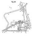
- Figs. 2A and 2Bprovide a right side view of the mechanism of Fig. 1 with pedals, a handrail and arm handles in a first and in a second position respectively;
- Fig. 3is an enlarged perspective side view of a portion of the belt and pulley arrangement of the mechanism of Fig. 2B;
- Fig. 4is a schematic and block diagram of a control system for the mechanism of Figs. 1 and 5.
- Fig. 5is a right perspective side view illustrating certain aspects of a second embodiment of a climber mechanism
- Fig. 6is a right perspective side view of a portion of the climber mechanism of Fig. 5 illustrating certain aspects of the handle bar arrangement and support frame;
- Fig. 7is a sectioned right perspective side view of a portion of the climber mechanism of Fig. 5 illustrating certain aspects of the track and pedal assemblies;
- Fig. 8is an exploded view of the pedal assembly of Fig. 8;
- Fig. 9is a right sectioned view of the climber of Fig. 5 illustrating a load and pedal connection assembly that can be used with the climber of FIG. 5;
- Fig. 10is an enlarged sectioned perspective view of the load and pedal connection assembly of FIG. 9;
- Fig. 11is an enlarged sectioned bottom perspective view taken along lines 11-11 of Fig. 10 illustrating a portion of the pedal connection assembly and a pedal impact absorption arrangement;
- Fig. 12 A and Fig. 12Bprovide enlarged side perspective views of the pedal connection assembly of Fig. 11 in a first and in a second position respectively;
- Fig. 13is a sectioned enlarged top perspective view of a pedal link to rocker connection assembly that can be used with the climber of Fig. 5.
- Figs. 1, 2A-B and 3provide views of an example of a first embodiment of a climber mechanism 10 that provides an illustrative environment for describing certain aspects a climber mechanism 10. For simplicity, only the right pedal, handrails and arm handles of the climber mechanism 10 are shown in Figs. 2A-B.
- a frame 12that includes: a horizontal frame member 14, a forward floor support 16, a rear floor support 18, a curved center support 20 secured to the horizontal support member 14 and forward floor support 16, a central vertical frame member 22 secured between the horizontal frame member 14 and the curved center support 20, and a vertical support member 24 secured to the curved center support 20 by a pair of brackets 26 and to the horizontal support member 14.
- a handrail support 28that is attached to the vertical support member 24 is a pair of side handrails 30 and 32 and a pair of generally upwardly extending fixed hand supports 34 and 36.
- a pair of tracks 38 and 40are connected to the vertical frame member 22 and the horizontal frame member 14 at an angle of preferably about 30 degrees to the floor. It has been found that an angle of 30 degrees provides the preferred angle to simulate the climbing of terrain such as hills, although variations of 10 to 15 degrees from the preferred 30 degrees can in some circumstances be desirable.
- a rear frame member 41is located between the tracks 38 and 40 and likewise connected to the vertical frame member 22 and the horizontal frame member 14 such that the member 41 is parallel to the tracks 38 and 40.
- the climbing mechanismincludes a pair of pedals 42 and 44 that are mounted for movement along the tracks 38 and 40 respectively.
- the pedals 42 and 44can be mounted on the tracks 38 and 40 by a number of different mechanisms, preferably a pair of pedal support mechanisms 46 and 48 of the type as shown in Figs. 6 and 7 of U.S. Patent No. 6,905,441 are used for this purpose and in this case would include a set of guide rollers 50.
- the tracks 38 and 40are substantially linear although there may be some implementations of the climbing mechanism 10 where nonlinear or curved tracks might be desirable.
- a belt 52is attached to a lower rear portion of each of the pedal support mechanisms 46 and 48 at a point 54 and lead around a pulley 56 that in turn is rotatably attached to the rear frame member 41.
- a drive belt 62is also attached at a point 58 of the right pedal mechanism 46 and to a point 60 of the second pedal mechanism 48.
- the belt 52is a ribbed rubber belt but other flexible members can be used such a linked chain.
- the drive belt 62extends from the first pedal mechanism 46 to an idler pulley 64 mounted for rotation on frame member 22 then extends to downwardly over the pulley 64 to a first one way clutch 66.
- the drive belt 62is engaged with a grooved pulley on the first one way clutch 66, twisted 90 degrees and extends up and over a central idler pulley 68.
- the central idler pulley 68is mounted for rotation on the frame member 20 utilizing a pulley support structure 70 as shown in the figures. Twisted back 90 degrees, the control belt 62 is engaged with a second one-way clutch 72 mounted for rotation on frame member 22 then extends to the attachment point 60 on the second pedal mechanism 44.
- the pedal connection mechanism including belt 52although not necessary for the basic operation of the climber 10, will act to cause one of the pedals, for example pedal 42 to move downwardly along track 38 when the other pedal, for example pedal 44 moves upwardly along the track 40.
- the pedal connection mechanism including the drive belt 62will act to cause one of the pedals, for example pedal 42 to move upwardly along track 38 when the other pedal, for example pedal 44 moves downwardly along the track 40.
- Figs. 2A, 2B and 3illustrate one type of mechanism that can be used for providing a load or resistance to movement of the pedals 42 and 44 in a downward direction.
- the resistance mechanismindicated generally at 74, is a drive pulley 76 secured to a shaft 78.
- the shaft 78is mounted for rotation in the vertical frame member 22 and in this embodiment 10 both of the one way clutches 66 and 72 are also secured to the shaft 78 for rotation with the shaft 78.
- a first belt 80is engaged with the drive pulley 76 and a first intermediate pulley 82 that is secured for rotation on a shaft 84 that in turn is mounted for rotation on the curved frame member 20.
- a second intermediate pulley 86is also secured for rotation with the shaft 84.
- an alternator 88that includes a flywheel 90 is secured to the curved frame member 20 and is connected to the second intermediate pulley 86 by a second drive belt 92 engaged with an alternator pulley 94 secured on an alternator shaft 96 as is the flywheel 90.
- the pulleys 76, 86 and 94 along with the intermediate belts 80 and 92form a speed increasing transmission so that the alternator shaft will rotate at a significantly greater speed than the shaft 78.
- this embodiment 10 of the climber mechanismalso has, as is conventional in exercise equipment of this type, a control panel 96 that includes an information display 98 and a set of user controls 100.
- the control panel 96is secured to the vertical support member 24 and includes a microprocessor 102 for controlling the climbing mechanism 10. It should be noted that the microprocessor 102 or a similar control circuitry can be located elsewhere on the climber mechanism 10.
- One of the advantages of the type of apparatus described herein, especially the use of linear tracks 38 and 40 for the foot pedals 42 and 44 where the pedals 42 and 44 are connected for dependent operation, as for example by the single belt 62,is that it is possible for the apparatus 10 to maintain a constant torque on the one way clutches 66 and 72. This characteristic facilitates the implementation of exercise programs where either the pedals 42 and 44 are maintained at a constant speed by varying the resistance generated by the alternator 88 or the alternator 88 can be programmed to provide a constant resistance where the pedals 42 and 44 vary in speed.
- the climber mechanism 10 as described abovecan be modified to also provide a total body exercise program.
- this embodiment of the upper body mechanismcan include a pair of moveable arm handles 104 and 106.
- the moveable arm handles 104 and 106are pivotally attached to the vertical frame member 24 along with a pair of corresponding arm extensions or rocker members 108 and 110.
- the arm rockers 108 and 110are in turn connected to the pedal support mechanisms 46 and 48 by a pair of links 112 and 114 that can be comprised of rods or metal tubes for example.
- the links 112 and 114are preferably composed of a rigid material but, under certain circumstances, a flexible material such as a wire cable could be used where, for example, some independence between the movement of the pedals 42 and 44 and the arm handles 104 and 106 is desired.
- the moveable arm handles 104 and 106will move in synchronism with the corresponding foot pedals 42 and 44 thereby providing the user with exercise that involves his arms and upper body as well as his legs and lower body.
- other arrangementscan be used to connect the arm handles 106 and 108 to the pedals 44.
- flexible memberssuch as cables can be used instead of the rods 112 and 114 especially in the type of apparatus where the belt 52 is used to connect the pedal support mechanisms 46 and 48.
- Figs. 5-13depict various aspects of a second and preferred embodiment 200 of a climber mechanism.
- the climber 200includes a control panel 96 having a display 98 and user controls 100.
- the climber 200can operate in the same manner as the embodiment 10 described above.
- Figs. 5 and 6provide perspective external views of the climber 200 that includes a pair of foot pedal assemblies indicated at 202 and 204, each having a foot pedal 206 and 208.
- the foot pedal assemblies 202 and 204move or reciprocate along a pair of track assemblies 210 and 212 that a shown in detail in Fig. 7.
- Various frame elementssuch as a front forward floor support 214 and a vertical frame member 216 provide support for the climber 200 on the horizontal surface 11.
- the vertical support 216is a monocolumn formed out of a generally cylindrical metal tube.
- a pair of side handrails 218 formed out of a cylindrical and 220can be added to the climber 200.
- the handrails 218 and 220are formed out of a single tubular material and are secured to the vertical member 216 by a bracket 222 or other suitable connection means.
- the handrails 218 and 220although not necessary to the operation an apparatus of the type 200, can provide additional structural support or act as part of the frame structure for the climber 200.
- the preferred embodiment of the climber 200includes a pair of fixed arm handles 224 and 226 that are secured to the frame and in this case the vertical frame member 216.
- the climber 200also provides a total body exercise capability by, in this embodiment, including a pair of movable arm handles 228 and 230 that are connected to the foot pedal assemblies 202 and 204 for movement in unison therewith.
- the moveable arm handles 228 and 230are included in a pair of an arm handle assemblies where the right arm handle assembly is indicated generally by 232.
- the preferred embodiment of the arm handle assembly 232includes a rocker member 234 pivotally connected at a point 235 to a link member 236.
- the rocker 234is secured to a hub member 238 that in turn is free to rotate about a shaft (not shown) which can be secured to the monocolumn 216 or other parts of the frame.
- the arm handle 228attached to the hub 238 is the arm handle 228.
- the arm handle assembly 232is effective to connect the arm handle 202 to the foot pedal assembly 202 such that the arm handle 202 will rotate back and forth as the foot pedal 206 moves up and down along the track assembly 212.
- the left arm handle assembly including the arm handle 230operates in the same manner.
- the climber 200is the addition of a step 240 secured over the ends of the handrails 218 and 220.
- the step 240makes it easier for a user mount the climber 200 by shortening the distance the user needs to reach or step on to the pedals 206 and 208.
- the climber 200additionally includes a housing 242 as a protective element.
- Fig. 6illustrates another feature which is a three point support arrangement for the climber 200 where the climber 200 is essentially supported on the floor 11 by the monocolumn 216 and the handrails 218 and 220.
- the track assemblies 210 and 212can also be used to provide this support. This arrangement makes it possible to do away with a longitudinal frame member such as the horizontal frame member 14 shown in Fig. 2A.
- Fig. 7is a sectioned view depicting details of the track assemblies 210 and 212 of the preferred embodiment of the climber 200.
- Each of the track assemblies 210 and 212includes a track, represented by the right track 244, that are secured at their forward end to the monocolumn 216 and their reward end to a horizontal rear floor support member 246.
- Covering the tracks including the track 244are a pair of track covers 248 and 250.
- the track cover 248is shown in Fig. 7 in broken away form and slid upwardly and in a forward direction as indicated by an arrow 251. This arrangement allows ready access the tracks, including track 244, for assembly and maintenance purposes.
- the preferred structure of the climber 200includes a central structural member 252 that is directly connected between the monocolumn 216 and the rear support member 246.
- a bracket arrangement 254is used to connect the tracks, including track 244, to the central structural member 252 and hence to the monocolumn 216 and a second bracket or clamping arrangement indicated at 256 can be used to connect the tracks including track 244 to the rear support member 246 and the central structural member 252.
- a central cover 258, shown in exploded form in Fig. 7,is used to cover the central structural member 252.
- a pair of lower track housings, represented at 260can be used to further enclose the track assemblies 210 and 212.
- the step 240also serves to enclose the rear floor support member 246 as well as the bracket arrangement 256. It should be appreciated that by using housings and covers of the type 248, 250, 256, 258 and 260, not only can user safety be enhanced but maintenance activities can be reduced since elements of the pedal assemblies 202 and 204 as well as the track assemblies can be substantially enclosed and largely protected from sweat and other user generated debris.
- Fig. 8illustrates in exploded form the preferred embodiment of the pedal assembly 204 which is configured to operate on the track 244 that has a rectangular cross-section having an upper 258 and a lower 260 planar surfaces along with a pair of planar side surfaces 262 and 264.
- a roller carriage 266having a front top roller 268 and a rear top roller 270 along with a bottom roller 272 is engaged with the track 244.
- the carriage 266can also include one or more side rollers such as a set of rollers 272 and 274 that abut the lateral surface 262 of the track 244 along with one or more side rollers that abut the other lateral side surface 264 of the track 244 in order to aid in aligning the carriage 266 on the track 244.
- roller arrangementscan be used with a track of the type 244 such as the configuration shown in U.S. Patent No. 6,905,441
- the arrangement shown in Fig. 8is preferred since the two top rollers 268 and 270 in combination with a single bottom roller 272 located beneath provides sufficient support for the pedal 206 on the track 244 for a climber type apparatus of the type 200, especially when the tracks are orientated at about a thirty degree angle with the floor 11.
- the carriage 266 in the preferred embodiment of the pedal assembly 202is then secured within a pedal bracket 278 with a lower attachment plate 280 with a set of fasteners indicated at 282.
- the pedal 206is attached to a pair of flanges 284 and 286 configured on the upper portion of the pedal bracket 278 by a set of fasteners indicated at 290 and 292 that are secured through a pair of mounting members such as 294 configured in the pedal 206.
- the pedal bracket 278also encompasses the track cover 248 permitting the carriage 266 and hence the pedal 206 to move along the track 264.
- the mounting member 294also includes an aperture 296 for receiving a shaft 298 that is used to pivotally connect the link 236 to the pedal assembly 202 as shown in Fig. 5.
- Figs. 9, 10 and 11depict the preferred arrangement, which can be used in the climber 200 to control the operation of the pedals 206 and 208 including providing a load or resistance to the downward movement of the pedals 206 and 208.
- a belt 300is attached to a bracket 302 and 304 that extends from the lower portion of the pedal assemblies 202 and 204 respectively.
- the belt 300is attached to the brackets 302 and 304 by a pair of clamping assemblies 306 and 308 and lead around a pulley 310 that in turn is rotatably attached to the central structural member 252.
- the belt 312is preferably a ribbed rubber belt but other flexible members can be used such a linked chain.
- the drive belt 312extends from the first pedal assembly 202 to a grooved pulley 314 secured for rotation with a first one-way clutch 316 that in turn is mounted for rotation on shaft 318 secured to a frame member indicated at 320.
- the drive belt 312is twisted 90 degrees and extends down and under an idler pulley 322 that is mounted for rotation on a frame member 324. Twisted back 90 degrees, the drive belt 312 is engaged with a second grooved pulley 326 which is secured to a second one-way clutch 328 that is mounted for rotation on the shaft 318.
- the drive belt 312then extends to the attachment point 308 on the pedal assembly 204.
- resistanceis preferably provided by a mechanism that includes a drive pulley 330 secured for rotation with the shaft 318.
- a first belt 332is engaged with a shaft 334 or small pulley mounted for rotation on the frame.
- An intermediate pulley 336is secured for rotation on the shaft 334.
- the alternator 88 that includes the flywheel 90is mounted to the frame 20 and is connected to the intermediate pulley 336 by a second belt 338 engaged with an alternator pulley (not shown) secured on the alternator shaft 96 as is the flywheel 90.
- the pulleys 330 and 336 along with the belts 332 and 338form a speed increasing transmission so that the alternator shaft 96 will rotate at a significantly greater speed than the shaft 318.
- the transmissionhas been described in terms of the preferred embodiment, but there are many different arrangements that can be used for providing a resistance force to the pedals 206 and 208 including different types of transmission mechanisms such as geared arrangements and hydraulic mechanisms along with different sources of a resistance force including eddy current brakes and friction mechanisms.
- Figs. 11, 12A and 12Billustrate the preferred embodiment of an impact absorption assembly 340 that can be used with an exercise apparatus such as the climber 200.
- One of the objects of the impact absorption assembly 340is to reduce impact forces on the user's feet as the pedals 206 and 208 reach or hit the bottom of the apparatus 200.
- a resilient member 342is secured to a support flange 344 extending downwardly from the plate 280 on the pedal assembly 202 and a corresponding resilient member 346 is secured to a support flange 348 on the other pedal assembly 204.
- a second set of resilient members 350 and 352can be attached to the lower end of the climber 200 such as the member 246 and aligned with the resilient members 342 and 346 respectively so that the members 342, 346, 350 and 352 will compress when the downward motion of each of the pedals 206 and 208 terminates at the bottom of the apparatus 200 as depicted in Figs. 12A and 12B.
- resilient membersincluding metal springs
- the preferred constructionis an elliptically shaped member composed of an elastomeric material.
- One advantage of an elliptical configurationis that it provides a variable deflection rate which tends to further reduce impact stresses on the user's feet and legs. Also, as shown in Fig.
- one of the resilient members, here 350has a greater deflection rate than the other resilient member 342 which can further reduce impact stresses.
- TECSPAK® elastomeric bumpersprovide a suitable configuration and material for the resilient members 342, 346, 350 and 352.
- Fig. 13shows a preferred method for pivotally attaching the rocker 234 to the link 236 at point 235.
- a shaft 354is inserted through the rocker 234 with a ball and socket assembly 356 attaching an end 358 of the link member 236 to the shaft 354.
- a spring clip 360is secured at a first end between the rocker 234 and the ball joint 356 on the shaft 354 and at its other end to the end 358 of the link member.
Landscapes
- Health & Medical Sciences (AREA)
- General Health & Medical Sciences (AREA)
- Physical Education & Sports Medicine (AREA)
- Cardiology (AREA)
- Vascular Medicine (AREA)
- Life Sciences & Earth Sciences (AREA)
- Biophysics (AREA)
- Orthopedic Medicine & Surgery (AREA)
- Rehabilitation Tools (AREA)
- Measurement Of The Respiration, Hearing Ability, Form, And Blood Characteristics Of Living Organisms (AREA)
- Mechanical Control Devices (AREA)
Abstract
Description
- This application claims priority on provisional application Serial No.
60/781,838, filed March 13, 2006 - The described apparatus relates generally to exercise equipment and, more particularly, to exercise equipment that can be used to provide a user with a climbing type exercise.
- Climbing is recognized as a particularly effective type of aerobic exercise, and as a result, exercise machines facilitating this type of exercise are popular for both home and health club use. There have been a variety of approaches taken in designing stair climbing apparatus as illustrated in
U.S. Patent Nos. 3,497,215 ,4,687,195 ,5,135,447 ,5,180,351 ,5,195,935 ,5,222,928 ,5,238,462 ,5,318,487 ,5,403,252 ,6,855,093 ,7,153,238 andRe. 34,959 as well asPCT application WO/94/02214 - Therefore, given the increasing popularity of climbing as an exercise, one object of the described apparatus is to provide an improved climbing exercise apparatus as well as an apparatus that can provide for an improved climbing experience.
- Fig. 1 is a right perspective side view of a climber mechanism illustrating a first embodiment of certain aspects of a climber mechanism;
- Figs. 2A and 2B provide a right side view of the mechanism of Fig. 1 with pedals, a handrail and arm handles in a first and in a second position respectively;
- Fig. 3 is an enlarged perspective side view of a portion of the belt and pulley arrangement of the mechanism of Fig. 2B; and
- Fig. 4 is a schematic and block diagram of a control system for the mechanism of Figs. 1 and 5.
- Fig. 5 is a right perspective side view illustrating certain aspects of a second embodiment of a climber mechanism;
- Fig. 6 is a right perspective side view of a portion of the climber mechanism of Fig. 5 illustrating certain aspects of the handle bar arrangement and support frame;
- Fig. 7 is a sectioned right perspective side view of a portion of the climber mechanism of Fig. 5 illustrating certain aspects of the track and pedal assemblies;
- Fig. 8 is an exploded view of the pedal assembly of Fig. 8;
- Fig. 9 is a right sectioned view of the climber of Fig. 5 illustrating a load and pedal connection assembly that can be used with the climber of FIG. 5;
- Fig. 10 is an enlarged sectioned perspective view of the load and pedal connection assembly of FIG. 9;
- Fig. 11 is an enlarged sectioned bottom perspective view taken along lines 11-11 of Fig. 10 illustrating a portion of the pedal connection assembly and a pedal impact absorption arrangement;
- Fig. 12 A and Fig. 12B provide enlarged side perspective views of the pedal connection assembly of Fig. 11 in a first and in a second position respectively;
- Fig. 13 is a sectioned enlarged top perspective view of a pedal link to rocker connection assembly that can be used with the climber of Fig. 5.
- Figs. 1, 2A-B and 3 provide views of an example of a first embodiment of a
climber mechanism 10 that provides an illustrative environment for describing certain aspects aclimber mechanism 10. For simplicity, only the right pedal, handrails and arm handles of theclimber mechanism 10 are shown in Figs. 2A-B. Support for themechanism 10 on ahorizontal support surface 11 such as a floor is provided by aframe 12 that includes: ahorizontal frame member 14, aforward floor support 16, arear floor support 18, acurved center support 20 secured to thehorizontal support member 14 andforward floor support 16, a centralvertical frame member 22 secured between thehorizontal frame member 14 and thecurved center support 20, and avertical support member 24 secured to thecurved center support 20 by a pair ofbrackets 26 and to thehorizontal support member 14. In addition, extending from ahandrail support 28 that is attached to thevertical support member 24 is a pair ofside handrails tracks vertical frame member 22 and thehorizontal frame member 14 at an angle of preferably about 30 degrees to the floor. It has been found that an angle of 30 degrees provides the preferred angle to simulate the climbing of terrain such as hills, although variations of 10 to 15 degrees from the preferred 30 degrees can in some circumstances be desirable. Arear frame member 41 is located between thetracks vertical frame member 22 and thehorizontal frame member 14 such that themember 41 is parallel to thetracks - The climbing mechanism includes a pair of
pedals tracks pedals tracks pedal support mechanisms U.S. Patent No. 6,905,441 are used for this purpose and in this case would include a set ofguide rollers 50. By the same token, thetracks climbing mechanism 10 where nonlinear or curved tracks might be desirable. In this particular implementation of theclimber 10, abelt 52 is attached to a lower rear portion of each of thepedal support mechanisms point 54 and lead around apulley 56 that in turn is rotatably attached to therear frame member 41. Also attached at apoint 58 of theright pedal mechanism 46 and to a point 60 of thesecond pedal mechanism 48 is adrive belt 62. Preferably, thebelt 52 is a ribbed rubber belt but other flexible members can be used such a linked chain. In the embodiment of the climber mechanism shown in Figs. 1-4, thedrive belt 62 extends from thefirst pedal mechanism 46 to anidler pulley 64 mounted for rotation onframe member 22 then extends to downwardly over thepulley 64 to a first oneway clutch 66. Thedrive belt 62 is engaged with a grooved pulley on the first oneway clutch 66, twisted 90 degrees and extends up and over acentral idler pulley 68. Thecentral idler pulley 68 is mounted for rotation on theframe member 20 utilizing apulley support structure 70 as shown in the figures. Twisted back 90 degrees, thecontrol belt 62 is engaged with a second one-way clutch 72 mounted for rotation onframe member 22 then extends to the attachment point 60 on thesecond pedal mechanism 44. - In operation, the pedal connection
mechanism including belt 52, although not necessary for the basic operation of theclimber 10, will act to cause one of the pedals, forexample pedal 42 to move downwardly alongtrack 38 when the other pedal, forexample pedal 44 moves upwardly along thetrack 40. By the same token, the pedal connection mechanism including thedrive belt 62 will act to cause one of the pedals, forexample pedal 42 to move upwardly alongtrack 38 when the other pedal, forexample pedal 44 moves downwardly along thetrack 40. These connection mechanisms result in what can be termed a dependent pedal operation where the motion of thepedals climber 10, but it should be understood that under certain circumstances independent operation of pedals might be considered desirable for a climber mechanism. - Figs. 2A, 2B and 3 illustrate one type of mechanism that can be used for providing a load or resistance to movement of the
pedals drive pulley 76 secured to ashaft 78. Theshaft 78 is mounted for rotation in thevertical frame member 22 and in thisembodiment 10 both of the oneway clutches 66 and 72 are also secured to theshaft 78 for rotation with theshaft 78. Afirst belt 80 is engaged with thedrive pulley 76 and a firstintermediate pulley 82 that is secured for rotation on ashaft 84 that in turn is mounted for rotation on thecurved frame member 20. Also secured for rotation with theshaft 84 is a secondintermediate pulley 86. To provide a resistance force, analternator 88 that includes aflywheel 90 is secured to thecurved frame member 20 and is connected to the secondintermediate pulley 86 by asecond drive belt 92 engaged with an alternator pulley 94 secured on analternator shaft 96 as is theflywheel 90. In this embodiment of theresistance mechanism 74, thepulleys intermediate belts shaft 78. It will be appreciated that the transmission has been described in terms of the preferred embodiment, but there are many different arrangements that can be used for providing a resistance force to thepedals - As illustrated in Fig. 4, this
embodiment 10 of the climber mechanism, also has, as is conventional in exercise equipment of this type, acontrol panel 96 that includes aninformation display 98 and a set of user controls 100. In thisembodiment 10, thecontrol panel 96 is secured to thevertical support member 24 and includes amicroprocessor 102 for controlling theclimbing mechanism 10. It should be noted that themicroprocessor 102 or a similar control circuitry can be located elsewhere on theclimber mechanism 10. One of the advantages of the type of apparatus described herein, especially the use oflinear tracks foot pedals pedals single belt 62, is that it is possible for theapparatus 10 to maintain a constant torque on the oneway clutches 66 and 72. This characteristic facilitates the implementation of exercise programs where either thepedals alternator 88 or thealternator 88 can be programmed to provide a constant resistance where thepedals - The
climber mechanism 10 as described above can be modified to also provide a total body exercise program. As shown in Figs. 1-3, this embodiment of the upper body mechanism can include a pair of moveable arm handles 104 and 106. Here, the moveable arm handles 104 and 106 are pivotally attached to thevertical frame member 24 along with a pair of corresponding arm extensions orrocker members arm rockers pedal support mechanisms links links pedals rockers links corresponding foot pedals pedals 44. For example, flexible members such as cables can be used instead of therods belt 52 is used to connect thepedal support mechanisms - Figs. 5-13 depict various aspects of a second and
preferred embodiment 200 of a climber mechanism. As with theembodiment 10 shown in Figs. 1-3, theclimber 200 includes acontrol panel 96 having adisplay 98 and user controls 100. In general, theclimber 200 can operate in the same manner as theembodiment 10 described above. - Figs. 5 and 6 provide perspective external views of the
climber 200 that includes a pair of foot pedal assemblies indicated at 202 and 204, each having afoot pedal foot pedal assemblies track assemblies forward floor support 214 and avertical frame member 216 provide support for theclimber 200 on thehorizontal surface 11. In the preferred embodiment, thevertical support 216 is a monocolumn formed out of a generally cylindrical metal tube. A pair ofside handrails 218 formed out of a cylindrical and 220 can be added to theclimber 200. In the preferred embodiment, thehandrails vertical member 216 by abracket 222 or other suitable connection means. In addition to providing support for a user on theclimber 200 thehandrails type 200, can provide additional structural support or act as part of the frame structure for theclimber 200. ln addition to thehandrails climber 200 includes a pair of fixed arm handles 224 and 226 that are secured to the frame and in this case thevertical frame member 216. - In the preferred embodiment, the
climber 200 also provides a total body exercise capability by, in this embodiment, including a pair of movable arm handles 228 and 230 that are connected to thefoot pedal assemblies arm handle assembly 232 includes arocker member 234 pivotally connected at apoint 235 to alink member 236. Here, therocker 234 is secured to ahub member 238 that in turn is free to rotate about a shaft (not shown) which can be secured to themonocolumn 216 or other parts of the frame. Also, attached to thehub 238 is thearm handle 228. As a result, thearm handle assembly 232 is effective to connect the arm handle 202 to thefoot pedal assembly 202 such that thearm handle 202 will rotate back and forth as thefoot pedal 206 moves up and down along thetrack assembly 212. The left arm handle assembly including thearm handle 230 operates in the same manner. - Another aspect of the
climber 200 is the addition of astep 240 secured over the ends of thehandrails step 240 makes it easier for a user mount theclimber 200 by shortening the distance the user needs to reach or step on to thepedals climber 200 additionally includes ahousing 242 as a protective element. - Fig. 6 illustrates another feature which is a three point support arrangement for the
climber 200 where theclimber 200 is essentially supported on thefloor 11 by themonocolumn 216 and thehandrails track assemblies horizontal frame member 14 shown in Fig. 2A. - Fig. 7 is a sectioned view depicting details of the
track assemblies climber 200. Each of thetrack assemblies right track 244, that are secured at their forward end to themonocolumn 216 and their reward end to a horizontal rearfloor support member 246. Covering the tracks including thetrack 244 are a pair of track covers 248 and 250. Thetrack cover 248 is shown in Fig. 7 in broken away form and slid upwardly and in a forward direction as indicated by anarrow 251. This arrangement allows ready access the tracks, includingtrack 244, for assembly and maintenance purposes. Also, the preferred structure of theclimber 200 includes a centralstructural member 252 that is directly connected between themonocolumn 216 and therear support member 246. In this particular implementation of thetrack assemblies bracket arrangement 254 is used to connect the tracks, includingtrack 244, to the centralstructural member 252 and hence to themonocolumn 216 and a second bracket or clamping arrangement indicated at 256 can be used to connect thetracks including track 244 to therear support member 246 and the centralstructural member 252. In this embodiment, acentral cover 258, shown in exploded form in Fig. 7, is used to cover the centralstructural member 252. Also, a pair of lower track housings, represented at 260, can be used to further enclose thetrack assemblies step 240, as shown in Figs. 5 and 6, also serves to enclose the rearfloor support member 246 as well as thebracket arrangement 256. It should be appreciated that by using housings and covers of thetype pedal assemblies - Fig. 8 illustrates in exploded form the preferred embodiment of the
pedal assembly 204 which is configured to operate on thetrack 244 that has a rectangular cross-section having an upper 258 and a lower 260 planar surfaces along with a pair of planar side surfaces 262 and 264. Aroller carriage 266 having a fronttop roller 268 and a reartop roller 270 along with abottom roller 272 is engaged with thetrack 244. Additionally, thecarriage 266 can also include one or more side rollers such as a set ofrollers lateral surface 262 of thetrack 244 along with one or more side rollers that abut the otherlateral side surface 264 of thetrack 244 in order to aid in aligning thecarriage 266 on thetrack 244. It will be appreciated, that although a number of roller arrangements can be used with a track of thetype 244 such as the configuration shown inU.S. Patent No. 6,905,441 , the arrangement shown in Fig. 8 is preferred since the twotop rollers single bottom roller 272 located beneath provides sufficient support for the pedal 206 on thetrack 244 for a climber type apparatus of thetype 200, especially when the tracks are orientated at about a thirty degree angle with thefloor 11. - The
carriage 266 in the preferred embodiment of thepedal assembly 202 is then secured within apedal bracket 278 with alower attachment plate 280 with a set of fasteners indicated at 282. Thepedal 206 is attached to a pair offlanges pedal bracket 278 by a set of fasteners indicated at 290 and 292 that are secured through a pair of mounting members such as 294 configured in thepedal 206. As shown in Figs. 5 and 6, thepedal bracket 278 also encompasses thetrack cover 248 permitting thecarriage 266 and hence the pedal 206 to move along thetrack 264. In this embodiment, the mountingmember 294 also includes anaperture 296 for receiving ashaft 298 that is used to pivotally connect thelink 236 to thepedal assembly 202 as shown in Fig. 5. - Figs. 9, 10 and 11 depict the preferred arrangement, which can be used in the
climber 200 to control the operation of thepedals pedals climber 200, abelt 300 is attached to abracket pedal assemblies belt 300 is attached to thebrackets assemblies pulley 310 that in turn is rotatably attached to the centralstructural member 252. Also attached by the clampingassembly 306 of theright pedal assembly 202 and to the clampingassembly 306 of theleft pedal assembly 308 is adrive belt 312. As with thebelt 62, thebelt 312 is preferably a ribbed rubber belt but other flexible members can be used such a linked chain. In the embodiment of theclimber mechanism 200 thedrive belt 312 extends from thefirst pedal assembly 202 to a groovedpulley 314 secured for rotation with a first one-way clutch 316 that in turn is mounted for rotation onshaft 318 secured to a frame member indicated at 320. Thedrive belt 312 is twisted 90 degrees and extends down and under anidler pulley 322 that is mounted for rotation on aframe member 324. Twisted back 90 degrees, thedrive belt 312 is engaged with a second groovedpulley 326 which is secured to a second one-way clutch 328 that is mounted for rotation on theshaft 318. Thedrive belt 312 then extends to theattachment point 308 on thepedal assembly 204. - As represented in Figs. 9 and 10 in essentially schematic form, resistance is preferably provided by a mechanism that includes a
drive pulley 330 secured for rotation with theshaft 318. Afirst belt 332 is engaged with ashaft 334 or small pulley mounted for rotation on the frame. Anintermediate pulley 336 is secured for rotation on theshaft 334. To provide the resistance force, thealternator 88 that includes theflywheel 90 is mounted to theframe 20 and is connected to theintermediate pulley 336 by asecond belt 338 engaged with an alternator pulley (not shown) secured on thealternator shaft 96 as is theflywheel 90. In this embodiment, thepulleys belts alternator shaft 96 will rotate at a significantly greater speed than theshaft 318. As with thetransmission 74 described above in connection with the embodiment of Figs. 1-3 it will be appreciated that the transmission has been described in terms of the preferred embodiment, but there are many different arrangements that can be used for providing a resistance force to thepedals - Figs. 11, 12A and 12B illustrate the preferred embodiment of an
impact absorption assembly 340 that can be used with an exercise apparatus such as theclimber 200. One of the objects of theimpact absorption assembly 340 is to reduce impact forces on the user's feet as thepedals apparatus 200. ln this particular embodiment, aresilient member 342 is secured to asupport flange 344 extending downwardly from theplate 280 on thepedal assembly 202 and a correspondingresilient member 346 is secured to asupport flange 348 on the otherpedal assembly 204. In addition to or alternatively a second set ofresilient members climber 200 such as themember 246 and aligned with theresilient members members pedals apparatus 200 as depicted in Figs. 12A and 12B. Although a variety of materials and configurations can be used as resilient members including metal springs, the preferred construction is an elliptically shaped member composed of an elastomeric material. One advantage of an elliptical configuration is that it provides a variable deflection rate which tends to further reduce impact stresses on the user's feet and legs. Also, as shown in Fig. 12B, one of the resilient members, here 350, has a greater deflection rate than the otherresilient member 342 which can further reduce impact stresses. TECSPAK® elastomeric bumpers provide a suitable configuration and material for theresilient members - Fig. 13 shows a preferred method for pivotally attaching the
rocker 234 to thelink 236 atpoint 235. As depicted in the sectioned away view of Fig. 13, ashaft 354 is inserted through therocker 234 with a ball andsocket assembly 356 attaching an end 358 of thelink member 236 to theshaft 354. To prevent rotation of thelink 236 about its axis, aspring clip 360 is secured at a first end between therocker 234 and the ball joint 356 on theshaft 354 and at its other end to the end 358 of the link member. - The above descriptions represent preferred embodiments of a climber mechanism intended for heavy duty health club type usage along with the preferred embodiments of various features and arrangements that can be used in this type exercise machines or related machines such as stairclimbers. The inclusion and implementation of various features such as moving arm handles, pedal mechanisms, resistive load mechanisms and shock absorption arrangements will depend on a number of factors including the purpose and cost of the apparatus. For example, for machines that are intended for health club usage a sophisticated control system is made possible by the use of an alternator whereas in a low cost home machine, a simple friction device might suffice and an impact absorption mechanism might not be considered necessary.
Claims (35)
- An exercise apparatus comprising:a frame adapted for placement on a horizontal surface;a first substantially linear track secured to said frame; a second substantially linear track secured to said frame in parallel with said first track wherein said first and second tracks are secured to said frame at an incline from said horizontal surface;a first and a second foot pedal assembly, each including a foot pedal, wherein said foot pedal assemblies are engaged with said first and second tracks respectively for movement along said tracks such that said foot pedals move substantially linearly along and in parallel with said tracks;a first arm handle assembly including a first arm handle operatively connected to said frame and said first foot pedal assembly such that said first arm handle will move in unison with said first foot pedal assembly; anda second arm handle assembly including a second arm handle operatively connected to said frame and said second foot pedal assembly such that said second arm handle will move in unison with said second foot pedal assembly.
- The apparatus of Claim 1 wherein said first and second arm handle assemblies include a first and a second rocker pivotally connected to said frame and to said first and second arm handles respectively and a first link member pivotally connected to said first rocker and said first foot pedal assembly effective to implement said movement of said first arm handle with said first pedal assembly and a second link member pivotally connected to said second rocker and said second foot pedal assembly effective to implement said movement of said second arm handle with said second pedal assembly.
- The apparatus of Claim 1 including a first connection mechanism including a first flexible member connecting said first pedal assembly to said second pedal assembly and engaged with said frame effective to cause said first pedal assembly to move upwardly along said first track when said second pedal assembly is moved downwardly along said second track.
- The apparatus of Claim 3 including a second connection mechanism including a second flexible member connecting said first pedal assembly to said second pedal assembly with said flexible member engaged with said frame effective to cause said first pedal assembly to move downwardly along said first track when said second pedal assembly is moved upwardly along said second track.
- The apparatus of Claim 4 wherein said second connection mechanism includes said second flexible member engaged with an idler pulley secured for rotation on said frame adjacent to a lower portion of said tracks.
- The apparatus of Claim 3 including a resistance mechanism including a transmission and a resistance device operatively connected to said first flexible member for providing resistance to the downward movement of said first and second pedals.
- The apparatus of Claim 6 wherein said transmission includes a first and a second oneway clutch each rotatably secured to said frame and engaged with said first flexible member and a speed increasing transmission operatively connected to said first and second oneway clutches and said resistance device.
- The apparatus of Claim 7 wherein said first connection mechanism includes an idler pulley secured for rotation on said frame and said first flexible member is engaged with said idler pulley intermediate its engagement with said first oneway clutch and said second oneway clutch.
- The apparatus of Claim 2 including:a first connection mechanism including a first flexible member connecting said first pedal assembly to said second pedal assembly via a first idler pulley secured for rotation on said frame effective to cause said first pedal assembly to move upwardly along said first track when said second pedal assembly is moved downwardly along said second track;a resistance mechanism including a transmission, having a first and a second oneway clutch each rotatably secured to said frame and engaged with said first flexible member wherein said first flexible member is engaged with said first idler pulley intermediate said first and said second oneway clutches and a speed increasing transmission operatively connected to said first and second oneway clutches and to a resistance device; anda second connection mechanism including a second flexible member engaged with an idler pulley secured for rotation on said frame adjacent to a lower portion of said tracks connecting said first pedal assembly to said second pedal assembly with said flexible member engaged with said frame effective to cause said first pedal assembly to move downwardly along said first track when said second pedal assembly is moving upwardly along said second track.
- The apparatus of Claim 1 additionally including a side handrail secured to said frame extending upwardly from a back portion of said frame to a front portion of said frame along a first side of the apparatus effective to provide support for a user standing on said foot pedals.
- The apparatus of Claim 10 wherein said front portion of said frame includes a vertical frame member and said side handrail is secured to said vertical frame member.
- The apparatus of Claim 11 wherein said side handrail additionally extends from said vertical frame member downwardly to said back portion of said frame along a second side of the apparatus.
- The apparatus of Claim 10 additionally including at least one fixed arm handle secured to said frame.
- The apparatus of Claim 13 wherein said fixed arm handle is secured to said vertical frame member.
- The apparatus of Claim 11 wherein said first and said second arm handle assemblies are pivotally secured to said vertical member.
- The apparatus of Claim 1 wherein said incline of said tracks is approximately thirty degrees from said horizontal surface.
- The apparatus of Claim 1 additionally including a first and a second track cover secured to said frame covering the upper surfaces of said first and second tracks respectively.
- An exercise apparatus comprising:a frame adapted for placement on a horizontal surface;a first track secured to said frame and a second track secured to said frame in parallel with said first track wherein said first and second tracks are secured to said frame at an incline from said horizontal surface and;a first and a second track cover secured to said support frame and over said first and second said tracks respectively; anda pair of pedal assemblies each one including a foot pedal wherein each pedal assembly is engaged with one of said tracks such that said foot pedals can move along said tracks and wherein each of said pedal assemblies encompasses both its associated track and its associated track cover.
- The apparatus of Claim 18 additionally including a central cover secured to said frame between said tracks.
- The apparatus of Claim 18 wherein said first and second pedal assemblies each include a roller carriage and a plurality of rollers rotatably secured to said carriage such that said rollers engage said track and a pedal bracket secured to said roller carriage and said pedal wherein said pedal bracket encompasses both its associated track and its associated track cover.
- The apparatus of Claim 18 wherein said first and said second tracks are substantially linear and said incline with respect to the horizontal surface is approximately 30 degrees.
- An exercise apparatus comprising:a frame adapted for placement on a horizontal surface;a first substantially linear track secured to said frame; a second substantially linear track secured to said frame in parallel with said first track wherein said first and second tracks are secured to said frame at an incline from said horizontal surface;a first and a second foot pedal assembly, each including a foot pedal, wherein said foot pedal assemblies are engaged with said first and second tracks respectively for movement along said tracks such that said foot pedals move substantially linearly along and in parallel with said tracks;a first connection mechanism including a first flexible member connecting said first pedal assembly to said second pedal assembly effective to cause said first pedal assembly to move upwardly along said first track when said second pedal assembly is moved downwardly along said second track;a resistance mechanism engaged with said first flexible member; anda second connection mechanism including a second flexible member effective to cause said first pedal assembly to move downwardly along said first track when said second pedal assembly is moving upwardly along said second track.
- The apparatus of Claim 22 wherein said first and said second tracks are substantially linear and said incline with respect to the horizontal surface is approximately 30 degrees.
- The apparatus of Claim 22 wherein said second flexible member is engaged with an idler pulley secured for rotation on said frame adjacent to a lower portion of said tracks.
- The apparatus of Claim 22 including a resistance mechanism having a first and a second oneway clutch each rotatably secured to said frame and engaged with said first flexible member and a speed increasing transmission operatively connected to said first and second oneway clutches and said resistance device wherein said first connection mechanism includes an idler pulley secured for rotation on said frame and said first flexible member is engaged with said idler pulley intermediate its engagement with said first oneway clutch and said second oneway clutch.
- An exercise apparatus comprising:a frame adapted for placement on a horizontal surface;a first track secured to said frame and a second track secured to said frame in parallel with said first track wherein said first and second tracks are secured to said frame at an incline from said horizontal surface;a pair of pedal assemblies each one including a pedal mechanism having a foot pedal wherein each pedal mechanism is engaged with one of said tracks such that said foot pedals can move upwardly and downwardly along said tracks; andwherein said frame includes a lower frame member disposed to the horizontal surface at the rearward portion of the apparatus and a set of first resilient members interposed between each of said first and second pedal assemblies and said lower frame member effective to absorb at least a portion of the impact of said pedal assemblies as they reach the downward end of said tracks.
- The apparatus of Claim 26 wherein each of said first resilient members is secured to said lower frame member.
- The apparatus of Claim 26 wherein each of said first resilient members is secured to one of said pedal assemblies.
- The apparatus of Claim 28 additionally including a second set of resilient members wherein each of said second resilient members is secured to said lower frame member and aligned with a corresponding one of said first resilient members so as to contribute to said absorption of impact.
- The apparatus of Claim 26 wherein said first resilient members have an elliptical configuration.
- The apparatus of Claim 29 wherein said first and said second resilient members have an elliptical configuration.
- An exercise apparatus comprising:a frame adapted for placement on a horizontal surface including a forward support structure at the forward end of the apparatus and a rear support structure adapted to support the rear of the apparatus on said horizontal surface;a pair of pedal assemblies each one including a pedal wherein said pedal assemblies are operatively associated with said frame such that said pedals can reciprocate in at least a partially vertical motion; anda step member disposed to said rear support structure configured to provide a user step from the horizontal surface to said pedals.
- The apparatus of Claim 32 wherein said rear support includes a horizontal support member.
- The apparatus of Claim 32 additionally including at least one side handrail secured between said forward support structure and said rear support structure effective to provide support for a user standing on said pedals.
- The apparatus of Claim 34 wherein said rear support includes a horizontal support member and one end of said side handrail is secured to said horizontal support member.
Applications Claiming Priority (2)
| Application Number | Priority Date | Filing Date | Title |
|---|---|---|---|
| US78183806P | 2006-03-13 | 2006-03-13 | |
| US11/710,577US7771324B2 (en) | 2006-03-13 | 2007-02-26 | Climber mechanism |
Publications (3)
| Publication Number | Publication Date |
|---|---|
| EP1834674A2true EP1834674A2 (en) | 2007-09-19 |
| EP1834674A3 EP1834674A3 (en) | 2007-12-12 |
| EP1834674B1 EP1834674B1 (en) | 2012-01-04 |
Family
ID=38888136
Family Applications (1)
| Application Number | Title | Priority Date | Filing Date |
|---|---|---|---|
| EP07251021ACeasedEP1834674B1 (en) | 2006-03-13 | 2007-03-13 | Climber mechanism |
Country Status (4)
| Country | Link |
|---|---|
| US (6) | US20070219065A1 (en) |
| EP (1) | EP1834674B1 (en) |
| CN (1) | CN101036833A (en) |
| CA (3) | CA2744974C (en) |
Cited By (6)
| Publication number | Priority date | Publication date | Assignee | Title |
|---|---|---|---|---|
| EP2067504A1 (en)* | 2007-12-07 | 2009-06-10 | Sports Art Industrial Co., Ltd. | Exercise Machine Provided with a Footplate Device |
| EP2186549A1 (en) | 2008-11-10 | 2010-05-19 | Sports Art Industrial Co., Ltd. | Athletic apparatus with non-parallel linear sliding track |
| EP2186550A1 (en)* | 2008-11-10 | 2010-05-19 | Sports Art Industrial Co., Ltd. | Athletic apparatus with non-linear sliding track |
| WO2014142641A1 (en)* | 2013-03-11 | 2014-09-18 | Mercenari Uribe Fernando Humberto | Integral vertical stepper |
| EP3218072A4 (en)* | 2015-12-07 | 2018-01-10 | Synergy Fitness (Asia) Limited | Fluid displacement stationary exercise equipment with continuously variable transmission |
| WO2021164384A1 (en)* | 2020-02-20 | 2021-08-26 | 孙登元 | Climbing machine |
Families Citing this family (70)
| Publication number | Priority date | Publication date | Assignee | Title |
|---|---|---|---|---|
| US7731634B2 (en)* | 2005-02-09 | 2010-06-08 | Precor Incorporated | Elliptical exercise equipment with stowable arms |
| US20070219065A1 (en)* | 2006-03-13 | 2007-09-20 | Anderson Timothy T | Climber apparatus |
| US8109861B2 (en)* | 2006-08-10 | 2012-02-07 | Exerciting, Llc | Exercise device with varied gait movements |
| US7833133B2 (en)* | 2006-12-28 | 2010-11-16 | Precor Incorporated | End of travel stop for an exercise device |
| US8033961B2 (en)* | 2008-10-15 | 2011-10-11 | Sports Art Industrial Co., Ltd. | Athletic apparatus with non-linear sliding track |
| US7927257B2 (en)* | 2008-10-21 | 2011-04-19 | Rakesh Patel | Assisted stair training machine and methods of using |
| US7621849B1 (en)* | 2008-11-14 | 2009-11-24 | Cheng-Ta Tsai | Stepper |
| JP5770714B2 (en)* | 2009-04-15 | 2015-08-26 | プリコー インコーポレイテッドPrecor, Inc. | Exercise device with flexible element |
| US8047968B2 (en)* | 2009-10-14 | 2011-11-01 | Brian Charles Stewart | Simulated climbing and full body exercise and method |
| US20110193312A1 (en)* | 2010-02-09 | 2011-08-11 | John Fabian | Drive Apparatus |
| US9375606B1 (en)* | 2011-06-17 | 2016-06-28 | Joseph D Maresh | Exercise methods and apparatus |
| US8469863B2 (en)* | 2011-06-28 | 2013-06-25 | Preventive Medical Health Care Co., Ltd. | Rehabilitation exercising equipment that can extend a user's arms |
| CN103041542A (en)* | 2012-12-20 | 2013-04-17 | 成都绿迪科技有限公司 | Body-building appliance |
| TW201427749A (en)* | 2013-01-07 | 2014-07-16 | Dyaco Int Inc | Exercise device with leg elliptical orbit |
| US9114275B2 (en)* | 2013-03-04 | 2015-08-25 | Brunswick Corporation | Exercise assemblies having crank members with limited rotation |
| US9138614B2 (en) | 2013-03-04 | 2015-09-22 | Brunswick Corporation | Exercise assemblies having linear motion synchronizing mechanism |
| US9050498B2 (en) | 2013-03-04 | 2015-06-09 | Brunswick Corporation | Exercise assemblies having foot pedal members that are movable along user defined paths |
| WO2014153158A1 (en) | 2013-03-14 | 2014-09-25 | Icon Health & Fitness, Inc. | Strength training apparatus with flywheel and related methods |
| CN103316453B (en)* | 2013-07-01 | 2015-07-08 | 南京万德游乐设备有限公司 | Summit trainer |
| USD742977S1 (en)* | 2013-08-29 | 2015-11-10 | Octane Fitness, Llc | Stationary exercise machine |
| CN105848733B (en) | 2013-12-26 | 2018-02-13 | 爱康保健健身有限公司 | Magnetic resistance mechanism in hawser apparatus |
| US10433612B2 (en) | 2014-03-10 | 2019-10-08 | Icon Health & Fitness, Inc. | Pressure sensor to quantify work |
| WO2015191445A1 (en) | 2014-06-09 | 2015-12-17 | Icon Health & Fitness, Inc. | Cable system incorporated into a treadmill |
| US9610475B1 (en) | 2014-11-11 | 2017-04-04 | Brunswick Corporation | Linear motion synchronizing mechanism and exercise assemblies having linear motion synchronizing mechanism |
| US10258828B2 (en) | 2015-01-16 | 2019-04-16 | Icon Health & Fitness, Inc. | Controls for an exercise device |
| US10953305B2 (en) | 2015-08-26 | 2021-03-23 | Icon Health & Fitness, Inc. | Strength exercise mechanisms |
| US9539464B1 (en)* | 2015-09-10 | 2017-01-10 | Dyaco International Inc. | Exercise device |
| CN105616108B (en)* | 2015-12-28 | 2018-08-14 | 芜湖天人智能机械有限公司 | Upper and lower extremities coorinated training, track changeable loss of weight healing robot |
| US10493349B2 (en) | 2016-03-18 | 2019-12-03 | Icon Health & Fitness, Inc. | Display on exercise device |
| US10272317B2 (en) | 2016-03-18 | 2019-04-30 | Icon Health & Fitness, Inc. | Lighted pace feature in a treadmill |
| US10625137B2 (en) | 2016-03-18 | 2020-04-21 | Icon Health & Fitness, Inc. | Coordinated displays in an exercise device |
| US10561894B2 (en) | 2016-03-18 | 2020-02-18 | Icon Health & Fitness, Inc. | Treadmill with removable supports |
| US10293211B2 (en) | 2016-03-18 | 2019-05-21 | Icon Health & Fitness, Inc. | Coordinated weight selection |
| TWI603760B (en)* | 2016-03-22 | 2017-11-01 | 力山工業股份有限公司 | Lateral glide elliptical exercise apparatus |
| US10252109B2 (en) | 2016-05-13 | 2019-04-09 | Icon Health & Fitness, Inc. | Weight platform treadmill |
| US10441844B2 (en) | 2016-07-01 | 2019-10-15 | Icon Health & Fitness, Inc. | Cooling systems and methods for exercise equipment |
| US10471299B2 (en) | 2016-07-01 | 2019-11-12 | Icon Health & Fitness, Inc. | Systems and methods for cooling internal exercise equipment components |
| US10500473B2 (en) | 2016-10-10 | 2019-12-10 | Icon Health & Fitness, Inc. | Console positioning |
| US10376736B2 (en) | 2016-10-12 | 2019-08-13 | Icon Health & Fitness, Inc. | Cooling an exercise device during a dive motor runway condition |
| TWI646997B (en) | 2016-11-01 | 2019-01-11 | 美商愛康運動與健康公司 | Distance sensor for console positioning |
| US10625114B2 (en) | 2016-11-01 | 2020-04-21 | Icon Health & Fitness, Inc. | Elliptical and stationary bicycle apparatus including row functionality |
| US10661114B2 (en) | 2016-11-01 | 2020-05-26 | Icon Health & Fitness, Inc. | Body weight lift mechanism on treadmill |
| TWI680782B (en) | 2016-12-05 | 2020-01-01 | 美商愛康運動與健康公司 | Offsetting treadmill deck weight during operation |
| US10328301B2 (en) | 2016-12-30 | 2019-06-25 | Nautilus, Inc. | Exercise machine with adjustable stride |
| CA2956938C (en)* | 2017-02-03 | 2018-04-24 | Ali Kiani | Exercise apparatus with oscillating tilt system |
| CN106799006A (en)* | 2017-03-13 | 2017-06-06 | 成都万家健康管理股份有限公司 | Outdoor leg exercises device with back vision function |
| US10532247B2 (en)* | 2017-05-11 | 2020-01-14 | Robert Coray | Exercise device |
| US10272286B2 (en)* | 2017-07-10 | 2019-04-30 | Shu-Chiung Liao Lai | Climbing exerciser |
| US11451108B2 (en) | 2017-08-16 | 2022-09-20 | Ifit Inc. | Systems and methods for axial impact resistance in electric motors |
| US10478665B1 (en)* | 2017-09-01 | 2019-11-19 | Life Fitness, Llc | Exercise apparatuses having tread members for supporting striding exercises |
| US10729965B2 (en) | 2017-12-22 | 2020-08-04 | Icon Health & Fitness, Inc. | Audible belt guide in a treadmill |
| TW201927375A (en)* | 2017-12-22 | 2019-07-16 | 美商諾特樂斯公司 | Lateral elliptical trainer |
| US20190224519A1 (en)* | 2018-01-24 | 2019-07-25 | Ronald Lloyd Regular | Resistive sliding exercise apparatus and method |
| CN108479001B (en)* | 2018-05-29 | 2024-03-19 | 安阳师范学院 | Device for driving part of limbs to actively move to drive other limbs to move |
| TWM570179U (en)* | 2018-06-15 | 2018-11-21 | 川盛電機股份有限公司 | Mountain climbing machine |
| US11013954B2 (en)* | 2018-07-02 | 2021-05-25 | Magic by Magic, Inc. | Stationary sled exercise machine |
| US10946238B1 (en) | 2018-07-23 | 2021-03-16 | Life Fitness, Llc | Exercise machines having adjustable elliptical striding motion |
| US10987565B2 (en)* | 2018-08-09 | 2021-04-27 | Tonal Systems, Inc. | Exercise machine emergency motor stop |
| GB2596690B (en)* | 2019-03-13 | 2023-04-12 | Core Health & Fitness Llc | Torque overdrive stair climber |
| US10751562B1 (en)* | 2019-03-15 | 2020-08-25 | Chuan Sheng Electric Co., Ltd | Climbing machine |
| US11298587B2 (en) | 2019-05-31 | 2022-04-12 | Drip Fitness Llc | Climber exercise machine |
| AU2020354536A1 (en)* | 2019-09-27 | 2022-05-12 | Kompan A/S | Multi-functional training apparatus |
| WO2021067258A1 (en)* | 2019-09-30 | 2021-04-08 | Fitness Cubed Inc. | Portable elliptical exercise device |
| TWI738110B (en)* | 2019-11-08 | 2021-09-01 | 眾成工業股份有限公司 | Elliptical machine that meets human factors engineering |
| TWI707710B (en)* | 2019-12-17 | 2020-10-21 | 清河國際股份有限公司 | Link mechanism of armrest linkage elliptical motion track |
| CN111228723B (en)* | 2020-02-14 | 2021-08-17 | 东莞品赫电子科技有限公司 | A smart treadmill used in conjunction with smart wearable devices |
| US12011638B2 (en) | 2020-03-09 | 2024-06-18 | Life Fitness, Llc | Exercise machines for facilitating elliptical striding motion |
| CN112587871A (en)* | 2021-01-06 | 2021-04-02 | 南京纳之川贸易有限公司 | Walking machine with adjustable power generation intensity |
| USD983900S1 (en)* | 2021-11-19 | 2023-04-18 | Hui Yan | Treadmill with automobile-shaped bas |
| CN115814349B (en)* | 2022-12-29 | 2024-06-14 | 西安市新希望医疗器械有限公司 | A lower limb auxiliary rehabilitation exercise device for nursing department |
Citations (8)
| Publication number | Priority date | Publication date | Assignee | Title |
|---|---|---|---|---|
| US3497215A (en) | 1967-04-03 | 1970-02-24 | Univ Johns Hopkins | Exercise escalator |
| US4687195A (en) | 1984-02-06 | 1987-08-18 | Tri-Tech, Inc. | Treadmill exerciser |
| US5135447A (en) | 1988-10-21 | 1992-08-04 | Life Fitness | Exercise apparatus for simulating stair climbing |
| US5180351A (en) | 1991-10-21 | 1993-01-19 | Alpine Life Sports | Simulated stair climbing exercise apparatus having variable sensory feedback |
| US5195935A (en) | 1990-12-20 | 1993-03-23 | Sf Engineering | Exercise apparatus with automatic variation of provided passive and active exercise without interruption of the exercise |
| US5222928A (en) | 1992-08-27 | 1993-06-29 | Vincent Yacullo | Exercising and body toning apparatus |
| US5238462A (en) | 1991-02-20 | 1993-08-24 | Life Fitness | Stair climbing exercise apparatus utilizing drive belts |
| US5318487A (en) | 1992-05-12 | 1994-06-07 | Life Fitness | Exercise system and method for managing physiological intensity of exercise |
Family Cites Families (135)
| Publication number | Priority date | Publication date | Assignee | Title |
|---|---|---|---|---|
| US3592466A (en)* | 1969-01-21 | 1971-07-13 | Billie D Parsons | Revolving step exerciser with adjustable slope |
| US3566861A (en)* | 1969-04-18 | 1971-03-02 | Beacon Enterprises Inc | Exerciser and physical rehabilitation apparatus |
| US3970302A (en)* | 1974-06-27 | 1976-07-20 | Mcfee Richard | Exercise stair device |
| GB1599394A (en)* | 1976-12-18 | 1981-09-30 | Inventec Licensing Bv | Exercising equipment |
| EP0019935B1 (en)* | 1979-06-04 | 1983-07-20 | Black & Decker Inc. | Variable resistance exercising device |
| USD263490S (en)* | 1979-06-05 | 1982-03-23 | Tekron Licensing B.V. | Exercise machine |
| US4413821A (en)* | 1981-07-01 | 1983-11-08 | Rocco Centafanti | Treadmill exerciser |
| US4496147A (en)* | 1982-03-12 | 1985-01-29 | Arthur D. Little, Inc. | Exercise stair device |
| IT1169100B (en)* | 1982-11-30 | 1987-05-27 | Tekron Licensing Bv | APPARATUS FOR THE EXECUTION OF GYNNASTIC EXERCISES |
| US4529194A (en)* | 1983-04-18 | 1985-07-16 | Gary Haaheim | Cardiovascular exercise machine |
| US4720093A (en)* | 1984-06-18 | 1988-01-19 | Del Mar Avionics | Stress test exercise device |
| US4681316A (en)* | 1984-08-02 | 1987-07-21 | Decloux Richard J | Phasing system for exercise stair |
| US4685669A (en)* | 1984-08-02 | 1987-08-11 | Decloux Richard J | Descent speed control for exercise stair |
| US4685666A (en)* | 1984-08-27 | 1987-08-11 | Decloux Richard J | Climbing simulation exercise device |
| US4813667A (en)* | 1986-05-08 | 1989-03-21 | Weslo, Inc. | Multipurpose exerciser |
| US4733858A (en)* | 1986-05-23 | 1988-03-29 | Lan Chuang S | Multi-purpose exerciser |
| US4743015A (en)* | 1986-07-28 | 1988-05-10 | The Fitness Agency | Exercise device simulating cross country skiing |
| US4708338A (en)* | 1986-08-04 | 1987-11-24 | Potts Lanny L | Stair climbing exercise apparatus |
| US4776582A (en)* | 1986-10-09 | 1988-10-11 | M & R Industries, Inc. | Exercise treadmill with adjustable slope |
| US4684121A (en)* | 1986-11-05 | 1987-08-04 | Nestegard Sander C | Multiple exercise unit |
| US4709918A (en)* | 1986-12-29 | 1987-12-01 | Arkady Grinblat | Universal exercising apparatus |
| US4900012A (en)* | 1988-12-12 | 1990-02-13 | Fu Yeh H | Leg exercising system |
| US4938474A (en)* | 1988-12-23 | 1990-07-03 | Laguna Tectrix, Inc. | Exercise apparatus and method which simulate stair climbing |
| US5186697A (en)* | 1989-01-31 | 1993-02-16 | Rennex Brian G | Bi-directional stair/treadmill/reciprocating-pedal exerciser |
| US5295928A (en)* | 1989-01-31 | 1994-03-22 | Rennex Brian G | Bi-directional stair/treadmill/reciprocating-pedal exerciser |
| US4960276A (en)* | 1989-06-02 | 1990-10-02 | Fittraxx, Inc. | Cross country ski exercise apparatus |
| US5114389A (en)* | 1989-06-23 | 1992-05-19 | Brentham Jerry D | Stair climber exercise device |
| USD326695S (en)* | 1989-08-05 | 1992-06-02 | Malibu Sports Limited | Exercise machine |
| US5000442A (en)* | 1990-02-20 | 1991-03-19 | Proform Fitness Products, Inc. | Cross country ski exerciser |
| US5040786A (en)* | 1990-05-08 | 1991-08-20 | Jou W K | Rehabilitation device |
| US5145481A (en)* | 1990-07-10 | 1992-09-08 | Fitness Master, Inc. | Ski exercise machine |
| US5112287A (en)* | 1990-11-27 | 1992-05-12 | Brewer Aaron F | Exercising device |
| US5192257A (en)* | 1991-07-10 | 1993-03-09 | Fittraxx, Inc. | Exercise apparatus |
| US5090690A (en)* | 1991-09-10 | 1992-02-25 | Kelvin Huang | Exercise mechanism |
| US5295927A (en)* | 1991-11-27 | 1994-03-22 | Fitness Master, Inc. | Stepper exercise machine |
| US5242340A (en)* | 1992-03-02 | 1993-09-07 | Henry Jerome | Low impact exercise apparatus |
| US5403252A (en)* | 1992-05-12 | 1995-04-04 | Life Fitness | Exercise apparatus and method for simulating hill climbing |
| US5181894A (en)* | 1992-05-19 | 1993-01-26 | Shieng Chen M | Ski-practicing device |
| US5267922A (en)* | 1992-07-06 | 1993-12-07 | Robinson Eldon L | Simulated stair exerciser |
| US5277678A (en)* | 1992-07-28 | 1994-01-11 | Fitness Master, Inc. | Video interactive ski exerciser |
| US5749807A (en)* | 1993-01-19 | 1998-05-12 | Nautilus Acquisition Corporation | Exercise apparatus and associated method including rheological fluid brake |
| US5338273A (en)* | 1993-01-27 | 1994-08-16 | Roadmaster Corporation | Quick change mechanism for synchronous/asynchronous exercise machine |
| CA2133251C (en)* | 1993-09-30 | 1999-01-12 | Gary D. Piaget | Striding exerciser with upwardly curved tracks |
| US5336146A (en)* | 1993-12-15 | 1994-08-09 | Piaget Gary D | Treadmill with dual reciprocating treads |
| US5417630A (en)* | 1994-07-11 | 1995-05-23 | Schultz; Brian W. | In place exercise device with adjustable resistance |
| US5407409A (en)* | 1994-10-21 | 1995-04-18 | Tang; Chih-Yun | Exerciser with friction-type resistance device |
| US5492515A (en)* | 1995-03-01 | 1996-02-20 | Charnitski; Richard D. | Climbing exercise machine |
| US5499958A (en)* | 1995-04-12 | 1996-03-19 | Hess; Daniel F. | Portable and reversible leg exercising apparatus |
| US5503607A (en)* | 1995-06-29 | 1996-04-02 | Lo; Peter K. | Stepper |
| US5685804A (en)* | 1995-12-07 | 1997-11-11 | Precor Incorporated | Stationary exercise device |
| US6939271B1 (en)* | 1995-12-07 | 2005-09-06 | Precor Incorporated | Crosstraining exercise device |
| US5562574A (en)* | 1996-02-08 | 1996-10-08 | Miller; Larry | Compact exercise device |
| US5792029A (en)* | 1996-02-21 | 1998-08-11 | Gordon; Trace | Foot skate climbing simulation exercise apparatus and method |
| US6099439A (en)* | 1996-06-17 | 2000-08-08 | Brunswick Corporation | Cross training exercise apparatus |
| US5947872A (en)* | 1996-06-17 | 1999-09-07 | Brunswick Corporation | Cross training exercise apparatus |
| US5899833A (en)* | 1996-06-17 | 1999-05-04 | Brunswick Corporation | Orbital stepping exercise apparatus |
| US5897458A (en)* | 1996-06-28 | 1999-04-27 | Farhat; Joseph E. | Method and apparatus for improving an exerciser |
| US5855537A (en)* | 1996-11-12 | 1999-01-05 | Ff Acquisition Corp. | Powered folding treadmill apparatus and method |
| US20010012811A1 (en)* | 1997-07-03 | 2001-08-09 | Gordon Trace O. | Exercise methods and apparatus |
| US5997445A (en)* | 1997-08-19 | 1999-12-07 | Maresh; Joseph D. | Elliptical exercise methods and apparatus |
| US5779599A (en)* | 1997-08-19 | 1998-07-14 | Chen; Paul | Stationary exerciser |
| US5782722A (en)* | 1997-08-27 | 1998-07-21 | Sands; Lenny | Structure of folding collapsible step exerciser |
| US5820524A (en)* | 1997-10-29 | 1998-10-13 | Chen; Meng Tsung | Walking type exerciser |
| US6019710A (en)* | 1998-01-06 | 2000-02-01 | Icon Health & Fitness, Inc. | Exercising device with elliptical movement |
| US5846166A (en)* | 1998-04-13 | 1998-12-08 | Kuo; Hui Kuei | Stepping exercise mechanism |
| US6149551A (en)* | 1998-05-12 | 2000-11-21 | Epix, Inc. | Foldable elliptical exercise machine |
| US7025710B2 (en)* | 1998-07-23 | 2006-04-11 | Unisen, Inc. | Elliptical exercise device and arm linkage |
| US6183398B1 (en)* | 1998-07-23 | 2001-02-06 | Unisen, Inc. | Exercise trainer with a stride multiplier |
| US6123650A (en)* | 1998-11-03 | 2000-09-26 | Precor Incorporated | Independent elliptical motion exerciser |
| US6165107A (en)* | 1999-03-18 | 2000-12-26 | Illinois Tool Works Inc. | Flexibly coordinated motion elliptical exerciser |
| US6302830B1 (en)* | 2000-05-12 | 2001-10-16 | Kenneth W. Stearns | Exercise methods and apparatus |
| US6923745B2 (en)* | 1999-05-14 | 2005-08-02 | Kenneth W. Stearns | Exercise methods and apparatus |
| US6752744B2 (en)* | 1999-10-14 | 2004-06-22 | Precor Incorporated | Exercise device |
| US6238321B1 (en)* | 1999-10-14 | 2001-05-29 | Illinois Tool Works, Inc. | Exercise device |
| US7115073B2 (en)* | 2000-10-04 | 2006-10-03 | Skatestrider Inc. | Exercise apparatus for simulating skating movement |
| US6786850B2 (en)* | 2000-10-04 | 2004-09-07 | Skatestrider Inc. | Exercise apparatus for simulating skating movement |
| US6926646B1 (en)* | 2000-11-13 | 2005-08-09 | Hieu T. Nguyen | Exercise apparatus |
| US6514180B1 (en)* | 2000-11-30 | 2003-02-04 | R. Lee Rawls | Apparatus and methods for exercising using a skating motion |
| US6659915B2 (en)* | 2000-12-12 | 2003-12-09 | Steven B. Klein | Exercise machine |
| US6689019B2 (en)* | 2001-03-30 | 2004-02-10 | Nautilus, Inc. | Exercise machine |
| US6390954B1 (en)* | 2001-05-31 | 2002-05-21 | Kuo-Lung Lee | Step exerciser |
| CA2393096C (en)* | 2001-07-12 | 2006-05-30 | Brunswick Corporation | Stairclimber apparatus pedal mechanism |
| US6855093B2 (en)* | 2001-07-12 | 2005-02-15 | Brunswick Corporation | Stairclimber apparatus pedal mechanism |
| US6454682B1 (en)* | 2001-07-19 | 2002-09-24 | Hai Pin Kuo | Exercizer having adjustable mechanism |
| US6875160B2 (en)* | 2001-08-30 | 2005-04-05 | Icon Ip, Inc. | Elliptical exercise device with leaf spring supports |
| US20030060335A1 (en)* | 2001-09-21 | 2003-03-27 | Leao Wang | Oval track exerciser |
| US20030083177A1 (en)* | 2001-10-25 | 2003-05-01 | Tung Chang Huang | Method for adjusting the traveling path of a tread-training device |
| US20030166434A1 (en)* | 2002-03-01 | 2003-09-04 | Illinois Tool Works, Inc. | Self-powered fitness equipment |
| US6695749B2 (en)* | 2002-05-16 | 2004-02-24 | Hai Pin Kuo | Exerciser having laterally movable foot support |
| US6785790B1 (en)* | 2002-05-29 | 2004-08-31 | Advanced Micro Devices, Inc. | Method and apparatus for storing and retrieving security attributes |
| CN1384016A (en)* | 2002-06-21 | 2002-12-11 | 郑富森 | Action mechanism |
| US7381158B2 (en)* | 2002-07-19 | 2008-06-03 | Bodyguard Fitness | Elliptical exerciser |
| TW538784U (en)* | 2002-08-30 | 2003-06-21 | Huang-Dung Jang | Structure of walking device with adjustable left/right tilt angle for oval track thereof |
| US6758790B1 (en)* | 2002-09-04 | 2004-07-06 | Northland Industries, Inc. | Low impact walking/jogging exercise machine |
| JP3535866B2 (en)* | 2002-09-13 | 2004-06-07 | コナミスポーツライフ株式会社 | Training equipment |
| US6991588B1 (en)* | 2003-01-18 | 2006-01-31 | Adams Frederick R | Standing single leg press exercise machine |
| US20070087907A1 (en)* | 2003-06-06 | 2007-04-19 | Rodgers Robert E Jr | Variable stride exercise device using spring damper assembly |
| US7037242B2 (en)* | 2003-07-03 | 2006-05-02 | Octane Fitness, Llc | Angle adjustable pedals for elliptical exercisers |
| US20050049117A1 (en)* | 2003-08-29 | 2005-03-03 | Rodgers Robert E. | Striding simulators |
| US7713176B1 (en)* | 2003-10-08 | 2010-05-11 | Scifit Systems, Inc. | Recumbent stepper exercise machine |
| WO2005056121A2 (en)* | 2003-12-08 | 2005-06-23 | Schroder Mitchell J | Elliptical crosstraining exercise machine |
| US7060005B2 (en)* | 2004-01-05 | 2006-06-13 | Diamondback Fitness, Inc. | Exercise device |
| US7270626B2 (en)* | 2004-01-23 | 2007-09-18 | Octane Fitness, Llc | Exercise equipment with automatic adjustment of stride length and/or stride height based upon direction of foot support rotation |
| US7361122B2 (en)* | 2004-02-18 | 2008-04-22 | Octane Fitness, Llc | Exercise equipment with automatic adjustment of stride length and/or stride height based upon speed of foot support |
| US7708670B2 (en)* | 2004-02-21 | 2010-05-04 | Vq Actioncare, Llc | Seated row exercise system |
| TWM262216U (en)* | 2004-09-01 | 2005-04-21 | Huang-Dung Jang | Multi-functional exerciser capable of forming elliptical orbit |
| US20060116247A1 (en)* | 2004-12-01 | 2006-06-01 | Precor, Inc. | Total body elliptical exercise equipment with upper body monitoring |
| US7731634B2 (en)* | 2005-02-09 | 2010-06-08 | Precor Incorporated | Elliptical exercise equipment with stowable arms |
| US7704192B2 (en)* | 2005-02-17 | 2010-04-27 | Precor Incorporated | Elliptical exercise equipment with adjustable stride |
| US20060281604A1 (en)* | 2005-06-08 | 2006-12-14 | Precor Incorporated | Cross training exercise device |
| US7666122B2 (en)* | 2005-07-18 | 2010-02-23 | Unisen, Inc. | Elliptical exercise machine |
| US7374522B2 (en)* | 2005-07-30 | 2008-05-20 | Precor Incorporated | Exercise device having a movable platform |
| TW200709827A (en)* | 2005-09-02 | 2007-03-16 | Chia Ting Foundries Co Ltd | Elliptical fitness device |
| TWM287691U (en)* | 2005-09-09 | 2006-02-21 | Chiu-Hsiang Lo | Ellipse exercise machine with all-foldable function |
| TWM287690U (en)* | 2005-09-09 | 2006-02-21 | Chiu-Hsiang Lo | Ellipse exercise machine featuring adjustable inclined angle |
| US7276017B2 (en)* | 2005-09-26 | 2007-10-02 | Michael Lin | Pedal angle adjustable device for exercisers |
| US7722505B2 (en)* | 2005-11-04 | 2010-05-25 | Johnson Health Tech. | Stationary exercise apparatus |
| CN100467090C (en)* | 2005-11-04 | 2009-03-11 | 乔山健康科技股份有限公司 | Elliptical machine capable of adjusting track inclination of pedal |
| US7654936B2 (en)* | 2005-11-04 | 2010-02-02 | Johnson Health Tech. | Stationary exercise apparatus |
| US7731635B2 (en)* | 2006-01-30 | 2010-06-08 | Precor Incorporated | Cross training exercise device |
| US20070197345A1 (en)* | 2006-02-13 | 2007-08-23 | Wallace Gregory A | Motivational displays and methods for exercise machine |
| US7479093B1 (en)* | 2006-02-17 | 2009-01-20 | Brunswick Corporation | Exercise apparatus with biomechanical arm motion |
| US20070219065A1 (en)* | 2006-03-13 | 2007-09-20 | Anderson Timothy T | Climber apparatus |
| TWI268165B (en)* | 2006-04-07 | 2006-12-11 | Chia Ting Foundries Co Ltd | Adjustable elliptic exercise machine comprises a body, two swinging arms, a track adjustment device, a step device, and a trechometer adjustment device |
| US7481745B2 (en)* | 2006-04-10 | 2009-01-27 | Dennis Malazinsky | Floating aquatic stair stepper |
| US7530930B2 (en)* | 2006-08-02 | 2009-05-12 | Johnson Health Tech Co., Ltd. | Exercise apparatus |
| US20080070755A1 (en)* | 2006-09-15 | 2008-03-20 | Mckee Todd | Machines and Methods for Combined and Isolated Upper and Lower Body Workouts |
| US7749137B2 (en)* | 2006-11-16 | 2010-07-06 | Nautilus, Inc. | Variable stride exercise device |
| US20080139366A1 (en)* | 2006-12-12 | 2008-06-12 | Born Lawrence L | Recumbent elliptical exercise device with apparatus for elongated stride |
| US20080161163A1 (en)* | 2006-12-28 | 2008-07-03 | Precor Incorporated | Supplemental resistance assembly for resisting motion of an exercise device |
| US7833133B2 (en)* | 2006-12-28 | 2010-11-16 | Precor Incorporated | End of travel stop for an exercise device |
| US7377879B1 (en)* | 2007-02-14 | 2008-05-27 | Michael Lin | Pedal adjustable system for exercisers |
| USD565130S1 (en)* | 2007-02-26 | 2008-03-25 | Brunswick Corporation | Climber exercise apparatus |
| US7927257B2 (en)* | 2008-10-21 | 2011-04-19 | Rakesh Patel | Assisted stair training machine and methods of using |
| US7621849B1 (en)* | 2008-11-14 | 2009-11-24 | Cheng-Ta Tsai | Stepper |
- 2007
- 2007-02-26USUS11/710,578patent/US20070219065A1/ennot_activeAbandoned
- 2007-02-26USUS11/710,576patent/US7594877B2/ennot_activeExpired - Fee Related
- 2007-02-26USUS11/710,577patent/US7771324B2/ennot_activeExpired - Fee Related
- 2007-03-12CACA2744974Apatent/CA2744974C/ennot_activeExpired - Fee Related
- 2007-03-12CACA2744864Apatent/CA2744864C/ennot_activeExpired - Fee Related
- 2007-03-12CACA2581442Apatent/CA2581442C/ennot_activeExpired - Fee Related
- 2007-03-13CNCNA2007101359435Apatent/CN101036833A/enactivePending
- 2007-03-13EPEP07251021Apatent/EP1834674B1/ennot_activeCeased
- 2009
- 2009-09-28USUS12/586,761patent/US8092348B2/ennot_activeExpired - Fee Related
- 2010
- 2010-11-15USUS12/927,425patent/US8021276B2/ennot_activeExpired - Fee Related
- 2011
- 2011-08-27USUS13/199,379patent/US8540609B2/enactiveActive
Patent Citations (8)
| Publication number | Priority date | Publication date | Assignee | Title |
|---|---|---|---|---|
| US3497215A (en) | 1967-04-03 | 1970-02-24 | Univ Johns Hopkins | Exercise escalator |
| US4687195A (en) | 1984-02-06 | 1987-08-18 | Tri-Tech, Inc. | Treadmill exerciser |
| US5135447A (en) | 1988-10-21 | 1992-08-04 | Life Fitness | Exercise apparatus for simulating stair climbing |
| US5195935A (en) | 1990-12-20 | 1993-03-23 | Sf Engineering | Exercise apparatus with automatic variation of provided passive and active exercise without interruption of the exercise |
| US5238462A (en) | 1991-02-20 | 1993-08-24 | Life Fitness | Stair climbing exercise apparatus utilizing drive belts |
| US5180351A (en) | 1991-10-21 | 1993-01-19 | Alpine Life Sports | Simulated stair climbing exercise apparatus having variable sensory feedback |
| US5318487A (en) | 1992-05-12 | 1994-06-07 | Life Fitness | Exercise system and method for managing physiological intensity of exercise |
| US5222928A (en) | 1992-08-27 | 1993-06-29 | Vincent Yacullo | Exercising and body toning apparatus |
Cited By (8)
| Publication number | Priority date | Publication date | Assignee | Title |
|---|---|---|---|---|
| EP2067504A1 (en)* | 2007-12-07 | 2009-06-10 | Sports Art Industrial Co., Ltd. | Exercise Machine Provided with a Footplate Device |
| EP2186549A1 (en) | 2008-11-10 | 2010-05-19 | Sports Art Industrial Co., Ltd. | Athletic apparatus with non-parallel linear sliding track |
| EP2186550A1 (en)* | 2008-11-10 | 2010-05-19 | Sports Art Industrial Co., Ltd. | Athletic apparatus with non-linear sliding track |
| WO2014142641A1 (en)* | 2013-03-11 | 2014-09-18 | Mercenari Uribe Fernando Humberto | Integral vertical stepper |
| US9358421B2 (en) | 2013-03-11 | 2016-06-07 | Fernando Humberto Mercenari Uribe | Integral vertical stepper |
| EP3218072A4 (en)* | 2015-12-07 | 2018-01-10 | Synergy Fitness (Asia) Limited | Fluid displacement stationary exercise equipment with continuously variable transmission |
| JP2018535815A (en)* | 2015-12-07 | 2018-12-06 | シナジー フィットネス (アジア) リミテッドSynergy Fitness (Asia) Limited | Fluid replacement stationary training device with continuously variable transmission |
| WO2021164384A1 (en)* | 2020-02-20 | 2021-08-26 | 孙登元 | Climbing machine |
Also Published As
| Publication number | Publication date |
|---|---|
| US7594877B2 (en) | 2009-09-29 |
| US8540609B2 (en) | 2013-09-24 |
| US20070219064A1 (en) | 2007-09-20 |
| US20070219063A1 (en) | 2007-09-20 |
| CA2744974C (en) | 2013-01-22 |
| US20100022357A1 (en) | 2010-01-28 |
| US7771324B2 (en) | 2010-08-10 |
| US20110065552A1 (en) | 2011-03-17 |
| US20070219065A1 (en) | 2007-09-20 |
| US8092348B2 (en) | 2012-01-10 |
| EP1834674B1 (en) | 2012-01-04 |
| CA2744974A1 (en) | 2007-09-13 |
| US20110312471A1 (en) | 2011-12-22 |
| EP1834674A3 (en) | 2007-12-12 |
| US8021276B2 (en) | 2011-09-20 |
| CA2581442C (en) | 2011-09-06 |
| CN101036833A (en) | 2007-09-19 |
| CA2744864A1 (en) | 2007-09-13 |
| CA2581442A1 (en) | 2007-09-13 |
| CA2744864C (en) | 2013-01-22 |
Similar Documents
| Publication | Publication Date | Title |
|---|---|---|
| EP1834674B1 (en) | Climber mechanism | |
| US7507186B2 (en) | Exercise methods and apparatus with elliptical foot motion | |
| EP3097957B1 (en) | Excercise machine with multiple exercising modes | |
| US5299993A (en) | Articulated lower body exerciser | |
| US9827458B2 (en) | Recumbent step exerciser with self-centering mechanism | |
| US7824313B2 (en) | Exercise device for cross training | |
| US7731635B2 (en) | Cross training exercise device | |
| US6551218B2 (en) | Deep stride exercise machine | |
| US5910072A (en) | Exercise apparatus | |
| US6004244A (en) | Simulated hill-climbing exercise apparatus and method of exercising | |
| EP3097956A1 (en) | Exercise machine with upright and recumbent cycling modes | |
| US20140051552A1 (en) | Elliptical motion exerciser | |
| US7670268B1 (en) | Exercise methods and apparatus with elliptical foot motion | |
| JP2006218287A (en) | Elliptical exercise equipment with stowable arm | |
| WO2007131181A2 (en) | Resistance system for an exercise device | |
| US11110318B2 (en) | Linkage mechanism with elliptical motion trajectory | |
| US10926132B1 (en) | Linkage mechanism with handles linked to elliptical motion trajectory | |
| EP2186550B1 (en) | Athletic apparatus with non-linear sliding track | |
| US7497809B1 (en) | Exercise methods and apparatus with elliptical foot motion | |
| EP2210647B1 (en) | Swing handle arrangment for an exercise equipment |
Legal Events
| Date | Code | Title | Description |
|---|---|---|---|
| PUAI | Public reference made under article 153(3) epc to a published international application that has entered the european phase | Free format text:ORIGINAL CODE: 0009012 | |
| AK | Designated contracting states | Kind code of ref document:A2 Designated state(s):AT BE BG CH CY CZ DE DK EE ES FI FR GB GR HU IE IS IT LI LT LU LV MC MT NL PL PT RO SE SI SK TR | |
| AX | Request for extension of the european patent | Extension state:AL BA HR MK YU | |
| PUAL | Search report despatched | Free format text:ORIGINAL CODE: 0009013 | |
| AK | Designated contracting states | Kind code of ref document:A3 Designated state(s):AT BE BG CH CY CZ DE DK EE ES FI FR GB GR HU IE IS IT LI LT LU LV MC MT NL PL PT RO SE SI SK TR | |
| AX | Request for extension of the european patent | Extension state:AL BA HR MK YU | |
| 17P | Request for examination filed | Effective date:20080327 | |
| 17Q | First examination report despatched | Effective date:20080506 | |
| AKX | Designation fees paid | Designated state(s):DE FR GB IT | |
| GRAP | Despatch of communication of intention to grant a patent | Free format text:ORIGINAL CODE: EPIDOSNIGR1 | |
| GRAS | Grant fee paid | Free format text:ORIGINAL CODE: EPIDOSNIGR3 | |
| GRAA | (expected) grant | Free format text:ORIGINAL CODE: 0009210 | |
| AK | Designated contracting states | Kind code of ref document:B1 Designated state(s):DE FR GB IT | |
| REG | Reference to a national code | Ref country code:GB Ref legal event code:FG4D | |
| REG | Reference to a national code | Ref country code:DE Ref legal event code:R096 Ref document number:602007019792 Country of ref document:DE Effective date:20120308 | |
| PLBE | No opposition filed within time limit | Free format text:ORIGINAL CODE: 0009261 | |
| STAA | Information on the status of an ep patent application or granted ep patent | Free format text:STATUS: NO OPPOSITION FILED WITHIN TIME LIMIT | |
| PG25 | Lapsed in a contracting state [announced via postgrant information from national office to epo] | Ref country code:IT Free format text:LAPSE BECAUSE OF FAILURE TO SUBMIT A TRANSLATION OF THE DESCRIPTION OR TO PAY THE FEE WITHIN THE PRESCRIBED TIME-LIMIT Effective date:20120104 | |
| 26N | No opposition filed | Effective date:20121005 | |
| REG | Reference to a national code | Ref country code:DE Ref legal event code:R097 Ref document number:602007019792 Country of ref document:DE Effective date:20121005 | |
| REG | Reference to a national code | Ref country code:FR Ref legal event code:PLFP Year of fee payment:10 | |
| REG | Reference to a national code | Ref country code:FR Ref legal event code:PLFP Year of fee payment:11 | |
| REG | Reference to a national code | Ref country code:FR Ref legal event code:PLFP Year of fee payment:12 | |
| PGFP | Annual fee paid to national office [announced via postgrant information from national office to epo] | Ref country code:FR Payment date:20190305 Year of fee payment:13 Ref country code:DE Payment date:20190226 Year of fee payment:13 | |
| PGFP | Annual fee paid to national office [announced via postgrant information from national office to epo] | Ref country code:DE Payment date:20190226 Year of fee payment:13 | |
| REG | Reference to a national code | Ref country code:DE Ref legal event code:R119 Ref document number:602007019792 Country of ref document:DE | |
| PG25 | Lapsed in a contracting state [announced via postgrant information from national office to epo] | Ref country code:FR Free format text:LAPSE BECAUSE OF NON-PAYMENT OF DUE FEES Effective date:20200331 Ref country code:DE Free format text:LAPSE BECAUSE OF NON-PAYMENT OF DUE FEES Effective date:20201001 | |
| PGFP | Annual fee paid to national office [announced via postgrant information from national office to epo] | Ref country code:GB Payment date:20210308 Year of fee payment:15 | |
| GBPC | Gb: european patent ceased through non-payment of renewal fee | Effective date:20220313 | |
| PG25 | Lapsed in a contracting state [announced via postgrant information from national office to epo] | Ref country code:GB Free format text:LAPSE BECAUSE OF NON-PAYMENT OF DUE FEES Effective date:20220313 |