EP1834098B1 - Microfluidic modulating valve - Google Patents
Microfluidic modulating valveDownload PDFInfo
- Publication number
- EP1834098B1 EP1834098B1EP05854415AEP05854415AEP1834098B1EP 1834098 B1EP1834098 B1EP 1834098B1EP 05854415 AEP05854415 AEP 05854415AEP 05854415 AEP05854415 AEP 05854415AEP 1834098 B1EP1834098 B1EP 1834098B1
- Authority
- EP
- European Patent Office
- Prior art keywords
- diaphragm
- electrodes
- housing
- cavity
- electrode
- Prior art date
- Legal status (The legal status is an assumption and is not a legal conclusion. Google has not performed a legal analysis and makes no representation as to the accuracy of the status listed.)
- Not-in-force
Links
- 239000012530fluidSubstances0.000claimsabstractdescription77
- 238000000034methodMethods0.000claimsdescription3
- 230000008859changeEffects0.000abstractdescription3
- 238000010586diagramMethods0.000description29
- 230000008901benefitEffects0.000description4
- 238000010276constructionMethods0.000description4
- 229930091051ArenineNatural products0.000description2
- 230000009471actionEffects0.000description2
- 230000003213activating effectEffects0.000description2
- 239000004020conductorSubstances0.000description2
- 230000003247decreasing effectEffects0.000description2
- 238000004070electrodepositionMethods0.000description2
- 238000005096rolling processMethods0.000description2
- 238000012863analytical testingMethods0.000description1
- 230000001419dependent effectEffects0.000description1
- 230000009977dual effectEffects0.000description1
- 230000008020evaporationEffects0.000description1
- 238000001704evaporationMethods0.000description1
- 230000006870functionEffects0.000description1
- 239000002648laminated materialSubstances0.000description1
- 239000007788liquidSubstances0.000description1
- 238000005086pumpingMethods0.000description1
- 230000009467reductionEffects0.000description1
- 238000007650screen-printingMethods0.000description1
- 238000004544sputter depositionMethods0.000description1
Images


Classifications
- F—MECHANICAL ENGINEERING; LIGHTING; HEATING; WEAPONS; BLASTING
- F16—ENGINEERING ELEMENTS AND UNITS; GENERAL MEASURES FOR PRODUCING AND MAINTAINING EFFECTIVE FUNCTIONING OF MACHINES OR INSTALLATIONS; THERMAL INSULATION IN GENERAL
- F16K—VALVES; TAPS; COCKS; ACTUATING-FLOATS; DEVICES FOR VENTING OR AERATING
- F16K99/00—Subject matter not provided for in other groups of this subclass
- F16K99/0001—Microvalves
- F—MECHANICAL ENGINEERING; LIGHTING; HEATING; WEAPONS; BLASTING
- F15—FLUID-PRESSURE ACTUATORS; HYDRAULICS OR PNEUMATICS IN GENERAL
- F15C—FLUID-CIRCUIT ELEMENTS PREDOMINANTLY USED FOR COMPUTING OR CONTROL PURPOSES
- F15C5/00—Manufacture of fluid circuit elements; Manufacture of assemblages of such elements integrated circuits
- F—MECHANICAL ENGINEERING; LIGHTING; HEATING; WEAPONS; BLASTING
- F16—ENGINEERING ELEMENTS AND UNITS; GENERAL MEASURES FOR PRODUCING AND MAINTAINING EFFECTIVE FUNCTIONING OF MACHINES OR INSTALLATIONS; THERMAL INSULATION IN GENERAL
- F16K—VALVES; TAPS; COCKS; ACTUATING-FLOATS; DEVICES FOR VENTING OR AERATING
- F16K99/00—Subject matter not provided for in other groups of this subclass
- F16K99/0001—Microvalves
- F16K99/0003—Constructional types of microvalves; Details of the cutting-off member
- F16K99/0026—Valves using channel deformation
- F—MECHANICAL ENGINEERING; LIGHTING; HEATING; WEAPONS; BLASTING
- F16—ENGINEERING ELEMENTS AND UNITS; GENERAL MEASURES FOR PRODUCING AND MAINTAINING EFFECTIVE FUNCTIONING OF MACHINES OR INSTALLATIONS; THERMAL INSULATION IN GENERAL
- F16K—VALVES; TAPS; COCKS; ACTUATING-FLOATS; DEVICES FOR VENTING OR AERATING
- F16K99/00—Subject matter not provided for in other groups of this subclass
- F16K99/0001—Microvalves
- F16K99/0034—Operating means specially adapted for microvalves
- F16K99/0042—Electric operating means therefor
- F16K99/0051—Electric operating means therefor using electrostatic means
- F—MECHANICAL ENGINEERING; LIGHTING; HEATING; WEAPONS; BLASTING
- F16—ENGINEERING ELEMENTS AND UNITS; GENERAL MEASURES FOR PRODUCING AND MAINTAINING EFFECTIVE FUNCTIONING OF MACHINES OR INSTALLATIONS; THERMAL INSULATION IN GENERAL
- F16K—VALVES; TAPS; COCKS; ACTUATING-FLOATS; DEVICES FOR VENTING OR AERATING
- F16K99/00—Subject matter not provided for in other groups of this subclass
- F16K99/0001—Microvalves
- F16K2099/0069—Bistable microvalves
- F—MECHANICAL ENGINEERING; LIGHTING; HEATING; WEAPONS; BLASTING
- F16—ENGINEERING ELEMENTS AND UNITS; GENERAL MEASURES FOR PRODUCING AND MAINTAINING EFFECTIVE FUNCTIONING OF MACHINES OR INSTALLATIONS; THERMAL INSULATION IN GENERAL
- F16K—VALVES; TAPS; COCKS; ACTUATING-FLOATS; DEVICES FOR VENTING OR AERATING
- F16K99/00—Subject matter not provided for in other groups of this subclass
- F16K2099/0082—Microvalves adapted for a particular use
- F16K2099/0084—Chemistry or biology, e.g. "lab-on-a-chip" technology
- F—MECHANICAL ENGINEERING; LIGHTING; HEATING; WEAPONS; BLASTING
- F16—ENGINEERING ELEMENTS AND UNITS; GENERAL MEASURES FOR PRODUCING AND MAINTAINING EFFECTIVE FUNCTIONING OF MACHINES OR INSTALLATIONS; THERMAL INSULATION IN GENERAL
- F16K—VALVES; TAPS; COCKS; ACTUATING-FLOATS; DEVICES FOR VENTING OR AERATING
- F16K99/00—Subject matter not provided for in other groups of this subclass
- F16K2099/0082—Microvalves adapted for a particular use
- F16K2099/0086—Medical applications
Definitions
- the present inventiongenerally relates to modulating valves, and more particularly, to microfluidic modulating valves that can selectively modulate the size of a flow channel.
- microfluidic deviceshave become popular in such applications as analytical testing.
- microfluidic devicesare constructed in a multi-layer, often laminated, structure where each layer has channels and structures fabricated from a laminate material to form microscale voids or channels where fluids flow.
- the control and pumping of fluids through these channelsis often affected by either external pressurized fluid forced into the laminate, or by structures located within the microfluidic device.
- valvesfor use in controlling fluids in such microscale devices have been developed. Many of these valves, however, are on-off type valves, and do not allow for the fluid flow to be modulated. What would be desirable, therefore, is a microfluidic modulating valve that can selectively modulate the size of a flow channel to allow for the fluid flow to be selectively modulated.
- US Patent Specification 6089534discloses a valve with a diaphragm positioned in a cavity, part of the diaphragm defining a fluid path between the inlet and outlet ports.
- the present inventionprovides a valve as defined in Claim 1.
- the valvemay include the features of any one or more of dependent claims 2 to 4.
- the present inventionalso provides a method as defined in Claim 5.
- a valvethat includes a housing that defines a cavity, with an inlet and an outlet extending into the cavity.
- a diaphragmis positioned in the cavity, where at least part of the diaphragm defines at least part of the fluid path.
- One or more electrodesare fixed relative to the diaphragm, and one or more electrodes are fixed relative to the housing such that the diaphragm can be electrostatically actuated between at least three stable positions, wherein each stable position results in a different cross-sectional area of the fluid path.
- the various stable positionsprovide a cross-sectional area such that fluid can flow between the inlet port and the outlet port in at least two of the stable positions.
- the valveincludes at least two independently controllable diaphragm electrodes fixed relative to the diaphragm, and at least one housing electrode fixed relative to the housing. When a sufficient voltage is applied between a first one of the diaphragm electrodes and the one or more housing electrode, at least part of the diaphragm is actuated to provide a first cross-sectional area for the fluid path.
- the diaphragm electrodesWhen a sufficient voltage is applied between a second one of the diaphragm electrodes (or a different combination of diaphragm electrodes) and one or more housing electrode, at least part of the diaphragm is actuated to provide a second cross-sectional area of the fluid path, wherein the first cross-sectional area is different from the second cross-sectional area.
- the valvemay include at least two housing electrodes fixed relative to a first one of two opposing sides of the cavity that includes the diaphragm, and at least two housing electrodes fixed relative to a second one of the two opposing sides of the cavity.
- the diaphragmincludes at least two diaphragm electrodes fixed relative to the diaphragm, wherein at least selected diaphragm electrodes are adjacent to and generally aligned with two corresponding housing electrode; one on the first side of the cavity and the other on the second side of the cavity.
- the shape of the diaphragm, and thus the cross-sectional area of the fluid pathmay be modulated over a relatively wide range.
- the present inventiongenerally relates to modulating valves, and more particularly, to electrostatically actuated microfluidic modulating valves that can selectively change the size of a flow channel in order to help modulate the fluid flow through the valve.
- fluidas used herein includes liquids and/or gasses, as desired.
- Figure 1is a schematic diagram of a top view of an illustrative normally open valve in accordance with the present invention.
- Figure 2is a front view taken along 2-2 of Figure 1
- Figure 3is a side view taken along 3-3 of Figure 1 .
- the illustrative embodiment shown in Figures 1-3includes a housing 8 that defines a cavity 14, with an inlet 10 and an outlet 12 extending into the cavity 14.
- a fluid path, such as fluid path 15,is selectively provided between the inlet 10 and outlet 12 through the cavity 14.
- a diaphragm 30is positioned in the cavity 14, wherein at least part of the diaphragm 30 defines at least part of the fluid path 15.
- the diaphragm 30is positioned between two opposing sides 11 and 13 of the cavity 14.
- a number of diaphragm electrodes 20are fixed relative to the diaphragm 30 as shown.
- the diaphragm electrodes 20are spaced side-by-side in a spacing direction 17 along at least part of the diaphragm 30.
- the flow path 15extends normal (e.g. into the page in Figure 2 ) or substantially normal to the spacing direction 17.
- a housing electrode 22is fixed relative to opposing side 11 of housing 8. While only one housing electrode 22 is shown in Figure 2 , it is contemplated that more than one housing electrode 22 may be provided, if desired.
- a voltageis applied between the housing electrode 22 and one or more selected diaphragm electrodes 20, the portion of the diaphragm that corresponds to the selected diaphragm electrodes 20 may be electrostatically pulled toward the housing electrode, thereby pinching off part of the flow path 15 through cavity 14.
- the cross-sectional area of the flow path 15may be reduced, which may modulate the fluid flow from the inlet 10 to the outlet 12 of the valve.
- the diaphragm 30may return to its un-activated position through elastic restoring forces.
- nine diaphragm electrodes 20are shown. It is contemplated, however, that any suitable number of diaphragm electrodes 20 may be used, as desired. If none of the diaphragm electrodes 20 are electrostatically activated and pulled toward the opposing side 11, a maximum fluid flow cross-sectional area may be achieved between the inlet 10 and the outlet 12 of the valve. If one of the diaphragm electrodes 20 is electrostatically pulled toward the opposing side 11, a reduced fluid flow cross-sectional may be achieved between the inlet 10 and the outlet 12 of the valve.
- the diaphragm electrodes 20may be fixed to the diaphragm 30 and the housing electrode(s) 22 may be fixed to the housing 8 in any suitable manner.
- the diaphragm electrodes 20may be deposited on the diaphragm by evaporation or sputter deposition, doping the diaphragm 30 to be conductive in certain regions, screen printing a conductive material on the diaphragm, adhered an electrode pattern to the diaphragm 30, or in any other suitable manner.
- the one or more housing electrodes 22may be provided in a different or similar manner, as desired. In some cases, part of all of the diaphragm or housing may be made from a conductive material, and may perform dual functions (e.g. as a housing and as an electrode), if desired.
- a dielectric layermay be provided over the diaphragm electrodes 20 and/or the housing electrode(s) 22. This may help prevent an electrical short between the diaphragm electrodes and the one or more housing electrodes when the diaphragm is pulled toward the housing electrodes during operation.
- the dielectric layermay also help protect the diaphragm electrodes and the one or more housing electrode(s) from the environment, and may further help prevent stiction.
- the opposing wall 11may be curved toward the diaphragm at one or more regions, such as in regions 40. Since the electrostatic force that is generated at a given voltage is inversely proportional to the distance between the electrodes, such a construction may help reduce the voltage required to initially pull the diaphragm 30 toward the opposing wall 11, at least in the regions 40.
- a controllermay initially provide a voltage between diaphragm electrode 20a and housing electrode 23. This may pull the ends of the diaphragm down toward the opposing wall 11.
- Thismay also move the adjacent diaphragm electrodes closer to the housing electrode 23, which may also reduce the voltage that is required to pull the adjacent diaphragm electrodes toward the housing electrode 23, when desired. As can be seen, this may result in a "rolling" action of the diaphragm 30 as each successive diaphragm electrode is activated in sequence.
- Figure 5is a schematic diagram of a top view of an illustrative normally open valve with binary patterned electrodes.
- Figure 6is a front view taken along 6-6 of Figure 5
- Figure 7is a side view taken along 7-7 of Figure 5 .
- the illustrative embodiment shown in Figures 5-8includes a housing 108 that defines a cavity 114, with an inlet 110 and an outlet 112 extending into the cavity 114.
- a fluid pathsuch as fluid path 115, is selectively provided between the inlet 110 and outlet 112 through the cavity 114.
- a diaphragm 130is positioned in the cavity 114, wherein at least part of the diaphragm 130 defines at least part of the fluid path 115.
- the diaphragm 130is positioned between two opposing sides 111 and 113 of the cavity 114.
- a number of diaphragm electrodes 124are fixed relative to the diaphragm 130 as shown.
- the diaphragm electrodes 124are spaced side-by-side in a spacing direction 117 along at least part of the diaphragm 130.
- the flow path 115extends normal (e.g. into the page in Figure 6 ) or substantially normal to the spacing direction 117.
- the diaphragm electrodes 124each have an electrode width along the spacing direction 117.
- the diaphragm electrodes 124have widths of 2 N , where N represents the electrode position, from left to right, in the particular series of diaphragm electrodes.
- the advantage of having diaphragm electrodes 124 of different widthsis the increase in the resulting range of flow areas that can be achieved.
- one or more housing electrode(s) 122may be fixed relative to opposing side 111 of the housing 108.
- a voltageis applied between the housing electrode 122 and selected diaphragm electrodes 124, the portion of the diaphragm 130 that corresponds to the selected diaphragm electrodes 124 may be electrostatically pulled toward the housing electrode 122, thereby pinching off part of the flow path 115 through cavity 114.
- the opposing wall 11may be curved toward the diaphragm 130 at one or more regions, such as in regions 140, as discussed above. Since the electrostatic force that is generated at a given voltage is inversely proportional to the distance between the electrodes, such a construction may help reduce the voltage required to initially pull the diaphragm 130 toward the opposing wall 111, at least in the regions 140.
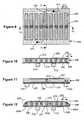
- Figure 9is a schematic diagram of a top view of an illustrative normally closed valve in accordance with the present invention.
- Figure 10is a front view taken along 10-10 of Figure 9, and
- Figure 11is a side view taken along 11-11 of Figure 9 .
- the illustrative embodiment shown in Figures 9-11includes a housing 208 that defines a cavity 214, with an inlet 210 and an outlet 212 extending into the cavity 214.
- a fluid pathsuch as fluid path 215, is selectively provided between the inlet 210 and outlet 212 through the cavity 214.
- a diaphragm 230is positioned in the cavity 214, wherein at least part of the diaphragm 230 defines at least part of the fluid path 215.
- the diaphragm 230is positioned between two opposing sides 211 and 213 of the cavity 214.
- a number of diaphragm electrodes 220are fixed relative to the diaphragm 230 as shown.
- the diaphragm electrodes 220are spaced side-by-side in a spacing direction 217 along at least part of the diaphragm 230.
- the flow path 215extends normal (e.g. into the page in Figure 10 ) or substantially normal to the spacing direction 217.
- a housing electrode 222may be fixed relative to opposing side 213 of housing 208. While only one housing electrode 222 is shown in Figure 10 , it is contemplated that more than one housing electrode 222 may be provided, if desired.
- at least one biasing element 235is provided between the number of diaphragm electrodes 220 and the housing electrode 222, as shown.
- each biasing element 235may include a spring.
- the biasing elementmay be any suitable biasing means that is capable of biasing the diaphragm 230 toward opposing side 211 of cavity - in the normally closed valve configuration.
- the biasing meansmay simply be the elastic properties of the diaphragm 230 itself. That is, the diaphragm 230 may be mounted (and possibly stretched) directly adjacent to the opposing side 211 of cavity. The diaphragm 230 may then return to this position by elastic restoring forces when the electrodes are not activated.
- diaphragm electrodes 220there are nine diaphragm electrodes 220 each with a biasing element 235. It is contemplated, however, that there may be any number of diaphragm electrodes 220. It is also contemplated, that there may be any number of biasing elements 235 between the diaphragm electrode 220 and the housing electrode 222, as desired.
- the biasing elements 235exert a force between the number of diaphragm electrodes 220 and the housing electrode 222.
- the biasing forcehelps push the diaphragm 230 towards the housing wall 211 pinching off the flow path 215 through the cavity -214.
- a voltageis applied between the housing electrode 222 and one or more of the diaphragm electrodes 220, a force is generated between the housing electrode 222 and the activated diaphragm electrodes 220, which overcomes the biasing force provided by the corresponding biasing elements 235.
- the portion of the diaphragm that corresponds to the selected diaphragm electrodes 220may be electrostatically pulled toward the housing electrode 222, thereby opening part of the flow path 215 through cavity 214. That is, by electrostatically pulling part of the diaphragm 230 toward the opposing side 213, the cross-sectional area of the flow path 215 may be increased, which may modulate the fluid flow from the inlet 210 to the outlet 212 of the
- a minimum fluid flow(in some cases no fluid flow) may be achieved between the inlet 210 and the outlet 212 of the valve. If one of the diaphragm electrodes 220 is electrostatically pulled toward the opposing side 213 overcoming the corresponding biasing element, an increased fluid flow may be achieved between the inlet 210 and the outlet 212 of the valve. If two of the diaphragm electrodes 220 are electrostatically pulled toward the opposing side 213, an even further increase in fluid flow may be achieved between the inlet 210 and the outlet 212 of the valve, and so on.
- a desired resolution in the modulated fluid flow through the valvemay be achieved.
- at least three stable diaphragm positionsare provided, wherein fluid can flow from the inlet 210 to the outlet 212 in at least two of the stable positions.
- One stable diaphragm 230 positionmay be fully closed, one may be fully open, and yet another may be partially open.
- the opposing wall 213may be curved toward the diaphragm 230 at one or more regions, such as regions 240. Since the electrostatic force that is generated at a given voltage is inversely proportional to the distance between the electrodes, such a construction may help reduce the voltage required to initially pull the diaphragm 230 toward the opposing wall 213, at least in the regions 240.
- a controllermay initially provide a voltage between diaphragm electrodes 220a and housing electrode 223. This may pull the ends of the diaphragm 230 toward the opposing wall 213 overcoming the corresponding biasing elements 235. This may also move the adjacent diaphragm electrodes 220 closer to the housing electrode 223, which may reduce the voltage that is required to pull the adjacent diaphragm electrodes 220 toward the housing electrode 223, when desired. As can be seen, this may result in a "rolling" action of the diaphragm 230 as each successive diaphragm electrode 220 is activated in sequence.
- Figure 13is a schematic diagram of a top view of an illustrative normally closed valve with binary patterned electrodes.
- Figure 14is a front view taken along 14-14 of Figure 13
- Figure 15is a side view taken along 15-15 of Figure 13 .
- the illustrative embodiment shown in Figures 13-15includes a housing 308 that defines a cavity 314, with an inlet 310 and an outlet 312 extending into the cavity 314.
- a fluid path, such as flow path 315,is selectively provided between the inlet 310 and outlet 312 through the cavity 314.
- a diaphragm 330is positioned in the cavity 314, wherein at least part of the diaphragm 330 defines at least part of the fluid path 315.
- the diaphragm 330is positioned between two opposing sides 311 and 313 of the cavity 314.
- a number of diaphragm electrodes 320are fixed relative to the diaphragm 330 as shown.
- the diaphragm electrodes 320are spaced side-by-side in a spacing direction 317 along at least part of the diaphragm 330.
- a biasing element 335is fixed between diaphragm 330 and the housing 308, as shown.
- the flow path 315extends normal (e.g. into the page in Figure 14 ) or substantially normal to the spacing direction 317.
- the diaphragm electrodes 324each have an electrode width along the spacing direction 317.
- the diaphragm electrodes 324have widths of 2 N , where N represents the electrode position, from left to right, in the particular series of diaphragm electrodes.
- the advantage of having diaphragm electrodes 324 of different widthsis the increase in the resulting range of flow areas that can be achieved.
- a housing electrode 322may be fixed relative to opposing side 313 of housing 308. While only one housing electrode 322 is shown in Figure 14 , it is contemplated that more than one housing electrode 322 may be provided, if desired. At least one biasing element 335 is positioned between the number of diaphragm electrodes 320 and the housing electrode 322. In one case, the biasing element 335 may include a spring, however, the biasing element may be any suitable biasing element as desired. As illustrated in Figure 14 , there are nine diaphragm electrodes 320 each with one or more biasing element. It is contemplated, however, that there may be any number of diaphragm electrodes 320. It is also contemplated, that there may be more than one biasing elements 335 for each diaphragm electrodes 320 as desired.
- the biasing elements 335exert a force between the corresponding diaphragm electrodes 320 and the housing 308.
- the biasing forcepushes the diaphragm 330 towards the housing wall 311 pinching off the flow path 315 through the cavity 314.
- a voltageis applied between the housing electrode 322 and one or more selected diaphragm electrodes 320
- a forceis generated between the housing electrode 322 and the selected diaphragm electrodes 320 to overcome the biasing force.
- the portion of the diaphragm that corresponds to the selected diaphragm electrodes 320is electrostatically pulled toward the housing electrode 322, thereby opening part of the flow path 315 through cavity 314. That is, by electrostatically pulling part of the diaphragm 330 toward the opposing side 313, the cross-sectional area of the flow path 315 may be increased, which may modulate the fluid flow from the inlet 310 to the outlet 312 of the valve.
- a minimum fluid flow(in some cases no fluid flow) may be achieved between the inlet 310 and the outlet 312 of the valve. If one of the diaphragm electrodes 320 is electrostatically pulled toward the opposing side 313 overcoming the biasing means, an increased fluid flow may be achieved between the inlet 310 and the outlet 312 of the valve. If two of the diaphragm electrodes 320 are electrostatically pulled toward the opposing side 313, an even further increase in fluid flow may be achieved between the inlet 310 and the outlet 312 of the valve, and so on.
- a desired resolution in the modulated fluid flow through the valvemay be achieved.
- at least three stable diaphragm positionsare provided, wherein fluid can flow from the inlet 310 to the outlet 312 in at least two of the stable positions.
- the opposing wall 313may be curved toward the diaphragm 330 at one or more regions, such as regions 340. Since the electrostatic force that is generated at a given voltage is inversely proportional to the distance between the electrodes, such a construction may help reduce the voltage required to initially pull the diaphragm 330 toward the opposing wall 313, at least in the regions 340.
- Figure 17is a schematic diagram of a cross-sectional view of a normally open valve including fluid flow valleys.
- the illustrative embodimentincludes a housing 408, with an inlet 412 and outlet 412 extending into the cavity 414.
- a diaphragm 430is positioned in the cavity 414, wherein at least part of the diaphragm 430 defines at least part of the fluid path.
- the housing wall 429has a corrugated surface having alternating ridges 431 and groves 432.
- a number of diaphragm electrodes 420are fixed relative to the diaphragm 430 as shown.
- the diaphragm electrodes 420are spaced relative to the corrugated surface of the housing wall 429. It is contemplated that the width of the ridges 431 and groves 432 may be any width as desired and that the corresponding one or more diaphragm electrodes 420 may have a similar width.
- the diaphragm electrodes 420 and the corrugated surfaceform fluid "flow valleys.”
- the portion of the diaphragm 430 that corresponds to the selected diaphragm electrodes 420may be electrostatically pulled toward the housing electrode, thereby pinching off at least part of the flow valley through cavity 414 to modulate the flow.
- the advantage of having individual fluid flow valleys for each diaphragm electrode 420is that as the diaphragm 430 is pulled toward housing wall 429, the corrugated surface may provide a better seal of the cavity 414. Thus, the leakage of the valve may be decreased.
- This embodimentmay be incorporated with any of the previous embodiments to improve the performance of the valves.
- Figure 18is a schematic diagram of a side view of an illustrative valve seat.
- Figure 19is a front view of the embodiment in Figure 18 .
- the illustrative embodiment shown in Figures 18 and 19includes a housing 608 that defines a cavity 614, with an inlet 610 and outlet 612.
- a diaphragm 640is position in the cavity 614, wherein at least part of the diaphragm 630 defines part of the fluid path.
- a number of diaphragm electrodes 620are fixed relative to the diaphragm 630.
- the diaphragm electrodesare spaced side-by-side in a spacing direction 617 along at least part of the diaphragm 630.
- a bias elementis fixed between diaphragm 630 and the housing 408.
- the bias element 635may be a spring or any other suitable bias means, as desired.
- outlet 612extends into the cavity.
- At least one diaphragm electrode 625is a "valve seat” electrode.
- the one or more valve seat electrode 625is situated over the outlet 612.
- the one or more valve seat electrode 625is biased to push the diaphragm 630 over the outlet 612 to form a seal.
- the one or more valve seat electrode 625may help control the opening and closing of the valve.
- the other diaphragm electrodes 620may be used to modulate the flow of the fluid through the cavity 614 when the valve is open.
- the diaphragmis pulled toward the housing electrode 422 opening the outlet 612 allowing fluid to flow.
- the part of the diaphragm corresponding to the selected diaphragm electrodes 620is pulled toward the housing electrode 422, thereby modulating the flow of fluid from the inlet 610 to the outlet 612.
- This embodimentmay used in conjunction with any of the previous embodiments.
- Figure 20is a schematic diagram of a side view of a normally open valve that can increase or decrease the size of the cavity 514.
- Figure 21is a schematic diagram of Figure 20 , with the diaphragm activated in a partially open position.
- the illustrative embodimentincludes a housing 508 that defines a cavity 514, with an inlet 510 and outlet 512 extending into the cavity 514.
- a diaphragm 530is positioned in the cavity 514, wherein at least part of the diaphragm defines at least part of the fluid path.
- the diaphragm 530is positioned between the two opposing sides of the cavity 511 and 513.
- a number of diaphragm electrodes 520are fixed relative to the diaphragm 530 as shown.
- the diaphragm electrodes 520are spaced along 517 of the diaphragm 530.
- the opposing cavity walls 511 and 513each have housing electrodes 522 and 526 fixed to them.
- the housing electrodes 522 and 526are shown similarly spaced along 517 as the diaphragm electrodes. It is contemplated that the diaphragm electrodes 520 and the housing electrodes 522 and 526 may be any width or spacing, as desired. Also, it is contemplated that the housing electrodes 522 and 526 may be continuous electrodes, as shown by dotted lines 540 and 542, rather than spaced electrodes. Alternatively, the housing electrodes 522 and 526 may be spaced electrodes, and the diaphragm electrodes 520 may be a continuous electrode, if desired.
- a voltagemay be applied to one or more selected diaphragm electrodes 520 and one or more housing electrodes 522 and 526.
- a voltageis applied to one or more selected diaphragm electrodes 520 and one or more selected housing electrodes 522, the part of the diaphragm 530 corresponding to the diaphragm electrode 520 may be electrostatically pulled toward the housing electrode 522, thereby increasing the flow path of the cavity 514.
- the part of the diaphragm 530 corresponding to the selected diaphragm electrode 520may be electrostatically pulled toward the housing electrode 526, thereby decreasing the size of the flow path.
- one or more housing electrodes 522 and one or more housing electrodes 526may be actuated at the same time pulling part of the diaphragm 530 up and pulling another part of the diaphragm 530 down, as shown in Figure 21 .
- a selected diaphragm electrode 520may be actuated with either corresponding housing electrode 522 or 526.
- the flowcan be modulated to increase or decrease the fluid flow in the cavity 514.
- a positive voltagesuch as +A volts may be applied to the upper housing electrode 522
- a negative voltagesuch as -A volts may be applied to the lower housing electrode 526.
- the diaphragm electrodes 520may be a zero volts.
- a positive voltagesuch as +A volts
- a negative voltagesuch as -A volts, may be applied to one or more selected diaphragm electrodes 520 to move the corresponding diaphragm electrodes 520 toward the +A voltage of the upper housing electrode 522.
Landscapes
- Engineering & Computer Science (AREA)
- General Engineering & Computer Science (AREA)
- Mechanical Engineering (AREA)
- Chemical & Material Sciences (AREA)
- Dispersion Chemistry (AREA)
- Computer Hardware Design (AREA)
- Microelectronics & Electronic Packaging (AREA)
- Theoretical Computer Science (AREA)
- Physics & Mathematics (AREA)
- Fluid Mechanics (AREA)
- Electrically Driven Valve-Operating Means (AREA)
- Micromachines (AREA)
Abstract
Description
- The present invention generally relates to modulating valves, and more particularly, to microfluidic modulating valves that can selectively modulate the size of a flow channel.
- Many modern industrial, commercial, aerospace, military and medical systems depend on reliable valves for fluid handling. The trends in fluid handling systems are toward smaller, more distributed and more portable systems for increasing uses in instrumentation and control. For example, microfluidic devices have become popular in such applications as analytical testing. In many cases, microfluidic devices are constructed in a multi-layer, often laminated, structure where each layer has channels and structures fabricated from a laminate material to form microscale voids or channels where fluids flow. The control and pumping of fluids through these channels is often affected by either external pressurized fluid forced into the laminate, or by structures located within the microfluidic device.
- Many different types of valves for use in controlling fluids in such microscale devices have been developed. Many of these valves, however, are on-off type valves, and do not allow for the fluid flow to be modulated. What would be desirable, therefore, is a microfluidic modulating valve that can selectively modulate the size of a flow channel to allow for the fluid flow to be selectively modulated.
US Patent Specification 6089534 discloses a valve with a diaphragm positioned in a cavity, part of the diaphragm defining a fluid path between the inlet and outlet ports.- The present invention provides a valve as defined in Claim 1. The valve may include the features of any one or more of
dependent claims 2 to 4. - The present invention also provides a method as defined in Claim 5.
- The following summary of the invention is provided to facilitate an understanding of some of the innovative feature unique to the present invention and is not intended to be a full description. A full appreciation of the invention can be gained by taking the entire specification, claims, drawings, and abstract as a whole.
- The present invention generally relates to modulating valves, and more particularly, to electrostatically actuated microfluidic modulating valves that can selectively change the size of a flow channel in order to modulate the fluid flow through the valve. In one illustrative embodiment, a valve is provided that includes a housing that defines a cavity, with an inlet and an outlet extending into the cavity. A diaphragm is positioned in the cavity, where at least part of the diaphragm defines at least part of the fluid path. One or more electrodes are fixed relative to the diaphragm, and one or more electrodes are fixed relative to the housing such that the diaphragm can be electrostatically actuated between at least three stable positions, wherein each stable position results in a different cross-sectional area of the fluid path. In some embodiments, the various stable positions provide a cross-sectional area such that fluid can flow between the inlet port and the outlet port in at least two of the stable positions.
- In some illustrative embodiments, the valve includes at least two independently controllable diaphragm electrodes fixed relative to the diaphragm, and at least one housing electrode fixed relative to the housing. When a sufficient voltage is applied between a first one of the diaphragm electrodes and the one or more housing electrode, at least part of the diaphragm is actuated to provide a first cross-sectional area for the fluid path. When a sufficient voltage is applied between a second one of the diaphragm electrodes (or a different combination of diaphragm electrodes) and one or more housing electrode, at least part of the diaphragm is actuated to provide a second cross-sectional area of the fluid path, wherein the first cross-sectional area is different from the second cross-sectional area.
- In some embodiments, the valve may include at least two housing electrodes fixed relative to a first one of two opposing sides of the cavity that includes the diaphragm, and at least two housing electrodes fixed relative to a second one of the two opposing sides of the cavity. In addition, the diaphragm includes at least two diaphragm electrodes fixed relative to the diaphragm, wherein at least selected diaphragm electrodes are adjacent to and generally aligned with two corresponding housing electrode; one on the first side of the cavity and the other on the second side of the cavity. When a sufficient voltage is applied between one or more of the diaphragm electrodes and one or more of the corresponding housing electrodes, at least part of the diaphragm is pulled toward the housing electrode. When a sufficient voltage is applied between different ones of the diaphragm electrodes and the other corresponding housing electrode, at least part of the diaphragm is pulled toward the different housing electrode. This may allow the cross-sectional area of the fluid path to be actively controlled. When multiple diaphragm electrodes/housing electrodes are controlled in this manner, the shape of the diaphragm, and thus the cross-sectional area of the fluid path, may be modulated over a relatively wide range.
Figure 1 is a schematic diagram of a top view of an illustrative normally open valve with equal area electrodes;Figure 2 is a schematic diagram of a front view of the illustrative embodiment ofFigure 1 ;Figure 3 is a schematic diagram of the side view of the illustrative embodiment ofFigure 1 ;Figure 4 is a schematic diagram of an alternative to the illustrative embodiment ofFigure 2 having the edges of the second electrode curve toward the diaphragm;Figure 5 is a schematic diagram of a top view of an illustrative normally open valve with binary patterned electrodes;Figure 6 is a schematic diagram of a front view of the illustrative embodiment ofFigure 5 ;Figure 7 is a schematic diagram of a side view of the illustrative embodiment ofFigure 5 ;Figure 8 is a schematic diagram of an alternative to the illustrative embodiment ofFigure 6 having the edges of the second electrode curve toward the diaphragm;Figure 9 is a schematic diagram of a top view of an illustrative normally closed valve with equal area electrodes;Figure 10 is a schematic diagram of a front view of the illustrative embodiment ofFigure 9 ;Figure 11 is a schematic diagram of a side view of the illustrative embodiment ofFigure 9 ;Figure 12 is a schematic diagram of an alternative to the illustrative embodiment ofFigure 10 having the edges of the second electrode curve toward the diaphragm;Figure 13 is a schematic diagram of a top view of an illustrative normally closed valve with binary patterned electrodes;Figure 14 is a schematic diagram of a front view of the illustrative embodiment ofFigure 13 ;Figure 15 is a schematic diagram of a side view of the illustrative embodiment ofFigure 13 ;Figure 16 is a schematic diagram of an alternative to the illustrative embodiment ofFigure 14 having the edges of the second electrode curve toward the diaphragm;Figure 17 is a schematic diagram of a front view of an illustrative valve including fluid flow valleys;Figure 18 is a schematic diagram of a side view of an illustrative valve seat;Figure 19 is a schematic diagram of a front view of the illustrative embodiment inFigure 18 ;Figure 20 is a schematic diagram of a front view of an illustrative normally open valve that can increase or decrease the size of the flow chamber; andFigure 21 is a schematic diagram ofFigure 20 , with the diaphragm activated in a partially open position.- The following description should be read with reference to the drawings wherein like reference numerals indicate like elements throughout the several views. The detailed description and drawings show several embodiments which are meant to be illustrative of the claimed invention.
- The present invention generally relates to modulating valves, and more particularly, to electrostatically actuated microfluidic modulating valves that can selectively change the size of a flow channel in order to help modulate the fluid flow through the valve. The term "fluid" as used herein includes liquids and/or gasses, as desired.
- A first illustrative embodiment is shown in
Figures 1, 2, and 3. Figure 1 is a schematic diagram of a top view of an illustrative normally open valve in accordance with the present invention.Figure 2 is a front view taken along 2-2 ofFigure 1, and Figure 3 is a side view taken along 3-3 ofFigure 1 . - The illustrative embodiment shown in
Figures 1-3 includes ahousing 8 that defines acavity 14, with aninlet 10 and anoutlet 12 extending into thecavity 14. A fluid path, such asfluid path 15, is selectively provided between theinlet 10 andoutlet 12 through thecavity 14. Adiaphragm 30 is positioned in thecavity 14, wherein at least part of thediaphragm 30 defines at least part of thefluid path 15. In the illustrative embodiment, thediaphragm 30 is positioned between two opposingsides cavity 14. A number ofdiaphragm electrodes 20 are fixed relative to thediaphragm 30 as shown. Thediaphragm electrodes 20 are spaced side-by-side in aspacing direction 17 along at least part of thediaphragm 30. In the illustrative embodiment, theflow path 15 extends normal (e.g. into the page inFigure 2 ) or substantially normal to thespacing direction 17. - Specifically with reference to the illustrative embodiment of
Figure 2 , ahousing electrode 22 is fixed relative to opposingside 11 ofhousing 8. While only onehousing electrode 22 is shown inFigure 2 , it is contemplated that more than onehousing electrode 22 may be provided, if desired. When a voltage is applied between thehousing electrode 22 and one or moreselected diaphragm electrodes 20, the portion of the diaphragm that corresponds to the selecteddiaphragm electrodes 20 may be electrostatically pulled toward the housing electrode, thereby pinching off part of theflow path 15 throughcavity 14. That is, by electrostatically pulling part of thediaphragm 30 toward the opposingside 11, the cross-sectional area of theflow path 15 may be reduced, which may modulate the fluid flow from theinlet 10 to theoutlet 12 of the valve. In the illustrative embodiment, thediaphragm 30 may return to its un-activated position through elastic restoring forces. - In the illustrative embodiment, nine
diaphragm electrodes 20 are shown. It is contemplated, however, that any suitable number ofdiaphragm electrodes 20 may be used, as desired. If none of thediaphragm electrodes 20 are electrostatically activated and pulled toward the opposingside 11, a maximum fluid flow cross-sectional area may be achieved between theinlet 10 and theoutlet 12 of the valve. If one of thediaphragm electrodes 20 is electrostatically pulled toward the opposingside 11, a reduced fluid flow cross-sectional may be achieved between theinlet 10 and theoutlet 12 of the valve. If two of thediaphragm electrodes 20 are electrostatically pulled toward the opposingside 11, an even further reduction in fluid flow cross-sectional area may be achieved between theinlet 10 and theoutlet 12 of the valve, and so on. As can be seen, and depending on the number ofdiaphragm electrodes 20 that are provided and activated, a desired resolution in the modulated fluid flow through the valve may be achieved. In some illustrative embodiments, at least three stable diaphragm positions are provided, wherein fluid can flow from theinlet 10 to theoutlet 12 in at least two of the stable positions. - The
diaphragm electrodes 20 may be fixed to thediaphragm 30 and the housing electrode(s) 22 may be fixed to thehousing 8 in any suitable manner. For example, thediaphragm electrodes 20 may be deposited on the diaphragm by evaporation or sputter deposition, doping thediaphragm 30 to be conductive in certain regions, screen printing a conductive material on the diaphragm, adhered an electrode pattern to thediaphragm 30, or in any other suitable manner. The one ormore housing electrodes 22 may be provided in a different or similar manner, as desired. In some cases, part of all of the diaphragm or housing may be made from a conductive material, and may perform dual functions (e.g. as a housing and as an electrode), if desired. - In some cases, a dielectric layer may be provided over the
diaphragm electrodes 20 and/or the housing electrode(s) 22. This may help prevent an electrical short between the diaphragm electrodes and the one or more housing electrodes when the diaphragm is pulled toward the housing electrodes during operation. The dielectric layer may also help protect the diaphragm electrodes and the one or more housing electrode(s) from the environment, and may further help prevent stiction. - To help reduce the voltage that may be required to begin closing the valve, and with reference to
Figure 4 , it is contemplated the opposingwall 11 may be curved toward the diaphragm at one or more regions, such as inregions 40. Since the electrostatic force that is generated at a given voltage is inversely proportional to the distance between the electrodes, such a construction may help reduce the voltage required to initially pull thediaphragm 30 toward the opposingwall 11, at least in theregions 40. During operation of the valve shown inFigure 4 , a controller may initially provide a voltage betweendiaphragm electrode 20a andhousing electrode 23. This may pull the ends of the diaphragm down toward the opposingwall 11. This may also move the adjacent diaphragm electrodes closer to thehousing electrode 23, which may also reduce the voltage that is required to pull the adjacent diaphragm electrodes toward thehousing electrode 23, when desired. As can be seen, this may result in a "rolling" action of thediaphragm 30 as each successive diaphragm electrode is activated in sequence. - Another illustrative embodiment is shown in
Figures 5, 6, and 7. Figure 5 is a schematic diagram of a top view of an illustrative normally open valve with binary patterned electrodes.Figure 6 is a front view taken along 6-6 ofFigure 5, and Figure 7 is a side view taken along 7-7 ofFigure 5 . - Similar to the previous illustrative embodiment, the illustrative embodiment shown in
Figures 5-8 includes ahousing 108 that defines acavity 114, with aninlet 110 and anoutlet 112 extending into thecavity 114. A fluid path, such asfluid path 115, is selectively provided between theinlet 110 andoutlet 112 through thecavity 114. Adiaphragm 130 is positioned in thecavity 114, wherein at least part of thediaphragm 130 defines at least part of thefluid path 115. In the illustrative embodiment, thediaphragm 130 is positioned between two opposingsides cavity 114. A number ofdiaphragm electrodes 124 are fixed relative to thediaphragm 130 as shown. Thediaphragm electrodes 124 are spaced side-by-side in aspacing direction 117 along at least part of thediaphragm 130. In the illustrative embodiment, theflow path 115 extends normal (e.g. into the page inFigure 6 ) or substantially normal to thespacing direction 117. - The
diaphragm electrodes 124 each have an electrode width along thespacing direction 117. In the illustrative embodiment, thediaphragm electrodes 124 have widths of 2N, where N represents the electrode position, from left to right, in the particular series of diaphragm electrodes. The advantage of havingdiaphragm electrodes 124 of different widths (e.g. 2N) is the increase in the resulting range of flow areas that can be achieved. As shown in the illustrative embodiment, there are fivediaphragm electrodes 124. By activating different combinations of diaphragm electrodes, the five diaphragm electrodes may provide thirty-two combinations of different fluid flow areas. It is contemplated, however, that any suitable width of thediaphragm electrodes 124 may be used or any suitable number ofdiaphragm electrodes 124 may be used, as desired. - Similar as discussed above, one or more housing electrode(s) 122 may be fixed relative to opposing
side 111 of thehousing 108. When a voltage is applied between thehousing electrode 122 and selecteddiaphragm electrodes 124, the portion of thediaphragm 130 that corresponds to the selecteddiaphragm electrodes 124 may be electrostatically pulled toward thehousing electrode 122, thereby pinching off part of theflow path 115 throughcavity 114. - To help reduce the voltage that may be required to begin closing the valve, and with reference to
Figure 8 , it is contemplated the opposingwall 11 may be curved toward thediaphragm 130 at one or more regions, such as inregions 140, as discussed above. Since the electrostatic force that is generated at a given voltage is inversely proportional to the distance between the electrodes, such a construction may help reduce the voltage required to initially pull thediaphragm 130 toward the opposingwall 111, at least in theregions 140. - A third illustrative embodiment is shown in
Figures 9, 10, and 11. Figure 9 is a schematic diagram of a top view of an illustrative normally closed valve in accordance with the present invention.Figure 10 is a front view taken along 10-10 ofFigure 9, and Figure 11 is a side view taken along 11-11 ofFigure 9 . - The illustrative embodiment shown in
Figures 9-11 includes ahousing 208 that defines acavity 214, with aninlet 210 and anoutlet 212 extending into thecavity 214. A fluid path, such asfluid path 215, is selectively provided between theinlet 210 andoutlet 212 through thecavity 214. Adiaphragm 230 is positioned in thecavity 214, wherein at least part of thediaphragm 230 defines at least part of thefluid path 215. In the illustrative embodiment, thediaphragm 230 is positioned between two opposingsides cavity 214. A number ofdiaphragm electrodes 220 are fixed relative to thediaphragm 230 as shown. Thediaphragm electrodes 220 are spaced side-by-side in aspacing direction 217 along at least part of thediaphragm 230. In the illustrative embodiment, theflow path 215 extends normal (e.g. into the page inFigure 10 ) or substantially normal to thespacing direction 217. - Specifically with reference to
Figure 10 , ahousing electrode 222 may be fixed relative to opposingside 213 ofhousing 208. While only onehousing electrode 222 is shown inFigure 10 , it is contemplated that more than onehousing electrode 222 may be provided, if desired. In the illustrative embodiment, at least one biasingelement 235 is provided between the number ofdiaphragm electrodes 220 and thehousing electrode 222, as shown. In one case, each biasingelement 235 may include a spring. However, the biasing element may be any suitable biasing means that is capable of biasing thediaphragm 230 toward opposingside 211 of cavity - in the normally closed valve configuration. In some cases, the biasing means may simply be the elastic properties of thediaphragm 230 itself. That is, thediaphragm 230 may be mounted (and possibly stretched) directly adjacent to the opposingside 211 of cavity. Thediaphragm 230 may then return to this position by elastic restoring forces when the electrodes are not activated. - As illustrated in
Figure 10 , there are ninediaphragm electrodes 220 each with a biasingelement 235. It is contemplated, however, that there may be any number ofdiaphragm electrodes 220. It is also contemplated, that there may be any number of biasingelements 235 between thediaphragm electrode 220 and thehousing electrode 222, as desired. - The biasing
elements 235 exert a force between the number ofdiaphragm electrodes 220 and thehousing electrode 222. The biasing force helps push thediaphragm 230 towards thehousing wall 211 pinching off theflow path 215 through the cavity -214. When a voltage is applied between thehousing electrode 222 and one or more of thediaphragm electrodes 220, a force is generated between thehousing electrode 222 and the activateddiaphragm electrodes 220, which overcomes the biasing force provided by the corresponding biasingelements 235. Thus, the portion of the diaphragm that corresponds to the selecteddiaphragm electrodes 220 may be electrostatically pulled toward thehousing electrode 222, thereby opening part of theflow path 215 throughcavity 214. That is, by electrostatically pulling part of thediaphragm 230 toward the opposingside 213, the cross-sectional area of theflow path 215 may be increased, which may modulate the fluid flow from theinlet 210 to theoutlet 212 of the valve. - If none of the
diaphragm electrodes 220 are electrostatically pulled toward the opposingside 213, a minimum fluid flow (in some cases no fluid flow) may be achieved between theinlet 210 and theoutlet 212 of the valve. If one of thediaphragm electrodes 220 is electrostatically pulled toward the opposingside 213 overcoming the corresponding biasing element, an increased fluid flow may be achieved between theinlet 210 and theoutlet 212 of the valve. If two of thediaphragm electrodes 220 are electrostatically pulled toward the opposingside 213, an even further increase in fluid flow may be achieved between theinlet 210 and theoutlet 212 of the valve, and so on. As can be seen, and depending on the number ofdiaphragm electrodes 220 that are provided and activated, a desired resolution in the modulated fluid flow through the valve may be achieved. In some illustrative embodiments, at least three stable diaphragm positions are provided, wherein fluid can flow from theinlet 210 to theoutlet 212 in at least two of the stable positions. Onestable diaphragm 230 position may be fully closed, one may be fully open, and yet another may be partially open. - To help reduce the voltage that may be required to begin closing the valve, and with reference to
Figure 12 , it is contemplated the opposingwall 213 may be curved toward thediaphragm 230 at one or more regions, such asregions 240. Since the electrostatic force that is generated at a given voltage is inversely proportional to the distance between the electrodes, such a construction may help reduce the voltage required to initially pull thediaphragm 230 toward the opposingwall 213, at least in theregions 240. - During operation of the valve shown in
Figure 12 , a controller may initially provide a voltage betweendiaphragm electrodes 220a andhousing electrode 223. This may pull the ends of thediaphragm 230 toward the opposingwall 213 overcoming thecorresponding biasing elements 235. This may also move theadjacent diaphragm electrodes 220 closer to thehousing electrode 223, which may reduce the voltage that is required to pull theadjacent diaphragm electrodes 220 toward thehousing electrode 223, when desired. As can be seen, this may result in a "rolling" action of thediaphragm 230 as eachsuccessive diaphragm electrode 220 is activated in sequence. - A fourth illustrative embodiment is shown in
Figures 13, 14, and 15. Figure 13 is a schematic diagram of a top view of an illustrative normally closed valve with binary patterned electrodes.Figure 14 is a front view taken along 14-14 ofFigure 13, and Figure 15 is a side view taken along 15-15 ofFigure 13 . - Similar to the previous embodiment, the illustrative embodiment shown in
Figures 13-15 includes ahousing 308 that defines a cavity 314, with aninlet 310 and anoutlet 312 extending into the cavity 314. A fluid path, such asflow path 315, is selectively provided between theinlet 310 andoutlet 312 through the cavity 314. Adiaphragm 330 is positioned in the cavity 314, wherein at least part of thediaphragm 330 defines at least part of thefluid path 315. In the illustrative embodiment, thediaphragm 330 is positioned between two opposingsides diaphragm 330 as shown. The diaphragm electrodes 320 are spaced side-by-side in aspacing direction 317 along at least part of thediaphragm 330. A biasingelement 335 is fixed betweendiaphragm 330 and thehousing 308, as shown. In the illustrative embodiment, theflow path 315 extends normal (e.g. into the page inFigure 14 ) or substantially normal to thespacing direction 317. - The
diaphragm electrodes 324 each have an electrode width along thespacing direction 317. In the illustrative embodiment, thediaphragm electrodes 324 have widths of 2N, where N represents the electrode position, from left to right, in the particular series of diaphragm electrodes. The advantage of havingdiaphragm electrodes 324 of different widths (e.g. 2N) is the increase in the resulting range of flow areas that can be achieved. As shown in the illustrative embodiment, there are fivediaphragm electrodes 324. By activating different combinations ofdiaphragm electrodes 324, the five diaphragm electrodes may provide thirty-two combinations of different fluid flow areas. It is contemplated, however, that any suitable width of thediaphragm electrodes 324 may be used or any suitable number ofdiaphragm electrodes 324 may be used, as desired. - Specifically with reference to
Figure 14 , ahousing electrode 322 may be fixed relative to opposingside 313 ofhousing 308. While only onehousing electrode 322 is shown inFigure 14 , it is contemplated that more than onehousing electrode 322 may be provided, if desired. At least one biasingelement 335 is positioned between the number of diaphragm electrodes 320 and thehousing electrode 322. In one case, the biasingelement 335 may include a spring, however, the biasing element may be any suitable biasing element as desired. As illustrated inFigure 14 , there are nine diaphragm electrodes 320 each with one or more biasing element. It is contemplated, however, that there may be any number of diaphragm electrodes 320. It is also contemplated, that there may be more than one biasingelements 335 for each diaphragm electrodes 320 as desired. - The biasing
elements 335 exert a force between the corresponding diaphragm electrodes 320 and thehousing 308. The biasing force pushes thediaphragm 330 towards thehousing wall 311 pinching off theflow path 315 through the cavity 314. When a voltage is applied between thehousing electrode 322 and one or more selected diaphragm electrodes 320, a force is generated between thehousing electrode 322 and the selected diaphragm electrodes 320 to overcome the biasing force. The portion of the diaphragm that corresponds to the selected diaphragm electrodes 320 is electrostatically pulled toward thehousing electrode 322, thereby opening part of theflow path 315 through cavity 314. That is, by electrostatically pulling part of thediaphragm 330 toward the opposingside 313, the cross-sectional area of theflow path 315 may be increased, which may modulate the fluid flow from theinlet 310 to theoutlet 312 of the valve. - If none of the diaphragm electrodes 320 are electrostatically pulled toward the opposing
side 313, a minimum fluid flow (in some cases no fluid flow) may be achieved between theinlet 310 and theoutlet 312 of the valve. If one of the diaphragm electrodes 320 is electrostatically pulled toward the opposingside 313 overcoming the biasing means, an increased fluid flow may be achieved between theinlet 310 and theoutlet 312 of the valve. If two of the diaphragm electrodes 320 are electrostatically pulled toward the opposingside 313, an even further increase in fluid flow may be achieved between theinlet 310 and theoutlet 312 of the valve, and so on. As can be seen, and depending on the number and type of diaphragm electrodes 320 that are provided and activated, a desired resolution in the modulated fluid flow through the valve may be achieved. In some illustrative embodiments, at least three stable diaphragm positions are provided, wherein fluid can flow from theinlet 310 to theoutlet 312 in at least two of the stable positions. - To help reduce the voltage that may be required to begin closing the valve, and with reference to
Figure 16 , it is contemplated the opposingwall 313 may be curved toward thediaphragm 330 at one or more regions, such asregions 340. Since the electrostatic force that is generated at a given voltage is inversely proportional to the distance between the electrodes, such a construction may help reduce the voltage required to initially pull thediaphragm 330 toward the opposingwall 313, at least in theregions 340. - Another illustrative embodiment is shown in
Figures 17. Figure 17 is a schematic diagram of a cross-sectional view of a normally open valve including fluid flow valleys. The illustrative embodiment includes ahousing 408, with an inlet 412 and outlet 412 extending into thecavity 414. Adiaphragm 430 is positioned in thecavity 414, wherein at least part of thediaphragm 430 defines at least part of the fluid path. Thehousing wall 429 has a corrugated surface having alternatingridges 431 andgroves 432. A number ofdiaphragm electrodes 420 are fixed relative to thediaphragm 430 as shown. Thediaphragm electrodes 420 are spaced relative to the corrugated surface of thehousing wall 429. It is contemplated that the width of theridges 431 andgroves 432 may be any width as desired and that the corresponding one ormore diaphragm electrodes 420 may have a similar width. A housing electrode - (not shown) may be fixed to the corrugated surface of the
housing wall 429. Thediaphragm electrodes 420 and the corrugated surface form fluid "flow valleys." - When a voltage is applied between the housing electrode (not shown) and one or more
selected diaphragm electrodes 420, the portion of thediaphragm 430 that corresponds to the selecteddiaphragm electrodes 420 may be electrostatically pulled toward the housing electrode, thereby pinching off at least part of the flow valley throughcavity 414 to modulate the flow. The advantage of having individual fluid flow valleys for eachdiaphragm electrode 420 is that as thediaphragm 430 is pulled towardhousing wall 429, the corrugated surface may provide a better seal of thecavity 414. Thus, the leakage of the valve may be decreased. This embodiment may be incorporated with any of the previous embodiments to improve the performance of the valves. - Another illustrative embodiment is shown in
Figures 18 and 19. Figure 18 is a schematic diagram of a side view of an illustrative valve seat.Figure 19 is a front view of the embodiment inFigure 18 . - The illustrative embodiment shown in
Figures 18 and 19 includes ahousing 608 that defines acavity 614, with aninlet 610 andoutlet 612. A diaphragm 640 is position in thecavity 614, wherein at least part of thediaphragm 630 defines part of the fluid path. A number ofdiaphragm electrodes 620 are fixed relative to thediaphragm 630. The diaphragm electrodes are spaced side-by-side in aspacing direction 617 along at least part of thediaphragm 630. In the illustrative embodiment, a bias element is fixed betweendiaphragm 630 and thehousing 408. Thebias element 635 may be a spring or any other suitable bias means, as desired. In the illustrative embodiment,outlet 612 extends into the cavity. At least onediaphragm electrode 625, is a "valve seat" electrode. The one or morevalve seat electrode 625 is situated over theoutlet 612. The one or morevalve seat electrode 625 is biased to push thediaphragm 630 over theoutlet 612 to form a seal. - In operating the valve in the illustrative embodiment, the one or more
valve seat electrode 625 may help control the opening and closing of the valve. Theother diaphragm electrodes 620 may be used to modulate the flow of the fluid through thecavity 614 when the valve is open. When a voltage is applied to the one or morevalve seat electrode 625, the diaphragm is pulled toward the housing electrode 422 opening theoutlet 612 allowing fluid to flow. When a voltage is applied to theother diaphragm electrodes 620, the part of the diaphragm corresponding to the selecteddiaphragm electrodes 620 is pulled toward the housing electrode 422, thereby modulating the flow of fluid from theinlet 610 to theoutlet 612. This embodiment may used in conjunction with any of the previous embodiments. - Another illustrative embodiment is shown in
Figures 20 and 21. Figure 20 is a schematic diagram of a side view of a normally open valve that can increase or decrease the size of thecavity 514.Figure 21 is a schematic diagram ofFigure 20 , with the diaphragm activated in a partially open position. - The illustrative embodiment includes a
housing 508 that defines acavity 514, with aninlet 510 andoutlet 512 extending into thecavity 514. Adiaphragm 530 is positioned in thecavity 514, wherein at least part of the diaphragm defines at least part of the fluid path. Thediaphragm 530 is positioned between the two opposing sides of thecavity diaphragm electrodes 520 are fixed relative to thediaphragm 530 as shown. Thediaphragm electrodes 520 are spaced along 517 of thediaphragm 530. The opposingcavity walls housing electrodes housing electrodes diaphragm electrodes 520 and thehousing electrodes housing electrodes lines 540 and 542, rather than spaced electrodes. Alternatively, thehousing electrodes diaphragm electrodes 520 may be a continuous electrode, if desired. - To modulate the flow, a voltage may be applied to one or more
selected diaphragm electrodes 520 and one ormore housing electrodes selected diaphragm electrodes 520 and one or moreselected housing electrodes 522, the part of thediaphragm 530 corresponding to thediaphragm electrode 520 may be electrostatically pulled toward thehousing electrode 522, thereby increasing the flow path of thecavity 514. When a voltage is applied to one or moreselected diaphragm electrodes 520 and one or moreselected housing electrodes 526, the part of thediaphragm 530 corresponding to the selecteddiaphragm electrode 520 may be electrostatically pulled toward thehousing electrode 526, thereby decreasing the size of the flow path. - It is contemplated that one or
more housing electrodes 522 and one ormore housing electrodes 526 may be actuated at the same time pulling part of thediaphragm 530 up and pulling another part of thediaphragm 530 down, as shown inFigure 21 . However, a selecteddiaphragm electrode 520 may be actuated with eithercorresponding housing electrode cavity 514. - When the
housing electrodes lines 540 and 542, and in one illustrative embodiment, a positive voltage such as +A volts may be applied to theupper housing electrode 522, and a negative voltage such as -A volts may be applied to thelower housing electrode 526. Initially, thediaphragm electrodes 520 may be a zero volts. To modulate the flow, a positive voltage, such as +A volts, may be applied to one or moreselected diaphragm electrodes 520 to move thecorresponding diaphragm electrodes 520 toward the -A voltage of thelower housing electrode 526. Likewise, a negative voltage, such as -A volts, may be applied to one or moreselected diaphragm electrodes 520 to move thecorresponding diaphragm electrodes 520 toward the +A voltage of theupper housing electrode 522. - Having thus described the preferred embodiments of the present invention, those of skill in the art will readily appreciate that yet other embodiments may be made and used within the scope of the claims hereto attached. Numerous advantages of the invention covered by this document have been set forth in the foregoing description. It will be understood, however, that this disclosure is, in many respect, only illustrative. Changes may be made in details, particularly in matters of shape, size, and arrangement of parts without exceeding the scope of the invention. The invention's scope is, of course, defined in the language in which the appended claims are expressed.
Claims (5)
- A valve, comprising:a housing (8, 108, 208, 308, 408, 508, 608) that defines a cavity (14, 114, 214, 314, 414, 514, 614);an inlet port (10, 110, 210, 310, 410, 510, 610) in fluid communication with the cavity (14, 114, 214, 314, 414, 514, 614);an outlet port (12, 112, 212, 312, 412, 512, 612) in fluid communication with the cavity (14, 114, 214, 314, 414, 514, 614);a fluid path (15, 115, 215, 315) within the cavity (14, 114, 214, 314, 414, 514, 614) that extends between the inlet port (10, 110, 210, 310, 410, 510, 610) and the outlet port (12, 112, 212, 312, 412, S 12, 612), the fluid path (15, 115, 215, 315) having a cross-sectional area;a diaphragm (30, 130, 230, 330, 430, 530, 630) positioned in the cavity (14, 114, 214, 314, 414, 514, 614), at least part of the diaphragm (30, 130, 230, 330, 430, 530, 630) defining at least part of the fluid path (15, 115, 215, 315); andcharacterized byat least two independently controllable diaphragm electrodes (20, 124, 220, 324, 420, 520, 620) fixed relative to the diaphragm (30, 130, 230, 330, 430, 530, 630); andat least one housing electrode (22, 122, 222, 322, 432, 522, 622) fixed relative to the housing (8, 108, 208, 308, 408, 508, 608);the at least two diaphragm electrodes (20, 124, 220, 324, 420, 520, 620) and the at least one housing electrode (22, 122, 222, 322, 432, 522, 622) configured such that when a sufficient voltage is applied between a first one of the diaphragm electrodes (20, 124, 220, 324, 420, 520, 620) and the at least one housing electrode (22, 122, 222, 322, 432, 522, 622) at least part of the diaphragm (30, 130, 230, 330, 430, 530, 630) is actuated to provide a first cross-sectional area of the fluid path (15, 115, 215, 315), and when a sufficient voltage is applied between a second one of the diaphragm electrodes (20, 124, 220, 324, 420, 520, 620) and the at least one housing electrode (22, 122, 222, 322, 432, 522, 622) at least part of the diaphragm (30, 130, 230, 330, 430, 530, 630) is actuated to provide a second cross-sectional area of the fluid path (15, 115, 215, 315).
- The valve of claim 1 wherein the at least two independently controllable diaphragm electrodes (20, 124, 220, 324, 420, 520, 620) are spaced side-by-side in a spacing direction (17, 117, 217, 317, 417, 517, 617) along at least part of the diaphragm (30, 130, 230, 330, 430, 530, 630), each having an electrode width along the spacing direction (17, 117, 217, 317, 417, 517, 617), and at least two of the electrodes (20, 124, 220, 324, 420, 520, 620) have different electrode widths.
- The valve of claim 1 wherein the at least two independently controllable diaphragm electrodes (20, 124, 220, 324, 420, 520, 620) are spaced side-by-side in a spacing direction (17, 117, 217, 317, 417, 517, 617) along at least part of the diaphragm (30, 130, 230, 330, 430, 530, 630), each having an electrode width along the spacing direction (17, 117, 217, 317, 417, 517, 617), and wherein the at least two electrodes (20, 124, 220, 324, 420, 520, 620) have the same or substantially the same electrode widths.
- The valve of claim 1 further comprising a biasing element (235, 335, 635) for biasing the diaphragm (30, 130, 230, 330, 430, 530, 630) away from the at least one (22, 122, 222, 322, 432, 522, 622) housing electrode.
- A method of using a valve according to any one of claims 1-4 for modulating a fluid flow through a fluid path (15, 115, 215, 315), the method comprising the steps of:selecting a cross-sectional area for the fluid path (15, 115, 215, 315) from three or more discrete cross-sectional area values; andchanging the cross-sectional area for the fluid path (15, 115, 215, 315) to the selected one of the three or more discrete cross-sectional area values.
Applications Claiming Priority (2)
| Application Number | Priority Date | Filing Date | Title |
|---|---|---|---|
| US11/030,508US7328882B2 (en) | 2005-01-06 | 2005-01-06 | Microfluidic modulating valve |
| PCT/US2005/045689WO2006073746A1 (en) | 2005-01-06 | 2005-12-19 | Microfluidic modulating valve |
Publications (2)
| Publication Number | Publication Date |
|---|---|
| EP1834098A1 EP1834098A1 (en) | 2007-09-19 |
| EP1834098B1true EP1834098B1 (en) | 2010-07-14 |
Family
ID=36218735
Family Applications (1)
| Application Number | Title | Priority Date | Filing Date |
|---|---|---|---|
| EP05854415ANot-in-forceEP1834098B1 (en) | 2005-01-06 | 2005-12-19 | Microfluidic modulating valve |
Country Status (6)
| Country | Link |
|---|---|
| US (2) | US7328882B2 (en) |
| EP (1) | EP1834098B1 (en) |
| JP (1) | JP2008527263A (en) |
| CN (1) | CN1854580B (en) |
| DE (1) | DE602005022352D1 (en) |
| WO (1) | WO2006073746A1 (en) |
Families Citing this family (7)
| Publication number | Priority date | Publication date | Assignee | Title |
|---|---|---|---|---|
| WO2006119274A2 (en)* | 2005-05-04 | 2006-11-09 | The Board Of Trustees Of The University Of Illinois | Thin welded sheets fluid pathway |
| EP2084104A1 (en)* | 2006-11-03 | 2009-08-05 | McGill University | Electrical microvalve and method of manufacturing thereof |
| WO2009000284A1 (en)* | 2007-06-22 | 2008-12-31 | Siemens Aktiengesellschaft | Microvalve |
| WO2009048952A1 (en)* | 2007-10-08 | 2009-04-16 | The Regents Of The University Of Michigan | Liquid-gap electrostatic hydraulic micro actuators |
| US8973613B2 (en)* | 2011-04-27 | 2015-03-10 | Google Inc. | Electrorheological valve |
| US8975193B2 (en) | 2011-08-02 | 2015-03-10 | Teledyne Dalsa Semiconductor, Inc. | Method of making a microfluidic device |
| US9914116B2 (en)* | 2015-09-10 | 2018-03-13 | Panasonic Intellectual Property Management Co., Ltd. | Microelement |
Family Cites Families (161)
| Publication number | Priority date | Publication date | Assignee | Title |
|---|---|---|---|---|
| US2403692A (en)* | 1944-12-29 | 1946-07-09 | George C Tibbetts | Piezoelectric device |
| US2975307A (en)* | 1958-01-02 | 1961-03-14 | Ibm | Capacitive prime mover |
| US3304446A (en)* | 1963-12-26 | 1967-02-14 | Union Oil Co | Electrostrictive fluid transducer |
| US3414010A (en) | 1965-11-01 | 1968-12-03 | Honeywell Inc | Control apparatus |
| US3381623A (en)* | 1966-04-26 | 1968-05-07 | Harold F Elliott | Electromagnetic reciprocating fluid pump |
| CH1494868A4 (en)* | 1968-10-08 | 1971-03-15 | Proctor Ets | |
| JPS4829420A (en)* | 1971-08-20 | 1973-04-19 | ||
| US3803424A (en)* | 1972-05-08 | 1974-04-09 | Physics Int Co | Piezoelectric pump system |
| US3993939A (en) | 1975-01-07 | 1976-11-23 | The Bendix Corporation | Pressure variable capacitor |
| GB1530662A (en) | 1976-03-01 | 1978-11-01 | Mullard Ltd | Peristaltic pump |
| US4197737A (en)* | 1977-05-10 | 1980-04-15 | Applied Devices Corporation | Multiple sensing device and sensing devices therefor |
| US4140936A (en)* | 1977-09-01 | 1979-02-20 | The United States Of America As Represented By The Secretary Of The Navy | Square and rectangular electroacoustic bender bar transducer |
| SU744877A1 (en) | 1978-01-09 | 1980-06-30 | Институт математики СО АН СССР | Electrostatic motor of reciprocal motion |
| US4360955A (en) | 1978-05-08 | 1982-11-30 | Barry Block | Method of making a capacitive force transducer |
| DE3068433D1 (en) | 1979-09-10 | 1984-08-09 | Ici Plc | Electrostatically actuated valve |
| IL59942A (en)* | 1980-04-28 | 1986-08-31 | D P Lab Ltd | Method and device for fluid transfer |
| DE3108693A1 (en) | 1981-03-07 | 1982-09-23 | Walter Ing.(grad.) 7758 Meersburg Holzer | ELECTROMAGNETIC VALVE, ESPECIALLY FOR HOME APPLIANCES |
| US4453169A (en)* | 1982-04-07 | 1984-06-05 | Exxon Research And Engineering Co. | Ink jet apparatus and method |
| US4651564A (en)* | 1982-09-30 | 1987-03-24 | Honeywell Inc. | Semiconductor device |
| US4478077A (en) | 1982-09-30 | 1984-10-23 | Honeywell Inc. | Flow sensor |
| US4501144A (en)* | 1982-09-30 | 1985-02-26 | Honeywell Inc. | Flow sensor |
| US4478076A (en) | 1982-09-30 | 1984-10-23 | Honeywell Inc. | Flow sensor |
| DE3320441A1 (en) | 1983-06-06 | 1984-12-06 | Siemens AG, 1000 Berlin und 8000 München | WRITING DEVICE WORKING WITH LIQUID DROPLETS WITH ROD-SHAPED PIEZOELECTRIC TRANSFORMERS CONNECTED ON BOTH ENDS WITH A NOZZLE PLATE |
| US4585209A (en)* | 1983-10-27 | 1986-04-29 | Harry E. Aine | Miniature valve and method of making same |
| US4581624A (en)* | 1984-03-01 | 1986-04-08 | Allied Corporation | Microminiature semiconductor valve |
| DE3515499C2 (en)* | 1984-05-01 | 1994-08-04 | Smc Kk | Electropneumatic converter |
| US4576050A (en)* | 1984-08-29 | 1986-03-18 | General Motors Corporation | Thermal diffusion fluid flow sensor |
| US4654546A (en)* | 1984-11-20 | 1987-03-31 | Kari Kirjavainen | Electromechanical film and procedure for manufacturing same |
| JPS61173319A (en)* | 1985-01-26 | 1986-08-05 | Shoketsu Kinzoku Kogyo Co Ltd | Regulator for fluid |
| US4756508A (en)* | 1985-02-21 | 1988-07-12 | Ford Motor Company | Silicon valve |
| JPH0729414B2 (en)* | 1987-01-22 | 1995-04-05 | 株式会社テック | Valve element and manufacturing method thereof |
| FR2614986B1 (en)* | 1987-05-07 | 1989-08-18 | Otic Fischer & Porter | CAPACITIVE CELL STRUCTURE FOR MEASURING DIFFERENTIAL PRESSURES |
| US4846440A (en)* | 1987-09-30 | 1989-07-11 | Spectra Physics | Valve with metal diaphragm and flat surface valve body |
| JPH01174278A (en)* | 1987-12-28 | 1989-07-10 | Misuzu Erii:Kk | Inverter |
| US4911616A (en)* | 1988-01-19 | 1990-03-27 | Laumann Jr Carl W | Micro miniature implantable pump |
| US4938742A (en)* | 1988-02-04 | 1990-07-03 | Smits Johannes G | Piezoelectric micropump with microvalves |
| US5065978A (en) | 1988-04-27 | 1991-11-19 | Dragerwerk Aktiengesellschaft | Valve arrangement of microstructured components |
| US4826131A (en)* | 1988-08-22 | 1989-05-02 | Ford Motor Company | Electrically controllable valve etched from silicon substrates |
| JP2709318B2 (en) | 1988-08-31 | 1998-02-04 | セイコープレシジョン株式会社 | Liquid crystal panel and conversion device using liquid crystal panel |
| JPH0286258A (en) | 1988-09-21 | 1990-03-27 | Nec Corp | Signal detection circuit |
| CH679555A5 (en)* | 1989-04-11 | 1992-03-13 | Westonbridge Int Ltd | |
| DE3914031C2 (en)* | 1989-04-28 | 1993-10-28 | Deutsche Aerospace | Micromechanical actuator |
| CA2033181C (en)* | 1989-06-14 | 2000-10-24 | Harald T. G. Van Lintel | Two valve micropump with improved outlet |
| US5069419A (en) | 1989-06-23 | 1991-12-03 | Ic Sensors Inc. | Semiconductor microactuator |
| DE3925749C1 (en)* | 1989-08-03 | 1990-10-31 | Fraunhofer-Gesellschaft Zur Foerderung Der Angewandten Forschung Ev, 8000 Muenchen, De | |
| DE3926066A1 (en)* | 1989-08-07 | 1991-02-14 | Ibm Deutschland | MICROMECHANICAL COMPRESSOR CASCADE AND METHOD FOR INCREASING PRINTER AT EXTREMELY LOW WORKING PRESSURE |
| CH681168A5 (en)* | 1989-11-10 | 1993-01-29 | Westonbridge Int Ltd | Micro-pump for medicinal dosing |
| JPH03170826A (en)* | 1989-11-29 | 1991-07-24 | Toshiba Corp | capacitive pressure sensor |
| KR910012538A (en) | 1989-12-27 | 1991-08-08 | 야마무라 가쯔미 | Micro pump and its manufacturing method |
| US5244537A (en) | 1989-12-27 | 1993-09-14 | Honeywell, Inc. | Fabrication of an electronic microvalve apparatus |
| US5180623A (en)* | 1989-12-27 | 1993-01-19 | Honeywell Inc. | Electronic microvalve apparatus and fabrication |
| US5082242A (en)* | 1989-12-27 | 1992-01-21 | Ulrich Bonne | Electronic microvalve apparatus and fabrication |
| DE4006152A1 (en)* | 1990-02-27 | 1991-08-29 | Fraunhofer Ges Forschung | MICROMINIATURIZED PUMP |
| US5096388A (en)* | 1990-03-22 | 1992-03-17 | The Charles Stark Draper Laboratory, Inc. | Microfabricated pump |
| EP0483469B1 (en)* | 1990-10-30 | 1994-10-12 | Hewlett-Packard Company | Micropump |
| US5206557A (en)* | 1990-11-27 | 1993-04-27 | Mcnc | Microelectromechanical transducer and fabrication method |
| DE4119955C2 (en) | 1991-06-18 | 2000-05-31 | Danfoss As | Miniature actuator |
| JP2821286B2 (en) | 1991-08-06 | 1998-11-05 | 山形日本電気株式会社 | Semiconductor device manufacturing equipment |
| US5176358A (en)* | 1991-08-08 | 1993-01-05 | Honeywell Inc. | Microstructure gas valve control |
| DE4143343C2 (en)* | 1991-09-11 | 1994-09-22 | Fraunhofer Ges Forschung | Microminiaturized, electrostatically operated micromembrane pump |
| US5192197A (en)* | 1991-11-27 | 1993-03-09 | Rockwell International Corporation | Piezoelectric pump |
| JP3144500B2 (en) | 1992-02-10 | 2001-03-12 | 富士電機株式会社 | Electrostatic actuator |
| JPH0678566A (en)* | 1992-08-25 | 1994-03-18 | Kanagawa Kagaku Gijutsu Akad | Electrostatic actuator |
| US5316261A (en)* | 1992-10-26 | 1994-05-31 | Northern Research & Engineering Corp. | Fluid conduit having a variable inner diameter |
| US5441597A (en)* | 1992-12-01 | 1995-08-15 | Honeywell Inc. | Microstructure gas valve control forming method |
| US5290240A (en) | 1993-02-03 | 1994-03-01 | Pharmetrix Corporation | Electrochemical controlled dispensing assembly and method for selective and controlled delivery of a dispensing fluid |
| US5325880A (en)* | 1993-04-19 | 1994-07-05 | Tini Alloy Company | Shape memory alloy film actuated microvalve |
| US5642015A (en)* | 1993-07-14 | 1997-06-24 | The University Of British Columbia | Elastomeric micro electro mechanical systems |
| JP2569293B2 (en)* | 1993-07-24 | 1997-01-08 | エンドレス ウント ハウザー ゲゼルシャフト ミット ベシュレンクテル ハフツング ウント コンパニー | Capacitive pressure sensor with high linearity |
| US5526172A (en)* | 1993-07-27 | 1996-06-11 | Texas Instruments Incorporated | Microminiature, monolithic, variable electrical signal processor and apparatus including same |
| DE69431994T2 (en) | 1993-10-04 | 2003-10-30 | Res Int Inc | MICRO-MACHINED FLUID TREATMENT DEVICE WITH FILTER AND CONTROL VALVE |
| JPH07184377A (en) | 1993-10-21 | 1995-07-21 | Mitsubishi Chem Corp | Electrostatic actuator |
| US5499909A (en)* | 1993-11-17 | 1996-03-19 | Aisin Seiki Kabushiki Kaisha Of Kariya | Pneumatically driven micro-pump |
| CA2179063C (en)* | 1993-12-28 | 2005-02-15 | Harald Van Lintel | Micropump |
| CH689836A5 (en)* | 1994-01-14 | 1999-12-15 | Westonbridge Int Ltd | Micropump. |
| DE4402119C2 (en)* | 1994-01-25 | 1998-07-23 | Karlsruhe Forschzent | Process for the production of micromembrane pumps |
| US5536963A (en)* | 1994-05-11 | 1996-07-16 | Regents Of The University Of Minnesota | Microdevice with ferroelectric for sensing or applying a force |
| CA2198105A1 (en)* | 1994-09-02 | 1996-03-14 | Rad Hassan Dabbaj | Reflective light valve modulator |
| US5585069A (en)* | 1994-11-10 | 1996-12-17 | David Sarnoff Research Center, Inc. | Partitioned microelectronic and fluidic device array for clinical diagnostics and chemical synthesis |
| US5593134A (en)* | 1995-02-21 | 1997-01-14 | Applied Power Inc. | Magnetically assisted piezo-electric valve actuator |
| US5788833A (en)* | 1995-03-27 | 1998-08-04 | California Institute Of Technology | Sensors for detecting analytes in fluids |
| US5571401A (en) | 1995-03-27 | 1996-11-05 | California Institute Of Technology | Sensor arrays for detecting analytes in fluids |
| US5869916A (en) | 1995-05-26 | 1999-02-09 | Asmo Co., Ltd. | Electrostatic actuator with different electrode spacing |
| US6457654B1 (en) | 1995-06-12 | 2002-10-01 | Georgia Tech Research Corporation | Micromachined synthetic jet actuators and applications thereof |
| US5696662A (en) | 1995-08-21 | 1997-12-09 | Honeywell Inc. | Electrostatically operated micromechanical capacitor |
| US5691871A (en) | 1995-11-14 | 1997-11-25 | Eaton Corporation | Test circuit for electrical switching device |
| US5705018A (en) | 1995-12-13 | 1998-01-06 | Hartley; Frank T. | Micromachined peristaltic pump |
| DE19546570C1 (en)* | 1995-12-13 | 1997-03-27 | Inst Mikro Und Informationstec | Fluid micropump incorporated in silicon chip |
| EP0880817B1 (en) | 1996-02-10 | 2005-04-27 | Fraunhofer-Gesellschaft zur Förderung der angewandten Forschung e.V. | Bistable microactuator with coupled membranes |
| DE19617852A1 (en) | 1996-04-23 | 1997-10-30 | Karlsruhe Forschzent | Process for the planar production of pneumatic and fluidic miniature manipulators |
| US5954079A (en) | 1996-04-30 | 1999-09-21 | Hewlett-Packard Co. | Asymmetrical thermal actuation in a microactuator |
| US5897097A (en)* | 1996-09-06 | 1999-04-27 | Xerox Corporation | Passively addressable fluid valves having S-shaped blocking films |
| WO1998012528A1 (en) | 1996-09-19 | 1998-03-26 | Hokuriku Electric Industry Co., Ltd. | Electrostatic capacity type pressure sensor |
| US5971355A (en) | 1996-11-27 | 1999-10-26 | Xerox Corporation | Microdevice valve structures to fluid control |
| US6123316A (en)* | 1996-11-27 | 2000-09-26 | Xerox Corporation | Conduit system for a valve array |
| US5683159A (en) | 1997-01-03 | 1997-11-04 | Johnson; Greg P. | Hardware mounting rail |
| US5808205A (en) | 1997-04-01 | 1998-09-15 | Rosemount Inc. | Eccentric capacitive pressure sensor |
| US6116863A (en) | 1997-05-30 | 2000-09-12 | University Of Cincinnati | Electromagnetically driven microactuated device and method of making the same |
| US5901939A (en)* | 1997-10-09 | 1999-05-11 | Honeywell Inc. | Buckled actuator with enhanced restoring force |
| US5836750A (en) | 1997-10-09 | 1998-11-17 | Honeywell Inc. | Electrostatically actuated mesopump having a plurality of elementary cells |
| US6106245A (en)* | 1997-10-09 | 2000-08-22 | Honeywell | Low cost, high pumping rate electrostatically actuated mesopump |
| US5822170A (en) | 1997-10-09 | 1998-10-13 | Honeywell Inc. | Hydrophobic coating for reducing humidity effect in electrostatic actuators |
| SE9704660D0 (en)* | 1997-12-15 | 1997-12-15 | Siemens Elema Ab | Valve for regulating a gas flow |
| US6126140A (en) | 1997-12-29 | 2000-10-03 | Honeywell International Inc. | Monolithic bi-directional microvalve with enclosed drive electric field |
| US6089534A (en) | 1998-01-08 | 2000-07-18 | Xerox Corporation | Fast variable flow microelectromechanical valves |
| US6032923A (en)* | 1998-01-08 | 2000-03-07 | Xerox Corporation | Fluid valves having cantilevered blocking films |
| FR2775075B1 (en)* | 1998-02-18 | 2000-05-05 | Theobald Sa A | DIFFERENTIAL PRESSURE SENSOR |
| US6496348B2 (en) | 1998-03-10 | 2002-12-17 | Mcintosh Robert B. | Method to force-balance capacitive transducers |
| US6151967A (en) | 1998-03-10 | 2000-11-28 | Horizon Technology Group | Wide dynamic range capacitive transducer |
| DE69922727T2 (en)* | 1998-03-31 | 2005-12-15 | Hitachi, Ltd. | Capacitive pressure transducer |
| US6167761B1 (en)* | 1998-03-31 | 2001-01-02 | Hitachi, Ltd. And Hitachi Car Engineering Co., Ltd. | Capacitance type pressure sensor with capacitive elements actuated by a diaphragm |
| DE19849700C2 (en)* | 1998-10-28 | 2001-06-28 | Festo Ag & Co | Micro valve arrangement |
| HK1046945B (en) | 1998-11-06 | 2008-05-23 | 霍尼韦尔有限公司 | Mesopump and forming process thereof, and using the mesopump |
| US6184608B1 (en)* | 1998-12-29 | 2001-02-06 | Honeywell International Inc. | Polymer microactuator array with macroscopic force and displacement |
| US6215221B1 (en)* | 1998-12-29 | 2001-04-10 | Honeywell International Inc. | Electrostatic/pneumatic actuators for active surfaces |
| US6184607B1 (en)* | 1998-12-29 | 2001-02-06 | Honeywell International Inc. | Driving strategy for non-parallel arrays of electrostatic actuators sharing a common electrode |
| US6211580B1 (en)* | 1998-12-29 | 2001-04-03 | Honeywell International Inc. | Twin configuration for increased life time in touch mode electrostatic actuators |
| US6358021B1 (en)* | 1998-12-29 | 2002-03-19 | Honeywell International Inc. | Electrostatic actuators for active surfaces |
| JP2000255056A (en)* | 1999-03-10 | 2000-09-19 | Seiko Epson Corp | Control method of inkjet recording apparatus |
| JP4539898B2 (en) | 1999-05-17 | 2010-09-08 | フラウンホッファー−ゲゼルシャフト ツァ フェルダールング デァ アンゲヴァンテン フォアシュンク エー.ファオ | Micromechanic pump |
| US6520753B1 (en)* | 1999-06-04 | 2003-02-18 | California Institute Of Technology | Planar micropump |
| DK1065378T3 (en)* | 1999-06-28 | 2002-07-29 | California Inst Of Techn | Elastomeric micropump and micro valve systems |
| US6532834B1 (en)* | 1999-08-06 | 2003-03-18 | Setra Systems, Inc. | Capacitive pressure sensor having encapsulated resonating components |
| US6179586B1 (en)* | 1999-09-15 | 2001-01-30 | Honeywell International Inc. | Dual diaphragm, single chamber mesopump |
| US6240944B1 (en)* | 1999-09-23 | 2001-06-05 | Honeywell International Inc. | Addressable valve arrays for proportional pressure or flow control |
| DE19964218C2 (en) | 1999-10-08 | 2003-04-10 | Hahn Schickard Ges | Electromechanical component with a polymer body and method for producing the same |
| US6432721B1 (en) | 1999-10-29 | 2002-08-13 | Honeywell International Inc. | Meso sniffer: a device and method for active gas sampling using alternating flow |
| US6247678B1 (en)* | 1999-11-01 | 2001-06-19 | Swagelok Company | Shape memory alloy actuated fluid control valve |
| US6538873B1 (en) | 1999-11-02 | 2003-03-25 | Varian Semiconductor Equipment Associates, Inc. | Active electrostatic seal and electrostatic vacuum pump |
| US6373682B1 (en)* | 1999-12-15 | 2002-04-16 | Mcnc | Electrostatically controlled variable capacitor |
| US6649416B1 (en) | 2000-02-18 | 2003-11-18 | Trustees Of Tufts College | Intelligent electro-optical sensor array and method for analyte detection |
| JP3507978B2 (en) | 2000-02-23 | 2004-03-15 | 株式会社日立製作所 | Capacitive pressure sensor |
| US6385021B1 (en)* | 2000-04-10 | 2002-05-07 | Motorola, Inc. | Electrostatic discharge (ESD) protection circuit |
| US6431212B1 (en) | 2000-05-24 | 2002-08-13 | Jon W. Hayenga | Valve for use in microfluidic structures |
| US6578107B1 (en)* | 2000-05-25 | 2003-06-10 | International Business Machines Corporation | Method and system for prefetching data where commands are reordered for execution |
| US7978329B2 (en)* | 2000-08-02 | 2011-07-12 | Honeywell International Inc. | Portable scattering and fluorescence cytometer |
| US6568286B1 (en) | 2000-06-02 | 2003-05-27 | Honeywell International Inc. | 3D array of integrated cells for the sampling and detection of air bound chemical and biological species |
| US6597438B1 (en)* | 2000-08-02 | 2003-07-22 | Honeywell International Inc. | Portable flow cytometry |
| US6837476B2 (en)* | 2002-06-19 | 2005-01-04 | Honeywell International Inc. | Electrostatically actuated valve |
| US6549275B1 (en)* | 2000-08-02 | 2003-04-15 | Honeywell International Inc. | Optical detection system for flow cytometry |
| JP3771425B2 (en) | 2000-07-04 | 2006-04-26 | 株式会社山武 | Capacitive pressure sensor and manufacturing method thereof |
| US6445053B1 (en) | 2000-07-28 | 2002-09-03 | Abbott Laboratories | Micro-machined absolute pressure sensor |
| US6382228B1 (en)* | 2000-08-02 | 2002-05-07 | Honeywell International Inc. | Fluid driving system for flow cytometry |
| US6590267B1 (en)* | 2000-09-14 | 2003-07-08 | Mcnc | Microelectromechanical flexible membrane electrostatic valve device and related fabrication methods |
| US6626416B2 (en) | 2000-12-12 | 2003-09-30 | Eastman Kodak Company | Electrostrictive valve for modulating a fluid flow |
| JP3932302B2 (en)* | 2000-12-27 | 2007-06-20 | 独立行政法人産業技術総合研究所 | Pressure sensor |
| SG94753A1 (en) | 2001-02-06 | 2003-03-18 | Inst Of High Performance Compu | Microvalve devices |
| US6813954B2 (en) | 2001-05-25 | 2004-11-09 | Panametrics, Inc. | High sensitivity pressure sensor with long term stability |
| WO2002097865A2 (en)* | 2001-05-31 | 2002-12-05 | Rochester Institute Of Technology | Fluidic valves, agitators, and pumps and methods thereof |
| KR100404904B1 (en) | 2001-06-09 | 2003-11-07 | 전자부품연구원 | A capacitive differential pressure sensor and method for manufacturing thereof |
| JP2004535572A (en) | 2001-06-13 | 2004-11-25 | ケニス エフ. ウーヘンハイマー, | Automated fluid handling systems and methods |
| JP4296728B2 (en)* | 2001-07-06 | 2009-07-15 | 株式会社デンソー | Capacitance type pressure sensor, method for manufacturing the same, and sensor structure used for capacitance type pressure sensor |
| US6536287B2 (en)* | 2001-08-16 | 2003-03-25 | Honeywell International, Inc. | Simplified capacitance pressure sensor |
| US6729856B2 (en)* | 2001-10-09 | 2004-05-04 | Honeywell International Inc. | Electrostatically actuated pump with elastic restoring forces |
| FR2834324B1 (en) | 2001-12-31 | 2007-04-13 | Bosch Gmbh Robert | ELECTRICALLY CONTROLLED VALVE, MEMBRANE COMPRISING SUCH VALVES AND BRAKE ASSIST SERVOMOTOR COMPRISING SUCH A MEMBRANE |
| US6750589B2 (en)* | 2002-01-24 | 2004-06-15 | Honeywell International Inc. | Method and circuit for the control of large arrays of electrostatic actuators |
| US6561224B1 (en)* | 2002-02-14 | 2003-05-13 | Abbott Laboratories | Microfluidic valve and system therefor |
| US6662663B2 (en)* | 2002-04-10 | 2003-12-16 | Hewlett-Packard Development Company, L.P. | Pressure sensor with two membranes forming a capacitor |
| EP1359402B1 (en) | 2002-05-01 | 2014-10-01 | Infineon Technologies AG | Pressure sensor |
| DE10302304B3 (en)* | 2003-01-22 | 2004-01-29 | Festo Ag & Co. | Electronic microvalve and method for its operation |
| US7168675B2 (en)* | 2004-12-21 | 2007-01-30 | Honeywell International Inc. | Media isolated electrostatically actuated valve |
- 2005
- 2005-01-06USUS11/030,508patent/US7328882B2/ennot_activeExpired - Fee Related
- 2005-12-19JPJP2007550381Apatent/JP2008527263A/ennot_activeWithdrawn
- 2005-12-19WOPCT/US2005/045689patent/WO2006073746A1/enactiveApplication Filing
- 2005-12-19DEDE602005022352Tpatent/DE602005022352D1/enactiveActive
- 2005-12-19EPEP05854415Apatent/EP1834098B1/ennot_activeNot-in-force
- 2006
- 2006-01-06CNCN2006100057734Apatent/CN1854580B/ennot_activeExpired - Fee Related
- 2007
- 2007-12-13USUS11/955,808patent/US7467779B2/ennot_activeExpired - Fee Related
Also Published As
| Publication number | Publication date |
|---|---|
| JP2008527263A (en) | 2008-07-24 |
| CN1854580A (en) | 2006-11-01 |
| US20080087855A1 (en) | 2008-04-17 |
| EP1834098A1 (en) | 2007-09-19 |
| US20060145110A1 (en) | 2006-07-06 |
| WO2006073746A1 (en) | 2006-07-13 |
| US7328882B2 (en) | 2008-02-12 |
| US7467779B2 (en) | 2008-12-23 |
| CN1854580B (en) | 2011-08-03 |
| DE602005022352D1 (en) | 2010-08-26 |
Similar Documents
| Publication | Publication Date | Title |
|---|---|---|
| US7467779B2 (en) | Microfluidic modulating valve | |
| EP1514045B1 (en) | Electrostatically actuated valve | |
| EP3643929B1 (en) | Actuator with static activated position | |
| US6767190B2 (en) | Methods of operating an electrostatically actuated pump | |
| EP0592469B1 (en) | Miniature actuating device | |
| AU760730B2 (en) | Electrically controllable valve | |
| US20100084031A1 (en) | Pilot Operated Spool Valve | |
| US8851117B2 (en) | MEMS valve operating profile | |
| WO2002027194A1 (en) | Micro valve normally in a closed position | |
| CA2721172A1 (en) | Microfabricated elastomeric valve and pump systems | |
| EP1828653B1 (en) | Media isolated electrostatically actuated valve | |
| US6830071B2 (en) | Microvalve devices | |
| US20110186759A1 (en) | Power actuated valve | |
| US6986500B2 (en) | Electrostatic microvalve and a method for the operation thereof | |
| AU5788400A (en) | Homogenization valve | |
| US20050139797A1 (en) | Dual diaphragm valve | |
| CA1083446A (en) | Time delay assembly | |
| EP1060338B1 (en) | Piezo-actuated high response valve | |
| EP2716945A1 (en) | Flow trim for a valve | |
| JP4860617B2 (en) | Double diaphragm valve | |
| WO2006083465A1 (en) | Mesovalve modulator | |
| CN1125921C (en) | Ferroelectric fluid flow control valve | |
| JP4953131B2 (en) | Electrorheological fluid actuator | |
| WO2007143992A1 (en) | A pump |
Legal Events
| Date | Code | Title | Description |
|---|---|---|---|
| PUAI | Public reference made under article 153(3) epc to a published international application that has entered the european phase | Free format text:ORIGINAL CODE: 0009012 | |
| 17P | Request for examination filed | Effective date:20070611 | |
| AK | Designated contracting states | Kind code of ref document:A1 Designated state(s):DE FR GB | |
| RBV | Designated contracting states (corrected) | Designated state(s):DE FR GB | |
| DAX | Request for extension of the european patent (deleted) | ||
| RBV | Designated contracting states (corrected) | Designated state(s):DE FR GB | |
| 17Q | First examination report despatched | Effective date:20090127 | |
| R17C | First examination report despatched (corrected) | Effective date:20090225 | |
| GRAP | Despatch of communication of intention to grant a patent | Free format text:ORIGINAL CODE: EPIDOSNIGR1 | |
| GRAS | Grant fee paid | Free format text:ORIGINAL CODE: EPIDOSNIGR3 | |
| GRAA | (expected) grant | Free format text:ORIGINAL CODE: 0009210 | |
| AK | Designated contracting states | Kind code of ref document:B1 Designated state(s):DE FR GB | |
| REG | Reference to a national code | Ref country code:GB Ref legal event code:FG4D | |
| REF | Corresponds to: | Ref document number:602005022352 Country of ref document:DE Date of ref document:20100826 Kind code of ref document:P | |
| PLBE | No opposition filed within time limit | Free format text:ORIGINAL CODE: 0009261 | |
| STAA | Information on the status of an ep patent application or granted ep patent | Free format text:STATUS: NO OPPOSITION FILED WITHIN TIME LIMIT | |
| 26N | No opposition filed | Effective date:20110415 | |
| REG | Reference to a national code | Ref country code:DE Ref legal event code:R097 Ref document number:602005022352 Country of ref document:DE Effective date:20110415 | |
| PGFP | Annual fee paid to national office [announced via postgrant information from national office to epo] | Ref country code:GB Payment date:20121128 Year of fee payment:8 | |
| PGFP | Annual fee paid to national office [announced via postgrant information from national office to epo] | Ref country code:FR Payment date:20121219 Year of fee payment:8 | |
| PGFP | Annual fee paid to national office [announced via postgrant information from national office to epo] | Ref country code:DE Payment date:20121221 Year of fee payment:8 | |
| REG | Reference to a national code | Ref country code:DE Ref legal event code:R119 Ref document number:602005022352 Country of ref document:DE | |
| GBPC | Gb: european patent ceased through non-payment of renewal fee | Effective date:20131219 | |
| REG | Reference to a national code | Ref country code:DE Ref legal event code:R119 Ref document number:602005022352 Country of ref document:DE Effective date:20140701 | |
| REG | Reference to a national code | Ref country code:FR Ref legal event code:ST Effective date:20140829 | |
| PG25 | Lapsed in a contracting state [announced via postgrant information from national office to epo] | Ref country code:DE Free format text:LAPSE BECAUSE OF NON-PAYMENT OF DUE FEES Effective date:20140701 | |
| PG25 | Lapsed in a contracting state [announced via postgrant information from national office to epo] | Ref country code:FR Free format text:LAPSE BECAUSE OF NON-PAYMENT OF DUE FEES Effective date:20131231 Ref country code:GB Free format text:LAPSE BECAUSE OF NON-PAYMENT OF DUE FEES Effective date:20131219 |