EP1832248B1 - Compound offset handle - Google Patents
Compound offset handleDownload PDFInfo
- Publication number
- EP1832248B1 EP1832248B1EP07103548AEP07103548AEP1832248B1EP 1832248 B1EP1832248 B1EP 1832248B1EP 07103548 AEP07103548 AEP 07103548AEP 07103548 AEP07103548 AEP 07103548AEP 1832248 B1EP1832248 B1EP 1832248B1
- Authority
- EP
- European Patent Office
- Prior art keywords
- handle
- trunion
- slot
- affixed
- cam
- Prior art date
- Legal status (The legal status is an assumption and is not a legal conclusion. Google has not performed a legal analysis and makes no representation as to the accuracy of the status listed.)
- Active
Links
- 150000001875compoundsChemical class0.000titleclaimsdescription5
- 238000007493shaping processMethods0.000claimsdescription84
- 239000007943implantSubstances0.000claimsdescription44
- 230000007704transitionEffects0.000claimsdescription25
- 230000033001locomotionEffects0.000claimsdescription16
- 238000001356surgical procedureMethods0.000claimsdescription13
- 230000007246mechanismEffects0.000description36
- 210000000689upper legAnatomy0.000description12
- 238000013459approachMethods0.000description11
- 210000004394hip jointAnatomy0.000description9
- 238000000034methodMethods0.000description9
- 230000006835compressionEffects0.000description7
- 238000007906compressionMethods0.000description7
- 238000011540hip replacementMethods0.000description7
- 239000000463materialSubstances0.000description5
- 238000002324minimally invasive surgeryMethods0.000description5
- 210000000988bone and boneAnatomy0.000description4
- 210000001519tissueAnatomy0.000description4
- 208000002847Surgical WoundDiseases0.000description3
- 230000005540biological transmissionEffects0.000description3
- 210000001624hipAnatomy0.000description3
- 210000003127kneeAnatomy0.000description3
- 230000009467reductionEffects0.000description3
- 210000002832shoulderAnatomy0.000description3
- 210000000707wristAnatomy0.000description3
- 206010052428WoundDiseases0.000description2
- 208000027418Wounds and injuryDiseases0.000description2
- 230000006378damageEffects0.000description2
- 238000013461designMethods0.000description2
- 208000014674injuryDiseases0.000description2
- 238000012546transferMethods0.000description2
- 230000008733traumaEffects0.000description2
- XDTMQSROBMDMFD-UHFFFAOYSA-NC1CCCCC1Chemical compoundC1CCCCC1XDTMQSROBMDMFD-UHFFFAOYSA-N0.000description1
- RTAQQCXQSZGOHL-UHFFFAOYSA-NTitaniumChemical compound[Ti]RTAQQCXQSZGOHL-UHFFFAOYSA-N0.000description1
- 210000000588acetabulumAnatomy0.000description1
- 210000003484anatomyAnatomy0.000description1
- 230000003247decreasing effectEffects0.000description1
- 238000002224dissectionMethods0.000description1
- 230000009977dual effectEffects0.000description1
- 238000010348incorporationMethods0.000description1
- 238000003780insertionMethods0.000description1
- 230000037431insertionEffects0.000description1
- 238000012986modificationMethods0.000description1
- 230000004048modificationEffects0.000description1
- 210000003205muscleAnatomy0.000description1
- 238000011084recoveryMethods0.000description1
- 230000008439repair processEffects0.000description1
- 210000004872soft tissueAnatomy0.000description1
- 229910001220stainless steelInorganic materials0.000description1
- 230000000451tissue damageEffects0.000description1
- 231100000827tissue damageToxicity0.000description1
- 229910052719titaniumInorganic materials0.000description1
- 239000010936titaniumSubstances0.000description1
- 230000036346tooth eruptionEffects0.000description1
Images


Classifications
- A—HUMAN NECESSITIES
- A61—MEDICAL OR VETERINARY SCIENCE; HYGIENE
- A61B—DIAGNOSIS; SURGERY; IDENTIFICATION
- A61B17/00—Surgical instruments, devices or methods
- A61B17/16—Instruments for performing osteoclasis; Drills or chisels for bones; Trepans
- A61B17/164—Instruments for performing osteoclasis; Drills or chisels for bones; Trepans intramedullary
- A—HUMAN NECESSITIES
- A61—MEDICAL OR VETERINARY SCIENCE; HYGIENE
- A61B—DIAGNOSIS; SURGERY; IDENTIFICATION
- A61B17/00—Surgical instruments, devices or methods
- A61B17/16—Instruments for performing osteoclasis; Drills or chisels for bones; Trepans
- A61B17/1659—Surgical rasps, files, planes, or scrapers
- A—HUMAN NECESSITIES
- A61—MEDICAL OR VETERINARY SCIENCE; HYGIENE
- A61B—DIAGNOSIS; SURGERY; IDENTIFICATION
- A61B17/00—Surgical instruments, devices or methods
- A61B17/16—Instruments for performing osteoclasis; Drills or chisels for bones; Trepans
- A61B17/1662—Instruments for performing osteoclasis; Drills or chisels for bones; Trepans for particular parts of the body
- A61B17/1664—Instruments for performing osteoclasis; Drills or chisels for bones; Trepans for particular parts of the body for the hip
- A61B17/1668—Instruments for performing osteoclasis; Drills or chisels for bones; Trepans for particular parts of the body for the hip for the upper femur
- A—HUMAN NECESSITIES
- A61—MEDICAL OR VETERINARY SCIENCE; HYGIENE
- A61F—FILTERS IMPLANTABLE INTO BLOOD VESSELS; PROSTHESES; DEVICES PROVIDING PATENCY TO, OR PREVENTING COLLAPSING OF, TUBULAR STRUCTURES OF THE BODY, e.g. STENTS; ORTHOPAEDIC, NURSING OR CONTRACEPTIVE DEVICES; FOMENTATION; TREATMENT OR PROTECTION OF EYES OR EARS; BANDAGES, DRESSINGS OR ABSORBENT PADS; FIRST-AID KITS
- A61F2/00—Filters implantable into blood vessels; Prostheses, i.e. artificial substitutes or replacements for parts of the body; Appliances for connecting them with the body; Devices providing patency to, or preventing collapsing of, tubular structures of the body, e.g. stents
- A61F2/02—Prostheses implantable into the body
- A61F2/30—Joints
- A61F2/46—Special tools for implanting artificial joints
- A61F2/4603—Special tools for implanting artificial joints for insertion or extraction of endoprosthetic joints or of accessories thereof
- A61F2/4607—Special tools for implanting artificial joints for insertion or extraction of endoprosthetic joints or of accessories thereof of hip femoral endoprostheses
- A—HUMAN NECESSITIES
- A61—MEDICAL OR VETERINARY SCIENCE; HYGIENE
- A61B—DIAGNOSIS; SURGERY; IDENTIFICATION
- A61B17/00—Surgical instruments, devices or methods
- A61B2017/0046—Surgical instruments, devices or methods with a releasable handle; with handle and operating part separable
- A—HUMAN NECESSITIES
- A61—MEDICAL OR VETERINARY SCIENCE; HYGIENE
- A61F—FILTERS IMPLANTABLE INTO BLOOD VESSELS; PROSTHESES; DEVICES PROVIDING PATENCY TO, OR PREVENTING COLLAPSING OF, TUBULAR STRUCTURES OF THE BODY, e.g. STENTS; ORTHOPAEDIC, NURSING OR CONTRACEPTIVE DEVICES; FOMENTATION; TREATMENT OR PROTECTION OF EYES OR EARS; BANDAGES, DRESSINGS OR ABSORBENT PADS; FIRST-AID KITS
- A61F2/00—Filters implantable into blood vessels; Prostheses, i.e. artificial substitutes or replacements for parts of the body; Appliances for connecting them with the body; Devices providing patency to, or preventing collapsing of, tubular structures of the body, e.g. stents
- A61F2/02—Prostheses implantable into the body
- A61F2/30—Joints
- A61F2/32—Joints for the hip
- A61F2/36—Femoral heads ; Femoral endoprostheses
- A—HUMAN NECESSITIES
- A61—MEDICAL OR VETERINARY SCIENCE; HYGIENE
- A61F—FILTERS IMPLANTABLE INTO BLOOD VESSELS; PROSTHESES; DEVICES PROVIDING PATENCY TO, OR PREVENTING COLLAPSING OF, TUBULAR STRUCTURES OF THE BODY, e.g. STENTS; ORTHOPAEDIC, NURSING OR CONTRACEPTIVE DEVICES; FOMENTATION; TREATMENT OR PROTECTION OF EYES OR EARS; BANDAGES, DRESSINGS OR ABSORBENT PADS; FIRST-AID KITS
- A61F2/00—Filters implantable into blood vessels; Prostheses, i.e. artificial substitutes or replacements for parts of the body; Appliances for connecting them with the body; Devices providing patency to, or preventing collapsing of, tubular structures of the body, e.g. stents
- A61F2/02—Prostheses implantable into the body
- A61F2/30—Joints
- A61F2/46—Special tools for implanting artificial joints
- A61F2/4603—Special tools for implanting artificial joints for insertion or extraction of endoprosthetic joints or of accessories thereof
- A61F2/4606—Special tools for implanting artificial joints for insertion or extraction of endoprosthetic joints or of accessories thereof of wrists or ankles; of hands, e.g. fingers; of feet, e.g. toes
- A—HUMAN NECESSITIES
- A61—MEDICAL OR VETERINARY SCIENCE; HYGIENE
- A61F—FILTERS IMPLANTABLE INTO BLOOD VESSELS; PROSTHESES; DEVICES PROVIDING PATENCY TO, OR PREVENTING COLLAPSING OF, TUBULAR STRUCTURES OF THE BODY, e.g. STENTS; ORTHOPAEDIC, NURSING OR CONTRACEPTIVE DEVICES; FOMENTATION; TREATMENT OR PROTECTION OF EYES OR EARS; BANDAGES, DRESSINGS OR ABSORBENT PADS; FIRST-AID KITS
- A61F2/00—Filters implantable into blood vessels; Prostheses, i.e. artificial substitutes or replacements for parts of the body; Appliances for connecting them with the body; Devices providing patency to, or preventing collapsing of, tubular structures of the body, e.g. stents
- A61F2/02—Prostheses implantable into the body
- A61F2/30—Joints
- A61F2/46—Special tools for implanting artificial joints
- A61F2/4603—Special tools for implanting artificial joints for insertion or extraction of endoprosthetic joints or of accessories thereof
- A61F2/461—Special tools for implanting artificial joints for insertion or extraction of endoprosthetic joints or of accessories thereof of knees
- A—HUMAN NECESSITIES
- A61—MEDICAL OR VETERINARY SCIENCE; HYGIENE
- A61F—FILTERS IMPLANTABLE INTO BLOOD VESSELS; PROSTHESES; DEVICES PROVIDING PATENCY TO, OR PREVENTING COLLAPSING OF, TUBULAR STRUCTURES OF THE BODY, e.g. STENTS; ORTHOPAEDIC, NURSING OR CONTRACEPTIVE DEVICES; FOMENTATION; TREATMENT OR PROTECTION OF EYES OR EARS; BANDAGES, DRESSINGS OR ABSORBENT PADS; FIRST-AID KITS
- A61F2/00—Filters implantable into blood vessels; Prostheses, i.e. artificial substitutes or replacements for parts of the body; Appliances for connecting them with the body; Devices providing patency to, or preventing collapsing of, tubular structures of the body, e.g. stents
- A61F2/02—Prostheses implantable into the body
- A61F2/30—Joints
- A61F2/46—Special tools for implanting artificial joints
- A61F2/4603—Special tools for implanting artificial joints for insertion or extraction of endoprosthetic joints or of accessories thereof
- A61F2/4612—Special tools for implanting artificial joints for insertion or extraction of endoprosthetic joints or of accessories thereof of shoulders
- A—HUMAN NECESSITIES
- A61—MEDICAL OR VETERINARY SCIENCE; HYGIENE
- A61F—FILTERS IMPLANTABLE INTO BLOOD VESSELS; PROSTHESES; DEVICES PROVIDING PATENCY TO, OR PREVENTING COLLAPSING OF, TUBULAR STRUCTURES OF THE BODY, e.g. STENTS; ORTHOPAEDIC, NURSING OR CONTRACEPTIVE DEVICES; FOMENTATION; TREATMENT OR PROTECTION OF EYES OR EARS; BANDAGES, DRESSINGS OR ABSORBENT PADS; FIRST-AID KITS
- A61F2/00—Filters implantable into blood vessels; Prostheses, i.e. artificial substitutes or replacements for parts of the body; Appliances for connecting them with the body; Devices providing patency to, or preventing collapsing of, tubular structures of the body, e.g. stents
- A61F2/02—Prostheses implantable into the body
- A61F2/30—Joints
- A61F2002/30001—Additional features of subject-matter classified in A61F2/28, A61F2/30 and subgroups thereof
- A61F2002/30316—The prosthesis having different structural features at different locations within the same prosthesis; Connections between prosthetic parts; Special structural features of bone or joint prostheses not otherwise provided for
- A61F2002/30329—Connections or couplings between prosthetic parts, e.g. between modular parts; Connecting elements
- A61F2002/30331—Connections or couplings between prosthetic parts, e.g. between modular parts; Connecting elements made by longitudinally pushing a protrusion into a complementarily-shaped recess, e.g. held by friction fit
- A—HUMAN NECESSITIES
- A61—MEDICAL OR VETERINARY SCIENCE; HYGIENE
- A61F—FILTERS IMPLANTABLE INTO BLOOD VESSELS; PROSTHESES; DEVICES PROVIDING PATENCY TO, OR PREVENTING COLLAPSING OF, TUBULAR STRUCTURES OF THE BODY, e.g. STENTS; ORTHOPAEDIC, NURSING OR CONTRACEPTIVE DEVICES; FOMENTATION; TREATMENT OR PROTECTION OF EYES OR EARS; BANDAGES, DRESSINGS OR ABSORBENT PADS; FIRST-AID KITS
- A61F2/00—Filters implantable into blood vessels; Prostheses, i.e. artificial substitutes or replacements for parts of the body; Appliances for connecting them with the body; Devices providing patency to, or preventing collapsing of, tubular structures of the body, e.g. stents
- A61F2/02—Prostheses implantable into the body
- A61F2/30—Joints
- A61F2002/30001—Additional features of subject-matter classified in A61F2/28, A61F2/30 and subgroups thereof
- A61F2002/30316—The prosthesis having different structural features at different locations within the same prosthesis; Connections between prosthetic parts; Special structural features of bone or joint prostheses not otherwise provided for
- A61F2002/30329—Connections or couplings between prosthetic parts, e.g. between modular parts; Connecting elements
- A61F2002/30476—Connections or couplings between prosthetic parts, e.g. between modular parts; Connecting elements locked by an additional locking mechanism
- A—HUMAN NECESSITIES
- A61—MEDICAL OR VETERINARY SCIENCE; HYGIENE
- A61F—FILTERS IMPLANTABLE INTO BLOOD VESSELS; PROSTHESES; DEVICES PROVIDING PATENCY TO, OR PREVENTING COLLAPSING OF, TUBULAR STRUCTURES OF THE BODY, e.g. STENTS; ORTHOPAEDIC, NURSING OR CONTRACEPTIVE DEVICES; FOMENTATION; TREATMENT OR PROTECTION OF EYES OR EARS; BANDAGES, DRESSINGS OR ABSORBENT PADS; FIRST-AID KITS
- A61F2/00—Filters implantable into blood vessels; Prostheses, i.e. artificial substitutes or replacements for parts of the body; Appliances for connecting them with the body; Devices providing patency to, or preventing collapsing of, tubular structures of the body, e.g. stents
- A61F2/02—Prostheses implantable into the body
- A61F2/30—Joints
- A61F2/46—Special tools for implanting artificial joints
- A61F2/4603—Special tools for implanting artificial joints for insertion or extraction of endoprosthetic joints or of accessories thereof
- A61F2002/4625—Special tools for implanting artificial joints for insertion or extraction of endoprosthetic joints or of accessories thereof with relative movement between parts of the instrument during use
- A61F2002/4627—Special tools for implanting artificial joints for insertion or extraction of endoprosthetic joints or of accessories thereof with relative movement between parts of the instrument during use with linear motion along or rotating motion about the instrument axis or the implantation direction, e.g. telescopic, along a guiding rod, screwing inside the instrument
- A—HUMAN NECESSITIES
- A61—MEDICAL OR VETERINARY SCIENCE; HYGIENE
- A61F—FILTERS IMPLANTABLE INTO BLOOD VESSELS; PROSTHESES; DEVICES PROVIDING PATENCY TO, OR PREVENTING COLLAPSING OF, TUBULAR STRUCTURES OF THE BODY, e.g. STENTS; ORTHOPAEDIC, NURSING OR CONTRACEPTIVE DEVICES; FOMENTATION; TREATMENT OR PROTECTION OF EYES OR EARS; BANDAGES, DRESSINGS OR ABSORBENT PADS; FIRST-AID KITS
- A61F2/00—Filters implantable into blood vessels; Prostheses, i.e. artificial substitutes or replacements for parts of the body; Appliances for connecting them with the body; Devices providing patency to, or preventing collapsing of, tubular structures of the body, e.g. stents
- A61F2/02—Prostheses implantable into the body
- A61F2/30—Joints
- A61F2/46—Special tools for implanting artificial joints
- A61F2/4603—Special tools for implanting artificial joints for insertion or extraction of endoprosthetic joints or of accessories thereof
- A61F2002/4625—Special tools for implanting artificial joints for insertion or extraction of endoprosthetic joints or of accessories thereof with relative movement between parts of the instrument during use
- A61F2002/4628—Special tools for implanting artificial joints for insertion or extraction of endoprosthetic joints or of accessories thereof with relative movement between parts of the instrument during use with linear motion along or rotating motion about an axis transverse to the instrument axis or to the implantation direction, e.g. clamping
- A—HUMAN NECESSITIES
- A61—MEDICAL OR VETERINARY SCIENCE; HYGIENE
- A61F—FILTERS IMPLANTABLE INTO BLOOD VESSELS; PROSTHESES; DEVICES PROVIDING PATENCY TO, OR PREVENTING COLLAPSING OF, TUBULAR STRUCTURES OF THE BODY, e.g. STENTS; ORTHOPAEDIC, NURSING OR CONTRACEPTIVE DEVICES; FOMENTATION; TREATMENT OR PROTECTION OF EYES OR EARS; BANDAGES, DRESSINGS OR ABSORBENT PADS; FIRST-AID KITS
- A61F2/00—Filters implantable into blood vessels; Prostheses, i.e. artificial substitutes or replacements for parts of the body; Appliances for connecting them with the body; Devices providing patency to, or preventing collapsing of, tubular structures of the body, e.g. stents
- A61F2/02—Prostheses implantable into the body
- A61F2/30—Joints
- A61F2/46—Special tools for implanting artificial joints
- A61F2/4603—Special tools for implanting artificial joints for insertion or extraction of endoprosthetic joints or of accessories thereof
- A61F2002/4629—Special tools for implanting artificial joints for insertion or extraction of endoprosthetic joints or of accessories thereof connected to the endoprosthesis or implant via a threaded connection
- A—HUMAN NECESSITIES
- A61—MEDICAL OR VETERINARY SCIENCE; HYGIENE
- A61F—FILTERS IMPLANTABLE INTO BLOOD VESSELS; PROSTHESES; DEVICES PROVIDING PATENCY TO, OR PREVENTING COLLAPSING OF, TUBULAR STRUCTURES OF THE BODY, e.g. STENTS; ORTHOPAEDIC, NURSING OR CONTRACEPTIVE DEVICES; FOMENTATION; TREATMENT OR PROTECTION OF EYES OR EARS; BANDAGES, DRESSINGS OR ABSORBENT PADS; FIRST-AID KITS
- A61F2220/00—Fixations or connections for prostheses classified in groups A61F2/00 - A61F2/26 or A61F2/82 or A61F9/00 or A61F11/00 or subgroups thereof
- A61F2220/0025—Connections or couplings between prosthetic parts, e.g. between modular parts; Connecting elements
- A61F2220/0033—Connections or couplings between prosthetic parts, e.g. between modular parts; Connecting elements made by longitudinally pushing a protrusion into a complementary-shaped recess, e.g. held by friction fit
Definitions
- a total or partial hip replacement procedureis sometimes necessary to repair diseased or damaged parts of the hip joint, and in particular, the femoral head or the acetabular cup of the hip joint.
- the diseased or damaged headis removed and the remaining portion of the femur is shaped to receive the stem of an implant which extends into the medullary canal of the bone.
- a prosthetic, spherical or ball-shaped headis attached to the top of the stem and replicates the anatomy of the removed femoral head, fitting into either the remaining acetabular cup or an artificial replacement therefore.
- Shaping of the femoral canalis accomplished using various shaping instruments in the form of femoral rasps or broaches.
- rasps or broachesare designed to match the shape of the stem to be used in the replacement implant so that the femur can be shaped to securely receive the implant.
- Shaping instrumentsare inserted into the femoral canal using a handle adapted to affix to the end of the shaping instrument.
- Many handleshave been developed that attach to the proximal portion of shaping instruments for introduction and removal of the shaping instrument from the femur of the patient.
- these handlesare designed for use in hip replacement procedures that require either a large incision or a posterior approach in order to gain access to the femur, both of which cause severe trauma to the area surrounding the hip joint increasing the patient's pain and recovery time, and can result in increased risk to the patient.
- an anterior approach to the proximal femurcauses less trauma to the surrounding tissue.
- An anterior approachis already necessary to gain access to the acetabulum for replacement thereof; thus, the ability to take an anterior approach to the femur eliminates the need for a second incision, or a single, large incision. Additionally, an anterior approach requires less muscle dissection compared to a posterior approach.
- Traditional instrument handles, such as straight or single-plane angled handles,are not conducive to use in hip replacement surgery using an anterior approach because this procedure typically does not allow for straightline access to the femoral canal, especially when using minimally-invasive surgery (MIS) techniques such as decreased incision size.
- MISminimally-invasive surgery
- problemscan arise from the use of traditional handles with respect to alignment of the shaping instrument in the femoral canal, which can cause fracture or misalignment of the femoral implant.
- problemscan arise related to tissue damage from extreme pressure that must be applied to the handle while "fighting" against the tissue for alignment of the shaping instrument within the femoral canal.
- proximalmeans close to the heart and the term “distal” means more distant from the heart.
- distalmeans more distant from the heart.
- inferiormeans toward the feet and the term “superior” means toward the head.
- anteriormeans toward the front part or the face and the term “posterior” means toward the back of the body.
- medialmeans toward the midline of the body and the term “lateral” means away from the midline of the body.
- This type of handle configurationis capable of reaching the femoral medullary canal through an MIS or anterior approach.
- the handlehas two sections that are orthogonal to the direction of movement of the handle, the handle still interferes with the tissue surrounding the femoral medullary canal, resulting in damage thereto.
- the severity of the bends used in the handleresults in a significant loss of linear impaction force from the proximal end of the handle, where the force is applied, to the instrument, where the force acts. This loss in force is due to the tendency of the perpendicular sections to create torque within the handle in both the lateral and anterior directions.
- a handle for a shaping instrumentthat allows for the shaping instrument to be introduced through a small incision, preferably on the anterior side of the patient.
- the handleshould allow for proper alignment of the shaping instrument, and adequate linear force transmission, while minimizing damage to surrounding tissue.
- Similar advancementsare also desired for insertion of the stem portion of an implant into the prepared femoral canal.
- a devicecan be used in connection with a minimally invasive or anterior approach to the femoral canal. It is equally important to have accurate control over placement of the implant and adequate force transmission during impaction of the implant as it is with respect to the use of a shaping instrument.
- the present inventionrelates to a device in accordance with the features of claim 1.
- the implement used in connection with the devicecan be a shaping instrument used in preparing a joint for receiving an implant.
- the shaping instrumentcan be used in connection with any joint of the human body, particularly the hip, shoulder, knee or wrist. Most preferably, the shaping instrument includes a femoral rasp or broach used in preparing the proximal femur of the hip joint. Further embodiments of the invention contemplate a device to be used with a joint implant of a portion thereof, including a knee, shoulder or wrist implant, but an implant for replacement of the femoral portion of the hip is preferred.
- a further embodiment of the present inventionrelates to a device for use on a patient during surgery.
- the deviceincludes a shaping instrument having a proximal portion, an anterior surface, and a posterior surface, each surface being spaced apart from a medial-lateral plane through the shaping instrument, and a handle having a distal portion, a transition portion, and a proximal portion.
- the proximal portion of the shaping instrumentis affixed to the distal portion of the handle, and the transition portion of the handle is angled toward an anterior direction and a medial direction with respect to the shaping instrument.
- the proximal portion of the handleis connected to the transition portion and extends in a proximal direction with a medial-lateral plane therethrough substantially parallel to the medial-lateral plane through the shaping instrument.
- the shaping instrumentcan be either permanently affixed, or integrally formed, with the handle.
- the shaping instrumentis removably attached to the handle.
- a method for preparing a proximal femoral canal of a patient during hip replacement surgeryis subsequently described.
- a device according to one embodiment of the present inventionis provided.
- the deviceis then inserted into the hip joint through a surgical incision and shaping the proximal femur is shaped with the device.
- the methodfurther includes removing the instrument from the hip joint.
- a method for performing surgeryincludes providing a device according to a preferred embodiment of the present invention and engaging the distal portion of the device onto a femoral implant.
- the femoral implantis inserted into the hip joint through a surgical incision and the device is disengaged from the femoral implant. The device is then removed from the surgical incision.
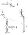
- Fig. 1is a perspective view of a device according to an embodiment of the present invention
- Fig. 2is a top elevation view of a device according to an embodiment of the present invention.
- Fig. 3is a front view of a device according to an embodiment of the present invention.
- Fig. 4is a side elevation view of a device according to an embodiment of the present invention.
- Fig. 5is a perspective view of an example of an attachment mechanism adapted for use in connection with a device according to an embodiment of the present invention
- Fig. 6is a cross-section view of an example of an attachment mechanism adapted for use in connection with a device according to an embodiment of the present invention
- Fig. 7is a perspective view of an attachment mechanism according to an embodiment of the present invention.
- Fig. 8is a cross-section view of an attachment mechanism adapted for use with a device according to an embodiment of the present invention.
- Fig. 9is a cross-section view of an example of an attachment mechanism adapted for use in connection with a device according to an embodiment of the present invention.
- Fig. 10is an example of a control mechanism adapted for use with a device according to an embodiment of the present invention.
- Fig. 11is a cross-section view of a control mechanism adapted for use in connection with a device according to an embodiment of the present invention
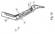
- Fig. 12is a perspective view of a control mechanism adapted for use in connection with a device according to an embodiment of the present invention
- Fig. 13is a connection mechanism adapted for use with a device according to an embodiment of the present invention.
- Fig. 14is a cross-section view of a connection mechanism adapted for use with a device according to an embodiment of the present invention.
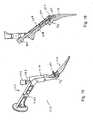
- Fig. 15is a perspective view of a device according to an embodiment of the present invention.
- Fig. 16is a cross-section view of an attachment mechanism adapted for use in connection with a device according to an embodiment of the present invention
- Fig. 17is an exploded view of an alternative attachment mechanism adapted for use in connection with a device according to an embodiment of the present invention.
- Fig. 18is a cross section view of the attachment mechanism shown in Fig. 17 in an open position
- Fig. 19is an elevation view of the attachment mechanism of Fig. 17 in an open position
- Fig. 20is a cross section view of the attachment mechanism of Fig. 17 in a closed position.
- Fig. 21is an elevation view of the attachment mechanism of Fig. 17 in a closed position.
- a surgical devicedesignated generally by reference numeral 10.
- reference numeral 10a surgical device designated generally by reference numeral 10.
- this nomenclatureis used only for convenience and that it is not intended to be limiting with respect to the scope or structure of the invention.
- the deviceis understood to be described only with respect to its orientation and position during an exemplary application to the human body.
- device 10includes handle 12 and shaping instrument 14.
- Shaping instrument 14is of the type typically used in shaping the proximal portion of a femur during hip replacement surgery. Shaping instrument 14 varies in size in accordance with the amount of material to be removed from the femoral canal in order to insert the desired replacement implant. Often, a series of shaping instruments will be used, each successive shaping instrument increasing in size in order to achieve the appropriate shape for the proximal femur.
- shaping instrument 14has a shape that matches that of the femoral implant that is to be inserted into the femoral medullary canal.
- shaping instrument 14has a width such that it defines a medial-lateral plane through the center thereof.
- Shaping instrument 14has two outside surfaces 15 that are substantially parallel to and spaced apart from the medial-lateral plane through the center of shaping instrument 14. These surfaces 15 are formed with a plurality of cutting teeth (not shown) that allow the shaping instrument to remove material from the medullary canal of the proximal femur.
- Shaping instrument 14can be in the form of either a femoral rasp or a femoral broach. The design of these devices is generally known in the art.
- Handle 12is divided into a distal section 16, a transition section 18, and a proximal section 20.
- Handle 12is made of a material that is sufficiently rigid so as to withstand the force needed to properly align and impact shaping instrument 14 into the femoral medullary canal through use in multiple surgical procedures. Suitable materials for handle 12 are stainless steal, titanium or other similar materials.
- proximal section 20may further include a grip 22 or impaction surface 24. Grip 22 allows the user of device 10 to easily hold onto handle 12 during use thereof for purposes of alignment or introduction and removal of shaping instrument 12 with respect to the femoral medullary canal.
- Impaction surface 24provides an area on the proximal end 20 of device 10 upon which the handle can be struck with a hammer, mallet or other such device in order to force shaping instrument 14 into the femoral medullary canal.
- handle 12can be adapted to be used with an automatic impaction device, as it is known in the art.
- Handle portion 12is connected to shaping instrument 14 at distal section 16.
- Transition section 18extends from distal section 16 and links distal section 16 to proximal section 20 such that an appropriate compound offset between proximal section 20 and shaping instrument 14 is achieved.
- transition section 18extends from distal section 16 to proximal section 20 so that proximal section 20 is substantially parallel to shaping instrument 14, being offset therefrom in both the anterior and medial directions.
- Shaping instrument 14has a longitudinal axis oriented generally in the proximal-distal direction.
- proximal section 20has a longitudinal axis oriented in the proximal-distal direction, and defines a medial-lateral plane. The distance of the offset in each direction should be such that shaping instrument 14, can be inserted into the femoral medullary canal using a generally anterior approach, while allowing proximal section 20 of handle 12 to be positioned outside of the wound and while minimizing interference with the soft tissue that surrounds the hip joint of the patient.
- proximal section 20is offset from shaping instrument 14 in the anterior direction by at least 25,4 mm (1 inch), but by no more than 76, 2 mm (3 inches). Similarly, it is preferred that proximal section is offset from the shaping instrument in the medial direction by at least 50,8 mm (2 inches), but by no more than 152,4 mm (6 inches). Most preferably proximal section is offset from shaping instrument by about 50,8 mm (2 inches) in the anterior direction and by about 101,6 mm (4 inches) in the medial direction.
- Transition section 18has a longitudinal axis that is angled relative to the longitudinal axis of shaping instrument 14 in both the medial direction and the anterior direction. Similarly, the longitudinal axis of transition portion 18 is angled relative to the longitudinal axis of proximal section 20 in a posterior direction and a lateral direction. This necessitates the incorporation of a series of bends into device 10. As shown in Fig. 1 , medial bend 26 is incorporated into shaping instrument 14. It is also possible to incorporate medial bend 26 in distal section 16 of handle 12. Medial bend 26 is preferably between 30 and 60 degrees, but is most preferably about 45 degrees. Further locations of medial bend 26 would be apparent to those having reasonable skill in the art having read this disclosure.
- anterior bend 28is incorporated into handle 12 at the point where distal section 16 meets transition section 18.
- Anterior bend 28is preferably between 15 and 45 degrees, but is most preferably about 30 degrees.
- Posterior bend 30 and lateral bend 32are generally positioned at or near the point where transition section 18 meets proximal section 20. Further, posterior bend 30 and lateral bend 32 can be located at approximately the same point in handle 12 forming a compound angle.
- posterior bend 30is of an angle approximately equal to that of anterior bend 28, and lateral bend 32 is about equal to the angle of medial bend 26, such that the longitudinal axes of proximal section 20 and shaping instrument 14 are approximately parallel.
- shaping instrument 14 and handle 12can be integrally formed together, it is preferred that shaping instrument 14 is removably attached to handle 12.
- This arrangementallows different forms of shaping instrument 14, including those of different sizes, to be used with a single handle 12.
- One form of an attachment mechanism 34is shown in Fig. 4 , wherein bore 36 is formed in the attachment surface 37 of distal end 16.
- Trunion 46attached to proximal end 44 of shaping instrument 14, fits within hole 36 and has notch 48 formed therein.
- Threaded hole 35is formed in distal section 16 such that it can engage set screw 41 and such that it forms an intersection 39.
- Set screwis sized and positioned such that it can be turned within threaded hole 35, advancing the end of set screw through intersection 39 and into engagement with notch 48.
- trunion 46is secured within bore 36, thereby affixing shaping instrument 14 to handle 12.
- FIG. 5 and 6An alternative form of attachment mechanism 34 used for fastening shaping instrument 14 to handle 12 is shown in Figs. 5 and 6 .
- This type of mechanism 34is included in distal section 16 of handle 12, and includes first bore 36 in distal section 16 of handle 12 extending from attachment surface 37 of handle 12 in a direction orthogonal thereto.
- Distal section 16further includes a second bore 38 running from the posterior surface of distal section 16 to the anterior surface thereof in a direction orthogonal thereto.
- Second bore 38is positioned within distal section 16 to form an intersection 39 with first bore 36.
- Cam 40is inserted into second bore 38 and has an undercut 42 formed therein.
- the proximal end of rasp 44includes a trunion 46 having a notch 48 formed therein.
- Cam 40is rotatable within second hole 38 such that it is positionable either in an open position or a closed position.
- the open positionis such that undercut 42 of cam 40 is positioned such that cam 40 does not extend through intersection 39 into first bore 46.
- the closed positionis such that undercut 42 is turned away from intersection 39, such that cam 40 extends through the intersection 39 and into first hole 36.
- trunion 46When cam 40 is in the open position, trunion 46 may freely pass into and out of first bore 36.
- handle 12 and shaping instrument 14are assembled together, trunion 46 is inserted into first bore 36 and cam 40 is rotated into the closed position. In the closed position, a portion of cam 40 extends into first bore 36 and engages notch 48 of trunion 46, such that trunion 46 is secured within second bore 36. This results in shaping instrument 14 being secured to handle 12.
- attachment surface 37 of handle 12can include a projection 44 that mates with an opening in the proximal end of the shaping instrument 14. This arrangement prevents rotational movement of shaping instrument 14 with respect to handle 12.
- Attachment mechanism 134includes slot 136 formed in distal section 16 of handle 12 that mates with trunion 46 formed on the proximal portion 44 of shaping instrument 14.
- Distal portion 16 of handle 12further includes a first bore 138 formed between and orthogonal to the anterior and posterior surfaces of distal section 16.
- First bore 138is positioned such that it forms intersection 139 with the medial side of slot 136.
- Cam 140having undercut 142, is positioned in second bore 138 such that it is rotatable between an open position and a closed position. In the open position, undercut 142 of cam 140 is oriented such that cam 140 does not extend through intersection 139 or into slot 136.
- Second bore 150is formed parallel to first bore 138 such that it forms an intersection with the lateral end of slot 136. Second bore 150 has a fixed post 152 secured therein that extends into a portion of slot 136.
- trunion 146allows cam 140 to freely pass in and out of slot 136.
- slot 136should have a length sufficient to allow trunion to clear post 152.
- cam 140When cam 140 is rotated into the closed position, cam 140 pushes trunion 146 toward the medial end of slot 136 such that notch 148 formed in trunion 146 mates with post 152, thereby securing trunion 146 within slot 136, and thus, securing shaping instrument 14 to distal section 16.
- Handle 12has a generally hollow structure defining cavity 153 therein. Within cavity 153 there is included slide member 155 that is slideable in the proximal-distal direction. Plate 154 is affixed to the outside surface of the handle 12 on the lateral section thereof in order to secure slide member within cavity 153.
- the proximal end of spring 156is attached to the proximal end of handle 12, and the distal end of spring 156 is attached to slide member 155 such that it urges slide member 155 toward the proximal end of the handle 12.
- Distal end of slide member 155includes a fork 158, which is attached using pin 160 to slot 162 formed in lever 164 that is attached to cam 140 extending from bore 38 to the outside of distal section 16. In this mechanism, when slide 155 is in its natural position, toward the proximal end of handle 12, cam 140 is forced into the closed position.
- pin 157 secured within fork 158pushes forward on lever 64 causing cam 40 to rotate into its open position.
- connection mechanismDue to positioning of the elements of connection mechanism within distal section 16 of handle 12, it may be necessary to provide a slide member 155 that urges cam 140 into the open position by sliding in the proximal direction. If this is necessary, spring 156 will be such that it urges slide member 155 in the distal direction.
- FIG. 12An alternative control mechanism is shown in Fig. 12 , in which cam 40 is affixed to an elongated lever 66 that extends along transition portion 18 of handle 12 generally in the proximal direction. To selectively control the rotation of cam as between the open and closed positions the user rotates lever 68 in the appropriate direction.
- FIGs. 13 and 14there is shown an alternative attachment mechanism 234 for removably affixing shaping instrument 14 to handle 12.
- This attachment mechanism 234includes a slot 236 formed in distal section 16 of handle 12 that is oriented orthogonally with respect to the attachment surface 37 of handle 12. Slot 236 is adapted to engage trunion 246 which is affixed to proximal section 44 of rasp 14.
- Distal section 16 of handle 12includes bore 150 that has a fixed post 252 secured therein that is adapted to engage notch 248 formed in trunion 246.
- Cavity 270is formed in transition section 18 and distal section 16 of handle 12 and two corresponding sets of slots 274 are formed through the outside wall of transition section 18 to provide access to cavity 270.
- Slots 274are preferably generally oriented at approximately a forty-five degree angle with respect to the longitudinal axis of transition portion 18. This results in slots 274 being oriented approximately in the anterior-posterior direction. Slots 274 and are adapted to engage pins 276, which are affixed to arm 272 disposed in cavity 270, such that pins 276 lie on a anterior-posterior plane. Pins 276 are affixed to and provide support for arm 272 which has hook section 280 formed thereon. Hook section 280 is slideably engaged with wedge 278 which is slideably mounted in cavity 270 such that it can be slid into and out from intersection 239 between cavity 270 and the proximal end of slot 236.
- trunion 246is inserted into slot 236 at the end nearest wedge 278 such that proximal end 44 of rasp 14 contacts attachment surface 37 of handle 12. Pins are then slid in the posterior direction, forcing arm 272 to move within cavity in the same direction such that it exerts a force on wedge 278.
- the slideable engagement between wedge and downwardly-extending portion of armallows wedge to move within slots toward distal end of handle, thereby pushing trunion 246 toward and into engagement with post 252 such that trunion 246 is secured within slot 236.
- Attachment mechanism 234is secured in the closed position by the friction generated between all of the moving parts of this arrangement, in particular between pins 276 and slots 274 and between hook section 280 and wedge 278.
- attachment mechanism 434includes actuator 436, which is rotatably affixed within a cavity 450 formed within transition portion 18 of handle 12.
- the rotatable fixation of actuator 436 to handle 12is preferably achieved using pin 438, which passes through properly aligned holes 440, 442 formed respectively in actuator 436 and handle 12.
- Actuatoris affixed to arm 444, which is preferably in the form of a leaf spring, preferably using pin 446.
- Arm 444extends through cavity 450 and into distal portion 16 of handle 12.
- cavity 450also partially extends into distal portion 16.
- Wedge 448is slideably affixed in the portion of cavity 450 that extends into distal portion 16 such that the distal end 460 of arm 444 contacts the proximal surface of wedge 448.
- Actuator 436 and arm 444are structured such that the rotation of actuator 436 causes arm 444 to slide within cavity in a direction substantially parallel to the longitudinal axis of transition portion 18. The sliding of arm 444 causes arm 444 to push wedge 448.
- distal end 460 of arm 444is designed to slide along the proximal surface of wedge 448 during the sliding motion of the parts to accommodate the difference in direction of the movement. Further, distal end 460 is preferably shaped such that it will not interfere with the inside of cavity 450 as arm is slid partially into distal portion 16.
- the distal surface of wedgeis arranged to contact pin 462, which in slideably engaged within hole 464 formed in distal portion 16 so as to open to cavity 450.
- Pin 462includes an angled surface that serves to transfer the motion of wedge 448, which is in a direction perpendicular to the longitudinal axis of hole 464, into motion of pin 462 in a direction parallel to the longitudinal axis of hole 464.
- arm 444is preferably in the form of a leaf spring and is shaped so as to have a curved section 466 at the proximal end thereof.
- This arrangementallows for compression of arm 444 when the mechanism is in the "closed" position, i.e. when the actuator is turned such that arm 444 exerts a force on wedge, which in turn exerts a force onto pin that holds pin 462 in a position such that pin 462 engages notch 48 formed in post 46 of cutting instrument 14.
- the compression of arm 444 in when mechanism 434 is in the closed positioncan compensate for any wear that may occur with respect to the parts included in mechanism 434 due to repeated use because the compression can be made such that it is greater than any wear that is likely to occur.
- the compression of arm 444can provide a constant force between pin 462 and notch 48, resulting in a more secure attachment of cutting instrument 14 to handle 12.
- the compression of leaf springoccurs primarily in curved portion 466 such that curved portion 466 is curved to a greater extent by the compression of arm 444.
- the arrangement of actuator 436 with respect to arm 444is such that the maximum amount of compression for arm 444 occurs before actuator is rotated fully into the closed position. This arrangement serves to provide a force to actuator 436 that urges actuator 436 to remain in the closed position once placed as such.
- a portion of actuator 436extends along a portion of proximal section 20 of handle 12. As shown in Fig. 17 , this requires a series of bends to be incorporated into actuator 436 that substantially match posterior 30 and lateral 32 bends that are formed in handle 12. Further, a portion of cavity 450 may be formed to extend into proximal section 20 in which actuator 436 may extend when actuator 436 is in the closed position. Further still, actuator 436 may include a flange 437 to aid a user in the manipulation thereof.
- FIG. 15-16an alternative embodiment of device 310 is shown in which device 310 is adapted to attach to joint implant 314.
- joint implant 314is shown as a femoral hip stem implant, it is not limited as such.
- Device 10 of the present inventioncould be used in connection with similar procedures conducted on any joint of the body that can be replaced, including the shoulder, knee or wrist.
- Implant 314 shownis of the type generally used in hip replacement surgery and includes a stem section 315 and a post section 317 that is adapted to engage a ball portion (not shown) of the artificial joint typical of such an arrangement.
- Implant 314has a threaded hole 380 formed therein that is adapted to mate with a rotating threaded post 382 that is affixed to distal section 316 of handle 312.
- Distal section 316has further affixed thereon a support 384 that is adapted to engage post 317 affixed to the proximal end of implant 314.
- threaded hole 380is aligned with post 382 and then post 382 is turned to engage the threads between hole 380 and post 382 which draws implant 314 into contact with distal portion 316 of handle 312.
- Support 384is used to restrict the rotational movement of implant 314 with respect to the handle 312 and to help maintain an appropriate position for implant 314 with respect to handle 312.
- the rotational movement of post 382is controlled by knob 386 which extends from transition section 318 of handle 312. Knob 386 is attached to rod 388 which extends through transition section 318 toward distal section 320. Rod 388 is attached to post 382 using universal joint 390. Universal joint 390 transfers rotational motion about a longitudinal axis of rod 388 into rotational motion about a longitudinal axis of post 382 where the longitudinal axes of the respective elements are oblique relative to each other. The use of such a universal joint 390 is known in the art.
- a deviceis used by selecting an appropriate femoral implant 314 and attaching that femoral implant 314 to handle 310. Then handle 312 is used to insert femoral implant 314 through an incision created during surgery and into the proximal end of the femur having been appropriately prepared to receive implant 314. Implant 314 is then aligned using handle 312 which can be aided by including a radio frequency identification (RFID) device (not shown) either in distal section 316 the handle or in implant 314.
- RFIDradio frequency identification
- knob 386is rotated so as to detach implant 314 from handle 312. Implant 314 is then checked for proper reduction. If necessary, handle 312 is reattached to implant 314 which can be repositioned using handle 312. Once proper reduction is achieved, handle 312 is removed from the incision and the surgery is completed.
Landscapes
- Health & Medical Sciences (AREA)
- Life Sciences & Earth Sciences (AREA)
- Surgery (AREA)
- Orthopedic Medicine & Surgery (AREA)
- Veterinary Medicine (AREA)
- General Health & Medical Sciences (AREA)
- Oral & Maxillofacial Surgery (AREA)
- Engineering & Computer Science (AREA)
- Biomedical Technology (AREA)
- Heart & Thoracic Surgery (AREA)
- Public Health (AREA)
- Animal Behavior & Ethology (AREA)
- Molecular Biology (AREA)
- Nuclear Medicine, Radiotherapy & Molecular Imaging (AREA)
- Medical Informatics (AREA)
- Dentistry (AREA)
- Transplantation (AREA)
- Physical Education & Sports Medicine (AREA)
- Cardiology (AREA)
- Vascular Medicine (AREA)
- Prostheses (AREA)
- Surgical Instruments (AREA)
Description
- A total or partial hip replacement procedure is sometimes necessary to repair diseased or damaged parts of the hip joint, and in particular, the femoral head or the acetabular cup of the hip joint. During replacement of the femoral head, the diseased or damaged head is removed and the remaining portion of the femur is shaped to receive the stem of an implant which extends into the medullary canal of the bone. A prosthetic, spherical or ball-shaped head is attached to the top of the stem and replicates the anatomy of the removed femoral head, fitting into either the remaining acetabular cup or an artificial replacement therefore.
- Shaping of the femoral canal is accomplished using various shaping instruments in the form of femoral rasps or broaches. Generally, such rasps or broaches are designed to match the shape of the stem to be used in the replacement implant so that the femur can be shaped to securely receive the implant. Shaping instruments are inserted into the femoral canal using a handle adapted to affix to the end of the shaping instrument. Many handles have been developed that attach to the proximal portion of shaping instruments for introduction and removal of the shaping instrument from the femur of the patient. However, these handles are designed for use in hip replacement procedures that require either a large incision or a posterior approach in order to gain access to the femur, both of which cause severe trauma to the area surrounding the hip joint increasing the patient's pain and recovery time, and can result in increased risk to the patient.
- In an effort to provide a safer, less-traumatic surgical procedure for replacement of the femoral head, it has been determined that an anterior approach to the proximal femur causes less trauma to the surrounding tissue. An anterior approach is already necessary to gain access to the acetabulum for replacement thereof; thus, the ability to take an anterior approach to the femur eliminates the need for a second incision, or a single, large incision. Additionally, an anterior approach requires less muscle dissection compared to a posterior approach. Traditional instrument handles, such as straight or single-plane angled handles, are not conducive to use in hip replacement surgery using an anterior approach because this procedure typically does not allow for straightline access to the femoral canal, especially when using minimally-invasive surgery (MIS) techniques such as decreased incision size. In particular, problems can arise from the use of traditional handles with respect to alignment of the shaping instrument in the femoral canal, which can cause fracture or misalignment of the femoral implant. Furthermore, problems can arise related to tissue damage from extreme pressure that must be applied to the handle while "fighting" against the tissue for alignment of the shaping instrument within the femoral canal.
- Previous attempts at developing an instrument handle for use in minimally invasive surgery have attempted to adapt an instrument handle for use with an incision that does not directly align with the femoral medullary canal. This has resulted in a handle having a "dual offset" design in which the handle incorporates a series of three perpendicular bends to offset the shaping instrument from the proximal section of the handle in both the posterior and lateral directions. This configuration results in a section of the handle that is oriented in the proximal-distal direction, followed by a section that is oriented in the medial-lateral direction, followed next by a section that extends in the anterior-posterior direction, from which the shaping instrument extends in the proximal-distal direction. As used herein when referring to bones or other parts of the body, the term "proximal" means close to the heart and the term "distal" means more distant from the heart. The term "inferior" means toward the feet and the term "superior" means toward the head. The term "anterior" means toward the front part or the face and the term "posterior" means toward the back of the body. The term "medial" means toward the midline of the body and the term "lateral" means away from the midline of the body.
- This type of handle configuration is capable of reaching the femoral medullary canal through an MIS or anterior approach. However, because the handle has two sections that are orthogonal to the direction of movement of the handle, the handle still interferes with the tissue surrounding the femoral medullary canal, resulting in damage thereto. Furthermore, the severity of the bends used in the handle results in a significant loss of linear impaction force from the proximal end of the handle, where the force is applied, to the instrument, where the force acts. This loss in force is due to the tendency of the perpendicular sections to create torque within the handle in both the lateral and anterior directions. While shaping the femoral medullary canal, it is necessary to minimize torque within the shaping handle because such torque is ultimately applied to the bone, which can cause breakage of the bone or misalignment of the implant. At the very least, the loss of the linear force applied to the handle makes it more difficult to shape the medullary canal for acceptance of the implant because the instrument tends to pitch or yaw within the medullary canal.
- Therefore, it is desirous to provide a handle for a shaping instrument that allows for the shaping instrument to be introduced through a small incision, preferably on the anterior side of the patient. The handle should allow for proper alignment of the shaping instrument, and adequate linear force transmission, while minimizing damage to surrounding tissue.
- During hip replacement surgery, it is often necessary to detach the shaping instrument from its handle. This allows a trial ball-shaped head to be attached to the proximal section of the shaping instrument in a well-known manner for trial reduction of the hip joint. Several variations of such locking mechanisms have been previously developed, but these locking mechanisms are only designed to work with straight or single-plane handles. Therefore, it is also desirous to provide a locking mechanism to attach a shaping instrument to a compound offset handle such that the handle can be easily detached and the handle can be removed from the incision. It is also desirous that this locking mechanism be controlled from the proximal portion of the handle which is located outside of the incision. This prevents the operator from having to reach into the wound to release the handle from or to reattach the handle to the shaping instrument.
- Similar advancements are also desired for insertion of the stem portion of an implant into the prepared femoral canal. Preferably, such a device can be used in connection with a minimally invasive or anterior approach to the femoral canal. It is equally important to have accurate control over placement of the implant and adequate force transmission during impaction of the implant as it is with respect to the use of a shaping instrument.
- The features of the preamble of
claim 1 are known from the documentUS-A-3955568 . - It is therefore, necessary to provide a handle designed for use with a shaping instrument or a femoral implant that can be used in minimally invasive surgery or in surgeries that use an anterior approach to the femoral canal. It is also important for such a device to allow for accurate placement of the instrument or of the femoral implant and accurate and adequate force transmission from the impaction surface to the instrument or stem.
- The present invention relates to a device in accordance with the features of
claim 1. - The implement used in connection with the device can be a shaping instrument used in preparing a joint for receiving an implant. The shaping instrument can be used in connection with any joint of the human body, particularly the hip, shoulder, knee or wrist. Most preferably, the shaping instrument includes a femoral rasp or broach used in preparing the proximal femur of the hip joint. Further embodiments of the invention contemplate a device to be used with a joint implant of a portion thereof, including a knee, shoulder or wrist implant, but an implant for replacement of the femoral portion of the hip is preferred.
- A further embodiment of the present invention relates to a device for use on a patient during surgery. The device includes a shaping instrument having a proximal portion, an anterior surface, and a posterior surface, each surface being spaced apart from a medial-lateral plane through the shaping instrument, and a handle having a distal portion, a transition portion, and a proximal portion. The proximal portion of the shaping instrument is affixed to the distal portion of the handle, and the transition portion of the handle is angled toward an anterior direction and a medial direction with respect to the shaping instrument. The proximal portion of the handle is connected to the transition portion and extends in a proximal direction with a medial-lateral plane therethrough substantially parallel to the medial-lateral plane through the shaping instrument. The shaping instrument can be either permanently affixed, or integrally formed, with the handle. Preferably, the shaping instrument is removably attached to the handle.
- A method for preparing a proximal femoral canal of a patient during hip replacement surgery is subsequently described. In such a method a device according to one embodiment of the present invention is provided. The device is then inserted into the hip joint through a surgical incision and shaping the proximal femur is shaped with the device. The method further includes removing the instrument from the hip joint.
- A method for performing surgery includes providing a device according to a preferred embodiment of the present invention and engaging the distal portion of the device onto a femoral implant. The femoral implant is inserted into the hip joint through a surgical incision and the device is disengaged from the femoral implant. The device is then removed from the surgical incision.
- The present invention will be better understood on reading the following detailed description of nonlimiting embodiments thereof, and on examining the accompanying drawings, in which:
Fig. 1 is a perspective view of a device according to an embodiment of the present invention;Fig. 2 is a top elevation view of a device according to an embodiment of the present invention;Fig. 3 is a front view of a device according to an embodiment of the present invention;Fig. 4 is a side elevation view of a device according to an embodiment of the present invention;Fig. 5 is a perspective view of an example of an attachment mechanism adapted for use in connection with a device according to an embodiment of the present invention;Fig. 6 is a cross-section view of an example of an attachment mechanism adapted for use in connection with a device according to an embodiment of the present invention;Fig. 7 is a perspective view of an attachment mechanism according to an embodiment of the present invention;Fig. 8 is a cross-section view of an attachment mechanism adapted for use with a device according to an embodiment of the present invention;Fig. 9 is a cross-section view of an example of an attachment mechanism adapted for use in connection with a device according to an embodiment of the present invention;Fig. 10 is an example of a control mechanism adapted for use with a device according to an embodiment of the present invention;Fig. 11 is a cross-section view of a control mechanism adapted for use in connection with a device according to an embodiment of the present invention;Fig. 12 is a perspective view of a control mechanism adapted for use in connection with a device according to an embodiment of the present invention;Fig. 13 is a connection mechanism adapted for use with a device according to an embodiment of the present invention;Fig. 14 is a cross-section view of a connection mechanism adapted for use with a device according to an embodiment of the present invention.Fig. 15 is a perspective view of a device according to an embodiment of the present invention;Fig. 16 is a cross-section view of an attachment mechanism adapted for use in connection with a device according to an embodiment of the present invention;Fig. 17 is an exploded view of an alternative attachment mechanism adapted for use in connection with a device according to an embodiment of the present invention;Fig. 18 is a cross section view of the attachment mechanism shown inFig. 17 in an open position;Fig. 19 is an elevation view of the attachment mechanism ofFig. 17 in an open position;Fig. 20 is a cross section view of the attachment mechanism ofFig. 17 in a closed position; andFig. 21 is an elevation view of the attachment mechanism ofFig. 17 in a closed position.- In describing the preferred embodiments of the subject matter illustrated and to be described with respect to the drawings, specific terminology will be resorted to for the sake of clarity. However, the invention is not intended to be limited to the specific terms so selected, and it is to be understood that each specific term includes all technical equivalents which operate in a similar manner to accomplish a similar purpose.
- Referring to the drawings, wherein like reference numerals represent like elements, there is shown in
Fig. 1 , in accordance with one embodiment of the present invention, a surgical device designated generally byreference numeral 10. In describing preferred embodiments of the device of the present invention, reference will be made to the directional nomenclature used in describing the human body. It is noted that this nomenclature is used only for convenience and that it is not intended to be limiting with respect to the scope or structure of the invention. When referring to specific directions, the device is understood to be described only with respect to its orientation and position during an exemplary application to the human body. - In an embodiment of the present invention,
device 10 includeshandle 12 and shapinginstrument 14. Shapinginstrument 14 is of the type typically used in shaping the proximal portion of a femur during hip replacement surgery. Shapinginstrument 14 varies in size in accordance with the amount of material to be removed from the femoral canal in order to insert the desired replacement implant. Often, a series of shaping instruments will be used, each successive shaping instrument increasing in size in order to achieve the appropriate shape for the proximal femur. - Generally, shaping
instrument 14 has a shape that matches that of the femoral implant that is to be inserted into the femoral medullary canal. Generally, shapinginstrument 14 has a width such that it defines a medial-lateral plane through the center thereof. Shapinginstrument 14 has twooutside surfaces 15 that are substantially parallel to and spaced apart from the medial-lateral plane through the center of shapinginstrument 14. Thesesurfaces 15 are formed with a plurality of cutting teeth (not shown) that allow the shaping instrument to remove material from the medullary canal of the proximal femur. Shapinginstrument 14 can be in the form of either a femoral rasp or a femoral broach. The design of these devices is generally known in the art. Handle 12 is divided into adistal section 16, atransition section 18, and aproximal section 20.Handle 12 is made of a material that is sufficiently rigid so as to withstand the force needed to properly align and impact shapinginstrument 14 into the femoral medullary canal through use in multiple surgical procedures. Suitable materials forhandle 12 are stainless steal, titanium or other similar materials. For ease of use,proximal section 20 may further include agrip 22 orimpaction surface 24.Grip 22 allows the user ofdevice 10 to easily hold ontohandle 12 during use thereof for purposes of alignment or introduction and removal of shapinginstrument 12 with respect to the femoral medullary canal.Impaction surface 24 provides an area on theproximal end 20 ofdevice 10 upon which the handle can be struck with a hammer, mallet or other such device in order to force shapinginstrument 14 into the femoral medullary canal. To further aid in impaction of shapinginstrument 14 into the femoral medullary canal, handle 12 can be adapted to be used with an automatic impaction device, as it is known in the art.Handle portion 12 is connected to shapinginstrument 14 atdistal section 16.Transition section 18 extends fromdistal section 16 and linksdistal section 16 toproximal section 20 such that an appropriate compound offset betweenproximal section 20 and shapinginstrument 14 is achieved.- In general,
transition section 18 extends fromdistal section 16 toproximal section 20 so thatproximal section 20 is substantially parallel to shapinginstrument 14, being offset therefrom in both the anterior and medial directions. Shapinginstrument 14 has a longitudinal axis oriented generally in the proximal-distal direction. Similarly,proximal section 20 has a longitudinal axis oriented in the proximal-distal direction, and defines a medial-lateral plane. The distance of the offset in each direction should be such that shapinginstrument 14, can be inserted into the femoral medullary canal using a generally anterior approach, while allowingproximal section 20 ofhandle 12 to be positioned outside of the wound and while minimizing interference with the soft tissue that surrounds the hip joint of the patient. Preferably,proximal section 20 is offset from shapinginstrument 14 in the anterior direction by at least 25,4 mm (1 inch), but by no more than 76, 2 mm (3 inches). Similarly, it is preferred that proximal section is offset from the shaping instrument in the medial direction by at least 50,8 mm (2 inches), but by no more than 152,4 mm (6 inches). Most preferably proximal section is offset from shaping instrument by about 50,8 mm (2 inches) in the anterior direction and by about 101,6 mm (4 inches) in the medial direction. Transition section 18 has a longitudinal axis that is angled relative to the longitudinal axis of shapinginstrument 14 in both the medial direction and the anterior direction. Similarly, the longitudinal axis oftransition portion 18 is angled relative to the longitudinal axis ofproximal section 20 in a posterior direction and a lateral direction. This necessitates the incorporation of a series of bends intodevice 10. As shown inFig. 1 ,medial bend 26 is incorporated into shapinginstrument 14. It is also possible to incorporatemedial bend 26 indistal section 16 ofhandle 12.Medial bend 26 is preferably between 30 and 60 degrees, but is most preferably about 45 degrees. Further locations ofmedial bend 26 would be apparent to those having reasonable skill in the art having read this disclosure.- As further shown in
Fig. 1 ,anterior bend 28 is incorporated intohandle 12 at the point wheredistal section 16 meetstransition section 18.Anterior bend 28 is preferably between 15 and 45 degrees, but is most preferably about 30 degrees.Posterior bend 30 andlateral bend 32 are generally positioned at or near the point wheretransition section 18 meetsproximal section 20. Further,posterior bend 30 andlateral bend 32 can be located at approximately the same point inhandle 12 forming a compound angle. Preferably,posterior bend 30 is of an angle approximately equal to that ofanterior bend 28, andlateral bend 32 is about equal to the angle ofmedial bend 26, such that the longitudinal axes ofproximal section 20 and shapinginstrument 14 are approximately parallel. - While shaping
instrument 14 and handle 12 can be integrally formed together, it is preferred that shapinginstrument 14 is removably attached to handle 12. This arrangement allows different forms of shapinginstrument 14, including those of different sizes, to be used with asingle handle 12. One form of anattachment mechanism 34 is shown inFig. 4 , wherein bore 36 is formed in the attachment surface 37 ofdistal end 16.Trunion 46, attached to proximal end 44 of shapinginstrument 14, fits withinhole 36 and hasnotch 48 formed therein. Threaded hole 35 is formed indistal section 16 such that it can engage set screw 41 and such that it forms an intersection 39. Set screw is sized and positioned such that it can be turned within threaded hole 35, advancing the end of set screw through intersection 39 and into engagement withnotch 48. As such,trunion 46 is secured withinbore 36, thereby affixing shapinginstrument 14 to handle 12. - An alternative form of
attachment mechanism 34 used for fastening shapinginstrument 14 to handle 12 is shown inFigs. 5 and 6 . This type ofmechanism 34 is included indistal section 16 ofhandle 12, and includes first bore 36 indistal section 16 ofhandle 12 extending from attachment surface 37 ofhandle 12 in a direction orthogonal thereto.Distal section 16 further includes asecond bore 38 running from the posterior surface ofdistal section 16 to the anterior surface thereof in a direction orthogonal thereto. Second bore 38 is positioned withindistal section 16 to form an intersection 39 withfirst bore 36.Cam 40 is inserted intosecond bore 38 and has an undercut 42 formed therein. The proximal end of rasp 44 includes atrunion 46 having anotch 48 formed therein.Cam 40 is rotatable withinsecond hole 38 such that it is positionable either in an open position or a closed position. The open position is such that undercut 42 ofcam 40 is positioned such thatcam 40 does not extend through intersection 39 intofirst bore 46. The closed position is such that undercut 42 is turned away from intersection 39, such thatcam 40 extends through the intersection 39 and intofirst hole 36. - When
cam 40 is in the open position,trunion 46 may freely pass into and out offirst bore 36. When handle 12 and shapinginstrument 14 are assembled together,trunion 46 is inserted intofirst bore 36 andcam 40 is rotated into the closed position. In the closed position, a portion ofcam 40 extends intofirst bore 36 and engages notch 48 oftrunion 46, such thattrunion 46 is secured withinsecond bore 36. This results in shapinginstrument 14 being secured to handle 12. In order to aid in securing shapinginstrument 14 to handle 12, attachment surface 37 ofhandle 12 can include a projection 44 that mates with an opening in the proximal end of the shapinginstrument 14. This arrangement prevents rotational movement of shapinginstrument 14 with respect to handle 12. - Referring now to
Figs. 7-9 , an alternative variation ofattachment mechanism 134 is shown.Attachment mechanism 134 includesslot 136 formed indistal section 16 ofhandle 12 that mates withtrunion 46 formed on the proximal portion 44 of shapinginstrument 14.Distal portion 16 ofhandle 12 further includes a first bore 138 formed between and orthogonal to the anterior and posterior surfaces ofdistal section 16. First bore 138 is positioned such that it forms intersection 139 with the medial side ofslot 136.Cam 140, having undercut 142, is positioned in second bore 138 such that it is rotatable between an open position and a closed position. In the open position, undercut 142 ofcam 140 is oriented such thatcam 140 does not extend through intersection 139 or intoslot 136. The closed position is such that the undercut is turned away from the intersection, and the body of cam extends through the intersection and into a portion ofslot 136.Second bore 150 is formed parallel to first bore 138 such that it forms an intersection with the lateral end ofslot 136.Second bore 150 has a fixed post 152 secured therein that extends into a portion ofslot 136. Whencam 140 is in the open position,trunion 146 allowscam 140 to freely pass in and out ofslot 136. To allowtrunion 146 to be freely moveable in and out ofslot 136 when cam is in the open position, slot 136 should have a length sufficient to allow trunion to clear post 152. Whencam 140 is rotated into the closed position,cam 140 pushes trunion 146 toward the medial end ofslot 136 such thatnotch 148 formed intrunion 146 mates with post 152, thereby securingtrunion 146 withinslot 136, and thus, securing shapinginstrument 14 todistal section 16. - In order for the user of
device 10 to detach and reattach shapinginstrument 14 fromhandle 12 without the need to physically reach into the incision in the patient through which the device is inserted, a control means is provided in conjunction withhandle 12. An example of such control means is shown inFigs. 10 and 11 .Handle 12 has a generally hollowstructure defining cavity 153 therein. Withincavity 153 there is includedslide member 155 that is slideable in the proximal-distal direction.Plate 154 is affixed to the outside surface of thehandle 12 on the lateral section thereof in order to secure slide member withincavity 153. The proximal end ofspring 156 is attached to the proximal end ofhandle 12, and the distal end ofspring 156 is attached to slidemember 155 such that it urgesslide member 155 toward the proximal end of thehandle 12. Distal end ofslide member 155 includes a fork 158, which is attached using pin 160 to slot 162 formed in lever 164 that is attached tocam 140 extending frombore 38 to the outside ofdistal section 16. In this mechanism, whenslide 155 is in its natural position, toward the proximal end ofhandle 12,cam 140 is forced into the closed position. When the user of thedevice 10 slides slidemember 155 toward the distal end ofhandle 12, pin 157 secured within fork 158 pushes forward onlever 64 causingcam 40 to rotate into its open position. - Due to positioning of the elements of connection mechanism within
distal section 16 ofhandle 12, it may be necessary to provide aslide member 155 that urgescam 140 into the open position by sliding in the proximal direction. If this is necessary,spring 156 will be such that it urgesslide member 155 in the distal direction. - An alternative control mechanism is shown in
Fig. 12 , in whichcam 40 is affixed to anelongated lever 66 that extends alongtransition portion 18 ofhandle 12 generally in the proximal direction. To selectively control the rotation of cam as between the open and closed positions the user rotates lever 68 in the appropriate direction. - In
Figs. 13 and 14 there is shown analternative attachment mechanism 234 for removably affixing shapinginstrument 14 to handle 12. Thisattachment mechanism 234 includes a slot 236 formed indistal section 16 ofhandle 12 that is oriented orthogonally with respect to the attachment surface 37 ofhandle 12. Slot 236 is adapted to engagetrunion 246 which is affixed to proximal section 44 ofrasp 14.Distal section 16 ofhandle 12 includes bore 150 that has a fixed post 252 secured therein that is adapted to engagenotch 248 formed intrunion 246.Cavity 270 is formed intransition section 18 anddistal section 16 ofhandle 12 and two corresponding sets ofslots 274 are formed through the outside wall oftransition section 18 to provide access tocavity 270. Slots 274 are preferably generally oriented at approximately a forty-five degree angle with respect to the longitudinal axis oftransition portion 18. This results inslots 274 being oriented approximately in the anterior-posterior direction.Slots 274 and are adapted to engagepins 276, which are affixed to arm 272 disposed incavity 270, such thatpins 276 lie on a anterior-posterior plane.Pins 276 are affixed to and provide support forarm 272 which has hook section 280 formed thereon. Hook section 280 is slideably engaged withwedge 278 which is slideably mounted incavity 270 such that it can be slid into and out from intersection 239 betweencavity 270 and the proximal end of slot 236. In operation,trunion 246 is inserted into slot 236 at the end nearestwedge 278 such that proximal end 44 ofrasp 14 contacts attachment surface 37 ofhandle 12. Pins are then slid in the posterior direction, forcingarm 272 to move within cavity in the same direction such that it exerts a force onwedge 278. The slideable engagement between wedge and downwardly-extending portion of arm allows wedge to move within slots toward distal end of handle, thereby pushingtrunion 246 toward and into engagement with post 252 such thattrunion 246 is secured within slot 236.Attachment mechanism 234 is secured in the closed position by the friction generated between all of the moving parts of this arrangement, in particular betweenpins 276 andslots 274 and between hook section 280 andwedge 278.- A further
alternative attachment mechanism 434 is shown inFigs. 17-21 . In this embodiment, attachment mechanism includesactuator 436, which is rotatably affixed within acavity 450 formed withintransition portion 18 ofhandle 12. The rotatable fixation ofactuator 436 to handle 12 is preferably achieved usingpin 438, which passes through properly alignedholes 440, 442 formed respectively inactuator 436 and handle 12. Actuator is affixed toarm 444, which is preferably in the form of a leaf spring, preferably usingpin 446.Arm 444 extends throughcavity 450 and intodistal portion 16 ofhandle 12. Preferably,cavity 450 also partially extends intodistal portion 16.Wedge 448 is slideably affixed in the portion ofcavity 450 that extends intodistal portion 16 such that thedistal end 460 ofarm 444 contacts the proximal surface ofwedge 448.Actuator 436 andarm 444 are structured such that the rotation ofactuator 436 causesarm 444 to slide within cavity in a direction substantially parallel to the longitudinal axis oftransition portion 18. The sliding ofarm 444 causesarm 444 to pushwedge 448. - As shown in
Figs. 19 and21 , the direction of motion ofwedge 448 within cavity is angled relative to the direction of motion ofarm 444. This is due to the location ofanterior bend 28 betweendistal portion 16 andtransition portion 18.Distal end 460 ofarm 444 is designed to slide along the proximal surface ofwedge 448 during the sliding motion of the parts to accommodate the difference in direction of the movement. Further,distal end 460 is preferably shaped such that it will not interfere with the inside ofcavity 450 as arm is slid partially intodistal portion 16. - The distal surface of wedge is arranged to contact
pin 462, which in slideably engaged withinhole 464 formed indistal portion 16 so as to open tocavity 450.Pin 462 includes an angled surface that serves to transfer the motion ofwedge 448, which is in a direction perpendicular to the longitudinal axis ofhole 464, into motion ofpin 462 in a direction parallel to the longitudinal axis ofhole 464. - As previously stated
arm 444 is preferably in the form of a leaf spring and is shaped so as to have acurved section 466 at the proximal end thereof. This arrangement allows for compression ofarm 444 when the mechanism is in the "closed" position, i.e. when the actuator is turned such thatarm 444 exerts a force on wedge, which in turn exerts a force onto pin that holdspin 462 in a position such thatpin 462 engagesnotch 48 formed inpost 46 of cuttinginstrument 14. The compression ofarm 444 in whenmechanism 434 is in the closed position can compensate for any wear that may occur with respect to the parts included inmechanism 434 due to repeated use because the compression can be made such that it is greater than any wear that is likely to occur. Further, the compression ofarm 444 can provide a constant force betweenpin 462 and notch 48, resulting in a more secure attachment of cuttinginstrument 14 to handle 12. Preferably the compression of leaf spring occurs primarily incurved portion 466 such thatcurved portion 466 is curved to a greater extent by the compression ofarm 444. Further, the arrangement ofactuator 436 with respect toarm 444 is such that the maximum amount of compression forarm 444 occurs before actuator is rotated fully into the closed position. This arrangement serves to provide a force to actuator 436 that urgesactuator 436 to remain in the closed position once placed as such. - Preferably, a portion of
actuator 436 extends along a portion ofproximal section 20 ofhandle 12. As shown inFig. 17 , this requires a series of bends to be incorporated intoactuator 436 that substantially matchposterior 30 and lateral 32 bends that are formed inhandle 12. Further, a portion ofcavity 450 may be formed to extend intoproximal section 20 in which actuator 436 may extend whenactuator 436 is in the closed position. Further still,actuator 436 may include aflange 437 to aid a user in the manipulation thereof. - Referring now to
Figs. 15-16 , an alternative embodiment ofdevice 310 is shown in whichdevice 310 is adapted to attach tojoint implant 314. Althoughjoint implant 314 is shown as a femoral hip stem implant, it is not limited as such.Device 10 of the present invention could be used in connection with similar procedures conducted on any joint of the body that can be replaced, including the shoulder, knee or wrist.Implant 314 shown is of the type generally used in hip replacement surgery and includes a stem section 315 and a post section 317 that is adapted to engage a ball portion (not shown) of the artificial joint typical of such an arrangement. Implant 314 has a threadedhole 380 formed therein that is adapted to mate with a rotating threadedpost 382 that is affixed todistal section 316 ofhandle 312.Distal section 316 has further affixed thereon asupport 384 that is adapted to engage post 317 affixed to the proximal end ofimplant 314. In operation, threadedhole 380 is aligned withpost 382 and then post 382 is turned to engage the threads betweenhole 380 and post 382 which drawsimplant 314 into contact withdistal portion 316 ofhandle 312.Support 384 is used to restrict the rotational movement ofimplant 314 with respect to thehandle 312 and to help maintain an appropriate position forimplant 314 with respect to handle 312.- Preferably, the rotational movement of
post 382 is controlled byknob 386 which extends fromtransition section 318 ofhandle 312.Knob 386 is attached torod 388 which extends throughtransition section 318 towarddistal section 320.Rod 388 is attached to post 382 usinguniversal joint 390. Universal joint 390 transfers rotational motion about a longitudinal axis ofrod 388 into rotational motion about a longitudinal axis ofpost 382 where the longitudinal axes of the respective elements are oblique relative to each other. The use of such auniversal joint 390 is known in the art. - A device according to this particular embodiment of the present invention is used by selecting an appropriate
femoral implant 314 and attaching thatfemoral implant 314 to handle 310. Then handle 312 is used to insertfemoral implant 314 through an incision created during surgery and into the proximal end of the femur having been appropriately prepared to receiveimplant 314.Implant 314 is then aligned usinghandle 312 which can be aided by including a radio frequency identification (RFID) device (not shown) either indistal section 316 the handle or inimplant 314. The use of RFID devices in alignment of implants and shaping instruments is known in the art. Once proper alignment is achieved,knob 386 is rotated so as to detachimplant 314 fromhandle 312.Implant 314 is then checked for proper reduction. If necessary, handle 312 is reattached to implant 314 which can be repositioned usinghandle 312. Once proper reduction is achieved, handle 312 is removed from the incision and the surgery is completed. - Although the invention herein has been described with reference to particular embodiments, it is to be understood that these embodiments are merely illustrative of the principles and applications of the present invention. It is therefore to be understood that numerous modifications may be made to the illustrative embodiments and that other arrangements may be devised without departing from the scope of the present invention as defined by the appended claims.
Claims (29)
- A device for use with an implement in combination with said implement on a patient during surgery comprising:a handle (12; 312) having:a. a proximal portion (20; 320) having a longitudinal axis ;b. a transition portion (18; 318) having a longitudinal axis ;c. a distal portion (16;320) being adapted to attach to said implement (11; 314) having a longitudinal axis, a proximal portion, an anterior surface and a posterior surface, each surface being spaced apart from a medial-lateral plane through the implement (14; 314) ;characterized in that the longitudinal axis of said transition portion (18;318) is angled .in an anterior direction with an anterior (28) bend and a medial direction with a medial (26) bend with respect to the longitudinal axis of the implement (14;314), the longitudinal axis of said transition portion (18; 318) is further angled in a posterior direction with a posterior (30) bend and a lateral direction with a lateral (32) bend with respect to the longitudinal axis of the proximal portion (20;320), said proximal portion (20; 320) of said handle being connected to said transition portion (18;318) and expending in a proximal direction with a medial-lateral plane therethrough that is, when the distal portion (16;316) of the handle is attached to the implement (14; 314), substantially parallel to the medial-lateral plane through the implement (14; 314).
- The device of claim 1 further comprising a grip (22) affixed to said proximal portion (20).
- The device of claim 1 further comprising an impaction face (24) affixed to said proximal portion (20).
- The device of claim 1, wherein, said handle is adapted for use with an automatic impaction device.
- The device of claim 1, wherein, the device further comprising the implement, the implement is a shaping instrument.
- The device of claim 5, wherein the proximal portion of the shaping instrument is affixed to said distal portion.
- The device of claim 5, wherein the proximal portion of the shaping instrument is removably affixed to said distal portion.
- The device of claim 5, wherein the shaping instrument is a rasp.
- The device of claim 5, wherein the shaping instrument is a broach.
- The device of claim 6 or 7, wherein said proximal portion of said shaping instrument is removably affixed to said distal portion of said handle.
- The device of claim 10 further comprising:a. a trunion affixed to said proximal portion of said shaping instrument and having a notch formed therein;b. a first bore located in said distal end of said handle and adapted for receiving said trunion;c. a second bore located in said distal end of said handle that is substantially normal to said first bore; andd. a cam rotatably disposed within said second bore and having an undercut formed therein;
wherein said cam is rotatable between a first position and a second position, said first position being such that said undercut allows said trunion to be freely engaged and disengaged from within said first bore, and said second position being such
that said cam engages said notch of said trunion, thereby securing said trunion within said first bore. - The device of claim 11 further comprising a means for selectively securing said cam in each of said first position and said second position.
- The device of claim 12 further comprising a means for controlling the movement of said cam.
- The device of claim 13 further comprising an arm affixed to said cam and expending at least partially in a proximal direction.
- The device of claim 10 further comprising:a. a trunion affixed to said proximal portion of said shaping instrument and having a notch formed therein;b. a slot having a first rounded end and a second rounded end, said slot being located in said distal end of said handle and being adapted for receiving said trunion such that said trunion is slideable between said first rounded end and said second rounded end;c. a fixed post positioned at least partially within said second rounded end of said slot, said fixed post being adapted to engage said notch formed in said trunion;d. a bore located within said distal end of said handle such that an intersection is formed between said bore and said first rounded end of said slot; ande. a cam rotatably disposed within said bore; wherein said cam is rotatable between a first position and a second position, said first position being such that said trunion can be freely engaged and disengaged from within said slot, and said second position being such that said cam forces said trunion toward said second end of said slot such that said notch engages said fixed post, thereby securing said trunion within said slot.
- The device of claim 15 furthers comprising means for selectively securing said cam in each of said first position and second position.
- The device of claim 15 further comprising a means for controlling the movement of said cam.
- The device of claim 10 further comprising:a. a a trunion affixed to said proximal portion of said sharing instrument and having a notch formed therein;b. a slot having a first rounded end and a second rounded end, said slot being located in said distal end of said handle and being adapted for receiving said trunion such that said trunion is slideable between said first rounded end and said second rounded end;c. a fixed post positioned at least partially within said second rounder end of staid slot, said fixed post being adapted to engage said notch formed in said trunion;d. a cavity formed within said distal portion of said handle and extending into said transition portion of said dandle;e. a wedge disposed within said cavity, said wedge being capable of slideably movement within said cavity between a first position and a second position, said first position being such that said trunion can be freely engaged and disengaged from within said slot, and said second position being such that said wedge forces said trunion toward said second end of said slot such that said notch engages said fixed post, thereby securing said trunion within said slot ;f. means for controlling the slidable movement of said wedge.
- The device of claim 18 further comprising:a. a hole located in said proximal portion of said instrument; andb. a post affixed to said distal portion of said handle;
wherein said hole and said post are positioned such that, when said trunion is secured within said slot, said post fits within said bolt, thereby preventing said shaping instrument from rotating relative to said handle. - The device of claim 1, wherein, the device further comprising the implement, the implement is a joint implant.
- The device of claim 20, wherein the implement is a femoral implant.
- The device of claim 21, wherein said distal portion is adapted to be removably affixed to the femoral implant.
- The device of claim 22 further including a post affixed to said distale portion, said post being at least partially threaded so as to engage with a threaded hole defined is the proximal portion of the femoral implant.
- The device of claim 23, wherein said post is rotatably affixed to said distal portion.
- The device of claim 24 further including means for controlling the rotation of said post.
- The device of claim 25, wherein said means for controlling extends through said transition portion.
- The device of claim 26, wherein said means for controlling includes a universal joint.
- The device of claim 23, wherein said handle further includes a support adapted to engage a trunion extending from the proximal portion of the femoral implant.
- The device of claim 1, wherein the posterior bend (30) and the lateral, bend (32) are located at approximately the same point in handle (12) , thereby forming a compound angle
Priority Applications (1)
| Application Number | Priority Date | Filing Date | Title |
|---|---|---|---|
| EP10163915.1AEP2236107B1 (en) | 2006-03-06 | 2007-03-06 | Compound offset handle |
Applications Claiming Priority (1)
| Application Number | Priority Date | Filing Date | Title |
|---|---|---|---|
| US11/368,761US7935125B2 (en) | 2006-03-06 | 2006-03-06 | Compound offset handle |
Related Child Applications (2)
| Application Number | Title | Priority Date | Filing Date |
|---|---|---|---|
| EP10163915.1ADivisionEP2236107B1 (en) | 2006-03-06 | 2007-03-06 | Compound offset handle |
| EP10163915.1Division-Into | 2010-05-26 |
Publications (3)
| Publication Number | Publication Date |
|---|---|
| EP1832248A2 EP1832248A2 (en) | 2007-09-12 |
| EP1832248A3 EP1832248A3 (en) | 2007-11-07 |
| EP1832248B1true EP1832248B1 (en) | 2012-11-28 |
Family
ID=38124054
Family Applications (2)
| Application Number | Title | Priority Date | Filing Date |
|---|---|---|---|
| EP10163915.1AActiveEP2236107B1 (en) | 2006-03-06 | 2007-03-06 | Compound offset handle |
| EP07103548AActiveEP1832248B1 (en) | 2006-03-06 | 2007-03-06 | Compound offset handle |
Family Applications Before (1)
| Application Number | Title | Priority Date | Filing Date |
|---|---|---|---|
| EP10163915.1AActiveEP2236107B1 (en) | 2006-03-06 | 2007-03-06 | Compound offset handle |
Country Status (4)
| Country | Link |
|---|---|
| US (4) | US7935125B2 (en) |
| EP (2) | EP2236107B1 (en) |
| AU (1) | AU2007200979B2 (en) |
| CA (1) | CA2581517C (en) |
Families Citing this family (50)
| Publication number | Priority date | Publication date | Assignee | Title |
|---|---|---|---|---|
| US8657824B2 (en) | 2003-11-18 | 2014-02-25 | Smith & Nephew, Inc. | Universal double offset surgical instrument |
| DE602004023422D1 (en) | 2003-11-18 | 2009-11-12 | Smith & Nephew Inc | OPERATIVE TECHNIQUE AND INSTRUMENTS FOR MINIMAL INCISION HIP ARTHOPLASTY SURGERY |
| US7935125B2 (en) | 2006-03-06 | 2011-05-03 | Howmedica Osteonics Corp. | Compound offset handle |
| US8425526B2 (en) | 2006-10-17 | 2013-04-23 | Smith & Nephew, Inc. | Adjustable impactor |
| FR2924771B1 (en)* | 2007-12-05 | 2012-12-28 | Marnaise Applic Orthopediques Smao Soc | CLOSING SYSTEM WITH LATCH BETWEEN TWO ELEMENTS |
| FR2926208B1 (en)* | 2008-01-08 | 2010-12-31 | X Nov | ANCILLARY, IN PARTICULAR FOR THE INSTALLATION OF A HIP PROSTHESIS. |
| EP2240084B1 (en) | 2008-02-05 | 2016-05-11 | Texas Scottish Rite Hospital For Children | External fixator ring |
| EP2240085A4 (en) | 2008-02-08 | 2014-01-01 | Texas Scottish Rite Hospital | STATE OF EXTERNAL FIXATION |
| EP2249721B1 (en) | 2008-02-12 | 2017-07-05 | Texas Scottish Rite Hospital For Children | Fast adjust external fixation connection rod |
| EP2252222B1 (en)* | 2008-02-18 | 2014-03-26 | Texas Scottish Rite Hospital For Children | Tool for external fixation strut adjustment |
| US8052755B2 (en) | 2008-05-09 | 2011-11-08 | Remi Sciences, Inc. | Ulnar head prosthesis system |
| US7875082B2 (en) | 2008-05-09 | 2011-01-25 | Remi Sciences, Inc. | Ulnar head prosthesis system |
| DE102009024654B4 (en)* | 2009-06-12 | 2021-01-28 | Peter Brehm Holding Gmbh & Co. Kg | Interchangeable handle for a functional part and surgical device |
| FR2947169B1 (en)* | 2009-06-30 | 2012-04-27 | Xnov | HALF RING HOLDER WITH MOBILE JAW |
| US8966867B2 (en)* | 2009-12-29 | 2015-03-03 | Howmedica Osteonics Corp. | Implant package |
| WO2012023876A1 (en) | 2010-08-20 | 2012-02-23 | Amei Technologies, Inc. | Method and system for roentgenography-based modeling |
| US9119644B2 (en)* | 2010-08-21 | 2015-09-01 | New York Society For The Ruptured And Crippled Maintaining The Hospital For Special Surgery | Instruments for use in femoroacetabular impingement procedures |
| US9456810B2 (en)* | 2012-01-13 | 2016-10-04 | Smith & Nephew, Inc. | Surgical instrument handle assembly |
| US20130261626A1 (en)* | 2012-03-29 | 2013-10-03 | Jason M. Chavarria | Orthopaedic surgical instrument for removing an implanted humeral stem component and method of using the same |
| US9610084B2 (en) | 2012-09-12 | 2017-04-04 | Peter Michael Sutherland Walker | Method and apparatus for hip replacements |
| US9084685B2 (en)* | 2012-09-28 | 2015-07-21 | DePuy Synthes Products, Inc. | Femoral prosthesis with insertion/extraction feature |
| US10667798B2 (en) | 2012-10-29 | 2020-06-02 | Zimmer, Inc. | Surgical tool handle assemblies and related methods |
| US8574232B1 (en) | 2012-11-13 | 2013-11-05 | Texas Scottish Hospital for Children | External fixation connection rod for rapid and gradual adjustment |
| US9554810B2 (en) | 2013-03-15 | 2017-01-31 | Depuy Ireland Unlimited Company | Femoral system handle surgical instrument and method of assembling same |
| FR3004331B1 (en)* | 2013-04-11 | 2015-04-17 | Maurice Marle Ets | REMOVABLE HAND WITH A DISMANTLING ASSEMBLY DEVICE |
| US10064629B2 (en)* | 2014-07-30 | 2018-09-04 | Zimmer, Inc. | Bone perforator |
| US9987043B2 (en) | 2014-10-24 | 2018-06-05 | Stryker European Holdings I, Llc | Methods and systems for adjusting an external fixation frame |
| US10085838B2 (en)* | 2015-01-15 | 2018-10-02 | Depuy Ireland Unlimited Company | Assembly tool |
| USD780548S1 (en) | 2015-07-22 | 2017-03-07 | Ac (Macao Commercial Offshore) Limited | Power tool |
| USD806493S1 (en) | 2015-07-22 | 2018-01-02 | Tti (Macao Commercial Offshore) Limited | Tool adapter |
| US10368913B2 (en) | 2015-08-10 | 2019-08-06 | Stryker European Holdings I, Llc | Adjustment instrument with tactile feedback |
| US11246624B2 (en)* | 2015-11-06 | 2022-02-15 | Joint Development, Llc | Broach holder tool with reduced rasp moment |
| US11116509B2 (en) | 2017-11-10 | 2021-09-14 | Avantec Vascular Corporation | System and method for delivering an embolic device |
| WO2020070244A1 (en) | 2018-10-04 | 2020-04-09 | Depuy Ireland Unlimited Company | Prosthesis extraction system |
| US11660201B2 (en)* | 2018-10-25 | 2023-05-30 | Wright Medical Technology, Inc. | Systems, apparatuses, and methods for correcting a bone defect |
| USD929589S1 (en)* | 2019-01-18 | 2021-08-31 | Shukla Medical | Surgical striking apparatus |
| GB201901590D0 (en)* | 2019-02-05 | 2019-03-27 | Smith & Nephew Orthopaedics Ag | Robust impactor |
| JP7270063B2 (en)* | 2019-05-14 | 2023-05-09 | ローサイ・オーソペディックス・リミテッド | A set of tools for introducing implants |
| US11622869B2 (en)* | 2019-07-29 | 2023-04-11 | Tri-Sphere Holdings | Femoral component extractor |
| EP4527357A3 (en)* | 2019-10-01 | 2025-06-04 | Howmedica Osteonics Corporation | Shoulder prosthesis components and assemblies |
| US11382634B2 (en) | 2019-12-18 | 2022-07-12 | Avantec Vascular Corporation | Embolic device suited for ease of delivery and placement |
| US11602359B2 (en)* | 2020-01-24 | 2023-03-14 | Zimmer, Inc. | Rasp handle adapter |
| US11617660B2 (en)* | 2020-06-12 | 2023-04-04 | Tri-Sphere Holdings, LLC | Femoral component extractor |
| JP7465982B2 (en)* | 2020-08-25 | 2024-04-11 | 京セラ株式会社 | Neck trial, surgical instrument system and method of manufacturing neck trial |
| CN112773579B (en)* | 2021-01-29 | 2023-07-25 | 北京市春立正达医疗器械股份有限公司 | Test pad extractor |
| CN113974922B (en)* | 2021-10-29 | 2025-04-18 | 天衍医疗器材有限公司 | Able to hold various femoral stem bends |
| CN113974761B (en)* | 2021-11-30 | 2023-06-20 | 优适医疗科技(苏州)有限公司 | Hip joint femur lateral medullary cavity file auxiliary device |
| DE102021134527A1 (en) | 2021-12-23 | 2023-06-29 | Aesculap Ag | implantation system |
| US20240293238A1 (en)* | 2023-03-03 | 2024-09-05 | Depuy Ireland Unlimited Company | Orthopaedic surgical instrument, system, and method for installing a cementless femoral stem component in a direct anterior approach hip replacement surgical procedure |
| US20240325168A1 (en)* | 2023-03-29 | 2024-10-03 | DePuy Synthes Products, Inc. | Orthopaedic surgical instrument for extracting a femoral stem component in a hip replacement surgical procedure and method of using the same |
Family Cites Families (32)
| Publication number | Priority date | Publication date | Assignee | Title |
|---|---|---|---|---|
| US3955568A (en)* | 1975-04-17 | 1976-05-11 | Neufeld Alonzo J | Tool and method for use in total hip implant |
| US4583270A (en)* | 1983-04-15 | 1986-04-22 | Pfizer Hospital Products Group, Inc. | Rasp handle |
| US4587964A (en) | 1985-02-05 | 1986-05-13 | Zimmer, Inc. | Rasp tool |
| US4921493A (en) | 1986-08-11 | 1990-05-01 | Zimmer, Inc. | Rasp tool |
| US4765328A (en) | 1987-08-10 | 1988-08-23 | Osteonics Corp. | Surgical instrument handle coupling |
| US4990149A (en)* | 1989-01-24 | 1991-02-05 | Richards Medical Company | Releasable orthopedic broach handle apparatus |
| US5089003A (en) | 1989-12-22 | 1992-02-18 | Zimmer, Inc. | Rasp tool including detachable handle member |
| US5190549A (en) | 1990-08-02 | 1993-03-02 | Exactech, Inc. | Locking surgical tool handle system |
| US5190550A (en)* | 1990-08-02 | 1993-03-02 | Exactech, Inc. | Locking surgical tool handle system |
| US5352230A (en)* | 1992-02-19 | 1994-10-04 | Biomet, Inc. | Pneumatic impulse tool |
| US5324293A (en)* | 1992-11-13 | 1994-06-28 | U.S. Medical Products, Inc. | Surgical broach and broach holder |
| US5443471A (en)* | 1993-02-16 | 1995-08-22 | Howmedica, Inc. | Quick release handle assembly |
| ES2134833T3 (en) | 1993-04-07 | 1999-10-16 | Sulzer Orthopadie Ag | SCOPINE AND COUPLABLE HANDLE FOR THE PREPARATION OF THE SPINAL CANAL OF A BONE INTENDED TO RECEIVE A PROSTHESIS. |
| DE4332872C1 (en) | 1993-09-27 | 1995-04-06 | Zsolt Szabo | Removal tool for joint prostheses |
| US5581892A (en)* | 1995-05-30 | 1996-12-10 | Dean; James A. | Filleting and skinning knife |
| FR2742334B1 (en) | 1995-12-18 | 1998-05-15 | Maurice Lanzoni | EFFORT DEVELOPER DEVICE OF A UNIVERSAL FEMALE ROD GRIPPER |
| US5993455A (en) | 1996-11-13 | 1999-11-30 | Noble; Philip C. | Surgical broach and methods for preparing the medullary cavity of a femur in hip arthroplasty |
| US5810830A (en) | 1996-11-13 | 1998-09-22 | Howmedica Inc. | Machining assembly and methods for preparing the medullary cavity of a femur in hip arthroplasty |
| US5919195A (en)* | 1998-01-20 | 1999-07-06 | Johnson & Johnson Professional, Inc. | Oblong acetabular component instrumentation |
| DE29807671U1 (en) | 1998-04-28 | 1999-09-02 | Link Waldemar Gmbh Co | Surgical instrument |
| US6197062B1 (en)* | 1999-01-11 | 2001-03-06 | Howmedica Osteonics, Corp. | Modular shoulder prosthesis system |
| JP2002537897A (en) | 1999-03-03 | 2002-11-12 | スミス アンド ネフュー インコーポレーテッド | Methods, systems and devices for inserting prosthetic implants |
| US6991656B2 (en)* | 2000-04-26 | 2006-01-31 | Dana Mears | Method and apparatus for performing a minimally invasive total hip arthroplasty |
| JP4649745B2 (en) | 2001-02-01 | 2011-03-16 | ソニー株式会社 | Light-emitting element transfer method |
| WO2003092513A1 (en)* | 2002-04-30 | 2003-11-13 | Precimed S.A. | Reamer spindle for minimally invasive joint surgery |
| US20040010261A1 (en)* | 2002-07-12 | 2004-01-15 | Hoag Stephen H. | Tool for releasably gripping an orthopedic implant |
| FR2850010B1 (en)* | 2003-01-17 | 2005-12-02 | Tornier Sa | ANCILLARY FOR THE INSTALLATION OF A PROTHETIC COTYL FOR A HIP PROSTHESIS |
| DE602004023422D1 (en) | 2003-11-18 | 2009-11-12 | Smith & Nephew Inc | OPERATIVE TECHNIQUE AND INSTRUMENTS FOR MINIMAL INCISION HIP ARTHOPLASTY SURGERY |
| US8657824B2 (en) | 2003-11-18 | 2014-02-25 | Smith & Nephew, Inc. | Universal double offset surgical instrument |
| US20070093897A1 (en)* | 2005-10-21 | 2007-04-26 | Stryker Spine (In France) | System and method for fusion cage implantation |
| US7935125B2 (en) | 2006-03-06 | 2011-05-03 | Howmedica Osteonics Corp. | Compound offset handle |
| US20080255565A1 (en) | 2006-11-20 | 2008-10-16 | Fletcher Henry H | Broach handle for minimally invasive hip replacement surgery |
- 2006
- 2006-03-06USUS11/368,761patent/US7935125B2/enactiveActive
- 2007
- 2007-03-06CACA2581517Apatent/CA2581517C/enactiveActive
- 2007-03-06AUAU2007200979Apatent/AU2007200979B2/enactiveActive
- 2007-03-06EPEP10163915.1Apatent/EP2236107B1/enactiveActive
- 2007-03-06EPEP07103548Apatent/EP1832248B1/enactiveActive
- 2011
- 2011-03-07USUS13/041,789patent/US8337502B2/enactiveActive
- 2012
- 2012-11-30USUS13/691,128patent/US8512345B2/enactiveActive
- 2013
- 2013-06-26USUS13/927,512patent/US8690880B2/enactiveActive
Also Published As
| Publication number | Publication date |
|---|---|
| US8512345B2 (en) | 2013-08-20 |
| CA2581517A1 (en) | 2007-09-06 |
| CA2581517C (en) | 2011-06-07 |
| US20110160734A1 (en) | 2011-06-30 |
| AU2007200979A1 (en) | 2007-09-20 |
| AU2007200979B2 (en) | 2012-07-26 |
| EP2236107A1 (en) | 2010-10-06 |
| US8337502B2 (en) | 2012-12-25 |
| US20130289566A1 (en) | 2013-10-31 |
| US20070233134A1 (en) | 2007-10-04 |
| US7935125B2 (en) | 2011-05-03 |
| EP2236107B1 (en) | 2014-04-16 |
| EP1832248A3 (en) | 2007-11-07 |
| US8690880B2 (en) | 2014-04-08 |
| US20130090657A1 (en) | 2013-04-11 |
| EP1832248A2 (en) | 2007-09-12 |
Similar Documents
| Publication | Publication Date | Title |
|---|---|---|
| EP1832248B1 (en) | Compound offset handle | |
| US20080033444A1 (en) | Compound offset handle | |
| US11766267B2 (en) | Articulating surgical tool | |
| JP6433665B2 (en) | Orthopedic surgical instrument for tibial to set the offset | |
| US9775724B2 (en) | Prosthetic inserter | |
| JP6591142B2 (en) | Tibial trial instrument for offset setting | |
| JP4607948B2 (en) | Bone replacement system | |
| EP2301481B9 (en) | Expandable reverse shoulder trial | |
| US9216089B2 (en) | Method of surgically preparing a patient's tibia | |
| JP7608462B2 (en) | REMOVABLE ANGLED GUIDE FOR IMPLANT INSERTION TOOL AND ASSOCIATED SURGICAL METHODS - Patent application | |
| CN105997190B (en) | Systems and methods for attaching a surgical instrument to a bone of a patient | |
| WO2010065233A1 (en) | Joint exposure device | |
| AU2011239283B2 (en) | Compound offset handle | |
| US20230016885A1 (en) | Broach Handle | |
| US20240207067A1 (en) | Orthopaedic surgical instrument, system, and method for installing a cemented femoral stem component in a direct anterior approach hip replacement surgical procedure |
Legal Events
| Date | Code | Title | Description |
|---|---|---|---|
| PUAI | Public reference made under article 153(3) epc to a published international application that has entered the european phase | Free format text:ORIGINAL CODE: 0009012 | |
| 17P | Request for examination filed | Effective date:20070306 | |
| AK | Designated contracting states | Kind code of ref document:A2 Designated state(s):AT BE BG CH CY CZ DE DK EE ES FI FR GB GR HU IE IS IT LI LT LU LV MC MT NL PL PT RO SE SI SK TR | |
| AX | Request for extension of the european patent | Extension state:AL BA HR MK YU | |
| PUAL | Search report despatched | Free format text:ORIGINAL CODE: 0009013 | |
| AK | Designated contracting states | Kind code of ref document:A3 Designated state(s):AT BE BG CH CY CZ DE DK EE ES FI FR GB GR HU IE IS IT LI LT LU LV MC MT NL PL PT RO SE SI SK TR | |
| AX | Request for extension of the european patent | Extension state:AL BA HR MK YU | |
| 17Q | First examination report despatched | Effective date:20080326 | |
| AKX | Designation fees paid | Designated state(s):AT BE BG CH CY CZ DE DK EE ES FI FR GB GR HU IE IS IT LI LT LU LV MC MT NL PL PT RO SE SI SK TR | |
| GRAC | Information related to communication of intention to grant a patent modified | Free format text:ORIGINAL CODE: EPIDOSCIGR1 | |
| GRAP | Despatch of communication of intention to grant a patent | Free format text:ORIGINAL CODE: EPIDOSNIGR1 | |
| GRAS | Grant fee paid | Free format text:ORIGINAL CODE: EPIDOSNIGR3 | |
| GRAA | (expected) grant | Free format text:ORIGINAL CODE: 0009210 | |
| AK | Designated contracting states | Kind code of ref document:B1 Designated state(s):AT BE BG CH CY CZ DE DK EE ES FI FR GB GR HU IE IS IT LI LT LU LV MC MT NL PL PT RO SE SI SK TR | |
| REG | Reference to a national code | Ref country code:GB Ref legal event code:FG4D | |
| REG | Reference to a national code | Ref country code:CH Ref legal event code:EP | |
| REG | Reference to a national code | Ref country code:AT Ref legal event code:REF Ref document number:585747 Country of ref document:AT Kind code of ref document:T Effective date:20121215 | |
| REG | Reference to a national code | Ref country code:IE Ref legal event code:FG4D | |
| REG | Reference to a national code | Ref country code:DE Ref legal event code:R096 Ref document number:602007026943 Country of ref document:DE Effective date:20130124 | |
| REG | Reference to a national code | Ref country code:AT Ref legal event code:MK05 Ref document number:585747 Country of ref document:AT Kind code of ref document:T Effective date:20121128 | |
| REG | Reference to a national code | Ref country code:NL Ref legal event code:VDEP Effective date:20121128 | |
| REG | Reference to a national code | Ref country code:LT Ref legal event code:MG4D | |
| PG25 | Lapsed in a contracting state [announced via postgrant information from national office to epo] | Ref country code:ES Free format text:LAPSE BECAUSE OF FAILURE TO SUBMIT A TRANSLATION OF THE DESCRIPTION OR TO PAY THE FEE WITHIN THE PRESCRIBED TIME-LIMIT Effective date:20130311 Ref country code:LT Free format text:LAPSE BECAUSE OF FAILURE TO SUBMIT A TRANSLATION OF THE DESCRIPTION OR TO PAY THE FEE WITHIN THE PRESCRIBED TIME-LIMIT Effective date:20121128 Ref country code:SE Free format text:LAPSE BECAUSE OF FAILURE TO SUBMIT A TRANSLATION OF THE DESCRIPTION OR TO PAY THE FEE WITHIN THE PRESCRIBED TIME-LIMIT Effective date:20121128 Ref country code:FI Free format text:LAPSE BECAUSE OF FAILURE TO SUBMIT A TRANSLATION OF THE DESCRIPTION OR TO PAY THE FEE WITHIN THE PRESCRIBED TIME-LIMIT Effective date:20121128 | |
| PG25 | Lapsed in a contracting state [announced via postgrant information from national office to epo] | Ref country code:PT Free format text:LAPSE BECAUSE OF FAILURE TO SUBMIT A TRANSLATION OF THE DESCRIPTION OR TO PAY THE FEE WITHIN THE PRESCRIBED TIME-LIMIT Effective date:20130328 Ref country code:CY Free format text:LAPSE BECAUSE OF FAILURE TO SUBMIT A TRANSLATION OF THE DESCRIPTION OR TO PAY THE FEE WITHIN THE PRESCRIBED TIME-LIMIT Effective date:20121128 Ref country code:GR Free format text:LAPSE BECAUSE OF FAILURE TO SUBMIT A TRANSLATION OF THE DESCRIPTION OR TO PAY THE FEE WITHIN THE PRESCRIBED TIME-LIMIT Effective date:20130301 Ref country code:LV Free format text:LAPSE BECAUSE OF FAILURE TO SUBMIT A TRANSLATION OF THE DESCRIPTION OR TO PAY THE FEE WITHIN THE PRESCRIBED TIME-LIMIT Effective date:20121128 Ref country code:PL Free format text:LAPSE BECAUSE OF FAILURE TO SUBMIT A TRANSLATION OF THE DESCRIPTION OR TO PAY THE FEE WITHIN THE PRESCRIBED TIME-LIMIT Effective date:20121128 Ref country code:BE Free format text:LAPSE BECAUSE OF FAILURE TO SUBMIT A TRANSLATION OF THE DESCRIPTION OR TO PAY THE FEE WITHIN THE PRESCRIBED TIME-LIMIT Effective date:20121128 Ref country code:SI Free format text:LAPSE BECAUSE OF FAILURE TO SUBMIT A TRANSLATION OF THE DESCRIPTION OR TO PAY THE FEE WITHIN THE PRESCRIBED TIME-LIMIT Effective date:20121128 | |
| PG25 | Lapsed in a contracting state [announced via postgrant information from national office to epo] | Ref country code:AT Free format text:LAPSE BECAUSE OF FAILURE TO SUBMIT A TRANSLATION OF THE DESCRIPTION OR TO PAY THE FEE WITHIN THE PRESCRIBED TIME-LIMIT Effective date:20121128 | |
| PG25 | Lapsed in a contracting state [announced via postgrant information from national office to epo] | Ref country code:EE Free format text:LAPSE BECAUSE OF FAILURE TO SUBMIT A TRANSLATION OF THE DESCRIPTION OR TO PAY THE FEE WITHIN THE PRESCRIBED TIME-LIMIT Effective date:20121128 Ref country code:CZ Free format text:LAPSE BECAUSE OF FAILURE TO SUBMIT A TRANSLATION OF THE DESCRIPTION OR TO PAY THE FEE WITHIN THE PRESCRIBED TIME-LIMIT Effective date:20121128 Ref country code:BG Free format text:LAPSE BECAUSE OF FAILURE TO SUBMIT A TRANSLATION OF THE DESCRIPTION OR TO PAY THE FEE WITHIN THE PRESCRIBED TIME-LIMIT Effective date:20130228 Ref country code:SK Free format text:LAPSE BECAUSE OF FAILURE TO SUBMIT A TRANSLATION OF THE DESCRIPTION OR TO PAY THE FEE WITHIN THE PRESCRIBED TIME-LIMIT Effective date:20121128 Ref country code:DK Free format text:LAPSE BECAUSE OF FAILURE TO SUBMIT A TRANSLATION OF THE DESCRIPTION OR TO PAY THE FEE WITHIN THE PRESCRIBED TIME-LIMIT Effective date:20121128 | |
| PG25 | Lapsed in a contracting state [announced via postgrant information from national office to epo] | Ref country code:RO Free format text:LAPSE BECAUSE OF FAILURE TO SUBMIT A TRANSLATION OF THE DESCRIPTION OR TO PAY THE FEE WITHIN THE PRESCRIBED TIME-LIMIT Effective date:20121128 Ref country code:IT Free format text:LAPSE BECAUSE OF FAILURE TO SUBMIT A TRANSLATION OF THE DESCRIPTION OR TO PAY THE FEE WITHIN THE PRESCRIBED TIME-LIMIT Effective date:20121128 Ref country code:NL Free format text:LAPSE BECAUSE OF FAILURE TO SUBMIT A TRANSLATION OF THE DESCRIPTION OR TO PAY THE FEE WITHIN THE PRESCRIBED TIME-LIMIT Effective date:20121128 | |
| PLBE | No opposition filed within time limit | Free format text:ORIGINAL CODE: 0009261 | |
| STAA | Information on the status of an ep patent application or granted ep patent | Free format text:STATUS: NO OPPOSITION FILED WITHIN TIME LIMIT | |
| PG25 | Lapsed in a contracting state [announced via postgrant information from national office to epo] | Ref country code:MC Free format text:LAPSE BECAUSE OF NON-PAYMENT OF DUE FEES Effective date:20130331 | |
| REG | Reference to a national code | Ref country code:CH Ref legal event code:PL | |
| 26N | No opposition filed | Effective date:20130829 | |
| REG | Reference to a national code | Ref country code:DE Ref legal event code:R097 Ref document number:602007026943 Country of ref document:DE Effective date:20130829 | |
| PG25 | Lapsed in a contracting state [announced via postgrant information from national office to epo] | Ref country code:LI Free format text:LAPSE BECAUSE OF NON-PAYMENT OF DUE FEES Effective date:20130331 Ref country code:CH Free format text:LAPSE BECAUSE OF NON-PAYMENT OF DUE FEES Effective date:20130331 | |
| PG25 | Lapsed in a contracting state [announced via postgrant information from national office to epo] | Ref country code:MT Free format text:LAPSE BECAUSE OF FAILURE TO SUBMIT A TRANSLATION OF THE DESCRIPTION OR TO PAY THE FEE WITHIN THE PRESCRIBED TIME-LIMIT Effective date:20121128 | |
| PG25 | Lapsed in a contracting state [announced via postgrant information from national office to epo] | Ref country code:TR Free format text:LAPSE BECAUSE OF FAILURE TO SUBMIT A TRANSLATION OF THE DESCRIPTION OR TO PAY THE FEE WITHIN THE PRESCRIBED TIME-LIMIT Effective date:20121128 | |
| PG25 | Lapsed in a contracting state [announced via postgrant information from national office to epo] | Ref country code:HU Free format text:LAPSE BECAUSE OF FAILURE TO SUBMIT A TRANSLATION OF THE DESCRIPTION OR TO PAY THE FEE WITHIN THE PRESCRIBED TIME-LIMIT; INVALID AB INITIO Effective date:20070306 Ref country code:LU Free format text:LAPSE BECAUSE OF NON-PAYMENT OF DUE FEES Effective date:20130306 | |
| REG | Reference to a national code | Ref country code:FR Ref legal event code:PLFP Year of fee payment:10 | |
| PG25 | Lapsed in a contracting state [announced via postgrant information from national office to epo] | Ref country code:IS Free format text:LAPSE BECAUSE OF FAILURE TO SUBMIT A TRANSLATION OF THE DESCRIPTION OR TO PAY THE FEE WITHIN THE PRESCRIBED TIME-LIMIT Effective date:20121128 | |
| REG | Reference to a national code | Ref country code:FR Ref legal event code:PLFP Year of fee payment:11 | |
| REG | Reference to a national code | Ref country code:FR Ref legal event code:PLFP Year of fee payment:12 | |
| P01 | Opt-out of the competence of the unified patent court (upc) registered | Effective date:20230522 | |
| PGFP | Annual fee paid to national office [announced via postgrant information from national office to epo] | Ref country code:FR Payment date:20241231 Year of fee payment:19 | |
| PGFP | Annual fee paid to national office [announced via postgrant information from national office to epo] | Ref country code:IE Payment date:20241231 Year of fee payment:19 | |
| PGFP | Annual fee paid to national office [announced via postgrant information from national office to epo] | Ref country code:DE Payment date:20241231 Year of fee payment:19 | |
| PGFP | Annual fee paid to national office [announced via postgrant information from national office to epo] | Ref country code:GB Payment date:20250102 Year of fee payment:19 |