EP1832247B1 - Intraocular lens implanting device - Google Patents
Intraocular lens implanting deviceDownload PDFInfo
- Publication number
- EP1832247B1 EP1832247B1EP05816946.7AEP05816946AEP1832247B1EP 1832247 B1EP1832247 B1EP 1832247B1EP 05816946 AEP05816946 AEP 05816946AEP 1832247 B1EP1832247 B1EP 1832247B1
- Authority
- EP
- European Patent Office
- Prior art keywords
- intraocular lens
- plunger
- distal end
- protuberance
- implanting device
- Prior art date
- Legal status (The legal status is an assumption and is not a legal conclusion. Google has not performed a legal analysis and makes no representation as to the accuracy of the status listed.)
- Active
Links
- 210000005252bulbus oculiAnatomy0.000claimsdescription43
- 238000003860storageMethods0.000claimsdescription14
- 230000005489elastic deformationEffects0.000claimsdescription6
- 238000007599dischargingMethods0.000claimsdescription3
- 210000000695crystalline lenAnatomy0.000description172
- 239000000463materialSubstances0.000description19
- 230000003287optical effectEffects0.000description19
- 210000001508eyeAnatomy0.000description14
- 238000003780insertionMethods0.000description9
- 230000037431insertionEffects0.000description9
- 238000001356surgical procedureMethods0.000description8
- 238000000034methodMethods0.000description7
- 230000000694effectsEffects0.000description6
- 230000002093peripheral effectEffects0.000description6
- 239000007943implantSubstances0.000description5
- 208000002177CataractDiseases0.000description4
- 239000011347resinSubstances0.000description4
- 229920005989resinPolymers0.000description4
- 229910052751metalInorganic materials0.000description3
- 239000002184metalSubstances0.000description3
- 230000008569processEffects0.000description3
- 229910001069Ti alloyInorganic materials0.000description2
- 230000008901benefitEffects0.000description2
- 238000007796conventional methodMethods0.000description2
- 210000003190lens capsule crystallineAnatomy0.000description2
- 238000012423maintenanceMethods0.000description2
- 238000004519manufacturing processMethods0.000description2
- -1polyethylenePolymers0.000description2
- 230000002980postoperative effectEffects0.000description2
- 239000010935stainless steelSubstances0.000description2
- 229910001220stainless steelInorganic materials0.000description2
- 206010061218InflammationDiseases0.000description1
- 239000004696Poly ether ether ketoneSubstances0.000description1
- 239000004698PolyethyleneSubstances0.000description1
- 239000004743PolypropyleneSubstances0.000description1
- 239000004809TeflonSubstances0.000description1
- 229920006362Teflon®Polymers0.000description1
- 230000009471actionEffects0.000description1
- 201000009310astigmatismDiseases0.000description1
- JUPQTSLXMOCDHR-UHFFFAOYSA-Nbenzene-1,4-diol;bis(4-fluorophenyl)methanoneChemical compoundOC1=CC=C(O)C=C1.C1=CC(F)=CC=C1C(=O)C1=CC=C(F)C=C1JUPQTSLXMOCDHR-UHFFFAOYSA-N0.000description1
- 239000012141concentrateSubstances0.000description1
- 230000001419dependent effectEffects0.000description1
- 239000003814drugSubstances0.000description1
- 229940079593drugDrugs0.000description1
- 239000013013elastic materialSubstances0.000description1
- 230000004438eyesightEffects0.000description1
- 239000002783friction materialSubstances0.000description1
- 238000002513implantationMethods0.000description1
- 230000004054inflammatory processEffects0.000description1
- JEIPFZHSYJVQDO-UHFFFAOYSA-Niron(III) oxideInorganic materialsO=[Fe]O[Fe]=OJEIPFZHSYJVQDO-UHFFFAOYSA-N0.000description1
- 210000003664lens nucleus crystallineAnatomy0.000description1
- 229910000734martensiteInorganic materials0.000description1
- 230000007246mechanismEffects0.000description1
- 238000012986modificationMethods0.000description1
- 230000004048modificationEffects0.000description1
- 230000008520organizationEffects0.000description1
- 229920002530polyetherether ketonePolymers0.000description1
- 229920000573polyethylenePolymers0.000description1
- 229920001155polypropylenePolymers0.000description1
- 230000001737promoting effectEffects0.000description1
- 238000011084recoveryMethods0.000description1
- 238000005096rolling processMethods0.000description1
- 229920002379silicone rubberPolymers0.000description1
- 230000001954sterilising effectEffects0.000description1
- 238000004659sterilization and disinfectionMethods0.000description1
- 238000012360testing methodMethods0.000description1
Images


Classifications
- A—HUMAN NECESSITIES
- A61—MEDICAL OR VETERINARY SCIENCE; HYGIENE
- A61F—FILTERS IMPLANTABLE INTO BLOOD VESSELS; PROSTHESES; DEVICES PROVIDING PATENCY TO, OR PREVENTING COLLAPSING OF, TUBULAR STRUCTURES OF THE BODY, e.g. STENTS; ORTHOPAEDIC, NURSING OR CONTRACEPTIVE DEVICES; FOMENTATION; TREATMENT OR PROTECTION OF EYES OR EARS; BANDAGES, DRESSINGS OR ABSORBENT PADS; FIRST-AID KITS
- A61F2/00—Filters implantable into blood vessels; Prostheses, i.e. artificial substitutes or replacements for parts of the body; Appliances for connecting them with the body; Devices providing patency to, or preventing collapsing of, tubular structures of the body, e.g. stents
- A61F2/02—Prostheses implantable into the body
- A61F2/14—Eye parts, e.g. lenses or corneal implants; Artificial eyes
- A61F2/16—Intraocular lenses
- A61F2/1662—Instruments for inserting intraocular lenses into the eye
- A61F2/1678—Instruments for inserting intraocular lenses into the eye with a separate cartridge or other lens setting part for storage of a lens, e.g. preloadable for shipping
- A—HUMAN NECESSITIES
- A61—MEDICAL OR VETERINARY SCIENCE; HYGIENE
- A61F—FILTERS IMPLANTABLE INTO BLOOD VESSELS; PROSTHESES; DEVICES PROVIDING PATENCY TO, OR PREVENTING COLLAPSING OF, TUBULAR STRUCTURES OF THE BODY, e.g. STENTS; ORTHOPAEDIC, NURSING OR CONTRACEPTIVE DEVICES; FOMENTATION; TREATMENT OR PROTECTION OF EYES OR EARS; BANDAGES, DRESSINGS OR ABSORBENT PADS; FIRST-AID KITS
- A61F2/00—Filters implantable into blood vessels; Prostheses, i.e. artificial substitutes or replacements for parts of the body; Appliances for connecting them with the body; Devices providing patency to, or preventing collapsing of, tubular structures of the body, e.g. stents
- A61F2/02—Prostheses implantable into the body
- A61F2/14—Eye parts, e.g. lenses or corneal implants; Artificial eyes
- A61F2/16—Intraocular lenses
- A61F2/1662—Instruments for inserting intraocular lenses into the eye
- A61F2/167—Instruments for inserting intraocular lenses into the eye with pushable plungers
Definitions
- the present inventionrelates to an implanting device for implanting an intraocular lens into an eyeball in place of a crystalline lens which has been extracted by cataract surgery; and specifically relates to an intraocular lens implanting device wherein a foldable intraocular lens is stored in a storage part, pressed in with a plunger, passed through an incision in the eyeball tissue, and implanted therein.
- WO 97/15263 A1discloses an intraocular lens implanting device for inserting an intraocular lens into an eyeball through an incision in the eyeball tissue.
- the disclosed devicecomprises a cylindrical main body, a storage part and a plunger for pushing the intraocular lens stored in the storage part and for discharging the lens into the eyeball.
- the distal end of the plungerhas a base part and a protuberance.
- Phacoemulsificationis often used in modern cataract surgery, and it is possible to leave the crystalline lens capsule while extracting an opacified crystalline lens nucleus through an incision of about 2.8 mm in the eyeball tissue.
- An artificial intraocular lens implanted in place of the extracted crystalline lensis implanted in the remaining crystalline lens capsule.
- foldable intraocular lensesit has even been possible to insert an intraocular lens having an optical diameter of 6 mm into an incision of about 4 mm in the eyeball tissue by folding the lens in half.
- a methodhas recently been proposed wherein the intraocular lens is folded and stored in a storage cartridge, and is pressed in and implanted with a plunger. It is possible to implant an artificial intraocular lens into the eye without widening the incision made in the eyeball tissue for phacoemulsification purposes.
- One example of a specific method for implanting the artificial intraocular lens into the eyeball by using a cartridge and a plungeris an intraocular lens insertion system (see Patent Document 1, for example) configured from a plunger, a cartridge, and a hand piece as a cylindrical main body.
- This intraocular lens insertion systemhas a lens compartment in the cartridge, and the intraocular lens placed in the lens compartment can be folded over by closing the lens compartment. After the lens is folded, the cartridge is mounted on the hand piece and the plunger is pressed in, whereby the intraocular lens can be implanted into the eye.
- the distal end of the plungerSince the distal end of the plunger has a unique bifurcated shape, the supporting part of the intraocular lens can be prevented from being crushed between and damaged by the inner wall of the cartridge and the distal end of the plunger when the intraocular lens is passed through the cartridge interior. Also, after the intraocular lens is inserted into the eye, the distal end of the bifurcated plunger can be used to adjust the position of the intraocular lens to a specific position.
- Patent Document 1Domestic Republication No. 8-505540
- the conventional technique described abovehas the following problems.
- One problemarises from the distal end of the plunger being bifurcated and the middle being hollowed.
- the plungersince the plunger has a complicated shape having two protuberances for holding down the periphery of the intraocular lens, the pressure applied to the intraocular lens from the plunger when the intraocular lens is pushed out may concentrate in a particular region of the distal end of the plunger, and may damage the optical surface of the intraocular lens.
- Another problemis that since the structure is complicated, production costs are high.
- the intraocular lensis composed of an optical part having a substantially circular shape in plan view, and multiple barb-shaped supporting parts for holding the lens at a specific position in the eye.
- the positional relationships between the optical part and the supporting partsis extremely important in the processes for folding the intraocular lens, inserting the lens into the eye, and setting the lens in place in the eye. If these positional relationships are inadequate or occasionally unstable, this causes problems in that a long time is spent setting the intraocular lens in place at a specific position, and a large burden is imposed on the operator and the patient.
- Various shapesare possible for the supporting parts of the intraocular lens, such as plate shapes instead of barb shapes, but the same problems are encountered with an intraocular lens having plate-shaped supporting parts.
- the present inventionwas designed in order to resolve the problems encountered with the conventional technique described above, and an object thereof is to provide an intraocular lens implanting device wherein the intraocular lens is prevented from rotating improperly when the intraocular lens is inserted into the eye, the intraocular lens can be safely and reliably inserted into the eyeball, and the device has an ophthalmic hooking function whereby the position of the intraocular lens can be adjusted after the intraocular lens has entered the eyeball.
- the inventionaccording to a first aspect provides an intraocular lens implanting device as disclosed in the appended claims for inserting an intraocular lens into an eyeball through an incision in the eyeball tissue, the device characterized in comprising a cylindrical main body, a storage part for the Intraocular lens that is integrated with or is separate from the main body, and a plunger for pushing out the intraocular lens stored in the storage part and discharging the lens into the eyeball, wherein a distal end of the plunger has a base part and a protuberance.
- a distal end of the base partis a flat surface.
- the protuberanceis provided at one location on the distal end of the base part.
- the protuberanceis provided at a position displaced from the axial center of the plunger.
- the invention according to second aspectis the intraocular lens implanting device according to the first aspect, characterized in that the protuberance is provided at a position displaced from the longitudinal axial center on the distal end surface of the plunger.
- the invention according to third aspectis the intraocular lens implanting device according to any of previous aspect, characterized in that the shape of the protuberance is a cylindrical pillar, a hemisphere, or a combination of a cylindrical pillar and a hemisphere.
- a contact part of an intraocular lensis elastically deformed by the (*1) protuberance when the intraocular lens stored in the (*1) storage part is pushed and moved by a distal end of the (*1) plunger.
- the intraocular lensis not likely to be scratched because the pressure applied to the intraocular lens from the distal end of the plunger is properly distributed when the intraocular lens is passed through the interior of the cartridge as a storage part.
- the devicecan also have an ophthalmic hooking function because the protuberance in the distal end of the plunger can move and set the intraocular lens in place at a specific position in the eye even after the intraocular lens has been inserted into the eyeball.
- the intraocular lenscan be pushed out in a straight line.
- the intraocular lenscan be elastically deformed in a reliable manner by a specific amount.
- the protuberanceis offset from the axial center of the plunger, the position of the intraocular lens implanted in the eyeball can easily be adjusted by somewhat rotating the hand piece main body.
- the position of the intraocular lenscan be more easily adjusted, and there is less danger of the supporting parts of the intraocular lens being damaged.
- the intraocular lenscan be elastically deformed in a reliable manner by a specific amount, and the intraocular lens is not scratched.
- the position of the intraocular lensis easily adjusted when the intraocular lens is inserted and implanted into the eyeball.
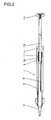
- FIG. 1is an external perspective view of an intraocular lens implanting device relating to the present invention
- FIG. 2is a cross-sectional view of the same
- FIG. 3is a partial exploded view of the intraocular lens implanting device.
- the general configuration of the intraocular lens implanting device 1 to which the present invention is appliedhas a cartridge 3 as a storage part for an intraocular lens 2, a cylindrical hand piece 5 as a main body in which the cartridge 3 is fastened at one end and a holding flange 4 is fixed in place at the other end, and a plunger 6 that passes through the hand piece 5 and is integrated with a push rod 13.
- a distal end 6a of the plunger 6is configured from a base part 7 and a protuberance 8.
- the intraocular lens 2is stored in the interior, and the distal end is inserted into the eyeball through an incision in the eyeball tissue to discharge the lens into the eyeball.
- the cartridgehas a substantially hollow cylindrical shape, which is tapered at one end.
- the end of the cartridge 3 on the side nearer to the operatorhas an intraocular lens insertion hole 3a, and the other end, which is the distal end, has an intraocular lens discharge hole 3b.
- the insertion hole 3ais used to fold and load the intraocular lens 2 into the cartridge 3, and is provided with an insertion groove 3c in the cylindrical part. This insertion groove 3c allows the intraocular lens 2 to be folded and easily loaded into the cartridge 3 by using an insertion implement (not shown).
- the incisionis formed at a slant to make it easier to insert the discharge hole 3b positioned at the distal end of the cartridge 3 into the incision in the eyeball tissue. Furthermore, two winged parts 3d for fastening the cartridge 3 in the hand piece 5 are provided on the sides of the cartridge 3.
- the cartridge 3 as the storage part of the intraocular lens and the hand piece 5 as the main bodyare configured separately, but the cartridge 3 and the hand piece 5 can also be configured integrally.
- the hand piece 5has a guiding part 5a formed in a semicircular arc in cross section in the side surface nearer to the distal end, and this guiding part has guiding paths for guiding the winged parts 3d of the cartridge 3.
- Fastening parts 5bthat enable the winged parts 3d of the cartridge 3 to be fastened are provided in the distal end side of the guiding part 5a.
- a ball bushing 9is mounted between the external peripheral surface of the push rod 13 and the internal peripheral surface of the hand piece 5.
- a cap 11is fixed in place at the other end of the hand piece 5, and a holding flange 4 for allowing the operator to easily hold the hand piece is fixed in place on this cap 11.
- the push rod 13is integrated with the plunger 6 by means of a securing part 12, and is passed through the ball bushing 9 and the holding flange 4 together with the previously described hand piece 5.
- An end plate 14 for making it easier to push and pull the push rod 13is fixed in place on the side of the push rod 13 nearer to the operator.
- the ball bushing 9is one type of bearing, provided with multiple holes 15a around the periphery of a cylindrical ball holder 15, wherein metal balls 16 are disposed in these holes 15a and the push rod 13 can be moved with low friction within the cap 11.
- the advantages of this arrangementare that the push rod 13 can be moved within the cap 11 by means of rolling resistance, and only a small amount of drive force is needed to move the push rod 13.
- the push rod 13needs only to move in the axial direction, and does not need to rotate in the circumferential direction.
- a groove 13ais provided at one location in the outer peripheral surface of the push rod 13, other holes 15b that are separate from the holes 15a are provided in the ball holder 15 to correspond with the groove 13a, and metal balls 17 that are secured in the holes 15b are caused to engage the groove 13a.
- the metal balls 17are also caused to engage an axial groove 5c provided at one location in the internal peripheral surface of the hand piece 5.
- the push rod 13is thereby allowed to move in the axial direction within the cap 11, but is prevented from rotating in the circumferential direction.
- resistance control members 18are disposed in the long holes 15c.
- These resistance control members 18have a slightly larger dimension than the space formed between the minor diameter of the cap 11 and the major diameter of the push rod 13.
- rod-shaped elastic bodies 18composed of silicon rubber or the like are provided. A suitable amount of slip resistance can thereby be applied to the push rod 13 when the push rod 13 is moved in the axial direction within the cap 11, and the movement resistance and speed of the push rod 13 can be controlled.
- the reason the push rod 13 is thus provided with a suitable amount of slip resistanceis because when the resistance of the push rod 13 is too small, the plunger 6 integrated with the push rod 13 cannot maintain its own position without assistance, which makes it more difficult to insert and implant the intraocular lens 2 into the eyeball.
- the intraocular lens implanting device 1 to which the present invention is appliedmakes it possible to control the movement resistance and speed of the push rod 13 by using the ball bushing 9 provided with the resistance control members 18 as described above, and the intraocular lens 2 can therefore be prevented from being suddenly discharged into the eyeball. Since the resistance control members 18 are embedded in the long holes 15c in the ball holder 15, durability can be improved in comparison with a configuration in which the resistance control members 18 are embedded within the hand piece 5 or the cap 11. Furthermore, durability can be further improved if the rod-shaped resistance control members 18 embedded in the long holes 15c of the ball holder 15 are curved into arc shapes.
- the intraocular lens implanting device 1 described aboveuses a ball bushing 9 as a member for controlling the movement resistance and speed of the push rod 13, but a sliding bearing made of a resin as a low-friction material can also be used instead of the ball bushing 9.
- Teflon (registered trademark) and PEEKare examples of a resin material having a low coefficient of friction.
- a sliding bearing manufactured from these resin materialsis less expensive than a ball bushing 9 and has the advantage of keeping production costs low.
- the intraocular lens implanting device 1 to which the present invention is appliedis a medical implement, and the materials of the structural components of this implement must therefore be physically and chemically stable. Particularly, the material used in the region inserted into the eye must be guaranteed to be biologically stable. Possible examples include materials that are approved as implant materials by the FDA (Food and Drug Administration), materials that are standardized as implant materials by the ISO (International Standardization Organization), or materials that are confirmed to be free of problems as a result of tests performed according to ISO10993. Examples of materials that fulfill these requirements include polyethylene or polypropylene for the material of the cartridge, and a titanium alloy or martensite stainless steel for the material of the plunger.
- the intraocular lens implanting device 1 to which the present invention is appliedis a device that an operator can use with one hand, and the dimensions and weight of the intraocular lens implanting device 1 are also important factors. Specifically, it is difficult to operate the device with one hand if the dimensions are either too large or too small. There is no inconvenience for the device to be lightweight, but a device that is too heavy increases the burden on the operator. According to empirical fact, the maximum length of the entire device with the push rod 13 extended is preferably 200 mm or less, and more preferably 160 mm or less. The weight of the entire intraocular lens implanting device 1 is preferably 40 g or less, and more preferably 30 g or less.
- a material having a high specific strengthi.e., a material having a high strength per unit weight is used as the material of the primary components.
- a titanium alloyis primarily used, but stainless steel is also used for the screws and other small components.
- the intraocular lens implanting device 1 to which the present invention is appliedrequires no maintenance under normally assumed conditions.
- the devicecan retain its initial performance after a period of two years or more, without any special maintenance. It has also been confirmed that the device can retain its initial performance even after being repeatedly treated 200 or more times when the treatment is high-pressure sterilization conducted at 130°C for fifteen minutes. Furthermore, it has been confirmed that the device retains its initial performance when a thrust load of 800 g is applied to the distal end of the plunger 6, even when such a load is repeatedly applied 100 or more times. It has also been confirmed that the device can withstand 10,000 operating cycles in a load-free state in which no load is applied to the plunger 6.
- FIG. 4shows different examples of the shape of the distal end of the plunger 6, wherein (a) depicts a case in which the protuberance 8 is provided in the top center of the distal end of the base part 7, (b) depicts a case in which the protuberance 8 is provided at the lower right of the distal end of the base part 7, and (c) depicts a case in which the protuberance 8 is provided in the bottom center of the distal end of the base part 7.
- the protuberance 8is provided to one location on the distal end of the base part 7 whose distal end is a flat surface, and the protuberance 8 is provided at a position displaced from the axial center of the plunger 6.
- the differenceis that the positions of the protuberance 8 shown in (a) and (c) are provided in the longitudinal axis center 6b of the distal end surface of the plunger 6, while the position of the protuberance 8 shown in (b) is provided at a position displaced from the longitudinal axis center 6b of the distal end surface of the plunger 6.
- arbitrary valuescan be used for the dimensions of the distal end 6a of the plunger 6 and the protuberance 8, but appropriate values exist for the distal end 6a of the plunger 6 and the protuberance 8 because the intraocular lens 2 will be inserted into the eye.
- typical dimensions for the intraocular lens 2are 6 mm for the diameter of the optical part, 0.7 mm for the center thickness of the optical part, and 0.25 mm for the peripheral thickness of the optical part.
- a width of 1.2 mm and a height of about 1.5 mmare suitable dimensions for the distal end 6a of the plunger 6.
- a diameter and height of about 0.3 mmare suitable dimensions for the protuberance 8.
- the plunger 6is integrated with the push rod 13 and is pushed and pulled by the operator.
- the intraocular lens 2 stored in the cartridge 3is pushed out and implanted into the eye by the distal end 6a of the plunger 6.
- the intraocular lensis made of bendable material and is highly elastic. Therefore, when the periphery 2a of the intraocular lens 2 is pressed in, the periphery 2a of the intraocular lens deforms comparatively easily, but returns to its pre-deformation state when the pressure is released.
- the protuberance 8comes into contact with the periphery 2a of the intraocular lens, and the periphery 2a of the intraocular lens is first pressed by the protuberance 8.
- the optimum shape for the protuberance 8is a hemisphere or a combination of a hemisphere and a cylindrical pillar, and since the protuberance has a small surface area, the periphery 2a of the intraocular lens in contact with the protuberance 8 is subjected to comparatively high surface pressure.
- the protuberance 8presses into the periphery 2a of the intraocular lens and causes the contact part of the intraocular lens to undergo elastic deformation.
- the periphery 2a of the intraocular lenscomes into contact with a flat surface 7a at the distal end of the base part 7. Therefore, the amount of deformation in the intraocular lens 2 caused by the protuberance 8 is limited by the height of the protuberance 8 from the distal end surface 7a of the bottom part.
- the intraocular lens 2is pressed by the plunger 6, the periphery 2a of the intraocular lens is pressed by the flat surface 7a at the distal end of the base part 7. Therefore, the height of the protuberance 8 is set so as to not exceed the elasticity limit of the material of the intraocular lens 2.
- the shape of the protuberance 8is not limited to a hemisphere or a combination of a hemisphere and a cylindrical pillar, and may be a cylindrical pillar alone or an elliptical pillar.
- the reason that the protuberance 8 is provided at a position displaced from the axial center of the plunger 6, i.e., at the periphery of the distal end surface 7a at the base that is offset from the axial center of the plunger 6,is that the protuberance 8 can then easily come into contact with the periphery 2a of the intraocular lens, which is bent into the shape of a U. Because of this, the position to which the protuberance 8 is provided should be the periphery of the distal end surface 7a at the base, and this position is not limited to the examples shown in FIGS. 4(a), (b), and (c) .
- FIG. 5shows a plan view of the intraocular lens 2.
- the intraocular lens 2is composed of an optical part 2 as a lens main body having a substantially circular plate shape, and two barb-shaped supporting parts 2b for fixing the position of the optical part 2.
- the lensis made of a soft resin material, including the optical part 2, and can easily undergo elastic deformation.
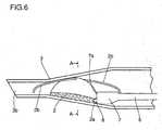
- FIG. 6shows the manner in which the optical part 2 is folded into a substantial U shape and stored in the cartridge 3, and is pressed and moved by the distal end of the plunger 6. Specifically, this drawing is an axial cross-sectional view of the cartridge 3.
- FIG. 7is a view from the arrows A-A in FIG. 6 .
- the intraocular lens 2is stored in the cartridge 3 so that the mounts of the two support parts 2b are positioned at the two ends of the U shape. Therefore, after the lens is stored in the cartridge 3, the two support parts 2b are disposed on the front and back of the cartridge 3 in the axial direction, as shown in FIG. 6 .
- the distal end 6a of the plunger 6comes into contact with the periphery 2a of the optical part of the optical part 2 so as to avoid the barb-shaped support parts 2b.
- the operatoruses one hand to push out the intraocular lens 2 from the distal end of the cartridge 3 and implant the lens in the eyeball.
- the lensis implanted by the procedure shown in the drawings in FIG. 8 .
- the protuberance 8 provided at the distal end of the base part 7 of the plunger 6comes into contact with and presses against the periphery 2a of the optical part, and also presses against the flat surface 7a of the distal end of the base part 7 of the plunger 6 to move the intraocular lens 2 closer to the distal end of the cartridge 3.
- the intraocular lens 2generates sliding resistance by being caused to slide against the internal peripheral surface of the cartridge 3.
- the intraocular lens 2moves toward the distal end within the cartridge 3 when the plunger 6 applies pressure greater than this sliding resistance.
- the protuberance 8 at the distal end of the plunger 6causes the periphery 2a of the optical part to undergo significant elastic deformation, and the flat surface 7a of the base part 7 of the plunger 6 also elastically deforms the periphery 2a of the optical part with a certain amount of pressure.
- the distal end 6a of the plunger 6is essentially fixed in place on the periphery 2a of the intraocular lens, and the protuberance 8 at the distal end of the plunger 6 exhibits the effect of an anchor. Therefore, the operator can easily move the intraocular lens 2 within the cartridge 3 while keeping the intraocular lens 2 in the intended alignment.
- the discharge hole 3b of the cartridge 3is inserted into the incision 19 in the eyeball, and the distal end support part 2b is inserted into the eye, as shown in (a).
- the plunger 6then pushes out the intraocular lens 2 in small increments while the entire intraocular lens implanting device 1 is slowly rotated to open the optical part 2, as shown in (b) and (c).
- the intraocular lens 2is not necessarily moved to the optimal position in the eyeball in this stage. In many cases, the position of the intraocular lens 2 in the eyeball must be adjusted.
- the drawing in (d)shows an example of this, wherein the position of the intraocular lens 2 is adjusted with the aid of the plunger 6 by using the fact that the protuberance 8 provided at the distal end of the plunger 6 is still pushed into the periphery 2a of the optical part.
- the other supporting part 2bis released from the cartridge 3 as shown in (e) after the position of the intraocular lens 2 has been adjusted.
- the intraocular lens 2When the intraocular lens 2 is moved within the cartridge 3 in this manner, it is possible to easily control the alignment of the intraocular lens 2 by using the anchor effect in which the protuberance 8 at the distal end of the plunger 6 presses against the periphery 2a of the optical part. Furthermore, the intraocular lens 2 is easily aligned to the desired position inside the eyeball, because the anchor effect remains for some time even after the intraocular lens 2 is discharged from the discharge hole 3b of the cartridge 3 inserted into the eyeball through the incision 19 and has returned to its original plate shape inside the eyeball.
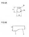
- FIG. 9shows a plunger 6 in which two protuberances are provided at the distal end, wherein (a) is a front view and (b) is a side view.
- a protuberance 8a provided at the bottom right of the front viewexhibits the same anchor effect as the protuberance shown in FIG. 4 .
- This protuberancecomes in contact with the periphery of the intraocular lens 2 to elastically deform the intraocular lens 2, and introduces the intraocular lens 2 into the eyeball from the cartridge 3.
- a diameter of 0.2 mm and a height of about 0.25 mmare suitable dimensions for the protuberance 8a.
- the protuberance 8b in the top center of the front viewis designed to come into contact with the surface of the intraocular lens 2 inside the eyeball and adjust the position of the intraocular lens 2 after the intraocular lens 2 is discharged into the eyeball from the cartridge 3. Providing this protuberance 8b makes it possible to easily adjust the position of the intraocular lens 2 inside the eyeball.
- a diameter of 0.26 mm and a height of about 0.43 mmare suitable dimensions for the protuberance 8b.
- the present inventionwas applied to an intraocular lens implanting device 1 in which the plunger 6 was moved by pushing and pulling directly in the axial direction, but it is apparent that the present invention can also be applied to a screw-style intraocular lens implanting device wherein the plunger 6 is moved by the rotation of the push rod.
- FIGS. 6 through 8an example was described in which the intraocular lens was folded into a substantial U shape, but the cross-sectional shape of the intraocular lens when folded is not limited to the shape of a U, and the lens can be folded into various other cross-sectional shapes.
Landscapes
- Health & Medical Sciences (AREA)
- Ophthalmology & Optometry (AREA)
- Cardiology (AREA)
- Oral & Maxillofacial Surgery (AREA)
- Transplantation (AREA)
- Engineering & Computer Science (AREA)
- Biomedical Technology (AREA)
- Heart & Thoracic Surgery (AREA)
- Vascular Medicine (AREA)
- Life Sciences & Earth Sciences (AREA)
- Animal Behavior & Ethology (AREA)
- General Health & Medical Sciences (AREA)
- Public Health (AREA)
- Veterinary Medicine (AREA)
- Prostheses (AREA)
Description
- The present invention relates to an implanting device for implanting an intraocular lens into an eyeball in place of a crystalline lens which has been extracted by cataract surgery; and specifically relates to an intraocular lens implanting device wherein a foldable intraocular lens is stored in a storage part, pressed in with a plunger, passed through an incision in the eyeball tissue, and implanted therein.
- Artificial crystalline lenses are often implanted in the eye to replace a crystalline lens which has been extracted via cataract surgery. In a modern cataract surgery and the accompanying implantation of an artificial crystalline lens, the most important matter of concern is that the surgery be minimally invasive. Making the incision in the eyeball tissue smaller is expected to have the effect of alleviating postoperative astigmatism, and making the incision smaller as well as reducing the surgery time are expected to reduce the occurrence of postoperative inflammation. Specifically, making a smaller incision in the eyeball tissue and reducing the time of a series of surgeries has the merits of promoting faster post-op eyesight recovery and alleviating the burdens imposed by surgery on both the patient and the surgeon.
WO 97/15263 A1 US 4 934 363 A discloses the preamble of claim 1.- Phacoemulsification is often used in modern cataract surgery, and it is possible to leave the crystalline lens capsule while extracting an opacified crystalline lens nucleus through an incision of about 2.8 mm in the eyeball tissue.
- An artificial intraocular lens implanted in place of the extracted crystalline lens is implanted in the remaining crystalline lens capsule. Following the invention of foldable intraocular lenses, it has even been possible to insert an intraocular lens having an optical diameter of 6 mm into an incision of about 4 mm in the eyeball tissue by folding the lens in half. Furthermore, to insert an artificial intraocular lens into the eye through a small incision, a method has recently been proposed wherein the intraocular lens is folded and stored in a storage cartridge, and is pressed in and implanted with a plunger. It is possible to implant an artificial intraocular lens into the eye without widening the incision made in the eyeball tissue for phacoemulsification purposes.
- One example of a specific method for implanting the artificial intraocular lens into the eyeball by using a cartridge and a plunger is an intraocular lens insertion system (see Patent Document 1, for example) configured from a plunger, a cartridge, and a hand piece as a cylindrical main body. This intraocular lens insertion system has a lens compartment in the cartridge, and the intraocular lens placed in the lens compartment can be folded over by closing the lens compartment. After the lens is folded, the cartridge is mounted on the hand piece and the plunger is pressed in, whereby the intraocular lens can be implanted into the eye.
- Since the distal end of the plunger has a unique bifurcated shape, the supporting part of the intraocular lens can be prevented from being crushed between and damaged by the inner wall of the cartridge and the distal end of the plunger when the intraocular lens is passed through the cartridge interior. Also, after the intraocular lens is inserted into the eye, the distal end of the bifurcated plunger can be used to adjust the position of the intraocular lens to a specific position.
Patent Document 1: Domestic Republication No. 8-505540 - However, the conventional technique described above has the following problems. One problem arises from the distal end of the plunger being bifurcated and the middle being hollowed. Specifically, since the plunger has a complicated shape having two protuberances for holding down the periphery of the intraocular lens, the pressure applied to the intraocular lens from the plunger when the intraocular lens is pushed out may concentrate in a particular region of the distal end of the plunger, and may damage the optical surface of the intraocular lens. Another problem is that since the structure is complicated, production costs are high.
- Another problem arises from the folding mechanism being attached to the cartridge itself. In the method for implanting an intraocular lens into the eyeball by using an insertion cylinder and a plunger, a cartridge is used wherein the insertion cylinder, the lens compartment, and the lens-folding part are formed integrally. The structure of the folding part therefore has restrictions, and it has been difficult to fold the intraocular lens into the desired shape. As a result, the operator must be skilled and experienced.
- Specifically, the intraocular lens is composed of an optical part having a substantially circular shape in plan view, and multiple barb-shaped supporting parts for holding the lens at a specific position in the eye. The positional relationships between the optical part and the supporting parts is extremely important in the processes for folding the intraocular lens, inserting the lens into the eye, and setting the lens in place in the eye. If these positional relationships are inadequate or occasionally unstable, this causes problems in that a long time is spent setting the intraocular lens in place at a specific position, and a large burden is imposed on the operator and the patient. Various shapes are possible for the supporting parts of the intraocular lens, such as plate shapes instead of barb shapes, but the same problems are encountered with an intraocular lens having plate-shaped supporting parts.
- The present invention was designed in order to resolve the problems encountered with the conventional technique described above, and an object thereof is to provide an intraocular lens implanting device wherein the intraocular lens is prevented from rotating improperly when the intraocular lens is inserted into the eye, the intraocular lens can be safely and reliably inserted into the eyeball, and the device has an ophthalmic hooking function whereby the position of the intraocular lens can be adjusted after the intraocular lens has entered the eyeball.
- This object is achieved by the subject-matter according to claim 1. The dependent claims refer to preferred embodiments of the invention.
- The invention according to a first aspect provides an intraocular lens implanting device as disclosed in the appended claims for inserting an intraocular lens into an eyeball through an incision in the eyeball tissue, the device characterized in comprising a cylindrical main body, a storage part for the Intraocular lens that is integrated with or is separate from the main body, and a plunger for pushing out the intraocular lens stored in the storage part and discharging the lens into the eyeball, wherein a distal end of the plunger has a base part and a protuberance.
- A distal end of the base part is a flat surface.
- The protuberance is provided at one location on the distal end of the base part.
- The protuberance is provided at a position displaced from the axial center of the plunger.
- The invention according to second aspect is the intraocular lens implanting device according to the first aspect, characterized in that the protuberance is provided at a position displaced from the longitudinal axial center on the distal end surface of the plunger.
- The invention according to third aspect is the intraocular lens implanting device according to any of previous aspect, characterized in that the shape of the protuberance is a cylindrical pillar, a hemisphere, or a combination of a cylindrical pillar and a hemisphere.
- A contact part of an intraocular lens is elastically deformed by the (*1) protuberance when the intraocular lens stored in the (*1) storage part is pushed and moved by a distal end of the (*1) plunger.
- According to the intraocular lens implanting device of the first aspect, the intraocular lens is not likely to be scratched because the pressure applied to the intraocular lens from the distal end of the plunger is properly distributed when the intraocular lens is passed through the interior of the cartridge as a storage part. The device can also have an ophthalmic hooking function because the protuberance in the distal end of the plunger can move and set the intraocular lens in place at a specific position in the eye even after the intraocular lens has been inserted into the eyeball.
- The intraocular lens can be pushed out in a straight line.
- The intraocular lens can be elastically deformed in a reliable manner by a specific amount.
- Since the protuberance is offset from the axial center of the plunger, the position of the intraocular lens implanted in the eyeball can easily be adjusted by somewhat rotating the hand piece main body.
- According to the intraocular lens implanting device of the second aspect, the position of the intraocular lens can be more easily adjusted, and there is less danger of the supporting parts of the intraocular lens being damaged.
- According to the intraocular lens implanting device of the third aspect, the intraocular lens can be elastically deformed in a reliable manner by a specific amount, and the intraocular lens is not scratched.
- The position of the intraocular lens is easily adjusted when the intraocular lens is inserted and implanted into the eyeball.
- Embodiments of the present invention will now be described with reference to the drawings.
FIG. 1 is an external perspective view of an intraocular lens implanting device relating to the present invention, andFIG. 2 is a cross-sectional view of the same.FIG. 3 is a partial exploded view of the intraocular lens implanting device. - First, an intraocular lens implanting device 1 to which the present invention is applied will be described. The general configuration of the intraocular lens implanting device 1 to which the present invention is applied has a
cartridge 3 as a storage part for anintraocular lens 2, acylindrical hand piece 5 as a main body in which thecartridge 3 is fastened at one end and aholding flange 4 is fixed in place at the other end, and aplunger 6 that passes through thehand piece 5 and is integrated with apush rod 13. Adistal end 6a of theplunger 6 is configured from abase part 7 and aprotuberance 8. - In the
cartridge 3, theintraocular lens 2 is stored in the interior, and the distal end is inserted into the eyeball through an incision in the eyeball tissue to discharge the lens into the eyeball. The cartridge has a substantially hollow cylindrical shape, which is tapered at one end. The end of thecartridge 3 on the side nearer to the operator has an intraocularlens insertion hole 3a, and the other end, which is the distal end, has an intraocularlens discharge hole 3b. Theinsertion hole 3a is used to fold and load theintraocular lens 2 into thecartridge 3, and is provided with aninsertion groove 3c in the cylindrical part. Thisinsertion groove 3c allows theintraocular lens 2 to be folded and easily loaded into thecartridge 3 by using an insertion implement (not shown). The incision is formed at a slant to make it easier to insert thedischarge hole 3b positioned at the distal end of thecartridge 3 into the incision in the eyeball tissue. Furthermore, twowinged parts 3d for fastening thecartridge 3 in thehand piece 5 are provided on the sides of thecartridge 3. - In the present embodiment, the
cartridge 3 as the storage part of the intraocular lens and thehand piece 5 as the main body are configured separately, but thecartridge 3 and thehand piece 5 can also be configured integrally. - The
hand piece 5 has a guidingpart 5a formed in a semicircular arc in cross section in the side surface nearer to the distal end, and this guiding part has guiding paths for guiding thewinged parts 3d of thecartridge 3. Fasteningparts 5b that enable thewinged parts 3d of thecartridge 3 to be fastened are provided in the distal end side of the guidingpart 5a. At the other end of thehand piece 5, aball bushing 9 is mounted between the external peripheral surface of thepush rod 13 and the internal peripheral surface of thehand piece 5. Furthermore, acap 11 is fixed in place at the other end of thehand piece 5, and a holdingflange 4 for allowing the operator to easily hold the hand piece is fixed in place on thiscap 11. - The
push rod 13 is integrated with theplunger 6 by means of a securingpart 12, and is passed through theball bushing 9 and the holdingflange 4 together with the previously describedhand piece 5. Anend plate 14 for making it easier to push and pull thepush rod 13 is fixed in place on the side of thepush rod 13 nearer to the operator. - The
ball bushing 9 is one type of bearing, provided withmultiple holes 15a around the periphery of acylindrical ball holder 15, whereinmetal balls 16 are disposed in theseholes 15a and thepush rod 13 can be moved with low friction within thecap 11. Specifically, the advantages of this arrangement are that thepush rod 13 can be moved within thecap 11 by means of rolling resistance, and only a small amount of drive force is needed to move thepush rod 13. Thepush rod 13 needs only to move in the axial direction, and does not need to rotate in the circumferential direction. In view of this, agroove 13a is provided at one location in the outer peripheral surface of thepush rod 13,other holes 15b that are separate from theholes 15a are provided in theball holder 15 to correspond with thegroove 13a, andmetal balls 17 that are secured in theholes 15b are caused to engage thegroove 13a. Themetal balls 17 are also caused to engage anaxial groove 5c provided at one location in the internal peripheral surface of thehand piece 5. Thepush rod 13 is thereby allowed to move in the axial direction within thecap 11, but is prevented from rotating in the circumferential direction. - Furthermore, four
long holes 15c are provided in the periphery of theball holder 15 of theball bushing 9, andresistance control members 18 are disposed in thelong holes 15c. Theseresistance control members 18 have a slightly larger dimension than the space formed between the minor diameter of thecap 11 and the major diameter of thepush rod 13. Specifically, rod-shapedelastic bodies 18 composed of silicon rubber or the like are provided. A suitable amount of slip resistance can thereby be applied to thepush rod 13 when thepush rod 13 is moved in the axial direction within thecap 11, and the movement resistance and speed of thepush rod 13 can be controlled. The reason thepush rod 13 is thus provided with a suitable amount of slip resistance is because when the resistance of thepush rod 13 is too small, theplunger 6 integrated with thepush rod 13 cannot maintain its own position without assistance, which makes it more difficult to insert and implant theintraocular lens 2 into the eyeball. - The intraocular lens implanting device 1 to which the present invention is applied makes it possible to control the movement resistance and speed of the
push rod 13 by using the ball bushing 9 provided with theresistance control members 18 as described above, and theintraocular lens 2 can therefore be prevented from being suddenly discharged into the eyeball. Since theresistance control members 18 are embedded in thelong holes 15c in theball holder 15, durability can be improved in comparison with a configuration in which theresistance control members 18 are embedded within thehand piece 5 or thecap 11. Furthermore, durability can be further improved if the rod-shapedresistance control members 18 embedded in thelong holes 15c of theball holder 15 are curved into arc shapes. - The intraocular lens implanting device 1 described above uses a
ball bushing 9 as a member for controlling the movement resistance and speed of thepush rod 13, but a sliding bearing made of a resin as a low-friction material can also be used instead of theball bushing 9. Teflon (registered trademark) and PEEK are examples of a resin material having a low coefficient of friction. A sliding bearing manufactured from these resin materials is less expensive than aball bushing 9 and has the advantage of keeping production costs low. - The intraocular lens implanting device 1 to which the present invention is applied is a medical implement, and the materials of the structural components of this implement must therefore be physically and chemically stable. Particularly, the material used in the region inserted into the eye must be guaranteed to be biologically stable. Possible examples include materials that are approved as implant materials by the FDA (Food and Drug Administration), materials that are standardized as implant materials by the ISO (International Standardization Organization), or materials that are confirmed to be free of problems as a result of tests performed according to ISO10993. Examples of materials that fulfill these requirements include polyethylene or polypropylene for the material of the cartridge, and a titanium alloy or martensite stainless steel for the material of the plunger.
- It is assumed that the intraocular lens implanting device 1 to which the present invention is applied is a device that an operator can use with one hand, and the dimensions and weight of the intraocular lens implanting device 1 are also important factors. Specifically, it is difficult to operate the device with one hand if the dimensions are either too large or too small. There is no inconvenience for the device to be lightweight, but a device that is too heavy increases the burden on the operator. According to empirical fact, the maximum length of the entire device with the
push rod 13 extended is preferably 200 mm or less, and more preferably 160 mm or less. The weight of the entire intraocular lens implanting device 1 is preferably 40 g or less, and more preferably 30 g or less. - In view of this, in the intraocular lens implanting device 1 to which the present invention is applied, a material having a high specific strength, i.e., a material having a high strength per unit weight is used as the material of the primary components. Specifically, a titanium alloy is primarily used, but stainless steel is also used for the screws and other small components. As a result of using such materials, it is possible to attain an intraocular lens implanting device 1 that is free of rust, is lightweight, and has superior durability as described hereinbelow.
- The intraocular lens implanting device 1 to which the present invention is applied requires no maintenance under normally assumed conditions. The device can retain its initial performance after a period of two years or more, without any special maintenance. It has also been confirmed that the device can retain its initial performance even after being repeatedly treated 200 or more times when the treatment is high-pressure sterilization conducted at 130°C for fifteen minutes. Furthermore, it has been confirmed that the device retains its initial performance when a thrust load of 800 g is applied to the distal end of the
plunger 6, even when such a load is repeatedly applied 100 or more times. It has also been confirmed that the device can withstand 10,000 operating cycles in a load-free state in which no load is applied to theplunger 6. - The following is a description, made with reference to
FIG. 4 , of the shape of thedistal end 6a of theplunger 6, which is in the core portion of the present invention. Thedistal end 6a of theplunger 6 is configured from abase part 7 and aprotuberance 8.FIG. 4 shows different examples of the shape of the distal end of theplunger 6, wherein (a) depicts a case in which theprotuberance 8 is provided in the top center of the distal end of thebase part 7, (b) depicts a case in which theprotuberance 8 is provided at the lower right of the distal end of thebase part 7, and (c) depicts a case in which theprotuberance 8 is provided in the bottom center of the distal end of thebase part 7. The common aspect shared by these examples is that theprotuberance 8 is provided to one location on the distal end of thebase part 7 whose distal end is a flat surface, and theprotuberance 8 is provided at a position displaced from the axial center of theplunger 6. The difference is that the positions of theprotuberance 8 shown in (a) and (c) are provided in thelongitudinal axis center 6b of the distal end surface of theplunger 6, while the position of theprotuberance 8 shown in (b) is provided at a position displaced from thelongitudinal axis center 6b of the distal end surface of theplunger 6. - In each example shown in
FIG. 4 , arbitrary values can be used for the dimensions of thedistal end 6a of theplunger 6 and theprotuberance 8, but appropriate values exist for thedistal end 6a of theplunger 6 and theprotuberance 8 because theintraocular lens 2 will be inserted into the eye. For example, typical dimensions for theintraocular lens 2 are 6 mm for the diameter of the optical part, 0.7 mm for the center thickness of the optical part, and 0.25 mm for the peripheral thickness of the optical part. In this case, a width of 1.2 mm and a height of about 1.5 mm are suitable dimensions for thedistal end 6a of theplunger 6. A diameter and height of about 0.3 mm are suitable dimensions for theprotuberance 8. - The
plunger 6 is integrated with thepush rod 13 and is pushed and pulled by the operator. Theintraocular lens 2 stored in thecartridge 3 is pushed out and implanted into the eye by thedistal end 6a of theplunger 6. The intraocular lens is made of bendable material and is highly elastic. Therefore, when theperiphery 2a of theintraocular lens 2 is pressed in, theperiphery 2a of the intraocular lens deforms comparatively easily, but returns to its pre-deformation state when the pressure is released. Each of the distal ends 6a of theplungers 6 shown inFIG. 4 is used to press on theperiphery 2a of the intraocular lens, theprotuberance 8 comes into contact with theperiphery 2a of the intraocular lens, and theperiphery 2a of the intraocular lens is first pressed by theprotuberance 8. The optimum shape for theprotuberance 8 is a hemisphere or a combination of a hemisphere and a cylindrical pillar, and since the protuberance has a small surface area, theperiphery 2a of the intraocular lens in contact with theprotuberance 8 is subjected to comparatively high surface pressure. Theprotuberance 8 presses into theperiphery 2a of the intraocular lens and causes the contact part of the intraocular lens to undergo elastic deformation. As theprotuberance 8 causes theintraocular lens 2 to undergo elastic deformation, theperiphery 2a of the intraocular lens comes into contact with aflat surface 7a at the distal end of thebase part 7. Therefore, the amount of deformation in theintraocular lens 2 caused by theprotuberance 8 is limited by the height of theprotuberance 8 from thedistal end surface 7a of the bottom part. When theintraocular lens 2 is pressed by theplunger 6, theperiphery 2a of the intraocular lens is pressed by theflat surface 7a at the distal end of thebase part 7. Therefore, the height of theprotuberance 8 is set so as to not exceed the elasticity limit of the material of theintraocular lens 2. - The shape of the
protuberance 8 is not limited to a hemisphere or a combination of a hemisphere and a cylindrical pillar, and may be a cylindrical pillar alone or an elliptical pillar. - The reason that the
protuberance 8 is provided at a position displaced from the axial center of theplunger 6, i.e., at the periphery of thedistal end surface 7a at the base that is offset from the axial center of theplunger 6, is that theprotuberance 8 can then easily come into contact with theperiphery 2a of the intraocular lens, which is bent into the shape of a U. Because of this, the position to which theprotuberance 8 is provided should be the periphery of thedistal end surface 7a at the base, and this position is not limited to the examples shown inFIGS. 4(a), (b), and (c) . - The following is a description, made with reference to
FIGS. 5 through 7 , of the action when theintraocular lens 2 is inserted and implanted into an eyeball by using the intraocular lens implanting device 1 to which the present invention is applied.FIG. 5 shows a plan view of theintraocular lens 2. Theintraocular lens 2 is composed of anoptical part 2 as a lens main body having a substantially circular plate shape, and two barb-shaped supportingparts 2b for fixing the position of theoptical part 2. The lens is made of a soft resin material, including theoptical part 2, and can easily undergo elastic deformation.FIG. 6 shows the manner in which theoptical part 2 is folded into a substantial U shape and stored in thecartridge 3, and is pressed and moved by the distal end of theplunger 6. Specifically, this drawing is an axial cross-sectional view of thecartridge 3.FIG. 7 is a view from the arrows A-A inFIG. 6 . - The
intraocular lens 2 is stored in thecartridge 3 so that the mounts of the twosupport parts 2b are positioned at the two ends of the U shape. Therefore, after the lens is stored in thecartridge 3, the twosupport parts 2b are disposed on the front and back of thecartridge 3 in the axial direction, as shown inFIG. 6 . Thedistal end 6a of theplunger 6 comes into contact with theperiphery 2a of the optical part of theoptical part 2 so as to avoid the barb-shapedsupport parts 2b. - After the
cartridge 3 that stores theintraocular lens 2 is mounted in the intraocular lens implanting device 1, the operator uses one hand to push out theintraocular lens 2 from the distal end of thecartridge 3 and implant the lens in the eyeball. Specifically, the lens is implanted by the procedure shown in the drawings inFIG. 8 . First, theprotuberance 8 provided at the distal end of thebase part 7 of theplunger 6 comes into contact with and presses against theperiphery 2a of the optical part, and also presses against theflat surface 7a of the distal end of thebase part 7 of theplunger 6 to move theintraocular lens 2 closer to the distal end of thecartridge 3. At this time, theintraocular lens 2 generates sliding resistance by being caused to slide against the internal peripheral surface of thecartridge 3. Theintraocular lens 2 moves toward the distal end within thecartridge 3 when theplunger 6 applies pressure greater than this sliding resistance. - Since the
intraocular lens 2 is made from a soft elastic material, theprotuberance 8 at the distal end of theplunger 6 causes theperiphery 2a of the optical part to undergo significant elastic deformation, and theflat surface 7a of thebase part 7 of theplunger 6 also elastically deforms theperiphery 2a of the optical part with a certain amount of pressure. As a result, thedistal end 6a of theplunger 6 is essentially fixed in place on theperiphery 2a of the intraocular lens, and theprotuberance 8 at the distal end of theplunger 6 exhibits the effect of an anchor. Therefore, the operator can easily move theintraocular lens 2 within thecartridge 3 while keeping theintraocular lens 2 in the intended alignment. - The following is a simple description, made with reference to
FIG. 8 , of the process for inserting and implanting theintraocular lens 2 into the eyeball. Thedischarge hole 3b of thecartridge 3 is inserted into theincision 19 in the eyeball, and the distalend support part 2b is inserted into the eye, as shown in (a). Theplunger 6 then pushes out theintraocular lens 2 in small increments while the entire intraocular lens implanting device 1 is slowly rotated to open theoptical part 2, as shown in (b) and (c). Theintraocular lens 2 is not necessarily moved to the optimal position in the eyeball in this stage. In many cases, the position of theintraocular lens 2 in the eyeball must be adjusted. The drawing in (d) shows an example of this, wherein the position of theintraocular lens 2 is adjusted with the aid of theplunger 6 by using the fact that theprotuberance 8 provided at the distal end of theplunger 6 is still pushed into theperiphery 2a of the optical part. The other supportingpart 2b is released from thecartridge 3 as shown in (e) after the position of theintraocular lens 2 has been adjusted. - When the
intraocular lens 2 is moved within thecartridge 3 in this manner, it is possible to easily control the alignment of theintraocular lens 2 by using the anchor effect in which theprotuberance 8 at the distal end of theplunger 6 presses against theperiphery 2a of the optical part. Furthermore, theintraocular lens 2 is easily aligned to the desired position inside the eyeball, because the anchor effect remains for some time even after theintraocular lens 2 is discharged from thedischarge hole 3b of thecartridge 3 inserted into the eyeball through theincision 19 and has returned to its original plate shape inside the eyeball. - Next, an example will be described in which two protuberances are provided at the distal end of the
plunger 6, unlike inFIG. 4 .FIG. 9 shows aplunger 6 in which two protuberances are provided at the distal end, wherein (a) is a front view and (b) is a side view. Aprotuberance 8a provided at the bottom right of the front view exhibits the same anchor effect as the protuberance shown inFIG. 4 . This protuberance comes in contact with the periphery of theintraocular lens 2 to elastically deform theintraocular lens 2, and introduces theintraocular lens 2 into the eyeball from thecartridge 3. Assuming that the width W of thedistal end 6a of theplunger 6 is 1.2 mm and the height H is 1.5 mm, a diameter of 0.2 mm and a height of about 0.25 mm are suitable dimensions for theprotuberance 8a. Theprotuberance 8b in the top center of the front view is designed to come into contact with the surface of theintraocular lens 2 inside the eyeball and adjust the position of theintraocular lens 2 after theintraocular lens 2 is discharged into the eyeball from thecartridge 3. Providing thisprotuberance 8b makes it possible to easily adjust the position of theintraocular lens 2 inside the eyeball. A diameter of 0.26 mm and a height of about 0.43 mm are suitable dimensions for theprotuberance 8b. - Several examples of the present invention were described above, but the present invention is not limited to these examples, and various modifications can be made within the scope of the appended claims. For example, in the examples described above, the present invention was applied to an intraocular lens implanting device 1 in which the
plunger 6 was moved by pushing and pulling directly in the axial direction, but it is apparent that the present invention can also be applied to a screw-style intraocular lens implanting device wherein theplunger 6 is moved by the rotation of the push rod. - In
FIGS. 6 through 8 , an example was described in which the intraocular lens was folded into a substantial U shape, but the cross-sectional shape of the intraocular lens when folded is not limited to the shape of a U, and the lens can be folded into various other cross-sectional shapes. FIG. 1 is an external perspective view of the intraocular lens implanting device according to the present invention;FIG. 2 is a cross-sectional view of the same intraocular lens implanting device;FIG. 3 is a partial exploded view of the same intraocular lens implanting device;FIG. 4 is a perspective view showing the shape of the distal end of the plunger of the same device;FIG. 5 is a drawing showing a plan view of an intraocular lens;FIG. 6 is a cross-sectional view showing the manner in which the intraocular lens is stored in the cartridge;FIG. 7 is a view from the arrows A-A inFIG. 6 ;FIG. 8 is a schematic view showing the process of implanting the intraocular lens in an eyeball; andFIG. 9 is a drawing showing the shape of the distal end of the plunger in another example.- 1:
- intraocular lens implanting device
- 2:
- intraocular lens
- 3:
- storage part (cartridge)
- 5:
- main body (hand piece)
- 6:
- plunger
- 6a:
- distal end
- 7;
- base part
- 8:
- protruding part (protuberance)
Claims (5)
- An intraocular lens implanting device (1) for inserting an intraocular lens into an eyeball through an incision in the eyeball tissue, said intraocular lens implanting device (1) comprising:a cylindrical main body (5);a storage part (3) for the intraocular lens (2) that is integrated with or is separate from the main body (5); anda plunger (6), defining an axial center, for pushing out the intraocular lens (2) stored in the storage part (3) and discharging the lens (2) into the eyeball, whereina distal end (6a) of the plunger (6) has a base part (7) and a protuberance (8), the base part (7) having a flat distal end surface (7a) that defines a top edge and a bottom edge,the protuberance (8) protrudes distally from a location on the flat distal end surface (7a) of the plunger base part (7) that is offset from the axial center of the plunger (6)andcharacterized in that the location of the protuberance on the flat distal end surface is offset from and between the top and bottom edges of the flat distal end surface (7a) such that pressing the intraocular lens (2) with the plunger (6) causes the protuberance (8) to press into the periphery (2a) of the intraocular lens (2), the contact part of the intraocular lens (2) to undergo elastic deformation, and the periphery (2a) of the intraocular lens (2) to come into contact with the flat distal end surface (7a) of the plunger base part (7) as the elastic deformation of the intraocular lens (2) progresses, thereby limiting an amount of deformation in the intraocular lens (2) caused by the protuberance (8) by a height of the protuberance (8) from the flat distal end surface (7a) of the plunger base part (7).
- The intraocular lens implanting device (1) according to claim 1,characterized in that the protuberance (8) is provided at only one location on the flat distal end surface (7a) of the base part (7).
- The intraocular lens implanting device (1) according to any of claims 1 or 2,characterized in that the protuberance (8) is provided at a position displaced from the longitudinal axial center on the flat distal end surface (7a) of the plunger (6).
- The intraocular lens implanting device (1) according to any of claims 1 through 3,characterized in that the shape of the protuberance (8) is a cylindrical pillar, a hemisphere, or a combination of a cylindrical pillar and a hemisphere.
- The intraocular lens implanting device (1) according to claim 1,characterized in that a contact part of an intraocular lens (2) is elastically deformed by the protuberance (8) when the intraocular lens (2) stored in the storage part (3) is pushed and moved by a distal end (6a) of the plunger (6).
Applications Claiming Priority (2)
| Application Number | Priority Date | Filing Date | Title |
|---|---|---|---|
| JP2004377175 | 2004-12-27 | ||
| PCT/JP2005/023246WO2006070628A1 (en) | 2004-12-27 | 2005-12-19 | Intraocular lens implanting device |
Publications (3)
| Publication Number | Publication Date |
|---|---|
| EP1832247A1 EP1832247A1 (en) | 2007-09-12 |
| EP1832247A4 EP1832247A4 (en) | 2011-11-16 |
| EP1832247B1true EP1832247B1 (en) | 2015-06-24 |
Family
ID=36614747
Family Applications (1)
| Application Number | Title | Priority Date | Filing Date |
|---|---|---|---|
| EP05816946.7AActiveEP1832247B1 (en) | 2004-12-27 | 2005-12-19 | Intraocular lens implanting device |
Country Status (4)
| Country | Link |
|---|---|
| US (1) | US8460311B2 (en) |
| EP (1) | EP1832247B1 (en) |
| JP (1) | JP5114949B2 (en) |
| WO (1) | WO2006070628A1 (en) |
Cited By (1)
| Publication number | Priority date | Publication date | Assignee | Title |
|---|---|---|---|---|
| WO2020186365A1 (en) | 2019-03-15 | 2020-09-24 | Medicel Ag | Injector for interocular lenses and ram for an injector for interocular lenses |
Families Citing this family (56)
| Publication number | Priority date | Publication date | Assignee | Title |
|---|---|---|---|---|
| EP1832247B1 (en) | 2004-12-27 | 2015-06-24 | Hoya Corporation | Intraocular lens implanting device |
| EP1849436B1 (en) | 2005-01-26 | 2017-11-01 | Hoya Corporation | Intraocular lens insertion device |
| JP4836046B2 (en) | 2005-02-24 | 2011-12-14 | Hoya株式会社 | Intraocular lens insertion device |
| US8574239B2 (en) | 2005-09-28 | 2013-11-05 | Hoya Corporation | Intraocular lens insertion device |
| JP4877643B2 (en) | 2005-12-08 | 2012-02-15 | Hoya株式会社 | Intraocular lens insertion device |
| JP5236638B2 (en)* | 2007-05-30 | 2013-07-17 | Hoya株式会社 | Intraocular lens insertion device |
| US8475528B2 (en) | 2007-05-30 | 2013-07-02 | Hoya Corporation | Intraocular lens insertion device |
| JP5086713B2 (en) | 2007-07-11 | 2012-11-28 | Hoya株式会社 | Intraocular lens insertion device |
| JP2009028223A (en)* | 2007-07-26 | 2009-02-12 | Hoya Corp | Intraocular lens inserting instrument |
| US8105332B2 (en)* | 2007-10-30 | 2012-01-31 | Novartis Ag | Lens delivery system |
| JP5086062B2 (en)* | 2007-12-29 | 2012-11-28 | 株式会社ニデック | Intraocular lens insertion device |
| KR101264267B1 (en) | 2008-02-07 | 2013-05-22 | 알콘, 인코퍼레이티드 | lens delivery system cartridge |
| JP5254669B2 (en) | 2008-06-05 | 2013-08-07 | Hoya株式会社 | Intraocular lens insertion device and cartridge |
| JP5470753B2 (en) | 2008-06-17 | 2014-04-16 | Hoya株式会社 | Intraocular lens insertion device |
| JP5323420B2 (en) | 2008-08-21 | 2013-10-23 | Hoya株式会社 | Intraocular lens insertion device |
| JP5416379B2 (en) | 2008-09-04 | 2014-02-12 | Hoya株式会社 | Intraocular lens insertion device |
| US8348954B2 (en)* | 2008-09-16 | 2013-01-08 | Warsaw Orthopedic, Inc. | Electronic guidance of spinal instrumentation |
| US8801780B2 (en) | 2008-10-13 | 2014-08-12 | Alcon Research, Ltd. | Plunger tip coupling device for intraocular lens injector |
| US8808308B2 (en) | 2008-10-13 | 2014-08-19 | Alcon Research, Ltd. | Automated intraocular lens injector device |
| SG172876A1 (en) | 2009-01-07 | 2011-08-29 | Hoya Corp | Intraocular lens insertion device |
| US9421092B2 (en) | 2009-02-11 | 2016-08-23 | Alcon Research, Ltd. | Automated intraocular lens injector device |
| JP5735531B2 (en) | 2010-04-08 | 2015-06-17 | Hoya株式会社 | Ocular graft insertion device |
| US8308799B2 (en) | 2010-04-20 | 2012-11-13 | Alcon Research, Ltd. | Modular intraocular lens injector device |
| JP5511530B2 (en) | 2010-06-10 | 2014-06-04 | Hoya株式会社 | Intraocular lens insertion device |
| US9808372B2 (en)* | 2010-08-03 | 2017-11-07 | Hoya Corporation | Therapeutic instrument and attachment thereof |
| EP2567674B1 (en)* | 2011-09-07 | 2015-05-06 | SDI Surgical Device International GmbH | Modular intraocular lens injector |
| US20130245634A1 (en)* | 2011-12-23 | 2013-09-19 | Kyle Brown | Plunger system for intraocular lens surgery |
| US8657835B2 (en) | 2012-01-27 | 2014-02-25 | Alcon Research, Ltd. | Automated intraocular lens injector device |
| ES2610198T3 (en) | 2012-06-04 | 2017-04-26 | Alcon Pharmaceuticals Ltd. | Intraocular lens insertion device and method for unloading an intraocular lens from a cartridge |
| CN108420598B (en) | 2012-06-12 | 2021-03-09 | 爱尔康公司 | Hand-held gas mixer and injector assembly, hand-held gas injector device and method of mixing gas |
| KR102202985B1 (en)* | 2012-11-29 | 2021-01-13 | 코와 가부시키가이샤 | Intraocular lens insertion device |
| JP6057749B2 (en)* | 2013-02-04 | 2017-01-11 | 興和株式会社 | Intraocular lens insertion device |
| WO2014137925A1 (en) | 2013-03-06 | 2014-09-12 | Abbott Medical Optics Inc. | Atraumatic iol insertion cartridge opening |
| EP2873391A1 (en)* | 2013-11-15 | 2015-05-20 | Atttinger Technik AG | Intraocular lens injector, method for folding an intraocular lens and intraocular lens injector system |
| BR102014006114B1 (en)* | 2014-03-14 | 2022-05-10 | Antônio Francisco Neves Filho | Mechanical or biological heart valve stent for minimally invasive valve replacement procedure and stent delivery device |
| JP6599889B2 (en) | 2014-04-04 | 2019-10-30 | アルコン ファーマシューティカルズ リミティド | Intraocular lens inserter |
| CA2959354C (en) | 2014-08-26 | 2018-08-21 | Shifamed Holdings, Llc | Accommodating intraocular lens |
| US10588780B2 (en) | 2015-03-04 | 2020-03-17 | Alcon Inc. | Intraocular lens injector |
| EP3351212B2 (en) | 2015-09-16 | 2023-08-23 | HOYA Corporation | Intraocular lens insertion tool |
| JP6646987B2 (en) | 2015-09-16 | 2020-02-14 | Hoya株式会社 | Intraocular lens insertion device |
| US10172706B2 (en) | 2015-10-31 | 2019-01-08 | Novartis Ag | Intraocular lens inserter |
| JP6934197B2 (en) | 2015-11-18 | 2021-09-15 | シファメド・ホールディングス・エルエルシー | Multiple pieces of adjustable intraocular lens |
| US10722347B2 (en) | 2015-12-17 | 2020-07-28 | Atrion Medical Products, Inc. | Intraocular lens delivery device and method of use |
| US11547555B2 (en) | 2015-12-17 | 2023-01-10 | Atrion Medical Products, Inc. | Intraocular lens delivery device and method of use |
| JP6929843B2 (en) | 2016-06-28 | 2021-09-01 | Hoya株式会社 | Intraocular lens inserter |
| EP3476374B1 (en) | 2016-06-28 | 2025-01-08 | Hoya Corporation | Intraocular lens insertion tool |
| US11000367B2 (en) | 2017-01-13 | 2021-05-11 | Alcon Inc. | Intraocular lens injector |
| US10568735B2 (en) | 2017-01-13 | 2020-02-25 | Alcon Inc. | Intraocular lens injector |
| US20190224002A1 (en)* | 2018-01-19 | 2019-07-25 | Abbott Medical Optics Inc. | Intraocular lens insertion system |
| JP7162443B2 (en) | 2018-05-16 | 2022-10-28 | Hoya株式会社 | intraocular ring inserter with container |
| JP7162445B2 (en) | 2018-05-25 | 2022-10-28 | Hoya株式会社 | intraocular lens inserter |
| WO2019236355A1 (en) | 2018-06-05 | 2019-12-12 | Atrion Medical Products, Inc. | Intraocular lens delivery device and method of use |
| US11224537B2 (en) | 2018-10-19 | 2022-01-18 | Alcon Inc. | Intraocular gas injector |
| US11324590B2 (en)* | 2018-12-19 | 2022-05-10 | Alcon Inc. | Collapsing push injector with hydraulic damping |
| JP7387994B2 (en)* | 2019-03-26 | 2023-11-29 | 株式会社ニデック | Intraocular lens insertion device |
| CA3134328A1 (en)* | 2019-04-22 | 2020-10-29 | Jacob RAQUET | Aiol delivery systems and associated devices and methods |
Family Cites Families (183)
| Publication number | Priority date | Publication date | Assignee | Title |
|---|---|---|---|---|
| US2761446A (en) | 1955-03-30 | 1956-09-04 | Chemical Specialties Co Inc | Implanter and cartridge |
| US4205747A (en) | 1978-09-05 | 1980-06-03 | Cilco, Inc. | Lens storage device |
| US4269307A (en) | 1979-08-09 | 1981-05-26 | Iolab Corporation | Intraocular lens storage assembly |
| US4423809A (en) | 1982-02-05 | 1984-01-03 | Staar Surgical Company, Inc. | Packaging system for intraocular lens structures |
| US4573998A (en) | 1982-02-05 | 1986-03-04 | Staar Surgical Co. | Methods for implantation of deformable intraocular lenses |
| US4702244A (en) | 1982-02-05 | 1987-10-27 | Staar Surgical Company | Surgical device for implantation of a deformable intraocular lens |
| US4608049A (en) | 1982-06-28 | 1986-08-26 | Kelman Charles D | Intraocular lens and method of inserting an intraocular lens into an eye |
| US4634423A (en) | 1984-04-30 | 1987-01-06 | Bailey Jr Paul F | Ophthalmological method and instrument for implantation of posterior chamber intraocular lens |
| US4787904A (en) | 1984-07-06 | 1988-11-29 | Severin Sanford L | Hydrophillic intraocular lens |
| US4699140A (en) | 1985-07-10 | 1987-10-13 | Iolab Corporation | Instrument for inserting an intraocular lens |
| US4681102A (en) | 1985-09-11 | 1987-07-21 | Bartell Michael T | Apparatus and method for insertion of an intra-ocular lens |
| US4750498A (en) | 1986-02-21 | 1988-06-14 | Coopervision, Inc. | Method and tool for inserting an intraocular lens |
| DE3610925C2 (en) | 1986-03-24 | 1994-11-03 | Michael Ulrich Prof D Dardenne | Device for folding an implantable intraocular lens, in particular provided with two plastic haptic plates on the side, and for inserting the folded intraocular lens into the eye |
| US4697697A (en) | 1986-08-18 | 1987-10-06 | Coopervision, Inc. | Method and apparatus for packaging an intraocular lens |
| US4919130A (en) | 1986-11-07 | 1990-04-24 | Nestle S.A. | Tool for inserting compressible intraocular lenses into the eye and method |
| US4747404A (en) | 1986-11-10 | 1988-05-31 | Kresge Eye Institute Of Wayne State University | Foldable intraocular lens inserter |
| US4763650A (en) | 1987-01-20 | 1988-08-16 | Hauser Stephen G | Instrument for inserting a deformable lens into the eye |
| US4994028A (en) | 1987-03-18 | 1991-02-19 | Endocon, Inc. | Injector for inplanting multiple pellet medicaments |
| US4988352A (en) | 1987-03-26 | 1991-01-29 | Poley Brooks J | Method and apparatus for folding, freezing and implanting intraocular lens |
| US4819631A (en) | 1987-03-26 | 1989-04-11 | Poley Brooks J | Folded intraocular lens, method of implanting it, retainer, and apparatus for folding lens |
| US5176686A (en) | 1987-03-26 | 1993-01-05 | Poley Brooks J | Apparatus for packaging, folding, rigidifying and inserting an intraocular lens |
| US4769034A (en) | 1987-03-26 | 1988-09-06 | Poley Brooks J | Folded intraocular lens, method of implanting folded intraocular lens |
| US4781719A (en) | 1987-07-28 | 1988-11-01 | Kelman Charles D | Method of inserting an intraocular lens into an eye |
| US4759359A (en) | 1987-08-31 | 1988-07-26 | Allergan, Inc. | Lens implantation instrument |
| US4834094A (en) | 1987-10-07 | 1989-05-30 | Patton Medical Technologies, Inc. | "Canoe" apparatus for inserting intra-ocular lens into the eye |
| US4765329A (en) | 1987-10-19 | 1988-08-23 | Cumming, Redwitz & Wilson, Inc. | Intraocular lens insertion instrument |
| US4934363A (en) | 1987-12-15 | 1990-06-19 | Iolab Corporation | Lens insertion instrument |
| US4880000A (en) | 1987-12-15 | 1989-11-14 | Iolab Corporation | Lens insertion instrument |
| US4836201A (en) | 1988-03-24 | 1989-06-06 | Patton Medical Technologies, Inc. | "Envelope" apparatus for inserting intra-ocular lens into the eye |
| US4862885A (en) | 1988-05-25 | 1989-09-05 | Cumming J Stuart | Instrument for inserting a deformable intraocular lens into the eye |
| JPH02156943A (en) | 1988-10-07 | 1990-06-15 | Ioptex Res Inc | Lens inserting means in eye |
| US4976716A (en) | 1989-01-23 | 1990-12-11 | Cumming J Stuart | Intraocular lens insertion device |
| US5066297A (en) | 1989-01-23 | 1991-11-19 | Cumming J Stuart | Intraocular lens insertion device |
| US4955889A (en) | 1989-02-06 | 1990-09-11 | Allergan, Inc. | Apparatus for inserting a lens into an eye and method for using same |
| US5098439A (en) | 1989-04-12 | 1992-03-24 | Allergan, Inc. | Small incision intraocular lens insertion apparatus |
| US5222972A (en) | 1989-04-12 | 1993-06-29 | Allergan, Inc. | Small incision intraocular lens insertion apparatus |
| US5171241A (en) | 1989-06-09 | 1992-12-15 | Ioptex Research Inc. | Device for folding an intraocular lens and holding it in the folded state |
| DE4030492C1 (en) | 1990-09-26 | 1991-09-05 | Adatomed Pharmazeutische Und Medizintechnische Gesellschaft Mbh, 8000 Muenchen, De | |
| DE4039119C1 (en) | 1990-12-07 | 1991-09-05 | Dieter Dr.Med. 8904 Friedberg De Klaas | |
| DE4108303C2 (en) | 1991-03-14 | 1993-11-04 | Adatomed Pharma & Med | METHOD AND DEVICE FOR INSERTING A RUBBER-ELASTIC INTRAOCULAR LENS IN AN IMPLANTATION TOOL |
| DE4110278A1 (en) | 1991-03-28 | 1992-10-01 | Geuder Hans Gmbh | Surgical instrument for implanting soft lenses in eye - has guide sleeve attached to handle by quick-action coupling |
| US5123905A (en) | 1991-06-07 | 1992-06-23 | Kelman Charles D | Intraocular lens injector |
| US5178622A (en) | 1991-11-01 | 1993-01-12 | Lehner Ii Robert H | Instrument for implanting a soft intraocular lens |
| US5190552A (en) | 1992-02-04 | 1993-03-02 | Kelman Charles D | Slotted tube injector for an intraocular lens |
| US5571113A (en) | 1992-05-18 | 1996-11-05 | Henry H. McDonald | Surgical probe with tips for plastic lens implantation in the eye |
| US5242450A (en) | 1992-05-18 | 1993-09-07 | Henry H. McDonald | Eye implantable lens haptics twist apparatus |
| US5395378A (en) | 1992-05-18 | 1995-03-07 | Henry H. McDonald | Eye implantable lens haptics insertion and twist apparatus |
| US5304182A (en) | 1992-09-23 | 1994-04-19 | Kabi Pharmacia Ophthalmics, Inc. | Apparatus and method for curling and inserting flexible intraocular lenses |
| US6506195B2 (en) | 1992-09-30 | 2003-01-14 | Staar Surgical Company, Inc. | Deformable intraocular lens insertion system |
| US6056757A (en) | 1992-09-30 | 2000-05-02 | Staar Surgical Company, Inc. | Implantation device with deformable nozzle tip for implanting a deformable intraocular lens |
| US6712848B1 (en) | 1992-09-30 | 2004-03-30 | Staar Surgical Company, Inc. | Deformable intraocular lens injecting apparatus with transverse hinged lens cartridge |
| US5620450A (en) | 1992-09-30 | 1997-04-15 | Staar Surgical Company, Inc. | Transverse hinged deformable intraocular lens injecting apparatus |
| US5902307A (en) | 1992-09-30 | 1999-05-11 | Starr Surgical Company, Inc. | Method of loading an intraocular lens into a lens injecting apparatus, and implanting the intraocular lens through a small incision made in an eye |
| US5876440A (en) | 1992-09-30 | 1999-03-02 | Staar Surgical Company, Inc. | Methods of implantation of deformable intraocular lens |
| US5807400A (en) | 1992-09-30 | 1998-09-15 | Staar Surgical Company, Inc. | Deformable intraocular lens insertion system |
| US5928245A (en) | 1992-09-30 | 1999-07-27 | Staar Surgical Company, Inc. | Deformable intraocular lens injecting apparatus with transverse hinged lens cartridge |
| US5860984A (en) | 1992-09-30 | 1999-01-19 | Staar Surgical Company, Inc. | Spring biased deformable intraocular injecting apparatus |
| US6001107A (en) | 1992-09-30 | 1999-12-14 | Staar Surgical Company, Inc. | Deformable intraocular lens injecting apparatus |
| US6022358A (en) | 1992-09-30 | 2000-02-08 | Staar Surgical Company, Inc. | Deformable intraocular lens injecting device |
| US5941886A (en) | 1992-09-30 | 1999-08-24 | Staar Surgical Company, Inc. | Hingeless lens cartridges for insertion of deformable intraocular lens |
| US5616148A (en) | 1992-09-30 | 1997-04-01 | Staar Surgical Company, Inc. | Transverse hinged deformable intraocular lens injecting apparatus |
| US6059791A (en) | 1992-09-30 | 2000-05-09 | Staar Surgical Company, Inc. | Deformable intraocular lens injection system, and method thereof |
| US5728102A (en) | 1992-09-30 | 1998-03-17 | Staar Surgical Company, Inc. | Disposable intraocular lens insertion system |
| DE69331807T2 (en) | 1992-09-30 | 2002-09-26 | Vladimir Feingold | INTRAOCULAR LENS INSERTION SYSTEM |
| US5499987A (en) | 1992-09-30 | 1996-03-19 | Staar Surgical Company | Deformable intraocular lens cartridge |
| US5772666A (en)* | 1992-09-30 | 1998-06-30 | Staar Surgical Company, Inc. | Deformable intraocular lens injecting apparatus with deformable tip plunger |
| US5281227A (en) | 1992-11-09 | 1994-01-25 | Allergan, Inc. | Lens case with IOL folding device |
| US5275604A (en) | 1992-12-03 | 1994-01-04 | Kabi Pharmacia Ophthalmics, Inc. | Contoured duct apparatus and method for insertion of flexible intraocular lens |
| US5653715A (en) | 1993-03-09 | 1997-08-05 | Chiron Vision Corporation | Apparatus for preparing an intraocular lens for insertion |
| US5468246A (en) | 1993-07-02 | 1995-11-21 | Iovision, Inc. | Intraocular lens injector |
| US5425734A (en) | 1993-07-02 | 1995-06-20 | Iovision, Inc. | Intraocular lens injector |
| JP3459664B2 (en) | 1993-07-15 | 2003-10-20 | キヤノンスター株式会社 | Deformable intraocular lens insertion device |
| US5702402A (en) | 1994-04-29 | 1997-12-30 | Allergal | Method and apparatus for folding of intraocular lens |
| WO1995013766A1 (en) | 1993-11-18 | 1995-05-26 | Allergan, Inc. | Deformable lens insertion apparatus |
| US5582613A (en) | 1993-11-18 | 1996-12-10 | Allergan | Apparatus and methods for controlled insertion of intraocular lenses |
| US5584304A (en) | 1993-11-18 | 1996-12-17 | Allergan, Inc. | Method of inserting an IOL using a forceps inside a folding tube |
| AU1915595A (en) | 1994-02-09 | 1995-08-29 | Kabi Pharmacia Ophthalmics, Inc. | Rapid implantation of shape transformable optical lenses |
| US6174315B1 (en) | 1994-02-15 | 2001-01-16 | Staar Surgical Company, Inc. | Spring biased deformable intraocular injecting apparatus |
| US5578042A (en) | 1994-03-14 | 1996-11-26 | Cumming; J. Stuart | Ophthalmic kit and method for lens insertion |
| JP3412106B2 (en) | 1994-07-07 | 2003-06-03 | キヤノンスター株式会社 | Deformable intraocular lens insertion device |
| US5454818A (en) | 1994-07-26 | 1995-10-03 | Alcon Laboratories, Inc. | Intraocular lens folder |
| JP3937181B2 (en) | 1994-08-05 | 2007-06-27 | ボシュ・アンド・ロム・インコーポレイテッド | Device for inserting a flexible intraocular lens |
| CN1143313A (en)* | 1994-11-18 | 1997-02-19 | 弗拉基米尔·法因戈尔德 | Disposable intraocular lens insertion system |
| US5803925A (en) | 1995-01-17 | 1998-09-08 | Allergan | IOL insertion apparatus with covalently bonded lubricant |
| EP0957848A4 (en) | 1995-03-14 | 2001-05-02 | Staar Surgical Co | Deformable intraocular lens injecting device |
| US5643276A (en) | 1995-10-10 | 1997-07-01 | Allergan | Apparatus and method for providing desired rotational orientation to an intraocular lens |
| US5735858A (en) | 1996-01-26 | 1998-04-07 | Allergan | IOL insertion apparatus and method for using same |
| US5776138A (en) | 1996-01-26 | 1998-07-07 | Allergan | Apparatus and methods for IOL insertion |
| US6083230A (en) | 1997-07-30 | 2000-07-04 | Allergan | Method for making IOL insertion apparatus |
| US6283975B1 (en) | 1996-07-10 | 2001-09-04 | Allergan Sales, Inc. | IOL insertion apparatus and method for making and using same |
| US5716364A (en) | 1996-07-10 | 1998-02-10 | Allergan | IOL insertion apparatus and method for making and using same |
| US5766181A (en) | 1996-08-02 | 1998-06-16 | Staar Surgical Company, Inc. | Spring biased deformable intraocular injecting apparatus |
| US5876406A (en) | 1996-08-02 | 1999-03-02 | Staar Surgical Company, Inc. | Deformable intraocular lens injecting apparatus with transverse hinged lens cartridge |
| US5944725A (en) | 1996-09-26 | 1999-08-31 | Bausch & Lomb Surgical, Inc. | Method and apparatus for inserting a flexible membrane into an eye |
| US5810834A (en) | 1996-10-07 | 1998-09-22 | Chiron Vision Corporation | Tip formation for inserting a flexible membrane into an eye |
| JP3226813B2 (en) | 1996-12-13 | 2001-11-05 | トリンプ・インターナショナル・ジャパン株式会社 | Women's clothing |
| US5947975A (en) | 1997-03-07 | 1999-09-07 | Canon Staar Co., Inc. | Inserting device for deformable intraocular lens |
| US5919197A (en) | 1997-05-05 | 1999-07-06 | Surgical Concepts, Inc. | Insertion of multiple folded lens into the eye |
| US5947974A (en) | 1997-12-09 | 1999-09-07 | Allergan | Folding device and method for an intraocular lens |
| US5921989A (en) | 1998-02-12 | 1999-07-13 | Allergan | Lens protector for intraocular lens inserter |
| US6371960B2 (en) | 1998-05-19 | 2002-04-16 | Bausch & Lomb Surgical, Inc. | Device for inserting a flexible intraocular lens |
| US6143001A (en) | 1998-06-02 | 2000-11-07 | Alcon Laboratories, Inc. | Asymmetric intraocular lens injection cartridge |
| US6010510A (en) | 1998-06-02 | 2000-01-04 | Alcon Laboratories, Inc. | Plunger |
| US6447520B1 (en)* | 2001-03-19 | 2002-09-10 | Advanced Medical Optics, Inc. | IOL insertion apparatus with IOL engagement structure and method for using same |
| DE19904220C2 (en) | 1999-02-03 | 2001-08-30 | Helmut Binder | Injector for folding and inserting an intraocular lens, and containers for storing and transporting the injector |
| US6129733A (en) | 1999-04-15 | 2000-10-10 | Allergan Sales, Inc. | Apparatus for holding intraocular lenses and injectors, and methods for using same |
| US6386357B1 (en) | 1999-07-12 | 2002-05-14 | Hoya Healthcare Corporation | Soft intraocular lens-folding device and storage case |
| US6248111B1 (en) | 1999-08-06 | 2001-06-19 | Allergan Sales, Inc. | IOL insertion apparatus and methods for using same |
| JP3728155B2 (en) | 1999-10-05 | 2005-12-21 | キヤノンスター株式会社 | Intraocular lens insertion system |
| JP3944555B2 (en) | 1999-10-06 | 2007-07-11 | キヤノンスター株式会社 | Intraocular lens insertion system |
| US6312433B1 (en) | 1999-10-22 | 2001-11-06 | Staar Surgical Company, Inc. | Deformable intraocular lens injecting apparatus and method |
| US6387101B1 (en) | 1999-10-22 | 2002-05-14 | Staar Surgical Company, Inc. | Deformable intraocular lens injecting apparatus and method |
| US6251114B1 (en) | 1999-10-29 | 2001-06-26 | Allergan Sales, Inc. | Rotatable IOL insertion apparatus and method for using same |
| SE9904338D0 (en) | 1999-11-30 | 1999-11-30 | Pharmacia & Upjohn Ab | Intraocular lens implants |
| US6283976B1 (en) | 2000-05-05 | 2001-09-04 | Allergan Sales Inc. | Intraocular lens implanting instrument |
| GB0011507D0 (en)* | 2000-05-13 | 2000-06-28 | Duckworth & Kent Ltd | Ophthalmic lens injectors |
| FR2814360B1 (en) | 2000-09-28 | 2002-12-27 | Corneal Ind | FLEXIBLE INTRAOCULAR IMPLANT INJECTOR |
| US6500181B1 (en) | 2000-10-17 | 2002-12-31 | Valdemar Portney | Instrument for folding and inserting anterior chamber intraocular lenses |
| US6471708B2 (en) | 2000-12-21 | 2002-10-29 | Bausch & Lomb Incorporated | Intraocular lens and additive packaging system |
| US6554839B2 (en)* | 2001-01-26 | 2003-04-29 | Advanced Medical Optics, Inc. | Stepped IOL insertion cartridge for inserting an intraocular lens in an eye |
| US6540754B2 (en) | 2001-01-26 | 2003-04-01 | Advanced Medical Optics, Inc. | Apparatus and method for multiply folding and inserting an intraocular lens in an eye |
| FR2822055B1 (en) | 2001-03-16 | 2003-09-12 | Lab Contactologie Appl Lca | INTRAOCULAR LENS INJECTOR |
| JP3704125B2 (en) | 2001-05-25 | 2005-10-05 | Hoyaヘルスケア株式会社 | Storage container with soft intraocular lens folding function |
| JP2002355268A (en) | 2001-06-01 | 2002-12-10 | Nidek Co Ltd | Intraocular lens inserter |
| US6537283B2 (en) | 2001-08-17 | 2003-03-25 | Alcon, Inc. | Intraocular lens shipping case and injection cartridge |
| DE50115100D1 (en) | 2001-08-23 | 2009-10-22 | Meyer & Co Ag Anton | Device for introducing a lens into an eye |
| JP3861138B2 (en) | 2001-09-04 | 2006-12-20 | キヤノンスター株式会社 | Intraocular lens insertion device |
| US7037312B2 (en) | 2001-09-07 | 2006-05-02 | Canon-Staar Co., Inc. | Insertion device for deformable intraocular lens |
| FR2833154B1 (en) | 2001-12-12 | 2004-11-19 | Ioltechnologie Production | CASSETTE AND FLEXIBLE INTRAOCULAR LENS INJECTOR AND METHOD FOR INJECTING SUCH LENSES |
| JP3791421B2 (en) | 2002-01-23 | 2006-06-28 | キヤノンスター株式会社 | Intraocular lens insertion device |
| US6723104B2 (en)* | 2002-03-13 | 2004-04-20 | Advanced Medical Optics, Inc. | IOL insertion apparatus and method for using same |
| US6733507B2 (en)* | 2002-04-12 | 2004-05-11 | Advanced Medical Optics, Inc. | Intraocular lens insertion apparatus |
| JP2003325569A (en) | 2002-05-08 | 2003-11-18 | Canon Star Kk | System for inserting intraocular insertion lens |
| US7131976B2 (en) | 2002-05-08 | 2006-11-07 | Canon-Staar Co. Inc. | Insertion device for intraocular lens |
| JP2003325572A (en) | 2002-05-08 | 2003-11-18 | Canon Star Kk | System for inserting intraocular insertion lens |
| JP3876284B2 (en) | 2002-05-08 | 2007-01-31 | キヤノンスター株式会社 | Lens insertion device for intraocular insertion |
| US7014641B2 (en) | 2002-05-08 | 2006-03-21 | Canon-Staar Co., Inc. | Insertion device for intraocular lens |
| JP2003325570A (en) | 2002-05-08 | 2003-11-18 | Canon Star Kk | System for inserting intraocular insertion lens |
| US6923815B2 (en)* | 2002-05-14 | 2005-08-02 | Advanced Medical Optics, Inc. | Intraocular lens insertion apparatus |
| CA2769703A1 (en) | 2002-07-26 | 2004-02-19 | Amo Groningen B.V. | Method and device for manipulation of an intraocular lens |
| EP1428484B1 (en) | 2002-12-09 | 2008-04-30 | Anton Meyer & Co. AG | Plunger nedle for iol injector |
| US7074227B2 (en) | 2002-12-12 | 2006-07-11 | Valdemar Portney | IOL insertion tool with forceps |
| US20060293694A1 (en) | 2003-05-27 | 2006-12-28 | Hoya Corporation | Injector |
| US7156854B2 (en) | 2003-05-28 | 2007-01-02 | Alcon, Inc. | Lens delivery system |
| US8403941B2 (en) | 2003-06-02 | 2013-03-26 | Abbott Medical Optics Inc. | Intraocular lens and cartridge packaging with lens-loading function |
| US7429263B2 (en) | 2003-08-28 | 2008-09-30 | Bausch & Lomb Incorporated | Preloaded IOL injector |
| US7422604B2 (en) | 2003-08-28 | 2008-09-09 | Bausch & Lomb Incorporated | Preloaded IOL injector |
| JP4590505B2 (en) | 2003-10-01 | 2010-12-01 | スター・ジャパン株式会社 | Intraocular lens insertion device |
| WO2005070341A1 (en) | 2004-01-27 | 2005-08-04 | Hoya Corporation | Intraocular lens inserting device and cartridge thereof |
| US7645300B2 (en) | 2004-02-02 | 2010-01-12 | Visiogen, Inc. | Injector for intraocular lens system |
| US7458976B2 (en) | 2005-03-02 | 2008-12-02 | Advanced Medical Optics, Inc. | Devices and methods for storing, loading, and delivering an intraocular lens |
| JP4749413B2 (en) | 2004-03-02 | 2011-08-17 | アボット・メディカル・オプティクス・インコーポレイテッド | Devices and methods for storing, loading and delivering intraocular lenses |
| US7947049B2 (en) | 2004-03-31 | 2011-05-24 | Bausch & Lomb Incorporated | IOL injector |
| US20060085013A1 (en)* | 2004-10-20 | 2006-04-20 | Vaclav Dusek | Intraocular lens inserter |
| KR101134830B1 (en) | 2004-11-30 | 2012-04-13 | 보오슈 앤드 롬 인코포레이팃드 | Two stage plunger for intraocular lens injector |
| EP1832247B1 (en) | 2004-12-27 | 2015-06-24 | Hoya Corporation | Intraocular lens implanting device |
| JP4766442B2 (en) | 2004-12-28 | 2011-09-07 | Hoya株式会社 | Intraocular lens insertion device |
| US20060167466A1 (en) | 2005-01-21 | 2006-07-27 | Vaclav Dusek | Intraocular lens inserter system components |
| EP1849436B1 (en) | 2005-01-26 | 2017-11-01 | Hoya Corporation | Intraocular lens insertion device |
| US8435289B2 (en) | 2005-02-11 | 2013-05-07 | Abbott Medical Optics Inc. | Rapid exchange IOL insertion apparatus and methods of using |
| JP4836046B2 (en) | 2005-02-24 | 2011-12-14 | Hoya株式会社 | Intraocular lens insertion device |
| JP4481878B2 (en) | 2005-05-31 | 2010-06-16 | 株式会社ニデック | Intraocular lens insertion device |
| JP2006333981A (en) | 2005-05-31 | 2006-12-14 | Canon Star Kk | Insertion implement for intraocular lens |
| US8574239B2 (en) | 2005-09-28 | 2013-11-05 | Hoya Corporation | Intraocular lens insertion device |
| JP4877643B2 (en) | 2005-12-08 | 2012-02-15 | Hoya株式会社 | Intraocular lens insertion device |
| JP5041322B2 (en) | 2006-01-10 | 2012-10-03 | Hoya株式会社 | Intraocular lens insertion device |
| US20100286704A1 (en) | 2006-01-13 | 2010-11-11 | Hoya Corporation | Intraocular lens insertion device |
| CA2640239C (en) | 2006-01-26 | 2014-12-09 | Advanced Medical Optics, Inc. | Intraocular lens insertion apparatus and lens case |
| JP4947484B2 (en) | 2006-02-22 | 2012-06-06 | Hoya株式会社 | Intraocular lens insertion device |
| JP5103809B2 (en) | 2006-06-30 | 2012-12-19 | ぺんてる株式会社 | Oil-based ink for ballpoint pens |
| JP5103808B2 (en) | 2006-06-30 | 2012-12-19 | 凸版印刷株式会社 | Laminated body |
| US20080221584A1 (en) | 2007-03-06 | 2008-09-11 | Downer David A | Lens Delivery System |
| US8475528B2 (en) | 2007-05-30 | 2013-07-02 | Hoya Corporation | Intraocular lens insertion device |
| JP5236638B2 (en) | 2007-05-30 | 2013-07-17 | Hoya株式会社 | Intraocular lens insertion device |
| JP5086713B2 (en) | 2007-07-11 | 2012-11-28 | Hoya株式会社 | Intraocular lens insertion device |
| US8105332B2 (en) | 2007-10-30 | 2012-01-31 | Novartis Ag | Lens delivery system |
| JP5254669B2 (en) | 2008-06-05 | 2013-08-07 | Hoya株式会社 | Intraocular lens insertion device and cartridge |
| JP5470753B2 (en) | 2008-06-17 | 2014-04-16 | Hoya株式会社 | Intraocular lens insertion device |
| JP5323420B2 (en) | 2008-08-21 | 2013-10-23 | Hoya株式会社 | Intraocular lens insertion device |
| JP5416379B2 (en) | 2008-09-04 | 2014-02-12 | Hoya株式会社 | Intraocular lens insertion device |
| SG172876A1 (en) | 2009-01-07 | 2011-08-29 | Hoya Corp | Intraocular lens insertion device |
| JP5735531B2 (en) | 2010-04-08 | 2015-06-17 | Hoya株式会社 | Ocular graft insertion device |
| JP5511530B2 (en) | 2010-06-10 | 2014-06-04 | Hoya株式会社 | Intraocular lens insertion device |
- 2005
- 2005-12-19EPEP05816946.7Apatent/EP1832247B1/enactiveActive
- 2005-12-19USUS11/722,601patent/US8460311B2/enactiveActive
- 2005-12-19WOPCT/JP2005/023246patent/WO2006070628A1/enactiveApplication Filing
- 2005-12-19JPJP2006550684Apatent/JP5114949B2/enactiveActive
Cited By (1)
| Publication number | Priority date | Publication date | Assignee | Title |
|---|---|---|---|---|
| WO2020186365A1 (en) | 2019-03-15 | 2020-09-24 | Medicel Ag | Injector for interocular lenses and ram for an injector for interocular lenses |
Also Published As
| Publication number | Publication date |
|---|---|
| JP5114949B2 (en) | 2013-01-09 |
| EP1832247A4 (en) | 2011-11-16 |
| US8460311B2 (en) | 2013-06-11 |
| US20080086146A1 (en) | 2008-04-10 |
| WO2006070628A1 (en) | 2006-07-06 |
| JPWO2006070628A1 (en) | 2008-06-12 |
| EP1832247A1 (en) | 2007-09-12 |
Similar Documents
| Publication | Publication Date | Title |
|---|---|---|
| EP1832247B1 (en) | Intraocular lens implanting device | |
| US11129731B2 (en) | Pivoting wedge expanding spinal implant and method of implanting same | |
| US9066816B2 (en) | Spinal nucleus replacement implants | |
| US9326847B2 (en) | Ocular implant insertion apparatus and methods | |
| US9186246B2 (en) | Intraocular lens insertion devices and methods | |
| JP5437075B2 (en) | Artificial acetabulum with a sterile contact surface | |
| US7976457B2 (en) | Adapter for penile prosthesis tip extender | |
| US6267768B1 (en) | Lens protector for intraocular lens inserter | |
| US20070162100A1 (en) | System and method for loading implanter with prosthesis | |
| US20090198247A1 (en) | Intraocular lens implantation kit | |
| TW200524569A (en) | Improved IOL inserter plunger and body interface | |
| AU2006228538A1 (en) | Accommodating intraocular lens (AIOL) assemblies, and discrete components therefor | |
| KR20080018986A (en) | Insertion device for nonlinear medical devices | |
| US9572685B2 (en) | Instrument for implanting implant device | |
| ES2787021T3 (en) | Flexible intraocular lens injection device and storage capsule for deployment | |
| KR20240104096A (en) | Surgical implant delivery using damping | |
| EP1061865A1 (en) | Lens protector for intraocular lens inserter | |
| WO2001017461A1 (en) | Intraocular lens | |
| US12364587B2 (en) | Storage jar assembly for a prosthetic heart valve |
Legal Events
| Date | Code | Title | Description |
|---|---|---|---|
| PUAI | Public reference made under article 153(3) epc to a published international application that has entered the european phase | Free format text:ORIGINAL CODE: 0009012 | |
| 17P | Request for examination filed | Effective date:20070606 | |
| AK | Designated contracting states | Kind code of ref document:A1 Designated state(s):AT BE BG CH CY CZ DE DK EE ES FI FR GB GR HU IE IS IT LI LT LU LV MC NL PL PT RO SE SI SK TR | |
| DAX | Request for extension of the european patent (deleted) | ||
| A4 | Supplementary search report drawn up and despatched | Effective date:20111018 | |
| RIC1 | Information provided on ipc code assigned before grant | Ipc:A61F 9/007 20060101ALI20111012BHEP Ipc:A61F 2/16 20060101AFI20111012BHEP | |
| 17Q | First examination report despatched | Effective date:20140617 | |
| GRAP | Despatch of communication of intention to grant a patent | Free format text:ORIGINAL CODE: EPIDOSNIGR1 | |
| INTG | Intention to grant announced | Effective date:20150105 | |
| GRAS | Grant fee paid | Free format text:ORIGINAL CODE: EPIDOSNIGR3 | |
| GRAA | (expected) grant | Free format text:ORIGINAL CODE: 0009210 | |
| AK | Designated contracting states | Kind code of ref document:B1 Designated state(s):AT BE BG CH CY CZ DE DK EE ES FI FR GB GR HU IE IS IT LI LT LU LV MC NL PL PT RO SE SI SK TR | |
| REG | Reference to a national code | Ref country code:GB Ref legal event code:FG4D | |
| RIN1 | Information on inventor provided before grant (corrected) | Inventor name:KUBOTA, KATSUTOSHI Inventor name:ISHII, KIYOSHI | |
| REG | Reference to a national code | Ref country code:CH Ref legal event code:EP | |
| REG | Reference to a national code | Ref country code:AT Ref legal event code:REF Ref document number:732577 Country of ref document:AT Kind code of ref document:T Effective date:20150715 | |
| REG | Reference to a national code | Ref country code:IE Ref legal event code:FG4D | |
| REG | Reference to a national code | Ref country code:DE Ref legal event code:R096 Ref document number:602005046825 Country of ref document:DE | |
| PG25 | Lapsed in a contracting state [announced via postgrant information from national office to epo] | Ref country code:FI Free format text:LAPSE BECAUSE OF FAILURE TO SUBMIT A TRANSLATION OF THE DESCRIPTION OR TO PAY THE FEE WITHIN THE PRESCRIBED TIME-LIMIT Effective date:20150624 Ref country code:LT Free format text:LAPSE BECAUSE OF FAILURE TO SUBMIT A TRANSLATION OF THE DESCRIPTION OR TO PAY THE FEE WITHIN THE PRESCRIBED TIME-LIMIT Effective date:20150624 | |
| REG | Reference to a national code | Ref country code:AT Ref legal event code:MK05 Ref document number:732577 Country of ref document:AT Kind code of ref document:T Effective date:20150624 | |
| REG | Reference to a national code | Ref country code:LT Ref legal event code:MG4D | |
| PG25 | Lapsed in a contracting state [announced via postgrant information from national office to epo] | Ref country code:LV Free format text:LAPSE BECAUSE OF FAILURE TO SUBMIT A TRANSLATION OF THE DESCRIPTION OR TO PAY THE FEE WITHIN THE PRESCRIBED TIME-LIMIT Effective date:20150624 Ref country code:GR Free format text:LAPSE BECAUSE OF FAILURE TO SUBMIT A TRANSLATION OF THE DESCRIPTION OR TO PAY THE FEE WITHIN THE PRESCRIBED TIME-LIMIT Effective date:20150925 Ref country code:BG Free format text:LAPSE BECAUSE OF FAILURE TO SUBMIT A TRANSLATION OF THE DESCRIPTION OR TO PAY THE FEE WITHIN THE PRESCRIBED TIME-LIMIT Effective date:20150924 | |
| REG | Reference to a national code | Ref country code:NL Ref legal event code:MP Effective date:20150624 | |
| REG | Reference to a national code | Ref country code:FR Ref legal event code:PLFP Year of fee payment:11 | |
| PG25 | Lapsed in a contracting state [announced via postgrant information from national office to epo] | Ref country code:EE Free format text:LAPSE BECAUSE OF FAILURE TO SUBMIT A TRANSLATION OF THE DESCRIPTION OR TO PAY THE FEE WITHIN THE PRESCRIBED TIME-LIMIT Effective date:20150624 | |
| PG25 | Lapsed in a contracting state [announced via postgrant information from national office to epo] | Ref country code:AT Free format text:LAPSE BECAUSE OF FAILURE TO SUBMIT A TRANSLATION OF THE DESCRIPTION OR TO PAY THE FEE WITHIN THE PRESCRIBED TIME-LIMIT Effective date:20150624 Ref country code:PL Free format text:LAPSE BECAUSE OF FAILURE TO SUBMIT A TRANSLATION OF THE DESCRIPTION OR TO PAY THE FEE WITHIN THE PRESCRIBED TIME-LIMIT Effective date:20150624 Ref country code:IS Free format text:LAPSE BECAUSE OF FAILURE TO SUBMIT A TRANSLATION OF THE DESCRIPTION OR TO PAY THE FEE WITHIN THE PRESCRIBED TIME-LIMIT Effective date:20151024 Ref country code:ES Free format text:LAPSE BECAUSE OF FAILURE TO SUBMIT A TRANSLATION OF THE DESCRIPTION OR TO PAY THE FEE WITHIN THE PRESCRIBED TIME-LIMIT Effective date:20150624 Ref country code:CZ Free format text:LAPSE BECAUSE OF FAILURE TO SUBMIT A TRANSLATION OF THE DESCRIPTION OR TO PAY THE FEE WITHIN THE PRESCRIBED TIME-LIMIT Effective date:20150624 Ref country code:SK Free format text:LAPSE BECAUSE OF FAILURE TO SUBMIT A TRANSLATION OF THE DESCRIPTION OR TO PAY THE FEE WITHIN THE PRESCRIBED TIME-LIMIT Effective date:20150624 Ref country code:PT Free format text:LAPSE BECAUSE OF FAILURE TO SUBMIT A TRANSLATION OF THE DESCRIPTION OR TO PAY THE FEE WITHIN THE PRESCRIBED TIME-LIMIT Effective date:20151026 Ref country code:RO Free format text:LAPSE BECAUSE OF NON-PAYMENT OF DUE FEES Effective date:20150624 | |
| REG | Reference to a national code | Ref country code:DE Ref legal event code:R097 Ref document number:602005046825 Country of ref document:DE | |
| PG25 | Lapsed in a contracting state [announced via postgrant information from national office to epo] | Ref country code:IT Free format text:LAPSE BECAUSE OF FAILURE TO SUBMIT A TRANSLATION OF THE DESCRIPTION OR TO PAY THE FEE WITHIN THE PRESCRIBED TIME-LIMIT Effective date:20150624 Ref country code:DK Free format text:LAPSE BECAUSE OF FAILURE TO SUBMIT A TRANSLATION OF THE DESCRIPTION OR TO PAY THE FEE WITHIN THE PRESCRIBED TIME-LIMIT Effective date:20150624 | |
| PLBE | No opposition filed within time limit | Free format text:ORIGINAL CODE: 0009261 | |
| STAA | Information on the status of an ep patent application or granted ep patent | Free format text:STATUS: NO OPPOSITION FILED WITHIN TIME LIMIT | |
| PG25 | Lapsed in a contracting state [announced via postgrant information from national office to epo] | Ref country code:BE Free format text:LAPSE BECAUSE OF NON-PAYMENT OF DUE FEES Effective date:20151231 | |
| 26N | No opposition filed | Effective date:20160329 | |
| PG25 | Lapsed in a contracting state [announced via postgrant information from national office to epo] | Ref country code:MC Free format text:LAPSE BECAUSE OF FAILURE TO SUBMIT A TRANSLATION OF THE DESCRIPTION OR TO PAY THE FEE WITHIN THE PRESCRIBED TIME-LIMIT Effective date:20150624 Ref country code:LU Free format text:LAPSE BECAUSE OF FAILURE TO SUBMIT A TRANSLATION OF THE DESCRIPTION OR TO PAY THE FEE WITHIN THE PRESCRIBED TIME-LIMIT Effective date:20151219 | |
| REG | Reference to a national code | Ref country code:CH Ref legal event code:PL | |
| PG25 | Lapsed in a contracting state [announced via postgrant information from national office to epo] | Ref country code:SI Free format text:LAPSE BECAUSE OF FAILURE TO SUBMIT A TRANSLATION OF THE DESCRIPTION OR TO PAY THE FEE WITHIN THE PRESCRIBED TIME-LIMIT Effective date:20150624 | |
| REG | Reference to a national code | Ref country code:IE Ref legal event code:MM4A | |
| PG25 | Lapsed in a contracting state [announced via postgrant information from national office to epo] | Ref country code:IE Free format text:LAPSE BECAUSE OF NON-PAYMENT OF DUE FEES Effective date:20151219 Ref country code:LI Free format text:LAPSE BECAUSE OF NON-PAYMENT OF DUE FEES Effective date:20151231 Ref country code:CH Free format text:LAPSE BECAUSE OF NON-PAYMENT OF DUE FEES Effective date:20151231 | |
| REG | Reference to a national code | Ref country code:FR Ref legal event code:PLFP Year of fee payment:12 | |
| REG | Reference to a national code | Ref country code:FR Ref legal event code:CA Effective date:20161104 | |
| PG25 | Lapsed in a contracting state [announced via postgrant information from national office to epo] | Ref country code:BE Free format text:LAPSE BECAUSE OF FAILURE TO SUBMIT A TRANSLATION OF THE DESCRIPTION OR TO PAY THE FEE WITHIN THE PRESCRIBED TIME-LIMIT Effective date:20150624 | |
| PG25 | Lapsed in a contracting state [announced via postgrant information from national office to epo] | Ref country code:HU Free format text:LAPSE BECAUSE OF FAILURE TO SUBMIT A TRANSLATION OF THE DESCRIPTION OR TO PAY THE FEE WITHIN THE PRESCRIBED TIME-LIMIT; INVALID AB INITIO Effective date:20051219 | |
| PG25 | Lapsed in a contracting state [announced via postgrant information from national office to epo] | Ref country code:SE Free format text:LAPSE BECAUSE OF FAILURE TO SUBMIT A TRANSLATION OF THE DESCRIPTION OR TO PAY THE FEE WITHIN THE PRESCRIBED TIME-LIMIT Effective date:20150624 Ref country code:CY Free format text:LAPSE BECAUSE OF FAILURE TO SUBMIT A TRANSLATION OF THE DESCRIPTION OR TO PAY THE FEE WITHIN THE PRESCRIBED TIME-LIMIT Effective date:20150624 Ref country code:NL Free format text:LAPSE BECAUSE OF FAILURE TO SUBMIT A TRANSLATION OF THE DESCRIPTION OR TO PAY THE FEE WITHIN THE PRESCRIBED TIME-LIMIT Effective date:20150624 | |
| PG25 | Lapsed in a contracting state [announced via postgrant information from national office to epo] | Ref country code:TR Free format text:LAPSE BECAUSE OF FAILURE TO SUBMIT A TRANSLATION OF THE DESCRIPTION OR TO PAY THE FEE WITHIN THE PRESCRIBED TIME-LIMIT Effective date:20150624 | |
| REG | Reference to a national code | Ref country code:FR Ref legal event code:PLFP Year of fee payment:13 | |
| P01 | Opt-out of the competence of the unified patent court (upc) registered | Effective date:20230418 | |
| PGFP | Annual fee paid to national office [announced via postgrant information from national office to epo] | Ref country code:DE Payment date:20241029 Year of fee payment:20 | |
| PGFP | Annual fee paid to national office [announced via postgrant information from national office to epo] | Ref country code:GB Payment date:20241031 Year of fee payment:20 | |
| PGFP | Annual fee paid to national office [announced via postgrant information from national office to epo] | Ref country code:FR Payment date:20241111 Year of fee payment:20 | |
| REG | Reference to a national code | Ref country code:GB Ref legal event code:732E Free format text:REGISTERED BETWEEN 20250327 AND 20250402 | |
| REG | Reference to a national code | Ref country code:DE Ref legal event code:R081 Ref document number:602005046825 Country of ref document:DE Owner name:HOYA MEDICAL SINGAPORE PTE. LTD, SG Free format text:FORMER OWNER: HOYA CORP., TOKYO, JP |