EP1830074A1 - Wall rail system - Google Patents
Wall rail systemDownload PDFInfo
- Publication number
- EP1830074A1 EP1830074A1EP06110619AEP06110619AEP1830074A1EP 1830074 A1EP1830074 A1EP 1830074A1EP 06110619 AEP06110619 AEP 06110619AEP 06110619 AEP06110619 AEP 06110619AEP 1830074 A1EP1830074 A1EP 1830074A1
- Authority
- EP
- European Patent Office
- Prior art keywords
- wall
- connecting element
- rails
- wall rail
- rail system
- Prior art date
- Legal status (The legal status is an assumption and is not a legal conclusion. Google has not performed a legal analysis and makes no representation as to the accuracy of the status listed.)
- Withdrawn
Links
- 239000002184metalSubstances0.000claimsdescription3
- 239000011324beadSubstances0.000description2
- 229910000831SteelInorganic materials0.000description1
- 239000013013elastic materialSubstances0.000description1
- 238000007373indentationMethods0.000description1
- 230000002452interceptive effectEffects0.000description1
- 238000004519manufacturing processMethods0.000description1
- 238000005192partitionMethods0.000description1
- 239000010959steelSubstances0.000description1
Images


Classifications
- F—MECHANICAL ENGINEERING; LIGHTING; HEATING; WEAPONS; BLASTING
- F16—ENGINEERING ELEMENTS AND UNITS; GENERAL MEASURES FOR PRODUCING AND MAINTAINING EFFECTIVE FUNCTIONING OF MACHINES OR INSTALLATIONS; THERMAL INSULATION IN GENERAL
- F16B—DEVICES FOR FASTENING OR SECURING CONSTRUCTIONAL ELEMENTS OR MACHINE PARTS TOGETHER, e.g. NAILS, BOLTS, CIRCLIPS, CLAMPS, CLIPS OR WEDGES; JOINTS OR JOINTING
- F16B7/00—Connections of rods or tubes, e.g. of non-circular section, mutually, including resilient connections
- F16B7/04—Clamping or clipping connections
- F16B7/0406—Clamping or clipping connections for rods or tubes being coaxial
- F16B7/0413—Clamping or clipping connections for rods or tubes being coaxial for tubes using the innerside thereof
- A—HUMAN NECESSITIES
- A47—FURNITURE; DOMESTIC ARTICLES OR APPLIANCES; COFFEE MILLS; SPICE MILLS; SUCTION CLEANERS IN GENERAL
- A47B—TABLES; DESKS; OFFICE FURNITURE; CABINETS; DRAWERS; GENERAL DETAILS OF FURNITURE
- A47B96/00—Details of cabinets, racks or shelf units not covered by a single one of groups A47B43/00 - A47B95/00; General details of furniture
- A47B96/14—Bars, uprights, struts, or like supports, for cabinets, brackets, or the like
- A47B96/1466—Bars, uprights, struts, or like supports, for cabinets, brackets, or the like with longitudinal grooves
- F—MECHANICAL ENGINEERING; LIGHTING; HEATING; WEAPONS; BLASTING
- F16—ENGINEERING ELEMENTS AND UNITS; GENERAL MEASURES FOR PRODUCING AND MAINTAINING EFFECTIVE FUNCTIONING OF MACHINES OR INSTALLATIONS; THERMAL INSULATION IN GENERAL
- F16B—DEVICES FOR FASTENING OR SECURING CONSTRUCTIONAL ELEMENTS OR MACHINE PARTS TOGETHER, e.g. NAILS, BOLTS, CIRCLIPS, CLAMPS, CLIPS OR WEDGES; JOINTS OR JOINTING
- F16B12/00—Jointing of furniture or the like, e.g. hidden from exterior
- F16B12/40—Joints for furniture tubing
Definitions
- the inventionrelates to a wall rail system for suspending shelf supports or the like to form a flexible, versatile shelving system
- Such known shelving systemsare widely used and have proven in private and commercial use, for example, for large-scale storage of books, goods, files and the like Since such shelving systems can be expanded upwards and to the side, they have a great deal of flexibility
- U-profile railsin which a parallel to the wall back part is fixed to the wall, projecting from which back two lateral legs forward.
- the legsmay have holes, openings or the like for suspending shelf supports or the like or vertical indentations for guiding movable holding elements or the like.
- the space formed between the back part and side legsshould be restricted as little as possible.
- the present inventionis therefore the object of providing a wall rail system with at least one wall rail and a connecting element, which allows secure fixation of two abutting U-shaped rail rails in the longitudinal direction and alignment of the wall rails to each other, without that between the side legs and the Back part of the U-shaped utility space formed is significantly limited.
- a wall rail systemcomprising at least one trained as a U-shaped profile rail with a wall fastened back part and two side facing away from the wall side legs and on the wall-facing side of the back in the longitudinal direction extending rear cavity and a connecting element for connecting two longitudinally abutting wall rails, which connecting element is received in a connected state of the wall rails in the rear cavity
- the connecting elementthus fixes the two abutting wall rails at their end sides.
- the connecting partsince it is accommodated in the cavity formed to the wall side behind the rear part of the wall rail, the connecting part does not protrude into the working space which is located between the two side legs and the rear wall of the U-profile. shaped wall rail is formed. Therefore, the connecting element does not interfere with the attachment or vertical movement of holding elements or the like.
- the wall railcan thus be made extremely compact.
- the wall railhas at least one longitudinal end first and second openings and the connecting element on both sides of first and second projections for engaging in the Through the engagement of the projections of the connecting element in the respective openings of the wall rails they are connected to each other and fixed to each other.
- the first openingmay preferably be formed as a slot formed transversely to the longitudinal direction of the wall rail and the first projections on the end of the connecting element for engagement with the transverse slots of abutting wall rails, thereby effecting relative positional fixing of the wall rails longitudinally.
- the second openingmay be formed as a substantially rectangular recess formed at the end of the wall rail and the second protrusions of the connecting element may be formed centrally for engagement in these second openings, whereby a transverse positioning of the wall rails is effected
- slot-shaped recess for positioning in the longitudinal direction and rectangular recess for positioning in the transverse directioncan be achieved with a space-saving, lightweight and very inexpensive to produce connecting element secure position fixation both longitudinally and transversely and also an alignment of the rails to each other
- the connecting elementmay preferably be formed as an elongated, flat metal element with the two-sided first and second projections. This is easy, small and inexpensive to manufacture,
- the end-side first projections of the connecting elementcan have an angle of between 60 ° and 85 °, preferably between 75 ° and 850 ° relative to the ground plane of the connecting element, which ground plane is parallel to the wall and the back of the U-profile rail. This angling facilitates the assembly and fixation of two wall rails together and causes an elastic force that connects the two rails together
- the two central projections of the connecting elementare interconnected by a small notch or "bead" which increases the stability of the connecting element.
- Thisconsists of a U-shaped wall rail 10 and a connecting element 20 for connecting two abutting at their longitudinal ends wall rails ( Figures 3-5), so as to have two or more wall rails one above the other Wall, partition, to be able to attach a frame or the like
- the wall railis a total of U-shaped profile with a fixable to a wall 50 back portion 12 and two projecting from the wall side legs 14 formed on the front, the wall facing away from the ends of the side legs 14 Grooves, protruding end elements or rails or the like for receiving sliding elements or horizontally displaceable support elements to be formed
- the shape and design of the side legs 14plays no role for the present invention.
- the back part 12 of the wall rail 10 fastened to the wall, for example by means of screws,has a section 12a projecting forward (i.e., away from the wall), which forms a cavity 15 on the wall side.
- the connecting element 20is received for connecting two vertically abutting profile rails 10
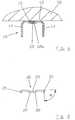
- FIG. 2shows an exemplary embodiment of a connecting element 20 according to the invention.
- Thisis designed as a generally elongated sheet-metal part and has two end-side projections 21 and two central projections 22.
- the two central projections 22are connected to each other via a notch or "bead".
- the end projections 21may be formed perpendicular to the main plane of the connecting element, which is parallel to the plane of the wall or the back part 12 of the wall rail 10, or preferably an angle ⁇ relative to this main plane of between 60 ° and 85 °, preferably between 75 ° and 85 respectively.
- the connecting element 20formed of an elastic material such as steel sheet may have a exert elastic attractive force on the two wall rails to be connected
- Figure 3shows two end abutting wall rails 10 according to an embodiment of the present invention in front view, d. H. in the direction of the wall and Figure 4 two interconnected by a connecting element 20 wall rails 10 in rear view.
- the wall rails 10have in their rear side portion in each case a forwardly projecting central portion 12a, which forms a cavity 15 on its (wall-side) rear side.
- the connecting element 20is received for connection of two end abutting wall rails 10, as shown in Figures 1, 4 and 5.
- holes 18may be provided for fixing the wall rail to the wall
- two openings 17, 19are also formed near the longitudinal end of the wall rail 12.
- the first opening 17is formed as a transversely formed slot
- the second opening 19is formed rectangularly at the end of the central portion 12a connect the end-side projections 21 of the connecting element 20 in the transverse slots 17 and thus cause a fixation of the wall rails to each other in the longitudinal direction (see also Figure 5).
- the central projections 22 of the connecting element 20engage in the two adjacent openings 19 and cause a fixation of the two rails to each other in the transverse direction.
- the positionally precise engagement of the elongate connecting element 20 at a total of four locationsalso causes a parallel alignment of the two U-shaped wall rails 10 to each other
- the inventionthus provides a wall rail system with a wall rail and a connecting element, which allows a secure connection, fixation and alignment of the rails to each other, without interfering with the work space between the side legs and the back of the U-profile.
- the inventionthus provides a very lightweight, compact and easy mounting enabling fastening solution.
Landscapes
- Engineering & Computer Science (AREA)
- General Engineering & Computer Science (AREA)
- Mechanical Engineering (AREA)
- Finishing Walls (AREA)
- Cabinets, Racks, Or The Like Of Rigid Construction (AREA)
- Hooks, Suction Cups, And Attachment By Adhesive Means (AREA)
- Body Structure For Vehicles (AREA)
- Supports Or Holders For Household Use (AREA)
- Connection Of Plates (AREA)
- Display Racks (AREA)
- Tires In General (AREA)
Abstract
Description
Translated fromGermanDie Erfindung betrifft ein Wandschienensystem zum Einhängen von Regalbodenträgern oder dergleichen, um ein flexibles, vielseitig einsetzbares Regalsystem zu bildenThe invention relates to a wall rail system for suspending shelf supports or the like to form a flexible, versatile shelving system
Derartige bekannte Regalsysteme werden vielfältig genutzt und haben sich im privaten und gewerblichen Einsatz bspw, für die großflächige Ablage von Büchern, Waren, Akten und dergleichen bewährt Da solche Regalsysteme nach oben und zur Seite beliebig erweitert werden können, weisen sie eine große Flexibilität aufSuch known shelving systems are widely used and have proven in private and commercial use, for example, for large-scale storage of books, goods, files and the like Since such shelving systems can be expanded upwards and to the side, they have a great deal of flexibility
In manchen Fällen, insbesondere bei gewerblichen Anwendungen sind durchaus Regalhöhen von drei Metern, vier Metern oder mehr üblich Aus Transport-, Lagerund Handhabungsgründen sind jedoch Wandschienen von mehr als 1,5 bis 2 Meter Länge unpraktisch und ungebräuchlich Es ist daher notwendig, zwei oder mehrere Wandschienen übereinander anzubringen Es besteht daher ein Bedarf an Befestigungsmitteln, zwei in Längsrichtung aneinander stoßende Wandschienen zueinander auszurichten und miteinander zu befestigenIn some cases, especially in commercial applications shelf heights of three meters, four meters or more are quite common For transport, storage and handling reasons, however, wall rails of more than 1.5 to 2 meters in length are impractical and uncommon It is therefore necessary two or more There is therefore a need for fastening means to align two mutually longitudinally abutting wall rails to each other and to secure together
Ein verbreiteter Typ von vertikalen Wandschienen sind sogenannte U-Profilschienen, bei denen ein mit der Wand paralleles Rückenteil an der Wand befestigt wird, von welchem Rückenteil zwei seitliche Schenkel nach vorne vorstehen. Die Schenkel können Löcher, Öffnungen oder dergleichen zum Einhängen von Regalbodenträgern oder Ähnlichem oder vertikale Einkerbungen zum Führen von beweglichen Halteelementen oder Ähnlichem aufweisen, Um die Nutzung der U-Profilschiene nicht einzuschränken, sollte der zwischen Rückenteil und Seitenschenkeln gebildete Raum möglichst wenig eingeschränkt werden.A common type of vertical wall rails are so-called U-profile rails, in which a parallel to the wall back part is fixed to the wall, projecting from which back two lateral legs forward. The legs may have holes, openings or the like for suspending shelf supports or the like or vertical indentations for guiding movable holding elements or the like. In order not to restrict the use of the U-profile rail, the space formed between the back part and side legs should be restricted as little as possible.
Der vorliegenden Erfindung liegt daher die Aufgabe zugrunde, ein Wandschienensystem mit wenigstens einer Wandschiene und einem Verbindungselement vorzuschlagen, welches eine sichere Fixierung zweier in Längsrichtung aneinanderstoßender U-Profil-förmiger Wandschienen sowie eine Ausrichtung der Wandschienen zueinander erlaubt, ohne dass der zwischen den Seitenschenkeln und dem Rückenteil des U-Profils gebildete Nutzraum wesentlich eingeschränkt wird.The present invention is therefore the object of providing a wall rail system with at least one wall rail and a connecting element, which allows secure fixation of two abutting U-shaped rail rails in the longitudinal direction and alignment of the wall rails to each other, without that between the side legs and the Back part of the U-shaped utility space formed is significantly limited.
Zur Lösung dieser Aufgabe wird erfindungsgemäß ein Wandschienensystem vorgeschlagen aufweisend wenigstens eine als U-förmiges Profil ausgebildete Wandschiene mit einem an einer Wand befestigbaren Rückenteil und zwei von der Wand abgewandten Seitenschenkeln sowie einem an der der Wand zugewandten Seite des Rückenteils sich in Längsrichtung erstreckenden rückseitigen Hohlraum und einem Verbindungselement zur Verbindung zweier in Längsrichtung aneinanderstoßender Wandschienen, welches Verbindungselement in einem verbundenen Zustand der Wandschienen in dem rückseitigen Hohlraum aufgenommen istTo solve this problem, a wall rail system is proposed according to the invention comprising at least one trained as a U-shaped profile rail with a wall fastened back part and two side facing away from the wall side legs and on the wall-facing side of the back in the longitudinal direction extending rear cavity and a connecting element for connecting two longitudinally abutting wall rails, which connecting element is received in a connected state of the wall rails in the rear cavity
Das Verbindungselement fixiert so die beiden an ihren Endseiten aneinanderstoßenden Wandschienen Da es jedoch in dem zur Wandseite ausgebildeten Hohlraum hinter dem Rückenteil der Wandschiene aufgenommen ist, ragt das Verbindungsteil nicht in den Nutzraum hinein, der zwischen den beiden Seitenschenkeln und der Rückwand der U-Profil-förmigen Wandschiene gebildet wird. Das Verbindungselement beeinträchtigt daher nicht die Befestigung oder vertikale Bewegung von Halteelementen oder dergleichen, Die Wandschiene kann so äußerst kompakt ausgebildet sein.The connecting element thus fixes the two abutting wall rails at their end sides. However, since it is accommodated in the cavity formed to the wall side behind the rear part of the wall rail, the connecting part does not protrude into the working space which is located between the two side legs and the rear wall of the U-profile. shaped wall rail is formed. Therefore, the connecting element does not interfere with the attachment or vertical movement of holding elements or the like. The wall rail can thus be made extremely compact.
Gemäß einem bevorzugten Ausführungsbeispiel weist die Wandschiene an wenigstens einem längsseitigen Ende erste und zweite Öffnungen und das Verbindungselement beidseitig erste und zweite Vorsprünge zum Eingriff in die in der Wandschiene ausgebildeten Öffnungen auf Durch den Eingriff der Vorsprünge des Verbindungselements in die jeweiligen Öffnungen der Wandschienen werden diese miteinander verbunden und aneinander fixiert.According to a preferred embodiment, the wall rail has at least one longitudinal end first and second openings and the connecting element on both sides of first and second projections for engaging in the Through the engagement of the projections of the connecting element in the respective openings of the wall rails they are connected to each other and fixed to each other.
Die erste Öffnung kann vorzugsweise als quer zur Längsrichtung der Wandschiene ausgeformter Schlitz und die ersten Vorsprünge endseitig des Verbindungselements zum Eingriff in die quer ausgebildeten Schlitze aneinanderstoßender Wandschienen ausgebildet sein, wodurch eine relative Positionsfixierung der Wandschienen in Längsrichtung bewirkt wird.The first opening may preferably be formed as a slot formed transversely to the longitudinal direction of the wall rail and the first projections on the end of the connecting element for engagement with the transverse slots of abutting wall rails, thereby effecting relative positional fixing of the wall rails longitudinally.
Weiterhin kann vorzugsweise die zweite Öffnung als eine endseitig der Wandschiene ausgeformte, im Wesentlichen rechteckförmige Ausnehmung und die zweiten Vorsprünge des Verbindungselements mittig zum Eingriff in diese zweiten Öffnungen ausgebildet sein, wodurch eine Positionierung der Wandschienen zueinander in Querrichtung bewirkt wirdFurthermore, preferably, the second opening may be formed as a substantially rectangular recess formed at the end of the wall rail and the second protrusions of the connecting element may be formed centrally for engagement in these second openings, whereby a transverse positioning of the wall rails is effected
Durch die Kombination von schlitzförmiger Ausnehmung zur Positionierung in Längsrichtung und rechteckförmiger Ausnehmung zur Positionierung in Querrichtung kann mit einem platzsparenden, leichten und sehr preiswert herzustellenden Verbindungselement eine sichere Positionsfixierung sowohl in Längsrichtung als auch in Querrichtung und auch eine Ausrichtung der Schienen zueinander erreicht werdenThe combination of slot-shaped recess for positioning in the longitudinal direction and rectangular recess for positioning in the transverse direction can be achieved with a space-saving, lightweight and very inexpensive to produce connecting element secure position fixation both longitudinally and transversely and also an alignment of the rails to each other
Das Verbindungselement kann vorzugsweise als längliches, flaches Metallelement mit den beidseitigen ersten und zweiten Vorsprüngen ausgebildet sein Dieses ist leicht, klein und kostengünstig herzustellen,The connecting element may preferably be formed as an elongated, flat metal element with the two-sided first and second projections. This is easy, small and inexpensive to manufacture,
Die endseitigen ersten Vorsprünge des Verbindungselements können dabei einen Winkel von zwischen 60° und 85°, vorzugsweise zwischen 75° und 850° gegenüber der Grundebene des Verbindungselements aufweisen, welche Grundebene parallel zur Wand und zur Ebene des Rückenteils der U-Profilschiene ist. Diese Anwinkelung erleichtert die Montage und Fixierung zweier Wandschienen miteinander und bewirkt eine elastische Kraft, die die beiden Schienen miteinander verbindetThe end-side first projections of the connecting element can have an angle of between 60 ° and 85 °, preferably between 75 ° and 850 ° relative to the ground plane of the connecting element, which ground plane is parallel to the wall and the back of the U-profile rail. This angling facilitates the assembly and fixation of two wall rails together and causes an elastic force that connects the two rails together
Gemäß einem bevorzugten Ausführungsbeispiel sind die beiden mittigen Vorsprünge des Verbindungselements durch eine kleine Einkerbung oder "Sicke" miteinander verbunden, die die Stabilität des Verbindungselements erhöht.According to a preferred embodiment, the two central projections of the connecting element are interconnected by a small notch or "bead" which increases the stability of the connecting element.
Die Erfindung wird im Folgenden anhand eines konkreten Ausführungsbeispiels unter Bezugnahme auf die beiliegenden Zeichnungen erläutert
- Figur 1 zeigt ein Ausführungsbeispiel des erfindungsgemäßen Wandschienensystems in Horizontalschnittansicht
- Figur 2 zeigt ein Ausführungsbeispiel des erfindungsgemäßen Verbindungselements in Seitenansicht
- Figur 3 ist eine Ansicht von vorne, die zwei endseitig aneinanderstoßende Wandschienen gemäß einem Ausführungsbeispiel der Erfindung zeigt.
- Figur 4 ist eine Rückseitenansicht zweier mittels Verbindungselement miteinander verbundener Wandschienen.
- Figur 5 ist eine Vertikalschnittansicht eines Ausführungsbeispiels des erfindungsgemäßen Wandschienensystems
- Figure 1 shows an embodiment of the wall rail system according to the invention in horizontal section view
- Figure 2 shows an embodiment of the connecting element according to the invention in side view
- Figure 3 is a front view showing two end abutting wall rails according to one embodiment of the invention.
- Figure 4 is a rear view of two interconnected by means of connecting element wall rails.
- FIG. 5 is a vertical sectional view of an embodiment of the wall rail system according to the invention
Die Erfindung wird im Folgenden anhand von konkreten Ausführungsbeispielen im Detail erläutert.The invention will be explained below with reference to specific embodiments in detail.
Figur 1 zeigt in Horizontalschnittansicht ein Ausführungsbeispiel des erfindungsgemäßen Wandschienensystems Dieses besteht aus einer U-Profil-förmigen Wandschiene 10 sowie einem Verbindungselement 20 zum Verbinden zweier an ihren längsseitigen Enden zusammenstoßender Wandschienen (Figuren 3-5), um so zwei oder mehrere Wandschienen übereinander an einer Wand, Stellwand, einem Gestell oder dergleichen anbringen zu können Die Wandschiene ist insgesamt als U-förmiges Profil mit einem an einer Wand 50 fixierbaren Rückenteil 12 sowie zwei von der Wand abstehenden Seitenschenkeln 14 ausgebildet An den vorderen, der Wand abgewandten Enden der Seitenschenkel 14 können Nuten, vorragende Abschlusselemente oder Schienen oder dergleichen zur Aufnahme von Gleitelementen oder horizontal verschiebbaren Tragelementen ausgebildet sein Die Form und Ausbildung der Seitenschenkel 14 spielt für die vorliegende Erfindung keine Rolle.This consists of a U-shaped
Das an der Wand bspw mittels Schrauben befestigbare Rückenteil 12 der Wandschiene 10 weist einen nach vorne (d. h von der Wand weg) vorspringenden Abschnitt 12a auf, der auf der Wandseite einen Hohlraum 15 bildet. In diesem Hohlraum 15 ist das Verbindungselement 20 zur Verbindung zweier senkrecht aneinanderstoßender Profilschienen 10 aufgenommenThe
Figur 2 zeigt ein Ausführungsbeispiel eines erfindungsgemäßen Verbindungselements 20. Dieses ist als ein insgesamt längliches Blechteil ausgebildet und weist zwei endseitige Vorsprünge 21 sowie zwei mittige Vorsprünge 22 auf. Die beiden mittigen Vorsprünge 22 sind über eine Kerbe oder "Sicke" miteinander verbunden. Eine andere Form der ittleren Vorsprünge ist jedoch ebenfalls möglich. Die endseitigen Vorsprünge 21 können senkrecht zur Hauptebene des Verbindungselements, die parallel zur Ebene der Wand bzw des Rückenteils 12 der Wandschiene 10 ist, ausgebildet sein oder vorzugsweise einen Winkel α gegenüber dieser Hauptebene von zwischen 60° und 85°, vorzugsweise zwischen 75° und 85° aufweisen. Durch diese Winkelstellung wird die Montage des Verbindungselements sowie der Wandschienen erleichtert. Außerdem kann das aus einem elastischen Material wie Stahlblech ausgebildete Verbindungselement 20 eine elastische anziehende Kraft auf die beiden zu verbindenden Wandschienen ausübenFIG. 2 shows an exemplary embodiment of a connecting
Figur 3 zeigt zwei endseitig aneinanderstoßende Wandschienen 10 gemäß einem Ausführungsbeispiel der vorliegenden Erfindung in Ansicht von vorne, d. h. in Blickrichtung auf die Wand hin und Figur 4 zwei durch ein Verbindungselement 20 miteinander verbundene Wandschienen 10 in Ansicht von hinten.Figure 3 shows two end abutting
Die Wandschienen 10 weisen in ihrem Rückseitenabschnitt jeweils einen nach vorne vorspringenden Mittelabschnitt 12a auf, der auf seiner (wandseitigen) Rückseite einen Hohlraum 15 bildet. In diesem Hohlraum 15 ist das Verbindungselement 20 zur Verbindung zweier endseitig aneinanderstoßender Wandschienen 10 aufgenommen, wie in Figuren 1, 4 und 5 gezeigt ist. Im Mittelabschnitt 12 a der Wandschiene 10 können Löcher 18 zur Fixierung der Wandschiene an der Wand vorgesehen seinThe
In dem nach vorne vorstehenden Mittelabsctrnitt 12a sind außerdem nahe dem längsseitigen Ende der Wandschiene 12 zwei Öffnungen 17, 19 ausgeformt Die erste Öffnung 17 ist als in Querrichtung ausgeformter Schlitz ausgebildet, während die zweite Öffnung 19 rechteckförmig am Ende des Mittelabschnitts 12a ausgebildet ist Um zwei Wandschienen miteinander zu verbinden greifen die endseitigen Vorsprünge 21 des Verbindungselements 20 in die Querschlitze 17 ein und bewirken so eine Fixierung der Wandschienen zueinander in Längsrichtung (siehe auch Figur 5). Die mittigen Vorsprünge 22 des Verbindungselements 20 greifen in die beiden aneinanderliegenden Öffnungen 19 ein und bewirken eine Fixierung der beiden Schienen zueinander in Querrichtung. Der positionsgenaue Eingriff des länglichen Verbindungselements 20 an insgesamt vier Stellen bewirkt außerdem eine parallele Ausrichtung der beiden U-förmigen Wandschienen 10 zueinanderIn the forward projecting
Der Fachmann erkennt, dass die exakte Form des Verbindungselements 20 mit den Vorsprüngen 21, 22 sowie die genaue Form und Position der Öffnungen 17, 19 in der Wandschiene 10 im Rahmen der vorliegenden Erfindung variieren kannIt will be appreciated by those skilled in the art that the exact shape of the
Die Erfindung liefert somit ein Wandschienensystem mit einer Wandschiene sowie einem Verbindungselement, welches eine sichere Verbindung, Fixierung und Ausrichtung der Schienen zueinander ermöglicht, ohne in den Nutzraum zwischen den Seitenschenkeln und der Rückseite des U-Profils einzugreifen. Die Erfindung liefert damit eine sehr leichte, kompakte und eine einfache Montage ermöglichende Befestigungslösung.The invention thus provides a wall rail system with a wall rail and a connecting element, which allows a secure connection, fixation and alignment of the rails to each other, without interfering with the work space between the side legs and the back of the U-profile. The invention thus provides a very lightweight, compact and easy mounting enabling fastening solution.
Claims (8)
Translated fromGermanPriority Applications (9)
| Application Number | Priority Date | Filing Date | Title |
|---|---|---|---|
| EP06110619AEP1830074A1 (en) | 2006-03-03 | 2006-03-03 | Wall rail system |
| CNA2007800074836ACN101395389A (en) | 2006-03-03 | 2007-02-16 | Wall rail system |
| RU2008135278/11ARU2416349C2 (en) | 2006-03-03 | 2007-02-16 | System of wall braces |
| UAA200811709AUA91272C2 (en) | 2006-03-03 | 2007-02-16 | Wall rail system |
| PCT/EP2007/051492WO2007101773A2 (en) | 2006-03-03 | 2007-02-16 | Wall rail system |
| US12/281,466US20090050592A1 (en) | 2006-03-03 | 2007-02-16 | Wall rail system |
| MX2008011199AMX2008011199A (en) | 2006-03-03 | 2007-02-16 | Wall rail system. |
| JP2008556745AJP2009528462A (en) | 2006-03-03 | 2007-02-16 | Wall rail system |
| US13/043,359US20110155678A1 (en) | 2006-03-03 | 2011-03-08 | Wall rail system |
Applications Claiming Priority (1)
| Application Number | Priority Date | Filing Date | Title |
|---|---|---|---|
| EP06110619AEP1830074A1 (en) | 2006-03-03 | 2006-03-03 | Wall rail system |
Publications (1)
| Publication Number | Publication Date |
|---|---|
| EP1830074A1true EP1830074A1 (en) | 2007-09-05 |
Family
ID=36834280
Family Applications (1)
| Application Number | Title | Priority Date | Filing Date |
|---|---|---|---|
| EP06110619AWithdrawnEP1830074A1 (en) | 2006-03-03 | 2006-03-03 | Wall rail system |
Country Status (8)
| Country | Link |
|---|---|
| US (2) | US20090050592A1 (en) |
| EP (1) | EP1830074A1 (en) |
| JP (1) | JP2009528462A (en) |
| CN (1) | CN101395389A (en) |
| MX (1) | MX2008011199A (en) |
| RU (1) | RU2416349C2 (en) |
| UA (1) | UA91272C2 (en) |
| WO (1) | WO2007101773A2 (en) |
Families Citing this family (6)
| Publication number | Priority date | Publication date | Assignee | Title |
|---|---|---|---|---|
| ATE387872T1 (en)* | 2005-12-21 | 2008-03-15 | Element System Rudolf Bohnacke | SHELF SYSTEM WITH A CONTINUOUSLY MOVEABLE SUPPORT ELEMENT IN A WALL RAIL |
| EP1829463A1 (en)* | 2006-03-03 | 2007-09-05 | Element -System Rudolf Bohnacker GmbH | Shelf support provided with spacer elements |
| DE102011115319A1 (en)* | 2011-10-07 | 2013-04-11 | Liebherr-Transportation Systems GmbH & Co.KG | Connecting element for a supporting frame system |
| KR200470181Y1 (en)* | 2012-03-27 | 2013-12-03 | 대우조선해양 주식회사 | A buried type handrail device for ship |
| JP7519077B2 (en)* | 2020-06-11 | 2024-07-19 | 株式会社藤山 | Wall-mounted shelf column |
| WO2022167711A1 (en)* | 2021-02-02 | 2022-08-11 | Kone Corporation | Guide rail part, connecting part and spring element for an elevator and method for assembling guide rail |
Citations (6)
| Publication number | Priority date | Publication date | Assignee | Title |
|---|---|---|---|---|
| US3480155A (en)* | 1968-04-24 | 1969-11-25 | Hirsh | Steel shelving |
| DE2109117A1 (en)* | 1971-02-26 | 1972-09-07 | Pfannenberg Gmbh | Connection of butt abutting hollow profile rods |
| DE7605588U1 (en)* | 1976-01-15 | 1976-10-21 | Gregorovic, Dragutin, Luettich (Belgien) | SUPPORTING FRAME FOR CONSTRUCTION OF SHELVES AND CEILINGS AND FOR HANGING RADIATORS AND THE LIKE |
| GB1503214A (en)* | 1974-03-08 | 1978-03-08 | Bohnacker R | Support arrangement for shelves |
| EP0095021A1 (en)* | 1982-05-21 | 1983-11-30 | Richter-System GmbH & Co. KG | Panel connector |
| US6089387A (en)* | 1997-09-18 | 2000-07-18 | Varfolomeeva; Elena P. | Display equipment |
Family Cites Families (48)
| Publication number | Priority date | Publication date | Assignee | Title |
|---|---|---|---|---|
| CH282233A (en)* | 1949-06-07 | 1952-04-15 | Felix Andre | Rack support. |
| US2636618A (en)* | 1950-08-30 | 1953-04-28 | James L Merrick | Knockdown shelving and the like |
| US3429540A (en)* | 1966-05-30 | 1969-02-25 | Worrallo A C | Self-locking bracket and the like |
| GB1291258A (en)* | 1969-02-21 | 1972-10-04 | Nexus Ltd | Shelving structure |
| US3574980A (en)* | 1969-05-05 | 1971-04-13 | Woodcarve Products Inc | Shelf bracket for panelled walls |
| US3604670A (en)* | 1970-05-20 | 1971-09-14 | Fmp Fabricating Ltd | Shelf bracket adaptor |
| US3730468A (en)* | 1971-12-20 | 1973-05-01 | Gypsum Co | Furniture supporting system |
| GB1517532A (en)* | 1976-05-28 | 1978-07-12 | M Grosse | Support systems for articles of furniture |
| US4103855A (en)* | 1976-07-01 | 1978-08-01 | Maurice Grosse | Support systems for articles of furniture |
| IL50351A (en)* | 1976-08-24 | 1979-01-31 | Mochly J | Wall bracket and its support |
| US4274614A (en)* | 1978-05-24 | 1981-06-23 | Worrallo A C | Locking device and the like |
| US4223863A (en)* | 1978-09-28 | 1980-09-23 | Josef Birman | Shelf supports |
| US4299368A (en)* | 1979-03-19 | 1981-11-10 | Winkler Clifford W | Infinitely adjustable bracket-standard mounting |
| US4305677A (en)* | 1979-10-04 | 1981-12-15 | B-Line Systems, Inc. | Connector |
| US4389828A (en)* | 1980-06-12 | 1983-06-28 | Howmet Aluminum Corp. | Suspended ceiling system with crossing clip |
| DE3042537A1 (en)* | 1980-11-12 | 1982-06-24 | Gewerkschaft Eisenhütte Westfalia, 4670 Lünen | DISTANCE PIECE FOR SECURING THE TOGGLE CONNECTION OF GUTTER SHOTS OF A CHAIN SCRATCH CONVEYOR OR GUIDE SHOTS OF A WINNING MACHINE GUIDE AND THE LIKE. |
| US4421289A (en)* | 1982-02-22 | 1983-12-20 | Sp Industries, Inc. | Shelf support |
| US4537379A (en)* | 1982-03-25 | 1985-08-27 | Rhoades Reginald L | Shelving means |
| US4516874A (en)* | 1984-04-23 | 1985-05-14 | The Firestone Tire & Rubber Company | Channel Connector |
| NZ210863A (en)* | 1985-01-17 | 1988-03-30 | Onteam Ltd | Wall frame: interconnected metal studs and plates |
| US4674723A (en)* | 1985-07-08 | 1987-06-23 | Robert Bayuk | Adjustable shelf assembly |
| ES288009Y (en)* | 1985-07-11 | 1986-06-16 | Bohigas Gurgui Merce | ADJUSTABLE SUPPORT FOR RACKS |
| US4850172A (en)* | 1986-04-25 | 1989-07-25 | Alcan Aluminum Corporation | Ceiling or like structural system and splice member therefor |
| US4787625A (en)* | 1986-07-24 | 1988-11-29 | Chaloux John A | Karate board holding devices |
| US4738426A (en)* | 1987-03-23 | 1988-04-19 | Knape & Vogt Manufacturing Company | Resilient sleeve glass shelf bracket |
| US4891887A (en)* | 1988-06-30 | 1990-01-09 | Karl Witte | Hand held drill drive |
| US4934642A (en)* | 1989-03-29 | 1990-06-19 | Australian Slatwall Industries Pty Ltd. | Shelf-support bracket |
| WO1992009222A1 (en)* | 1990-11-26 | 1992-06-11 | Britannia Shelving Limited | A shelf support system |
| GB9105942D0 (en)* | 1991-03-20 | 1991-05-08 | Stakapal Ltd | Improvements relating to racking |
| US5253835A (en)* | 1992-02-18 | 1993-10-19 | Herron Iii Warren L | Shelf bracket assembly |
| US5388796A (en)* | 1992-08-12 | 1995-02-14 | Phoenix Display Corporation | Standard and bracket support system |
| US5318264A (en)* | 1992-11-12 | 1994-06-07 | National Manufacturing Co. | Infinitely adjustable shelving and method |
| EP0700650A3 (en)* | 1994-09-09 | 1997-10-01 | Glaeser Ag | Bracket for wall attachment of shelves of different thickness |
| GB9503803D0 (en)* | 1995-02-24 | 1995-04-12 | Chainport Ltd | Shelf holder |
| AUPO200296A0 (en)* | 1996-08-30 | 1996-09-19 | Bhp Steel (Jla) Pty Limited | Wall stud connectors |
| US6047838A (en)* | 1997-03-14 | 2000-04-11 | Kewaunee Scientific Corp. | Modular support post |
| US6272803B1 (en)* | 1999-01-28 | 2001-08-14 | Steelcase Development Corporation | Connector system for in-line connection of freestanding partitions |
| US6196141B1 (en)* | 1999-02-22 | 2001-03-06 | Herron, Iii Warren L. | Vertically stabilized adjustable shelf bracket assembly |
| RU14620U1 (en)* | 2000-03-06 | 2000-08-10 | Мироненко Михаил Тихонович | ASSEMBLY ASSEMBLY ASSEMBLY |
| US6364263B1 (en)* | 2000-06-06 | 2002-04-02 | James A. Ryan | Fixture support system |
| US6412739B1 (en)* | 2000-09-01 | 2002-07-02 | Joel A. Smith | Shelf anti-sagging support brace |
| US6684929B2 (en)* | 2002-02-15 | 2004-02-03 | Steelcase Development Corporation | Panel system |
| US7296697B2 (en)* | 2002-12-18 | 2007-11-20 | Rubbermaid Incorporated | Adjustable closet organizer system |
| US7240803B2 (en)* | 2002-12-18 | 2007-07-10 | Rubbermaid, Inc. | Shelf mounting bracket for adjustable organizer system |
| US7243887B2 (en)* | 2003-08-18 | 2007-07-17 | Elfa International Ab | Suspension system |
| US20050224428A1 (en)* | 2004-04-09 | 2005-10-13 | Leo Weber | Show case, in particular for displaying shoes or the like |
| ATE387872T1 (en)* | 2005-12-21 | 2008-03-15 | Element System Rudolf Bohnacke | SHELF SYSTEM WITH A CONTINUOUSLY MOVEABLE SUPPORT ELEMENT IN A WALL RAIL |
| EP1829463A1 (en)* | 2006-03-03 | 2007-09-05 | Element -System Rudolf Bohnacker GmbH | Shelf support provided with spacer elements |
- 2006
- 2006-03-03EPEP06110619Apatent/EP1830074A1/ennot_activeWithdrawn
- 2007
- 2007-02-16MXMX2008011199Apatent/MX2008011199A/ennot_activeApplication Discontinuation
- 2007-02-16CNCNA2007800074836Apatent/CN101395389A/enactivePending
- 2007-02-16WOPCT/EP2007/051492patent/WO2007101773A2/enactiveApplication Filing
- 2007-02-16USUS12/281,466patent/US20090050592A1/ennot_activeAbandoned
- 2007-02-16UAUAA200811709Apatent/UA91272C2/enunknown
- 2007-02-16RURU2008135278/11Apatent/RU2416349C2/ennot_activeIP Right Cessation
- 2007-02-16JPJP2008556745Apatent/JP2009528462A/enactivePending
- 2011
- 2011-03-08USUS13/043,359patent/US20110155678A1/ennot_activeAbandoned
Patent Citations (6)
| Publication number | Priority date | Publication date | Assignee | Title |
|---|---|---|---|---|
| US3480155A (en)* | 1968-04-24 | 1969-11-25 | Hirsh | Steel shelving |
| DE2109117A1 (en)* | 1971-02-26 | 1972-09-07 | Pfannenberg Gmbh | Connection of butt abutting hollow profile rods |
| GB1503214A (en)* | 1974-03-08 | 1978-03-08 | Bohnacker R | Support arrangement for shelves |
| DE7605588U1 (en)* | 1976-01-15 | 1976-10-21 | Gregorovic, Dragutin, Luettich (Belgien) | SUPPORTING FRAME FOR CONSTRUCTION OF SHELVES AND CEILINGS AND FOR HANGING RADIATORS AND THE LIKE |
| EP0095021A1 (en)* | 1982-05-21 | 1983-11-30 | Richter-System GmbH & Co. KG | Panel connector |
| US6089387A (en)* | 1997-09-18 | 2000-07-18 | Varfolomeeva; Elena P. | Display equipment |
Also Published As
| Publication number | Publication date |
|---|---|
| JP2009528462A (en) | 2009-08-06 |
| WO2007101773A3 (en) | 2007-11-01 |
| CN101395389A (en) | 2009-03-25 |
| US20090050592A1 (en) | 2009-02-26 |
| US20110155678A1 (en) | 2011-06-30 |
| WO2007101773A2 (en) | 2007-09-13 |
| UA91272C2 (en) | 2010-07-12 |
| RU2008135278A (en) | 2010-04-10 |
| RU2416349C2 (en) | 2011-04-20 |
| MX2008011199A (en) | 2009-01-27 |
Similar Documents
| Publication | Publication Date | Title |
|---|---|---|
| DE3021245A1 (en) | DISPLAY | |
| EP1830074A1 (en) | Wall rail system | |
| DE2610998C3 (en) | Bracket for fastening cladding panels in front of a building wall | |
| DE29814432U1 (en) | Partition arrangement | |
| EP0404726A2 (en) | Device for connecting c-shaped rails, especially mounting rails | |
| DE102013225173A1 (en) | Mounting profile for plate-shaped modules | |
| DE2326948A1 (en) | PANEL SYSTEM CONSTRUCTION | |
| EP2440721A1 (en) | Wall covering | |
| DE2923903A1 (en) | Wall mounted radiator securing structure - includes vertical channel with slots in sides and retaining lugs for horizontal arms | |
| EP2862984B1 (en) | Sectional structure for glazing a building | |
| DE29509555U1 (en) | Control cabinet with mounting plate as a single or modular cabinet | |
| EP0158016B1 (en) | Cupboard | |
| DE817191C (en) | Frame molding | |
| DE3411619A1 (en) | FASTENING UNIT FOR FASTENING PANELS AND ASSEMBLED ASSEMBLY OF THE FASTENING UNITS | |
| DE202007001060U1 (en) | Modular shelving system, comprises covers to be clipped to outer side of holding elements | |
| WO2006092156A1 (en) | Wall element | |
| DE202013100898U1 (en) | Construction unit, in particular for furniture | |
| DE20103586U1 (en) | Drawer holder | |
| CH658092A5 (en) | KIT FOR CREATING A HANGABLE GRID CEILING. | |
| DE29823221U1 (en) | Wall bracket for cladding panels, especially facade elements | |
| DE202019104735U1 (en) | towel rail | |
| EP1295546B1 (en) | Coupling elements for the connection of shelves on storage racks | |
| DE29707568U1 (en) | Pull-out for furniture or the like, especially for office furniture | |
| DE2263899A1 (en) | SURFACE COVERING | |
| DE29800498U1 (en) | Device for fastening panel-like ceiling or wall elements |
Legal Events
| Date | Code | Title | Description |
|---|---|---|---|
| PUAI | Public reference made under article 153(3) epc to a published international application that has entered the european phase | Free format text:ORIGINAL CODE: 0009012 | |
| 17P | Request for examination filed | Effective date:20070126 | |
| AK | Designated contracting states | Kind code of ref document:A1 Designated state(s):AT BE BG CH CY CZ DE DK EE ES FI FR GB GR HU IE IS IT LI LT LU LV MC NL PL PT RO SE SI SK TR | |
| AX | Request for extension of the european patent | Extension state:AL BA HR MK YU | |
| AKX | Designation fees paid | Designated state(s):AT BE BG CH CY CZ DE DK EE ES FI FR GB GR HU IE IS IT LI LT LU LV MC NL PL PT RO SE SI SK TR | |
| 19U | Interruption of proceedings before grant | Effective date:20101220 | |
| 19W | Proceedings resumed before grant after interruption of proceedings | Effective date:20120702 | |
| RAP1 | Party data changed (applicant data changed or rights of an application transferred) | Owner name:RUDOLF BOHNACKER SYSTEME GMBH | |
| STAA | Information on the status of an ep patent application or granted ep patent | Free format text:STATUS: THE APPLICATION IS DEEMED TO BE WITHDRAWN | |
| 18D | Application deemed to be withdrawn | Effective date:20130103 |