EP1827908B1 - An accessory module system for a vehicle window - Google Patents
An accessory module system for a vehicle windowDownload PDFInfo
- Publication number
- EP1827908B1 EP1827908B1EP20050850274EP05850274AEP1827908B1EP 1827908 B1EP1827908 B1EP 1827908B1EP 20050850274EP20050850274EP 20050850274EP 05850274 AEP05850274 AEP 05850274AEP 1827908 B1EP1827908 B1EP 1827908B1
- Authority
- EP
- European Patent Office
- Prior art keywords
- assembly
- accessory module
- accessory
- module system
- vehicle
- Prior art date
- Legal status (The legal status is an assumption and is not a legal conclusion. Google has not performed a legal analysis and makes no representation as to the accuracy of the status listed.)
- Not-in-force
Links
- 238000004891communicationMethods0.000claimsdescription10
- 239000000463materialSubstances0.000claimsdescription9
- 239000000853adhesiveSubstances0.000claimsdescription6
- 230000001070adhesive effectEffects0.000claimsdescription6
- 230000004438eyesightEffects0.000claimsdescription5
- 238000009423ventilationMethods0.000claims3
- 238000001816coolingMethods0.000claims1
- 230000006870functionEffects0.000description11
- 238000003384imaging methodMethods0.000description8
- 238000001514detection methodMethods0.000description5
- 238000005286illuminationMethods0.000description5
- 230000007613environmental effectEffects0.000description4
- 238000004519manufacturing processMethods0.000description4
- 230000003213activating effectEffects0.000description3
- 239000000356contaminantSubstances0.000description3
- 239000000428dustSubstances0.000description3
- 239000012530fluidSubstances0.000description3
- 230000004313glareEffects0.000description3
- 239000012528membraneSubstances0.000description3
- 229910052751metalInorganic materials0.000description3
- 239000002184metalSubstances0.000description3
- 230000002411adverseEffects0.000description2
- 238000004378air conditioningMethods0.000description2
- 230000000712assemblyEffects0.000description2
- 238000000429assemblyMethods0.000description2
- 238000010276constructionMethods0.000description2
- 238000002955isolationMethods0.000description2
- 238000000034methodMethods0.000description2
- 238000012544monitoring processMethods0.000description2
- 230000005855radiationEffects0.000description2
- UGFAIRIUMAVXCW-UHFFFAOYSA-NCarbon monoxideChemical compound[O+]#[C-]UGFAIRIUMAVXCW-UHFFFAOYSA-N0.000description1
- 229920000544Gore-TexPolymers0.000description1
- 230000005355Hall effectEffects0.000description1
- 206010041349SomnolenceDiseases0.000description1
- 238000009825accumulationMethods0.000description1
- 239000000956alloySubstances0.000description1
- 229910045601alloyInorganic materials0.000description1
- 239000004411aluminiumSubstances0.000description1
- 229910052782aluminiumInorganic materials0.000description1
- XAGFODPZIPBFFR-UHFFFAOYSA-NaluminiumChemical compound[Al]XAGFODPZIPBFFR-UHFFFAOYSA-N0.000description1
- 230000004888barrier functionEffects0.000description1
- 230000008901benefitEffects0.000description1
- 230000005540biological transmissionEffects0.000description1
- 230000015572biosynthetic processEffects0.000description1
- 229910002091carbon monoxideInorganic materials0.000description1
- 230000001413cellular effectEffects0.000description1
- 239000000919ceramicSubstances0.000description1
- 239000011248coating agentSubstances0.000description1
- 238000000576coating methodMethods0.000description1
- 230000000295complement effectEffects0.000description1
- 238000013461designMethods0.000description1
- -1dirtSubstances0.000description1
- 230000008030eliminationEffects0.000description1
- 238000003379elimination reactionMethods0.000description1
- 238000005516engineering processMethods0.000description1
- 239000004744fabricSubstances0.000description1
- 238000007667floatingMethods0.000description1
- 230000004907fluxEffects0.000description1
- 238000010438heat treatmentMethods0.000description1
- 238000009434installationMethods0.000description1
- 230000002452interceptive effectEffects0.000description1
- 230000014759maintenance of locationEffects0.000description1
- 238000005259measurementMethods0.000description1
- 238000002844meltingMethods0.000description1
- 230000008018meltingEffects0.000description1
- 229910044991metal oxideInorganic materials0.000description1
- 150000004706metal oxidesChemical class0.000description1
- 239000003595mistSubstances0.000description1
- 230000003287optical effectEffects0.000description1
- 239000003973paintSubstances0.000description1
- 230000008569processEffects0.000description1
- 238000012545processingMethods0.000description1
- 230000035755proliferationEffects0.000description1
- 238000002310reflectometryMethods0.000description1
- 239000004065semiconductorSubstances0.000description1
- 239000004984smart glassSubstances0.000description1
- 239000000779smokeSubstances0.000description1
- 125000006850spacer groupChemical group0.000description1
- 239000007858starting materialSubstances0.000description1
- 238000002834transmittanceMethods0.000description1
- 230000000007visual effectEffects0.000description1
- XLYOFNOQVPJJNP-UHFFFAOYSA-NwaterSubstancesOXLYOFNOQVPJJNP-UHFFFAOYSA-N0.000description1
- 230000003245working effectEffects0.000description1
Images


Classifications
- B—PERFORMING OPERATIONS; TRANSPORTING
- B60—VEHICLES IN GENERAL
- B60R—VEHICLES, VEHICLE FITTINGS, OR VEHICLE PARTS, NOT OTHERWISE PROVIDED FOR
- B60R11/00—Arrangements for holding or mounting articles, not otherwise provided for
- B60R11/04—Mounting of cameras operative during drive; Arrangement of controls thereof relative to the vehicle
- B—PERFORMING OPERATIONS; TRANSPORTING
- B60—VEHICLES IN GENERAL
- B60R—VEHICLES, VEHICLE FITTINGS, OR VEHICLE PARTS, NOT OTHERWISE PROVIDED FOR
- B60R1/00—Optical viewing arrangements; Real-time viewing arrangements for drivers or passengers using optical image capturing systems, e.g. cameras or video systems specially adapted for use in or on vehicles
- B60R1/12—Mirror assemblies combined with other articles, e.g. clocks
- B60R2001/1223—Mirror assemblies combined with other articles, e.g. clocks with sensors or transducers
- B—PERFORMING OPERATIONS; TRANSPORTING
- B60—VEHICLES IN GENERAL
- B60R—VEHICLES, VEHICLE FITTINGS, OR VEHICLE PARTS, NOT OTHERWISE PROVIDED FOR
- B60R1/00—Optical viewing arrangements; Real-time viewing arrangements for drivers or passengers using optical image capturing systems, e.g. cameras or video systems specially adapted for use in or on vehicles
- B60R1/12—Mirror assemblies combined with other articles, e.g. clocks
- B60R2001/123—Mirror assemblies combined with other articles, e.g. clocks with thermometers
- B—PERFORMING OPERATIONS; TRANSPORTING
- B60—VEHICLES IN GENERAL
- B60R—VEHICLES, VEHICLE FITTINGS, OR VEHICLE PARTS, NOT OTHERWISE PROVIDED FOR
- B60R1/00—Optical viewing arrangements; Real-time viewing arrangements for drivers or passengers using optical image capturing systems, e.g. cameras or video systems specially adapted for use in or on vehicles
- B60R1/12—Mirror assemblies combined with other articles, e.g. clocks
- B60R2001/1253—Mirror assemblies combined with other articles, e.g. clocks with cameras, video cameras or video screens
- B—PERFORMING OPERATIONS; TRANSPORTING
- B60—VEHICLES IN GENERAL
- B60R—VEHICLES, VEHICLE FITTINGS, OR VEHICLE PARTS, NOT OTHERWISE PROVIDED FOR
- B60R1/00—Optical viewing arrangements; Real-time viewing arrangements for drivers or passengers using optical image capturing systems, e.g. cameras or video systems specially adapted for use in or on vehicles
- B60R1/12—Mirror assemblies combined with other articles, e.g. clocks
- B60R2001/1261—Mirror assemblies combined with other articles, e.g. clocks with antennae
- B—PERFORMING OPERATIONS; TRANSPORTING
- B60—VEHICLES IN GENERAL
- B60R—VEHICLES, VEHICLE FITTINGS, OR VEHICLE PARTS, NOT OTHERWISE PROVIDED FOR
- B60R1/00—Optical viewing arrangements; Real-time viewing arrangements for drivers or passengers using optical image capturing systems, e.g. cameras or video systems specially adapted for use in or on vehicles
- B60R1/12—Mirror assemblies combined with other articles, e.g. clocks
- B60R2001/1284—Mirror assemblies combined with other articles, e.g. clocks with communication systems other than radio-receivers, e.g. keyless entry systems, navigation systems; with anti-collision systems
- B—PERFORMING OPERATIONS; TRANSPORTING
- B60—VEHICLES IN GENERAL
- B60R—VEHICLES, VEHICLE FITTINGS, OR VEHICLE PARTS, NOT OTHERWISE PROVIDED FOR
- B60R11/00—Arrangements for holding or mounting articles, not otherwise provided for
- B60R2011/0001—Arrangements for holding or mounting articles, not otherwise provided for characterised by position
- B60R2011/0003—Arrangements for holding or mounting articles, not otherwise provided for characterised by position inside the vehicle
- B60R2011/0026—Windows, e.g. windscreen
- B—PERFORMING OPERATIONS; TRANSPORTING
- B60—VEHICLES IN GENERAL
- B60R—VEHICLES, VEHICLE FITTINGS, OR VEHICLE PARTS, NOT OTHERWISE PROVIDED FOR
- B60R11/00—Arrangements for holding or mounting articles, not otherwise provided for
- B60R2011/0042—Arrangements for holding or mounting articles, not otherwise provided for characterised by mounting means
- B60R2011/0049—Arrangements for holding or mounting articles, not otherwise provided for characterised by mounting means for non integrated articles
- B60R2011/005—Connection with the vehicle part
- B60R2011/0063—Connection with the vehicle part using adhesive means, e.g. hook and loop fasteners
- B—PERFORMING OPERATIONS; TRANSPORTING
- B60—VEHICLES IN GENERAL
- B60R—VEHICLES, VEHICLE FITTINGS, OR VEHICLE PARTS, NOT OTHERWISE PROVIDED FOR
- B60R2300/00—Details of viewing arrangements using cameras and displays, specially adapted for use in a vehicle
- B60R2300/10—Details of viewing arrangements using cameras and displays, specially adapted for use in a vehicle characterised by the type of camera system used
Definitions
- the present inventionis concerned with an accessory module system for a vehicle window, in particular for housing a plurality of electronic accessories which can communicate with and/or through a windscreen of the vehicle.
- the systemmay also house accessories associated with, for example, the environmental control of the vehicle cabin, the communication of information to the driver/passenger by means of a digital display or the like, or a communications system such as a hands free phone.
- the systemis also preferably adapted for the modular location of accessories therein, in order to allow variations in specification or luxury level.
- Certain accessories of a vehicletypically are mounted tight against an interior surface of a windshield or window. This is required in some cases to maintain a desired distance between a light emitter/light sensor and the interior surface of the windshield, and/or to optically or thermally couple the component to the windshield, and/or to substantially seal the component at the windshield to prevent dust, dirt, smoke or other contaminants from affecting the component.
- the accessory module assemblymust be sufficiently rigid to apply and maintain a suitable force to the various components in order to maintain the components or accessories in intimate contact with the windscreen. As a result, the module assembly has little or no resilience, and is thus not generally capable of slight deformations to closely follow the contour of the windscreen.
- an aperture or portmay have to be formed in the frit layer for the camera or image sensor to be aligned with.
- the frit layerthen may include the port or aperture even for vehicles where the camera-based or other accessory is not selected as an option.
- the vehicle manufacturermay need to plan or design different frit layers for different options available to the vehicle, which may result in a proliferation of windshields and part numbers for the different optional accessories.
- US-2003/0169522shows the preamble of claim 1 and discloses a vehicle accessory module that is attachable at an attachment element affixed at the windshield of the vehicle.
- the present inventionprovides an accessory module system as defined in claim 1.
- the systemcomprises an attachment member for affixing to the vehicle window, a frame assembly comprising a corresponding mounting portion configured for releasable engagement with and/or about the attachment member.
- the attachment membercomprises two or more discrete fixing elements.
- the systemcomprises a vehicle window comprising a frit having at least one aperture corresponding substantially in shape and orientation to the at least one aperture in the cover assembly.
- the term "site”is intended to mean a location or area which is adapted, whether by having a complementary shape or otherwise, to receive an accessory or component therein or thereabout.
- the term "communications assembly”is intended to mean any assembly or accessory which is capable of either communicating information to the driver/passenger, or which allows the driver/passenger to communicate information to one or more of the vehicles systems or to an outside source using for example telephony.
- the system 10comprises an accessory module assembly 12 and, in the preferred embodiment illustrated, a mirror assembly 14 detachably connected to the module assembly 12 in substantially conventional fashion. It will however be appreciated from the following description that the mirror assembly 14 does not form an essential element of the invention, and the system 10 could be provided without the mirror assembly 14.
- the module assembly 12could be designed to be seated against or partially surrounding an existing mirror assembly mounted directly to the vehicle windscreen.
- the mirror assembly 14may be of any conventional form, and preferably has a front opening (not shown) which is normally closed by a reflective element (also not shown).
- the reflective elementmay comprise an electro-optic cell (such as an electrochromic mirror element) so that the reflectivity of the mirror assembly 14 can be electrically varied according to prevailing conditions.
- the construction and operation of the mirror assembly 14is well known to those skilled in the art, and no further details are therefore deemed necessary.
- the accessory module assembly 12comprises a frame assembly 16 containing, as will be described in detail hereinafter, a plurality of accessories in the form of electronic components for taking various measurements/readings and/or for controlling various functions of the vehicle to which the system 10 is fitted.
- the accessory module assembly 12further comprises a cover assembly 18 detachably connected to the frame assembly 16, and located in use between the frame assembly 16 and the windscreen (not shown) of the vehicle.
- the cover assembly 18performs a number of functions, primarily to shield from view the various components or accessories contained within the accessory module assembly 12, when viewed from an exterior of the vehicle.
- cover assembly 18closely conforms to the shape of the windscreen in order to provide an aesthetically pleasing fit between the accessory module assembly 12 and the windscreen, while also substantially preventing the ingress of contaminants between the windscreen and the cover assembly 18, which might otherwise adversely affect the operation of one or more of the accessories which communication with and/or through the windscreen.
- the accessory module assembly 12may be mounted against the windscreen by any suitable means, for example using an adhesive or the like.
- the system 10comprises an attachment member comprising three discrete fixing elements in the form of rails 20 which in use are mounted to the vehicle windscreen by an adhesive or the like.
- the frame assembly 16comprises a mounting portion in the form of three correspondingly positioned recesses 22 for receiving the rails 20, the frame assembly 16 and rails 20 preferably having co-operating retention means (not shown) such as clips or the like, in order to secure the frame assembly 16 to the rails 20, and therefore the vehicle windscreen.
- a screw (not shown) or similar fastener elementmay be passed through the frame assembly 16 and into the respective rail 20.
- the rails 20are preferably initially located within a frame or jig (not shown) which accurately positions the rails 20 with respect to one another. The frame or jig can then be positioned against the windscreen in order to simultaneously position each of the rails 20, at the correct positions, in contact with the windscreen, to be suitably secured in place, preferably by means of a suitable adhesive.
- the rails 20could be formed integrally with such a frame or jig, which could then, with the rails 20 fixed to the windscreen, form a permanent subframe of the accessory module assembly 12.
- This arrangementgreatly improves the tolerances achievable, while reducing the time and therefore cost of fitting the rails 20 to the windscreen. Further time and cost savings can then be expected when it comes to fitting the frame assembly 16 to the rails 20, as the elimination of inaccuracies in spacing between the rails 20 will ensure that the frames 16 consistently and accurately fit into position about the rails 20.
- any other fixing elementsmay be employed to allow the module assembly 12 to be secured against the vehicle windscreen.
- an outer casing 24surrounding the frame assembly 16 with a support bracket 26 projecting from the frame assembly 16, through the outer casing 24, to which the mirror assembly 14 is connected, preferably by a ball and socket joint or the like.
- the accessory module assembly 12is given a "floating" appearance from the vehicle interior.
- the outer casing 24is preferably provided in two parts, as illustrated in Fig. 4 , allowing the two parts to be quickly and easily installed/removed on the module assembly 12. Any suitable means may be provided to secure the two parts together, in addition to securing the outer casing 24 to the module assembly 12.
- accessory module assembly 12may be a stand-alone module assembly that is separate and distinct from the interior rearview mirror of the vehicle. If so, it may be desirable to include a mirror mounting button as part of accessory module assembly 12 so that an interior mirror assembly can be attached thereto in a "button-on-button" attachment manner such as is disclosed in the likes of US patent 6,968,736 ; US patent 6,824,281 ; and US patent 6,690,268 . In this regard, inclusion of a rain sensor (whether contacting or non-contacting such as a capacitive rain sensor being developed by Preh-Werke GmbH & Co. KG of Bad Neustadt, Germany) is contemplated.
- a rain sensorwhether contacting or non-contacting such as a capacitive rain sensor being developed by Preh-Werke GmbH & Co. KG of Bad Neustadt, Germany
- these accessoriescomprise a camera 28, a rain sensor assembly 30, a windscreen temperature sensor assembly 32, a closing velocity (CV) sensor assembly 34, and a compass 36, the configuration and operation of each of which is described in detail below.
- the frame assembly 16defines a site in the form of an enclosure 29 for the camera 28, a site in the form of a cradle 31 for the rain sensor assembly 30, a site in the form of a sleeve 33 for the temperature sensor assembly 32, and a site in the form of an opening 35 for the CV sensor assembly 34.
- Compass 36preferably includes a compass sensor, such as a magneto-responsive sensor such as a magneto-resistive sensor, a magneto-capacitive sensor, a magneto-inductive sensor, a Hall effect sensor, or a flux gate sensor and/or a compass display, such as the types disclosed in U.S. Pat. No. 5,802,727 or in U.S. provisional application, Ser. No. 60/636,931, filed Dec. 17, 2004 .
- cover assembly 18masks the internal workings of the accessory module assembly 12 from the exterior of the vehicle, the cover assembly 18 is nevertheless provided with a camera aperture 38 and associated channel 40, a rain sensor aperture 42, a windscreen temperature sensor aperture 44, a transmitter aperture 46 and associated channel 48, and a receiver aperture 50 and associated channel 52. These apertures in the cover assembly 18 allow the respective components to communicate with and/or through the windscreen.
- a pair of tabs 54are provided, one on either side of the camera 28, to facilitate connection of the camera 28 to the frame assembly 16.
- the site for the camera 28, in addition to the opening 29,comprises a pair of abutments 56 located on the frame assembly 16, to which abutments 56 the tabs 54 are secured by any suitable means, for example screws or the like.
- the line of vision of the camera 28is directed through the camera aperture 38 in the cover assembly 18, along the corresponding channel 40, and in use out through the windscreen of the vehicle.
- the camera 28may then be employed as part of a collision avoidance system for the vehicle, by focusing the camera a suitable distance beyond the bonnet of the vehicle, with feedback from the camera then being employed to generate warning signals, preferably audio and/or visual warning signals, if a collision seems imminent, or to actively intervene, for example by lightly applying the brakes of the vehicle, in an attempt to avoid any such collision.
- a collision avoidance system in isolationis known, for example as produced by Delphi Automotive Systems of Troy, Michigan, the United States.
- any other suitable mounting meansmay be employed.
- connecting means(not shown) could be employed which provide the simultaneous mechanical and electrical connection of the camera 28 to the frame assembly 16.
- the same arrangementcould be employed for the rain sensor assembly 30, window temperature sensor assembly 32 and the closing velocity sensor assembly 34.
- Such connecting meanscould for example employ magnetic elements to achieve both the mechanical and electrical connection of one or more of the accessories into the frame assembly 16. Such an arrangement is particularly advantageous where the accessory or associated connection point is in an awkward or out of sight location.
- This adjustmentis preferably achieved at the point of mounting the camera 28 to the frame assembly 16, and in the embodiment illustrated, via the tabs 54 and corresponding abutments 56, which may be suitably modified, although not illustrated, to allow the simple x, y and z axes adjustment of the camera 28 relative to the frame assembly 16.
- the adjustmentmay take the form of calibrating the camera 28 to the frame assembly 16 by, for example, the addition or removal of material such as shims or similar spacers (not shown) such as to achieve a combined tolerance for the camera 28 and frame assembly 16. It will of course be understood that any other suitable or equivalent arrangement could be employed to achieve this desired result. It will also be appreciated that similar provisions could be employed for any of the other accessories within the system 10.
- the frame assembly 16is provided with the cradle 31 for receiving and retaining the rain sensor assembly 30.
- the rain sensor assembly 30In order to function correctly, the rain sensor assembly 30 must be urged, in use, against the vehicle windscreen with significant force. Thus in use the rain sensor assembly 30 is pressed through the rain sensor aperture 42 in the cover assembly 18.
- the force to be applied to the rain sensor assembly 30must thus be applied by the frame assembly 16, via the cradle 31.
- the frame assembly 16, and therefore the cradle 31is formed from a substantially rigid material, for example a metal, and in particular die-cast aluminium or an alloy thereof.
- the frame assembly 16can then be mounted against the windscreen, the rigidity thereof ensuring that the frame assembly 16 is capable of applying, and,maintaining, a suitable force to the rain sensor assembly 30 in order to urge same against the windscreen.
- the windscreen temperature sensor assembly 32is mounted within the sleeve 33 formed integrally with the frame assembly 16, with the free end of the windscreen temperature sensor assembly 32 projecting through the windscreen temperature sensor aperture 44 to contact and be urged against the interior surface of the vehicle windscreen.
- the temperature sensor assembly 32can be used in combination with additional sensor assemblies (not shown) to predict internal misting of the vehicle windshield, and take active steps to prevent such an occurrence, for example by activating an air conditioning system (not shown) of the vehicle.
- the temperature sensor assembly 32may be spring biased within the sleeve 33, in order to ensure that an intimate thermally conductive contact is made between the temperature sensor assembly 32 and the windscreen.
- the preferred closing velocity (CV) sensor assembly 34utilises a LIDAR (light detection and ranging) collision-avoidance detector which operates on a similar principle as radar. Basically, the CV sensor assembly 34 emits light, through the transmitter aperture 46 and associated channel 48, through the vehicle windscreen, and forwardly of the vehicle. The transmitted light will then be reflected by a leading vehicle if within a certain range, the reflected light being received by the CV sensor assembly 34, via the receiver aperture 50 and associated channel 52. The CV sensor assembly 34 can then determine the velocity and range of a leading vehicle, and again take preventative measures to avoid a collision. Again this type of system is already in existence in isolation, for example as manufactured by Continental Temick.
- LIDARlight detection and ranging
- the walls of the channel 52are coated or covered with a light absorbing layer or film, which may be in the form of a paint, fabric, or any other suitable coating.
- the CV sensor assembly 34is provided prefixed in a custom moulded housing 58 which can then quickly and easily be located and secured within the opening 35 in the frame assembly 16.
- the housing 58is provided with a plurality of tabs 60, with the cover assembly 18 comprising a mounting member in the form of corresponding slots 62 for receiving the tabs 60.
- the housing 58, containing the CV sensor assembly 34can then quickly and easily be clipped onto the underside of the cover assembly 18, ensuring accurate alignment of the CV sensor assembly 34 with the transmitting and receiving apertures 46, 50.
- the housing 58, and therefore the CV sensor assembly 34are positioned within the dedicated opening 35 in the frame assembly 16.
- the frame assembly 16could be provided.with means for receiving the tabs 60.
- the compass 36in the preferred embodiment illustrated, is provided on a printed circuit board (PCB) mounted on the support bracket 26, which thus acts as the site for the compass 36. It will of course be appreciated that the compass 36 could be located in any other suitable position within the accessory module assembly 12.
- the outer casing 24is then provided with a window 37 formed therein, through which window 37 the compass 36 is visible from an interior of the vehicle.
- the window 37could be enlarged to reveal a display from, or associated with, one or more additional accessories (not shown), for example an environmental control system (not shown) including, for example, a cabin temperature sensor assembly, a humidity sensor assembly, an exterior temperature sensor assembly, a petrol gauge, or any other useful display,
- an environmental control systemincluding, for example, a cabin temperature sensor assembly, a humidity sensor assembly, an exterior temperature sensor assembly, a petrol gauge, or any other useful display
- the system 10could also be adapted such that said enlarged display (not shown) could be provided as a separate add on module or component (not shown) which may be clipped or otherwise secured to the module assembly 12, preferably at or adjacent the site of the window 37, in order to be clearly visible to a vehicle occupant, above the mirror assembly 14.
- an electrical terminal 64is provided within the accessory module assembly 12, and in the embodiment illustrated is adjacent the rain sensor assembly 30.
- the terminal 64is connected to the vehicle via a single power and/or control cable, namely a first power/control input 66 which passes through the outer casing 24 as illustrated in Figure 4 , across the frame assembly 16, for connection with the terminal 64.
- Extending out of the terminal 64is a first power/control outlet 68 which connects to the CV sensor assembly 34, a second power/control outlet 70 which connects to the rain sensor assembly 30, and a third power/control outlet 72 which extends into the mirror assembly 14, in order to power/control any electronic components contained therein.
- a plurality of the accessories contained within the accessory module system 10may be powered/controlled from a single power/control input 66 provided to the accessory module assembly 12, thereby greatly reducing the wiring requirements between a vehicle and the accessory module system 10.
- the camera 28 employedutilises complimentary metal oxide semi-conductor (CMOS) circuitry and processing, and as a result requires a separate power/control supply to the remaining accessories within the accessory module system 10.
- CMOScomplementary metal oxide semi-conductor
- a second power/control input 74is provided between the vehicle and the accessory module assembly 12, which again passes through the outer casing 24, and terminates in a plug 76.
- the camera 28is provided with a complimentary plug 78 which connects to the plug 76 in order to provide power/control to the camera 28.
- the accessory module system 10requires only two wiring inputs in order to control a plurality of accessories. If the camera 28 were omitted from the accessory module system 10, only a single electrical connection would be required between the vehicle and the accessory module system 10.
- the terminal 64could be modified to supply power/control to more than the three accessories provided in the preferred embodiment illustrated.
- the accessory module system 10and in particular the accessory module assembly 12
- the primary function of the terminal 64is to allow a single incoming wiring configuration to be utilised with the accessory module system 10, regardless of the internal configuration of accessories contained within the accessory module assembly 12.
- first power/control outlet 68, second outlet 70 and third outlet 72which together form an internal wiring harness for the accessory module assembly 12, need simply be replaced with a suitably modified version of same in order to accommodate the array of accessories to be utilised.
- Communication between the accessories within the accessory module assembly 12 and the vehicle systems to be controlled by same, in addition to communication between the accessories within the accessory module assembly 12 and the mirror assembly 14,may take a number of forms, for example using Bluetooth® technology, infrared (IR), or radiofrequency (RF) applications.
- IRinfrared
- RFradiofrequency
- Such wireless communicationwill simplify the wiring harness to be used within and to the accessory module system 10, and therefore also give greater flexibility to the system 10 in terms of the interchangability of accessories that can be employed within the system 10. Hard wiring will still have to be employed to power the various accessories.
- the various wirescould be replaced with a network of electrically conductive strips routed internally of the module assembly 12, with each branch or strip (not shown) being contacted by the respective accessory or a terminal thereof upon the location of the accessory within the frame assembly 16.
- the accessory module system 10is modular in form and function.
- the frame assembly 16is preferably formed from a substantially rigid material such as a metal or the like. For this reason, and as a result of manufacturing tolerances both in producing the accessory module system 10, and in producing the vehicle windscreen, the shape of the frame assembly 16 is unlikely to exactly match that of the curved windscreen of the vehicle, which may therefore result in slight gaps being present between the frame assembly 16 and the windscreen, negatively affecting the aesthetics of the accessory module system 10 when fitted. In addition, such gaps may allow the ingress of dirt/dust or the like contaminants between the windscreen and the module assembly 12, which may then obscure the vision of one or more of the accessories.
- the cover assembly 18is preferably formed from a resiliently deformable material, and is thus capable of deforming to conform substantially precisely to the shape of the windscreen, regardless of any slight deviations in dimensions due to manufacturing tolerances.
- the cover assembly 18will provide the appearance of forming a perfect match between the accessory module assembly 12 and the vehicle windscreen, which should therefore prevent any dirt/dust from migrating between the windscreen and the module assembly 12.
- the cover assembly 18be resiliently or spring-mounted to the frame assembly 16, in order, in use, to actively urge the cover assembly 18 against the windscreen, in order to fully conform to the shape thereof.
- the system 10also preferably comprises the use of a frit (not shown) on the vehicle windscreen (not shown), at the position at which the accessory module assembly 12 is mounted.
- the fritshould then be provided with clear areas corresponding in position and shape to the apertures and/or channels formed in the cover assembly 18.
- the cover assembly 18preferably comprises a heat deflecting material, more preferably a material having a heat deflection temperature of at least 75°C, more preferably at least 85°C, and most preferably at least 105°C.
- the module assembly 12is preferably provided with a first fluid impermeable gasket 80 surrounding the camera aperture 38 and associated channel 40, and a second fluid impermeable gasket 82 surrounding the transmitter aperture 46 and associated channel 48 and the receiver aperture 50 and associated channel 52.
- gaskets 80, 82form, in use, a seal with the windscreen to prevent the ingress of moisture and/or dirt into the spaces defined by the above mentioned channels 40, 48, 52, in order to prevent the formation/accumulation of mist/fog or dirt therein.
- a respective vent or port(not shown) be provided, communicating with the otherwise sealed space or cavity defined by the gaskets 80, 82 and respective channels 40, 48, 52, said ports having a gas permeable but fluid impermeable barrier or membrane, in order to allow air into and out of the spaces, but to prevent moisture from reaching said spaces.
- a breathable membranecould be formed from Goretex® or the like.
- the air being channelled through the respective portcould be directed over a relatively cool surface, for example the metal frame assembly 16, which would then cause a significant portion of any water vapour in the air to condense out onto the relatively cool surface, thus reducing or eliminating the occurrence of misting/fogging in said spaces.
- the airmay be channelled through a suitably designed baffle (not shown) which is adapted to permit the passage of heated air, but not any moisture contained therein, to reach the otherwise sealed spaces defined by the gaskets 80, 82. This ability to heat or otherwise control the environmental conditions within these spaces is particularly important when a vehicle is operating in cold climates, where frost may form on the outer surface of the vehicle windscreen.
- the frostIn order for the various accessories, in particular the camera 28 and CV sensor assembly 34, to have a clear view through the windscreen in order to operate correctly, the frost must first be cleared from the windscreen. This is normally achieved using heated air blown up and along the interior surface of the windscreen form the vehicles air conditioning system, which heats the windscreen through to the outer surface, thereby dispersing or melting the frost.
- heated airblown up and along the interior surface of the windscreen form the vehicles air conditioning system, which heats the windscreen through to the outer surface, thereby dispersing or melting the frost.
- this heated aircannot reach the areas of the windscreen through which the camera 28 and CV sensor assembly 34 look, and these areas must therefore be heated from within the module assembly 12 as described above.
- any other measuremay be taken to reduce or eliminate misting, fogging or frost on that portion of the windscreen against which the module assembly 12 is seated.
- the accessory module assembly 12can house a large array of sensor assemblies and other components, other than those describe in detail above, for example a cabin temperature sensor assembly, a cabin humidity sensor assembly, an ambient light and a glare sensor assembly for an electrochromic (EC) mirror cell, a phone system, petrol gauge display, and any other desired components or accessories.
- ECelectrochromic
- Many of these accessorieswere previously housed with a vehicles rearview mirror, and thus the provision of the accessory module assembly 12 can generate a relatively large amount of free space within the vehicles rearview mirror assembly.
- the mirror assembly 14could be significantly reduced in size, in particular in depth or thickness, and especially where an EC cell is employed, thereby providing an aesthetically pleasing appearance.
- this additional spacemay be used to apply one or more digital displays to the rear of the EC cell, which can then display information, through the EC cell, to a driver or passenger of the vehicle.
- the accessory module system 10 of the present inventionprovides a convenient location in which to house a large array of accessories and/or sensors or the like, and which is modular in terms of the combination of said accessories which may be housed within same.
- the accessory module or system 10 of the present inventionmay utilize aspects of other accessory modules or windshield electronics modules or the like, such as modules of the types described in U.S. pat. application Ser. No. 10/958,087, filed Oct. 4, 2004 by Schofield et al. for VEHICLE ACCESSORY MODULE, now U.S. Pat. No. 7,188,963 ; Ser. No. 10/456,599, filed Jun. 6, 2003 by Weller et al. for INTERIOR REARVIEW MIRROR SYSTEM WITH COMPASS, now U.S. Pat. No. 7,004,593 ; and/or Ser. No. 11/201,661, filed Aug. 11,2005 , now U.S. Pat. No.
- the interior rearview mirror assembly 14 of the accessory module system 10may include an electro-optic reflective element or a prismatic reflective element.
- the reflective elementmay comprise an electro-optic or electrochromic reflective element assembly or cell, and the electrochromic reflective element assembly of the electrochromic mirror assembly may utilize the principles disclosed in commonly assigned U.S. Pat. Nos.
- the electrochromic circuitry and/or a glare sensor(such as a rearward facing glare sensor that receives light from rearward of the mirror assembly and vehicle through a port or opening along the casing and/or bezel portion and/or reflective element of the mirror assembly) and circuitry and/or an ambient light sensor and circuitry may be provided on one or more circuit boards of the mirror assembly.
- a glare sensorsuch as a rearward facing glare sensor that receives light from rearward of the mirror assembly and vehicle through a port or opening along the casing and/or bezel portion and/or reflective element of the mirror assembly
- circuitry and/or an ambient light sensor and circuitrymay be provided on one or more circuit boards of the mirror assembly.
- the mirror assembly 14may include one or more other displays, such as the types disclosed in U.S. Pat. Nos. 5,530,240 and/or 6,329,925 , and/or display-on-demand transflective type displays, such as the types disclosed in U.S. Pat. Nos. 6,690,268 ; 5,668,663 and/or 5,724,187 , and/or in U.S. patent applications Ser. No. 10/054,633, filed Jan. 22,2002 by Lynam et al. for VEHICULAR LIGHTING SYSTEM, now U.S. Pat. No. 7,195,381 ; Ser. No. 10/528,269, filed Mar. 17, 2005 , now U.S. Pat. No. 7,274,501 ; Ser. No.
- the mirror assembly 14may comprise a prismatic mirror assembly, such as a prismatic mirror assembly utilizing aspects described in U.S. Pat. Nos. 6,318,870 ; 6,598,980 ; 5,327,288 ; 4,948,242 ; 4,826,289 ; 4,436,371 ; and 4,435,042 ; and PCT Application No. PCT/US04/015424, filed May 18, 2004 by Donnelly Corporation et al. for MIRROR ASSEMBLY FOR VEHICLE; and U.S. pat. application, Ser. No. 10/933,842, filed Sep. 3, 2004 , now U.S. Pat. No. 7,249,860 .
- a prismatic mirror assemblysuch as a prismatic mirror assembly utilizing aspects described in U.S. Pat. Nos. 6,318,870 ; 6,598,980 ; 5,327,288 ; 4,948,242 ; 4,826,289 ; 4,436,371 ; and 4,435,042 ;
- the prismatic reflective elementmay comprise a conventional prismatic reflective element or prism, or may comprise a prismatic reflective element of the types described in PCT Application No. PCT/US03/29776, filed Sep. 19, 2003 by Donnelly Corp. et al. for MIRROR REFLECTIVE ELEMENT ASSEMBLY; U.S. pat. applications, Ser. No. 10/709,434, filed May 5, 2004 by Lynam for MIRROR REFLECTIVE ELEMENT, now U.S. Pat. No. 7,420,756 ; Ser. No. 10/933,842, filed Sep. 3, 2004 by Kulas et al. for INTERIOR REARVIEW MIRROR ASSEMBLY, now U.S. Pat. No.
- the mirror assembly 14may comprise an electro-optic or electrochromic reflective element assembly, as discussed below.
- the accessory module 12 and/or mirror assembly 14 and/or accessory module system 10may include one or more displays, such as for the accessories or circuitry described herein.
- the displaysmay be similar to those described above, or may be of types disclosed in U.S. Pat. Nos. 5,530,240 and/or 6,329,925 , or may be display-on-demand or transflective type displays or other displays, such as the types disclosed in U.S. Pat. Nos. 6,690,268 ; 5,668,663 and/or 5,724,187 , and/or in U.S. pat. applications, Ser. No. 10/054,633, filed Jan. 22, 2002 by Lynam et al. for VEHICULAR LIGHTING SYSTEM, now U.S. Pat. No.
- the display and inputsmay be associated with various accessories or systems, such as, for example, a tire pressure monitoring system or a passenger air bag status or a garage door opening system or a telematics system or any other accessory or system of the mirror assembly or of the vehicle or of an accessory module or console of the vehicle, such as an accessory module or console of the types described in U.S. Pat. Nos. 6,690,268 ; 6,672,744 ; 6,386,742 ; and 6,124,886 , and/or U.S. pat. applications, Ser. No. 10/739,766, filed Dec. 18, 2003 by DeLine et al. for MODULAR REARVIEW MIRROR ASSEMBLY, now U.S. Pat. No.
- the accessory module 12 and/or mirror assembly 14may support one or more other accessories or features, such as one or more electrical or electronic devices or accessories.
- illumination sources or lightssuch as map reading lights or one or more other lights or illumination sources, such as illumination sources of the types disclosed in U.S. Pat. Nos. 6,690,268 ; 5,938,321 ; 5,813,745 ; 5,820,245 ; 5,673,994 ; 5,649,756 ; 5,178,448 ; 5,671,996 ; 4,646,210 ; 4,733,336 ; 4,807,096 ; 6,042,253 ; 6,971,775 ; and/or 5,669,698 , and/or U.S. pat.
- the mirror assemblymay be included in the mirror assembly.
- the illumination sources and/or the circuit boardmay be connected to one or more buttons or inputs for activating and deactivating the illumination sources.
- the accessory module 12 and/or mirror assembly 14may also or otherwise include other accessories, such as microphones, such as analog microphones or digital microphones or the like, such as microphones of the types disclosed in U.S. Pat. Nos.
- the accessory module and/or mirror assemblymay also or otherwise include other accessories, such as a telematics system, speakers, antennas, including global positioning system (GPS) or cellular phone antennas, such as disclosed in U.S. Pat. No. 5,971,552 , a communication module, such as disclosed in U.S. Pat. No. 5,798,688 , a voice recorder, a blind spot detection system, such as disclosed in U.S. Pat. Nos.
- GPSglobal positioning system
- a communication modulesuch as disclosed in U.S. Pat. No. 5,798,688
- a voice recordersuch as disclosed in U.S. Pat. Nos.
- a high/low headlamp controllersuch as a camera-based headlamp control, such as disclosed in U.S. Pat. Nos. 5,796,094 and/or 5,715,093
- a memory mirror systemsuch as disclosed in U.S. Pat. No. 5,796,176
- a hands-free phone attachmentan imaging system or components or circuitry or display thereof, such as an imaging and/or display system of the types described in U.S. Pat. Nos. 6,690,268 and 6,847,487 ; and/or U.S. provisional applications, Ser. No. 60/614,644, filed Sep. 30, 2004 ; Ser. No. 60/618,686, filed Oct. 14,2004 ; Ser. No.
- a remote keyless entry receivera seat occupancy detector, a remote starter control, a yaw sensor, a clock, a carbon monoxide detector, status displays, such as displays that display a status of a door of the vehicle, a transmission selection (4wd/2wd or traction control (TCS) or the like), an antilock braking system, a road condition (that may warn the driver of icy road conditions) and/or the like, a trip computer, a tire pressure monitoring system (TPMS) receiver (such as described in U.S. Pat. Nos.
- TCStransmission selection
- TPMStire pressure monitoring system
- the accessory module 12 and/or mirror assembly 14may accommodate other accessories or circuitry or the like as well, such as a rain sensor or imaging device or the like.
- the accessory module and/or mirror assemblymay include a mounting portion (such as the types described in U.S. patent application Ser. No. 11/226,628, filed Sep. 14, 2005 ; and/or U.S. provisional applications, Ser. No. 60/692,113, filed Jun. 20, 2005 ; Ser. No. 60/677,990, filed May 5, 2005 ; Ser. No. 60/653,787, filed Feb. 17,2005 ; Ser. No. 60/642,227, filed Jan. 7, 2005 ; Ser. No. 60/638,250, filed Dec. 21, 2004 ; Ser. No.
- the accessory module 12 and/or mirror assembly 14may include an imaging device, such as an imaging array sensor for imaging systems of the types described in U.S. Pat. Nos. 6,757,109 ; 6,717,610 ; 6,396,397 ; 6,201,642 ; 6,353,392 ; 6,313,454 ; 6,396,397 ; 5,550,677 ; 5,670,935 ; 5,796,094 ; 5,877,897 ; 6,097,023 ; and 6,498,620 , and U.S. pat. applications, Ser. No. 09/441,341, filed Nov. 16, 1999 by Schofield et al.
- the accessory module 12 and/or mirror assembly 14may include one or more user inputs for controlling or activating/deactivating one or more electrical accessories or devices of or associated with the mirror assembly.
- the accessory module 12 and/or mirror assembly 14may comprise any type of switches or buttons, such as touch or proximity sensing switches, such as touch or proximity switches of the types described in PCT Application No. PCT/US03/40611, filed Dec. 19,2003 by Donnelly Corporation for ACCESSORY SYSTEM FOR VEHICLE; and/or U.S. Pat. Nos. 6,001,486 ; 6,310,611 ; 6,320,282 ; and 6,627,918 ; and/or U.S. patent application Ser. No. 11/021,065, filed Dec.
- the user inputs or buttonsmay comprise user inputs for a garage door opening system, such as a vehicle based garage door opening system of the types described in U.S. Pat. Nos. 6,396,408 ; 6,362,771 ; and 5,798,688 , and/or U.S. patent application Ser. No. 10/770,736, filed Feb. 3, 2004 , now U.S. Pat. No. 7,023,322 ; and/or U.S. provisional applications, Ser. No. 60/502,806, filed Sep. 12, 2003 by Taylor et al. for GARAGE DOOR OPENING SYSTEM FOR VEHICLE; and Ser. No. 60/444,726, filed Feb. 4, 2003 by Baumgardner et al.
- a garage door opening systemsuch as a vehicle based garage door opening system of the types described in U.S. Pat. Nos. 6,396,408 ; 6,362,771 ; and 5,798,688
- the user inputsmay also or otherwise function to activate and deactivate a display or function or accessory, and/or may activate/deactivate and/or commence a calibration of a compass system of the mirror assembly and/or vehicle.
- the compass systemmay include compass sensors and circuitry within the mirror assembly or within a compass pod or module at or near or associated with the mirror assembly.
- the user inputsmay also or otherwise comprise user inputs for a telematics system of the vehicle, such as, for example, an ONSTAR® system as found in General Motors vehicles and/or such as described in U.S. Pat. Nos.
Landscapes
- Engineering & Computer Science (AREA)
- Mechanical Engineering (AREA)
- Multimedia (AREA)
- Fittings On The Vehicle Exterior For Carrying Loads, And Devices For Holding Or Mounting Articles (AREA)
Description
- The present invention is concerned with an accessory module system for a vehicle window, in particular for housing a plurality of electronic accessories which can communicate with and/or through a windscreen of the vehicle. The system may also house accessories associated with, for example, the environmental control of the vehicle cabin, the communication of information to the driver/passenger by means of a digital display or the like, or a communications system such as a hands free phone. The system is also preferably adapted for the modular location of accessories therein, in order to allow variations in specification or luxury level.
- Certain accessories of a vehicle, such as a rain sensor assembly or imaging sensor assembly, typically are mounted tight against an interior surface of a windshield or window. This is required in some cases to maintain a desired distance between a light emitter/light sensor and the interior surface of the windshield, and/or to optically or thermally couple the component to the windshield, and/or to substantially seal the component at the windshield to prevent dust, dirt, smoke or other contaminants from affecting the component. However, as a result of this requirement, the accessory module assembly must be sufficiently rigid to apply and maintain a suitable force to the various components in order to maintain the components or accessories in intimate contact with the windscreen. As a result, the module assembly has little or no resilience, and is thus not generally capable of slight deformations to closely follow the contour of the windscreen.
- It is also desired to provide a blacked out area or ceramic frit region in areas where such accessories are mounted at the windshield, in order to enhance the appearance of the vehicle. Therefore, an aperture or port may have to be formed in the frit layer for the camera or image sensor to be aligned with. However, the frit layer then may include the port or aperture even for vehicles where the camera-based or other accessory is not selected as an option. In order to provide an appropriate frit layer for the camera-based accessory option, the vehicle manufacturer may need to plan or design different frit layers for different options available to the vehicle, which may result in a proliferation of windshields and part numbers for the different optional accessories.
US-2003/0169522 shows the preamble of claim 1 and discloses a vehicle accessory module that is attachable at an attachment element affixed at the windshield of the vehicle.- The present invention provides an accessory module system as defined in claim 1.
- Preferably, the system comprises an attachment member for affixing to the vehicle window, a frame assembly comprising a corresponding mounting portion configured for releasable engagement with and/or about the attachment member.
- Preferably, the attachment member comprises two or more discrete fixing elements.
- Preferably, the system comprises a vehicle window comprising a frit having at least one aperture corresponding substantially in shape and orientation to the at least one aperture in the cover assembly.
- As used herein, the term "site" is intended to mean a location or area which is adapted, whether by having a complementary shape or otherwise, to receive an accessory or component therein or thereabout.
- As used herein, the term "communications assembly" is intended to mean any assembly or accessory which is capable of either communicating information to the driver/passenger, or which allows the driver/passenger to communicate information to one or more of the vehicles systems or to an outside source using for example telephony.
- The present invention will now be described with reference to the accompanying drawings, in which;
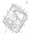
Figure 1 illustrates a perspective view of an accessory module assembly and a mirror assembly forming part of an accessory module system according to the present invention;Figure 2 illustrates a perspective view from the reverse side ofFigure 1 , in which an outer casing of the accessory module assembly has been removed to reveal the internal accessories thereof;Figure 3 illustrates a sectioned side view of the accessory module assembly and mirror module assembly illustrated inFigure 1 ;Figure 4 illustrates a partially exploded view of the accessory module assembly, in which a cover assembly is separated therefrom, and in which the internal accessories have been omitted for clarity;Figure 5 illustrates a perspective view, from behind, of a camera assembly located within the accessory module assembly, showing one method of securing the cover assembly to the frame assembly; andFigure 6 illustrates a perspective view of the accessory module assembly and mirror assembly forming the accessory module system, in which a pair of gaskets are provided on the cover assembly.- Referring now to the accompanying drawings there is illustrated an accessory module system, generally indicated as 10, for mounting against a vehicle window (not shown) in particular a windscreen of a vehicle, as will be described in more detail hereinafter. The
system 10 comprises anaccessory module assembly 12 and, in the preferred embodiment illustrated, amirror assembly 14 detachably connected to themodule assembly 12 in substantially conventional fashion. It will however be appreciated from the following description that themirror assembly 14 does not form an essential element of the invention, and thesystem 10 could be provided without themirror assembly 14. Themodule assembly 12 could be designed to be seated against or partially surrounding an existing mirror assembly mounted directly to the vehicle windscreen. When included, themirror assembly 14 may be of any conventional form, and preferably has a front opening (not shown) which is normally closed by a reflective element (also not shown). The reflective element may comprise an electro-optic cell (such as an electrochromic mirror element) so that the reflectivity of themirror assembly 14 can be electrically varied according to prevailing conditions. The construction and operation of themirror assembly 14 is well known to those skilled in the art, and no further details are therefore deemed necessary. - The
accessory module assembly 12 comprises aframe assembly 16 containing, as will be described in detail hereinafter, a plurality of accessories in the form of electronic components for taking various measurements/readings and/or for controlling various functions of the vehicle to which thesystem 10 is fitted. Theaccessory module assembly 12 further comprises acover assembly 18 detachably connected to theframe assembly 16, and located in use between theframe assembly 16 and the windscreen (not shown) of the vehicle. Thecover assembly 18 performs a number of functions, primarily to shield from view the various components or accessories contained within theaccessory module assembly 12, when viewed from an exterior of the vehicle. In addition, thecover assembly 18 closely conforms to the shape of the windscreen in order to provide an aesthetically pleasing fit between theaccessory module assembly 12 and the windscreen, while also substantially preventing the ingress of contaminants between the windscreen and thecover assembly 18, which might otherwise adversely affect the operation of one or more of the accessories which communication with and/or through the windscreen. These functions, and others, will be described in greater detail hereinafter. - The
accessory module assembly 12 may be mounted against the windscreen by any suitable means, for example using an adhesive or the like. However, in the preferred embodiment illustrated, thesystem 10 comprises an attachment member comprising three discrete fixing elements in the form ofrails 20 which in use are mounted to the vehicle windscreen by an adhesive or the like. There could of course be more orless rails 20 if desired or required. Theframe assembly 16 comprises a mounting portion in the form of three correspondingly positionedrecesses 22 for receiving therails 20, theframe assembly 16 andrails 20 preferably having co-operating retention means (not shown) such as clips or the like, in order to secure theframe assembly 16 to therails 20, and therefore the vehicle windscreen. Alternatively a screw (not shown) or similar fastener element may be passed through theframe assembly 16 and into therespective rail 20. In order to simplify the process of fitting therails 20 to the windscreen, and to eliminate the possibility of inaccurate spacing between each of the threerails 20, therails 20 are preferably initially located within a frame or jig (not shown) which accurately positions therails 20 with respect to one another. The frame or jig can then be positioned against the windscreen in order to simultaneously position each of therails 20, at the correct positions, in contact with the windscreen, to be suitably secured in place, preferably by means of a suitable adhesive. Alternatively, therails 20 could be formed integrally with such a frame or jig, which could then, with therails 20 fixed to the windscreen, form a permanent subframe of theaccessory module assembly 12. This arrangement greatly improves the tolerances achievable, while reducing the time and therefore cost of fitting therails 20 to the windscreen. Further time and cost savings can then be expected when it comes to fitting theframe assembly 16 to therails 20, as the elimination of inaccuracies in spacing between therails 20 will ensure that theframes 16 consistently and accurately fit into position about therails 20. It will also be apparent that any other fixing elements may be employed to allow themodule assembly 12 to be secured against the vehicle windscreen. - On the cabin facing side of the
accessory module assembly 12, there is provided anouter casing 24 surrounding theframe assembly 16 with asupport bracket 26 projecting from theframe assembly 16, through theouter casing 24, to which themirror assembly 14 is connected, preferably by a ball and socket joint or the like. As therails 20 are all recessed inwardly of theframe assembly 16, and with theouter casing 24 in place, theaccessory module assembly 12 is given a "floating" appearance from the vehicle interior. For ease of installation, theouter casing 24 is preferably provided in two parts, as illustrated inFig. 4 , allowing the two parts to be quickly and easily installed/removed on themodule assembly 12. Any suitable means may be provided to secure the two parts together, in addition to securing theouter casing 24 to themodule assembly 12. - Optionally,
accessory module assembly 12 may be a stand-alone module assembly that is separate and distinct from the interior rearview mirror of the vehicle. If so, it may be desirable to include a mirror mounting button as part ofaccessory module assembly 12 so that an interior mirror assembly can be attached thereto in a "button-on-button" attachment manner such as is disclosed in the likes ofUS patent 6,968,736 ;US patent 6,824,281 ; andUS patent 6,690,268 . In this regard, inclusion of a rain sensor (whether contacting or non-contacting such as a capacitive rain sensor being developed by Preh-Werke GmbH & Co. KG of Bad Neustadt, Germany) is contemplated. - Turning then to the interior of the
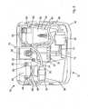
accessory module assembly 12, and as mentioned above, a plurality of accessories or electronic components are housed therein, for performing various functions to and within the vehicle to improve the safety and/or comfort for the vehicle occupants. In the preferred embodiment illustrated, these accessories comprise acamera 28, arain sensor assembly 30, a windscreentemperature sensor assembly 32, a closing velocity (CV)sensor assembly 34, and acompass 36, the configuration and operation of each of which is described in detail below. As will also be described hereinafter, theframe assembly 16 defines a site in the form of anenclosure 29 for thecamera 28, a site in the form of acradle 31 for therain sensor assembly 30, a site in the form of asleeve 33 for thetemperature sensor assembly 32, and a site in the form of anopening 35 for theCV sensor assembly 34. Compass 36 preferably includes a compass sensor, such as a magneto-responsive sensor such as a magneto-resistive sensor, a magneto-capacitive sensor, a magneto-inductive sensor, a Hall effect sensor, or a flux gate sensor and/or a compass display, such as the types disclosed inU.S. Pat. No. 5,802,727 or inU.S. provisional application, Ser. No. 60/636,931, filed Dec. 17, 2004 - All of the above accessories, except the
compass 36, require either direct contact with the vehicle windscreen, or the ability to communicate, through the windscreen, with the exterior of the vehicle, for reasons set out hereinafter. Thus although thecover assembly 18 masks the internal workings of theaccessory module assembly 12 from the exterior of the vehicle, thecover assembly 18 is nevertheless provided with acamera aperture 38 and associatedchannel 40, arain sensor aperture 42, a windscreentemperature sensor aperture 44, atransmitter aperture 46 and associatedchannel 48, and areceiver aperture 50 and associatedchannel 52. These apertures in thecover assembly 18 allow the respective components to communicate with and/or through the windscreen. - Turning firstly to the
camera 28, and referring toFigure 5 , a pair oftabs 54 are provided, one on either side of thecamera 28, to facilitate connection of thecamera 28 to theframe assembly 16. In the preferred embodiment illustrated, the site for thecamera 28, in addition to theopening 29, comprises a pair ofabutments 56 located on theframe assembly 16, to which abutments 56 thetabs 54 are secured by any suitable means, for example screws or the like. When mounted as illustrated, the line of vision of thecamera 28 is directed through thecamera aperture 38 in thecover assembly 18, along the correspondingchannel 40, and in use out through the windscreen of the vehicle. Thecamera 28 may then be employed as part of a collision avoidance system for the vehicle, by focusing the camera a suitable distance beyond the bonnet of the vehicle, with feedback from the camera then being employed to generate warning signals, preferably audio and/or visual warning signals, if a collision seems imminent, or to actively intervene, for example by lightly applying the brakes of the vehicle, in an attempt to avoid any such collision. Such a collision avoidance system in isolation is known, for example as produced by Delphi Automotive Systems of Troy, Michigan, the United States. - Although in the embodiment illustrated the
camera 28 is affixed to theframe assembly 16 via thetabs 54 and correspondingabutments 56, any other suitable mounting means may be employed. For example it is envisaged that connecting means (not shown) could be employed which provide the simultaneous mechanical and electrical connection of thecamera 28 to theframe assembly 16. The same arrangement could be employed for therain sensor assembly 30, windowtemperature sensor assembly 32 and the closingvelocity sensor assembly 34. Such connecting means could for example employ magnetic elements to achieve both the mechanical and electrical connection of one or more of the accessories into theframe assembly 16. Such an arrangement is particularly advantageous where the accessory or associated connection point is in an awkward or out of sight location. - When the
module assembly 12 is fitted to a vehicle, it is necessary to conduct a final alignment of thecamera 28 relative to the exterior of the vehicle, in particular the front of the bonnet. This final alignment is however undertaken in a known manner using dedicated software, which does not therefore require the physical adjustment of thecamera 28 within themodule assembly 12. However, this final software effected alignment is capable of achieving only a small range of adjustment in the x, y and z directions. For this reason, it is desirable that the position of thecamera 28 can be physically adjusted within theframe assembly 16. This adjustment is preferably achieved at the point of mounting thecamera 28 to theframe assembly 16, and in the embodiment illustrated, via thetabs 54 and correspondingabutments 56, which may be suitably modified, although not illustrated, to allow the simple x, y and z axes adjustment of thecamera 28 relative to theframe assembly 16. Alternatively, the adjustment may take the form of calibrating thecamera 28 to theframe assembly 16 by, for example, the addition or removal of material such as shims or similar spacers (not shown) such as to achieve a combined tolerance for thecamera 28 andframe assembly 16. It will of course be understood that any other suitable or equivalent arrangement could be employed to achieve this desired result. It will also be appreciated that similar provisions could be employed for any of the other accessories within thesystem 10. - Turning then to the
rain sensor assembly 30, theframe assembly 16 is provided with thecradle 31 for receiving and retaining therain sensor assembly 30. In order to function correctly, therain sensor assembly 30 must be urged, in use, against the vehicle windscreen with significant force. Thus in use therain sensor assembly 30 is pressed through therain sensor aperture 42 in thecover assembly 18. As no adhesive or the like is to be utilised in securing therain sensor assembly 30 to the windscreen, the force to be applied to therain sensor assembly 30 must thus be applied by theframe assembly 16, via thecradle 31. For this reason it is preferable that theframe assembly 16, and therefore thecradle 31, is formed from a substantially rigid material, for example a metal, and in particular die-cast aluminium or an alloy thereof. Theframe assembly 16 can then be mounted against the windscreen, the rigidity thereof ensuring that theframe assembly 16 is capable of applying, and,maintaining, a suitable force to therain sensor assembly 30 in order to urge same against the windscreen. - The windscreen
temperature sensor assembly 32 is mounted within thesleeve 33 formed integrally with theframe assembly 16, with the free end of the windscreentemperature sensor assembly 32 projecting through the windscreentemperature sensor aperture 44 to contact and be urged against the interior surface of the vehicle windscreen. In this way, and as described in our co-pending International Patent Application No.PCT/EP2005/010071 temperature sensor assembly 32 can be used in combination with additional sensor assemblies (not shown) to predict internal misting of the vehicle windshield, and take active steps to prevent such an occurrence, for example by activating an air conditioning system (not shown) of the vehicle. Thetemperature sensor assembly 32 may be spring biased within thesleeve 33, in order to ensure that an intimate thermally conductive contact is made between thetemperature sensor assembly 32 and the windscreen. - The preferred closing velocity (CV)
sensor assembly 34 utilises a LIDAR (light detection and ranging) collision-avoidance detector which operates on a similar principle as radar. Basically, theCV sensor assembly 34 emits light, through thetransmitter aperture 46 and associatedchannel 48, through the vehicle windscreen, and forwardly of the vehicle. The transmitted light will then be reflected by a leading vehicle if within a certain range, the reflected light being received by theCV sensor assembly 34, via thereceiver aperture 50 and associatedchannel 52. TheCV sensor assembly 34 can then determine the velocity and range of a leading vehicle, and again take preventative measures to avoid a collision. Again this type of system is already in existence in isolation, for example as manufactured by Continental Temick. To improve the performance/accuracy of theCV sensor assembly 34, it is desirable to substantially eliminate stray or background light being reflected onto theCV sensor 34 from the walls of thechannel 52, as this may lead to false or inaccurate readings. It is therefore preferable that the walls of thechannel 52 are coated or covered with a light absorbing layer or film, which may be in the form of a paint, fabric, or any other suitable coating. - In the preferred embodiment illustrated, the
CV sensor assembly 34 is provided prefixed in a custom mouldedhousing 58 which can then quickly and easily be located and secured within theopening 35 in theframe assembly 16. In order to secure thehousing 58 relative to theframe assembly 16, thehousing 58 is provided with a plurality oftabs 60, with thecover assembly 18 comprising a mounting member in the form of correspondingslots 62 for receiving thetabs 60. Thehousing 58, containing theCV sensor assembly 34, can then quickly and easily be clipped onto the underside of thecover assembly 18, ensuring accurate alignment of theCV sensor assembly 34 with the transmitting and receivingapertures cover assembly 18 is mounted onto theframe assembly 16, thehousing 58, and therefore theCV sensor assembly 34, are positioned within thededicated opening 35 in theframe assembly 16. It will of course be appreciated that any other suitable arrangement may be employed in order to secure thehousing 58 relative to theframe assembly 16. For example, theframe assembly 16 could be provided.with means for receiving thetabs 60. - The
compass 36, in the preferred embodiment illustrated, is provided on a printed circuit board (PCB) mounted on thesupport bracket 26, which thus acts as the site for thecompass 36. It will of course be appreciated that thecompass 36 could be located in any other suitable position within theaccessory module assembly 12. Theouter casing 24 is then provided with awindow 37 formed therein, through whichwindow 37 thecompass 36 is visible from an interior of the vehicle. Thewindow 37 could be enlarged to reveal a display from, or associated with, one or more additional accessories (not shown), for example an environmental control system (not shown) including, for example, a cabin temperature sensor assembly, a humidity sensor assembly, an exterior temperature sensor assembly, a petrol gauge, or any other useful display, Thesystem 10 could also be adapted such that said enlarged display (not shown) could be provided as a separate add on module or component (not shown) which may be clipped or otherwise secured to themodule assembly 12, preferably at or adjacent the site of thewindow 37, in order to be clearly visible to a vehicle occupant, above themirror assembly 14. - In order to reduce the amount of wiring between a vehicle and the
accessory module system 10, anelectrical terminal 64 is provided within theaccessory module assembly 12, and in the embodiment illustrated is adjacent therain sensor assembly 30. The terminal 64 is connected to the vehicle via a single power and/or control cable, namely a first power/control input 66 which passes through theouter casing 24 as illustrated inFigure 4 , across theframe assembly 16, for connection with the terminal 64. Extending out of the terminal 64 is a first power/control outlet 68 which connects to theCV sensor assembly 34, a second power/control outlet 70 which connects to therain sensor assembly 30, and a third power/control outlet 72 which extends into themirror assembly 14, in order to power/control any electronic components contained therein. Thus in this way a plurality of the accessories contained within theaccessory module system 10 may be powered/controlled from a single power/control input 66 provided to theaccessory module assembly 12, thereby greatly reducing the wiring requirements between a vehicle and theaccessory module system 10. - In the embodiment illustrated, the
camera 28 employed utilises complimentary metal oxide semi-conductor (CMOS) circuitry and processing, and as a result requires a separate power/control supply to the remaining accessories within theaccessory module system 10. Thus in the embodiment illustrated a second power/control input 74 is provided between the vehicle and theaccessory module assembly 12, which again passes through theouter casing 24, and terminates in aplug 76. Thecamera 28 is provided with acomplimentary plug 78 which connects to theplug 76 in order to provide power/control to thecamera 28. Thus theaccessory module system 10 requires only two wiring inputs in order to control a plurality of accessories. If thecamera 28 were omitted from theaccessory module system 10, only a single electrical connection would be required between the vehicle and theaccessory module system 10. It will also be apparent that the terminal 64 could be modified to supply power/control to more than the three accessories provided in the preferred embodiment illustrated. Indeed as theaccessory module system 10, and in particular theaccessory module assembly 12, is designed to be modular in nature, allowing the inclusion or omission of one or more of the accessories therein, without affecting the operation of the remaining accessories, the primary function of the terminal 64 is to allow a single incoming wiring configuration to be utilised with theaccessory module system 10, regardless of the internal configuration of accessories contained within theaccessory module assembly 12. If more or less accessories are utilised than in the preferred embodiment illustrated, the first power/control outlet 68,second outlet 70 andthird outlet 72, which together form an internal wiring harness for theaccessory module assembly 12, need simply be replaced with a suitably modified version of same in order to accommodate the array of accessories to be utilised. - Communication between the accessories within the
accessory module assembly 12 and the vehicle systems to be controlled by same, in addition to communication between the accessories within theaccessory module assembly 12 and themirror assembly 14, may take a number of forms, for example using Bluetooth® technology, infrared (IR), or radiofrequency (RF) applications. Such wireless communication will simplify the wiring harness to be used within and to theaccessory module system 10, and therefore also give greater flexibility to thesystem 10 in terms of the interchangability of accessories that can be employed within thesystem 10. Hard wiring will still have to be employed to power the various accessories. However, the various wires could be replaced with a network of electrically conductive strips routed internally of themodule assembly 12, with each branch or strip (not shown) being contacted by the respective accessory or a terminal thereof upon the location of the accessory within theframe assembly 16. - If the number of accessories contained within the
accessory module assembly 12 is to be varied, it is preferable to provide a suitably modified.cover assembly (not shown) to replace thecover assembly 18, which modified cover assembly can then be provided with the correct arrangement of apertures therein to correspond to the accessories being utilised. It will therefore be appreciated that theaccessory module system 10 is modular in form and function. - As detailed above, due to the requirement for the
rain sensor assembly 30 and thetemperature sensor assembly 32 to be pressed against the windscreen with significant force, theframe assembly 16 is preferably formed from a substantially rigid material such as a metal or the like. For this reason, and as a result of manufacturing tolerances both in producing theaccessory module system 10, and in producing the vehicle windscreen, the shape of theframe assembly 16 is unlikely to exactly match that of the curved windscreen of the vehicle, which may therefore result in slight gaps being present between theframe assembly 16 and the windscreen, negatively affecting the aesthetics of theaccessory module system 10 when fitted. In addition, such gaps may allow the ingress of dirt/dust or the like contaminants between the windscreen and themodule assembly 12, which may then obscure the vision of one or more of the accessories. For this reason, thecover assembly 18 is preferably formed from a resiliently deformable material, and is thus capable of deforming to conform substantially precisely to the shape of the windscreen, regardless of any slight deviations in dimensions due to manufacturing tolerances. Thus from the exterior of the vehicle thecover assembly 18 will provide the appearance of forming a perfect match between theaccessory module assembly 12 and the vehicle windscreen, which should therefore prevent any dirt/dust from migrating between the windscreen and themodule assembly 12. Although not illustrated in the preferred embodiment, it is also envisaged that thecover assembly 18 be resiliently or spring-mounted to theframe assembly 16, in order, in use, to actively urge thecover assembly 18 against the windscreen, in order to fully conform to the shape thereof. - The
system 10 also preferably comprises the use of a frit (not shown) on the vehicle windscreen (not shown), at the position at which theaccessory module assembly 12 is mounted. The frit should then be provided with clear areas corresponding in position and shape to the apertures and/or channels formed in thecover assembly 18. - Due to the position of the
accessory module assembly 12 on the windscreen or other window of a vehicle, theaccessory module assembly 12 will be subjected, in use, to significant incident radiation, in particular solar radiation, which could result in heating of theaccessory module assembly 12, possibly adversely affecting the accessories contained therein. For this reason, thecover assembly 18 preferably comprises a heat deflecting material, more preferably a material having a heat deflection temperature of at least 75°C, more preferably at least 85°C, and most preferably at least 105°C. - In certain environmental conditions, it is possible that the area of windscreen effectively enclosed by the
module assembly 12, and in particular by the various apertures in thecover assembly 18, may become misted/fogged, or otherwise obscured, thereby negatively affecting the performance of the various accessories in thesystem 10, which generally require a clear field of vision through the windscreen in order to perform effectively. In order to prevent such an occurrence, and referring toFig. 6 , themodule assembly 12 is preferably provided with a first fluidimpermeable gasket 80 surrounding thecamera aperture 38 and associatedchannel 40, and a second fluidimpermeable gasket 82 surrounding thetransmitter aperture 46 and associatedchannel 48 and thereceiver aperture 50 and associatedchannel 52. Thesegaskets channels - As a further measure, it is proposed that a respective vent or port (not shown) be provided, communicating with the otherwise sealed space or cavity defined by the
gaskets respective channels - In the absence of such a membrane, the air being channelled through the respective port could be directed over a relatively cool surface, for example the
metal frame assembly 16, which would then cause a significant portion of any water vapour in the air to condense out onto the relatively cool surface, thus reducing or eliminating the occurrence of misting/fogging in said spaces. Alternatively the air may be channelled through a suitably designed baffle (not shown) which is adapted to permit the passage of heated air, but not any moisture contained therein, to reach the otherwise sealed spaces defined by thegaskets camera 28 andCV sensor assembly 34, to have a clear view through the windscreen in order to operate correctly, the frost must first be cleared from the windscreen. This is normally achieved using heated air blown up and along the interior surface of the windscreen form the vehicles air conditioning system, which heats the windscreen through to the outer surface, thereby dispersing or melting the frost. However as a result of thegaskets camera 28 andCV sensor assembly 34 look, and these areas must therefore be heated from within themodule assembly 12 as described above. - It will of course be appreciated that any other measure may be taken to reduce or eliminate misting, fogging or frost on that portion of the windscreen against which the
module assembly 12 is seated. - The
accessory module assembly 12 can house a large array of sensor assemblies and other components, other than those describe in detail above, for example a cabin temperature sensor assembly, a cabin humidity sensor assembly, an ambient light and a glare sensor assembly for an electrochromic (EC) mirror cell, a phone system, petrol gauge display, and any other desired components or accessories. Many of these accessories were previously housed with a vehicles rearview mirror, and thus the provision of theaccessory module assembly 12 can generate a relatively large amount of free space within the vehicles rearview mirror assembly. As a result, themirror assembly 14 could be significantly reduced in size, in particular in depth or thickness, and especially where an EC cell is employed, thereby providing an aesthetically pleasing appearance. Alternatively or simultaneously, this additional space may be used to apply one or more digital displays to the rear of the EC cell, which can then display information, through the EC cell, to a driver or passenger of the vehicle. - It will thus be appreciated that the
accessory module system 10 of the present invention provides a convenient location in which to house a large array of accessories and/or sensors or the like, and which is modular in terms of the combination of said accessories which may be housed within same. - The accessory module or
system 10 of the present invention may utilize aspects of other accessory modules or windshield electronics modules or the like, such as modules of the types described inU.S. pat. application Ser. No. 10/958,087, filed Oct. 4, 2004 by Schofield et al. U.S. Pat. No. 7,188,963 ; Ser. No.10/456,599, filed Jun. 6, 2003 by Weller et al. U.S. Pat. No. 7,004,593 ; and/or Ser. No.11/201,661, filed Aug. 11,2005 U.S. Pat. No. 7,480,149 , and/orU.S. Pat. Nos. 6,824,281 ;6,690,268 ;6,250,148 ;6,341,523 ;6,593,565 ;6,428,172 ;6,501,387 ;6,329,925 ; and6,326,613 , and/or in PCT Application No.PCT/US03/40611, filed Dec. 19, 2003 by Donnelly Corp. et al. for ACCESSORY SYSTEM FOR VEHICLE, and/or Ireland pat. applications, Ser. No.S2004/0614, filed Sep. 15,2004 S2004/0838, filed Dec. 14, 2004 S2004/0840, filed Dec. 15,2004 - The interior
rearview mirror assembly 14 of theaccessory module system 10 may include an electro-optic reflective element or a prismatic reflective element. For example, the reflective element may comprise an electro-optic or electrochromic reflective element assembly or cell, and the electrochromic reflective element assembly of the electrochromic mirror assembly may utilize the principles disclosed in commonly assignedU.S. Pat. Nos. 6,690,268 ;5,140,455 ;5,151,816 ;6,178,034 ;6,154,306 ;6,002,544 ;5,567,360 ;5,525,264 ;5,610,756 ;5,406,414 ;5,253,109 ;5,076,673 ;5,073,012 ;5,117,346 ;5,724,187 ;5,668,663 ;5,910,854 ;5,142,407 ;5,142,406 ;5,442,478 ; and/or4,712,879 , and/or as disclosed in the following publications:N. R. Lynam, "Electrochromic Automotive Day/Night Mirrors", SAE Technical Paper Series 870636 (1987);N. R. Lynam, "Smart Windows for Automobiles", SAE Technical Paper Series 900419 (1990);N. R. Lynam and A. Agrawal, "Automotive Applications of Chromogenic Materials", Large Area Chromogenics: Materials and Devices for Transmittance Control, C.M. Lampert and C.G. Granquist, EDS., Optical Engineering Press, Wash. (1990); and/or as described inU.S. pat. application, Ser. No. 10/054,633, filed Jan. 22, 2002 , nowU.S. Pat. No. 7,195,381 . Optionally, the electrochromic circuitry and/or a glare sensor (such as a rearward facing glare sensor that receives light from rearward of the mirror assembly and vehicle through a port or opening along the casing and/or bezel portion and/or reflective element of the mirror assembly) and circuitry and/or an ambient light sensor and circuitry may be provided on one or more circuit boards of the mirror assembly. - The
mirror assembly 14 may include one or more other displays, such as the types disclosed inU.S. Pat. Nos. 5,530,240 and/or6,329,925 , and/or display-on-demand transflective type displays, such as the types disclosed inU.S. Pat. Nos. 6,690,268 ;5,668,663 and/or5,724,187 , and/or inU.S. patent applications Ser. No. 10/054,633, filed Jan. 22,2002 by Lynam et al. for VEHICULAR LIGHTING SYSTEM, nowU.S. Pat. No. 7,195,381 ; Ser. No.10/528,269, filed Mar. 17, 2005 U.S. Pat. No. 7,274,501 ; Ser. No.10/533,762, filed May 4, 2005 U.S. Pat. No. 7,184,190 ; Ser. No.10/538,724, filed Jun. 13, 2005 by Hutzel et al. 11/021,065, filed Dec. 23, 2004 by McCabe et al. U.S. Pat. No. 7,255,451 ; and/or Ser. No.11/226,628, filed Sep. 14, 2005 by Karner et al. PCT/US03/29776, filed Sep. 9, 2003 by Donnelly Corp. et al. for MIRROR REFLECTIVE ELEMENT ASSEMBLY; PCT Application No.PCT/US03/35381, filed Nov. 5, 2003 by Donnelly Corp. et al. for ELECTRO-OPTIC REFLECTIVE ELEMENT ASSEMBLY; and/or PCT Application No.PCT/US03/40611, filed Dec. 19, 2003 by Donnelly Corp. et al. for ACCESSORY SYSTEM FOR VEHICLE. - Optionally, the
mirror assembly 14 may comprise a prismatic mirror assembly, such as a prismatic mirror assembly utilizing aspects described inU.S. Pat. Nos. 6,318,870 ;6,598,980 ;5,327,288 ;4,948,242 ;4,826,289 ;4,436,371 ; and4,435,042 ; and PCT Application No.PCT/US04/015424, filed May 18, 2004 by Donnelly Corporation et al. for MIRROR ASSEMBLY FOR VEHICLE; andU.S. pat. application, Ser. No. 10/933,842, filed Sep. 3, 2004 U.S. Pat. No. 7,249,860 . Optionally, the prismatic reflective element may comprise a conventional prismatic reflective element or prism, or may comprise a prismatic reflective element of the types described in PCT Application No.PCT/US03/29776, filed Sep. 19, 2003 by Donnelly Corp. et al. for MIRROR REFLECTIVE ELEMENT ASSEMBLY;U.S. pat. applications, Ser. No. 10/709,434, filed May 5, 2004 by Lynam U.S. Pat. No. 7,420,756 ; Ser. No.10/933,842, filed Sep. 3, 2004 by Kulas et al. U.S. Pat. No. 7,249,860 ; Ser. No.11/021,065, filed Dec. 23, 2004 by McCabe et al. U.S. Pat. No. 7,255,451 ; Ser. No.10/528,269, filed Mar. 17,2005 U.S. Pat. No. 7,274,501 ; and/or Ser. No.10/993,302, filed Nov. 19,2004 by Lynam U.S. Pat. No. 7,338,177 , and/or PCT Application No.PCT/US2004/015424, filed May 18,2004 by Donnelly Corp. et al. for MIRROR ASSEMBLY FOR VEHICLE. A variety of mirror accessories and constructions are known in the art, such as those disclosed inU.S. Pat. Nos. 5,555,136 ;5,582,383 ;5,680,263 ;5,984,482 ;6,227,675 ;6,229,319 ; and6,315,421 , that can benefit from the present invention. Optionally, themirror assembly 14 may comprise an electro-optic or electrochromic reflective element assembly, as discussed below. - Optionally, the
accessory module 12 and/ormirror assembly 14 and/oraccessory module system 10 may include one or more displays, such as for the accessories or circuitry described herein. The displays may be similar to those described above, or may be of types disclosed inU.S. Pat. Nos. 5,530,240 and/or6,329,925 , or may be display-on-demand or transflective type displays or other displays, such as the types disclosed inU.S. Pat. Nos. 6,690,268 ;5,668,663 and/or5,724,187 , and/or inU.S. pat. applications, Ser. No. 10/054,633, filed Jan. 22, 2002 by Lynam et al. for VEHICULAR LIGHTING SYSTEM, nowU.S. Pat. No. 7,195,381 ; Ser. No.11/021,065, filed Dec. 23, 2004 by McCabe et al. U.S. Pat. No. 7,255,451 ; Ser. No.11/226,628, filed Sep. 14, 2005 by Karner et al. 10/993,302, filed Nov. 19, 2004 U.S. Pat. No. 7,338,177 ; and/or Ser. No.11/284,543, filed Nov. 22, 2005 U.S. Pat. No. 7,370,983 , and/or PCT Application No.PCT/US03/29776, filed Sep. 9, 2003 by Donnelly Corp. et al. for MIRROR REFLECTIVE ELEMENT ASSEMBLY; and/or PCT Application No.PCT/US03/35381, filed Nov. 5, 2003 by Donnelly Corp. et al. for ELECTRO-OPTIC REFLECTIVE ELEMENT ASSEMBLY; and/orU.S. provisional applications, Ser. No. 60/630,061, filed Nov. 22, 2004 by Lynam et al. 60/667,048, filed Mar. 31, 2005 by Lynam et al. 60/629,926, filed Nov. 22, 2004 by McCabe et al. 60/531,838, filed Dec. 23, 2003 60/553,842, filed Mar. 17, 2004 60/563,342, filed Apr. 19, 2004 60/681,250, filed May 16, 2005 60/690,400, filed Jun. 14, 2005 60/695,149, filed Jun. 29, 2005 60/717,093, filed Sep. 14, 2005 by Lynam 60/730,334, filed Oct. 26, 2005 by Baur 60/732,245, filed Nov. 1, 2005 PCT/US03/40611, filed Dec. 19, 2003 by Donnelly Corp. et al. for ACCESSORY SYSTEM FOR VEHICLE, or may include or incorporate video displays or the like, such as the types described inPCT Application No. PCT/US03/40611, filed Dec. 19, 2003 by Donnelly Corp. et al. for ACCESSORY SYSTEM FOR VEHICLE,U.S. patent application Ser. No. 11/284,543, filed Nov. 22, 2005 U.S. Pat. No. 7,370,983 , and/orU.S. provisional applications, Ser. No. 60/630,061, filed Nov. 22, 2004 by Lynam et al. 60/667,048, filed Mar. 31, 2005 by Lynam et al. - Optionally, the display and inputs may be associated with various accessories or systems, such as, for example, a tire pressure monitoring system or a passenger air bag status or a garage door opening system or a telematics system or any other accessory or system of the mirror assembly or of the vehicle or of an accessory module or console of the vehicle, such as an accessory module or console of the types described in
U.S. Pat. Nos. 6,690,268 ;6,672,744 ;6,386,742 ; and6,124,886 , and/orU.S. pat. applications, Ser. No. 10/739,766, filed Dec. 18, 2003 by DeLine et al. U.S. Pat. No. 6,877,888 ; and/or Ser. No.10/355,454, filed Jan. 31, 2003 by Schofield et al. U.S. Pat. No. 6,824,281 , and/or PCT Application No.PCT/US03/03012, filed Jan. 31, 2003 by Donnelly Corporation for VEHICLE ACCESSORY MODULE, and/or PCT Application No.PCT/US03/40611, filed Dec. 19, 2003 by Donnelly Corporation for ACCESSORY SYSTEM FOR VEHICLE, and/or PCT Application No.PCT/US04/15424, filed May 18, 2004 by Donnelly Corporation et al. for MIRROR ASSEMBLY FOR VEHICLE. - Optionally, the
accessory module 12 and/ormirror assembly 14 may support one or more other accessories or features, such as one or more electrical or electronic devices or accessories. For example, illumination sources or lights, such as map reading lights or one or more other lights or illumination sources, such as illumination sources of the types disclosed inU.S. Pat. Nos. 6,690,268 ;5,938,321 ;5,813,745 ;5,820,245 ;5,673,994 ;5,649,756 ;5,178,448 ;5,671,996 ;4,646,210 ;4,733,336 ;4,807,096 ;6,042,253 ;6,971,775 ; and/or5,669,698 , and/orU.S. pat. applications, Ser. No. 10/054,633, filed Jan. 22,2002 , nowU.S. Pat. No. 7,195,381 ; and/or Ser. No.10/933,842, filed Sep. 3, 2004 by Kulas et al. U.S. Pat. No. 7,249,860 , may be included in the mirror assembly. The illumination sources and/or the circuit board may be connected to one or more buttons or inputs for activating and deactivating the illumination sources. Optionally, theaccessory module 12 and/ormirror assembly 14 may also or otherwise include other accessories, such as microphones, such as analog microphones or digital microphones or the like, such as microphones of the types disclosed inU.S. Pat. Nos. 6,243,003 ;6,278,377 ; and/or6,420,975 , and/or in PCT Application No.PCT/US03/308877, filed Oct. 1, 2003 by Donnelly Corp. et al. for MICROPHONE SYSTEM FOR VEHICLE. Optionally, the accessory module and/or mirror assembly may also or otherwise include other accessories, such as a telematics system, speakers, antennas, including global positioning system (GPS) or cellular phone antennas, such as disclosed inU.S. Pat. No. 5,971,552 , a communication module, such as disclosed inU.S. Pat. No. 5,798,688 , a voice recorder, a blind spot detection system, such as disclosed inU.S. Pat. Nos. 5,929,786 and/or5,786,772 , and/orU.S. pat. applications, Ser. No. 10/427,051, filed Apr. 30, 2003 U.S. Pat. No. 7,038,577 ; and Ser. No.10/209,173, filed Jul. 31, 2002 U.S. Pat. No. 6,882,287 ; and/orU.S. provisional application, Ser. No. 60/638,687, filed Dec. 23,2004 U.S. Pat. No. 5,798,575 , a high/low headlamp controller, such as a camera-based headlamp control, such as disclosed inU.S. Pat. Nos. 5,796,094 and/or5,715,093 , a memory mirror system, such as disclosed inU.S. Pat. No. 5,796,176 , a hands-free phone attachment, an imaging system or components or circuitry or display thereof, such as an imaging and/or display system of the types described inU.S. Pat. Nos. 6,690,268 and6,847,487 ; and/orU.S. provisional applications, Ser. No. 60/614,644, filed Sep. 30, 2004 60/618,686, filed Oct. 14,2004 60/628,709, filed Nov. 17, 2004 60/644,903, filed Jan. 11, 2005 60/667,049, filed Mar. 31, 2005 U.S. pat. applications, Ser. No. 11/105,757, filed Apr. 14, 2005 U.S. Pat. No. 7,526,103 ; and/or Ser. No.11/239,980, filed Sep. 30, 2005 U.S. Pat. No. 7,881,496 , a slide out or extendable/retractable video device or module, such as described inU.S. patent application Ser. No. 11/284,543, filed Nov. 22, 2005 U.S. Pat. No. 7,370,983 ,U.S. provisional applications, Ser. No. 60/630,061, filed Nov. 22, 2004 60/667,048, filed Mar. 31, 2005 PCT/US03/40611, filed Dec. 19, 2003 , a video device for internal cabin surveillance (such as for sleep detection or driver drowsiness detection or the like) and/or video telephone function, such as disclosed inU.S. Pat. Nos. 5,760,962 and/or5,877,897 , a remote keyless entry receiver, a seat occupancy detector, a remote starter control, a yaw sensor, a clock, a carbon monoxide detector, status displays, such as displays that display a status of a door of the vehicle, a transmission selection (4wd/2wd or traction control (TCS) or the like), an antilock braking system, a road condition (that may warn the driver of icy road conditions) and/or the like, a trip computer, a tire pressure monitoring system (TPMS) receiver (such as described inU.S. Pat. Nos. 6,124,647 ;6,294,989 ;6,445,287 ;6,472,979 ; and/or6,731,205 ; and/orU.S. patent application Ser. No. 11/232,324, filed Sep. 21, 2005 by O'Brien et al. U.S. Pat. No. 7,423,522 ; and/orU.S. provisional application, Ser. No. 60/611,796, filed Sep. 21, 2004 - Optionally, the
accessory module 12 and/ormirror assembly 14 may accommodate other accessories or circuitry or the like as well, such as a rain sensor or imaging device or the like. For example, the accessory module and/or mirror assembly may include a mounting portion (such as the types described inU.S. patent application Ser. No. 11/226,628, filed Sep. 14, 2005 U.S. provisional applications, Ser. No. 60/692,113, filed Jun. 20, 2005 60/677,990, filed May 5, 2005 60/653,787, filed Feb. 17,2005 60/642,227, filed Jan. 7, 2005 60/638,250, filed Dec. 21, 2004 60/624,091, filed Nov. 1, 2004 60/609,642, filed Sep. 14, 2004 U.S. Pat. Nos. 6,250,148 ;6,341,523 ;6,516,664 ;6,968,736 ; and6,824,281 , and inU.S. pat. application Ser. No. 10/958,087, filed Oct. 4, 2004 by Schofield et al. U.S. Pat. No. 7,188,963 . Optionally, theaccessory module 12 and/ormirror assembly 14 may include an imaging device, such as an imaging array sensor for imaging systems of the types described inU.S. Pat. Nos. 6,757,109 ;6,717,610 ;6,396,397 ;6,201,642 ;6,353,392 ;6,313,454 ;6,396,397 ;5,550,677 ;5,670,935 ;5,796,094 ;5,877,897 ;6,097,023 ; and6,498,620 , andU.S. pat. applications, Ser. No. 09/441,341, filed Nov. 16, 1999 by Schofield et al. U.S. Pat. No. 7,339,149 , and Ser. No.10/427,051, filed Apr. 30, 2003 U.S. Pat. No. 7,038,577 . - Optionally, the
accessory module 12 and/ormirror assembly 14 may include one or more user inputs for controlling or activating/deactivating one or more electrical accessories or devices of or associated with the mirror assembly. Theaccessory module 12 and/ormirror assembly 14 may comprise any type of switches or buttons, such as touch or proximity sensing switches, such as touch or proximity switches of the types described in PCT Application No.PCT/US03/40611, filed Dec. 19,2003 by Donnelly Corporation for ACCESSORY SYSTEM FOR VEHICLE; and/orU.S. Pat. Nos. 6,001,486 ;6,310,611 ;6,320,282 ; and6,627,918 ; and/orU.S. patent application Ser. No. 11/021,065, filed Dec. 23, 2004 , nowU.S. Pat. No. 7,255,451 ; and/orU.S. pat. applications, Ser. No. 09/817,874, filed Mar. 26, 2001 by Quist et al. U.S. Pat. No. 7,224,324 ; Ser. No.10/956,749, filed Oct. 1, 2004 by Schofield et al. U.S. Pat. No. 7,446,924 ; Ser. No.10/933,842, filed Sep. 3, 2004 by Kulas et al. U.S. Pat. No. 7,249,860 ; Ser. No.11/021,065, filed Dec. 23, 2004 U.S. Pat. No. 7,255,451 ; and/or Ser. No.11/140,396, filed May 27,2005 U.S. Pat. No. 7,360,932 ; and/orU.S. provisional application, Ser. No. 60/563,342, filed Apr. 19, 2004 by Bareman et al. U.S. pat. application, Ser. No. 11/029,695, filed Jan. 5, 2005 , nowU.S. Pat. No. 7,253,723 ; and/orU.S. provisional applications, Ser. No. 60/553,517, filed Mar. 16, 2004 60/535,559, filed Jan. 9, 2004 60/690,401, filed Jun. 14, 2005 60/719,482, filed Sep. 22, 2005 U.S. Pat. Nos. 6,504,531 ;6,501,465 ;6,492,980 ;6,452,479 ;6,437,258 ; and6,369,804 . Other types of switches or buttons or inputs or sensors may be incorporated to provide the desired function, without affecting the scope of the present invention. - Optionally, the user inputs or buttons may comprise user inputs for a garage door opening system, such as a vehicle based garage door opening system of the types described in
U.S. Pat. Nos. 6,396,408 ;6,362,771 ; and5,798,688 , and/orU.S. patent application Ser. No. 10/770,736, filed Feb. 3, 2004 U.S. Pat. No. 7,023,322 ; and/orU.S. provisional applications, Ser. No. 60/502,806, filed Sep. 12, 2003 by Taylor et al. 60/444,726, filed Feb. 4, 2003 by Baumgardner et al. U.S. Pat. Nos. 4,862,594 ;4,937,945 ;5,131,154 ;5,255,442 ;5,632,092 ;5,798,688 ;5,971,552 ;5,924,212 ;6,243,003 ;6,278,377 ;6,420,975 ;6,946,978 ; and6,477,464 ; and/or6,678,614 ; and/orU.S. pat. applications, Ser. No. 10/456,599, filed Jun. 6, 2003 by Weller et al. U.S. Pat. No. 7,004,593 ; Ser. No.10/645,762, filed Aug. 20, 2003 by Taylor et al. U.S. Pat. No. 7,167,796 ; and Ser. No.10/964,512, filed Oct. 13, 2004 U.S. Pat. No. 7,308,341 ; and/or PCT Application No.PCT/US03/40611, filed Dec. 19, 2003 by Donnelly Corporation et al. for ACCESSORY SYSTEM FOR VEHICLE, and/or PCT Application No.PCT/US03/308877, filed Oct. 1, 2003 by Donnelly Corp. for MICROPHONE SYSTEM FOR VEHICLE.
Claims (19)
- An accessory module system suitable for use in a vehicle, the accessory module system (10) comprising:a plurality of discrete fixing elements (20) configured for adhesive attachment at a surface of a vehicle windshield;wherein, when adhesively attached at the surface of the vehicle windshield, the fixing elements (20) are spaced apart from one another at the surface of the vehicle windshield;characterized in that: each of the,fixing elements (20) comprises a portion that is configured for adhesive attachment at the surface of the vehicle windshield and a portion that extends from the portion adhesively attached at the surface of the vehicle windshield in a direction away from the vehicle windshield;an accessory module assembly (12) for receiving an accessory and comprising a frame assembly (16);wherein the frame assembly (16) defines a plurality of sites for the modular location of accessories within the frame assembly;wherein the accessory module assembly (12) comprises a plurality of individual receiving portions (22) that are positioned relative to one another in a manner that corresponds with the spacing of the fixing elements (20);wherein each one of the receiving portions (22) is configured to receive a respective and corresponding portion of the fixing element (20) that extends from the portion adhesively attached at the surface of the vehicle windshield in a direction away from the vehicle windshield;wherein the accessory module assembly and the fixing elements cooperate to retain the accessory module assembly at the vehicle windshield;wherein the accessory comprises a camera (28);wherein, when the accessory is received at the accessory module assembly, the line of vision of the camera passes through an aperture existing in the accessory module assembly (12);wherein, with the accessory received at the accessory module assembly (12) and with the accessory assembly (12) attached by the fixing elements (20) at the vehicle windshield, the line of vision of the camera (28) passes through the vehicle windshield; andwherein the accessory module assembly further comprises a cover assembly (18) detachably connectable to the frame assembly (16).
- An accessory module system according to claim 1 in which the cover assembly (18) is resiliently mounted to the frame assembly such that the cover assembly is urged, in use, against the vehicle windshield.
- An accessory module system according to claim 2 in which the cover assembly (18) comprises a resiliently deformable cover assembly detachably connectable to the frame assembly (16) such that the cover assembly is capable of deforming to conform to the shape of the vehicle windshield.
- An accessory module system according to claim 1 in which at least one of the sites comprises a connector assembly configured to provide the simultaneous mechanical and electrical connection of a corresponding accessory to the accessory module assembly.
- An accessory module system according to any preceding claim comprising an electrical terminal having a single power and/or control input (74) and a plurality of power and/or control outputs.
- An accessory module system according to claim 1 in which at least one of the sites comprises a cradle (31) for receiving and supporting one of the accessories therein.
- An accessory module system according to any preceding claim comprising a mirror assembly (14) detachably connectable to the accessory module assembly.
- An accessory module system according to claim 7 in which the mirror assembly is in electrical communication with the accessory module assembly.
- An accessory module system according to any preceding claim in which the accessory module assembly (12) further comprises a cover assembly (18), and wherein the cover assembly (18) comprises at least one aperture (38) to enable a corresponding accessory to communicate with and/or through the vehicle windshield.
- An accessory module system according to any preceding claim in which the frame assembly (16) comprises a corresponding mounting portion configured for releasable engagement with and/or about the fixing elements.
- An accessory module system according to claim 10 in which the plurality of discrete fixing elements comprises three or more discrete fixing elements, and wherein the portion adhesively attached at the surface of the vehicle windshield comprises a rail adhesively attached at the surface of the vehicle windshield.
- An accessory module system according to claim 10 in which the vehicle windshield comprises a frit having at least one aperture corresponding substantially in shape and orientation to the at least one aperture in the cover assembly.
- An accessory module system according to any preceding claim comprising ventilation means to facilitate cooling of the accessory module assembly.
- An accessory module system according to claim 13 in which the ventilation means comprises a plurality of ventilation openings in the accessory module assembly.
- An accessory module system according to any preceding claim in which the accessory module assembly (12) further comprises a cover assembly (18), and wherein the cover assembly comprises a material having a heat deflection temperature of at least 75°C, preferably at least 85°C, and most preferably at least 105°C.
- An accessory module system according to any preceding claim comprising a plurality of accessories.
- An accessory module system according to claim 16 in which the accessories comprise one or more of a closing velocity sensor assembly, a rain sensor assembly, a window temperature sensor assembly, a compass assembly, a communications assembly, a light sensor assembly, a humidity sensor assembly, and a display assembly.
- An accessory module system according to claim 17 in which the accessories comprise a closing velocity sensor assembly and wherein the closing velocity sensor assembly comprises a LIDAR sensor assembly.
- An accessory module system according to claim 1 in which at least one of the sites comprises means for adjusting the position of an accessory locatable within the site.
Applications Claiming Priority (2)
| Application Number | Priority Date | Filing Date | Title |
|---|---|---|---|
| IES20040840 | 2004-12-15 | ||
| PCT/EP2005/013485WO2006063827A1 (en) | 2004-12-15 | 2005-12-14 | An accessory module system for a vehicle window |
Publications (2)
| Publication Number | Publication Date |
|---|---|
| EP1827908A1 EP1827908A1 (en) | 2007-09-05 |
| EP1827908B1true EP1827908B1 (en) | 2015-04-29 |
Family
ID=36177291
Family Applications (1)
| Application Number | Title | Priority Date | Filing Date |
|---|---|---|---|
| EP20050850274Not-in-forceEP1827908B1 (en) | 2004-12-15 | 2005-12-14 | An accessory module system for a vehicle window |
Country Status (3)
| Country | Link |
|---|---|
| US (4) | US8256821B2 (en) |
| EP (1) | EP1827908B1 (en) |
| WO (1) | WO2006063827A1 (en) |
Cited By (4)
| Publication number | Priority date | Publication date | Assignee | Title |
|---|---|---|---|---|
| WO2018015312A1 (en)* | 2016-07-19 | 2018-01-25 | Agc Glass Europe | Glass for autonomous car |
| WO2018178278A1 (en)* | 2017-03-30 | 2018-10-04 | Agc Glass Europe | Glass for autonomous car |
| WO2018178284A1 (en)* | 2017-03-30 | 2018-10-04 | Agc Glass Europe | Glass for autonomous car |
| EA036101B1 (en)* | 2016-11-25 | 2020-09-29 | Агк Гласс Юроп | Glass for autonomous car |
Families Citing this family (202)
| Publication number | Priority date | Publication date | Assignee | Title |
|---|---|---|---|---|
| US6124886A (en) | 1997-08-25 | 2000-09-26 | Donnelly Corporation | Modular rearview mirror assembly |
| US6326613B1 (en) | 1998-01-07 | 2001-12-04 | Donnelly Corporation | Vehicle interior mirror assembly adapted for containing a rain sensor |
| US6445287B1 (en) | 2000-02-28 | 2002-09-03 | Donnelly Corporation | Tire inflation assistance monitoring system |
| US6278377B1 (en)* | 1999-08-25 | 2001-08-21 | Donnelly Corporation | Indicator for vehicle accessory |
| US8288711B2 (en) | 1998-01-07 | 2012-10-16 | Donnelly Corporation | Interior rearview mirror system with forwardly-viewing camera and a control |
| US6420975B1 (en) | 1999-08-25 | 2002-07-16 | Donnelly Corporation | Interior rearview mirror sound processing system |
| AU2001243285A1 (en) | 2000-03-02 | 2001-09-12 | Donnelly Corporation | Video mirror systems incorporating an accessory module |
| US7480149B2 (en) | 2004-08-18 | 2009-01-20 | Donnelly Corporation | Accessory module for vehicle |
| US6396408B2 (en) | 2000-03-31 | 2002-05-28 | Donnelly Corporation | Digital electrochromic circuit with a vehicle network |
| WO2003065084A1 (en) | 2002-01-31 | 2003-08-07 | Donnelly Corporation | Vehicle accessory module |
| DE602005016441D1 (en) | 2004-09-15 | 2009-10-15 | Magna Donnelly Engineering Gmb | CLIMATE CONTROL SYSTEM FOR ONE VEHICLE |
| WO2006063827A1 (en) | 2004-12-15 | 2006-06-22 | Magna Donnelly Electronics Naas Limited | An accessory module system for a vehicle window |
| US8482664B2 (en) | 2008-10-16 | 2013-07-09 | Magna Electronics Inc. | Compact camera and cable system for vehicular applications |
| US8570374B2 (en) | 2008-11-13 | 2013-10-29 | Magna Electronics Inc. | Camera for vehicle |
| WO2010099416A1 (en) | 2009-02-27 | 2010-09-02 | Magna Electronics | Alert system for vehicle |
| US8451332B2 (en) | 2009-03-23 | 2013-05-28 | Magna Mirrors Of America, Inc. | Interior mirror assembly with adjustable mounting assembly |
| US8376595B2 (en) | 2009-05-15 | 2013-02-19 | Magna Electronics, Inc. | Automatic headlamp control |
| KR101111230B1 (en) | 2009-10-27 | 2012-02-14 | 주식회사 에스엘미러텍 | Inside mirror device for car |
| US8339453B2 (en)* | 2010-07-14 | 2012-12-25 | Trw Automotive U.S. Llc | Apparatus for use in association with a vehicle |
| US9415662B2 (en) | 2010-08-06 | 2016-08-16 | Trw Automotive U.S. Llc | Method and apparatus for determining temperature and relative humidity for use in a vehicle HVAC system |
| WO2012068331A1 (en) | 2010-11-19 | 2012-05-24 | Magna Electronics Inc. | Lane keeping system and lane centering system |
| US10046716B2 (en)* | 2011-02-10 | 2018-08-14 | Denso Corporation | In-vehicle camera and vehicle control system |
| US9194943B2 (en) | 2011-04-12 | 2015-11-24 | Magna Electronics Inc. | Step filter for estimating distance in a time-of-flight ranging system |
| US9380219B2 (en) | 2011-04-20 | 2016-06-28 | Magna Electronics Inc. | Angular filter for vehicle mounted cameras |
| WO2012145819A1 (en) | 2011-04-25 | 2012-11-01 | Magna International Inc. | Image processing method for detecting objects using relative motion |
| WO2013123161A1 (en)* | 2012-02-17 | 2013-08-22 | Magna Electronics, Inc. | Vehicle vision system with light baffling system |
| US9487159B2 (en)* | 2011-08-02 | 2016-11-08 | Magna Electronics Inc. | Vehicle vision system with camera module mounting bracket |
| US9871971B2 (en)* | 2011-08-02 | 2018-01-16 | Magma Electronics Inc. | Vehicle vision system with light baffling system |
| CN103858425B (en)* | 2011-08-02 | 2018-03-30 | 马格纳电子系统公司 | Vehicle camera system |
| US20140218535A1 (en) | 2011-09-21 | 2014-08-07 | Magna Electronics Inc. | Vehicle vision system using image data transmission and power supply via a coaxial cable |
| EP2766224B1 (en)* | 2011-10-14 | 2018-12-26 | Continental Automotive Systems, Inc. | Integrated rear camera display |
| US10099614B2 (en) | 2011-11-28 | 2018-10-16 | Magna Electronics Inc. | Vision system for vehicle |
| JP5628778B2 (en)* | 2011-11-30 | 2014-11-19 | 日立オートモティブシステムズ株式会社 | In-vehicle camera mounting device |
| US8694224B2 (en) | 2012-03-01 | 2014-04-08 | Magna Electronics Inc. | Vehicle yaw rate correction |
| JP5853795B2 (en)* | 2012-03-19 | 2016-02-09 | 株式会社デンソー | Car camera |
| US10089537B2 (en) | 2012-05-18 | 2018-10-02 | Magna Electronics Inc. | Vehicle vision system with front and rear camera integration |
| DE102012012501B4 (en)* | 2012-06-21 | 2019-10-24 | Volkswagen Aktiengesellschaft | Camera system for a motor vehicle |
| US9340227B2 (en) | 2012-08-14 | 2016-05-17 | Magna Electronics Inc. | Vehicle lane keep assist system |
| DE102013217430A1 (en) | 2012-09-04 | 2014-03-06 | Magna Electronics, Inc. | Driver assistance system for a motor vehicle |
| DE102012017942A1 (en)* | 2012-09-11 | 2014-03-13 | Valeo Schalter Und Sensoren Gmbh | Holding device for holding a sensor device on a window of a motor vehicle |
| US9244249B2 (en)* | 2012-09-28 | 2016-01-26 | Gentex Corporation | Double ball slide on mount with screw over sensor |
| US9707896B2 (en) | 2012-10-15 | 2017-07-18 | Magna Electronics Inc. | Vehicle camera lens dirt protection via air flow |
| US9090234B2 (en) | 2012-11-19 | 2015-07-28 | Magna Electronics Inc. | Braking control system for vehicle |
| US9092986B2 (en) | 2013-02-04 | 2015-07-28 | Magna Electronics Inc. | Vehicular vision system |
| JP2014178474A (en)* | 2013-03-14 | 2014-09-25 | Sony Corp | Digital microscope apparatus, focusing position searching method therefor, and program |
| DE102013205165A1 (en)* | 2013-03-22 | 2014-10-09 | Robert Bosch Gmbh | Camera arrangement for a vehicle and vehicle with such a camera arrangement |
| JP5683629B2 (en)* | 2013-03-27 | 2015-03-11 | オムロンオートモーティブエレクトロニクス株式会社 | Laser radar equipment |
| US10027930B2 (en) | 2013-03-29 | 2018-07-17 | Magna Electronics Inc. | Spectral filtering for vehicular driver assistance systems |
| US9327693B2 (en) | 2013-04-10 | 2016-05-03 | Magna Electronics Inc. | Rear collision avoidance system for vehicle |
| US20140313337A1 (en)* | 2013-04-23 | 2014-10-23 | Magna Electronics Inc. | Vehicle vision system with fastenerless lens attachment |
| US9280202B2 (en) | 2013-05-10 | 2016-03-08 | Magna Electronics Inc. | Vehicle vision system |
| US9260095B2 (en) | 2013-06-19 | 2016-02-16 | Magna Electronics Inc. | Vehicle vision system with collision mitigation |
| US20140375476A1 (en) | 2013-06-24 | 2014-12-25 | Magna Electronics Inc. | Vehicle alert system |
| KR102072542B1 (en)* | 2013-08-30 | 2020-02-03 | 삼성전자주식회사 | Image processing method and electronic device thereof |
| JP6052119B2 (en)* | 2013-09-19 | 2016-12-27 | 株式会社Jvcケンウッド | In-vehicle camera |
| KR101564354B1 (en) | 2013-09-27 | 2015-10-29 | 오용석 | Black-box for vehicle |
| US9487161B2 (en) | 2013-10-04 | 2016-11-08 | Magna Mirrors Of America, Inc. | Accessory system for a vehicle |
| JP6171961B2 (en)* | 2013-11-22 | 2017-08-02 | 株式会社デンソー | Electronic equipment |
| US9499139B2 (en) | 2013-12-05 | 2016-11-22 | Magna Electronics Inc. | Vehicle monitoring system |
| US9988047B2 (en) | 2013-12-12 | 2018-06-05 | Magna Electronics Inc. | Vehicle control system with traffic driving control |
| US9352692B2 (en) | 2014-03-10 | 2016-05-31 | Magna Mirrors Of America, Inc. | Vehicle vision system with camera and mirror mount |
| JP2015193366A (en)* | 2014-03-17 | 2015-11-05 | 日本電産エレシス株式会社 | Manufacturing method of box body for on-vehicle camera, box body for on-vehicle camera, and on-vehicle camera |
| DE102014005803B3 (en)* | 2014-04-19 | 2015-09-17 | Daimler Ag | Motor vehicle with a side mirror-free rearview device |
| US9896039B2 (en) | 2014-05-09 | 2018-02-20 | Magna Electronics Inc. | Vehicle vision system with forward viewing camera |
| US10389016B2 (en) | 2014-05-12 | 2019-08-20 | Magna Electronics Inc. | Vehicle communication system with heated antenna |
| US10266125B2 (en)* | 2014-05-13 | 2019-04-23 | Yuhua Wang | Camera device |
| US11634078B2 (en) | 2014-05-15 | 2023-04-25 | Magna Mirrors Of America, Inc. | Vehicular rearview mirror control system |
| US10967796B2 (en) | 2014-05-15 | 2021-04-06 | Magna Mirrors Of America, Inc. | Interior rearview mirror assembly with low profile mirror |
| DE102014209345A1 (en)* | 2014-05-16 | 2015-11-19 | Robert Bosch Gmbh | Optics carrier, method for producing an optics carrier, apparatus for producing an optics carrier and radar module |
| US9621769B2 (en) | 2014-06-11 | 2017-04-11 | Magna Electronics Inc. | Camera module for vehicle vision system |
| JP6052246B2 (en)* | 2014-07-10 | 2016-12-27 | トヨタ自動車株式会社 | In-vehicle camera mounting structure |
| KR101592737B1 (en)* | 2014-07-17 | 2016-02-12 | 현대자동차주식회사 | Integrated inside mirror assembly of vehicle |
| KR101628503B1 (en)* | 2014-10-27 | 2016-06-08 | 현대자동차주식회사 | Driver assistance apparatus and method for operating thereof |
| JP6480249B2 (en)* | 2014-11-04 | 2019-03-06 | 日本板硝子株式会社 | Windshield |
| CN107110648A (en) | 2014-11-06 | 2017-08-29 | 金泰克斯公司 | The system and method detected for visual range |
| US9744907B2 (en)* | 2014-12-29 | 2017-08-29 | Gentex Corporation | Vehicle vision system having adjustable displayed field of view |
| JP6172174B2 (en)* | 2015-02-06 | 2017-08-02 | トヨタ自動車株式会社 | Vehicle front information acquisition device |
| KR101655814B1 (en)* | 2015-02-10 | 2016-09-08 | 엘지전자 주식회사 | Front Camera Module unified Rear View Mirror of Vehicles |
| JP6197812B2 (en)* | 2015-03-05 | 2017-09-20 | トヨタ自動車株式会社 | In-vehicle camera mounting structure |
| US10112552B2 (en)* | 2015-03-11 | 2018-10-30 | Magna Electronics Inc. | Vehicle vision system with camera viewing through windshield |
| EP3269140A4 (en)* | 2015-03-12 | 2018-08-29 | TRW Automotive U.S. LLC | Low gloss housing assembly for a driver assist system camera |
| US10023118B2 (en) | 2015-03-23 | 2018-07-17 | Magna Electronics Inc. | Vehicle vision system with thermal sensor |
| US10819943B2 (en) | 2015-05-07 | 2020-10-27 | Magna Electronics Inc. | Vehicle vision system with incident recording function |
| US10000156B2 (en) | 2015-06-02 | 2018-06-19 | Magna Mirrors Of America, Inc. | Vehicle mirror mount assembly |
| DE102015214189A1 (en)* | 2015-07-27 | 2017-02-02 | Robert Bosch Gmbh | Scatter light trap for a camera of a mobile unit |
| JP6288034B2 (en)* | 2015-10-08 | 2018-03-07 | マツダ株式会社 | Auxiliary equipment for vehicles |
| JP6365495B2 (en)* | 2015-10-08 | 2018-08-01 | マツダ株式会社 | Auxiliary equipment for vehicles |
| US10137904B2 (en) | 2015-10-14 | 2018-11-27 | Magna Electronics Inc. | Driver assistance system with sensor offset correction |
| US10875403B2 (en) | 2015-10-27 | 2020-12-29 | Magna Electronics Inc. | Vehicle vision system with enhanced night vision |
| US9986136B2 (en) | 2015-10-30 | 2018-05-29 | Magna Electronics Inc. | Vehicle camera with single point imager fixation to lens holder |
| US9881501B2 (en) | 2015-11-02 | 2018-01-30 | Magna Electronics Inc. | Driver assistance system with traffic light alert |
| US10560613B2 (en) | 2015-11-05 | 2020-02-11 | Magna Electronics Inc. | Vehicle camera with modular construction |
| US10250004B2 (en) | 2015-11-05 | 2019-04-02 | Magna Electronics Inc. | Method of forming a connector for an electrical cable for electrically connecting to a camera of a vehicle |
| US10351072B2 (en) | 2015-11-05 | 2019-07-16 | Magna Electronics Inc. | Vehicle camera with modular construction |
| US10230875B2 (en) | 2016-04-14 | 2019-03-12 | Magna Electronics Inc. | Camera for vehicle vision system |
| JP6304205B2 (en)* | 2015-11-11 | 2018-04-04 | トヨタ自動車株式会社 | In-vehicle imaging device |
| US10232798B2 (en) | 2016-01-29 | 2019-03-19 | Veoneer Us, Inc. | Apparatuses for mounting camera arrangements on motor vehicles |
| US11639039B1 (en) | 2016-02-04 | 2023-05-02 | Maurice Paperi | Matching pieces and kits for repairing broken structures and related methods |
| JP6141468B1 (en)* | 2016-02-05 | 2017-06-07 | 三菱電機株式会社 | Car camera |
| US10132971B2 (en) | 2016-03-04 | 2018-11-20 | Magna Electronics Inc. | Vehicle camera with multiple spectral filters |
| US10142532B2 (en) | 2016-04-08 | 2018-11-27 | Magna Electronics Inc. | Camera for vehicle vision system |
| US12140849B2 (en) | 2016-05-02 | 2024-11-12 | Magna Mirrors Of America, Inc. | Multifunctional rearward viewing camera system |
| US10948798B2 (en) | 2016-05-02 | 2021-03-16 | Magna Mirrors Of America, Inc. | Caseless rearview mirror assembly |
| US10647266B2 (en) | 2016-05-17 | 2020-05-12 | Magna Electronics Inc. | Vehicle vision system with forward viewing camera |
| US10838062B2 (en) | 2016-05-24 | 2020-11-17 | Veoneer Us, Inc. | Direct detection LiDAR system and method with pulse amplitude modulation (AM) transmitter and quadrature receiver |
| US10473784B2 (en) | 2016-05-24 | 2019-11-12 | Veoneer Us, Inc. | Direct detection LiDAR system and method with step frequency modulation (FM) pulse-burst envelope modulation transmission and quadrature demodulation |
| US10416292B2 (en) | 2016-05-24 | 2019-09-17 | Veoneer Us, Inc. | Direct detection LiDAR system and method with frequency modulation (FM) transmitter and quadrature receiver |
| US10209709B2 (en)* | 2016-08-15 | 2019-02-19 | Ford Global Technologies, Llc | LIDAR sensor frost detection |
| US10237456B2 (en) | 2016-08-22 | 2019-03-19 | Magna Electronics Inc. | Vehicle camera assembly process |
| WO2018051906A1 (en)* | 2016-09-15 | 2018-03-22 | 株式会社小糸製作所 | Sensor system, sensor module, and lamp device |
| JP6504145B2 (en)* | 2016-11-24 | 2019-04-24 | 株式会社Jvcケンウッド | Vehicle recording device |
| USD858618S1 (en)* | 2016-12-30 | 2019-09-03 | Gentex Corporation | Camera mount |
| US10488738B2 (en)* | 2017-03-08 | 2019-11-26 | Trw Automotive U.S. Llc | Temperature management of a driver assist camera via a vehicle windshield |
| JP6988409B2 (en) | 2017-04-03 | 2022-01-05 | 株式会社デンソー | The camera module |
| US10787112B2 (en)* | 2017-05-17 | 2020-09-29 | Furrion Property Holding Limited | Vehicle light fixture for connecting a camera |
| US10652437B2 (en) | 2017-05-19 | 2020-05-12 | Magna Electronics Inc. | Vehicle camera with aluminum extruded body |
| US10752175B2 (en) | 2017-08-07 | 2020-08-25 | Magna Mirrors Of America, Inc. | Pivot mounting assembly for interior rearview mirror |
| US10527910B2 (en)* | 2017-08-29 | 2020-01-07 | Trw Automotive U.S. Llc | Vehicle driver assist system |
| US10613200B2 (en) | 2017-09-19 | 2020-04-07 | Veoneer, Inc. | Scanning lidar system and method |
| US11460550B2 (en) | 2017-09-19 | 2022-10-04 | Veoneer Us, Llc | Direct detection LiDAR system and method with synthetic doppler processing |
| US10838043B2 (en) | 2017-11-15 | 2020-11-17 | Veoneer Us, Inc. | Scanning LiDAR system and method with spatial filtering for reduction of ambient light |
| US11007940B1 (en)* | 2017-09-25 | 2021-05-18 | August Harris | Detachable rear-view mirror |
| US10684370B2 (en) | 2017-09-29 | 2020-06-16 | Veoneer Us, Inc. | Multifunction vehicle detection system |
| US11194022B2 (en) | 2017-09-29 | 2021-12-07 | Veoneer Us, Inc. | Detection system with reflection member and offset detection array |
| US10855890B2 (en) | 2017-10-23 | 2020-12-01 | Magna Electronics Inc. | Camera for vehicle vision system with enhanced heat removal |
| US10232780B1 (en)* | 2017-10-25 | 2019-03-19 | Nissan North America, Inc. | Vehicle camera cover assembly |
| US10457222B2 (en)* | 2017-11-06 | 2019-10-29 | Ford Global Technologies, Llc | Electronics systems cluster with interlocking brackets |
| US11585901B2 (en) | 2017-11-15 | 2023-02-21 | Veoneer Us, Llc | Scanning lidar system and method with spatial filtering for reduction of ambient light |
| US10682966B2 (en) | 2017-11-16 | 2020-06-16 | Magna Electronics Inc. | Vehicle light/display control system using camera |
| JP6922705B2 (en)* | 2017-12-06 | 2021-08-18 | トヨタ自動車株式会社 | Sensor mounting structure |
| JP6922706B2 (en)* | 2017-12-06 | 2021-08-18 | トヨタ自動車株式会社 | Sensor mounting structure |
| DE202018100186U1 (en) | 2018-01-15 | 2018-01-26 | Sensirion Automotive Solutions Ag | Sensor module for air quality measurement |
| TWM563372U (en)* | 2018-02-01 | 2018-07-11 | 雄鉅實業有限公司 | Electronic device with L-shaped fastening device |
| DE102018202758A1 (en)* | 2018-02-23 | 2019-08-29 | Audi Ag | Sensor device for a motor vehicle, method and motor vehicle |
| DE102018204438B3 (en) | 2018-03-22 | 2019-05-02 | Conti Temic Microelectronic Gmbh | Device with a sensor assembly and a lens hood |
| US11148578B2 (en)* | 2018-03-25 | 2021-10-19 | Maurice Paperi | Universal mounting tabs and kits for automotive components |
| US10640043B2 (en) | 2018-05-08 | 2020-05-05 | Magna Electronics Inc. | Vehicular rain sensing system using forward viewing camera |
| US10899275B2 (en) | 2018-06-27 | 2021-01-26 | Magna Electronics Inc. | Vehicular camera with PCB focus tuning |
| US10676041B2 (en) | 2018-07-06 | 2020-06-09 | Magna Electronics Inc. | Vehicular camera with pliable connection of PCBS |
| JP7024634B2 (en)* | 2018-07-09 | 2022-02-24 | Agc株式会社 | Mounting base and vehicle glass with mounting base |
| US11124130B2 (en) | 2018-08-01 | 2021-09-21 | Magna Electronics Inc. | Vehicular forward viewing camera |
| US10957023B2 (en) | 2018-10-05 | 2021-03-23 | Magna Electronics Inc. | Vehicular vision system with reduced windshield blackout opening |
| DE102018125065B3 (en)* | 2018-10-10 | 2019-11-21 | Bayerische Motoren Werke Aktiengesellschaft | Holding device for holding at least one driver assistance sensor unit and arrangement of a holding device |
| US11683911B2 (en) | 2018-10-26 | 2023-06-20 | Magna Electronics Inc. | Vehicular sensing device with cooling feature |
| US10911647B2 (en) | 2018-11-12 | 2021-02-02 | Magna Electronics Inc. | Vehicular camera with thermal compensating means |
| US11290622B2 (en) | 2019-01-28 | 2022-03-29 | Magna Electronics Inc. | Vehicular forward camera module with integrated cooling fan |
| US12120408B2 (en) | 2019-01-28 | 2024-10-15 | Magna Electronics Inc. | Vehicular forward camera module with cooling fan and air duct |
| US11082630B2 (en) | 2019-03-13 | 2021-08-03 | Magna Electronics Inc. | Vehicular vision system using adaptive mask at camera |
| US11205083B2 (en) | 2019-04-02 | 2021-12-21 | Magna Electronics Inc. | Vehicular driver monitoring system |
| FR3094931B1 (en)* | 2019-04-12 | 2021-03-05 | Renault Sas | AIR CIRCULATION CAMERA BRACKET AND SHOOTING DEVICE |
| US11474218B2 (en) | 2019-07-15 | 2022-10-18 | Veoneer Us, Llc | Scanning LiDAR system and method with unitary optical element |
| US11579257B2 (en) | 2019-07-15 | 2023-02-14 | Veoneer Us, Llc | Scanning LiDAR system and method with unitary optical element |
| US11199758B2 (en) | 2019-08-05 | 2021-12-14 | Magna Electronics Inc. | Vehicular camera assembly process with dual focusing feature |
| US12371027B2 (en) | 2019-08-23 | 2025-07-29 | Magna Electronics Inc. | Vehicular driving assist system with traffic jam probability determination |
| US11377011B2 (en)* | 2019-09-30 | 2022-07-05 | Nissan North America, Inc. | Vehicle holding unit |
| US11938795B2 (en) | 2019-10-18 | 2024-03-26 | Magna Electronics Inc. | Vehicular vision system with glare reducing windshield |
| US11313969B2 (en) | 2019-10-28 | 2022-04-26 | Veoneer Us, Inc. | LiDAR homodyne transceiver using pulse-position modulation |
| US12184830B2 (en) | 2019-11-01 | 2024-12-31 | Magna Electronics Inc. | Vehicular camera testing system using spring-loaded electrical connectors |
| US12036990B2 (en) | 2019-11-22 | 2024-07-16 | Magna Electronics Inc. | Vehicular control system with controlled vehicle stopping and starting at intersection |
| US10737622B1 (en)* | 2019-12-09 | 2020-08-11 | Ningbo Quanchengruijing Electronics Co., Ltd. | Kind of vehicle-mounted intelligent infant rearview mirror |
| US11816905B2 (en) | 2020-03-19 | 2023-11-14 | Magna Electronics Inc. | Multi-camera vision system integrated into interior rearview mirror |
| US20210306537A1 (en)* | 2020-03-25 | 2021-09-30 | Magna Electronics Inc. | Vehicular windshield-mounted forward viewing camera with coated stray light shield region of housing |
| DE102021203783B4 (en) | 2020-04-17 | 2022-04-28 | Magna Mirrors Of America, Inc. | INTERNAL REARVIEW MIRROR ARRANGEMENT WITH DRIVER MONITORING SYSTEM |
| US11635672B2 (en) | 2020-06-08 | 2023-04-25 | Magna Electronics Inc. | Vehicular camera assembly process using welding to secure lens relative to camera image plane |
| US12174448B2 (en) | 2020-06-08 | 2024-12-24 | Magna Electronics Inc. | Vehicular camera assembly process using welding to secure lens relative to camera image plane |
| US11823395B2 (en) | 2020-07-02 | 2023-11-21 | Magna Electronics Inc. | Vehicular vision system with road contour detection feature |
| US12043309B2 (en) | 2020-08-17 | 2024-07-23 | Magna Electronics Inc. | Vehicular control system with enhanced lane centering |
| CN112037367B (en)* | 2020-09-14 | 2022-11-18 | 深圳市富德康电子有限公司 | Intelligence vehicle event data recorder with bluetooth function |
| US12044800B2 (en) | 2021-01-14 | 2024-07-23 | Magna Electronics, Llc | Scanning LiDAR system and method with compensation for transmit laser pulse effects |
| US11997371B2 (en) | 2021-01-22 | 2024-05-28 | Magna Electronics Inc. | Vehicular cooling system for forward camera module |
| US11851080B2 (en) | 2021-02-03 | 2023-12-26 | Magna Mirrors Of America, Inc. | Vehicular driver monitoring system with posture detection and alert |
| US11972597B2 (en) | 2021-02-09 | 2024-04-30 | Magna Electronics Inc. | Vehicular driver monitoring system with camera view optimization |
| US11541812B2 (en)* | 2021-02-19 | 2023-01-03 | Ford Global Technologies, Llc | Retention assembly for a windshield bracket |
| US11780372B2 (en) | 2021-03-01 | 2023-10-10 | Magna Mirrors Of America, Inc. | Vehicular driver monitoring system with driver monitoring camera and near IR light emitter at interior rearview mirror assembly |
| EP4301626A4 (en) | 2021-03-01 | 2024-10-02 | Magna Mirrors Of America, Inc. | INTERIOR REARVIEW MIRROR ASSEMBLY WITH DRIVER MONITORING SYSTEM |
| US11326758B1 (en) | 2021-03-12 | 2022-05-10 | Veoneer Us, Inc. | Spotlight illumination system using optical element |
| US12022176B2 (en) | 2021-05-06 | 2024-06-25 | Magna Electronics Inc. | Vehicular exterior camera with lens attached to imager circuit board |
| US12110015B2 (en) | 2021-05-11 | 2024-10-08 | Magna Electronics Inc. | Vehicular driving assistance system with lateral motion control |
| US11766968B2 (en) | 2021-05-18 | 2023-09-26 | Magna Mirrors Of America, Inc. | Vehicular interior rearview mirror assembly with video mirror display and VRLC stack |
| US11930264B2 (en) | 2021-05-18 | 2024-03-12 | Magna Electronics Inc. | Vehicular driver monitoring system with camera view optimization |
| US12316940B2 (en) | 2021-05-19 | 2025-05-27 | Magna Electronics Inc. | Vehicular camera assembly process using laser etching for active focusing after lens is secured relative to imager |
| US11732858B2 (en) | 2021-06-18 | 2023-08-22 | Veoneer Us, Llc | Headlight illumination system using optical element |
| US12071150B2 (en) | 2021-06-25 | 2024-08-27 | Magna Electronics Inc. | Vehicular driving assist system using forward viewing camera |
| US12311930B2 (en) | 2021-07-09 | 2025-05-27 | Magna Electronics Inc. | Vehicular driving assistance system with enhanced traffic lane determination |
| DE102021118716B4 (en)* | 2021-07-20 | 2025-03-20 | Valeo Schalter Und Sensoren Gmbh | CAMERA DEVICE FOR A VEHICLE AND VEHICLE |
| EP4396037A4 (en) | 2021-09-03 | 2025-02-26 | Magna Electronics Inc. | Vehicular interior cabin monitoring system with light emitter that is selectively operable for dms and oms functions |
| US12145513B2 (en) | 2021-10-11 | 2024-11-19 | Magna Electronics Inc. | Vehicular windshield-mounted forward camera vision system |
| US12208739B2 (en) | 2022-01-13 | 2025-01-28 | Magna Electronics Inc. | Vehicular camera assembly process with enhanced attachment of imager assembly at camera housing |
| US12172582B2 (en) | 2022-06-24 | 2024-12-24 | Honda Motor Co., Ltd. | Multiple side component mount on casting for sensor packaging |
| US11833972B1 (en) | 2022-05-13 | 2023-12-05 | Magna Mirrors Holding Gmbh | Vehicle overhead console with cooling fan |
| US12333770B2 (en) | 2022-05-13 | 2025-06-17 | Magna Electronics Inc. | Vehicular camera with polarization filter |
| US12134358B2 (en) | 2022-05-16 | 2024-11-05 | Magna Mirrors Of America, Inc. | Vehicular driver monitoring system |
| US12422691B2 (en) | 2022-05-17 | 2025-09-23 | Magna Electronics Inc. | Vehicular camera assembly with lens barrel welded at imager housing |
| US20230415833A1 (en)* | 2022-06-24 | 2023-12-28 | Honda Motor Co., Ltd. | Applique attachment on casting |
| DE102022120051B4 (en)* | 2022-08-09 | 2024-03-14 | Bayerische Motoren Werke Aktiengesellschaft | Sensor arrangement for a motor vehicle and mirror arrangement with such a sensor arrangement |
| US12092278B2 (en) | 2022-10-07 | 2024-09-17 | Magna Electronics, Llc | Generating a spotlight |
| US12228653B2 (en) | 2022-10-07 | 2025-02-18 | Magna Electronics, Llc | Integrating a sensing system into headlight optics |
| US12342106B2 (en) | 2023-01-01 | 2025-06-24 | Magna Mirrors Of America, Inc. | Vehicular driver monitoring system |
| CN219154417U (en)* | 2023-02-01 | 2023-06-09 | 保视杰科技有限公司 | Car as a house camera of area steering lamp |
| US12123747B2 (en) | 2023-02-06 | 2024-10-22 | Agc Automotive Americas Co. | Mounting system, a window assembly including the same, and a method of forming the window assembly |
| US12202396B1 (en) | 2023-12-19 | 2025-01-21 | Magna Electronics, Llc | Line-scan-gated imaging for LiDAR headlight |
| EP4586006A1 (en)* | 2024-01-11 | 2025-07-16 | Aptiv Technologies AG | Casing for a camera assembly and camera assembly |
Citations (3)
| Publication number | Priority date | Publication date | Assignee | Title |
|---|---|---|---|---|
| DE4329983A1 (en) | 1993-09-04 | 1995-03-09 | Bosch Gmbh Robert | Roof module for a motor vehicle |
| US20030169522A1 (en) | 2002-01-31 | 2003-09-11 | Kenneth Schofield | Vehicle accessory module |
| DE10211444A1 (en) | 2002-03-15 | 2003-10-09 | Daimler Chrysler Ag | Holder for fixing a component, e.g. rearview mirror or rain sensor, onto a glass screen, especially on a motor vehicle, comprises lower and upper sides, and holding elements |
Family Cites Families (403)
| Publication number | Priority date | Publication date | Assignee | Title |
|---|---|---|---|---|
| US1472509A (en) | 1923-10-30 | A firm | ||
| US2106504A (en) | 1932-11-26 | 1938-01-25 | Frank D Lindquist | Loom |
| US2414223A (en) | 1945-04-13 | 1947-01-14 | Virgilis Richard De | Illuminated mirror |
| US3208070A (en) | 1962-08-06 | 1965-09-21 | Libbey Owens Ford Glass Co | Automobile windshield of laminated glass having embedded antenna wires |
| GB1008411A (en) | 1962-12-17 | 1965-10-27 | Wilmot Breeden Ltd | Interior rear view mirrors for road vehicles |
| US3308877A (en) | 1965-07-01 | 1967-03-14 | Carrier Corp | Combination conditioning and water heating apparatus |
| US3367616A (en) | 1965-10-15 | 1968-02-06 | Standard Mirror Co Inc | Support for rear vision mirror |
| GB1178416A (en) | 1967-04-21 | 1970-01-21 | Ford Motor Co | Vehicle Rear View Mirror Assemblies. |
| GB1197710A (en) | 1969-06-21 | 1970-07-08 | Ford Motor Co | Motor Vehicle Having a Breakaway Interior Rear View Mirror. |
| US3870404A (en) | 1973-05-01 | 1975-03-11 | Donnelley Mirrors Inc | Mirror actuator and support means therefor |
| US4065750A (en) | 1976-10-18 | 1977-12-27 | General Motors Corporation | Low tire pressure warning circuit for a tractor/trailer combination |
| JPS5819942Y2 (en) | 1978-05-22 | 1983-04-25 | 日産自動車株式会社 | Automotive outside mirror |
| US4286305A (en) | 1979-04-10 | 1981-08-25 | Pilat Eugene R | Electronic security device and method |
| JPS5929539B2 (en) | 1979-06-15 | 1984-07-21 | 日立造船株式会社 | Explosive ore firing equipment |
| US4254931A (en) | 1979-06-25 | 1981-03-10 | Standard Mirror Company, Inc. | Rear view mirror mount for interior of automobile |
| JPS56131942A (en) | 1980-03-19 | 1981-10-15 | Fujitsu Ltd | Manufacture of semiconductor device |
| US4443057A (en) | 1981-06-01 | 1984-04-17 | Gentex Corporation | Automatic rearview mirror for automotive vehicles |
| US4435042A (en) | 1981-06-24 | 1984-03-06 | Donnelly Mirrors, Inc. | Vehicle mirror and support assembly |
| US4436371A (en) | 1981-06-24 | 1984-03-13 | Donnelly Mirrors, Inc. | Vehicle mirror assembly |
| US4390742A (en) | 1982-02-22 | 1983-06-28 | The Goodyear Tire & Rubber Company | Reduction of cyclopentadiene from isoprene streams |
| US5845000A (en) | 1992-05-05 | 1998-12-01 | Automotive Technologies International, Inc. | Optical identification and monitoring system using pattern recognition for use with vehicles |
| JPS5929539A (en) | 1982-08-07 | 1984-02-16 | Nippon Denso Co Ltd | Detector for automobile |
| US4646673A (en) | 1983-09-09 | 1987-03-03 | John R. Lewis | Device for indicating low tire pressure |
| US4646210A (en) | 1984-06-20 | 1987-02-24 | Donnelly Corporation | Vehicular mirror and light assembly |
| DE3573402D1 (en) | 1984-07-23 | 1989-11-09 | Toyota Motor Co Ltd | A rear view mirror assembly |
| US4645975A (en) | 1984-09-04 | 1987-02-24 | Ford Motor Company | Composite light pickup device |
| US4891559A (en) | 1985-06-13 | 1990-01-02 | Nippondenso Soken, Inc. | Apparatus for controlling a headlight of a vehicle |
| DE3525672A1 (en) | 1985-07-05 | 1987-01-15 | Robert Trnetschek | Device for monitoring the air pressure in a pneumatic tyre |
| JPS6243543A (en) | 1985-08-21 | 1987-02-25 | Honda Motor Co Ltd | Water drop detector for window glass |
| JPH0655581B2 (en) | 1985-12-05 | 1994-07-27 | 日本電装株式会社 | Vehicle headlight control device |
| DE3601388A1 (en) | 1986-01-18 | 1987-07-23 | Bosch Gmbh Robert | HEADLIGHT SYSTEM FOR VEHICLES, ESPECIALLY FOR MOTOR VEHICLES |
| DE3605704A1 (en) | 1986-02-21 | 1987-08-27 | Siemens Ag | Adaptor for the additional fastening of special devices to the mount of an inside rear view mirror in a vehicle |
| US4781436A (en)* | 1986-03-14 | 1988-11-01 | Armbruster Joseph M | Illuminated feather-touch solenoid actuated vehicle day/night mirror |
| US4712879A (en) | 1986-04-02 | 1987-12-15 | Donnelly Corporation | Electrochromic mirror |
| US4807096A (en) | 1986-06-26 | 1989-02-21 | Donnelly Corporation | Interior light/carrier module for vehicles |
| US4733336A (en) | 1986-06-26 | 1988-03-22 | Donnelly Corporation | Lighted/information case assembly for rearview mirrors |
| US4793690A (en)* | 1986-07-18 | 1988-12-27 | Donnelly Corporation | Rearview mirror control circuit |
| IT1201858B (en) | 1986-12-03 | 1989-02-02 | Delta Elettronica Spa | ANTI-THEFT SYSTEM |
| IE59698B1 (en) | 1987-04-08 | 1994-03-23 | Donnelly Mirrors Ltd | Rearview mirror control circuit |
| JPS63258236A (en) | 1987-04-17 | 1988-10-25 | Ichikoh Ind Ltd | Automotive inside mirror |
| JPS63258237A (en) | 1987-04-17 | 1988-10-25 | Ichikoh Ind Ltd | Automotive inside mirror |
| US4760497A (en) | 1987-05-18 | 1988-07-26 | Roston Stewart A | Bracket mount for automobile radar detector unit |
| US4826289A (en) | 1987-09-03 | 1989-05-02 | Donnelly Corporation | Day/night rearview mirror assembly |
| GB2210835B (en) | 1987-10-08 | 1991-09-18 | John Guy Martin | Extended field of view driving aid |
| DE3734393A1 (en) | 1987-10-10 | 1989-04-20 | Bernhard Mittelhaeuser | REAR VIEW MIRROR FOR MOTOR VEHICLES |
| US4937945A (en) | 1987-11-04 | 1990-07-03 | Donnelly Corporation | Magnetic compass with optical encoder |
| US4862594A (en) | 1987-11-04 | 1989-09-05 | Donnelly Corporation | Magnetic compass system for a vehicle |
| WO1989005782A1 (en) | 1987-12-24 | 1989-06-29 | Asahi Glass Company Ltd. | Structure and method for fitting mirror base to glass sheet surface |
| US5073012A (en) | 1988-02-12 | 1991-12-17 | Donnelly Corporation | Anti-scatter, ultraviolet protected, anti-misting, electro-optical assemblies |
| US4948242A (en) | 1988-03-22 | 1990-08-14 | Donnelly Mirrors Limited | Vehicle rearview mirror assembly |
| US4930742A (en)* | 1988-03-25 | 1990-06-05 | Donnelly Corporation | Rearview mirror and accessory mount for vehicles |
| US4871917A (en) | 1988-04-19 | 1989-10-03 | Donnelly Corporation | Vehicular moisture sensor and mounting apparatus therefor |
| US4859867A (en) | 1988-04-19 | 1989-08-22 | Donnelly Corporation | Windshield moisture sensing control circuit |
| JPH01278848A (en) | 1988-05-02 | 1989-11-09 | Nissan Motor Co Ltd | Vehicle headlight device |
| US4895097A (en) | 1988-10-06 | 1990-01-23 | Lechnir Alfred M | Tire deflation indicator |
| US4936533A (en) | 1988-11-15 | 1990-06-26 | Donnelly Corporation | Mounting assembly for vehicle accessories |
| US5614885A (en) | 1988-12-05 | 1997-03-25 | Prince Corporation | Electrical control system for vehicle options |
| US5475366A (en) | 1988-12-05 | 1995-12-12 | Prince Corporation | Electrical control system for vehicle options |
| US5151816A (en) | 1989-12-29 | 1992-09-29 | Donnelly Corporation | Method for reducing current leakage and enhancing uv stability in electrochemichromic solutions and devices |
| US4863130A (en) | 1989-01-13 | 1989-09-05 | Marks Jr Franklin J | Adjustable device for mounting an electronic imaging camera to a surface by vacuum |
| US4916374A (en) | 1989-02-28 | 1990-04-10 | Donnelly Corporation | Continuously adaptive moisture sensor system for wiper control |
| US4956591A (en) | 1989-02-28 | 1990-09-11 | Donnelly Corporation | Control for a moisture sensor |
| US5058851A (en) | 1989-04-14 | 1991-10-22 | Donnelly Mirrors Limited | Mounting assembly for rearview mirror |
| US4973844A (en)* | 1989-07-10 | 1990-11-27 | Donnelly Corporation | Vehicular moisture sensor and mounting apparatus therefor |
| US5140455A (en) | 1989-11-29 | 1992-08-18 | Donnelly Corporation | High performance electrochemichromic solutions and devices thereof |
| US5142407A (en) | 1989-12-22 | 1992-08-25 | Donnelly Corporation | Method of reducing leakage current in electrochemichromic solutions and solutions based thereon |
| US5080309A (en) | 1990-01-25 | 1992-01-14 | Ivins Kevin W | Removably positionable visor apparatus and suction release mechanism |
| US5361190A (en) | 1990-02-20 | 1994-11-01 | K. W. Muth Co. Inc. | Mirror assembly |
| US5303205A (en) | 1990-02-26 | 1994-04-12 | Trend Tec Inc. | Vehicular distance measuring system with integral mirror display |
| JP2920653B2 (en) | 1990-03-15 | 1999-07-19 | アイシン精機株式会社 | In-vehicle imaging device |
| SE9001436L (en) | 1990-04-23 | 1991-10-24 | Asea Brown Boveri | STROEMRIKTARANLAEGGNING |
| US5111289A (en) | 1990-04-27 | 1992-05-05 | Lucas Gary L | Vehicular mounted surveillance and recording system |
| DE4019066A1 (en) | 1990-06-15 | 1991-12-19 | Bosch Gmbh Robert | DEVICE FOR OPTICALLY DETECTING A COVER |
| US5076673A (en) | 1990-08-10 | 1991-12-31 | Donnelly Corporation | Prolonged coloration electrochromic assembly |
| US5455716A (en)* | 1990-08-14 | 1995-10-03 | Prince Corporation | Vehicle mirror with electrical accessories |
| US5131154A (en) | 1990-10-15 | 1992-07-21 | Donnelly Corporation | Method and apparatus for compensating a magnetic compass |
| US5142406A (en) | 1990-10-30 | 1992-08-25 | The Regents Of The University Of California | Electrochromic optical switching device |
| US5442478A (en) | 1990-10-30 | 1995-08-15 | The Regents, University Of California | Electrochromic device using mercaptans and organothiolate compounds |
| US5446576A (en) | 1990-11-26 | 1995-08-29 | Donnelly Corporation | Electrochromic mirror for vehicles with illumination and heating control |
| US5100095A (en) | 1991-03-01 | 1992-03-31 | Donnelly Corporation | Breakaway vehicle accessory mount |
| DE4108610A1 (en) | 1991-03-16 | 1992-09-17 | Bosch Gmbh Robert | TRANSMITTER STAGE |
| FR2676202B1 (en) | 1991-05-10 | 1997-01-17 | Dynamad Sa | AUTOMATICALLY CONTROLLED CLEANING DEVICE, PARTICULARLY FOR A WINDSCREEN OF A MOTOR VEHICLE. |
| US5377948A (en) | 1991-05-21 | 1995-01-03 | Gentex Corporation | Breakaway rearview mirror mounting bracket |
| US5469298A (en) | 1991-08-14 | 1995-11-21 | Prince Corporation | Reflective display at infinity |
| US5178448A (en) | 1991-09-13 | 1993-01-12 | Donnelly Corporation | Rearview mirror with lighting assembly |
| US5673994A (en) | 1991-09-13 | 1997-10-07 | Donnelly Corporation | Rearview mirror with lighting assembly |
| US5327288A (en) | 1991-09-13 | 1994-07-05 | Donnelly Corporation | Reduced vibration day/night rearview mirror assembly |
| US5587236A (en)* | 1991-10-09 | 1996-12-24 | Donnelly Corporation | Interior rear view mirror mounting system utilizing one-package structural adhesive |
| US5193029A (en)* | 1991-11-19 | 1993-03-09 | Donnelly Corporation | Single sensor adaptive drive circuit for rearview mirror system |
| EP0613428B1 (en) | 1991-11-26 | 1995-06-14 | Siemens Aktiengesellschaft | Bus system |
| US5644851A (en) | 1991-12-20 | 1997-07-08 | Blank; Rodney K. | Compensation system for electronic compass |
| US5576687A (en) | 1991-12-20 | 1996-11-19 | Donnelly Corporation | Vehicle information display |
| US5255442A (en)* | 1991-12-20 | 1993-10-26 | Donnelly Corporation | Vehicle compass with electronic sensor |
| US5264997A (en) | 1992-03-04 | 1993-11-23 | Dominion Automotive Industries Corp. | Sealed, inductively powered lamp assembly |
| US5253109A (en) | 1992-04-27 | 1993-10-12 | Donnelly Corporation | Electro-optic device with constant light transmitting area |
| DE4214223A1 (en) | 1992-04-30 | 1993-11-04 | Daimler Benz Ag | Light or rain sensor integrated with self supporting internal rear view mirror holder for vehicle - forms work surface facing inside of windscreen as part of contact surface of mirror holder fixed by adhesive to inner side of screen. |
| GB2267341B (en) | 1992-05-27 | 1996-02-21 | Koito Mfg Co Ltd | Glare sensor for a vehicle |
| AU4639393A (en) | 1992-06-16 | 1994-01-04 | Dill Systems Corp. | Magnetic circuits for communicating data |
| US5277986A (en) | 1992-07-15 | 1994-01-11 | Donnelly Corporation | Method for depositing high performing electrochromic layers |
| JP2783079B2 (en) | 1992-08-28 | 1998-08-06 | トヨタ自動車株式会社 | Light distribution control device for headlamp |
| US5285060A (en) | 1992-12-15 | 1994-02-08 | Donnelly Corporation | Display for automatic rearview mirror |
| US5371659A (en) | 1993-02-01 | 1994-12-06 | Donnelly Corporation | Remote-actuated exterior vehicle security light |
| US6276821B1 (en) | 1992-12-16 | 2001-08-21 | Donnelly Corporation | Vehicle exterior mirror system with signal light |
| US6176602B1 (en) | 1993-02-01 | 2001-01-23 | Donnelly Corporation | Vehicle exterior mirror system with signal light |
| US5497306A (en) | 1993-02-01 | 1996-03-05 | Donnelly Corporation | Exterior vehicle security light |
| US5330149A (en)* | 1993-01-28 | 1994-07-19 | Donnelly Corporation | Breakaway accessory mounting for vehicles |
| US5940503A (en)* | 1993-02-02 | 1999-08-17 | Palett; Anthony P. | Mirror mounted mobile telephone system |
| EP0613032B1 (en) | 1993-02-23 | 1999-01-20 | The Whitaker Corporation | Fiber optic coupling devices |
| US5377949A (en)* | 1993-02-25 | 1995-01-03 | Donnelly Corporation | Breakaway accessory mounting for vehicles |
| US7339149B1 (en) | 1993-02-26 | 2008-03-04 | Donnelly Corporation | Vehicle headlight control using imaging sensor |
| EP0612826B1 (en) | 1993-02-26 | 2000-10-04 | Donnelly Corporation | Electrochromic polymeric solid films, manufacturing electrochromic devices using such solid films, and processing for making such solid films and devices |
| US5910854A (en) | 1993-02-26 | 1999-06-08 | Donnelly Corporation | Electrochromic polymeric solid films, manufacturing electrochromic devices using such solid films, and processes for making such solid films and devices |
| US6396397B1 (en) | 1993-02-26 | 2002-05-28 | Donnelly Corporation | Vehicle imaging system with stereo imaging |
| US6498620B2 (en) | 1993-02-26 | 2002-12-24 | Donnelly Corporation | Vision system for a vehicle including an image capture device and a display system having a long focal length |
| US5550677A (en)* | 1993-02-26 | 1996-08-27 | Donnelly Corporation | Automatic rearview mirror system using a photosensor array |
| US5796094A (en) | 1993-02-26 | 1998-08-18 | Donnelly Corporation | Vehicle headlight control using imaging sensor |
| US5670935A (en) | 1993-02-26 | 1997-09-23 | Donnelly Corporation | Rearview vision system for vehicle including panoramic view |
| US5877897A (en) | 1993-02-26 | 1999-03-02 | Donnelly Corporation | Automatic rearview mirror, vehicle lighting control and vehicle interior monitoring system using a photosensor array |
| USD351370S (en) | 1993-03-18 | 1994-10-11 | Donnelly Mirrors Limited | Rearview mirror |
| US5572354A (en) | 1993-03-19 | 1996-11-05 | Donnelly Mirrors, Ltd. | Rearview mirror support bracket with retaining protrusion, rearview mirror case and reflective element |
| DE9306989U1 (en) | 1993-05-03 | 1993-07-15 | Wagenknecht, Hardo, O-1110 Berlin | Video surveillance equipment for the interior of cars or minibuses, especially taxis |
| BR7300601U (en) | 1993-05-07 | 1994-12-06 | Metal Ind E Comercio Ltda | Improved fixing device for internal rear-view mirror |
| DE69432588T2 (en) | 1993-05-07 | 2004-04-01 | Hegyi, Dennis J., Ann Arbor | MULTIFUNCTIONAL LIGHT SENSOR FOR A VEHICLE |
| DE4322937A1 (en)* | 1993-07-09 | 1995-01-12 | Hohe Kg | Information device in a motor vehicle |
| US5487522A (en)* | 1993-11-30 | 1996-01-30 | Donnelly Corporation | Mirror support bracket |
| DE4406398A1 (en) | 1994-02-26 | 1995-08-31 | Bosch Gmbh Robert | rain sensor |
| DE4410217C2 (en)* | 1994-03-24 | 2003-12-11 | Bosch Gmbh Robert | Attachment and coupling of an opto-electronic sensor to a pane and construction of the sensor |
| US5537003A (en) | 1994-04-08 | 1996-07-16 | Gentex Corporation | Control system for automotive vehicle headlamps and other vehicle equipment |
| US5609652A (en) | 1994-04-13 | 1997-03-11 | Koito Manufacturing Co., Ltd. | Method of manufacturing a synthetic resin part integrally formed with metal members |
| DE9406204U1 (en) | 1994-04-14 | 1994-06-23 | Reitter & Schefenacker GmbH & Co. KG, 73730 Esslingen | Mirror holder for an interior rear view mirror of a motor vehicle |
| DE4415885A1 (en) | 1994-05-05 | 1995-11-09 | Teves Gmbh Alfred | Luminaire with a spatial injection molded circuit carrier, in particular automotive interior light |
| US5668663A (en) | 1994-05-05 | 1997-09-16 | Donnelly Corporation | Electrochromic mirrors and devices |
| DE4418357A1 (en)* | 1994-05-26 | 1995-11-30 | Reitter & Schefenacker Gmbh | Interior rear view mirror for vehicles |
| DE9410387U1 (en) | 1994-06-28 | 1994-08-11 | Reitter & Schefenacker GmbH & Co. KG, 73730 Esslingen | Interior rear view mirror for motor vehicles |
| DE4423134C2 (en) | 1994-07-01 | 1998-07-30 | Reitter & Schefenacker Gmbh | Interior rear view mirror for motor vehicles |
| US5521760A (en) | 1994-07-11 | 1996-05-28 | Donnelly Corporation | Energy absorbing rearview mirror assembly |
| US5632551A (en) | 1994-07-18 | 1997-05-27 | Grote Industries, Inc. | LED vehicle lamp assembly |
| DE69528123T2 (en) | 1994-07-19 | 2003-06-05 | Donnelly Corp., Holland | Automatic rear-view mirror system with automatic headlight actuation |
| US6001486A (en) | 1994-07-29 | 1999-12-14 | Donnelly Corporation | Transparent substrate with diffuser surface |
| US5566224A (en) | 1994-08-29 | 1996-10-15 | Motorola, Inc. | Radio frequency communication device including a mirrored surface |
| FR2724440A1 (en) | 1994-09-08 | 1996-03-15 | Alliedsignal Europ Services | Electrically controlled pressure return valve for use in motor vehicle hydraulic braking circuit |
| US6019475A (en) | 1994-09-30 | 2000-02-01 | Donnelly Corporation | Modular rearview mirror assembly including an electronic control module |
| US5659423A (en) | 1994-09-30 | 1997-08-19 | Donnelly Corporation | Modular variable reflectance mirror assembly |
| US5570127A (en) | 1994-10-28 | 1996-10-29 | Schmidt; William P. | Video recording system for passenger vehicle |
| US6226529B1 (en) | 1994-12-08 | 2001-05-01 | Itt Manufacturing Enterprises, Inc. | System for providing a simultaneous data and voice channel within a single channel of a portable cellular telephone to provide position-enhanced cellular services (PECS) |
| US5567896A (en) | 1994-12-23 | 1996-10-22 | Peter Gottschall | String instrument with sound amplification |
| US5671996A (en) | 1994-12-30 | 1997-09-30 | Donnelly Corporation | Vehicle instrumentation/console lighting |
| US5666157A (en) | 1995-01-03 | 1997-09-09 | Arc Incorporated | Abnormality detection and surveillance system |
| US5602457A (en) | 1995-01-03 | 1997-02-11 | Exide Corporation | Photovoltaic solar cell laminated in vehicle windshield |
| US5667896A (en) | 1995-04-11 | 1997-09-16 | Donnelly Corporation | Vehicle window assembly for mounting interior vehicle accessories |
| US5689241A (en) | 1995-04-24 | 1997-11-18 | Clarke, Sr.; James Russell | Sleep detection and driver alert apparatus |
| US5669698A (en) | 1995-05-24 | 1997-09-23 | Veldman; Roger L. | Modular rearview mirror assembly and method for making same |
| US6151065A (en) | 1995-06-20 | 2000-11-21 | Steed; Van P. | Concealed integrated vehicular camera safety system |
| US5654686A (en) | 1995-07-26 | 1997-08-05 | Prince Corporation | Electronic vehicle theft detection system employing a magnetic field sensor |
| DE29512399U1 (en) | 1995-08-01 | 1995-11-30 | Hohe GmbH & Co. KG, 97903 Collenberg | Vehicle interior mirror |
| US6006159A (en) | 1995-08-14 | 1999-12-21 | Schmier; Kenneth J. | Public transit vehicle arrival information system |
| US6108084A (en)* | 1995-08-17 | 2000-08-22 | Robert Bosch Gmbh | Combined sensor device for measuring both rain-covered area on and visual range through a windshield of a motor vehicle |
| DE29513369U1 (en) | 1995-08-21 | 1995-11-02 | Fuba Hans Kolbe & Co., 31162 Bad Salzdetfurth | Recording for components in the area of the front window of a motor vehicle |
| DE19530617B4 (en) | 1995-08-21 | 2009-02-05 | Delphi Delco Electronics Europe Gmbh | Holder for components in the area of the windshield of a motor vehicle |
| DE19538770B4 (en) | 1995-10-18 | 2010-08-05 | SMR Patents S.à.r.l. | Exterior rearview mirror for vehicles, preferably for motor vehicles |
| US5971552A (en)* | 1995-12-08 | 1999-10-26 | Donnelly Corporation | Vehicle global positioning system |
| US6000823A (en) | 1995-12-11 | 1999-12-14 | Donnelly Mirrors Limited | Rearview mirror assembly |
| US5820245A (en) | 1995-12-11 | 1998-10-13 | Donnelly Corporation | Rearview mirror assembly |
| DE69710058T2 (en)* | 1996-03-19 | 2002-09-26 | Donnelly Mirrors Ltd., Naas | ELECTRO-OPTICAL REAR VIEW MIRROR |
| US5786772A (en) | 1996-03-22 | 1998-07-28 | Donnelly Corporation | Vehicle blind spot detection display system |
| US5838159A (en) | 1996-03-22 | 1998-11-17 | Sun Microsystems, Inc. | Chip carrier to allow electron beam probing and FIB modifications |
| WO1997038350A1 (en) | 1996-04-10 | 1997-10-16 | Donnelly Corporation | Electrochromic devices |
| US5803579A (en) | 1996-06-13 | 1998-09-08 | Gentex Corporation | Illuminator assembly incorporating light emitting diodes |
| US6550949B1 (en) | 1996-06-13 | 2003-04-22 | Gentex Corporation | Systems and components for enhancing rear vision from a vehicle |
| US6028537A (en) | 1996-06-14 | 2000-02-22 | Prince Corporation | Vehicle communication and remote control system |
| US5825283A (en) | 1996-07-03 | 1998-10-20 | Camhi; Elie | System for the security and auditing of persons and property |
| US5798575A (en) | 1996-07-11 | 1998-08-25 | Donnelly Corporation | Vehicle mirror digital network and dynamically interactive mirror system |
| US5796176A (en)* | 1996-07-11 | 1998-08-18 | Donnelly Corporation | Memory mirror system for vehicles |
| FR2751593B1 (en) | 1996-07-24 | 1998-09-04 | Saint Gobain Vitrage | SHEET GLAZING EQUIPPED WITH A DETECTOR |
| USD388107S (en) | 1996-08-06 | 1997-12-23 | Huckins Terry D | Combined camera and mount system for a vehicle |
| US5719551A (en) | 1996-08-22 | 1998-02-17 | Flick; Kenneth E. | Vehicle security system for a vehicle having a data communications bus and related methods |
| US6166625A (en)* | 1996-09-26 | 2000-12-26 | Donnelly Corporation | Pyroelectric intrusion detection in motor vehicles |
| WO1998014974A1 (en) | 1996-09-30 | 1998-04-09 | Zimmerman Consulting, L.L.C. | Optical detection of water droplets on vehicle window |
| US5924212A (en) | 1996-10-09 | 1999-07-20 | Donnelly Corporation | Electronic compass |
| US5938810A (en) | 1996-10-23 | 1999-08-17 | Donnelly Corporation | Apparatus for tempering and bending glass |
| DE19647200C1 (en) | 1996-11-15 | 1998-01-08 | Kostal Leopold Gmbh & Co Kg | Roof module casing for motor-vehicle e.g. for rain-dependent windscreen wiper control |
| US5837891A (en) | 1996-11-18 | 1998-11-17 | Bridge; David | Tire air pressure measuring device |
| NZ331543A (en) | 1996-12-10 | 2000-05-26 | Touchsensor Technologies L | Differential proximity sensor and output circuit |
| JPH10199171A (en) | 1996-12-27 | 1998-07-31 | Toshiba Corp | Head positioning control system applied to magnetic disk drive |
| WO1998030415A1 (en) | 1997-01-09 | 1998-07-16 | Donnelly Mirrors Limited | A vehicle rearview mirror and a vehicle control system incorporating such mirror |
| IE970014A1 (en) | 1997-01-09 | 1998-07-15 | Donnelly Mirrors Ltd | A vehicle rearview mirror and a vehicle control system¹incorporating such mirror |
| US5820097A (en)* | 1997-01-10 | 1998-10-13 | Donnelly Corporation | Breakaway accessory mounting assembly for vehicles and windshield mounted button therefor |
| US5798688A (en) | 1997-02-07 | 1998-08-25 | Donnelly Corporation | Interior vehicle mirror assembly having communication module |
| WO1998041960A1 (en) | 1997-03-18 | 1998-09-24 | Sentec Corporation | Highway visibility sensor system |
| US6089721A (en) | 1997-04-02 | 2000-07-18 | Donnelly Corporation | Digital electrochromic mirror system |
| US6631316B2 (en) | 2001-03-05 | 2003-10-07 | Gentex Corporation | Image processing system to control vehicle headlamps or other vehicle equipment |
| US6049171A (en) | 1998-09-18 | 2000-04-11 | Gentex Corporation | Continuously variable headlamp control |
| US5837994C1 (en) | 1997-04-02 | 2001-10-16 | Gentex Corp | Control system to automatically dim vehicle head lamps |
| US5990469A (en) | 1997-04-02 | 1999-11-23 | Gentex Corporation | Control circuit for image array sensors |
| US6681163B2 (en) | 2001-10-04 | 2004-01-20 | Gentex Corporation | Moisture sensor and windshield fog detector |
| US6587573B1 (en) | 2000-03-20 | 2003-07-01 | Gentex Corporation | System for controlling exterior vehicle lights |
| US6130421A (en) | 1998-06-09 | 2000-10-10 | Gentex Corporation | Imaging system for vehicle headlamp control |
| US6056410A (en) | 1997-04-02 | 2000-05-02 | Donnelly Corporation | Digital electrochromic mirror system |
| US5923027A (en) | 1997-09-16 | 1999-07-13 | Gentex Corporation | Moisture sensor and windshield fog detector using an image sensor |
| US5920061A (en) | 1997-05-29 | 1999-07-06 | Metanetics Corporation | Portable data collection device including imaging assembly with modular high density dataform reader assembly |
| US6738088B1 (en) | 1997-06-11 | 2004-05-18 | Alexander Uskolovsky | Method and device for simultaneous enhancing safety of driving and security of drivers |
| US5883193A (en) | 1997-07-01 | 1999-03-16 | Minnesota Mining And Manufacturing Company | Adhesive compositions with durability under conditions of high humidity |
| DE19732223B4 (en) | 1997-07-26 | 2004-07-15 | Kiekert Ag | Unit carrier for electrical consumers, in particular door unit carrier for motor vehicle doors |
| IT1294940B1 (en) | 1997-08-01 | 1999-04-23 | Corghi Spa | METHOD AND DEVICE TO ADJUST THE STRUCTURE OF A VEHICLE |
| JP3684522B2 (en) | 1997-08-22 | 2005-08-17 | 靖正 山口 | Electronic camera that captures images through glass |
| US6087953A (en)* | 1998-02-18 | 2000-07-11 | Donnelly Corporation | Rearview mirror support incorporating vehicle information display |
| US6250148B1 (en) | 1998-01-07 | 2001-06-26 | Donnelly Corporation | Rain sensor mount for use in a vehicle |
| US6172613B1 (en)* | 1998-02-18 | 2001-01-09 | Donnelly Corporation | Rearview mirror assembly incorporating vehicle information display |
| US6124886A (en) | 1997-08-25 | 2000-09-26 | Donnelly Corporation | Modular rearview mirror assembly |
| US6326613B1 (en)* | 1998-01-07 | 2001-12-04 | Donnelly Corporation | Vehicle interior mirror assembly adapted for containing a rain sensor |
| JP3349412B2 (en) | 1997-09-13 | 2002-11-25 | 本田技研工業株式会社 | Vehicle mounted camera |
| JPH1178717A (en) | 1997-09-13 | 1999-03-23 | Honda Motor Co Ltd | Vehicle mounted camera |
| US6313454B1 (en)* | 1999-07-02 | 2001-11-06 | Donnelly Corporation | Rain sensor |
| US6353392B1 (en) | 1997-10-30 | 2002-03-05 | Donnelly Corporation | Rain sensor with fog discrimination |
| DE19742093A1 (en) | 1997-09-24 | 1999-03-25 | Kostal Leopold Gmbh & Co Kg | Photoelectric sensor array |
| JPH11131880A (en) | 1997-10-28 | 1999-05-18 | Matsushita Electric Ind Co Ltd | Receiving machine |
| DE19749331A1 (en) | 1997-11-07 | 1999-05-20 | Kostal Leopold Gmbh & Co Kg | Method of detecting objects on motor vehicle windscreen |
| US6020704A (en) | 1997-12-02 | 2000-02-01 | Valeo Electrical Systems, Inc. | Windscreen sensing and wiper control system |
| DE19755008B4 (en) | 1997-12-11 | 2007-01-04 | Conti Temic Microelectronic Gmbh | Method for operating a multifunctional interior mirror |
| US5926087A (en) | 1997-12-22 | 1999-07-20 | Prince Corporation | Visor parameter monitor and display |
| US6243003B1 (en)* | 1999-08-25 | 2001-06-05 | Donnelly Corporation | Accessory module for vehicle |
| US6124647A (en) | 1998-12-16 | 2000-09-26 | Donnelly Corporation | Information display in a rearview mirror |
| US6278377B1 (en) | 1999-08-25 | 2001-08-21 | Donnelly Corporation | Indicator for vehicle accessory |
| US6445287B1 (en) | 2000-02-28 | 2002-09-03 | Donnelly Corporation | Tire inflation assistance monitoring system |
| US8288711B2 (en)* | 1998-01-07 | 2012-10-16 | Donnelly Corporation | Interior rearview mirror system with forwardly-viewing camera and a control |
| US6294989B1 (en) | 1998-12-16 | 2001-09-25 | Donnelly Corporation | Tire inflation assistance monitoring system |
| DE19803694C1 (en) | 1998-01-30 | 1999-04-22 | Kostal Leopold Gmbh & Co Kg | Method of detecting objects on a transparent plate, e.g. a motor vehicle windscreen |
| US6389340B1 (en) | 1998-02-09 | 2002-05-14 | Gary A. Rayner | Vehicle data recorder |
| US6170955B1 (en) | 1998-02-27 | 2001-01-09 | Iteris, Inc. | Vehicle mounted optical assembly |
| JPH11254925A (en) | 1998-03-13 | 1999-09-21 | Pacific Ind Co Ltd | Tire air pressure alarm device |
| DE29805142U1 (en) | 1998-03-23 | 1998-05-14 | Gentex GmbH, 74172 Neckarsulm | Bracket for an interior rearview mirror of a motor vehicle |
| US6428172B1 (en)* | 1999-11-24 | 2002-08-06 | Donnelly Corporation | Rearview mirror assembly with utility functions |
| US6477464B2 (en) | 2000-03-09 | 2002-11-05 | Donnelly Corporation | Complete mirror-based global-positioning system (GPS) navigation solution |
| US6158655A (en)* | 1998-04-08 | 2000-12-12 | Donnelly Corporation | Vehicle mounted remote transaction interface system |
| US6329925B1 (en) | 1999-11-24 | 2001-12-11 | Donnelly Corporation | Rearview mirror assembly with added feature modular display |
| US6420975B1 (en)* | 1999-08-25 | 2002-07-16 | Donnelly Corporation | Interior rearview mirror sound processing system |
| US6784129B2 (en) | 1998-04-13 | 2004-08-31 | Nippon Sheet Glass Co., Ltd. | Ultraviolet/infrared absorbent low transmittance glass |
| US6362771B1 (en) | 1998-04-30 | 2002-03-26 | Donnelly Corporation | Garage door opener system for vehicles using manufacturer-supplied equipment |
| US6318697B1 (en)* | 1998-05-14 | 2001-11-20 | Robert Bosch Corporation | AOS sensor mirror mount assembly |
| US6087942A (en) | 1998-05-18 | 2000-07-11 | Jb Research, Inc. | Tactile alert and massaging system |
| DE19829189C1 (en) | 1998-06-30 | 2000-01-13 | Bosch Gmbh Robert | Device for measuring wheel axles of motor vehicles |
| US6734904B1 (en) | 1998-07-23 | 2004-05-11 | Iteris, Inc. | Imaging system and method with dynamic brightness control |
| US5984482A (en) | 1998-07-28 | 1999-11-16 | Gentex Corporation | Mounting assembly for vehicle interior automatic dimming rearview mirror |
| US6369804B1 (en) | 1998-09-26 | 2002-04-09 | Eleksen Limited | Detector constructed from fabric having non-uniform conductivity |
| FR2783778B1 (en)* | 1998-09-30 | 2001-02-16 | De Villeroche Gerard Jodon | MOTOR VEHICLE ACCESSORY INCLUDING A DRIVER INFORMATION DISPLAY SCREEN |
| US6066933A (en) | 1998-10-02 | 2000-05-23 | Ponziana; Richard L. | Rain sensing system and method having automatically registered and oriented rain sensor |
| US6717610B1 (en) | 1998-11-25 | 2004-04-06 | Donnelly Corporation | Wide angle image capture system for vehicle |
| US6201642B1 (en) | 1999-07-27 | 2001-03-13 | Donnelly Corporation | Vehicular vision system with a wide angle lens including a diffractive element |
| US6320282B1 (en) | 1999-01-19 | 2001-11-20 | Touchsensor Technologies, Llc | Touch switch with integral control circuit |
| WO2000043236A1 (en) | 1999-01-25 | 2000-07-27 | Gentex Corporation | Vehicle equipment control with semiconductor light sensors |
| US6166698A (en)* | 1999-02-16 | 2000-12-26 | Gentex Corporation | Rearview mirror with integrated microwave receiver |
| US6229434B1 (en) | 1999-03-04 | 2001-05-08 | Gentex Corporation | Vehicle communication system |
| US6207967B1 (en) | 1999-03-04 | 2001-03-27 | Valeo Electrical Systems, Inc. | Off the glass imaging rain sensor |
| DE19909986C2 (en) | 1999-03-06 | 2002-08-29 | Kostal Leopold Gmbh & Co Kg | Optoelectronic monitoring device for a motor vehicle |
| DE19909987C2 (en) | 1999-03-06 | 2003-04-10 | Kostal Leopold Gmbh & Co Kg | Arrangement for detecting objects located on a windshield of a motor vehicle |
| US6333759B1 (en)* | 1999-03-16 | 2001-12-25 | Joseph J. Mazzilli | 360 ° automobile video camera system |
| US6229226B1 (en) | 1999-03-26 | 2001-05-08 | Donnelly Corporation | Vehicular exterior rear view mirror actuator with emission suppression |
| DE29906013U1 (en) | 1999-04-01 | 1999-06-17 | Reitter & Schefenacker GmbH & Co. KG, 73730 Esslingen | Interior rear view mirror for vehicles, in particular for motor vehicles |
| JP2000295604A (en) | 1999-04-06 | 2000-10-20 | Yazaki Corp | Rear and side monitoring device for vehicle |
| US6513252B1 (en)* | 1999-04-08 | 2003-02-04 | Donnelly Corporation | Vehicle compass compensation |
| US6198087B1 (en) | 1999-05-03 | 2001-03-06 | Iteris, Inc. | CMOS imager with light shield |
| AU4419800A (en) | 1999-05-20 | 2000-12-12 | Electrotextiles Company Limited | Detector constructed from fabric |
| DE29909697U1 (en) | 1999-06-02 | 1999-08-12 | Liang, Shyh-Nan, Febg Yuan, Taichung | Warning system to detect abnormal tire pressure |
| DE19925584A1 (en) | 1999-06-04 | 2000-12-21 | Bosch Gmbh Robert | Route visualization method and device |
| US6731071B2 (en) | 1999-06-21 | 2004-05-04 | Access Business Group International Llc | Inductively powered lamp assembly |
| US6825620B2 (en) | 1999-06-21 | 2004-11-30 | Access Business Group International Llc | Inductively coupled ballast circuit |
| US6587968B1 (en) | 1999-07-16 | 2003-07-01 | Hewlett-Packard Company | CAN bus termination circuits and CAN bus auto-termination methods |
| DE29924837U1 (en) | 1999-07-17 | 2006-01-12 | Robert Bosch Gmbh | Sensor for optically detecting foreign bodies especially raindrops on a window |
| US6831288B1 (en) | 1999-07-17 | 2004-12-14 | Robert Bosch Gmbh | Light-sensitive sensor unit, especially for automatic switching of illumination equipment |
| US6218934B1 (en) | 1999-07-21 | 2001-04-17 | Daimlerchrysler Corporation | Mini-trip computer for use in a rearview mirror assembly |
| US6757109B2 (en) | 1999-07-27 | 2004-06-29 | Donnelly Corporation | Plastic lens system for vehicle imaging system |
| JP3298851B2 (en) | 1999-08-18 | 2002-07-08 | 松下電器産業株式会社 | Multi-function vehicle camera system and image display method of multi-function vehicle camera |
| DE29914501U1 (en) | 1999-08-18 | 1999-10-21 | Reitter & Schefenacker GmbH & Co. KG, 73730 Esslingen | Interior rear view mirror for vehicles |
| JP3877475B2 (en) | 1999-09-22 | 2007-02-07 | 富士重工業株式会社 | In-vehicle camera mounting structure |
| AU7861500A (en) | 1999-10-06 | 2001-05-10 | Sensoria Corporation | Apparatus for internetworked wireless integrated network sensors (wins) |
| DE29917715U1 (en) | 1999-10-07 | 1999-12-16 | Reitter & Schefenacker GmbH & Co. KG, 73730 Esslingen | Interior rear view mirror for vehicles |
| US6614579B2 (en) | 1999-10-22 | 2003-09-02 | Gentex Corporation | Proximity switch and vehicle rearview mirror assembly incorporating the same and having a transparent housing |
| US6660360B2 (en)* | 2000-01-04 | 2003-12-09 | Cooper Technology Services, Llc | Laminate of a substrate and an extruded high density polyethylene |
| AU2001243285A1 (en)* | 2000-03-02 | 2001-09-12 | Donnelly Corporation | Video mirror systems incorporating an accessory module |
| US7480149B2 (en) | 2004-08-18 | 2009-01-20 | Donnelly Corporation | Accessory module for vehicle |
| US7167796B2 (en) | 2000-03-09 | 2007-01-23 | Donnelly Corporation | Vehicle navigation system for use with a telematics system |
| US7370983B2 (en)* | 2000-03-02 | 2008-05-13 | Donnelly Corporation | Interior mirror assembly with display |
| WO2004058540A2 (en)* | 2002-12-20 | 2004-07-15 | Donnelly Corporation | Accessory system for vehicle |
| US6889064B2 (en)* | 2000-03-22 | 2005-05-03 | Ronald Baratono | Combined rear view mirror and telephone |
| US6318870B1 (en) | 2000-03-23 | 2001-11-20 | Donnelly Corporation | Toggle assembly for rearview mirror |
| US7224324B2 (en) | 2000-03-27 | 2007-05-29 | Donnelly Corporation | Interactive automotive rearvision system |
| US6396408B2 (en) | 2000-03-31 | 2002-05-28 | Donnelly Corporation | Digital electrochromic circuit with a vehicle network |
| US6980092B2 (en)* | 2000-04-06 | 2005-12-27 | Gentex Corporation | Vehicle rearview mirror assembly incorporating a communication system |
| US6392218B1 (en) | 2000-04-07 | 2002-05-21 | Iteris, Inc. | Vehicle rain sensor |
| DE10019386C2 (en) | 2000-04-19 | 2003-04-03 | Bernward Maehner | Method and device for testing tires |
| US6648477B2 (en)* | 2000-07-06 | 2003-11-18 | Donnelly Corporation | Rearview mirror assembly with information display |
| US6520667B1 (en)* | 2000-09-15 | 2003-02-18 | Donnelly Corporation | Vehicle interior rearview mirror assembly with display |
| US6627918B2 (en) | 2000-09-22 | 2003-09-30 | Donnelly Corporation | Spacer elements for interactive information devices and method for making same |
| US6535242B1 (en) | 2000-10-24 | 2003-03-18 | Gary Steven Strumolo | System and method for acquiring and displaying vehicular information |
| DE10059315A1 (en) | 2000-11-29 | 2002-06-13 | Bosch Gmbh Robert | Arrangement and method for monitoring the surroundings of a vehicle |
| US6806485B2 (en) | 2000-12-28 | 2004-10-19 | Valeo Electrical Systems, Inc. | Ambient light detector for off-the-glass rain sensor |
| US7255451B2 (en) | 2002-09-20 | 2007-08-14 | Donnelly Corporation | Electro-optic mirror cell |
| AU2002251807A1 (en) | 2001-01-23 | 2002-08-19 | Donnelly Corporation | Improved vehicular lighting system for a mirror assembly |
| WO2002078346A1 (en) | 2001-03-05 | 2002-10-03 | Siemens Aktiengesellschaft | Method and device for correcting an image, particularly for occupant protection systems |
| JP2002270313A (en) | 2001-03-09 | 2002-09-20 | Yazaki Corp | Intermediate parts for accessory modules and accessory modules |
| US6496117B2 (en) | 2001-03-30 | 2002-12-17 | Koninklijke Philips Electronics N.V. | System for monitoring a driver's attention to driving |
| US6737963B2 (en) | 2001-03-30 | 2004-05-18 | Koninklijke Philips Electronics N.V. | Driver tailgating and following aid |
| US6603137B2 (en) | 2001-04-16 | 2003-08-05 | Valeo Electrical Systems, Inc. | Differential imaging rain sensor |
| US6614043B2 (en) | 2001-04-16 | 2003-09-02 | Valeo Electrical Systems, Inc. | Imaging rain sensor illumination positioning system |
| DE10119219A1 (en) | 2001-04-20 | 2002-10-24 | Hella Kg Hueck & Co | Electronic device with a housing for attachment to a window of a motor vehicle |
| CA2446922A1 (en) | 2001-05-15 | 2002-11-21 | Sika Corporation Usa | Polyurethane adhesive for windshield applications |
| EP1395852A1 (en) | 2001-06-15 | 2004-03-10 | IBEO Automobile Sensor GmbH | Method for preparing image information |
| US6596978B2 (en) | 2001-06-28 | 2003-07-22 | Valeo Electrical Systems, Inc. | Stereo imaging rain sensor |
| DE10132982B4 (en) | 2001-07-06 | 2006-10-19 | Audi Ag | Device for acquiring optical information |
| TWI246665B (en) | 2001-07-12 | 2006-01-01 | Ding-Jang Tzeng | Method for aiding the driving safety of road vehicle by monocular computer vision |
| JP4601214B2 (en) | 2001-07-13 | 2010-12-22 | 株式会社村上開明堂 | Inner mirror |
| JP3565802B2 (en) | 2001-07-13 | 2004-09-15 | 三菱電機株式会社 | Vehicle window sensor |
| JP4667667B2 (en)* | 2001-07-23 | 2011-04-13 | 株式会社東海理化電機製作所 | Inner mirror |
| US6882287B2 (en) | 2001-07-31 | 2005-04-19 | Donnelly Corporation | Automotive lane change aid |
| US6731205B2 (en) | 2001-08-06 | 2004-05-04 | Donnelly Corporation | Self training tire pressure monitoring system |
| US6847487B2 (en) | 2001-08-23 | 2005-01-25 | Donnelly Corporation | Vehicle information display |
| US7027387B2 (en) | 2001-08-31 | 2006-04-11 | Motorola, Inc. | Vehicle active network with data redundancy |
| US6498967B1 (en) | 2001-09-10 | 2002-12-24 | The Goodyear Tire & Rubber Company | Tire initiated vehicle control system |
| DE10146959A1 (en) | 2001-09-24 | 2003-04-30 | Hella Kg Hueck & Co | Night vision device for vehicles |
| US6617564B2 (en) | 2001-10-04 | 2003-09-09 | Gentex Corporation | Moisture sensor utilizing stereo imaging with an image sensor |
| DE10162652A1 (en) | 2001-12-20 | 2003-07-03 | Bosch Gmbh Robert | Stereo camera arrangement in a motor vehicle |
| US6831268B2 (en) | 2002-01-10 | 2004-12-14 | Gentex Corporation | Sensor configuration for substantial spacing from a small aperture |
| AU2003214595A1 (en) | 2002-03-07 | 2003-09-16 | Yechezkal Evan Spero | Enhanced vision for driving |
| DE10211443B4 (en) | 2002-03-15 | 2006-03-16 | Daimlerchrysler Ag | Sensor-mirror assembly on a windshield |
| US6946978B2 (en) | 2002-04-25 | 2005-09-20 | Donnelly Corporation | Imaging system for vehicle |
| US6918674B2 (en) | 2002-05-03 | 2005-07-19 | Donnelly Corporation | Vehicle rearview mirror system |
| ES2391556T3 (en) | 2002-05-03 | 2012-11-27 | Donnelly Corporation | Object detection system for vehicles |
| AU2003273172A1 (en)* | 2002-05-24 | 2003-12-12 | Magna Donnelly Electronics Naas Limited | Modular rearview mirror assembly |
| DE10224692B4 (en) | 2002-06-04 | 2008-06-26 | Leopold Kostal Gmbh & Co. Kg | Optoelectronic sensor device |
| US7329013B2 (en) | 2002-06-06 | 2008-02-12 | Donnelly Corporation | Interior rearview mirror system with compass |
| AU2003237424A1 (en) | 2002-06-06 | 2003-12-22 | Donnelly Corporation | Interior rearview mirror system with compass |
| US20060061008A1 (en) | 2004-09-14 | 2006-03-23 | Lee Karner | Mounting assembly for vehicle interior mirror |
| DE10229336A1 (en) | 2002-06-29 | 2004-01-15 | Robert Bosch Gmbh | Method and device for calibrating image sensor systems |
| DE10237554B4 (en) | 2002-08-16 | 2007-04-26 | Hella Kgaa Hueck & Co. | Adjustable camera arrangement for motor vehicles |
| DE10237607B4 (en) | 2002-08-16 | 2007-01-25 | Hella Kgaa Hueck & Co. | Camera arrangement for motor vehicles |
| DE10237481A1 (en) | 2002-08-16 | 2004-04-01 | Hella Kg Hueck & Co. | Camera arrangement for motor vehicles |
| DE10237608A1 (en) | 2002-08-16 | 2004-02-26 | Hella Kg Hueck & Co. | Camera arrangement for motor vehicles |
| DE10238935A1 (en) | 2002-08-24 | 2004-03-18 | Robert Bosch Gmbh | Method and device for fastening and aligning a sensor |
| US7360932B2 (en) | 2004-06-01 | 2008-04-22 | Donnelly Corporation | Mirror assembly for vehicle |
| WO2004103772A2 (en)* | 2003-05-19 | 2004-12-02 | Donnelly Corporation | Mirror assembly for vehicle |
| US7253723B2 (en) | 2003-05-19 | 2007-08-07 | Donnelly Corporation | Mirror assembly |
| US7184190B2 (en) | 2002-09-20 | 2007-02-27 | Donnelly Corporation | Electro-optic reflective element assembly |
| WO2004026633A2 (en) | 2002-09-20 | 2004-04-01 | Donnelly Corporation | Mirror reflective element assembly |
| EP1557071A4 (en)* | 2002-10-01 | 2009-09-30 | Donnelly Corp | MICROPHONE SYSTEM FOR A VEHICLE |
| WO2004047421A2 (en) | 2002-11-14 | 2004-06-03 | Donnelly Corporation | Imaging system for vehicle |
| US6971775B2 (en) | 2002-12-23 | 2005-12-06 | Donnelly Corporation | Light module for interior rearview mirror assembly |
| US7023322B2 (en) | 2003-02-04 | 2006-04-04 | Donnelly Corporation | Garage door opening system for vehicle |
| US6930593B2 (en) | 2003-02-24 | 2005-08-16 | Iteris, Inc. | Lane tracking system employing redundant image sensing devices |
| US7016783B2 (en)* | 2003-03-28 | 2006-03-21 | Delphi Technologies, Inc. | Collision avoidance with active steering and braking |
| US7420756B2 (en) | 2003-05-20 | 2008-09-02 | Donnelly Corporation | Mirror reflective element |
| US7446427B2 (en)* | 2003-05-20 | 2008-11-04 | Gentex Corporation | Rearview mirror system for accommodating a rain sensor |
| WO2004106856A1 (en) | 2003-05-29 | 2004-12-09 | Olympus Corporation | Device and method of supporting stereo camera, device and method of detecting calibration, and stereo camera system |
| US7249860B2 (en) | 2003-09-05 | 2007-07-31 | Donnelly Corporation | Interior rearview mirror assembly |
| DE10342837A1 (en) | 2003-09-17 | 2005-04-28 | Adc Automotive Dist Control | Environment detection system for camera e.g. in motor vehicle, uses optical prism arrangement having refractive index approximately the same as that of vehicle window glass |
| US7446924B2 (en) | 2003-10-02 | 2008-11-04 | Donnelly Corporation | Mirror reflective element assembly including electronic component |
| US7308341B2 (en) | 2003-10-14 | 2007-12-11 | Donnelly Corporation | Vehicle communication system |
| FR2861348B1 (en) | 2003-10-23 | 2006-12-08 | Valeo Systemes Dessuyage | MOUNTING A REAR VISION CAMERA IN A PROTECTIVE HOUSING COMPRISING A VISION WINDOW |
| US7338177B2 (en) | 2003-11-26 | 2008-03-04 | Donnelly Corporation | Mirror reflective element for a vehicle |
| DE10359193A1 (en) | 2003-12-17 | 2005-07-28 | Hella Kgaa Hueck & Co. | Camera arrangement and method for adjusting a camera arrangement |
| JP2005186728A (en)* | 2003-12-25 | 2005-07-14 | Tokai Rika Co Ltd | Cover structure |
| JP2007537910A (en)* | 2004-03-26 | 2007-12-27 | プレー・ゲゼルシャフト・ミト・ベシュレンクテル・ハフツング | Holding frame for sensor support |
| US7526103B2 (en) | 2004-04-15 | 2009-04-28 | Donnelly Corporation | Imaging system for vehicle |
| DE102004024735A1 (en) | 2004-05-19 | 2005-12-15 | Leopold Kostal Gmbh & Co Kg | Camera arrangement for a motor vehicle |
| JP4514525B2 (en) | 2004-06-11 | 2010-07-28 | パナソニック株式会社 | Camera device |
| US7697028B1 (en) | 2004-06-24 | 2010-04-13 | Johnson Douglas M | Vehicle mounted surveillance system |
| DE102004032749B3 (en) | 2004-07-07 | 2006-01-05 | A. Raymond & Cie | Device for attaching a rain sensor to a carrier |
| US7881496B2 (en) | 2004-09-30 | 2011-02-01 | Donnelly Corporation | Vision system for vehicle |
| WO2006063827A1 (en) | 2004-12-15 | 2006-06-22 | Magna Donnelly Electronics Naas Limited | An accessory module system for a vehicle window |
| DE102004062148A1 (en) | 2004-12-23 | 2006-07-13 | Hella Kgaa Hueck & Co. | System for motor vehicle with camera and indicating device has means for superimposing of values of image points on points of image upon which information is indicated |
| DE102005002686B4 (en) | 2005-01-20 | 2023-09-28 | SMR Patents S.à.r.l. | Housing provided behind a window of a vehicle, in particular a motor vehicle |
| DE102005003386B3 (en) | 2005-01-24 | 2006-06-08 | Pilkington Automotive Deutschland Gmbh | Retaining base for fastening of installation component on glass pane has first and second cavities to receive retaining section of installation component inserted perpendicularly and parallel respectively to base section |
| DE102005015973B4 (en) | 2005-04-07 | 2023-09-14 | Kostal Automobil Elektrik Gmbh & Co. Kg | Fastening device for at least one sensor on a vehicle window |
| JP4353127B2 (en) | 2005-04-11 | 2009-10-28 | 株式会社デンソー | Rain sensor |
| DE102005018379A1 (en) | 2005-04-21 | 2006-10-26 | Leopold Kostal Gmbh & Co. Kg | Optoelectronic sensor device, for detecting wetting of transparent motor vehicle panel, has construction element between coupling element and circuit board with holding elements for holding and positioning second circuit board near screen |
| DE102006039065A1 (en) | 2005-08-25 | 2007-03-01 | Leopold Kostal Gmbh & Co. Kg | Fastening device for optical sensor e.g. rain sensor, has pressing device, connected with retaining part, pressing coupling unit at vehicle pane and arranged between coupling unit and sensor holder |
| EP1949666B1 (en) | 2005-11-01 | 2013-07-17 | Magna Mirrors of America, Inc. | Interior rearview mirror with display |
| FR2896219B1 (en) | 2006-01-19 | 2008-02-22 | Valeo Vision Sa | METHOD FOR ADJUSTING THE ORIENTATION OF A CAMERA INSTALLED IN A VEHICLE AND SYSTEM FOR IMPLEMENTING SAID METHOD |
| DE102006005168A1 (en) | 2006-02-06 | 2007-08-09 | Leopold Kostal Gmbh & Co. Kg | camera assembly |
| DE102006010671A1 (en) | 2006-03-08 | 2007-09-13 | Leopold Kostal Gmbh & Co. Kg | Camera arrangement for a motor vehicle |
| DE202006005665U1 (en) | 2006-04-05 | 2007-08-16 | Trw Automotive Electronics & Components Gmbh & Co. Kg | Optical sensor device |
| US7609961B2 (en) | 2006-04-11 | 2009-10-27 | Park Eric S | Vehicle camera |
| FR2901218B1 (en) | 2006-05-22 | 2009-02-13 | Valeo Vision Sa | METHOD FOR DETECTING RAIN ON A SPRINKLER |
| DE102006033642B4 (en) | 2006-07-20 | 2010-06-17 | A. Raymond Et Cie | Device for fixing a rectangular sensor to a support part |
| DE202006017362U1 (en) | 2006-11-13 | 2008-03-20 | Trw Automotive Electronics & Components Gmbh & Co. Kg | rain sensor |
| US7889086B2 (en) | 2007-09-28 | 2011-02-15 | Hella Kgaa | Camera arrangement in a motor vehicle |
| DE102008028977A1 (en) | 2008-06-18 | 2009-12-24 | Leopold Kostal Gmbh & Co. Kg | sensor arrangement |
| DE102008044840A1 (en) | 2008-08-28 | 2010-03-04 | Leopold Kostal Gmbh & Co. Kg | Sensor arrangement for a motor vehicle |
| DE102008044839A1 (en) | 2008-08-28 | 2010-03-04 | Leopold Kostal Gmbh & Co. Kg | Sensor arrangement for a motor vehicle |
| US7837173B2 (en) | 2008-10-10 | 2010-11-23 | Gm Global Technology Operations, Inc. | Rearview mirror bracket |
| JP5494927B2 (en) | 2009-08-03 | 2014-05-21 | 株式会社リコー | Camera unit and sensing device |
| US8339453B2 (en) | 2010-07-14 | 2012-12-25 | Trw Automotive U.S. Llc | Apparatus for use in association with a vehicle |
| JP5316562B2 (en)* | 2011-02-10 | 2013-10-16 | 株式会社デンソー | Car camera |
| US10046716B2 (en)* | 2011-02-10 | 2018-08-14 | Denso Corporation | In-vehicle camera and vehicle control system |
| US10189421B2 (en)* | 2013-03-11 | 2019-01-29 | Honda Motor Co., Ltd. | Camera unit, vehicle, and method for manufacturing camera unit |
| JP6203602B2 (en)* | 2013-10-31 | 2017-09-27 | アルプス電気株式会社 | Image processing apparatus and assembly method thereof |
| JP6052246B2 (en)* | 2014-07-10 | 2016-12-27 | トヨタ自動車株式会社 | In-vehicle camera mounting structure |
| US10434954B2 (en)* | 2015-03-12 | 2019-10-08 | Trw Automotive U.S. Llc | Mounting arrangement for a driver assist system housing |
| EP3330131B1 (en)* | 2016-12-05 | 2019-11-13 | Continental Automotive GmbH | Bracket device, system comprising a bracket device and a sensor unit, and a vehicle |
| US10288986B2 (en)* | 2017-02-22 | 2019-05-14 | Trw Automotive U.S. Llc | Moderation of a driver assist camera enhancement via a vehicle windshield |
| JP6988409B2 (en)* | 2017-04-03 | 2022-01-05 | 株式会社デンソー | The camera module |
| FR3074103B1 (en)* | 2017-11-30 | 2019-11-15 | Saint-Gobain Glass France | GLAZING OF VEHICLE COMPRISING A PLATTER WITH ERGOTS FOR ATTACHING AN ACCESSORY, AND PLATINUM. |
| EP3498537B1 (en)* | 2017-12-12 | 2020-08-26 | Veoneer Sweden AB | Flexible light blocking element |
| JP7163608B2 (en)* | 2018-04-13 | 2022-11-01 | 株式会社デンソー | Vehicle part mounting structure, vehicle part mounting method, and vehicle windshield |
- 2005
- 2005-12-14WOPCT/EP2005/013485patent/WO2006063827A1/enactiveApplication Filing
- 2005-12-14EPEP20050850274patent/EP1827908B1/ennot_activeNot-in-force
- 2005-12-14USUS11/721,406patent/US8256821B2/enactiveActive
- 2012
- 2012-08-10USUS13/572,042patent/US9090213B2/enactiveActive
- 2015
- 2015-07-27USUS14/809,538patent/US10046714B2/enactiveActive
- 2018
- 2018-08-09USUS16/059,544patent/US10710514B2/enactiveActive
Patent Citations (3)
| Publication number | Priority date | Publication date | Assignee | Title |
|---|---|---|---|---|
| DE4329983A1 (en) | 1993-09-04 | 1995-03-09 | Bosch Gmbh Robert | Roof module for a motor vehicle |
| US20030169522A1 (en) | 2002-01-31 | 2003-09-11 | Kenneth Schofield | Vehicle accessory module |
| DE10211444A1 (en) | 2002-03-15 | 2003-10-09 | Daimler Chrysler Ag | Holder for fixing a component, e.g. rearview mirror or rain sensor, onto a glass screen, especially on a motor vehicle, comprises lower and upper sides, and holding elements |
Cited By (10)
| Publication number | Priority date | Publication date | Assignee | Title |
|---|---|---|---|---|
| WO2018015312A1 (en)* | 2016-07-19 | 2018-01-25 | Agc Glass Europe | Glass for autonomous car |
| EP3487823B1 (en) | 2016-07-19 | 2020-06-03 | AGC Glass Europe | Glass for autonomous car |
| US11407677B2 (en) | 2016-07-19 | 2022-08-09 | Agc Glass Europe | Glass for autonomous car |
| EA036101B1 (en)* | 2016-11-25 | 2020-09-29 | Агк Гласс Юроп | Glass for autonomous car |
| WO2018178278A1 (en)* | 2017-03-30 | 2018-10-04 | Agc Glass Europe | Glass for autonomous car |
| WO2018178284A1 (en)* | 2017-03-30 | 2018-10-04 | Agc Glass Europe | Glass for autonomous car |
| EA037017B1 (en)* | 2017-03-30 | 2021-01-27 | Агк Гласс Юроп | Glass for autonomous car |
| EA038508B1 (en)* | 2017-03-30 | 2021-09-08 | Агк Гласс Юроп | Glass for autonomous car |
| US11390557B2 (en) | 2017-03-30 | 2022-07-19 | Agc Glass Europe | Glass for autonomous car |
| US11407676B2 (en) | 2017-03-30 | 2022-08-09 | Agc Glass Europe | Glass for autonomous car |
Also Published As
| Publication number | Publication date |
|---|---|
| US9090213B2 (en) | 2015-07-28 |
| US8256821B2 (en) | 2012-09-04 |
| US20090295181A1 (en) | 2009-12-03 |
| US20180361948A1 (en) | 2018-12-20 |
| US10710514B2 (en) | 2020-07-14 |
| US10046714B2 (en) | 2018-08-14 |
| US20150329063A1 (en) | 2015-11-19 |
| WO2006063827A1 (en) | 2006-06-22 |
| US20120310519A1 (en) | 2012-12-06 |
| EP1827908A1 (en) | 2007-09-05 |
Similar Documents
| Publication | Publication Date | Title |
|---|---|---|
| US10710514B2 (en) | Accessory mounting system for a vehicle | |
| US10877147B2 (en) | Forward sensing system for vehicle | |
| EP2965951B1 (en) | Apparatus for use in association with a vehicle | |
| US7832882B2 (en) | Information mirror system | |
| US9333916B2 (en) | Vehicle interior mirror assembly with unitary bezel and mounting structure |
Legal Events
| Date | Code | Title | Description |
|---|---|---|---|
| PUAI | Public reference made under article 153(3) epc to a published international application that has entered the european phase | Free format text:ORIGINAL CODE: 0009012 | |
| 17P | Request for examination filed | Effective date:20070716 | |
| AK | Designated contracting states | Kind code of ref document:A1 Designated state(s):AT BE BG CH CY CZ DE DK EE ES FI FR GB GR HU IE IS IT LI LT LU LV MC NL PL PT RO SE SI SK TR | |
| DAX | Request for extension of the european patent (deleted) | ||
| RAP1 | Party data changed (applicant data changed or rights of an application transferred) | Owner name:MAGNA DONNELLY ENGINEERING GMBH | |
| 17Q | First examination report despatched | Effective date:20120809 | |
| RAP1 | Party data changed (applicant data changed or rights of an application transferred) | Owner name:MAGNA MIRRORS HOLDING GMBH | |
| GRAP | Despatch of communication of intention to grant a patent | Free format text:ORIGINAL CODE: EPIDOSNIGR1 | |
| INTG | Intention to grant announced | Effective date:20140618 | |
| GRAP | Despatch of communication of intention to grant a patent | Free format text:ORIGINAL CODE: EPIDOSNIGR1 | |
| INTG | Intention to grant announced | Effective date:20141222 | |
| GRAS | Grant fee paid | Free format text:ORIGINAL CODE: EPIDOSNIGR3 | |
| GRAA | (expected) grant | Free format text:ORIGINAL CODE: 0009210 | |
| RAP1 | Party data changed (applicant data changed or rights of an application transferred) | Owner name:MAGNA ELECTRONICS INC. | |
| AK | Designated contracting states | Kind code of ref document:B1 Designated state(s):AT BE BG CH CY CZ DE DK EE ES FI FR GB GR HU IE IS IT LI LT LU LV MC NL PL PT RO SE SI SK TR | |
| REG | Reference to a national code | Ref country code:GB Ref legal event code:FG4D | |
| REG | Reference to a national code | Ref country code:CH Ref legal event code:EP | |
| REG | Reference to a national code | Ref country code:AT Ref legal event code:REF Ref document number:724238 Country of ref document:AT Kind code of ref document:T Effective date:20150515 | |
| REG | Reference to a national code | Ref country code:IE Ref legal event code:FG4D | |
| REG | Reference to a national code | Ref country code:DE Ref legal event code:R096 Ref document number:602005046463 Country of ref document:DE Effective date:20150603 | |
| REG | Reference to a national code | Ref country code:SE Ref legal event code:TRGR | |
| REG | Reference to a national code | Ref country code:NL Ref legal event code:VDEP Effective date:20150429 | |
| REG | Reference to a national code | Ref country code:AT Ref legal event code:MK05 Ref document number:724238 Country of ref document:AT Kind code of ref document:T Effective date:20150429 | |
| REG | Reference to a national code | Ref country code:LT Ref legal event code:MG4D | |
| PG25 | Lapsed in a contracting state [announced via postgrant information from national office to epo] | Ref country code:NL Free format text:LAPSE BECAUSE OF FAILURE TO SUBMIT A TRANSLATION OF THE DESCRIPTION OR TO PAY THE FEE WITHIN THE PRESCRIBED TIME-LIMIT Effective date:20150429 | |
| PG25 | Lapsed in a contracting state [announced via postgrant information from national office to epo] | Ref country code:LT Free format text:LAPSE BECAUSE OF FAILURE TO SUBMIT A TRANSLATION OF THE DESCRIPTION OR TO PAY THE FEE WITHIN THE PRESCRIBED TIME-LIMIT Effective date:20150429 Ref country code:FI Free format text:LAPSE BECAUSE OF FAILURE TO SUBMIT A TRANSLATION OF THE DESCRIPTION OR TO PAY THE FEE WITHIN THE PRESCRIBED TIME-LIMIT Effective date:20150429 Ref country code:ES Free format text:LAPSE BECAUSE OF FAILURE TO SUBMIT A TRANSLATION OF THE DESCRIPTION OR TO PAY THE FEE WITHIN THE PRESCRIBED TIME-LIMIT Effective date:20150429 Ref country code:PT Free format text:LAPSE BECAUSE OF FAILURE TO SUBMIT A TRANSLATION OF THE DESCRIPTION OR TO PAY THE FEE WITHIN THE PRESCRIBED TIME-LIMIT Effective date:20150831 | |
| REG | Reference to a national code | Ref country code:FR Ref legal event code:PLFP Year of fee payment:11 | |
| PG25 | Lapsed in a contracting state [announced via postgrant information from national office to epo] | Ref country code:AT Free format text:LAPSE BECAUSE OF FAILURE TO SUBMIT A TRANSLATION OF THE DESCRIPTION OR TO PAY THE FEE WITHIN THE PRESCRIBED TIME-LIMIT Effective date:20150429 Ref country code:LV Free format text:LAPSE BECAUSE OF FAILURE TO SUBMIT A TRANSLATION OF THE DESCRIPTION OR TO PAY THE FEE WITHIN THE PRESCRIBED TIME-LIMIT Effective date:20150429 Ref country code:IS Free format text:LAPSE BECAUSE OF FAILURE TO SUBMIT A TRANSLATION OF THE DESCRIPTION OR TO PAY THE FEE WITHIN THE PRESCRIBED TIME-LIMIT Effective date:20150829 Ref country code:GR Free format text:LAPSE BECAUSE OF FAILURE TO SUBMIT A TRANSLATION OF THE DESCRIPTION OR TO PAY THE FEE WITHIN THE PRESCRIBED TIME-LIMIT Effective date:20150730 | |
| PG25 | Lapsed in a contracting state [announced via postgrant information from national office to epo] | Ref country code:DK Free format text:LAPSE BECAUSE OF FAILURE TO SUBMIT A TRANSLATION OF THE DESCRIPTION OR TO PAY THE FEE WITHIN THE PRESCRIBED TIME-LIMIT Effective date:20150429 Ref country code:EE Free format text:LAPSE BECAUSE OF FAILURE TO SUBMIT A TRANSLATION OF THE DESCRIPTION OR TO PAY THE FEE WITHIN THE PRESCRIBED TIME-LIMIT Effective date:20150429 | |
| REG | Reference to a national code | Ref country code:DE Ref legal event code:R026 Ref document number:602005046463 Country of ref document:DE | |
| PLBI | Opposition filed | Free format text:ORIGINAL CODE: 0009260 | |
| PG25 | Lapsed in a contracting state [announced via postgrant information from national office to epo] | Ref country code:CZ Free format text:LAPSE BECAUSE OF FAILURE TO SUBMIT A TRANSLATION OF THE DESCRIPTION OR TO PAY THE FEE WITHIN THE PRESCRIBED TIME-LIMIT Effective date:20150429 Ref country code:SK Free format text:LAPSE BECAUSE OF FAILURE TO SUBMIT A TRANSLATION OF THE DESCRIPTION OR TO PAY THE FEE WITHIN THE PRESCRIBED TIME-LIMIT Effective date:20150429 Ref country code:PL Free format text:LAPSE BECAUSE OF FAILURE TO SUBMIT A TRANSLATION OF THE DESCRIPTION OR TO PAY THE FEE WITHIN THE PRESCRIBED TIME-LIMIT Effective date:20150429 Ref country code:RO Free format text:LAPSE BECAUSE OF NON-PAYMENT OF DUE FEES Effective date:20150429 | |
| PLAX | Notice of opposition and request to file observation + time limit sent | Free format text:ORIGINAL CODE: EPIDOSNOBS2 | |
| 26 | Opposition filed | Opponent name:TRW AUTOMOTIVE ELECTRONICS & COMPONENTS GMBH Effective date:20160129 | |
| PG25 | Lapsed in a contracting state [announced via postgrant information from national office to epo] | Ref country code:IT Free format text:LAPSE BECAUSE OF FAILURE TO SUBMIT A TRANSLATION OF THE DESCRIPTION OR TO PAY THE FEE WITHIN THE PRESCRIBED TIME-LIMIT Effective date:20150429 | |
| PG25 | Lapsed in a contracting state [announced via postgrant information from national office to epo] | Ref country code:BE Free format text:LAPSE BECAUSE OF NON-PAYMENT OF DUE FEES Effective date:20151231 Ref country code:SI Free format text:LAPSE BECAUSE OF FAILURE TO SUBMIT A TRANSLATION OF THE DESCRIPTION OR TO PAY THE FEE WITHIN THE PRESCRIBED TIME-LIMIT Effective date:20150429 | |
| PLAF | Information modified related to communication of a notice of opposition and request to file observations + time limit | Free format text:ORIGINAL CODE: EPIDOSCOBS2 | |
| PG25 | Lapsed in a contracting state [announced via postgrant information from national office to epo] | Ref country code:LU Free format text:LAPSE BECAUSE OF FAILURE TO SUBMIT A TRANSLATION OF THE DESCRIPTION OR TO PAY THE FEE WITHIN THE PRESCRIBED TIME-LIMIT Effective date:20151214 Ref country code:MC Free format text:LAPSE BECAUSE OF FAILURE TO SUBMIT A TRANSLATION OF THE DESCRIPTION OR TO PAY THE FEE WITHIN THE PRESCRIBED TIME-LIMIT Effective date:20150429 | |
| REG | Reference to a national code | Ref country code:CH Ref legal event code:PL | |
| PG25 | Lapsed in a contracting state [announced via postgrant information from national office to epo] | Ref country code:BE Free format text:LAPSE BECAUSE OF FAILURE TO SUBMIT A TRANSLATION OF THE DESCRIPTION OR TO PAY THE FEE WITHIN THE PRESCRIBED TIME-LIMIT Effective date:20150429 | |
| PLBB | Reply of patent proprietor to notice(s) of opposition received | Free format text:ORIGINAL CODE: EPIDOSNOBS3 | |
| REG | Reference to a national code | Ref country code:IE Ref legal event code:MM4A | |
| PG25 | Lapsed in a contracting state [announced via postgrant information from national office to epo] | Ref country code:CH Free format text:LAPSE BECAUSE OF NON-PAYMENT OF DUE FEES Effective date:20151231 Ref country code:LI Free format text:LAPSE BECAUSE OF NON-PAYMENT OF DUE FEES Effective date:20151231 Ref country code:IE Free format text:LAPSE BECAUSE OF NON-PAYMENT OF DUE FEES Effective date:20151214 | |
| REG | Reference to a national code | Ref country code:FR Ref legal event code:PLFP Year of fee payment:12 | |
| PG25 | Lapsed in a contracting state [announced via postgrant information from national office to epo] | Ref country code:HU Free format text:LAPSE BECAUSE OF FAILURE TO SUBMIT A TRANSLATION OF THE DESCRIPTION OR TO PAY THE FEE WITHIN THE PRESCRIBED TIME-LIMIT; INVALID AB INITIO Effective date:20051214 Ref country code:BG Free format text:LAPSE BECAUSE OF FAILURE TO SUBMIT A TRANSLATION OF THE DESCRIPTION OR TO PAY THE FEE WITHIN THE PRESCRIBED TIME-LIMIT Effective date:20150429 | |
| PG25 | Lapsed in a contracting state [announced via postgrant information from national office to epo] | Ref country code:CY Free format text:LAPSE BECAUSE OF FAILURE TO SUBMIT A TRANSLATION OF THE DESCRIPTION OR TO PAY THE FEE WITHIN THE PRESCRIBED TIME-LIMIT Effective date:20150429 | |
| PG25 | Lapsed in a contracting state [announced via postgrant information from national office to epo] | Ref country code:TR Free format text:LAPSE BECAUSE OF FAILURE TO SUBMIT A TRANSLATION OF THE DESCRIPTION OR TO PAY THE FEE WITHIN THE PRESCRIBED TIME-LIMIT Effective date:20150429 | |
| REG | Reference to a national code | Ref country code:DE Ref legal event code:R100 Ref document number:602005046463 Country of ref document:DE | |
| REG | Reference to a national code | Ref country code:FR Ref legal event code:PLFP Year of fee payment:13 | |
| PLCK | Communication despatched that opposition was rejected | Free format text:ORIGINAL CODE: EPIDOSNREJ1 | |
| STAA | Information on the status of an ep patent application or granted ep patent | Free format text:STATUS: THE PATENT HAS BEEN GRANTED | |
| PLBN | Opposition rejected | Free format text:ORIGINAL CODE: 0009273 | |
| STAA | Information on the status of an ep patent application or granted ep patent | Free format text:STATUS: OPPOSITION REJECTED | |
| 27O | Opposition rejected | Effective date:20170907 | |
| PGFP | Annual fee paid to national office [announced via postgrant information from national office to epo] | Ref country code:FR Payment date:20221010 Year of fee payment:18 | |
| PGFP | Annual fee paid to national office [announced via postgrant information from national office to epo] | Ref country code:SE Payment date:20221011 Year of fee payment:18 Ref country code:GB Payment date:20221020 Year of fee payment:18 Ref country code:DE Payment date:20221018 Year of fee payment:18 | |
| P01 | Opt-out of the competence of the unified patent court (upc) registered | Effective date:20230509 | |
| REG | Reference to a national code | Ref country code:DE Ref legal event code:R119 Ref document number:602005046463 Country of ref document:DE | |
| REG | Reference to a national code | Ref country code:SE Ref legal event code:EUG | |
| GBPC | Gb: european patent ceased through non-payment of renewal fee | Effective date:20231214 | |
| PG25 | Lapsed in a contracting state [announced via postgrant information from national office to epo] | Ref country code:DE Free format text:LAPSE BECAUSE OF NON-PAYMENT OF DUE FEES Effective date:20240702 | |
| PG25 | Lapsed in a contracting state [announced via postgrant information from national office to epo] | Ref country code:GB Free format text:LAPSE BECAUSE OF NON-PAYMENT OF DUE FEES Effective date:20231214 | |
| PG25 | Lapsed in a contracting state [announced via postgrant information from national office to epo] | Ref country code:FR Free format text:LAPSE BECAUSE OF NON-PAYMENT OF DUE FEES Effective date:20231231 | |
| PG25 | Lapsed in a contracting state [announced via postgrant information from national office to epo] | Ref country code:GB Free format text:LAPSE BECAUSE OF NON-PAYMENT OF DUE FEES Effective date:20231214 Ref country code:FR Free format text:LAPSE BECAUSE OF NON-PAYMENT OF DUE FEES Effective date:20231231 Ref country code:DE Free format text:LAPSE BECAUSE OF NON-PAYMENT OF DUE FEES Effective date:20240702 |