EP1827565B1 - Implant back-injecting device - Google Patents
Implant back-injecting deviceDownload PDFInfo
- Publication number
- EP1827565B1 EP1827565B1EP05849045.9AEP05849045AEP1827565B1EP 1827565 B1EP1827565 B1EP 1827565B1EP 05849045 AEP05849045 AEP 05849045AEP 1827565 B1EP1827565 B1EP 1827565B1
- Authority
- EP
- European Patent Office
- Prior art keywords
- injection device
- back injection
- main body
- implant
- needle
- Prior art date
- Legal status (The legal status is an assumption and is not a legal conclusion. Google has not performed a legal analysis and makes no representation as to the accuracy of the status listed.)
- Not-in-force
Links
- 239000007943implantSubstances0.000titleclaimsdescription76
- 238000002347injectionMethods0.000claimsdescription173
- 239000007924injectionSubstances0.000claimsdescription173
- 238000003860storageMethods0.000claimsdescription14
- 230000000149penetrating effectEffects0.000claimsdescription6
- 230000000717retained effectEffects0.000claimsdescription4
- 230000001960triggered effectEffects0.000claims1
- 208000031968CadaverDiseases0.000description34
- 239000011324beadSubstances0.000description6
- 230000008878couplingEffects0.000description6
- 238000010168coupling processMethods0.000description6
- 238000005859coupling reactionMethods0.000description6
- 230000000694effectsEffects0.000description6
- 230000036961partial effectEffects0.000description6
- 210000003811fingerAnatomy0.000description4
- 238000003825pressingMethods0.000description4
- 238000006073displacement reactionMethods0.000description3
- 239000007787solidSubstances0.000description3
- 230000008901benefitEffects0.000description2
- 230000014759maintenance of locationEffects0.000description2
- 239000000463materialSubstances0.000description2
- 230000035515penetrationEffects0.000description2
- 230000000284resting effectEffects0.000description2
- 230000002441reversible effectEffects0.000description2
- 210000003813thumbAnatomy0.000description2
- 230000009471actionEffects0.000description1
- 230000004913activationEffects0.000description1
- 239000004480active ingredientSubstances0.000description1
- 238000004026adhesive bondingMethods0.000description1
- 230000008859changeEffects0.000description1
- 238000011109contaminationMethods0.000description1
- 230000008021depositionEffects0.000description1
- 210000005224forefingerAnatomy0.000description1
- 238000010255intramuscular injectionMethods0.000description1
- 239000007927intramuscular injectionSubstances0.000description1
- 230000002427irreversible effectEffects0.000description1
- 238000004519manufacturing processMethods0.000description1
- 238000000034methodMethods0.000description1
- 230000004048modificationEffects0.000description1
- 238000012986modificationMethods0.000description1
- 238000004806packaging method and processMethods0.000description1
- 230000037368penetrate the skinEffects0.000description1
- 230000000750progressive effectEffects0.000description1
- 230000002040relaxant effectEffects0.000description1
- 238000006748scratchingMethods0.000description1
- 230000002393scratching effectEffects0.000description1
- 238000009517secondary packagingMethods0.000description1
- 239000000243solutionSubstances0.000description1
- 238000010254subcutaneous injectionMethods0.000description1
- 239000007929subcutaneous injectionSubstances0.000description1
Images


Classifications
- A—HUMAN NECESSITIES
- A61—MEDICAL OR VETERINARY SCIENCE; HYGIENE
- A61M—DEVICES FOR INTRODUCING MEDIA INTO, OR ONTO, THE BODY; DEVICES FOR TRANSDUCING BODY MEDIA OR FOR TAKING MEDIA FROM THE BODY; DEVICES FOR PRODUCING OR ENDING SLEEP OR STUPOR
- A61M37/00—Other apparatus for introducing media into the body; Percutany, i.e. introducing medicines into the body by diffusion through the skin
- A61M37/0069—Devices for implanting pellets, e.g. markers or solid medicaments
- A—HUMAN NECESSITIES
- A61—MEDICAL OR VETERINARY SCIENCE; HYGIENE
- A61M—DEVICES FOR INTRODUCING MEDIA INTO, OR ONTO, THE BODY; DEVICES FOR TRANSDUCING BODY MEDIA OR FOR TAKING MEDIA FROM THE BODY; DEVICES FOR PRODUCING OR ENDING SLEEP OR STUPOR
- A61M31/00—Devices for introducing or retaining media, e.g. remedies, in cavities of the body
- A61M31/007—Injectors for solid bodies, e.g. suppositories
Definitions
- the present inventionrelates to an injection device and, in particular, a device for intramuscular or subcutaneous injection of a pharmaceutical active ingredient in the solid state or semi-solid usually called implant. More generally, the invention applies to the injection of a solid body for human or animal purposes such as electronic chips used for the identification of a living being.
- the retro-injection devices of an implant of the kind to which the present invention is concernedconventionally comprise a hollow main body to which is fixed a hollow needle into which the implant to be injected.
- a secondary bodycoaxially disposed within the main body, surrounds the needle in which a piston rod is coaxially slidable.
- This piston rodis intended to ensure that the implant is deposited at the proper depth. in the tissues of the subject.
- retro-injection deviceBy holding the retro-injection device in one hand with its main body, the practitioner presses the distal end of the secondary body against the subject's skin. When the retro-injection device is properly disposed, the practitioner pushes on the main body. Under the effect of this thrust, the main body begins to slide axially along the secondary body, allowing the needle which is secured to said main body to penetrate into the skin of the subject. At the same time, the main body drives the piston rod whose position relative to the needle and the implant thus remains unchanged. It is at the moment when the needle has penetrated as far as possible into the tissues of the subject that the actual retro-injection operation of the implant occurs.
- the practitionerin a gesture that is not unlike that of a conventional injection goes, with his left hand if it is right-handed, maintain the device of retro-injection against the skin of the subject to minimize the movements of the needle and move his other hand so as to maintain the secondary body against the skin via his thumb pressing a button provided at the proximal end of the secondary body while, his forefinger and middle finger, he goes controlling the return of the main body to its proximal position by using a fingerrest which is provided with said main body.
- the needleprogressively leaves the tissue of the subject.
- the piston roddoes not, however, accompany this recoil movement of the main body.
- the secondary bodyis decoupled from said main body and remains immobile, thereby gradually penetrating into the hollow needle as it leaves the skin.
- the implantthus emerges from the needle, held in position at the right depth in the skin by the distal end of the piston rod which bears against said implant.
- the piston rodis then decoupled from the secondary body and again coupled with the main body so that the needle and the piston rod together terminate the feedback movement in a position in which they are protected by the secondary body.
- the present inventionaims to overcome the aforementioned drawbacks as well as others by providing a device for the retro-injection of an implant that allows in particular to simplify as much as possible the injection of the implant under action. the skin of the subject.
- the present inventionrelates to a device for the retro-injection of an implant into the skin of a subject, this device comprising a hollow main body to which is fixed a hollow needle into which the implant is inserted, a body secondary body disposed coaxially inside the main body and surrounding the needle, and a piston rod slidable coaxially within said hollow needle and whose position relative to this needle remains unchanged when the retro-injection device is pressed against the subject's skin to allow the needle to penetrate the skin of said subject and the secondary body retracts within the main body, the piston rod sinking to the interior of the hollow needle to hold the implant to the required depth in the subject's skin during removal of the hollow needle from the subject's skin, withdrawal during which the secondary body exits the main body, characterized in it comprises elastic return means of the secondary body out of the main body.
- the present inventionprovides a device for the retro-injection of an implant that suffices to press against the skin of the subject until the needle has completely penetrated the skin, the secondary body then exiting automatically.
- the injection operation of the implantis therefore fully automated as soon as the needle inserted into the tissue, which makes it as simple as possible and in particular eliminates the relatively complicated retro-injection gesture that was to be performed with the devices of the prior art.
- itis not necessary to change the manner in which the device according to the invention is held during the implant injection back-injection operation, which also facilitates the work of the practitioner.
- the hollow needle into which the implant is insertedis capped by the secondary body before and after injection, which avoids any risk of scratching and contamination of the needle and the practitioner.
- the retro-injection devicecomprises a retaining element intended to prevent the implant from falling before use of said device.
- the retaining elementcomprises an elastic tongue which, in the rest position, closes the hole through which the hollow needle passes through an end portion inclined towards the inside of the volume of the retaining element. and which, when the feedback device is pressed against the subject's skin, deviates to release the passage of said hollow needle.
- the retaining elementcomprises an elastic tongue over which the hollow needle passes and which, in the storage position of the retro-injection device, is flexed towards the inside of the volume of said element. retaining, so that the needle is spaced from its general direction of advance, the elastic tongue covering its rest position in which it allows said needle to realign and advance when pressing said retro-injection device against the skin of the subject.
- implant retaining elementhas a common advantage that lies in the fact that the hollow needle does not have to come to push by its bevel against an element of the injection device to spawn. a path to the output of said device.
- the bevel of the needleis not likely to be damaged and the risk of injecting into the skin of the subject of the chips of the plastic material which is made the injection device are avoided.
- the feedback devicefurther comprises a sheath which cooperates with the secondary body to allow the irreversible locking of the retro-injection device after use. More specifically, the secondary body locks on the sheath which itself locks on the main body.
- the retro-injection deviceis thus fully locked after use, which makes any subsequent reuse of this device impossible and above all eliminates any risk for the practitioner to prick with the dirty needle.
- the sheathalso ensures the temporary locking of the retro-injection device before use.
- the retro-injection deviceis activated only when it is pressed against the skin of the subject, which removes any possibility for the practitioner to access the needle before injecting and risk contaminating the needle by pricking itself.
- the elastic return meanscomprise a spring which is supported at one of its ends against a collar itself bearing on the secondary body, and which is in support of its other end against a base which carries the hollow needle and which is secured to the main body.
- the collarWhen the needle is pushed into the subject's skin, the collar rises axially sliding inside the main body so that the spring compresses. Then, arrived at a cusp that corresponds to the point of maximum penetration of the needle into the skin, the collar pivots and slides back in the opposite direction in the main body, which allows the spring to relax.
- all the moving parts of the retro-injection device according to the inventionmove only axially, which ensures a reliable operation of the device. Indeed, when the retro-injection device is pressed against the skin of the subject, it generates friction forces that could hinder the proper functioning of the device if the piece in contact with the skin had to perform a pivoting movement.
- the secondary bodyis a hollow body of substantially cylindrical shape provided with two straight slots diametrically opposed which extend from the proximal end of said secondary body to a predetermined height above the distal end of the retro-injection device, these slots materializing two portions of tube.
- the secondary bodycomprises a single portion of tube.
- This second embodimentis preferred over the first, since it makes it possible to overcome the problems of tolerance associated with the manufacture of the various parts constituting the retro-injection device.
- proximal endis the end located on the side of the practitioner, and “distal” end the end of the side of the subject to whom the injection is administered.
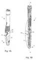
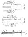
- the feedback devicecomprises in the first place (see Figures 1A and 1B a cap 2 which covers its distal end 4.
- a cap 2which covers its distal end 4.
- injection 1we discover (see Figures 2A and 2B ) a sheath 6 extended at its distal end by a retaining element 8, these two elements protruding from the main body 10 of the retro-injection device 1.
- the retaining element 8is secured to a secondary body 12 which extends coaxially inside the main body 10.
- the retro-injection operationcan not begin before a jumper 14 which presents (see FIG. Figure 2C ) at its base a pin 16 by which it is engaged in corresponding holes respectively in the main body 10, the sheath 6 and the secondary body 12.
- the main body 10, the sheath 6 and the secondary body 12are coupled with each other, which makes any axial displacement of these elements relative to each other impossible and thus prevents the back-injection.
- the cap 2has a notch 18 by which it covers the arms 20 of the rider 14 which follow the substantially circular shape of the distal end of the main body 10. It is thus impossible to remove the jumper 14 before having removed the cap 2, which provides additional security against inadvertent activation of the feedback device 1 according to the invention.
- the retro-injection operation itselfcan begin.
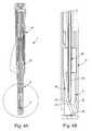
- the practitioneractivates the injection device 1 by pressing its retaining element 8 against the skin of the subject 22.
- the retaining element 8penetrates slightly inside the sheath 6 (see figure 3 ).
- this retaining element 8comprises (see Figures 4A and 4B ) an elastic tongue 24 which, in the rest position, closes by an end portion 25 inclined towards the inside of the volume of the retaining element 8 the through hole 26 of a hollow needle 28 arranged coaxially inside the secondary body 12 and in which is engaged the implant 30 to be administered to the subject.
- the sheath 6has on the inner periphery of its distal end two inclined planes 32 which will come to bear on the elastic tongue 24 during the forward movement of the retaining element 8 inside said sheath 6 (see FIG. Figures 5A and 5B ), said tongue 24 will move away from its rest position and thus release the passage of the needle 28 (see Figures 6A and 6B ).
- the hollow needle 28is thus not obliged to clear its path by pushing its bevel 33 into an element of the device 1, which makes it possible not to damage said bevel 33 and to avoid the risk of injecting chips of plastic material in the skin 22 of the subject.
- the inclined planes 32serve to index the position of the retaining element 8 inside the sheath 6.
- the retaining element 8has a rib slightly projecting from its surface. outer cylindrical and which slides between said two inclined planes 32.
- the main body 10has on the inner periphery of its distal end at least one and, preferably, two recesses diametrically opposite and in which are projecting two substantially V-shaped elastic arms 38 provided at the proximal end of the sheath 6. (see Figures 7A and 7B ). These two arms 38 have two functions. The first of these functions is to allow the temporary immobilization of said sheath 6 relative to said main body 10 in the storage position of the retro-injection device 1 according to the invention.
- the secondary body 12has on its outer periphery two diametrically opposed flat portions 39 which, in the storage position, hold the resilient arms 38 of the sheath 6 in recesses 36 formed in the inner surface of the main body 10 (see Figure 8B ).
- the elastic arms 38each have at their base a lug 42 which protrudes into the corresponding housing 36. Therefore, when the retro-injection device 1 is pressed by the distal end of its retaining element 8 against the skin 22 of the subject, said retaining element 8, integral with the secondary body 12, slightly raises the latter inside the main body 10, so that inclined planes 40 formed on the outer periphery of said secondary body 12 move away from the elastic arms 38 which are thus free to flex (see Figure 8C ). The lugs 42 then emerge from their position engaged in the housings 36, so that the sheath 6 is uncoupled from the main body 10 and is allowed to go up inside thereof. Note also that the sheath 6 has two frustoconical flanges 43 by which it abuts against an inner shoulder 45 provided at the distal end of the main body 10.
- the second function of the elastic arms 38is to allow the final locking of the secondary body 12 on the sheath 6 as will be described later.
- the retaining element 8comprises an elastic tongue 46 over which the needle 28 passes and which, in the storage position of the retro-injection device 1, is bent towards the inside of the volume of the retaining element 8 by a lug 48 provided on the inner surface of the sheath 6.
- the needle 28is thus slightly spaced from its general direction of advance along the longitudinal axis of symmetry XX of the retro-injection device 1 so that, if the implant partially slides out of the needle 28 under the effect of its weight, it will abut against the distal end of the retaining element 8, which will prevent it from falling.
- the retaining element 8penetrates slightly inside the sheath 6, so that the lug 48 moves away from the tongue 46 which covers its rest position and which allows the needle 28 to align with the longitudinal axis of symmetry XX of the injection device 1 and the through hole 26.
- an arch 50may be provided at the end tongue 46 for better axial guidance of the hollow needle 28.
- the position of the secondary body 12is indexed with respect to the sheath 6 by means of its two inclined planes 40 which must be slid into the recesses of the V-shaped elastic arms 38.
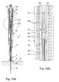
- itis indexed by at least one and, preferably, two pins 52 (see Figure 7A ) diametrically opposed which are engaged in the longer grooves 54 of two cam tracks 56 formed in the inner side wall of the main body 10 (see figure 12A ).
- the hollow needle 28is worn (see figure 10A ) by a substantially cylindrical holding part called base and generally designated by the general reference numeral 58.
- the proximal end of the base 58is cut into crenellations which form tabs 60 provided at their base bulges 62. These bulges 62 protrude into corresponding openings 64 formed at the proximal end of the main body 10 for locking the base 58 on said main body 10 (see FIG. figure 10B ).
- the base 58is capped by an end cap 66 (see figure 11A ) which has at its base a notch 68 in which is housed an index 70 provided on the main body 10.
- the base 58Towards its distal end, the base 58 comprises a tube portion 72 which defines a through opening 74 for holding friction and / or bonding of the hollow needle 28 and which is connected to the hollow cylindrical body 59 of the base 58 by one and, preferably, two ribs 76 diametrically opposed.
- a cylindrical sleeve 78extends coaxially within the end cap 66.
- the cap 66also includes a bar 84 which extends in a diameter inside the cap. sleeve 78 and on which is fixed by pinching the head 86 of a piston rod 88 slidable within the hollow needle 28 to hold in place the implant 30 at the time of the retro-injection (see figure 11C ).
- the main body 10has on its inner surface at least one and, preferably, two cam paths 56 diametrically opposed and each formed of two longitudinal rectilinear grooves 54 and 90, one of which 54 , is longer than the other 90.
- a collar 92serves in particular as a support piece for a spring 94 (see Figures 12A and 12B ).
- this spring 94In the storage position of the feedback device 1, this spring 94 is slightly prestressed. As will be seen below, this spring 94 will compress further as soon as one begins to support said retro-injection device 1 against the skin 22 of the subject and will again be allowed to relax at the time of the retro-injection. injection proper.
- the collar 92is slidable inside the main body 10 and has for this purpose at its periphery two diametrically opposite lugs 96 which are able to cooperate each with one or other of the two grooves 54, 90 of the paths as a function of the angular position of said collar 92 within said main body 10 (see FIG. Figures 13A and 13B ).
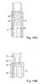
- This positionis controlled by the secondary body 12 which has for this purpose a cam surface 98 (see Figures 14A to 14C ) against which the collar 92 abuts by a cam path 100 formed on its inner surface.
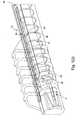
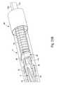
- the secondary body 12is a hollow body of generally cylindrical shape provided with two diametrically opposed rectilinear slots 102 and which extend from the proximal end of said secondary body 12 to a height h above the distal end 4 of the retro-injection device 1. As will be seen below, this height h determines the depth of penetration of the hollow needle 28 into the skin 22 of the subject. Indeed, the slots 102 materialize two portions of tube 12a and 12b which pass on either side of the tube portion 72 in which is fixed the hollow needle 28 and which penetrate inside the hollow cylindrical body 59 of the base 58 (see figure 15 ).
- this base 58is free to slide along the secondary body 12 until the ribs 76 through which the tube portion 72 is connected to the body 59 of said base 58 come into abutment at the bottom of the slots 102.
- the two tube portions 12a, 12bpass on either side of the bar 84 and penetrate inside the sleeve 78 from which they emerge through the proximal end 103 of the retro-injection device 1.
- the two portions 12a tube, 12b of the secondary body 12are therefore able to gradually emerge from the main body 10 as the hollow needle 28 enters the skin 22 of the subject.
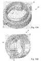
- the secondary body 12comprises on the inner face of the two tube portions 12a, 12b locking means 104, for example in the form of two beads (see Figure 16A and 16B ).
- locking means 104have the function of decoupling the head 86 from the piston rod 88 of the main body 10 and of coupling it with the secondary body 12.
- the head 86 of the piston rod 88is pinched by means of two elastic clips 106 on the bar 84 which extends diametrically inside the sleeve 78 of the end cap 66.
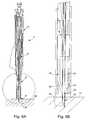
- the two tube portions 12a, 12b of the secondary body 12gradually emerge from the main body 10, so that the two beads 104 meet the head 86 of the piston rod 88 and eventually pass behind it. elastically deforming (see Figures 17A and 17B ).
- the piston rod 88does not accompany this recoil movement (see Figures 18A and 18B ). Indeed, its head 86 being retained by the beads 104, it is decoupled from the main body 10 (more precisely the end cap 66) and remains stationary, thereby gradually penetrating into the hollow needle 28 as the latter exits the skin 22 of the subject.
- the implant 30thus emerges from the needle 28, held in position at the right depth in the skin 22 by the distal end of the piston rod 88 which bears against said implant 30.
- the proximal end of the base 58comes to meet the head 86 of the piston rod 88.
- the locking means 104 carried by the secondary body 12will protrude from the head 86 of the piston rod 88 by deforming elastically, thus decoupling the head 86 from the piston rod 88 of the secondary body 12 and coupling it again with the main body 10 to allow continued downward movement of the secondary body 12 and thus allow it to cover the needle 28 and the piston rod 88 (see Figures 19A and 19B ).
- the spring 94is in abutment at its distal end against the collar 92 and at its proximal end against the base 58.
- the secondary body 12carries with it the collar 92 which is supported by its cam path 100 against the cam surface 98 of said secondary body 12.
- the lugs 96 of the collar 92slide along the shortest grooves 90 of the two cam tracks 56 formed in the inner wall of the main body 10.
- the thrust force of the spring 94is transmitted to the secondary body 12 via the collar 92. Simultaneously, the secondary body 12 pushes forward, in the output direction of the main body 10, the sheath 6.
- the secondary body 12transmits its thrust force to the sheath 6 through its inclined planes 40 which abut against the bottom of the V-shaped elastic arms 38 Indeed, the latter, bearing against the inner wall of the main body 10, are not allowed to depart.
- the movement of the sheath 6 out of the main body 10stops when said sheath 6 abuts by its frustoconical flanges 43 against the inner shoulder 45 provided at the distal end of the main body 10.
- This additional displacementis used to drop the base of the V-shaped elastic arms 38 in two slots 108 diametrically opposed between the feet of the inclined planes 40 and two longitudinal edges 110 (see figure 22C ).
- the secondary body 12is locked on the sheath 6 which itself is locked on the main body 10, so that the retro-injection device 1 according to the invention is completely locked after use.
- the retaining element 8pushes back the secondary body 12 which it is integral, which allows the inclined planes 40 formed on the secondary body 12 to move away from the elastic arms 38 which are thus allowed to flex.
- the lugs 42 provided at the base of these elastic arms 38are disengaged from their position in engagement with the housings 36 provided at the distal end of the body 10, so that the sheath 6 is uncoupled from said main body 10.
- the retaining element 8continues to penetrate inside the sheath 6 until it abuts against the distal end of the sheath 6. the latter.
- the retaining element 8then exerts a thrust on the sheath 6 on the one hand, and on the secondary body 12 on the other hand, so that these two parts begin to retract inside the main body 10. note that during this movement, the relative position of the sheath 6 relative to the secondary body 12 remains unchanged. The sheath 6 and the secondary body 12 retracting, the hollow needle 28 gradually emerges from the main body 10 and penetrates into the skin 22 of the subject ( figure 23D ).
- the recoil movement of the secondary body 12is authorized by the fact that the two tube portions 12a, 12b from which it is formed exit through the proximal end of the retro-injection device 1 by sliding inside the sleeve 78, passing on either side of the bar 84 which extends radially inside said socket 78 ( figure 23 E ).
- the secondary body 12comes to meet the head 86 of the piston rod 88 which is initially coupled with the main body 10 via its two elastic clips 106 clamped on the bar 84 of the sleeve 78.
- the two beads 104 formed on the inner face of the tube portions 12a, 12bthus reach the head 86 of the piston rod 88 and pass behind it by deforming elastically.
- the secondary body 12carries with it the collar 92 which slides by its lugs 96 along the shortest grooves 90 of the cam paths 56 formed diametrically opposite in the inner wall of said main body 10.
- the spring 94resting against the collar 92 which goes up inside the main body 10 and against the base 58 which is fixed, compresses.
- the beads 104retain the head 86 of the piston rod 88 which separates from the main body 10 and is coupled with said secondary body 12.
- the piston rod 88thus remains immobile, gradually penetrating the needle hollow 28 to hold the implant 30 in position at the proper depth in the skin 22 of the subject.
- the advance movement of the sheath 6is interrupted when it abuts by its two frustoconical flanges 43 against the inner shoulder 45 provided at the distal end of the main body 10.
- the secondary body 12slides by its inclined planes 40 under the elastic arms 38. The latter are housed in the two slots 108 provided behind said inclined planes 40.
- the secondary body 12is thus locked on the sheath 6 which itself locks on the main body 10 by by means of its resilient arms 38 whose lugs 42 engage in the housings 36 of the main body 10.
- the retro-injection device 1 according to the inventionis thus completely locked and irreversibly ( figure 23G ).
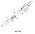
- the secondary bodyhere designated by the reference numeral 114, comprises only a single portion of tube 114a which corresponds substantially to half of the cylindrical envelope in which inscribed said secondary body 114 (see Figures 24A and 24B ).
- a window 116In this portion of tube 114a is defined a window 116 in which extends a longitudinal elastic arm 118 terminated at its free end by a bulge 120 oriented on the inside of said tube 114a.
- the base of the hollow needle 28As for the base of the hollow needle 28 (see Figures 25A and 25B ), designated here by the reference 122, it essentially comprises a tube portion 124 which defines a through opening 126 for maintaining friction and / or gluing of said needle 28 and which is extended by a rectilinear gutter 128 which presents a U-shaped cross section adapted to cooperate with the shape of the secondary body 114.
- the body 130 of the base 122is for its part formed by a cylinder portion 132 which is attached to the opposite vertical flanks 128a of the gutter 128 so as to define an annular passage 134 in which the tube portion 114a of the secondary body 114 can slide (see FIG. figure 32 ).
- a window 136is provided whose role will be described below.
- the body 130 of the base 122terminates in a button 138 comprising two bulges 140 intended to protrude into two corresponding openings 142 formed at the proximal end of the main body 144 for the immobilization of said base 122 on said main body 144.
- the end cap 66 provided in the first embodimentis no longer necessary.
- a notch 146located in the same plane and in the extension of the window 136.
- the head 148 of the piston rod 88comprises a lug 150 which, in the storage position of the retro-injection device 1 according to the invention, projects into the notch 146 of the button 138, which ensures the coupling between said rod. piston 88 and the main body 144 via the base 122 (see figure 26B ).
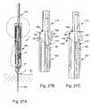
- the lug 150 of the head 148 of the piston rod 88is connected via an inclined plane 152 to a heel 154. As the hollow needle 28 penetrates into the skin 22 of the subject, the secondary body 114 goes back inside the main body 144 by sliding along the base 122 (see Figure 27B ).
- the head 148 of the piston rod 88slides by its heel 154 on the bulge 120 of the elastic arm 118 which deviates from its position. rest. Finally, the head 148 exceeds the bulge 120 and its heel 154 falls into the window 116. At this time, the head 148 of the piston rod 88 is coupled on the one hand with the main body 144 and secondly with the secondary body 114 (see figure 27C ). The collar 92, meanwhile, changes the groove, and the spring 94 is compressed to its maximum.
- the spring 94relaxes and the secondary body 114 slides again along the base 122 but in the direction of the output of the main body 144 this time.
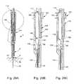
- the lug 150 of the head 148 of the piston rod 88retained by the bulge 120 (see figure 28B ), disengages from the main body 144 and slides along the bottom 128b of the channel 128 until it is next to the window 136 (see Figures 29B and 29C ).
- the piston rod 88expands and the lug 150 enters said window 136, its heel 154 separating from the bulge 120.
- the piston rod 88is thus again coupled with the base 122, that is to say with the main body 144, which allows the secondary body 114 to travel the distance necessary for the complete removal of the needle 28 from the subject's skin 22 and the protection of the subject inside the feedback device.
- injection 1according to the invention (see figure 30 ).
- the implant 30has been maintained at the proper depth in the skin 22 of the subject, and it remains to finish removing the needle 28 and the piston rod 88 from the skin 22.
- the piston rod 88again secured to the main body 144, is withdrawn concomitantly with the needle 28.
- the present inventionis not limited to the embodiments which have just been described and that various simple modifications and variants can be envisaged by those skilled in the art without departing from the scope of the invention as defined. by the appended claims.
- the springinstead of being substantially relaxed in the storage position of the retro-injection device, either on the contrary compressed and relaxes during the return of the secondary body out of the main body.
- the two tube portions 12a, 12bcan be held together by snapping on a cap 156 throughout the use of the retro-injection device 1 according to the invention.
- the two tube portions 12a, 12beach have a bulge 158 which defines a hooking surface 160 on an inner rim 162 of the cap 156.
- the cap 156also serves to ensure the temporary coupling between the head 86 of the piston rod 88 and the main body 10 in storage position of the retro-injection device 1.
- the head 86 of the piston rod 88is in the form of a pair of clips 163 past through a central sleeve 164 formed inside the end cap 66 and each having a bulge 166 defining a gripping surface 168 on the sleeve 164. In the storage position, the clips 163 are kept apart one of the other by a conical tip 170 which stands on the lower surface of the cap 156.
- the secondary body 12When the retro-injection device 1 is activated, the secondary body 12 gradually leaves the main body 10, so that the tip 170 disengages These clips are then allowed to move towards each other and can slide inside the socket 164, thus allowing the decoupling of the head 88 of the piston rod 86 from the main body. 10.
Landscapes
- Health & Medical Sciences (AREA)
- Engineering & Computer Science (AREA)
- Anesthesiology (AREA)
- Biomedical Technology (AREA)
- Heart & Thoracic Surgery (AREA)
- Hematology (AREA)
- Life Sciences & Earth Sciences (AREA)
- Animal Behavior & Ethology (AREA)
- General Health & Medical Sciences (AREA)
- Public Health (AREA)
- Veterinary Medicine (AREA)
- Dermatology (AREA)
- Medical Informatics (AREA)
- Infusion, Injection, And Reservoir Apparatuses (AREA)
- Media Introduction/Drainage Providing Device (AREA)
Description
Translated fromFrenchLa présente invention concerne un dispositif d'injection et, en particulier, un dispositif pour l'injection intra-musculaire ou sous-cutanée d'un principe actif pharmaceutique à l'état solide ou semi-solide habituellement appelé implant. Plus généralement, l'invention s'applique à l'injection d'un corps solide à destination humaine ou encore animale comme par exemple des puces électroniques utilisées pour l'identification d'un être vivant.The present invention relates to an injection device and, in particular, a device for intramuscular or subcutaneous injection of a pharmaceutical active ingredient in the solid state or semi-solid usually called implant. More generally, the invention applies to the injection of a solid body for human or animal purposes such as electronic chips used for the identification of a living being.
Les dispositifs de rétro-injection d'un implant du genre auquel la présente invention s'intéresse comprennent classiquement un corps principal creux auquel est fixée une aiguille creuse dans laquelle est introduit l'implant à injecter. Un corps secondaire, disposé coaxialement à l'intérieur du corps principal, entoure l'aiguille dans laquelle est susceptible de coulisser coaxialement une tige de piston, Cette tige de piston a pour but d'assurer que l'implant est déposé à la bonne profondeur dans les tissus du sujet. Lorsque l'on presse un tel dispositif de rétro-injection contre les tissus du sujet, le corps principal se met à coulisser le long du corps secondaire depuis une position proximale vers une position distale pour permettre à l'aiguille de pénétrer dans les tissus du sujet. Le déplacement du corps principal s'accompagne d'un déplacement simultané de la tige de piston qui, lors du retrait de l'aiguille hors des tissus du sujet, demeure fixe relativement à cette aiguille pour permettre de maintenir l'implant à la profondeur requise dans les tissus du sujet.The retro-injection devices of an implant of the kind to which the present invention is concerned conventionally comprise a hollow main body to which is fixed a hollow needle into which the implant to be injected. A secondary body, coaxially disposed within the main body, surrounds the needle in which a piston rod is coaxially slidable. This piston rod is intended to ensure that the implant is deposited at the proper depth. in the tissues of the subject. When such a retro-injection device is pressed against the tissues of the subject, the main body begins to slide along the secondary body from a proximal position to a distal position to allow the needle to penetrate the tissues of the subject. subject. The displacement of the main body is accompanied by a simultaneous movement of the piston rod which, when the needle is withdrawn from the tissue of the subject, remains fixed relative to this needle to maintain the implant at the required depth in the tissues of the subject.
Le mode d'emploi d'un tel dispositif de rétro-injection est le suivant. En tenant d'une main le dispositif de rétro-injection par son corps principal, le praticien vient appuyer l'extrémité distale du corps secondaire contre la peau du sujet. Lorsque le dispositif de rétro-injection est convenablement disposé, le praticien exerce une poussée sur le corps principal. Sous l'effet de cette poussée, le corps principal se met à coulisser axialement le long du corps secondaire, permettant à l'aiguille qui est solidaire dudit corps principal de pénétrer dans la peau du sujet. Dans le même temps, le corps principal entraîne la tige de piston dont la position relativement à l'aiguille et à l'implant reste ainsi inchangée. C'est au moment où l'aiguille a pénétré au maximum dans les tissus du sujet que survient l'opération de rétro-injection proprement dite de l'implant. En effet, le praticien, dans un geste qui n'est pas sans rappeler celui d'une injection classique va, de sa main gauche s'il est droitier, maintenir le dispositif de rétro-injection contre la peau du sujet afin de minimiser les mouvements de l'aiguille et déplacer son autre main de manière à maintenir le corps secondaire contre la peau via son pouce qui appuie sur un bouton prévu à l'extrémité proximale du corps secondaire tandis que, de son index et de son majeur, il va commander le retour du corps principal vers sa position proximale en se servant d'un appuie-doigts dont est muni ledit corps principal. Au cours de ce geste, l'aiguille sort progressivement hors des tissus du sujet. La tige de piston n'accompagne toutefois pas ce mouvement de recul du corps principal. En effet, retenue par le corps secondaire, elle est découplée dudit corps principal et reste immobile, pénétrant ainsi progressivement dans l'aiguille creuse au fur et à mesure que cette dernière sort de la peau. L'implant émerge ainsi de l'aiguille, maintenu en position à la bonne profondeur dans la peau par l'extrémité distale de la tige de piston qui est en appui contre ledit implant. La tige de piston est alors découplée du corps secondaire et à nouveau couplée avec le corps principal de manière que l'aiguille et la tige de piston terminent ensemble le mouvement de rétro-injection dans une position dans laquelle ils sont protégés par le corps secondaire.The use of such a retro-injection device is as follows. By holding the retro-injection device in one hand with its main body, the practitioner presses the distal end of the secondary body against the subject's skin. When the retro-injection device is properly disposed, the practitioner pushes on the main body. Under the effect of this thrust, the main body begins to slide axially along the secondary body, allowing the needle which is secured to said main body to penetrate into the skin of the subject. At the same time, the main body drives the piston rod whose position relative to the needle and the implant thus remains unchanged. It is at the moment when the needle has penetrated as far as possible into the tissues of the subject that the actual retro-injection operation of the implant occurs. Indeed, the practitioner, in a gesture that is not unlike that of a conventional injection goes, with his left hand if it is right-handed, maintain the device of retro-injection against the skin of the subject to minimize the movements of the needle and move his other hand so as to maintain the secondary body against the skin via his thumb pressing a button provided at the proximal end of the secondary body while, his forefinger and middle finger, he goes controlling the return of the main body to its proximal position by using a fingerrest which is provided with said main body. During this gesture, the needle progressively leaves the tissue of the subject. The piston rod does not, however, accompany this recoil movement of the main body. Indeed, retained by the secondary body, it is decoupled from said main body and remains immobile, thereby gradually penetrating into the hollow needle as it leaves the skin. The implant thus emerges from the needle, held in position at the right depth in the skin by the distal end of the piston rod which bears against said implant. The piston rod is then decoupled from the secondary body and again coupled with the main body so that the needle and the piston rod together terminate the feedback movement in a position in which they are protected by the secondary body.
A l'usage, on s'est rendu compte que l'utilisation d'un dispositif de rétro-injection du genre décrit ci-dessus n'était pas toujours commode et souvent mal comprise par les praticiens. En effet, bon nombre de praticiens ont pensé que le geste était terminé une fois qu'ils avaient fait pénétrer l'aiguille au plus profond dans les tissus du sujet, omettant de procéder à l'opération de rétro-injection qui seule permet de déposer l'implant dans les tissus du sujet. D'autres praticiens ont tenté d'effectuer le geste de rétro-injection en plaçant leur pouce sur le bouton du corps secondaire et en passant leur index et leur majeur sous l'appuie-doigts comme indiqué. Toutefois, ces praticiens maintenaient fermement le corps principal de leur autre main, ce qui rendait impossible le retour dudit corps principal vers sa position proximale et donc la sortie de l'aiguille hors des tissus du sujet. Plus généralement, il a été jugé peu commode et source de douleurs pour le sujet de devoir tenir le dispositif de rétro-injection d'une main pour l'appuyer contre la peau du sujet et y enfoncer l'aiguille, puis de devoir lâcher ledit dispositif pour, de la même main, procéder au geste de rétro-injection.In use, it has been realized that the use of a feedback device of the kind described above is not always convenient and often misunderstood by practitioners. Indeed, many practitioners thought that the gesture was finished once they had penetrated the needle deep into the tissues of the subject, failing to carry out the operation of retro-injection which alone allows to deposit the implant in the tissues of the subject. Other practitioners attempted to perform the reverse injection procedure by placing their thumb on the secondary body button and passing their index finger and middle finger under the finger rest as shown. However, these practitioners held firmly the main body of their other hand, which made it impossible to return the main body to its proximal position and thus the exit of the needle out of the tissue of the subject. More generally, it has been considered inconvenient and painful for the subject to have to hold the retro-injection device with one hand to press against the subject's skin and to insert the needle therein, and then to release device for, in the same hand, proceed to the gesture of retro-injection.
La présente invention a pour but de remédier aux inconvénients susmentionnés ainsi qu'à d'autres encore en procurant un dispositif pour la rétro-injection d'un implant qui permet notamment de simplifier le plus possible le geste d'injection de l'implant sous la peau du sujet.The present invention aims to overcome the aforementioned drawbacks as well as others by providing a device for the retro-injection of an implant that allows in particular to simplify as much as possible the injection of the implant under action. the skin of the subject.
A cet effet, la présente invention concerne un dispositif pour la rétro-injection d'un implant dans la peau d'un sujet, ce dispositif comprenant un corps principal creux auquel est fixée une aiguille creuse dans laquelle est introduit l'implant, un corps secondaire disposé coaxialement à l'intérieur du corps principal et entourant l'aiguille, et une tige de piston susceptible de coulisser coaxialement à l'intérieur de ladite aiguille creuse et dont la position relativement à cette aiguille reste inchangée lorsque le dispositif de rétro-injection est pressé contre la peau du sujet pour permettre à l'aiguille de pénétrer dans la peau dudit sujet et que le corps secondaire se rétracte à l'intérieur du corps principal, la tige de piston s'enfonçant à l'intérieur de l'aiguille creuse pour maintenir l'implant à la profondeur requise dans la peau du sujet pendant le retrait de l'aiguille creuse hors de la peau du sujet, retrait au cours duquel le corps secondaire sort du corps principal, caractérisé en ce qu'il comprend des moyens de rappel élastiques du corps secondaire hors du corps principal.For this purpose, the present invention relates to a device for the retro-injection of an implant into the skin of a subject, this device comprising a hollow main body to which is fixed a hollow needle into which the implant is inserted, a body secondary body disposed coaxially inside the main body and surrounding the needle, and a piston rod slidable coaxially within said hollow needle and whose position relative to this needle remains unchanged when the retro-injection device is pressed against the subject's skin to allow the needle to penetrate the skin of said subject and the secondary body retracts within the main body, the piston rod sinking to the interior of the hollow needle to hold the implant to the required depth in the subject's skin during removal of the hollow needle from the subject's skin, withdrawal during which the secondary body exits the main body, characterized in it comprises elastic return means of the secondary body out of the main body.
Grâce à ces caractéristiques, la présente invention procure un dispositif pour la rétro-injection d'un implant qu'il suffit de presser contre la peau du sujet jusque tant que l'aiguille ait complètement pénétré dans la peau, le corps secondaire sortant ensuite automatiquement du corps principal pour venir recouvrir l'aiguille au fur et à mesure que l'on éloigne le dispositif de rétro-injection de la peau du sujet et que l'opération d'injection de l'implant s'effectue. L'opération d'injection de l'implant est donc entièrement automatisée sitôt l'aiguille insérée dans les tissus, ce qui la rend aussi simple que possible et permet notamment d'éliminer le geste de rétro-injection relativement compliqué auquel on devait procéder avec les dispositifs de l'art antérieur. Par ailleurs, il n'est pas nécessaire de changer la manière dont on tient le dispositif selon l'invention au cours de l'opération de rétro-injection de l'implant, ce qui facilite également le travail du praticien. On notera également que l'aiguille creuse dans laquelle est introduit l'implant est coiffée par le corps secondaire avant et après injection, ce qui évite tout risque d'éraflure et de contamination de l'aiguille et du praticien.Thanks to these features, the present invention provides a device for the retro-injection of an implant that suffices to press against the skin of the subject until the needle has completely penetrated the skin, the secondary body then exiting automatically. the main body to cover the needle as the retrorejection device is moved away from the subject's skin and the injection operation of the implant takes place. The injection operation of the implant is therefore fully automated as soon as the needle inserted into the tissue, which makes it as simple as possible and in particular eliminates the relatively complicated retro-injection gesture that was to be performed with the devices of the prior art. Furthermore, it is not necessary to change the manner in which the device according to the invention is held during the implant injection back-injection operation, which also facilitates the work of the practitioner. It should also be noted that the hollow needle into which the implant is inserted is capped by the secondary body before and after injection, which avoids any risk of scratching and contamination of the needle and the practitioner.
Selon une caractéristique complémentaire de l'invention, le dispositif de rétro-injection comprend un élément de retenue destiné à empêcher l'implant de tomber avant utilisation dudit dispositif.According to an additional characteristic of the invention, the retro-injection device comprises a retaining element intended to prevent the implant from falling before use of said device.
Selon une première variante de réalisation, l'élément de retenue comprend une languette élastique qui, en position de repos, obture par une partie terminale inclinée vers l'intérieur du volume de l'élément de retenue le trou de passage de l'aiguille creuse et qui, lorsque le dispositif de rétro-injection est appuyé contre la peau du sujet, s'écarte pour libérer le passage de ladite aiguille creuse.According to a first variant embodiment, the retaining element comprises an elastic tongue which, in the rest position, closes the hole through which the hollow needle passes through an end portion inclined towards the inside of the volume of the retaining element. and which, when the feedback device is pressed against the subject's skin, deviates to release the passage of said hollow needle.
Selon une seconde variante de réalisation, l'élément de retenue comprend une languette élastique au-dessus de laquelle passe l'aiguille creuse et qui, en position de stockage du dispositif de rétro-injection, est fléchie vers l'intérieur du volume dudit élément de retenue, de sorte que l'aiguille est écartée de sa direction générale d'avance, la languette élastique recouvrant sa position de repos dans laquelle elle autorise ladite aiguille à se réaligner et à avancer lorsque l'on presse ledit dispositif de rétro-injection contre la peau du sujet.According to a second variant embodiment, the retaining element comprises an elastic tongue over which the hollow needle passes and which, in the storage position of the retro-injection device, is flexed towards the inside of the volume of said element. retaining, so that the needle is spaced from its general direction of advance, the elastic tongue covering its rest position in which it allows said needle to realign and advance when pressing said retro-injection device against the skin of the subject.
Ces deux variantes de réalisation de l'élément de retenue de l'implant possèdent un avantage commun qui réside dans le fait que l'aiguille creuse n'a pas à venir pousser par son biseau contre un élément du dispositif d'injection pour se frayer un chemin vers la sortie dudit dispositif. Le biseau de l'aiguille ne risque donc pas de s'endommager et les risques d'injecter dans la peau du sujet des copeaux de la matière plastique dont est fait le dispositif d'injection sont évités.These two embodiments of the implant retaining element have a common advantage that lies in the fact that the hollow needle does not have to come to push by its bevel against an element of the injection device to spawn. a path to the output of said device. The bevel of the needle is not likely to be damaged and the risk of injecting into the skin of the subject of the chips of the plastic material which is made the injection device are avoided.
Selon une autre caractéristique de l'invention, le dispositif de rétro-injection comprend en outre une gaine qui coopère avec le corps secondaire pour permettre le verrouillage irréversible du dispositif de rétro-injection après utilisation. Plus précisément, le corps secondaire se verrouille sur la gaine qui elle-même se verrouille sur le corps principal.According to another characteristic of the invention, the feedback device further comprises a sheath which cooperates with the secondary body to allow the irreversible locking of the retro-injection device after use. More specifically, the secondary body locks on the sheath which itself locks on the main body.
Le dispositif de rétro-injection est ainsi totalement verrouillé après utilisation, ce qui rend toute réutilisation ultérieure de ce dispositif impossible et surtout élimine tout risque pour le praticien de se piquer avec l'aiguille souillée.The retro-injection device is thus fully locked after use, which makes any subsequent reuse of this device impossible and above all eliminates any risk for the practitioner to prick with the dirty needle.
Selon encore une autre caractéristique de l'invention, la gaine assure également le verrouillage temporaire du dispositif de rétro-injection avant utilisation.According to yet another characteristic of the invention, the sheath also ensures the temporary locking of the retro-injection device before use.
Le dispositif de rétro-injection n'est activé qu'au moment où on le presse contre la peau du sujet, ce qui ôte toute possibilité au praticien d'accéder à l'aiguille avant de procéder à l'injection et de risquer de souiller l'aiguille en se piquant.The retro-injection device is activated only when it is pressed against the skin of the subject, which removes any possibility for the practitioner to access the needle before injecting and risk contaminating the needle by pricking itself.
Selon encore une autre caractéristique de l'invention, les moyens de rappel élastiques comprennent un ressort qui est en appui à l'une de ses extrémités contre un collier lui-même en appui sur le corps secondaire, et qui est en appui à son autre extrémité contre une embase qui porte l'aiguille creuse et qui est solidaire du corps principal.According to yet another characteristic of the invention, the elastic return means comprise a spring which is supported at one of its ends against a collar itself bearing on the secondary body, and which is in support of its other end against a base which carries the hollow needle and which is secured to the main body.
Lorsqu'on enfonce l'aiguille dans la peau du sujet, le collier remonte en coulissant axialement à l'intérieur du corps principal, de sorte que le ressort se comprime. Ensuite, arrivé à un point de rebroussement qui correspond au point de pénétration maximum de l'aiguille dans la peau, le collier pivote et coulisse à nouveau en sens inverse dans le corps principal, ce qui autorise le ressort à se détendre. Ainsi, à l'exception du collier, toutes les pièces mobiles du dispositif de rétro-injection selon l'invention ne se déplacent qu'axialement, ce qui permet de garantir un fonctionnement fiable du dispositif. En effet, lorsqu'on presse le dispositif de rétro-injection contre la peau du sujet, cela génère des forces de frottement qui pourraient gêner le bon fonctionnement du dispositif si la pièce au contact de la peau devait effectuer un mouvement de pivotement.When the needle is pushed into the subject's skin, the collar rises axially sliding inside the main body so that the spring compresses. Then, arrived at a cusp that corresponds to the point of maximum penetration of the needle into the skin, the collar pivots and slides back in the opposite direction in the main body, which allows the spring to relax. Thus, with the exception of the collar, all the moving parts of the retro-injection device according to the invention move only axially, which ensures a reliable operation of the device. Indeed, when the retro-injection device is pressed against the skin of the subject, it generates friction forces that could hinder the proper functioning of the device if the piece in contact with the skin had to perform a pivoting movement.
Selon une première variante de réalisation, le corps secondaire est un corps creux de forme sensiblement cylindrique pourvu de deux fentes rectilignes diamétralement opposées qui s'étendent depuis l'extrémité proximale dudit corps secondaire jusqu'à une hauteur déterminée au-dessus de l'extrémité distale du dispositif de rétro-injection, ces fentes matérialisant deux portions de tube.According to a first variant embodiment, the secondary body is a hollow body of substantially cylindrical shape provided with two straight slots diametrically opposed which extend from the proximal end of said secondary body to a predetermined height above the distal end of the retro-injection device, these slots materializing two portions of tube.
Selon une seconde variante de réalisation, le corps secondaire comprend une seule portion de tube.According to a second variant embodiment, the secondary body comprises a single portion of tube.
Cette seconde variante de réalisation est préférée à la première dans la mesure où elle permet de s'affranchir des problèmes de tolérance liés à la fabrication des différentes pièces constituant le dispositif de rétro-injection.This second embodiment is preferred over the first, since it makes it possible to overcome the problems of tolerance associated with the manufacture of the various parts constituting the retro-injection device.
D'autres caractéristiques et avantages de la présente invention ressortiront plus clairement de la description détaillée qui suit d'un mode de réalisation du dispositif de rétro-injection selon l'invention, cet exemple étant donné à titre purement illustratif et non limitatif seulement, en liaison avec le dessin annexé sur lequel :
- la
figure 1A est une vue en perspective du dispositif de rétro-injection selon l'invention en position de stockage; - la
figure 1B est une vue en coupe longitudinale du dispositif de rétro-injection représenté à lafigure 1A ; - la
figure 2A est une vue en perspective du dispositif de rétro-injection après retrait du capuchon; - la
figure 2B est une vue en coupe longitudinale du dispositif de rétro-injection représenté à lafigure 2A ; - la
figure 2C est une vue en perspective du cavalier; - la
figure 3 est une vue en coupe longitudinale du dispositif de rétro-injection appuyé contre la peau du sujet; - la
figure 4A est une vue en coupe longitudinale du dispositif de rétro-injection équipé de moyens de retenue de l'implant selon une première variante de réalisation; - la
figure 4B est une vue à plus grande échelle de la zone entourée d'un cercle sur lafigure 4A ; - la
figure 5A est une vue analogue à celle de lafigure 4A , le dispositif de rétro-injection ayant été pressé contre la peau du sujet, les moyens de retenue s'étant écartés pour laisser le passage à l'aiguille; - la
figure 5B est une vue à plus grande échelle de la zone entourée d'un cercle sur lafigure 5A ; - la
figure 6A est une vue analogue à celle de lafigure 5A , l'aiguille étant enfoncée dans la peau du sujet; - la
figure 6B est une vue à plus grande échelle de la zone entourée d'un cercle sur lafigure 6A ; - la
figure 7A est une vue partielle en perspective de la gaine, du corps secondaire et du collier; - la
figure 7B est une vue en coupe longitudinale des pièces représentées à lafigure 7A ; - la
figure 8A est une vue en coupe longitudinale du dispositif de rétro-injection selon l'invention en position de repos; - la
figure 8B est une vue à plus grande échelle de la zone entourée d'un cercle sur lafigure 8A , la gaine étant verrouillée sur le corps principal par l'intermédiaire du corps secondaire; - la
figure 8C est une vue analogue à celle de lafigure 8A , le corps secondaire ayant légèrement pénétré à l'intérieur du corps principal, découplant ainsi la gaine dudit corps principal; - la
figure 9A est une vue en coupe longitudinale du dispositif de rétro-injection équipé de moyens de retenue de l'implant selon une seconde variante de réalisation; - la
figure 9B est une vue à plus grande échelle de la zone entourée d'un cercle sur lafigure 9A , les moyens de retenue étant en position de repos, empêchant l'implant de tomber; - la
figure 9C est une vue analogue à celle de lafigure 9B , le dispositif de rétro-injection ayant été pressé contre la peau du sujet et les moyens de retenue autorisant l'aiguille à s'aligner avec son axe général d'avance; - la
figure 10A est une vue en perspective de l'embase servant au maintien de l'aiguille selon un premier mode de réalisation; - la
figure 10B est une vue de détail en perspective de l'extrémité proximale du corps principal; - la
figure 11A est une vue en perspective du capuchon d'extrémité; - la
figure 11B est une vue en coupe longitudinale du dispositif de rétro-injection en position de repos; - la
figure 11C est une vue à plus grande échelle de la zone entourée d'un cercle sur lafigure 11A qui montre le couplage de la tête de la tige de piston sur le capuchon d'extrémité; - la
figure 12A est une vue en perspective du corps principal montrant le chemin de came ménagé dans la paroi intérieure dudit corps principal; - la
figure 12B est une vue partielle en perspective du corps principal sur laquelle sont notamment visibles les deux rainures rectilignes longitudinales du chemin de came; - les
figures 13A et 13B sont des vues en perspective face avant et face arrière du collier; - la
figure 14A est une vue en perspective du corps secondaire selon un premier mode de réalisation; - la
figure 14B est une vue de détail à plus grande échelle de la zone entourée d'un cercle sur lafigure 14A ; - la
figure 14C est une autre vue en perspective du corps secondaire sur laquelle sont notamment visibles les deux portions de tube; - la
figure 15 est une vue partielle en perspective montrant le corps secondaire engagé dans l'embase de l'aiguille; - les
figures 16A et 16B sont des vues schématiques montrant la coopération entre la tête de la tige de piston et les moyens de blocage prévus sur le corps secondaire; - la
figure 17A est une vue en coupe longitudinale du dispositif de rétro-injection au moment où l'aiguille a pénétré au maximum dans la peau du sujet; - la
figure 17B est une vue de détail à plus grande échelle de la zone entourée d'un cercle sur lafigure 17A , la tête dé la tige de piston étant couplée avec le corps principal; - la
figure 18A est une vue en coupe longitudinale du dispositif de rétro-injection pendant la phase d'injection de l'implant dans les tissus du sujet; - la
figure 18B est une vue de détail à plus grande échelle de la zone entourée d'un cercle sur lafigure 18A , la tête de la tige de piston étant découplée du corps secondaire; - la
figure 19A est une vue en coupe longitudinale du dispositif de rétro-injection après retrait complet de l'aiguille hors des tissus du sujet; - la
figure 19B est une vue à plus grande échelle de la zone entourée d'un cercle sur lafigure 19A , la tête de la tige de piston étant à nouveau couplée avec le corps principal; - les
figures 20A, 20B et 20C sont des vues en coupe longitudinale du dispositif de rétro-injection respectivement avant utilisation, au moment où l'aiguille a pénétré au maximum dans la peau du sujet et après verrouillage final et qui illustrent la coopération entre le ressort et le collier; - la
figure 21A est une vue partielle en perspective du dispositif de rétro-injection montrant le collier juste avant de pivoter; - la
figure 21B est une vue analogue à celle de lafigure 21A montrant le collier après pivotement; - la
figure 21C est une vue partielle en perspective montrant le collier arrivé en butée au fond des rainures les plus longues du chemin de came ménagé dans la paroi intérieure du corps principal; - la
figure 22A est une vue en coupe longitudinale du dispositif de rétro-injection après injection de l'implant dans la peau du sujet; - la
figure 22B est une vue à plus grande échelle de la zone entourée d'un cercle sur lafigure 22A qui montre le corps secondaire juste avant son verrouillage sur la gaine; - la
figure 22C est une vue à plus grande échelle de la zone entourée d'un cercle sur lafigure 22A qui montre le corps secondaire verrouillé sur la gaine qui elle-même est verrouillée sur le corps principal; - les
figures 23A à 23G illustrent les différentes phases de fonctionnement du dispositif de rétro-injection selon l'invention; - la
figure 24A est une vue en perspective et de dessus du corps secondaire selon un second mode de réalisation; - la
figure 24B est une vue en perspective et de dessous du corps secondaire représenté à lafigure 24A ; - les
figures 25A et25B sont des vues en perspective et selon deux angles différents de l'embase de l'aiguille selon un second mode de réalisation; - la
figure 26A est une vue en coupe longitudinale avant utilisation du dispositif de rétro-injection comprenant un corps secondaire selon le second mode de réalisation; - la
figure 26B est une vue de détail à plus grande échelle de la zone entourée d'un cercle sur lafigure 26A ; - la
figure 27A est une vue en coupe longitudinale du dispositif de rétro-injection comprenant un corps secondaire selon le second mode de réalisation au moment où l'aiguille a pénétré au maximum dans les tissus du sujet; - la
figure 27B est une vue à plus grande échelle de la zone entourée d'un cercle sur lafigure 27A juste avant que la tête de la tige de piston ne se couple avec le corps secondaire; - la
figure 27C est une vue analogue à celle de lafigure 27B montrant la tête de la tige de piston couplée à la fois avec le corps principal et avec le corps secondaire; - la
figure 28A est une vue en coupe longitudinale du dispositif de rétro-injection pendant la phase de retrait de l'aiguille hors de la peau du sujet; - la
figure 28B est une vue à plus grande échelle de la zone entourée d'un cercle sur lafigure 28A montrant la tête de la tige de piston solidaire du corps secondaire et glissant par son ergot contre la paroi intérieure du corps principal; - la
figure 29A est une vue en coupe longitudinale du dispositif de rétro-injection sur laquelle l'aiguille est pratiquement retirée de la peau du sujet; - les
figures 29B et 29C sont des vues à plus grande échelle de la zone entourée d'un cercle sur lafigure 29A qui montre comment la tête de la tige de piston se couple à nouveau avec le corps principal; - la
figure 30 est une vue en coupe longitudinale du dispositif de rétro-injection en position verrouillée après injection de l'implant, la tête de la tige de piston étant couplée avec le corps principal; - la
figure 31 est une vue partielle en perspective et en coupe de l'extrémité arrière du dispositif de rétro-injection montrant un autre moyen de couplage de la tête de la tige de piston avec le corps secondaire, et - la
figure 32 est une vue en perspective montrant la coopération entre le corps secondaire et l'embase selon le second mode de réalisation.
- the
Figure 1A is a perspective view of the retro-injection device according to the invention in storage position; - the
Figure 1B is a longitudinal sectional view of the retro-injection device shown in FIG.Figure 1A ; - the
Figure 2A is a perspective view of the retro-injection device after removal of the cap; - the
Figure 2B is a longitudinal sectional view of the retro-injection device shown in FIG.Figure 2A ; - the
Figure 2C is a perspective view of the rider; - the
figure 3 is a longitudinal sectional view of the retro-injection device pressed against the skin of the subject; - the
Figure 4A is a longitudinal sectional view of the retro-injection device equipped with implant retention means according to a first embodiment; - the
Figure 4B is a larger-scale view of the area surrounded by a circle on theFigure 4A ; - the
Figure 5A is a view similar to that of theFigure 4A , the retro-injection device having been pressed against the skin of the subject, the retaining means having moved apart to allow passage to the needle; - the
Figure 5B is a larger-scale view of the area surrounded by a circle on theFigure 5A ; - the
Figure 6A is a view similar to that of theFigure 5A the needle being sunk into the skin of the subject; - the
Figure 6B is a larger-scale view of the area surrounded by a circle on theFigure 6A ; - the
Figure 7A is a partial perspective view of the sheath, the secondary body and the collar; - the
Figure 7B is a longitudinal sectional view of the parts shown inFigure 7A ; - the
figure 8A is a longitudinal sectional view of the retro-injection device according to the invention in the rest position; - the
Figure 8B is a larger-scale view of the area surrounded by a circle on thefigure 8A the sheath being locked on the main body via the secondary body; - the
Figure 8C is a view similar to that of thefigure 8A , the secondary body having slightly penetrated inside the main body, thus uncoupling the sheath of said main body; - the
Figure 9A is a longitudinal sectional view of the retro-injection device equipped with implant retention means according to a second embodiment; - the
Figure 9B is a larger-scale view of the area surrounded by a circle on theFigure 9A , the retaining means being in the rest position, preventing the implant from falling; - the
Figure 9C is a view similar to that of theFigure 9B the retro-injection device having been pressed against the skin of the subject and the retaining means allowing the needle to align with its general axis of advance; - the
figure 10A is a perspective view of the base for maintaining the needle according to a first embodiment; - the
figure 10B is a perspective detail view of the proximal end of the main body; - the
figure 11A is a perspective view of the end cap; - the
Figure 11B is a longitudinal sectional view of the retro-injection device in the rest position; - the
figure 11C is a larger-scale view of the area surrounded by a circle on thefigure 11A which shows the coupling of the piston rod head to the end cap; - the
figure 12A is a perspective view of the main body showing the cam path formed in the inner wall of said main body; - the
figure 12B is a partial perspective view of the main body on which are in particular visible the two longitudinal rectilinear grooves of the cam path; - the
Figures 13A and 13B are perspective views front and rear face of the collar; - the
figure 14A is a perspective view of the secondary body according to a first embodiment; - the
Figure 14B is a larger-scale detail view of the area surrounded by a circle on thefigure 14A ; - the
figure 14C is another perspective view of the secondary body on which are in particular visible the two tube portions; - the
figure 15 is a partial perspective view showing the secondary body engaged in the base of the needle; - the
Figures 16A and 16B are schematic views showing the cooperation between the head of the piston rod and the locking means provided on the secondary body; - the
Figure 17A is a longitudinal sectional view of the retro-injection device at the moment when the needle has penetrated to the maximum in the skin of the subject; - the
Figure 17B is a larger-scale detail view of the area surrounded by a circle on theFigure 17A the head of the piston rod being coupled with the main body; - the
figure 18A is a longitudinal sectional view of the retro-injection device during the injection phase of the implant into the tissues of the subject; - the
figure 18B is a larger-scale detail view of the area surrounded by a circle on thefigure 18A the head of the piston rod being decoupled from the secondary body; - the
figure 19A is a longitudinal sectional view of the retro-injection device after complete withdrawal of the needle from the tissues of the subject; - the
figure 19B is a larger-scale view of the area surrounded by a circle on thefigure 19A the head of the piston rod being again coupled with the main body; - the
Figures 20A, 20B and 20C are views in longitudinal section of the retro-injection device respectively before use, at the moment when the needle has penetrated to the maximum in the skin of the subject and after final locking and which illustrate the cooperation between the spring and the collar; - the
figure 21A is a partial perspective view of the retro-injection device showing the collar just before pivoting; - the
figure 21B is a view similar to that of thefigure 21A showing the collar after pivoting; - the
figure 21C is a partial perspective view showing the collar abutting the bottom of the longest grooves of the cam path in the inner wall of the main body; - the
figure 22A is a longitudinal sectional view of the retro-injection device after injection of the implant into the skin of the subject; - the
figure 22B is a larger-scale view of the area surrounded by a circle on thefigure 22A which shows the secondary body just before locking on the sheath; - the
figure 22C is a larger-scale view of the area surrounded by a circle on thefigure 22A which shows the secondary body locked on the sheath which itself is locked on the main body; - the
Figures 23A to 23G illustrate the different operating phases of the retro-injection device according to the invention; - the
figure 24A is a perspective view from above of the secondary body according to a second embodiment; - the
figure 24B is a perspective and bottom view of the secondary body shown in FIG.figure 24A ; - the
Figures 25A and25B are views in perspective and at two different angles of the base of the needle according to a second embodiment; - the
figure 26A is a longitudinal sectional view before use of the feedback device comprising a secondary body according to the second embodiment; - the
figure 26B is a larger-scale detail view of the area surrounded by a circle on thefigure 26A ; - the
Figure 27A is a longitudinal sectional view of the retro-injection device comprising a secondary body according to the second embodiment at the moment when the needle has penetrated to the maximum in the tissues of the subject; - the
Figure 27B is a larger-scale view of the area surrounded by a circle on theFigure 27A just before the head of the piston rod couples with the secondary body; - the
figure 27C is a view similar to that of theFigure 27B showing the head of the piston rod coupled with both the main body and the secondary body; - the
figure 28A is a longitudinal sectional view of the retro-injection device during the withdrawal phase of the needle from the skin of the subject; - the
figure 28B is a larger-scale view of the area surrounded by a circle on thefigure 28A showing the head of the piston rod secured to the secondary body and sliding by its lug against the inner wall of the main body; - the
figure 29A is a longitudinal sectional view of the retro-injection device on which the needle is substantially removed from the skin of the subject; - the
Figures 29B and 29C are larger-scale views of the area surrounded by a circle on thefigure 29A which shows how the head of the piston rod couples again with the main body; - the
figure 30 is a longitudinal sectional view of the retro-injection device in the locked position after injection of the implant, the head of the piston rod being coupled with the main body; - the
figure 31 is a partial perspective view in section of the rear end of the retro-injection device showing another means of coupling the head of the piston rod with the secondary body, and - the
figure 32 is a perspective view showing the cooperation between the secondary body and the base according to the second embodiment.
Dans tout ce qui suit, on entendra par extrémité "proximale" l'extrémité située du côté du praticien, et par extrémité "distale" l'extrémité située du côté du sujet auquel l'injection est administrée.In what follows, the term "proximal" end is the end located on the side of the practitioner, and "distal" end the end of the side of the subject to whom the injection is administered.
On commence par sortir le dispositif de rétro-injection selon l'invention de son emballage secondaire (non représenté). Désigné dans son ensemble par la référence numérique générale 1, le dispositif de rétro-injection comprend en premier lieu (voir
L'opération de rétro-injection ne peut débuter avant que l'on ait en outre retiré un cavalier 14 qui présente (voir
Après retrait du capuchon 2 et du cavalier 14, l'opération de rétro-injection proprement dite peut débuter. Pour cela, le praticien active le dispositif d'injection 1 en l'appuyant par son élément de retenue 8 contre la peau du sujet 22. Sous l'effet de cette poussée, l'élément de retenue 8 pénètre légèrement à l'intérieur de la gaine 6 (voir
Le corps principal 10 présente sur le pourtour intérieur de son extrémité distale au moins un et, préférentiellement, deux logements 36 diamétralement opposés et dans lesquels viennent faire saillie deux bras élastiques 38 sensiblement en forme de V prévus à l'extrémité proximale de la gaine 6 (voir
La seconde fonction des bras élastiques 38 est de permettre le verrouillage final du corps secondaire 12 sur la gaine 6 comme il sera décrit ultérieurement.The second function of the
Comme on l'a vu ci-dessus, une première solution envisageable pour retenir l'aiguille creuse 28 et prévenir la chute de l'implant 30 avant injection est de prévoir sur le chemin de ladite aiguille 28 une languette élastique 24 qui, en position de repos, obture le biseau 33 de l'aiguille 28 et qui, en position activée, est écartée du chemin de cette aiguille 28 pour permettre l'avance de cette dernière et le dépôt de l'implant 30 dans les tissus 22 du sujet. Selon une variante préférée (voir
La position du corps secondaire 12 est indexée par rapport à la gaine 6 par le biais de ses deux plans inclinés 40 qui doivent être glissés dans les creux des bras élastiques 38 en forme de V. Quant à la position de la gaine 6 relativement au corps principal 10, elle est indexée par au moins un et, préférentiellement, deux ergots 52 (voir
L'aiguille creuse 28 est portée (voir
Vers son extrémité distale, l'embase 58 comprend une portion de tube 72 qui définit une ouverture traversante 74 pour le maintien à friction et/ou collage de l'aiguille creuse 28 et qui est reliée au corps cylindrique creux 59 de l'embase 58 par une et, préférentiellement, deux nervures 76 diamétralement opposées.Towards its distal end, the
Une douille 78 de forme cylindrique s'étend coaxialement à l'intérieur du capuchon d'extrémité 66. Comme décrit en détail ci-dessous, le capuchon 66 comprend également une barre 84 qui s'étend selon un diamètre à l'intérieur de la douille 78 et sur laquelle vient se fixer par pincement la tête 86 d'une tige de piston 88 apte à coulisser à l'intérieur de l'aiguille creuse 28 pour maintenir en place l'implant 30 au moment de la rétro-injection (voir
Comme on l'a déjà mentionné ci-avant, le corps principal 10 présente sur sa surface intérieure au moins un et, préférentiellement, deux chemins de came 56 diamétralement opposés et formés chacun de deux rainures rectilignes longitudinales 54 et 90 dont l'une 54, est plus longue que l'autre 90. Un collier 92 sert notamment de pièce d'appui à un ressort 94 (voir
Le corps secondaire 12 est un corps creux de forme généralement cylindrique pourvu de deux fentes rectilignes 102 diamétralement opposées et qui s'étendent depuis l'extrémité proximale dudit corps secondaire 12 jusqu'à une hauteurh au-dessus de l'extrémité distale 4 du dispositif de rétro-injection 1. Comme on va le voir ci-après, cette hauteurh détermine la profondeur de pénétration de l'aiguille creuse 28 dans la peau 22 du sujet. En effet, les fentes 102 matérialisent deux portions de tube 12a et 12b qui passent de part et d'autre de la portion de tube 72 dans laquelle est fixée l'aiguille creuse 28 et qui pénètrent à l'intérieur du corps cylindrique creux 59 de l'embase 58 (voir
Enfin, le corps secondaire 12 comprend sur la face intérieure des deux portions de tube 12a, 12b des moyens de blocage 104, par exemple sous la forme de deux bourrelets (voir
Comme illustré sur les
On s'intéresse maintenant en liaison avec les
Simultanément, l'élément de retenue 8 pousse en arrière le corps secondaire 12 dont il est solidaire, ce qui permet aux plans inclinés 40 ménagés sur ce corps secondaire 12 de s'éloigner des bras élastiques 38 qui sont ainsi autorisés à fléchir. Par suite, les ergots 42 prévus à la base de ces bras élastiques 38 se dégagent de leur position en prise dans les logements 36 prévus à l'extrémité distale du corps principal 10, de sorte que la gaine 6 se retrouve découplée dudit corps principal 10. L'élément de retenue 8 continue de pénétrer à l'intérieur de la gaine 6 jusqu'à ce qu'il vienne en butée contre l'extrémité distale de cette dernière. L'élément de retenue 8 exerce alors une poussée sur la gaine 6 d'une part, et sur le corps secondaire 12 d'autre part, de sorte que ces deux pièces commencent à se rétracter à l'intérieur du corps principal 10. On notera que lors de ce déplacement, la position relative de la gaine 6 par rapport au corps secondaire 12 reste inchangée. La gaine 6 et le corps secondaire 12 se rétractant, l'aiguille creuse 28 émerge progressivement du corps principal 10 et pénètre dans la peau 22 du sujet (
En remontant à l'intérieur du corps principal 2, le corps secondaire 12 vient à la rencontre de la tête 86 de la tige de piston 88 qui est initialement couplée avec le corps principal 10 via ses deux clips élastiques 106 pincés sur la barre 84 de la douille 78. Les deux bourrelets 104 ménagés sur la face intérieure des portions de tube 12a, 12b arrivent ainsi à hauteur de la tête 86 de la tige de piston 88 et passent derrière celle-ci en se déformant élastiquement. En parallèle, le corps secondaire 12 entraîne avec lui le collier 92 qui coulisse par ses ergots 96 le long des rainures 90 les plus courtes des chemins de came 56 ménagés de manière diamétralement opposée dans la paroi intérieure dudit corps principal 10. Le ressort 94, en appui contre le collier 92 qui remonte à l'intérieur du corps principal 10 et contre l'embase 58 qui est fixe, se comprime.Going up inside the
Lorsque le collier 92 arrive au niveau du point de rebroussement où les rainures 90 les plus courtes communiquent avec les rainures 54 les plus longues des chemins de came 56, les deux bourrelets 104 passent de part et d'autre de la tête 86 de la tige de piston 88. Par ailleurs, ledit collier 92 qui, à ce moment là, n'est plus guidé axialement, est forcé à pivoter sous l'effet de la pression exercée par le ressort 94 et s'engage par ses ergots 96 dans les rainures 54 les plus longues. A cet instant, le ressort 94 est à nouveau autorisé à se détendre et pousse en avant le corps secondaire 12 qui lui-même exerce une poussée sur la gaine 8 dans le sens de sortie du corps principal 10 (
Le mouvement d'avance de la gaine 6 est interrompu lorsque celle-ci vient en butée par ses deux rebords tronconiques 43 contre l'épaulement intérieur 45 prévu à l'extrémité distale du corps principal 10. Simultanément, le corps secondaire 12 glisse par ses plans inclinés 40 sous les bras élastiques 38. Ces derniers viennent se loger dans les deux créneaux 108 prévus en arrière desdits plans inclinés 40. Le corps secondaire 12 est ainsi verrouillé sur la gaine 6 qui elle-même se verrouille sur le corps principal 10 par le biais de ses bras élastiques 38 dont les ergots 42 viennent en prise dans les logements 36 du corps principal 10. Le dispositif de rétro-injection 1 selon l'invention est ainsi totalement verrouillé et ce de manière irréversible (
On examine maintenant une variante préférée de réalisation du dispositif de rétro-injection 1 selon l'invention. Les éléments identiques à ceux décrits en liaison avec le mode de réalisation précédent sont désignés par les mêmes références numériques et ne seront pas décrits davantage ici. Conformément à ce mode préféré de réalisation de l'invention, le corps secondaire, désigné ici par la référence numérique 114, ne comprend plus qu'une seule portion de tube 114a qui correspond sensiblement à la moitié de l'enveloppe cylindrique dans laquelle s'inscrit ledit corps secondaire 114 (voir
La tête 148 de la tige de piston 88 comprend un ergot 150 qui, en position de stockage du dispositif de rétro-injection 1 selon l'invention, fait saillie dans l'encoche 146 du bouton 138, ce qui assure le couplage entre ladite tige de piston 88 et le corps principal 144 via l'embase 122 (voir
Lorsque débute la rétro-injection, le ressort 94 se détend et le corps secondaire 114 coulisse à nouveau le long de l'embase 122 mais en direction de la sortie du corps principal 144 cette fois. L'ergot 150 de la tête 148 de la tige de piston 88, retenu par le renflement 120 (voir
Il va de soi que la présente invention n'est pas limitée aux modes de réalisation qui viennent d'être décrits et que diverses modifications et variantes simples peuvent être envisagées par l'homme du métier sans sortir du cadre de l'invention tel qu défini par les revendications annexées. On pourrait en particulier envisager que le ressort, au lieu d'être pratiquement détendu en position de stockage du dispositif de rétro-injection, soit au contraire comprimé et se détende lors du rappel du corps secondaire hors du corps principal. Selon une variante représentée à la
Claims (29)
- Device for back injecting an implant (30) into the skin (22) of a subject, said device (1) including a hollow main body (10; 144) to which a hollow needle (28) is fixed, into which the implant (30) is introduced, a secondary body (12; 114) coaxially arranged inside the main body (10) and surrounding the needle (28), and a piston rod (88) capable of sliding coaxially inside said hollow needle (28), means being provided to allow the piston rod (88) to keep unchanged the position thereof relative to the needle (28) when the back injection device (1) is pressed against the subject's skin (22) to allow the needle (28) to penetrate said subject's skin (22) and when the secondary body (12) retracts inside the main body (10), and to allow the piston rod (88) to move inside the hollow needle (28) to hold the implant (30) at the required depth in the subject's skin (22) while the hollow needle (28) is being withdrawn from the subject's skin (22), retraction during which the secondary body (12; 114) exits the main body (10), the device including means for elastically returning the secondary body (12) out of the main body (10), the device beingcharacterized in that the elastic return means which control the exit of the secondary body (12) from the main body (10) are triggered automatically and the secondary body (12) again surrounds the hollow needle (22).
- Implant back injection device according to claim 1,characterized in that the elastic return means include a helical spring (94).
- Implant back injection device according to claim 2,characterized in that the spring (94) is inserted between the main body (10) and the secondary body (12; 114).
- Implant back injection device according to any of claims 2 or 3,characterized in that the spring (94) compresses during the phase of retraction of the secondary body (12; 114) inside the main body (10), then is let down when the hollow needle (28) has reached the maximum depth thereof in the subject's skin (22), causing the automatic return of the secondary body (12; 114) to the exit position thereof out of the main body (10).
- Implant back injection device according to claim 4,characterized in that the spring (94) abuts at one of the ends thereof against a collar (92) which itself abuts the secondary body (12; 114) and whose other end abuts against a base (58; 122) which carries the hollow needle (28) and which is secured to the main body (10).
- Implant back injection device according to claim 5,characterized in that the collar (92) includes at least one snug (96) via which it cooperates with at least one cam path (56) arranged in the inner wall of the main body (10), said collar (92) further including a cam path (100) via which it cooperates with a cam surface (98) arranged on the secondary body (12; 114).
- Implant back injection device according to claim 6,characterized in that the cam path (56) includes two longitudinal rectilinear grooves (54, 90) one (54) of which is longer than the other (90), the snug (96) sliding first of all into the shorter groove (90) prior to reaching a point of return where the two grooves (54, 90) communicate with each other and where the collar (92), which is no longer guided axially, is forced to pivot via the spring (94) such that said snug (96) penetrates the longer groove (54).
- Implant back injection device according to any of claims 1 to 7,characterized in that it includes a retaining element (8) for preventing the implant (30) from falling prior to use of said device (1).
- Implant back injection device according to claim 8,characterized in that the retaining element (8) includes an elastic tongue (24), which, in the rest position, seals the through hole (26) for the hollow needle (28) via an end part (25) inclined towards the interior of the volume of the retaining element (8), and which, when the back injecting device (1) is pressed against the subject's skin (22), moves away to free the passage for said hollow needle (28).
- Implant back injection device according to claim 8,characterized in that the retaining element (8) includes an elastic tongue (46) above which the hollow needle (28) passes and which, in the storage position of the back injection device (1), is bent towards the interior of the volume of said retaining element (8), such that the needle (28) is moved away from the general direction of forward movement thereof, the elastic tongue (46) returning to the rest position in which it allows said needle (28) to be realigned and move forward when said back injection device (1) is pressed against the subject's skin (22).
- Implant back injection device according to any of claims 1 to 10,characterized in that it further includes a sheath (6) which cooperates with the secondary body (12; 114) for irreversibly locking the back injection device (1) after use.
- Implant back injection device according to claim 11,characterized in that the secondary body (12; 114) locks onto the sheath (6) which itself locks onto the main body (10).
- Implant back injection device according to claim 12,characterized in that the sheath (6) includes at least one elastic arm (38), which, after the back injection device (1) has been used, is moved away from the rest position thereof by the secondary body (12, 114) and is housed via the free end thereof in a slot (108) provided on said secondary body (12; 114), the elastic arm (38) further including at the free end thereof a snug (42), which projects into a housing (36) arranged at the distal end of the main body (10).
- Implant back injection device according to claim 13,characterized in that the sheath (6) also temporarily locks the back injection device (1) prior to use.
- Implant back injection device according to claim 14,characterized in that the secondary body (12; 114) has on the periphery thereof an inclined plane (40) via which said secondary body holds the elastic arm (38) in the housing (36) in the storage position of the back injection device (1).
- Implant back injection device according to any of claims 11 to 15 in that they depend upon any of claims 9 or 10,characterized in that the sheath (6) cooperates with the retaining element (8) to free the passage for the hollow needle (28).
- Implant back injection device according to claim 16,characterized in that the sheath (6) has, on the inner periphery of the distal end thereof at least one inclined plane (32), which abuts on the elastic tongue (24) when the back injection device (1) is pressed against the subject's skin (22), such that said tongue (24) moves away from the rest position thereof and frees the passage for the needle (28), or a snug (48), which, in the storage position of the back injection device (1), bends the elastic tongue (46) towards the inside of the volume of the retaining element (8), said snug (48) moving away from said elastic tongue (46), which returns to the rest position thereof and allows the needle (28) to align with the general axis of forward movement thereof when said back injection device (1) is pressed against the subject's skin (22).
- Implant back injection device according to claim 17,characterized in that the sheath (6) includes two inclined planes (32) between which a rib (34) slides, provided on the retaining element (8) for indexing the position of said retaining element (8) inside said sheath (6).
- Implant back injection device according to claim 17,characterized in that the retaining element (8) includes a groove into which the snug (48) slides for indexing the position of said retaining element (8) relative to the sheath (6).
- Implant back injection device according to any of claims 11 to 19 in that they depend upon any of claims 6 or 7,characterized in that the position of the sheath (6) relative to the main body (10) is indexed by at least one snug (52), which is engaged in the longest groove (54) of the cam path (56).
- Implant back injection device according to any of claims 5 to 20,characterized in that the base (58) includes a tube portion (72), which defines a through aperture (74) for holding the hollow needle (28) and which is connected to the hollow cylindrical body (53) of said base (58) by at least one rib (76).
- Implant back injection device according to claim 21,characterized in that the base (58) is capped by a cap (66) inside which there extends a sleeve (78), a bar (84) extending diametrically inside said sleeve (78).
- Implant back injection device according to claim 22,characterized in that the secondary body (12) is a hollow body of substantially cylindrical shape provided with two diametrically opposite rectilinear slots (102) which extend from the proximal end of said secondary body (12) to a height (h) above the distal end (4) of the back injection device (1), said slots (102) embodying two tube portions (12a, 12b), which pass right through the tube portion (72), penetrating the interior of the hollow cylindrical body (59) of the base (58), then passing right through the bar (58) prior to penetrating the interior of the sleeve (78).
- Implant back injection device according to claim 23,characterized in that the two tube portions (12a, 12b) include locking means (104).
- Implant back injection device according to claim 24,characterized in that the piston rod (88) includes a head (86) via which said piston rod is coupled to the bar (84) to be driven by the main body (10) when the needle (28) penetrates the subject's skin (22), and via which said piston rod cooperates with the locking means (104) in order to be uncoupled from said main body (10) and coupled to the secondary body (12) when the needle (28) is withdrawn from the subject's skin (22).
- Implant back injection device according to any of claims 5 to 20,characterized in that the base (122) includes a tube portion (124), which defines a through hole (126) for holding the hollow needle (28) and which is extended by a rectilinear groove (128) on the opposite flanks (128a) to which a cylinder portion (132) is attached so as to delimit an annular passage (134), an aperture (136) being arranged in the bottom (128b) of said groove (128), the base (122) further including at the proximal end thereof a button (138) in which a notch (146) is made.
- Implant back injection device according to claim 26,characterized in that the secondary body (114) includes a single tube portion (114a), which is capable of sliding into the annular space (134), an elastic arm (118) ending at the free end thereof in a bulge (120) extending into an aperture (116) arranged in the tube portion (114a).
- Implant back injection device according to claim 27,characterized in that the piston rod (88) includes a head (148) via which it is coupled to the button (138) to be driven by the main body (10) when the needle (28) penetrates the subject's skin (22), and via which said piston rod cooperates with the secondary body (114) to remain immobile when the needle (28) is withdrawn from the subject's skin (22).
- Implant back injection device according to claim 28,characterized in that the head (148) of the piston rod (88) includes a snug (150), which, in the storage position of the back injection device (1), projects into the notch (146) of the button (138), the snug (150) being connected via an inclined plane (152) to a heel (154) via which said snug (150) slides over the bulge (120) of the elastic arm (118) and finishes by passing over the latter to fall into the aperture (116), at the moment when the needle (28) is completely pushed into the subject's skin (22), the snug (150) being subsequently retained by the bulge (120), which allows said snug to be uncoupled from said main body (144) gradually as the secondary body (114) exits said main body (144) again, until the moment when said snug (150) is facing the aperture (136) and penetrates the latter, the heel (154) thereof being uncoupled from the bulge (120), such that the piston rod (88) is again coupled to the main body (144), which allows the secondary body (114) to travel the distance necessary for the complete withdrawal of the needle (28) from the subject's skin (22).
Priority Applications (1)
| Application Number | Priority Date | Filing Date | Title |
|---|---|---|---|
| EP05849045.9AEP1827565B1 (en) | 2004-12-01 | 2005-12-01 | Implant back-injecting device |
Applications Claiming Priority (5)
| Application Number | Priority Date | Filing Date | Title |
|---|---|---|---|
| EP04028412 | 2004-12-01 | ||
| EP04028411AEP1666084A1 (en) | 2004-12-01 | 2004-12-01 | Injection device for a pharmaceutical active ingredient |
| EP04028413AEP1666085A1 (en) | 2004-12-01 | 2004-12-01 | Injection device for a solid implant |
| PCT/EP2005/012825WO2006058745A1 (en) | 2004-12-01 | 2005-12-01 | Implant back-injecting device |
| EP05849045.9AEP1827565B1 (en) | 2004-12-01 | 2005-12-01 | Implant back-injecting device |
Publications (2)
| Publication Number | Publication Date |
|---|---|
| EP1827565A1 EP1827565A1 (en) | 2007-09-05 |
| EP1827565B1true EP1827565B1 (en) | 2015-07-22 |
Family
ID=35906833
Family Applications (1)
| Application Number | Title | Priority Date | Filing Date |
|---|---|---|---|
| EP05849045.9ANot-in-forceEP1827565B1 (en) | 2004-12-01 | 2005-12-01 | Implant back-injecting device |
Country Status (10)
| Country | Link |
|---|---|
| US (1) | US7798988B2 (en) |
| EP (1) | EP1827565B1 (en) |
| JP (1) | JP5283904B2 (en) |
| CN (1) | CN101111279B (en) |
| BR (1) | BRPI0516630B1 (en) |
| CA (1) | CA2589861C (en) |
| ES (1) | ES2550429T3 (en) |
| IL (1) | IL183504A (en) |
| MX (1) | MX2007006447A (en) |
| WO (1) | WO2006058745A1 (en) |
Families Citing this family (30)
| Publication number | Priority date | Publication date | Assignee | Title |
|---|---|---|---|---|
| EP1666085A1 (en)* | 2004-12-01 | 2006-06-07 | Societe de Conseils de Recherches et d'Applications Scientifiques (S.C.R.A.S) SAS | Injection device for a solid implant |
| EP1666084A1 (en)* | 2004-12-01 | 2006-06-07 | Societe de Conseils de Recherches et d'Applications Scientifiques (S.C.R.A.S) SAS | Injection device for a pharmaceutical active ingredient |
| GB0624470D0 (en)* | 2006-12-07 | 2007-01-17 | Sardrette Guernsey Ltd | Dosage delivery device |
| FR2925342B1 (en)* | 2007-12-21 | 2011-01-21 | Rexam Pharma La Verpilliere | DEVICE FOR INJECTING AN IMPLANT |
| US8689792B2 (en) | 2008-05-16 | 2014-04-08 | Bayer Essure Inc. | Occlusion device and system for occluding a reproductive body lumen |
| US20110234345A1 (en)* | 2008-11-28 | 2011-09-29 | Hiroshi Onodera | Combined magnetic body, combined magnetic body production method, combined magnetic body injection apparatus, combined magnetic body injection control system, magnetic field control apparatus and combined magnetic body injection control method |
| EP2246063A1 (en) | 2009-04-29 | 2010-11-03 | Ipsen Pharma S.A.S. | Sustained release formulations comprising GnRH analogues |
| EP2335771A1 (en)* | 2009-12-21 | 2011-06-22 | forteq Nidau AG | Device for injecting a solid |
| EP2452638A1 (en)* | 2010-11-15 | 2012-05-16 | forteq Nidau AG | Device for injecting solids |
| US8790293B2 (en)* | 2012-02-10 | 2014-07-29 | Psivida Us, Inc. | Injector apparatus with fixed plunger and method of use |
| US9572970B2 (en)* | 2012-06-04 | 2017-02-21 | Medtronic, Inc. | Transcutaneous implant tools, systems and methods |
| US10391291B2 (en)* | 2012-10-02 | 2019-08-27 | Robert F. Wallace | Implant insertion system |
| DE102013105185B4 (en)* | 2013-05-21 | 2017-01-05 | Carl Zeiss Meditec Ag | Cassette for receiving an intraocular lens, injector device with a cassette and method for folding an intraocular lens in a cassette |
| JP6302573B2 (en)* | 2014-06-16 | 2018-03-28 | クック・メディカル・テクノロジーズ・リミテッド・ライアビリティ・カンパニーCook Medical Technologies Llc | Plunger-driven collet handle and fiducial deployment system |
| US9775978B2 (en) | 2014-07-25 | 2017-10-03 | Warsaw Orthopedic, Inc. | Drug delivery device and methods having a retaining member |
| US10080877B2 (en)* | 2014-07-25 | 2018-09-25 | Warsaw Orthopedic, Inc. | Drug delivery device and methods having a drug cartridge |
| CA2960278A1 (en) | 2014-09-11 | 2016-03-17 | Psivida Us, Inc. | Injector apparatus |
| RU2598761C2 (en)* | 2015-01-12 | 2016-09-27 | Олег Викторович Барзинский | Set of tools for implants |
| BR112017019025A2 (en)* | 2015-03-06 | 2018-07-31 | Envisia Therapeutics Inc | implant applicators and methods for administering implants. |
| USD851755S1 (en) | 2015-10-22 | 2019-06-18 | Eyepoint Pharmaceuticals Us, Inc. | Ocular inserter |
| US10076650B2 (en) | 2015-11-23 | 2018-09-18 | Warsaw Orthopedic, Inc. | Enhanced stylet for drug depot injector |
| EP3445284B1 (en)* | 2016-04-21 | 2023-05-24 | Zenflow, Inc. | Systems for implants and deployment devices |
| USD802756S1 (en) | 2016-06-23 | 2017-11-14 | Warsaw Orthopedic, Inc. | Drug pellet cartridge |
| US10434261B2 (en) | 2016-11-08 | 2019-10-08 | Warsaw Orthopedic, Inc. | Drug pellet delivery system and method |
| AU2017371223B2 (en) | 2016-12-09 | 2023-04-27 | Zenflow, Inc. | Systems, devices, and methods for the accurate deployment of an implant in the prostatic urethra |
| DE102018101283A1 (en) | 2018-01-22 | 2019-07-25 | Eyesense Gmbh | Injector for transcutaneously introducing a sensor into a patient |
| DE102018101275A1 (en) | 2018-01-22 | 2019-07-25 | Eyesense Gmbh | Injector for transcutaneously introducing a sensor into a patient |
| EP3698841A1 (en)* | 2019-02-19 | 2020-08-26 | L'oreal | Injection device |
| US11464914B2 (en) | 2019-10-21 | 2022-10-11 | Ripple Therapeutics Corporation | Intravitreal injector |
| CN117771475B (en)* | 2024-02-27 | 2024-05-10 | 山东永聚医药科技股份有限公司 | Implantable pre-filled and sealed syringe for solid preparation and preparation method thereof |
Family Cites Families (13)
| Publication number | Priority date | Publication date | Assignee | Title |
|---|---|---|---|---|
| US5284479A (en)* | 1989-08-30 | 1994-02-08 | N.V. Nederlandsche Apparatenfabriek Nedap | Implanter |
| NL9100160A (en)* | 1991-01-30 | 1992-08-17 | Texas Instruments Holland | INJECTOR. |
| US5562613A (en)* | 1991-07-02 | 1996-10-08 | Intermed, Inc. | Subcutaneous drug delivery device |
| EP0596162B1 (en)* | 1992-11-06 | 2002-08-21 | Texas Instruments Incorporated | hypodermic needle with a protrusion |
| WO1996009849A1 (en)* | 1994-09-27 | 1996-04-04 | Societe De Conseils De Recherches Et D'applications Scientifiques, S.A. | Safety injection device |
| US5800389A (en)* | 1996-02-09 | 1998-09-01 | Emx, Inc. | Biopsy device |
| KR100246044B1 (en)* | 1998-02-20 | 2000-03-15 | 성재갑 | Administration device |
| US7651505B2 (en)* | 2002-06-17 | 2010-01-26 | Senorx, Inc. | Plugged tip delivery for marker placement |
| GB0003790D0 (en)* | 2000-02-18 | 2000-04-05 | Astrazeneca Uk Ltd | Medical device |
| FI20000572L (en)* | 2000-03-13 | 2001-09-14 | Leiras Oy | Device for placing implants |
| US6802827B2 (en)* | 2001-06-26 | 2004-10-12 | Stig O. Andersson | Hypodermic implant device |
| PL223153B1 (en)* | 2002-09-18 | 2016-10-31 | Allergan Inc | Methods and apparatus for delivery of ocular implants |
| EP1666085A1 (en) | 2004-12-01 | 2006-06-07 | Societe de Conseils de Recherches et d'Applications Scientifiques (S.C.R.A.S) SAS | Injection device for a solid implant |
- 2005
- 2005-12-01USUS11/720,538patent/US7798988B2/ennot_activeExpired - Fee Related
- 2005-12-01MXMX2007006447Apatent/MX2007006447A/enactiveIP Right Grant
- 2005-12-01CNCN2005800475461Apatent/CN101111279B/ennot_activeExpired - Fee Related
- 2005-12-01ESES05849045.9Tpatent/ES2550429T3/enactiveActive
- 2005-12-01EPEP05849045.9Apatent/EP1827565B1/ennot_activeNot-in-force
- 2005-12-01JPJP2007543775Apatent/JP5283904B2/ennot_activeExpired - Fee Related
- 2005-12-01WOPCT/EP2005/012825patent/WO2006058745A1/enactiveApplication Filing
- 2005-12-01BRBRPI0516630Apatent/BRPI0516630B1/ennot_activeIP Right Cessation
- 2005-12-01CACA2589861Apatent/CA2589861C/ennot_activeExpired - Fee Related
- 2007
- 2007-05-29ILIL183504Apatent/IL183504A/ennot_activeIP Right Cessation
Also Published As
| Publication number | Publication date |
|---|---|
| JP5283904B2 (en) | 2013-09-04 |
| MX2007006447A (en) | 2008-01-22 |
| EP1827565A1 (en) | 2007-09-05 |
| CA2589861C (en) | 2012-10-23 |
| CN101111279A (en) | 2008-01-23 |
| IL183504A0 (en) | 2007-09-20 |
| BRPI0516630A (en) | 2008-09-16 |
| ES2550429T3 (en) | 2015-11-06 |
| BRPI0516630B1 (en) | 2016-12-06 |
| HK1114343A1 (en) | 2008-10-31 |
| US20080249466A1 (en) | 2008-10-09 |
| US7798988B2 (en) | 2010-09-21 |
| WO2006058745A1 (en) | 2006-06-08 |
| IL183504A (en) | 2014-07-31 |
| JP2008521531A (en) | 2008-06-26 |
| CA2589861A1 (en) | 2006-06-08 |
| CN101111279B (en) | 2010-05-12 |
Similar Documents
| Publication | Publication Date | Title |
|---|---|---|
| EP1827565B1 (en) | Implant back-injecting device | |
| EP1436026B1 (en) | Safety device for a syringe | |
| EP1850906B1 (en) | Injection device for a solid implant | |
| EP1420849B1 (en) | Medical kit comprising a catheter, a needle and its case | |
| EP0533897B1 (en) | Surgical stapler | |
| EP1053037B1 (en) | Device for automatic injection of a dose of medicinal product | |
| CA2155575C (en) | Metering instrument, particularly for injecting medicinal liquids | |
| EP1224000B1 (en) | Safety device for injection syringe | |
| EP2072077B1 (en) | Implant injection device | |
| EP3052164A1 (en) | Device for receiving an injection syringe comprising a protective cap for the needle | |
| EP1485153A2 (en) | Needle protection device for a syringe and an injection device comprising a syringe and said protection device | |
| FR2785192A1 (en) | DEVICE FOR PROTECTING THE NEEDLE POINT OF A CATHETER | |
| CH620126A5 (en) | ||
| FR2884721A1 (en) | Assistance device for device of injection of a product, comprises hollow body for receiving the product, hollow injection needle for penetrating into injection site, piston placed in the body, hollow sleeve with bearing surface | |
| FR2845266A1 (en) | DEVICE FOR TAKING A BODY SAMPLE | |
| EP3544660B1 (en) | Injection device having an improved syringe cap removal | |
| EP1161962A1 (en) | Single use syringe with retractable needle | |
| FR2930162A1 (en) | NEEDLE PROTECTION ASSEMBLY HAVING A LATCHING ELEMENT. | |
| EP0968682B1 (en) | Blood sampling device for a vacuum evacuated tube | |
| WO2005094939A9 (en) | Device for introducing a catheter with a security non-piercing cage provided with a flexible blade | |
| WO2003033060A1 (en) | Safety device for a syringe | |
| EP2029202B1 (en) | Safety device for injecting a medicinal product, such as a lyophilized product | |
| CA2389005A1 (en) | Disposable hypodermic syringe with locking protective sheath | |
| FR3079422A1 (en) | AUTOMATIC NEEDLE INSERT DEVICE | |
| EP1586708B1 (en) | Device for the coupling of a tool on the frame of a loader, in particular an agricultural loader. |
Legal Events
| Date | Code | Title | Description |
|---|---|---|---|
| PUAI | Public reference made under article 153(3) epc to a published international application that has entered the european phase | Free format text:ORIGINAL CODE: 0009012 | |
| 17P | Request for examination filed | Effective date:20070702 | |
| AK | Designated contracting states | Kind code of ref document:A1 Designated state(s):AT BE BG CH CY CZ DE DK EE ES FI FR GB GR HU IE IS IT LI LT LU LV MC NL PL PT RO SE SI SK TR | |
| R17P | Request for examination filed (corrected) | Effective date:20070702 | |
| DAX | Request for extension of the european patent (deleted) | ||
| RAP1 | Party data changed (applicant data changed or rights of an application transferred) | Owner name:IPSEN PHARMA | |
| GRAP | Despatch of communication of intention to grant a patent | Free format text:ORIGINAL CODE: EPIDOSNIGR1 | |
| 17Q | First examination report despatched | Effective date:20150119 | |
| INTG | Intention to grant announced | Effective date:20150206 | |
| RIN1 | Information on inventor provided before grant (corrected) | Inventor name:BONACCI, FABRICE Inventor name:YOUNG, MATTHEW, EGERTON Inventor name:AUBERT, CHRISTOPHE Inventor name:DIXON, JULIAN, RICHARD Inventor name:RIMLINGER, THIERRY Inventor name:SMETHAM, GRANT, TIMOTHY, LEWIS Inventor name:BARNEAUD, SERGE Inventor name:CHERIF-CHEIKH, ROLAND | |
| GRAS | Grant fee paid | Free format text:ORIGINAL CODE: EPIDOSNIGR3 | |
| GRAA | (expected) grant | Free format text:ORIGINAL CODE: 0009210 | |
| AK | Designated contracting states | Kind code of ref document:B1 Designated state(s):AT BE BG CH CY CZ DE DK EE ES FI FR GB GR HU IE IS IT LI LT LU LV MC NL PL PT RO SE SI SK TR | |
| REG | Reference to a national code | Ref country code:GB Ref legal event code:FG4D Free format text:NOT ENGLISH | |
| REG | Reference to a national code | Ref country code:CH Ref legal event code:EP | |
| REG | Reference to a national code | Ref country code:IE Ref legal event code:FG4D Free format text:LANGUAGE OF EP DOCUMENT: FRENCH | |
| REG | Reference to a national code | Ref country code:AT Ref legal event code:REF Ref document number:737543 Country of ref document:AT Kind code of ref document:T Effective date:20150815 | |
| REG | Reference to a national code | Ref country code:DE Ref legal event code:R096 Ref document number:602005047067 Country of ref document:DE | |
| REG | Reference to a national code | Ref country code:CH Ref legal event code:NV Representative=s name:ICB INGENIEURS CONSEILS EN BREVETS SA, CH | |
| REG | Reference to a national code | Ref country code:ES Ref legal event code:FG2A Ref document number:2550429 Country of ref document:ES Kind code of ref document:T3 Effective date:20151106 | |
| REG | Reference to a national code | Ref country code:AT Ref legal event code:MK05 Ref document number:737543 Country of ref document:AT Kind code of ref document:T Effective date:20150722 | |
| REG | Reference to a national code | Ref country code:LT Ref legal event code:MG4D | |
| REG | Reference to a national code | Ref country code:NL Ref legal event code:MP Effective date:20150722 | |
| REG | Reference to a national code | Ref country code:FR Ref legal event code:PLFP Year of fee payment:11 | |
| PG25 | Lapsed in a contracting state [announced via postgrant information from national office to epo] | Ref country code:LV Free format text:LAPSE BECAUSE OF FAILURE TO SUBMIT A TRANSLATION OF THE DESCRIPTION OR TO PAY THE FEE WITHIN THE PRESCRIBED TIME-LIMIT Effective date:20150722 Ref country code:FI Free format text:LAPSE BECAUSE OF FAILURE TO SUBMIT A TRANSLATION OF THE DESCRIPTION OR TO PAY THE FEE WITHIN THE PRESCRIBED TIME-LIMIT Effective date:20150722 Ref country code:LT Free format text:LAPSE BECAUSE OF FAILURE TO SUBMIT A TRANSLATION OF THE DESCRIPTION OR TO PAY THE FEE WITHIN THE PRESCRIBED TIME-LIMIT Effective date:20150722 Ref country code:GR Free format text:LAPSE BECAUSE OF FAILURE TO SUBMIT A TRANSLATION OF THE DESCRIPTION OR TO PAY THE FEE WITHIN THE PRESCRIBED TIME-LIMIT Effective date:20151023 | |
| PG25 | Lapsed in a contracting state [announced via postgrant information from national office to epo] | Ref country code:IS Free format text:LAPSE BECAUSE OF FAILURE TO SUBMIT A TRANSLATION OF THE DESCRIPTION OR TO PAY THE FEE WITHIN THE PRESCRIBED TIME-LIMIT Effective date:20151122 Ref country code:AT Free format text:LAPSE BECAUSE OF FAILURE TO SUBMIT A TRANSLATION OF THE DESCRIPTION OR TO PAY THE FEE WITHIN THE PRESCRIBED TIME-LIMIT Effective date:20150722 Ref country code:PL Free format text:LAPSE BECAUSE OF FAILURE TO SUBMIT A TRANSLATION OF THE DESCRIPTION OR TO PAY THE FEE WITHIN THE PRESCRIBED TIME-LIMIT Effective date:20150722 Ref country code:SE Free format text:LAPSE BECAUSE OF FAILURE TO SUBMIT A TRANSLATION OF THE DESCRIPTION OR TO PAY THE FEE WITHIN THE PRESCRIBED TIME-LIMIT Effective date:20150722 Ref country code:PT Free format text:LAPSE BECAUSE OF FAILURE TO SUBMIT A TRANSLATION OF THE DESCRIPTION OR TO PAY THE FEE WITHIN THE PRESCRIBED TIME-LIMIT Effective date:20151123 | |
| REG | Reference to a national code | Ref country code:DE Ref legal event code:R097 Ref document number:602005047067 Country of ref document:DE | |
| PG25 | Lapsed in a contracting state [announced via postgrant information from national office to epo] | Ref country code:EE Free format text:LAPSE BECAUSE OF FAILURE TO SUBMIT A TRANSLATION OF THE DESCRIPTION OR TO PAY THE FEE WITHIN THE PRESCRIBED TIME-LIMIT Effective date:20150722 Ref country code:DK Free format text:LAPSE BECAUSE OF FAILURE TO SUBMIT A TRANSLATION OF THE DESCRIPTION OR TO PAY THE FEE WITHIN THE PRESCRIBED TIME-LIMIT Effective date:20150722 Ref country code:CZ Free format text:LAPSE BECAUSE OF FAILURE TO SUBMIT A TRANSLATION OF THE DESCRIPTION OR TO PAY THE FEE WITHIN THE PRESCRIBED TIME-LIMIT Effective date:20150722 Ref country code:SK Free format text:LAPSE BECAUSE OF FAILURE TO SUBMIT A TRANSLATION OF THE DESCRIPTION OR TO PAY THE FEE WITHIN THE PRESCRIBED TIME-LIMIT Effective date:20150722 | |
| PLBE | No opposition filed within time limit | Free format text:ORIGINAL CODE: 0009261 | |
| STAA | Information on the status of an ep patent application or granted ep patent | Free format text:STATUS: NO OPPOSITION FILED WITHIN TIME LIMIT | |
| PG25 | Lapsed in a contracting state [announced via postgrant information from national office to epo] | Ref country code:RO Free format text:LAPSE BECAUSE OF FAILURE TO SUBMIT A TRANSLATION OF THE DESCRIPTION OR TO PAY THE FEE WITHIN THE PRESCRIBED TIME-LIMIT Effective date:20150722 Ref country code:BE Free format text:LAPSE BECAUSE OF NON-PAYMENT OF DUE FEES Effective date:20151231 | |
| 26N | No opposition filed | Effective date:20160425 | |
| PG25 | Lapsed in a contracting state [announced via postgrant information from national office to epo] | Ref country code:LU Free format text:LAPSE BECAUSE OF FAILURE TO SUBMIT A TRANSLATION OF THE DESCRIPTION OR TO PAY THE FEE WITHIN THE PRESCRIBED TIME-LIMIT Effective date:20151201 Ref country code:MC Free format text:LAPSE BECAUSE OF FAILURE TO SUBMIT A TRANSLATION OF THE DESCRIPTION OR TO PAY THE FEE WITHIN THE PRESCRIBED TIME-LIMIT Effective date:20150722 | |
| PG25 | Lapsed in a contracting state [announced via postgrant information from national office to epo] | Ref country code:SI Free format text:LAPSE BECAUSE OF FAILURE TO SUBMIT A TRANSLATION OF THE DESCRIPTION OR TO PAY THE FEE WITHIN THE PRESCRIBED TIME-LIMIT Effective date:20150722 | |
| REG | Reference to a national code | Ref country code:FR Ref legal event code:PLFP Year of fee payment:12 | |
| REG | Reference to a national code | Ref country code:IE Ref legal event code:MM4A | |
| PG25 | Lapsed in a contracting state [announced via postgrant information from national office to epo] | Ref country code:IE Free format text:LAPSE BECAUSE OF NON-PAYMENT OF DUE FEES Effective date:20151201 | |
| PG25 | Lapsed in a contracting state [announced via postgrant information from national office to epo] | Ref country code:BG Free format text:LAPSE BECAUSE OF FAILURE TO SUBMIT A TRANSLATION OF THE DESCRIPTION OR TO PAY THE FEE WITHIN THE PRESCRIBED TIME-LIMIT Effective date:20150722 Ref country code:HU Free format text:LAPSE BECAUSE OF FAILURE TO SUBMIT A TRANSLATION OF THE DESCRIPTION OR TO PAY THE FEE WITHIN THE PRESCRIBED TIME-LIMIT; INVALID AB INITIO Effective date:20051201 | |
| PG25 | Lapsed in a contracting state [announced via postgrant information from national office to epo] | Ref country code:CY Free format text:LAPSE BECAUSE OF FAILURE TO SUBMIT A TRANSLATION OF THE DESCRIPTION OR TO PAY THE FEE WITHIN THE PRESCRIBED TIME-LIMIT Effective date:20150722 Ref country code:NL Free format text:LAPSE BECAUSE OF FAILURE TO SUBMIT A TRANSLATION OF THE DESCRIPTION OR TO PAY THE FEE WITHIN THE PRESCRIBED TIME-LIMIT Effective date:20150722 | |
| PG25 | Lapsed in a contracting state [announced via postgrant information from national office to epo] | Ref country code:TR Free format text:LAPSE BECAUSE OF FAILURE TO SUBMIT A TRANSLATION OF THE DESCRIPTION OR TO PAY THE FEE WITHIN THE PRESCRIBED TIME-LIMIT Effective date:20150722 | |
| REG | Reference to a national code | Ref country code:FR Ref legal event code:PLFP Year of fee payment:13 | |
| REG | Reference to a national code | Ref country code:FR Ref legal event code:PLFP Year of fee payment:14 | |
| PGFP | Annual fee paid to national office [announced via postgrant information from national office to epo] | Ref country code:FR Payment date:20200918 Year of fee payment:16 | |
| PGFP | Annual fee paid to national office [announced via postgrant information from national office to epo] | Ref country code:CH Payment date:20201215 Year of fee payment:16 Ref country code:DE Payment date:20201118 Year of fee payment:16 Ref country code:IT Payment date:20201110 Year of fee payment:16 Ref country code:GB Payment date:20201118 Year of fee payment:16 | |
| PGFP | Annual fee paid to national office [announced via postgrant information from national office to epo] | Ref country code:ES Payment date:20210111 Year of fee payment:16 | |
| REG | Reference to a national code | Ref country code:DE Ref legal event code:R119 Ref document number:602005047067 Country of ref document:DE | |
| REG | Reference to a national code | Ref country code:CH Ref legal event code:PL | |
| GBPC | Gb: european patent ceased through non-payment of renewal fee | Effective date:20211201 | |
| PG25 | Lapsed in a contracting state [announced via postgrant information from national office to epo] | Ref country code:GB Free format text:LAPSE BECAUSE OF NON-PAYMENT OF DUE FEES Effective date:20211201 Ref country code:DE Free format text:LAPSE BECAUSE OF NON-PAYMENT OF DUE FEES Effective date:20220701 | |
| PG25 | Lapsed in a contracting state [announced via postgrant information from national office to epo] | Ref country code:FR Free format text:LAPSE BECAUSE OF NON-PAYMENT OF DUE FEES Effective date:20211231 | |
| PG25 | Lapsed in a contracting state [announced via postgrant information from national office to epo] | Ref country code:LI Free format text:LAPSE BECAUSE OF NON-PAYMENT OF DUE FEES Effective date:20211231 Ref country code:CH Free format text:LAPSE BECAUSE OF NON-PAYMENT OF DUE FEES Effective date:20211231 | |
| PG25 | Lapsed in a contracting state [announced via postgrant information from national office to epo] | Ref country code:IT Free format text:LAPSE BECAUSE OF NON-PAYMENT OF DUE FEES Effective date:20211201 | |
| REG | Reference to a national code | Ref country code:ES Ref legal event code:FD2A Effective date:20230216 | |
| PG25 | Lapsed in a contracting state [announced via postgrant information from national office to epo] | Ref country code:ES Free format text:LAPSE BECAUSE OF NON-PAYMENT OF DUE FEES Effective date:20211202 |