EP1827548B1 - Catheter assembly with tapered joints and method of manufacture - Google Patents
Catheter assembly with tapered joints and method of manufactureDownload PDFInfo
- Publication number
- EP1827548B1 EP1827548B1EP05851877AEP05851877AEP1827548B1EP 1827548 B1EP1827548 B1EP 1827548B1EP 05851877 AEP05851877 AEP 05851877AEP 05851877 AEP05851877 AEP 05851877AEP 1827548 B1EP1827548 B1EP 1827548B1
- Authority
- EP
- European Patent Office
- Prior art keywords
- catheter
- balloon
- shaft
- tapered portion
- waist
- Prior art date
- Legal status (The legal status is an assumption and is not a legal conclusion. Google has not performed a legal analysis and makes no representation as to the accuracy of the status listed.)
- Not-in-force
Links
- 238000000034methodMethods0.000titleclaimsdescription26
- 238000004519manufacturing processMethods0.000titledescription7
- 210000001624hipAnatomy0.000abstractdescription26
- 239000000463materialSubstances0.000description15
- 230000001419dependent effectEffects0.000description10
- 230000015572biosynthetic processEffects0.000description8
- 238000010438heat treatmentMethods0.000description8
- 230000007704transitionEffects0.000description7
- -1polyethylenesPolymers0.000description6
- 238000003466weldingMethods0.000description4
- 238000002399angioplastyMethods0.000description3
- 238000005452bendingMethods0.000description3
- 239000012809cooling fluidSubstances0.000description3
- 230000004927fusionEffects0.000description3
- 230000005855radiationEffects0.000description3
- RRHGJUQNOFWUDK-UHFFFAOYSA-NIsopreneChemical groupCC(=C)C=CRRHGJUQNOFWUDK-UHFFFAOYSA-N0.000description2
- 239000004952PolyamideSubstances0.000description2
- 239000000853adhesiveSubstances0.000description2
- 230000001070adhesive effectEffects0.000description2
- 230000000712assemblyEffects0.000description2
- 238000000429assemblyMethods0.000description2
- 230000005540biological transmissionEffects0.000description2
- KAKZBPTYRLMSJV-UHFFFAOYSA-Nbutadiene groupChemical groupC=CC=CKAKZBPTYRLMSJV-UHFFFAOYSA-N0.000description2
- 239000012530fluidSubstances0.000description2
- 238000002513implantationMethods0.000description2
- 238000002844meltingMethods0.000description2
- 230000008018meltingEffects0.000description2
- 229920002647polyamidePolymers0.000description2
- 229920000139polyethylene terephthalatePolymers0.000description2
- 239000005020polyethylene terephthalateSubstances0.000description2
- 238000007789sealingMethods0.000description2
- 229920001169thermoplasticPolymers0.000description2
- 239000004416thermosoftening plasticSubstances0.000description2
- 229920001634CopolyesterPolymers0.000description1
- RYGMFSIKBFXOCR-UHFFFAOYSA-NCopperChemical compound[Cu]RYGMFSIKBFXOCR-UHFFFAOYSA-N0.000description1
- VGGSQFUCUMXWEO-UHFFFAOYSA-NEtheneChemical compoundC=CVGGSQFUCUMXWEO-UHFFFAOYSA-N0.000description1
- 239000005977EthyleneSubstances0.000description1
- 239000004677NylonSubstances0.000description1
- 229920002614Polyether block amidePolymers0.000description1
- 239000004698PolyethyleneSubstances0.000description1
- 239000004743PolypropyleneSubstances0.000description1
- 239000004793PolystyreneSubstances0.000description1
- 230000002745absorbentEffects0.000description1
- 239000002250absorbentSubstances0.000description1
- 238000010521absorption reactionMethods0.000description1
- 230000000295complement effectEffects0.000description1
- 229910052802copperInorganic materials0.000description1
- 239000010949copperSubstances0.000description1
- 238000002425crystallisationMethods0.000description1
- 230000008025crystallizationEffects0.000description1
- 230000000916dilatatory effectEffects0.000description1
- 230000010339dilationEffects0.000description1
- 238000012377drug deliveryMethods0.000description1
- 239000000835fiberSubstances0.000description1
- 238000002329infrared spectrumMethods0.000description1
- 229920000554ionomerPolymers0.000description1
- 239000007788liquidSubstances0.000description1
- 239000000203mixtureSubstances0.000description1
- 229920001778nylonPolymers0.000description1
- 230000010412perfusionEffects0.000description1
- 229920001200poly(ethylene-vinyl acetate)Polymers0.000description1
- 239000004417polycarbonateSubstances0.000description1
- 229920000515polycarbonatePolymers0.000description1
- 229920000728polyesterPolymers0.000description1
- 229920000573polyethylenePolymers0.000description1
- 229920001155polypropylenePolymers0.000description1
- 229920002223polystyrenePolymers0.000description1
- 229920002635polyurethanePolymers0.000description1
- 239000004814polyurethaneSubstances0.000description1
- 229920000915polyvinyl chloridePolymers0.000description1
- 239000004800polyvinyl chlorideSubstances0.000description1
- 229920006132styrene block copolymerPolymers0.000description1
- 125000000383tetramethylene groupChemical group[H]C([H])([*:1])C([H])([H])C([H])([H])C([H])([H])[*:2]0.000description1
- 229920002725thermoplastic elastomerPolymers0.000description1
- 230000000472traumatic effectEffects0.000description1
- 238000001429visible spectrumMethods0.000description1
Images


Classifications
- A—HUMAN NECESSITIES
- A61—MEDICAL OR VETERINARY SCIENCE; HYGIENE
- A61M—DEVICES FOR INTRODUCING MEDIA INTO, OR ONTO, THE BODY; DEVICES FOR TRANSDUCING BODY MEDIA OR FOR TAKING MEDIA FROM THE BODY; DEVICES FOR PRODUCING OR ENDING SLEEP OR STUPOR
- A61M25/00—Catheters; Hollow probes
- A61M25/10—Balloon catheters
- A61M25/1027—Making of balloon catheters
- A61M25/1034—Joining of shaft and balloon
- A—HUMAN NECESSITIES
- A61—MEDICAL OR VETERINARY SCIENCE; HYGIENE
- A61M—DEVICES FOR INTRODUCING MEDIA INTO, OR ONTO, THE BODY; DEVICES FOR TRANSDUCING BODY MEDIA OR FOR TAKING MEDIA FROM THE BODY; DEVICES FOR PRODUCING OR ENDING SLEEP OR STUPOR
- A61M25/00—Catheters; Hollow probes
- A61M25/10—Balloon catheters
- A61M2025/1043—Balloon catheters with special features or adapted for special applications
- A61M2025/1093—Balloon catheters with special features or adapted for special applications having particular tip characteristics
- Y—GENERAL TAGGING OF NEW TECHNOLOGICAL DEVELOPMENTS; GENERAL TAGGING OF CROSS-SECTIONAL TECHNOLOGIES SPANNING OVER SEVERAL SECTIONS OF THE IPC; TECHNICAL SUBJECTS COVERED BY FORMER USPC CROSS-REFERENCE ART COLLECTIONS [XRACs] AND DIGESTS
- Y10—TECHNICAL SUBJECTS COVERED BY FORMER USPC
- Y10T—TECHNICAL SUBJECTS COVERED BY FORMER US CLASSIFICATION
- Y10T156/00—Adhesive bonding and miscellaneous chemical manufacture
- Y10T156/10—Methods of surface bonding and/or assembly therefor
Definitions
- Balloon catheters having a balloon mounted thereonare useful in a variety of medical procedures.
- Balloon cathetersmay be used to widen a vessel into which the catheter is inserted by dilating the blocked vessel, such as in an angioplasty procedure.
- Balloon cathetersmay also be used to expand and/or seat a medical device such as a stent or graft at a desired position within a body lumen.
- fluid under pressuremay be supplied to the balloon through an inflation lumen in the catheter, thereby expanding the balloon.
- a number of methods for sealing a balloon to a catheterare known in the art. Methods involving the use of a suitable adhesive to bond the balloon to the catheter tube are described in US 4,913,701 and US 4,943,278 .
- the use of adhesivesadds to the thickness of the catheter and increase its rigidity at the region of the bonds.
- Another such method, where heat fusible materials are employedinvolves the application of heat to fuse the balloon to the catheter tube. To that end, resistance heating of copper jaws has been employed to fuse a balloon to a catheter tube. Resistance heating, however, can result in the formation of small, random channels at the balloon-catheter interface, potentially giving rise to undesirable variations in the strength of different bonds. Such heating can also cause undesirable crystallization and stiffening of the balloon and catheter material, not only at the bond site, but also in both directions axially of the bond, due to heat conduction through the balloon and the catheter, and heat radiation from the jaws.
- a non-contact method for heat sealing a balloon onto a catheteris disclosed in U.S. 4,251 ,305 to Becker et al .
- a length of thin tubingis slid over an elongated shaft of the catheter and shrink tubing installed over the thin walled tubing at its ends overlapping the catheter shaft.
- the shrink tubingis partially shrunk. Lamps emitting energy along the visible and infrared spectra are used to provide radiant energy to form thermoplastic joints that bond the tubing and shaft. This method, nevertheless, suffers from the problem of undesired heat transfer along the catheter and balloon.
- a balloon catheterhas become known having more than one portion with different bending stiffness values, each portion comprising of components that gradually transition the bending stiffness of that portion to an adjacent portion, thus reducing the differential in bending stiffness in moving from one region to another, when the catheter is used alone or in combination with a stent in a stent delivery system.
- US patent No. 5,549,552relates to a medical system which includes an over-the-wire type balloon catheter.
- An inflatable balloonis connected to the distal ends of an inner tube and an outer tube of the catheter.
- the balloonis slid over the tubular member such that a bonding region on the tubular member is aligned with a bonding region on the balloon, and a heat shrinkable tube is placed over the balloon aligned with bonding regions.
- the bonding regionsflow and form a tip which is tapered in a distal direction.
- the catheterincludes an elongated shaft and an inflatable balloon on a portion of the distal shaft section and in surrounding relation thereto.
- the balloonhas proximal and distal tapered regions and an intermediate region longitudinally disposed therebetween.
- Yet another fusion-based method disclosed in US 5,501,759 to Formaninvolves the use of a beam of laser radiation to match an absorption characteristic of polymeric materials. The polymeric materials are melted by the radiation and then allowed to cool and solidify to form a fusion bond.
- Another fusion-based method described in Formaninvolves the simultaneous use of multiple beams of energy to supply energy at discrete points about the circumference of the balloon and thereby heat the balloon.
- a single beamcan be split into multiple beams and the multiple beams directed about the circumference of the balloon via fiber optics.
- joint formationis accomplished by overlapping (e.g. a lap weld configuration) the components 1 and 2 to be joined on a mandrel 3 and heating a region of the overlapping components to form a weld or joint 4.
- the componentsare typically cylindrical in shape (or at least in the regions where they are to be joined) and inherently have differing diameters to accommodate their overlap, the components tend to form a space 5 therebetween.
- a heat shrink 6 or other constricting deviceis thus used to force the components 1 and 2 together during heating.
- the joint 4is about 1 mm in length.
- approximately 0.5 mm of the waist 2 immediately adjacent to the cone 6remains un-welded. This un-joined region of the catheter/balloon interface may contribute to joint failure during expansion of the balloon under pressure and present difficulties during the folding process.
- At least one embodiment of the inventionis directed to forming a joint between two or more overlapping components having a substantially conic or frusto- conical shape.
- the inventionis directed to a catheter that utilizes a tapered or frusto-conical joint between one or more components.
- Some embodiments of the inventionare directed to the manufacturing of catheters employing such tapered joints.
- the taper defined along the interface of the joined componentsallows the components to be in intimate or immediate contact prior to and during any subsequent bonding process such as heat or laser welding.
- a region of a catheter shaftis provided with a tapered region.
- the tapered regiondefines an angle relative to the un-tapered region of the catheter shaft.
- the tapermay vary in angle, direction and degree (extent) as desired. In at least one embodiment the angle is about 1 to about 7 degrees. In some embodiments the angle is about 10 degrees or less. In some embodiments the angle is about 25 degrees or less.
- the balloonis provided with a waist having a corresponding angle to that of the tapered region of the catheter shaft such that the waist and the tapered region are substantially parallel to one another when engaged.
- the balloon waistis sealingly engaged to the tapered region by heat or laser welding to form a weld site.
- the balloon waist and the tapered regionare joined together without the use of a heat shrink.
- the weld siteis defined by the interface of the entire length of the balloon waist and the tapered region of the catheter shaft.
- a cooling fluidis applied to the weld site during the welding process.
- the cooling fluidis liquid or gaseous N 2 .
- the cooling fluidis a stream of cooled air.
- the components of the catheter, which are to be joined togethermay be optically clear relative to the wave-length of the laser light used to weld the components together.
- a site-specific layer of light absorbent materialmay be applied to and/or between the components to absorb the laser light and bring one or both components to their respective melting points along the weld site.
- the present inventionis directed to a balloon catheter, such as for example catheter 10 illustrated in FIG. 3 , wherein the catheter is provided with one or more tapered engagement areas 20 and 22.
- the tapered configuration of the engagements areas 20 and 22are in relation to the substantially cylindrical portions 21 and 23 of the respective catheter shafts 14 and 16.
- the tapered engagement areas 20 and 22provide the catheter with areas where balloon waists 30 and 32 can be respectively engaged to provide the catheter 10 with a less abrupt transition between the balloon 12 and catheter shafts 14 and/or 16.
- Balloon 12may be any type of balloon.
- the balloonmay be suitable for angioplasty, stent deliver or other uses. Where the balloon is used to deploy a stent the catheter 10 may also include a stent or similar implantable prosthesis, for implantation into a body vessel or lumen.
- the inner shaft 14 of the catheter 10By providing the inner shaft 14 of the catheter 10 with a tapered or frusto-conical shaped engagement region 20 and likewise providing the balloon 12 with a distal waist 30 having a corresponding shape, the inner shaft 14 and the balloon waist 30 may be forced tightly together as a result of the self-locking tapered shape.
- the angle, indicated at reference numeral 100 in FIG. 3 a, formed by the substantially cylindrical portion 21 of the shaft 14 and the taper or frusto-conical region 20is preferably between about 1 and about 7 degrees. In some embodiments the angle 100 may be greater than 7 degrees. In at least one embodiment the angle is about 25 degrees or less.
- a heat shrink layersuch as is shown in PRIOR ART FIG. 1 to push the components together during welding such as is shown in FIG. 2 .
- a laser or other heating mechanism 50may be used to directly or indirectly (e.g. Through Transmission Laser Welding) heat the region 20 and/or distal waist 30 to form a joint, depicted as dotted-line 52 in FIG. 2 , therebetween.
- the joint 52may extend through the entire length of the balloon waist 30 thereby avoiding the presence of an unjoined region between the catheter shaft and balloon waist, such as is common in many prior catheter assemblies as illustrated in PRIOR ART FIG. 1 , previously discussed.
- the use of a tapered joint 52provides the catheter 10 with an increase in the transition angle, indicated at reference numeral 200, between the distal cone 34 and the distal waist 30.
- Such an increased transition angleprovides a narrower catheter profile in the area of the joint and provides the balloon with a more gradual and potentially less traumatic entrance profile.
- catheter 10is provided with a tapered joint 52 between the distal waist 30 and the inner shaft 14, such as is shown in FIGs. 3 and 3 a
- a tapered joint 54may also be provided between the outer shaft 16 and the proximal waist 32, such as is shown in FIGs. 3 and 3b .
- joint 54may be configured to aid in balloon deflation as well.
- the outer shaft 16is provided with a frusto-conical shaped engagement region 22.
- the proximal engagement region 22provides the catheter with a self-locking engagement between the outer shaft 16 and the proximal balloon waist 32.
- the angle 100 of the taper or frusto-conical region 22 and the substantially cylindrical portion 23 of the catheter shaft 16is about 25 degrees or less, and in some embodiments between about 1 and about 7 degrees. It should be noted that while in some embodiments the angle 100 is about 25 degrees or less, in alternative embodiments other angles may be used. Any angle that provides the advantageous features described herein may be suitable for use in the formation of the medical device in question.
- the balloon 12 and shaft 14 and/or 16may be of any material desired.
- balloonsfrom a variety of materials that are generally of the thermoplastic polymeric type.
- Any suitable balloon materialsinclude, but are not limited to: polyamides; polyethylenes, ionomers, ethylene-butylene-styrene block copolymers blended with low molecular weight polystyrene and, optionally, polypropylene, and similar compositions substituting butadiene or isoprene in place of the ethylene and butylene; poly(vinyl chloride); polyurethanes; copolyesters; thermoplastic rubbers; silicone-polycarbonate copolymers; polyamides; Pebax; Nylon; and ethylene- vinyl acetate copolymers.
- Orientable polyesters, especially polyethylene terephthalate (PET)are among the preferred materials for forming catheter balloons.
- Catheter shafts and other componentscan be made from any suitable material(s).
- FIG. 2Assembly of the distal end region of the catheter is depicted in FIG. 2 and such a depiction may be extrapolated to assemble the proximal end region as well.
- the inner shaft 14is disposed about a mandrel 102 having a region shaped to correspond to that of the tapered engagement region 20.
- the mandrel 102has a substantially uniform diameter, and the desired tapered shape of the region 20 is a result of a variation in the shape and/or thickness of the inner shaft 14 adjacent to the balloon waist 30.
- the balloon 12is disposed about the shaft 14 and the distal waist 30 is slide over the engagement region 20 to provide the self-locking engagement described above.
- a laser or other heating device 50will heat the one or more of the layers to at least its melting point to form the joint 52 between the layers.
- Formation of the joint 54 between the outer shaft 16 and the proximal balloon waist 32may be similarly accomplished however use of a support mandrel may be unnecessary as the inner shaft 14 may act as a supporting member during formation of the joint 54.
- a hollow mandrel and/or sacrificial mandrelmay be inserted into the catheter around the inner shaft 14 in order to provide support to the engagement region 22 of the outer shaft 16. Additional methods of supporting the formation of joint 54 are recognized and are incorporated herein.
- TTLWThrough Transmission Laser Welding
- the shaft 14 and the balloon 12are constructed of materials which are substantially transparent to the wavelength of the particular form of laser energy which the laser 52 emits
- a layer of transition materialselected to absorb the wavelength of the laser, is positioned between the shaft and balloon in order to allow the transition material to be heated by the laser energy and thus conductively heat the surrounding layers to the desired melt point.
- tapered engagement joints 52 and 54 described hereinare not limited exclusively to the frusto-conical shape shown and described.
- the areas 20 and/or 22 and the corresponding balloon waists 30 and 32may have any of a variety of complementary shapes, surface features, configurations, etc.
- catheter 10 depicted in FIG. 3is shown equipped with both tapered joints 52 and 54 the catheter may be provided with only one of the two joints depicted.
- the catheter 10 shown and described hereinmay be utilized for any of a variety of purposes including but not limited to perfusion, angioplasty procedures, stent delivery, device implantation/retrieval, drug delivery, etc.
- the catheter 10is equipped with one or more implantable medical devices such as a stent, graft, stent-graft, vena cava filter, expandable framework, etc.
- any dependent claim which followsshould be taken as alternatively written in a multiple dependent form from all prior claims which possess all antecedents referenced in such dependent claim if such multiple dependent format is an accepted format within the jurisdiction (e.g. each claim depending directly from claim 1 should be alternatively taken as depending from all previous claims).
- each claim depending directly from claim 1should be alternatively taken as depending from all previous claims.
- the following dependent claimsshould each be also taken as alternatively written in each singly dependent claim format which creates a dependency from a prior antecedent-possessing claim other than the specific claim listed in such dependent claim below.
Landscapes
- Health & Medical Sciences (AREA)
- Life Sciences & Earth Sciences (AREA)
- Heart & Thoracic Surgery (AREA)
- Engineering & Computer Science (AREA)
- Biophysics (AREA)
- Pulmonology (AREA)
- Child & Adolescent Psychology (AREA)
- Anesthesiology (AREA)
- Biomedical Technology (AREA)
- Hematology (AREA)
- Animal Behavior & Ethology (AREA)
- General Health & Medical Sciences (AREA)
- Public Health (AREA)
- Veterinary Medicine (AREA)
- Media Introduction/Drainage Providing Device (AREA)
Abstract
Description
- Medical catheters having a balloon mounted thereon are useful in a variety of medical procedures. Balloon catheters may be used to widen a vessel into which the catheter is inserted by dilating the blocked vessel, such as in an angioplasty procedure. Balloon catheters may also be used to expand and/or seat a medical device such as a stent or graft at a desired position within a body lumen. In all of these applications, fluid under pressure may be supplied to the balloon through an inflation lumen in the catheter, thereby expanding the balloon.
- It is essential in the manufacture of balloon catheters to properly seal the balloon to the catheter. The seal must be able to withstand the high pressures to which it is subjected on inflation of the balloon. A poor seal may result in leakage of inflation fluid and inability to achieve the desired pressure or even rapid loss of pressure and deflation of the balloon.
- A number of methods for sealing a balloon to a catheter are known in the art. Methods involving the use of a suitable adhesive to bond the balloon to the catheter tube are described in
US 4,913,701 andUS 4,943,278 . The use of adhesives, however, adds to the thickness of the catheter and increase its rigidity at the region of the bonds. Another such method, where heat fusible materials are employed, involves the application of heat to fuse the balloon to the catheter tube. To that end, resistance heating of copper jaws has been employed to fuse a balloon to a catheter tube. Resistance heating, however, can result in the formation of small, random channels at the balloon-catheter interface, potentially giving rise to undesirable variations in the strength of different bonds. Such heating can also cause undesirable crystallization and stiffening of the balloon and catheter material, not only at the bond site, but also in both directions axially of the bond, due to heat conduction through the balloon and the catheter, and heat radiation from the jaws. - A non-contact method for heat sealing a balloon onto a catheter is disclosed in
U.S. 4,251 ,305 to Becker et al . A length of thin tubing is slid over an elongated shaft of the catheter and shrink tubing installed over the thin walled tubing at its ends overlapping the catheter shaft. The shrink tubing is partially shrunk. Lamps emitting energy along the visible and infrared spectra are used to provide radiant energy to form thermoplastic joints that bond the tubing and shaft. This method, nevertheless, suffers from the problem of undesired heat transfer along the catheter and balloon. - From
US patent No. 6,702,802 B1 a balloon catheter has become known having more than one portion with different bending stiffness values, each portion comprising of components that gradually transition the bending stiffness of that portion to an adjacent portion, thus reducing the differential in bending stiffness in moving from one region to another, when the catheter is used alone or in combination with a stent in a stent delivery system. US patent No. 5,549,552 relates to a medical system which includes an over-the-wire type balloon catheter. An inflatable balloon is connected to the distal ends of an inner tube and an outer tube of the catheter. During manufacture of the known balloon catheter the balloon is slid over the tubular member such that a bonding region on the tubular member is aligned with a bonding region on the balloon, and a heat shrinkable tube is placed over the balloon aligned with bonding regions. When the heat shrinkable tube is exposed to heat, the bonding regions flow and form a tip which is tapered in a distal direction.- From US publication No.
US 2002/0082553 A1 a catheter assembly and method for making the same has become known. The catheter includes an elongated shaft and an inflatable balloon on a portion of the distal shaft section and in surrounding relation thereto. The balloon has proximal and distal tapered regions and an intermediate region longitudinally disposed therebetween. - From
US patent No. 5,279,561 a dilation catheter comprising a torque-transmitting shaft, a flexible body surrounding the shaft, and an inflatable balloon having a proximal end mounted on the flexible body has become known. - Yet another fusion-based method disclosed in
US 5,501,759 to Forman involves the use of a beam of laser radiation to match an absorption characteristic of polymeric materials. The polymeric materials are melted by the radiation and then allowed to cool and solidify to form a fusion bond. - Another fusion-based method described in Forman involves the simultaneous use of multiple beams of energy to supply energy at discrete points about the circumference of the balloon and thereby heat the balloon. A single beam can be split into multiple beams and the multiple beams directed about the circumference of the balloon via fiber optics.
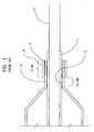
- In many prior methods of manufacturing catheter assemblies, an example of which is illustrated in PRIOR ART
FIG. 1 , joint formation is accomplished by overlapping (e.g. a lap weld configuration) thecomponents 1 and 2 to be joined on a mandrel 3 and heating a region of the overlapping components to form a weld or joint 4. Because the components are typically cylindrical in shape (or at least in the regions where they are to be joined) and inherently have differing diameters to accommodate their overlap, the components tend to form aspace 5 therebetween. Such a space presents difficulties in maintaining proper and continuous engagement between the components during joint formation. To address this, aheat shrink 6 or other constricting device is thus used to force thecomponents 1 and 2 together during heating. Where thecomponents 1 and 2 are a catheter shaft and a balloon waist, typically the joint 4 is about 1 mm in length. To prevent inadvertent heating and possible damage to theballoon cone 6, approximately 0.5 mm of thewaist 2 immediately adjacent to thecone 6 remains un-welded. This un-joined region of the catheter/balloon interface may contribute to joint failure during expansion of the balloon under pressure and present difficulties during the folding process. - In addition to the above, it is also noted that such prior manufacturing methods, also tend to provide a rather abrupt transition between the balloon and catheter shaft which may affect catheter flexibility, trackability, and/or cross-over performance of the resulting catheter assembly.
- Thus, a need exists to provide a catheter with joints that not only are adequately sealed and resistant to bond failure, but which do not deter the overall performance of the catheter. A method of manufacturing such a catheter is also needed.
- Without limiting the scope of the invention a brief summary of some of the claimed embodiments of the invention is set forth below. Additional details of the summarized embodiments of the invention and/or additional embodiments of the invention may be found in the Detailed Description of the Invention below.
- At least one embodiment of the invention is directed to forming a joint between two or more overlapping components having a substantially conic or frusto- conical shape.
- In at least one embodiment, the invention is directed to a catheter that utilizes a tapered or frusto-conical joint between one or more components. Some embodiments of the invention are directed to the manufacturing of catheters employing such tapered joints. The taper defined along the interface of the joined components allows the components to be in intimate or immediate contact prior to and during any subsequent bonding process such as heat or laser welding.
- In at least one embodiment a region of a catheter shaft is provided with a tapered region. The tapered region defines an angle relative to the un-tapered region of the catheter shaft. The taper may vary in angle, direction and degree (extent) as desired. In at least one embodiment the angle is about 1 to about 7 degrees. In some embodiments the angle is about 10 degrees or less. In some embodiments the angle is about 25 degrees or less.
- Where the catheter is a balloon catheter, the balloon is provided with a waist having a corresponding angle to that of the tapered region of the catheter shaft such that the waist and the tapered region are substantially parallel to one another when engaged.
- In at least one embodiment the balloon waist is sealingly engaged to the tapered region by heat or laser welding to form a weld site. In some embodiments the balloon waist and the tapered region are joined together without the use of a heat shrink. In at least one embodiment the weld site is defined by the interface of the entire length of the balloon waist and the tapered region of the catheter shaft.
- In some embodiments a cooling fluid is applied to the weld site during the welding process. In at least one embodiment the cooling fluid is liquid or gaseous N2. In at least on embodiment the cooling fluid is a stream of cooled air.
- In some embodiments the components of the catheter, which are to be joined together, may be optically clear relative to the wave-length of the laser light used to weld the components together. In such cases a site-specific layer of light absorbent material may be applied to and/or between the components to absorb the laser light and bring one or both components to their respective melting points along the weld site.
- These and other embodiments which characterize the invention are pointed out with particularity in the claims annexed hereto and forming a part hereof. However, for a better understanding of the invention, its advantages and objectives obtained by its use, reference should be made to the drawings which form a further part hereof and the accompanying descriptive matter, in which there is illustrated and described a embodiments of the invention.
- A detailed description of the invention is hereafter described with specific reference being made to the drawings.
FIG. 1 illustrates a PRIOR ART catheter assembly process.FIG. 2 is a partial longitudinal cross-sectional view of an embodiment of the invention comprising a catheter assembly shown during assembly.FIG. 3 is a longitudinal cross-sectional view of an embodiment of the invention including a catheter assembly having tapered joints.FIG. 3a is an enlarged view of a portion of the catheter assembly shown inFIG. 3 wherein the joint between an inner catheter shaft and the distal balloon waist is illustrated.FIG. 3b is an enlarged view of a portion of the catheter assembly shown inFIG. 3 wherein the joint between an outer catheter shaft and the proximal balloon waist is illustrated.- While this invention may be embodied in many different forms, there are described in detail herein specific preferred embodiments of the invention. This description is an exemplification of the principles of the invention and is not intended to limit the invention to the particular embodiments illustrated.
- For the purposes of this disclosure, like reference numerals in the figures shall refer to like features unless otherwise indicated.
- In at least one embodiment, the present invention is directed to a balloon catheter, such as for
example catheter 10 illustrated inFIG. 3 , wherein the catheter is provided with one or moretapered engagement areas engagements areas cylindrical portions respective catheter shafts engagement areas catheter 10 with a less abrupt transition between theballoon 12 andcatheter shafts 14 and/or 16. Balloon 12 may be any type of balloon. The balloon may be suitable for angioplasty, stent deliver or other uses. Where the balloon is used to deploy a stent thecatheter 10 may also include a stent or similar implantable prosthesis, for implantation into a body vessel or lumen.- By providing the
inner shaft 14 of thecatheter 10 with a tapered or frusto-conical shapedengagement region 20 and likewise providing theballoon 12 with adistal waist 30 having a corresponding shape, theinner shaft 14 and theballoon waist 30 may be forced tightly together as a result of the self-locking tapered shape. In order for thecomponents reference numeral 100 in FIG. 3 a, formed by the substantiallycylindrical portion 21 of theshaft 14 and the taper or frusto-conical region 20 is preferably between about 1 and about 7 degrees. In some embodiments theangle 100 may be greater than 7 degrees. In at least one embodiment the angle is about 25 degrees or less. - Because of the self-locking aspect of the
engagement region 20 and thedistal balloon waist 30, there is no longer a need to utilize a heat shrink layer, such as is shown in PRIOR ARTFIG. 1 to push the components together during welding such as is shown inFIG. 2 . Instead, a laser orother heating mechanism 50 may be used to directly or indirectly (e.g. Through Transmission Laser Welding) heat theregion 20 and/ordistal waist 30 to form a joint, depicted as dotted-line 52 inFIG. 2 , therebetween. - While a heat shrink material may be used, by avoiding the use of a heat shrink only that portion of the assembly to which is desired to be joined need be heated. As a result, the joint 52 may extend through the entire length of the
balloon waist 30 thereby avoiding the presence of an unjoined region between the catheter shaft and balloon waist, such as is common in many prior catheter assemblies as illustrated in PRIOR ARTFIG. 1 , previously discussed. - As compared to a more traditional joint between
cylindrical components 1 and 2, such as is shown in PRIOR ARTFIG. 1 , the use of a tapered joint 52, such as is shown inFIG. 2 , provides thecatheter 10 with an increase in the transition angle, indicated atreference numeral 200, between thedistal cone 34 and thedistal waist 30. Such an increased transition angle provides a narrower catheter profile in the area of the joint and provides the balloon with a more gradual and potentially less traumatic entrance profile. - While the
catheter 10 is provided with a tapered joint 52 between thedistal waist 30 and theinner shaft 14, such as is shown inFIGs. 3 and 3 a, such a tapered joint 54 may also be provided between theouter shaft 16 and theproximal waist 32, such as is shown inFIGs. 3 and3b . In some embodiments joint 54 may be configured to aid in balloon deflation as well. - Where the
balloon 12 is engaged to theouter shaft 16, theouter shaft 16 is provided with a frusto-conical shapedengagement region 22. In the same manner as previously discussed in relation to thedistal engagement region 20, theproximal engagement region 22 provides the catheter with a self-locking engagement between theouter shaft 16 and theproximal balloon waist 32. Provided that theangle 100 of the taper or frusto-conical region 22 and the substantiallycylindrical portion 23 of thecatheter shaft 16 is about 25 degrees or less, and in some embodiments between about 1 and about 7 degrees. It should be noted that while in some embodiments theangle 100 is about 25 degrees or less, in alternative embodiments other angles may be used. Any angle that provides the advantageous features described herein may be suitable for use in the formation of the medical device in question. - The
balloon 12 andshaft 14 and/or 16 may be of any material desired. For example it is possible to make balloons from a variety of materials that are generally of the thermoplastic polymeric type. Any suitable balloon materials include, but are not limited to: polyamides; polyethylenes, ionomers, ethylene-butylene-styrene block copolymers blended with low molecular weight polystyrene and, optionally, polypropylene, and similar compositions substituting butadiene or isoprene in place of the ethylene and butylene; poly(vinyl chloride); polyurethanes; copolyesters; thermoplastic rubbers; silicone-polycarbonate copolymers; polyamides; Pebax; Nylon; and ethylene- vinyl acetate copolymers. Orientable polyesters, especially polyethylene terephthalate (PET), are among the preferred materials for forming catheter balloons. - Other references illustrating the materials and methods of making catheter balloons include for example:
US 4,47,989 andUS 4,456,000 to Schjeldahl et al ;US 4,490,421 ,US Re 32,983 andRe 33,561 to Levy ;US 4,906,244 ,US 5,108,415 ,US 5,156,612 to Pinchuck et al ; andUS 5,807,520 to Wang et al . - Catheter shafts and other components can be made from any suitable material(s).
- Methods of assembling the
catheter 10 have been referenced above. Assembly of the distal end region of the catheter is depicted inFIG. 2 and such a depiction may be extrapolated to assemble the proximal end region as well. As shown inFIG. 2 theinner shaft 14 is disposed about amandrel 102 having a region shaped to correspond to that of the taperedengagement region 20. In some embodiments however, themandrel 102 has a substantially uniform diameter, and the desired tapered shape of theregion 20 is a result of a variation in the shape and/or thickness of theinner shaft 14 adjacent to theballoon waist 30. - Once positioned, the
balloon 12 is disposed about theshaft 14 and thedistal waist 30 is slide over theengagement region 20 to provide the self-locking engagement described above. Once theengagement region 20 and thedistal waist 30 are properly overlapped and aligned a laser orother heating device 50 will heat the one or more of the layers to at least its melting point to form the joint 52 between the layers. - Formation of the joint 54 between the
outer shaft 16 and theproximal balloon waist 32 may be similarly accomplished however use of a support mandrel may be unnecessary as theinner shaft 14 may act as a supporting member during formation of the joint 54. Alternatively a hollow mandrel and/or sacrificial mandrel may be inserted into the catheter around theinner shaft 14 in order to provide support to theengagement region 22 of theouter shaft 16. Additional methods of supporting the formation of joint 54 are recognized and are incorporated herein. - As indicated above in at least one embodiment it may be necessary to utilize Through Transmission Laser Welding (TTLW) to properly form the joint 52. For example, in embodiments where the
shaft 14 and theballoon 12 are constructed of materials which are substantially transparent to the wavelength of the particular form of laser energy which thelaser 52 emits, a layer of transition material, selected to absorb the wavelength of the laser, is positioned between the shaft and balloon in order to allow the transition material to be heated by the laser energy and thus conductively heat the surrounding layers to the desired melt point. - In addition to the above, it must be noted that the tapered
engagement joints areas 20 and/or 22 and thecorresponding balloon waists catheter 10 depicted inFIG. 3 is shown equipped with both taperedjoints - As indicated above, it is understood that the method of joint formation and the tapered joints described herein are not limited to use with catheters and their assembly, but may be suitable for use in forming connections between any two overlapping components.
- The
catheter 10 shown and described herein may be utilized for any of a variety of purposes including but not limited to perfusion, angioplasty procedures, stent delivery, device implantation/retrieval, drug delivery, etc. In at least one embodiment thecatheter 10 is equipped with one or more implantable medical devices such as a stent, graft, stent-graft, vena cava filter, expandable framework, etc. - The above disclosure is intended to be illustrative and not exhaustive. This description will suggest many variations and alternatives to one of ordinary skill in this art. The various elements shown in the individual figures and described above may be combined or modified for combination as desired. All these alternatives and variations are intended to be included within the scope of the claims where the term "comprising" means "including, but not limited to". Those familiar with the art may recognize other equivalents to the specific embodiments described herein which equivalents are also intended to be encompassed by the claims.
- Further, the particular features presented in the dependent claims can be combined with each other in other manners within the scope of the invention such that the invention should be recognized as also specifically directed to other embodiments having any other possible combination of the features of the dependent claims. For instance, for purposes of claim publication, any dependent claim which follows should be taken as alternatively written in a multiple dependent form from all prior claims which possess all antecedents referenced in such dependent claim if such multiple dependent format is an accepted format within the jurisdiction (e.g. each claim depending directly from claim 1 should be alternatively taken as depending from all previous claims). In jurisdictions where multiple dependent claim formats are restricted, the following dependent claims should each be also taken as alternatively written in each singly dependent claim format which creates a dependency from a prior antecedent-possessing claim other than the specific claim listed in such dependent claim below.
- This completes the description of the preferred and alternate embodiments of the invention. Those skilled in the art may recognize other equivalents to the specific embodiment described herein which equivalents are intended to be encompassed by the claims attached hereto.
- This PCT application claims priority from
US Application No. 11/020,540, filed on December 22, 2004 US2006135909 )
Claims (10)
- A catheter assembly (10) comprising:• at least one catheter shaft (14) comprising a substantially cylindrical portion and• a balloon, the balloon having a proximal waist (32) and a distal waist, wherein the proximal waist has a length and the distal waist has a length,characterised in that• the at least one catheter shaft during assembly, prior to any bonding process of the at least one catheter shaft and the balloon, comprises at least one tapered portion (20), the at least one tapered portion forming an angle with the cylindrical portion of about 1 degree to about 25 degree and being in intimate contact with the entire length of the at least one of the proximal waist and distal waist.
- The catheter assembly of claim 1 wherein the at least one catheter shaft comprises an inner catheter shaft and an outer catheter shaft, the outer catheter shaft disposed about a portion of the inner catheter shaft, the inner catheter shaft comprising an inner shaft substantially cylindrical portion and an inner shaft tapered portion, the distal waist being in intimate contact with the inner shaft tapered portion.
- The catheter assembly of claim 2 wherein the outer catheter shaft comprises an outer shaft substantially cylindrical portion and an outer shaft tapered portion, the proximal waist being in intimate contact with the outer shaft tapered portion.
- The catheter assembly of claim 1 wherein the at least one catheter shaft comprises an inner catheter shaft and an outer catheter shaft, the outer catheter shaft disposed about a portion of the inner catheter shaft, the outer catheter shaft further comprising an outer shaft substantially cylindrical portion and an outer shaft tapered portion, the proximal waist being in intimate contact with the outer shaft tapered portion.
- The catheter assembly of claim 1 wherein the angle is about 1 degree to about 7 degrees.
- The catheter assembly of claim 1, wherein the at least one of the proximal waist and distal waist is in self-locking engagement with the at least one tapered portion.
- A method of forming a joint between tubular components comprising the following steps to be performed in the following order:• providing a balloon, the balloon having a balloon waist, and a cathether shaft, the balloon waist having a first substantially cylindrical portion and a first tapered portion adjacent thereto, a first angle being formed between the first substantially cylindrical portion and the first tapered portion is about 1 degree to about 25 degrees, the catheter shaft having a second substantially cylindrical portion and a second tapered portion adjacent thereto, a second angle being formed between the second cylindrical portion and the second tapered portion being substantially the same as the first angle;• overlapping the first tapered portion about the second tapered portion thereby forming an interface therebetween;• applying heat only to the first tapered portion and the second tapered portion such that a weld is formed along the interface.
- The method of claim 7 wherein the balloon waist is welded to the catheter shaft without the use of a heat shrink.
- The method of claim 8 wherein interface of the first component and the second component has a length, the weld being formed along the entire length.
- The method of claim 7, wherein prior to the step of applying heat, the first tapered portion and the second tapered portion are in self-locking engagement.
Applications Claiming Priority (2)
| Application Number | Priority Date | Filing Date | Title |
|---|---|---|---|
| US11/020,540US8298179B2 (en) | 2004-12-22 | 2004-12-22 | Catheter assembly with tapered joints and method of manufacture |
| PCT/US2005/041987WO2006068749A1 (en) | 2004-12-22 | 2005-11-18 | Catheter assembly with tapered joints and method of manufacture |
Publications (2)
| Publication Number | Publication Date |
|---|---|
| EP1827548A1 EP1827548A1 (en) | 2007-09-05 |
| EP1827548B1true EP1827548B1 (en) | 2012-01-18 |
Family
ID=36090754
Family Applications (1)
| Application Number | Title | Priority Date | Filing Date |
|---|---|---|---|
| EP05851877ANot-in-forceEP1827548B1 (en) | 2004-12-22 | 2005-11-18 | Catheter assembly with tapered joints and method of manufacture |
Country Status (6)
| Country | Link |
|---|---|
| US (1) | US8298179B2 (en) |
| EP (1) | EP1827548B1 (en) |
| JP (1) | JP2008525105A (en) |
| AT (1) | ATE541605T1 (en) |
| CA (1) | CA2589856A1 (en) |
| WO (1) | WO2006068749A1 (en) |
Families Citing this family (22)
| Publication number | Priority date | Publication date | Assignee | Title |
|---|---|---|---|---|
| US8298179B2 (en)* | 2004-12-22 | 2012-10-30 | Boston Scientific Scimed, Inc. | Catheter assembly with tapered joints and method of manufacture |
| CA2676787A1 (en)* | 2007-02-05 | 2008-08-14 | Boston Scientific Limited | System with catheter system and an adaptor comprising a friction reducing sleeve, and methods of use |
| EP2207585A1 (en)* | 2007-11-06 | 2010-07-21 | Coloplast A/S | Balloon catheter |
| US20090234282A1 (en)* | 2008-03-17 | 2009-09-17 | Medtronic Vascular, Inc. | Outer Catheter Shaft to Balloon Joint |
| US8163123B2 (en)* | 2008-07-31 | 2012-04-24 | Boston Scientific Scimed, Inc. | Bifurcation catheter dual balloon bond and methods |
| JP2011206171A (en)* | 2010-03-29 | 2011-10-20 | Terumo Corp | Balloon catheter and method for manufacturing the same |
| CN107096111A (en) | 2011-05-26 | 2017-08-29 | 雅培心血管系统有限公司 | The conduit of thin hypotube is cut with stairstepping |
| WO2013003757A2 (en) | 2011-06-30 | 2013-01-03 | The Spectranetics Corporation | Reentry catheter and method thereof |
| US8956376B2 (en) | 2011-06-30 | 2015-02-17 | The Spectranetics Corporation | Reentry catheter and method thereof |
| US8998936B2 (en) | 2011-06-30 | 2015-04-07 | The Spectranetics Corporation | Reentry catheter and method thereof |
| CN102793962A (en)* | 2012-07-20 | 2012-11-28 | 易生科技(北京)有限公司 | Balloon dilatation catheter |
| US9078991B2 (en)* | 2013-03-04 | 2015-07-14 | Vascular Solutions, Inc. | Vascular dilator systems, kits, and methods |
| US20160023402A1 (en)* | 2014-07-28 | 2016-01-28 | Cook Medical Technologies Llc | Plastic welding system and method of making medical device |
| CN206355424U (en) | 2014-09-04 | 2017-07-28 | 雅培心血管系统有限公司 | Balloon catheter |
| CN205287203U (en) | 2014-09-04 | 2016-06-08 | 雅培心血管系统有限公司 | balloon catheter |
| CN106166323A (en) | 2015-05-19 | 2016-11-30 | 雅培心血管系统有限公司 | Balloon catheter |
| EP3095480B1 (en) | 2015-05-19 | 2021-01-13 | Abbott Cardiovascular Systems, Inc. | Catheter having monolithic multilayer distal outer member |
| CN107049381B (en)* | 2017-06-03 | 2019-04-30 | 成都五义医疗科技有限公司 | A casing assembly containing a mobile inflatable airbag |
| CN109864808B (en)* | 2017-06-03 | 2021-07-27 | 成都五义医疗设备有限公司 | Improved sleeve assembly containing air bag |
| CN109820578B (en)* | 2017-06-03 | 2021-03-23 | 成都五义医疗科技有限公司 | Sleeve assembly containing air bag |
| CN109646094B (en)* | 2017-06-03 | 2021-05-25 | 成都五义医疗科技有限公司 | Thimble assembly containing hook-shaped air bag |
| CN110051921A (en)* | 2018-01-18 | 2019-07-26 | 深圳市信立泰生物医疗工程有限公司 | A kind of taper drug coated balloon catheter |
Family Cites Families (26)
| Publication number | Priority date | Publication date | Assignee | Title |
|---|---|---|---|---|
| US4251305A (en)* | 1978-11-01 | 1981-02-17 | Baxter Travenol Laboratories, Inc. | Method of radiant heat sealing of a balloon onto a catheter employing tinted shrink tubing |
| US4395806A (en)* | 1980-05-08 | 1983-08-02 | Sorenson Research Co., Inc. | Method of manufacturing a detachable balloon catheter assembly |
| US4943278A (en)* | 1988-02-29 | 1990-07-24 | Scimed Life Systems, Inc. | Dilatation balloon catheter |
| US4913701A (en)* | 1988-10-06 | 1990-04-03 | Numed, Inc. | Balloon catheter and method of manufacturing the same |
| US5156595A (en)* | 1989-12-28 | 1992-10-20 | Scimed Life Systems, Inc. | Dilatation balloon catheter and method of manufacturing |
| WO1991013649A1 (en)* | 1990-03-16 | 1991-09-19 | Medtronic, Inc. | Dilatation catheter |
| US5267959A (en)* | 1991-11-29 | 1993-12-07 | Schneider, Inc. | Laser bonding of angioplasty balloon catheters |
| US5503631A (en)* | 1992-10-09 | 1996-04-02 | Terumo Kabushiki Kaisha | Lubricious catheter balloon for vasodilation |
| US5409495A (en)* | 1993-08-24 | 1995-04-25 | Advanced Cardiovascular Systems, Inc. | Apparatus for uniformly implanting a stent |
| US5899882A (en)* | 1994-10-27 | 1999-05-04 | Novoste Corporation | Catheter apparatus for radiation treatment of a desired area in the vascular system of a patient |
| US5549552A (en)* | 1995-03-02 | 1996-08-27 | Scimed Life Systems, Inc. | Balloon dilation catheter with improved pushability, trackability and crossability |
| US6129707A (en)* | 1998-01-21 | 2000-10-10 | Advanced Cardiovascular Systems, Inc. | Intravascular catheter with expanded distal tip |
| JP3996267B2 (en) | 1998-05-12 | 2007-10-24 | エルピーダメモリ株式会社 | Semiconductor memory device |
| CA2369307C (en)* | 1999-05-11 | 2009-04-07 | Kaneka Corporation | Balloon catheter |
| US6702802B1 (en)* | 1999-11-10 | 2004-03-09 | Endovascular Technologies, Inc. | Catheters with improved transition |
| US6746424B2 (en)* | 1999-12-11 | 2004-06-08 | Advanced Cardiovascular Systems, Inc. | Shaftless balloon |
| US6723113B1 (en)* | 2000-01-19 | 2004-04-20 | Cordis Neurovascular, Inc. | Inflatable balloon catheter seal and method |
| US6575934B2 (en)* | 2000-12-21 | 2003-06-10 | Advanced Cardiovascular Systems, Inc. | Low profile catheter |
| US20020082553A1 (en)* | 2000-12-22 | 2002-06-27 | Advanced Cardiovascular Systems, Inc. | Balloon designs for angioplasty |
| US6902571B2 (en)* | 2002-08-29 | 2005-06-07 | Advanced Cardiovascular Systems, Inc. | Compacted catheter balloon and method of incremental compaction |
| US6953470B2 (en)* | 2002-09-11 | 2005-10-11 | Boston Scientific Scimed, Inc. | Catheter support |
| US7323233B2 (en)* | 2002-09-26 | 2008-01-29 | Scimed Life Systems, Inc. | Sheath materials and processes |
| US7141059B2 (en)* | 2002-12-12 | 2006-11-28 | Advanced Cardiovascular Systems, Inc. | Balloon catheter having a flexible distal end |
| US6955658B2 (en)* | 2003-01-23 | 2005-10-18 | Medtronic Vascular, Inc. | Mold for forming a medical balloon |
| US7575568B2 (en)* | 2003-12-10 | 2009-08-18 | Boston Scientific Scimed, Inc. | Catheter distal tip |
| US8298179B2 (en)* | 2004-12-22 | 2012-10-30 | Boston Scientific Scimed, Inc. | Catheter assembly with tapered joints and method of manufacture |
- 2004
- 2004-12-22USUS11/020,540patent/US8298179B2/ennot_activeExpired - Fee Related
- 2005
- 2005-11-18WOPCT/US2005/041987patent/WO2006068749A1/enactiveApplication Filing
- 2005-11-18JPJP2007548230Apatent/JP2008525105A/ennot_activeWithdrawn
- 2005-11-18ATAT05851877Tpatent/ATE541605T1/enactive
- 2005-11-18EPEP05851877Apatent/EP1827548B1/ennot_activeNot-in-force
- 2005-11-18CACA002589856Apatent/CA2589856A1/ennot_activeAbandoned
Also Published As
| Publication number | Publication date |
|---|---|
| US20060135909A1 (en) | 2006-06-22 |
| ATE541605T1 (en) | 2012-02-15 |
| CA2589856A1 (en) | 2006-06-29 |
| EP1827548A1 (en) | 2007-09-05 |
| US8298179B2 (en) | 2012-10-30 |
| JP2008525105A (en) | 2008-07-17 |
| WO2006068749A1 (en) | 2006-06-29 |
Similar Documents
| Publication | Publication Date | Title |
|---|---|---|
| EP1827548B1 (en) | Catheter assembly with tapered joints and method of manufacture | |
| EP1234595B1 (en) | Through-transmission welding of catheter components | |
| US20030135231A1 (en) | Catheter bond configuration | |
| US7833193B2 (en) | Catheter shaft junction having a polymeric multilayered sleeve with a low processing temperature outer layer | |
| EP2148715B1 (en) | Catheter having a readily bondable multilayer soft tip | |
| JP6758031B2 (en) | Balloon catheter | |
| US9381327B2 (en) | Balloon catheter | |
| JP2016055165A (en) | Balloon catheter | |
| CN103796707A (en) | Catheter with stepped skived hypotube | |
| EP0618861A1 (en) | Laser bonding of angioplasty balloon catheters | |
| JP2006509586A (en) | Balloon catheter with flexible distal end | |
| US6699273B2 (en) | Sleeve welding collar | |
| US20030139760A1 (en) | Shaftless balloon | |
| US20040004311A1 (en) | Tacking method and apparatus | |
| WO2016152666A1 (en) | Catheter and catheter manufacturing method | |
| US7488304B2 (en) | Covered hypotube to distal port bond | |
| JP4192180B2 (en) | Catheter manufacturing method | |
| JPH1119216A (en) | Catheter and manufacture of catheter | |
| JP2016214821A (en) | Catheter having monolithic multilayer distal outer member | |
| JP2013111089A (en) | Balloon catheter |
Legal Events
| Date | Code | Title | Description |
|---|---|---|---|
| PUAI | Public reference made under article 153(3) epc to a published international application that has entered the european phase | Free format text:ORIGINAL CODE: 0009012 | |
| 17P | Request for examination filed | Effective date:20070628 | |
| AK | Designated contracting states | Kind code of ref document:A1 Designated state(s):AT BE BG CH CY CZ DE DK EE ES FI FR GB GR HU IE IS IT LI LT LU LV MC NL PL PT RO SE SI SK TR | |
| RIN1 | Information on inventor provided before grant (corrected) | Inventor name:HOLMAN, THOMAS J. Inventor name:ALI, AFSAR | |
| DAX | Request for extension of the european patent (deleted) | ||
| 17Q | First examination report despatched | Effective date:20091218 | |
| GRAP | Despatch of communication of intention to grant a patent | Free format text:ORIGINAL CODE: EPIDOSNIGR1 | |
| GRAS | Grant fee paid | Free format text:ORIGINAL CODE: EPIDOSNIGR3 | |
| GRAA | (expected) grant | Free format text:ORIGINAL CODE: 0009210 | |
| RAP1 | Party data changed (applicant data changed or rights of an application transferred) | Owner name:BOSTON SCIENTIFIC LIMITED | |
| AK | Designated contracting states | Kind code of ref document:B1 Designated state(s):AT BE BG CH CY CZ DE DK EE ES FI FR GB GR HU IE IS IT LI LT LU LV MC NL PL PT RO SE SI SK TR | |
| REG | Reference to a national code | Ref country code:GB Ref legal event code:FG4D | |
| REG | Reference to a national code | Ref country code:CH Ref legal event code:EP | |
| REG | Reference to a national code | Ref country code:NL Ref legal event code:T3 Ref country code:IE Ref legal event code:FG4D Ref country code:AT Ref legal event code:REF Ref document number:541605 Country of ref document:AT Kind code of ref document:T Effective date:20120215 | |
| REG | Reference to a national code | Ref country code:DE Ref legal event code:R096 Ref document number:602005032333 Country of ref document:DE Effective date:20120315 | |
| LTIE | Lt: invalidation of european patent or patent extension | Effective date:20120118 | |
| PG25 | Lapsed in a contracting state [announced via postgrant information from national office to epo] | Ref country code:LT Free format text:LAPSE BECAUSE OF FAILURE TO SUBMIT A TRANSLATION OF THE DESCRIPTION OR TO PAY THE FEE WITHIN THE PRESCRIBED TIME-LIMIT Effective date:20120118 Ref country code:IS Free format text:LAPSE BECAUSE OF FAILURE TO SUBMIT A TRANSLATION OF THE DESCRIPTION OR TO PAY THE FEE WITHIN THE PRESCRIBED TIME-LIMIT Effective date:20120518 Ref country code:BG Free format text:LAPSE BECAUSE OF FAILURE TO SUBMIT A TRANSLATION OF THE DESCRIPTION OR TO PAY THE FEE WITHIN THE PRESCRIBED TIME-LIMIT Effective date:20120418 Ref country code:BE Free format text:LAPSE BECAUSE OF FAILURE TO SUBMIT A TRANSLATION OF THE DESCRIPTION OR TO PAY THE FEE WITHIN THE PRESCRIBED TIME-LIMIT Effective date:20120118 | |
| PG25 | Lapsed in a contracting state [announced via postgrant information from national office to epo] | Ref country code:PL Free format text:LAPSE BECAUSE OF FAILURE TO SUBMIT A TRANSLATION OF THE DESCRIPTION OR TO PAY THE FEE WITHIN THE PRESCRIBED TIME-LIMIT Effective date:20120118 Ref country code:LV Free format text:LAPSE BECAUSE OF FAILURE TO SUBMIT A TRANSLATION OF THE DESCRIPTION OR TO PAY THE FEE WITHIN THE PRESCRIBED TIME-LIMIT Effective date:20120118 Ref country code:FI Free format text:LAPSE BECAUSE OF FAILURE TO SUBMIT A TRANSLATION OF THE DESCRIPTION OR TO PAY THE FEE WITHIN THE PRESCRIBED TIME-LIMIT Effective date:20120118 Ref country code:PT Free format text:LAPSE BECAUSE OF FAILURE TO SUBMIT A TRANSLATION OF THE DESCRIPTION OR TO PAY THE FEE WITHIN THE PRESCRIBED TIME-LIMIT Effective date:20120518 Ref country code:GR Free format text:LAPSE BECAUSE OF FAILURE TO SUBMIT A TRANSLATION OF THE DESCRIPTION OR TO PAY THE FEE WITHIN THE PRESCRIBED TIME-LIMIT Effective date:20120419 | |
| REG | Reference to a national code | Ref country code:AT Ref legal event code:MK05 Ref document number:541605 Country of ref document:AT Kind code of ref document:T Effective date:20120118 | |
| PG25 | Lapsed in a contracting state [announced via postgrant information from national office to epo] | Ref country code:CY Free format text:LAPSE BECAUSE OF FAILURE TO SUBMIT A TRANSLATION OF THE DESCRIPTION OR TO PAY THE FEE WITHIN THE PRESCRIBED TIME-LIMIT Effective date:20120118 | |
| PG25 | Lapsed in a contracting state [announced via postgrant information from national office to epo] | Ref country code:RO Free format text:LAPSE BECAUSE OF FAILURE TO SUBMIT A TRANSLATION OF THE DESCRIPTION OR TO PAY THE FEE WITHIN THE PRESCRIBED TIME-LIMIT Effective date:20120118 Ref country code:SE Free format text:LAPSE BECAUSE OF FAILURE TO SUBMIT A TRANSLATION OF THE DESCRIPTION OR TO PAY THE FEE WITHIN THE PRESCRIBED TIME-LIMIT Effective date:20120118 Ref country code:DK Free format text:LAPSE BECAUSE OF FAILURE TO SUBMIT A TRANSLATION OF THE DESCRIPTION OR TO PAY THE FEE WITHIN THE PRESCRIBED TIME-LIMIT Effective date:20120118 Ref country code:CZ Free format text:LAPSE BECAUSE OF FAILURE TO SUBMIT A TRANSLATION OF THE DESCRIPTION OR TO PAY THE FEE WITHIN THE PRESCRIBED TIME-LIMIT Effective date:20120118 Ref country code:EE Free format text:LAPSE BECAUSE OF FAILURE TO SUBMIT A TRANSLATION OF THE DESCRIPTION OR TO PAY THE FEE WITHIN THE PRESCRIBED TIME-LIMIT Effective date:20120118 Ref country code:SI Free format text:LAPSE BECAUSE OF FAILURE TO SUBMIT A TRANSLATION OF THE DESCRIPTION OR TO PAY THE FEE WITHIN THE PRESCRIBED TIME-LIMIT Effective date:20120118 | |
| PLBE | No opposition filed within time limit | Free format text:ORIGINAL CODE: 0009261 | |
| STAA | Information on the status of an ep patent application or granted ep patent | Free format text:STATUS: NO OPPOSITION FILED WITHIN TIME LIMIT | |
| PG25 | Lapsed in a contracting state [announced via postgrant information from national office to epo] | Ref country code:IT Free format text:LAPSE BECAUSE OF FAILURE TO SUBMIT A TRANSLATION OF THE DESCRIPTION OR TO PAY THE FEE WITHIN THE PRESCRIBED TIME-LIMIT Effective date:20120118 Ref country code:SK Free format text:LAPSE BECAUSE OF FAILURE TO SUBMIT A TRANSLATION OF THE DESCRIPTION OR TO PAY THE FEE WITHIN THE PRESCRIBED TIME-LIMIT Effective date:20120118 | |
| 26N | No opposition filed | Effective date:20121019 | |
| PG25 | Lapsed in a contracting state [announced via postgrant information from national office to epo] | Ref country code:AT Free format text:LAPSE BECAUSE OF FAILURE TO SUBMIT A TRANSLATION OF THE DESCRIPTION OR TO PAY THE FEE WITHIN THE PRESCRIBED TIME-LIMIT Effective date:20120118 | |
| REG | Reference to a national code | Ref country code:DE Ref legal event code:R097 Ref document number:602005032333 Country of ref document:DE Effective date:20121019 | |
| PG25 | Lapsed in a contracting state [announced via postgrant information from national office to epo] | Ref country code:ES Free format text:LAPSE BECAUSE OF FAILURE TO SUBMIT A TRANSLATION OF THE DESCRIPTION OR TO PAY THE FEE WITHIN THE PRESCRIBED TIME-LIMIT Effective date:20120429 | |
| REG | Reference to a national code | Ref country code:CH Ref legal event code:PL | |
| GBPC | Gb: european patent ceased through non-payment of renewal fee | Effective date:20121118 | |
| PG25 | Lapsed in a contracting state [announced via postgrant information from national office to epo] | Ref country code:CH Free format text:LAPSE BECAUSE OF NON-PAYMENT OF DUE FEES Effective date:20121130 Ref country code:LI Free format text:LAPSE BECAUSE OF NON-PAYMENT OF DUE FEES Effective date:20121130 | |
| PG25 | Lapsed in a contracting state [announced via postgrant information from national office to epo] | Ref country code:GB Free format text:LAPSE BECAUSE OF NON-PAYMENT OF DUE FEES Effective date:20121118 | |
| PG25 | Lapsed in a contracting state [announced via postgrant information from national office to epo] | Ref country code:MC Free format text:LAPSE BECAUSE OF NON-PAYMENT OF DUE FEES Effective date:20121130 Ref country code:TR Free format text:LAPSE BECAUSE OF FAILURE TO SUBMIT A TRANSLATION OF THE DESCRIPTION OR TO PAY THE FEE WITHIN THE PRESCRIBED TIME-LIMIT Effective date:20120118 | |
| PG25 | Lapsed in a contracting state [announced via postgrant information from national office to epo] | Ref country code:LU Free format text:LAPSE BECAUSE OF NON-PAYMENT OF DUE FEES Effective date:20121118 | |
| PG25 | Lapsed in a contracting state [announced via postgrant information from national office to epo] | Ref country code:HU Free format text:LAPSE BECAUSE OF FAILURE TO SUBMIT A TRANSLATION OF THE DESCRIPTION OR TO PAY THE FEE WITHIN THE PRESCRIBED TIME-LIMIT Effective date:20051118 | |
| REG | Reference to a national code | Ref country code:DE Ref legal event code:R082 Ref document number:602005032333 Country of ref document:DE Representative=s name:VOSSIUS & PARTNER PATENTANWAELTE RECHTSANWAELT, DE | |
| REG | Reference to a national code | Ref country code:DE Ref legal event code:R082 Ref document number:602005032333 Country of ref document:DE Representative=s name:VOSSIUS & PARTNER PATENTANWAELTE RECHTSANWAELT, DE | |
| REG | Reference to a national code | Ref country code:DE Ref legal event code:R081 Ref document number:602005032333 Country of ref document:DE Owner name:BOSTON SCIENTIFIC LIMITED, BM Free format text:FORMER OWNER: BOSTON SCIENTIFIC LIMITED, WEST INDIES, BB Effective date:20150202 Ref country code:DE Ref legal event code:R082 Ref document number:602005032333 Country of ref document:DE Representative=s name:VOSSIUS & PARTNER PATENTANWAELTE RECHTSANWAELT, DE Effective date:20141026 Ref country code:DE Ref legal event code:R082 Ref document number:602005032333 Country of ref document:DE Representative=s name:VOSSIUS & PARTNER PATENTANWAELTE RECHTSANWAELT, DE Effective date:20150202 Ref country code:DE Ref legal event code:R081 Ref document number:602005032333 Country of ref document:DE Owner name:BOSTON SCIENTIFIC LIMITED, BM Free format text:FORMER OWNER: BOSTON SCIENTIFIC LTD., HASTINGS, CHRIST CHURCH, BB Effective date:20120124 | |
| REG | Reference to a national code | Ref country code:FR Ref legal event code:PLFP Year of fee payment:12 | |
| REG | Reference to a national code | Ref country code:FR Ref legal event code:PLFP Year of fee payment:13 | |
| REG | Reference to a national code | Ref country code:FR Ref legal event code:PLFP Year of fee payment:14 | |
| PGFP | Annual fee paid to national office [announced via postgrant information from national office to epo] | Ref country code:DE Payment date:20191105 Year of fee payment:15 Ref country code:IE Payment date:20191111 Year of fee payment:15 Ref country code:NL Payment date:20191114 Year of fee payment:15 | |
| PGFP | Annual fee paid to national office [announced via postgrant information from national office to epo] | Ref country code:FR Payment date:20191014 Year of fee payment:15 | |
| REG | Reference to a national code | Ref country code:DE Ref legal event code:R119 Ref document number:602005032333 Country of ref document:DE | |
| REG | Reference to a national code | Ref country code:NL Ref legal event code:MM Effective date:20201201 | |
| PG25 | Lapsed in a contracting state [announced via postgrant information from national office to epo] | Ref country code:NL Free format text:LAPSE BECAUSE OF NON-PAYMENT OF DUE FEES Effective date:20201201 | |
| PG25 | Lapsed in a contracting state [announced via postgrant information from national office to epo] | Ref country code:FR Free format text:LAPSE BECAUSE OF NON-PAYMENT OF DUE FEES Effective date:20201130 Ref country code:IE Free format text:LAPSE BECAUSE OF NON-PAYMENT OF DUE FEES Effective date:20201118 | |
| PG25 | Lapsed in a contracting state [announced via postgrant information from national office to epo] | Ref country code:DE Free format text:LAPSE BECAUSE OF NON-PAYMENT OF DUE FEES Effective date:20210601 |